JP7007149B2 - connector - Google Patents
connector Download PDFInfo
- Publication number
- JP7007149B2 JP7007149B2 JP2017200417A JP2017200417A JP7007149B2 JP 7007149 B2 JP7007149 B2 JP 7007149B2 JP 2017200417 A JP2017200417 A JP 2017200417A JP 2017200417 A JP2017200417 A JP 2017200417A JP 7007149 B2 JP7007149 B2 JP 7007149B2
- Authority
- JP
- Japan
- Prior art keywords
- connector
- main body
- connector main
- pair
- hole
- Prior art date
- Legal status (The legal status is an assumption and is not a legal conclusion. Google has not performed a legal analysis and makes no representation as to the accuracy of the status listed.)
- Active
Links
Images


Landscapes
- Details Of Connecting Devices For Male And Female Coupling (AREA)
Description
本発明は、板状のパネルに設けられた貫通孔に挿入された状態にてパネルに取り付けられるコネクタ、に関する。 The present invention relates to a connector that is attached to a panel while being inserted into a through hole provided in the plate-shaped panel.
従来から、車両の車体(例えば、ピラー部分)を構成する板状のパネルに設けられた貫通孔に挿入されて係止されるコネクタが提案されている。例えば、従来のコネクタの一つは、コネクタ本体部を取り囲むように特定形状のフード部を備えており、この特定形状を利用してフード部の外表面を貫通孔に沿わせながらコネクタを移動させることにより、パネルへコネクタを取り付けるようになっている(例えば、特許文献1を参照。)。 Conventionally, a connector has been proposed which is inserted into a through hole provided in a plate-shaped panel constituting a vehicle body (for example, a pillar portion) and locked. For example, one of the conventional connectors is provided with a hood portion having a specific shape so as to surround the connector main body portion, and using this specific shape, the connector is moved while the outer surface of the hood portion is along the through hole. As a result, the connector is attached to the panel (see, for example, Patent Document 1).
上述した従来のコネクタには、コネクタ本体部を取り囲むフード部の特定形状を利用することで、パネルへのコネクタの取り付けを容易にしている。このフード部は、コネクタのパネルへの取り付けを補助する上では必要であるものの、コネクタとしての本来の機能(例えば、相手側コネクタとの電気的接続)の上では必ずしも必要ではない。このように本来的には必要ではない部材によってコネクタが大型化することは、出来る限り避けることが望ましい。 In the conventional connector described above, the connector can be easily attached to the panel by utilizing the specific shape of the hood portion that surrounds the connector main body portion. Although this hood portion is necessary to assist the attachment of the connector to the panel, it is not always necessary for the original function as a connector (for example, electrical connection with the mating connector). It is desirable to avoid increasing the size of the connector due to members that are not originally required.
本発明は、上述した事情に鑑みてなされたものであり、その目的は、パネルに設けられた貫通孔へのコネクタの容易な取り付けと、コネクタの小型化と、を両立可能なコネクタを提供することにある。 The present invention has been made in view of the above circumstances, and an object of the present invention is to provide a connector capable of easily attaching a connector to a through hole provided in a panel and reducing the size of the connector. There is something in it.
前述した目的を達成するために、本発明に係るコネクタは、下記(1)~(3)を特徴としている。
(1)
板状のパネルに設けられた貫通孔に挿入された状態にて前記パネルに取り付けられるコネクタであって、
コネクタ本体部と、前記コネクタ本体部の相手側コネクタとの嵌合方向の前端部に設けられ且つ前記コネクタ本体部を前記貫通孔の周縁部へ係止可能な係止部と、前記コネクタ本体部の前記係止部より前記嵌合方向の後方側の位置に前記係止部とは独立して設けられ且つ前記嵌合方向に直交する直交方向に沿って前記コネクタ本体部の外表面から互いに逆向きに突出する一対の凸部と、を備え、
前記コネクタ本体部は、
前記一対の凸部よりも前記嵌合方向における前方側にある該コネクタ本体部の前方部分の一部が前記貫通孔を通過した状態にて前記一対の凸部を前記貫通孔の周縁部に当接させると共に、前記一対の凸部と前記周縁部との当接箇所を通り且つ前記直交方向に延びる軸線周りに該コネクタ本体部を回転させることにより、該コネクタ本体部の前記前方部分の全体が前記貫通孔を通過する形状、を有する、
コネクタであること。
(2)
上記(1)に記載のコネクタであって、
前記コネクタ本体部の前記係止部より前記嵌合方向の後方側の位置に前記係止部とは独立して設けられ且つ前記コネクタ本体部を前記軸線周りに回転させるときの回転可能範囲を規制する規制部を、更に備える、
コネクタであること。
(3)
上記(2)に記載のコネクタにおいて、
前記一対の凸部は、
前記嵌合方向に交差する向きに延びる突条形状を有し、
前記規制部は、
前記一対の凸部の前記当接箇所以外の少なくとも一部分である、
コネクタであること。
In order to achieve the above-mentioned object, the connector according to the present invention is characterized by the following (1) to (3).
(1)
A connector that is attached to the panel while being inserted into a through hole provided in the plate-shaped panel.
A locking portion provided at the front end portion in the mating direction between the connector main body portion and the mating connector of the connector main body portion and capable of locking the connector main body portion to the peripheral edge portion of the through hole, and the connector main body portion. It is provided at a position on the rear side of the locking portion in the fitting direction independently of the locking portion, and is opposite to each other from the outer surface of the connector main body along the orthogonal direction orthogonal to the fitting direction. With a pair of convex parts protruding in the direction,
The connector body is
The pair of convex portions hit the peripheral edge of the through hole in a state where a part of the front portion of the connector main body portion on the front side in the fitting direction with respect to the pair of convex portions has passed through the through hole. By rotating the connector main body portion around an axis extending in the orthogonal direction and passing through the contact points between the pair of convex portions and the peripheral edge portion, the entire front portion of the connector main body portion is brought into contact with the connector main body portion. It has a shape that passes through the through hole.
Must be a connector.
(2)
The connector according to (1) above.
A rotatable range when the connector main body is rotated around the axis and is provided independently of the locking portion at a position rearward of the locking portion of the connector main body in the fitting direction. Further equipped with a regulatory department to regulate,
Must be a connector.
(3)
In the connector described in (2) above,
The pair of convex portions
It has a ridge shape extending in a direction intersecting the fitting direction, and has a ridge shape.
The regulatory department
At least a part of the pair of protrusions other than the contact point.
Must be a connector.
上記(1)の構成のコネクタによれば、コネクタをパネルに取り付ける際、コネクタ本体部の外表面から突出する一対の凸部を貫通孔の周縁部に当接させ、その一対の凸部と周縁部との当接箇所を中心にコネクタ本体部を回転させることにより、コネクタ本体部の前方部分の全体が貫通孔を通過できるように、コネクタ本体部の形状が設計されている。換言すると、コネクタ本体部の形状および一対の凸部が、上述した回転を利用した取り付け手法に適するように、設計されている。 According to the connector having the configuration of (1) above, when the connector is attached to the panel, a pair of convex portions protruding from the outer surface of the connector main body are brought into contact with the peripheral edge of the through hole, and the pair of convex portions and the peripheral edge thereof are brought into contact with each other. The shape of the connector main body is designed so that the entire front portion of the connector main body can pass through the through hole by rotating the connector main body around the contact point with the portion. In other words, the shape of the connector body and the pair of protrusions are designed to be suitable for the rotation-based mounting method described above.
よって、コネクタをパネルに取り付ける際、作業者は、一対の凸部を貫通孔の周縁部に押し付けるようにコネクタ本体部の前方部分の一部を貫通孔に挿入した後、コネクタ本体部を一対の凸部(実際には当接箇所)を中心に回転させることにより、コネクタ本体部を貫通孔に容易に挿入できる。更に、コネクタ本体部には一対の凸部が設けられるだけであるため、従来のコネクタのようにフード部を要する場合に比べ、コネクタを全体として小型化できる。 Therefore, when attaching the connector to the panel, the operator inserts a part of the front portion of the connector main body into the through hole so as to press the pair of convex portions against the peripheral edge of the through hole, and then inserts the connector main body into the pair. By rotating around the convex portion (actually, the contact point), the connector main body portion can be easily inserted into the through hole. Further, since the connector main body portion is provided with only a pair of convex portions, the connector can be miniaturized as a whole as compared with the case where a hood portion is required as in a conventional connector.
したがって、本構成のコネクタによれば、パネルに設けられた貫通孔へのコネクタの容易な取り付けと、コネクタの小型化と、を両立可能である。 Therefore, according to the connector having this configuration, it is possible to easily attach the connector to the through hole provided in the panel and to reduce the size of the connector at the same time.
上記(2)の構成のコネクタによれば、コネクタ本体部を当接箇所を中心に回転させるときの回転可能範囲を規制する規制部が、コネクタ本体部に設けられる。そのため、コネクタをパネルに取り付ける際、作業者が特に意識しなくても、コネクタが過剰に回転してコネクタの姿勢が取り付けに不適切な状態となること等を防止できる。よって、本構成のコネクタによれば、パネルに設けられた貫通孔へ更に容易にコネクタを取り付けられる。 According to the connector having the configuration of (2) above, the connector main body is provided with a restricting portion that regulates the rotatable range when the connector main body is rotated around the contact portion. Therefore, when the connector is attached to the panel, it is possible to prevent the connector from rotating excessively and the posture of the connector from becoming an inappropriate state for attachment even if the operator is not particularly conscious of it. Therefore, according to the connector of this configuration, the connector can be more easily attached to the through hole provided in the panel.
上記(3)の構成のコネクタによれば、一対の凸部が嵌合方向に交差する向きに延びる突条形状を有し、一対の凸部の当接箇所以外の少なくとも一部分が規制部として用いられる。そのため、一対の凸部と規制部とを別々の部材としてコネクタ本体部に設ける場合に比べ、コネクタの構造を単純化でき、コネクタを容易に製造できる。 According to the connector having the configuration of (3) above, the pair of convex portions have a ridge shape extending in a direction intersecting in the fitting direction, and at least a part other than the contact portion of the pair of convex portions is used as a restricting portion. Be done. Therefore, the structure of the connector can be simplified and the connector can be easily manufactured as compared with the case where the pair of convex portions and the restricting portion are provided as separate members in the connector main body portion.
本発明によれば、パネルに設けられた貫通孔へのコネクタの容易な取り付けと、コネクタの小型化と、を両立可能なコネクタを提供できる。 According to the present invention, it is possible to provide a connector capable of easily attaching a connector to a through hole provided in a panel and reducing the size of the connector.
以上、本発明について簡潔に説明した。更に、以下に説明される発明を実施するための形態(以下、「実施形態」という。)を添付の図面を参照して通読することにより、本発明の詳細は更に明確化されるであろう。 The present invention has been briefly described above. Further, the details of the present invention will be further clarified by reading through the embodiments described below (hereinafter referred to as "embodiments") with reference to the accompanying drawings. ..
<実施形態>
以下、図面を参照しながら、本発明の実施形態に係るコネクタ1について説明する。
<Embodiment>
Hereinafter, the
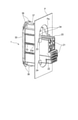
図1に示すように、コネクタ1は、板状のパネルPに設けられた貫通孔Paに挿入された状態にてパネルPに取り付けられ(図6も参照)、且つ、相手側コネクタ(図示省略)と嵌合した状態で使用される。パネルPとしては、典型的には、車両の車体(例えば、ピラー部)を構成する板状体が想定される。本例では、コネクタ1にオス端子が収容され、相手側コネクタにメス端子が収容される。
As shown in FIG. 1, the
以下、図1に示すように、「嵌合方向」、「幅方向」、「上下方向」、「前」、「後」、「上」及び「下」を定義する。「嵌合方向」、「幅方向」及び「上下方向」は、互いに直交する。 Hereinafter, as shown in FIG. 1, "fitting direction", "width direction", "vertical direction", "front", "rear", "upper" and "lower" are defined. The "fitting direction", "width direction" and "vertical direction" are orthogonal to each other.
図1に示すように、コネクタ1は、樹脂製のコネクタ本体部10を有する。コネクタ本体部10は、略直方体状の端子収容ブロック部20と、端子収容ブロック部20から一体で上方且つ前方に突出すると共に前方に開口する箱状のホロー部30と、を備える(図2及び図7等も参照)。
As shown in FIG. 1, the
端子収容ブロック部20には、複数の端子収容室21が嵌合方向に沿って貫通形成されている(図7を参照)。複数の端子収容室21には、後方に電線が接続された複数のオス端子(図示省略)が収容・固定されるようになっている。端子収容ブロック部20に収容・固定された複数のオス端子における前方に延びるそれぞれのタブ部は、ホロー部30の内部空間31内に位置している(露出している)。ホロー部30の内部空間31に相手側コネクタの端子収容ブロック部(図示省略)が収容(内挿)されることで、コネクタ1と相手側コネクタとが嵌合される。その結果、コネクタ1に収容された複数のオス端子と、相手側コネクタに収容された複数のメス端子との電気的導通がそれぞれ達成される。
A plurality of terminal
端子収容ブロック部20の上下方向且つ嵌合方向に沿って延びる両側壁22の嵌合方向途中位置における上端部及び下端部には、それぞれ、一対の凸部23及び一対の規制部24が、幅方向外側に突出するように一体で設けられている。本例では、凸部23及び規制部24はそれぞれ、直方体状の突出部となっている。以下、コネクタ本体部10において、凸部23及び規制部24が設けられた上記嵌合方向途中位置から前方側の部分を「前方部分11」と呼び、上記嵌合方向途中位置から後方側の部分を「後方部分12」と呼ぶこともある。
A pair of
ホロー部30は、その前端部がパネルPの貫通孔Paに係止される(図6も参照)。このため、前方からみて、ホロー部30の輪郭形状(後述する係止爪36及びロックビーク37を除く)は、概ね、貫通孔Paの形状(長穴形状)を若干縮小した相似形状を有している。
The front end of the
ホロー部30の上下方向且つ嵌合方向に沿って延びる両側壁32は、端子収容ブロック部20の両側壁22と比べて、幅方向外側に位置している。よって、両側壁32及び両側壁22のうち対応する側同士の境界部には、それぞれ、上下方向に延びる段差13が形成されている。
The
両側壁32には、幅方向外側に突出すると共に嵌合方向に亘って延びる複数のリブ33が、上下方向に間隔を空けて設けられている。各リブ33の後側端部には、後側に移動するにつれてリブ33の頂面が幅方向内側に移動するように傾斜するテーパ部33aが形成されている。このテーパ部33aは、パネルPにコネクタ本体部10を取り付ける際の貫通孔Paに対するコネクタ本体部10の幅方向のセンタリングを行い易くするために設けられている。
A plurality of
ホロー部30の端子収容ブロック部20から上方に突出する部分の後端面における幅方向両端部には、後方に突出する一対のガイドリブ34が設けられている。一対のガイドリブ34の頂面は、ホロー部30の前記後端面の上端における幅方向両端部と、端子収容ブロック部20の一対の凸部23の根元部の上部とを繋ぐように、後側に移動するにつれて下側に移動するよう傾斜している。一対のガイドリブ34は、後述するコネクタ本体部10の貫通孔Paへの案内、及び、パネルPにコネクタ本体部10を取り付ける際の貫通孔Paに対するコネクタ本体部10の上下方向のセンタリングを行い易くするために設けられている。
A pair of
ホロー部30の上壁及び下壁の後端部にもそれぞれ、後側に移動するにつれて上下方向内側に移動するように傾斜するテーパ部35が形成されている。この上下一対のテーパ部35も、上述した貫通孔Paに対するコネクタ本体部10の上下方向のセンタリングを行い易くするために設けられている。
The upper wall and the rear end of the lower wall of the
ホロー部30の前端部の上端部及び下端部にはそれぞれ、上下方向外側に突出する一対の係止爪36が設けられ、ホロー部30の上壁及び下壁にはそれぞれ、一対の係止爪36からパネルPの厚さ分だけ後側の位置にて、上下方向外側に突出するロックビーク37が設けられている。係止爪36及びロックビーク37は、コネクタ本体部10(より具体的には、ホロー部30)をパネルPに係止する機能を果たす。
A pair of locking
次いで、図2~図6を参照しながら、パネルPにコネクタ本体部10を取り付ける際の一連の手順について説明する。なお、図示はしていないが、実際には、端子収容ブロック部20には複数のオス端子が収容されており、複数のオス端子の後端側にそれぞれ接続された複数の電線が端子収容ブロック部20から後方へ延出している。
Next, a series of procedures for attaching the connector
まず、図2に示すように、コネクタ本体部10を上部が下部より前側に位置するように上下方向に傾斜させた状態で、一対の凸部23がパネルPの貫通孔Paの周縁部に当接するまで、コネクタ本体部10の前方部分11をパネルPの貫通孔Paに挿入していく(パネルPに対して前方部分11を前方へスライドさせていく)。図2に示す状態(一対の凸部23がパネルPの貫通孔Paの周縁部に当接した状態)では、前方部分11の略上半分がパネルPの貫通孔Paを通過している。
First, as shown in FIG. 2, a pair of
次いで、図3に示すように、一対の凸部23がパネルPの貫通孔Paの周縁部に当接した状態を維持しながら(即ち、一対の凸部23をパネルPに向けて前方に押し付けながら)、コネクタ本体部10を、一対の凸部23と貫通孔Paの周縁部との当接箇所Aを中心に幅方向に延びる軸線周りに、コネクタ本体部10の前端面の下端が貫通孔Paを通過するまで、回転させる。このように、コネクタ本体部10の前方部分11の全体が貫通孔Paを通過できるように、コネクタ本体部10の形状が設計されている。
Next, as shown in FIG. 3, while maintaining the state in which the pair of
次いで、図4に示すように、コネクタ本体部10を同じ向きに更に回転させながら、一対のガイドリブ34の傾斜した頂面を貫通孔Paの縁に当接させた状態を維持しつつその当接箇所Bを一対の凸部23の近傍位置から上方且つ前方へ斜めに滑らせていく。換言すると、コネクタ本体部10を同じ向きに更に回転させながら、一対のガイドリブ34の頂面を貫通孔Paの縁に対して滑らせつつ前方部分11を貫通孔Paに対して下方且つ後方へスライドさせていく。
Next, as shown in FIG. 4, while further rotating the connector
コネクタ本体部10の回転は、コネクタ本体部10の上下方向の傾斜がなくなるまで(即ち、コネクタ本体部10の嵌合方向がパネルPの平面に対する法線方向と一致するまで)継続され、前方部分11の下方且つ後方へのスライドは、当接箇所Bがガイドリブ34の頂面の上端付近に達するまで継続される。
The rotation of the connector
コネクタ本体部10の上下方向の傾斜がなくなり、且つ、当接箇所Bがガイドリブ34の頂面の上端付近に達した後は、上下一対のテーパ部35、及び、幅方向両側の複数のリブ33のテーパ部33aを、必要に応じて貫通孔Paの縁に当接させて滑らせるように、コネクタ本体部10を後方へ僅かにスライドさせて、貫通孔Paに対するコネクタ本体部10の上下方向及び幅方向のセンタリングを行う。
After the connector
その結果、図5に示すように、コネクタ本体部10が、コネクタ本体部10の上下方向の傾斜がなくなり、上下一対のテーパ部35及び全てのテーパ部33aが貫通孔Paを通過し、且つ、貫通孔Paに対するコネクタ本体部10の上下方向及び幅方向のセンタリングが完了した状態になる。
As a result, as shown in FIG. 5, the connector
そして、図5に示す状態から、コネクタ本体部10を後方へスライドさせていく。これにより、まず、貫通孔Paの上下縁が上下一対のロックビーク37に当接し乗り上がる。これに伴い、上下一対のロックビーク37が上下方向内側に弾性変形し、貫通孔Paの上下縁が弾性変形した上下一対のロックビーク37を乗り越える。
Then, from the state shown in FIG. 5, the connector
その結果、図6に示すように、上下一対のロックビーク37が弾性復帰すると共に、2対の(合計4本の)係止爪36がパネルPの貫通孔Paの周縁部(4か所)に当接する。即ち、パネルPの貫通孔Paの周縁部が、2対の係止爪36と上下一対のロックビーク37との間に挟まれるように、コネクタ本体部10(より具体的には、ホロー部30)がパネルPに係止される。これにより、パネルPに対するコネクタ本体部10の取り付けが完了する。
As a result, as shown in FIG. 6, the pair of upper and
以下、図7を参照しながら、コネクタ本体部10(より具体的には、端子収容ブロック部20)に設けられた一対の規制部24の機能について説明する。
Hereinafter, the functions of the pair of restricting
上述した図3に示す状態(一対の凸部23がパネルPの貫通孔Paの周縁部に当接し、且つ、コネクタ本体部10が上下方向に傾斜した状態)から、図4に示すような前方部分11の下方且つ後方へのスライド動作を行うことなく(一対の凸部23がパネルPの貫通孔Paの周縁部に当接した状態を維持しながら)、コネクタ本体部10の同じ向きへの回転を継続していくと、図7に示すように、一対の規制部24がパネルPの貫通孔Paの周縁部に当接し、これ以上、コネクタ本体部10が同じ向きに回転できなくなる。換言すると、一対の規制部24は、コネクタ本体部10の回転可能範囲を規制することで、コネクタ本体部10が過剰に回転してコネクタ本体部10の姿勢がパネルPへの取り付けに不適切な状態となること等を防止する機能を果たす。
From the state shown in FIG. 3 described above (a state in which the pair of
以上に説明したように、本実施形態に係るコネクタ1によれば、コネクタ1の嵌合方向に直交する軸線(幅方向に沿う軸線)に沿ってコネクタ本体部10の外表面から互いに逆向きに突出する一対の凸部23が、コネクタ本体部10に設けられている。そして、コネクタ1をパネルPに取り付ける際、この一対の凸部23を貫通孔Paの周縁部に当接させながら、一対の凸部23と貫通孔Paの周縁部との当接箇所A(図3を参照)を中心に軸線周りにコネクタ本体部10を回転させることにより、コネクタ本体部10の前方部分11の全体が貫通孔Paを通過するように、コネクタ本体部10の形状が設計されている。
As described above, according to the
よって、コネクタ1をパネルPに取り付ける際、作業者は、片手のみを利用して、一対の凸部23を貫通孔Paの周縁部に押し付けるようにコネクタ1を貫通孔Paに挿入させながら、コネクタ1を回転させることにより、容易にコネクタ1を貫通孔Paに挿入させることができる。更に、コネクタ本体部10に一対の凸部23が設けられるだけであるため、従来のコネクタに比べ、コネクタ1を全体として小型化できる。
Therefore, when attaching the
したがって、本構成のコネクタ1によれば、パネルPに設けられた貫通孔Paへのコネクタ1の容易な取り付けと、コネクタ1の小型化と、を両立可能である。
Therefore, according to the
更に、コネクタ本体部10を当接箇所Aを中心に軸線周りに回転させるときの回転可能範囲を規制する一対の規制部24が、コネクタ本体部10に設けられている。そのため、コネクタ1をパネルPに取り付ける際、作業者が意識しなくても、コネクタ1が過剰に回転してコネクタ1の姿勢が取り付けに不適切な状態となること等を防止できる。よって、本構成のコネクタ1によれば、パネルPに設けられた貫通孔Paへのコネクタ1の取り付けを、更に容易化できる。
Further, the connector
<他の態様>
なお、本発明は上記各実施形態に限定されることはなく、本発明の範囲内において種々の変形例を採用できる。例えば、本発明は、上述した実施形態に限定されるものではなく、適宜、変形、改良、等が可能である。その他、上述した実施形態における各構成要素の材質、形状、寸法、数、配置箇所、等は本発明を達成できるものであれば任意であり、限定されない。
<Other aspects>
The present invention is not limited to each of the above embodiments, and various modifications can be adopted within the scope of the present invention. For example, the present invention is not limited to the above-described embodiment, and can be appropriately modified, improved, and the like. In addition, the material, shape, dimensions, number, arrangement location, etc. of each component in the above-described embodiment are arbitrary as long as the present invention can be achieved, and are not limited.
例えば、上記実施形態では、コネクタ本体部10は、凸部23及び規制部24の双方を有している。しかし、コネクタ本体部10は、凸部23のみを有するように構成されてもよい。
For example, in the above embodiment, the connector
更に、上記実施形態では、凸部23は、直方体状の突出部となっている(図1及び図2等を参照)。これに対し、図8(a)に示すように、凸部23は、前面23aが上記実施形態と同様に平面(嵌合方向に直交する方向に拡がる平面)であり、上面23bが上方に突出する曲面形状(円筒側面の周方向の一部分に相当する曲面形状)であり、後面23cが下方に移動するにつれて後方に移動するように滑らかに傾斜している、突出部であってもよい。
Further, in the above embodiment, the
これにより、前面23aが平面であるので、図7に示すように最終的に一対の凸部23をパネルPに当接させる際に、前面23aをパネルPに密着させることができる。更に、上面23bが曲面形状であるので、取り付けの過程においてコネクタ本体部10を回転させる際の当接箇所A(図3を参照)が上面23bを曲面に沿って滑らかに移動することになり、コネクタ本体部10を滑らかに回転させることができる。更に、後面23cが傾斜していることで、凸部23の嵌合方向の厚さが大きくなり、凸部23の強度が向上する。
As a result, since the
また、図8(b)に示すように、凸部23は、円柱状の突出部であってもよい。これによっても、図8(a)に示す態様と同様、コネクタ本体部10を回転させる際の当接箇所A(図3を参照)が曲面に沿って滑らかに移動することになり、コネクタ本体部10を滑らかに回転させることができる。
Further, as shown in FIG. 8B, the
更に、上記実施形態では、凸部23と規制部24とが個別に設けられている。これに対し、図9に示すように、凸部23及び規制部24に代えて、凸部23及び規制部24を上下方向に結ぶように上下方向に延びる突条形状の凸部25が設けられてもよい。この場合、凸部25の上端部が図1に示す凸部23と同等の機能を果たし、凸部25の残りの部分(例えば、下端部)が図1に示す規制部24と同様の機能を果たす。
Further, in the above embodiment, the
これによれば、一対の凸部23と規制部24とを別々の部材としてコネクタ本体部10に設ける場合(図1を参照)に比べ、コネクタの構造を単純化でき、コネクタの製造を容易化できる。
According to this, as compared with the case where the pair of
更に、上記実施形態では、一対のガイドリブ34がホロー部30の後端面の上側部分に設けられている。これに対し、一対のガイドリブ34がホロー部30の後端面の下側部分に設けられていてもよい。
Further, in the above embodiment, a pair of
以下、図10を参照しながら、参考例に係るコネクタ1について説明する。図10に示すように、参考例に係るコネクタ1のコネクタ本体部10は、図1に示す上記実施形態に係るコネクタ本体部10において凸部23及び規制部24を省略したものに相当する。
Hereinafter, the
上記実施形態に係るコネクタ本体部10では、一対の凸部23を支点として、一対の凸部23をパネルPの貫通孔Paの周縁部に前方に押し付けながらコネクタ本体部10を回転させる。これに対し、参考例に係るコネクタ本体部10では、一対のガイドリブ34の傾斜する頂面の下端縁34a(ガイドリブ34の頂面と端子収容ブロック部20の上壁とが交差する箇所)を支点として、一対の下端縁34aをパネルPの貫通孔Paの周縁部に上方に押し付けながらコネクタ本体部10を回転させることができる。このように、一対の凸部23に代えて一対の下端縁34aを支点としてコネクタ本体部10を回転させても、上記実施形態と同様の手順でパネルPにコネクタ本体部10を取り付けることができる。
In the connector
ここで、上述した本発明に係るコネクタ1の実施形態の特徴を以下(1)~(3)に簡潔に纏めて列記する。
(1)
板状のパネル(P)に設けられた貫通孔(Pa)に挿入された状態にて前記パネル(P)に取り付けられるコネクタ(1)であって、
前記パネル(P)へ係止可能なコネクタ本体部(10)と、相手側コネクタとの嵌合方向に直交する軸線に沿って前記コネクタ本体部(10)の外表面から互いに逆向きに突出する一対の凸部(23)と、を備え、
前記コネクタ本体部(10)は、
前記一対の凸部よりも前記嵌合方向における前方側にある該コネクタ本体部の前方部分(11)の一部が前記貫通孔(Pa)を通過した状態にて前記一対の凸部(23)を前記貫通孔(Pa)の周縁部に当接させると共に、前記一対の凸部(23)と前記周縁部との当接箇所(A)を中心に前記軸線周りに該コネクタ本体部(10)を回転させることにより、該コネクタ本体部(10)の前記前方部分(11)の全体が前記貫通孔(Pa)を通過する形状、を有する、
コネクタ。
(2)
上記(1)に記載のコネクタ(1)であって、
前記コネクタ本体部(10)を前記当接箇所(A)を中心に前記軸線周りに回転させるときの回転可能範囲を規制する規制部(24)を、更に備える、
コネクタ。
(3)
上記(2)に記載のコネクタ(1)において、
前記一対の凸部(25)は、
前記嵌合方向に交差する向きに延びる突条形状を有し、
前記規制部は、
前記一対の凸部(25)の前記当接箇所(A)以外の少なくとも一部分である、
コネクタ。
Here, the features of the above-described embodiment of the
(1)
A connector (1) that is attached to the panel (P) in a state of being inserted into a through hole (Pa) provided in the plate-shaped panel (P).
The connector main body (10) that can be locked to the panel (P) and the connector main body (10) project in opposite directions from the outer surface of the connector main body (10) along an axis orthogonal to the mating direction with the mating connector. With a pair of convex portions (23),
The connector main body (10) is
The pair of convex portions (23) in a state where a part of the front portion (11) of the connector main body portion on the front side in the fitting direction with respect to the pair of convex portions has passed through the through hole (Pa). To the peripheral edge portion of the through hole (Pa), and the connector main body portion (10) around the axis around the contact portion (A) between the pair of convex portions (23) and the peripheral edge portion. Has a shape in which the entire front portion (11) of the connector main body portion (10) passes through the through hole (Pa) by rotating the connector body portion (10).
connector.
(2)
The connector (1) according to the above (1).
Further, a regulating portion (24) for restricting a rotatable range when the connector main body portion (10) is rotated around the abutting portion (A) around the contact portion (A) is further provided.
connector.
(3)
In the connector (1) described in (2) above,
The pair of convex portions (25)
It has a ridge shape extending in a direction intersecting the fitting direction, and has a ridge shape.
The regulatory department
It is at least a part of the pair of convex portions (25) other than the contact portion (A).
connector.
1 コネクタ
10 コネクタ本体部
11 前方部分
12 後方部分
23 凸部
24 規制部
25 凸部
A 当接箇所
P パネル
Pa 貫通孔
1
Claims (3)
コネクタ本体部と、前記コネクタ本体部の相手側コネクタとの嵌合方向の前端部に設けられ且つ前記コネクタ本体部を前記貫通孔の周縁部へ係止可能な係止部と、前記コネクタ本体部の前記係止部より前記嵌合方向の後方側の位置に前記係止部とは独立して設けられ且つ前記嵌合方向に直交する直交方向に沿って前記コネクタ本体部の外表面から互いに逆向きに突出する一対の凸部と、を備え、
前記コネクタ本体部は、
前記一対の凸部よりも前記嵌合方向における前方側にある該コネクタ本体部の前方部分の一部が前記貫通孔を通過した状態にて前記一対の凸部を前記貫通孔の周縁部に当接させると共に、前記一対の凸部と前記周縁部との当接箇所を通り且つ前記直交方向に延びる軸線周りに該コネクタ本体部を回転させることにより、該コネクタ本体部の前記前方部分の全体が前記貫通孔を通過する形状、を有する、
コネクタ。 A connector that is attached to the panel while being inserted into a through hole provided in the plate-shaped panel.
A locking portion provided at the front end portion in the mating direction between the connector main body portion and the mating connector of the connector main body portion and capable of locking the connector main body portion to the peripheral edge portion of the through hole, and the connector main body portion. It is provided at a position on the rear side of the locking portion in the fitting direction independently of the locking portion, and is opposite to each other from the outer surface of the connector main body along the orthogonal direction orthogonal to the fitting direction. With a pair of convex parts protruding in the direction,
The connector body is
The pair of convex portions hit the peripheral edge of the through hole in a state where a part of the front portion of the connector main body portion on the front side in the fitting direction with respect to the pair of convex portions has passed through the through hole. By rotating the connector main body portion around an axis extending in the orthogonal direction and passing through the contact points between the pair of convex portions and the peripheral edge portion, the entire front portion of the connector main body portion is brought into contact with the connector main body portion. It has a shape that passes through the through hole.
connector.
前記コネクタ本体部の前記係止部より前記嵌合方向の後方側の位置に前記係止部とは独立して設けられ且つ前記コネクタ本体部を前記軸線周りに回転させるときの回転可能範囲を規制する規制部を、更に備える、
コネクタ。 The connector according to claim 1.
A rotatable range when the connector main body is rotated around the axis and is provided independently of the locking portion at a position rearward of the locking portion of the connector main body in the fitting direction. Further equipped with a regulatory department to regulate,
connector.
前記一対の凸部は、
前記嵌合方向に交差する向きに延びる突条形状を有し、
前記規制部は、
前記一対の凸部の前記当接箇所以外の少なくとも一部分である、
コネクタ。 In the connector according to claim 2,
The pair of convex portions
It has a ridge shape extending in a direction intersecting the fitting direction, and has a ridge shape.
The regulatory department
At least a part of the pair of protrusions other than the contact point.
connector.
Priority Applications (1)
| Application Number | Priority Date | Filing Date | Title |
|---|---|---|---|
| JP2017200417A JP7007149B2 (en) | 2017-10-16 | 2017-10-16 | connector |
Applications Claiming Priority (1)
| Application Number | Priority Date | Filing Date | Title |
|---|---|---|---|
| JP2017200417A JP7007149B2 (en) | 2017-10-16 | 2017-10-16 | connector |
Publications (2)
| Publication Number | Publication Date |
|---|---|
| JP2019075272A JP2019075272A (en) | 2019-05-16 |
| JP7007149B2 true JP7007149B2 (en) | 2022-01-24 |
Family
ID=66544396
Family Applications (1)
| Application Number | Title | Priority Date | Filing Date |
|---|---|---|---|
| JP2017200417A Active JP7007149B2 (en) | 2017-10-16 | 2017-10-16 | connector |
Country Status (1)
| Country | Link |
|---|---|
| JP (1) | JP7007149B2 (en) |
Citations (1)
| Publication number | Priority date | Publication date | Assignee | Title |
|---|---|---|---|---|
| JP2000348820A (en) | 1999-05-31 | 2000-12-15 | Yazaki Corp | Connector supporting mechanism |
Family Cites Families (2)
| Publication number | Priority date | Publication date | Assignee | Title |
|---|---|---|---|---|
| BE566927A (en) * | 1957-04-22 | |||
| JP3360711B2 (en) * | 1996-07-04 | 2002-12-24 | 住友電装株式会社 | Panel mount type connector |
-
2017
- 2017-10-16 JP JP2017200417A patent/JP7007149B2/en active Active
Patent Citations (1)
| Publication number | Priority date | Publication date | Assignee | Title |
|---|---|---|---|---|
| JP2000348820A (en) | 1999-05-31 | 2000-12-15 | Yazaki Corp | Connector supporting mechanism |
Also Published As
| Publication number | Publication date |
|---|---|
| JP2019075272A (en) | 2019-05-16 |
Similar Documents
| Publication | Publication Date | Title |
|---|---|---|
| JP6718531B2 (en) | How to operate the connector position assurance device | |
| JP5598384B2 (en) | connector | |
| WO2018163788A1 (en) | Shielded terminal and shielded connector | |
| JP2001332342A (en) | Lever connector | |
| JP2001230021A (en) | Connector | |
| EP2156519A1 (en) | Plug connector housing with a fixing for an electric contact element and a cable | |
| JP5990140B2 (en) | connector | |
| WO2018168368A1 (en) | Terminal unit and connector | |
| WO2015020196A1 (en) | Wire harness and connector | |
| US7731519B1 (en) | Adaptable universal electrical connector system particularly adapted for use in repair or replacement of electrical components such as relays, solenoids and the like | |
| JP5608406B2 (en) | connector | |
| EP1970998B1 (en) | Electric connector | |
| WO2017073725A1 (en) | Connector | |
| JP2011228142A (en) | Connector | |
| US9698526B2 (en) | Connector with aligning plate | |
| JP5986544B2 (en) | connector | |
| US10008803B2 (en) | Connector for a camera with reduced dimensions in a fitting direction | |
| JP7007149B2 (en) | connector | |
| JP6943917B2 (en) | connector | |
| JP2017212099A (en) | Connector cover | |
| CN107453073B (en) | Box terminal with insertion limiter | |
| JP7096098B2 (en) | Waterproof connector | |
| JP2006019076A (en) | Terminal fitting and connector | |
| JP2004186078A (en) | Connector | |
| JP2009272239A (en) | Connector |
Legal Events
| Date | Code | Title | Description |
|---|---|---|---|
| A621 | Written request for application examination |
Free format text: JAPANESE INTERMEDIATE CODE: A621 Effective date: 20200918 |
|
| A977 | Report on retrieval |
Free format text: JAPANESE INTERMEDIATE CODE: A971007 Effective date: 20210618 |
|
| A131 | Notification of reasons for refusal |
Free format text: JAPANESE INTERMEDIATE CODE: A131 Effective date: 20210622 |
|
| A521 | Request for written amendment filed |
Free format text: JAPANESE INTERMEDIATE CODE: A523 Effective date: 20210806 |
|
| TRDD | Decision of grant or rejection written | ||
| A01 | Written decision to grant a patent or to grant a registration (utility model) |
Free format text: JAPANESE INTERMEDIATE CODE: A01 Effective date: 20220104 |
|
| A61 | First payment of annual fees (during grant procedure) |
Free format text: JAPANESE INTERMEDIATE CODE: A61 Effective date: 20220106 |
|
| R150 | Certificate of patent or registration of utility model |
Ref document number: 7007149 Country of ref document: JP Free format text: JAPANESE INTERMEDIATE CODE: R150 |
|
| S531 | Written request for registration of change of domicile |
Free format text: JAPANESE INTERMEDIATE CODE: R313531 |
|
| R350 | Written notification of registration of transfer |
Free format text: JAPANESE INTERMEDIATE CODE: R350 |