JP7007078B2 - Vacuum cleaner - Google Patents
Vacuum cleaner Download PDFInfo
- Publication number
- JP7007078B2 JP7007078B2 JP2015200186A JP2015200186A JP7007078B2 JP 7007078 B2 JP7007078 B2 JP 7007078B2 JP 2015200186 A JP2015200186 A JP 2015200186A JP 2015200186 A JP2015200186 A JP 2015200186A JP 7007078 B2 JP7007078 B2 JP 7007078B2
- Authority
- JP
- Japan
- Prior art keywords
- main body
- body case
- vacuum cleaner
- unit
- distance
- Prior art date
- Legal status (The legal status is an assumption and is not a legal conclusion. Google has not performed a legal analysis and makes no representation as to the accuracy of the status listed.)
- Active
Links
- 238000004140 cleaning Methods 0.000 claims description 77
- 239000000428 dust Substances 0.000 claims description 13
- 238000003384 imaging method Methods 0.000 claims description 13
- 238000004891 communication Methods 0.000 description 13
- 238000000034 method Methods 0.000 description 7
- 238000012545 processing Methods 0.000 description 6
- 230000008569 process Effects 0.000 description 5
- 230000008859 change Effects 0.000 description 4
- 238000010586 diagram Methods 0.000 description 3
- 230000006870 function Effects 0.000 description 3
- 230000005540 biological transmission Effects 0.000 description 2
- 238000004364 calculation method Methods 0.000 description 2
- 238000013500 data storage Methods 0.000 description 2
- 238000005286 illumination Methods 0.000 description 2
- 230000004044 response Effects 0.000 description 2
- 230000009471 action Effects 0.000 description 1
- 230000001154 acute effect Effects 0.000 description 1
- 230000003247 decreasing effect Effects 0.000 description 1
- 238000001514 detection method Methods 0.000 description 1
- 230000005611 electricity Effects 0.000 description 1
- 238000005259 measurement Methods 0.000 description 1
- 238000012986 modification Methods 0.000 description 1
- 230000004048 modification Effects 0.000 description 1
- 230000003287 optical effect Effects 0.000 description 1
- 229920003002 synthetic resin Polymers 0.000 description 1
- 239000000057 synthetic resin Substances 0.000 description 1
- 238000012800 visualization Methods 0.000 description 1
Images


Classifications
-
- A—HUMAN NECESSITIES
- A47—FURNITURE; DOMESTIC ARTICLES OR APPLIANCES; COFFEE MILLS; SPICE MILLS; SUCTION CLEANERS IN GENERAL
- A47L—DOMESTIC WASHING OR CLEANING; SUCTION CLEANERS IN GENERAL
- A47L9/00—Details or accessories of suction cleaners, e.g. mechanical means for controlling the suction or for effecting pulsating action; Storing devices specially adapted to suction cleaners or parts thereof; Carrying-vehicles specially adapted for suction cleaners
- A47L9/009—Carrying-vehicles; Arrangements of trollies or wheels; Means for avoiding mechanical obstacles
-
- A—HUMAN NECESSITIES
- A47—FURNITURE; DOMESTIC ARTICLES OR APPLIANCES; COFFEE MILLS; SPICE MILLS; SUCTION CLEANERS IN GENERAL
- A47L—DOMESTIC WASHING OR CLEANING; SUCTION CLEANERS IN GENERAL
- A47L9/00—Details or accessories of suction cleaners, e.g. mechanical means for controlling the suction or for effecting pulsating action; Storing devices specially adapted to suction cleaners or parts thereof; Carrying-vehicles specially adapted for suction cleaners
- A47L9/28—Installation of the electric equipment, e.g. adaptation or attachment to the suction cleaner; Controlling suction cleaners by electric means
- A47L9/2805—Parameters or conditions being sensed
-
- A—HUMAN NECESSITIES
- A47—FURNITURE; DOMESTIC ARTICLES OR APPLIANCES; COFFEE MILLS; SPICE MILLS; SUCTION CLEANERS IN GENERAL
- A47L—DOMESTIC WASHING OR CLEANING; SUCTION CLEANERS IN GENERAL
- A47L9/00—Details or accessories of suction cleaners, e.g. mechanical means for controlling the suction or for effecting pulsating action; Storing devices specially adapted to suction cleaners or parts thereof; Carrying-vehicles specially adapted for suction cleaners
- A47L9/28—Installation of the electric equipment, e.g. adaptation or attachment to the suction cleaner; Controlling suction cleaners by electric means
- A47L9/2836—Installation of the electric equipment, e.g. adaptation or attachment to the suction cleaner; Controlling suction cleaners by electric means characterised by the parts which are controlled
- A47L9/2852—Elements for displacement of the vacuum cleaner or the accessories therefor, e.g. wheels, casters or nozzles
-
- G—PHYSICS
- G01—MEASURING; TESTING
- G01B—MEASURING LENGTH, THICKNESS OR SIMILAR LINEAR DIMENSIONS; MEASURING ANGLES; MEASURING AREAS; MEASURING IRREGULARITIES OF SURFACES OR CONTOURS
- G01B11/00—Measuring arrangements characterised by the use of optical techniques
- G01B11/02—Measuring arrangements characterised by the use of optical techniques for measuring length, width or thickness
- G01B11/026—Measuring arrangements characterised by the use of optical techniques for measuring length, width or thickness by measuring distance between sensor and object
-
- G—PHYSICS
- G01—MEASURING; TESTING
- G01B—MEASURING LENGTH, THICKNESS OR SIMILAR LINEAR DIMENSIONS; MEASURING ANGLES; MEASURING AREAS; MEASURING IRREGULARITIES OF SURFACES OR CONTOURS
- G01B11/00—Measuring arrangements characterised by the use of optical techniques
- G01B11/14—Measuring arrangements characterised by the use of optical techniques for measuring distance or clearance between spaced objects or spaced apertures
-
- G—PHYSICS
- G01—MEASURING; TESTING
- G01B—MEASURING LENGTH, THICKNESS OR SIMILAR LINEAR DIMENSIONS; MEASURING ANGLES; MEASURING AREAS; MEASURING IRREGULARITIES OF SURFACES OR CONTOURS
- G01B11/00—Measuring arrangements characterised by the use of optical techniques
- G01B11/24—Measuring arrangements characterised by the use of optical techniques for measuring contours or curvatures
-
- G—PHYSICS
- G05—CONTROLLING; REGULATING
- G05D—SYSTEMS FOR CONTROLLING OR REGULATING NON-ELECTRIC VARIABLES
- G05D1/00—Control of position, course or altitude of land, water, air, or space vehicles, e.g. automatic pilot
- G05D1/02—Control of position or course in two dimensions
- G05D1/021—Control of position or course in two dimensions specially adapted to land vehicles
- G05D1/0212—Control of position or course in two dimensions specially adapted to land vehicles with means for defining a desired trajectory
-
- G—PHYSICS
- G05—CONTROLLING; REGULATING
- G05D—SYSTEMS FOR CONTROLLING OR REGULATING NON-ELECTRIC VARIABLES
- G05D1/00—Control of position, course or altitude of land, water, air, or space vehicles, e.g. automatic pilot
- G05D1/02—Control of position or course in two dimensions
- G05D1/021—Control of position or course in two dimensions specially adapted to land vehicles
- G05D1/0231—Control of position or course in two dimensions specially adapted to land vehicles using optical position detecting means
- G05D1/0246—Control of position or course in two dimensions specially adapted to land vehicles using optical position detecting means using a video camera in combination with image processing means
-
- G—PHYSICS
- G05—CONTROLLING; REGULATING
- G05D—SYSTEMS FOR CONTROLLING OR REGULATING NON-ELECTRIC VARIABLES
- G05D1/00—Control of position, course or altitude of land, water, air, or space vehicles, e.g. automatic pilot
- G05D1/02—Control of position or course in two dimensions
- G05D1/021—Control of position or course in two dimensions specially adapted to land vehicles
- G05D1/0255—Control of position or course in two dimensions specially adapted to land vehicles using acoustic signals, e.g. ultra-sonic singals
-
- G—PHYSICS
- G06—COMPUTING; CALCULATING OR COUNTING
- G06T—IMAGE DATA PROCESSING OR GENERATION, IN GENERAL
- G06T1/00—General purpose image data processing
-
- A—HUMAN NECESSITIES
- A47—FURNITURE; DOMESTIC ARTICLES OR APPLIANCES; COFFEE MILLS; SPICE MILLS; SUCTION CLEANERS IN GENERAL
- A47L—DOMESTIC WASHING OR CLEANING; SUCTION CLEANERS IN GENERAL
- A47L2201/00—Robotic cleaning machines, i.e. with automatic control of the travelling movement or the cleaning operation
- A47L2201/04—Automatic control of the travelling movement; Automatic obstacle detection
-
- G—PHYSICS
- G05—CONTROLLING; REGULATING
- G05D—SYSTEMS FOR CONTROLLING OR REGULATING NON-ELECTRIC VARIABLES
- G05D1/00—Control of position, course or altitude of land, water, air, or space vehicles, e.g. automatic pilot
- G05D1/02—Control of position or course in two dimensions
- G05D1/021—Control of position or course in two dimensions specially adapted to land vehicles
- G05D1/0231—Control of position or course in two dimensions specially adapted to land vehicles using optical position detecting means
- G05D1/0238—Control of position or course in two dimensions specially adapted to land vehicles using optical position detecting means using obstacle or wall sensors
- G05D1/024—Control of position or course in two dimensions specially adapted to land vehicles using optical position detecting means using obstacle or wall sensors in combination with a laser
-
- G—PHYSICS
- G05—CONTROLLING; REGULATING
- G05D—SYSTEMS FOR CONTROLLING OR REGULATING NON-ELECTRIC VARIABLES
- G05D1/00—Control of position, course or altitude of land, water, air, or space vehicles, e.g. automatic pilot
- G05D1/02—Control of position or course in two dimensions
- G05D1/021—Control of position or course in two dimensions specially adapted to land vehicles
- G05D1/0231—Control of position or course in two dimensions specially adapted to land vehicles using optical position detecting means
- G05D1/0242—Control of position or course in two dimensions specially adapted to land vehicles using optical position detecting means using non-visible light signals, e.g. IR or UV signals
-
- H—ELECTRICITY
- H04—ELECTRIC COMMUNICATION TECHNIQUE
- H04N—PICTORIAL COMMUNICATION, e.g. TELEVISION
- H04N13/00—Stereoscopic video systems; Multi-view video systems; Details thereof
- H04N13/20—Image signal generators
- H04N13/204—Image signal generators using stereoscopic image cameras
- H04N13/207—Image signal generators using stereoscopic image cameras using a single 2D image sensor
-
- H—ELECTRICITY
- H04—ELECTRIC COMMUNICATION TECHNIQUE
- H04N—PICTORIAL COMMUNICATION, e.g. TELEVISION
- H04N13/00—Stereoscopic video systems; Multi-view video systems; Details thereof
- H04N13/20—Image signal generators
- H04N13/204—Image signal generators using stereoscopic image cameras
- H04N13/239—Image signal generators using stereoscopic image cameras using two 2D image sensors having a relative position equal to or related to the interocular distance
Description
本発明の実施形態は、本体ケースの走行方向側を撮像する複数の撮像手段を備えた電気掃除機に関する。 An embodiment of the present invention relates to an electric vacuum cleaner provided with a plurality of imaging means for imaging the traveling direction side of the main body case.
従来、被掃除面としての床面上を自律走行しながら床面を掃除する、いわゆる自律走行型の電気掃除機(掃除ロボット)が知られている。 Conventionally, a so-called autonomous traveling type electric vacuum cleaner (cleaning robot) that cleans the floor surface while autonomously traveling on the floor surface as a surface to be cleaned is known.
このような電気掃除機は、走行時に障害物を回避しなければならない。そのため、走行に支障をきたす障害物の検出用として、超音波センサや赤外線センサなどのセンサを用いている。しかしながら、これらのセンサを用いた場合、障害物の有無を検出することはできても、その障害物の大きさや形状などを検出することは容易でない。 Such vacuum cleaners must avoid obstacles while driving. Therefore, sensors such as ultrasonic sensors and infrared sensors are used for detecting obstacles that hinder driving. However, when these sensors are used, although the presence or absence of an obstacle can be detected, it is not easy to detect the size and shape of the obstacle.
このような自律走行型の電気掃除機においては、障害物の大きさや形状を検出できない場合、本来走行できるはずの箇所も回避しながら走行することとなるため、掃除できる領域が限定され、掃除がはかどらないことになる。 In such an autonomous driving type vacuum cleaner, if the size and shape of an obstacle cannot be detected, the vacuum cleaner will travel while avoiding the part where it should be able to travel, so that the area that can be cleaned is limited and cleaning can be performed. It will not be successful.
したがって、自律走行型の電気掃除機において、掃除をより円滑にするために、障害物の形状を検出することが望まれている。 Therefore, in an autonomous traveling type vacuum cleaner, it is desired to detect the shape of an obstacle in order to make cleaning smoother.
本発明が解決しようとする課題は、物体の形状を精度よく検出できる電気掃除機を提供することである。 An object to be solved by the present invention is to provide a vacuum cleaner capable of accurately detecting the shape of an object.
実施形態の電気掃除機は、本体ケースと、駆動輪と、制御手段と、塵埃を掃除する掃除部と、複数の撮像手段と、距離画像生成手段と、形状取得手段と、判定手段とを有する。駆動輪は、本体ケースを走行可能とする。制御手段は、駆動輪の駆動を制御することで本体ケースを自律走行させる。撮像手段は、本体ケースに配置されて互いに離間され、本体ケースの走行方向側を撮像する。距離画像生成手段は、撮像手段によって撮像した画像により、走行方向側に位置する物体の距離画像を生成する。形状取得手段は、距離画像生成手段で生成した距離画像に対して所定の距離または所定の距離範囲を設定して、所定の距離または所定の距離範囲に位置する物体の水平方向の間隔および上下方向の間隔を含む形状情報を取得する。判定手段は、形状取得手段により取得された物体の形状情報に基づき本体ケースの走行方向側に、物体の水平方向および上下方向の間隔と本体ケースの幅寸法および高さ寸法との差の少なくともいずれかが所定値未満である狭所が位置しているか否かを判定する。制御手段は、狭所が位置しているか否かに応じて本体ケースの走行速度と走行方向との少なくともいずれかを制御するように駆動輪の動作を制御する。 The vacuum cleaner of the embodiment includes a main body case, a driving wheel, a control means, a cleaning unit for cleaning dust, a plurality of image pickup means, a distance image generation means, a shape acquisition means, and a determination means. .. The drive wheels allow the main body case to travel. The control means autonomously drives the main body case by controlling the drive of the drive wheels. The image pickup means are arranged in the main body case and separated from each other to take an image of the traveling direction side of the main body case. The distance image generation means generates a distance image of an object located on the traveling direction side from the image captured by the image pickup means. The shape acquisition means sets a predetermined distance or a predetermined distance range with respect to the distance image generated by the distance image generation means, and the horizontal distance and the vertical direction of the object located in the predetermined distance or the predetermined distance range. Acquires shape information including the distance between. The determination means is at least one of the difference between the horizontal and vertical distances of the object and the width dimension and the height dimension of the main body case on the traveling direction side of the main body case based on the shape information of the object acquired by the shape acquisition means. It is determined whether or not there is a narrow space where the value is less than the predetermined value. The control means controls the operation of the drive wheels so as to control at least one of the traveling speed and the traveling direction of the main body case depending on whether or not the narrow space is located.
以下、一実施形態の構成を、図面を参照して説明する。 Hereinafter, the configuration of one embodiment will be described with reference to the drawings.
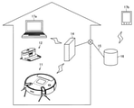
図1ないし図4において、11は電気掃除機であり、この電気掃除機11は、この電気掃除機11の充電用の基地部となる基地装置としての充電装置(充電台)12(図4)とともに電気掃除装置(電気掃除システム)を構成するものである。そして、電気掃除機11は、本実施形態において、走行面としての被掃除面である床面上を自律走行(自走)しつつ床面を掃除する、いわゆる自走式のロボットクリーナ(掃除ロボット)であり、例えば掃除領域内などに配置された中継手段(中継部)としてのホームゲートウェイ(ルータ)14との間で有線通信あるいはWi-Fi(登録商標)やBluetooth(登録商標)などの無線通信を用いて通信(送受信)することにより、インターネットなどの(外部)ネットワーク15を介して、データ格納手段(データ格納部)としての汎用のサーバ16や、表示手段(表示部)である汎用の外部装置17などと有線あるいは無線通信可能となっている。
In FIGS. 1 to 4, 11 is a vacuum cleaner, and the
また、この電気掃除機11は、中空状の本体ケース20と、この本体ケース20を床面上で走行させる走行部21と、床面などの塵埃を掃除する掃除部22と、充電装置12を含む外部装置と通信する通信部23と、画像を撮像する撮像部25と、センサ部26と、走行部21、掃除部22、通信部23、および、撮像部25などを制御するコントローラである制御手段(制御部)27と、これら走行部21、掃除部22、通信部23、撮像部25、センサ部26および制御手段27などに給電する二次電池28とを備えている。なお、以下、電気掃除機11(本体ケース20)の走行方向に沿った方向を前後方向(図2に示す矢印FR,RR方向)とし、この前後方向に対して交差(直交)する左右方向(両側方向)を幅方向として説明する。
Further, the
本体ケース20は、例えば合成樹脂などにより扁平な円柱状(円盤状)などに形成されている。すなわち、この本体ケース20は、側面部20aと、この側面部20aの上部および下部にそれぞれ連続する上面部20b(図2)および下面部20c(図3)とを備えている。この本体ケース20の側面部20aは、略円筒面状に形成されており、この側面部20aには、例えば撮像部25などが配置されている。また、本体ケース20の上面部20bおよび下面部20cは、それぞれ略円形状に形成されており、図3に示すように、床面に対向する下面部20cには、集塵口である吸込口31、および、排気口32などがそれぞれ開口されている。
The
走行部21は、複数(一対)の駆動部としての駆動輪34,34、これら駆動輪34,34を駆動させる動作部としての駆動手段であるモータ35,35(図1)、および、旋回用の旋回輪36などを備えている。
The
各駆動輪34は、電気掃除機11(本体ケース20)を床面上で前進方向および後退方向に走行(自律走行)させる、すなわち走行用のものであり、左右幅方向に沿って図示しない回転軸を有し、幅方向に対称に配置されている。
Each
各モータ35(図1)は、例えば駆動輪34のそれぞれに対応して配置されており、各駆動輪34を独立して駆動させることが可能となっている。
Each motor 35 (FIG. 1) is arranged corresponding to each of the
旋回輪36は、本体ケース20の下面部20cの幅方向の略中央部で、かつ、前部に位置しており、床面に沿って旋回可能な従動輪である。
The
掃除部22は、例えば本体ケース20内に位置して塵埃を吸込口31から空気とともに吸い込み排気口32から排気する電動送風機41、吸込口31に回転可能に取り付けられて塵埃を掻き上げる回転清掃体としての回転ブラシ42およびこの回転ブラシ42を回転駆動させるブラシモータ43(図1)、本体ケース20の前側などの両側に回転可能に取り付けられて塵埃を掻き集める旋回清掃部としての補助掃除手段(補助掃除部)であるサイドブラシ44およびこのサイドブラシ44を駆動させるサイドブラシモータ45(図1)、および、吸込口31と連通して塵埃を溜める集塵部46(図2)などを備えている。なお、電動送風機41と、回転ブラシ42およびブラシモータ43(図1)と、サイドブラシ44およびサイドブラシモータ45(図1)とは、少なくともいずれかを備えていればよい。
The
図1に示す通信部23は、ホームゲートウェイ14およびネットワーク15を介して外部装置17と無線通信をするための無線通信手段(無線通信部)および掃除機信号受信手段(掃除機信号受信部)としての無線LANデバイス47、充電装置12(図4)などへと無線信号(赤外線信号)を送信する例えば赤外線発光素子などの図示しない送信手段(送信部)、および、充電装置12や図示しないリモコンなどからの無線信号(赤外線信号)を受信する例えばフォトトランジスタなどの図示しない受信手段(受信部)などを備えている。なお、例えば通信部23にアクセスポイント機能を搭載し、ホームゲートウェイ14を介さずに外部装置17と直接無線通信をするようにしてもよい。また、例えば通信部23にウェブサーバ機能を付加してもよい。
The
無線LANデバイス47は、電気掃除機11からホームゲートウェイ14を介してネットワーク15に対して各種情報を送受信するものである。
The
撮像部25は、複数、例えば一方および他方の撮像手段(撮像部本体)としてのカメラ51a,51b、および、これらカメラ51a,51bに照明を付与する照明手段(照明部)としてのLEDなどのランプ53を備えている。
The
図2に示すように、カメラ51a,51bは、本体ケース20の側面部20aにおいて、前部の両側に配置されている。すなわち、本実施形態では、カメラ51a,51bは、本体ケース20の側面部20aにおいて、電気掃除機11(本体ケース20)の幅方向の中心線Lに対して、左右方向に略等しい所定角度(鋭角)傾斜した位置にそれぞれ配置されている。言い換えると、これらカメラ51a,51bは、本体ケース20に対して幅方向に略対称に配置されており、これらカメラ51a,51bの中心位置が、電気掃除機11(本体ケース20)の走行方向である前後方向と交差(直交)する幅方向の中心位置と略一致している。さらに、これらカメラ51a,51bは、上下方向に略等しい位置、すなわち略等しい高さ位置にそれぞれ配置されている。このため、これらカメラ51a,51bは、電気掃除機11を床面上に載置した状態でこの床面からの高さが互いに略等しく設定されている。したがって、カメラ51a,51bは、互いにずれた位置(左右方向にずれた位置)に離間されて配置されている。また、これらカメラ51a,51bは、本体ケース20の走行方向である前方を、それぞれ所定の水平画角(例えば105°など)でデジタルの画像を所定時間毎、例えば数十ミリ秒毎などの微小時間毎、あるいは数秒毎などに撮像するデジタルカメラである。さらに、これらカメラ51a,51bは、互いの撮像範囲(視野)Va,Vbが重なっており(図5)、これらカメラ51a,51bにより撮像される(一方および他方の)画像P1,P2(図6(a)および図6(b))は、その撮像領域が電気掃除機11(本体ケース20)の幅方向の中心線Lを延長した前方の位置を含む領域で左右方向にラップしている。本実施形態では、これらカメラ51a,51bは、例えば可視光領域の画像を撮像するものとする。なお、これらカメラ51a,51bにより撮像した画像は、例えば図示しない画像処理回路などにより所定のデータ形式に圧縮することもできる。
As shown in FIG. 2, the
ランプ53は、カメラ51a,51bにより画像を撮像する際の照明用の光を出力するもので、カメラ51a,51bの中間位置、すなわち本体ケース20の側面部20aの中心線L上の位置に配置されている。すなわち、ランプ53は、カメラ51a,51bからの距離が略等しくなっている。また、このランプ53は、カメラ51a,51bと上下方向に略等しい位置、すなわち略等しい高さ位置に配置されている。したがって、このランプ53は、カメラ51a,51bの幅方向の略中央部に配置されている。本実施形態では、このランプ53は、可視光領域を含む光を照明するようになっている。
The
図1に示すセンサ部26は、例えば各駆動輪34(各モータ35)の回転数を検出する光エンコーダなどの回転数センサ55を備えている。この回転数センサ55は、測定した駆動輪34(図3)またはモータ35の回転数によって、電気掃除機11(本体ケース20(図3))の旋回角度や進行距離を検出するようになっている。したがって、この回転数センサ55は、例えば充電装置12(図4)などの基準位置からの電気掃除機11(本体ケース20(図3))の相対位置を検出する、位置検出センサである。
The
制御手段27は、例えば制御手段本体(制御部本体)であるCPU、このCPUによって読み出されるプログラムなどの固定的なデータを格納した格納部であるROM、プログラムによるデータ処理の作業領域となるワークエリアなどの各種メモリエリアを動的に形成するエリア格納部であるRAM(それぞれ図示せず)などを備えるマイコンである。この制御手段27は、さらに、例えばカメラ51a,51bで撮像した画像のデータなどを記憶する記憶手段(記憶部)としてのメモリ61、カメラ51a,51bで撮像した画像に基づいてカメラ51a,51bからの物体(特徴点)の距離(深度)を計算し、この計算した物体の距離に基づいて距離画像を生成する距離画像生成手段(距離画像生成部)としての画像生成部62、この画像生成部62により生成した距離画像中に撮像された物体の形状を取得する形状取得手段としての形状取得部63、この形状取得部63により取得した物体の形状に応じて制御を判定する判定手段としての判定部64、および、判定部64による障害物判定に基づいて掃除領域のマップを生成するマップ生成手段(マップ生成部)としての画像処理部65などを備えている。また、この制御手段27は、走行部21のモータ35,35(駆動輪34,34(図3))の動作を制御する走行制御部66、掃除部22の電動送風機41、ブラシモータ43およびサイドブラシモータ45の動作を制御する掃除制御部67、撮像部25のカメラ51a,51bを制御する撮像制御部68、および、撮像部25のランプ53を制御する照明制御部69などを備えている。そして、この制御手段27は、例えば駆動輪34,34(図3)すなわちモータ35,35を駆動して電気掃除機11(本体ケース20(図3))を自律走行させる走行モードと、充電装置12(図4)を介して二次電池28を充電する充電モードと、動作待機中の待機モードとを有している。
The control means 27 is, for example, a CPU that is a control means main body (control unit main body), a ROM that is a storage unit that stores fixed data such as a program read by the CPU, and a work area that is a work area for data processing by the program. It is a microcomputer equipped with a RAM (not shown) which is an area storage unit that dynamically forms various memory areas such as. The control means 27 is further, for example, from the
メモリ61は、電気掃除機11の電源のオンオフに拘らず記憶した各種データを保持する、例えばフラッシュメモリなどの不揮発性のメモリである。
The
画像生成部62は、既知の方法を用いて、カメラ51a,51bにより撮像した画像と、カメラ51a,51b間の距離とに基づいて物体(特徴点)の距離を計算するとともに、この計算した物体(特徴点)の距離を示す距離画像を生成する。すなわち、この画像生成部62は、例えばカメラ51a,51bと物体(特徴点)Oとの距離、および、カメラ51a,51b間の距離に基づく三角測量を応用し(図5)、カメラ51a,51bにより撮像した各画像中から同一位置を示す画素ドットを検出し、この画素ドットの上下方向および左右方向の角度を計算して、これら角度とカメラ51a,51b間の距離とからその位置のカメラ51a,51bからの距離を計算する。したがって、カメラ51a,51bにより撮像する画像は、可能な限り範囲が重なって(ラップして)いることが好ましい。また、この画像生成部62による距離画像の生成は、計算した各画素ドットの距離を、例えば1ドット毎などの所定ドット毎に明度、あるいは色調などの、視認により識別可能な階調に変換して表示することにより行われる。本実施形態において、画像生成部62は、距離が大きいほど明度が小さい白黒の画像、すなわち電気掃除機11(本体ケース20)からの前方への距離が遠いほど黒く距離が近いほど白い、例えば256階調(8ビット=28)のグレースケールの画像として距離画像を生成する。したがって、この距離画像は、いわば電気掃除機11(本体ケース20)の走行方向前方のカメラ51a,51bによって撮像される範囲内に位置する物体の距離情報(距離データ)の集合体を可視化したものである。なお、この画像生成部62は、カメラ51a,51bにより撮像された各画像中の所定の画像範囲内の画素ドットについてのみの距離画像を生成してもよいし、画像全体の距離画像を生成してもよい。この画像範囲は、例えば電気掃除機11(本体ケース20)の走行速度などの条件に応じて変化させてもよいが、少なくともカメラ51a,51bから所定の距離D、あるいは所定の距離範囲DR(図5)内の所定位置(例えば距離範囲DR(図5)のうちの最も近い位置)に電気掃除機11(本体ケース20)が位置する場合の、この電気掃除機11(本体ケース20)の外形形状(上下左右の大きさ)以上とすることが好ましい。
The
形状取得部63は、画像生成部62により生成された距離画像に対して、所定の距離D、または、所定の距離範囲DRを設定することで、この距離D、または、距離範囲DRに位置する物体Oの形状情報を取得するものである(図5)。具体的に、この形状取得部63は、距離画像中の一例として、距離画像PLに撮像された例えば空き缶などの物体Oに対して、所定の距離D、あるいは距離範囲DR(図5)での画素ドットの距離を検出することで、物体Oの水平方向の寸法すなわち幅寸法Wおよび上下方向の寸法すなわち高さ寸法Hを検出できる(図6(c))。この所定の距離D、あるいは所定の距離範囲DR(図5)は、例えば電気掃除機11(本体ケース20)の走行速度などに対応して設定されている。この所定の距離D、あるいは所定の距離範囲DR(図5)は、例えば電気掃除機11(本体ケース20)の走行速度などに対応して可変設定されるようにしてもよい。また、この形状取得部63は、物体の形状情報(幅寸法および高さ寸法)を取得することで、その物体が存在しない空間や穴部の形状情報(幅寸法および高さ寸法)などをも間接的に取得できる。例えば、図7に示すようなベッドなどの物体Oの形状情報を取得することで、天板部であるフットボード部FBと床面Fとの上下方向の間隔G1、および、フットボード部FBから互いに離間されて床面Fに向けて突出する脚部LPの水平方向の間隔G2を間接的に取得できるので、これら脚部LP,LP間に区画される狭所(穴部)NSが位置しているかどうか、および、この狭所NSの形状情報(幅寸法および高さ寸法)を取得できる。
The
判定部64は、形状取得部63により取得した所定の距離、あるいは所定の距離範囲の物体の形状情報、および、物体間に位置する狭所などの形状情報に基づいて、物体が走行の妨げになる障害物であるか否か、あるいは、物体が乗り上げ可能なものであるか否かなどを判定するとともに、電気掃除機11(本体ケース20)の走行制御の変更の要否を判定する。この判定部64は、さらに、形状取得部63により取得した所定の距離、あるいは所定の距離範囲の物体の形状情報、および、物体間に位置する狭所などの形状情報に基づいて、掃除制御の変更の要否を判定してもよい。これらの判定の詳細は後述する。
The
画像処理部65は、形状取得部63により取得した物体の形状情報と、センサ部26の回転数センサ55により検出した電気掃除機11(本体ケース20)の位置とから、電気掃除機11(本体ケース20)が配置された掃除領域およびこの掃除領域内に位置する物体などの位置関係を計算してマップを生成する。なお、この画像処理部65は、必須の構成ではない。
The
走行制御部66は、モータ35,35に流れる電流の大きさおよび向きを制御することにより、モータ35,35を正転、あるいは逆転させることで、モータ35,35の駆動を制御し、これらモータ35,35の駆動を制御することで駆動輪34,34(図3)の駆動を制御している。また、この走行制御部66は、判定部64の判定に応じて、電気掃除機11(本体ケース20)の走行方向および/または走行速度を制御するように構成されている。
The
掃除制御部67は、電動送風機41、ブラシモータ43、および、サイドブラシモータ45をそれぞれ別個に導通角制御することで、これら電動送風機41、ブラシモータ43(回転ブラシ42(図3))、および、サイドブラシモータ45(サイドブラシ44(図3))の駆動を制御している。また、この掃除制御部67は、判定部64の判定に応じて、掃除部22の動作を制御するように構成されている。なお、これら電動送風機41、ブラシモータ43、および、サイドブラシモータ45のそれぞれに対応して制御部を別個に設けてもよい。
The
撮像制御部68は、カメラ51a,51bのシャッタの動作を制御する制御回路を備え、このシャッタを所定時間毎に動作させることで、所定時間毎にカメラ51a,51bにより画像を撮像させるように制御する。
The image
照明制御部69は、スイッチなどを介してランプ53のオンオフを制御している。この照明制御部69は、本実施形態では、電気掃除機11の周囲の明るさを検出するセンサを備えており、このセンサにより検出した明るさが所定以下の場合にランプ53を点灯させ、その他のときにはランプ53を点灯させないようにするものである。
The
また、二次電池28は、例えば図3に示す本体ケース20の下面部20cの後部の両側に露出する接続部としての充電端子71,71と電気的に接続されており、これら充電端子71,71が充電装置12(図4)側と電気的および機械的に接続されることで、この充電装置12(図4)を介して充電されるようになっている。
Further, the
図1に示すホームゲートウェイ14は、アクセスポイントなどとも呼ばれ、建物内に設置され、ネットワーク15に対して例えば有線により接続されている。
The
サーバ16は、ネットワーク15に接続されたコンピュータ(クラウドサーバ)であり、各種データを保存可能である。
The
外部装置17は、建物の内部では例えばホームゲートウェイ14を介してネットワーク15に対して有線あるいは無線通信可能であるとともに、建物の外部ではネットワーク15に対して有線あるいは無線通信可能な、例えばPC(タブレット端末(タブレットPC))17aやスマートフォン(携帯電話)17bなどの汎用のデバイスである。この外部装置17は、少なくとも画像を表示する表示機能を有している。
The
次に、上記一実施形態の動作を説明する。 Next, the operation of the above embodiment will be described.
一般に、電気掃除装置は、電気掃除機11によって掃除をする掃除作業と、充電装置12によって二次電池28を充電する充電作業とに大別される。充電作業は、充電装置12に内蔵された定電流回路などの充電回路を用いる既知の方法が用いられるため、掃除作業についてのみ説明する。また、外部装置17などからの指令に応じてカメラ51a,51bの少なくともいずれかにより所定の対象物を撮像する撮像作業を別途備えていてもよい。
Generally, the electric cleaning device is roughly classified into a cleaning work of cleaning by the
電気掃除機11は、例えば予め設定された掃除開始時刻となったときや、リモコンまたは外部装置17によって送信された掃除開始の指令信号を受信したときなどのタイミングで、制御手段27が待機モードから走行モードに切り換わり、この制御手段27(走行制御部66)がモータ35,35(駆動輪34,34)を駆動させ充電装置12から所定距離離脱する。
In the
次いで、電気掃除機11は、画像処理部65により、掃除領域のマップを生成する。このマップの生成の際には、概略として、電気掃除機11は、掃除領域の外壁などに沿って走行したり、その位置で旋回したりしながら、カメラ51a,51bにより撮像した画像中の物体の距離を計算し、この距離から壁や障害物を判定して、現在の電気掃除機11の位置に基づいてマップを生成する(マップ生成モード)。そして、制御手段27が、掃除領域全体をマッピングしたと判定した場合には、マップ生成モードを終了し、後述する掃除モードに移行する。なお、このマップは、生成時に例えばメモリ61などに一旦記憶しておけば、次回の掃除以降はメモリ61から読み出すだけでもよく、掃除の都度生成する必要はないが、メモリ61に記憶しているマップと異なる掃除領域を掃除する場合や、同じ掃除領域でも物体のレイアウトなどが変わっている場合もあるので、例えばユーザの指令などに応じて、あるいは所定期間毎などに適宜生成できるようにしてもよいし、一旦生成したマップを、掃除作業のときの物体の距離測定に基づいて随時更新してもよい。
Next, the
次いで、電気掃除機11は、生成したマップに基づいて、掃除領域内を自律走行しつつ掃除をする(掃除モード)。この自律走行の際には、概略として、電気掃除機11は、前進しながら、カメラ51a,51bにより撮像した画像中の物体の距離を計算し、この距離やマッピングしたマップに基づいて壁や障害物を判定して、これら壁や障害物を回避しながら走行しつつ、掃除部22によって掃除を行う。
Next, the
より詳細に、図8に示すフローチャートなども参照しながら説明すると、まず、制御手段27(走行制御部66)によりモータ35,35(駆動輪34,34)を駆動させて電気掃除機11(本体ケース20)を走行させ(ステップ1)、制御手段27(撮像制御部68)により駆動させたカメラ51a,51bにより走行方向前方を撮像する(ステップ2)。これら撮像した画像の少なくともいずれかは、メモリ61に記憶することができる。次に、これらカメラ51a,51bにより撮像した画像と、カメラ51a,51bとの間の距離に基づき、画像生成部62により所定の画像範囲内の物体(特徴点)の距離を計算する(ステップ3)。具体的に、例えばカメラ51a,51bにより図6(a)および図6(b)に示すような画像P1,P2を撮像した場合、その画像P1,P2中の各画素ドットの距離を画像生成部62により計算する。さらに、画像生成部62は、計算した距離に基づいて距離画像を生成する(ステップ4)。この距離画像も、例えばメモリ61に記憶することができる。この画像生成部62により生成した距離画像PLの例を図6(c)に示す。そして、この生成した距離画像から、形状取得部63が、所定の距離、あるいは所定の距離範囲の物体の形状情報を取得する(ステップ5)。このとき、物体の形状情報として、幅寸法、高さ寸法などを検出することで、狭所の形状情報なども取得できる。
To explain in more detail with reference to the flowchart shown in FIG. 8, first, the
そして、判定部64が、形状取得部63により取得した物体の形状情報に基づき、電気掃除機11(本体ケース20)の前方の所定の距離、あるいは所定の距離範囲内に物体があるか否かを判定する(ステップ6)。具体的に、判定部64は、形状取得部63により取得した物体の幅寸法および高さ寸法、物体間の水平方向あるいは上下方向の間隔に基づき、距離画像の所定の画像範囲内に物体の少なくとも一部が位置しているか否かを判定する。この画像範囲は、カメラ51a,51bから所定の距離D、あるいは所定の距離範囲DR内の所定位置(例えば距離範囲DRのうち最も近い位置)に電気掃除機11(本体ケース20)が位置する場合の、この電気掃除機11(本体ケース20)の外形形状(上下左右の大きさ)に対応する。したがって、この画像範囲内にて所定の距離、あるいは所定の距離範囲内に障害物が位置することは、電気掃除機11(本体ケース20)がこのまま前進したときに電気掃除機11(本体ケース20)の軌跡内に物体が位置することを意味する。
Then, based on the shape information of the object acquired by the
このステップ6において、物体がないと判定した場合、電気掃除機11(本体ケース20)の前方に走行可能なスペースがあるものと想定されるので、判定部64は、形状取得部63により取得した物体の形状情報に基づき、このスペースが大きいか否か、すなわち電気掃除機11(本体ケース20)の前方に狭所があるか否かを判定する(ステップ7)。具体的に、判定部64は、形状取得部63により取得した物体間の水平方向の間隔および物体間の上下方向の間隔がそれぞれ所定の範囲内であるときに、狭所が位置していると判定する。より詳細に、判定部64は、形状取得部63により取得した物体間の水平方向および上下方向のそれぞれの間隔と、電気掃除機11(本体ケース20)の幅寸法および高さ寸法との差の少なくともいずれかが所定値未満であるときに、狭所が位置していると判定する。そして、制御手段27(走行制御部66)は、この判定に応じて、電気掃除機11(本体ケース20)の走行速度を制御する。
If it is determined in this
具体的に、ステップ7において、電気掃除機11(本体ケース20)の前方に狭所がない(上記の差がそれぞれ所定値未満でない(所定値以上である))と判定した場合には、電気掃除機11(本体ケース20)の前方に充分なスペースがある、または、電気掃除機11(本体ケース20)の前方に物体がないと想定されるため、電気掃除機11(本体ケース20)の走行速度を相対的に高速の第1速度に設定し(ステップ8)、ステップ1に戻る。このステップ8の走行制御としては、制御手段27(走行制御部66)が、電気掃除機11(本体ケース20)の走行速度が第1速度となるようにモータ35,35(駆動輪34,34)の駆動を制御する。したがって、電気掃除機11(本体ケース20)が既に第1速度で走行している場合には、走行速度を変更せずにステップ1に戻る。
Specifically, in
また、ステップ7において、電気掃除機11(本体ケース20)の前方に狭所がある(上記の差の少なくともいずれかが所定値未満である)と判定した場合には、電気掃除機11(本体ケース20)の前方の狭所に電気掃除機11(本体ケース20)が入り込めると想定されるため、電気掃除機11(本体ケース20)の走行速度を相対的に低速の第2速度に設定し(ステップ9)、ステップ1に戻る。このステップ9の走行制御としては、制御手段27(走行制御部66)が、電気掃除機11(本体ケース20)の走行速度が第2速度となるようにモータ35,35(駆動輪34,34)の駆動を制御することで、電気掃除機11(本体ケース20)の外形に対して余裕が少ない、ぎりぎりの形状である狭所に、この狭所を囲む物体と衝突しないように慎重に走行しながら確実に入り込めるようにする。したがって、電気掃除機11(本体ケース20)が既に第2速度で走行している場合には、走行速度を変更せずにステップ1に戻る。
Further, in
一方、ステップ6において、物体があると判定した場合、電気掃除機11(本体ケース20)の前方の物体が、走行の妨げとなる障害物である場合と、走行の妨げにならない物体である場合とが想定されるため、判定部64は、形状取得部63により取得した物体の形状情報に基づき、物体は障害物であるか否かを判定する(ステップ10)。具体的に、判定部64は、形状取得部63により取得した物体の高さ寸法に基づき、物体が障害物であるか否かを判定する。より詳細に、判定部64は、形状取得部63により取得した物体の高さ寸法が所定の高さ以上である場合に、物体が障害物であると判定する。この所定の高さは、例えば電気掃除機11(本体ケース20)が乗り上げてもスタックしない高さに設定されている。
On the other hand, when it is determined in
そして、このステップ10において、物体は障害物でない(物体の高さ寸法が所定の高さ寸法未満である)と判定した場合には、物体が例えば玄関マットや掃除領域の一部に配置された絨毯やカーペットなど、比較的高さが小さく乗り上げ可能な物体であるものと想定されるため、判定部64は、制御手段27(掃除制御部67)による掃除制御を変更し(ステップ11)、ステップ1に戻って物体を回避せずに物体に乗り上げる。このステップ11の掃除制御の変更としては、例えば掃除部22の電動送風機41の入力の増減、回転ブラシ42(ブラシモータ43)および/またはサイドブラシ44,44(サイドブラシモータ45,45)の駆動のオンオフあるいは駆動速度を制御手段27(掃除制御部67)により変更する。例えば、このステップ10においては、電動送風機41の入力を増加させ、回転ブラシ42(ブラシモータ43)の駆動速度を増加させることでごみ取れを向上する。なお、この掃除制御の変更は、例えば物体の高さ寸法に複数の閾値を設定し、物体の高さ寸法が大きい(厚い)場合と、物体の高さ寸法が小さい(薄い)場合とで、異なる制御としてもよい。
Then, in this
一方、ステップ10において、物体は障害物である(物体の高さ寸法が所定の高さ寸法未満である)と判定した場合には、電気掃除機11(本体ケース20)の前方に回避すべき物体や入り込めない狭所が位置しているものと想定され、判定部64は、制御手段27(走行制御部66)による電気掃除機11(本体ケース20)の走行方向を変更し(ステップ12)、ステップ1に戻る。この走行方向の変更としては、形状取得部63により取得した物体の形状情報に基づき、その形状情報に応じて適宜走行方向を変えて回避動作したり、予め設定された単数、または複数の所定の回避動作ルーチンを選択したりすることができる。回避動作としては、例えば制御手段27(走行制御部66)がモータ35,35(駆動輪34,34)の駆動を制御して、電気掃除機11(本体ケース20)を物体に対して一旦停止させ、その位置、あるいは所定距離後退した位置で旋回することで、図9(a)に示すように物体Oをクランク状に回避したり(物体Oが比較的小さい場合)、図9(b)、図9(c)に示すように物体Oから離反する方向に走行あるいは物体Oに沿って走行したり(物体Oが壁などの場合)する。
On the other hand, if it is determined in
この結果、電気掃除機11(本体ケース20)は、掃除領域内の床面上を、障害物を回避しながら狭所NS(図7)など隅々に至るまで自律走行しつつ掃除部22を制御手段27(掃除制御部67)により動作させて床面の塵埃を掃除する。すなわち、電気掃除機11は、障害物を検出しても掃除作業を継続するなど、継続した動作を行う。
As a result, the vacuum cleaner 11 (main body case 20) autonomously travels on the floor surface in the cleaning area to every corner such as a narrow space NS (Fig. 7) while avoiding obstacles while cleaning the
掃除部22では、制御手段27(掃除制御部67)により駆動された電動送風機41、回転ブラシ42(ブラシモータ43)、あるいはサイドブラシ44(サイドブラシモータ45)により床面の塵埃を、吸込口31を介して集塵部46へと捕集する。そして、マップした掃除領域の掃除が完了した場合、あるいは掃除作業中に二次電池28の容量が所定量まで低下して掃除や撮像を完了させるのに不足している(二次電池28の電圧が放電終止電圧近傍まで低下している)などの所定条件時には、電気掃除機11では、充電装置12に帰還するように制御手段27(走行制御部66)によってモータ35,35(駆動輪34,34)の動作を制御する。この後、充電端子71,71と充電装置12の充電用端子とが接続されると、掃除作業を終了し、制御手段27が待機モード、あるいは充電モードに移行する。
In the
なお、メモリ61に記憶した画像のデータは、例えば電気掃除機11が充電装置12に帰還したとき、掃除作業中に随時、所定時間毎、あるいは外部装置17からの要求があったときなどに無線LANデバイス47を介してホームゲートウェイ14およびネットワーク15を経由してサーバ16に送信する。なお、送信が終了したデータは、メモリ61から消去、あるいは新たなデータを記憶する際に上書きすることで、メモリ61の容量を効率よく使用できる。
The image data stored in the
サーバ16では、電気掃除機11から送信された画像のデータを保存し、外部装置17からの要求(アクセス)に応じてそれら画像のデータをダウンロード可能となっている。
The
そして、外部装置17では、サーバ16からダウンロードされた画像が表示される。
Then, the
以上説明した一実施形態によれば、カメラ51a,51bによって撮像した画像により、電気掃除機11(本体ケース20)の走行方向側に位置する物体の距離画像を画像生成部62により生成し、この生成した距離画像から、撮像された物体の形状情報を形状取得部63により取得することで、物体の有無だけでなく、物体の形状をも精度よく検出できる。
According to the embodiment described above, the
また、形状取得部63により、電気掃除機11(本体ケース20)の走行方向側に位置する物体の水平方向の間隔を取得することで、水平方向に電気掃除機11(本体ケース20)が入り込めるスペースがあるか否かを容易に判定できる。
Further, the
同様に、形状取得部63により、電気掃除機11(本体ケース20)の走行方向側に位置する物体の上下方向の間隔を取得することで、上下方向に電気掃除機11(本体ケース20)が入り込めるスペースがあるか否かを容易に判定できる。
Similarly, the
このため、これら水平方向および上下方向の間隔の取得などの形状情報に基づき、形状取得部63により、電気掃除機11(本体ケース20)の前方に狭所NS(図7)が位置しているか否かを取得することで、電気掃除機11(本体ケース20)がベッドなどの物体O(図7)の下部の脚部LP,LP間や、椅子などの物体の脚部の間などに入り込ませるように走行制御できる。
Therefore, based on the shape information such as the acquisition of the horizontal and vertical intervals, is the narrow space NS (FIG. 7) located in front of the vacuum cleaner 11 (main body case 20) by the
そして、制御手段27が、形状取得部63により取得した形状情報に応じて電気掃除機11(本体ケース20)の走行を制御するようにモータ35,35(駆動輪34,34)の動作を制御することで、走行の妨げになる障害物などを、衝突する前に未然に回避して、しかも障害物を必要以上に大きく回避することなく、障害物の近傍に沿わせて電気掃除機11(本体ケース20)を走行させることができ、走行性能を向上できる。このため、掃除領域の中を隅々まで掃除でき、掃除性能を向上できる。
Then, the control means 27 controls the operation of the
具体的に、制御手段27が、形状取得部63により取得した物体の形状情報に応じて電気掃除機11(本体ケース20)の走行速度を制御するようにモータ35,35(駆動輪34,34)の動作を制御することで、例えば電気掃除機11(本体ケース20)の前方に比較的スペースが大きい、すなわち走行の妨げになる障害物がない場合には、電気掃除機11(本体ケース20)を相対的に高速で走行させて効率よく掃除できるとともに、電気掃除機11(本体ケース20)が狭所NS(図7)に入り込む際に、この狭所NS(図7)の幅寸法や高さ寸法が電気掃除機11(本体ケース20)の外形ぎりぎりの形状である場合などには、電気掃除機11(本体ケース20)を相対的に低速で走行させて狭所NSに入り込みやすくすることなども可能になる。
Specifically, the
同様に、制御手段27が、形状取得部63により取得した物体の形状情報に応じて電気掃除機11(本体ケース20)の走行方向を制御するようにモータ35,35(駆動輪34,34)の動作を制御することで、例えば電気掃除機11(本体ケース20)の前方に位置する障害物の形状に応じてその回避動作を異ならせることなども可能になる。
Similarly, the
したがって、物体の形状に適した電気掃除機11(本体ケース20)の走行制御が可能になる。 Therefore, it is possible to control the running of the vacuum cleaner 11 (main body case 20) suitable for the shape of the object.
また、形状取得部63により、距離画像から得られた所定の距離において、物体の形状情報を取得する場合には、電気掃除機11(本体ケース20)が現在の位置から所定の距離の位置まで走行したときに、この所定の距離に位置する物体に対して電気掃除機11(本体ケース20)が衝突しないように走行制御することが可能になる。
Further, when the
さらに、形状取得部63により、距離画像から得られた所定の距離範囲において、物体の形状を取得する場合には、電気掃除機11(本体ケース20)が現在の位置から所定の距離範囲内に前部が位置するまで走行したときに、この距離範囲内に位置する物体に対して電気掃除機11(本体ケース20)が衝突しないよう走行制御することが可能になる。
Further, when the
また、制御手段27が、形状取得部63により取得した物体の形状情報に応じて掃除部22の動作を制御することで、形状取得部63により取得した物体の形状情報から、電気掃除機11(本体ケース20)が例えば絨毯やカーペットなどに乗り上げると判定した際などの、床面の種類が変化すると判定した場合に、その床面に適した掃除状態とすることができ、掃除効率を向上できる。
Further, the control means 27 controls the operation of the
なお、上記一実施形態において、形状取得部63により取得した物体の形状情報に基づく制御手段27(走行制御部66)による電気掃除機11(本体ケース20)の走行制御は、上記の形態に限らず、物体の形状に対応させて任意に設定できる。
In the above embodiment, the travel control of the vacuum cleaner 11 (main body case 20) by the control means 27 (travel control unit 66) based on the shape information of the object acquired by the
また、カメラ51a,51bを本体ケース20(側面部20a)の左右方向に略等しい位置、すなわち上下に配置することもできる。
Further, the
さらに、カメラ51a,51bの少なくともいずれかを、赤外領域の画像を撮像する、赤外線カメラとすることもできる。
Further, at least one of the
また、画像の表示は、制御手段27によって外部装置17で表示可能となるように処理する構成の他に、例えばそれぞれ外部装置17にインストールされた専用のプログラム(アプリケーション)により外部装置17で表示するように処理することもできるし、制御手段27、あるいはサーバ16で予め処理をしておき、外部装置17のブラウザなどの汎用のプログラムにより表示することもできる。すなわち、表示制御手段(表示制御部)としては、サーバ16に保存されたプログラムや、外部装置17にインストールされたプログラムなどにより画像を表示させる構成とすることもできる。
In addition to the configuration in which the control means 27 processes the image so that it can be displayed on the
さらに、メモリ61に一時記憶した画像などのデータは、サーバ16に送信してサーバ16に記憶するようにしたが、メモリ61にそのまま記憶しておいてもよいし、外部装置17に記憶しておいてもよい。
Further, data such as images temporarily stored in the
また、カメラ51a,51bで撮像した画像や画像生成部62で生成した距離画像は、外部装置17に限らず、例えば電気掃除機11自体に設けた表示部などに表示することもできる。この場合には、メモリ61からサーバ16へとホームゲートウェイ14およびネットワーク15経由でデータを送信しなくてもよく、電気掃除機11の構成や制御をより簡略化することもできる。
Further, the image captured by the
そして、画像生成部62、形状取得部63、判定部64、掃除制御部67、撮像制御部68および照明制御部69はそれぞれ制御手段27中に備えたが、それぞれ互いに別構成としてもよいし、いずれか2つ以上を任意に組み合わせてもよい。
The
さらに、画像生成部62による距離計算は、掃除作業時だけでなく、電気掃除機11(本体ケース20)の任意の走行時にも用いることができる。
Further, the distance calculation by the
また、撮像手段は、3つ以上設定されていてもよい。すなわち、撮像手段は、複数であれば、その個数は限定されない。 Further, three or more image pickup means may be set. That is, if there are a plurality of image pickup means, the number thereof is not limited.
本発明の一実施形態を説明したが、この実施形態は、例として提示したものであり、発明の範囲を限定することは意図していない。この新規な実施形態は、その他の様々な形態で実施されることが可能であり、発明の要旨を逸脱しない範囲で、種々の省略、置き換え、変更を行うことができる。この実施形態やその変形は、発明の範囲や要旨に含まれるとともに、特許請求の範囲に記載された発明とその均等の範囲に含まれる。 Although one embodiment of the present invention has been described, this embodiment is presented as an example and is not intended to limit the scope of the invention. This novel embodiment can be implemented in various other embodiments, and various omissions, replacements, and changes can be made without departing from the gist of the invention. This embodiment and its modifications are included in the scope and gist of the invention, and are also included in the scope of the invention described in the claims and the equivalent scope thereof.
11 電気掃除機
20 本体ケース
22
掃除部
27 制御手段
34 駆動輪
51a,51b 撮像手段としてのカメラ
62 距離画像生成手段としての画像生成部
63 形状取得手段としての形状取得部
64 判定手段としての判定部
D 距離
DR 距離範囲
G1,G2 間隔
NS 狭所
11 Vacuum cleaner
20 Body case
22 Cleaning department
27 Control means
34 drive wheels
51a, 51b Camera as an imaging means
62 Image generation unit as a distance image generation means
63 Shape acquisition unit as a shape acquisition means
64 Judgment unit as a judgment means D Distance
DR range
G1, G2 interval
NS narrow space
Claims (2)
この本体ケースを走行可能とする駆動輪と、
この駆動輪の駆動を制御することで前記本体ケースを自律走行させる制御手段と、
塵埃を掃除する掃除部と、
前記本体ケースに配置されて互いに離間され、前記本体ケースの走行方向側を撮像する複数の撮像手段と、
これら撮像手段によって撮像した画像により、この走行方向側に位置する物体の距離画像を生成する距離画像生成手段と、
この距離画像生成手段で生成した距離画像に対して所定の距離または所定の距離範囲を設定して、前記所定の距離または前記所定の距離範囲に位置する物体の水平方向の間隔および上下方向の間隔を含む形状情報を取得する形状取得手段と、
前記形状取得手段により取得された前記物体の形状情報に基づき前記本体ケースの走行方向側に、前記物体の水平方向および上下方向の間隔と前記本体ケースの幅寸法および高さ寸法との差の少なくともいずれかが所定値未満である狭所が位置しているか否かを判定する判定手段とを具備し、
前記制御手段は、前記狭所が位置しているか否かに応じて前記本体ケースの走行速度と走行方向との少なくともいずれかを制御するように前記駆動輪の動作を制御する
ことを特徴とした電気掃除機。 With the main body case
The drive wheels that allow this body case to run,
A control means for autonomously traveling the main body case by controlling the drive of the drive wheels, and
A cleaning unit that cleans dust,
A plurality of imaging means arranged in the main body case and separated from each other to image the traveling direction side of the main body case, and
A distance image generation means that generates a distance image of an object located on the traveling direction side from the images captured by these imaging means, and a distance image generation means.
A predetermined distance or a predetermined distance range is set for the distance image generated by the distance image generation means, and the horizontal spacing and the vertical spacing of the objects located at the predetermined distance or the predetermined distance range are set. A shape acquisition means for acquiring shape information including
At least the difference between the horizontal and vertical spacing of the object and the width dimension and height dimension of the main body case on the traveling direction side of the main body case based on the shape information of the object acquired by the shape acquisition means. It is provided with a determination means for determining whether or not a narrow space where any of the values is less than a predetermined value is located.
The control means is characterized in that the operation of the drive wheels is controlled so as to control at least one of the traveling speed and the traveling direction of the main body case depending on whether or not the narrow space is located. Vacuum cleaner.
ことを特徴とした請求項1記載の電気掃除機。 The vacuum cleaner according to claim 1, wherein the control means controls the operation of the cleaning unit according to the shape information of the object acquired by the shape acquisition means.
Priority Applications (8)
| Application Number | Priority Date | Filing Date | Title |
|---|---|---|---|
| JP2015200186A JP7007078B2 (en) | 2015-10-08 | 2015-10-08 | Vacuum cleaner |
| US15/766,646 US20180289225A1 (en) | 2015-10-08 | 2016-10-03 | Vacuum cleaner |
| MYPI2018701384A MY191840A (en) | 2015-10-08 | 2016-10-03 | Vacuum cleaner |
| KR1020177010884A KR102003787B1 (en) | 2015-10-08 | 2016-10-03 | Electrical vacuum cleaner |
| PCT/JP2016/079290 WO2017061375A1 (en) | 2015-10-08 | 2016-10-03 | Electrical vacuum cleaner |
| EP16853529.2A EP3360454B1 (en) | 2015-10-08 | 2016-10-03 | Electrical vacuum cleaner |
| CN201680003520.5A CN107105958B (en) | 2015-10-08 | 2016-10-03 | Electric vacuum cleaner |
| TW105132117A TWI641349B (en) | 2015-10-08 | 2016-10-05 | Electric sweeper |
Applications Claiming Priority (1)
| Application Number | Priority Date | Filing Date | Title |
|---|---|---|---|
| JP2015200186A JP7007078B2 (en) | 2015-10-08 | 2015-10-08 | Vacuum cleaner |
Publications (2)
| Publication Number | Publication Date |
|---|---|
| JP2017070558A JP2017070558A (en) | 2017-04-13 |
| JP7007078B2 true JP7007078B2 (en) | 2022-01-24 |
Family
ID=58487629
Family Applications (1)
| Application Number | Title | Priority Date | Filing Date |
|---|---|---|---|
| JP2015200186A Active JP7007078B2 (en) | 2015-10-08 | 2015-10-08 | Vacuum cleaner |
Country Status (8)
| Country | Link |
|---|---|
| US (1) | US20180289225A1 (en) |
| EP (1) | EP3360454B1 (en) |
| JP (1) | JP7007078B2 (en) |
| KR (1) | KR102003787B1 (en) |
| CN (1) | CN107105958B (en) |
| MY (1) | MY191840A (en) |
| TW (1) | TWI641349B (en) |
| WO (1) | WO2017061375A1 (en) |
Families Citing this family (14)
| Publication number | Priority date | Publication date | Assignee | Title |
|---|---|---|---|---|
| KR20180134230A (en) * | 2017-06-08 | 2018-12-18 | 삼성전자주식회사 | Cleaning robot and controlling method of thereof |
| JP7065449B2 (en) * | 2018-07-20 | 2022-05-12 | パナソニックIpマネジメント株式会社 | Self-propelled vacuum cleaner |
| JP2020010981A (en) * | 2018-07-20 | 2020-01-23 | パナソニックIpマネジメント株式会社 | Self-propelled cleaner |
| JP2020110260A (en) * | 2019-01-09 | 2020-07-27 | 三菱電機株式会社 | Self-travelling cleaner |
| US10463217B1 (en) * | 2019-01-31 | 2019-11-05 | Irobot Corporation | Cleaning of pet areas by autonomous cleaning robots |
| US11191407B2 (en) | 2019-01-31 | 2021-12-07 | Irobot Corporation | Cleaning of pet areas by autonomous cleaning robots |
| CN111596651B (en) * | 2019-02-19 | 2022-08-09 | 科沃斯机器人股份有限公司 | Environmental area division and fixed-point cleaning method, equipment and storage medium |
| US11523722B2 (en) * | 2019-05-28 | 2022-12-13 | Pixart Imaging Inc. | Dirtiness level determining method and electronic device applying the dirtiness level determining method |
| US11493336B2 (en) | 2020-06-22 | 2022-11-08 | Pixart Imaging Inc. | Optical navigation device which can determine dirtiness level of cover or fix multi light pattern issue |
| CN110279350A (en) * | 2019-06-20 | 2019-09-27 | 深圳市银星智能科技股份有限公司 | From mobile device moving method and from mobile device |
| KR20210084129A (en) * | 2019-12-27 | 2021-07-07 | 삼성전자주식회사 | Robot cleaner and control method thereof |
| BR102021000321A2 (en) * | 2020-01-10 | 2021-07-27 | Bissell Inc. | AUTONOMOUS FLOOR CLEANER, AND METHOD FOR GETTING OUT OF A STAKED CONDITION PERFORMED BY AN AUTONOMOUS FLOOR CLEANER |
| CN113848872B (en) * | 2020-06-28 | 2024-03-15 | 苏州科瓴精密机械科技有限公司 | Automatic walking device, control method thereof and readable storage medium |
| WO2023145529A1 (en) * | 2022-01-31 | 2023-08-03 | ソニーグループ株式会社 | Information processing device, information processing method, and information processing program |
Citations (3)
| Publication number | Priority date | Publication date | Assignee | Title |
|---|---|---|---|---|
| JP2003304992A (en) | 2002-04-17 | 2003-10-28 | Hitachi Ltd | Self-running type vacuum cleaner |
| JP2006209644A (en) | 2005-01-31 | 2006-08-10 | Matsushita Electric Works Ltd | Cleaning robot |
| JP2006260105A (en) | 2005-03-16 | 2006-09-28 | Matsushita Electric Works Ltd | Moving apparatus |
Family Cites Families (26)
| Publication number | Priority date | Publication date | Assignee | Title |
|---|---|---|---|---|
| JP2003023699A (en) * | 2001-07-05 | 2003-01-24 | Saibuaasu:Kk | Spatial information auralizing system and spatial information auralizing method |
| CN1287722C (en) * | 2002-06-21 | 2006-12-06 | 泰怡凯电器(苏州)有限公司 | Method for identifying automatic dust collector cleanable area and obstacle area |
| KR100486506B1 (en) * | 2002-12-31 | 2005-04-29 | 엘지전자 주식회사 | Auto charge apparatus and method of robot cleaner in using image processing |
| DE102005046813A1 (en) * | 2005-09-30 | 2007-04-05 | Vorwerk & Co. Interholding Gmbh | Household appliance e.g. floor dust collecting device, operating method for room, involves arranging station units that transmit radio signals, in addition to base station, and orienting household appliance in room by processing signals |
| JP2007163223A (en) | 2005-12-12 | 2007-06-28 | Sharp Corp | Travel sensing system |
| JP2008090380A (en) * | 2006-09-29 | 2008-04-17 | Matsushita Electric Ind Co Ltd | Autonomous traveling device and program |
| JP4535096B2 (en) * | 2007-07-27 | 2010-09-01 | ソニー株式会社 | Planar extraction method, apparatus thereof, program thereof, recording medium thereof, and imaging apparatus |
| DE102008014912B4 (en) * | 2008-03-19 | 2023-01-19 | Vorwerk & Co. Interholding Gmbh | Automatically movable floor dust collector |
| DE102010017689A1 (en) * | 2010-07-01 | 2012-01-05 | Vorwerk & Co. Interholding Gmbh | Automatically movable device and method for orientation of such a device |
| KR101850386B1 (en) * | 2011-04-19 | 2018-04-19 | 엘지전자 주식회사 | Robot cleaner and controlling method of the same |
| TW201319853A (en) * | 2011-11-10 | 2013-05-16 | Univ Shu Te | Cloud-based clean monitoring system |
| KR20130090438A (en) * | 2012-02-04 | 2013-08-14 | 엘지전자 주식회사 | Robot cleaner |
| JP2013235351A (en) | 2012-05-07 | 2013-11-21 | Sharp Corp | Self-propelled electronic equipment |
| JP2013242738A (en) * | 2012-05-22 | 2013-12-05 | Sharp Corp | Robot device, terminal device, remote control system for robot device and program |
| KR101949277B1 (en) * | 2012-06-18 | 2019-04-25 | 엘지전자 주식회사 | Autonomous mobile robot |
| JP2014048842A (en) * | 2012-08-30 | 2014-03-17 | Brother Ind Ltd | Autonomous mobile device |
| JP6030405B2 (en) * | 2012-10-25 | 2016-11-24 | シャープ株式会社 | Planar detection device and autonomous mobile device including the same |
| DK2764812T3 (en) * | 2013-02-12 | 2015-08-24 | Hako Gmbh | Cleaning Robot. |
| JP6132659B2 (en) * | 2013-02-27 | 2017-05-24 | シャープ株式会社 | Ambient environment recognition device, autonomous mobile system using the same, and ambient environment recognition method |
| KR102071947B1 (en) * | 2013-05-10 | 2020-01-31 | 삼성전자주식회사 | Cleaning robot and controlling method thereof |
| JP6155100B2 (en) * | 2013-06-04 | 2017-06-28 | シャープ株式会社 | Self-propelled electronic device |
| US10307912B2 (en) * | 2013-07-15 | 2019-06-04 | Lg Electronics Inc. | Robot cleaner and method for auto-correcting 3D sensor of the robot cleaner |
| KR102094347B1 (en) * | 2013-07-29 | 2020-03-30 | 삼성전자주식회사 | Auto-cleaning system, cleaning robot and controlling method thereof |
| KR102093177B1 (en) * | 2013-10-31 | 2020-03-25 | 엘지전자 주식회사 | Moving Robot and operating method |
| US9504367B2 (en) * | 2013-11-20 | 2016-11-29 | Samsung Electronics Co., Ltd. | Cleaning robot and method for controlling the same |
| KR20150104311A (en) * | 2014-03-05 | 2015-09-15 | 엘지전자 주식회사 | Robor cleaner and method for controlling the same |
-
2015
- 2015-10-08 JP JP2015200186A patent/JP7007078B2/en active Active
-
2016
- 2016-10-03 MY MYPI2018701384A patent/MY191840A/en unknown
- 2016-10-03 CN CN201680003520.5A patent/CN107105958B/en active Active
- 2016-10-03 EP EP16853529.2A patent/EP3360454B1/en active Active
- 2016-10-03 WO PCT/JP2016/079290 patent/WO2017061375A1/en active Application Filing
- 2016-10-03 US US15/766,646 patent/US20180289225A1/en not_active Abandoned
- 2016-10-03 KR KR1020177010884A patent/KR102003787B1/en active IP Right Grant
- 2016-10-05 TW TW105132117A patent/TWI641349B/en not_active IP Right Cessation
Patent Citations (3)
| Publication number | Priority date | Publication date | Assignee | Title |
|---|---|---|---|---|
| JP2003304992A (en) | 2002-04-17 | 2003-10-28 | Hitachi Ltd | Self-running type vacuum cleaner |
| JP2006209644A (en) | 2005-01-31 | 2006-08-10 | Matsushita Electric Works Ltd | Cleaning robot |
| JP2006260105A (en) | 2005-03-16 | 2006-09-28 | Matsushita Electric Works Ltd | Moving apparatus |
Also Published As
| Publication number | Publication date |
|---|---|
| KR102003787B1 (en) | 2019-07-25 |
| WO2017061375A1 (en) | 2017-04-13 |
| EP3360454A1 (en) | 2018-08-15 |
| CN107105958B (en) | 2020-08-25 |
| JP2017070558A (en) | 2017-04-13 |
| KR20170065564A (en) | 2017-06-13 |
| EP3360454B1 (en) | 2021-08-25 |
| CN107105958A (en) | 2017-08-29 |
| TWI641349B (en) | 2018-11-21 |
| EP3360454A4 (en) | 2019-04-24 |
| US20180289225A1 (en) | 2018-10-11 |
| MY191840A (en) | 2022-07-18 |
| TW201713265A (en) | 2017-04-16 |
Similar Documents
| Publication | Publication Date | Title |
|---|---|---|
| JP7007078B2 (en) | Vacuum cleaner | |
| KR101840158B1 (en) | Electric vacuum cleaner | |
| CN109891348B (en) | Autonomous walking body | |
| TWI653022B (en) | Autonomous mobile body | |
| TWI670579B (en) | Autonomous mobile body | |
| JP6705636B2 (en) | Vacuum cleaner | |
| WO2018087952A1 (en) | Electric vacuum cleaner | |
| JP6864433B2 (en) | Vacuum cleaner | |
| JP6814095B2 (en) | Vacuum cleaner | |
| JP6831210B2 (en) | Vacuum cleaner | |
| JP7141220B2 (en) | self-propelled vacuum cleaner | |
| WO2018216691A1 (en) | Electric vacuum cleaner | |
| JP6944274B2 (en) | Vacuum cleaner | |
| JP7295657B2 (en) | Autonomous vehicle device |
Legal Events
| Date | Code | Title | Description |
|---|---|---|---|
| A711 | Notification of change in applicant |
Free format text: JAPANESE INTERMEDIATE CODE: A711 Effective date: 20160613 |
|
| A621 | Written request for application examination |
Free format text: JAPANESE INTERMEDIATE CODE: A621 Effective date: 20180828 |
|
| A131 | Notification of reasons for refusal |
Free format text: JAPANESE INTERMEDIATE CODE: A131 Effective date: 20191009 |
|
| A521 | Request for written amendment filed |
Free format text: JAPANESE INTERMEDIATE CODE: A523 Effective date: 20191206 |
|
| A02 | Decision of refusal |
Free format text: JAPANESE INTERMEDIATE CODE: A02 Effective date: 20200422 |
|
| A521 | Request for written amendment filed |
Free format text: JAPANESE INTERMEDIATE CODE: A523 Effective date: 20200717 |
|
| C60 | Trial request (containing other claim documents, opposition documents) |
Free format text: JAPANESE INTERMEDIATE CODE: C60 Effective date: 20200717 |
|
| A911 | Transfer to examiner for re-examination before appeal (zenchi) |
Free format text: JAPANESE INTERMEDIATE CODE: A911 Effective date: 20200731 |
|
| C21 | Notice of transfer of a case for reconsideration by examiners before appeal proceedings |
Free format text: JAPANESE INTERMEDIATE CODE: C21 Effective date: 20200805 |
|
| A912 | Re-examination (zenchi) completed and case transferred to appeal board |
Free format text: JAPANESE INTERMEDIATE CODE: A912 Effective date: 20201002 |
|
| C211 | Notice of termination of reconsideration by examiners before appeal proceedings |
Free format text: JAPANESE INTERMEDIATE CODE: C211 Effective date: 20201007 |
|
| C22 | Notice of designation (change) of administrative judge |
Free format text: JAPANESE INTERMEDIATE CODE: C22 Effective date: 20201216 |
|
| C13 | Notice of reasons for refusal |
Free format text: JAPANESE INTERMEDIATE CODE: C13 Effective date: 20210407 |
|
| A521 | Request for written amendment filed |
Free format text: JAPANESE INTERMEDIATE CODE: A523 Effective date: 20210518 |
|
| C22 | Notice of designation (change) of administrative judge |
Free format text: JAPANESE INTERMEDIATE CODE: C22 Effective date: 20210721 |
|
| C13 | Notice of reasons for refusal |
Free format text: JAPANESE INTERMEDIATE CODE: C13 Effective date: 20210915 |
|
| A521 | Request for written amendment filed |
Free format text: JAPANESE INTERMEDIATE CODE: A523 Effective date: 20211029 |
|
| C23 | Notice of termination of proceedings |
Free format text: JAPANESE INTERMEDIATE CODE: C23 Effective date: 20211117 |
|
| C03 | Trial/appeal decision taken |
Free format text: JAPANESE INTERMEDIATE CODE: C03 Effective date: 20211222 |
|
| C30A | Notification sent |
Free format text: JAPANESE INTERMEDIATE CODE: C3012 Effective date: 20211222 |
|
| A61 | First payment of annual fees (during grant procedure) |
Free format text: JAPANESE INTERMEDIATE CODE: A61 Effective date: 20220106 |
|
| R150 | Certificate of patent or registration of utility model |
Ref document number: 7007078 Country of ref document: JP Free format text: JAPANESE INTERMEDIATE CODE: R150 |