JP7006507B2 - segment - Google Patents

segment Download PDF

Info

Publication number
JP7006507B2
JP7006507B2 JP2018100509A JP2018100509A JP7006507B2 JP 7006507 B2 JP7006507 B2 JP 7006507B2 JP 2018100509 A JP2018100509 A JP 2018100509A JP 2018100509 A JP2018100509 A JP 2018100509A JP 7006507 B2 JP7006507 B2 JP 7006507B2
Authority
JP
Japan
Prior art keywords
segment
prevention device
male
slip
tunnel
Prior art date
Legal status (The legal status is an assumption and is not a legal conclusion. Google has not performed a legal analysis and makes no representation as to the accuracy of the status listed.)
Active
Application number
JP2018100509A
Other languages
Japanese (ja)
Other versions
JP2019203352A (en
Inventor
正整 中島
宗弘 石田
Current Assignee (The listed assignees may be inaccurate. Google has not performed a legal analysis and makes no representation or warranty as to the accuracy of the list.)
Nippon Steel Corp
Original Assignee
Nippon Steel Corp
Priority date (The priority date is an assumption and is not a legal conclusion. Google has not performed a legal analysis and makes no representation as to the accuracy of the date listed.)
Filing date
Publication date
Application filed by Nippon Steel Corp filed Critical Nippon Steel Corp
Priority to JP2018100509A priority Critical patent/JP7006507B2/en
Publication of JP2019203352A publication Critical patent/JP2019203352A/en
Application granted granted Critical
Publication of JP7006507B2 publication Critical patent/JP7006507B2/en
Active legal-status Critical Current
Anticipated expiration legal-status Critical

Links

Images

Description

本発明は、トンネルの周方向及び軸方向に対して相互に連結することでトンネルを構築するためのセグメントに関する。 The present invention relates to segments for constructing a tunnel by interconnecting them in the circumferential and axial directions of the tunnel.

従来、セグメントを連結してトンネルを構築するとき、例えば特許文献1のようなセグメントの継手構造が提案されている。 Conventionally, when constructing a tunnel by connecting segments, a segment joint structure as in Patent Document 1, for example, has been proposed.

特許文献1では、雄継手部材を凹部に挿入し、両セグメントを互いにセグメント軸方向に相対移動させることにより、雌雄両継手部材が連結され、周方向で隣り合う両セグメントを接合するようにしたセグメントの継手部構造について開示されている。特許文献1に開示されたセグメントの継手部構造は、雄継手部材の先端より一体に突出した棒状の抜け出し防止用雄継手体と、雌継手部材の挿入方向奥部に配置され、抜け出し防止用雄継手体がセグメント軸方向に向けて挿入される抜け出し防止用雌継手体とからなる抜け出し防止用継手を備え、抜け出し防止用雌継手体に抜け出し防止用雄継手体が抜け出し不能に保持される構成を備える。 In Patent Document 1, both male and female joint members are connected by inserting a male joint member into a recess and moving both segments relative to each other in the segment axial direction, so that both segments adjacent to each other in the circumferential direction are joined. The joint structure of the above is disclosed. The joint structure of the segment disclosed in Patent Document 1 is a rod-shaped male joint body for preventing slip-out protruding integrally from the tip of the male joint member, and a male joint for preventing slip-out, which is arranged at the back in the insertion direction of the female joint member. It is equipped with a pull-out prevention joint consisting of a pull-out prevention female joint body into which the joint body is inserted in the direction of the segment axis, and the pull-out prevention female joint body holds the pull-out prevention male joint body in a non-pull-out manner. Be prepared.

特開2015-140540号公報JP-A-2015-140540

ここで、セグメントをトンネルの周方向に連結するとき、トンネルに作用する土水圧等により、各セグメントにはトンネル軸方向の分力(抜け出し力)が作用し、セグメントの抜け出しに伴うトンネルの崩壊等が懸念される。このため、工事における安全性の向上が課題として挙げられる。 Here, when the segments are connected in the circumferential direction of the tunnel, the component force (pull-out force) in the direction of the tunnel axis acts on each segment due to the soil water pressure acting on the tunnel, and the tunnel collapses due to the break-out of the segment. Is a concern. For this reason, improving safety in construction is an issue.

この点、特許文献1の開示技術では、セグメントの抜け出し対策を目的とした抜け出し防止用継手等が設けられる。しかし、特許文献1に開示された抜け出し防止用継手等は、トンネルの周方向の端面に配置される。このため、セグメントの回転等を引き起こす抜け出し力が作用した場合、端面に配置された抜け出し防止用継手等では回転等を抑制することができず、セグメントの抜け出しを防止できないおそれがある。特に、トンネルの軸方向に傾斜したテーパー状の端面を有するキーセグメントは、他のセグメントに比べて抜け出し力が発生し易い傾向がある。このため、特許文献1の開示技術においても、工事の安全性の向上が課題として挙げられる。 In this regard, in the disclosed technique of Patent Document 1, a slip-out prevention joint or the like is provided for the purpose of preventing the segment from slipping out. However, the slip-out prevention joint or the like disclosed in Patent Document 1 is arranged on the end face in the circumferential direction of the tunnel. Therefore, when a pull-out force that causes rotation of the segment or the like acts, the pull-out prevention joint or the like arranged on the end face cannot suppress the rotation or the like, and there is a possibility that the pull-out of the segment cannot be prevented. In particular, a key segment having a tapered end face inclined in the axial direction of a tunnel tends to generate a pull-out force more easily than other segments. Therefore, even in the disclosure technique of Patent Document 1, improvement of construction safety is mentioned as an issue.

そこで、本発明は、上述した問題点に鑑みて案出されたものであって、その目的とするところは、工事の安全性の向上を実現することができるセグメントを提供することにある。 Therefore, the present invention has been devised in view of the above-mentioned problems, and an object of the present invention is to provide a segment capable of improving the safety of construction work.

第1発明に係るセグメントは、トンネルの周方向及び軸方向に対して相互に連結することで前記トンネルを構築するためのセグメントであって、前記セグメントは、トンネル周方向の一対の端面と、トンネル軸方向の一対の側面と、トンネル法線方向の一対の面とで構成される6面を備える本体部と、前記端面、並びに前記トンネル軸方向の切羽側及び坑口側の前記側面の少なくとも何れかに配置されたセグメント継手とを備え、前記セグメント継手は、一方を他方に挿入することで前記トンネル周方向に隣接する他のセグメントの端面と前記端面とを当接させ、前記本体部と前記他のセグメントの本体部とを連結するための雄側連結部及び雌側連結部の少なくとも何れかを有し、前記トンネル軸方向の切羽側及び坑口側の少なくとも何れかの前記側面に、前記セグメント継手を挿入する向きに対して反対の向きに前記雄側連結部が前記雌側連結部から抜け出すことを抑止するための雄側抑止部及び雌側抑止部の少なくとも一方を備える抜け出し防止装置が設けられることを特徴とする。 The segment according to the first invention is a segment for constructing the tunnel by connecting to each other in the circumferential direction and the axial direction of the tunnel, and the segment includes a pair of end faces in the circumferential direction of the tunnel and a tunnel. At least one of the main body portion having six faces composed of a pair of side surfaces in the axial direction and a pair of faces in the tunnel normal direction, the end face, and the face side and the wellhead side in the tunnel axial direction. The segment joint is provided with a segment joint arranged in the above, and the segment joint abuts the end face of the other segment adjacent to the other in the circumferential direction of the tunnel by inserting one into the other, and the main body portion and the other The segment joint has at least one of a male side connecting portion and a female side connecting portion for connecting to the main body portion of the segment, and is attached to at least one of the side surfaces of the face side and the wellhead side in the tunnel axial direction. An escape prevention device including at least one of a male-side deterrent portion and a female-side deterrent portion for preventing the male-side connecting portion from coming out of the female-side connecting portion is provided in the direction opposite to the direction in which the male side connecting portion is inserted. It is characterized by that.

第2発明に係るセグメントは、第1発明において、前記6面のうち、少なくとも一対の前記端面、及び一対の前記側面に、鋼材が配置されることを特徴とする。 The segment according to the second invention is characterized in that, in the first invention, steel materials are arranged on at least a pair of the end faces and a pair of the side surfaces of the six faces.

第3発明に係るセグメントは、第2発明において、前記抜け出し防止装置は、前記側面に配置される前記鋼材又は鋼製の前記セグメント継手に固定されることを特徴とする。 The segment according to the third invention is characterized in that, in the second invention, the slip-out prevention device is fixed to the steel material or the segment joint made of steel arranged on the side surface.

第4発明に係るセグメントは、第1発明~第3発明の何れかにおいて、前記抜け出し防止装置は、前記側面のうち、少なくとも前記トンネル軸方向の切羽側の前記側面に配置されることを特徴とする。 The segment according to the fourth invention is characterized in that, in any one of the first invention to the third invention, the escape prevention device is arranged on the side surface of the side surface at least on the face side in the tunnel axial direction. do.

第5発明に係るセグメントは、第1発明~第4発明の何れかにおいて、前記セグメント継手は、前記トンネル軸方向の切羽側及び坑口側の前記側面に配置されることを特徴とする。 The segment according to the fifth invention is characterized in that, in any one of the first to fourth inventions, the segment joint is arranged on the side surface on the face side and the wellhead side in the tunnel axial direction.

第6発明に係るセグメントは、第1発明~第5発明の何れかにおいて、前記抜け出し防止装置は、前記抜け出し防止装置の係合状態を報知する報知部に近接して配置されることを特徴とする。 The segment according to the sixth invention is characterized in that, in any one of the first to fifth inventions, the escape prevention device is arranged close to a notification unit for notifying the engagement state of the escape prevention device. do.

第7発明に係るセグメントは、第1発明~第6発明の何れかにおいて、前記抜け出し防止装置は、少なくともキーセグメントに配置されることを特徴とする。 The segment according to the seventh invention is characterized in that, in any one of the first to sixth inventions, the escape prevention device is arranged at least in the key segment.

第1発明~第7発明によれば、抜け出し防止装置は、本体部の側面に設けられ、セグメント継手を挿入する向きに対して反対の向きに雄側連結部が雌側連結部から抜け出すことを抑止するための雄側抑止部及び雌側抑止部の少なくとも一方を備える。このため、抜け出し力によってセグメントの回転等が発生した場合においても、抜け出し防止装置が端面に設けられた場合に比べて回転に抵抗する偶力間の距離を長くとることが可能となり、セグメントの回転等を強固に抑制することができる。これは、セグメントの組立にはセグメントの継手に微小な隙間を設ける必要があるため、セグメントが抜け出そうとする際には、片側が目開きすることになり、セグメントが回転する形で抜け出すことになる。その隙間が最も大きくなる側面に抜け出し防止装置を設けることによって、競りによる抜け出し抑止効果が大きく現れる。これにより、セグメントの抜け出しを確実に防止することが可能となり、工事の安全性の向上を実現することができる。 According to the first to seventh inventions, the escape prevention device is provided on the side surface of the main body portion, and the male side connecting portion is provided from the female side connecting portion in the direction opposite to the direction in which the segment joint is inserted. It is provided with at least one of a male deterrent and a female deterrent for deterrence. Therefore, even when the segment rotates due to the pull-out force, it is possible to take a longer distance between the couples that resist the rotation as compared with the case where the pull-out prevention device is provided on the end face, and the segment rotates. Etc. can be strongly suppressed. This is because when assembling the segment, it is necessary to provide a small gap in the joint of the segment, so when the segment tries to come out, one side will open and the segment will come out in a rotating form. Become. By providing a slip-out prevention device on the side surface where the gap is the largest, the slip-out prevention effect by auction is greatly exhibited. As a result, it is possible to reliably prevent the segment from coming off, and it is possible to improve the safety of construction work.

また、第1発明~第7発明によれば、抜け出し防止装置は、本体部の側面に設けられる。本体部の端面に抜け出し防止装置を設ける場合では、連結作業の間、一対のセグメントの端面同士の距離が小さく損傷するおそれがある。それに対して、抜け出し防止装置を側面に設けることにより、一対のセグメントを連結するとき、連結する端面から抜け出し防止装置を離しておくことができるので、連結先のセグメントに接触して損傷を受ける可能性を極めて低くすることができる。これにより、一対のセグメントが連結した後、抜け出し防止装置を確実に作動させることが可能となり、工事の安全性を向上させることが可能となる。 Further, according to the first to seventh inventions, the slip-out prevention device is provided on the side surface of the main body portion. When a slip-out prevention device is provided on the end faces of the main body, the distance between the end faces of the pair of segments is small and there is a risk of damage during the connecting operation. On the other hand, by providing the escape prevention device on the side surface, when the pair of segments are connected, the escape prevention device can be separated from the end face to be connected, so that the segment to be connected may be contacted and damaged. The sex can be extremely low. As a result, after the pair of segments are connected, the slip-out prevention device can be reliably operated, and the safety of construction can be improved.

特に、第2発明によれば、本体部の備える6面のうち、少なくとも一対の端面及び一対の側面に、鋼材が配置される。このため、本体部に作用する抜け出し防止装置の反力に対し、鋼材の拘束効果によるコンクリートの補強効果が得られ、より強固にセグメントの抜け出しを防止することができる。これにより、工事の安全性をさらに向上させることが可能となる。また、一対のセグメントを連結するとき、本体部が連結先の抜け出し防止装置に接触して損傷を受けることを防ぐことができる。これにより、セグメントの耐久性を向上させることが可能となる。 In particular, according to the second invention, the steel material is arranged on at least a pair of end faces and a pair of side surfaces out of the six faces provided in the main body. Therefore, the effect of reinforcing the concrete due to the restraining effect of the steel material can be obtained against the reaction force of the slip-out prevention device acting on the main body portion, and the slip-out of the segment can be prevented more firmly. This makes it possible to further improve the safety of construction work. Further, when connecting the pair of segments, it is possible to prevent the main body portion from coming into contact with the disconnection prevention device at the connection destination and being damaged. This makes it possible to improve the durability of the segment.

特に、第3発明によれば、抜け出し防止装置は、側面に配置される鋼材又は鋼製のセグメント継手に固定される。このため、抜け出し防止装置の反力が鋼材に作用し、より強固にセグメントの抜け出しを防止することができる。これにより、工事の安全性をさらに向上させることが可能となる。 In particular, according to the third invention, the slip-out prevention device is fixed to a steel material or a steel segment joint arranged on the side surface. Therefore, the reaction force of the slip-out prevention device acts on the steel material, and it is possible to more firmly prevent the segment from slipping out. This makes it possible to further improve the safety of construction work.

特に、第4発明によれば、抜け出し防止装置は、少なくとも軸方向における切羽側の側面に設けられる。このため、一対のセグメントを連結するとき、切羽側のセグメントリングの側面は未だ組み立てていない隣のセグメントリングが無いため、抜け出し防止装置の係合状態を作業者等が容易に目視確認できる。また、一対のセグメントを連結するとき、切羽側の抜け出し防止装置は連結先のセグメントの端面に近接することがないため、抜け出し防止装置が連結先のセグメントに接触して損傷を受ける可能性をさらに低下することができ、一対のセグメントが連結した後、抜け出し防止装置を確実に作動させることが可能となる。これにより、工事の安全性をさらに向上させることが可能となる。 In particular, according to the fourth invention, the slip-out prevention device is provided on the side surface on the face side at least in the axial direction. Therefore, when connecting a pair of segments, the side surface of the segment ring on the face side does not have an adjacent segment ring that has not been assembled yet, so that the operator or the like can easily visually confirm the engaged state of the escape prevention device. In addition, when connecting a pair of segments, the escape prevention device on the face side does not come close to the end face of the connection destination segment, so that the escape prevention device may come into contact with the connection destination segment and be damaged. It can be lowered, and after the pair of segments are connected, the escape prevention device can be reliably operated. This makes it possible to further improve the safety of construction work.

特に、第5発明によれば、セグメント継手は、切羽側及び坑口側の側面に配置される。このため、一対のセグメントを連結するとき、セグメント継手の嵌合状態を作業者等が容易に目視確認できる。これにより、工事の安全性をさらに向上させることが可能となる。また、一対のセグメントを連結するとき、セグメント継手が連結先のセグメントに接触して損傷を受ける可能性を極めて低くすることができる。これにより、セグメント継手の耐久性を向上させることが可能となる。 In particular, according to the fifth invention, the segment joint is arranged on the side surface on the face side and the wellhead side. Therefore, when connecting a pair of segments, an operator or the like can easily visually confirm the fitting state of the segment joint. This makes it possible to further improve the safety of construction work. In addition, when connecting a pair of segments, the possibility that the segment joint will come into contact with the connected segment and be damaged can be extremely reduced. This makes it possible to improve the durability of the segment joint.

特に、第6発明によれば、抜け出し防止装置は、報知部に近接して設けられる。このため、一対のセグメントを連結するとき、セグメントから離れた場所に待機する作業者等が、抜け出し防止装置の係合状態を容易に確認できる。これにより、工事の安全性をさらに向上させることが可能となる。 In particular, according to the sixth invention, the escape prevention device is provided close to the notification unit. Therefore, when connecting a pair of segments, an operator or the like who waits at a place away from the segments can easily confirm the engaged state of the escape prevention device. This makes it possible to further improve the safety of construction work.

特に、第7発明によれば、抜け出し防止装置は、少なくともキーセグメントに設けられる。キーセグメントでは、トンネルに土水圧が作用することで発生するトンネル周方向軸力が、キーセグメントの軸方向に傾斜した端面において、キーセグメントの抜け出し方向となるトンネル軸方向の分力を生み出すことになり、特に大きな抜け出し力が発生しやすい。一方、抜け出し防止装置が軸方向に傾斜したテーパー状の端面に設けられた場合に比べて、抜け出し防止装置の反力が直角かつ単純に本体部へ作用する。これらにより、より大きな抜け出し力に対してより強固にセグメントの抜け出しを防止することが可能となり、工事の安全性を大きく向上させることが可能となる。また、キーセグメントの挿入時には、キーセグメントの両端面が連結先のセグメントに極めて近接するため、抜け出し防止装置が端面に設けられた場合に比べて、抜け出し防止装置が連結先のセグメントに接触して損傷を受ける可能性を飛躍的に低くすることが可能となり、工事の安全性を大きく向上させることが可能となる。また、例えば抜け出し防止装置をキーセグメントのみに設けることで、工事の安全性を向上させたうえで、材料費の削減が可能となる。 In particular, according to the seventh invention, the escape prevention device is provided at least in the key segment. In the key segment, the tunnel circumferential axial force generated by the action of soil water pressure on the tunnel creates a component force in the tunnel axial direction, which is the exit direction of the key segment, at the end face inclined in the axial direction of the key segment. Therefore, a particularly large pull-out force is likely to occur. On the other hand, as compared with the case where the escape prevention device is provided on the tapered end face inclined in the axial direction, the reaction force of the escape prevention device acts on the main body portion at a right angle and simply. As a result, it is possible to prevent the segment from coming out more firmly against a larger pull-out force, and it is possible to greatly improve the safety of construction work. Further, when the key segment is inserted, both end faces of the key segment are extremely close to the segment to be connected, so that the escape prevention device comes into contact with the segment to be connected as compared with the case where the escape prevention device is provided on the end face. It is possible to dramatically reduce the possibility of damage and greatly improve the safety of construction work. Further, for example, by providing a slip-out prevention device only in the key segment, it is possible to improve the safety of construction work and reduce the material cost.

本発明を適用したセグメントを複数組み合わせて構築されるトンネルの一例を示す斜視図である。It is a perspective view which shows an example of the tunnel constructed by combining a plurality of segments to which this invention is applied. 本発明を適用したセグメントの一例を示す斜視図である。It is a perspective view which shows an example of the segment to which this invention is applied. 本発明を適用したセグメントに配置される鋼材の一例を示す斜視図である。It is a perspective view which shows an example of the steel material arranged in the segment to which this invention is applied. 本発明を適用したセグメントに配置される鋼材の他の一例を示す斜視図である。It is a perspective view which shows the other example of the steel material arranged in the segment to which this invention is applied. 本発明を適用したセグメントの一例を示す上面図である。It is a top view which shows an example of the segment to which this invention was applied. (a)及び(b)は、図2の6A枠における抜け出し防止装置の係合前後を示す断面図である。(A) and (b) are cross-sectional views showing before and after engagement of the withdrawal prevention device in the frame 6A of FIG. (a)は、抜け出し防止装置の第1変形例を示す斜視図であり、(b)及び(c)は、(a)の7B枠における抜け出し防止装置の係合前後を示す断面図である。(A) is a perspective view showing a first modification of the pull-out prevention device, and (b) and (c) are cross-sectional views showing before and after engagement of the slip-out prevention device in the 7B frame of (a). セグメント継手と近接して設けられた抜け出し防止装置の第1変形例を示す斜視図である。It is a perspective view which shows the 1st modification of the pull-out prevention device provided in close proximity to a segment joint. (a)は、セグメント継手と一体に形成された抜け出し防止装置の第1変形例を示す斜視図であり、(b)及び(c)は、(a)の9B枠における抜け出し防止装置の係合前後を示す断面図である。(A) is a perspective view showing a first modification of the pull-out prevention device integrally formed with a segment joint, and (b) and (c) are engagement of the slip-out prevention device in the 9B frame of (a). It is sectional drawing which shows front and back. (a)は、係合前における抜け出し防止装置の第2変形例を示す側面図であり、(b)は(a)における10B-10Bの断面図であり、(c)は、係合後における抜け出し防止装置の第2変形例を示す側面図であり、(d)は(c)における10D-10Dの断面図である。(A) is a side view showing a second modification of the pull-out prevention device before engagement, (b) is a sectional view of 10B-10B in (a), and (c) is a cross-sectional view after engagement. It is a side view which shows the 2nd modification of the slip-out prevention device, and (d) is the sectional view of 10D-10D in (c). (a)は、抜け出し防止装置の第3変形例が設けられる前の状態を示す側面図であり、(b)は(a)における11B-11Bの断面図であり、(c)は、係合後における抜け出し防止装置の第3変形例を示す側面図であり、(d)は(c)における11D-11Dの断面図である。(A) is a side view showing a state before the third modification of the escape prevention device is provided, (b) is a sectional view of 11B-11B in (a), and (c) is an engagement. It is a side view which shows the 3rd modification of the coming-out prevention device later, and (d) is the sectional view of 11D-11D in (c). 抜け出し防止装置の第4変形例を示す斜視図である。It is a perspective view which shows the 4th modification of the slip-out prevention device. (a)及び(b)は、抜け出し防止装置の第4変形例の係合前後を示す断面図である。(A) and (b) are cross-sectional views showing before and after engagement of the fourth modification of the slip-out prevention device. 切羽側のみに抜け出し防止装置が設けられる一例を示す上面図である。It is a top view which shows an example which the slip-out prevention device is provided only on the face side. セグメントが抜け出す際に坑口側端部を回転中心とした回転を伴うことを示す斜視図である。It is a perspective view which shows that when the segment comes out, the rotation around the wellhead side end is accompanied by the rotation center. セグメントが抜け出す際の回転により抜け出し防止装置の雄側抑止部と雌側抑止部との競りが発生し、抜け出し防止力が生じることを示す図である。It is a figure which shows that the rotation when a segment comes out causes a bid between a male side deterrence part and a female side deterrence part of a come-out prevention device, and a come-out prevention force is generated. セグメント幅と、抜け出し防止装置の雄側抑止部と雌側抑止部との競りによる抜け出し防止力との関係を示す図である。It is a figure which shows the relationship between the segment width, and the escape prevention force by auction between the male side deterrence part and the female side deterrence part of the escape prevention device. キーセグメント端面の傾斜角と抜け出し力の関係を示す図である。It is a figure which shows the relationship between the inclination angle of the end face of a key segment, and the pull-out force.

(セグメント1)
以下、本発明を適用したセグメント1を実施するための形態について、図面を参照しながら詳細に説明する。
(Segment 1)
Hereinafter, a mode for carrying out the segment 1 to which the present invention is applied will be described in detail with reference to the drawings.

本発明を適用したセグメント1は、図1に示すように、トンネルの軸方向X(トンネル軸方向)及び周方向W(トンネル周方向)に沿って複数組み合わされ、主にシールドトンネル7を地中9に構築するためのものである。 As shown in FIG. 1, a plurality of segments 1 to which the present invention are applied are combined along the axial direction X (tunnel axial direction) and the circumferential direction W (tunnel circumferential direction) of the tunnel, and mainly the shield tunnel 7 is underground. It is for building in 9.

シールドトンネル7は、複数のセグメント1をリング状に相互に連結させて形成されたセグメントリング71を、軸方向Xに沿って複数連結させることで構築される。このため、シールドトンネル7には、軸方向Xに沿って連結された複数のセグメントリング71によって、トンネルの地山側Aと内空側Iとが形成される。これにより、シールドトンネル7は、トンネルの地山側Aからの土圧や水圧に対して、複数のセグメントリング71を抵抗させるものとすることができ、トンネルの内空側Iに内側空間Sを確保することが可能となる。 The shield tunnel 7 is constructed by connecting a plurality of segment rings 71 formed by connecting a plurality of segments 1 to each other in a ring shape along the axial direction X. Therefore, in the shield tunnel 7, the ground side A and the inner air side I of the tunnel are formed by a plurality of segment rings 71 connected along the axial direction X. As a result, the shield tunnel 7 can resist a plurality of segment rings 71 against the earth pressure and water pressure from the ground side A of the tunnel, and secure the inner space S on the inner air side I of the tunnel. It becomes possible to do.

セグメントリング71は、例えば軸方向Xに沿ってテーパー状のキーセグメント1kを含む複数のセグメント1を用いて形成される。キーセグメント1kは、連結された複数のセグメント1をリング状に完結するために用いられ、一対のセグメント1の間に連結することで、セグメントリング71が形成される。 The segment ring 71 is formed by using, for example, a plurality of segments 1 including a key segment 1k tapered along the axial direction X. The key segment 1k is used to complete a plurality of connected segments 1 in a ring shape, and the segment ring 71 is formed by connecting between the pair of segments 1.

セグメントリング71は、シールドマシン70を用いて地中9を軸方向Xに沿って掘削し、シールドマシン70の後方(坑口側D)において複数のセグメント1を周方向Wに沿って連結することで形成される。従って、シールドマシン70に最も近いセグメントリング71の切羽側Cの端面21は、作業者によって目視できる状態となっている。上述したシールドマシン70を用いた掘削と、セグメントリング71の形成とを繰り返すことで、シールドトンネル7が構築される。 The segment ring 71 excavates the underground 9 along the axial direction X using the shield machine 70, and connects a plurality of segments 1 along the circumferential direction W behind the shield machine 70 (wellhead side D). It is formed. Therefore, the end surface 21 of the face side C of the segment ring 71 closest to the shield machine 70 is in a state of being visible by the operator. The shield tunnel 7 is constructed by repeating excavation using the shield machine 70 described above and formation of the segment ring 71.

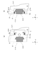
本発明を適用したセグメント1は、図2に示すように、本体部2と、セグメント継手3と、抜け出し防止装置4とを備える。 As shown in FIG. 2, the segment 1 to which the present invention is applied includes a main body portion 2, a segment joint 3, and a slip-out prevention device 4.

本体部2は、周方向Wに延在し、周方向Wと交わり軸方向Xに延在する一対の端面21と、軸方向Xと交わり周方向Wに延在する一対の側面22と、法線方向Y(トンネル法線方向)と交わり軸方向X及び周方向Wと平行な面を有する一対の面20とで構成される6面を備える。本体部2は、例えば軸方向Xの幅が200mm~2,500mm程度であり、トンネルの法線方向Yの厚さが150mm~700mm程度である。 The main body 2 has a pair of end faces 21 extending in the circumferential direction W, intersecting the circumferential direction W and extending in the axial direction X, and a pair of side surfaces 22 extending in the circumferential direction W intersecting the axial direction X. It has six planes composed of a pair of planes 20 having planes intersecting the linear direction Y (tunnel normal direction) and having planes parallel to the axial direction X and the circumferential direction W. The main body portion 2 has, for example, a width of about 200 mm to 2,500 mm in the axial direction X and a thickness of about 150 mm to 700 mm in the normal direction Y of the tunnel.

セグメント継手3は、端面21に配置されるほか、例えば側面22に配置されてもよい。即ち、セグメント継手3は、例えば端面21、並びに切羽側C及び坑口側Dの側面22の少なくとも何れかに配置される。セグメント継手3は、一対のセグメント1a、1bを周方向Wに沿って連結するために用いられる。セグメント継手3は、雄側連結部31及び雌側連結部32の少なくとも何れかを有する。なお、一対のセグメント1a、1bがボルトとナットで連結される場合は、ボルトが雄側連結部31、ナットが雌側連結部32となる。 The segment joint 3 may be arranged on the end surface 21 or, for example, the side surface 22. That is, the segment joint 3 is arranged, for example, on at least one of the end surface 21 and the side surface 22 of the face side C and the wellhead side D. The segment joint 3 is used to connect a pair of segments 1a and 1b along the circumferential direction W. The segment joint 3 has at least one of a male side connecting portion 31 and a female side connecting portion 32. When the pair of segments 1a and 1b are connected by a bolt and a nut, the bolt becomes the male side connecting portion 31 and the nut becomes the female side connecting portion 32.

雄側連結部31及び雌側連結部32は、周方向Wに沿って本体部2を連結する。雄側連結部31及び雌側連結部32は、一方を他方に挿入することで、周方向Wに隣接する一方のセグメント1aの端面21と、他方のセグメント1bの端面21とを当接させ、一方のセグメント1aの本体部2と、他方のセグメント1bの本体部2とを連結するためのものである。例えば、一方のセグメント1aに設けられた雌側連結部32に、他方のセグメント1bに設けられた雄側連結部31を軸方向Xに挿入し嵌合させることで(図2の一点鎖線矢印)、一対のセグメント1a、1bを連結させることができる。 The male side connecting portion 31 and the female side connecting portion 32 connect the main body portion 2 along the circumferential direction W. By inserting one of the male-side connecting portion 31 and the female-side connecting portion 32 into the other, the end surface 21 of one segment 1a adjacent to the circumferential direction W and the end surface 21 of the other segment 1b are brought into contact with each other. This is for connecting the main body 2 of one segment 1a and the main body 2 of the other segment 1b. For example, by inserting and fitting the male side connecting portion 31 provided in the other segment 1b into the female side connecting portion 32 provided in one segment 1a in the axial direction X (one-dot chain arrow in FIG. 2). , A pair of segments 1a and 1b can be connected.

例えば、セグメント1の一方の端面21に雄側連結部31が設けられ、他方の端面21に雌側連結部32が設けられるほか、両方の端面21に雄側連結部31のみ、又は雌側連結部32のみが設けられてもよい。なお、雄側連結部31及び雌側連結部32の設けられる数は任意である。 For example, one end face 21 of the segment 1 is provided with a male side connecting portion 31, the other end face 21 is provided with a female side connecting portion 32, and both end faces 21 are provided with only the male side connecting portion 31 or the female side connecting portion. Only the portion 32 may be provided. The number of the male side connecting portion 31 and the female side connecting portion 32 is arbitrary.

雄側連結部31は、雌側連結部32と嵌合する一端を有する。雄側連結部31は、例えば一端が本体部2から突出し、他端が本体部2に埋設される。一端は、例えば他端よりも厚く、軸方向Xに延びる柱状又は円柱状である。 The male side connecting portion 31 has one end that fits with the female side connecting portion 32. For example, one end of the male side connecting portion 31 protrudes from the main body portion 2, and the other end is embedded in the main body portion 2. One end is, for example, a columnar or columnar shape that is thicker than the other end and extends in the axial direction X.

雌側連結部32は、雄側連結部31の一端と嵌合する形状を有する。雌側連結部32は、例えば本体部2に埋設され、本体部2に形成され雄側連結部31の一端が挿入できる溝部23に連接する。この場合、雄側連結部31は、溝部23を介して雌側連結部32と嵌合される。なお、溝部23は、図2に示すように、軸方向Xに沿って延在するほか、例えば法線方向Yに沿って延在してもよい。雌側連結部32は、例えば軸方向Xに延在する筒状であり、軸方向Xに延在するスリットを有する。 The female side connecting portion 32 has a shape that fits with one end of the male side connecting portion 31. The female side connecting portion 32 is embedded in the main body portion 2, for example, and is connected to a groove portion 23 formed in the main body portion 2 and into which one end of the male side connecting portion 31 can be inserted. In this case, the male side connecting portion 31 is fitted with the female side connecting portion 32 via the groove portion 23. As shown in FIG. 2, the groove portion 23 may extend along the axial direction X or may extend along the normal direction Y, for example. The female side connecting portion 32 has, for example, a cylindrical shape extending in the axial direction X and has a slit extending in the axial direction X.

抜け出し防止装置4は、側面22に設けられる。抜け出し防止装置4は、連結された一対のセグメント1a、1bのセグメント継手3の抜け出しを防止するために用いられる。抜け出し防止装置4は、雄側抑止部41及び雌側抑止部42の少なくとも何れかを有する。 The slip-out prevention device 4 is provided on the side surface 22. The slip-out prevention device 4 is used to prevent the segment joints 3 of the pair of connected segments 1a and 1b from slipping out. The escape prevention device 4 has at least one of the male side deterrence unit 41 and the female side deterrence unit 42.

なお、図14に示すように、抜け出し防止装置4は、例えば少なくとも軸方向Xにおける切羽側Cの側面22に設けられる。抜け出し防止装置4が切羽側Cの側面22にのみ設けられる場合、セグメント1が抜け出そうとする際において、図15に示すように、セグメント1の継手に設ける組立用の微小な隙間に伴うセグメント1の回転が、セグメント1の本体の坑口側D端部を回転中心として発生する。これは、坑口側Dには組立済みのセグメント1が既に配置されており、切羽側C端部を回転中心として坑口側D端部が開く方向の回転は、これらのセグメント1により拘束されるためである。 As shown in FIG. 14, the slip-out prevention device 4 is provided, for example, on the side surface 22 of the face side C at least in the axial direction X. When the slip-out prevention device 4 is provided only on the side surface 22 of the face side C, when the segment 1 is about to slip out, as shown in FIG. 15, the segment 1 due to the minute gap for assembly provided in the joint of the segment 1 is provided. Rotation occurs with the D end on the wellhead side of the main body of the segment 1 as the center of rotation. This is because the assembled segment 1 is already arranged on the wellhead side D, and the rotation in the direction in which the wellhead side D end is opened with the face side C end as the rotation center is constrained by these segments 1. Is.

このとき、図16に示すように、抜け出し防止装置4の雄側抑止部41と雌側抑止部42とが競ることで抜け出しをより強固に抑止するが、競りによる抜け出し防止力Fは競りによる反力Pの余弦成分となる(F=P×cosφ)。この回転角φは、図16(a)に示すように、回転角φ=tan-1(a/B)(aは、雄側抑止部41と雌側抑止部42とが競るまでの隙間を示し、Bは、セグメント1の幅を示す)で算出される。即ち回転角φは、セグメント幅Bに反比例するものである。このことから、図16(b)に示すように、セグメント幅Bが小さいほど回転角φは大きくなるため、競りによる抜け出し防止力F1は小さくなる。これに対し、図16(c)に示すように、セグメント幅Bが大きいほど回転角φは小さくなることから、競りによる抜け出し防止力F2は大きくなる。 At this time, as shown in FIG. 16, the male side deterrence unit 41 and the female side deterrence unit 42 of the escape prevention device 4 compete with each other to more firmly suppress the escape, but the escape prevention force F due to the auction is the anti-slip due to the auction. It is a cosine component of the power factor (F = P × cosφ). As shown in FIG. 16A, the angle of rotation φ is such that the angle of rotation φ = tan -1 (a / B) (a is a gap until the male side restraint portion 41 and the female side restraint portion 42 compete with each other. Shown, B is calculated by (indicating the width of segment 1). That is, the angle of rotation φ is inversely proportional to the segment width B. From this, as shown in FIG. 16B, the smaller the segment width B, the larger the rotation angle φ, and therefore the smaller the pull-out prevention force F1 due to the auction. On the other hand, as shown in FIG. 16C, the larger the segment width B, the smaller the rotation angle φ, and therefore the larger the pull-out prevention force F2 due to the auction.

図17は、セグメント幅Bを横軸に示し、縦軸に一般的なセグメント幅Bの上限である2,500mmのときの競りによる抜け出し防止力Fを100%としたときの各セグメント幅Bにおける競りによる抜け出し防止力Fの比率を示したものである。図17に示すように、セグメント幅Bが250mm未満になると競りによる抜け出し防止力Fが大きく減少するため、競りによる抜け出し防止効果を発揮し、工事の安全性をより確実に確保するためには、セグメント幅Bは250mm以上2,500mm以下とすることで本発明の効果が大きく発揮される。 In FIG. 17, the segment width B is shown on the horizontal axis, and the vertical axis is the each segment width B when the auction prevention force F at 2,500 mm, which is the upper limit of the general segment width B, is set to 100%. It shows the ratio of the escape prevention force F by the auction. As shown in FIG. 17, when the segment width B is less than 250 mm, the pull-out prevention force F due to the auction is greatly reduced. The effect of the present invention is greatly exhibited by setting the segment width B to 250 mm or more and 2,500 mm or less.

雄側抑止部41及び雌側抑止部42は、切羽側C及び坑口側Dの少なくとも何れかの側面22に、セグメント継手3を挿入する向きに対して反対の向きに、雄側連結部31が雌側連結部32から抜け出すことを防止するためのものである。ここで、「挿入する向き」とは、軸方向X又は法線方向Yにおいて、一方のセグメント1aに他方のセグメント1bを連結するときにおける挿入直前の位置から挿入直後までの向きを示す。例えば図2の場合、他方のセグメント1bが一点鎖線矢印の示す向きに挿入されるため、「挿入する向き」は、軸方向Xにおける切羽側Cから坑口側Dを示す。このとき、「挿入する向きに対して反対の向き」は、軸方向Xにおける坑口側Dから切羽側Cを示す。このため、雄側抑止部41及び雌側抑止部42は、本体部2における坑口側Dから切羽側Cの向きにおける抜け出しを抑止する。なお、例えば「挿入する向き」は、法線方向Yにおける内空側Iから地山側Aを示してもよい。このとき、「挿入する向きに対して反対の向き」は、法線方向Yにおける地山側Aから内空側Iを示す。この場合、雄側抑止部41及び雌側抑止部42は、本体部2における地山側Aから内空側Iの向きにおける抜け出しを抑止する。 In the male-side restraint portion 41 and the female-side restraint portion 42, the male-side connecting portion 31 is placed on at least one of the side surfaces 22 of the face side C and the wellhead side D in the direction opposite to the direction in which the segment joint 3 is inserted. This is to prevent the female side connecting portion 32 from coming off. Here, the "insertion direction" indicates the direction from the position immediately before insertion to immediately after insertion when the other segment 1b is connected to one segment 1a in the axial direction X or the normal direction Y. For example, in the case of FIG. 2, since the other segment 1b is inserted in the direction indicated by the alternate long and short dash arrow, the “insertion direction” indicates the wellhead side D from the face side C in the axial direction X. At this time, the "direction opposite to the insertion direction" indicates the wellhead side D to the face side C in the axial direction X. Therefore, the male deterrent section 41 and the female deterrent section 42 prevent the main body portion 2 from coming out in the direction from the wellhead side D to the face side C. For example, the "insertion direction" may indicate the ground side A from the inner sky side I in the normal direction Y. At this time, the "direction opposite to the insertion direction" indicates the ground side A to the inner sky side I in the normal direction Y. In this case, the male side deterrent unit 41 and the female side deterrence unit 42 prevent the main body unit 2 from coming out in the direction from the ground side A to the inner air side I.

例えば、一方のセグメント1aに設けられた雌側抑止部42に、他方のセグメント1bに設けられた雄側抑止部41を係合させることで、セグメント1bの本体部2の挿入向きに対して反対の向きにおける抜け出しを抑止することができる。特に、抜け出し防止装置4を側面22に配置することで、セグメント1の回転等を強固に抑制することができる。 For example, by engaging the female deterrent portion 42 provided in one segment 1a with the male deterrent portion 41 provided in the other segment 1b, the insertion direction of the main body portion 2 of the segment 1b is opposite. It is possible to prevent the escape in the direction of. In particular, by arranging the slip-out prevention device 4 on the side surface 22, the rotation of the segment 1 and the like can be strongly suppressed.

例えば、セグメント1の一方の側面22において、周方向Wの一端部に雄側抑止部41が設けられ、他端部に雌側抑止部42が設けられるほか、両端部に雄側抑止部41のみ、又は雌側抑止部42のみが設けられてもよい。雄側抑止部41及び雌側抑止部42の設けられる数は任意である。 For example, on one side surface 22 of the segment 1, a male deterrent portion 41 is provided at one end in the circumferential direction W, a female deterrent portion 42 is provided at the other end, and only the male deterrent portion 41 is provided at both ends. , Or only the female deterrent portion 42 may be provided. The number of the male deterrent unit 41 and the female deterrence unit 42 is arbitrary.

雄側抑止部41は、雌側抑止部42と係合する端部41aを有する。雄側抑止部41は、例えば端部41aが本体部2から突出し、他端が本体部2に埋設される。雄側抑止部41は、例えばL字状又はT字状に形成されてもよい。なお、図2に示すように、端部41aが周方向Wに沿って突出する場合、他端が側面22に埋設されるため、雄側抑止部41は側面22に設けられる。また、雄側抑止部41の他端が側面22に埋設されず、側面22と同一平面上に設けられて周方向Wに突出する場合においても、雄側抑止部41は側面22に設けられる。 The male deterrent portion 41 has an end portion 41a that engages with the female deterrent portion 42. For example, the male side restraining portion 41 has an end portion 41a protruding from the main body portion 2 and the other end embedded in the main body portion 2. The male deterrent portion 41 may be formed in an L-shape or a T-shape, for example. As shown in FIG. 2, when the end portion 41a projects along the circumferential direction W, the other end is embedded in the side surface 22, so that the male side restraint portion 41 is provided on the side surface 22. Further, even when the other end of the male deterrent portion 41 is not embedded in the side surface 22 and is provided on the same plane as the side surface 22 and protrudes in the circumferential direction W, the male deterrent portion 41 is provided on the side surface 22.

雌側抑止部42は、雄側抑止部41と係合する支持部42aを有する。雌側抑止部42は、例えば側面22に形成された溝状であり、溝内に支持部42aが設けられる。雌側抑止部42は、例えば図2のように、周方向Wに沿って側面22から端面21まで延在する溝状でもよい。 The female deterrent portion 42 has a support portion 42a that engages with the male deterrent portion 41. The female side restraint portion 42 has, for example, a groove shape formed on the side surface 22, and a support portion 42a is provided in the groove. The female side restraining portion 42 may have a groove shape extending from the side surface 22 to the end surface 21 along the circumferential direction W, for example, as shown in FIG.

本発明を適用したセグメント1には、例えば図3に示すように、少なくとも一対の端面21及び一対の側面22に鋼材5が配置されてもよい。 In the segment 1 to which the present invention is applied, the steel material 5 may be arranged on at least a pair of end faces 21 and a pair of side surfaces 22 as shown in FIG. 3, for example.

鋼材5は、本体部2に設けられた雄側連結部31及び雌側連結部32の周辺を切り欠いた状態で設けられるほか、例えば雄側連結部31及び雌側連結部32の少なくとも何れかが、溶接接合等により鋼材5に固定されてもよい。 The steel material 5 is provided in a state where the periphery of the male side connecting portion 31 and the female side connecting portion 32 provided in the main body portion 2 is cut out, and for example, at least one of the male side connecting portion 31 and the female side connecting portion 32. However, it may be fixed to the steel material 5 by welding or the like.

鋼材5は、本体部2に設けられた雄側抑止部41及び雌側抑止部42の周辺を切り欠いた状態で設けられるほか、例えば雄側抑止部41及び雌側抑止部42の少なくとも何れかが、溶接接合等により鋼材5に固定されてもよい。 The steel material 5 is provided in a state where the periphery of the male deterrent portion 41 and the female deterrent portion 42 provided in the main body portion 2 is cut out, and for example, at least one of the male deterrence portion 41 and the female deterrent portion 42. However, it may be fixed to the steel material 5 by welding or the like.

鋼材5は、例えば図4に示すように、フランジ5fを有してもよい。フランジ5fは、例えば側面22に配置される鋼材5における法線方向Yの両端部に形成され、軸方向Xに延在する。 The steel material 5 may have a flange 5f, for example, as shown in FIG. The flanges 5f are formed at both ends of the steel material 5 arranged on the side surface 22 in the normal direction Y and extend in the axial direction X, for example.

本発明を適用したセグメント1は、例えば側面22に配置されたリング継手8を備える。リング継手8は、一対のセグメント1を軸方向Xに沿って連結するために用いられる。 The segment 1 to which the present invention is applied includes, for example, a ring joint 8 arranged on the side surface 22. The ring joint 8 is used to connect the pair of segments 1 along the axial direction X.

リング継手8は、雄側継手81と、雌側継手82とを有する。雄側継手81及び雌側継手82は、互いに嵌合する形状を有する。例えば、坑口側Dのセグメント1(セグメントリング71)の側面22に設けられた雌側継手82に、切羽側Cのセグメント1の側面22に設けられた雄側継手81を嵌合させることで、軸方向Xに沿った一対のセグメント1を連結させることができる。 The ring joint 8 has a male side joint 81 and a female side joint 82. The male side joint 81 and the female side joint 82 have a shape that fits each other. For example, by fitting the male side joint 81 provided on the side surface 22 of the segment 1 on the face side C to the female side joint 82 provided on the side surface 22 of the segment 1 (segment ring 71) on the wellhead side D. A pair of segments 1 along the axial direction X can be connected.

雄側継手81は、一端が本体部2から突出し、他端が本体部2に埋設されるほか、例えば他端が溶接接合等により鋼材5に固定されてもよい。雌側継手82は、本体部2に埋設されるほか、例えば溶接接合等により鋼材5に固定されてもよい。 One end of the male side joint 81 protrudes from the main body portion 2, the other end is embedded in the main body portion 2, and the other end may be fixed to the steel material 5 by, for example, welding. The female side joint 82 may be embedded in the main body 2 or may be fixed to the steel material 5 by, for example, welding.

本発明を適用したセグメント1として、上述したセグメント1a、1b(Aピース)のほか、例えば図5に示すように、キーセグメント1k、及びキーセグメント1kと連結されるセグメント1c、1d(Bピース、Cピース)が用いられてもよい。 As the segment 1 to which the present invention is applied, in addition to the above-mentioned segments 1a and 1b (A piece), for example, as shown in FIG. 5, the key segment 1k and the segments 1c and 1d (B piece, which are connected to the key segment 1k). C piece) may be used.

セグメント1a、1bの両端面21は、軸方向Xに沿って略平行に形成される。これに対し、キーセグメント1kは、軸方向Xに沿ってテーパー状に形成され、キーセグメント1kの両端面21が、軸方向Xに沿って傾斜を有する。また、セグメント1c、1dにおいて、セグメント1a、1bと連結される一方の端面21は、軸方向Xに沿って略平行に形成され、キーセグメント1kと連結される他方の端面21は、軸方向Xに沿って傾斜を有する。 Both end faces 21 of the segments 1a and 1b are formed substantially in parallel along the axial direction X. On the other hand, the key segment 1k is formed in a tapered shape along the axial direction X, and both end faces 21 of the key segment 1k have an inclination along the axial direction X. Further, in the segments 1c and 1d, one end face 21 connected to the segments 1a and 1b is formed substantially in parallel along the axial direction X, and the other end face 21 connected to the key segment 1k is formed in the axial direction X. Has a slope along.

抜け出し防止装置4は、例えば少なくともキーセグメント1kに配置される。キーセグメント1kの両端面21は、軸方向Xに沿って傾斜している。すなわち、キーセグメント1kは、セグメント1c、1dと連結したあとに、トンネルに土水圧が作用することで発生するトンネル周方向軸力が、キーセグメント1kの軸方向Xに沿って傾斜した端面21において、キーセグメント1kの抜け出し方向となる軸方向Xの分力を生み出すことになり、特に大きな抜け出し力が作用することで滑動し、抜け出す可能性が高い。このため、キーセグメント1kの側面22に抜け出し防止装置4を配置することで、キーセグメント1kの本体部2の挿入向きに対して反対の向きにおける抜け出しを抑止することができる。 The slip-out prevention device 4 is arranged, for example, in at least the key segment 1k. Both end faces 21 of the key segment 1k are inclined along the axial direction X. That is, the key segment 1k is connected to the segments 1c and 1d, and then the tunnel circumferential axial force generated by the action of soil water pressure on the tunnel is inclined along the axial direction X of the key segment 1k at the end surface 21. , A component force in the axial direction X, which is the exit direction of the key segment 1k, is generated, and there is a high possibility that the key segment 1k will slide and exit due to the action of a particularly large exit force. Therefore, by arranging the slip-out prevention device 4 on the side surface 22 of the key segment 1k, it is possible to prevent the key segment 1k from slipping out in the direction opposite to the insertion direction of the main body portion 2.

図18は、キーセグメント1kに作用するトンネル周方向軸力で無次元化した抜け出し力Pと、キーセグメント1kの端面21の傾斜角度θとの関係を表したものである。なお、この関係は、くさびの計算式を用いて導かれ、抜け出し力Pは、トンネル周方向軸力N、傾斜角度θ及び端面21の摩擦係数μにより求められる。シールド工事用標準セグメント(平成13年7月 社団法人日本下水道協会)によれば、一般的な鋼材と鋼材間の摩擦係数は0.3、コンクリートとコンクリート間の摩擦係数は0.5とされており、摩擦係数が十分に大きい場合は、傾斜角度θが小さい領域では抜け出し力Pよりも摩擦力Fが大きいため、抜け出しは発生しない。しかし、通常、キーセグメント1kの組立時においては、端面21には潤滑剤が塗布され、摩擦係数μが通常の1/10程度になることも報告されている。その場合、図18に示すように、キーセグメント1kの傾斜角度θが2度以上の範囲では抜け出し力Pが発生し得る。そのため、特に傾斜角度θが2度以上に設定されるキーセグメント1kに対して抜け出し防止装置4を配置することで、工事の安全性を確実に確保することができる。なお、図5では、キーセグメント1kの側面22に雄側抑止部41が設けられているが、雌側抑止部42が設けられてもよい。 FIG. 18 shows the relationship between the exit force P, which is made dimensionless by the tunnel circumferential axial force acting on the key segment 1k, and the inclination angle θ of the end face 21 of the key segment 1k. This relationship is derived using a wedge calculation formula, and the escape force P is obtained from the tunnel circumferential axial force N, the inclination angle θ, and the friction coefficient μ of the end face 21. According to the standard segment for shield construction (July 2001, Japan Sewerage Association), the coefficient of friction between general steel materials is 0.3, and the coefficient of friction between concretes is 0.5. When the friction coefficient is sufficiently large, the friction force F is larger than the pull-out force P in the region where the inclination angle θ is small, so that the pull-out does not occur. However, it has also been reported that, normally, when the key segment 1k is assembled, a lubricant is applied to the end face 21 and the friction coefficient μ becomes about 1/10 of the usual one. In that case, as shown in FIG. 18, a breakout force P may be generated in the range where the inclination angle θ of the key segment 1k is 2 degrees or more. Therefore, in particular, by arranging the escape prevention device 4 for the key segment 1k in which the inclination angle θ is set to 2 degrees or more, the safety of the construction can be surely ensured. In FIG. 5, the male side deterrent unit 41 is provided on the side surface 22 of the key segment 1k, but the female side deterrence unit 42 may be provided.

<抜け出し防止装置4の一例>
抜け出し防止装置4は、例えば図6(a)の矢印に示すように、溝状の雌側抑止部42内に雄側抑止部41を移動させることにより、一対のセグメント1a、1bの抜け出しを防止する。なお、図6(a)では、セグメント1bを軸方向Xに沿って移動させる例を示すが、例えばセグメント1bを法線方向Yに沿って移動させるようにしてもよい。
<Example of slip-out prevention device 4>
The escape prevention device 4 prevents the pair of segments 1a and 1b from coming out by moving the male side restraint portion 41 into the groove-shaped female side restraint portion 42, for example, as shown by the arrow in FIG. 6A. do. Although FIG. 6A shows an example in which the segment 1b is moved along the axial direction X, for example, the segment 1b may be moved along the normal direction Y.

雄側抑止部41の端部41aは、例えば法線方向Yの両側に拡幅された部分を有する。端部41aとして、例えば雄側抑止部41と一体に形成された鋼材等が用いられる。 The end portion 41a of the male side restraining portion 41 has, for example, widened portions on both sides in the normal direction Y. As the end portion 41a, for example, a steel material integrally formed with the male side restraining portion 41 is used.

雌側抑止部42の支持部42aは、例えば溝状の雌側抑止部42における法線方向Yの側面に少なくとも1つ(図6では2つ)設けられる。支持部42aとして、例えばバネ等の弾性体に固定された鋼材等が用いられる。 At least one support portion 42a of the female side restraint portion 42 is provided on the side surface of the groove-shaped female side restraint portion 42 in the normal direction Y (two in FIG. 6). As the support portion 42a, for example, a steel material fixed to an elastic body such as a spring is used.

例えば図6(a)の矢印方向(挿入向き)にセグメント1bを移動させた場合、図6(b)に示すように、端部41aは支持部42aと係合する。これにより、セグメント1bの各本体部2の挿入向きに対して反対の向きにおける抜け出しを抑止することができる。 For example, when the segment 1b is moved in the direction of the arrow (insertion direction) in FIG. 6A, the end portion 41a engages with the support portion 42a as shown in FIG. 6B. As a result, it is possible to prevent the segment 1b from coming out in the direction opposite to the insertion direction of each main body portion 2.

例えば端部41aにおける法線方向Yの高さにおいて、先端側の高さh1は、基端側(側面22側)の高さh2よりも小さい。また、雌側抑止部42における法線方向Yの両側面に設けられた一対の支持部42aの間の距離において、側面22側の高さh3は、底面側の高さh4よりも大きい。この場合、例えば高さh1が高さh3よりも小さく形成されることで、雄側抑止部41を雌側抑止部42に挿入し易くなり、セグメント1bの移動を円滑に行うことができる。また、例えば高さh2が高さh4よりも大きく形成されることで、雄側抑止部41を雌側抑止部42と係合させ易くなり、セグメント1bの本体部2の挿入向きに対して反対の向きにおける抜け出しを容易に抑止することができる。 For example, at the height of the end portion 41a in the normal direction Y, the height h1 on the tip end side is smaller than the height h2 on the base end side (side surface 22 side). Further, in the distance between the pair of support portions 42a provided on both side surfaces in the normal direction Y of the female side restraint portion 42, the height h3 on the side surface 22 side is larger than the height h4 on the bottom surface side. In this case, for example, when the height h1 is formed smaller than the height h3, the male side restraining portion 41 can be easily inserted into the female side restraining portion 42, and the segment 1b can be smoothly moved. Further, for example, when the height h2 is formed larger than the height h4, it becomes easy to engage the male deterrent portion 41 with the female deterrent portion 42, which is opposite to the insertion direction of the main body portion 2 of the segment 1b. It is possible to easily prevent the escape in the direction of.

端部41aは、例えば周方向Wから見て、基端側から先端側に沿って端部の高さが減少するテーパー状に形成される。また、支持部42aは、例えば周方向Wから見て、底面側から側面22側に沿って支持部42aの間隔が拡大するテーパー状に形成される。これにより、セグメント1bの移動をより円滑に行うことができるとともに、セグメント1bの本体部2の挿入向きに対して反対の向きにおける抜け出しを容易に抑止することができる。 The end portion 41a is formed in a tapered shape in which the height of the end portion decreases from the base end side to the tip end side, for example, when viewed from the circumferential direction W. Further, the support portion 42a is formed in a tapered shape in which the distance between the support portions 42a increases from the bottom surface side to the side surface 22 side, for example, when viewed from the circumferential direction W. As a result, the segment 1b can be moved more smoothly, and the segment 1b can be easily prevented from coming out in the direction opposite to the insertion direction of the main body portion 2.

<抜け出し防止装置4の第1変形例>
次に、抜け出し防止装置4の第1変形例について説明する。上述した抜け出し防止装置4と、第1変形例との違いは、雄側抑止部41と雌側抑止部42との係合する位置が異なる点である。なお、上述した内容と同様の構成については、説明を省略する。
<First modification of the slip-out prevention device 4>
Next, a first modification of the slip-out prevention device 4 will be described. The difference between the above-mentioned escape prevention device 4 and the first modification is that the engaging positions of the male side restraint unit 41 and the female side restraint unit 42 are different. The description of the same configuration as described above will be omitted.

雄側抑止部41は、例えば図7に示すように、端部41aの代わりに端面41bを、雌側抑止部42と係合(接着及び粘着を含む)させてもよい。この場合、雌側抑止部42は、例えば底面に設けられた支持部42bにより、端面41bを係合させる。支持部42bとして、例えば接着性若しくは粘着性を有する粘弾性体、又は、マジックテープ(登録商標)等の面状に着脱可能な面ファスナーが用いられる。 As shown in FIG. 7, for example, the male deterrent portion 41 may engage (including adhesion and adhesion) the end surface 41b with the female deterrent portion 42 instead of the end portion 41a. In this case, the female side restraining portion 42 engages the end surface 41b with, for example, a support portion 42b provided on the bottom surface. As the support portion 42b, for example, a viscoelastic body having adhesiveness or adhesiveness, or a surface fastener such as magic tape (registered trademark) that can be attached and detached in a surface shape is used.

例えば図7(b)の矢印方向(挿入向き)にセグメント1bを移動させた場合、図7(c)に示すように、端面41bは支持部42bと係合する。これにより、セグメント1bの本体部2の挿入向きに対して反対の向きにおける抜け出しを抑止することができる。 For example, when the segment 1b is moved in the direction of the arrow (insertion direction) in FIG. 7 (b), the end face 41b engages with the support portion 42b as shown in FIG. 7 (c). As a result, it is possible to prevent the segment 1b from coming out in the direction opposite to the insertion direction of the main body portion 2.

なお、例えば支持部42bとして一対の脱着部を有する面ファスナーが用いられる場合、例えば支持部42bの一方の脱着部を予め端面41bと係合させた状態で、溝状の雌側抑止部42内に雄側抑止部41を移動させてもよい。この場合においても、雌側抑止部42の底面に他方の脱着部を設けることで、一対の脱着部が当接して固定され、セグメント1bの本体部2の挿入向きに対して反対の向きにおける抜け出しを抑止することができる。 For example, when a hook-and-loop fastener having a pair of detachable portions is used as the support portion 42b, for example, in a state where one of the detachable portions of the support portion 42b is previously engaged with the end surface 41b, the inside of the groove-shaped female side restraining portion 42. The male deterrent unit 41 may be moved to. Also in this case, by providing the other detachable portion on the bottom surface of the female side restraining portion 42, the pair of detachable portions are abutted and fixed, and the segment 1b comes out in the direction opposite to the insertion direction of the main body portion 2. Can be deterred.

抜け出し防止装置4は、例えば図8に示すように、法線方向Yに沿ってセグメント継手3と近接して配置されてもよい。すなわち、セグメント継手3は、側面22に配置される。この場合、一対のセグメント1a、1bを連結するとき、セグメント継手3の嵌合状態を作業者等が容易に目視確認できる。また、一対のセグメント1a、1bを連結するとき、セグメント継手3の雄側連結部31が、連結先のセグメント1aに接触して損傷を受ける可能性を極めて低くすることができる。 The slip-out prevention device 4 may be arranged in close proximity to the segment joint 3 along the normal direction Y, for example, as shown in FIG. That is, the segment joint 3 is arranged on the side surface 22. In this case, when the pair of segments 1a and 1b are connected, the fitted state of the segment joint 3 can be easily visually confirmed by an operator or the like. Further, when the pair of segments 1a and 1b are connected, the possibility that the male side connecting portion 31 of the segment joint 3 comes into contact with the connected segment 1a and is damaged can be extremely reduced.

抜け出し防止装置4は、例えば図9に示すように、セグメント継手3と一体に形成されてもよい。雄側抑止部41の端面41bは、雄側連結部31における軸方向Xの坑口側Dの面に設けられる。雌側抑止部42の支持部42bは、溝状に形成された雌側連結部32の底面に設けられる。 The slip-out prevention device 4 may be integrally formed with the segment joint 3, for example, as shown in FIG. The end surface 41b of the male side restraining portion 41 is provided on the surface of the male side connecting portion 31 on the wellhead side D in the axial direction X. The support portion 42b of the female side restraining portion 42 is provided on the bottom surface of the female side connecting portion 32 formed in a groove shape.

例えば図9(b)の矢印方向(挿入向き)にセグメント1bを移動させた場合、図9(c)に示すように、雄側連結部31は雌側連結部32と嵌合するとともに、端面41bは支持部42bと係合する。これにより、セグメント1bの本体部2の挿入向きに対して反対の向きにおける抜け出しを抑止することができる。また、セグメント継手3と抜け出し防止装置4とが別体に形成される場合に比べて、雄側連結部31と雌側連結部32との嵌合、及び、雄側抑止部41と雌側抑止部42との係合を容易に実施することができる。これにより、一対のセグメント1a、1bの連結に費やす時間を削減することが可能となる。 For example, when the segment 1b is moved in the direction of the arrow (insertion direction) in FIG. 9 (b), the male side connecting portion 31 is fitted with the female side connecting portion 32 and the end face is as shown in FIG. 9 (c). 41b engages with the support 42b. As a result, it is possible to prevent the segment 1b from coming out in the direction opposite to the insertion direction of the main body portion 2. Further, as compared with the case where the segment joint 3 and the slip-out prevention device 4 are formed separately, the male side connecting portion 31 and the female side connecting portion 32 are fitted together, and the male side restraining portion 41 and the female side restraining portion are suppressed. Engagement with the portion 42 can be easily carried out. This makes it possible to reduce the time spent connecting the pair of segments 1a and 1b.

<抜け出し防止装置4の第2変形例>
次に、抜け出し防止装置4の第2変形例について説明する。上述した抜け出し防止装置4と、第2変形例との違いは、雌側抑止部42を有しない点である。このとき、抜け出し防止装置4は、側面22に配置される鋼材5又は鋼製のセグメント継手3に固定される。なお、上述した内容と同様の構成については、説明を省略する。
<Second modification of the slip-out prevention device 4>
Next, a second modification of the slip-out prevention device 4 will be described. The difference between the above-mentioned escape prevention device 4 and the second modification is that it does not have the female side restraining unit 42. At this time, the slip-out prevention device 4 is fixed to the steel material 5 or the steel segment joint 3 arranged on the side surface 22. The description of the same configuration as described above will be omitted.

抜け出し防止装置4は、例えば図10に示すように、雄側抑止部41のみを有してもよい。雄側抑止部41は、セグメント1aの側面22に配置される鋼材5上に設けられる。雄側抑止部41は、例えば鋼材5に固定されたねじ付きスタッド等の軸部材に取り付けられた抑止部材41cを有する。抑止部材41cとして、例えば鋼板等が用いられる。抑止部材41cは、例えば軸部材に螺合され、軸方向Xを軸として回転させることができる。 The escape prevention device 4 may have only the male deterrent unit 41, for example, as shown in FIG. The male deterrent portion 41 is provided on the steel material 5 arranged on the side surface 22 of the segment 1a. The male deterrent portion 41 has a deterrent member 41c attached to a shaft member such as a threaded stud fixed to a steel material 5, for example. As the restraining member 41c, for example, a steel plate or the like is used. The restraining member 41c is screwed into, for example, a shaft member, and can be rotated about the axial direction X as an axis.

抑止部材41cは、例えば図10(a)の矢印に示す方向に回転し、突出部32aと一体に設けられた接合部32bからなる雌側連結部32の突出部32aが抑止部材41cと鋼材5との間に挟まれる。これにより、雄側抑止部41は、雌側連結部32と係合する。 The restraining member 41c rotates, for example, in the direction indicated by the arrow in FIG. 10A, and the protruding portion 32a of the female side connecting portion 32 including the joint portion 32b provided integrally with the protruding portion 32a has the restraining member 41c and the steel material 5. It is sandwiched between and. As a result, the male deterrent portion 41 engages with the female side connecting portion 32.

接合部32bは、雄側抑止部41が設けられたセグメント1aと連結されるセグメント1b側に設けられ、セグメント1bの側面22に配置される鋼材5に固定される。雌側連結部32は、周方向Wに沿って接合部32bから突出部32aまで延在する。 The joint portion 32b is provided on the segment 1b side connected to the segment 1a provided with the male side restraint portion 41, and is fixed to the steel material 5 arranged on the side surface 22 of the segment 1b. The female side connecting portion 32 extends from the joining portion 32b to the protruding portion 32a along the circumferential direction W.

雄側連結部31は、雄側抑止部41が設けられたセグメント1a側に設けられ、セグメント1aの側面22に配置される鋼材5に固定され、軸方向Xに突出する。例えば図10(b)の軸方向Xにおける上方から下方の向き(挿入向き)にセグメント1bを移動させた場合、雄側連結部31は、雌側連結部32の突出部32a側の軸方向Xに形成された孔32hと嵌合する。これにより、一対のセグメント1a、1bが連結される。 The male-side connecting portion 31 is provided on the segment 1a side where the male-side restraining portion 41 is provided, is fixed to the steel material 5 arranged on the side surface 22 of the segment 1a, and projects in the axial direction X. For example, when the segment 1b is moved from the upper side to the lower side (insertion direction) in the axial direction X in FIG. 10B, the male side connecting portion 31 has the axial direction X on the protruding portion 32a side of the female side connecting portion 32. Fits with the hole 32h formed in. As a result, the pair of segments 1a and 1b are connected.

この場合においても、雄側抑止部41は、雌側連結部32と係合することで、セグメント1bの本体部2の挿入向きに対して反対の向きにおける抜け出しを抑止することができる。また、雌側抑止部42を形成する必要が無いため、セグメント1の製造工程数を減少させることが可能となる。 Even in this case, the male-side deterrent portion 41 can be engaged with the female-side connecting portion 32 to prevent the segment 1b from coming out in the direction opposite to the insertion direction of the main body portion 2. Further, since it is not necessary to form the female side restraining portion 42, it is possible to reduce the number of manufacturing steps of the segment 1.

<抜け出し防止装置4の第3変形例>
次に、抜け出し防止装置4の第3変形例について説明する。上述した抜け出し防止装置4の第2変形例と、第3変形例との違いは、雄側抑止部41が一対のセグメント1a、1bを連結したあとに設けられる点である。なお、上述した内容と同様の構成については、説明を省略する。
<Third modification example of the slip-out prevention device 4>
Next, a third modification of the slip-out prevention device 4 will be described. The difference between the second modification and the third modification of the above-mentioned escape prevention device 4 is that the male side restraining unit 41 is provided after connecting the pair of segments 1a and 1b. The description of the same configuration as described above will be omitted.

抜け出し防止装置4は、例えば図11に示すように、一対のセグメント1a、1bを連結したあとに配置され、雄側抑止部41のみを有してもよい。雄側抑止部41は、突出部材41dを有し、突出部材41dとして鋼材等が用いられる。突出部材41dは、例えば図11(d)に示すように、平板の主面と直角方向(図11(d)では軸方向X)に突出する挿通部41e及び当接部41fを有する。挿通部41eは、例えば一対の当接部41fの間に設けられる円柱状部材で、挿通部41e及び当接部41fは平板部材である。 As shown in FIG. 11, for example, the slip-out prevention device 4 may be arranged after connecting the pair of segments 1a and 1b, and may have only the male side restraining unit 41. The male side restraining portion 41 has a protruding member 41d, and a steel material or the like is used as the protruding member 41d. As shown in FIG. 11D, for example, the projecting member 41d has an insertion portion 41e and an abutting portion 41f projecting in a direction perpendicular to the main surface of the flat plate (axial direction X in FIG. 11D). The insertion portion 41e is, for example, a columnar member provided between a pair of contact portions 41f, and the insertion portion 41e and the contact portion 41f are flat plate members.

例えば図11(b)の軸方向Xにおける上方から下方の向き(挿入向き)にセグメント1bを移動させた場合、雄側連結部31と、雌側連結部32に形成された孔32hとが嵌合する。これにより、一対のセグメント1a、1bが連結される。この状態で、図11(c)、図11(d)に示すように、挿通部41eが、雄側連結部31の軸方向Xに形成された孔31hに挿通される。このとき、雌側連結部32の突出部32aは、当接部41fと鋼材5との間に挟まれる。これにより、雄側抑止部41は、雌側連結部32と係合する。 For example, when the segment 1b is moved from the upper side to the lower side (insertion direction) in the axial direction X in FIG. 11B, the male side connecting portion 31 and the hole 32h formed in the female side connecting portion 32 are fitted. It fits. As a result, the pair of segments 1a and 1b are connected. In this state, as shown in FIGS. 11 (c) and 11 (d), the insertion portion 41e is inserted into the hole 31h formed in the axial direction X of the male side connecting portion 31. At this time, the protruding portion 32a of the female side connecting portion 32 is sandwiched between the contact portion 41f and the steel material 5. As a result, the male deterrent portion 41 engages with the female side connecting portion 32.

この場合においても、雄側抑止部41は、雌側連結部32と係合することで、セグメント1bの本体部2の挿入向きに対して反対の向きにおける抜け出しを抑止することができる。また、雌側抑止部42を形成する必要が無いため、セグメント1の製造工程数を減少させることが可能となる。 Even in this case, the male-side deterrent portion 41 can be engaged with the female-side connecting portion 32 to prevent the segment 1b from coming out in the direction opposite to the insertion direction of the main body portion 2. Further, since it is not necessary to form the female side restraining portion 42, it is possible to reduce the number of manufacturing steps of the segment 1.

<抜け出し防止装置4の第4変形例>
次に、抜け出し防止装置4の第4変形例について説明する。上述した抜け出し防止装置4と、第4変形例との違いは、抜け出し防止装置4が報知部6に近接して設けられる点である。なお、上述した内容と同様の構成については、説明を省略する。
<Fourth modification of the slip-out prevention device 4>
Next, a fourth modification of the slip-out prevention device 4 will be described. The difference between the above-mentioned escape prevention device 4 and the fourth modification is that the escape prevention device 4 is provided close to the notification unit 6. The description of the same configuration as described above will be omitted.

抜け出し防止装置4は、例えば図12に示すように、抜け出し防止装置4の係合状態を判定し、作業者等に報知する報知部6に近接して設けられる。報知部6は、例えば雌側抑止部42内に設けられる。 As shown in FIG. 12, for example, the slip-out prevention device 4 is provided close to the notification unit 6 that determines the engaged state of the slip-out prevention device 4 and notifies the operator or the like. The notification unit 6 is provided in, for example, the female side restraint unit 42.

報知部6は、例えばセンサ部と、制御部と、出力部とを有する。センサ部は、抜け出し防止装置4の係合状態を信号化する。センサ部として、例えば図13に示す接触式センサのほか、電磁波を利用した非接触式センサ等が用いられる。制御部は、センサ部からの信号に基づいて抜け出し防止装置4の係合状態を判定する。出力部は、判定結果を作業者等に報知する。出力部は、例えば無線通信等を介して判定結果を送信し、作業者等の通信端末に判定結果を報知するほか、例えば電気的に接続されたLED等を点灯させ、作業者等に報知してもよい。 The notification unit 6 has, for example, a sensor unit, a control unit, and an output unit. The sensor unit signals the engagement state of the disconnection prevention device 4. As the sensor unit, for example, in addition to the contact type sensor shown in FIG. 13, a non-contact type sensor using an electromagnetic wave or the like is used. The control unit determines the engagement state of the escape prevention device 4 based on the signal from the sensor unit. The output unit notifies the operator and the like of the determination result. The output unit transmits the determination result via, for example, wireless communication and notifies the communication terminal of the operator or the like of the determination result, and also turns on, for example, an electrically connected LED or the like to notify the operator or the like. You may.

報知部6は、例えば図13(a)に示すように、雌側抑止部42の支持部42aと接して設けられてもよい。例えば図13(a)の矢印方向(挿入向き)にセグメント1bを移動させた場合、図13(b)に示すように、報知部6は、雄側抑止部41と雌側抑止部42とに挟まれる。これにより、報知部6は、雄側抑止部41と雌側抑止部42とが係合したと判定し、作業者等に報知する。 As shown in FIG. 13A, for example, the notification unit 6 may be provided in contact with the support unit 42a of the female side restraint unit 42. For example, when the segment 1b is moved in the direction of the arrow (insertion direction) in FIG. 13A, as shown in FIG. Sandwiched. As a result, the notification unit 6 determines that the male-side deterrence unit 41 and the female-side deterrence unit 42 are engaged, and notifies the operator or the like.

本発明を適用したセグメント1によれば、抜け出し防止装置4は、本体部2の側面22に設けられ、セグメント継手3を挿入する向きに対して反対の向きに雄側連結部31が雌側連結部32から抜け出すことを抑止するための雄側抑止部41及び雌側抑止部42の少なくとも一方を備える。このため、抜け出し力によってセグメント1の回転等が発生した場合においても、抜け出し防止装置4が端面21に設けられた場合に比べて回転に抵抗する偶力間の距離を長くとることが可能となり、セグメント1の回転等を強固に抑制することができる。これは、セグメント1の組立にはセグメント1の継手に微小な隙間を設ける必要があるため、セグメント1が抜け出そうとする際には、片側が目開きすることになり、セグメント1が回転する形で抜け出すことになる。その隙間が最も大きくなる側面22に抜け出し防止装置4を設けることによって、競りによる抜け出し抑止効果が大きく現れる。これにより、セグメント1の抜け出しを確実に防止することが可能となり、工事の安全性の向上を実現することができる。 According to the segment 1 to which the present invention is applied, the slip-out prevention device 4 is provided on the side surface 22 of the main body portion 2, and the male side connecting portion 31 is connected to the female side in the direction opposite to the direction in which the segment joint 3 is inserted. It includes at least one of a male deterrence unit 41 and a female deterrence unit 42 for deterring the unit from coming out of the unit 32. Therefore, even when the segment 1 is rotated due to the pull-out force, it is possible to take a longer distance between the couples that resist the rotation as compared with the case where the pull-out prevention device 4 is provided on the end face 21. The rotation of the segment 1 can be strongly suppressed. This is because it is necessary to provide a minute gap in the joint of the segment 1 for assembling the segment 1, so that when the segment 1 tries to come out, one side is opened and the segment 1 rotates. Will get out of. By providing the slip-out prevention device 4 on the side surface 22 where the gap is the largest, the slip-out prevention effect by auction is greatly exhibited. As a result, it is possible to reliably prevent the segment 1 from coming off, and it is possible to improve the safety of construction work.

また、本発明を適用したセグメント1によれば、抜け出し防止装置4は、本体部2の側面22に設けられる。本体部2の端面21に抜け出し防止装置4を設ける場合では、連結作業の間、一対のセグメント1の端面21同士の距離が小さく損傷するおそれがある。それに対して、抜け出し防止装置4を側面22に設けることにより、一対のセグメント1を連結するとき、連結する端面21から抜け出し防止装置4を離しておくことができるので、連結先のセグメント1に接触して損傷を受ける可能性を極めて低くすることができる。これにより、一対のセグメント1が連結した後、抜け出し防止装置4を確実に作動させることが可能となり、工事の安全性を向上させることが可能となる。 Further, according to the segment 1 to which the present invention is applied, the slip-out prevention device 4 is provided on the side surface 22 of the main body 2. When the slip-out prevention device 4 is provided on the end face 21 of the main body 2, the distance between the end faces 21 of the pair of segments 1 may be small and damaged during the connecting operation. On the other hand, by providing the escape prevention device 4 on the side surface 22, when connecting the pair of segments 1, the escape prevention device 4 can be separated from the end surface 21 to be connected, so that the segment 1 is in contact with the connection destination. The possibility of damage can be extremely reduced. As a result, after the pair of segments 1 are connected, the slip-out prevention device 4 can be reliably operated, and the safety of construction can be improved.

また、本発明を適用したセグメント1によれば、本体部2の備える6面のうち、少なくとも一対の端面21及び一対の側面22に、鋼材5が配置される。このため、本体部2に作用する抜け出し防止装置4の反力に対し、鋼材5の拘束効果によるコンクリートの補強効果が得られ、より強固にセグメント1の抜け出しを防止することができる。これにより、工事の安全性をさらに向上させることが可能となる。また、一対のセグメント1を連結するとき、本体部2が連結先の抜け出し防止装置4に接触して損傷を受けることを防ぐことができる。これにより、セグメント1の耐久性を向上させることが可能となる。 Further, according to the segment 1 to which the present invention is applied, the steel material 5 is arranged on at least a pair of end faces 21 and a pair of side surfaces 22 among the six faces provided in the main body 2. Therefore, the concrete is reinforced by the restraining effect of the steel material 5 against the reaction force of the slip-out prevention device 4 acting on the main body 2, and the slip-out of the segment 1 can be prevented more firmly. This makes it possible to further improve the safety of construction work. Further, when the pair of segments 1 are connected, it is possible to prevent the main body 2 from coming into contact with the disconnection prevention device 4 at the connection destination and being damaged. This makes it possible to improve the durability of the segment 1.

また、本発明を適用したセグメント1によれば、抜け出し防止装置4は、側面22に配置される鋼材5又は鋼製のセグメント継手3に固定される。このため、抜け出し防止装置4の反力が鋼材5に作用し、より強固にセグメント1の抜け出しを防止することができる。これにより、工事の安全性をさらに向上させることが可能となる。 Further, according to the segment 1 to which the present invention is applied, the slip-out prevention device 4 is fixed to the steel material 5 or the steel segment joint 3 arranged on the side surface 22. Therefore, the reaction force of the escape prevention device 4 acts on the steel material 5, and the escape of the segment 1 can be prevented more firmly. This makes it possible to further improve the safety of construction work.

また、本発明を適用したセグメント1によれば、抜け出し防止装置4は、少なくとも軸方向Xにおける切羽側Cの側面22に設けられる。このため、一対のセグメント1を連結するとき、切羽側Cのセグメントリング71の側面22は未だ組み立てていない隣のセグメントリング71が無いため、抜け出し防止装置4の係合状態を作業者等が容易に目視確認できる。また、一対のセグメント1を連結するとき、切羽側Cの抜け出し防止装置4は連結先のセグメント1の端面21に近接することがないため、抜け出し防止装置4が連結先のセグメント1に接触して損傷を受ける可能性をさらに低下することができ、一対のセグメント1が連結した後、抜け出し防止装置4を確実に作動させることが可能となる。これにより、工事の安全性をさらに向上させることが可能となる。 Further, according to the segment 1 to which the present invention is applied, the slip-out prevention device 4 is provided on the side surface 22 of the face side C at least in the axial direction X. Therefore, when connecting the pair of segments 1, the side surface 22 of the segment ring 71 on the face side C does not have an adjacent segment ring 71 that has not been assembled yet, so that the operator or the like can easily check the engaged state of the slip-out prevention device 4. Can be visually confirmed. Further, when the pair of segments 1 are connected, the escape prevention device 4 on the face side C does not come close to the end surface 21 of the connection destination segment 1, so that the escape prevention device 4 comes into contact with the connection destination segment 1. The possibility of being damaged can be further reduced, and after the pair of segments 1 are connected, the escape prevention device 4 can be reliably operated. This makes it possible to further improve the safety of construction work.

また、本発明を適用したセグメント1によれば、セグメント継手3は、切羽側C及び坑口側Dの側面22に配置される。このため、一対のセグメント1を連結するとき、セグメント継手3の嵌合状態を作業者等が容易に目視確認できる。これにより、工事の安全性をさらに向上させることが可能となる。また、一対のセグメント1を連結するとき、セグメント継手3が連結先のセグメント1に接触して損傷を受ける可能性を極めて低くすることができる。これにより、セグメント継手3の耐久性を向上させることが可能となる。 Further, according to the segment 1 to which the present invention is applied, the segment joint 3 is arranged on the side surface 22 of the face side C and the wellhead side D. Therefore, when connecting the pair of segments 1, the operator or the like can easily visually confirm the fitted state of the segment joint 3. This makes it possible to further improve the safety of construction work. Further, when the pair of segments 1 are connected, the possibility that the segment joint 3 comes into contact with the connected segment 1 and is damaged can be extremely reduced. This makes it possible to improve the durability of the segment joint 3.

また、本発明を適用したセグメント1によれば、特に第4変形例における抜け出し防止装置4は、報知部6に近接して設けられる。このため、一対のセグメント1を連結するとき、セグメント1から離れた場所に待機する作業者等が、抜け出し防止装置4の係合状態を容易に確認できる。これにより、工事の安全性をさらに向上させることが可能となる。 Further, according to the segment 1 to which the present invention is applied, the escape prevention device 4 particularly in the fourth modification is provided in the vicinity of the notification unit 6. Therefore, when connecting the pair of segments 1, an operator or the like who stands by at a place away from the segments 1 can easily confirm the engaged state of the escape prevention device 4. This makes it possible to further improve the safety of construction work.

また、本発明を適用したセグメント1によれば、抜け出し防止装置4は、少なくともキーセグメント1kに設けられる。キーセグメント1kでは、トンネルに土水圧が作用することで発生するトンネル周方向軸力が、キーセグメント1kの軸方向Xに傾斜した端面21において、キーセグメント1kの抜け出し方向となるトンネル軸方向分力を生み出すことになり、特に大きな抜け出し力が発生しやすい。一方、抜け出し防止装置4が軸方向Xに傾斜したテーパー状の端面21に設けられた場合に比べて、抜け出し防止装置4の反力が直角かつ単純に本体部2へ作用する。これらにより、より大きな抜け出し力に対してより強固にセグメント1の抜け出しを防止することが可能となり、工事の安全性を大きく向上させることが可能となる。また、キーセグメント1kの挿入時には、キーセグメント1kの両端面21が連結先のセグメント1に極めて近接するため、抜け出し防止装置4が端面21に設けられた場合に比べて、抜け出し防止装置4が連結先のセグメント1に接触して損傷を受ける可能性を飛躍的に低くすることが可能となり、工事の安全性を大きく向上させることが可能となる。また、例えば抜け出し防止装置4をキーセグメント1kのみに設けることで、工事の安全性を向上させたうえで、材料費の削減が可能となる。 Further, according to the segment 1 to which the present invention is applied, the escape prevention device 4 is provided at least in the key segment 1k. In the key segment 1k, the tunnel circumferential axial force generated by the action of soil water pressure on the tunnel is the tunnel axial component force in the exit direction of the key segment 1k at the end face 21 inclined in the axial direction X of the key segment 1k. Will be produced, and a particularly large pull-out force is likely to occur. On the other hand, as compared with the case where the withdrawal prevention device 4 is provided on the tapered end surface 21 inclined in the axial direction X, the reaction force of the withdrawal prevention device 4 acts on the main body 2 at a right angle and simply. As a result, it is possible to prevent the segment 1 from coming out more firmly against a larger pull-out force, and it is possible to greatly improve the safety of construction work. Further, when the key segment 1k is inserted, both end faces 21 of the key segment 1k are extremely close to the segment 1 of the connection destination, so that the escape prevention device 4 is connected as compared with the case where the escape prevention device 4 is provided on the end surface 21. It is possible to dramatically reduce the possibility of damage due to contact with the previous segment 1, and it is possible to greatly improve the safety of construction work. Further, for example, by providing the escape prevention device 4 only in the key segment 1k, it is possible to improve the safety of construction work and reduce the material cost.

以上、本発明の実施形態の例について詳細に説明したが、上述した実施形態は、何れも本発明を実施するにあたっての具体化の例を示したものに過ぎず、これらによって本発明の技術的範囲が限定的に解釈されてはならない。 Although the examples of the embodiments of the present invention have been described in detail above, all of the above-described embodiments are merely examples of specific examples in carrying out the present invention, and the technical aspects of the present invention are thereby used. The scope should not be construed in a limited way.

1 :セグメント
1a :セグメント
1b :セグメント
1c :セグメント
1d :セグメント
1k :キーセグメント
2 :本体部
20 :面
21 :端面
22 :側面
23 :溝部
3 :セグメント継手
31 :雄側連結部
31h :孔
32 :雌側連結部
32a :突出部
32b :接合部
32h :孔
4 :抜け出し防止装置
41 :雄側抑止部
41a :端部
41b :端面
41c :抑止部材
41d :突出部材
41e :挿通部
41f :当接部
42 :雌側抑止部
42a :支持部
42b :支持部
5 :鋼材
5f :フランジ
6 :報知部
7 :シールドトンネル
70 :シールドマシン
71 :セグメントリング
8 :リング継手
81 :雄側継手
82 :雌側継手
9 :地中
A :地山側
I :内空側
C :切羽側
D :坑口側
S :内側空間
W :周方向
X :軸方向
Y :法線方向
1: Segment 1a: Segment 1b: Segment 1c: Segment 1d: Segment 1k: Key segment 2: Main body 20: Surface 21: End surface 22: Side surface 23: Groove 3: Segment joint 31: Male side connecting portion 31h: Hole 32: Female side connecting part 32a: Protruding part 32b: Joint part 32h: Hole 4: Breakout prevention device 41: Male side restraining part 41a: End part 41b: End face 41c: Suppressing member 41d: Protruding member 41e: Insertion part 41f: Contact part 42: Female side restraint part 42a: Support part 42b: Support part 5: Steel material 5f: Flange 6: Notification part 7: Shield tunnel 70: Shield machine 71: Segment ring 8: Ring joint 81: Male side joint 82: Female side joint 9: Underground A: Ground side I: Inner air side C: Face side D: Wellhead side S: Inner space W: Circumferential direction X: Axial direction Y: Normal direction

Claims (7)

トンネルの周方向及び軸方向に対して相互に連結することで前記トンネルを構築するためのセグメントであって、
前記セグメントは、
トンネル周方向の一対の端面と、トンネル軸方向の一対の側面と、トンネル法線方向の一対の面とで構成される6面を備える本体部と、
前記端面、並びに前記トンネル軸方向の切羽側及び坑口側の前記側面の少なくとも何れかに配置されたセグメント継手と
を備え、
前記セグメント継手は、一方を他方に挿入することで前記トンネル周方向に隣接する他のセグメントの端面と前記端面とを当接させ、前記本体部と前記他のセグメントの本体部とを連結するための雄側連結部及び雌側連結部の少なくとも何れかを有し、
前記トンネル軸方向の切羽側及び坑口側の少なくとも何れかの前記側面に、前記セグメント継手を挿入する向きに対して反対の向きに前記雄側連結部が前記雌側連結部から抜け出すことを抑止するための雄側抑止部及び雌側抑止部の少なくとも一方を備える抜け出し防止装置が設けられること
を特徴とするセグメント。
A segment for constructing the tunnel by connecting them to each other in the circumferential direction and the axial direction of the tunnel.
The segment is
A main body having six faces composed of a pair of end faces in the tunnel circumferential direction, a pair of side surfaces in the tunnel axial direction, and a pair of faces in the tunnel normal direction.
The end face and the segment joints arranged on at least one of the side surfaces on the face side and the wellhead side in the direction of the tunnel axis are provided.
In order to connect the main body portion and the main body portion of the other segment, the segment joint abuts the end face of the other segment adjacent to the tunnel circumferential direction by inserting one into the other. Has at least one of the male and female joints of the
Prevents the male side connecting portion from coming out of the female side connecting portion on at least one of the side surfaces of the face side and the wellhead side in the tunnel axial direction in a direction opposite to the direction in which the segment joint is inserted. A segment characterized by being provided with a slip-out prevention device provided with at least one of a male deterrent and a female deterrent.
前記6面のうち、少なくとも一対の前記端面、及び一対の前記側面に、鋼材が配置されること
を特徴とする請求項1記載のセグメント。
The segment according to claim 1, wherein steel materials are arranged on at least a pair of the end faces and a pair of the side surfaces among the six faces.
前記抜け出し防止装置は、前記側面に配置される前記鋼材又は鋼製の前記セグメント継手に固定されること
を特徴とする請求項2記載のセグメント。
The segment according to claim 2, wherein the slip-out prevention device is fixed to the steel material or the segment joint made of steel arranged on the side surface.
前記抜け出し防止装置は、前記側面のうち、少なくとも前記トンネル軸方向の切羽側の前記側面に設けられること
を特徴とする請求項1~3の何れか1項記載のセグメント。
The segment according to any one of claims 1 to 3, wherein the slip-out prevention device is provided on at least the side surface of the side surface on the face side in the tunnel axial direction.
前記セグメント継手は、前記トンネル軸方向の切羽側及び坑口側の前記側面に配置されること
を特徴とする請求項1~4の何れか1項記載のセグメント。
The segment according to any one of claims 1 to 4, wherein the segment joint is arranged on the side surface on the face side and the wellhead side in the tunnel axial direction.
前記抜け出し防止装置は、前記抜け出し防止装置の係合状態を報知する報知部に近接して設けられること
を特徴とする請求項1~5の何れか1項記載のセグメント。
The segment according to any one of claims 1 to 5, wherein the slip-out prevention device is provided close to a notification unit that notifies the engagement state of the slip-out prevention device.
前記抜け出し防止装置は、少なくともキーセグメントに設けられること
を特徴とする請求項1~6の何れか1項記載のセグメント。
The segment according to any one of claims 1 to 6, wherein the slip-out prevention device is provided at least in a key segment.
JP2018100509A 2018-05-25 2018-05-25 segment Active JP7006507B2 (en)

Priority Applications (1)

Application Number Priority Date Filing Date Title
JP2018100509A JP7006507B2 (en) 2018-05-25 2018-05-25 segment

Applications Claiming Priority (1)

Application Number Priority Date Filing Date Title
JP2018100509A JP7006507B2 (en) 2018-05-25 2018-05-25 segment

Publications (2)

Publication Number Publication Date
JP2019203352A JP2019203352A (en) 2019-11-28
JP7006507B2 true JP7006507B2 (en) 2022-01-24

Family

ID=68726398

Family Applications (1)

Application Number Title Priority Date Filing Date
JP2018100509A Active JP7006507B2 (en) 2018-05-25 2018-05-25 segment

Country Status (1)

Country Link
JP (1) JP7006507B2 (en)

Families Citing this family (1)

* Cited by examiner, † Cited by third party
Publication number Priority date Publication date Assignee Title
CN115030223B (en) * 2022-06-02 2024-02-06 温州大学 Positioning and butt-joint device for underwater suspension tunnel pipe body

Citations (3)

* Cited by examiner, † Cited by third party
Publication number Priority date Publication date Assignee Title
JP2002502001A (en) 1998-01-29 2002-01-22 シー.ヴィ.ブキャン リミテッド Equipment for joining concrete members
JP2015140540A (en) 2014-01-28 2015-08-03 日本ヒューム株式会社 Joint part structure of segment
JP2015196999A (en) 2014-04-02 2015-11-09 大成建設株式会社 Joint structure of segment

Family Cites Families (3)

* Cited by examiner, † Cited by third party
Publication number Priority date Publication date Assignee Title
US4497590A (en) * 1982-03-08 1985-02-05 Crs Group, Inc. Tunnel lining
JPH11229785A (en) * 1998-02-16 1999-08-24 Sumitomo Metal Ind Ltd Joint structure for segment
JPH11315698A (en) * 1998-03-04 1999-11-16 Nippon Steel Corp Steel shell segment

Patent Citations (3)

* Cited by examiner, † Cited by third party
Publication number Priority date Publication date Assignee Title
JP2002502001A (en) 1998-01-29 2002-01-22 シー.ヴィ.ブキャン リミテッド Equipment for joining concrete members
JP2015140540A (en) 2014-01-28 2015-08-03 日本ヒューム株式会社 Joint part structure of segment
JP2015196999A (en) 2014-04-02 2015-11-09 大成建設株式会社 Joint structure of segment

Also Published As

Publication number Publication date
JP2019203352A (en) 2019-11-28

Similar Documents

Publication Publication Date Title
JP7006507B2 (en) segment
AU2014358146B2 (en) Joint structure for steel pipe pile
JP7104641B2 (en) Synthetic segments, rings and buried structures
US20190226204A1 (en) Composite Building Panel and Shell
AU2016316135A1 (en) Vertical joint structure of hat-type steel sheet piling, vertically joined hat-type steel sheet piling unit, and steel wall
JP7091833B2 (en) segment
JP6405631B2 (en) Steel pipe pile rotation deterrent structure
JP5559123B2 (en) Beam support rotating piece
JP6355391B2 (en) Segment joint structure
JP5538244B2 (en) Steel pipe connection structure
US20040163853A1 (en) Friction support means with mechanical advantage
JP5155614B2 (en) Tunnel segment connection structure
JP2019203354A (en) segment
US20170299095A1 (en) Pipe joint
JP6477335B2 (en) Steel pipe pile joint rotation deterrent structure
JP2013174103A (en) Hat-shaped steel sheet pile and structure using the same
JP7373640B2 (en) Segment piece and segment ring
JP2554197B2 (en) Tunnel segment and protective member for tunnel segment
KR102252425B1 (en) Active grooved joint and the pipe joint method using the same
JP5737058B2 (en) H-shaped sheet pile
JP4532952B2 (en) Anchor spacer
JP6905813B2 (en) Synthetic segment and ring
JP3516802B2 (en) Segment joint structure
JP4364530B2 (en) Segment mis-suppression device
JP5639927B2 (en) Fitting that connects segment rings

Legal Events

Date Code Title Description
A621 Written request for application examination

Free format text: JAPANESE INTERMEDIATE CODE: A621

Effective date: 20210112

A977 Report on retrieval

Free format text: JAPANESE INTERMEDIATE CODE: A971007

Effective date: 20211126

TRDD Decision of grant or rejection written
A01 Written decision to grant a patent or to grant a registration (utility model)

Free format text: JAPANESE INTERMEDIATE CODE: A01

Effective date: 20211207

A61 First payment of annual fees (during grant procedure)

Free format text: JAPANESE INTERMEDIATE CODE: A61

Effective date: 20211220