JP7004391B6 - Aerosol generator with rotating heater - Google Patents
Aerosol generator with rotating heater Download PDFInfo
- Publication number
- JP7004391B6 JP7004391B6 JP2019555168A JP2019555168A JP7004391B6 JP 7004391 B6 JP7004391 B6 JP 7004391B6 JP 2019555168 A JP2019555168 A JP 2019555168A JP 2019555168 A JP2019555168 A JP 2019555168A JP 7004391 B6 JP7004391 B6 JP 7004391B6
- Authority
- JP
- Japan
- Prior art keywords
- heater
- cigarette
- holder
- rotating
- cradle
- Prior art date
- Legal status (The legal status is an assumption and is not a legal conclusion. Google has not performed a legal analysis and makes no representation as to the accuracy of the status listed.)
- Active
Links
Images


Classifications
-
- A—HUMAN NECESSITIES
- A24—TOBACCO; CIGARS; CIGARETTES; SIMULATED SMOKING DEVICES; SMOKERS' REQUISITES
- A24F—SMOKERS' REQUISITES; MATCH BOXES; SIMULATED SMOKING DEVICES
- A24F40/00—Electrically operated smoking devices; Component parts thereof; Manufacture thereof; Maintenance or testing thereof; Charging means specially adapted therefor
- A24F40/40—Constructional details, e.g. connection of cartridges and battery parts
- A24F40/46—Shape or structure of electric heating means
-
- A—HUMAN NECESSITIES
- A24—TOBACCO; CIGARS; CIGARETTES; SIMULATED SMOKING DEVICES; SMOKERS' REQUISITES
- A24F—SMOKERS' REQUISITES; MATCH BOXES; SIMULATED SMOKING DEVICES
- A24F40/00—Electrically operated smoking devices; Component parts thereof; Manufacture thereof; Maintenance or testing thereof; Charging means specially adapted therefor
- A24F40/50—Control or monitoring
-
- A—HUMAN NECESSITIES
- A24—TOBACCO; CIGARS; CIGARETTES; SIMULATED SMOKING DEVICES; SMOKERS' REQUISITES
- A24B—MANUFACTURE OR PREPARATION OF TOBACCO FOR SMOKING OR CHEWING; TOBACCO; SNUFF
- A24B15/00—Chemical features or treatment of tobacco; Tobacco substitutes, e.g. in liquid form
- A24B15/10—Chemical features of tobacco products or tobacco substitutes
- A24B15/16—Chemical features of tobacco products or tobacco substitutes of tobacco substitutes
-
- A—HUMAN NECESSITIES
- A24—TOBACCO; CIGARS; CIGARETTES; SIMULATED SMOKING DEVICES; SMOKERS' REQUISITES
- A24F—SMOKERS' REQUISITES; MATCH BOXES; SIMULATED SMOKING DEVICES
- A24F40/00—Electrically operated smoking devices; Component parts thereof; Manufacture thereof; Maintenance or testing thereof; Charging means specially adapted therefor
- A24F40/40—Constructional details, e.g. connection of cartridges and battery parts
- A24F40/48—Fluid transfer means, e.g. pumps
-
- A—HUMAN NECESSITIES
- A24—TOBACCO; CIGARS; CIGARETTES; SIMULATED SMOKING DEVICES; SMOKERS' REQUISITES
- A24F—SMOKERS' REQUISITES; MATCH BOXES; SIMULATED SMOKING DEVICES
- A24F40/00—Electrically operated smoking devices; Component parts thereof; Manufacture thereof; Maintenance or testing thereof; Charging means specially adapted therefor
- A24F40/50—Control or monitoring
- A24F40/51—Arrangement of sensors
-
- A—HUMAN NECESSITIES
- A24—TOBACCO; CIGARS; CIGARETTES; SIMULATED SMOKING DEVICES; SMOKERS' REQUISITES
- A24F—SMOKERS' REQUISITES; MATCH BOXES; SIMULATED SMOKING DEVICES
- A24F40/00—Electrically operated smoking devices; Component parts thereof; Manufacture thereof; Maintenance or testing thereof; Charging means specially adapted therefor
- A24F40/50—Control or monitoring
- A24F40/53—Monitoring, e.g. fault detection
-
- A—HUMAN NECESSITIES
- A24—TOBACCO; CIGARS; CIGARETTES; SIMULATED SMOKING DEVICES; SMOKERS' REQUISITES
- A24F—SMOKERS' REQUISITES; MATCH BOXES; SIMULATED SMOKING DEVICES
- A24F40/00—Electrically operated smoking devices; Component parts thereof; Manufacture thereof; Maintenance or testing thereof; Charging means specially adapted therefor
- A24F40/50—Control or monitoring
- A24F40/57—Temperature control
-
- A—HUMAN NECESSITIES
- A24—TOBACCO; CIGARS; CIGARETTES; SIMULATED SMOKING DEVICES; SMOKERS' REQUISITES
- A24F—SMOKERS' REQUISITES; MATCH BOXES; SIMULATED SMOKING DEVICES
- A24F40/00—Electrically operated smoking devices; Component parts thereof; Manufacture thereof; Maintenance or testing thereof; Charging means specially adapted therefor
- A24F40/60—Devices with integrated user interfaces
-
- A—HUMAN NECESSITIES
- A24—TOBACCO; CIGARS; CIGARETTES; SIMULATED SMOKING DEVICES; SMOKERS' REQUISITES
- A24F—SMOKERS' REQUISITES; MATCH BOXES; SIMULATED SMOKING DEVICES
- A24F40/00—Electrically operated smoking devices; Component parts thereof; Manufacture thereof; Maintenance or testing thereof; Charging means specially adapted therefor
- A24F40/85—Maintenance, e.g. cleaning
-
- A—HUMAN NECESSITIES
- A24—TOBACCO; CIGARS; CIGARETTES; SIMULATED SMOKING DEVICES; SMOKERS' REQUISITES
- A24F—SMOKERS' REQUISITES; MATCH BOXES; SIMULATED SMOKING DEVICES
- A24F40/00—Electrically operated smoking devices; Component parts thereof; Manufacture thereof; Maintenance or testing thereof; Charging means specially adapted therefor
- A24F40/90—Arrangements or methods specially adapted for charging batteries thereof
- A24F40/95—Arrangements or methods specially adapted for charging batteries thereof structurally associated with cases
-
- A—HUMAN NECESSITIES
- A46—BRUSHWARE
- A46B—BRUSHES
- A46B15/00—Other brushes; Brushes with additional arrangements
- A46B15/0055—Brushes combined with other articles normally separate from the brushing process, e.g. combs, razors, mirrors
-
- A—HUMAN NECESSITIES
- A46—BRUSHWARE
- A46B—BRUSHES
- A46B15/00—Other brushes; Brushes with additional arrangements
- A46B15/0097—Self supporting, e.g. brushes that stand upright or in other particular ways
-
- A—HUMAN NECESSITIES
- A61—MEDICAL OR VETERINARY SCIENCE; HYGIENE
- A61M—DEVICES FOR INTRODUCING MEDIA INTO, OR ONTO, THE BODY; DEVICES FOR TRANSDUCING BODY MEDIA OR FOR TAKING MEDIA FROM THE BODY; DEVICES FOR PRODUCING OR ENDING SLEEP OR STUPOR
- A61M15/00—Inhalators
- A61M15/06—Inhaling appliances shaped like cigars, cigarettes or pipes
-
- H—ELECTRICITY
- H02—GENERATION; CONVERSION OR DISTRIBUTION OF ELECTRIC POWER
- H02J—CIRCUIT ARRANGEMENTS OR SYSTEMS FOR SUPPLYING OR DISTRIBUTING ELECTRIC POWER; SYSTEMS FOR STORING ELECTRIC ENERGY
- H02J7/00—Circuit arrangements for charging or depolarising batteries or for supplying loads from batteries
- H02J7/0042—Circuit arrangements for charging or depolarising batteries or for supplying loads from batteries characterised by the mechanical construction
- H02J7/0044—Circuit arrangements for charging or depolarising batteries or for supplying loads from batteries characterised by the mechanical construction specially adapted for holding portable devices containing batteries
-
- H—ELECTRICITY
- H05—ELECTRIC TECHNIQUES NOT OTHERWISE PROVIDED FOR
- H05B—ELECTRIC HEATING; ELECTRIC LIGHT SOURCES NOT OTHERWISE PROVIDED FOR; CIRCUIT ARRANGEMENTS FOR ELECTRIC LIGHT SOURCES, IN GENERAL
- H05B3/00—Ohmic-resistance heating
- H05B3/02—Details
- H05B3/03—Electrodes
-
- H—ELECTRICITY
- H05—ELECTRIC TECHNIQUES NOT OTHERWISE PROVIDED FOR
- H05B—ELECTRIC HEATING; ELECTRIC LIGHT SOURCES NOT OTHERWISE PROVIDED FOR; CIRCUIT ARRANGEMENTS FOR ELECTRIC LIGHT SOURCES, IN GENERAL
- H05B3/00—Ohmic-resistance heating
- H05B3/02—Details
- H05B3/06—Heater elements structurally combined with coupling elements or holders
-
- H—ELECTRICITY
- H05—ELECTRIC TECHNIQUES NOT OTHERWISE PROVIDED FOR
- H05B—ELECTRIC HEATING; ELECTRIC LIGHT SOURCES NOT OTHERWISE PROVIDED FOR; CIRCUIT ARRANGEMENTS FOR ELECTRIC LIGHT SOURCES, IN GENERAL
- H05B3/00—Ohmic-resistance heating
- H05B3/40—Heating elements having the shape of rods or tubes
- H05B3/42—Heating elements having the shape of rods or tubes non-flexible
-
- A—HUMAN NECESSITIES
- A24—TOBACCO; CIGARS; CIGARETTES; SIMULATED SMOKING DEVICES; SMOKERS' REQUISITES
- A24D—CIGARS; CIGARETTES; TOBACCO SMOKE FILTERS; MOUTHPIECES FOR CIGARS OR CIGARETTES; MANUFACTURE OF TOBACCO SMOKE FILTERS OR MOUTHPIECES
- A24D1/00—Cigars; Cigarettes
- A24D1/20—Cigarettes specially adapted for simulated smoking devices
-
- A—HUMAN NECESSITIES
- A24—TOBACCO; CIGARS; CIGARETTES; SIMULATED SMOKING DEVICES; SMOKERS' REQUISITES
- A24F—SMOKERS' REQUISITES; MATCH BOXES; SIMULATED SMOKING DEVICES
- A24F40/00—Electrically operated smoking devices; Component parts thereof; Manufacture thereof; Maintenance or testing thereof; Charging means specially adapted therefor
- A24F40/10—Devices using liquid inhalable precursors
-
- A—HUMAN NECESSITIES
- A24—TOBACCO; CIGARS; CIGARETTES; SIMULATED SMOKING DEVICES; SMOKERS' REQUISITES
- A24F—SMOKERS' REQUISITES; MATCH BOXES; SIMULATED SMOKING DEVICES
- A24F40/00—Electrically operated smoking devices; Component parts thereof; Manufacture thereof; Maintenance or testing thereof; Charging means specially adapted therefor
- A24F40/20—Devices using solid inhalable precursors
-
- A—HUMAN NECESSITIES
- A46—BRUSHWARE
- A46B—BRUSHES
- A46B2200/00—Brushes characterized by their functions, uses or applications
- A46B2200/30—Brushes for cleaning or polishing
- A46B2200/3013—Brushes for cleaning the inside or the outside of tubes
-
- H—ELECTRICITY
- H02—GENERATION; CONVERSION OR DISTRIBUTION OF ELECTRIC POWER
- H02J—CIRCUIT ARRANGEMENTS OR SYSTEMS FOR SUPPLYING OR DISTRIBUTING ELECTRIC POWER; SYSTEMS FOR STORING ELECTRIC ENERGY
- H02J7/00—Circuit arrangements for charging or depolarising batteries or for supplying loads from batteries
- H02J7/0042—Circuit arrangements for charging or depolarising batteries or for supplying loads from batteries characterised by the mechanical construction
-
- H—ELECTRICITY
- H02—GENERATION; CONVERSION OR DISTRIBUTION OF ELECTRIC POWER
- H02J—CIRCUIT ARRANGEMENTS OR SYSTEMS FOR SUPPLYING OR DISTRIBUTING ELECTRIC POWER; SYSTEMS FOR STORING ELECTRIC ENERGY
- H02J7/00—Circuit arrangements for charging or depolarising batteries or for supplying loads from batteries
- H02J7/0047—Circuit arrangements for charging or depolarising batteries or for supplying loads from batteries with monitoring or indicating devices or circuits
- H02J7/0048—Detection of remaining charge capacity or state of charge [SOC]
- H02J7/0049—Detection of fully charged condition
-
- H—ELECTRICITY
- H05—ELECTRIC TECHNIQUES NOT OTHERWISE PROVIDED FOR
- H05B—ELECTRIC HEATING; ELECTRIC LIGHT SOURCES NOT OTHERWISE PROVIDED FOR; CIRCUIT ARRANGEMENTS FOR ELECTRIC LIGHT SOURCES, IN GENERAL
- H05B2203/00—Aspects relating to Ohmic resistive heating covered by group H05B3/00
- H05B2203/016—Heaters using particular connecting means
-
- H—ELECTRICITY
- H05—ELECTRIC TECHNIQUES NOT OTHERWISE PROVIDED FOR
- H05B—ELECTRIC HEATING; ELECTRIC LIGHT SOURCES NOT OTHERWISE PROVIDED FOR; CIRCUIT ARRANGEMENTS FOR ELECTRIC LIGHT SOURCES, IN GENERAL
- H05B2203/00—Aspects relating to Ohmic resistive heating covered by group H05B3/00
- H05B2203/021—Heaters specially adapted for heating liquids
Description
本発明は、回転するヒータを具備したエアロゾル生成装置に係り、さらに詳細には、シガレットを分離する前にヒータが回転することにより、シガレットとヒータとの分離が便利になされ、残留物をシガレットと共にエアロゾル生成装置の外部に排出することができるエアロゾル生成装置に関する。 The present invention relates to an aerosol generator equipped with a rotating heater, and more specifically, by rotating the heater before separating the cigarette, the separation between the cigarette and the heater is made convenient, and the residue is separated with the cigarette. The present invention relates to an aerosol generator that can be discharged to the outside of the aerosol generator.
最近、シガレット内のエアロゾル生成物質を加熱し、エアロゾルを生成する方法に対する需要が増大し、加熱式シガレットまたは加熱式エアロゾル生成装置に対する研究が活発に進められている。 Recently, the demand for a method for heating an aerosol-producing substance in a cigarette to generate an aerosol has increased, and research on a heated cigarette or a heated aerosol generator is being actively pursued.
電気を利用してシガレットを加熱するヒータを具備したエアロゾル生成装置を使用するときには、ヒータによって加熱されることにより、喫煙用ガスを発生させたシガレットを、エアロゾル生成装置から分離して廃棄した後、新しいシガレットをエアロゾル生成装置に挿入することができる。 When using an aerosol generator equipped with a heater that uses electricity to heat the cigarette, the cigarette that has generated smoking gas by being heated by the heater is separated from the aerosol generator and then discarded. A new cigarette can be inserted into the aerosol generator.
韓国登録特許第10-1667124号は、シガレットを加熱し、喫煙用ガスを発生させるエアロゾル生成装置に係わるものであり、エアロゾル生成装置にシガレットを挿入する動作や、エアロゾル生成装置からシガレットを分離する動作を補助するホルダ(holder)の構造について説明する。 Korean Registered Patent No. 10-1667124 relates to an aerosol generator that heats a cigarette and generates smoking gas, and is an operation of inserting the cigarette into the aerosol generator and an operation of separating the cigarette from the aerosol generator. The structure of the holder that assists the above will be described.
ユーザがそのような構造のエアロゾル生成装置を使用するときには、喫煙時、エアロゾル生成装置の外部に抽出されるホルダにシガレットを挿入し、ホルダとシガレットとをエアロゾル生成装置に押し込む動作を実施し、喫煙後には、ホルダをエアロゾル生成装置の外部に突出させた後、ホルダからシガレットを除去する作業を実施する。 When the user uses an aerosol generator having such a structure, when smoking, a cigarette is inserted into a holder extracted to the outside of the aerosol generator, and the holder and the cigarette are pushed into the aerosol generator to perform smoking. Later, after the holder is projected to the outside of the aerosol generator, the work of removing the cigarette from the holder is carried out.
そのような構成のホルダを利用したエアロゾル生成装置においては、ホルダが単にシガレットの挿入と分離との動作を案内する機能しか行わないので、喫煙中に加熱されるシガレットで発生した残留物が、エアロゾル生成装置の内部空間や、ヒータなどの構成要素に残り、エアロゾル生成装置を清潔に維持し難い。 In an aerosol generator using a holder with such a configuration, the holder merely functions to guide the operation of inserting and separating the cigarette, so that the residue generated by the cigarette heated during smoking is the aerosol. It remains in the internal space of the generator and components such as the heater, making it difficult to keep the aerosol generator clean.
ユーザがエアロゾル生成装置からシガレットを分離するときには、ホルダに挿入されている状態のシガレットをユーザが手にし、ホルダ外にシガレットを引き出す操作によってシガレットを除去するが、シガレットとヒータとの接触面に付いていたタバコ成分が、ユーザがシガレットを分離する操作中にも分離せずにヒータに残る。シガレットで発生したタバコ成分は、シガレットとヒータとの接触面に付着するが、ヒータに付着したタバコ成分が、ヒータの熱によって凝縮されることにより、付着力がさらに強くなるので、エアロゾル生成装置の使用時間が経過するほど、ヒータと、エアロゾル生成装置の内部空間との清潔度が不良になる。 When the user separates the cigarette from the aerosol generator, the user picks up the cigarette while it is inserted in the holder and removes the cigarette by pulling the cigarette out of the holder, but it is attached to the contact surface between the cigarette and the heater. The tobacco component that had been used remains in the heater without being separated even during the operation of separating the cigarette by the user. The tobacco component generated in the cigarette adheres to the contact surface between the cigarette and the heater, but the tobacco component adhered to the heater is condensed by the heat of the heater, and the adhesive force becomes stronger. As the usage time elapses, the cleanliness between the heater and the internal space of the aerosol generator becomes poor.
本発明が解決しようとする課題は、エアロゾル生成方法及びその装置を提供することである。また、本発明は、前記方法をコンピュータで実行させるためのプログラムを記録したコンピュータで読み取り可能な記録媒体を提供することである。 An object to be solved by the present invention is to provide an aerosol generation method and an apparatus thereof. The present invention also provides a computer-readable recording medium in which a program for executing the method on a computer is recorded.
本発明が解決しようとする課題は、また、シガレットの分離作業が便利なエアロゾル生成装置を提供することである。 The problem to be solved by the present invention is also to provide an aerosol generator in which the cigarette separation work is convenient.
本発明が解決しようとする課題は、また、ヒータに付着する物質を除去することができるエアロゾル生成装置を提供することである。 An object to be solved by the present invention is also to provide an aerosol generator capable of removing substances adhering to the heater.
本発明が解決しようとする課題は、また、前述のような技術的課題に限定されず、他の技術的課題が存在するのである。 The problem to be solved by the present invention is not limited to the technical problem as described above, and there are other technical problems.
本発明の実施形態は、回転するヒータを具備したエアロゾル生成装置を具現することができる。 An embodiment of the present invention can embody an aerosol generator provided with a rotating heater.
一実施形態に係わる、回転するヒータを具備したエアロゾル生成装置は、シガレットを収容する通路を具備した中空状のケースと、ケースに対して回転自在に結合された回転部と、通路に収容されるシガレットに挿入されるように、一側端部が通路の内部に配置されて回転部に連結され、回転部と共に回転して電気が印加されれば、シガレットを加熱するヒータと、を具備する。 The aerosol generator provided with a rotating heater according to an embodiment is housed in a hollow case provided with a passage for accommodating a cigarette, a rotating portion rotatably coupled to the case, and a passage. One side end is arranged inside the passage and connected to the rotating portion so as to be inserted into the cigarette, and is provided with a heater that rotates with the rotating portion and heats the cigarette when electricity is applied.
該回転部は、通路の長手方向の中心軸を中心に回転するようにもケースに結合される。 The rotating portion is also coupled to the case so as to rotate about a central axis in the longitudinal direction of the passage.
該ヒータは、通路の長手方向の中心軸を中心に回転することができる。 The heater can rotate about a central axis in the longitudinal direction of the passage.
回転するヒータを具備したエアロゾル生成装置は、回転部とヒータとを連結し、回転部及びヒータと共に回転する連結部をさらに具備することができる。 An aerosol generator equipped with a rotating heater may connect the rotating portion and the heater, and may further include a rotating portion and a connecting portion that rotates together with the heater.
回転するヒータを具備したエアロゾル生成装置は、連結部と回転部とうちいずれか一つに突出した突出部と、該突出部が挿入されるように、連結部と回転部とのうち他の一つに形成された溝部と、をさらに具備することができ、ケースは、突出部を貫通させて回転部が回転する間、突出部の移動経路を提供するように、回転部の回転中心に対する円周方向に延長する案内孔を具備する中間筒をさらに具備することができる。 An aerosol generator equipped with a rotating heater has a protrusion protruding from one of the connecting portion and the rotating portion, and the other one of the connecting portion and the rotating portion so that the protruding portion is inserted. A single groove can be further provided, and the case is a circle with respect to the center of rotation of the rotating portion so as to provide a path of movement for the rotating portion while the rotating portion rotates through the protruding portion. An intermediate cylinder provided with a guide hole extending in the circumferential direction can be further provided.
該中間筒は、突出部の移動を制限する回転制限部をさらに具備することができる。 The intermediate cylinder may further include a rotation limiting portion that limits the movement of the protruding portion.
該連結部は、ヒータの一側端部を通過させる貫通孔を具備することができ、ヒータと貫通孔中とのうちいずれか一つに突出される結合突起と、結合突起が挿入されるように、ヒータと貫通孔とのうち他の一つに形成される結合溝をさらに具備することができる。 The connecting portion may be provided with a through hole through which one side end of the heater is passed, so that a coupling projection protruding into any one of the heater and the through hole and the coupling projection are inserted. Further, a coupling groove formed in the other one of the heater and the through hole can be further provided.
回転するヒータを具備したエアロゾル生成装置は、突出部が移動する経路上に設けられ、突出部の移動に対して弾性力を付与する加圧部をさらに具備することができる。 The aerosol generating device provided with the rotating heater can be further provided with a pressurizing portion provided on the path in which the protruding portion moves and which applies an elastic force to the movement of the protruding portion.
該ケースは、シガレットが収容される通路を有する中空状を有し、中間筒の内側に配置される内筒と、中間筒の外側に配置される中空状の外筒と、をさらに具備することができる。 The case has a hollow shape having a passage for accommodating a cigarette, and further comprises an inner cylinder arranged inside the intermediate cylinder and a hollow outer cylinder arranged outside the intermediate cylinder. Can be done.
回転するヒータを具備したエアロゾル生成装置は、内筒の端部に結合され、ヒータの一側端部が貫通する孔を具備するキャップをさらに具備することができる。 An aerosol generator equipped with a rotating heater may further be provided with a cap coupled to the end of the inner cylinder and provided with a hole through which one end of the heater penetrates.
回転するヒータを具備したエアロゾル生成装置は、回転部とケースとのうちいずれか一つに突出した移動突起と、移動突起が挿入されるように、回転部とケースとの他の一つに形成され、回転部の回転中心の円周方向に沿って延長することにより、突出部の運動を案内する案内溝部と、をさらに具備することができる。 An aerosol generator equipped with a rotating heater is formed in one of the rotating part and the case, and a moving protrusion protruding from one of the rotating part and the case, and the other one of the rotating part and the case so that the moving protrusion is inserted. By extending along the circumferential direction of the rotation center of the rotating portion, a guide groove portion for guiding the movement of the protruding portion can be further provided.
他の側面の実施形態に係わるエアロゾル生成システムは、シガレットを加熱することにより、エアロゾルを生成するホルダと、前記ホルダが挿入される内部空間を含むクレードルと、を含み、前記ホルダが前記クレードルの前記内部空間に挿入された後、チルト(tilt)され、前記エアロゾルを生成する。 An aerosol generation system according to another aspect of the embodiment comprises a holder that produces an aerosol by heating a cigarette and a cradle that includes an internal space into which the holder is inserted, wherein the holder is said to the cradle. After being inserted into the interior space, it is tilted to produce the aerosol.
さらに他の側面の実施形態に係わる、ホルダに挿入されるシガレットは、複数のタバコ筋を含むタバコロッドと、中空を含む第1フィルタセグメントと、前記生成されたエアロゾルを冷却する冷却構造物と、第2フィルタセグメントと、を含む。 Still another aspect of the embodiment, the cigarette inserted into the holder is a tobacco rod containing a plurality of tobacco streaks, a first filter segment containing a hollow, and a cooling structure for cooling the generated aerosol. Includes a second filter segment.
前述のような実施形態に係わる、回転するヒータを具備したエアロゾル生成装置は、シガレットを分離する前に、まず、回転部の回転によってヒータが回転することにより、ヒータとシガレットとの接触面が分離されるので、シガレットとヒータとの分離が便利になされる。 In the aerosol generator provided with the rotating heater according to the above-described embodiment, first, before separating the cigarette, the heater is rotated by the rotation of the rotating portion, so that the contact surface between the heater and the cigarette is separated. Therefore, the separation between the cigarette and the heater is convenient.
また、ヒータが回転することにより、残留物がシガレットに付着した状態が維持されるので、シガレットに付着している残留物を、シガレットと共にエアロゾル生成装置の外部に手軽に排出させることができる。 Further, since the state in which the residue is attached to the cigarette is maintained by the rotation of the heater, the residue attached to the cigarette can be easily discharged to the outside of the aerosol generator together with the cigarette.
本発明の実施形態で使用される用語は、本発明での機能を考慮しながら、可能な限り、現在汎用される一般的な用語を選択したが、それは、当分野の当業者の意図、判例、または新たな技術の出現などによっても異なる。また、特定の場合、出願人が任意に選定した用語もあり、その場合、当該発明の説明部分において、詳細にその意味を記載する。従って、本発明で使用される用語は、単純な用語の名称ではなく、その用語が有する意味と、本発明の全般にわたる内容とを基に定義されなければならない。 As the terms used in the embodiments of the present invention, the general terms currently commonly used are selected as much as possible in consideration of the functions in the present invention, which are the intentions and precedents of those skilled in the art. , Or with the advent of new technologies. Further, in a specific case, there is a term arbitrarily selected by the applicant, and in that case, the meaning thereof is described in detail in the explanation portion of the invention. Therefore, the term used in the present invention must be defined based on the meaning of the term and the general content of the present invention, not on the simple name of the term.
明細書全体において、ある部分がある構成要素を「含む」とするとき、それは、特別に反対となる記載がない限り、他の構成要素を除くものではなく、他の構成要素をさらに含んでもよいということを意味する。また、明細書に記載された「…部」、「…モジュール」というような用語は、少なくとも1つの機能や動作を処理する単位を意味し、それは、ハードウェアまたはソフトウェアによって具現されるか、あるいはハードウェアとソフトウェアとの結合によっても具現される。 In the entire specification, when a part "contains" a component, it does not exclude other components unless otherwise stated to be the opposite, and may further include other components. It means that. Also, terms such as "... part" and "... module" described in the specification mean a unit that processes at least one function or operation, which is embodied by hardware or software, or. It is also embodied by the combination of hardware and software.
以下では、添付した図面を参照し、本発明の実施形態について詳細に説明する。しかし、本発明は、さまざまに異なる形態に具現され、ここで説明する実施形態に限定されるものではない。 Hereinafter, embodiments of the present invention will be described in detail with reference to the accompanying drawings. However, the present invention is embodied in various different forms and is not limited to the embodiments described herein.
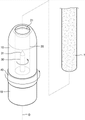
図1は、一実施形態に係わる、回転するヒータを具備したエアロゾル生成装置の斜視図であり、図2は、図1に示された実施形態に係わるエアロゾル生成装置の長手方向の断面図であり、図3は、図1に示された実施形態に係わるエアロゾル生成装置の構成要素の結合関係を示した分離斜視図である。 FIG. 1 is a perspective view of an aerosol generator including a rotating heater according to an embodiment, and FIG. 2 is a longitudinal sectional view of the aerosol generator according to the embodiment shown in FIG. 1. , FIG. 3 is a separated perspective view showing the coupling relationship of the components of the aerosol generator according to the embodiment shown in FIG.
図1ないし図3に示された実施形態に係わる、回転するヒータを具備したエアロゾル生成装置は、シガレット7を収容する通路20を具備する中空状のケース10と、ケース10に回転自在に結合される回転部40と、回転部40と共に回転し、シガレット7を加熱するヒータ30と、を具備する。
The aerosol generator provided with a rotating heater according to the embodiment shown in FIGS. 1 to 3 is rotatably coupled to a
ケース10は、エアロゾル生成装置の外観を形成し、内部空間にさまざまな構成要素を収容しながら保護する機能を遂行する。ケース10は、内部が空いている中空の円筒状を有し、前方端部が外部に開放され、シガレット7が挿入される。
The
ケース10は、電気と熱とを伝達しないプラスチック素材や、表面にプラスチック素材がコーティングされた金属性素材によっても作製される。図示された実施形態において、ケース10が円形の断面を有する円筒状を有するものの、一実施形態は、そのようなケース10の構成によって限定されるものではない。例えば、ケース10は、四角形のような多角形の断面を有する筒状を有することができる。
The
ケース10の内部には、シガレット7を収容する通路20が形成される。シガレット7は、円筒状にも作製され、通路20は、シガレット7の外径に対応する内径を有する。
Inside the
図2及び図3を参照すれば、ケース10は、シガレット7を収容するための通路20を具備する中空状の内筒12と、内筒12の外側に結合される中空状の中間筒11と、中間筒11の外側に結合される外筒13と、を具備する。
Referring to FIGS. 2 and 3, the
内筒12は、シガレット7を収容するための通路20と、外部からシガレット7が挿入されるように、通路20の一端から外部に開放された開口21と、通路20の他端に開放される他側開口22と、を具備する。
The
内筒12に形成された通路20は、シガレット7の形状に対応する円筒状に形成される。本実施形態は、通路20の形状によって制限されず、例えば、通路20の形状が四角形のような多角形の断面を有する筒状にも形成される。
The
内筒12は、外側面に突出し、内筒12の中心軸に対して円周方向に延長するフランジ12pと、フランジ12pから外側に向けて突出する締結突起12cと、を具備する。
The
内筒12の他側端部の他側開口22には、ヒータ30の一側端部31が通過する孔29を具備するキャップ14が結合される。キャップ14は、内筒12の締結突起12cが結合される締結溝14cを具備する。キャップ14が内筒12の他側開口22を覆うように内筒12に結合されれば、キャップ14の締結溝14cに、内筒12の締結突起12cが挿入されることにより、キャップ14が内筒12に固定される。
A
本実施形態は、キャップ14が内筒12と独立した構成要素に作製される構成によって制限されるものではなく、例えば、キャップ14と内筒12は、一体になる1つの構成要素によっても作製される。
The present embodiment is not limited by the configuration in which the
キャップ14は、通路20に収容されるシガレット7の端部と接触する。エアロゾル生成装置のユーザが、シガレット7を通路20に挿入する動作により、シガレット7が通路20に沿って移動していて、シガレット7の端部がキャップ14に逹すれば、シガレット7を手にしているユーザの手に、キャップ14と、シガレット7の端部とが接触する感じが伝達される。従って、ユーザは、シガレット7を手にし、通路20の開口21にシガレット7を押し込む簡単な動作を実施することにより、シガレット7をエアロゾル生成装置に簡便に装着させることができる。
The
内筒12は、ケース10の最も内側に配置され、外部から挿入されるシガレット7が通路20に沿って移動するように、シガレット7の移動経路を提供し、シガレット7を収容する機能を遂行する。内筒12と中間筒11と外筒13とが結合された後、エアロゾル生成装置が使用される間、内筒12は、中間筒11と外筒13とに対し、相対的に移動せず、位置が固定された状態を維持する。
The
ケース10には、シガレット7を加熱する機能を遂行するヒータ30が設けられる。ヒータ30は、ピン(pin)状または棒(rod)状に作製され、ヒータ30の一側端部31は、キャップ14の孔29を介して通路20の内部に配置され、ケース10にシガレット7が収容される場合、ヒータ30の一側端部31がシガレット7の端部に挿入される。
The
キャップ14に形成された孔29の大きさは、ヒータ30の一側端部31の厚みに対応する。例えば、ヒータ30の一側端部31が円形の断面を有する場合、孔29も円形の断面形状を有し、孔29の内径は、ヒータ30の一側端部31の外径に対応するように形成される。
The size of the
本実施形態は、孔29の内径の大きさによって制限されるものではなく、例えば、孔29の内径は、ヒータ30の一側端部31の外径より大きく形成され、孔29の内面がヒータ30の一側端部31の外側面から離隔されてもいる。
The present embodiment is not limited by the size of the inner diameter of the
ヒータ30の他側端部32は、電気配線71を介し、ケース10の後方に配置された電気供給装置72に電気的に連結される。ケース10の後方には、電気供給装置72を取り囲むベース19が連結される。ベース19は、ケース10と共に、回転部40を回転自在に支持する機能を行うことができる。
The
ヒータ30の一側端部31にシガレット7が挿入された状態で、電気供給装置72の電気がヒータ30に供給されれば、ヒータ30が加熱されることにより、シガレット7が加熱される。
If the electricity of the
回転部40は、通路20の長手方向の中心軸Oを中心に回転するように、ケース10に回転自在に結合される。ユーザが回転部40を手で取って回転させれば、回転部40が中心軸Oを中心に回転し、ヒータ30も、回転部40と共に、中心軸Oを中心に回転運動を行う。
The rotating
回転部40は、電気と熱とがあまり伝達しない素材によっても作製される。例えば、回転部40は、ゴムやプラスチックなどの素材によっても作製され、金属素材によって作製された後、ユーザの手が触れる外部表面は、熱及び電気を伝達しない素材によってもコーティングされる。
The rotating
回転部40は、ケース10の外側に結合され、ケース10に対して回転することができる。回転部40は、内部が空いている中空円筒状を有する。回転部40は、内側面に凹状の溝部41を具備する。
The rotating
回転部40の内側には、連結部50が結合される。連結部50は、およそ円形状に作製される。連結部50が回転部40とヒータ30とを連結するので、連結部50が回転部40及びヒータ30と共に回転する。連結部50は、外側に突出した突出部51を具備する。連結部50が回転部40の内側に配置されれば、連結部50の突出部51が、回転部40の溝部41に挿入されることにより、連結部50の回転部40に対する相対的な回転運動が制限される。
A connecting
本実施形態は、連結部50の形状によって制限されるものではなく、例えば、連結部50は、円筒状や棒状などを有することもできる。
The present embodiment is not limited by the shape of the connecting
図示された実施形態において、連結部50に突出部51が設けられ、回転部40に溝部41が設けられる構成だけが説明されたが、本実施形態は、そのような構成によって制限されるものではなく、例えば、連結部50に溝部を設け、回転部40に突出部を設けることもできる。また、連結部50と回転部40は、溝部や突出部を利用する代わりに、接着剤を利用したり、互いに向かる面にねじ面を設けたり、あるいはねじのような締結手段を利用したりして、互いに結合される。
In the illustrated embodiment, only the configuration in which the projecting
連結部50の突出部51は、中間筒11の案内孔11pを通過し、回転部40の溝部41に挿入される。案内孔11pは、中間筒11の中心軸に対する円周方向、すなわち、回転部40の回転中心に対する円周方向に沿ってあらかじめ定められた角度ほど延長して形成される。中間筒11は、案内孔11pの端部に、回転制限部11eを具備する。
The protruding
連結部50は、ヒータ30の一側端部31を通過させる貫通孔52を具備する。また、連結部50の貫通孔52の内壁には、凹状の結合溝53が形成される。ヒータ30の外側面には、結合溝53に対応する形状を有し、突出する結合突起33が設けられる。
The connecting
ヒータ30の一側端部31が連結部50の貫通孔52を通過すれば、ヒータ30の外側面に突出した結合突起33が、連結部50の結合溝53に挿入されることにより、ヒータ30が連結部50に結合され、連結部50とヒータ30とが共に回転する一体を形成する。
When the one-
図示された実施形態において、結合突起33がヒータ30に設けられ、結合溝53が連結部50に設けられる構成だけが説明されたが、本実施形態は、そのような構成によって制限されるものではなく、例えば、ヒータ30に結合溝が設けられ、連結部50に結合突起が設けられてもよい。また、ヒータ30と連結部50は、結合突起と結合溝とを利用する代わり、接着剤を利用したり、互いに向かう面にねじ面を設けたり、あるいはねじのような締結手段を利用したりして、互いに結合される。
In the illustrated embodiment, only the configuration in which the
図4は、図2のエアロゾル生成装置のIV-IVの線に沿って切り取った横方向の断面図であり、図5は、図4のエアロゾル生成装置の一作動状態を図示した横方向の断面図である。 FIG. 4 is a lateral cross-sectional view taken along the line IV-IV of the aerosol generator of FIG. 2, and FIG. 5 is a lateral cross-sectional view illustrating one operating state of the aerosol generator of FIG. It is a figure.
回転部40が回転することにより、回転部40に連結された連結部50とヒータ30とが回転部40と共に回転運動を行う。連結部50の突出部51は、中間筒11の案内孔11pに沿って回転することができるので、突出部51が案内孔11pに沿って運動することができる範囲内において、連結部50と回転部40とヒータ30とが共に回転を行うことができる。
As the rotating
図4に図示された状態において、回転部40が時計方向に回転を行えば、回転部40と連結部50とヒータ30とが共に時計回り方向に回転し、図5に図示された状態になる。案内孔11pの端部には、突出部51の移動を制限する回転制限部11eが位置するので、突出部51が回転制限部11eに接触するまで、回転部40と連結部50とヒータ30とが共に回転することができる。
In the state shown in FIG. 4, if the rotating
図2は、シガレット7がエアロゾル生成装置に装着された状態を図示する。エアロゾル生成装置がタバコ煙発生機能を遂行するためには、図2に図示されているように、シガレット7がケース10の通路20の最下端まで挿入される。ヒータ30の全体長は、約20mmであり、シガレット7に挿入されたヒータ30の一側端部31の長さは、約12mmである。そのような状態では、シガレット7の後方端部が、ヒータ30の一側端部31に挿入されているので、ヒータ30に電気が供給されれば、ヒータ30がシガレット7を加熱し、エアロゾルを発生させる。
FIG. 2 illustrates a state in which the
図1ないし図5に示された実施形態に係わるエアロゾル生成装置においては、ユーザがシガレット7をケース10の通路20に挿入した後、通路20に沿ってシガレット7を押し込む簡便な操作により、エアロゾル生成装置にシガレット7を容易に装着させることができる。また、シガレット7の使用を終えた後には、ユーザがエアロゾル生成装置の上端に突出したシガレット7の上側端部を手にし、通路20の外側にシガレット7を引っ張る簡便な操作により、エアロゾル生成装置からシガレット7を分離させることができる。
In the aerosol generator according to the embodiment shown in FIGS. 1 to 5, the user inserts the
ユーザがエアロゾル生成装置を使用した後、エアロゾル生成装置からシガレット7を除去しなければならない。図2に図示されたエアロゾル生成装置からシガレット7を除去する前、ユーザが回転部40を回転させれば、連結部50と共にヒータ30が中心軸Oを中心に回転をする。ヒータ30が回転する間、ケース10に対するシガレット7の位置は、変わらずに維持される。
After the user has used the aerosol generator, the
シガレット7がヒータ30によって加熱される間、シガレット7で発生したタバコ物質(残留物)が、ヒータ30とシガレット7との接触面に凝縮されて付着する。図2に図示されているように、シガレット7にヒータ30の一側端部31が挿入された状態でヒータ30が回転を行えば、シガレット7とヒータ30との接触面に付着したタバコ物質によって互いに付着した状態を維持したシガレット7とヒータ30との接触面が容易に分離される。
While the
ヒータ30が回転することにより、ヒータ30とシガレット7との接触面が互いに分離されれば、ユーザがシガレット7を取り、ケース10の通路20の外部に抽出することにより、使用されたシガレット7をエアロゾル生成装置のケース10から完全に分離させることができる。
When the contact surfaces of the
従来のエアロゾル生成装置においては、エアロゾル生成装置からシガレットを分離するとき、ユーザがエアロゾル生成装置から単に抜き取る方式を利用するので、シガレットとヒータとの間に存在するタバコ物質がヒータに付着する場合が多い。 In the conventional aerosol generator, when the cigarette is separated from the aerosol generator, the user simply removes it from the aerosol generator, so that the tobacco substance existing between the cigarette and the heater may adhere to the heater. many.
しかし、前述の実施形態に係わるエアロゾル生成装置においては、シガレット7をエアロゾル生成装置から分離する前、まず、シガレット7をケース10に対して固定された位置に維持した状態で回転部40を回転させることにより、ヒータ30を回転させる。
However, in the aerosol generator according to the above-described embodiment, before the
ヒータ30が回転する間、シガレット7がケース10に対して固定された状態を維持し、シガレット7のケース10に対する位置が変化しないので、タバコ物質によって固着していたヒータ30とシガレット7との接触面が容易に分離される。また、そのような過程において、シガレット7とヒータ30との間に存在した残留物がシガレット7に付着した状態が維持される。
While the
前述の作動を介して、ヒータ30とシガレット7とがまず分離された後、ユーザがシガレット7を取り、エアロゾル生成装置からシガレット7を分離することができるので、シガレット7と共に、シガレット7に付着している残留物をエアロゾル生成装置の外部に手軽に排出させることができる。
Through the above-mentioned operation, the
図6は、他の実施形態に係わるエアロゾル生成装置の横方向の断面図である。 FIG. 6 is a lateral sectional view of an aerosol generator according to another embodiment.
図6に示された実施形態に係わるエアロゾル生成装置は、突出部51が移動する経路上に設けられ、突出部51の移動に対して弾性力(抵抗力)を付与する加圧部70を具備する。加圧部70の一端70aは、中間筒11に連結され、加圧部70の他端70bは、突出部51に連結される。加圧部70は、スプリングでもあり、突出部51が移動する方向に対して反対となる方向の弾性力を付与することにより、回転部40と共に、連結部50が回転運動を行った後、回転部40と連結部50とが本来の初期位置で復帰することができる。
The aerosol generator according to the embodiment shown in FIG. 6 is provided on a path in which the
本実施形態は、加圧部70の構成によって制限されるものではなく、例えば、液体やガスを利用した圧縮式シリンダを利用し、弾性加圧部が具現されもする。
The present embodiment is not limited by the configuration of the pressurizing
図7は、さらに他の実施形態に係わるエアロゾル生成装置の長手方向の断面図であり、図8は、図7に示された実施形態に係わるエアロゾル生成装置の構成要素の結合関係を概略的に図示した斜視図である。 FIG. 7 is a longitudinal sectional view of the aerosol generator according to still another embodiment, and FIG. 8 schematically shows the coupling relationship of the components of the aerosol generator according to the embodiment shown in FIG. 7. It is a perspective view illustrated.
図7及び図8に示された実施形態に係わる、回転するヒータを具備したエアロゾル生成装置は、シガレット7を収容する通路20を具備する中空状のケース110と、ケース110に回転自在に結合される回転部140と、回転部140と共に回転し、シガレット7を加熱するヒータ30と、を具備する。
The aerosol generator with a rotating heater according to the embodiment shown in FIGS. 7 and 8 is rotatably coupled to the
ケース110は、中空の円筒状にも作製され、ケース110は、シガレット7の外径に対応する内径を有し、シガレット7を収容する通路20を有する。通路20は、通路20の一端から外部に開放された開口21と、通路20に収容されたシガレット7の下側端部を支持する底部22dと、を具備する。
The
ケース110は、ヒータ30の一側端部31が通過するように、通路20と連結される孔29を具備する。孔29は、通路20の底部22dの中心領域を貫通するように形成される。
The
ケース110には、シガレット7を加熱する機能を遂行するヒータ30が設けられる。ヒータ30の一側端部31は、孔29を介して、通路20の内部に配置され、ケース10にシガレット7が収容される場合、ヒータ30の一側端部31がシガレット7の端部に挿入される。
The
ヒータ30の他側端部は、電気配線71を介して、ケース110の後方に配置された電気供給装置72に電気的に連結される。ケース110の後方には、電気供給装置72を取り囲むベース119が連結される。ベース119は、ケース110と共に、回転部140を回転自在に支持する機能を行うことができる。
The other end of the
ヒータ30の一側端部31にシガレット7が挿入された状態で、電気供給装置72の電気がヒータ30に供給されれば、ヒータ30が加熱されることにより、シガレット7が加熱される。
If the electricity of the
回転部140は、通路20の長手方向の中心軸Oを中心に回転するように、ケース110に回転自在に結合される。ユーザが回転部140を手にして回転させれば、回転部140が中心軸Oを中心に回転し、ヒータ30も、回転部140と共に、中心軸Oを中心に回転運動を行う。
The rotating
回転部140は、ケース110に対して回転するように結合される。回転部140は、内部が空いている中空円筒状を有する。
The rotating
回転部140は、ヒータ30の一側端部31を通過させる貫通孔142を具備する。また回転部140は、内側面に溝部141を具備する。ヒータ30は、回転部140の溝部141に対応する形状を有し、ヒータ30の外側面から外側に突出した突出部133を具備する。
The rotating
ヒータ30の一側端部31が回転部140の貫通孔142を通過すれば、ヒータ30の外側面に突出した突出部133が回転部140の溝部141に挿入されることにより、ヒータ30が回転部140に結合され、回転部140とヒータ30とが共に回転する一体を形成する。
When one
図示された実施形態において、ヒータ30に突出部133が設けられ、回転部140に溝部141が設けられる構成だけが説明されたが、本実施形態は、そのような構成によって制限されるものではなく、例えば、ヒータ30に溝部が設けられ、回転部に突出部が設けられてもよい。
In the illustrated embodiment, only the configuration in which the
回転部140のケース110に向かう面には、移動突起147が設けられる。ケース110の回転部140に向かう面には、移動突起147が挿入される案内溝部117が設けられる。案内溝部117は、回転部140の回転中心に対して、円周方向に沿って既設定の距離ほど延長されるように形成される。
A moving
ベース119は、回転部140に向けて突出するフランジ148を具備する。フランジ148は、回転部140の回転中心である中心軸Oの円周方向に沿って延設される。フランジ148は、ケース110の後方に結合されたベース119から突出し、回転部140の円周方向に延設された連結通路140sを貫通することにより、ケース110のフランジ溝118に結合される。従って、回転部140は、ケース110とベース119との間において、フランジ148により、回転中心軸Oに対して回転自在に支持される。
The
回転部140がケース110に対して回転する間、回転部140の移動突起147は、ケース110の案内溝部117に挿入された状態で、案内溝部117に沿って移動する。移動突起147が、案内溝部117の端部に達すれば、案内溝部117の端部が、移動突起147がそれ以上移動しないように制限するので、回転部140の回転運動が制限される。
While the rotating
回転部140が回転することにより、回転部140に連結されたヒータ30が、回転部140と共に回転運動を行う。回転部140の移動突起147は、ケース110の案内溝部117に沿って回転することができるので、移動突起147が、案内溝部117に沿って運動することができる範囲内において、回転部140とヒータ30とが共に回転を行うことができる。
As the
図7及び図8に示された実施形態に係わるエアロゾル生成装置において、シガレット7を除去する前、ユーザが回転部140を回転させれば、回転部140と共にヒータ30が中心軸Oを中心に回転する。ヒータ30が回転する間、ケース110に対するシガレット7の位置は変わらずに維持される。
In the aerosol generator according to the embodiment shown in FIGS. 7 and 8, if the user rotates the
シガレット7にヒータ30の一側端部31が挿入された状態で、ヒータ30が回転を行えば、シガレット7とヒータ30との接触面に付着したタバコ物質によって互いに付着した状態を維持したシガレット7とヒータ30との接触面が容易に分離される。
When the
ヒータ30が回転することにより、ヒータ30とシガレット7との接触面が互いに分離されれば、ユーザがシガレット7を取り、ケース110の通路20の外部に抽出することにより、使用されたシガレット7をエアロゾル生成装置のケース110から完全に分離させることができる。
When the contact surfaces of the
前述の作動を介して、ヒータ30がまずシガレット7から分離された後、ユーザがシガレット7を取り、エアロゾル生成装置からシガレット7を分離させることができるので、シガレット7と共にシガレット7に付着している残留物を、エアロゾル生成装置の外部に手軽に排出させることができる。
Through the above-mentioned operation, the
以下の図9ないし図21A~図21Fに図示された実施形態は、前述の図1ないし図8に図示された実施形態に係わるエアロゾル生成装置に適用される変形されたエアロゾル生成装置とエアロゾル生成方法とを図示する。 The embodiments shown in FIGS. 9 to 21A to 21F below are a modified aerosol generation device and an aerosol generation method applied to the aerosol generation device according to the embodiment shown in FIGS. 1 to 8 described above. And are illustrated.
図9ないし図21A~図21Fにおいて、構成要素を示す番号は、図1ないし図8で使用された番号と関連性なしに独立して使用された。従って、図1ないし図8において、構成要素を示した番号と、図9ないし図21A~図21Fで構成要素を示す番号は、互いに独立して異なる構成要素を示すために使用されたものであると理解されなければならない。 In FIGS. 9 to 21A to 21F, the numbers indicating the components are used independently of the numbers used in FIGS. 1 to 8. Therefore, in FIGS. 1 to 8, the numbers indicating the components and the numbers indicating the components in FIGS. 9 to 21A to 21F are used to indicate different components independently of each other. Must be understood.
図9は、さらに他の実施形態に係わるエアロゾル生成装置の一例を図示した構成図である。 FIG. 9 is a configuration diagram illustrating an example of an aerosol generation device according to still another embodiment.
図9を参照すれば、エアロゾル生成装置1(以下、ホルダとする)は、バッテリ110、制御部120及びヒータ130を含む。また、ホルダ1は、ケース140によって形成された内部空間を含む。ホルダ1の内部空間には、シガレットが挿入される。
Referring to FIG. 9, the aerosol generator 1 (hereinafter referred to as a holder) includes a
図9に図示されたホルダ1には、本実施形態と係わる構成要素だけが図示されている。従って、図9に図示された構成要素以外に、他の汎用的な構成要素がホルダ1にさらに含まれてもよいということは、本実施形態と係わる技術分野において当業者であるならば、理解することができるであろう。
In the
シガレットがホルダ1に挿入されれば、ホルダ1は、ヒータ130を加熱する。シガレット内のエアロゾル生成物質は、加熱されたヒータ130によって温度が上昇し、それにより、エアロゾルが生成される。生成されたエアロゾルは、シガレットのフィルタを介してユーザに伝達される。ただし、該シガレットがホルダ1に挿入されていない場合にも、ホルダ1は、ヒータ130を加熱することができる。
If the cigarette is inserted into the
ケース140は、ホルダ1から分離される。例えば、ユーザが、ケース140を、時計回り方向または反時計回り方向に回すことにより、ケース140は、ホルダ1から分離される。
The
また、ケース140の末端141が形成する孔の直径は、ケース140とヒータ130とによって形成された空間の直径に比べ、小さく作製され、その場合、ホルダ1に挿入されるシガレットのガイド役割を行うことができる。
Further, the diameter of the hole formed by the
バッテリ110は、ホルダ1が動作するのに利用される電力を供給する。例えば、バッテリ110は、ヒータ130が加熱されるように電力を供給することができ、制御部120が動作するのに必要な電力を供給することができる。また、バッテリ110は、ホルダ1に設けられたディスプレイ、センサ、モータなどが動作するのに必要な電力を供給することができる。
The
バッテリ110は、リチウムリン酸鉄(LiFePO4)バッテリでもあるが、前述の例に限定されるものではない。例えば、バッテリ110は、酸化リチウムコバルト(LiCoO2)バッテリ、リチウムチタン酸塩バッテリなどが該当する。
The
また、バッテリ110は、直径が10mmであり、長さが37mmである円柱状でもあるが、それに限定されるものではない。バッテリ110の容量は、120mAh以上でもあり、充電が可能なバッテリであるか、あるいは1回使用バッテリでもある。例えば、バッテリ110が充電が可能である場合、バッテリ110の充電率(C-rate)は、10C、放電率(C-rate)は、16Cないし20Cでもあるが、それらに限定されるものではない。また、安定した使用のために、バッテリ110は、充放電が8,000回進められた場合にも、全体容量の80%以上が確保されるように作製される。
Further, the
ここで、バッテリ110の満充電及び完全放電のいかんは、バッテリ110に保存された電力が、バッテリ110の全体容量対比で、どれほどのレベルであるかということによっても判断される。例えば、バッテリ110に保存された電力が、全体容量の95%以上である場合、バッテリ110が満充電されたと判断される。また、バッテリ110に保存された電力が、全体容量の10%以下である場合、バッテリ110が完全放電されたと判断される。しかし、バッテリ110の満充電及び完全放電のいかんに係わる判断基準は、前述の例に限定されるものではない。
Here, whether the
ヒータ130は、バッテリ110から供給された電力によって加熱される。シガレットがホルダ1に挿入されれば、ヒータ130は、該シガレットの内部に位置する。従って、加熱されたヒータ130は、シガレット内のエアロゾル生成物質の温度を上昇させる。
The
ヒータ130は、円柱と円錐とが組み合わされた形状でもある。例えば、ヒータ130は、直径が約2mm、長さが約23mmである円柱状を有し、ヒータ130の末端2131は、鋭角に仕上げられるが、それに限定されるものではない。言い換えれば、ヒータ130は、シガレットの内部に挿入される形態であるならば、制限なしに該当する。また、ヒータ130は、一部分だけ加熱されもする。例えば、ヒータ130の長さが23mmであると仮定すれば、ヒータ130の末端131から12mmだけ加熱され、ヒータ130の残り部分は、加熱されない。
The
ヒータ130は、電気抵抗性ヒータでもある。例えば、ヒータ130には、電気伝導性トラック(track)を含み、該電気伝導性トラックに電流が流れることにより、ヒータ130が加熱される。
The
安定した使用のために、ヒータ130には、3.2V、2.4A、8Wの規格による電力が供給されるが、それらに限定されるものではない。例えば、ヒータ130に電力が供給される場合、ヒータ130の表面温度は、400℃以上に上昇する。ヒータ130に電力が供給され始めたときから15秒が超える前、ヒータ130の表面温度は、約350℃まで上昇する。
For stable use, the
ホルダ1には、別途の温度感知センサが具備される。または、ホルダ1に温度感知センサが具備されず、ヒータ130が、温度感知センサの役割を行うこともできる。例えば、ヒータ130には、発熱のための第1電気伝導性トラック以外に、温度感知のための第2電気伝導性トラックがさらに含まれてもよい。
The
例えば、該第2電気伝導性トラックにかかる電圧、及び第2電気伝導性トラックに流れる電流が測定されれば、抵抗(R)が決定される。このとき、下記数式1により、第2電気伝導性トラックの温度(T)が決定される。
For example, the resistance (R) is determined by measuring the voltage applied to the second electric conductive track and the current flowing through the second electric conductive track. At this time, the temperature (T) of the second electrically conductive track is determined by the following
![]()
![]()
数式1で、Rは、第2電気伝導性トラックの現在抵抗値を意味し、R0は、温度T0(例えば、0℃)での抵抗値を意味し、αは、第2電気伝導性トラックの抵抗温度係数を意味する。伝導性物質(例えば、金属)は、固有の抵抗温度係数を有しているが、第2電気伝導性トラックを構成する伝導性物質により、αは、事前に決定されている。従って、第2電気伝導性トラックの抵抗(R)が決定される場合、前記数式1により、第2電気伝導性トラックの温度(T)が演算される。
In
ヒータ130は、少なくとも1つの電気伝導性トラック(第1電気伝導性トラック及び第2電気伝導性トラック)によっても構成される。例えば、ヒータ130は、2個の第1電気伝導性トラック、及び1個または2個の第2電気伝導性トラックによっても構成されるが、それらに限定されるものではない。
The
該電気伝導性トラックは、電気抵抗性物質を含む。一例として、該電気伝導性トラックは、金属物質によっても作製される。他の例として、該電気伝導性トラックは、電気伝導性セラミック物質、炭素、金属合金、またはセラミック物質と金属との合成物質によっても作製される。 The electrically conductive track contains an electrically resistant material. As an example, the electrically conductive track is also made of a metallic material. As another example, the electrically conductive track is also made of an electrically conductive ceramic material, carbon, a metal alloy, or a synthetic material of a ceramic material and a metal.
また、ホルダ1は、温度感知センサの役割を行う電気伝導性トラック及び温度感知センサをいずれも含んでもよい。
Further, the
制御部120は、ホルダ1の動作を全般的に制御する。具体的には、制御部120は、バッテリ110及びヒータ130だけではなく、ホルダ1に含まれた他の構成の動作を制御する。また、制御部120は、ホルダ1の構成それぞれの状態を確認し、ホルダ1が動作可能な状態であるか否かということを判断することもできる。
The
制御部120は、少なくとも1つのプロセッサを含む。該プロセッサは、多数の論理ゲートのアレイによっても具現され、汎用的なマイクロプロセッサと、該マイクロプロセッサで実行されるプログラムが保存されたメモリとの組み合わせによっても具現される。また、他の形態のハードウェアによっても具現されるということは、本実施形態が属する技術分野において当業者であるならば、理解することができるであろう。
The
例えば、制御部120は、ヒータ130の動作を制御することができる。制御部120は、ヒータ130が所定温度まで加熱されるか、あるいは適切な温度を維持するように、ヒータ130に供給される電力の量、及び電力が供給される時間を制御することができる。また、制御部120は、バッテリ110の状態(例えば、バッテリ110の残量など)を確認し、必要な場合、お知らせ信号を生成することができる。
For example, the
また、制御部120は、ユーザのパフの有無、及びパフの強度を確認することができ、パフの数をカウンティングすることができる。また、制御部120は、ホルダ1が作動している時間を続けて確認することができる。また、制御部120は、後述するクレードル2がホルダ1と結合されたか否かということを確認し、クレードル2とホルダ1との結合または分離により、ホルダ1の動作を制御することができる。
In addition, the
一方、ホルダ1は、バッテリ110、制御部120及びヒータ130以外に、汎用的な構成をさらに含んでもよい。
On the other hand, the
例えば、ホルダ1は、視覚情報の出力が可能なディスプレイ、または触覚情報の出力のためのモータを含んでもよい。一例として、ホルダ1にディスプレイが含まれる場合、制御部120は、ディスプレイを介して、ユーザにホルダ1の状態に係わる情報(例えば、ホルダの使用可能いかんなど)、ヒータ130に係わる情報(例えば、予熱開始、予熱進行、予熱完了など)、バッテリ110と係わる情報(例えば、バッテリ110の残余容量、使用可能いかんなど)、ホルダ1のリセットと係わる情報(例えば、リセット時期、リセット進行、リセット完了など)、ホルダ1の掃除と係わる情報(例えば、掃除時期、掃除必要、掃除進行、掃除完了など)、ホルダ1の充電と係わる情報(例えば、充電必要、充電進行、充電完了など)、パフと係わる情報(例えば、パフ回数、パフ終了予告など)、または安全と係わる情報(例えば、使用時間経過など)などを伝達することができる。他の例として、ホルダ1にモータが含まれる場合、制御部120は、モータを利用し、振動信号を生成することにより、ユーザに前述の情報を伝達することができる。
For example, the
また、ホルダ1は、ユーザがホルダ1の機能を制御することができる少なくとも1つの入力装置(例えば、ボタン)、及び/またはクレードル2と結合される端子を含んでもよい。例えば、ユーザは、ホルダ1の入力装置を利用し、多様な機能を行うことができる。ユーザが入力装置を押す回数(例えば、1回、2回など)、または入力装置を押している時間(例えば、0.1秒、0.2秒など)を調節することにより、ホルダ1の複数機能のうち所望機能を実行することができる。ユーザが入力装置を作動させることにより、ホルダ1は、ヒータ130を予熱する機能、ヒータ130の温度を調節する機能、シガレットが挿入される空間を掃除する機能、ホルダ1が作動可能な状態であるか否かということを点検する機能、バッテリ110の残量(可用電力)を表示する機能、ホルダ1のリセット機能などが遂行される。しかし、ホルダ1の機能は、前述の例に限定されるものではない。
The
また、ホルダ1は、パフ感知センサ、温度感知センサ及び/またはシガレット挿入感知センサを含んでもよい。例えば、該パフ感知センサは、一般的な圧力センサによっても具現され、該シガレット挿入感知センサは、一般的な静電容量型センサまたは抵抗センサによっても具現される。また、ホルダ1は、シガレットが挿入された状態においても、外部空気が流入/流出される構造にも作製される。
The
図10A及び図10Bは、ホルダの一例をさまざまな側面で図示した図面である。 10A and 10B are drawings illustrating an example of a holder on various sides.
図10Aは、ホルダ1を第1方向から見た例を図示した図面である。図10Aに図示されているように、ホルダ1は、円筒状にも作製されるが、それに限定されるものではない。ホルダ1のケース140は、ユーザの動作によっても分離され、ケース140の末端141にシガレットが挿入される。また、ホルダ1には、ユーザがホルダ1を制御することができるボタン150、及び画面(image)が出力されるディスプレイ2160が含まれもする。
FIG. 10A is a drawing illustrating an example of the
図10Bは、ホルダ1を第2方向から見た例を図示した図面である。ホルダ1は、クレードル2と結合される端子170を含んでもよい。ホルダ1の端子170がクレードル2の端子260と結合することにより、クレードル2のバッテリ210が供給する電力により、ホルダ1のバッテリ110が充電される。また、端子170と端子260とを介して、クレードル2のバッテリ210が供給する電力により、ホルダ1が動作することもでき、ホルダ1とクレードル2との間に通信(信号の送受信)が可能である。例えば、端子170は、4個のマイクロピン(pin)によっても構成されるが、それに限定されるものではない。
FIG. 10B is a drawing illustrating an example of the
図11は、クレードルの一例を図示した構成図である。 FIG. 11 is a block diagram illustrating an example of a cradle.
図11を参照すれば、クレードル2は、バッテリ210及び制御部220を含む。また、クレードル2は、ホルダ1が挿入される内部空間230を含む。例えば、内部空間230は、クレードル2の一側面にも形成される。従って、クレードル2が別途のふたを含まないとしても、ホルダ1がクレードル2に挿入されて固定される。
Referring to FIG. 11, the
図11に図示されたクレードル2には、本実施形態と係わる構成要素だけが図示されている。従って、図11に図示された構成要素以外に、他の汎用的な構成要素が、クレードル2にさらに含まれもすることは、本実施形態と係わる技術分野で当業者であるならば、理解することができるであろう。
In the
バッテリ210は、クレードル2が動作するのに利用される電力を供給する。また、バッテリ210は、ホルダ1のバッテリ110を充電する電力を供給することができる。例えば、ホルダ1がクレードル2に挿入され、ホルダ1の端子170と、クレードル2の端子260とが結合する場合、クレードル2のバッテリ210は、ホルダ1のバッテリ110に電力を供給することができる。
The
また、ホルダ1とクレードル2とが結合された場合、バッテリ210は、ホルダ1が動作するのに利用される電力を供給することができる。例えば、ホルダ1の端子170と、クレードル2の端子260とが結合されれば、ホルダ1のバッテリ110が放電したか否かということを問わず、ホルダ1は、クレードル2のバッテリ210が供給する電力を利用し、動作することができる。
Further, when the
バッテリ210種類の例は、図9を参照して説明したバッテリ110の例と同一である。バッテリ210の容量は、3,000mAh以上にもなる。ただし、バッテリ210の容量は、前述の例に限定されるものではない。
The example of the
制御部220は、クレードル2の動作を全般的に制御する。制御部220は、クレードル2の全ての構成の動作を制御することができる。また、制御部220は、ホルダ1とクレードル2とが結合されたか否かということを判断し、クレードル2とホルダ1との結合または分離により、クレードル2の動作を制御することができる。
The
例えば、ホルダ1とクレードル2とが結合されれば、制御部220は、バッテリ210の電力をホルダ1に供給することにより、バッテリ110を充電したり、ヒータ130を加熱させたりすることができる。従って、バッテリ110の残量が少ない場合にも、ユーザは、ホルダ1とクレードル2とを結合し、連続的に吸煙することができる。
For example, if the
制御部120は、少なくとも1つのプロセッサを含む。該プロセッサは、多数の論理ゲートのアレイによっても具現され、汎用的なマイクロプロセッサと、そのマイクロプロセッサで実行されるプログラムが保存されたメモリとの組み合わせによっても具現される。また、他の形態のハードウェアによっても具現されるということは、本実施形態が属する技術分野で当業者であるならば、理解することができるであろう。
The
一方、クレードル2は、バッテリ210及び制御部220以外に、汎用的な構成をさらに含んでもよい。例えば、クレードル2は、視覚情報の出力が可能なディスプレイを含んでもよい。例えば、クレードル2にディスプレイが含まれる場合、制御部220は、ディスプレイに表示される信号を生成することにより、ユーザに、バッテリ210(例えば、バッテリ210の残余容量、使用可能いかんなど)と係わる情報、クレードル2のリセット(例えば、リセット時期、リセット進行、リセット完了など)と係わる情報、ホルダ1の掃除(例えば、掃除時期、掃除必要、掃除進行、掃除完了など)と係わる情報、クレードル2の充電(例えば、充電必要、充電進行、充電完了など)と係わる情報などを伝達することができる。
On the other hand, the
また、クレードル2は、ユーザがクレードル2の機能を制御することができる少なくとも1つの入力装置(例えば、ボタン)、ホルダ1と結合する端子260、及び/またはバッテリ210の充電のためのインターフェース(例えば、USBポートなど)を含んでもよい。
The
例えば、ユーザは、クレードル2の入力装置を利用し、多様な機能を実行することができる。ユーザが入力装置を押す回数、または入力装置を押している時間を調節することにより、クレードル2の複数機能のうち所望する機能を実行することができる。ユーザが入力装置を作動させることにより、クレードル2は、ホルダ1のヒータ130を予熱する機能、ホルダ1のヒータ130の温度を調節する機能、ホルダ1内のシガレットが挿入される空間を掃除する機能、クレードル2が作動可能な状態であるか否かということを点検する機能、クレードル2のバッテリ210の残量(可用電力)を表示する機能、クレードル2のリセット機能などが遂行されもする。しかし、クレードル2の機能は、前述の例に限定されるものではない。
For example, the user can use the input device of the
図12A及び図12Bは、クレードルの一例をさまざまな側面で図示した図面である。 12A and 12B are drawings illustrating an example of a cradle in various aspects.
図12Aは、クレードル2を第1方向から見た例を図示した図面である。クレードル2の一側面には、ホルダ1が挿入される空間230がある。また、クレードル2がふたのような別途の固定手段を含まないとしても、ホルダ1がクレードル2に挿入されて固定される。また、クレードル2には、ユーザがクレードル2を制御することができるボタン240、及び画面(image)が出力されるディスプレイ250が含まれもする。
FIG. 12A is a drawing illustrating an example of the
図12Bは、クレードル2を第2方向から見た例を図示した図面である。クレードル2には、挿入されたホルダ1と結合される端子260を含んでもよい。端子260がホルダ1の端子170と結合することにより、クレードル2のバッテリ210が供給する電力により、ホルダ1のバッテリ110が充電される。また、端子170と端子260とを介して、クレードル2のバッテリ210が供給する電力により、ホルダ1が動作することもでき、ホルダ1とクレードル2との信号送受信が可能である。例えば、端子260は、4個のマイクロピン(pin)によっても構成されるが、それに限定されるものではない。
FIG. 12B is a drawing illustrating an example of the
図12A及び図12Bを参照して述べたように、ホルダ1は、クレードル2の内部空間230に挿入される。また、ホルダ1は、クレードル2の内部に完全に挿入され、クレードル2に挿入された状態でもチルトされる。以下、図13及び図15Bを参照し、ホルダ1がクレードル2に挿入される例について説明する。
As described with reference to FIGS. 12A and 12B, the
図13は、ホルダがクレードルに挿入される一例を図示した図面である。 FIG. 13 is a drawing illustrating an example in which the holder is inserted into the cradle.
図13を参照すれば、ホルダ1がクレードル2に挿入された一例が図示されている。ホルダ1が挿入される空間230がクレードル2の一側面に存在するので、挿入されたホルダ1は、クレードル2の他の側面によって外部に露出されない。従って、クレードル2は、ホルダ1を外部に露出させないための他の構成(例えば、ふた)を含まなくともよい。
Referring to FIG. 13, an example in which the
クレードル2には、ホルダ1との結着強度を高めるために、少なくとも1つの結着部材271,272が含まれもする。また、ホルダ1にも、少なくとも1つの結着部材181が含まれもする。ここで、結着部材181,271,272は、磁石にもなるが、それに限定されるものではない。図13には、説明の便宜のために、ホルダ1が1つの結着部材181を含み、クレードル2が2つの結着部材271,272を含むように図示されているが、結着部材181,271,272の数は、それに限定されるものではない。
The
ホルダ1は、第1位置に、結着部材181を含んでもよく、クレードル2は、第2位置及び第3位置に、それぞれ結着部材271,272を含んでもよい。そのとき、第1位置と第3位置は、ホルダ1がクレードル2に挿入される場合、互いに対面する位置でもある。
The
ホルダ1及びクレードル2に結着部材181,271,272が含まれることにより、ホルダ1がクレードル2の一側面に挿入されても、ホルダ1とクレードル2とがさらに強く結着される。言い換えれば、ホルダ1及びクレードル2に、端子170,260以外に、結着部材181,271,272がさらに含まれることにより、ホルダ1とクレードル2とがさらに強く結着される。従って、クレードル2に別途の構成(例えば、ふた)がないとしても、挿入されたホルダ1が、クレードル2から容易に分離されない。
By including the binding members 181,271,272 in the
また、端子170,260及び/または結着部材181,271,272により、ホルダ1がクレードル2に完全に挿入されたと判断されれば、制御部220は、バッテリ210の電力を利用し、ホルダ1のバッテリ110を充電することができる。
Further, if it is determined by the
図14は、ホルダがクレードルに挿入された状態でチルトされる一例を図示した図面である。 FIG. 14 is a drawing illustrating an example in which the holder is tilted while being inserted into the cradle.
図14を参照すれば、ホルダ1がクレードル2の内部でチルトされている。ここで、該チルトは、ホルダ1がクレードル2に挿入された状態から一定角度傾けられることを意味する。
Referring to FIG. 14, the
図13に図示されているように、ホルダ1がクレードル2に完全に挿入される場合、ユーザは、喫煙をすることができない。言い換えれば、ホルダ1がクレードル2に完全に挿入されれば、ホルダ1にシガレットが挿入されない。従って、ホルダ1がクレードル2に完全に挿入された状態においては、ユーザが喫煙をすることができない。
As illustrated in FIG. 13, when the
図14に図示されているように、ホルダ1がチルトされれば、ホルダ1の末端141が外部に露出される。従って、ユーザは、末端141にシガレットを挿入し、生成されたエアロゾルを吸入(喫煙)することができる。チルト角θは、シガレットがホルダ1の末端141に挿入されるとき、シガレットが折れたり毀損されたりしないように、十分な角度が確保される。例えば、ホルダ1は、末端141に含まれたシガレット挿入孔全体が外部に露出される最小角度、またはそれより大きい角度にもチルトされる。例えば、チルト角θの範囲は、0゜超過180゜以下にもなり、望ましくは、10゜以上90゜以下にもなる。さらに望ましくは、チルト角θの範囲は、10゜以上20゜以下、10゜以上30゜以下、10゜以上40゜以下、10゜以上50゜以下、または10゜以上60゜以下にもなる。
As shown in FIG. 14, when the
また、ホルダ1がチルトされても、ホルダ1の端子170と、クレードル2の端子260は、互いに結合されている。従って、ホルダ1のヒータ130は、クレードル2のバッテリ210が供給する電力によって加熱されもする。従って、ホルダ1のバッテリ110の残量が少ないか、あるいはない場合にも、ホルダ1は、クレードル2のバッテリ210を利用し、エアロゾルを生成することができる。
Further, even if the
図14には、ホルダ1が1つの結着部材182を含み、クレードル2が2つの結着部材273,274を含む例が図示されている。例えば、結着部材182,273,274それぞれの位置は、図13を参照して説明した通りである。もし結着部材182,273,274が磁石であると仮定するならば、結着部材274の磁石強度が、結着部材273の磁石強度よりも大きくなる。従って、ホルダ1がチルトされても、結着部材182及び結着部材274により、ホルダ1は、クレードル2と完全に分離されない。
FIG. 14 illustrates an example in which the
また、端子170,260及び/または結着部材182,273,274により、ホルダ1がチルトされたと判断されれば、制御部220は、バッテリ210の電力を利用し、ホルダ1のヒータ130を加熱したり、バッテリ110を充電したりすることができる。
Further, if it is determined by the
図15A及び図15Bは、ホルダがクレードルに挿入された例を図示した図面である。 15A and 15B are drawings illustrating an example in which the holder is inserted into the cradle.
図15Aには、ホルダ1がクレードル2に完全に挿入された例が図示されている。ホルダ1がクレードル2に完全に挿入される場合、ユーザがホルダ1に接触することを最小化させるために、クレードル2の内部空間230が十分に確保されるようにも作製される。ホルダ1がクレードル2に完全に挿入されれば、制御部220は、ホルダ1のバッテリ110が充電されるように、バッテリ210の電力をホルダ1に供給する。
FIG. 15A illustrates an example in which the
図15Bには、ホルダ1がクレードル2に挿入された状態でチルトされた例が図示されている。ホルダ1がチルトされれば、制御部220は、ホルダ1のバッテリ110が充電されるか、あるいはホルダ1のヒータ130が加熱されるように、バッテリ210の電力をホルダ1に供給する。
FIG. 15B shows an example in which the
図16は、ホルダ及びクレードルが動作する一例について説明するためのフローチャートである。 FIG. 16 is a flowchart for explaining an example in which the holder and the cradle operate.
図16に図示されたエアロゾルを生成する方法は、図9に図示されたホルダ1、または図11に図示されたクレードル2において、時系列的に処理される段階で構成される。従って、以下で省略された内容であるとしても、図9に図示されたホルダ1、及び図11に図示されたクレードル2について、以上で記述された内容は、図16の方法にも適用されるということが分かる。
The method of producing the aerosol shown in FIG. 16 comprises the steps of being processed in chronological order in the
810段階において、ホルダ1は、クレードル2に挿入されたか否かということを判断する。例えば、制御部120は、ホルダ1及びクレードル2の端子170,260が互いに連結されたか否かということ、及び/または結着部材181,271,272が動作するか否かということにより、ホルダ1がクレードル2に挿入されたか否かということを判断することができる。
At
ホルダ1がクレードル2に挿入された場合には、820段階に進み、ホルダ1がクレードル2から分離された場合には、830段階に進む。
If the
820段階において、クレードル2は、ホルダ1がチルトされたか否かということを判断する。例えば、制御部220は、ホルダ1及びクレードル2の端子170,260が互いに連結されたか否かということ、及び/または結着部材182,273,274が動作するか否かということにより、ホルダ1がチルトされたか否かということを判断することができる。
At the 820 stage, the
820段階においては、クレードル2がホルダ1のチルトいかんを判断すると説明したが、それに限定されるものではない。言い換えれば、ホルダ1のチルトいかんは、ホルダ1の制御部120によっても判断される。
In the 820 stage, it has been explained that the
ホルダ1がチルトされた場合には、840段階に進み、ホルダ1がチルトされていない場合(すなわち、ホルダ1がクレードル2に完全に挿入された場合)には、870段階に進む。
If the
830段階において、ホルダ1は、ホルダ1の使用条件を満足するか否かということを判断する。例えば、制御部120は、バッテリ110の残量、及びホルダ1の他の構成が正常に動作することができるか否かということをチェックすることにより、使用条件が満足されたか否かということを判断することができる。
At the 830 stage, the
ホルダ1の使用条件が満足された場合には、840段階に進み、そうではない場合には、手続きを終了する。
If the conditions for using the
840段階において、ホルダ1は、ユーザに使用可能状態であるということを知らせる。例えば、制御部120は、ホルダ1のディスプレイに使用可能であるということを知らせる画面(image)を出力することもでき、ホルダ1のモータを制御し、振動信号を生成することもできる。
At 840 steps, the
850段階において、ヒータ130が加熱される。一例として、ホルダ1がクレードル2から分離された場合、ホルダ1のバッテリ110の電力により、ヒータ130が加熱されもする。他の例として、ホルダ1がチルトされた場合、クレードル2のバッテリ210の電力により、ヒータ130が加熱されもする。
At 850 steps, the
ホルダ1の制御部120、またはクレードル2の制御部220は、ヒータ130の温度をリアルタイムで確認し、ヒータ130に供給される電力の量、及びヒータ130に電力が供給される時間を調節することができる。例えば、制御部120,220は、ホルダ1に含まれた温度感知センサ、またはヒータ130の電気伝導性トラックを介して、ヒータ130の温度をリアルタイムで確認することができる。
The
860段階において、ホルダ1は、エアロゾル生成メカニズムを遂行する。例えば、制御部120,220は、ユーザがパフを遂行することによって変わるヒータ130の温度を確認し、ヒータ130に供給される電力の量を調節するか、あるいはヒータ130に電力の供給を中断することができる。また、制御部120,220は、ユーザのパフ回数を計数することができ、一定パフ回数(例えば、1,500回)に逹すれば、ホルダの掃除が必要であるということを知らせる情報を出力することができる。
At 860 steps, the
870段階において、クレードル2は、ホルダ1の充電を行う。例えば、制御部220は、クレードル2のバッテリ210電力を、ホルダ1のバッテリ110に供給することにより、ホルダ1を充電させることができる。
At the 870 stage, the
一方、制御部120,220は、ユーザのパフ回数、またはホルダ1の動作時間により、ホルダ1の動作を停止させることもできる。以下、図23を参照し、制御部120,220がホルダ1の動作を停止させる一例について説明する。
On the other hand, the
図17は、ホルダが動作する他の例について説明するためのフローチャートである。 FIG. 17 is a flowchart for explaining another example in which the holder operates.
図17に図示されたエアロゾルを生成する方法は、図9に図示されたホルダ1、及び図11に図示されたクレードル2において、時系列的に処理される段階によって構成される。従って、以下で省略された内容であるとしても、図9に図示されたホルダ1、または図11に図示されたクレードル2について、以上で記述された内容は、図17の方法にも適用されるということが分かる。
The method of producing the aerosol shown in FIG. 17 consists of steps being processed in chronological order in the
910段階において、制御部120,220は、ユーザがパフしたか否かということを判断する。例えば、制御部120,220は、ホルダ1に含まれたパフ感知センサを介して、ユーザがパフしたか否かということを判断することができる。
At the 910th stage, the
920段階において、ユーザのパフにより、エアロゾルが生成される。制御部120,220が、ユーザのパフ、及びヒータ130の温度により、ヒータ130に供給される電力を調節することができることは、図16を参照して説明した通りである。また、制御部120,220は、ユーザのパフ回数を計数する。
At 920 steps, the user's puff produces an aerosol. As described with reference to FIG. 16, the
930段階において、制御部120,220は、ユーザのパフ回数が、パフ制限回数以上であるか否かということを判断する。例えば、パフ制限回数が14回に設定されたと仮定すれば、制御部120,220は、計数されたパフ回数が14回以上であるか否かということを判断する。
At the 930th stage, the
一方、ユーザのパフ回数がパフ制限回数に近接した場合(例えば、ユーザのパフ回数が12回である場合)、制御部120,220は、ディスプレイまたは振動モータを介して、警告信号を出力することができる。
On the other hand, when the number of puffs of the user is close to the number of puffs of the user (for example, when the number of puffs of the user is 12), the
もしユーザのパフ回数がパフ制限回数以上である場合には、950段階に進み、ユーザのパフ回数がパフ制限回数より少ない場合には、940段階に進む。 If the number of puffs of the user is equal to or greater than the number of puff limits, the process proceeds to 950 steps, and if the number of puffs of the user is less than the number of puff limits, the process proceeds to 940 steps.
940段階において、制御部120,220は、ホルダ1が動作した時間が動作制限時間以上であるか否かということ判断する。ここで、ホルダ1が動作した時間は、ホルダが動作を始めた時点から現在まで累積された時間を意味する。例えば、動作制限時間が10分に設定されたと仮定すれば、制御部120,220は、ホルダ1が10分以上動作しているか否かということを判断する。
At the 940 stage, the
一方、ホルダ1の動作時間が動作制限時間に近接した場合(例えば、ホルダ1が8分間動作している場合)、制御部120,220は、ディスプレイまたは振動モータを介して、警告信号を出力することができる。
On the other hand, when the operation time of the
もしホルダ1が動作制限時間以上動作している場合には、950段階に進み、ホルダ1の動作時間が動作制限時間より少ない場合には、920段階に進む。
If the
950段階において、制御部120,220は、ホルダの動作を強制終了する。言い換えれば、制御部120,220は、ホルダのエアロゾル生成メカニズムを停止させる。例えば、制御部120,220は、ヒータ130に供給される電力を遮断することにより、ホルダの動作を強制終了することができる。
At the 950 stage, the
図18は、クレードルが動作する一例について説明するためのフローチャートである。 FIG. 18 is a flowchart for explaining an example in which the cradle operates.
図18に図示されたフローチャートは、図11に図示されたクレードル2において、時系列的に処理される段階によって構成される。従って、以下で省略された内容であるとしても、図11に図示されたクレードル2について以上で記述された内容は、図18のフローチャートにも適用されるということが分かる。
The flowchart illustrated in FIG. 18 is composed of steps processed in chronological order in the
図18には、図示されていないが、以下で説明するクレードル2の動作は、ホルダ1がクレードル2に挿入されたか否かということを問わずに遂行されもする。
Although not shown in FIG. 18, the operation of the
1010段階において、クレードル2の制御部220は、ボタン240が押されたか否かということを判断する。もしボタン240が押された場合には、1020段階に進み、ボタン240が押されていない場合には、1030段階に進む。
At the 1010 stage, the
1020段階において、クレードル2は、バッテリの状態を表示する。例えば、制御部220は、バッテリ210の現在状態(例えば、残量など)に係わる情報をディスプレイ250に出力することができる。
At the 1020 stage, the
1030段階において、クレードル2の制御部220は、クレードル2にケーブルが連結されたか否かということを判断する。例えば、制御部220は、クレードル2に含まれたインターフェース(例えば、USBポートなど)にケーブルが連結されたか否かということを判断する。もしクレードル2にケーブルが連結された場合には、1040段階に進み、そうではない場合には、手続きを終了する。
At the 1030 stage, the
1040段階において、クレードル2は、充電動作を遂行する。例えば、クレードル2は、連結されたケーブルを介して供給される電力を利用し、バッテリ210を充電する。
At the 1040 stage, the
図9を参照して説明した通り、ホルダ1には、シガレットが挿入される。シガレットは、エアロゾル生成物質を含み、加熱されたヒータ130によってエアロゾルが生成される。
As described with reference to FIG. 9, a cigarette is inserted into the
以下、図19ないし図21Fを参照し、ホルダ1に挿入されるシガレットの例について説明する。
Hereinafter, an example of a cigarette inserted into the
図19は、ホルダにシガレットが挿入された一例を図示した図面である。 FIG. 19 is a drawing illustrating an example in which a cigarette is inserted into a holder.
図19を参照すれば、シガレット3は、ケース140の末端141を介して、ホルダ1に挿入される。シガレット3が挿入されれば、ヒータ130は、シガレット3の内部に位置する。従って、加熱されたヒータ130により、シガレット3のエアロゾル生成物質が加熱され、それによってエアロゾルが生成される。
Referring to FIG. 19, the
シガレット3は、一般的な燃焼型シガレットと類似している。例えば、シガレット3は、エアロゾル生成物質を含む第1部分310と、フィルタなどを含む第2部分320とに区分される。一方、一実施形態によるシガレット3は、第2部分320に、エアロゾル生成物質を含んでもよい。例えば、顆粒またはカプセルの形態に作ったエアロゾル生成物質が、第2部分320にも挿入される。
The
ホルダ1の内部には第1部分310全体が挿入され、第2部分320は、外部にも露出される。または、ホルダ1の内部に、第1部分310の一部だけ挿入され、第1部分310及び第2部分320の一部が挿入されもする。
The entire
ユーザは、第2部分320を口にした状態でエアロゾルを吸入することができる。このとき、該エアロゾルは、外部空気と混合され、ユーザの口に伝達される。図19に図示されているように、外部空気は、シガレット3の表面に形成された少なくとも1つの孔(hole)を介しても流入され(1110)、ホルダ1に形成された少なくとも1つの空気通路を介しても流入される(1120)。例えば、ホルダ1に形成された空気通路は、ユーザによって開閉されるようにも作製される。
The user can inhale the aerosol with the
図20A及び図20Bは、シガレットの一例を図示した構成図である。 20A and 20B are block diagrams illustrating an example of a cigarette.
図20A及び図20Bを参照すれば、シガレット3は、タバコロッド310、第1フィルタセグメント321、冷却構造物322及び第2フィルタセグメント323を含む。図19を参照して説明した第1部分310は、タバコロッド310を含み、第2部分320は、第1フィルタセグメント321、冷却構造物322及び第2フィルタセグメント323を含む。
With reference to FIGS. 20A and 20B, the
一方、図20A及び図20Bを比較すれば、図20Bのシガレット3は、図20Aのシガレット3に比べ、第4ラッパ334をさらに含む。
On the other hand, comparing FIGS. 20A and 20B, the
ただし、図20A及び図20Bに図示されたシガレット3の構造は、一例に過ぎず、一部構成が省略されもする。例えば、シガレット3には、第1フィルタセグメント321、冷却構造物322及び第2フィルタセグメント323のうち1以上が含まれなくともよい。
However, the structure of the
タバコロッド310は、エアロゾル生成物質を含む。例えば、該エアロゾル生成物質は、グリセリン、プロピレングリコール、エチレングリコール、ジプロピレングリコール、ジエチレングリコール、トリエチレングリコール、テトラエチレングリコール及びオレイルアルコールのうち少なくとも一つを含んでもよい。タバコロッド310の長さは、約7mmないし15mmでもあるか、あるいは望ましくは、約12mmにもなる。また、タバコロッド310の直径は、7mmないし9mmでもあるか、あるいは望ましくは、約7.9mmでもある。タバコロッド310の長さ及び直径は、前述の数値範囲に限定されるものではない。
The
また、タバコロッド310は、風味剤、湿潤剤及び/またはアセテート化合物のような他の添加物質を含んでもよい。例えば、該風味剤は、甘草、ショ糖、果糖シロップ、イソ甘味剤(isosweet)、ココア、ラベンダ、シナモン、カルダモン、セロリ、フェヌグリーク、カスカリラ、白檀、ベルガモット、ゼラニウム、蜂蜜エッセンス、ローズオイル、バニラ、レモンオイル、オレンジオイル、ミントオイル、桂皮、キャラウェイ、コニャック、ジャスミン、カモマイル、メントール、桂皮、イランイラン、ザルビア、スペアミント、生姜、コリアンダまたはコーヒーなどを含んでもよい。また、該湿潤剤は、グリセリンまたはプロピレングリコールなどを含んでもよい。
The
一例として、タバコロッド310は、刻みタバコによっても充填される。ここで、該刻みタバコは、タバコシートを細かく粉砕することによっても生成される。
As an example, the
広いタバコシートが狭い空間のタバコロッド310に充填されるためには、タバコシートが容易に折り畳まれるようにする工程が追加して要求される。従って、タバコロッド310をタバコシートで充填することに比べ、タバコロッド310を刻みタバコで充填する方がさらに容易であり、タバコロッド310を生産する工程の生産性及び効率がさらに高くなる。
In order for the wide tobacco sheet to be filled in the
他の例として、タバコロッド310は、タバコシートが細切りされた複数のタバコ筋によっても充填される。例えば、タバコロッド310は、複数のタバコ筋が互いに同じ方向(平行)、または無作為に合わされても形成される。1本のタバコ筋は、横長が1mm、縦長が12mm、厚み(高さ)が0.1mmである直方体状にも製造されるが、それに限定されるものではない。
As another example, the
タバコロッド310がタバコシートによって充填されることに比べ、タバコ筋によって充填されたタバコロッド310は、さらに多量のエアロゾルが発生する。同一空間に充填されることを仮定すれば、タバコシートに比べ、タバコ筋がさらに広い表面積を保証する。広い表面積は、エアロゾル生成物質が外部空気と接触する機会がさらに多いということを意味する。従って、タバコロッド310がタバコ筋によって充填される場合、タバコシートに充填されたことに比べ、さらに多くのエアロゾルが生成される。
Compared to the
また、シガレット3をホルダ1から分離するとき、タバコ筋に充填されたタバコロッド310が、タバコシートに充填されたものに比べ、さらに容易に分離される。タバコシートに比べ、タバコ筋がヒータ130と接触して生成される摩擦力がさらに小さい。従って、タバコロッド310がタバコ筋によって充填される場合、タバコシートによって充填されたものに比べ、ホルダ1からさらに容易に分離される。
Further, when the
該タバコシートは、タバコ原料をスラリー形態に粉砕した後、該スラリーを乾燥させることによっても形成される。例えば、該スラリーには、エアロゾル生成物質が15ないし30%添加される。タバコ原料は、タバコ葉切れ、タバコ茎、タバコ処理中に発生されたタバコ粉じん、及び/またはタバコ葉の主要脇片ストリップでもある。また、タバコシートには、木材セルロース纎維のような他の添加剤が含有されてもよい。 The tobacco sheet is also formed by crushing a tobacco raw material into a slurry form and then drying the slurry. For example, 15 to 30% of aerosol-producing material is added to the slurry. Tobacco raw materials are also tobacco leaf scraps, tobacco stalks, tobacco dust generated during tobacco processing, and / or major flank strips of tobacco leaves. In addition, the tobacco sheet may contain other additives such as wood cellulose fiber.
第1フィルタセグメント321は、セルロースアセテートフィルタでもある。例えば、第1フィルタセグメント321は、内部に空洞を含むチューブ形態でもある。第1フィルタセグメント321の長さは、約7mmないし15mmでもあるか、あるいは望ましくは、約7mmにもなる。第1フィルタセグメント321の長さは、約7mmより短いが、少なくとも1つのシガレット要素(例えば、冷却要素、カプセル、アセテートフィルタなど)の機能が毀損されないほどの長さを有することが望ましい。第1フィルタセグメント321の長さは、前述の数値範囲に限定されるものではない。一方、第1フィルタセグメント321の長さは、拡張可能であり、第1フィルタセグメント321の長さにより、シガレット3全体長が調節される。
The
第2フィルタセグメント323も、セルロースアセテートフィルタでもある。例えば、第2フィルタセグメント323は、空洞を含むリセスフィルタによっても作製されるが、それに限定されるものではない。第2フィルタセグメント323の長さは、約5mmないし15mmでもあるか、あるいは望ましくは、約12mmにもなる。第2フィルタセグメント323の長さは、前述の数値範囲に限定されるものではない。
The
また、第2フィルタセグメント323には、少なくとも1つのカプセル324が含まれてもよい。ここで、カプセル324は、香料を含む内容液を被膜で覆い包んだ構造でもある。例えば、カプセル324は、球形または円筒状の形状を有することができる。カプセル324の直径は、2mm以上でもあるが、あるいは望ましくは、2~4mmでもある。
Further, the
カプセル324の被膜を形成する材料は、澱粉及び/またはゲル化剤でもある。例えば、ゲル化剤としては、ゲランガムやゼラチンが使用される。また、カプセル324の被膜を形成する材料として、ゲル化助剤がさらに利用される。ここで、該ゲル化助剤としては、例えば、塩化カルシウムが使用される。また、カプセル324の被膜を形成する材料として、可塑剤がさらに利用される。ここで、該可塑剤としては、グリセリン及び/またはソルビトールが利用される。また、カプセル324の被膜を形成する材料として、着色料がさらに利用される。
The material forming the coating of the
例えば、カプセルの内容液に含まれる香料としては、メントール、植物の精油などが利用される。また、該内容液に含まれる香料の溶媒としては、例えば、重鎖脂肪酸トリグリセリド(重鎖)が利用される。また、該内容液は、色素、乳化剤、増粘剤のような他の添加剤を含んでもよい。 For example, as the fragrance contained in the content liquid of the capsule, menthol, essential oil of a plant, or the like is used. Further, as the solvent for the fragrance contained in the content liquid, for example, heavy chain fatty acid triglyceride (heavy chain) is used. In addition, the content liquid may contain other additives such as dyes, emulsifiers and thickeners.
冷却構造物322は、ヒータ130が、タバコロッド310を加熱することによって生成されたエアロゾルを冷却させる。従って、ユーザは、適当な温度に冷却されたエアロゾルを吸入することができる。冷却構造物322の長さは、約10mmないし20mmでもあるか、あるいは望ましくは、約14mmにもなる。冷却構造物322の長さは、前述の数値範囲に限定されるものではない。
The
例えば、冷却構造物322は、ポリ乳酸によっても作製される。冷却構造物322は、単位面積当たり表面積(すなわち、エアロゾルと接触する表面積)を拡大させるために、多様な形態にも作製される。冷却構造物322の多様な例は、図21Aないし図21Fを参照して後述する。
For example, the
タバコロッド310及び第1フィルタセグメント321は、第1ラッパ331によっても包装される。例えば、第1ラッパ331は、耐油性を有する紙類包装材によっても作製される。
The
冷却構造物322及び第2フィルタセグメント323は、第2ラッパ332によっても包装される。また、シガレット3全体は、第3ラッパ333によっても再包装される。例えば、第2ラッパ332及び第3ラッパ333は、一般的な紙類包装材によっても作製される。選択的には、第2ラッパ332は、耐油ハード巻紙またはPLA加香紙でもある。また、第2ラッパ332は、第2フィルタセグメント323部分を包装し、追加して第2フィルタセグメント323及び冷却構造物322をさらに包装することができる。
The
図20Bを参照すれば、シガレット3は、第4ラッパ334を含んでもよい。タバコロッド310と第1フィルタセグメント321とのうち少なくとも一つは、第4ラッパ334によっても包装される。言い換えれば、タバコロッド310だけ第4ラッパ334によっても包装され、タバコロッド310及び第1フィルタセグメント321が第4ラッパ334によっても包装される。例えば、第4ラッパ334は、紙類包装材によっても作製される。
With reference to FIG. 20B, the
第4ラッパ334は、紙類包装材の一表面または両表面に、所定物質が塗布(または、コーティング)されることによって生成される。ここで、所定物質の例としては、シリコンが該当するが、それに限定されるものではない。シリコンは、温度による変化が少ない耐熱性、酸化されない耐酸化性、各種薬品に対する抵抗性、水に対する撥水性、または電気絶縁性などの特性を有する。ただし、シリコンではないとしても、前述の特性を有する物質であるならば、制限なしに第4ラッパ334に塗布(または、コーティング)される。
The
一方、図20Bには、シガレット3が第1ラッパ331及び第4ラッパ334をいずれも含むように図示されているが、それに限定されるものではない。言い換えれば、シガレット3が第1ラッパ331及び第4ラッパ334のうちいずれか一つだけ含んでもよい。
On the other hand, in FIG. 20B, the
第4ラッパ334は、シガレット3が燃焼される現象を防止することができる。例えば、タバコロッド310がヒータ130によって加熱されれば、シガレット3が燃焼される可能性がある。具体的には、タバコロッド310に含まれた物質のうちいずれか1つの発火点以上に温度が上昇する場合、シガレット3が燃焼される。そのような場合にも、第4ラッパ334は、不燃性物質を含むので、シガレット3が燃焼される現象が防止される。
The
また、第4ラッパ334は、シガレット3で生成される物質によってホルダ1が汚染されることを防止することができる。ユーザのパフにより、シガレット3内で液体物質が生成されもする。例えば、シガレット3で生成されたエアロゾルが外部空気によって冷却されることにより、液体物質(例えば、水分など)が生成される。第4ラッパ334が、タバコロッド310及び/または第1フィルタセグメント321を包装することにより、シガレット3内で生成された液体物質が、シガレット3の外部に漏れることが防止される。従って、ホルダ1のケース140などが、シガレット3で生成された液体物質によって汚染される現象が防止される。
Further, the
図21Aないし図21Fは、シガレットの冷却構造物の例を図示した図面である。 21A to 21F are drawings illustrating an example of a cigarette cooling structure.
例えば、図21Aないし図21Fに図示された冷却構造物は、純粋なポリ乳酸(PLA)によって生産された纎維を利用しても作製される。 For example, the cooling structures illustrated in FIGS. 21A-21F can also be made using fibers produced by pure polylactic acid (PLA).
一例として、フィルム(シート)を充填し、冷却構造物のフィルム(シート)を作製する場合、フィルム(シート)が外部の衝撃によって裂けてしまう。その場合、冷却構造物がエアロゾルを冷却する効果が低減される。 As an example, when a film (sheet) is filled to produce a film (sheet) of a cooling structure, the film (sheet) is torn by an external impact. In that case, the effect of the cooling structure on cooling the aerosol is reduced.
他の例として、押出成形などによって冷却構造物を作製する場合、構造物の切断などの工程が追加されることにより、工程の効率が低くなる。また、該冷却構造物を多様な形状で作製することにも限界がある。 As another example, when a cooled structure is produced by extrusion molding or the like, the efficiency of the process is lowered by adding a process such as cutting the structure. In addition, there is a limit to producing the cooling structure in various shapes.
一実施形態による冷却構造物を、ポリ乳酸纎維を利用して作製する(例えば、織造)ことにより、冷却構造物が外部衝撃によって変形されたり、機能を喪失したりするようになる危険性が低くなる。また、纎維を組み合わせる方式を変更することにより、多様な形状を有する冷却構造物を作製することができる。 By producing the cooling structure according to one embodiment using polylactic acid fiber (for example, weaving), there is a risk that the cooling structure may be deformed or lose its function due to an external impact. It gets lower. In addition, by changing the method of combining fibers, it is possible to produce cooling structures having various shapes.
また、纎維を利用し、冷却構造物を作製することにより、エアロゾルと接触する表面積が拡大される。従って、冷却構造物のエアロゾル冷却効果がさらに向上する。 In addition, the surface area in contact with the aerosol is expanded by producing a cooling structure using fibers. Therefore, the aerosol cooling effect of the cooling structure is further improved.
図21Aを参照すれば、冷却構造物1310は、円筒状にも作製され、冷却構造物1310の断面には、少なくとも1つの空気通路1311が形成されるようにも作製される。
Referring to FIG. 21A, the
図21Bを参照すれば、冷却構造物1320は、複数の纎維が互いに編み上げられた構造物にも作製される。このとき、エアロゾルは、纎維間に流れ、冷却構造物1320の形態によって渦流が形成される。形成された渦流は、冷却構造物1320において、エアロゾルが接触する面積を広げ、エアロゾルが冷却構造物1320内に留まる時間を延長させる。従って、加熱されたエアロゾルが、効果的に冷却される。
Referring to FIG. 21B, the
図21Cを参照すれば、冷却構造物1330は、複数個の束1331が集められた形態にも作製される。
Referring to FIG. 21C, the
図21Dを参照すれば、冷却構造物1340は、ポリ乳酸、刻みタバコまたは炭それぞれによって製造された顆粒によっても充填される。また、該顆粒は、ポリ乳酸、刻みタバコ及び炭の混合物によっても製造される。一方、該顆粒は、ポリ乳酸、刻みタバコ及び/または炭以外にも、エアロゾルの冷却効果を向上させることができる要素をさらに含んでもよい。
Referring to FIG. 21D, the
図21Eを参照すれば、冷却構造物1350は、第1断面1351及び第2断面1352を含んでもよい。
With reference to FIG. 21E, the
第1断面1351は、第1フィルタセグメント321と接境し、エアロゾルが流入する空隙を含む。第2断面1352は、第2フィルタセグメント323と接境し、エアロゾルが放出される空隙を含んでもよい。例えば、第1断面1351と第2断面1352は、直径が同一である単一空隙を含んでもよいが、第1断面1351と第2断面1352とに含まれる空隙の直径及び数は、それに制限されるものではない。
The
併せて、冷却構造物1350は、第1断面1351と第2断面1352との間に、複数の空隙が含まれた第3断面1353を含んでもよい。例えば、第3断面1353に含まれた複数の空隙の直径は、第1断面1351及び第2断面1352に含まれた空隙の直径よりも小さい。また、第3断面1353に含まれた空隙の数は、第1断面1351及び第2断面1352に含まれた空隙の数よりも多い。
In addition, the
図21Fを参照すれば、冷却構造物1360は、第1フィルタセグメント321と接境する第1断面1361、及び第2フィルタセグメント323と接境する第2断面1362を含んでもよい。また、冷却構造物1360は、1以上の管形要素1363を含んでもよい。例えば、管形要素1363は、第1断面1361と第2断面1362とを貫通ことができる。また、管形要素1363は、微細多孔質包装材によっても包装され、エアロゾルの冷却効果を向上させることができる充填材(例えば、図21Dを参照して説明した顆粒)によっても充填される。
Referring to FIG. 21F, the
前述のところによれば、ホルダは、シガレットを加熱することにより、エアロゾルを生成させることができる。また、該ホルダが独立して、または該ホルダがクレードルに挿入されてチルトされた状態でも、エアロゾルを生成させることができる。特に、該ホルダがチルトされた場合には、クレードルのバッテリの電力によってヒータが加熱される。 As mentioned above, the holder can generate an aerosol by heating the cigarette. Also, the aerosol can be generated independently or even when the holder is inserted into the cradle and tilted. In particular, when the holder is tilted, the heater is heated by the power of the battery of the cradle.
なお、前述の方法は、コンピュータで実行されるプログラムに作成可能であり、コンピュータで読み取り可能な記録媒体を利用し、前記プログラムを動作させる汎用デジタルコンピュータでも具現される。また、前述の方法で使用されたデータの構造は、コンピュータで読み取り可能な記録媒体に、さまざまな手段を介しても記録される。前記コンピュータで読み取り可能な記録媒体は、マグネチック保存媒体(例えば、ROM(read-only memory)、RAM(random access memory)、USB、フロッピー(登録商標)ディスク、ハードディスクなど)、光学的判読媒体(例えば、CD-ROM(compact disc read only memory)、DVD(digital versatile disc)など)のような記録媒体を含む。 The above-mentioned method can be created in a program executed by a computer, and is also embodied in a general-purpose digital computer that operates the program by using a recording medium readable by the computer. The structure of the data used in the above method is also recorded on a computer-readable recording medium via various means. The computer-readable recording medium includes a magnetic storage medium (for example, ROM (read-only memory), RAM (random access memory), USB, floppy (registered trademark) disk, hard disk, etc.), and an optical reading medium (for example, a hard disk). For example, it includes a recording medium such as a CD-ROM (compact disc read only memory), a DVD (digital versatile disc), and the like).
本実施形態と係わる技術分野で当業者であるならば、前述の記載の本質的な特性から外れない範囲で変形された形態に具現されるということを理解することができるであろう。従って、開示された方法は、限定的な観点ではなく、説明的な観点から考慮されなければならない。本発明の範囲は、前述の説明ではなく、特許請求の範囲に示されており、それと同等な範囲内にある全ての差異は、本発明に含まれたものであると解釈されなければならないのである。 Those skilled in the art in the art of this embodiment will appreciate that it will be embodied in a modified form to the extent that it does not deviate from the essential properties described above. Therefore, the disclosed method must be considered from a descriptive point of view, not from a limiting point of view. The scope of the invention is set forth in the claims, not the description above, and all differences within the equivalent scope must be construed as included in the invention. be.
本実施形態は、シガレット内のエアロゾル生成物質を加熱してエアロゾルを生成する加熱式シガレットまたは加熱式エアロゾル生成装置に適用可能である。 This embodiment is applicable to a heat-not-burn cigarette or a heat-not-burn aerosol generator that heats an aerosol-producing substance in a cigarette to generate an aerosol.
Claims (10)
前記ケースに対して回転自在に結合された回転部と、
前記通路に収容される前記シガレットに挿入されるように、一側端部が前記通路の内部に配置され、前記回転部に連結され、前記回転部と共に回転し、電気が印加されれば、前記シガレットを加熱するヒータと、を具備する回転するヒータを具備し、
前記ヒータは、タバコ物質によって互いに付着した前記シガレットと前記ヒータとの接触面が分離されるように回転し、
前記ヒータは、前記通路の長手方向の中心軸を中心に回転し、
前記ヒータの長手方向の中心軸は前記通路の長手方向の前記中心軸に対応し、
前記回転部が前記ケースの外側に結合される、エアロゾル生成装置。 A hollow case with a passageway to house the cigarette,
A rotating part rotatably coupled to the case and
If one side end is arranged inside the passage, connected to the rotating portion, rotated with the rotating portion, and electricity is applied, the one side end is arranged so as to be inserted into the cigarette housed in the passage. A rotating heater with a heater for heating the cigarette, and a rotating heater.
The heater rotates so that the contact surface between the cigarette and the heater adhered to each other by the tobacco substance is separated.
The heater rotates about a central axis in the longitudinal direction of the passage, and the heater rotates around the central axis in the longitudinal direction.
The longitudinal central axis of the heater corresponds to the longitudinal central axis of the passage.
An aerosol generator in which the rotating portion is coupled to the outside of the case .
前記ケースは、前記突出部を貫通させ、前記回転部が回転する間、前記突出部の移動経路を提供するように、前記回転部の回転中心に対する円周方向に延長する案内孔を具備する中間筒をさらに具備することを特徴とする請求項3に記載の回転するヒータを具備したエアロゾル生成装置。 A protrusion protruding into any one of the connecting portion and the rotating portion, and a groove formed in the other one of the connecting portion and the rotating portion so that the protruding portion is inserted. Further equipped,
The case is intermediate provided with a guide hole that penetrates the protrusion and extends circumferentially with respect to the center of rotation of the rotating portion so as to provide a path for movement of the protrusion while the rotating portion rotates. The aerosol generator comprising a rotating heater according to claim 3, further comprising a cylinder.
Applications Claiming Priority (7)
| Application Number | Priority Date | Filing Date | Title |
|---|---|---|---|
| KR20170046938 | 2017-04-11 | ||
| KR10-2017-0046938 | 2017-04-11 | ||
| KR10-2017-0077586 | 2017-06-19 | ||
| KR1020170077586A KR20180070436A (en) | 2016-12-16 | 2017-06-19 | Method and apparatus for generating generating aerosols |
| KR10-2017-0128293 | 2017-09-29 | ||
| KR1020170128293A KR102141161B1 (en) | 2016-12-16 | 2017-09-29 | Aerosols generating apparatus with rotating heater |
| PCT/KR2018/004181 WO2018190607A2 (en) | 2017-04-11 | 2018-04-10 | Aerosol generating device provided with rotary heater |
Publications (3)
| Publication Number | Publication Date |
|---|---|
| JP2020516260A JP2020516260A (en) | 2020-06-11 |
| JP7004391B2 JP7004391B2 (en) | 2022-01-21 |
| JP7004391B6 true JP7004391B6 (en) | 2022-02-28 |
Family
ID=79244641
Family Applications (7)
| Application Number | Title | Priority Date | Filing Date |
|---|---|---|---|
| JP2019555201A Active JP7007046B6 (en) | 2017-04-11 | 2018-04-10 | Smoking material stationary device and smoking material system |
| JP2019555168A Active JP7004391B6 (en) | 2017-04-11 | 2018-04-10 | Aerosol generator with rotating heater |
| JP2021129692A Active JP7140445B2 (en) | 2017-04-11 | 2021-08-06 | aerosol generator |
| JP2021174035A Active JP7264571B2 (en) | 2017-04-11 | 2021-10-25 | Smoking member placement device and smoking member system |
| JP2022000441A Active JP7311231B2 (en) | 2017-04-11 | 2022-01-05 | Aerosol generation device and method providing adaptive feedback via puff recognition |
| JP2022086448A Active JP7380977B2 (en) | 2017-04-11 | 2022-05-26 | Aerosol generation device and method providing adaptive feedback via puff recognition |
| JP2023180344A Pending JP2023182803A (en) | 2017-04-11 | 2023-10-19 | Aerosol generating device and method for providing adaptive feedback through puff recognition |
Family Applications Before (1)
| Application Number | Title | Priority Date | Filing Date |
|---|---|---|---|
| JP2019555201A Active JP7007046B6 (en) | 2017-04-11 | 2018-04-10 | Smoking material stationary device and smoking material system |
Family Applications After (5)
| Application Number | Title | Priority Date | Filing Date |
|---|---|---|---|
| JP2021129692A Active JP7140445B2 (en) | 2017-04-11 | 2021-08-06 | aerosol generator |
| JP2021174035A Active JP7264571B2 (en) | 2017-04-11 | 2021-10-25 | Smoking member placement device and smoking member system |
| JP2022000441A Active JP7311231B2 (en) | 2017-04-11 | 2022-01-05 | Aerosol generation device and method providing adaptive feedback via puff recognition |
| JP2022086448A Active JP7380977B2 (en) | 2017-04-11 | 2022-05-26 | Aerosol generation device and method providing adaptive feedback via puff recognition |
| JP2023180344A Pending JP2023182803A (en) | 2017-04-11 | 2023-10-19 | Aerosol generating device and method for providing adaptive feedback through puff recognition |
Country Status (4)
| Country | Link |
|---|---|
| US (4) | US11246345B2 (en) |
| EP (1) | EP3984393A1 (en) |
| JP (7) | JP7007046B6 (en) |
| CN (3) | CN115708600A (en) |
Families Citing this family (21)
| Publication number | Priority date | Publication date | Assignee | Title |
|---|---|---|---|---|
| EP3984393A1 (en) * | 2017-04-11 | 2022-04-20 | KT&G Corporation | Aerosol generating device and method for providing adaptive feedback through puff recognition |
| KR102035313B1 (en) * | 2017-05-26 | 2019-10-22 | 주식회사 케이티앤지 | Heater assembly and aerosol generating apparatus having the same |
| KR102573471B1 (en) * | 2017-07-21 | 2023-09-01 | 필립모리스 프로덕츠 에스.에이. | Aerosol generating device with spiral movement for heating |
| USD923893S1 (en) * | 2018-08-31 | 2021-06-29 | Philip Morris Products S.A. | Cleaning tool |
| US11882438B2 (en) * | 2018-10-29 | 2024-01-23 | Zorday IP, LLC | Network-enabled electronic cigarette |
| KR102332541B1 (en) | 2018-11-23 | 2021-11-29 | 주식회사 케이티앤지 | Article for generating aerosol |
| WO2020182757A2 (en) * | 2019-03-11 | 2020-09-17 | Nicoventures Trading Limited | Aerosol provision device |
| USD930897S1 (en) * | 2019-03-22 | 2021-09-14 | Joyetech Europe Holding Gmbh | Electronic cigarette |
| USD946823S1 (en) * | 2019-04-14 | 2022-03-22 | 14Th Round Inc. | Twisted mouthpiece |
| KR102308830B1 (en) | 2019-04-25 | 2021-10-05 | 주식회사 케이티앤지 | Aerosol generating device |
| KR102337229B1 (en) | 2019-08-05 | 2021-12-08 | 주식회사 케이티앤지 | Aerosol generating device and Aerosol generating system including the same |
| KR102423895B1 (en) | 2019-11-25 | 2022-07-21 | 주식회사 케이티앤지 | Heater assembly, aerosol generating device and aerosol generating system |
| WO2022050677A1 (en) * | 2020-09-02 | 2022-03-10 | Kt&G Corporation | Aerosol delivering device and aerosol generating device including the same |
| JP6890203B1 (en) | 2020-09-30 | 2021-06-18 | 日本たばこ産業株式会社 | Power supply unit of aerosol generator |
| EP4280903A1 (en) * | 2021-01-20 | 2023-11-29 | Philip Morris Products S.A. | Heater assembly |
| IT202100005417A1 (en) * | 2021-03-09 | 2021-06-09 | Marco Manganiello | ADDITIONAL POWER SUPPLY DEVICE |
| CN113142657B (en) * | 2021-04-08 | 2024-05-03 | 三明学院 | Rotary friction assembly, heating non-combustion tobacco device and control method of heating non-combustion tobacco device |
| CN215501336U (en) * | 2021-04-16 | 2022-01-14 | 深圳市华科莱特电子有限公司 | Electronic cigarette |
| CN113180294A (en) * | 2021-05-07 | 2021-07-30 | 吴嘉诚 | Cigarette explodes pearl implantation device |
| KR102573818B1 (en) * | 2021-06-23 | 2023-08-31 | 주식회사 케이티앤지 | Device for generating aerosol |
| WO2023217779A1 (en) * | 2022-05-09 | 2023-11-16 | Jt International Sa | Aerosol generation device |
Citations (3)
| Publication number | Priority date | Publication date | Assignee | Title |
|---|---|---|---|---|
| WO2013034458A1 (en) | 2011-09-06 | 2013-03-14 | British American Tobacco (Investments) Limited | Heat insulated apparatus for heating smokable material |
| JP2014534813A (en) | 2011-10-25 | 2014-12-25 | フィリップ・モーリス・プロダクツ・ソシエテ・アノニム | Aerosol generator with heater assembly |
| CN205597118U (en) | 2016-03-14 | 2016-09-28 | 深圳市合元科技有限公司 | Cigarette heating device and electron cigarette |
Family Cites Families (234)
| Publication number | Priority date | Publication date | Assignee | Title |
|---|---|---|---|---|
| US2638904A (en) | 1950-04-18 | 1953-05-19 | Amos M Mitchell | Cigarette holder |
| CH310239A (en) | 1953-07-24 | 1955-10-15 | Vautier Freres & Cie Sa | Filter, especially for cigarettes, cigarette holders and pipes. |
| US4580583A (en) * | 1979-12-17 | 1986-04-08 | Green Jr William D | Smoke generating device |
| DE3302518A1 (en) | 1983-01-26 | 1984-07-26 | T.R.-Plast GmbH & Co Kunststoff-Verarbeitung, 8430 Neumarkt | Apparatus for cleaning and polishing tobacco pipes |
| US4637407A (en) | 1985-02-28 | 1987-01-20 | Cangro Industries, Inc. | Cigarette holder |
| US5269327A (en) * | 1989-12-01 | 1993-12-14 | Philip Morris Incorporated | Electrical smoking article |
| US5144962A (en) | 1989-12-01 | 1992-09-08 | Philip Morris Incorporated | Flavor-delivery article |
| US5505214A (en) | 1991-03-11 | 1996-04-09 | Philip Morris Incorporated | Electrical smoking article and method for making same |
| US5388594A (en) | 1991-03-11 | 1995-02-14 | Philip Morris Incorporated | Electrical smoking system for delivering flavors and method for making same |
| US5591368A (en) | 1991-03-11 | 1997-01-07 | Philip Morris Incorporated | Heater for use in an electrical smoking system |
| US5249586A (en) | 1991-03-11 | 1993-10-05 | Philip Morris Incorporated | Electrical smoking |
| US5479948A (en) | 1993-08-10 | 1996-01-02 | Philip Morris Incorporated | Electrical smoking article having continuous tobacco flavor web and flavor cassette therefor |
| US5240012A (en) | 1991-11-13 | 1993-08-31 | Philip Morris Incorporated | Carbon heat smoking article with reusable body |
| US5465738A (en) | 1992-04-09 | 1995-11-14 | Music City Marketing, Inc. | Smoking system |
| US5498855A (en) * | 1992-09-11 | 1996-03-12 | Philip Morris Incorporated | Electrically powered ceramic composite heater |
| US5666977A (en) | 1993-06-10 | 1997-09-16 | Philip Morris Incorporated | Electrical smoking article using liquid tobacco flavor medium delivery system |
| CR4906A (en) | 1993-09-10 | 1994-09-09 | Philip Morris Prod | ELECTRIC SMOKING SYSTEM TO DISTRIBUTE FLAVORS AND METHOD FOR ITS MANUFACTURE |
| US5649554A (en) * | 1995-10-16 | 1997-07-22 | Philip Morris Incorporated | Electrical lighter with a rotatable tobacco supply |
| US5878752A (en) | 1996-11-25 | 1999-03-09 | Philip Morris Incorporated | Method and apparatus for using, cleaning, and maintaining electrical heat sources and lighters useful in smoking systems and other apparatuses |
| JP3327826B2 (en) | 1997-12-05 | 2002-09-24 | 日本たばこ産業株式会社 | Flavor producing articles and flavor producing instruments |
| RU2130744C1 (en) | 1998-09-09 | 1999-05-27 | Ставрулов Игорь Анатольевич | Tobacco article and method for packaging tobacco articles |
| US6116247A (en) * | 1998-10-21 | 2000-09-12 | Philip Morris Incorporated | Cleaning unit for the heater fixture of a smoking device |
| US6125866A (en) * | 1998-11-10 | 2000-10-03 | Philip Morris Incorporated | Pump cleaning unit for the heater fixture of a smoking device |
| WO2000027232A1 (en) | 1998-11-10 | 2000-05-18 | Philip Morris Products Inc. | Brush cleaning unit for the heater fixture of a smoking device |
| US6053176A (en) * | 1999-02-23 | 2000-04-25 | Philip Morris Incorporated | Heater and method for efficiently generating an aerosol from an indexing substrate |
| US6532965B1 (en) | 2001-10-24 | 2003-03-18 | Brown & Williamson Tobacco Corporation | Smoking article using steam as an aerosol-generating source |
| US6615840B1 (en) | 2002-02-15 | 2003-09-09 | Philip Morris Incorporated | Electrical smoking system and method |
| GB0209690D0 (en) | 2002-04-27 | 2002-06-05 | British American Tobacco Co | Improvements relating to smoking articles and smokable filler materials therefor |
| US20050172976A1 (en) | 2002-10-31 | 2005-08-11 | Newman Deborah J. | Electrically heated cigarette including controlled-release flavoring |
| US6810883B2 (en) | 2002-11-08 | 2004-11-02 | Philip Morris Usa Inc. | Electrically heated cigarette smoking system with internal manifolding for puff detection |
| US7293565B2 (en) | 2003-06-30 | 2007-11-13 | Philip Morris Usa Inc. | Electrically heated cigarette smoking system |
| US7392809B2 (en) | 2003-08-28 | 2008-07-01 | Philip Morris Usa Inc. | Electrically heated cigarette smoking system lighter cartridge dryer |
| JP2006320286A (en) | 2005-05-20 | 2006-11-30 | Tokai Corp | Apparatus for heating pseudo-tobacco and pseudo-tobacco |
| KR100636287B1 (en) | 2005-07-29 | 2006-10-19 | 주식회사 케이티앤지 | A electrical heater for heating tobacco |
| CA2641167A1 (en) | 2006-02-03 | 2007-08-16 | Master Lock Company Llc | User adjustable storage arrangement |
| CN201067079Y (en) | 2006-05-16 | 2008-06-04 | 韩力 | Simulation aerosol inhaler |
| JP2008035742A (en) | 2006-08-03 | 2008-02-21 | British American Tobacco Pacific Corporation | Evaporating apparatus |
| US20100024834A1 (en) | 2006-09-05 | 2010-02-04 | Oglesby & Butler Research & Development Limited | Container comprising vaporisable matter for use in a vaporising device for vaporising a vaporisable constituent thereof |
| US7861726B1 (en) | 2006-11-27 | 2011-01-04 | Lukasavitz Steven J | Filtration device for tobacco products |
| CN1973706A (en) | 2006-11-29 | 2007-06-06 | 郭德荣 | Cigarette ash pen |
| US10668058B2 (en) | 2007-03-30 | 2020-06-02 | Philip Morris Products S.A. | Device and method for delivery of a medicament |
| EP1989946A1 (en) | 2007-05-11 | 2008-11-12 | Rauchless Inc. | Smoking device, charging means and method of using it |
| EP2110034A1 (en) | 2008-04-17 | 2009-10-21 | Philip Morris Products S.A. | An electrically heated smoking system |
| EP2113178A1 (en) | 2008-04-30 | 2009-11-04 | Philip Morris Products S.A. | An electrically heated smoking system having a liquid storage portion |
| KR100965099B1 (en) | 2008-07-07 | 2010-06-22 | (주)휴맥스 | Case locking device |
| EP2201850A1 (en) | 2008-12-24 | 2010-06-30 | Philip Morris Products S.A. | An article including identification information for use in an electrically heated smoking system |
| CN101444335B (en) | 2008-12-31 | 2011-05-25 | 广东中烟工业有限责任公司 | Safety cigarette |
| JP4739433B2 (en) | 2009-02-07 | 2011-08-03 | 和彦 清水 | Smokeless smoking jig |
| JP2011087569A (en) | 2009-05-15 | 2011-05-06 | Jbs:Kk | Electronic cigarette and charging unit |
| EP2253233A1 (en) | 2009-05-21 | 2010-11-24 | Philip Morris Products S.A. | An electrically heated smoking system |
| KR20090008911U (en) * | 2009-06-30 | 2009-09-02 | 황일영 | Sterilizer for electronic cigaret |
| US8464726B2 (en) | 2009-08-24 | 2013-06-18 | R.J. Reynolds Tobacco Company | Segmented smoking article with insulation mat |
| EP2316286A1 (en) | 2009-10-29 | 2011-05-04 | Philip Morris Products S.A. | An electrically heated smoking system with improved heater |
| GB201001944D0 (en) | 2010-02-05 | 2010-03-24 | Kind Consumer Ltd | A simulated smoking device |
| JP5371134B2 (en) | 2010-02-24 | 2013-12-18 | 日本たばこ産業株式会社 | Flavor suction pipe |
| KR20110009632U (en) | 2010-04-05 | 2011-10-12 | 오상택 | Sterilizing and charging apparatus for electronic cigarette |
| US9743691B2 (en) | 2010-05-15 | 2017-08-29 | Rai Strategic Holdings, Inc. | Vaporizer configuration, control, and reporting |
| US20110290248A1 (en) | 2010-05-25 | 2011-12-01 | Steven Michael Schennum | Aerosol Generator |
| EP2454956A1 (en) | 2010-11-19 | 2012-05-23 | Philip Morris Products S.A. | An electrically heated smoking system comprising at least two units |
| EP2460422A1 (en) | 2010-12-03 | 2012-06-06 | Philip Morris Products S.A. | An aerosol generating system with provention of condensate leakage |
| EP2468117A1 (en) | 2010-12-24 | 2012-06-27 | Philip Morris Products S.A. | An aerosol generating system having means for determining depletion of a liquid substrate |
| EP2468118A1 (en) | 2010-12-24 | 2012-06-27 | Philip Morris Products S.A. | An aerosol generating system with means for disabling a consumable |
| CN103491815B (en) | 2011-02-11 | 2016-01-20 | 巴特马克有限公司 | Inhalator assembly |
| AT510837B1 (en) | 2011-07-27 | 2012-07-15 | Helmut Dr Buchberger | INHALATORKOMPONENTE |
| GB201104475D0 (en) | 2011-03-16 | 2011-04-27 | Filtrona Filter Prod Dev Co | Tobacco smoke filter |
| GB201104788D0 (en) | 2011-03-22 | 2011-05-04 | British American Tobacco Co | Smoking article |
| KR101098112B1 (en) | 2011-03-30 | 2011-12-26 | 한정환 | System for controlling electronic cigar according to smoking number and smokinig time |
| KR20120121314A (en) | 2011-04-26 | 2012-11-05 | 하종석 | cartridge of inhalation type anti-smoking preparation and cartridge case for the same |
| US9078473B2 (en) | 2011-08-09 | 2015-07-14 | R.J. Reynolds Tobacco Company | Smoking articles and use thereof for yielding inhalation materials |
| KR20130027909A (en) | 2011-09-08 | 2013-03-18 | 이영인 | Cartridge for electronic cigarette with enhanced inhaling flavor |
| UA115432C2 (en) | 2011-11-07 | 2017-11-10 | Філіп Морріс Продактс С.А. | Smoking article with colour change segment |
| ES2589260T5 (en) | 2011-11-21 | 2022-07-15 | Philip Morris Products Sa | Extractor for an aerosol generating device |
| CN202407082U (en) | 2011-12-23 | 2012-09-05 | 刘秋明 | E-cigarette filter tip |
| EP2625975A1 (en) | 2012-02-13 | 2013-08-14 | Philip Morris Products S.A. | Aerosol-generating article having an aerosol-cooling element |
| AR089602A1 (en) | 2011-12-30 | 2014-09-03 | Philip Morris Products Sa | AEROSOL GENERATOR ARTICLE FOR USE WITH AN AEROSOL GENERATOR DEVICE |
| EP2625974A1 (en) | 2012-02-13 | 2013-08-14 | Philip Morris Products S.A. | Aerosol-generating article having a flavour-generating component |
| WO2013098410A2 (en) | 2011-12-30 | 2013-07-04 | Philip Morris Products S.A. | Smoking article with front-plug and method |
| AU2012360817B2 (en) | 2011-12-30 | 2017-09-07 | Philip Morris Products S.A. | Aerosol generating device with improved temperature distribution |
| EP2609820A1 (en) | 2011-12-30 | 2013-07-03 | Philip Morris Products S.A. | Detection of aerosol-forming substrate in an aerosol generating device |
| AU2012360819B2 (en) | 2011-12-30 | 2016-11-03 | Philip Morris Products S.A. | Aerosol generating device with air flow detection |
| EP2609821A1 (en) | 2011-12-30 | 2013-07-03 | Philip Morris Products S.A. | Method and apparatus for cleaning a heating element of aerosol-generating device |
| PL2797447T3 (en) * | 2011-12-30 | 2017-11-30 | Philip Morris Products S.A. | Aerosol generating system with consumption monitoring and feedback |
| MY170381A (en) | 2011-12-30 | 2019-07-27 | Philip Morris Products Sa | Smoking article with front-plug and aerosol-forming substrate and method |
| LT2800485T (en) | 2012-01-03 | 2016-09-12 | Philip Morris Products S.A. | Polygonal aerosol-generating device |
| MX349300B (en) | 2012-01-03 | 2017-07-21 | Philip Morris Products Sa | Power supply system for portable aerosol-generating device. |
| EP2779851B1 (en) | 2012-01-03 | 2016-10-12 | Philip Morris Products S.a.s. | Aerosol-generating device and system |
| AR089605A1 (en) | 2012-01-03 | 2014-09-03 | Philip Morris Products Sa | NON-ROLLING AEROSOL GENERATOR DEVICE AND SYSTEM |
| DK2800486T3 (en) | 2012-01-03 | 2016-10-31 | Philip Morris Products Sa | Aerosol generating device and system with improved air flow. |
| UA116199C2 (en) | 2012-02-22 | 2018-02-26 | Олтріа Клайєнт Сервісиз Інк. | Electronic smoking article and improved heater element |
| JP2015107056A (en) | 2012-03-16 | 2015-06-11 | 日本たばこ産業株式会社 | Non-heating type flavor sucker |
| US11517042B2 (en) | 2012-04-25 | 2022-12-06 | Altria Client Services Llc | Digital marketing applications for electronic cigarette users |
| US20130340775A1 (en) | 2012-04-25 | 2013-12-26 | Bernard Juster | Application development for a network with an electronic cigarette |
| US20130284192A1 (en) | 2012-04-25 | 2013-10-31 | Eyal Peleg | Electronic cigarette with communication enhancements |
| GB2502054A (en) | 2012-05-14 | 2013-11-20 | Nicoventures Holdings Ltd | Electronic smoking device |
| WO2013189048A1 (en) | 2012-06-20 | 2013-12-27 | Liu Qiuming | Electronic cigarette and electronic cigarette device |
| AR091509A1 (en) | 2012-06-21 | 2015-02-11 | Philip Morris Products Sa | ARTICLE TO SMOKE TO BE USED WITH AN INTERNAL HEATING ELEMENT |
| KR20140015774A (en) | 2012-07-24 | 2014-02-07 | 삼성전기주식회사 | Hydrodynamic bearing assembly and motor including the same |
| KR101383577B1 (en) | 2012-07-26 | 2014-04-17 | 신종수 | Mobile apparatus for charging electronic cigarette |
| US8973587B2 (en) | 2012-08-24 | 2015-03-10 | Kimree Hi-Tech Inc. | Electronic cigarette device |
| CN204292192U (en) | 2012-08-24 | 2015-04-29 | 惠州市吉瑞科技有限公司 | Electronic cigarette device |
| EP2701268A1 (en) | 2012-08-24 | 2014-02-26 | Philip Morris Products S.A. | Portable electronic system including charging device and method of charging a secondary battery |
| US9271528B2 (en) | 2012-08-31 | 2016-03-01 | Huizhou Kimree Technology Co., Ltd., Shenzhen Branch | Multi-flavored electronic cigarette |
| CN202774134U (en) | 2012-09-21 | 2013-03-13 | 刘秋明 | Electronic cigarette case and electronic cigarette device |
| US9854841B2 (en) * | 2012-10-08 | 2018-01-02 | Rai Strategic Holdings, Inc. | Electronic smoking article and associated method |
| KR200466757Y1 (en) | 2012-11-01 | 2013-05-06 | (주)잔티아시아 | Smart electronic cigarette with multifunction control means |
| TWI629007B (en) | 2012-12-21 | 2018-07-11 | Philip Morris Products S. A. | Smoking article comprising an airflow directing element |
| CA2886395C (en) | 2012-12-28 | 2020-10-27 | Philip Morris Products S.A. | Heating assembly for an aerosol generating system |
| EP2958445B1 (en) | 2013-02-22 | 2020-05-27 | Altria Client Services LLC | Electronic smoking article |
| US10031183B2 (en) | 2013-03-07 | 2018-07-24 | Rai Strategic Holdings, Inc. | Spent cartridge detection method and system for an electronic smoking article |
| US9560883B2 (en) | 2013-03-15 | 2017-02-07 | Altria Client Services Llc | Electronic smoking articles |
| US9423152B2 (en) | 2013-03-15 | 2016-08-23 | R. J. Reynolds Tobacco Company | Heating control arrangement for an electronic smoking article and associated system and method |
| US20140299137A1 (en) | 2013-04-05 | 2014-10-09 | Johnson Creek Enterprises, LLC | Electronic cigarette and method and apparatus for controlling the same |
| US9629394B2 (en) | 2013-04-09 | 2017-04-25 | Alan Benet Aronie | Portable vaporizer with central pin heater having heat diffuser-mixer blades |
| FR3004368B1 (en) | 2013-04-15 | 2015-09-25 | Aircelle Sa | SOLDERING WITHOUT TOOLS |
| CN104106842B (en) | 2013-04-16 | 2019-02-12 | 惠州市吉瑞科技有限公司 | The method of electronic cigarette and processing electronic cigarette smoking data |
| CN203457802U (en) | 2013-05-07 | 2014-03-05 | 深圳市合元科技有限公司 | Oil-leakage-prevention electronic cigarette atomizer and electronic cigarette |
| UA117585C2 (en) | 2013-05-20 | 2018-08-27 | Сіс Рісорсез, Лтд. | Application development for a network with an electronic cigarette |
| CN105848503A (en) | 2013-05-23 | 2016-08-10 | Sis资源有限公司 | Digital marketing application for electronic cigarette users |
| US20150024355A1 (en) | 2013-07-18 | 2015-01-22 | Quitbit, Inc. | Lighter and method for monitoring smoking behavior |
| KR200469513Y1 (en) | 2013-07-18 | 2013-10-16 | 박일환 | Portable electronic cigarette case having sterilization function |
| GB2518598B (en) | 2013-08-30 | 2016-06-01 | Nicoventures Holdings Ltd | Apparatus with battery power control |
| KR101516304B1 (en) | 2013-09-12 | 2015-05-04 | 김한기 | Electrical Cigarette |
| JP6022700B2 (en) | 2013-09-30 | 2016-11-09 | 日本たばこ産業株式会社 | Non-burning flavor inhaler |
| CN109222242A (en) * | 2013-09-30 | 2019-01-18 | 日本烟草产业株式会社 | Non-combustion-type fragrance extractor and control method |
| CN106132217B (en) | 2013-10-04 | 2020-02-28 | 富特姆4有限公司 | Retail machine of electronic smoking device |
| CN203633505U (en) | 2013-11-29 | 2014-06-11 | 深圳市合元科技有限公司 | Atomizer for electronic cigarette and electronic cigarette |
| SI3076812T1 (en) | 2013-12-03 | 2018-06-29 | Philip Morris Products S.A. | Aerosol-generating article and electrically operated system incorporating a taggant |
| CN105722416B (en) | 2013-12-05 | 2020-09-08 | 菲利普莫里斯生产公司 | Aerosol-generating article with low resistance airflow path |
| WO2015088744A1 (en) | 2013-12-12 | 2015-06-18 | Meadwestvaco Corporation | Container for a cylindrical object |
| KR101656061B1 (en) | 2013-12-18 | 2016-09-22 | 신종수 | Electronic cigarette |
| SG11201605058YA (en) | 2013-12-20 | 2016-07-28 | Philip Morris Products Sa | Smoking article filter including degradable filter component |
| CN203689071U (en) | 2014-01-10 | 2014-07-02 | 刘秋明 | Electronic cigarette case and electronic cigarette case information management system |
| CN203789137U (en) | 2014-01-26 | 2014-08-27 | 深圳市合元科技有限公司 | Baking type smoke generating device and smoke sucking-in device |
| TWM478798U (en) | 2014-01-28 | 2014-05-21 | Wei-Li Tsai | Smoke blowing device |
| UA119551C2 (en) | 2014-02-10 | 2019-07-10 | Філіп Морріс Продактс С.А. | Cartridge with a heater assembly for an aerosol-generating system |
| EP3104720A1 (en) | 2014-02-10 | 2016-12-21 | Philip Morris Products S.A. | An aerosol-generating system comprising a device and a cartridge, in which the device ensures electrical contact with the cartridge |
| SG11201605637RA (en) | 2014-02-24 | 2016-08-30 | Philip Morris Products Sa | Filter with improved hardness and filtration efficiency |
| DE202014001718U1 (en) | 2014-02-27 | 2015-05-28 | Xeo Holding GmbH | smoking device |
| GB201413018D0 (en) | 2014-02-28 | 2014-09-03 | Beyond Twenty Ltd | Beyond 1A |
| US10130119B2 (en) | 2014-02-28 | 2018-11-20 | Beyond Twenty Ltd. | Electronic vaporiser system |
| ES2755092T3 (en) | 2014-03-03 | 2020-04-21 | Fontem Holdings 1 Bv | Electronic smoking device |
| US11696604B2 (en) | 2014-03-13 | 2023-07-11 | Rai Strategic Holdings, Inc. | Aerosol delivery device and related method and computer program product for controlling an aerosol delivery device based on input characteristics |
| CN103859606A (en) | 2014-03-14 | 2014-06-18 | 川渝中烟工业有限责任公司 | Layered independent heating low-temperature tobacco flake heater |
| US20150272211A1 (en) | 2014-03-25 | 2015-10-01 | Chanseol Chung | Electronic cigarette cover |
| CA2935967A1 (en) | 2014-03-31 | 2015-10-08 | Philip Morris Products S.A. | Electrically heated aerosol-generating system |
| CN203986095U (en) | 2014-04-03 | 2014-12-10 | 惠州市吉瑞科技有限公司 | A kind of atomizer and electronic cigarette |
| WO2015155289A1 (en) * | 2014-04-10 | 2015-10-15 | Philip Morris Products S.A. | Aerosol-generating device with helix-shaped heater |
| TWI681691B (en) | 2014-04-30 | 2020-01-01 | 瑞士商菲利浦莫里斯製品股份有限公司 | Electrically heated aerosol-generating system, device and method of controlling the same |
| CN106231934B (en) | 2014-04-30 | 2020-10-27 | 菲利普莫里斯生产公司 | Aerosol-generating device with battery indication |
| KR101837885B1 (en) | 2014-05-02 | 2018-03-12 | 니뽄 다바코 산교 가부시키가이샤 | Non-combustion-type flavor inhaler and computer-readable medium |
| TWI669072B (en) | 2014-05-21 | 2019-08-21 | 瑞士商菲利浦莫里斯製品股份有限公司 | Electrically heated aerosol-generating system and cartridge for use in such a system |
| PL3363306T3 (en) | 2014-05-21 | 2021-01-25 | Philip Morris Products S.A. | An electrically heated aerosol-generating system with coated heater element |
| TWI697289B (en) | 2014-05-21 | 2020-07-01 | 瑞士商菲利浦莫里斯製品股份有限公司 | Aerosol-forming article, electrically heated aerosol-generating device and system and method of operating said system |
| TWI669073B (en) | 2014-06-24 | 2019-08-21 | 瑞士商菲利浦莫里斯製品股份有限公司 | Aerosol-generating system, aerosol-generating article, aerosol-generating device and method of controlling the reaction stoichiometry |
| CN203943078U (en) | 2014-07-04 | 2014-11-19 | 江苏中烟工业有限责任公司 | A kind of electronic cigarette packet with sterilizing function |
| CN104095295A (en) | 2014-07-18 | 2014-10-15 | 云南中烟工业有限责任公司 | Smoking set with function of electromagnetic induction heating |
| KR20160012329A (en) | 2014-07-23 | 2016-02-03 | 신원국 | Electronic cigarette and control method thereof |
| KR20160015144A (en) | 2014-07-30 | 2016-02-12 | 이충언 | Electronic cigarette |
| CN204070570U (en) | 2014-08-15 | 2015-01-07 | 深圳市合元科技有限公司 | Smoke inhalation device and electronic cigarette |
| US10765144B2 (en) | 2014-08-21 | 2020-09-08 | Rai Strategic Holdings, Inc. | Aerosol delivery device including a moveable cartridge and related assembly method |
| US9913493B2 (en) | 2014-08-21 | 2018-03-13 | Rai Strategic Holdings, Inc. | Aerosol delivery device including a moveable cartridge and related assembly method |
| EP3200633A4 (en) | 2014-10-02 | 2018-05-16 | Digirettes, Inc. | Disposable tank electronic cigarette, method of manufacture and method of use |
| WO2016059073A1 (en) | 2014-10-17 | 2016-04-21 | Philip Morris Products S.A. | System and method for configuring electrical contacts in electrical device |
| CN204146338U (en) | 2014-10-19 | 2015-02-11 | 何红红 | Electronic cigarette and electronic smoke atomizer |
| KR20160001476U (en) | 2014-10-28 | 2016-05-10 | 하기성 | Electronic cigarette |
| TWI687021B (en) | 2014-10-28 | 2020-03-01 | 瑞士商菲利浦莫里斯製品股份有限公司 | Adaptive battery charging method, charging device, computer program and computer readable storage medium |
| WO2016075746A1 (en) | 2014-11-10 | 2016-05-19 | 日本たばこ産業株式会社 | Non-combusting flavor inhaler and control method |
| CN104382237A (en) | 2014-11-14 | 2015-03-04 | 深圳市麦克韦尔科技有限公司 | Electronic cigarette |
| CN107105767B (en) | 2014-11-14 | 2021-01-01 | Jt国际公司 | Container for an aerosol generating device |
| CN204317494U (en) | 2014-11-15 | 2015-05-13 | 李述彦 | A kind of sliding cover type electronic cigarette |
| CN204317504U (en) | 2014-12-03 | 2015-05-13 | 深圳市合元科技有限公司 | Cure hot type electrical smoking device |
| CN104544559A (en) | 2014-12-19 | 2015-04-29 | 上海烟草集团有限责任公司 | Tobacco heater |
| CN204444239U (en) | 2014-12-25 | 2015-07-08 | 上海绿馨电子科技有限公司 | A kind of electronic smoke absorber |
| GB201423313D0 (en) | 2014-12-29 | 2015-02-11 | British American Tobacco Co | Heatable unit for apparatus for heating smokable material and method of making a heatable unit |
| CN104489933A (en) | 2014-12-30 | 2015-04-08 | 湖南中烟工业有限责任公司 | Low-temperature roasted electric heating cigarette, heating body and electric heating cigarette circuit |
| KR20160088164A (en) * | 2015-01-15 | 2016-07-25 | 주식회사다모아캠 | Portable sterilizing device for electric cigarette |
| KR20160088163A (en) | 2015-01-15 | 2016-07-25 | 주식회사다모아캠 | Potable recharging apparatus for electronic cigarette |
| CN107205490B (en) | 2015-01-28 | 2021-10-29 | 菲利普莫里斯生产公司 | Aerosol-generating article with integral heating element |
| KR20160096744A (en) * | 2015-02-05 | 2016-08-17 | 조우성 | Easy to carry electronic cigarette case |
| RU2692848C2 (en) | 2015-02-05 | 2019-06-28 | Филип Моррис Продактс С.А. | Aerosol-forming device with attached heater |
| EP3804540B1 (en) | 2015-02-06 | 2024-01-10 | Philip Morris Products S.A. | Improved extractor for an aerosol-generating device |
| KR101523088B1 (en) | 2015-02-16 | 2015-05-26 | 전병철 | Electronic Cigarette |
| KR20150035926A (en) * | 2015-03-09 | 2015-04-07 | (주)한국전자담배 | Pack of Electronic Cigarette |
| KR20160108855A (en) | 2015-03-09 | 2016-09-21 | 신동욱 | Electronic cigarette with a smartphone |
| CN106413444A (en) | 2015-03-18 | 2017-02-15 | 惠州市吉瑞科技有限公司 | Heating method for heating wire of electronic cigarette atomizer, and electronic cigarette |
| CN104770878B (en) | 2015-03-23 | 2017-11-24 | 云南中烟工业有限责任公司 | A kind of electric heating type cigarette smoking device with electronic cigarette pumping function |
| TWI703936B (en) | 2015-03-27 | 2020-09-11 | 瑞士商菲利浦莫里斯製品股份有限公司 | A paper wrapper for an electrically heated aerosol-generating article |
| CN104799434B (en) | 2015-03-30 | 2017-06-23 | 刘团芳 | A kind of cigarette roaster |
| EP2921065A1 (en) | 2015-03-31 | 2015-09-23 | Philip Morris Products S.a.s. | Extended heating and heating assembly for an aerosol generating system |
| CA2980426C (en) | 2015-04-02 | 2020-09-15 | Japan Tobacco Inc. | Flavor inhaler |
| CN204763414U (en) | 2015-04-14 | 2015-11-18 | 珠海优德科技有限公司 | Novel electron is atomizer for cigarette |
| EP3282871B2 (en) | 2015-04-15 | 2024-03-20 | Philip Morris Products S.A. | Device and method for controlling an electrical heater to limit temperature according to desired temperature profile over time |
| EP3289895B1 (en) | 2015-05-01 | 2021-11-17 | Japan Tobacco Inc. | Non-combustion type flavor inhaler |
| KR20160133665A (en) | 2015-05-13 | 2016-11-23 | 김한기 | A Case for an Electronic Cigarette |
| KR101609715B1 (en) | 2015-05-26 | 2016-04-20 | 주식회사 승완 | Management system for electronic cigarette |
| EP3098738A1 (en) | 2015-05-29 | 2016-11-30 | PARI Pharma GmbH | Aerosol nebulizer control device |
| WO2017001351A2 (en) | 2015-06-29 | 2017-01-05 | Philip Morris Products S.A. | Cartridge and device for an aerosol-generating system |
| KR101908058B1 (en) | 2015-07-07 | 2018-10-15 | 주식회사 케이티앤지 | Electronic cigarette |
| KR20170006253A (en) | 2015-07-07 | 2017-01-17 | 주식회사 케이티앤지 | Electronic cigarette |
| US9888725B2 (en) * | 2015-07-28 | 2018-02-13 | Lunatech, Llc | Inhalation puff counter gauge and display system |
| US11064739B2 (en) | 2015-08-14 | 2021-07-20 | Philip Morris Products S.A. | Electrically operated smoking device including a system for identifying smoking articles in the device |
| CN107920588A (en) | 2015-08-14 | 2018-04-17 | 菲利普莫里斯生产公司 | Electrically operated smoking apparatus comprising the compact systems for the smoking product in identification device |
| US20170055580A1 (en) | 2015-08-31 | 2017-03-02 | British American Tobacco (Investments) Limited | Apparatus for heating smokable material |
| GB2542018B (en) | 2015-09-01 | 2020-05-20 | Ayr Ltd | Electronic vaporiser system |
| WO2017037457A1 (en) | 2015-09-01 | 2017-03-09 | Beyond Twenty Limited | Electronic vaporiser system |
| CN205018293U (en) | 2015-09-02 | 2016-02-10 | 广州铁路职业技术学院 | Electronics atomizing suction nozzle device |
| EP3469935A1 (en) | 2015-09-11 | 2019-04-17 | Philip Morris Products S.a.s. | Multi-segment component for an aerosol-generating article |
| CN207653580U (en) | 2015-11-03 | 2018-07-27 | 惠州市吉瑞科技有限公司深圳分公司 | A kind of electronic cured tobacco |
| CN105342011B (en) | 2015-11-06 | 2018-06-26 | 浙江中烟工业有限责任公司 | A kind of heating suction unit of solid smoke grenade cigarette |
| CN105341993B (en) | 2015-11-06 | 2017-03-22 | 浙江中烟工业有限责任公司 | Novel electronic cigarette utilizing solid smoke cartridge |
| CN205180371U (en) | 2015-11-18 | 2016-04-27 | 卓尔悦(常州)电子科技有限公司 | Nebulizer and electronic cigarette with same |
| CN205197003U (en) | 2015-11-28 | 2016-05-04 | 广东中烟工业有限责任公司 | Detachable cigarette heating device |
| CN205337598U (en) | 2015-11-28 | 2016-06-29 | 深圳市合元科技有限公司 | Fog generator and electron cigarette |
| US10986868B2 (en) | 2016-02-19 | 2021-04-27 | Shenzhen Smoore Technology Limited | Electronic atomizing device with a liquid guiding effect and atomizer |
| CN205512358U (en) | 2016-02-29 | 2016-08-31 | 深圳市瑞莱克斯科技有限公司 | Water filtration formula electron cigarette |
| CN205648910U (en) | 2016-03-14 | 2016-10-19 | 深圳市合元科技有限公司 | A cigarette heating device and heating element thereof |
| CN105747281B (en) | 2016-05-04 | 2019-04-23 | 深圳市新宜康科技股份有限公司 | Ceramic composite electronic cigarette heating tube and the electronic cigarette atomizing core for using the heating tube |
| US11350668B2 (en) | 2016-05-12 | 2022-06-07 | Hubei China Tobacco Industry Co., Ltd. | Production method of needle-type heater |
| CN105831812A (en) | 2016-05-12 | 2016-08-10 | 湖北中烟工业有限责任公司 | Electrical heating cigarette with portable inserting device |
| CN205728067U (en) | 2016-05-16 | 2016-11-30 | 阳中华 | A kind of can automated cleaning and there is the electronic smoke atomizer of heater |
| CN105876869B (en) | 2016-06-08 | 2020-02-14 | 卓尔悦欧洲控股有限公司 | Electronic cigarette |
| JP3207506U (en) | 2016-06-22 | 2016-11-17 | 佐藤 雅昭 | Portable charger case with heated cigarette storage room |
| CN106037014B (en) | 2016-07-25 | 2019-01-11 | 卓尔悦欧洲控股有限公司 | Electronic cigarette and its control method |
| CN106174699B (en) | 2016-08-30 | 2022-11-04 | 云南中烟工业有限责任公司 | Device for automatically withdrawing cigarette end |
| MX2019002790A (en) | 2016-09-15 | 2019-05-09 | Philip Morris Products Sa | Electronic aerosol-generating smoking device. |
| CN106473233A (en) | 2016-12-29 | 2017-03-08 | 上海烟草集团有限责任公司 | Electronic smoking set and its excessively suction indicating means |
| EP3984393A1 (en) * | 2017-04-11 | 2022-04-20 | KT&G Corporation | Aerosol generating device and method for providing adaptive feedback through puff recognition |
| CN115024512A (en) * | 2017-04-11 | 2022-09-09 | 韩国烟草人参公社 | Aerosol generating device |
| GB201705888D0 (en) | 2017-04-12 | 2017-05-24 | British American Tobacco Investments Ltd | Apparatus for volatilising smokable material and a smoking article |
| CN106901404A (en) | 2017-04-24 | 2017-06-30 | 云南中烟工业有限责任公司 | A kind of slip lid starts formula Bidirectional heating low-temperature bake smoking set |
| TWI780186B (en) | 2017-07-28 | 2022-10-11 | 瑞士商菲利浦莫里斯製品股份有限公司 | Heater assembly, aerosol-generating device, aerosol-generating system, method of generating an aeroslo, and method of assembling a heater assembly for such a device |
| EP3664637B1 (en) | 2017-08-09 | 2022-03-30 | Philip Morris Products S.A. | Aerosol-generating device with induction heater and movable components |
| WO2019095268A1 (en) | 2017-11-17 | 2019-05-23 | 惠州市吉瑞科技有限公司深圳分公司 | Atomizing assembly and electronic cigarette |
| EP3973797A1 (en) | 2017-12-22 | 2022-03-30 | Philip Morris Products S.A. | Aerosol-generating device with easy clean heating chamber |
-
2018
- 2018-04-09 EP EP21210374.1A patent/EP3984393A1/en active Pending
- 2018-04-09 CN CN202211563176.9A patent/CN115708600A/en active Pending
- 2018-04-09 CN CN202211563527.6A patent/CN115777993A/en active Pending
- 2018-04-09 CN CN202111491706.9A patent/CN114766739A/en active Pending
- 2018-04-10 JP JP2019555201A patent/JP7007046B6/en active Active
- 2018-04-10 JP JP2019555168A patent/JP7004391B6/en active Active
- 2018-04-10 US US16/604,458 patent/US11246345B2/en active Active
- 2018-04-10 US US16/604,435 patent/US11259571B2/en active Active
-
2021
- 2021-08-06 JP JP2021129692A patent/JP7140445B2/en active Active
- 2021-10-25 JP JP2021174035A patent/JP7264571B2/en active Active
- 2021-11-23 US US17/533,836 patent/US20220079239A1/en active Pending
-
2022
- 2022-01-05 JP JP2022000441A patent/JP7311231B2/en active Active
- 2022-05-26 JP JP2022086448A patent/JP7380977B2/en active Active
-
2023
- 2023-06-26 US US18/341,298 patent/US20230329352A1/en active Pending
- 2023-10-19 JP JP2023180344A patent/JP2023182803A/en active Pending
Patent Citations (3)
| Publication number | Priority date | Publication date | Assignee | Title |
|---|---|---|---|---|
| WO2013034458A1 (en) | 2011-09-06 | 2013-03-14 | British American Tobacco (Investments) Limited | Heat insulated apparatus for heating smokable material |
| JP2014534813A (en) | 2011-10-25 | 2014-12-25 | フィリップ・モーリス・プロダクツ・ソシエテ・アノニム | Aerosol generator with heater assembly |
| CN205597118U (en) | 2016-03-14 | 2016-09-28 | 深圳市合元科技有限公司 | Cigarette heating device and electron cigarette |
Also Published As
| Publication number | Publication date |
|---|---|
| JP2022001042A (en) | 2022-01-06 |
| JP7007046B2 (en) | 2022-01-24 |
| JP2023182803A (en) | 2023-12-26 |
| CN115708600A (en) | 2023-02-24 |
| JP7380977B2 (en) | 2023-11-15 |
| EP3984393A1 (en) | 2022-04-20 |
| CN115777993A (en) | 2023-03-14 |
| JP2020516265A (en) | 2020-06-11 |
| US20200154768A1 (en) | 2020-05-21 |
| JP2022116199A (en) | 2022-08-09 |
| US11246345B2 (en) | 2022-02-15 |
| JP2022028676A (en) | 2022-02-16 |
| JP7007046B6 (en) | 2022-02-28 |
| JP2020516260A (en) | 2020-06-11 |
| JP7140445B2 (en) | 2022-09-21 |
| CN114766739A (en) | 2022-07-22 |
| JP7264571B2 (en) | 2023-04-25 |
| US20200163380A1 (en) | 2020-05-28 |
| JP7311231B2 (en) | 2023-07-19 |
| JP2022043299A (en) | 2022-03-15 |
| JP7004391B2 (en) | 2022-01-21 |
| US20220079239A1 (en) | 2022-03-17 |
| US11259571B2 (en) | 2022-03-01 |
| US20230329352A1 (en) | 2023-10-19 |
Similar Documents
| Publication | Publication Date | Title |
|---|---|---|
| JP7004391B6 (en) | Aerosol generator with rotating heater | |
| JP6930687B2 (en) | Aerosol generator | |
| JP6923257B2 (en) | Aerosol generator with mobile heater | |
| KR102487079B1 (en) | Aerosols generating apparatus with movable heater | |
| JP6799190B2 (en) | Aerosol generation system | |
| KR102135893B1 (en) | Apparatus for generating aerosols | |
| US11197497B2 (en) | Aerosol generating device | |
| JP6930802B2 (en) | Aerosol generator | |
| EP3610740A2 (en) | Aerosol generating device provided with rotary heater | |
| US20200170298A1 (en) | Aerosol generating device | |
| US11432593B2 (en) | Device for cleaning smoking member, and smoking member system |
Legal Events
| Date | Code | Title | Description |
|---|---|---|---|
| A621 | Written request for application examination |
Free format text: JAPANESE INTERMEDIATE CODE: A621 Effective date: 20200108 |
|
| A131 | Notification of reasons for refusal |
Free format text: JAPANESE INTERMEDIATE CODE: A131 Effective date: 20210224 |
|
| A521 | Request for written amendment filed |
Free format text: JAPANESE INTERMEDIATE CODE: A523 Effective date: 20210519 |
|
| A02 | Decision of refusal |
Free format text: JAPANESE INTERMEDIATE CODE: A02 Effective date: 20210622 |
|
| A521 | Request for written amendment filed |
Free format text: JAPANESE INTERMEDIATE CODE: A523 Effective date: 20211018 |
|
| C60 | Trial request (containing other claim documents, opposition documents) |
Free format text: JAPANESE INTERMEDIATE CODE: C60 Effective date: 20211018 |
|
| C11 | Written invitation by the commissioner to file amendments |
Free format text: JAPANESE INTERMEDIATE CODE: C11 Effective date: 20211102 |
|
| A521 | Request for written amendment filed |
Free format text: JAPANESE INTERMEDIATE CODE: A523 Effective date: 20211108 |
|
| A911 | Transfer to examiner for re-examination before appeal (zenchi) |
Free format text: JAPANESE INTERMEDIATE CODE: A911 Effective date: 20211115 |
|
| C21 | Notice of transfer of a case for reconsideration by examiners before appeal proceedings |
Free format text: JAPANESE INTERMEDIATE CODE: C21 Effective date: 20211116 |
|
| TRDD | Decision of grant or rejection written | ||
| A01 | Written decision to grant a patent or to grant a registration (utility model) |
Free format text: JAPANESE INTERMEDIATE CODE: A01 Effective date: 20211130 |
|
| A61 | First payment of annual fees (during grant procedure) |
Free format text: JAPANESE INTERMEDIATE CODE: A61 Effective date: 20211223 |
|
| R150 | Certificate of patent or registration of utility model |
Ref document number: 7004391 Country of ref document: JP Free format text: JAPANESE INTERMEDIATE CODE: R150 |