EP3804540B1 - Improved extractor for an aerosol-generating device - Google Patents
Improved extractor for an aerosol-generating device Download PDFInfo
- Publication number
- EP3804540B1 EP3804540B1 EP20207982.8A EP20207982A EP3804540B1 EP 3804540 B1 EP3804540 B1 EP 3804540B1 EP 20207982 A EP20207982 A EP 20207982A EP 3804540 B1 EP3804540 B1 EP 3804540B1
- Authority
- EP
- European Patent Office
- Prior art keywords
- aerosol
- extractor
- generating device
- heater
- generating
- Prior art date
- Legal status (The legal status is an assumption and is not a legal conclusion. Google has not performed a legal analysis and makes no representation as to the accuracy of the status listed.)
- Active
Links
- 239000000758 substrate Substances 0.000 claims description 108
- 238000010438 heat treatment Methods 0.000 claims description 32
- 241000208125 Nicotiana Species 0.000 claims description 23
- 235000002637 Nicotiana tabacum Nutrition 0.000 claims description 23
- 239000000443 aerosol Substances 0.000 claims description 22
- 238000000605 extraction Methods 0.000 claims description 9
- 238000004140 cleaning Methods 0.000 claims description 3
- 230000000149 penetrating effect Effects 0.000 claims description 2
- 230000000391 smoking effect Effects 0.000 description 61
- 239000003570 air Substances 0.000 description 35
- 239000007787 solid Substances 0.000 description 16
- 239000000463 material Substances 0.000 description 15
- 239000007788 liquid Substances 0.000 description 13
- 238000010586 diagram Methods 0.000 description 10
- 229910052751 metal Inorganic materials 0.000 description 8
- 239000002184 metal Substances 0.000 description 8
- 150000001875 compounds Chemical class 0.000 description 7
- 230000000717 retained effect Effects 0.000 description 7
- 239000012876 carrier material Substances 0.000 description 6
- OKTJSMMVPCPJKN-UHFFFAOYSA-N Carbon Chemical compound [C] OKTJSMMVPCPJKN-UHFFFAOYSA-N 0.000 description 5
- 229910045601 alloy Inorganic materials 0.000 description 5
- 239000000956 alloy Substances 0.000 description 5
- 239000002775 capsule Substances 0.000 description 5
- 239000000919 ceramic Substances 0.000 description 5
- 229910052799 carbon Inorganic materials 0.000 description 4
- 239000000796 flavoring agent Substances 0.000 description 4
- 235000019634 flavors Nutrition 0.000 description 4
- 239000012634 fragment Substances 0.000 description 4
- 239000002245 particle Substances 0.000 description 4
- PXHVJJICTQNCMI-UHFFFAOYSA-N Nickel Chemical compound [Ni] PXHVJJICTQNCMI-UHFFFAOYSA-N 0.000 description 3
- DNIAPMSPPWPWGF-UHFFFAOYSA-N Propylene glycol Chemical compound CC(O)CO DNIAPMSPPWPWGF-UHFFFAOYSA-N 0.000 description 3
- -1 aluminium- titanium- zirconium- Chemical compound 0.000 description 3
- 230000015572 biosynthetic process Effects 0.000 description 3
- 239000002131 composite material Substances 0.000 description 3
- 239000000835 fiber Substances 0.000 description 3
- 150000002739 metals Chemical class 0.000 description 3
- BASFCYQUMIYNBI-UHFFFAOYSA-N platinum Chemical group [Pt] BASFCYQUMIYNBI-UHFFFAOYSA-N 0.000 description 3
- 238000005406 washing Methods 0.000 description 3
- XLYOFNOQVPJJNP-UHFFFAOYSA-N water Substances O XLYOFNOQVPJJNP-UHFFFAOYSA-N 0.000 description 3
- PEDCQBHIVMGVHV-UHFFFAOYSA-N Glycerine Chemical compound OCC(O)CO PEDCQBHIVMGVHV-UHFFFAOYSA-N 0.000 description 2
- XEEYBQQBJWHFJM-UHFFFAOYSA-N Iron Chemical compound [Fe] XEEYBQQBJWHFJM-UHFFFAOYSA-N 0.000 description 2
- UFWIBTONFRDIAS-UHFFFAOYSA-N Naphthalene Chemical compound C1=CC=CC2=CC=CC=C21 UFWIBTONFRDIAS-UHFFFAOYSA-N 0.000 description 2
- 229910018487 Ni—Cr Inorganic materials 0.000 description 2
- 230000001464 adherent effect Effects 0.000 description 2
- 239000012080 ambient air Substances 0.000 description 2
- 230000001680 brushing effect Effects 0.000 description 2
- 229920002678 cellulose Polymers 0.000 description 2
- 239000001913 cellulose Substances 0.000 description 2
- 229910010293 ceramic material Inorganic materials 0.000 description 2
- 235000019504 cigarettes Nutrition 0.000 description 2
- GUTLYIVDDKVIGB-UHFFFAOYSA-N cobalt atom Chemical compound [Co] GUTLYIVDDKVIGB-UHFFFAOYSA-N 0.000 description 2
- 238000002485 combustion reaction Methods 0.000 description 2
- 238000005485 electric heating Methods 0.000 description 2
- 239000008187 granular material Substances 0.000 description 2
- 238000005338 heat storage Methods 0.000 description 2
- 238000003780 insertion Methods 0.000 description 2
- 230000037431 insertion Effects 0.000 description 2
- 239000011810 insulating material Substances 0.000 description 2
- 210000004072 lung Anatomy 0.000 description 2
- 229910001092 metal group alloy Inorganic materials 0.000 description 2
- 238000000034 method Methods 0.000 description 2
- 239000004745 nonwoven fabric Substances 0.000 description 2
- 239000008188 pellet Substances 0.000 description 2
- 229920000642 polymer Polymers 0.000 description 2
- 239000000843 powder Substances 0.000 description 2
- 230000002441 reversible effect Effects 0.000 description 2
- 150000003839 salts Chemical class 0.000 description 2
- 238000000926 separation method Methods 0.000 description 2
- 239000010935 stainless steel Substances 0.000 description 2
- 229910001220 stainless steel Inorganic materials 0.000 description 2
- 239000011232 storage material Substances 0.000 description 2
- GUVRBAGPIYLISA-UHFFFAOYSA-N tantalum atom Chemical compound [Ta] GUVRBAGPIYLISA-UHFFFAOYSA-N 0.000 description 2
- WFKWXMTUELFFGS-UHFFFAOYSA-N tungsten Chemical compound [W] WFKWXMTUELFFGS-UHFFFAOYSA-N 0.000 description 2
- 238000011144 upstream manufacturing Methods 0.000 description 2
- 229920003043 Cellulose fiber Polymers 0.000 description 1
- VYZAMTAEIAYCRO-UHFFFAOYSA-N Chromium Chemical compound [Cr] VYZAMTAEIAYCRO-UHFFFAOYSA-N 0.000 description 1
- WHXSMMKQMYFTQS-UHFFFAOYSA-N Lithium Chemical compound [Li] WHXSMMKQMYFTQS-UHFFFAOYSA-N 0.000 description 1
- HBBGRARXTFLTSG-UHFFFAOYSA-N Lithium ion Chemical compound [Li+] HBBGRARXTFLTSG-UHFFFAOYSA-N 0.000 description 1
- ZOKXTWBITQBERF-UHFFFAOYSA-N Molybdenum Chemical compound [Mo] ZOKXTWBITQBERF-UHFFFAOYSA-N 0.000 description 1
- 239000004677 Nylon Substances 0.000 description 1
- 229920003171 Poly (ethylene oxide) Polymers 0.000 description 1
- 239000004743 Polypropylene Substances 0.000 description 1
- VYPSYNLAJGMNEJ-UHFFFAOYSA-N Silicium dioxide Chemical compound O=[Si]=O VYPSYNLAJGMNEJ-UHFFFAOYSA-N 0.000 description 1
- VMHLLURERBWHNL-UHFFFAOYSA-M Sodium acetate Chemical compound [Na+].CC([O-])=O VMHLLURERBWHNL-UHFFFAOYSA-M 0.000 description 1
- 229920004933 Terylene® Polymers 0.000 description 1
- ATJFFYVFTNAWJD-UHFFFAOYSA-N Tin Chemical compound [Sn] ATJFFYVFTNAWJD-UHFFFAOYSA-N 0.000 description 1
- RTAQQCXQSZGOHL-UHFFFAOYSA-N Titanium Chemical compound [Ti] RTAQQCXQSZGOHL-UHFFFAOYSA-N 0.000 description 1
- QCWXUUIWCKQGHC-UHFFFAOYSA-N Zirconium Chemical compound [Zr] QCWXUUIWCKQGHC-UHFFFAOYSA-N 0.000 description 1
- 230000002745 absorbent Effects 0.000 description 1
- 239000002250 absorbent Substances 0.000 description 1
- 230000004913 activation Effects 0.000 description 1
- 230000002411 adverse Effects 0.000 description 1
- 239000004411 aluminium Substances 0.000 description 1
- 229910052782 aluminium Inorganic materials 0.000 description 1
- XAGFODPZIPBFFR-UHFFFAOYSA-N aluminium Chemical compound [Al] XAGFODPZIPBFFR-UHFFFAOYSA-N 0.000 description 1
- PNEYBMLMFCGWSK-UHFFFAOYSA-N aluminium oxide Inorganic materials [O-2].[O-2].[O-2].[Al+3].[Al+3] PNEYBMLMFCGWSK-UHFFFAOYSA-N 0.000 description 1
- YXTPWUNVHCYOSP-UHFFFAOYSA-N bis($l^{2}-silanylidene)molybdenum Chemical compound [Si]=[Mo]=[Si] YXTPWUNVHCYOSP-UHFFFAOYSA-N 0.000 description 1
- OJIJEKBXJYRIBZ-UHFFFAOYSA-N cadmium nickel Chemical compound [Ni].[Cd] OJIJEKBXJYRIBZ-UHFFFAOYSA-N 0.000 description 1
- 230000015556 catabolic process Effects 0.000 description 1
- 229920002301 cellulose acetate Polymers 0.000 description 1
- VNNRSPGTAMTISX-UHFFFAOYSA-N chromium nickel Chemical compound [Cr].[Ni] VNNRSPGTAMTISX-UHFFFAOYSA-N 0.000 description 1
- 230000003749 cleanliness Effects 0.000 description 1
- 239000010941 cobalt Substances 0.000 description 1
- 229910017052 cobalt Inorganic materials 0.000 description 1
- CKFRRHLHAJZIIN-UHFFFAOYSA-N cobalt lithium Chemical compound [Li].[Co] CKFRRHLHAJZIIN-UHFFFAOYSA-N 0.000 description 1
- 239000004020 conductor Substances 0.000 description 1
- 239000000470 constituent Substances 0.000 description 1
- 238000006731 degradation reaction Methods 0.000 description 1
- 230000005611 electricity Effects 0.000 description 1
- 230000005496 eutectics Effects 0.000 description 1
- 239000006260 foam Substances 0.000 description 1
- 239000011888 foil Substances 0.000 description 1
- 239000000499 gel Substances 0.000 description 1
- 239000011521 glass Substances 0.000 description 1
- 239000003365 glass fiber Substances 0.000 description 1
- 235000011187 glycerol Nutrition 0.000 description 1
- 239000010439 graphite Substances 0.000 description 1
- 229910002804 graphite Inorganic materials 0.000 description 1
- VBJZVLUMGGDVMO-UHFFFAOYSA-N hafnium atom Chemical compound [Hf] VBJZVLUMGGDVMO-UHFFFAOYSA-N 0.000 description 1
- 230000001939 inductive effect Effects 0.000 description 1
- 230000002401 inhibitory effect Effects 0.000 description 1
- 229910052500 inorganic mineral Inorganic materials 0.000 description 1
- 238000009413 insulation Methods 0.000 description 1
- 229910052742 iron Inorganic materials 0.000 description 1
- DALUDRGQOYMVLD-UHFFFAOYSA-N iron manganese Chemical compound [Mn].[Fe] DALUDRGQOYMVLD-UHFFFAOYSA-N 0.000 description 1
- 239000011133 lead Substances 0.000 description 1
- 229910052744 lithium Inorganic materials 0.000 description 1
- 229910001416 lithium ion Inorganic materials 0.000 description 1
- GELKBWJHTRAYNV-UHFFFAOYSA-K lithium iron phosphate Chemical compound [Li+].[Fe+2].[O-]P([O-])([O-])=O GELKBWJHTRAYNV-UHFFFAOYSA-K 0.000 description 1
- 230000005923 long-lasting effect Effects 0.000 description 1
- 238000007726 management method Methods 0.000 description 1
- 239000011159 matrix material Substances 0.000 description 1
- 239000000155 melt Substances 0.000 description 1
- 229910052987 metal hydride Inorganic materials 0.000 description 1
- 239000007769 metal material Substances 0.000 description 1
- 239000011707 mineral Substances 0.000 description 1
- 239000000203 mixture Substances 0.000 description 1
- 229910021343 molybdenum disilicide Inorganic materials 0.000 description 1
- 229910052759 nickel Inorganic materials 0.000 description 1
- GUCVJGMIXFAOAE-UHFFFAOYSA-N niobium atom Chemical compound [Nb] GUCVJGMIXFAOAE-UHFFFAOYSA-N 0.000 description 1
- 229920001778 nylon Polymers 0.000 description 1
- 230000003287 optical effect Effects 0.000 description 1
- 239000012188 paraffin wax Substances 0.000 description 1
- 239000004033 plastic Substances 0.000 description 1
- 229920003023 plastic Polymers 0.000 description 1
- 229910052697 platinum Inorganic materials 0.000 description 1
- 239000005020 polyethylene terephthalate Substances 0.000 description 1
- 229920001155 polypropylene Polymers 0.000 description 1
- 238000000197 pyrolysis Methods 0.000 description 1
- 239000004065 semiconductor Substances 0.000 description 1
- 239000000741 silica gel Substances 0.000 description 1
- 229910002027 silica gel Inorganic materials 0.000 description 1
- 229910010271 silicon carbide Inorganic materials 0.000 description 1
- 229910052709 silver Inorganic materials 0.000 description 1
- 239000004332 silver Substances 0.000 description 1
- 239000002002 slurry Substances 0.000 description 1
- 239000000779 smoke Substances 0.000 description 1
- 235000017281 sodium acetate Nutrition 0.000 description 1
- 239000001632 sodium acetate Substances 0.000 description 1
- 229910000601 superalloy Inorganic materials 0.000 description 1
- 239000000725 suspension Substances 0.000 description 1
- 229910052715 tantalum Inorganic materials 0.000 description 1
- 229910052719 titanium Inorganic materials 0.000 description 1
- 239000010936 titanium Substances 0.000 description 1
- 229910052721 tungsten Inorganic materials 0.000 description 1
- 239000010937 tungsten Substances 0.000 description 1
- 239000001993 wax Substances 0.000 description 1
- 229910052726 zirconium Inorganic materials 0.000 description 1
Images


Classifications
-
- A—HUMAN NECESSITIES
- A24—TOBACCO; CIGARS; CIGARETTES; SIMULATED SMOKING DEVICES; SMOKERS' REQUISITES
- A24F—SMOKERS' REQUISITES; MATCH BOXES; SIMULATED SMOKING DEVICES
- A24F40/00—Electrically operated smoking devices; Component parts thereof; Manufacture thereof; Maintenance or testing thereof; Charging means specially adapted therefor
- A24F40/40—Constructional details, e.g. connection of cartridges and battery parts
-
- A—HUMAN NECESSITIES
- A61—MEDICAL OR VETERINARY SCIENCE; HYGIENE
- A61M—DEVICES FOR INTRODUCING MEDIA INTO, OR ONTO, THE BODY; DEVICES FOR TRANSDUCING BODY MEDIA OR FOR TAKING MEDIA FROM THE BODY; DEVICES FOR PRODUCING OR ENDING SLEEP OR STUPOR
- A61M15/00—Inhalators
- A61M15/06—Inhaling appliances shaped like cigars, cigarettes or pipes
-
- A—HUMAN NECESSITIES
- A24—TOBACCO; CIGARS; CIGARETTES; SIMULATED SMOKING DEVICES; SMOKERS' REQUISITES
- A24D—CIGARS; CIGARETTES; TOBACCO SMOKE FILTERS; MOUTHPIECES FOR CIGARS OR CIGARETTES; MANUFACTURE OF TOBACCO SMOKE FILTERS OR MOUTHPIECES
- A24D1/00—Cigars; Cigarettes
- A24D1/20—Cigarettes specially adapted for simulated smoking devices
-
- A—HUMAN NECESSITIES
- A24—TOBACCO; CIGARS; CIGARETTES; SIMULATED SMOKING DEVICES; SMOKERS' REQUISITES
- A24D—CIGARS; CIGARETTES; TOBACCO SMOKE FILTERS; MOUTHPIECES FOR CIGARS OR CIGARETTES; MANUFACTURE OF TOBACCO SMOKE FILTERS OR MOUTHPIECES
- A24D3/00—Tobacco smoke filters, e.g. filter-tips, filtering inserts; Filters specially adapted for simulated smoking devices; Mouthpieces for cigars or cigarettes
- A24D3/06—Use of materials for tobacco smoke filters
- A24D3/14—Use of materials for tobacco smoke filters of organic materials as additive
-
- A—HUMAN NECESSITIES
- A24—TOBACCO; CIGARS; CIGARETTES; SIMULATED SMOKING DEVICES; SMOKERS' REQUISITES
- A24F—SMOKERS' REQUISITES; MATCH BOXES; SIMULATED SMOKING DEVICES
- A24F40/00—Electrically operated smoking devices; Component parts thereof; Manufacture thereof; Maintenance or testing thereof; Charging means specially adapted therefor
- A24F40/10—Devices using liquid inhalable precursors
-
- A—HUMAN NECESSITIES
- A24—TOBACCO; CIGARS; CIGARETTES; SIMULATED SMOKING DEVICES; SMOKERS' REQUISITES
- A24F—SMOKERS' REQUISITES; MATCH BOXES; SIMULATED SMOKING DEVICES
- A24F40/00—Electrically operated smoking devices; Component parts thereof; Manufacture thereof; Maintenance or testing thereof; Charging means specially adapted therefor
- A24F40/30—Devices using two or more structurally separated inhalable precursors, e.g. using two liquid precursors in two cartridges
-
- A—HUMAN NECESSITIES
- A24—TOBACCO; CIGARS; CIGARETTES; SIMULATED SMOKING DEVICES; SMOKERS' REQUISITES
- A24F—SMOKERS' REQUISITES; MATCH BOXES; SIMULATED SMOKING DEVICES
- A24F40/00—Electrically operated smoking devices; Component parts thereof; Manufacture thereof; Maintenance or testing thereof; Charging means specially adapted therefor
- A24F40/40—Constructional details, e.g. connection of cartridges and battery parts
- A24F40/42—Cartridges or containers for inhalable precursors
-
- A—HUMAN NECESSITIES
- A24—TOBACCO; CIGARS; CIGARETTES; SIMULATED SMOKING DEVICES; SMOKERS' REQUISITES
- A24F—SMOKERS' REQUISITES; MATCH BOXES; SIMULATED SMOKING DEVICES
- A24F40/00—Electrically operated smoking devices; Component parts thereof; Manufacture thereof; Maintenance or testing thereof; Charging means specially adapted therefor
- A24F40/40—Constructional details, e.g. connection of cartridges and battery parts
- A24F40/44—Wicks
-
- A—HUMAN NECESSITIES
- A24—TOBACCO; CIGARS; CIGARETTES; SIMULATED SMOKING DEVICES; SMOKERS' REQUISITES
- A24F—SMOKERS' REQUISITES; MATCH BOXES; SIMULATED SMOKING DEVICES
- A24F40/00—Electrically operated smoking devices; Component parts thereof; Manufacture thereof; Maintenance or testing thereof; Charging means specially adapted therefor
- A24F40/40—Constructional details, e.g. connection of cartridges and battery parts
- A24F40/46—Shape or structure of electric heating means
-
- A—HUMAN NECESSITIES
- A24—TOBACCO; CIGARS; CIGARETTES; SIMULATED SMOKING DEVICES; SMOKERS' REQUISITES
- A24F—SMOKERS' REQUISITES; MATCH BOXES; SIMULATED SMOKING DEVICES
- A24F40/00—Electrically operated smoking devices; Component parts thereof; Manufacture thereof; Maintenance or testing thereof; Charging means specially adapted therefor
- A24F40/40—Constructional details, e.g. connection of cartridges and battery parts
- A24F40/48—Fluid transfer means, e.g. pumps
- A24F40/485—Valves; Apertures
-
- A—HUMAN NECESSITIES
- A24—TOBACCO; CIGARS; CIGARETTES; SIMULATED SMOKING DEVICES; SMOKERS' REQUISITES
- A24F—SMOKERS' REQUISITES; MATCH BOXES; SIMULATED SMOKING DEVICES
- A24F40/00—Electrically operated smoking devices; Component parts thereof; Manufacture thereof; Maintenance or testing thereof; Charging means specially adapted therefor
- A24F40/50—Control or monitoring
- A24F40/51—Arrangement of sensors
-
- A—HUMAN NECESSITIES
- A24—TOBACCO; CIGARS; CIGARETTES; SIMULATED SMOKING DEVICES; SMOKERS' REQUISITES
- A24F—SMOKERS' REQUISITES; MATCH BOXES; SIMULATED SMOKING DEVICES
- A24F40/00—Electrically operated smoking devices; Component parts thereof; Manufacture thereof; Maintenance or testing thereof; Charging means specially adapted therefor
- A24F40/85—Maintenance, e.g. cleaning
-
- A—HUMAN NECESSITIES
- A61—MEDICAL OR VETERINARY SCIENCE; HYGIENE
- A61M—DEVICES FOR INTRODUCING MEDIA INTO, OR ONTO, THE BODY; DEVICES FOR TRANSDUCING BODY MEDIA OR FOR TAKING MEDIA FROM THE BODY; DEVICES FOR PRODUCING OR ENDING SLEEP OR STUPOR
- A61M15/00—Inhalators
- A61M15/0001—Details of inhalators; Constructional features thereof
- A61M15/0021—Mouthpieces therefor
- A61M15/0023—Mouthpieces therefor retractable
-
- A—HUMAN NECESSITIES
- A24—TOBACCO; CIGARS; CIGARETTES; SIMULATED SMOKING DEVICES; SMOKERS' REQUISITES
- A24F—SMOKERS' REQUISITES; MATCH BOXES; SIMULATED SMOKING DEVICES
- A24F40/00—Electrically operated smoking devices; Component parts thereof; Manufacture thereof; Maintenance or testing thereof; Charging means specially adapted therefor
- A24F40/20—Devices using solid inhalable precursors
-
- A—HUMAN NECESSITIES
- A61—MEDICAL OR VETERINARY SCIENCE; HYGIENE
- A61M—DEVICES FOR INTRODUCING MEDIA INTO, OR ONTO, THE BODY; DEVICES FOR TRANSDUCING BODY MEDIA OR FOR TAKING MEDIA FROM THE BODY; DEVICES FOR PRODUCING OR ENDING SLEEP OR STUPOR
- A61M15/00—Inhalators
- A61M15/0091—Inhalators mechanically breath-triggered
-
- A—HUMAN NECESSITIES
- A61—MEDICAL OR VETERINARY SCIENCE; HYGIENE
- A61M—DEVICES FOR INTRODUCING MEDIA INTO, OR ONTO, THE BODY; DEVICES FOR TRANSDUCING BODY MEDIA OR FOR TAKING MEDIA FROM THE BODY; DEVICES FOR PRODUCING OR ENDING SLEEP OR STUPOR
- A61M2205/00—General characteristics of the apparatus
- A61M2205/33—Controlling, regulating or measuring
- A61M2205/3331—Pressure; Flow
Definitions
- the present specification relates to an elongated aerosol-generating device for use with an aerosol-generating article comprising an aerosol-forming substrate.
- the aerosol-generating article can be received by the aerosol-generating device.
- the device includes an extractor for assisting the removal of the aerosol-generating article after consumption.
- a number of prior art documents disclose aerosol-generating devices that include, for example, heated smoking systems and electrically heated smoking systems.
- One advantage of these systems is that they significantly reduce sidestream smoke, while permitting the smoker to selectively suspend and reinitiate smoking.
- An example of a heated smoking system is disclosed in U.S. Patent No. 5,144,962 , which includes in one embodiment a flavour-generating medium in contact with a heater. When the medium is exhausted, both it and the heater are replaced.
- An aerosol-generating device where a substrate can be replaced without the need to remove the heating element is desirable.
- WO 2013/102609 provides a disclosure of an aerosol-generating device having a heating element and a substrate holder portion for removing the smoking article after use, and the substrate holder comprises a cavity.
- WO2013/076098 provides a disclosure of an aerosol-generating device having a heater that is insertable into the aerosol-forming substrate of an aerosol-generating article and an extractor for facilitating the removal of the aerosol-generating article after use.
- the extractor of WO2013/076098 is successful in maintaining integrity of an aerosol-generating article during removal, a problem has been identified. Loose fragments of aerosol-forming substrate and other debris derived from the aerosol-generating article tend to fall out of the extractor and accumulate in the aerosol-generating device. This may adversely affect the air-flow path that allows air to pass over the aerosol-forming substrate as it is difficult to clean the region of the device around the base of the heater efficiently.
- WO 2015/197627 provides a disclosure of an aerosol-generating device having a heater, and a guide portion which facilitates proper alignment of the heater in the body portion of the aerosol-generating device with the cavity in the cartridge of the aerosol-generating article during insertion of the cartridge into the body portion of the aerosol-generating device.
- the present disclosure relates to an elongated aerosol-generating device capable of receiving an aerosol-generating article.
- the aerosol-generating device comprises a heater for heating the aerosol-generating article and an extractor for extracting an aerosol-forming article received in the aerosol-generating device.
- the heater extends longitudinally with respect to the elongated aerosol-generating device and is configured for penetrating an internal portion of the aerosol-generating article.
- the extractor is slidable within the aerosol-generating device, the extractor is slidable between a first position and a second position, the first position being an operating position defined by the heater being in contact with the aerosol-generating article, and the second position being an extraction position defined by the heater being separated from the aerosol-generating article.
- the extractor is capable of being removed from the aerosol-generating device for cleaning.
- the extractor comprises a cavity for receiving the aerosol-generating article.
- a first aperture is defined through an end-wall of the cavity for allowing the heater to penetrate the cavity when the extractor is moved between the second position and the first position.
- the extractor further defines an air-flow channel for allowing air flow into the cavity, an inlet of the air-flow channel being positioned at a point that is radially-outward of the first aperture.
- the inlet of the air-flow channel is defined in a side-wall of the cavity.
- a user draws on an end of an aerosol-generating article received in the cavity.
- the aerosol-generating article comprises an aerosol-forming substrate that is heated by the heater. Air is drawn into the cavity through the air-flow channel and flows over the aerosol-forming substrate. Volatile components evolved from the heated aerosol-forming substrate are entrained into the air-flow and condense, forming an inhalable aerosol.
- An air flow path within the device allows air to reach an underside of the end-wall of the cavity and from there the air flows through the aperture, along side the heater and into the cavity.
- the need for air to flow through the cavity means that the aperture needs to be dimensioned such that there is sufficient clearance to allow the desired air flow once the heater is in position.
- debris from successive aerosol-generating articles falls through the aperture and collects around the base of the heater and in the air flow path of the device. This debris may be adherent and may build up to obstruct or block the air-flow path through the device, thereby inhibiting the consumer's experience. It is difficult to clean debris that builds up in the device outside the cavity of the extractor.
- the first aperture for accommodating the heater, is not the air inlet position into the extractor.
- the air inlet is spaced radially outside the first aperture.
- the air inlets are defined in a side wall of the cavity.
- the air-flow path through the extractor involves air flowing in a radial direction towards the heater for at least a portion of the air-flow path. Debris falling through the first aperture will, therefore, not block the air-flow path. It may be that debris blocks the air-flow path internally, but it is preferred that the extractor can be removed from the device to allow any such debris to be easily removed, for example by washing with water.
- the first aperture is dimensioned to allow a clearance of 0.5 mm or less to the heater.
- the clearance of 0.5 mm or less allows a portion of the heater to pass through the aperture, so as to enter the cavity and penetrate an aerosol-forming article within the cavity, but helps to prevent the egress of particles of aerosol-forming substrate or other debris from the cavity.
- the first aperture has dimensions identical to cross-sectional dimensions of the heater so that the heater scrapes the aperture when passing into and out of the cavity. This may further prevent egress of debris from the cavity through the first aperture.
- the air-flow path from the air-flow channel inlet may join with the first aperture.
- the extractor is preferably designed such that particles of aerosol-forming substrate, or other debris that may derive from an aerosol-generating article, is trapped or retained within the extractor portion of the aerosol-generating device when the aerosol-generating article has been extracted. The extractor may then be removed from the device and cleaned on a regular basis to maintain the consumer experience.
- an outer face of the end-wall may abut a portion or face of the aerosol-generating device when the extractor is in the first position, such that debris from the aerosol-generating article cannot build up in the aerosol-generating device. That is, there is no gap for debris to fall into between the extractor and the remaining parts of the aerosol-generating device. This may help ensure that any debris is retained within the extractor.
- the disclosure may also relate to an aerosol-generating system comprising an elongated aerosol-generating device as described above and an aerosol-generating article, the aerosol-generating article comprising an aerosol-forming substrate for evolving an inhalable aerosol when heated by the heater.
- the aerosol-forming substrate may comprise a sheet of homogenised tobacco.
- an 'aerosol-generating device' relates to a device that interacts with an aerosol-forming substrate of an aerosol-generating article to generate an aerosol.
- the aerosol-forming substrate is part of an aerosol-generating article, for example part of a smoking article.
- An aerosol-generating device may comprise one or more components used to supply energy from a power supply to an aerosol-forming substrate to generate an aerosol.
- an aerosol-generating device may be a heated aerosol-generating device.
- An aerosol-generating device may be an electrically heated aerosol-generating device or a gas-heated aerosol-generating device.
- An aerosol-generating device may be a smoking device that interacts with an aerosol-forming substrate of an aerosol-generating article to generate an aerosol that is directly inhalable into a user's lungs thorough the user's mouth.
- An aerosol-generating device may be a holder for an aerosol-generating article.
- a smoking article is a heated smoking article, which is a smoking article comprising an aerosol-forming substrate that is intended to be heated rather than combusted in order to release volatile compounds that can form an aerosol.
- the aerosol formed by heating the aerosol-forming substrate may contain fewer known harmful constituents than would be produced by combustion or pyrolytic degradation of the aerosol-forming substrate.
- a smoking article may be, or may comprise, a tobacco stick.
- the extractor positions the smoking article comprising an aerosol-forming substrate in a first position and a second position, the first position being an operating position defined by the heater being in contact with the aerosol-forming substrate, and the second position being an extraction position defined by the aerosol-forming substrate being separated from the heater.
- the extractor may be movably coupled to an aerosol-generating device, and may be movable between a first position in which the aerosol-forming substrate is in contact with a heater of the aerosol-generating device, and a second position in which the aerosol-forming substrate is separated from the heater.
- the extractor remains coupled to the aerosol-generating device when in the first position, the second position and any intermediate point between the first position and second position.
- the extractor may be removably coupleable to the aerosol-generating device, in which case when the extractor is removed from the device it is neither in the first position nor the second position.
- the first position of the extractor is an operating position in which the heater can heat the aerosol-forming substrate of the smoking article to form the aerosol.
- an aerosol is a suspension of solid particles or liquid droplets or both solid particles and liquid droplets in a gas, such as air.
- the second position of the extractor is an extraction position which facilitates removal of the smoking article from the aerosol-generating device.
- the upstream and downstream ends of the aerosol-generating article are defined with respect to the airflow when the user takes a puff. Typically, incoming air enters the aerosol-generating article at the upstream end, combines with the aerosol, and carries the aerosol in the airflow towards the user's mouth at the downstream end.
- the extractor allows the integrity of the aerosol-forming substrate to be substantially maintained as the smoking article is removed from the aerosol-generating device.
- the aerosol-generating device may further comprise a stopper for preventing the extractor from sliding out of the aerosol-generating device when the extractor is moved to the second position.
- the stopper may be arranged to cooperate with stopper receiving means, for example an indent or depression for receiving the stopper.
- the stopper may be provided on the extractor.
- the stopper receiving means may be provided on another part of the aerosol-generating device.
- the aerosol-generating device may further comprise a guide pin for guiding the extractor as the extractor is moved between the first and second positions.
- the guide pin substantially prevents the extractor from rotating relative to the aerosol-generating device.
- the guide pin may be arranged to cooperate with a slot or groove.
- the guide pin for example, may be provided on the extractor.
- the slot or groove may be provided in another part of the aerosol-generating device.
- the extractor may comprise insulating material, for providing insulation from the heat of the heater.
- the aerosol-generating device may be an electrically heated smoking system comprising an electric heater.
- the aerosol-generating device may be a heater smoking system comprising a gas-burner, or some source of heat other than electricity.
- the term "electric heater” refers to one or more electric heating elements.
- the electric heater may comprise an internal electric heating element for at least partially inserting into the aerosol-forming substrate of the smoking article.
- An "internal heating element” is one which is suitable for insertion into an aerosol-forming material.
- the invention is particularly advantageous when used in conjunction with an internal heating element since, in that case, there may be a tendency for the aerosol-forming substrate to stick to the heating element and therefore to break up as the aerosol-forming substrate is separated from the heating element.
- the electric heater may comprise a single heating element. Alternatively, the electric heater may comprise more than one heating element. The heating element or heating elements may be arranged appropriately so as to most effectively heat the aerosol-forming substrate.
- the electric heater may comprise an electrically resistive material.
- Suitable electrically resistive materials include but are not limited to: semiconductors such as doped ceramics, electrically "conductive" ceramics (such as, for example, molybdenum disilicide), carbon, graphite, metals, metal alloys and composite materials made of a ceramic material and a metallic material.
- Such composite materials may comprise doped or undoped ceramics.
- suitable doped ceramics include doped silicon carbides.
- suitable metals include titanium, zirconium, tantalum and metals from the platinum group.
- suitable metal alloys include stainless steel, nickel-, cobalt-, chromium-, aluminium- titanium- zirconium-, hafnium-, niobium-, molybdenum-, tantalum-, tungsten-, tin-, gallium-, manganese- and iron-containing alloys, and super-alloys based on nickel, iron, cobalt, stainless steel, Timetal ® and iron-manganese-aluminium based alloys.
- the electrically resistive material may optionally be embedded in, encapsulated or coated with an insulating material or vice-versa, depending on the kinetics of energy transfer and the external physicochemical properties required.
- the electric heater may comprise an infra-red heating element, a photonic source, or an inductive heating element.
- the electric heater may take any suitable form.
- the electric heater may take the form of a heating blade.
- the electric heater may take the form of a casing or substrate having different electro-conductive portions, or an electrically resistive metallic tube.
- one or more heating needles or rods that run through the centre of the aerosol-forming substrate may be as already described.
- the electric heater may be a disk (end) heater or a combination of a disk heater with heating needles or rods.
- Other alternatives include a heating wire or filament, for example a Ni-Cr (Nickel-Chromium), platinum, tungsten or alloy wire or a heating plate.
- the heating element may be deposited in or on a rigid carrier material.
- the electric heater may comprise a heat sink, or heat reservoir comprising a material capable of absorbing and storing heat and subsequently releasing the heat over time to the aerosol-forming substrate.
- the heat sink may be formed of any suitable material, such as a suitable metal or ceramic material.
- the material has a high heat capacity (sensible heat storage material), or is a material capable of absorbing and subsequently releasing heat via a reversible process, such as a high temperature phase change.
- Suitable sensible heat storage materials include silica gel, alumina, carbon, glass mat, glass fibre, minerals, a metal or alloy such as aluminium, silver or lead, and a cellulose material such as paper.
- Other suitable materials which release heat via a reversible phase change include paraffin, sodium acetate, naphthalene, wax, polyethylene oxide, a metal, metal salt, a mixture of eutectic salts or an alloy.
- the electric heater may heat the aerosol-forming substrate by means of conduction.
- the electric heater may be at least partially in contact with the substrate, or the carrier on which the substrate is deposited.
- the heat from the electric heater may be conducted to the substrate by means of a heat conductive element.
- electric energy is supplied to the electric heater until the heating element or elements of the electric heater reach a temperature of between approximately 250 °C and 440 °C.
- Any suitable temperature sensor and control circuitry may be used in order to control heating of the heating element or elements to reach the temperature of between approximately 250 °C and 440 °C. This is in contrast to conventional cigarettes in which the combustion of tobacco and cigarette wrapper may reach 800 °C.
- the extractor comprises gripping means for gripping the smoking article when the smoking article is received in the extractor.
- the gripping means may ensure that the smoking article is correctly positioned so that the heater can heat the aerosol-forming substrate of the smoking article when the user puffs. In addition, the gripping means ensure that the smoking article does not fall out of the aerosol-generating device if the smoking system is oriented away from the vertical or away from the operating orientation.
- the gripping means may be arranged to grip the smoking article when a smoking article is received in the extractor, whether the extractor is in the first position or in the second position. Alternatively, the gripping means may be arranged to grip the smoking article when a smoking article is received in the extractor only when the sliding receptacle is in the first position.
- removal of the smoking article from the aerosol-generating device may be achieved in two phases.
- the smoking article and extractor are moved, preferably by sliding, relative to components of the aerosol-generating device.
- the smoking article now separate from the heater, can be removed from the extractor.
- a gripping means if present, may be arranged to release the smoking article during the second phase.
- the aerosol-generating device further comprises moving means for moving the extractor between the first and second positions.
- the moving means may comprise motorised moving means.
- the extractor may be moved between the first and second positions automatically when the user exerts a force on the smoking article to remove the smoking article from the aerosol-generating device.
- the extractor may be moved between the first and second positions automatically when the user operates a switch.
- no moving means may be provided and the extractor may be moved between the first and second positions manually by a user.
- the smoking article containing the aerosol-forming substrate may be completely contained within the aerosol-generating device. In that case, a user may puff on a mouthpiece of the aerosol-generating device.
- the smoking article containing the aerosol-forming substrate may be partially contained within the aerosol-generating device. In that case, the user may puff directly on the smoking article.
- the smoking article may be substantially cylindrical in shape.
- the smoking article may be substantially elongate.
- the smoking article may have a length and a circumference substantially perpendicular to the length.
- the aerosol-forming substrate may be substantially cylindrical in shape.
- the aerosol-forming substrate may be substantially elongate.
- the aerosol-forming substrate may also have a length and a circumference substantially perpendicular to the length.
- the aerosol-forming substrate may be received in the extractor of the aerosol-generating device such that the length of the aerosol-forming substrate is substantially parallel to the airflow direction in the aerosol-generating device.
- the smoking article may have a total length between approximately 30 mm and approximately 100 mm.
- the smoking article may have an external diameter between approximately 5 mm and approximately 12 mm, for example about 7 mm.
- the smoking article may comprise a filter plug.
- the filter plug may be located at the downstream end of the smoking article.
- the filter plug may be a cellulose acetate filter plug.
- the filter plug is approximately 7 mm in length in one embodiment, but may have a length of between approximately 5 mm to approximately 10 mm.
- the smoking article has a total length of approximately 45 mm.
- the smoking article may have an external diameter of approximately 7.2 mm.
- the aerosol-forming substrate may have a length of approximately 10 mm.
- the aerosol-forming substrate may have a length of approximately 12 mm.
- the diameter of the aerosol-forming substrate may be between approximately 5 mm and approximately 12 mm.
- the smoking article may comprise an outer paper wrapper.
- the smoking article may comprise a separation between the aerosol-forming substrate and the filter plug. The separation may be approximately 18 mm, but may be in the range of approximately 5 mm to approximately 25 mm.
- the aerosol-forming substrate may be a solid aerosol-forming substrate.
- the aerosol-forming substrate may comprise both solid and liquid components.
- the aerosol-forming substrate may comprise a tobacco-containing material containing volatile tobacco flavour compounds which are released from the substrate upon heating.
- the aerosol-forming substrate may comprise a non-tobacco material.
- the aerosol-forming substrate may further comprise an aerosol former. Examples of suitable aerosol formers are glycerine and propylene glycol.
- the solid aerosol-forming substrate may comprise, for example, one or more of: powder, granules, pellets, shreds, spaghettis, strips or sheets containing one or more of: herb leaf, tobacco leaf, fragments of tobacco ribs, reconstituted tobacco, homogenised tobacco, extruded tobacco and expanded tobacco.
- the solid aerosol-forming substrate may be in loose form, or may be provided in a suitable container or cartridge.
- the solid aerosol-forming substrate may contain additional tobacco or non-tobacco volatile flavour compounds, to be released upon heating of the substrate.
- the solid aerosol-forming substrate may also contain capsules that, for example, include the additional tobacco or non-tobacco volatile flavour compounds and such capsules may melt during heating of the solid aerosol-forming substrate.
- the solid aerosol-forming substrate may be provided on or embedded in a thermally stable carrier.
- the carrier may take the form of powder, granules, pellets, shreds, spaghettis, strips or sheets.
- the carrier may be a tubular carrier having a thin layer of the solid substrate deposited on its inner surface, or on its outer surface, or on both its inner and outer surfaces.
- Such a tubular carrier may be formed of, for example, a paper, or paper like material, a non-woven carbon fibre mat, a low mass open mesh metallic screen, or a perforated metallic foil or any other thermally stable polymer matrix.
- the solid aerosol-forming substrate may be deposited on the surface of the carrier in the form of, for example, a sheet, foam, gel or slurry.
- the solid aerosol-forming substrate may be deposited on the entire surface of the carrier, or alternatively, may be deposited in a pattern in order to provide a non-uniform flavour delivery during use.
- the aerosol-forming substrate may be a liquid aerosol-forming substrate.
- the aerosol-generating device preferably comprises means for retaining the liquid.
- the liquid aerosol-forming substrate may be retained in a container.
- the liquid aerosol-forming substrate may be absorbed into a porous carrier material.
- the porous carrier material may be made from any suitable absorbent plug or body, for example, a foamed metal or plastics material, polypropylene, terylene, nylon fibres or ceramic.
- the liquid aerosol-forming substrate may be retained in the porous carrier material prior to use of the aerosol-generating device or alternatively, the liquid aerosol-forming substrate material may be released into the porous carrier material during, or immediately prior to use.
- the liquid aerosol-forming substrate may be provided in a capsule.
- the shell of the capsule preferably melts upon heating and releases the liquid aerosol-forming substrate into the porous carrier material.
- the capsule may optionally contain a solid in combination with the liquid.
- the carrier may be a non-woven fabric or fibre bundle into which tobacco components have been incorporated.
- the non-woven fabric or fibre bundle may comprise, for example, carbon fibres, natural cellulose fibres, or cellulose derivative fibres.
- the aerosol-generating device further comprises a sensor to detect air flow indicative of a user taking a puff which enables puff based activation of the electric heater or an improved energy management of the electric heater.
- the sensor may be any of: a mechanical device, an electro-mechanical device, an optical device, an opto-mechanical device and a micro electro-mechanical systems (MEMS) based sensor.
- MEMS micro electro-mechanical systems
- the sensor may be connected to the power supply and the system is arranged to activate the electric heater when the sensor senses a user taking a puff.
- the system further comprises a manually operable switch, for a user to initiate a puff or to enable a long-lasting smoking experience.
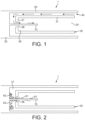
- Figure 1 illustrates a portion of a prior art aerosol-generating device that includes an extractor of the type disclosed, for example, in WO 2013/076098 .
- the device 1 includes a heater blade 10 mounted by and projecting outwardly from a heater support 20.
- the device 1 further includes an extractor 30 that is slideably mounted such that it can move relative to the heater 10.
- the extractor 30 has a cavity 35 for receiving an aerosol-generating article.
- a proximal end of the cavity is open to allow an aerosol-generating article to be received.
- a distal end of the cavity 36 terminates in an end-wall 37 which acts to support a distal end of an aerosol-generating article received in the cavity 35.
- An aperture 38 defined through the thickness of the end-wall 37 of the extractor 30 allows the heater blade 10 to penetrate into the cavity 35.
- the debris and residue is highly adherent and resists light mechanical brushing. A more vigorous mechanical brushing is undesirable as it is easy to damage the heater blade 10.
- the debris 62 mainly builds up at the base of the heater blade 10 and, as this portion of the heater blade tends to be unheated or heated to a lower temperature than a working end of the heater blade, it is difficult to remove using pyrolysis. That is, it is difficult to remove debris and residue building up around the base of a heater blade by heating the heater blade to a high temperature in order to pyrolyse the residue and debris, because this portion of the heater blade needs to be maintained at a low temperature.
- the portion of the device that collects the debris is the portion of the aerosol-generating device that includes electronics. It is, therefore, difficult to wash this portion of the device without risking damage to the electronics.
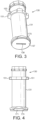
- Figures 3 and 4 are a perspective illustration and a side illustration respectively of an extractor 130 for an aerosol-generating device.
- the extractor is a substantially tubular structure having a tubular side wall 131 defining a cavity (not shown) for receiving an aerosol-generating article, a distal end of the cavity terminating in an end-wall 137.
- a slot-shaped aperture 138 is defined through the end-wall 137 to allow a heater blade to penetrate the cavity of the extractor 130.
- the outer surface of the end-wall 137 is designed to fit flush against a corresponding surface of a heater support without leaving a gap.
- the extractor 130 includes an orientation ring 153 comprising a plurality of orientation lugs 151. The orientation lugs engage with corresponding grooves on a portion of the aerosol-generating device in order to appropriately orient the extractor 130 and the aperture 138 so that it engages with a heater blade.
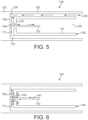
- the aerosol-generating device 100 of Figure 5 is a schematic cross-sectional diagram.
- the device 100 includes a heater blade 110 mounted by and extending from a heater support 120.
- the device 100 further includes an extractor 130 of the type illustrated in Figures 3 and 4 .
- the extractor defines a cavity 135 for receiving an aerosol-generating article.
- the cavity is defined by side walls 131 and by an end-wall 137.
- An aperture 138 is defined through the end-wall 137 to allow passage of the heater 110 into the cavity 135.
- An outer face 139 of the end-wall 137 is planar and abuts a planar face 129 of the heater support 120. There is substantially no gap between the outer face 139 or the end-wall 137 and the face 129 of the heater support 120.
- the air-flow channel 171 is defined as a radially extending channel within the thickness of the end-wall 137.
- the inlet 170 of the air-flow channel 171 is defined in side wall 131 of the extractor.
- the air-flow channel 171 extends radially inwards towards the heater blade aperture.
- the air-flow channel 171 joins the aperture 138, thereby allowing air flow into the cavity 135 of the extractor 130.
- An air-flow path is shown by arrows in Figure 5 .
- the arrows show that an air-flow path 140 is defined between an outer wall 150 of the device 100 and side walls 131 of the extractor.
- Figure 7 illustrates the aerosol-generating device 100 of Figures 5 and 6 engaged with an aerosol-generating article 190.
- the aerosol-generating article 190 has a proximal, or mouth, end 191 on which a user may draw during use to obtain an aerosol.
- the aerosol-generating article 190 further comprises an aerosol-forming substrate 192 located towards a distal end of the article 190.
- the aerosol-generating article 190 is shown received within the cavity 135 of the extractor 130.
- the extractor is in its first position, or operating position, in which the aerosol-generating article 190 is penetrated by the heater 110.
- the heater is actuated to heat the aerosol-generating article.
- the extractor 130 is moved to its second, extraction, position. In this position the end-wall 137 of the extractor engages with the aerosol-generating article and pulls the aerosol-generating article from the heater blade 110. The aerosol-generating article may then be removed from the cavity easily. Debris, such as fragments of tobacco are retained within the extractor.
- the build-up of debris and residue within the extractor may start to affect the air flow within the extractor.
- the entire extractor 130 is removed from the aerosol-generating device and is cleaned by washing with water.
- the aerosol-generating article 190 is preferably a smoking article and the aerosol-forming substrate is preferably a substrate comprising homogenised tobacco.
- the smoking article has an elongate cylindrical shape and comprises an aerosol-forming substrate, and a filter plug, arranged sequentially and in coaxial alignment.
- the aerosol-forming substrate and filter plug are overwrapped with an outer paper wrapper.
- Other components may be included in the smoking article.
- FIGS 9 and 10 illustrate an embodiment of an aerosol-generating device 200 according to the present invention engaged with an aerosol-generating article 190.
- the aerosol-generating device includes an extractor 230.
- the extractor has a cavity 235 defined by side walls 231 for receiving the aerosol-generating article 190.
- a distal end of the cavity 235 terminates in an end-wall 237.
- An aperture 238 is defined through the end-wall for allowing passage of a heater blade.
- An air-flow inlet 270 is defined through a side wall 231 of the extractor 230. In use, air passes into the cavity 235 through air inlets 270.
- Figure 10 shows the device 200 of Figure 9 with the extractor 230 moving towards its second, extraction, position.
Description
- The present specification relates to an elongated aerosol-generating device for use with an aerosol-generating article comprising an aerosol-forming substrate. The aerosol-generating article can be received by the aerosol-generating device. The device includes an extractor for assisting the removal of the aerosol-generating article after consumption.
- A number of prior art documents disclose aerosol-generating devices that include, for example, heated smoking systems and electrically heated smoking systems. One advantage of these systems is that they significantly reduce sidestream smoke, while permitting the smoker to selectively suspend and reinitiate smoking. An example of a heated smoking system is disclosed in
U.S. Patent No. 5,144,962 , which includes in one embodiment a flavour-generating medium in contact with a heater. When the medium is exhausted, both it and the heater are replaced. An aerosol-generating device where a substrate can be replaced without the need to remove the heating element is desirable. -
WO 2013/102609 provides a disclosure of an aerosol-generating device having a heating element and a substrate holder portion for removing the smoking article after use, and the substrate holder comprises a cavity. -
WO2013/076098 provides a disclosure of an aerosol-generating device having a heater that is insertable into the aerosol-forming substrate of an aerosol-generating article and an extractor for facilitating the removal of the aerosol-generating article after use. Although the extractor ofWO2013/076098 is successful in maintaining integrity of an aerosol-generating article during removal, a problem has been identified. Loose fragments of aerosol-forming substrate and other debris derived from the aerosol-generating article tend to fall out of the extractor and accumulate in the aerosol-generating device. This may adversely affect the air-flow path that allows air to pass over the aerosol-forming substrate as it is difficult to clean the region of the device around the base of the heater efficiently. -
WO 2015/197627 provides a disclosure of an aerosol-generating device having a heater, and a guide portion which facilitates proper alignment of the heater in the body portion of the aerosol-generating device with the cavity in the cartridge of the aerosol-generating article during insertion of the cartridge into the body portion of the aerosol-generating device. - The present disclosure relates to an elongated aerosol-generating device capable of receiving an aerosol-generating article. The aerosol-generating device comprises a heater for heating the aerosol-generating article and an extractor for extracting an aerosol-forming article received in the aerosol-generating device. The heater extends longitudinally with respect to the elongated aerosol-generating device and is configured for penetrating an internal portion of the aerosol-generating article. The extractor is slidable within the aerosol-generating device, the extractor is slidable between a first position and a second position, the first position being an operating position defined by the heater being in contact with the aerosol-generating article, and the second position being an extraction position defined by the heater being separated from the aerosol-generating article. The extractor is capable of being removed from the aerosol-generating device for cleaning. The extractor comprises a cavity for receiving the aerosol-generating article. A first aperture is defined through an end-wall of the cavity for allowing the heater to penetrate the cavity when the extractor is moved between the second position and the first position. The extractor further defines an air-flow channel for allowing air flow into the cavity, an inlet of the air-flow channel being positioned at a point that is radially-outward of the first aperture. The inlet of the air-flow channel is defined in a side-wall of the cavity.
- In use, a user draws on an end of an aerosol-generating article received in the cavity. The aerosol-generating article comprises an aerosol-forming substrate that is heated by the heater. Air is drawn into the cavity through the air-flow channel and flows over the aerosol-forming substrate. Volatile components evolved from the heated aerosol-forming substrate are entrained into the air-flow and condense, forming an inhalable aerosol.
- In the aerosol-generating device disclosed in
WO2013/076098 air flows into the extractor cavity through the same aperture that allows the heater to penetrate into the cavity. An air flow path within the device allows air to reach an underside of the end-wall of the cavity and from there the air flows through the aperture, along side the heater and into the cavity. The need for air to flow through the cavity means that the aperture needs to be dimensioned such that there is sufficient clearance to allow the desired air flow once the heater is in position. After a number of uses, debris from successive aerosol-generating articles falls through the aperture and collects around the base of the heater and in the air flow path of the device. This debris may be adherent and may build up to obstruct or block the air-flow path through the device, thereby inhibiting the consumer's experience. It is difficult to clean debris that builds up in the device outside the cavity of the extractor. - In the present disclosure the first aperture, for accommodating the heater, is not the air inlet position into the extractor. The air inlet is spaced radially outside the first aperture. The air inlets are defined in a side wall of the cavity.
- Preferably the air-flow path through the extractor involves air flowing in a radial direction towards the heater for at least a portion of the air-flow path. Debris falling through the first aperture will, therefore, not block the air-flow path. It may be that debris blocks the air-flow path internally, but it is preferred that the extractor can be removed from the device to allow any such debris to be easily removed, for example by washing with water.
- Preferably, the first aperture is dimensioned to allow a clearance of 0.5 mm or less to the heater. The clearance of 0.5 mm or less allows a portion of the heater to pass through the aperture, so as to enter the cavity and penetrate an aerosol-forming article within the cavity, but helps to prevent the egress of particles of aerosol-forming substrate or other debris from the cavity. It may be preferable that the first aperture has dimensions identical to cross-sectional dimensions of the heater so that the heater scrapes the aperture when passing into and out of the cavity. This may further prevent egress of debris from the cavity through the first aperture.
- The air-flow path from the air-flow channel inlet may join with the first aperture.
- The extractor is preferably designed such that particles of aerosol-forming substrate, or other debris that may derive from an aerosol-generating article, is trapped or retained within the extractor portion of the aerosol-generating device when the aerosol-generating article has been extracted. The extractor may then be removed from the device and cleaned on a regular basis to maintain the consumer experience.
- In preferred embodiments, an outer face of the end-wall may abut a portion or face of the aerosol-generating device when the extractor is in the first position, such that debris from the aerosol-generating article cannot build up in the aerosol-generating device. That is, there is no gap for debris to fall into between the extractor and the remaining parts of the aerosol-generating device. This may help ensure that any debris is retained within the extractor.
- The extractor may comprise a first air-flow channel and a second air-flow channel, inlets to the first and second air-flow channels being located on opposite sides of the extractor. There may be more than two air-flow channels.
- Air may flow into the cavity via outlets from the air-flow channels that are defined in an internal surface of the end-wall. Air may flow into the cavity via outlets from the air-flow channels that join the first aperture, such that air flow into the cavity is directed over or near the heater.
- The disclosure may also relate to an aerosol-generating system comprising an elongated aerosol-generating device as described above and an aerosol-generating article, the aerosol-generating article comprising an aerosol-forming substrate for evolving an inhalable aerosol when heated by the heater. The aerosol-forming substrate may comprise a sheet of homogenised tobacco.
- When an aerosol-forming article is received within the cavity of the extractor, the extractor may be capable of positioning the aerosol-forming substrate in contact with the heater.
- As used herein, the term 'positioning' relates to the movement of the aerosol-generating article or the aerosol-forming substrate relative to the heater of the aerosol-generating device. Thus, the extractor can be said to be capable of moving the aerosol-forming substrate relative to the heater in order to facilitate the removal of the aerosol-forming substrate from the aerosol-generating device.
- As used herein, an 'aerosol-generating device' relates to a device that interacts with an aerosol-forming substrate of an aerosol-generating article to generate an aerosol. The aerosol-forming substrate is part of an aerosol-generating article, for example part of a smoking article. An aerosol-generating device may comprise one or more components used to supply energy from a power supply to an aerosol-forming substrate to generate an aerosol. For example, an aerosol-generating device may be a heated aerosol-generating device. An aerosol-generating device may be an electrically heated aerosol-generating device or a gas-heated aerosol-generating device. An aerosol-generating device may be a smoking device that interacts with an aerosol-forming substrate of an aerosol-generating article to generate an aerosol that is directly inhalable into a user's lungs thorough the user's mouth. An aerosol-generating device may be a holder for an aerosol-generating article.
- As used herein, the term 'aerosol-forming substrate' relates to a substrate capable of releasing volatile compounds that can form an aerosol. Such volatile compounds may be released by heating the aerosol-forming substrate. An aerosol-forming substrate may conveniently be part of an aerosol-generating article or smoking article.
- As used herein, the terms 'aerosol-generating article' and 'smoking article' refer to an article comprising an aerosol-forming substrate that is capable of releasing volatile compounds that can form an aerosol. For example, an aerosol-generating article may be a smoking article that generates an aerosol that is directly inhalable into a user's lungs through the user's mouth. An aerosol-generating article may be disposable. The term 'smoking article' is generally used hereafter.
- Preferably a smoking article is a heated smoking article, which is a smoking article comprising an aerosol-forming substrate that is intended to be heated rather than combusted in order to release volatile compounds that can form an aerosol. The aerosol formed by heating the aerosol-forming substrate may contain fewer known harmful constituents than would be produced by combustion or pyrolytic degradation of the aerosol-forming substrate. A smoking article may be, or may comprise, a tobacco stick.
- In one embodiment, the extractor positions the smoking article comprising an aerosol-forming substrate in a first position and a second position, the first position being an operating position defined by the heater being in contact with the aerosol-forming substrate, and the second position being an extraction position defined by the aerosol-forming substrate being separated from the heater. Thus, the extractor may be movably coupled to an aerosol-generating device, and may be movable between a first position in which the aerosol-forming substrate is in contact with a heater of the aerosol-generating device, and a second position in which the aerosol-forming substrate is separated from the heater. Preferably the extractor remains coupled to the aerosol-generating device when in the first position, the second position and any intermediate point between the first position and second position. The extractor may be removably coupleable to the aerosol-generating device, in which case when the extractor is removed from the device it is neither in the first position nor the second position.
- The extractor is slidable between the first position and the second position.
- The first position of the extractor is an operating position in which the heater can heat the aerosol-forming substrate of the smoking article to form the aerosol. As known to those of ordinary skill in the art, an aerosol is a suspension of solid particles or liquid droplets or both solid particles and liquid droplets in a gas, such as air. The second position of the extractor is an extraction position which facilitates removal of the smoking article from the aerosol-generating device. The upstream and downstream ends of the aerosol-generating article are defined with respect to the airflow when the user takes a puff. Typically, incoming air enters the aerosol-generating article at the upstream end, combines with the aerosol, and carries the aerosol in the airflow towards the user's mouth at the downstream end.
- The extractor allows the integrity of the aerosol-forming substrate to be substantially maintained as the smoking article is removed from the aerosol-generating device.
- The aerosol-generating device may further comprise a stopper for preventing the extractor from sliding out of the aerosol-generating device when the extractor is moved to the second position. The stopper may be arranged to cooperate with stopper receiving means, for example an indent or depression for receiving the stopper. The stopper may be provided on the extractor. The stopper receiving means may be provided on another part of the aerosol-generating device.
- The aerosol-generating device may further comprise a guide pin for guiding the extractor as the extractor is moved between the first and second positions. The guide pin substantially prevents the extractor from rotating relative to the aerosol-generating device. The guide pin may be arranged to cooperate with a slot or groove. The guide pin, for example, may be provided on the extractor. The slot or groove may be provided in another part of the aerosol-generating device.
- The extractor may comprise insulating material, for providing insulation from the heat of the heater.
- The aerosol-generating device may be an electrically heated smoking system comprising an electric heater. In other embodiments the aerosol-generating device may be a heater smoking system comprising a gas-burner, or some source of heat other than electricity. The term "electric heater" refers to one or more electric heating elements. The electric heater may comprise an internal electric heating element for at least partially inserting into the aerosol-forming substrate of the smoking article. An "internal heating element" is one which is suitable for insertion into an aerosol-forming material. The invention is particularly advantageous when used in conjunction with an internal heating element since, in that case, there may be a tendency for the aerosol-forming substrate to stick to the heating element and therefore to break up as the aerosol-forming substrate is separated from the heating element.
- The electric heater may comprise a single heating element. Alternatively, the electric heater may comprise more than one heating element. The heating element or heating elements may be arranged appropriately so as to most effectively heat the aerosol-forming substrate.
- The electric heater may comprise an electrically resistive material. Suitable electrically resistive materials include but are not limited to: semiconductors such as doped ceramics, electrically "conductive" ceramics (such as, for example, molybdenum disilicide), carbon, graphite, metals, metal alloys and composite materials made of a ceramic material and a metallic material. Such composite materials may comprise doped or undoped ceramics. Examples of suitable doped ceramics include doped silicon carbides. Examples of suitable metals include titanium, zirconium, tantalum and metals from the platinum group. Examples of suitable metal alloys include stainless steel, nickel-, cobalt-, chromium-, aluminium- titanium- zirconium-, hafnium-, niobium-, molybdenum-, tantalum-, tungsten-, tin-, gallium-, manganese- and iron-containing alloys, and super-alloys based on nickel, iron, cobalt, stainless steel, Timetal® and iron-manganese-aluminium based alloys. In composite materials, the electrically resistive material may optionally be embedded in, encapsulated or coated with an insulating material or vice-versa, depending on the kinetics of energy transfer and the external physicochemical properties required. Alternatively, the electric heater may comprise an infra-red heating element, a photonic source, or an inductive heating element.
- The electric heater may take any suitable form. For example, the electric heater may take the form of a heating blade. Alternatively, the electric heater may take the form of a casing or substrate having different electro-conductive portions, or an electrically resistive metallic tube. Alternatively, one or more heating needles or rods that run through the centre of the aerosol-forming substrate may be as already described. Alternatively, the electric heater may be a disk (end) heater or a combination of a disk heater with heating needles or rods. Other alternatives include a heating wire or filament, for example a Ni-Cr (Nickel-Chromium), platinum, tungsten or alloy wire or a heating plate. Optionally, the heating element may be deposited in or on a rigid carrier material.
- The electric heater may comprise a heat sink, or heat reservoir comprising a material capable of absorbing and storing heat and subsequently releasing the heat over time to the aerosol-forming substrate. The heat sink may be formed of any suitable material, such as a suitable metal or ceramic material. In one embodiment, the material has a high heat capacity (sensible heat storage material), or is a material capable of absorbing and subsequently releasing heat via a reversible process, such as a high temperature phase change. Suitable sensible heat storage materials include silica gel, alumina, carbon, glass mat, glass fibre, minerals, a metal or alloy such as aluminium, silver or lead, and a cellulose material such as paper. Other suitable materials which release heat via a reversible phase change include paraffin, sodium acetate, naphthalene, wax, polyethylene oxide, a metal, metal salt, a mixture of eutectic salts or an alloy.
- The heat sink or heat reservoir may be arranged such that it is directly in contact with the aerosol-forming substrate and can transfer the stored heat directly to the substrate. Alternatively, the heat stored in the heat sink or heat reservoir may be transferred to the aerosol-forming substrate by means of a heat conductor, such as a metallic tube.
- The electric heater may heat the aerosol-forming substrate by means of conduction. The electric heater may be at least partially in contact with the substrate, or the carrier on which the substrate is deposited. Alternatively, the heat from the electric heater may be conducted to the substrate by means of a heat conductive element.
- Alternatively, the electric heater may transfer heat to the incoming ambient air that is drawn through the electrically heated smoking system during use, which in turn heats the aerosol-forming substrate by convection. The ambient air may be heated before passing through the aerosol-forming substrate.
- In one embodiment, electric energy is supplied to the electric heater until the heating element or elements of the electric heater reach a temperature of between approximately 250 °C and 440 °C. Any suitable temperature sensor and control circuitry may be used in order to control heating of the heating element or elements to reach the temperature of between approximately 250 °C and 440 °C. This is in contrast to conventional cigarettes in which the combustion of tobacco and cigarette wrapper may reach 800 °C.
- In one embodiment, the extractor comprises gripping means for gripping the smoking article when the smoking article is received in the extractor.
- The gripping means may ensure that the smoking article is correctly positioned so that the heater can heat the aerosol-forming substrate of the smoking article when the user puffs. In addition, the gripping means ensure that the smoking article does not fall out of the aerosol-generating device if the smoking system is oriented away from the vertical or away from the operating orientation. The gripping means may be arranged to grip the smoking article when a smoking article is received in the extractor, whether the extractor is in the first position or in the second position. Alternatively, the gripping means may be arranged to grip the smoking article when a smoking article is received in the extractor only when the sliding receptacle is in the first position.
- As mentioned above, removal of the smoking article from the aerosol-generating device may be achieved in two phases. In the first phase, the smoking article and extractor are moved, preferably by sliding, relative to components of the aerosol-generating device. In the second phase, the smoking article, now separate from the heater, can be removed from the extractor. A gripping means, if present, may be arranged to release the smoking article during the second phase.
- In one embodiment, the aerosol-generating device further comprises moving means for moving the extractor between the first and second positions.
- The moving means may comprise motorised moving means. The extractor may be moved between the first and second positions automatically when the user exerts a force on the smoking article to remove the smoking article from the aerosol-generating device. Alternatively, the extractor may be moved between the first and second positions automatically when the user operates a switch. Alternatively, no moving means may be provided and the extractor may be moved between the first and second positions manually by a user.
- During operation, the smoking article containing the aerosol-forming substrate may be completely contained within the aerosol-generating device. In that case, a user may puff on a mouthpiece of the aerosol-generating device. Alternatively, during operation the smoking article containing the aerosol-forming substrate may be partially contained within the aerosol-generating device. In that case, the user may puff directly on the smoking article.
- The smoking article may be substantially cylindrical in shape. The smoking article may be substantially elongate. The smoking article may have a length and a circumference substantially perpendicular to the length. The aerosol-forming substrate may be substantially cylindrical in shape. The aerosol-forming substrate may be substantially elongate. The aerosol-forming substrate may also have a length and a circumference substantially perpendicular to the length. The aerosol-forming substrate may be received in the extractor of the aerosol-generating device such that the length of the aerosol-forming substrate is substantially parallel to the airflow direction in the aerosol-generating device.
- The smoking article may have a total length between approximately 30 mm and approximately 100 mm. The smoking article may have an external diameter between approximately 5 mm and approximately 12 mm, for example about 7 mm. The smoking article may comprise a filter plug. The filter plug may be located at the downstream end of the smoking article. The filter plug may be a cellulose acetate filter plug. The filter plug is approximately 7 mm in length in one embodiment, but may have a length of between approximately 5 mm to approximately 10 mm.
- In one embodiment, the smoking article has a total length of approximately 45 mm. The smoking article may have an external diameter of approximately 7.2 mm. Further, the aerosol-forming substrate may have a length of approximately 10 mm. Alternatively, the aerosol-forming substrate may have a length of approximately 12 mm. Further, the diameter of the aerosol-forming substrate may be between approximately 5 mm and approximately 12 mm. The smoking article may comprise an outer paper wrapper. Further, the smoking article may comprise a separation between the aerosol-forming substrate and the filter plug. The separation may be approximately 18 mm, but may be in the range of approximately 5 mm to approximately 25 mm.
- The aerosol-forming substrate may be a solid aerosol-forming substrate. Alternatively, the aerosol-forming substrate may comprise both solid and liquid components. The aerosol-forming substrate may comprise a tobacco-containing material containing volatile tobacco flavour compounds which are released from the substrate upon heating. Alternatively, the aerosol-forming substrate may comprise a non-tobacco material. The aerosol-forming substrate may further comprise an aerosol former. Examples of suitable aerosol formers are glycerine and propylene glycol.
- If the aerosol-forming substrate is a solid aerosol-forming substrate, the solid aerosol-forming substrate may comprise, for example, one or more of: powder, granules, pellets, shreds, spaghettis, strips or sheets containing one or more of: herb leaf, tobacco leaf, fragments of tobacco ribs, reconstituted tobacco, homogenised tobacco, extruded tobacco and expanded tobacco. The solid aerosol-forming substrate may be in loose form, or may be provided in a suitable container or cartridge. Optionally, the solid aerosol-forming substrate may contain additional tobacco or non-tobacco volatile flavour compounds, to be released upon heating of the substrate. The solid aerosol-forming substrate may also contain capsules that, for example, include the additional tobacco or non-tobacco volatile flavour compounds and such capsules may melt during heating of the solid aerosol-forming substrate.
- Optionally, the solid aerosol-forming substrate may be provided on or embedded in a thermally stable carrier. The carrier may take the form of powder, granules, pellets, shreds, spaghettis, strips or sheets. Alternatively, the carrier may be a tubular carrier having a thin layer of the solid substrate deposited on its inner surface, or on its outer surface, or on both its inner and outer surfaces. Such a tubular carrier may be formed of, for example, a paper, or paper like material, a non-woven carbon fibre mat, a low mass open mesh metallic screen, or a perforated metallic foil or any other thermally stable polymer matrix.
- The solid aerosol-forming substrate may be deposited on the surface of the carrier in the form of, for example, a sheet, foam, gel or slurry. The solid aerosol-forming substrate may be deposited on the entire surface of the carrier, or alternatively, may be deposited in a pattern in order to provide a non-uniform flavour delivery during use.
- Although reference is made to solid aerosol-forming substrates above, it will be clear to one of ordinary skill in the art that other forms of aerosol-forming substrate may be included in other embodiments of the invention. For example, the aerosol-forming substrate may be a liquid aerosol-forming substrate. If a liquid aerosol-forming substrate is provided, the aerosol-generating device preferably comprises means for retaining the liquid. For example, the liquid aerosol-forming substrate may be retained in a container. Alternatively or in addition, the liquid aerosol-forming substrate may be absorbed into a porous carrier material. The porous carrier material may be made from any suitable absorbent plug or body, for example, a foamed metal or plastics material, polypropylene, terylene, nylon fibres or ceramic. The liquid aerosol-forming substrate may be retained in the porous carrier material prior to use of the aerosol-generating device or alternatively, the liquid aerosol-forming substrate material may be released into the porous carrier material during, or immediately prior to use. For example, the liquid aerosol-forming substrate may be provided in a capsule. The shell of the capsule preferably melts upon heating and releases the liquid aerosol-forming substrate into the porous carrier material. The capsule may optionally contain a solid in combination with the liquid.
- Alternatively, the carrier may be a non-woven fabric or fibre bundle into which tobacco components have been incorporated. The non-woven fabric or fibre bundle may comprise, for example, carbon fibres, natural cellulose fibres, or cellulose derivative fibres.
- Where the aerosol-generating device is an electrically heated smoking system, the electrically heated smoking system may further comprise a power supply for supplying power to the electric heater. The power supply may be any suitable power supply, for example a DC voltage source. In one embodiment, the power supply is a Lithium-ion battery. Alternatively, the power supply may be a Nickel-metal hydride battery, a Nickel cadmium battery, or a Lithium based battery, for example a Lithium-Cobalt, a Lithium-Iron-Phosphate or a Lithium-Polymer battery.
- The electrically heated smoking system may further comprise electronic circuitry arranged to be connected to the power supply and the electric heater. If more than one heating element is provided, the electronic circuitry may provide for the heating elements to be independently controllable. The electronic circuitry may be programmable.
- In one embodiment, the aerosol-generating device further comprises a sensor to detect air flow indicative of a user taking a puff which enables puff based activation of the electric heater or an improved energy management of the electric heater. The sensor may be any of: a mechanical device, an electro-mechanical device, an optical device, an opto-mechanical device and a micro electro-mechanical systems (MEMS) based sensor. In that embodiment, the sensor may be connected to the power supply and the system is arranged to activate the electric heater when the sensor senses a user taking a puff. In an alternative embodiment, the system further comprises a manually operable switch, for a user to initiate a puff or to enable a long-lasting smoking experience.
- Specific embodiments will now be described, by way of example only, with reference to the accompanying drawings, in which:
-
Figure 1 is a schematic cross-sectional diagram of a portion of a prior art aerosol-generating device showing, in particular, a heater, an extractor, and an air-flow path into the device; -
Figure 2 is a schematic diagram of the prior art aerosol-generating device as illustrated inFigure 1 , showing the positions that tobacco debris and residues typically build up within the device; -
Figure 3 is a perspective view of an extractor for use in an aerosol-generating device not falling under the scope of the appended claims; -
Figure 4 is a side view of the extractor ofFigure 3 ; -
Figure 5 is a schematic cross-sectional diagram of a portion of an aerosol-generating device not falling under the scope of the appended claims, showing in particular a heater, an extractor, and an air-flow path into the device; -
Figure 6 is a schematic diagram of the aerosol-generating device shown inFigure 5 , showing the positions that tobacco debris and residues typically build up within the device; -
Figure 7 is a schematic diagram showing the aerosol-generating device ofFigure 5 when engaged with an aerosol-generating article; -
Figure 8 is a schematic diagram illustrating the aerosol-generating device and aerosol-generating article ofFigure 7 with its extractor arranged in an extraction position; -
Figure 9 is a schematic cross-sectional diagram showing a portion of an aerosol-generating device according to one embodiment of the invention, the aerosol-generating device being engaged with an aerosol-generating article in an operating position; and -
Figure 10 is a schematic diagram of the aerosol-generating device and aerosol-generating article ofFigure 9 with its extractor in an extraction position. -
Figure 1 illustrates a portion of a prior art aerosol-generating device that includes an extractor of the type disclosed, for example, inWO 2013/076098 . Thedevice 1 includes aheater blade 10 mounted by and projecting outwardly from aheater support 20. Thedevice 1 further includes anextractor 30 that is slideably mounted such that it can move relative to theheater 10. Theextractor 30 has acavity 35 for receiving an aerosol-generating article. A proximal end of the cavity is open to allow an aerosol-generating article to be received. A distal end of thecavity 36 terminates in an end-wall 37 which acts to support a distal end of an aerosol-generating article received in thecavity 35. Anaperture 38 defined through the thickness of the end-wall 37 of theextractor 30 allows theheater blade 10 to penetrate into thecavity 35. -
Figure 1 illustrates the extractor in a first, or operating, position relative to the heater blade. In this position an aerosol-generating article received in thecavity 35 can be penetrated by theheater blade 10, thereby allowing theheater blade 10 to heat an aerosol-forming substrate of the aerosol-generating article. An air-flow path 40 is defined by channels extending between external walls of the aerosol-generatingdevice 50 andside walls 31 of the extractor. The arrows onFigure 1 illustrate the air-flow path as it passes along a channel betweenside walls 50 of the device andside walls 31 of the extractor before changing direction to flow between theheater support 20 and the distal end-wall 37 of the extractor, and then finally changing direction again to flow through theaperture 38 of the end-wall and into thecavity 35. This air flow passes in proximity to the heater and the air may therefore be heated and contribute to the formation of an aerosol. - The aerosol-generating articles are preferably smoking articles comprising tobacco. As successive aerosol-generating articles are consumed, fragments of aerosol-forming substrate and other debris and residue derived from the aerosol-forming substrate adhere to the heater blade and deposit thereon. Some of this debris and residue passes through the
aperture 38 at the distal end-wall 37 of the extractor and collects in agap 21 defined between theheater support 20 and the distal end-wall 37 of the extractor. This gap exists to allow air flow to theaperture 38 and consequently into the cavity. - Tests have been carried out to determine the level of substrate-derived debris and residue collected in the device with repeated usage.
Figure 2 illustrates a typical build up of such residue as occurs after about forty aerosol-generating articles have been consumed using the device. As can be seen in the schematic illustration ofFigure 2 , some debris andresidue 61 adheres to theheater blade 10, while other debris andresidue 62 accumulates in thegap 21 between the heater support and the extractor and within theaperture 38 defined into the extractor. In addition to contributing to the formation of undesirable aerosol products and odours, this residue and debris also affects the air flow into the device and, therefore, affects the formation of aerosol over time. As the debris andresidue heater blade 10. Thedebris 62 mainly builds up at the base of theheater blade 10 and, as this portion of the heater blade tends to be unheated or heated to a lower temperature than a working end of the heater blade, it is difficult to remove using pyrolysis. That is, it is difficult to remove debris and residue building up around the base of a heater blade by heating the heater blade to a high temperature in order to pyrolyse the residue and debris, because this portion of the heater blade needs to be maintained at a low temperature. Furthermore, the portion of the device that collects the debris is the portion of the aerosol-generating device that includes electronics. It is, therefore, difficult to wash this portion of the device without risking damage to the electronics. -
Figures 3 and 4 are a perspective illustration and a side illustration respectively of anextractor 130 for an aerosol-generating device. The extractor is a substantially tubular structure having atubular side wall 131 defining a cavity (not shown) for receiving an aerosol-generating article, a distal end of the cavity terminating in an end-wall 137. A slot-shapedaperture 138 is defined through the end-wall 137 to allow a heater blade to penetrate the cavity of theextractor 130. The outer surface of the end-wall 137 is designed to fit flush against a corresponding surface of a heater support without leaving a gap. Theextractor 130 includes anorientation ring 153 comprising a plurality of orientation lugs 151. The orientation lugs engage with corresponding grooves on a portion of the aerosol-generating device in order to appropriately orient theextractor 130 and theaperture 138 so that it engages with a heater blade. - An
air inlet 170 of an air-flow channel 171 is defined in aside wall 131 of theextractor 130. The air-flow channel 171 allows flow of air into the cavity. The arrangement of the air-flow channel 171 may be more clearly seen in the schematic diagrams ofFigures 5 and 6 . - The aerosol-generating
device 100 ofFigure 5 is a schematic cross-sectional diagram. Thedevice 100 includes aheater blade 110 mounted by and extending from aheater support 120. Thedevice 100 further includes anextractor 130 of the type illustrated inFigures 3 and 4 . The extractor defines acavity 135 for receiving an aerosol-generating article. The cavity is defined byside walls 131 and by an end-wall 137. Anaperture 138 is defined through the end-wall 137 to allow passage of theheater 110 into thecavity 135. Anouter face 139 of the end-wall 137 is planar and abuts aplanar face 129 of theheater support 120. There is substantially no gap between theouter face 139 or the end-wall 137 and theface 129 of theheater support 120. The air-flow channel 171 is defined as a radially extending channel within the thickness of the end-wall 137. Theinlet 170 of the air-flow channel 171 is defined inside wall 131 of the extractor. The air-flow channel 171 extends radially inwards towards the heater blade aperture. The air-flow channel 171 joins theaperture 138, thereby allowing air flow into thecavity 135 of theextractor 130. An air-flow path is shown by arrows inFigure 5 . The arrows show that an air-flow path 140 is defined between anouter wall 150 of thedevice 100 andside walls 131 of the extractor. The air flow path then deviates through the air-flow inlet 170 defined in aside wall 131 of the extractor, along an air-flow channel 171 defined within the end-wall 137 of the extractor, and into thecavity 135 of the extractor by means of theaperture 138 through which theheater 110 extends. -
Figure 6 shows a typical build-up of residue after use. Theresidue flow channel 171. As the majority of the debris andresidue 162 is retained within theextractor 130, it is easy to keep the device clean. For example, theextractor 130 may be removed from thedevice 100 and washed in running water to remove the debris and residue. This provides a convenient way of keeping the internal portions of the device clean. Furthermore, theaperture 138 through which theheater blade 110 extends may be dimensioned tightly, at least for a portion of the aperture, so that theheater blade 110 only just passes through the aperture. The aperture may be dimensioned such that the heater blade physically engages with the extractor on passing through theaperture 138. Thus, the aperture may be dimensioned such that the heater blade is scraped or wiped when the extractor is moved from its operating position to the extraction position, thereby cleaning the blade of debris and residue, the debris and residue remaining within the extractor. - Thus, by moving the air-
flow inlet 170 to a position that is radially external to theaperture 138 it is possible to configure the device such that debris and residue is substantially retained within the extractor. This keeps the heater blade and the device relatively clean. The debris and residue within the extractor may be easily and conveniently cleaned by washing the extractor. This example, not falling under the scope of the appended claims, makes it much simpler to maintain cleanliness of the device and, therefore improves the user experience of the device. - A method of operating the
device 100 will now be described with reference toFigures 7 and 8. Figure 7 illustrates the aerosol-generatingdevice 100 ofFigures 5 and 6 engaged with an aerosol-generatingarticle 190. The aerosol-generatingarticle 190 has a proximal, or mouth, end 191 on which a user may draw during use to obtain an aerosol. The aerosol-generatingarticle 190 further comprises an aerosol-formingsubstrate 192 located towards a distal end of thearticle 190. InFigure 7 the aerosol-generatingarticle 190 is shown received within thecavity 135 of theextractor 130. The extractor is in its first position, or operating position, in which the aerosol-generatingarticle 190 is penetrated by theheater 110. The heater is actuated to heat the aerosol-generating article. As the user draws on the proximal end of the aerosol-generating article, air is drawn into the aerosol-generating device and passes through the aerosol-formingsubstrate 192. Volatile components evolved from the aerosol-forming substrate are entrained within the air flow and condensed to form an inhalable aerosol. - Once the user has consumed the aerosol-generating
article 190, theextractor 130 is moved to its second, extraction, position. In this position the end-wall 137 of the extractor engages with the aerosol-generating article and pulls the aerosol-generating article from theheater blade 110. The aerosol-generating article may then be removed from the cavity easily. Debris, such as fragments of tobacco are retained within the extractor. - After the aerosol-generating device has been used for a number of times, the build-up of debris and residue within the extractor may start to affect the air flow within the extractor. At this point the
entire extractor 130 is removed from the aerosol-generating device and is cleaned by washing with water. - The aerosol-generating
article 190 is preferably a smoking article and the aerosol-forming substrate is preferably a substrate comprising homogenised tobacco. In a preferred embodiment, the smoking article has an elongate cylindrical shape and comprises an aerosol-forming substrate, and a filter plug, arranged sequentially and in coaxial alignment. The aerosol-forming substrate and filter plug are overwrapped with an outer paper wrapper. Other components may be included in the smoking article. -
Figures 9 and 10 illustrate an embodiment of an aerosol-generatingdevice 200 according to the present invention engaged with an aerosol-generatingarticle 190. As previously described the aerosol-generating device includes anextractor 230. The extractor has acavity 235 defined byside walls 231 for receiving the aerosol-generatingarticle 190. A distal end of thecavity 235 terminates in an end-wall 237. Anaperture 238 is defined through the end-wall for allowing passage of a heater blade. When theextractor 230 is in its operating position, anouter face 239 of the end-wall 237 abuts aface 229 of the heater blade support. There is substantially no gap between the extractor and the heater support. An air-flow inlet 270 is defined through aside wall 231 of theextractor 230. In use, air passes into thecavity 235 throughair inlets 270. - The difference between the embodiment of
Figure 9 and the embodiment ofFigure 5 is that air-flow inlets are defined through the side of the extractor and air flows directly through these inlets into the cavity. There may be grooves within the end-wall to channel the flow of air towards the heater blade, but there are no radially-extending channels defined within the end wall itself in this embodiment. -
Figure 10 shows thedevice 200 ofFigure 9 with theextractor 230 moving towards its second, extraction, position.
Claims (8)
- An elongated aerosol-generating device (200) capable of receiving an aerosol-generating article (190), comprising:a heater (110) for heating the aerosol-generating article, the heater extending longitudinally with respect to the elongated aerosol-generating device and being configured for penetrating an internal portion of the aerosol-generating article; andan extractor (230) for extracting the aerosol-generating article received in the aerosol-generating device, the extractor being slidable within the aerosol-generating device, the extractor being slidable between a first position and a second position, the first position being an operating position defined by the heater being in contact with the aerosol-generating article, and the second position being an extraction position defined by the heater being separated from the aerosol-generating article,wherein the extractor is capable of being removed from the aerosol-generating device for cleaning,wherein the extractor comprises a cavity ( 235) for receiving the aerosol-generating article, a first aperture (238) being defined through an end-wall (237) of the cavity for allowing the heater to penetrate the cavity when the extractor is moved between the second position and the first position, in which the extractor further defines an air-flow channel for allowing air flow into the cavity, an inlet ( 270) of the air-flow channel being positioned radially-outward of the first aperture;wherein the inlet of the air-flow channel is defined in a side-wall ( 231) of the cavity.
- An elongated aerosol-generating device ( 200) according to claim 1 in which the first aperture ( 238) is dimensioned to allow a clearance of 0.5 mm or less to the heater (110).
- An elongated aerosol-generating device ( 200) according to any preceding claim in which at least a portion of the air-flow channel extends radially within the end-wall (237).
- An elongated aerosol-generating device ( 200) according to any preceding claim in which the first aperture ( 238) and the air-flow channel are arranged so as to retain debris from the aerosol-generating article within the extractor ( 230) when the aerosol-generating article has been extracted.
- An elongated aerosol-generating device ( 200) according to any preceding claim in which an outer face (239) of the end-wall ( 237) abuts a portion of the aerosol-generating device when the extractor ( 230) is in the first position such that debris from the aerosol-generating article cannot build up in the aerosol-generating device.
- An elongated aerosol-generating device ( 200) according to any preceding claim comprising a first air-flow channel and a second air-flow channel, inlets to the first and second air-flow channels being located on opposite sides of the extractor ( 230).
- An aerosol-generating system comprising an elongated aerosol-generating device (200) according to any of claims 1 to 6 and an aerosol-generating article, the aerosol-generating article comprising an aerosol-forming substrate (192) for evolving an inhalable aerosol when heated by the heater (110).
- An aerosol-generating system according to claim 7 in which the aerosol-forming substrate (192) comprises a sheet of homogenised tobacco.
Priority Applications (1)
| Application Number | Priority Date | Filing Date | Title |
|---|---|---|---|
| EP23214564.9A EP4309527A3 (en) | 2015-02-06 | 2016-02-01 | Improved extractor for an aerosol-generating device |
Applications Claiming Priority (3)
| Application Number | Priority Date | Filing Date | Title |
|---|---|---|---|
| EP15154218 | 2015-02-06 | ||
| EP16702537.8A EP3253234B1 (en) | 2015-02-06 | 2016-02-01 | Improved extractor for an aerosol-generating device |
| PCT/EP2016/052088 WO2016124550A1 (en) | 2015-02-06 | 2016-02-01 | Improved extractor for an aerosol-generating device |
Related Parent Applications (2)
| Application Number | Title | Priority Date | Filing Date |
|---|---|---|---|
| EP16702537.8A Division EP3253234B1 (en) | 2015-02-06 | 2016-02-01 | Improved extractor for an aerosol-generating device |
| EP16702537.8A Division-Into EP3253234B1 (en) | 2015-02-06 | 2016-02-01 | Improved extractor for an aerosol-generating device |
Related Child Applications (2)
| Application Number | Title | Priority Date | Filing Date |
|---|---|---|---|
| EP23214564.9A Division-Into EP4309527A3 (en) | 2015-02-06 | 2016-02-01 | Improved extractor for an aerosol-generating device |
| EP23214564.9A Division EP4309527A3 (en) | 2015-02-06 | 2016-02-01 | Improved extractor for an aerosol-generating device |
Publications (3)
| Publication Number | Publication Date |
|---|---|
| EP3804540A1 EP3804540A1 (en) | 2021-04-14 |
| EP3804540B1 true EP3804540B1 (en) | 2024-01-10 |
| EP3804540C0 EP3804540C0 (en) | 2024-01-10 |
Family
ID=52462195
Family Applications (3)
| Application Number | Title | Priority Date | Filing Date |
|---|---|---|---|
| EP20207982.8A Active EP3804540B1 (en) | 2015-02-06 | 2016-02-01 | Improved extractor for an aerosol-generating device |
| EP16702537.8A Active EP3253234B1 (en) | 2015-02-06 | 2016-02-01 | Improved extractor for an aerosol-generating device |
| EP23214564.9A Pending EP4309527A3 (en) | 2015-02-06 | 2016-02-01 | Improved extractor for an aerosol-generating device |
Family Applications After (2)
| Application Number | Title | Priority Date | Filing Date |
|---|---|---|---|
| EP16702537.8A Active EP3253234B1 (en) | 2015-02-06 | 2016-02-01 | Improved extractor for an aerosol-generating device |
| EP23214564.9A Pending EP4309527A3 (en) | 2015-02-06 | 2016-02-01 | Improved extractor for an aerosol-generating device |
Country Status (10)
| Country | Link |
|---|---|
| US (2) | US11246342B2 (en) |
| EP (3) | EP3804540B1 (en) |
| JP (1) | JP6567680B2 (en) |
| KR (4) | KR101959503B1 (en) |
| CN (2) | CN111772243B (en) |
| CA (1) | CA2975654A1 (en) |
| IL (1) | IL252641B (en) |
| MX (1) | MX2017009957A (en) |
| RU (1) | RU2712348C2 (en) |
| WO (1) | WO2016124550A1 (en) |
Families Citing this family (112)
| Publication number | Priority date | Publication date | Assignee | Title |
|---|---|---|---|---|
| CN111772243B (en) * | 2015-02-06 | 2023-08-04 | 菲利普莫里斯生产公司 | Improved extractor for aerosol generating device |
| RU2749137C2 (en) | 2016-12-16 | 2021-06-04 | Кей Ти Энд Джи Корпорейшн | Device and method for aerosol generation |
| BR112019014992A2 (en) * | 2017-01-25 | 2020-04-07 | British American Tobacco Investments Ltd | heating element, article, system and apparatus for heating smokable material |
| US11771138B2 (en) | 2017-04-11 | 2023-10-03 | Kt&G Corporation | Aerosol generating device and method for providing smoking restriction function in aerosol generating device |
| WO2018190605A2 (en) * | 2017-04-11 | 2018-10-18 | 주식회사 케이티앤지 | Aerosol generating device |
| US11432593B2 (en) | 2017-04-11 | 2022-09-06 | Kt&G Corporation | Device for cleaning smoking member, and smoking member system |
| JP6942814B2 (en) | 2017-04-11 | 2021-09-29 | ケーティー・アンド・ジー・コーポレーション | Aerosol generation system that preheats the heater |
| KR20180114825A (en) | 2017-04-11 | 2018-10-19 | 주식회사 케이티앤지 | Method and apparatus for controlling electronic cigarettes |
| CN115024512A (en) | 2017-04-11 | 2022-09-09 | 韩国烟草人参公社 | Aerosol generating device |
| US11622582B2 (en) | 2017-04-11 | 2023-04-11 | Kt&G Corporation | Aerosol generating device and method for providing adaptive feedback through puff recognition |
| CN115777993A (en) | 2017-04-11 | 2023-03-14 | 韩国烟草人参公社 | Aerosol-generating system |
| JP6930802B2 (en) * | 2017-04-11 | 2021-09-01 | ケーティー・アンド・ジー・コーポレーション | Aerosol generator |
| JP6974822B2 (en) * | 2017-04-11 | 2021-12-01 | 暮らし創研株式会社 | Smoking equipment |
| KR102035313B1 (en) | 2017-05-26 | 2019-10-22 | 주식회사 케이티앤지 | Heater assembly and aerosol generating apparatus having the same |
| TW201902372A (en) | 2017-05-31 | 2019-01-16 | 瑞士商菲利浦莫里斯製品股份有限公司 | Heating member of aerosol generating device |
| CN110868874B (en) | 2017-08-09 | 2022-08-30 | 韩国烟草人参公社 | Electronic cigarette control method and device |
| WO2019031877A2 (en) | 2017-08-09 | 2019-02-14 | 주식회사 케이티앤지 | Aerosol generation device and control method for aerosol generation device |
| EP3664634B1 (en) | 2017-08-09 | 2021-11-17 | Philip Morris Products S.A. | Aerosol-generating device with detachably insertable heating compartment |
| US11647785B2 (en) | 2017-09-06 | 2023-05-16 | Kt&G Corporation | Aerosol generation device having structure for preventing liquid leakage |
| CN109645568A (en) * | 2017-10-10 | 2019-04-19 | 深圳瑞祥居科技发展有限公司 | A kind of smoking set |
| CN111148443A (en) * | 2017-10-24 | 2020-05-12 | 菲利普莫里斯生产公司 | Aerosol-generating device with retention mechanism |
| US10517332B2 (en) | 2017-10-31 | 2019-12-31 | Rai Strategic Holdings, Inc. | Induction heated aerosol delivery device |
| GB201719579D0 (en) * | 2017-11-24 | 2018-01-10 | British American Tobacco Investments Ltd | Removable member for an aerosol provision device |
| TW201928255A (en) | 2017-12-18 | 2019-07-16 | 瑞士商傑太日煙國際股份有限公司 | Heating assembly for a vapour generating device |
| KR20200102456A (en) | 2017-12-22 | 2020-08-31 | 필립모리스 프로덕츠 에스.에이. | Aerosol generator with easy-to-clean heating chamber |
| US20210112878A1 (en) * | 2017-12-22 | 2021-04-22 | Philip Morris Products S.A. | Aerosol-generating device with a removably-insertable residue collector |
| CN108451028A (en) * | 2018-01-22 | 2018-08-28 | 上海新型烟草制品研究院有限公司 | Release mechanism, aerosol generating device loosen method and smoking article |
| KR20190093024A (en) * | 2018-01-31 | 2019-08-08 | 주식회사 케이티앤지 | An apparatus for generating aerosols |
| JP7391855B2 (en) * | 2018-02-28 | 2023-12-05 | フィリップ・モーリス・プロダクツ・ソシエテ・アノニム | Cleaning tools for aerosol generators |
| CN108158043B (en) * | 2018-03-09 | 2023-07-11 | 广东中烟工业有限责任公司 | Cigarette electric heating device capable of realizing separation of cigarette and heating element and cleaning heating element by one-step method |
| TWI803585B (en) * | 2018-03-09 | 2023-06-01 | 瑞士商菲利浦莫里斯製品股份有限公司 | An aerosol-generating device and an aerosol-generating system |
| WO2019175102A1 (en) * | 2018-03-13 | 2019-09-19 | Philip Morris Products S.A. | Cleaning tool for heating element using suction effect |
| RU2744167C1 (en) * | 2018-03-13 | 2021-03-03 | Филип Моррис Продактс С.А. | Cleaning device with legs for a heating element |
| CN108618205A (en) * | 2018-03-23 | 2018-10-09 | 绿烟实业(深圳)有限公司 | Non-burning smoking set with extractor |
| KR102447360B1 (en) * | 2018-04-25 | 2022-09-26 | 주식회사 케이티앤지 | Aerosols generating apparatus |
| EP4133959B1 (en) * | 2018-04-26 | 2023-11-08 | Japan Tobacco Inc. | Heater assembly and container |
| CN110547507B (en) * | 2018-05-30 | 2020-11-24 | 深圳御烟实业有限公司 | Aerosol generating device |
| CN108618201A (en) * | 2018-06-04 | 2018-10-09 | 绿烟实业(深圳)有限公司 | Non-burning smoking set |
| KR102074934B1 (en) * | 2018-06-04 | 2020-02-07 | 주식회사 케이티앤지 | Apparatus for generating aerosols |
| JP7257424B2 (en) * | 2018-06-04 | 2023-04-13 | シグ-グリーン インダストリアル (シェンヂェン) カンパニー リミテッド | non-combustible smoking article |
| EP3801087B1 (en) * | 2018-06-07 | 2023-11-01 | Philip Morris Products S.A. | Aerosol-generating device |
| KR20210006399A (en) * | 2018-06-14 | 2021-01-18 | 필립모리스 프로덕츠 에스.에이. | Aerosol-generating device with heating coating |
| CN112203536A (en) * | 2018-06-14 | 2021-01-08 | 菲利普莫里斯生产公司 | Retractable heater for aerosol-generating device |
| EP3806677A1 (en) | 2018-06-15 | 2021-04-21 | Philip Morris Products S.A. | Dirt-repellent, heat-reflective coating for aerosol-generating device |
| US20210219615A1 (en) * | 2018-06-20 | 2021-07-22 | Jt International S.A. | Aerosol Generating Device With Removable Chamber |
| KR20210024460A (en) * | 2018-06-29 | 2021-03-05 | 필립모리스 프로덕츠 에스.에이. | Aerosol generation system with improved aerosol delivery |
| KR102330296B1 (en) * | 2018-07-05 | 2021-11-24 | 주식회사 케이티앤지 | Apparatus for generating aerosols |
| KR102389829B1 (en) * | 2018-07-09 | 2022-04-22 | 주식회사 케이티앤지 | Aerosol generating device having driver |
| US11930860B2 (en) * | 2018-07-17 | 2024-03-19 | Philip Morris Products S.A. | Cleaning tool for heating element with rotation prevention |
| GB201812498D0 (en) * | 2018-07-31 | 2018-09-12 | Nicoventures Holdings Ltd | Aerosol generation |
| WO2020025637A1 (en) | 2018-08-01 | 2020-02-06 | Philip Morris Products S.A. | Extractor for an aerosol-generating device |
| WO2020025746A1 (en) * | 2018-08-02 | 2020-02-06 | Philip Morris Products S.A. | System comprising aerosol-generating device and adapter element |
| CN108851248A (en) * | 2018-08-07 | 2018-11-23 | 上海新型烟草制品研究院有限公司 | A kind of aerosol generating device |
| CN110859326A (en) * | 2018-08-21 | 2020-03-06 | 湖南中烟工业有限责任公司 | Low-temperature smoking set convenient for smoke removal and smoke removal method |
| CN110870588A (en) * | 2018-08-21 | 2020-03-10 | 湖南中烟工业有限责任公司 | Heating element rotary separation type low-temperature smoking set and smoking withdrawing method |
| CA3112582A1 (en) * | 2018-09-14 | 2020-03-19 | Jt International Sa | Consumable retaining mechanism |
| US20210345672A1 (en) * | 2018-10-03 | 2021-11-11 | Jt International S.A. | Vapour Generating Device |
| CN111053290A (en) * | 2018-10-16 | 2020-04-24 | 上海新型烟草制品研究院有限公司 | Aerial fog generating device and aerial fog generating system |
| CN109077366A (en) * | 2018-10-25 | 2018-12-25 | 常州市派腾电子技术服务有限公司 | Electronic cigarette suction unit and electronic cigarette |
| JPWO2020084775A1 (en) * | 2018-10-26 | 2021-10-14 | 日本たばこ産業株式会社 | Control units, aerosol generators, methods and programs for controlling heaters, and smoking items |
| JP2022510920A (en) * | 2018-12-17 | 2022-01-28 | フィリップ・モーリス・プロダクツ・ソシエテ・アノニム | Extractor for aerosol generator |
| EP3911188B1 (en) * | 2019-01-15 | 2023-03-01 | Philip Morris Products S.A. | Aerosol-generating device with movable top cover |
| EP3692842A1 (en) * | 2019-02-07 | 2020-08-12 | Nerudia Ltd. | A substrate |
| US20220022537A1 (en) * | 2019-02-07 | 2022-01-27 | Nerudia Limited | Smoking substitute apparatus |
| EP3711586A1 (en) * | 2019-03-22 | 2020-09-23 | Nerudia Limited | Stopper for a smoking substitute device |
| EP3711525A1 (en) * | 2019-03-22 | 2020-09-23 | Nerudia Limited | Smoking substitute system |
| CN109846095A (en) * | 2019-04-02 | 2019-06-07 | 深圳市康柏特科技开发有限公司 | A kind of multi-functional separator of cigarette heater |
| JP6969031B2 (en) * | 2019-04-18 | 2021-11-24 | 日本たばこ産業株式会社 | Heat-not-burn tobacco |
| EP3957199A4 (en) * | 2019-04-18 | 2022-12-14 | Japan Tobacco Inc. | Heated tobacco product |
| KR102253047B1 (en) * | 2019-05-08 | 2021-05-17 | 주식회사 케이티앤지 | Aerosol generating device and system |
| KR102271275B1 (en) * | 2019-05-14 | 2021-06-30 | 주식회사 케이티앤지 | Aerosol generating device, Cleaning kit for Aerosol generating device and Aerosol generating system |
| KR102253049B1 (en) * | 2019-06-13 | 2021-05-17 | 주식회사 케이티앤지 | Aerosol generating device |
| CN110301676A (en) | 2019-06-27 | 2019-10-08 | 广东中烟工业有限责任公司 | A kind of heating for preventing pipe tobacco from falling is not burnt tobacco matrixes and its application |
| CN110279147A (en) * | 2019-06-28 | 2019-09-27 | 广东中烟工业有限责任公司 | A kind of cigarette heating device |
| CN111493367A (en) * | 2019-07-04 | 2020-08-07 | 青岛颐中科技有限公司 | Cigarette clamping device of low-temperature smoking set, low-temperature smoking set and low-temperature smoking set assembly |
| KR102480482B1 (en) * | 2019-07-05 | 2022-12-23 | 주식회사 케이티앤지 | Aerosol generating device |
| WO2021037655A1 (en) * | 2019-08-23 | 2021-03-04 | Philip Morris Products S.A. | Temperature detection in peripherally heated aerosol-generating device |
| US20220378099A1 (en) * | 2019-09-12 | 2022-12-01 | Jt International Sa | A Holder for a Heat-Not-Burn Aerosol-Generating Article |
| CN114286628A (en) * | 2019-09-20 | 2022-04-05 | 菲利普莫里斯生产公司 | Cleaning implement with additional cleaning element for aerosol-generating device |
| KR102317841B1 (en) * | 2019-10-11 | 2021-10-26 | 주식회사 케이티앤지 | Vaporizer and aerosol generating device comprising the same |
| KR102363396B1 (en) * | 2019-10-16 | 2022-02-15 | 주식회사 케이티앤지 | Aerosol generating device including extractor |
| KR102423896B1 (en) * | 2019-11-22 | 2022-07-21 | 주식회사 케이티앤지 | Aerosol generating device |
| WO2021130189A1 (en) * | 2019-12-23 | 2021-07-01 | Philip Morris Products S.A. | Aerosol-generating device having a ventilation chamber |
| CN114845577A (en) * | 2019-12-23 | 2022-08-02 | 菲利普莫里斯生产公司 | Aerosol-generating system with ventilation chamber |
| EP4096451A1 (en) * | 2020-01-28 | 2022-12-07 | Nerudia Limited | Smoking substitute device, cap removal device, and system |
| EP3858165A1 (en) * | 2020-01-28 | 2021-08-04 | Nerudia Limited | Smoking substitute device |
| CN212279897U (en) * | 2020-03-30 | 2021-01-05 | 深圳市合元科技有限公司 | Aerosol generator |
| GB202004704D0 (en) * | 2020-03-31 | 2020-05-13 | Nicoventures Trading Ltd | Delivery system |
| US11304452B2 (en) * | 2020-04-08 | 2022-04-19 | Shenzhen TopGreen Technology Co. Ltd. | Direct heating vaporizer |
| US20210345667A1 (en) * | 2020-05-08 | 2021-11-11 | R. J. Reynolds Tobacco Company | Aerosol delivery device |
| KR102535305B1 (en) | 2020-06-17 | 2023-05-22 | 주식회사 케이티앤지 | Aerosol generating device |
| KR102533743B1 (en) * | 2020-06-18 | 2023-05-17 | 주식회사 케이티앤지 | Aerosol generating apparatus |
| EP4176738A4 (en) | 2020-07-03 | 2024-03-20 | Japan Tobacco Inc | Heating device and heating system |
| CN111972712A (en) * | 2020-07-07 | 2020-11-24 | 深圳麦时科技有限公司 | Aerosol generating device |
| GB202016481D0 (en) * | 2020-10-16 | 2020-12-02 | Nicoventures Holdings Ltd | Aerosol provision device |
| GB202016478D0 (en) * | 2020-10-16 | 2020-12-02 | Nicoventures Trading Ltd | Aerosol provision device |
| GB202016480D0 (en) * | 2020-10-16 | 2020-12-02 | Nicoventures Trading Ltd | Aerosol provision device |
| WO2022123756A1 (en) * | 2020-12-11 | 2022-06-16 | 日本たばこ産業株式会社 | Flavor aspirator |
| WO2022123769A1 (en) * | 2020-12-11 | 2022-06-16 | 日本たばこ産業株式会社 | Flavor inhaler |
| KR102589998B1 (en) * | 2021-01-29 | 2023-10-16 | 주식회사 케이티앤지 | Aerosol generating device |
| JPWO2022180726A1 (en) * | 2021-02-25 | 2022-09-01 | ||
| BR112023020634A2 (en) * | 2021-04-09 | 2023-12-05 | Philip Morris Products Sa | MOVEMENT BETWEEN CONSUMPTION POSITION AND STORAGE POSITION IN AN AEROSOL GENERATING DEVICE |
| CN114128924A (en) * | 2021-11-02 | 2022-03-04 | 深圳麦时科技有限公司 | Electronic atomization device and electronic atomization system |
| KR20230075702A (en) * | 2021-11-23 | 2023-05-31 | 주식회사 케이티앤지 | Device for generating aerosol |
| WO2023094960A1 (en) * | 2021-11-25 | 2023-06-01 | Philip Morris Products S.A. | Cleaning tool for aerosol-generating device |
| WO2023117911A1 (en) * | 2021-12-22 | 2023-06-29 | Nicoventures Trading Limited | Aerosol provision device |
| WO2023118003A1 (en) * | 2021-12-22 | 2023-06-29 | Nicoventures Trading Limited | Aerosol generating device |
| WO2023128487A1 (en) * | 2021-12-28 | 2023-07-06 | Kt&G Corporation | Extractor and aerosol-generating device including the same |
| CN217885102U (en) * | 2022-03-01 | 2022-11-25 | 索图电子(惠州)有限公司 | Bottom support for heating non-combustion smoking set and smoking set using same |
| WO2023187029A1 (en) * | 2022-03-31 | 2023-10-05 | Philip Morris Products S.A. | Aerosol-generating device for use with an aerosol-generating article |
| WO2023208963A1 (en) * | 2022-04-29 | 2023-11-02 | Nicoventures Trading Limited | Aerosol provision device |
| CN115226952A (en) * | 2022-05-16 | 2022-10-25 | 深圳麦时科技有限公司 | Aerosol generating device |
Family Cites Families (20)
| Publication number | Priority date | Publication date | Assignee | Title |
|---|---|---|---|---|
| US1527991A (en) * | 1922-07-26 | 1925-03-03 | Collins James F | Cigarette holder |
| US4461308A (en) * | 1981-06-12 | 1984-07-24 | Leslie N. Aikman | Tobacco smoke filters |
| JPS62119948A (en) | 1985-11-20 | 1987-06-01 | Hitachi Ltd | Semiconductor device |
| JPS62119948U (en) * | 1986-01-21 | 1987-07-30 | ||
| US4947874A (en) * | 1988-09-08 | 1990-08-14 | R. J. Reynolds Tobacco Company | Smoking articles utilizing electrical energy |
| US5144962A (en) | 1989-12-01 | 1992-09-08 | Philip Morris Incorporated | Flavor-delivery article |
| US5388594A (en) * | 1991-03-11 | 1995-02-14 | Philip Morris Incorporated | Electrical smoking system for delivering flavors and method for making same |
| US5240012A (en) | 1991-11-13 | 1993-08-31 | Philip Morris Incorporated | Carbon heat smoking article with reusable body |
| US5878752A (en) * | 1996-11-25 | 1999-03-09 | Philip Morris Incorporated | Method and apparatus for using, cleaning, and maintaining electrical heat sources and lighters useful in smoking systems and other apparatuses |
| US5954979A (en) * | 1997-10-16 | 1999-09-21 | Philip Morris Incorporated | Heater fixture of an electrical smoking system |
| JP3327826B2 (en) | 1997-12-05 | 2002-09-24 | 日本たばこ産業株式会社 | Flavor producing articles and flavor producing instruments |
| EP2319334A1 (en) | 2009-10-27 | 2011-05-11 | Philip Morris Products S.A. | A smoking system having a liquid storage portion |
| RS54959B1 (en) * | 2011-11-21 | 2016-11-30 | Philip Morris Products Sa | Ejector for an aerosol-generating device |
| RS54759B1 (en) * | 2011-12-30 | 2016-10-31 | Philip Morris Products Sa | Aerosol generating device with improved temperature distribution |
| SG11201403666XA (en) * | 2011-12-30 | 2014-07-30 | Philip Morris Products Sa | Smoking article with front-plug and aerosol-forming substrate and method |
| JP5963375B2 (en) | 2012-01-03 | 2016-08-03 | フィリップ・モーリス・プロダクツ・ソシエテ・アノニム | Aerosol generator and system with improved airflow |
| TWI608805B (en) * | 2012-12-28 | 2017-12-21 | 菲利浦莫里斯製品股份有限公司 | Heated aerosol-generating device and method for generating aerosol with consistent properties |
| EP2950674B1 (en) * | 2013-01-30 | 2023-08-30 | Philip Morris Products S.A. | Improved aerosol from tobacco |
| TWI669073B (en) * | 2014-06-24 | 2019-08-21 | 瑞士商菲利浦莫里斯製品股份有限公司 | Aerosol-generating system, aerosol-generating article, aerosol-generating device and method of controlling the reaction stoichiometry |
| CN111772243B (en) * | 2015-02-06 | 2023-08-04 | 菲利普莫里斯生产公司 | Improved extractor for aerosol generating device |
-
2016
- 2016-02-01 CN CN202010832993.4A patent/CN111772243B/en active Active
- 2016-02-01 EP EP20207982.8A patent/EP3804540B1/en active Active
- 2016-02-01 MX MX2017009957A patent/MX2017009957A/en unknown
- 2016-02-01 WO PCT/EP2016/052088 patent/WO2016124550A1/en active Application Filing
- 2016-02-01 CN CN201680007197.9A patent/CN107205494B/en active Active
- 2016-02-01 KR KR1020177019809A patent/KR101959503B1/en active IP Right Grant
- 2016-02-01 EP EP16702537.8A patent/EP3253234B1/en active Active
- 2016-02-01 RU RU2017130917A patent/RU2712348C2/en active
- 2016-02-01 KR KR1020227006845A patent/KR102575024B1/en active IP Right Grant
- 2016-02-01 KR KR1020197007243A patent/KR102370640B1/en active IP Right Grant
- 2016-02-01 EP EP23214564.9A patent/EP4309527A3/en active Pending
- 2016-02-01 KR KR1020237029802A patent/KR20230130171A/en not_active Application Discontinuation
- 2016-02-01 JP JP2017541607A patent/JP6567680B2/en active Active
- 2016-02-01 US US15/546,315 patent/US11246342B2/en active Active
- 2016-02-01 CA CA2975654A patent/CA2975654A1/en not_active Abandoned
-
2017
- 2017-06-04 IL IL252641A patent/IL252641B/en not_active IP Right Cessation
-
2022
- 2022-01-05 US US17/569,090 patent/US11910828B2/en active Active
Also Published As
| Publication number | Publication date |
|---|---|
| US20180049472A1 (en) | 2018-02-22 |
| RU2017130917A3 (en) | 2019-05-07 |
| CN111772243A (en) | 2020-10-16 |
| KR102575024B1 (en) | 2023-09-07 |
| CA2975654A1 (en) | 2016-08-11 |
| US11246342B2 (en) | 2022-02-15 |
| US11910828B2 (en) | 2024-02-27 |
| CN107205494B (en) | 2020-09-01 |
| KR102370640B1 (en) | 2022-03-04 |
| CN107205494A (en) | 2017-09-26 |
| IL252641B (en) | 2020-08-31 |
| EP4309527A3 (en) | 2024-03-27 |
| KR20230130171A (en) | 2023-09-11 |
| EP3804540C0 (en) | 2024-01-10 |
| EP3253234A1 (en) | 2017-12-13 |
| KR20220031943A (en) | 2022-03-14 |
| KR101959503B1 (en) | 2019-03-18 |
| KR20190029780A (en) | 2019-03-20 |
| CN111772243B (en) | 2023-08-04 |
| RU2017130917A (en) | 2019-03-12 |
| JP2018504134A (en) | 2018-02-15 |
| WO2016124550A1 (en) | 2016-08-11 |
| IL252641A0 (en) | 2017-07-31 |
| EP3253234B1 (en) | 2020-12-23 |
| EP4309527A2 (en) | 2024-01-24 |
| KR20170115492A (en) | 2017-10-17 |
| EP3804540A1 (en) | 2021-04-14 |
| RU2712348C2 (en) | 2020-01-28 |
| US20220125105A1 (en) | 2022-04-28 |
| MX2017009957A (en) | 2017-10-19 |
| JP6567680B2 (en) | 2019-08-28 |
Similar Documents
| Publication | Publication Date | Title |
|---|---|---|
| US11910828B2 (en) | Extractor for an aerosol-generating device | |
| CA3079706C (en) | Ejector for an aerosol-generating device | |
| EP2797445B1 (en) | Aerosol generating device with improved temperature distribution | |
| US20220202072A1 (en) | Aerosol-generating device with movably attached mouthpiece | |
| NZ624969B2 (en) | Ejector for an aerosol-generating device |
Legal Events
| Date | Code | Title | Description |
|---|---|---|---|
| PUAI | Public reference made under article 153(3) epc to a published international application that has entered the european phase |
Free format text: ORIGINAL CODE: 0009012 |
|
| STAA | Information on the status of an ep patent application or granted ep patent |
Free format text: STATUS: THE APPLICATION HAS BEEN PUBLISHED |
|
| AC | Divisional application: reference to earlier application |
Ref document number: 3253234 Country of ref document: EP Kind code of ref document: P |
|
| AK | Designated contracting states |
Kind code of ref document: A1 Designated state(s): AL AT BE BG CH CY CZ DE DK EE ES FI FR GB GR HR HU IE IS IT LI LT LU LV MC MK MT NL NO PL PT RO RS SE SI SK SM TR |
|
| STAA | Information on the status of an ep patent application or granted ep patent |
Free format text: STATUS: REQUEST FOR EXAMINATION WAS MADE |
|
| 17P | Request for examination filed |
Effective date: 20211012 |
|
| RBV | Designated contracting states (corrected) |
Designated state(s): AL AT BE BG CH CY CZ DE DK EE ES FI FR GB GR HR HU IE IS IT LI LT LU LV MC MK MT NL NO PL PT RO RS SE SI SK SM TR |
|
| GRAP | Despatch of communication of intention to grant a patent |
Free format text: ORIGINAL CODE: EPIDOSNIGR1 |
|
| STAA | Information on the status of an ep patent application or granted ep patent |
Free format text: STATUS: GRANT OF PATENT IS INTENDED |
|
| RIC1 | Information provided on ipc code assigned before grant |
Ipc: A24F 40/20 20200101ALN20230220BHEP Ipc: A24F 40/46 20200101ALI20230220BHEP Ipc: A24F 40/40 20200101AFI20230220BHEP |
|
| INTG | Intention to grant announced |
Effective date: 20230314 |
|
| P01 | Opt-out of the competence of the unified patent court (upc) registered |
Effective date: 20230529 |
|
| GRAJ | Information related to disapproval of communication of intention to grant by the applicant or resumption of examination proceedings by the epo deleted |
Free format text: ORIGINAL CODE: EPIDOSDIGR1 |
|
| STAA | Information on the status of an ep patent application or granted ep patent |
Free format text: STATUS: REQUEST FOR EXAMINATION WAS MADE |
|
| GRAP | Despatch of communication of intention to grant a patent |
Free format text: ORIGINAL CODE: EPIDOSNIGR1 |
|
| STAA | Information on the status of an ep patent application or granted ep patent |
Free format text: STATUS: GRANT OF PATENT IS INTENDED |
|
| INTC | Intention to grant announced (deleted) | ||
| RIC1 | Information provided on ipc code assigned before grant |
Ipc: A24F 40/20 20200101ALN20230720BHEP Ipc: A24F 40/46 20200101ALI20230720BHEP Ipc: A24F 40/40 20200101AFI20230720BHEP |
|
| INTG | Intention to grant announced |
Effective date: 20230808 |
|
| GRAS | Grant fee paid |
Free format text: ORIGINAL CODE: EPIDOSNIGR3 |
|
| GRAA | (expected) grant |
Free format text: ORIGINAL CODE: 0009210 |
|
| STAA | Information on the status of an ep patent application or granted ep patent |
Free format text: STATUS: THE PATENT HAS BEEN GRANTED |
|
| AC | Divisional application: reference to earlier application |
Ref document number: 3253234 Country of ref document: EP Kind code of ref document: P |
|
| AK | Designated contracting states |
Kind code of ref document: B1 Designated state(s): AL AT BE BG CH CY CZ DE DK EE ES FI FR GB GR HR HU IE IS IT LI LT LU LV MC MK MT NL NO PL PT RO RS SE SI SK SM TR |
|
| REG | Reference to a national code |
Ref country code: GB Ref legal event code: FG4D |
|
| REG | Reference to a national code |
Ref country code: CH Ref legal event code: EP |
|
| REG | Reference to a national code |
Ref country code: DE Ref legal event code: R096 Ref document number: 602016085329 Country of ref document: DE |
|
| REG | Reference to a national code |
Ref country code: IE Ref legal event code: FG4D |
|
| U01 | Request for unitary effect filed |
Effective date: 20240110 |
|
| U07 | Unitary effect registered |
Designated state(s): AT BE BG DE DK EE FI FR IT LT LU LV MT NL PT SE SI Effective date: 20240115 |
|
| P04 | Withdrawal of opt-out of the competence of the unified patent court (upc) registered |
Effective date: 20240110 |