JP7004006B2 - Hybrid vehicle control method and control device - Google Patents
Hybrid vehicle control method and control device Download PDFInfo
- Publication number
- JP7004006B2 JP7004006B2 JP2019558871A JP2019558871A JP7004006B2 JP 7004006 B2 JP7004006 B2 JP 7004006B2 JP 2019558871 A JP2019558871 A JP 2019558871A JP 2019558871 A JP2019558871 A JP 2019558871A JP 7004006 B2 JP7004006 B2 JP 7004006B2
- Authority
- JP
- Japan
- Prior art keywords
- rotation speed
- target
- engine rotation
- engine
- power consumption
- Prior art date
- Legal status (The legal status is an assumption and is not a legal conclusion. Google has not performed a legal analysis and makes no representation as to the accuracy of the status listed.)
- Active
Links
Images


Classifications
-
- B—PERFORMING OPERATIONS; TRANSPORTING
- B60—VEHICLES IN GENERAL
- B60K—ARRANGEMENT OR MOUNTING OF PROPULSION UNITS OR OF TRANSMISSIONS IN VEHICLES; ARRANGEMENT OR MOUNTING OF PLURAL DIVERSE PRIME-MOVERS IN VEHICLES; AUXILIARY DRIVES FOR VEHICLES; INSTRUMENTATION OR DASHBOARDS FOR VEHICLES; ARRANGEMENTS IN CONNECTION WITH COOLING, AIR INTAKE, GAS EXHAUST OR FUEL SUPPLY OF PROPULSION UNITS IN VEHICLES
- B60K6/00—Arrangement or mounting of plural diverse prime-movers for mutual or common propulsion, e.g. hybrid propulsion systems comprising electric motors and internal combustion engines ; Control systems therefor, i.e. systems controlling two or more prime movers, or controlling one of these prime movers and any of the transmission, drive or drive units Informative references: mechanical gearings with secondary electric drive F16H3/72; arrangements for handling mechanical energy structurally associated with the dynamo-electric machine H02K7/00; machines comprising structurally interrelated motor and generator parts H02K51/00; dynamo-electric machines not otherwise provided for in H02K see H02K99/00
- B60K6/20—Arrangement or mounting of plural diverse prime-movers for mutual or common propulsion, e.g. hybrid propulsion systems comprising electric motors and internal combustion engines ; Control systems therefor, i.e. systems controlling two or more prime movers, or controlling one of these prime movers and any of the transmission, drive or drive units Informative references: mechanical gearings with secondary electric drive F16H3/72; arrangements for handling mechanical energy structurally associated with the dynamo-electric machine H02K7/00; machines comprising structurally interrelated motor and generator parts H02K51/00; dynamo-electric machines not otherwise provided for in H02K see H02K99/00 the prime-movers consisting of electric motors and internal combustion engines, e.g. HEVs
- B60K6/42—Arrangement or mounting of plural diverse prime-movers for mutual or common propulsion, e.g. hybrid propulsion systems comprising electric motors and internal combustion engines ; Control systems therefor, i.e. systems controlling two or more prime movers, or controlling one of these prime movers and any of the transmission, drive or drive units Informative references: mechanical gearings with secondary electric drive F16H3/72; arrangements for handling mechanical energy structurally associated with the dynamo-electric machine H02K7/00; machines comprising structurally interrelated motor and generator parts H02K51/00; dynamo-electric machines not otherwise provided for in H02K see H02K99/00 the prime-movers consisting of electric motors and internal combustion engines, e.g. HEVs characterised by the architecture of the hybrid electric vehicle
- B60K6/46—Series type
-
- B—PERFORMING OPERATIONS; TRANSPORTING
- B60—VEHICLES IN GENERAL
- B60W—CONJOINT CONTROL OF VEHICLE SUB-UNITS OF DIFFERENT TYPE OR DIFFERENT FUNCTION; CONTROL SYSTEMS SPECIALLY ADAPTED FOR HYBRID VEHICLES; ROAD VEHICLE DRIVE CONTROL SYSTEMS FOR PURPOSES NOT RELATED TO THE CONTROL OF A PARTICULAR SUB-UNIT
- B60W20/00—Control systems specially adapted for hybrid vehicles
- B60W20/10—Controlling the power contribution of each of the prime movers to meet required power demand
- B60W20/13—Controlling the power contribution of each of the prime movers to meet required power demand in order to stay within battery power input or output limits; in order to prevent overcharging or battery depletion
-
- B—PERFORMING OPERATIONS; TRANSPORTING
- B60—VEHICLES IN GENERAL
- B60W—CONJOINT CONTROL OF VEHICLE SUB-UNITS OF DIFFERENT TYPE OR DIFFERENT FUNCTION; CONTROL SYSTEMS SPECIALLY ADAPTED FOR HYBRID VEHICLES; ROAD VEHICLE DRIVE CONTROL SYSTEMS FOR PURPOSES NOT RELATED TO THE CONTROL OF A PARTICULAR SUB-UNIT
- B60W10/00—Conjoint control of vehicle sub-units of different type or different function
- B60W10/04—Conjoint control of vehicle sub-units of different type or different function including control of propulsion units
- B60W10/06—Conjoint control of vehicle sub-units of different type or different function including control of propulsion units including control of combustion engines
-
- B—PERFORMING OPERATIONS; TRANSPORTING
- B60—VEHICLES IN GENERAL
- B60W—CONJOINT CONTROL OF VEHICLE SUB-UNITS OF DIFFERENT TYPE OR DIFFERENT FUNCTION; CONTROL SYSTEMS SPECIALLY ADAPTED FOR HYBRID VEHICLES; ROAD VEHICLE DRIVE CONTROL SYSTEMS FOR PURPOSES NOT RELATED TO THE CONTROL OF A PARTICULAR SUB-UNIT
- B60W10/00—Conjoint control of vehicle sub-units of different type or different function
- B60W10/04—Conjoint control of vehicle sub-units of different type or different function including control of propulsion units
- B60W10/08—Conjoint control of vehicle sub-units of different type or different function including control of propulsion units including control of electric propulsion units, e.g. motors or generators
-
- B—PERFORMING OPERATIONS; TRANSPORTING
- B60—VEHICLES IN GENERAL
- B60W—CONJOINT CONTROL OF VEHICLE SUB-UNITS OF DIFFERENT TYPE OR DIFFERENT FUNCTION; CONTROL SYSTEMS SPECIALLY ADAPTED FOR HYBRID VEHICLES; ROAD VEHICLE DRIVE CONTROL SYSTEMS FOR PURPOSES NOT RELATED TO THE CONTROL OF A PARTICULAR SUB-UNIT
- B60W20/00—Control systems specially adapted for hybrid vehicles
- B60W20/10—Controlling the power contribution of each of the prime movers to meet required power demand
- B60W20/13—Controlling the power contribution of each of the prime movers to meet required power demand in order to stay within battery power input or output limits; in order to prevent overcharging or battery depletion
- B60W20/14—Controlling the power contribution of each of the prime movers to meet required power demand in order to stay within battery power input or output limits; in order to prevent overcharging or battery depletion in conjunction with braking regeneration
-
- B—PERFORMING OPERATIONS; TRANSPORTING
- B60—VEHICLES IN GENERAL
- B60W—CONJOINT CONTROL OF VEHICLE SUB-UNITS OF DIFFERENT TYPE OR DIFFERENT FUNCTION; CONTROL SYSTEMS SPECIALLY ADAPTED FOR HYBRID VEHICLES; ROAD VEHICLE DRIVE CONTROL SYSTEMS FOR PURPOSES NOT RELATED TO THE CONTROL OF A PARTICULAR SUB-UNIT
- B60W30/00—Purposes of road vehicle drive control systems not related to the control of a particular sub-unit, e.g. of systems using conjoint control of vehicle sub-units, or advanced driver assistance systems for ensuring comfort, stability and safety or drive control systems for propelling or retarding the vehicle
- B60W30/18—Propelling the vehicle
- B60W30/18009—Propelling the vehicle related to particular drive situations
- B60W30/18109—Braking
- B60W30/18127—Regenerative braking
-
- B—PERFORMING OPERATIONS; TRANSPORTING
- B60—VEHICLES IN GENERAL
- B60W—CONJOINT CONTROL OF VEHICLE SUB-UNITS OF DIFFERENT TYPE OR DIFFERENT FUNCTION; CONTROL SYSTEMS SPECIALLY ADAPTED FOR HYBRID VEHICLES; ROAD VEHICLE DRIVE CONTROL SYSTEMS FOR PURPOSES NOT RELATED TO THE CONTROL OF A PARTICULAR SUB-UNIT
- B60W40/00—Estimation or calculation of non-directly measurable driving parameters for road vehicle drive control systems not related to the control of a particular sub unit, e.g. by using mathematical models
- B60W40/08—Estimation or calculation of non-directly measurable driving parameters for road vehicle drive control systems not related to the control of a particular sub unit, e.g. by using mathematical models related to drivers or passengers
-
- B—PERFORMING OPERATIONS; TRANSPORTING
- B60—VEHICLES IN GENERAL
- B60W—CONJOINT CONTROL OF VEHICLE SUB-UNITS OF DIFFERENT TYPE OR DIFFERENT FUNCTION; CONTROL SYSTEMS SPECIALLY ADAPTED FOR HYBRID VEHICLES; ROAD VEHICLE DRIVE CONTROL SYSTEMS FOR PURPOSES NOT RELATED TO THE CONTROL OF A PARTICULAR SUB-UNIT
- B60W40/00—Estimation or calculation of non-directly measurable driving parameters for road vehicle drive control systems not related to the control of a particular sub unit, e.g. by using mathematical models
- B60W40/10—Estimation or calculation of non-directly measurable driving parameters for road vehicle drive control systems not related to the control of a particular sub unit, e.g. by using mathematical models related to vehicle motion
- B60W40/105—Speed
-
- B—PERFORMING OPERATIONS; TRANSPORTING
- B60—VEHICLES IN GENERAL
- B60W—CONJOINT CONTROL OF VEHICLE SUB-UNITS OF DIFFERENT TYPE OR DIFFERENT FUNCTION; CONTROL SYSTEMS SPECIALLY ADAPTED FOR HYBRID VEHICLES; ROAD VEHICLE DRIVE CONTROL SYSTEMS FOR PURPOSES NOT RELATED TO THE CONTROL OF A PARTICULAR SUB-UNIT
- B60W2510/00—Input parameters relating to a particular sub-units
- B60W2510/06—Combustion engines, Gas turbines
- B60W2510/0638—Engine speed
- B60W2510/0652—Speed change rate
-
- B—PERFORMING OPERATIONS; TRANSPORTING
- B60—VEHICLES IN GENERAL
- B60W—CONJOINT CONTROL OF VEHICLE SUB-UNITS OF DIFFERENT TYPE OR DIFFERENT FUNCTION; CONTROL SYSTEMS SPECIALLY ADAPTED FOR HYBRID VEHICLES; ROAD VEHICLE DRIVE CONTROL SYSTEMS FOR PURPOSES NOT RELATED TO THE CONTROL OF A PARTICULAR SUB-UNIT
- B60W2520/00—Input parameters relating to overall vehicle dynamics
- B60W2520/10—Longitudinal speed
-
- B—PERFORMING OPERATIONS; TRANSPORTING
- B60—VEHICLES IN GENERAL
- B60W—CONJOINT CONTROL OF VEHICLE SUB-UNITS OF DIFFERENT TYPE OR DIFFERENT FUNCTION; CONTROL SYSTEMS SPECIALLY ADAPTED FOR HYBRID VEHICLES; ROAD VEHICLE DRIVE CONTROL SYSTEMS FOR PURPOSES NOT RELATED TO THE CONTROL OF A PARTICULAR SUB-UNIT
- B60W2540/00—Input parameters relating to occupants
- B60W2540/10—Accelerator pedal position
-
- B—PERFORMING OPERATIONS; TRANSPORTING
- B60—VEHICLES IN GENERAL
- B60W—CONJOINT CONTROL OF VEHICLE SUB-UNITS OF DIFFERENT TYPE OR DIFFERENT FUNCTION; CONTROL SYSTEMS SPECIALLY ADAPTED FOR HYBRID VEHICLES; ROAD VEHICLE DRIVE CONTROL SYSTEMS FOR PURPOSES NOT RELATED TO THE CONTROL OF A PARTICULAR SUB-UNIT
- B60W2710/00—Output or target parameters relating to a particular sub-units
- B60W2710/06—Combustion engines, Gas turbines
- B60W2710/0644—Engine speed
-
- B—PERFORMING OPERATIONS; TRANSPORTING
- B60—VEHICLES IN GENERAL
- B60Y—INDEXING SCHEME RELATING TO ASPECTS CROSS-CUTTING VEHICLE TECHNOLOGY
- B60Y2200/00—Type of vehicle
- B60Y2200/90—Vehicles comprising electric prime movers
- B60Y2200/92—Hybrid vehicles
-
- Y—GENERAL TAGGING OF NEW TECHNOLOGICAL DEVELOPMENTS; GENERAL TAGGING OF CROSS-SECTIONAL TECHNOLOGIES SPANNING OVER SEVERAL SECTIONS OF THE IPC; TECHNICAL SUBJECTS COVERED BY FORMER USPC CROSS-REFERENCE ART COLLECTIONS [XRACs] AND DIGESTS
- Y02—TECHNOLOGIES OR APPLICATIONS FOR MITIGATION OR ADAPTATION AGAINST CLIMATE CHANGE
- Y02T—CLIMATE CHANGE MITIGATION TECHNOLOGIES RELATED TO TRANSPORTATION
- Y02T10/00—Road transport of goods or passengers
- Y02T10/60—Other road transportation technologies with climate change mitigation effect
- Y02T10/62—Hybrid vehicles
Description
本発明は、ハイブリッド車両の制御方法及び制御装置に関するものである。 The present invention relates to a control method and a control device for a hybrid vehicle.
エンジンと、そのエンジンの回転速度を制御するための第1モータと、車両の慣性エネルギを回生して発電する第2モータと、これら第1モータおよび第2モータとの間で電力を授受する蓄電装置とを有するハイブリッド車の回生制御装置において、前記車両の慣性エネルギで前記第2モータを駆動して発電する回生制動時に前記蓄電装置が受け入れる電力が制限されることにより前記第2モータで発電した電力の一部を前記第1モータに供給して第1モータにより前記エンジンを強制的に回転させている回生状態を判断する判断手段と、前記回生状態の判断が成立している場合には、前記蓄電装置が受け入れる電力の制限の緩和量を前記回生状態の判断が成立していない場合の緩和量よりも小さくする充電制限手段とを備えていることを特徴とするハイブリッド車の回生制御装置が知られている(特許文献1)。 Storage of electricity between the engine, the first motor for controlling the rotation speed of the engine, the second motor that regenerates the inertial energy of the vehicle to generate power, and the first motor and the second motor. In the regenerative control device of a hybrid vehicle having the device, power is generated by the second motor by limiting the power received by the power storage device during regenerative braking in which the second motor is driven by the inertial energy of the vehicle to generate power. When a determination means for determining the regenerative state in which a part of the electric power is supplied to the first motor to forcibly rotate the engine by the first motor and the determination of the regenerative state are established, the determination is established. The regeneration control device for a hybrid vehicle is provided with a charge limiting means for reducing the relaxed amount of the power limit received by the power storage device to be smaller than the relaxed amount when the determination of the regenerative state is not established. It is known (Patent Document 1).
上記従来技術では、エネルギ回生を行う場合には、高車速時ほど蓄電装置が受け入れる電力の制限の緩和量を小さくして、エンジンの回転速度を制御している第1モータへの供給電力の変動を抑制して、エンジンの回転速度の上昇を抑制している。しかしながら、例えばアクセルを戻して減速する場合に、要求減速度が増加し、エンジンを発電機で駆動させることで回生電力を確保するときに、エンジンの回転速度の上昇が抑制されると、電力を十分に消費できず、ドライバの減速意図に対して十分な減速感を得ることができないため、ドライバへの違和感を与える。 In the above-mentioned conventional technique, when energy regeneration is performed, the amount of relaxation of the limitation of the electric power received by the power storage device is reduced as the vehicle speed is higher, and the fluctuation of the electric power supplied to the first motor controlling the rotation speed of the engine is changed. Is suppressed, and the increase in the rotation speed of the engine is suppressed. However, for example, when the accelerator is released to decelerate, the required deceleration increases, and when the regenerative power is secured by driving the engine with a generator, if the increase in the rotation speed of the engine is suppressed, the power is reduced. Since it cannot be sufficiently consumed and a sufficient deceleration feeling cannot be obtained for the deceleration intention of the driver, it gives a sense of discomfort to the driver.
本発明が解決しようとする課題は、ドライバに与える違和感を緩和できるハイブリッド車両の制御方法及び制御装置を提供することである。 An object to be solved by the present invention is to provide a control method and a control device for a hybrid vehicle that can alleviate a sense of discomfort given to a driver.
本発明は、モータリング制御を実行する場合において、要求減速度の増加によりエンジン回転速度を増加させるときには、モータリング制御による消費電力が大きいほどエンジン回転速度の変化率が大きくなるように、エンジン回転速度を設定することによって上記課題を解決する。 In the present invention, when the engine rotation speed is increased by increasing the required deceleration in the case of executing the motoring control, the engine rotation speed increases as the power consumption by the motoring control increases. The above problem is solved by setting the speed.
なお、一般的に、燃料をカットした状態のエンジンを発電機で空回しすることをモータリングと称するが、本発明では後述するように、バッテリへの入力電力が制限されている車両状態においても、電動機による回生量を確保するために、バッテリ電力を使用して発電機でエンジンを空回しすることをモータリングと称することにする。 In general, idling an engine with the fuel cut by a generator is called motoring, but as will be described later in the present invention, even in a vehicle state in which the input power to the battery is limited. In order to secure the amount of regeneration by the electric motor, the idling of the engine by the generator using the battery power will be referred to as motoring.
本発明によれば、ドライバに与える違和感を緩和できる。 According to the present invention, the discomfort given to the driver can be alleviated.
《ハイブリッド車両の機械的構成》
図1は、本発明に係るハイブリッド車両の制御方法を適用したハイブリッド車両の一実施の形態を示すブロック図である。本実施形態のハイブリッド車両1は、エンジン11と、発電機12と、電動機13と、バッテリ14と、駆動輪15,15と、駆動車軸16,16と、ディファレンシャルギヤ17と、を備える。本実施形態のハイブリッド車両1は、エンジン11の駆動力で駆動輪15,15を駆動するのではなく、電動機13の駆動力のみによって駆動輪15,15を駆動するものである。このタイプのハイブリッド車両1は、エンジン11、電動機13、駆動輪15,15が、直列接続(シリーズ接続)されることから、パラレル方式(並列方式)やスプリット方式のハイブリッド車両に対して、シリーズ方式のハイブリッド車両とも称される。<< Mechanical configuration of hybrid vehicle >>
FIG. 1 is a block diagram showing an embodiment of a hybrid vehicle to which the hybrid vehicle control method according to the present invention is applied. The
本実施形態のエンジン11は、後述するエンジンコントローラ21からエンジントルク指令値が入力されることで、始動及び停止し、始動時のクランキングは、モータジェネレータとして構成された発電機12からの駆動力により行われる。そして、エンジントルク指令値に応じて燃料噴射制御、吸気量制御及び点火制御その他、エンジン11の駆動パラメータの制御が実行され、エンジントルク指令値に応じた回転速度で駆動する。エンジン11の出力軸111は、増速機112を介して、発電機12の回転軸121に機械的に連結されている。これにより、エンジン11を駆動すると、増速機112の増速比(一定の増速比でもよいし可変増速比でもよい)に応じて発電機12の回転軸121が回転し、その結果、回転軸121の回転速度に応じた発電量の電力が発生する。 The
また、エンジン11は、後述する電動機13の回生時に、電力を放電する場合の負荷としても機能する。たとえば、バッテリ14の充電量(SOC=State of Charge)に応じて、電動機13によるモータブレーキを発生させたいときは、電動機13により回生した電力を、モータジェネレータとして機能する発電機12に供給し、燃料噴射を停止したエンジン11を発電機12によって空運転させることで、余剰電力を放電することができる。 The
本実施形態の発電機12は、第1インバータ141の切り換え制御により、ジェネレータとしての機能のほか、モータ(電動機)としても機能する。上述したエンジン11の始動時のクランキング操作や、電動機13の電力の放電処理を行う場合には、モータとして機能する。ただし、本発明に係るハイブリッド車両の制御方法及び制御装置を実現するためには、少なくともモータとしての機能を備えればよい。 The
本実施形態の発電機12は、第1インバータ141を介して、バッテリ14と送電及び受電ができるように電気的に接続されている。また、本実施形態の発電機12は、第1インバータ141及び第2インバータ142を介して、電動機13と送電及び受電ができるように電気的に接続されている。第1インバータ141は、発電機12により発電した交流電力を直流電力に変換し、バッテリ14及び/又は第2インバータ142に供給する。また第1インバータ141は、バッテリ14及び/又は第2インバータ142から供給された直流電力を交流電力に変換し、発電機12に供給する。第1インバータ141及び発電機12は、後述する発電機コントローラ22からの回転速度指令値により制御される。 The
本実施形態のバッテリ14は、リチウムイオン蓄電池その他の二次電池からなり、第1インバータ141を介して発電機12で発電した電力を受電し、及び第2インバータ142を介して電動機13で回生した電力を受電し、蓄電する。また、図示は省略するが、外部の商用電源から充電するように構成してもよい。また本実施形態のバッテリ14は、蓄電された電力を、第2インバータ142を介して電動機13へ供給し、当該電動機13を駆動する。また本実施形態のバッテリ14は、蓄電された電力を、第1インバータ141を介してモータとして機能する発電機12を駆動し、エンジン11のクランキングやエンジンの空運転などを実行する。バッテリ14は、バッテリコントローラ23により監視され、充電量SOCに応じて充放電制御が実行される。本実施形態の電動機13への電力供給源は、バッテリ14を主電源とし発電機12を副電源としてもよいし、発電機12を主電源としてバッテリ14を副電源としてもよい。なお、本発明に係るハイブリッド車両の制御方法及び制御装置を実現するためには、必ずしも図1に示すようなバッテリ14は必須ではなく、エンジン11のクランキング用バッテリを備え、発電機12の定格発電電力がハイブリッド車両1の走行に対して充分に大きいものであれば、必要に応じてバッテリ14を省略してもよい。なお、走行モードは、シフトレバースイッチが、ドライブポジション又はブレーキポジションに設定されている場合に設定可能とされている。 The
本実施形態の電動機13は、その回転軸131が減速機132を介してディファレンシャルギヤ17のギヤ入力軸171に連結され、これにより電動機13の回転軸131の回転トルクが、減速機132及びディファレンシャルギヤ17に伝達され、ここで左右に分岐し、左右それぞれの駆動車軸16,16から左右それぞれの駆動輪15,15に伝達される。これにより、電動機13の駆動トルクに応じて駆動輪15,15が回転し、ハイブリッド車両1が前進又は後退する。なお、減速機132の減速比は、一定の減速比でもよいし、可変減速比でもよいし、たとえば減速機132に代えて変速機を設けてもよい。 In the
なお、シフトレバースイッチセンサ/走行モードスイッチセンサ27(以下、S/Mセンサ27ともいう。)のうちのシフトレバースイッチセンサで検出されるシフトレバースイッチは、ニュートラルポジション、パーキングポジション、ドライブポジション、リバースポジション及びブレーキポジションのいずれか一つが選択可能とされたレバー式スイッチであり、一般的にはドライバ席の横のセンターコンソールなどに設置される。そして、ドライブポジションを選択した場合は、電動機13は車両の前進方向に相当する方向に回転し、リバースポジションを選択した場合は、車両の後退方向に相当する方向に逆回転する。なお、ブレーキポジションとは、走行速度に対する電動機13の目標回生駆動力をより大きく設定したポジションであり、アクセルを放すと、ブレーキ操作がなくてもハイブリッド車両1を停止に至らしめる程度の大きいモータブレーキを発生させる。また、S/Mセンサ27のうちの走行モードスイッチセンサで検出される走行モードスイッチとは、ノーマル走行モード、エコ走行モード、スポーツ走行モードといった、車速及びアクセル開度に対する目標駆動力のプロファイルが異なる複数の走行モード(図3を参照して後述する)を切り換えるための、たとえばボタン式又はダイヤル式スイッチであり、一般的にはドライバ席の横のセンターコンソールなどに設置される。 The shift lever switch detected by the shift lever switch sensor among the shift lever switch sensor / travel mode switch sensor 27 (hereinafter, also referred to as S / M sensor 27) is a neutral position, a parking position, a drive position, and a reverse position. It is a lever-type switch that can be selected from either the position or the brake position, and is generally installed on the center console next to the driver's seat. When the drive position is selected, the
本実施形態の電動機13は、第2インバータ142の切り換え制御により、電動機としての機能のほか、ジェネレータ(発電機)としても機能する。上述したバッテリ14の充電量SOCが低い場合の充電や、減速時に回生ブレーキを発生させたい場合には、ジェネレータとして機能する。ただし、本発明に係るハイブリッド車両の制御方法及び制御装置を実現するためには、少なくとも電動機としての機能を備えればよい。 The
本実施形態の電動機13は、第2インバータ142を介して、バッテリ14と送電及び受電ができるように電気的に接続されている。また、本実施形態の電動機13は、第1インバータ141及び第2インバータ142を介して、発電機12と送電及び受電ができるように電気的に接続されている。第2インバータ142は、バッテリ14及び/又は第1インバータ141から供給された直流電力を交流電力に変換し、電動機13に供給する。また第2インバータ142は、電動機13により発電した交流電力を直流電力に変換し、バッテリ14及び/又は第1インバータ141に供給する。第2インバータ142及び電動機13は、後述する電動機コントローラ24からの駆動トルク指令値により制御される。 The
以上のとおり、本実施形態のハイブリッド車両1では、ドライバがパワースイッチをONし、サイドブレーキを解除してアクセルを踏み込むと、アクセルの踏み込み量に応じた要求駆動トルクが車両コントローラ20で演算され、電動機コントローラ24を介して第2インバータ142及び電動機13に駆動トルク指令値が出力され、電動機13は当該駆動トルク指令値に応じたトルクが発生するように駆動する。これにより、駆動輪15,15が回転し、ハイブリッド車両1が走行する。このとき、アクセルセンサ25、車速センサ26及びS/Mセンサ27からの入力値と、バッテリコントローラ23により監視されたバッテリ14の充電量SOCとに基づいて、エンジン11を駆動するか否かが判断され、必要となる条件が成立するとエンジン11も駆動しながら走行する。 As described above, in the
また、ハイブリッド車両1の走行中、例えばドライバがアクセルを戻した場合には、アクセル開度等に応じた要求駆動トルク(要求回生トルク)が車両コントローラ20で演算される。このとき、アクセルセンサ25、車速センサ26及びS/Mセンサ27からの入力値と、バッテリコントローラ23により監視されたバッテリ14の充電量SOCとに基づいて、電動機13で発生する回生電力に対して、バッテリ14に入力可能な電力(以下、バッテリ入力可能電力)に応じて、エンジン11を発電機12で駆動するか否か判断される。電動機13の回生電力がバッテリ入力可能電力以下である場合には、バッテリ入力電力の抑制のために、発電機12を駆動させなくてもよい。一方、電動機13の目標回生電力がバッテリ入力可能電力より大きい場合には、発電機12でエンジン11を駆動させて、バッテリ14に供給できない電力を、エンジン11の駆動により消費させる。このとき、エンジン11には燃料が供給されていない。このように、車両コントローラ20は、電動機13を回生状態にする場合に、エンジン11への燃料供給をカットした状態で、エンジン11を発電機12で駆動させることで、電動機13による回生量を確保する制御を、要求回生トルクに応じて実行する。以下、エンジン11の駆動制御を含めて制御系の構成を説明する。なお、以下の制御系の構成は回生制御を実行するための構成である。 Further, when the driver releases the accelerator while the
《ハイブリッド車両の制御系の構成》
図2は、図1に示す本実施形態のハイブリッド車両1の制御系の主たる構成を示す制御ブロック図である。本実施形態の制御系は、図2に示すように、バッテリコントローラ23、アクセルセンサ25、車速センサ26及びS/Mセンサ27を入力要素とし、エンジンコントローラ21、発電機コントローラ22及び電動機コントローラ24を出力対象要素とし、入力要素からの各信号を車両コントローラ20で処理して出力対象要素に制御信号として出力する。<< Configuration of control system for hybrid vehicles >>
FIG. 2 is a control block diagram showing a main configuration of the control system of the
入力要素としてのバッテリコントローラ23は、監視対象であるバッテリ14の現在の充電量SOC(たとえば0~100%)と定格出力電力から、現在のバッテリ入力可能電力(W)を演算し、これを目標消費電力演算部202へ出力する。また入力要素としてのアクセルセンサ25は、ドライバが踏み込んだり離したりするアクセルペダルの踏み込み量を検出し、これをアクセル開度(たとえば0~100%)として目標駆動力演算部201へ出力する。また入力要素としての車速センサ26は、たとえば電動機13の回転軸131の回転速度と減速機132の減速比と駆動輪15の半径とから車速を演算し、これを目標駆動力演算部201、目標消費電力演算部202、変化率付与後目標エンジン回転速度演算部204へ出力する。また入力要素としてのS/Mセンサ27は、上述したシフトレバースイッチ(ニュートラルポジション、パーキングポジション、ドライブポジション、リバースポジション及びブレーキポジションのいずれか一つ)で選択されたシフト信号と、走行モードスイッチ(ノーマル走行モード、エコ走行モード、スポーツ走行モードのいずれか一つ)で選択されたモード信号とを、目標駆動力演算部201及び変化率付与後目標エンジン回転速度演算部204へ出力する。 The
一方、出力対象要素としてのエンジンコントローラ21は、目標消費電力演算部202から出力される燃料カット指令を入力し、この燃料カット指令に基づき、エンジン11への燃料供給を制御する。また出力対象要素としての発電機コントローラ22は、変化率付与後目標エンジン回転速度演算部204にて演算された発電機回転速度指令値を入力し、この発電機回転速度指令値に基づいて、発電機12に供給する電力を制御する。また出力対象要素としての電動機コントローラ24は、目標駆動モータトルク演算部205にて演算された駆動モータトルク指令値を入力し、電動機13の回生電力を制御する。この駆動モータトルク指令値が、ドライバのアクセル操作に応じてハイブリッド車両1を走行させるための主たる指令値となる。なお、以下の説明において、アクセル操作は、ドライバによる手動運転の他、いわゆる自動運転機能を備えたハイブリッド車両において、自動運転機能により演算されたアクセル指令値に基づくアクセル操作も含まれる。 On the other hand, the
次に、上述した入力要素からの各信号を処理して出力対象要素に制御信号を出力する車両コントローラ20の構成を説明する。本実施形態の車両コントローラ20は、目標駆動力演算部201、目標消費電力演算部202、目標到達エンジン回転速度演算部203、変化率付与後目標エンジン回転速度演算部204、目標駆動モータトルク演算部205を備える。 Next, the configuration of the
車両コントローラ20は、ハードウェア及びソフトウェアを備えたコンピュータにより構成され、プログラムを格納したROM(Read Only Memory)と、このROMに格納されたプログラムを実行するCPU(Central Processing Unit)と、アクセス可能な記憶装置として機能するRAM(Random Access Memory)とから構成される。なお、動作回路としては、CPU(Central Processing Unit)に代えて又はこれとともに、MPU(Micro
Processing Unit)、DSP(Digital Signal Processor)、ASIC(Application Specific Integrated Circuit)、FPGA(Field Programmable Gate Array)などを用いることができる。そして、上述した目標駆動力演算部201、目標消費電力演算部202、目標到達エンジン回転速度演算部203、変化率付与後目標エンジン回転速度演算部204、目標駆動モータトルク演算部205は、ROMに確立されたソフトウェアによって、後述する各機能を実現する。なお、出力対象要素としてのエンジンコントローラ21、発電機コントローラ22及び電動機コントローラ24、入力要素としてのバッテリコントローラ23も同様に、ハードウェア及びソフトウェアを備えたコンピュータにより構成され、プログラムを格納したROMと、このROMに格納されたプログラムを実行するCPU(又はMPU,DSP,ASIC,FPGA)と、アクセス可能な記憶装置として機能するRAMとから構成される。The
Processing Unit), DSP (Digital Signal Processor), ASIC (Application Specific Integrated Circuit), FPGA (Field Programmable Gate Array) and the like can be used. Then, the target driving
図3は、図2の目標駆動力演算部201の主たる構成を示す制御ブロック図である。目標駆動力演算部201は、アクセルセンサ25からのアクセル開度、車速センサ26からの車速及びS/Mセンサ27からのシフトポジション及び走行モードの各信号を入力し、目標駆動力Fdと駆動モータトルク指令値を出力する。車両コントローラ20のメモリには、3つの走行モード、すなわち、スポーツ走行モード、ノーマル走行モード及びエコ走行モードの各制御マップがシフトポジション(ドライブポジション及びブレーキポジション)毎に記憶されている。マップは、スポーツ走行モード、ノーマル走行モード及びエコ走行モードの3つの走行モードの3つの制御マップを含む。これと同様に、ブレーキポジションが選択された場合のスポーツ走行モード、ノーマル走行モード及びエコ走行モードの3つの走行モードの制御マップも記憶されている。これらシフトポジションに応じた各これら3つの走行モードは、車速(横軸)及びアクセル開度(複数の線)に対する目標駆動力(縦軸)の大きさが異なり、スポーツ走行モードでは、車速及びアクセル開度に対する目標駆動力が相対的に大きく、エコ走行モードでは、逆に車速及びアクセル開度に対する目標駆動力が相対的に小さく、ノーマル走行モードではこれらの中間の値に設定されている。シフトポジション毎の走行モードが本発明の走行仕様に相当する。 FIG. 3 is a control block diagram showing a main configuration of the target driving
目標駆動力演算部201は、S/Mセンサ27からのシフトポジション及び走行モードの各信号を入力して該当するシフトポジションの走行モードの制御マップを抽出し、アクセルセンサ25からのアクセル開度及び車速センサ26からの車速から、該当する目標駆動力を抽出する。目標駆動力とし、駆動輪15の動半径と減速機132の減速比を用いて目標駆動モータトルクに単位変換する。ここで、求められた目標駆動モータトルクが予め設定された上限トルク値を超えている場合は上限トルク値を目標駆動モータトルクに設定し、また求められた目標駆動モータトルクが予め設定された下限トルク値未満である場合は下限トルク値を目標駆動モータトルク値に設定する。そして、このようにして求められた目標駆動モータトルクを、駆動モータトルク指令値として電動機13に出力する。また、このようにして求められた目標駆動モータトルクを、駆動輪15の動半径と減速機132の減速比を用いて目標駆動力Fdに再び単位変換し、目標消費電力演算部202及び目標駆動モータトルク演算部205に出力する。 The target driving
図4は、図2の目標消費電力演算部202の主たる構成を示す制御ブロック図である。目標消費電力演算部202は、目標駆動力演算部201からの目標駆動力Fdを入力し、目標駆動力と所定値(0)とを比較し、目標駆動力Fdがマイナスの駆動力か否かを判定する。目標駆動力Fdが回生駆動力の場合には、目標駆動力Fdに車速を乗算して、要求回生電力を演算する。要求回生電力は車両に対して要求される回生電力である。目標消費電力演算部202は、要求回生電力からバッテリ入力可能電力を減算する。バッテリ入力可能電力はSOCに応じて決まる。目標消費電力演算部202は、要求回生電力からバッテリ入力可能電力を減算された値と、所定値(0)とを比較し、高い方の値を目標消費電力Pcとして出力する。すなわち、要求回生電力からバッテリ入力可能電力を減算することで得られる電力が、発電機12によるエンジン11の駆動より消費する目標消費電力に相当する。さらに、目標消費電力演算部202は、減算された値が0より大きい場合には、電力消費要求(CR)を出力する。システム要求等により、燃料カットの要求が入力される場合、又は、電力消費要求が入力される場合には、目標消費電力演算部202は、燃料カット指令を出力する。 FIG. 4 is a control block diagram showing a main configuration of the target power
図5は、図2の目標到達エンジン回転速度演算部203の主たる構成を示す制御ブロックである。車両コントローラ20のメモリには、図5に示すように、目標消費電力に対する要求到達エンジン回転速度の制御マップが記憶されている。目標到達エンジン回転速度演算部203は、目標消費電力Pcを入力し、図5に示す制御マップを参照して、要求到達エンジン回転速度を抽出する。また、目標到達エンジン回転速度演算部203は、要求到達エンジン回転速度が予め設定された下限エンジン回転速度より低い場合には、下限エンジン回転速度を目標到達エンジン回転速度に設定し、要求到達エンジン回転速度が予め設定された上限エンジン回転速度より高い場合には、上限エンジン回転速度を目標到達エンジン回転速度に設定する。そして、目標到達エンジン回転速度演算部203は、目標到達エンジン回転速度Ntを出力する。 FIG. 5 is a control block showing the main configuration of the target arrival engine rotation
図6は、図2の変化率付与後目標エンジン回転速度演算部204の主たる構成を示す制御ブロックである。変化率付与後目標エンジン回転速度演算部204は、電力消費による要求補填減速度演算部2041(以下、単に要求補填減速度演算部2041と称す)と、目標エンジン回転速度演算部2042と、目標エンジン回転速度演算部2043と、発電機モータ回転速度指令値演算部2044とを備える。変化率付与後目標エンジン回転速度演算部204は、車速センサ26からの車速、アクセルセンサ25からのアクセル開度、S/Mセンサ27からのシフトポジション及び走行モードの各信号、目標消費電力演算部202からの目標消費電力及び電力消費要求、目標到達エンジン回転速度演算部203からの目標到達エンジン回転速度を入力し、後述する各処理を実行したのち、発電機コントローラ22へ発電機回転速度指令値を出力する。図6の目標エンジン回転速度演算部2042,2043のうち、上側の制御ブロックは、エンジン回転速度を上昇させる場合の処理を示し、下側の制御ブロックは、エンジン回転速度を減少させる場合の処理を示す。以下、要求補填減速度演算部2041、目標エンジン回転速度演算部2042、目標エンジン回転速度演算部2043、発電機モータ回転速度指令値演算部2044における処理を順に説明する。 FIG. 6 is a control block showing the main configuration of the target engine rotation
要求補填減速度演算部2041は、図7に示すように、目標消費電力Pcを車速で除算して、電力消費による要求補填減速度DRを演算し、演算された値を出力する。これにより、目標消費電力は、現在の車速における要求減速度に換算される。なお目標消費電力Pcとは、目標駆動力Fdつまり要求減速度から要求回生電力を演算し、バッテリ入力可能電力を減算して得られる 、発電機12によるエンジン11の駆動より消費する電力である。よって要求補填減速度演算部2041で演算する電力消費による要求補填減速度DRとは、ドライバによる要求減速度つまり目標駆動力Fdのうちモータリング制御が負担する減速度に相当する。またバッテリ入力可能電力は急激に変化しないことから、要求減速度つまり目標駆動力Fdと電力消費による要求補填減速度は同様の変化をするものである。例えば要求減速度つまり目標駆動力が増加した場合は、電力消費による要求補填減速度も同様の値が増加する。なお、以下の説明において、要求減速度の変化(増減)は、電力消費による要求補填減速度の変化(増減)、及び、目標駆動力の変化(増減)のうち、少なくともいずれか一方の変化(増加)に相当する。 As shown in FIG. 7, the request compensation
目標エンジン回転速度演算部2042は、図8に示すように、車速、目標到達エンジン回転速度Nt、及び電力消費による要求補填減速度DRを入力として、後述する演算処理により目標エンジン回転速度NBuを演算し、目標エンジン回転速度NBuを発電機回転速度指令値に出力する。車両コントローラ20のメモリには、電力消費による要求減速度と基本目標エンジン回転上昇率との関係を示すマップ(以下、第1マップとも称す)、目標到達エンジン回転速度と、実際のエンジン回転速度相当である最終目標エンジン回転速度Ncの前回演算値の差と、到達時のエンジン回転上昇率との関係を示すマップ(以下、第2マップとも称す)、及び、車速と非ドライバ操作時のエンジン回転上昇率との関係を示すマップ(以下、第3マップとも称す)が記憶されている。各マップは図8に図示されている。第1マップは、要求補填減速度の増加に対してエンジン回転速度の上昇率(変化率)が比例関係で上昇し、要求補填減速が所定値以上になるとエンジン回転速度の上昇率が小さくなるような関係性を有している。すなわち、要求補填減速が大きいほどエンジン回転速度の上昇率が大きくなり、要求補填減速が所定以上の場合には、エンジン回転速度の上昇率は小さい値となる。第2マップは、目標到達エンジン回転速度と最終目標エンジン回転速度との差に対して、エンジン回転速度の上昇率が比例関係で推移するような関係性を有している。すなわち、目標到達エンジン回転速度と最終目標回転速度との差分が小さいほど、エンジン回転速度の上昇率小さくなる。第3マップは、車速に対して、非ドライバ操作時のエンジン回転上昇率が比例関係で推移するような関係性を有している。 As shown in FIG. 8, the target engine rotation
目標エンジン回転速度演算部2042は、電力消費による要求補填減速度DRを入力し、図示される第1マップを参照して、基本目標エンジン回転上昇率NRBuを抽出する。また、要求補填減速度演算部2042は、目標到達エンジン回転速度と最終目標エンジン回転速度との差分を演算し、演算された差分を入力として第2マップを参照し、伸び感演出用のエンジン回転上昇率NRGuを抽出する。そして、目標エンジン回転速度演算部2042は、基本目標エンジン回転上昇率NRBuと伸び感演出用エンジン回転速度上昇率NRGuとを比較し、小さい方の上昇率を選択する(セレクトローをとる)。選択された上昇率は、電力消費要求時のエンジン回転上昇率NRDuとなる。
The target engine rotation
例えばドライバの操作により、アクセル開度が高い値から低い値になり、モータリング制御が実行される場合において、電力消費による要求補填減速度の増加によりエンジン回転速度を増加させるときには、車両コントローラ20は、現在のエンジン回転速度が目標到達エンジン回転速度に到達するように、エンジン回転上昇率を用いて、エンジン回転速度を上昇させる。このとき、電力消費による要求補填減速度が大きいほど、エンジン駆動による電力の消費電力は大きくなるため、ドライバへの違和感を与えないような減速感を得るには、エンジンの回転速度を速やかに上昇することが求められる。また、電力消費による要求補填減速度の減速感の伸びを実現するためには、エンジン回転速度の上昇率を時間の経過ともに徐々に小さくすることが求められる。 For example, when the accelerator opening changes from a high value to a low value by the operation of the driver and the motoring control is executed, the
エンジン回転速度が増加し始める開始点では、エンジン目標回転速度と現在のエンジン回転速度との差は大きいため、第2マップで演算されるエンジン回転上昇率は大きい。そのため、目標エンジン回転速度演算部2042は、基本目標エンジン回転上昇率NRBuを、電力消費要求時のエンジン回転上昇率NRDuとして選択する。第1マップにおいて、電力消費による要求補填減速度が大きいほど、エンジン回転上昇率は大きくなっている。エンジン回転速度の増加の開始点からみたときに、エンジン回転速度は高い上昇率で変化し、その上昇率は、電力消費による要求減速度が大きいほど大きくなる。これにより、ドライバへの制動力が弱いという違和感を緩和できる。また、エンジン回転速度の増加の開始点からの時間経過と共に、現在のエンジン回転速度はエンジン目標回転速度に近づくため、エンジン目標回転速度と現在のエンジン回転速度との差は小さくなり、第2マップで演算されるエンジン回転上昇率NRGuは小さくなる。そして、エンジン回転上昇率NRGuが、第1マップで演算されるエンジン回転速度NRBuより小さくなると、要求補填減速度演算部2041は、伸び感演出用のエンジン回転上昇率NRGuを、電力消費要求時のエンジン回転上昇率NRDuとして選択する。すなわち、エンジン回転速度の増加の開始点からの時間経過と共に、現在のエンジン回転速度はエンジン目標回転速度に近づくほど、回転速度の上昇率が小さくなるため、伸びのある減速感を実現できる。
At the starting point where the engine speed starts to increase, the difference between the engine target speed and the current engine speed is large, so the engine speed increase rate calculated in the second map is large. Therefore, the target engine rotation
目標エンジン回転速度演算部2042は、車速を入力として第3マップを参照し、非ドライバ操作時のエンジン回転上昇率NRNuを抽出する。非ドライバ操作時のエンジン回転上昇率NRNuは、システム要求など、ドライバ要求以外の要求により、エンジン回転速度を上昇した場合のエンジン回転上昇率である。目標エンジン回転速度演算部2042は、電力消費要求時のエンジン回転上昇率と非ドライバ操作時のエンジン回転上昇率とを比較し、高い方の回転上昇率を、目標エンジン回転上昇率に設定する。目標エンジン回転速度演算部2042は、最終目標エンジン回転速度(前回値)に、目標エンジン回転上昇率を乗算して、目標エンジン回転速度を算出する。
The target engine rotation
目標エンジン回転速度演算部2043は、図9に示すように、目標消費電力Pc、車速、変化率付与後目標エンジン回転速度(前回値)、アクセル開度、及びシフト・モード信号を入力として、後述する演算処理により目標エンジン回転速度を演算し、目標エンジン回転速度を発電機回転速度指令値に出力する。 As shown in FIG. 9, the target engine rotation
車両コントローラ20のメモリには、目標消費電力と基本目標エンジン回転減少率との関係を示すマップ(以下、第4マップと称す)と、アクセル開度変化量とゲインとの関係を示すマップ(以下、第5マップと称す)と、車速と非ドライバ操作時エンジン回転上昇率との関係を示すマップ(以下、第6マップと称す)が記憶されている。各マップは、図9に図示されている。 In the memory of the
第4マップは、目標消費電力の増加に対して基本目標エンジン回転減少率が比例関係で減少しつつ、目標消費電力が所定閾値以上になると、基本目標エンジン回転減少率がゼロになるような関係性を有している。すなわち、目標消費電力が所定値以上である場合には、エンジン回転速度の減少率が一定速度になる。なお、第4のマップにおいて、目標消費電力が所定閾値以上になる場合に、基本目標エンジン回転減少率は必ずしもゼロ(又は一定速度)になる必要はなく、目標消費電力が所定閾値より高いときの回転減少率と比較して小さくなればよい。第5マップは、アクセル開度変化量の増加に対して、ゲインが比例関係で減少するような関係性を有している。ゲインは、アクセル操作時のエンジン回転減少を抑制するためのゲインである。第6マップは、車速に対して、非ドライバ操作時のエンジン回転上昇率が比例関係で推移するような関係性を有している。 In the fourth map, the basic target engine rotation reduction rate decreases in proportion to the increase in target power consumption, and when the target power consumption exceeds a predetermined threshold, the basic target engine rotation reduction rate becomes zero. Has sex. That is, when the target power consumption is equal to or higher than a predetermined value, the reduction rate of the engine rotation speed becomes a constant speed. In the fourth map, when the target power consumption is equal to or higher than the predetermined threshold value, the basic target engine rotation reduction rate does not necessarily have to be zero (or a constant speed), and the target power consumption is higher than the predetermined threshold value. It suffices to be smaller than the rotation reduction rate. The fifth map has a relationship in which the gain decreases in a proportional relationship with the increase in the amount of change in the accelerator opening. The gain is a gain for suppressing a decrease in engine rotation during accelerator operation. The sixth map has a relationship in which the rate of increase in engine rotation during non-driver operation changes in a proportional relationship with the vehicle speed.
目標エンジン回転速度演算部2043は、目標消費電力Pcを入力として、図示される第4マップを参照して、基本目標エンジン回転減少率NRBdを抽出する。 The target engine rotation
モータリング制御の状態で、電力消費による要求補填減速度が大きい場合には、エンジン回転速度は大きく、エンジンの回転音がドライバに聞こえる。そして、モータリング制御を継続した状態で、アクセル操作がされた場合には、電力消費による要求補填減速度が低くなる。このとき、アクセル操作が行われたタイミングで、電力消費による要求補填減速度の変化に対応するように、エンジン回転速度を変化させると、ドライバに対して違和感を与える。このような違和感を緩和するためには、モータリング制御を実行している場合において、電力消費による要求補填減速度が低くなる場合はエンジン回転速度の変化に制限をかけることが求められる。さらに、モータリング制御の状態で、ドライバが加速要求によりアクセルを踏み込んだ場合には、エンジン回転速度を速やかに低下させないと、後の加速時にエンジン回転速度が上昇せず、ドライバに対して違和感を与える。このような違和感を緩和するためには、モータリング制御を実行している場合において、電力消費による要求補填減速度が低いほどエンジン回転速度の減少率が大きくなるようにすることが求められる。 In the state of motoring control, when the required compensation deceleration due to power consumption is large, the engine rotation speed is large and the engine rotation sound is heard by the driver. Then, when the accelerator is operated while the motoring control is continued, the required compensation deceleration due to power consumption becomes low. At this time, if the engine rotation speed is changed so as to correspond to the change in the required compensation / deceleration due to the power consumption at the timing when the accelerator operation is performed, the driver feels uncomfortable. In order to alleviate such a feeling of discomfort, it is required to limit the change in the engine rotation speed when the required compensation deceleration due to power consumption becomes low when the motoring control is executed. Furthermore, if the driver depresses the accelerator in response to an acceleration request in the motoring control state, the engine speed will not increase during subsequent acceleration unless the engine speed is reduced promptly, which makes the driver feel uncomfortable. give. In order to alleviate such discomfort, it is required that the lower the required compensating deceleration due to power consumption, the larger the decrease rate of the engine rotation speed when the motoring control is executed.
モータリング制御が行われ、かつ、エンジン回転速度が高い状態で、ドライバのアクセル操作がされる。このとき、アクセル開度は低く、モータリング制御は継続される。アクセルを踏み込む操作により、目標消費電力Pcは小さくなるが、アクセル開度が低いため、目標消費電力の減少幅は小さい。第4マップにおいて、目標消費電力Pcが所定値(図9に示す第4マップにおいて、グラフの屈曲点に相当する消費電力)より高い場合には、エンジン回転減少率は小さい値(図9の例ではゼロ)に設定されている。そのため、アクセル操作を開始した時点では、目標消費電力Pcは所定値以上で、エンジン回転速度の減少率は小さい値となり、エンジン回転速度の変化が制限される。これにより、エンジン回転速度の低下を抑え、ドライバの違和感を緩和できる。 The driver's accelerator is operated while the motoring control is performed and the engine rotation speed is high. At this time, the accelerator opening is low and the motoring control is continued. The target power consumption Pc becomes smaller by the operation of depressing the accelerator, but the decrease in the target power consumption is small because the accelerator opening is low. In the fourth map, when the target power consumption Pc is higher than the predetermined value (the power consumption corresponding to the bending point of the graph in the fourth map shown in FIG. 9), the engine rotation reduction rate is a small value (example of FIG. 9). Is set to zero). Therefore, at the time when the accelerator operation is started, the target power consumption Pc is equal to or higher than a predetermined value, the reduction rate of the engine rotation speed is a small value, and the change in the engine rotation speed is limited. As a result, it is possible to suppress a decrease in the engine rotation speed and alleviate the discomfort of the driver.
さらに、第4マップにおいて、目標消費電力Pcが所定値より低くなると、エンジン回転減少率は大きくなり、目標消費電力Pcが小さくなるほどエンジン回転減少率は大きくなる。これにより、エンジン回転速度の変化の制限が解除された後、エンジン回転速度は速やかに低くなるため、加速時にはエンジン回転速度を上昇させることができ、ドライバの違和感を緩和できる。 Further, in the fourth map, when the target power consumption Pc becomes lower than a predetermined value, the engine rotation reduction rate becomes larger, and as the target power consumption Pc becomes smaller, the engine rotation reduction rate becomes larger. As a result, after the restriction on the change in the engine rotation speed is lifted, the engine rotation speed is rapidly lowered, so that the engine rotation speed can be increased during acceleration, and the driver's discomfort can be alleviated.
目標エンジン回転速度演算部2043は、現在のアクセル開度と所定回数前に処理をした時のアクセル開度とを差分をとり、アクセル開度変化量を演算する。所定回数前の処理した時のアクセル開度は、前回処理時のアクセル開度、又は、今回より前の複数回分のアクセル開度の平均としてもよい。目標エンジン回転速度演算部2043は、第5マップを参照して、アクセル開度変化量に対応するゲインAGを抽出する。目標エンジン回転速度演算部2043は、第4マップを用いて演算した基本目標エンジン回転減少率NRBdにゲインAGを乗算し、ドライバ操作時目標エンジン回転減少率NRDdを演算する。 The target engine rotation
目標エンジン回転速度演算部2043は、アクセル開度変化量と閾値とを比較する。閾値は、走行モード毎に設定されており、目標エンジン回転速度演算部2043は走行モードに応じた閾値を抽出する。アクセル開度変化量が閾値より高い場合には、ドライバによるアクセル操作の判定結果を示すフラグをセット状態にする。セット状態は、ドライバによるアクセル操作が有ることを示す。一方、アクセル開度変化量が閾値より低い場合には、ドライバによるアクセル操作の判定結果を示すフラグをクリア状態にする。クリア状態は、ドライバによるアクセル操作が無いと判定したことを示す。 The target engine rotation
目標エンジン回転速度演算部2043は、アクセル操作の判定結果を示すフラグがセット状態である場合には、ドライバ操作時目標エンジン回転減少率NRDdを、電力消費要求時の目標エンジン回転減少率NRdに設定する。一方、目標エンジン回転速度演算部2043、アクセル操作の判定結果を示すフラグがクリア状態である場合には、非ドライバ操作時目標エンジン回転減少率NRNdを、電力消費要求時の目標エンジン回転減少率NRdに設定する。 When the flag indicating the determination result of the accelerator operation is set, the target engine rotation
またアクセル操作の判定結果を示すフラグがクリア状態である場合には、目標エンジン回転速度演算部2043は以下の演算処理を実行する。目標エンジン回転速度演算部2043は、非ドライバ操作時目標エンジン回転減少率から、前回処理時の目標エンジン回転速度減少値を減算し、減算された値(以下、「前回値に対するエンジン回転減少率の変化量」とも称する)と閾値とを比較する。目標エンジン回転速度演算部2043は、減算された値が閾値より大きい場合には論理値「1」として演算し、減算された値が閾値以下である場合には論理値「0」として演算する。 When the flag indicating the determination result of the accelerator operation is in the clear state, the target engine rotation
目標エンジン回転速度演算部2043は、アクセル操作の判定結果を示すフラグに対して、NOT演算処理を行い、アクセル操作の判定結果を示すフラグを反転させる。すなわち、図9に示すように、ドライバ操作無しの場合にフラグ(非ドライバ操作時のエンジン回転減少率への移行判定)は「1」となり、ドライバ操作有りの場合にフラグ(非ドライバ操作時のエンジン回転減少率への移行判定)は「0」となる。目標エンジン回転速度演算部2043は、回転減少率の変化量の大きさを表す論理値と、フラグとのAND演算処理を行う。回転減少率の変化量を表す論理値及びフラグ(非ドライバ操作時のエンジン回転減少率への移行判定)が両方とも「1」である場合に、目標エンジン回転速度演算部2043は、所定のレートが出力されるように、スイッチ(SW)を切り替える。レートは、ドライバがアクセル操作をしていない場合のエンジン回転速度の減少率を抑えて、エンジン回転速度を滑らかに変化させるための値である。レートは、予め設定されており、例えば1より小さい一定値に設定されている。そして、目標エンジン回転速度演算部2043は、前回処理時の目標エンジン回転速度減少率にレートを加算して、エンジン回転急変抑制用目標エンジン回転減少率NRkd(以下、抑制用目標エンジン回転減少率とも称す)を演算する。また、回転減少率の変化量を表す論理値及びフラグ(非ドライバ操作時のエンジン回転減少率への移行判定)の何れか一方が「0」である場合には、目標エンジン回転速度演算部2043は、前回値に対するエンジン回転減少率の変化量が出力されるように、スイッチ(SW)を切り替える。そして、目標エンジン回転速度演算部2043は、前回処理時の目標エンジン回転速度減少値に、前回値に対するエンジン回転減少率の変化量を加算して、エンジン回転急変抑制用目標エンジン回転減少率NRkdを演算する。
The target engine rotation
目標エンジン回転速度演算部2043は、電力消費要求時の目標エンジン回転減少率NRdと、抑制用目標エンジン回転減少率NRkdとを比較し、小さい方の回転減少率を選択する(セレクトローをとる)。なお、所定のレートが出力されるようにスイッチ(SW)が切り替わっている状態で、目標エンジン回転速度演算部2043による演算処理が繰り返し実行されると、抑制用目標エンジン回転減少率NRkdは、レート加算に伴い、徐々に増加する。そして、抑制用目標エンジン回転減少率NRkdが電力消費要求時の目標エンジン回転減少率NRdより大きくなると、電力消費要求時の目標エンジン回転減少率NRdと抑制用目標エンジン回転減少率NRkdとのセレクトローにより、電力消費要求時の目標エンジン回転減少率NRdが選択される。目標エンジン回転速度演算部2043は、最終目標エンジン回転速度(前回値)に、選択された目標減少率を乗算して、目標エンジン回転速度NBdを演算する。
The target engine rotation
ここで、図9に示す制御ブロックのうち、点線Aで囲まれる部分の作用について説明する。上記のとおり、モータリング制御で、かつ、エンジン回転速度が高い状態から、ドライバが加速要求によりアクセルを踏み込んだ場合において、電力消費による要求補填減速度が低くなり、かつ、エンジン11に対して駆動要求があるときには、エンジン回転減少率が一定になることで、エンジン回転速度の変化に制限がかかる。そして、エンジン11の駆動による目標消費電力が低くなると、エンジン回転速度の変化の制限が解除され、エンジン回転速度が速やかに下がる。このとき、例えば、ドライバがアクセルの踏み込み量を一定にした場合には、アクセル開度の上昇が抑制され、電力消費による要求補填減速度は一定になる。そして、アクセル開度の変化量が閾値より低い場合には、ドライバによるアクセル操作の判定結果を示すフラグは、ドライバ操作無しの状態となる。また、エンジン11の駆動による目標消費電力はゼロになっておらず、エンジン回転速度は減少し続けるため、非ドライバ操作時目標エンジン回転減少率と前回処理時の目標エンジン回転速度減少率との差分は閾値より大きくなり、論理値は「1」となる。回転減少率の変化量の大きさを表す論理値とフラグ(非ドライバ操作時のエンジン回転減少率への移行判定)とのAND条件が満たされ、エンジン回転速度の減少率に対してレートが加算されて、エンジン回転速度の減少量が抑制される。これにより、エンジン回転速度の変化の制限が解除された後、エンジン回転速度が速やかに低くなっている途中で、電力消費による要求補填減速度が一定になった場合には、エンジン回転速度の減少率が減少する。言い換えると、要求減速度の変化が中断し、電力消費による要求補填減速度が一定になった場合には、エンジン回転速度の減少方向の傾きが緩やかになる。
Here, the operation of the portion of the control block shown in FIG. 9 surrounded by the dotted line A will be described. As described above, when the driver depresses the accelerator due to an acceleration request from a state where the motoring control is performed and the engine rotation speed is high, the required compensation deceleration due to power consumption becomes low and the
発電機モータ回転速度指令値演算部2044は、図10に示すように、目標到達エンジン回転速度、目標エンジン回転速度(エンジン回転上昇時)NBu、目標エンジン回転速度(エンジン回転減少時)NBd、及び電力消費要求CRを入力として、後述する演算処理により最終目標エンジン回転速度Nc及び発電機モータ回転速度指令値を演算し、最終目標エンジン回転速度Ncを目標駆動モータトルク演算部205に出力し、発電機モータ回転速度指令値を発電機コントローラ22に出力する。 As shown in FIG. 10, the generator motor rotation speed command
発電機モータ回転速度指令値演算部2044は、目標到達エンジン回転速度Ntと目標エンジン回転速度(エンジン回転減少時)NBdとを比較し、目標到達エンジン回転速度Ntが目標エンジン回転速度(エンジン回転減少時)NBdより低い場合には、目標エンジン回転速度(エンジン回転減少時)NBdを電力消費要求時目標エンジン回転速度に設定する。また、発電機モータ回転速度指令値演算部2044は、目標到達エンジン回転速度Ntと目標エンジン回転速度(エンジン回転上昇時)NBuとを比較し、目標到達エンジン回転速度Ntが目標エンジン回転速度(エンジン回転上昇時)NBuより高い場合には、目標エンジン回転速度(エンジン回転上昇時)NBuを電力消費要求時目標エンジン回転速度に設定する。電力消費要求がある場合には、回転速度指令値演算部2044は、電力消費要求時目標エンジン回転速度を、最終目標エンジン回転速度Ncに設定する。電力消費要求がない場合には、回転速度指令値演算部2044は、非電力消費要求時目標エンジン回転速度を、最終目標エンジン回転速度Ncに設定する。
The generator motor rotation speed command
回転速度指令値演算部2044は、最終目標エンジン回転速度Ncを増速比で除算して、発電機モータ回転速度指令値を演算する。
The rotation speed command
図11は、図2の目標駆動モータトルク演算部205の主たる構成を示す制御ブロックである。車両コントローラ20のメモリには、図11に示すように、変化率付与後目標の目標エンジン回転速度に対する推定消費電力の制御マップが記憶されている。変化率付与後目標エンジン回転速度は、回転速度指令値演算部2044により演算される最終目標エンジン回転速度Ncに対応する。目標駆動モータトルク演算部205は、変化率付与後目標の目標エンジン回転速度Ncを入力し、図11に示す制御マップを参照して、推定消費電力を演算する。推定消費電力は、発電機によるエンジン11の駆動により消費される消費電力の推定値である。 FIG. 11 is a control block showing the main configuration of the target drive motor
目標駆動モータトルク演算部205は、推定消費電力を駆動力に換算するために、推定消費電力を車速で除算することで基本制限後目標回生力を演算する。目標駆動モータトルク演算部205は、基本制限後回生力に上乗せ回生力を加算して、制限後回生力を演算する。上乗せ回生力は、補機類等を動作させるために必要な電力および電動機からバッテリまでのフリクション相当の力に相当する。目標駆動モータトルク演算部205は、制限後目標回生力を回生方向の値とするために、「-1」を乗算し、乗算された値と目標駆動力とのセレクトハイをとる。さらに、目標駆動モータトルク演算部205は、駆動輪15の動半径と減速機132の減速比を用いて目標駆動モータトルクに単位変換する。目標駆動モータトルク演算部205は、目標駆動モータトルクと下限駆動モータトルクとを比較し、目標駆動モータトルクが下限駆動モータトルクより小さい場合には、下限駆動モータトルクを駆動モータトルク指令値Tmに設定する。また、目標駆動モータトルク演算部205は、目標駆動モータトルクと上限駆動モータトルクとを比較し、目標駆動モータトルクが上限駆動モータトルクより大きい場合には、上限駆動モータトルクを駆動モータトルク指令値Tmに設定する。下限駆動モータトルク及び上限駆動モータトルクは、車両の部品を保護するための要求等で決められる。 The target drive motor
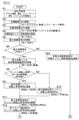
次に、車両コントローラ20で実行される制御処理のフローを説明する。図12A及び図12Bは、車両コントローラ20で実行される処理内容を示すフローチャートである。図12A及び図12Bのフローチャートによる処理は、たとえば10msecの時間間隔で繰り返される。
Next, the flow of the control process executed by the
ステップS1では、目標駆動力演算部201は、アクセルセンサ25からのアクセル開度、車速センサ26からの車速及びS/Mセンサ27からの走行モードの各信号、及びバッテリコントローラ23からのバッテリ入力可能電力を入力し、ステップS2において、図3に示す処理を実行して目標駆動力Fdを求める。 In step S1, the target driving
ステップS3では、目標消費電力演算部202は、図4に示す処理を実行して目標消費電力Pcを演算する。ステップS4では、目標到達エンジン回転速度演算部203は、図5に示す処理を実行して目標到達エンジン回転速度Ntを演算する。ステップS5では、目標消費電力演算部202は、図4に示す処理を実行して電力消費要求を演算する。 In step S3, the target power
ステップS6では、電力消費要求があるか否かを判定し、電力消費要求があると判断した場合はステップS7に進み、電力消費要求がないと判断した場合にはステップS22に進む。ステップS7では、電力消費による要求補填減速度演算部2041は、図7に示す処理を実行して電力消費による要求補填減速度を演算する。ステップS8では、目標エンジン回転速度演算部2042は、ステップS4の演算処理で演算された目標到達エンジン回転速度Ntと、目標到達回転速度の前回値Ncとの差を演算し、差が所定値より大きい場合にはステップS9に進み、差が所定値以下である場合にはステップS10に進む。
In step S6, it is determined whether or not there is a power consumption request, and if it is determined that there is a power consumption request, the process proceeds to step S7, and if it is determined that there is no power consumption request, the process proceeds to step S22. In step S7, the demand compensation /
ステップS9では、目標エンジン回転速度演算部2042は、電力消費による要求補填減速度DRを入力し、図8に示す第1マップを参照して、基本目標エンジン回転上昇率NRBuを演算する。ステップS10では、目標エンジン回転速度演算部2042は、目標到達エンジン回転速度と、実際のエンジン回転速度との差分(Nt-Nc)に基づき、図8に示す第2マップを参照して、伸び感演出用エンジン回転速度上昇率NRGuを演算する。ステップS11では、目標エンジン回転速度演算部2042は、図8に示す処理を実行して、電力消費要求時のエンジン回転上昇率NRDuを演算する。ステップS12では、目標エンジン回転速度演算部2042は、車速を入力し、図8に示す第3マップを参照して、非ドライバ操作時のエンジン回転上昇率NRNuを演算する。ステップS13では、目標エンジン回転速度演算部2042は、図8に示す処理を実行して、目標エンジン回転速度NBuを演算する。
In step S9, the target engine rotation
ステップS14では、目標エンジン回転速度演算部2043は、電力消費要求時のドライバ・アクセル操作判定フラグの状態に基づき、エンジン回転減少時にドライバによるアクセル操作があるか否かを判定する。アクセル操作があると判定する場合には、ステップS15に進み、アクセル操作がないと判定する場合には、ステップS18に進む。 In step S14, the target engine rotation
ステップS15では、目標エンジン回転速度演算部2043は、目標消費電力Pcを入力として、図9に示す第4マップを参照して、基本目標エンジン回転減少率NRBdを演算する。ステップS16では、目標エンジン回転速度演算部2043は、図8に示す第5マップを参照して、アクセル開度変化量に対応するゲインを演算する。 In step S15, the target engine rotation
ステップS17では、目標エンジン回転速度演算部2043は、図9に示す処理を実行して、ドライバ操作判定時の目標エンジン回転減少率を演算する。ステップS18では、目標エンジン回転速度演算部2043は、車速を入力とし、図9に示す第6マップを参照して、非ドライバ操作時の目標エンジン回転減少率を演算する。 In step S17, the target engine rotation
ステップS19では、目標エンジン回転速度演算部2043は、図9に示す処理を実行して、電力消費要求時の目標エンジン回転減少率を演算する。ステップS20では、目標エンジン回転速度演算部2043は、図9に示す処理を実行して、エンジン回転急変抑制用の目標エンジン回転減少率NRkdを演算する。ステップS21では、目標エンジン回転速度演算部2043は、図9に示す処理を実行して、目標エンジン回転速度NBdを演算する。 In step S19, the target engine rotation
ステップS22では、発電機モータ回転速度指令値演算部2044は、図10に示す処理を実行して、最終目標エンジン回転速度Ncを演算する。ステップS23では、目標駆動モータトルク演算部205は、図11に示す処理を実行して、目標駆動モータトルク指令値Tmを演算する。 In step S22, the generator motor rotation speed command
次に、ハイブリッド車両1を代表的なシーンに適用した場合の各パラメータの動向を説明する。図13及び図14は、モータリング制御を実行する場合において、電力消費による要求補填減速度の増加によりエンジン11の回転速度を増加させるときのタイムチャートである。図15~図17は、モータリング制御を実行する場合において、電力消費による要求補填減速度が減少し、かつ、エンジン11を発電機12で駆動させるときのタイムチャートである。 Next, the trend of each parameter when the
図13は、同図(b)のアクセル開度-時間のグラフに示すように、ドライバがハイブリッド車両を運転している状態であって、時間t0~t1の間はアクセルを一定量で踏み込み、時間t1以降、アクセルを離したシーンを示す。 FIG. 13 shows a state in which the driver is driving a hybrid vehicle as shown in the graph of accelerator opening degree-time in FIG. 13B, and the accelerator is depressed by a constant amount during the time t0 to t1. The scene where the accelerator is released after the time t1 is shown.
このドライバのアクセル操作により、同図(а)の車速-時間のグラフに示すように、時間t0~t1の間は定速走行がされ、時刻t1以降車速が徐々に減少する。同図(а)の車速-時間のグラフは、車速が高い場合、車速が低い場合をそれぞれ線の太さを変えて表し、同図(d)~(f)の各グラフにおけるパラメータの変化線の太さは、車速(高・低)にそれぞれ対応するように示したものである。同図(c)の電力-時間のグラフは、図2の目標消費電力演算部202で演算される要求回生電力と、バッテリコントローラ23で演算されるバッテリ入力可能電力と、図2の目標消費電力演算部202で演算される目標消費電力Pcを示す。同図(d)の電力消費による要求補填減速度-時間のグラフは、図6の電力消費による要求補填減速度演算部2041で演算される、電力消費による要求補填減速度DRを示している。同図(e)のエンジン回転速度-時間のグラフは、図2の変化率付与後目標エンジン回転速度演算部204で演算される変化率付与後目標エンジン回転速度(最終目標エンジン回転速度Nc)を示したものである。同図(f)の駆動力-時間のグラフは、電動機13の駆動力である。 By the accelerator operation of this driver, as shown in the graph of vehicle speed-time in the figure (а), constant speed driving is performed during the time t0 to t1, and the vehicle speed gradually decreases after the time t1. The graph of vehicle speed-time in the figure (а) shows the case where the vehicle speed is high and the case where the vehicle speed is low by changing the thickness of the line, and the change line of the parameter in each graph of the figure (d) to (f). The thickness of is shown to correspond to the vehicle speed (high and low), respectively. The power-time graph of FIG. 2C shows the required regenerative power calculated by the target power
同図(c)に示すように、車速が高い場合の要求回生電力は、ドライバ要求駆動力(目標駆動力に相当)が同じ場合、車速が低い場合の要求回生電力よりも高い。目標消費電力は、要求回生電力とバッテリ入力可能電力との差に相当し、バッテリへの入力可能電力が同じ場合、車速が高い場合の目標回生電力は、車速が低い場合の目標回生電力よりも高い。 As shown in FIG. 3C, the required regenerative power when the vehicle speed is high is higher than the required regenerative power when the vehicle speed is low when the driver required driving force (corresponding to the target driving force) is the same. The target power consumption corresponds to the difference between the required regenerative power and the battery inputtable power, and when the inputtable power to the battery is the same, the target regenerated power when the vehicle speed is high is larger than the target regenerated power when the vehicle speed is low. high.
同図(d)に示すように、車速が高い場合の電力消費による要求補填減速度と、車速が低い場合の電力消費による要求補填減速度は同一である。すなわち、車速が異なり、かつ、電力消費による要求補填減速度が同一の場合には、車速が低いほど、目標消費電力Pcが小さくなる。同図(e)に示すように、エンジン回転速度は、時間t1から立ち上がり、初期のエンジン回転速度の変化率は低い車速と高い車速で同一である。車速が低い場合には、エンジン回転速度は時間t2以降、時間t1~t2までの変化率よりも小さい変化率で上昇する。一方、車速が高い場合には、エンジン回転速度は時間t1~t3まで、高い変化率で上昇し、時間t3以降、時間t1~t3までの変化率よりも小さい変化率で上昇する。同図(f)に示すように、回生方向の駆動力は時間t1から増加し始める。回生方向の駆動力は、低い車速と高い車速で同一である。 As shown in FIG. 3D, the required compensation / deceleration due to power consumption when the vehicle speed is high and the required compensation / deceleration due to power consumption when the vehicle speed is low are the same. That is, when the vehicle speeds are different and the required compensation deceleration due to power consumption is the same, the lower the vehicle speed, the smaller the target power consumption Pc. As shown in FIG. 3E, the engine rotation speed rises from time t1, and the rate of change in the initial engine rotation speed is the same between the low vehicle speed and the high vehicle speed. When the vehicle speed is low, the engine rotation speed increases at a rate of change smaller than the rate of change from time t1 to t2 after time t2. On the other hand, when the vehicle speed is high, the engine rotation speed increases at a high rate of change from time t1 to t3, and increases at a rate smaller than the rate of change from time t3 to time t1 to t3. As shown in the figure (f), the driving force in the regenerative direction starts to increase from time t1. The driving force in the regenerative direction is the same for low vehicle speed and high vehicle speed.
図13に示すように、電力消費による要求補填減速度が車速によらず同じ場合には、制動力が小さいことの違和感無く、車速が低いほど、エンジン回転速度が小さくなり、静粛性を高めることができる。 As shown in FIG. 13, when the required compensating deceleration due to power consumption is the same regardless of the vehicle speed, there is no sense of discomfort that the braking force is small, and the lower the vehicle speed, the smaller the engine rotation speed and the quieterness. Can be done.
また、エンジン回転速度が立ち上がる立ち上がり期間(時間t1~t2又は時間t1~t3に相当)は、エンジン回転速度の変化率が高いため、ドライバからの回生による減速要求に対して、ドライバに対して過渡的な減速感を与えることができる。また、立ち上がり期間を経過した後のエンジン回転速度は、立ち上がり期間の変化率よりも低い変化率で推移する。これにより、継続した減速感をドライバに与えることができる。 Further, since the rate of change of the engine rotation speed is high during the rising period (corresponding to the time t1 to t2 or the time t1 to t3) at which the engine rotation speed rises, it is transient to the driver in response to the deceleration request due to regeneration from the driver. Can give a feeling of deceleration. Further, the engine speed after the rise period has elapsed changes at a rate of change lower than the rate of change during the start-up period. This makes it possible to give the driver a continuous feeling of deceleration.
図14は、同図(b)のアクセル開度-時間のグラフに示すように、ドライバがハイブリッド車両を運転している状態であって、時間t0~t1の間はアクセルを一定量で踏み込み、時間t1以降、アクセルを離したシーンを示す。 FIG. 14 shows a state in which the driver is driving a hybrid vehicle as shown in the graph of accelerator opening degree-time in FIG. 14B, and the accelerator is depressed by a constant amount during the time t0 to t1. The scene where the accelerator is released after the time t1 is shown.
このドライバのアクセル操作により、同図(а)の車速-時間のグラフに示すように、時間t0~t1の間は定速走行がされ、時刻t1以降車速が徐々に減少する。同図(а)の車速-時間のグラフは、車速が高い場合、車速が低い場合をそれぞれ線の太さを変えて表し、同図(d)~(f)の各グラフにおけるパラメータの変化線の太さは、車速(高・低)にそれぞれ対応するように示したものである。同図(а)~(f)のグラフで示されるパラメータは、図13の(а)~(f)のグラフで示されるパラメータと同じである。 By the accelerator operation of this driver, as shown in the graph of vehicle speed-time in the figure (а), constant speed driving is performed during the time t0 to t1, and the vehicle speed gradually decreases after the time t1. The graph of vehicle speed-time in the figure (а) shows the case where the vehicle speed is high and the case where the vehicle speed is low by changing the thickness of the line, and the change line of the parameter in each graph of the figure (d) to (f). The thickness of is shown to correspond to the vehicle speed (high and low), respectively. The parameters shown in the graphs (а) to (f) of the same figure are the same as the parameters shown in the graphs (а) to (f) of FIG.
同図(c)に示すように、車速が高い場合と低い場合とで要求回生電力と同一であり、目標消費電力も同一である。同図(d)に示すように、車速が高い場合の電力消費による要求補填減速度は、車速が低い場合の電力消費による要求補填減速度よりも低い。 As shown in FIG. 3C, the required regenerative power is the same when the vehicle speed is high and when the vehicle speed is low, and the target power consumption is also the same. As shown in FIG. 3D, the required compensating deceleration due to power consumption when the vehicle speed is high is lower than the required compensating deceleration due to power consumption when the vehicle speed is low.
同図(e)に示すように、車速が高い場合と低い場合とで目標到達エンジン回転速度は、同一である。エンジン回転速度は、時間t1から立ち上がる。車速が低い場合のエンジン回転速度は、時間t2以降、時間t1~t2までの変化率よりも小さい変化率で上昇する。一方、車速が高い場合には、エンジン回転速度は時間t1~t3まで、高い変化率で上昇し、時間t3以降、時間t1~t3までの変化率よりも小さい変化率で上昇する。同図(f)に示すように、回生方向の駆動力は、時間t1から減少を開始する。車速が低い場合と車速が高い場合とを比較すると、車速が低い方が、回生方向の駆動力が大きい。すなわち、車速が異なり、要求回生電力が同じ場合には、車速が低いほど、駆動力は大きくなる。 As shown in FIG. 3E, the target reaching engine speed is the same when the vehicle speed is high and when the vehicle speed is low. The engine speed starts from time t1. When the vehicle speed is low, the engine rotation speed increases at a rate of change smaller than the rate of change from time t1 to t2 after time t2. On the other hand, when the vehicle speed is high, the engine rotation speed increases at a high rate of change from time t1 to t3, and increases at a rate smaller than the rate of change from time t3 to time t1 to t3. As shown in FIG. 3 (f), the driving force in the regenerative direction starts to decrease from time t1. Comparing the case where the vehicle speed is low and the case where the vehicle speed is high, the lower the vehicle speed, the larger the driving force in the regenerative direction. That is, when the vehicle speed is different and the required regenerative power is the same, the lower the vehicle speed, the larger the driving force.
図15は、同図(b)のアクセル開度-時間のグラフに示すように、ドライバがハイブリッド車両を運転している状態であって、時間t0~t1の間はアクセルを一定量で踏み込み、時間t1以降、アクセルを離したシーンを示す。 FIG. 15 shows a state in which the driver is driving a hybrid vehicle as shown in the graph of accelerator opening degree-time in FIG. 15B, and the accelerator is depressed by a constant amount during the time t0 to t1. The scene where the accelerator is released after the time t1 is shown.
同図(а)のSOC-時間のグラフは、SOCが高い場合、SOCが低い場合をそれぞれ線の太さを変えて表し、同図(а)、(c)~(e)のの各グラフにおけるパラメータの変化線の太さは、SOC(大・小)にそれぞれ対応するように示したものである。同図(c)~(f)のグラフで示されるパラメータは、図13の(c)~(f)のグラフで示されるパラメータと同じである。 The SOC-time graph in the figure (а) shows the case where the SOC is high and the case where the SOC is low by changing the line thickness, and each graph in the figure (а), (c) to (e). The thickness of the change line of the parameter in is shown so as to correspond to SOC (large and small) respectively. The parameters shown in the graphs (c) to (f) of FIG. 13 are the same as the parameters shown in the graphs (c) to (f) of FIG.
同図(c)に示すように、SOCが大きい場合のバッテリ入力可能電力は、SOCが小さい場合のバッテリ入力可能電力より低くなり、SOCが大きい場合の目標消費電力は、SOCが小さい場合の目標消費電力より多くなる。同図(d)に示すように、SOCが大きい場合には、バッテリ14へ充電できる電力が小さいため、エンジン11の駆動による消費電力が大きくなるため、電力消費による要求補填減速度が大きくなる。すなわち、SOCが大きい場合の電力消費による要求補填減速度は、SOCが小さい場合の電力消費による要求補填減速度より大きくなる。 As shown in FIG. 3C, the battery input power when the SOC is large is lower than the battery input power when the SOC is small, and the target power consumption when the SOC is large is the target when the SOC is small. It consumes more power. As shown in FIG. 3D, when the SOC is large, the power that can be charged to the
同図(e)に示すように、エンジン回転速度は、時間t1から立ち上がり、大きな変化率で上昇し、時間t2以降、小さな変化率で上昇する。時間t1~t2の間で、SOCが大きいほど、エンジン回転速度の変化率は大きくなる。 As shown in FIG. 3E, the engine rotation speed rises from time t1 and rises at a large rate of change, and after time t2, rises at a small rate of change. During the time t1 to t2, the larger the SOC, the larger the rate of change in the engine rotation speed.
また、エンジン回転速度の立ち上がり時点から、エンジン回転速度が目標到達エンジン回転速度に到達するまでの期間において、時間t1~t2の間のエンジン回転速度の変化率(基本目標エンジン回転上昇率に相当)は、時間t2~t3の間のエンジン回転速度の変化率(伸び感演出用エンジン回転上昇率に相当)より大きい。 Further, the rate of change in the engine speed between the time t1 and t2 (corresponding to the basic target engine speed increase rate) in the period from the start of the engine speed to the time when the engine speed reaches the target engine speed. Is larger than the rate of change in the engine rotation speed between the times t2 and t3 (corresponding to the rate of increase in the engine rotation for producing a feeling of elongation).
図16は、同図(а)のアクセル開度-時間のグラフに示すように、ドライバがハイブリッド車両を運転している状態であって、時間t0~t1の間はアクセルを踏み込んでおらず、時間t1以降、アクセルを徐々に踏み込み、時間t5以降、アクセルをさらに踏み込んだシーンを示す。 FIG. 16 shows a state in which the driver is driving a hybrid vehicle, and the accelerator is not depressed during the time t0 to t1, as shown in the graph of accelerator opening degree-time in the figure (а). A scene in which the accelerator is gradually depressed after the time t1 and the accelerator is further depressed after the time t5 is shown.
このドライバのアクセル操作により、同図(а)のアクセル開度-時間のグラフ及び同図(c)のアクセル開度変化量-時間に示すように、時間t0~t1の間はアクセル開度がゼロとなり、時間t1~t5の間は、アクセル開度の変化量が大きくなり、アクセル開度は所定の傾きで上昇し、時間t5以降は、アクセル開度の変化量がさらに大きくなり、アクセル開度は、さらに大きい傾きで上昇する。 By the accelerator operation of this driver, as shown in the graph of accelerator opening-time in the figure (а) and the amount of change in accelerator opening-time in the figure (c), the accelerator opening is changed during the time t0 to t1. It becomes zero, the amount of change in the accelerator opening becomes large during the time t1 to t5, the accelerator opening increases with a predetermined inclination, and after the time t5, the amount of change in the accelerator opening becomes even larger and the accelerator is opened. The degree rises with an even larger slope.
同図(b)の目標消費電力-時間のグラフは、図2の目標消費電力演算部202で演算される目標消費電力Pcを示したものである。同図(f)のエンジン回転速度-時間のグラフは、図2の変化率付与後目標エンジン回転速度演算部204で演算される変化率付与後目標エンジン回転速度(最終目標エンジン回転速度Nc)を示したものである。 The graph of target power consumption-time in FIG. 2B shows the target power consumption Pc calculated by the target power
同図(c)に示すように、時間t1でアクセル開度の変化量がドライバ・アクセル操作判定閾値より大きくなると、図9に示す処理において、ドライバによるアクセル操作の判定結果を示すフラグがセット状態となる。時間t1で、車速が高い場合の目標消費電力は、目標消費電力閾値Pthよりも高い。目標消費電力閾値Pthは、図9の制御ブロックの第4マップにおいて、グラフの屈曲点の目標消費電力に相当する。目標消費電力が目標消費電力閾値Pthより高い場合には、図9に示す処理において、エンジン回転減少率は一定値(ゼロ)になる。そのため、同図(e)に示すように、車速が低い場合には、時間t1~t2の間で、エンジン回転減少率はゼロになる。また、車速が高い場合には、時間t1~t3の間で、エンジン回転減少率はゼロになる。 As shown in FIG. 9C, when the amount of change in the accelerator opening becomes larger than the driver / accelerator operation determination threshold value at time t1, a flag indicating the determination result of the accelerator operation by the driver is set in the process shown in FIG. Will be. The target power consumption when the vehicle speed is high at the time t1 is higher than the target power consumption threshold Pth. The target power consumption threshold Pth corresponds to the target power consumption at the inflection point of the graph in the fourth map of the control block of FIG. When the target power consumption is higher than the target power consumption threshold value Pth, the engine rotation reduction rate becomes a constant value (zero) in the process shown in FIG. Therefore, as shown in FIG. 3E, when the vehicle speed is low, the engine rotation reduction rate becomes zero during the time t1 to t2. Further, when the vehicle speed is high, the engine rotation reduction rate becomes zero during the time t1 to t3.
時間t2で、車速が低い場合の目標消費電力が目標消費電力閾値Pthより低くなるため、図9に示す処理において、エンジン回転減少率は一定値(ゼロ)よりも大きくなる。同図(e)に示すように、エンジン回転減少率は上昇し始める。車速が高い場合には、車速が低い場合と比較して目標消費電力Pcが大きいため、目標消費電力が目標消費電力閾値Pthより低くなるタイミングは、車速が低い場合のタイミングよりも遅くなる。時間t3で、目標消費電力が目標消費電力閾値Pthより低くなり、エンジン回転減少率は上昇し始める。時間t2~t4の間で、車速が高い方と車速が低い方を比べた場合に、エンジン回転減少率の最大値(到達減少率)は、車速が高い方が大きい。 At time t2, the target power consumption when the vehicle speed is low becomes lower than the target power consumption threshold value Pth, so that the engine rotation reduction rate becomes larger than a constant value (zero) in the process shown in FIG. As shown in the figure (e), the engine rotation reduction rate begins to increase. When the vehicle speed is high, the target power consumption Pc is larger than when the vehicle speed is low, so that the timing when the target power consumption becomes lower than the target power consumption threshold Pth is later than the timing when the vehicle speed is low. At time t3, the target power consumption becomes lower than the target power consumption threshold Pth, and the engine rotation reduction rate begins to increase. When comparing the one with a high vehicle speed and the one with a low vehicle speed between the times t2 and t4, the maximum value (reaching reduction rate) of the engine rotation reduction rate is larger when the vehicle speed is high.
同図(b)に示すように、時間t4で目標消費電力はゼロになる。同図(e)に示すように、エンジン回転速度も時間t4でゼロになる。車速が高い場合には、時間t3~t4の間でエンジン回転速度を高い状態からゼロに減少させている。車速が低い場合には、時間t2~t4の間でエンジン回転速度を高い状態からゼロに減少させている。すなわち、車速が低い方が、エンジン回転数が高い状態から低い状態になるまでの時間が長くなっている。 As shown in FIG. 6B, the target power consumption becomes zero at time t4. As shown in the figure (e), the engine rotation speed also becomes zero at time t4. When the vehicle speed is high, the engine speed is reduced from the high state to zero during the time t3 to t4. When the vehicle speed is low, the engine speed is reduced from high to zero during the time t2 to t4. That is, the lower the vehicle speed, the longer the time from the high engine speed to the low engine speed.
なお、本実施形態では、エンジン回転速度の変化を解除するタイミングを目標消費電力で設定したが、目標消費電力の代わりにアクセル開度でもよい。図4に示す処理において、目標消費電力Pcは車速で決まり、バッテリ入力可能電力を一定にした場合には、車速が高いほど、目標消費電力Pcは大きくなる。そのため、同図(а)に示すように、目標消費電力閾値Pthは、車速に応じたアクセル開度に置き換えることができる。車速が高い場合には、目標消費電力閾値Pthはアクセル開度閾値AthHに置き換えられ、車速が低い場合には、目標消費電力閾値Pthはアクセル開度閾値AthLに置き換えられる。In the present embodiment, the timing for canceling the change in the engine rotation speed is set by the target power consumption, but the accelerator opening may be used instead of the target power consumption. In the process shown in FIG. 4, the target power consumption Pc is determined by the vehicle speed, and when the battery inputtable power is constant, the higher the vehicle speed, the larger the target power consumption Pc. Therefore, as shown in the figure (а), the target power consumption threshold value Pth can be replaced with the accelerator opening degree according to the vehicle speed. When the vehicle speed is high, the target power consumption threshold Pth is replaced with the accelerator opening threshold AthH , and when the vehicle speed is low, the target power consumption threshold Pth is replaced with the accelerator opening threshold AthL .
そして、図16に示す走行シーンにおいて、車速が低い場合には、アクセル開度が閾値AthL以上になった場合に、エンジン回転速度の変化の制限が解除されて、エンジン回転速度の減少率が上昇する。また、車速が高い場合には、アクセル開度が閾値AthH以上になった場合に、エンジン回転速度の変化の制限が解除されて、エンジン回転速度の減少率が上昇する。また、エンジン回転速度の変化の制限を解除するための、アクセル開度の閾値(AthL、AthH)は、エンジン回転速度の減少率が大きいほど、高い値になり、または、車両の車速が高いほど、高い値になる。これにより、エンジン回転速度が低い場合には、エンジン音が小さいため、静寂性を保ちつつ、エンジン回転速度の変化の制限を解除できる。Then, in the traveling scene shown in FIG. 16, when the vehicle speed is low, the restriction on the change in the engine rotation speed is released when the accelerator opening degree becomes the threshold value AthL or more, and the reduction rate of the engine rotation speed is reduced. Rise. Further, when the vehicle speed is high, when the accelerator opening degree becomes equal to or higher than the threshold value AthH , the restriction on the change in the engine rotation speed is lifted, and the reduction rate of the engine rotation speed increases. Further, the threshold value of the accelerator opening ( AthL , AthH ) for releasing the restriction of the change of the engine rotation speed becomes higher as the reduction rate of the engine rotation speed is larger, or the vehicle speed of the vehicle becomes higher. The higher the value, the higher the value. As a result, when the engine rotation speed is low, the engine noise is small, so that the restriction on the change in the engine rotation speed can be lifted while maintaining quietness.
図17は、同図(а)のアクセル開度-時間のグラフに示すように、ドライバがハイブリッド車両を運転している状態であって、時間t0~t1の間はアクセルを踏み込んでおらず、時間t1以降、アクセルを徐々に踏み込み、時間t3以降、アクセル開度が一定になるようにアクセルを操作した時のシーンを示す。同図(а)~(f)のグラフで示されるパラメータは、図16の(а)~(f)のグラフで示されるパラメータと同じである。 FIG. 17 shows a state in which the driver is driving a hybrid vehicle, and the accelerator is not depressed during the time t0 to t1, as shown in the graph of accelerator opening degree-time in the figure (а). The scene when the accelerator is gradually depressed after the time t1 and the accelerator is operated so that the accelerator opening becomes constant after the time t3 is shown. The parameters shown in the graphs (а) to (f) of the same figure are the same as the parameters shown in the graphs (а) to (f) of FIG.
このアクセル操作により、同図(а)のアクセル開度-時間のグラフ及び同図(c)のアクセル開度変化量-時間に示すように、時間t0~t1の間はアクセル開度がゼロとなり、時間t1~t3の間は、アクセル開度の変化量が大きくなり、アクセル開度は所定の傾きで上昇し、時間t3以降は、アクセル開度は一定になる。 By this accelerator operation, as shown in the graph of accelerator opening-time in the figure (а) and the amount of change in accelerator opening-time in the figure (c), the accelerator opening becomes zero during the time t0 to t1. During the time t1 to t3, the amount of change in the accelerator opening becomes large, the accelerator opening increases with a predetermined inclination, and after the time t3, the accelerator opening becomes constant.
同図(b)に示すように、時間t2で、目標消費電力が目標消費電力閾値Pthより低くなるため、エンジン回転速度の変化の制限が解除され、同図(f)に示すように、エンジン回転速度の減少が開始する。時間t2~t3の間では、アクセル開度の上昇に伴い、車両に対する要求減速度が減少する。そして、時間t2~t3の間では、要求減速度が小さいほど、エンジン回転速度の減少率が大きくなっている。また、時間t2~t3の間では、モータリング制御による消費電力(目標消費電力Pcに相当)が小さいほど、エンジン回転速度の減少率が大きくなっている。 As shown in FIG. 2B, since the target power consumption becomes lower than the target power consumption threshold Pth at time t2, the restriction on the change in the engine rotation speed is lifted, and as shown in FIG. The rotation speed starts to decrease. During the time t2 to t3, the required deceleration for the vehicle decreases as the accelerator opening degree increases. Then, during the time t2 to t3, the smaller the required deceleration, the larger the decrease rate of the engine rotation speed. Further, during the time t2 to t3, the smaller the power consumption by the motoring control (corresponding to the target power consumption Pc), the larger the reduction rate of the engine rotation speed.
同図(c)に示すように、アクセル開度の変化量がドライバ・アクセル操作判定閾値より低くなるため、ドライバによるアクセル操作の判定結果を示すフラグがクリア状態となる。同図(b)に示すように、目標消費電力が時間t3以降一定になる。同図(e)に示すように、エンジン回転減少率は、時間t3で減少を開始し、時間t3~t4の間で滑らかに減少し、時間t4~時間t5の間、一定値で推移する。 As shown in FIG. 3C, since the amount of change in the accelerator opening is lower than the driver / accelerator operation determination threshold value, the flag indicating the determination result of the accelerator operation by the driver is cleared. As shown in FIG. 3B, the target power consumption becomes constant after the time t3. As shown in FIG. 3E, the engine rotation reduction rate starts to decrease at time t3, decreases smoothly between time t3 and t4, and changes at a constant value between time t4 and time t5.
同図(e)に示すように、エンジン回転減少率は、時間t3で減少を開始し、時間t3~t4の間で滑らかに減少する。エンジン回転減少率は、時間t4で一定の非ドライバ操作時目標エンジン回転減少率となり、時間t4~時間t5の間、一定の非ドライバ操作時目標エンジン回転減少率で推移する。同図(f)に示すように、時間t5でエンジン回転速度は目標到達エンジン回転速度に一致する。 As shown in FIG. 3E, the engine rotation reduction rate starts decreasing at time t3 and decreases smoothly between hours t3 and t4. The engine rotation reduction rate becomes a constant non-driver operation target engine rotation reduction rate at time t4, and changes at a constant non-driver operation target engine rotation reduction rate from time t4 to time t5. As shown in the figure (f), the engine rotation speed coincides with the target reaching engine rotation speed at time t5.
上記のように本実施形態では、モータリング制御を実行する場合において、要求減速度の増加によりエンジン回転速度を増加させるときには、モータリング制御による消費電力が大きいほどエンジン回転速度の変化率が大きくなるように、エンジン回転速度を設定する。これにより、電力を十分に消費でき、ドライバの減速意図に対して十分な減速感を得ることができる。その結果として、ドライバに与える違和感を緩和できる。 As described above, in the present embodiment, when the engine rotation speed is increased by increasing the required deceleration in the case of executing the motoring control, the larger the power consumption by the motoring control, the larger the rate of change of the engine rotation speed. So, set the engine speed. As a result, sufficient power can be consumed, and a sufficient deceleration feeling can be obtained with respect to the deceleration intention of the driver. As a result, the discomfort given to the driver can be alleviated.
また本実施形態では、モータリング制御を実行する場合において、要求減速度の増加によりエンジン回転速度を増加させるときには、要求減速度が大きいほどエンジン回転速度の変化率が大きくなるように、エンジン回転速度を設定する。これにより、電力を十分に消費でき、ドライバの減速意図に対して十分な減速感を得ることができる。その結果として、ドライバに与える違和感を緩和できる。 Further, in the present embodiment, when the engine rotation speed is increased by increasing the required deceleration in the case of executing the motoring control, the engine rotation speed is increased so that the larger the required deceleration is, the larger the rate of change of the engine rotation speed is. To set. As a result, sufficient power can be consumed, and a sufficient deceleration feeling can be obtained with respect to the deceleration intention of the driver. As a result, the discomfort given to the driver can be alleviated.
また本実施形態では、要求減速度の増加によりエンジン回転速度を増加させるときには、要求減速度の内、モータリング制御による要求減速度が大きいほど、エンジン回転速度の変化率を大きくなるように、エンジン回転速度を設定する。これにより電力を十分に消費でき、ドライバの減速意図に対して十分な減速感を得ることができる。その結果として、ドライバに与える違和感を緩和できる。 Further, in the present embodiment, when the engine rotation speed is increased by increasing the required deceleration, the larger the required deceleration by the motoring control among the required decelerations, the larger the rate of change of the engine rotation speed is. Set the rotation speed. As a result, sufficient power can be consumed, and a sufficient deceleration feeling can be obtained with respect to the driver's deceleration intention. As a result, the discomfort given to the driver can be alleviated.
また本実施形態では、モータリング制御を実行する場合において、要求減速度の増加によりエンジン回転速度を増加させるときには、回転速度の増加が開始する時点からの経過時間に応じて、エンジン回転速度の上昇率を制御する。これにより、ドライバの減速意図に対して十分な減速感を得ることができ、また回転速度の増加が開始する時点からの経過時間が大きくなるほど、言い換えるとエンジン回転速度が目標到達回転速度に近づくほどエンジン回転速度の変化を小さくすることができ、エンジン回転速度の変化に伴うエンジン音の変化を緩和することで静寂性を高めることができる。 Further, in the present embodiment, when the engine rotation speed is increased by increasing the required deceleration in the case of executing the motoring control, the engine rotation speed increases according to the elapsed time from the time when the increase of the rotation speed starts. Control the rate. As a result, a sufficient deceleration feeling can be obtained for the driver's deceleration intention, and the longer the elapsed time from the time when the rotation speed starts to increase, in other words, the closer the engine rotation speed approaches the target reaching rotation speed. The change in the engine rotation speed can be reduced, and the quietness can be enhanced by alleviating the change in the engine sound due to the change in the engine rotation speed.
また本実施形態では、要求減速度に基づき、エンジン11の目標回転速度を演算し、モータリング制御を実行する場合において、要求減速度の増加によりエンジン回転速度を増加させるときには、目標回転速度と上昇率に基づく回転速度との差分が小さいほどエンジン回転速度の上昇率が小さくなるように、エンジン回転速度を設定する。これにより、エンジンブレーキによる減速感の伸びを実現できる。またエンジン回転速度が目標到達回転速度に近づくほどエンジン回転速度の変化を小さくすることができ、エンジン回転速度の変化に伴うエンジン音の変化を緩和することで静寂性を高めることができる。 Further, in the present embodiment, when the target rotation speed of the
また本実施形態では、要求減速度に基づき、エンジン11の目標回転速度を演算し、モータリング制御を実行する場合において、要求減速度の増加によりエンジン回転速度を増加させるときには、目標回転速度が大きいほど回転速度の増加が開始する時点から所定期間までのエンジン回転速度の変化率が大きくなるように、エンジン回転速度を設定する。これにより、ドライバの減速意図に対して十分な減速感を得ることができる。 Further, in the present embodiment, when the target rotation speed of the
また本実施形態において、ハイブリッド車両1は、走行速度に対して設定される目標駆動力のプロファイルが異なる複数の走行モードの設定が可能とされている。そして、複数の走行モードは、アクセルの所定操作量に対して、回生方向の第1駆動力を発生する第1モードと、アクセルの所定操作量に対して、回生方向の第2駆動力を発生する第2モードとを含んでいる。第1駆動力は第2駆動力より大きくなるように設定されている。例えば、ユーザが、走行モードを切り替えるスイッチを操作して、第1モードと第2モードを切り替える。車両の走行中に、ドライバがアクセルを緩めて、いわゆる回生モードになった場合に、第1モードを選択したときの減速度は、第2モードを選択したときの減速度よりも大きくなる。本実施形態では、モータリング制御を実行している状態で加速要求がある場合にまたは要求減速度が小さくなる場合に、エンジン回転速度が高いときには、次の加速に備えてエンジン回転速度を高い減少率で減少させている。そして、第1走行モードを選択した場合には、エンジン回転速度の減少率がより高くなるため、次の加速の時には、加速と同時にエンジン回転速度をより増加させることができ、その際のエンジン音の変化によってドライバに対して加速感を与えることができる。 Further, in the present embodiment, the
また本実施形態では、第1モードが設定され、かつ、モータリング制御が実行される場合において、要求減速度が減少し、発電機12によるエンジン11の駆動が要求され、かつ、エンジン11の回転による消費電力が所定値未満であるときには、エンジンの回転速度を低下するように、エンジンの回転速度を設定する。これにより、次の加速の時には、ドライバに対して加速感を与えることができる。なお、第1モードと第2モードの選択は、シフトポジションの切り換えで行ってもよい。例えば、ノーマル走行モードが設定されている状態で、シフトポジションがブレーキポジションに設定されている場合には、第1モードが選択され、ノーマル走行モードが設定されている状態で、シフトポジションがドライブポジションに設定されている場合には、第2モードが選択される。 Further, in the present embodiment, when the first mode is set and the motoring control is executed, the required deceleration is reduced, the
1…ハイブリッド車両
11…エンジン
111…出力軸
112…増速機
12…発電機
121…回転軸
13…電動機
131…回転軸
132…減速機
14…バッテリ
141…第1インバータ
142…第2インバータ
15…駆動輪
16…駆動車軸
17…ディファレンシャルギヤ
171…ギヤ入力軸
20…車両コントローラ
21…エンジンコントローラ
22…発電機コントローラ
23…バッテリコントローラ
24…電動機コントローラ
25…アクセルセンサ
26…車速センサ
27…シフトレバースイッチセンサ/走行モードスイッチセンサ1 ...
Claims (3)
前記電動機を回生状態にする場合に、前記エンジンへの燃料供給をカットした状態で、前記発電機により前記エンジンを強制的に回転させることで、前記電動機の出力電力を消費するモータリング制御を、前記車両の要求減速度に応じて実行し、
前記モータリング制御を実行する場合において、前記要求減速度の増加により前記エンジンの回転速度を増加させるときには、前記要求減速度が大きいほど前記エンジンの回転速度の変化率が大きくなるように、前記エンジンの回転速度を設定し、
前記モータリング制御による消費電力が同一であり、前記要求減速度が高い時と低い時とを比較した場合、アクセルを離した後の前記エンジンの回転速度の変化率を、前記要求減速度が低い時より、前記要求減速度が高い時のほうを大きく設定するハイブリッド車両の制御方法。 In a method for controlling a hybrid vehicle including an electric motor for driving a vehicle, a generator for supplying electric power to the electric motor, and an engine for driving the generator.
When the motor is regenerated, the motoring control that consumes the output power of the motor is performed by forcibly rotating the engine with the generator while the fuel supply to the engine is cut. Execute according to the required deceleration of the vehicle ,
In the case of executing the motoring control, when the rotation speed of the engine is increased by increasing the required deceleration, the engine has a larger rate of change in the rotation speed of the engine as the required deceleration increases. Set the rotation speed of
When the power consumption by the motoring control is the same and the required deceleration is high and low, the rate of change in the rotational speed of the engine after the accelerator is released is the rate at which the required deceleration is low. A control method for a hybrid vehicle in which the required deceleration is set to be larger than the time when the required deceleration is high.
前記電動機を回生状態にする場合に、前記エンジンへの燃料供給をカットした状態で、前記発電機により前記エンジンを強制的に回転させることで、前記電動機の出力電力を消費するモータリング制御を、前記車両の要求減速度に応じて実行する制御器を備え、
前記制御器は、前記モータリング制御を実行する場合において、前記要求減速度の増加により前記エンジンの回転速度を増加させるときには、前記要求減速度が大きいほど前記エンジンの回転速度の変化率が大きくなるように、前記エンジンの回転速度を設定し、
前記モータリング制御による消費電力が同一であり、前記要求減速度が高い時と低い時とを比較した場合、アクセルを離した後の前記エンジンの回転速度の変化率を、前記要求減速度が低い時より、前記要求減速度が高い時のほうを大きく設定するハイブリッド車両の制御装置。
A control device used for a hybrid vehicle including an electric motor for driving a vehicle, a generator for supplying electric power to the electric motor, and an engine for driving the generator.
When the motor is regenerated, the motoring control that consumes the output power of the motor is performed by forcibly rotating the engine with the generator while the fuel supply to the engine is cut. It is equipped with a controller that executes according to the required deceleration of the vehicle .
When the controller increases the rotational speed of the engine by increasing the required deceleration in the case of executing the motoring control, the larger the required deceleration, the greater the rate of change in the rotational speed of the engine. So, set the rotation speed of the engine,
When the power consumption by the motoring control is the same and the required deceleration is high and low, the rate of change in the rotational speed of the engine after the accelerator is released is the same as the required deceleration is low. A control device for a hybrid vehicle that sets the required deceleration higher than the time.
Applications Claiming Priority (1)
| Application Number | Priority Date | Filing Date | Title |
|---|---|---|---|
| PCT/JP2017/045216 WO2019116582A1 (en) | 2017-12-15 | 2017-12-15 | Control method for hybrid vehicle and control apparatus for hybrid vehicle |
Publications (2)
| Publication Number | Publication Date |
|---|---|
| JPWO2019116582A1 JPWO2019116582A1 (en) | 2021-02-12 |
| JP7004006B2 true JP7004006B2 (en) | 2022-01-21 |
Family
ID=66820108
Family Applications (1)
| Application Number | Title | Priority Date | Filing Date |
|---|---|---|---|
| JP2019558871A Active JP7004006B2 (en) | 2017-12-15 | 2017-12-15 | Hybrid vehicle control method and control device |
Country Status (8)
| Country | Link |
|---|---|
| US (1) | US11731607B2 (en) |
| EP (1) | EP3725621B1 (en) |
| JP (1) | JP7004006B2 (en) |
| KR (1) | KR102352469B1 (en) |
| CN (1) | CN111479736B (en) |
| MX (1) | MX2020006133A (en) |
| RU (1) | RU2750759C1 (en) |
| WO (1) | WO2019116582A1 (en) |
Families Citing this family (6)
| Publication number | Priority date | Publication date | Assignee | Title |
|---|---|---|---|---|
| RU2749232C1 (en) * | 2017-12-15 | 2021-06-07 | Ниссан Мотор Ко., Лтд. | Method for operation and apparatus for operation of engine of hybrid vehicle |
| US11377086B2 (en) * | 2017-12-15 | 2022-07-05 | Nissan Motor Co., Ltd. | Control method for hybrid vehicle and control apparatus for hybrid vehicle |
| EP3725617B1 (en) * | 2017-12-15 | 2022-01-05 | Nissan Motor Co., Ltd. | Method and device for controlling hybrid vehicle |
| JP7316206B2 (en) * | 2019-12-24 | 2023-07-27 | 株式会社Subaru | vehicle controller |
| US11230288B1 (en) * | 2020-09-28 | 2022-01-25 | GM Global Technology Operations LLC | Optimized regenerative braking for hybrid electric vehicle (HEV) powertrain configurations |
| FR3136725A1 (en) * | 2022-06-17 | 2023-12-22 | Renault S.A.S | Method and system for controlling a hybrid motor vehicle during deceleration |
Citations (5)
| Publication number | Priority date | Publication date | Assignee | Title |
|---|---|---|---|---|
| JP2008049868A (en) | 2006-08-25 | 2008-03-06 | Mazda Motor Corp | Regenerative braking control apparatus of hybrid vehicle |
| JP2010023731A (en) | 2008-07-22 | 2010-02-04 | Toyota Motor Corp | Regenerative controller of hybrid vehicle |
| JP2016049838A (en) | 2014-08-29 | 2016-04-11 | 三菱自動車工業株式会社 | Regeneration control unit |
| JP2016049837A (en) | 2014-08-29 | 2016-04-11 | 三菱自動車工業株式会社 | Regeneration control unit |
| JP2017047821A (en) | 2015-09-03 | 2017-03-09 | トヨタ自動車株式会社 | Hybrid automobile |
Family Cites Families (21)
| Publication number | Priority date | Publication date | Assignee | Title |
|---|---|---|---|---|
| US20020179348A1 (en) * | 2001-05-30 | 2002-12-05 | Goro Tamai | Apparatus and method for controlling a hybrid vehicle |
| US7028793B2 (en) * | 2002-02-08 | 2006-04-18 | Green Vision Technology, Llc | Internal combustion engines for hybrid powertrain |
| JP3894187B2 (en) * | 2003-10-21 | 2007-03-14 | トヨタ自動車株式会社 | POWER OUTPUT DEVICE, ITS CONTROL METHOD, AND AUTOMOBILE MOUNTING THE SAME |
| JP2005253126A (en) * | 2004-03-01 | 2005-09-15 | Nissan Motor Co Ltd | Brake controller of hybrid vehicle and vehicle mounting that controller |
| JP4023625B2 (en) | 2005-10-28 | 2007-12-19 | 本田技研工業株式会社 | Control device for hybrid vehicle |
| JP4271682B2 (en) * | 2005-11-24 | 2009-06-03 | 本田技研工業株式会社 | Control device for motor-driven vehicle |
| JP4743218B2 (en) * | 2008-03-03 | 2011-08-10 | 日産自動車株式会社 | Clutch control device for hybrid vehicle |
| JP5110155B2 (en) * | 2010-11-24 | 2012-12-26 | トヨタ自動車株式会社 | VEHICLE CONTROL DEVICE AND VEHICLE CONTROL METHOD |
| JP5079864B2 (en) * | 2010-12-06 | 2012-11-21 | 日野自動車株式会社 | Regenerative control device, hybrid vehicle, regenerative control method, and program |
| JP5821285B2 (en) * | 2011-05-30 | 2015-11-24 | 日産自動車株式会社 | Engine stop control device for hybrid vehicle |
| DE112011105443T5 (en) * | 2011-07-11 | 2014-03-27 | Toyota Jidosha Kabushiki Kaisha | Vehicle drive control device |
| KR101622525B1 (en) * | 2012-09-11 | 2016-05-18 | 혼다 기켄 고교 가부시키가이샤 | Hybrid vehicle |
| CN105102285B (en) * | 2013-04-04 | 2017-10-24 | 日产自动车株式会社 | The control device of motor vehicle driven by mixed power |
| KR101588790B1 (en) * | 2014-07-29 | 2016-01-26 | 현대자동차 주식회사 | Vehicle control system having motor |
| JP6252519B2 (en) * | 2015-03-06 | 2017-12-27 | トヨタ自動車株式会社 | Control device for hybrid vehicle |
| JP6335852B2 (en) * | 2015-08-05 | 2018-05-30 | 本田技研工業株式会社 | Control device for hybrid vehicle |
| JP6326403B2 (en) * | 2015-12-25 | 2018-05-16 | 本田技研工業株式会社 | Hybrid vehicle |
| JP6315622B2 (en) * | 2016-03-04 | 2018-04-25 | 本田技研工業株式会社 | vehicle |
| JP6680049B2 (en) * | 2016-04-04 | 2020-04-15 | トヨタ自動車株式会社 | Vehicle driving control method |
| JP6620126B2 (en) * | 2017-06-16 | 2019-12-11 | 本田技研工業株式会社 | Hybrid vehicle |
| JP7103152B2 (en) * | 2018-10-17 | 2022-07-20 | トヨタ自動車株式会社 | Vehicle brake control device |
-
2017
- 2017-12-15 JP JP2019558871A patent/JP7004006B2/en active Active
- 2017-12-15 RU RU2020123255A patent/RU2750759C1/en active
- 2017-12-15 US US16/772,950 patent/US11731607B2/en active Active
- 2017-12-15 WO PCT/JP2017/045216 patent/WO2019116582A1/en unknown
- 2017-12-15 MX MX2020006133A patent/MX2020006133A/en unknown
- 2017-12-15 EP EP17935038.4A patent/EP3725621B1/en active Active
- 2017-12-15 CN CN201780097724.4A patent/CN111479736B/en active Active
- 2017-12-15 KR KR1020207017591A patent/KR102352469B1/en active IP Right Grant
Patent Citations (5)
| Publication number | Priority date | Publication date | Assignee | Title |
|---|---|---|---|---|
| JP2008049868A (en) | 2006-08-25 | 2008-03-06 | Mazda Motor Corp | Regenerative braking control apparatus of hybrid vehicle |
| JP2010023731A (en) | 2008-07-22 | 2010-02-04 | Toyota Motor Corp | Regenerative controller of hybrid vehicle |
| JP2016049838A (en) | 2014-08-29 | 2016-04-11 | 三菱自動車工業株式会社 | Regeneration control unit |
| JP2016049837A (en) | 2014-08-29 | 2016-04-11 | 三菱自動車工業株式会社 | Regeneration control unit |
| JP2017047821A (en) | 2015-09-03 | 2017-03-09 | トヨタ自動車株式会社 | Hybrid automobile |
Also Published As
| Publication number | Publication date |
|---|---|
| US20210162979A1 (en) | 2021-06-03 |
| BR112020011915A2 (en) | 2020-11-24 |
| KR20200087841A (en) | 2020-07-21 |
| CN111479736B (en) | 2023-04-28 |
| EP3725621A1 (en) | 2020-10-21 |
| EP3725621B1 (en) | 2021-11-03 |
| RU2750759C1 (en) | 2021-07-02 |
| EP3725621A4 (en) | 2021-01-06 |
| WO2019116582A1 (en) | 2019-06-20 |
| CN111479736A (en) | 2020-07-31 |
| US11731607B2 (en) | 2023-08-22 |
| JPWO2019116582A1 (en) | 2021-02-12 |
| MX2020006133A (en) | 2020-08-17 |
| KR102352469B1 (en) | 2022-01-18 |
Similar Documents
| Publication | Publication Date | Title |
|---|---|---|
| JP7004007B2 (en) | Hybrid vehicle control method and control device | |
| JP7004006B2 (en) | Hybrid vehicle control method and control device | |
| JP6879382B2 (en) | Hybrid vehicle control method and control device | |
| JP6930603B2 (en) | Hybrid vehicle control method and control device | |
| WO2019116583A1 (en) | Method and device for controlling hybrid vehicle | |
| BR112020011915B1 (en) | CONTROL METHOD FOR HYBRID VEHICLE AND CONTROL DEVICE FOR HYBRID VEHICLE | |
| CN114430719A (en) | Vehicle brake device |
Legal Events
| Date | Code | Title | Description |
|---|---|---|---|
| A521 | Request for written amendment filed |
Free format text: JAPANESE INTERMEDIATE CODE: A523 Effective date: 20200612 |
|
| A529 | Written submission of copy of amendment under article 34 pct |
Free format text: JAPANESE INTERMEDIATE CODE: A5211 Effective date: 20200612 |
|
| A621 | Written request for application examination |
Free format text: JAPANESE INTERMEDIATE CODE: A621 Effective date: 20200612 |
|
| A131 | Notification of reasons for refusal |
Free format text: JAPANESE INTERMEDIATE CODE: A131 Effective date: 20210406 |
|
| A521 | Request for written amendment filed |
Free format text: JAPANESE INTERMEDIATE CODE: A523 Effective date: 20210604 |
|
| TRDD | Decision of grant or rejection written | ||
| A01 | Written decision to grant a patent or to grant a registration (utility model) |
Free format text: JAPANESE INTERMEDIATE CODE: A01 Effective date: 20211130 |
|
| A61 | First payment of annual fees (during grant procedure) |
Free format text: JAPANESE INTERMEDIATE CODE: A61 Effective date: 20211213 |