JP6315622B2 - vehicle - Google Patents
vehicle Download PDFInfo
- Publication number
- JP6315622B2 JP6315622B2 JP2016041934A JP2016041934A JP6315622B2 JP 6315622 B2 JP6315622 B2 JP 6315622B2 JP 2016041934 A JP2016041934 A JP 2016041934A JP 2016041934 A JP2016041934 A JP 2016041934A JP 6315622 B2 JP6315622 B2 JP 6315622B2
- Authority
- JP
- Japan
- Prior art keywords
- rotating electrical
- electrical machine
- voltage
- vehicle
- power
- Prior art date
- Legal status (The legal status is an assumption and is not a legal conclusion. Google has not performed a legal analysis and makes no representation as to the accuracy of the status listed.)
- Active
Links
Images


Classifications
-
- B—PERFORMING OPERATIONS; TRANSPORTING
- B60—VEHICLES IN GENERAL
- B60L—PROPULSION OF ELECTRICALLY-PROPELLED VEHICLES; SUPPLYING ELECTRIC POWER FOR AUXILIARY EQUIPMENT OF ELECTRICALLY-PROPELLED VEHICLES; ELECTRODYNAMIC BRAKE SYSTEMS FOR VEHICLES IN GENERAL; MAGNETIC SUSPENSION OR LEVITATION FOR VEHICLES; MONITORING OPERATING VARIABLES OF ELECTRICALLY-PROPELLED VEHICLES; ELECTRIC SAFETY DEVICES FOR ELECTRICALLY-PROPELLED VEHICLES
- B60L58/00—Methods or circuit arrangements for monitoring or controlling batteries or fuel cells, specially adapted for electric vehicles
- B60L58/10—Methods or circuit arrangements for monitoring or controlling batteries or fuel cells, specially adapted for electric vehicles for monitoring or controlling batteries
- B60L58/12—Methods or circuit arrangements for monitoring or controlling batteries or fuel cells, specially adapted for electric vehicles for monitoring or controlling batteries responding to state of charge [SoC]
-
- B—PERFORMING OPERATIONS; TRANSPORTING
- B60—VEHICLES IN GENERAL
- B60L—PROPULSION OF ELECTRICALLY-PROPELLED VEHICLES; SUPPLYING ELECTRIC POWER FOR AUXILIARY EQUIPMENT OF ELECTRICALLY-PROPELLED VEHICLES; ELECTRODYNAMIC BRAKE SYSTEMS FOR VEHICLES IN GENERAL; MAGNETIC SUSPENSION OR LEVITATION FOR VEHICLES; MONITORING OPERATING VARIABLES OF ELECTRICALLY-PROPELLED VEHICLES; ELECTRIC SAFETY DEVICES FOR ELECTRICALLY-PROPELLED VEHICLES
- B60L7/00—Electrodynamic brake systems for vehicles in general
- B60L7/10—Dynamic electric regenerative braking
- B60L7/16—Dynamic electric regenerative braking for vehicles comprising converters between the power source and the motor
-
- B—PERFORMING OPERATIONS; TRANSPORTING
- B60—VEHICLES IN GENERAL
- B60K—ARRANGEMENT OR MOUNTING OF PROPULSION UNITS OR OF TRANSMISSIONS IN VEHICLES; ARRANGEMENT OR MOUNTING OF PLURAL DIVERSE PRIME-MOVERS IN VEHICLES; AUXILIARY DRIVES FOR VEHICLES; INSTRUMENTATION OR DASHBOARDS FOR VEHICLES; ARRANGEMENTS IN CONNECTION WITH COOLING, AIR INTAKE, GAS EXHAUST OR FUEL SUPPLY OF PROPULSION UNITS IN VEHICLES
- B60K6/00—Arrangement or mounting of plural diverse prime-movers for mutual or common propulsion, e.g. hybrid propulsion systems comprising electric motors and internal combustion engines ; Control systems therefor, i.e. systems controlling two or more prime movers, or controlling one of these prime movers and any of the transmission, drive or drive units Informative references: mechanical gearings with secondary electric drive F16H3/72; arrangements for handling mechanical energy structurally associated with the dynamo-electric machine H02K7/00; machines comprising structurally interrelated motor and generator parts H02K51/00; dynamo-electric machines not otherwise provided for in H02K see H02K99/00
- B60K6/20—Arrangement or mounting of plural diverse prime-movers for mutual or common propulsion, e.g. hybrid propulsion systems comprising electric motors and internal combustion engines ; Control systems therefor, i.e. systems controlling two or more prime movers, or controlling one of these prime movers and any of the transmission, drive or drive units Informative references: mechanical gearings with secondary electric drive F16H3/72; arrangements for handling mechanical energy structurally associated with the dynamo-electric machine H02K7/00; machines comprising structurally interrelated motor and generator parts H02K51/00; dynamo-electric machines not otherwise provided for in H02K see H02K99/00 the prime-movers consisting of electric motors and internal combustion engines, e.g. HEVs
- B60K6/42—Arrangement or mounting of plural diverse prime-movers for mutual or common propulsion, e.g. hybrid propulsion systems comprising electric motors and internal combustion engines ; Control systems therefor, i.e. systems controlling two or more prime movers, or controlling one of these prime movers and any of the transmission, drive or drive units Informative references: mechanical gearings with secondary electric drive F16H3/72; arrangements for handling mechanical energy structurally associated with the dynamo-electric machine H02K7/00; machines comprising structurally interrelated motor and generator parts H02K51/00; dynamo-electric machines not otherwise provided for in H02K see H02K99/00 the prime-movers consisting of electric motors and internal combustion engines, e.g. HEVs characterised by the architecture of the hybrid electric vehicle
- B60K6/44—Series-parallel type
- B60K6/442—Series-parallel switching type
-
- B—PERFORMING OPERATIONS; TRANSPORTING
- B60—VEHICLES IN GENERAL
- B60K—ARRANGEMENT OR MOUNTING OF PROPULSION UNITS OR OF TRANSMISSIONS IN VEHICLES; ARRANGEMENT OR MOUNTING OF PLURAL DIVERSE PRIME-MOVERS IN VEHICLES; AUXILIARY DRIVES FOR VEHICLES; INSTRUMENTATION OR DASHBOARDS FOR VEHICLES; ARRANGEMENTS IN CONNECTION WITH COOLING, AIR INTAKE, GAS EXHAUST OR FUEL SUPPLY OF PROPULSION UNITS IN VEHICLES
- B60K6/00—Arrangement or mounting of plural diverse prime-movers for mutual or common propulsion, e.g. hybrid propulsion systems comprising electric motors and internal combustion engines ; Control systems therefor, i.e. systems controlling two or more prime movers, or controlling one of these prime movers and any of the transmission, drive or drive units Informative references: mechanical gearings with secondary electric drive F16H3/72; arrangements for handling mechanical energy structurally associated with the dynamo-electric machine H02K7/00; machines comprising structurally interrelated motor and generator parts H02K51/00; dynamo-electric machines not otherwise provided for in H02K see H02K99/00
- B60K6/20—Arrangement or mounting of plural diverse prime-movers for mutual or common propulsion, e.g. hybrid propulsion systems comprising electric motors and internal combustion engines ; Control systems therefor, i.e. systems controlling two or more prime movers, or controlling one of these prime movers and any of the transmission, drive or drive units Informative references: mechanical gearings with secondary electric drive F16H3/72; arrangements for handling mechanical energy structurally associated with the dynamo-electric machine H02K7/00; machines comprising structurally interrelated motor and generator parts H02K51/00; dynamo-electric machines not otherwise provided for in H02K see H02K99/00 the prime-movers consisting of electric motors and internal combustion engines, e.g. HEVs
- B60K6/42—Arrangement or mounting of plural diverse prime-movers for mutual or common propulsion, e.g. hybrid propulsion systems comprising electric motors and internal combustion engines ; Control systems therefor, i.e. systems controlling two or more prime movers, or controlling one of these prime movers and any of the transmission, drive or drive units Informative references: mechanical gearings with secondary electric drive F16H3/72; arrangements for handling mechanical energy structurally associated with the dynamo-electric machine H02K7/00; machines comprising structurally interrelated motor and generator parts H02K51/00; dynamo-electric machines not otherwise provided for in H02K see H02K99/00 the prime-movers consisting of electric motors and internal combustion engines, e.g. HEVs characterised by the architecture of the hybrid electric vehicle
- B60K6/46—Series type
-
- B—PERFORMING OPERATIONS; TRANSPORTING
- B60—VEHICLES IN GENERAL
- B60L—PROPULSION OF ELECTRICALLY-PROPELLED VEHICLES; SUPPLYING ELECTRIC POWER FOR AUXILIARY EQUIPMENT OF ELECTRICALLY-PROPELLED VEHICLES; ELECTRODYNAMIC BRAKE SYSTEMS FOR VEHICLES IN GENERAL; MAGNETIC SUSPENSION OR LEVITATION FOR VEHICLES; MONITORING OPERATING VARIABLES OF ELECTRICALLY-PROPELLED VEHICLES; ELECTRIC SAFETY DEVICES FOR ELECTRICALLY-PROPELLED VEHICLES
- B60L15/00—Methods, circuits, or devices for controlling the traction-motor speed of electrically-propelled vehicles
- B60L15/02—Methods, circuits, or devices for controlling the traction-motor speed of electrically-propelled vehicles characterised by the form of the current used in the control circuit
-
- B—PERFORMING OPERATIONS; TRANSPORTING
- B60—VEHICLES IN GENERAL
- B60L—PROPULSION OF ELECTRICALLY-PROPELLED VEHICLES; SUPPLYING ELECTRIC POWER FOR AUXILIARY EQUIPMENT OF ELECTRICALLY-PROPELLED VEHICLES; ELECTRODYNAMIC BRAKE SYSTEMS FOR VEHICLES IN GENERAL; MAGNETIC SUSPENSION OR LEVITATION FOR VEHICLES; MONITORING OPERATING VARIABLES OF ELECTRICALLY-PROPELLED VEHICLES; ELECTRIC SAFETY DEVICES FOR ELECTRICALLY-PROPELLED VEHICLES
- B60L15/00—Methods, circuits, or devices for controlling the traction-motor speed of electrically-propelled vehicles
- B60L15/20—Methods, circuits, or devices for controlling the traction-motor speed of electrically-propelled vehicles for control of the vehicle or its driving motor to achieve a desired performance, e.g. speed, torque, programmed variation of speed
- B60L15/2009—Methods, circuits, or devices for controlling the traction-motor speed of electrically-propelled vehicles for control of the vehicle or its driving motor to achieve a desired performance, e.g. speed, torque, programmed variation of speed for braking
-
- B—PERFORMING OPERATIONS; TRANSPORTING
- B60—VEHICLES IN GENERAL
- B60L—PROPULSION OF ELECTRICALLY-PROPELLED VEHICLES; SUPPLYING ELECTRIC POWER FOR AUXILIARY EQUIPMENT OF ELECTRICALLY-PROPELLED VEHICLES; ELECTRODYNAMIC BRAKE SYSTEMS FOR VEHICLES IN GENERAL; MAGNETIC SUSPENSION OR LEVITATION FOR VEHICLES; MONITORING OPERATING VARIABLES OF ELECTRICALLY-PROPELLED VEHICLES; ELECTRIC SAFETY DEVICES FOR ELECTRICALLY-PROPELLED VEHICLES
- B60L15/00—Methods, circuits, or devices for controlling the traction-motor speed of electrically-propelled vehicles
- B60L15/20—Methods, circuits, or devices for controlling the traction-motor speed of electrically-propelled vehicles for control of the vehicle or its driving motor to achieve a desired performance, e.g. speed, torque, programmed variation of speed
- B60L15/2045—Methods, circuits, or devices for controlling the traction-motor speed of electrically-propelled vehicles for control of the vehicle or its driving motor to achieve a desired performance, e.g. speed, torque, programmed variation of speed for optimising the use of energy
-
- B—PERFORMING OPERATIONS; TRANSPORTING
- B60—VEHICLES IN GENERAL
- B60L—PROPULSION OF ELECTRICALLY-PROPELLED VEHICLES; SUPPLYING ELECTRIC POWER FOR AUXILIARY EQUIPMENT OF ELECTRICALLY-PROPELLED VEHICLES; ELECTRODYNAMIC BRAKE SYSTEMS FOR VEHICLES IN GENERAL; MAGNETIC SUSPENSION OR LEVITATION FOR VEHICLES; MONITORING OPERATING VARIABLES OF ELECTRICALLY-PROPELLED VEHICLES; ELECTRIC SAFETY DEVICES FOR ELECTRICALLY-PROPELLED VEHICLES
- B60L3/00—Electric devices on electrically-propelled vehicles for safety purposes; Monitoring operating variables, e.g. speed, deceleration or energy consumption
- B60L3/0023—Detecting, eliminating, remedying or compensating for drive train abnormalities, e.g. failures within the drive train
- B60L3/0046—Detecting, eliminating, remedying or compensating for drive train abnormalities, e.g. failures within the drive train relating to electric energy storage systems, e.g. batteries or capacitors
-
- B—PERFORMING OPERATIONS; TRANSPORTING
- B60—VEHICLES IN GENERAL
- B60L—PROPULSION OF ELECTRICALLY-PROPELLED VEHICLES; SUPPLYING ELECTRIC POWER FOR AUXILIARY EQUIPMENT OF ELECTRICALLY-PROPELLED VEHICLES; ELECTRODYNAMIC BRAKE SYSTEMS FOR VEHICLES IN GENERAL; MAGNETIC SUSPENSION OR LEVITATION FOR VEHICLES; MONITORING OPERATING VARIABLES OF ELECTRICALLY-PROPELLED VEHICLES; ELECTRIC SAFETY DEVICES FOR ELECTRICALLY-PROPELLED VEHICLES
- B60L3/00—Electric devices on electrically-propelled vehicles for safety purposes; Monitoring operating variables, e.g. speed, deceleration or energy consumption
- B60L3/0023—Detecting, eliminating, remedying or compensating for drive train abnormalities, e.g. failures within the drive train
- B60L3/0061—Detecting, eliminating, remedying or compensating for drive train abnormalities, e.g. failures within the drive train relating to electrical machines
-
- B—PERFORMING OPERATIONS; TRANSPORTING
- B60—VEHICLES IN GENERAL
- B60L—PROPULSION OF ELECTRICALLY-PROPELLED VEHICLES; SUPPLYING ELECTRIC POWER FOR AUXILIARY EQUIPMENT OF ELECTRICALLY-PROPELLED VEHICLES; ELECTRODYNAMIC BRAKE SYSTEMS FOR VEHICLES IN GENERAL; MAGNETIC SUSPENSION OR LEVITATION FOR VEHICLES; MONITORING OPERATING VARIABLES OF ELECTRICALLY-PROPELLED VEHICLES; ELECTRIC SAFETY DEVICES FOR ELECTRICALLY-PROPELLED VEHICLES
- B60L50/00—Electric propulsion with power supplied within the vehicle
- B60L50/10—Electric propulsion with power supplied within the vehicle using propulsion power supplied by engine-driven generators, e.g. generators driven by combustion engines
- B60L50/15—Electric propulsion with power supplied within the vehicle using propulsion power supplied by engine-driven generators, e.g. generators driven by combustion engines with additional electric power supply
-
- B—PERFORMING OPERATIONS; TRANSPORTING
- B60—VEHICLES IN GENERAL
- B60L—PROPULSION OF ELECTRICALLY-PROPELLED VEHICLES; SUPPLYING ELECTRIC POWER FOR AUXILIARY EQUIPMENT OF ELECTRICALLY-PROPELLED VEHICLES; ELECTRODYNAMIC BRAKE SYSTEMS FOR VEHICLES IN GENERAL; MAGNETIC SUSPENSION OR LEVITATION FOR VEHICLES; MONITORING OPERATING VARIABLES OF ELECTRICALLY-PROPELLED VEHICLES; ELECTRIC SAFETY DEVICES FOR ELECTRICALLY-PROPELLED VEHICLES
- B60L50/00—Electric propulsion with power supplied within the vehicle
- B60L50/10—Electric propulsion with power supplied within the vehicle using propulsion power supplied by engine-driven generators, e.g. generators driven by combustion engines
- B60L50/16—Electric propulsion with power supplied within the vehicle using propulsion power supplied by engine-driven generators, e.g. generators driven by combustion engines with provision for separate direct mechanical propulsion
-
- B—PERFORMING OPERATIONS; TRANSPORTING
- B60—VEHICLES IN GENERAL
- B60L—PROPULSION OF ELECTRICALLY-PROPELLED VEHICLES; SUPPLYING ELECTRIC POWER FOR AUXILIARY EQUIPMENT OF ELECTRICALLY-PROPELLED VEHICLES; ELECTRODYNAMIC BRAKE SYSTEMS FOR VEHICLES IN GENERAL; MAGNETIC SUSPENSION OR LEVITATION FOR VEHICLES; MONITORING OPERATING VARIABLES OF ELECTRICALLY-PROPELLED VEHICLES; ELECTRIC SAFETY DEVICES FOR ELECTRICALLY-PROPELLED VEHICLES
- B60L50/00—Electric propulsion with power supplied within the vehicle
- B60L50/50—Electric propulsion with power supplied within the vehicle using propulsion power supplied by batteries or fuel cells
- B60L50/60—Electric propulsion with power supplied within the vehicle using propulsion power supplied by batteries or fuel cells using power supplied by batteries
- B60L50/61—Electric propulsion with power supplied within the vehicle using propulsion power supplied by batteries or fuel cells using power supplied by batteries by batteries charged by engine-driven generators, e.g. series hybrid electric vehicles
-
- B—PERFORMING OPERATIONS; TRANSPORTING
- B60—VEHICLES IN GENERAL
- B60L—PROPULSION OF ELECTRICALLY-PROPELLED VEHICLES; SUPPLYING ELECTRIC POWER FOR AUXILIARY EQUIPMENT OF ELECTRICALLY-PROPELLED VEHICLES; ELECTRODYNAMIC BRAKE SYSTEMS FOR VEHICLES IN GENERAL; MAGNETIC SUSPENSION OR LEVITATION FOR VEHICLES; MONITORING OPERATING VARIABLES OF ELECTRICALLY-PROPELLED VEHICLES; ELECTRIC SAFETY DEVICES FOR ELECTRICALLY-PROPELLED VEHICLES
- B60L58/00—Methods or circuit arrangements for monitoring or controlling batteries or fuel cells, specially adapted for electric vehicles
- B60L58/10—Methods or circuit arrangements for monitoring or controlling batteries or fuel cells, specially adapted for electric vehicles for monitoring or controlling batteries
- B60L58/18—Methods or circuit arrangements for monitoring or controlling batteries or fuel cells, specially adapted for electric vehicles for monitoring or controlling batteries of two or more battery modules
- B60L58/20—Methods or circuit arrangements for monitoring or controlling batteries or fuel cells, specially adapted for electric vehicles for monitoring or controlling batteries of two or more battery modules having different nominal voltages
-
- B—PERFORMING OPERATIONS; TRANSPORTING
- B60—VEHICLES IN GENERAL
- B60L—PROPULSION OF ELECTRICALLY-PROPELLED VEHICLES; SUPPLYING ELECTRIC POWER FOR AUXILIARY EQUIPMENT OF ELECTRICALLY-PROPELLED VEHICLES; ELECTRODYNAMIC BRAKE SYSTEMS FOR VEHICLES IN GENERAL; MAGNETIC SUSPENSION OR LEVITATION FOR VEHICLES; MONITORING OPERATING VARIABLES OF ELECTRICALLY-PROPELLED VEHICLES; ELECTRIC SAFETY DEVICES FOR ELECTRICALLY-PROPELLED VEHICLES
- B60L7/00—Electrodynamic brake systems for vehicles in general
- B60L7/10—Dynamic electric regenerative braking
- B60L7/14—Dynamic electric regenerative braking for vehicles propelled by ac motors
-
- B—PERFORMING OPERATIONS; TRANSPORTING
- B60—VEHICLES IN GENERAL
- B60L—PROPULSION OF ELECTRICALLY-PROPELLED VEHICLES; SUPPLYING ELECTRIC POWER FOR AUXILIARY EQUIPMENT OF ELECTRICALLY-PROPELLED VEHICLES; ELECTRODYNAMIC BRAKE SYSTEMS FOR VEHICLES IN GENERAL; MAGNETIC SUSPENSION OR LEVITATION FOR VEHICLES; MONITORING OPERATING VARIABLES OF ELECTRICALLY-PROPELLED VEHICLES; ELECTRIC SAFETY DEVICES FOR ELECTRICALLY-PROPELLED VEHICLES
- B60L7/00—Electrodynamic brake systems for vehicles in general
- B60L7/10—Dynamic electric regenerative braking
- B60L7/18—Controlling the braking effect
-
- B—PERFORMING OPERATIONS; TRANSPORTING
- B60—VEHICLES IN GENERAL
- B60L—PROPULSION OF ELECTRICALLY-PROPELLED VEHICLES; SUPPLYING ELECTRIC POWER FOR AUXILIARY EQUIPMENT OF ELECTRICALLY-PROPELLED VEHICLES; ELECTRODYNAMIC BRAKE SYSTEMS FOR VEHICLES IN GENERAL; MAGNETIC SUSPENSION OR LEVITATION FOR VEHICLES; MONITORING OPERATING VARIABLES OF ELECTRICALLY-PROPELLED VEHICLES; ELECTRIC SAFETY DEVICES FOR ELECTRICALLY-PROPELLED VEHICLES
- B60L7/00—Electrodynamic brake systems for vehicles in general
- B60L7/24—Electrodynamic brake systems for vehicles in general with additional mechanical or electromagnetic braking
- B60L7/26—Controlling the braking effect
-
- B—PERFORMING OPERATIONS; TRANSPORTING
- B60—VEHICLES IN GENERAL
- B60W—CONJOINT CONTROL OF VEHICLE SUB-UNITS OF DIFFERENT TYPE OR DIFFERENT FUNCTION; CONTROL SYSTEMS SPECIALLY ADAPTED FOR HYBRID VEHICLES; ROAD VEHICLE DRIVE CONTROL SYSTEMS FOR PURPOSES NOT RELATED TO THE CONTROL OF A PARTICULAR SUB-UNIT
- B60W20/00—Control systems specially adapted for hybrid vehicles
- B60W20/10—Controlling the power contribution of each of the prime movers to meet required power demand
- B60W20/13—Controlling the power contribution of each of the prime movers to meet required power demand in order to stay within battery power input or output limits; in order to prevent overcharging or battery depletion
- B60W20/14—Controlling the power contribution of each of the prime movers to meet required power demand in order to stay within battery power input or output limits; in order to prevent overcharging or battery depletion in conjunction with braking regeneration
-
- B—PERFORMING OPERATIONS; TRANSPORTING
- B60—VEHICLES IN GENERAL
- B60W—CONJOINT CONTROL OF VEHICLE SUB-UNITS OF DIFFERENT TYPE OR DIFFERENT FUNCTION; CONTROL SYSTEMS SPECIALLY ADAPTED FOR HYBRID VEHICLES; ROAD VEHICLE DRIVE CONTROL SYSTEMS FOR PURPOSES NOT RELATED TO THE CONTROL OF A PARTICULAR SUB-UNIT
- B60W20/00—Control systems specially adapted for hybrid vehicles
- B60W20/10—Controlling the power contribution of each of the prime movers to meet required power demand
- B60W20/15—Control strategies specially adapted for achieving a particular effect
-
- B—PERFORMING OPERATIONS; TRANSPORTING
- B60—VEHICLES IN GENERAL
- B60W—CONJOINT CONTROL OF VEHICLE SUB-UNITS OF DIFFERENT TYPE OR DIFFERENT FUNCTION; CONTROL SYSTEMS SPECIALLY ADAPTED FOR HYBRID VEHICLES; ROAD VEHICLE DRIVE CONTROL SYSTEMS FOR PURPOSES NOT RELATED TO THE CONTROL OF A PARTICULAR SUB-UNIT
- B60W30/00—Purposes of road vehicle drive control systems not related to the control of a particular sub-unit, e.g. of systems using conjoint control of vehicle sub-units, or advanced driver assistance systems for ensuring comfort, stability and safety or drive control systems for propelling or retarding the vehicle
- B60W30/18—Propelling the vehicle
- B60W30/184—Preventing damage resulting from overload or excessive wear of the driveline
- B60W30/1843—Overheating of driveline components
-
- H—ELECTRICITY
- H02—GENERATION; CONVERSION OR DISTRIBUTION OF ELECTRIC POWER
- H02P—CONTROL OR REGULATION OF ELECTRIC MOTORS, ELECTRIC GENERATORS OR DYNAMO-ELECTRIC CONVERTERS; CONTROLLING TRANSFORMERS, REACTORS OR CHOKE COILS
- H02P21/00—Arrangements or methods for the control of electric machines by vector control, e.g. by control of field orientation
- H02P21/22—Current control, e.g. using a current control loop
-
- H—ELECTRICITY
- H02—GENERATION; CONVERSION OR DISTRIBUTION OF ELECTRIC POWER
- H02P—CONTROL OR REGULATION OF ELECTRIC MOTORS, ELECTRIC GENERATORS OR DYNAMO-ELECTRIC CONVERTERS; CONTROLLING TRANSFORMERS, REACTORS OR CHOKE COILS
- H02P27/00—Arrangements or methods for the control of AC motors characterised by the kind of supply voltage
- H02P27/04—Arrangements or methods for the control of AC motors characterised by the kind of supply voltage using variable-frequency supply voltage, e.g. inverter or converter supply voltage
- H02P27/06—Arrangements or methods for the control of AC motors characterised by the kind of supply voltage using variable-frequency supply voltage, e.g. inverter or converter supply voltage using dc to ac converters or inverters
-
- H—ELECTRICITY
- H02—GENERATION; CONVERSION OR DISTRIBUTION OF ELECTRIC POWER
- H02P—CONTROL OR REGULATION OF ELECTRIC MOTORS, ELECTRIC GENERATORS OR DYNAMO-ELECTRIC CONVERTERS; CONTROLLING TRANSFORMERS, REACTORS OR CHOKE COILS
- H02P29/00—Arrangements for regulating or controlling electric motors, appropriate for both AC and DC motors
- H02P29/60—Controlling or determining the temperature of the motor or of the drive
- H02P29/64—Controlling or determining the temperature of the winding
-
- B—PERFORMING OPERATIONS; TRANSPORTING
- B60—VEHICLES IN GENERAL
- B60L—PROPULSION OF ELECTRICALLY-PROPELLED VEHICLES; SUPPLYING ELECTRIC POWER FOR AUXILIARY EQUIPMENT OF ELECTRICALLY-PROPELLED VEHICLES; ELECTRODYNAMIC BRAKE SYSTEMS FOR VEHICLES IN GENERAL; MAGNETIC SUSPENSION OR LEVITATION FOR VEHICLES; MONITORING OPERATING VARIABLES OF ELECTRICALLY-PROPELLED VEHICLES; ELECTRIC SAFETY DEVICES FOR ELECTRICALLY-PROPELLED VEHICLES
- B60L2210/00—Converter types
- B60L2210/10—DC to DC converters
-
- B—PERFORMING OPERATIONS; TRANSPORTING
- B60—VEHICLES IN GENERAL
- B60L—PROPULSION OF ELECTRICALLY-PROPELLED VEHICLES; SUPPLYING ELECTRIC POWER FOR AUXILIARY EQUIPMENT OF ELECTRICALLY-PROPELLED VEHICLES; ELECTRODYNAMIC BRAKE SYSTEMS FOR VEHICLES IN GENERAL; MAGNETIC SUSPENSION OR LEVITATION FOR VEHICLES; MONITORING OPERATING VARIABLES OF ELECTRICALLY-PROPELLED VEHICLES; ELECTRIC SAFETY DEVICES FOR ELECTRICALLY-PROPELLED VEHICLES
- B60L2210/00—Converter types
- B60L2210/40—DC to AC converters
-
- B—PERFORMING OPERATIONS; TRANSPORTING
- B60—VEHICLES IN GENERAL
- B60L—PROPULSION OF ELECTRICALLY-PROPELLED VEHICLES; SUPPLYING ELECTRIC POWER FOR AUXILIARY EQUIPMENT OF ELECTRICALLY-PROPELLED VEHICLES; ELECTRODYNAMIC BRAKE SYSTEMS FOR VEHICLES IN GENERAL; MAGNETIC SUSPENSION OR LEVITATION FOR VEHICLES; MONITORING OPERATING VARIABLES OF ELECTRICALLY-PROPELLED VEHICLES; ELECTRIC SAFETY DEVICES FOR ELECTRICALLY-PROPELLED VEHICLES
- B60L2240/00—Control parameters of input or output; Target parameters
- B60L2240/40—Drive Train control parameters
- B60L2240/42—Drive Train control parameters related to electric machines
- B60L2240/421—Speed
-
- B—PERFORMING OPERATIONS; TRANSPORTING
- B60—VEHICLES IN GENERAL
- B60L—PROPULSION OF ELECTRICALLY-PROPELLED VEHICLES; SUPPLYING ELECTRIC POWER FOR AUXILIARY EQUIPMENT OF ELECTRICALLY-PROPELLED VEHICLES; ELECTRODYNAMIC BRAKE SYSTEMS FOR VEHICLES IN GENERAL; MAGNETIC SUSPENSION OR LEVITATION FOR VEHICLES; MONITORING OPERATING VARIABLES OF ELECTRICALLY-PROPELLED VEHICLES; ELECTRIC SAFETY DEVICES FOR ELECTRICALLY-PROPELLED VEHICLES
- B60L2240/00—Control parameters of input or output; Target parameters
- B60L2240/40—Drive Train control parameters
- B60L2240/42—Drive Train control parameters related to electric machines
- B60L2240/423—Torque
-
- B—PERFORMING OPERATIONS; TRANSPORTING
- B60—VEHICLES IN GENERAL
- B60L—PROPULSION OF ELECTRICALLY-PROPELLED VEHICLES; SUPPLYING ELECTRIC POWER FOR AUXILIARY EQUIPMENT OF ELECTRICALLY-PROPELLED VEHICLES; ELECTRODYNAMIC BRAKE SYSTEMS FOR VEHICLES IN GENERAL; MAGNETIC SUSPENSION OR LEVITATION FOR VEHICLES; MONITORING OPERATING VARIABLES OF ELECTRICALLY-PROPELLED VEHICLES; ELECTRIC SAFETY DEVICES FOR ELECTRICALLY-PROPELLED VEHICLES
- B60L2240/00—Control parameters of input or output; Target parameters
- B60L2240/40—Drive Train control parameters
- B60L2240/42—Drive Train control parameters related to electric machines
- B60L2240/425—Temperature
-
- B—PERFORMING OPERATIONS; TRANSPORTING
- B60—VEHICLES IN GENERAL
- B60L—PROPULSION OF ELECTRICALLY-PROPELLED VEHICLES; SUPPLYING ELECTRIC POWER FOR AUXILIARY EQUIPMENT OF ELECTRICALLY-PROPELLED VEHICLES; ELECTRODYNAMIC BRAKE SYSTEMS FOR VEHICLES IN GENERAL; MAGNETIC SUSPENSION OR LEVITATION FOR VEHICLES; MONITORING OPERATING VARIABLES OF ELECTRICALLY-PROPELLED VEHICLES; ELECTRIC SAFETY DEVICES FOR ELECTRICALLY-PROPELLED VEHICLES
- B60L2240/00—Control parameters of input or output; Target parameters
- B60L2240/40—Drive Train control parameters
- B60L2240/42—Drive Train control parameters related to electric machines
- B60L2240/427—Voltage
-
- B—PERFORMING OPERATIONS; TRANSPORTING
- B60—VEHICLES IN GENERAL
- B60L—PROPULSION OF ELECTRICALLY-PROPELLED VEHICLES; SUPPLYING ELECTRIC POWER FOR AUXILIARY EQUIPMENT OF ELECTRICALLY-PROPELLED VEHICLES; ELECTRODYNAMIC BRAKE SYSTEMS FOR VEHICLES IN GENERAL; MAGNETIC SUSPENSION OR LEVITATION FOR VEHICLES; MONITORING OPERATING VARIABLES OF ELECTRICALLY-PROPELLED VEHICLES; ELECTRIC SAFETY DEVICES FOR ELECTRICALLY-PROPELLED VEHICLES
- B60L2240/00—Control parameters of input or output; Target parameters
- B60L2240/40—Drive Train control parameters
- B60L2240/42—Drive Train control parameters related to electric machines
- B60L2240/429—Current
-
- B—PERFORMING OPERATIONS; TRANSPORTING
- B60—VEHICLES IN GENERAL
- B60L—PROPULSION OF ELECTRICALLY-PROPELLED VEHICLES; SUPPLYING ELECTRIC POWER FOR AUXILIARY EQUIPMENT OF ELECTRICALLY-PROPELLED VEHICLES; ELECTRODYNAMIC BRAKE SYSTEMS FOR VEHICLES IN GENERAL; MAGNETIC SUSPENSION OR LEVITATION FOR VEHICLES; MONITORING OPERATING VARIABLES OF ELECTRICALLY-PROPELLED VEHICLES; ELECTRIC SAFETY DEVICES FOR ELECTRICALLY-PROPELLED VEHICLES
- B60L2240/00—Control parameters of input or output; Target parameters
- B60L2240/40—Drive Train control parameters
- B60L2240/44—Drive Train control parameters related to combustion engines
- B60L2240/441—Speed
-
- B—PERFORMING OPERATIONS; TRANSPORTING
- B60—VEHICLES IN GENERAL
- B60L—PROPULSION OF ELECTRICALLY-PROPELLED VEHICLES; SUPPLYING ELECTRIC POWER FOR AUXILIARY EQUIPMENT OF ELECTRICALLY-PROPELLED VEHICLES; ELECTRODYNAMIC BRAKE SYSTEMS FOR VEHICLES IN GENERAL; MAGNETIC SUSPENSION OR LEVITATION FOR VEHICLES; MONITORING OPERATING VARIABLES OF ELECTRICALLY-PROPELLED VEHICLES; ELECTRIC SAFETY DEVICES FOR ELECTRICALLY-PROPELLED VEHICLES
- B60L2240/00—Control parameters of input or output; Target parameters
- B60L2240/40—Drive Train control parameters
- B60L2240/54—Drive Train control parameters related to batteries
- B60L2240/545—Temperature
-
- B—PERFORMING OPERATIONS; TRANSPORTING
- B60—VEHICLES IN GENERAL
- B60L—PROPULSION OF ELECTRICALLY-PROPELLED VEHICLES; SUPPLYING ELECTRIC POWER FOR AUXILIARY EQUIPMENT OF ELECTRICALLY-PROPELLED VEHICLES; ELECTRODYNAMIC BRAKE SYSTEMS FOR VEHICLES IN GENERAL; MAGNETIC SUSPENSION OR LEVITATION FOR VEHICLES; MONITORING OPERATING VARIABLES OF ELECTRICALLY-PROPELLED VEHICLES; ELECTRIC SAFETY DEVICES FOR ELECTRICALLY-PROPELLED VEHICLES
- B60L2240/00—Control parameters of input or output; Target parameters
- B60L2240/40—Drive Train control parameters
- B60L2240/54—Drive Train control parameters related to batteries
- B60L2240/547—Voltage
-
- B—PERFORMING OPERATIONS; TRANSPORTING
- B60—VEHICLES IN GENERAL
- B60L—PROPULSION OF ELECTRICALLY-PROPELLED VEHICLES; SUPPLYING ELECTRIC POWER FOR AUXILIARY EQUIPMENT OF ELECTRICALLY-PROPELLED VEHICLES; ELECTRODYNAMIC BRAKE SYSTEMS FOR VEHICLES IN GENERAL; MAGNETIC SUSPENSION OR LEVITATION FOR VEHICLES; MONITORING OPERATING VARIABLES OF ELECTRICALLY-PROPELLED VEHICLES; ELECTRIC SAFETY DEVICES FOR ELECTRICALLY-PROPELLED VEHICLES
- B60L2240/00—Control parameters of input or output; Target parameters
- B60L2240/40—Drive Train control parameters
- B60L2240/54—Drive Train control parameters related to batteries
- B60L2240/549—Current
-
- B—PERFORMING OPERATIONS; TRANSPORTING
- B60—VEHICLES IN GENERAL
- B60L—PROPULSION OF ELECTRICALLY-PROPELLED VEHICLES; SUPPLYING ELECTRIC POWER FOR AUXILIARY EQUIPMENT OF ELECTRICALLY-PROPELLED VEHICLES; ELECTRODYNAMIC BRAKE SYSTEMS FOR VEHICLES IN GENERAL; MAGNETIC SUSPENSION OR LEVITATION FOR VEHICLES; MONITORING OPERATING VARIABLES OF ELECTRICALLY-PROPELLED VEHICLES; ELECTRIC SAFETY DEVICES FOR ELECTRICALLY-PROPELLED VEHICLES
- B60L2260/00—Operating Modes
- B60L2260/20—Drive modes; Transition between modes
- B60L2260/26—Transition between different drive modes
-
- B—PERFORMING OPERATIONS; TRANSPORTING
- B60—VEHICLES IN GENERAL
- B60W—CONJOINT CONTROL OF VEHICLE SUB-UNITS OF DIFFERENT TYPE OR DIFFERENT FUNCTION; CONTROL SYSTEMS SPECIALLY ADAPTED FOR HYBRID VEHICLES; ROAD VEHICLE DRIVE CONTROL SYSTEMS FOR PURPOSES NOT RELATED TO THE CONTROL OF A PARTICULAR SUB-UNIT
- B60W2510/00—Input parameters relating to a particular sub-units
- B60W2510/08—Electric propulsion units
- B60W2510/087—Temperature
-
- B—PERFORMING OPERATIONS; TRANSPORTING
- B60—VEHICLES IN GENERAL
- B60W—CONJOINT CONTROL OF VEHICLE SUB-UNITS OF DIFFERENT TYPE OR DIFFERENT FUNCTION; CONTROL SYSTEMS SPECIALLY ADAPTED FOR HYBRID VEHICLES; ROAD VEHICLE DRIVE CONTROL SYSTEMS FOR PURPOSES NOT RELATED TO THE CONTROL OF A PARTICULAR SUB-UNIT
- B60W2510/00—Input parameters relating to a particular sub-units
- B60W2510/24—Energy storage means
- B60W2510/242—Energy storage means for electrical energy
- B60W2510/244—Charge state
-
- B—PERFORMING OPERATIONS; TRANSPORTING
- B60—VEHICLES IN GENERAL
- B60W—CONJOINT CONTROL OF VEHICLE SUB-UNITS OF DIFFERENT TYPE OR DIFFERENT FUNCTION; CONTROL SYSTEMS SPECIALLY ADAPTED FOR HYBRID VEHICLES; ROAD VEHICLE DRIVE CONTROL SYSTEMS FOR PURPOSES NOT RELATED TO THE CONTROL OF A PARTICULAR SUB-UNIT
- B60W2510/00—Input parameters relating to a particular sub-units
- B60W2510/24—Energy storage means
- B60W2510/242—Energy storage means for electrical energy
- B60W2510/246—Temperature
-
- B—PERFORMING OPERATIONS; TRANSPORTING
- B60—VEHICLES IN GENERAL
- B60Y—INDEXING SCHEME RELATING TO ASPECTS CROSS-CUTTING VEHICLE TECHNOLOGY
- B60Y2200/00—Type of vehicle
- B60Y2200/90—Vehicles comprising electric prime movers
- B60Y2200/92—Hybrid vehicles
-
- Y—GENERAL TAGGING OF NEW TECHNOLOGICAL DEVELOPMENTS; GENERAL TAGGING OF CROSS-SECTIONAL TECHNOLOGIES SPANNING OVER SEVERAL SECTIONS OF THE IPC; TECHNICAL SUBJECTS COVERED BY FORMER USPC CROSS-REFERENCE ART COLLECTIONS [XRACs] AND DIGESTS
- Y02—TECHNOLOGIES OR APPLICATIONS FOR MITIGATION OR ADAPTATION AGAINST CLIMATE CHANGE
- Y02T—CLIMATE CHANGE MITIGATION TECHNOLOGIES RELATED TO TRANSPORTATION
- Y02T10/00—Road transport of goods or passengers
- Y02T10/60—Other road transportation technologies with climate change mitigation effect
- Y02T10/62—Hybrid vehicles
-
- Y—GENERAL TAGGING OF NEW TECHNOLOGICAL DEVELOPMENTS; GENERAL TAGGING OF CROSS-SECTIONAL TECHNOLOGIES SPANNING OVER SEVERAL SECTIONS OF THE IPC; TECHNICAL SUBJECTS COVERED BY FORMER USPC CROSS-REFERENCE ART COLLECTIONS [XRACs] AND DIGESTS
- Y02—TECHNOLOGIES OR APPLICATIONS FOR MITIGATION OR ADAPTATION AGAINST CLIMATE CHANGE
- Y02T—CLIMATE CHANGE MITIGATION TECHNOLOGIES RELATED TO TRANSPORTATION
- Y02T10/00—Road transport of goods or passengers
- Y02T10/60—Other road transportation technologies with climate change mitigation effect
- Y02T10/64—Electric machine technologies in electromobility
-
- Y—GENERAL TAGGING OF NEW TECHNOLOGICAL DEVELOPMENTS; GENERAL TAGGING OF CROSS-SECTIONAL TECHNOLOGIES SPANNING OVER SEVERAL SECTIONS OF THE IPC; TECHNICAL SUBJECTS COVERED BY FORMER USPC CROSS-REFERENCE ART COLLECTIONS [XRACs] AND DIGESTS
- Y02—TECHNOLOGIES OR APPLICATIONS FOR MITIGATION OR ADAPTATION AGAINST CLIMATE CHANGE
- Y02T—CLIMATE CHANGE MITIGATION TECHNOLOGIES RELATED TO TRANSPORTATION
- Y02T10/00—Road transport of goods or passengers
- Y02T10/60—Other road transportation technologies with climate change mitigation effect
- Y02T10/70—Energy storage systems for electromobility, e.g. batteries
-
- Y—GENERAL TAGGING OF NEW TECHNOLOGICAL DEVELOPMENTS; GENERAL TAGGING OF CROSS-SECTIONAL TECHNOLOGIES SPANNING OVER SEVERAL SECTIONS OF THE IPC; TECHNICAL SUBJECTS COVERED BY FORMER USPC CROSS-REFERENCE ART COLLECTIONS [XRACs] AND DIGESTS
- Y02—TECHNOLOGIES OR APPLICATIONS FOR MITIGATION OR ADAPTATION AGAINST CLIMATE CHANGE
- Y02T—CLIMATE CHANGE MITIGATION TECHNOLOGIES RELATED TO TRANSPORTATION
- Y02T10/00—Road transport of goods or passengers
- Y02T10/60—Other road transportation technologies with climate change mitigation effect
- Y02T10/7072—Electromobility specific charging systems or methods for batteries, ultracapacitors, supercapacitors or double-layer capacitors
-
- Y—GENERAL TAGGING OF NEW TECHNOLOGICAL DEVELOPMENTS; GENERAL TAGGING OF CROSS-SECTIONAL TECHNOLOGIES SPANNING OVER SEVERAL SECTIONS OF THE IPC; TECHNICAL SUBJECTS COVERED BY FORMER USPC CROSS-REFERENCE ART COLLECTIONS [XRACs] AND DIGESTS
- Y02—TECHNOLOGIES OR APPLICATIONS FOR MITIGATION OR ADAPTATION AGAINST CLIMATE CHANGE
- Y02T—CLIMATE CHANGE MITIGATION TECHNOLOGIES RELATED TO TRANSPORTATION
- Y02T10/00—Road transport of goods or passengers
- Y02T10/60—Other road transportation technologies with climate change mitigation effect
- Y02T10/72—Electric energy management in electromobility
-
- Y—GENERAL TAGGING OF NEW TECHNOLOGICAL DEVELOPMENTS; GENERAL TAGGING OF CROSS-SECTIONAL TECHNOLOGIES SPANNING OVER SEVERAL SECTIONS OF THE IPC; TECHNICAL SUBJECTS COVERED BY FORMER USPC CROSS-REFERENCE ART COLLECTIONS [XRACs] AND DIGESTS
- Y10—TECHNICAL SUBJECTS COVERED BY FORMER USPC
- Y10S—TECHNICAL SUBJECTS COVERED BY FORMER USPC CROSS-REFERENCE ART COLLECTIONS [XRACs] AND DIGESTS
- Y10S903/00—Hybrid electric vehicles, HEVS
- Y10S903/902—Prime movers comprising electrical and internal combustion motors
- Y10S903/903—Prime movers comprising electrical and internal combustion motors having energy storing means, e.g. battery, capacitor
- Y10S903/93—Conjoint control of different elements
-
- Y—GENERAL TAGGING OF NEW TECHNOLOGICAL DEVELOPMENTS; GENERAL TAGGING OF CROSS-SECTIONAL TECHNOLOGIES SPANNING OVER SEVERAL SECTIONS OF THE IPC; TECHNICAL SUBJECTS COVERED BY FORMER USPC CROSS-REFERENCE ART COLLECTIONS [XRACs] AND DIGESTS
- Y10—TECHNICAL SUBJECTS COVERED BY FORMER USPC
- Y10S—TECHNICAL SUBJECTS COVERED BY FORMER USPC CROSS-REFERENCE ART COLLECTIONS [XRACs] AND DIGESTS
- Y10S903/00—Hybrid electric vehicles, HEVS
- Y10S903/902—Prime movers comprising electrical and internal combustion motors
- Y10S903/903—Prime movers comprising electrical and internal combustion motors having energy storing means, e.g. battery, capacitor
- Y10S903/947—Characterized by control of braking, e.g. blending of regeneration, friction braking
Description
この発明は、回転電機(モータ、ジェネレータ、及び/又はモータジェネレータ)を備える車両に関し、例えば、電気自動車、ハイブリッド自動車、燃料電池自動車等の電動車両に適用して好適な回転電機を備える車両に関する。 The present invention relates to a vehicle including a rotating electrical machine (motor, generator, and / or motor generator), and relates to a vehicle including a rotating electrical machine suitable for application to an electric vehicle such as an electric vehicle, a hybrid vehicle, and a fuel cell vehicle.
特許文献1には、エンジンと、このエンジンにより駆動される発電用発電機と、駆動用電動機と、電気エネルギの蓄積手段であるバッテリと、を備えるハイブリッド車両が開示されている(特許文献1の図1)。
この特許文献1に開示されたハイブリッド車両では、ブレーキペダルの操作量及び車両速度制御手段からの減速要求指令に基づいて制動装置を制御して車両を減速させる制動制御に加え、前記駆動用電動機の回生トルクを制動力として付加して回生協調制動を行う。
In the hybrid vehicle disclosed in
特許文献1に開示されたハイブリッド車両では、また、前記駆動用電動機の回生運転時には、前記駆動用電動機の回生運転によって発生した回生エネルギを電気エネルギとして前記バッテリに蓄積する。但し、前記バッテリの充電状態により前記駆動用電動機の回生エネルギを前記バッテリが吸収できないことによって所望の減速度が得られない場合には、前記発電用電動機をq軸電流=0、d軸電流<0と制御して、前記バッテリが吸収しきれない前記駆動用電動機の回生エネルギを前記発電用電動機の熱損失とし、余剰の電気エネルギを吸収することにより所望の減速度を得るように制御するようにすることが開示されている{特許文献1の[0019]、図3(a)、図3(b)}。
In the hybrid vehicle disclosed in
特許文献1では、発電用電動機のd軸電流(d軸電流<0)を制御することで、余分な電力消費を大きくすることができるが、その分発電用電動機及び該発電用電動機を駆動する駆動装置(電力変換装置)での温度が上昇してしまい、例えば非常に長い下り坂を降坂する場合には、発電用電動機又は駆動装置の温度が制限温度に達してしまう場合がある。
In
特許文献1には、発電用電動機の温度が制限温度に達した場合の制御については何も記載されておらず、改良の余地がある。
また、特許文献1では、d軸電流<0となるように制御しているので、電機子磁束が減磁方向の磁束となり、永久磁石が減磁してしまうという課題がある。さらに、電機子磁束が減磁方向の磁束となると、ロータのラジアル方向及びロータのスラスト方向の磁気拘束力が低下するので、発電用電動機のNV(ノイズと振動)特性が悪化する。
Moreover, in
この発明はこのような課題を考慮してなされたものであり、NV特性を悪化させることなく、当該車両で発生する余分な電力を前記回転電機により消費可能とする。その一方、前記余分な電力を消費中に、前記回転電機の温度又は駆動装置の温度がそれらの閾値温度を上回った場合には、車両挙動に影響を与えることを抑制しながら、前記回転電機又は前記駆動装置の過熱を防止することを可能とする車両を提供することを目的とする。 The present invention has been made in consideration of such a problem, and enables the rotating electric machine to consume excess power generated in the vehicle without deteriorating NV characteristics. On the other hand, if the temperature of the rotating electrical machine or the temperature of the driving device exceeds the threshold temperature while consuming the extra power, the rotating electrical machine or the It is an object of the present invention to provide a vehicle that can prevent overheating of the drive device.
この発明に係る回転電機を備える車両は、蓄電装置と、直流と交流の両方向に変換可能な駆動装置と、前記駆動装置の交流側に接続されるとともに、出力軸が負荷に接続される回転電機と、低圧側が前記蓄電装置に接続され高圧側が前記駆動装置の直流側に接続され、前記蓄電装置の電圧を昇圧し、該昇圧電圧を、前記駆動装置を通じて前記回転電機に印加する電圧変換器と、前記駆動装置、前記回転電機及び前記電圧変換器を制御する制御装置と、を備える車両において、前記制御装置は、前記回転電機が所定の駆動力を発生させるための最も小さな電流値とは異なる第1の電流値で該回転電機を駆動することで、余分な電力を前記回転電機により消費させながら、前記回転電機の温度又は前記駆動装置の温度が閾値温度を上回ったとき、前記第1の電流値よりも小さな第2の電流値で前記回転電機を駆動し、前記回転電機が消費する電力を小さくするように構成している。 A vehicle including a rotating electrical machine according to the present invention includes a power storage device, a drive device that can be converted into both direct current and alternating current directions, and a rotary electrical machine that is connected to the alternating current side of the drive device and whose output shaft is connected to a load. A low voltage side connected to the power storage device, a high voltage side connected to the direct current side of the drive device, and a voltage converter that boosts the voltage of the power storage device and applies the boosted voltage to the rotating electrical machine through the drive device; And a control device that controls the drive device, the rotating electrical machine, and the voltage converter, wherein the control device is different from a smallest current value for causing the rotating electrical machine to generate a predetermined driving force. By driving the rotating electrical machine with the first current value, while the excess electrical power is consumed by the rotating electrical machine, the temperature of the rotating electrical machine or the temperature of the driving device exceeds a threshold temperature, Serial the rotary electric machine to drive even a small second current value from the first current value, and configured to reduce the power which the rotating electrical machine consumes.
この発明によれば、車両内で余分な電力(余剰電力)が発生したとき、回転電機の温度及び駆動装置の温度が閾値以下の温度で高くない状況下では、非効率領域(回転電機が所定の駆動力を発生させるための最も小さな電流値とは異なる電流値となる領域)下で前記回転電機の運転範囲を拡大することで、当該車両で発生する余分な電力を前記回転電機により消費可能とする。その一方、前記余分な電力を前記回転電機で消費中に、前記回転電機の温度又は前記駆動装置の温度がそれらの閾値温度を上回った場合には、前記回転電機が消費する電力を減らすことで、前記回転電機又は前記駆動装置の過熱を防止することができる。 According to the present invention, when excess electric power (surplus electric power) is generated in the vehicle, the inefficiency region (the rotating electric machine has a predetermined value) in a situation where the temperature of the rotating electrical machine and the temperature of the driving device are not high at a temperature equal to or lower than a threshold value. By extending the operating range of the rotating electrical machine under a region where the current value is different from the smallest current value for generating the driving force of the vehicle, excess electrical power generated by the vehicle can be consumed by the rotating electrical machine And On the other hand, if the temperature of the rotating electrical machine or the temperature of the driving device exceeds the threshold temperature while the excess electrical power is consumed by the rotating electrical machine, the power consumed by the rotating electrical machine is reduced. The overheating of the rotating electrical machine or the driving device can be prevented.
この場合において、前記制御装置は、回転電機に供給する相電流を、前記第1の電流値から前記第2の電流値に変更する際には、等トルクライン上で相電流を小さくするようにしてもよい。前記等トルクライン上で相電流を小さくするようにしたので、回転電機の軸端トルク(出力軸に生じるトルク)を一定に保持しながら、回転電機での消費電力を可変することができる。 In this case, when the phase current supplied to the rotating electrical machine is changed from the first current value to the second current value, the control device reduces the phase current on the equal torque line. May be. Since the phase current is reduced on the equal torque line, the power consumption in the rotating electrical machine can be varied while keeping the shaft end torque (torque generated on the output shaft) of the rotating electrical machine constant.
また、前記制御装置は、前記電圧変換器によって前記蓄電装置の電圧を昇圧することで、前記回転電機の運転範囲を拡大し、拡大された前記運転範囲で、前記回転電機に供給する電流が前記第1の電流値となるように前記回転電機を駆動するとともに、前記回転電機の温度又は前記駆動装置の温度が閾値温度を上回ったとき、前記昇圧電圧を低くして前記運転範囲を縮小し、縮小された前記運転範囲で、前記回転電機に供給する電流が前記第1の電流値となるように前記回転電機を駆動するようにしてもよい。
昇圧電圧を制御することによって、運転範囲の拡大・縮小を制御することができるため、回転電機の温度又は駆動装置の温度が閾値温度を上回ったときには、昇圧電圧を低下させることで、回転電機に供給する相電流を小さくすることができる(すなわち、電流が小さくなるように運転点を移行させることができる)ため、運転点を移行させる際の制御の複雑化を抑制することができる。
Further, the control device expands the operating range of the rotating electrical machine by boosting the voltage of the power storage device by the voltage converter, and the current supplied to the rotating electrical machine is increased in the expanded operating range. Driving the rotating electrical machine to a first current value, and when the temperature of the rotating electrical machine or the temperature of the driving device exceeds a threshold temperature, the boosted voltage is lowered to reduce the operating range, The rotating electrical machine may be driven so that the current supplied to the rotating electrical machine becomes the first current value within the reduced operating range.
By controlling the boosted voltage, it is possible to control the expansion / reduction of the operating range. Therefore, when the temperature of the rotating electrical machine or the temperature of the drive device exceeds the threshold temperature, the boosted voltage is decreased to Since the phase current to be supplied can be reduced (that is, the operating point can be shifted so as to reduce the current), complication of control when the operating point is transferred can be suppressed.
なお、前記制御装置は、前記車両で発生する余分な電力が制動用の回生電力である場合であって、該回生電力が前記回転電機で全て消費できない場合には、消費できない分の回生電力による制動力を、機械ブレーキにより分担させることが好ましい。このようにすれば、自車両が発生する余分な電力が制動用の回生電力である場合に、回生電力による制動力を前記回転電機の力行による電力消費で担保し、それでも足りない分を機械ブレーキで補うようにしているので、制動力が確保される。また、前記回転電機を等トルクライン上で制御しているので、車両挙動への影響が抑制される。 In the control device, when the excessive power generated in the vehicle is regenerative power for braking, and the regenerative power cannot be consumed entirely by the rotating electrical machine, The braking force is preferably shared by mechanical braking. In this way, when the surplus power generated by the host vehicle is regenerative power for braking, the braking force by the regenerative power is secured by the power consumption by the power running of the rotating electrical machine, and the missing amount is still mechanical brake. The braking force is ensured because it is made up with. Further, since the rotating electric machine is controlled on the equal torque line, the influence on the vehicle behavior is suppressed.
また、前記回転電機の温度は、該回転電機を構成する界磁コイルの温度又は前記回転電機を冷却する冷却媒体の温度であり、前記駆動装置の温度は、該駆動装置を構成する半導体スイッチング素子の温度であるとしてもよい。回転電機の温度又は駆動装置の温度を簡易且つ正確に反映することができる。 The temperature of the rotating electrical machine is a temperature of a field coil that constitutes the rotating electrical machine or a temperature of a cooling medium that cools the rotating electrical machine, and the temperature of the driving device is a semiconductor switching element that constitutes the driving device. The temperature may be The temperature of the rotating electrical machine or the temperature of the drive device can be reflected simply and accurately.
より具体的に、前記回転電機の運転範囲の拡大は、強め界磁制御による動作により行うようにする。d軸電流が正値となる強め界磁制御(非効率制御)なので、回転電機の温度上昇に伴う永久磁石の減磁を防止することができる。強め界磁制御(非効率制御)であるので磁石が高温となっても、磁石に反磁界を与えることがなく、着磁する方向の磁界を与えるため、磁石減磁の耐性が向上する。また、強め界磁制御では、ロータの磁石と電機子のコイルとの間の磁気による吸引力が高まるのでロータの回転方向及び軸方向の両方向の移動を抑制することができ、回転電機のNV特性、ひいては車両のNV特性が向上する。 More specifically, the operation range of the rotating electrical machine is expanded by an operation based on strong field control. Since the strong field control (inefficiency control) in which the d-axis current becomes a positive value, it is possible to prevent demagnetization of the permanent magnet accompanying the temperature rise of the rotating electrical machine. Since strong field control (inefficiency control) is performed, even if the magnet is at a high temperature, no demagnetizing field is applied to the magnet, and a magnetic field in the direction of magnetization is applied, so the resistance to magnet demagnetization is improved. Further, in the strong field control, the magnetic attractive force between the magnet of the rotor and the armature coil increases, so that the movement of the rotor in both the rotational direction and the axial direction can be suppressed, and the NV characteristics of the rotating electrical machine, and consequently The NV characteristic of the vehicle is improved.
この発明は、前記駆動装置を第1駆動装置とし、前記負荷を内燃機関とし、前記回転電機を第1回転電機とし、さらに、負荷が車輪とされる第2回転電機と、交流側が前記第2回転電機に接続されるとともに、直流側が前記電圧変換器の高圧側に接続される第2駆動装置と、を備え、前記車両で発生される余分な電力が、前記第2回転電機が発生する回生電力の一部又は全部とされた車両に適用して好ましい。 According to the present invention, the drive device is a first drive device, the load is an internal combustion engine, the rotating electrical machine is a first rotating electrical machine, and the load is a wheel. A second drive device connected to the rotating electrical machine and having a direct current side connected to the high voltage side of the voltage converter, and the regenerative power generated by the second rotating electrical machine generates excess power generated in the vehicle. It is preferable to apply to a vehicle in which part or all of the electric power is used.
すなわち、この発明は、ハイブリッド車両に好適に適用することができる。この発明によれば、機械ブレーキの介入を最小限に抑制することができ、機械ブレーキの摩擦材を長期間使用できるようになる。使用期間が通常と同じでよいならば、機械ブレーキの摩擦材を小さくすることができる。 That is, the present invention can be suitably applied to a hybrid vehicle. According to this invention, the intervention of the mechanical brake can be suppressed to the minimum, and the friction material of the mechanical brake can be used for a long time. If the period of use may be the same as usual, the friction material of the mechanical brake can be reduced.
この発明によれば、車両内で余分な電力(余剰電力)が発生したとき、回転電機の温度及び駆動装置の温度が閾値以下の温度で高くない状況下では、非効率領域下で前記回転電機の運転範囲を拡大する。これにより、当該車両で発生する余分な電力を前記回転電機により消費できる。 According to the present invention, when excessive electric power (surplus electric power) is generated in the vehicle, the rotating electric machine is operated in an inefficient region under a situation where the temperature of the rotating electric machine and the temperature of the driving device are not high at a temperature equal to or lower than a threshold value. To expand the driving range. Thereby, excess electric power generated in the vehicle can be consumed by the rotating electrical machine.
この場合、ロータ側の磁石とステータ側の電機子との磁気吸引力が増加するので、ロータの軸の軸方向への移動が抑制され、NV特性をその分向上できる。 In this case, since the magnetic attractive force between the rotor-side magnet and the stator-side armature increases, the movement of the rotor shaft in the axial direction is suppressed, and the NV characteristics can be improved accordingly.
その一方、前記余分な電力を前記回転電機で消費中に、前記回転電機の温度又は前記駆動装置の温度がそれらの閾値温度を上回った場合には、非効率領域下で前記昇圧電圧を小さくして前記回転電機の運転範囲を縮小し、前記回転電機が消費する電力を減らすことで、前記回転電機又は前記駆動装置の過熱を防止できる。 On the other hand, if the temperature of the rotating electrical machine or the temperature of the driving device exceeds the threshold temperature while the extra power is consumed by the rotating electrical machine, the boosted voltage is reduced under the inefficient region. By reducing the operating range of the rotating electrical machine and reducing the power consumed by the rotating electrical machine, overheating of the rotating electrical machine or the drive device can be prevented.
以下、この発明に係る車両について好適な実施形態を挙げ、添付の図面を参照して詳細に説明する。 Hereinafter, preferred embodiments of a vehicle according to the present invention will be described in detail with reference to the accompanying drawings.
[構成]
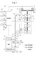
図1は、この実施形態に係る車両(自車両ともいう。)10の概略構成を示すブロック図である。
[Constitution]
FIG. 1 is a block diagram showing a schematic configuration of a vehicle (also referred to as a host vehicle) 10 according to this embodiment.
車両10は、基本的には、エンジンENGと、駆動システム11と、高圧バッテリBAThと、低圧バッテリBATlと、電圧変換器としてのVCU(Voltage Controll Unit)12と、第1インバータINV1と、第2インバータINV2と、電動サーボブレーキESB(Electronic Servo Brake)と、制御装置14と、を備える。
The
駆動システム11は、それぞれベクトル制御される3相の埋込磁石構造の永久磁石同期モータ(回転電機)である第1モータジェネレータMG1及び第2モータジェネレータMG2と、エンジンENGと、駆動力伝達状態切替部15と、減速機Dと、を備える。
The
駆動力伝達状態切替部15は、エンジンENGと減速機Dとを直結させるクラッチ(不図示)と、前記クラッチと減速機Dとの間に介装される変速機又は固定ギヤ段と、を備える。
The driving force transmission
図1中、太い実線は機械連結を示し、二重実線は電力配線を示し、細い実線は制御線(信号線を含む。)を示す。 In FIG. 1, a thick solid line indicates mechanical connection, a double solid line indicates power wiring, and a thin solid line indicates a control line (including a signal line).
この車両10において、駆動力伝達状態切替部15と、該駆動力伝達状態切替部15から両側に延びる機械連結は、エンジンENGを動力源として駆動力伝達状態切替部15を介し減速機Dを通じて車輪(駆動輪)Wを駆動するときのみ使用される。なお、加速時には、エンジンENGと第2モータジェネレータMG2を利用するようにすることもできる。
In this
なお、この発明は、駆動力伝達状態切替部15によって、エンジンENGの動力が車輪(駆動輪)W側とは切離されるとともに、第2モータジェネレータMG2が車輪(駆動輪)Wを駆動する状態で、主として適用される。
In the present invention, the driving force transmission
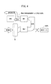
そこで、図2に示すように、煩雑さの回避及び理解の便宜のために、以下、駆動力伝達状態切替部15を描いていない車両10の概略構成を示すブロック図に基づいて構成及び動作を説明する。
Therefore, as shown in FIG. 2, for the sake of avoidance of complexity and convenience of understanding, the configuration and operation will be described based on a block diagram showing a schematic configuration of the
エンジンENGは、第1モータジェネレータMG1を発電機として駆動する。この場合、第1モータジェネレータMG1は、エンジンENGの回転動力により駆動され電力を発生する。 Engine ENG drives first motor generator MG1 as a generator. In this case, first motor generator MG1 is driven by the rotational power of engine ENG to generate electric power.
また、エンジンENGは、車両10の制動時に電動機として動作する第1モータジェネレータMG1により駆動され空回り状態でクランク軸が回転する機械的負荷としても機能する場合がある。
The engine ENG may also function as a mechanical load that is driven by the first motor generator MG1 that operates as an electric motor during braking of the
車両10の駆動用の第2モータジェネレータMG2は、高圧バッテリBATh及び第1モータジェネレータMG1の少なくとも一方からの電力供給によって電動機として動作(力行)し、車両10が走行するためのトルクを発生する。第2モータジェネレータMG2で発生したトルクは、減速機Dを介して車輪Wに駆動力として伝達される。また、第2モータジェネレータMG2は、車両10の制動時には発電機として動作する。
The second motor generator MG2 for driving the
高圧バッテリBAThは、直列に接続された複数の蓄電セルを有し、例えば、100−300[V]の高電圧を供給する。前記蓄電セルは、例えば、リチウムイオン電池やニッケル水素電池のセルである。高圧バッテリBAThは、キャパシタとしてもよい。 The high-voltage battery BATh has a plurality of power storage cells connected in series, and supplies a high voltage of, for example, 100 to 300 [V]. The storage cell is, for example, a lithium ion battery or a nickel metal hydride battery. The high voltage battery BATh may be a capacitor.
コンバータCONVは、高圧バッテリBAThの直流出力電圧を直流のまま降圧するDC/DCコンバータである。低圧バッテリBATlは、コンバータCONVによって降圧された電圧を蓄電し、例えば12[V]の定電圧を補機16に含まれるライト等の電装品18に供給するとともに、制御装置14等の直流電源とされる。
The converter CONV is a DC / DC converter that steps down the direct-current output voltage of the high-voltage battery BATh while maintaining the direct current. The low voltage battery BATl stores the voltage stepped down by the converter CONV, supplies a constant voltage of, for example, 12 [V] to an
VCU12は、高圧バッテリBAThの出力電圧であるV1電圧を、第2モータジェネレータMG2が電動機として動作する際の第2モータジェネレータMG2用の入力電圧であるV2電圧に昇圧する。
The
また、VCU12は、車両10の制動時に第2モータジェネレータMG2が発電機として動作する際の第2モータジェネレータMG2の出力電圧であるV2電圧を降圧し、V1電圧にする。
The
さらに、VCU12は、車両10の制動時に第2モータジェネレータMG2が発電機として動作し、その発電電力により第1インバータINV1を通じて第1モータジェネレータMG1を駆動する際のV2電圧の昇降圧を行う。
Further, the
さらに、VCU12は、エンジンENGの駆動によって第1モータジェネレータMG1が発電し直流に変換されたV2電圧を降圧し、V1電圧にする。
Further, the
つまり、VCU12は、高圧バッテリBathと第1モータジェネレータMG1、及び第2モータジェネレータMG2との間での昇降圧コンバータ(双方向電圧変換器)として機能する。
That is, the
VCU12によって降圧されたV1電圧での電力は、補機16に含まれる電動エアコンプレッサ20の駆動用電力及び/又は高圧バッテリBAThの充電用電力として供給される。
The electric power at the V1 voltage stepped down by the
図3は、高圧バッテリBATh、VCU12、第1インバータINV1、第2インバータINV2、第1モータジェネレータMG1及び第2モータジェネレータMG2の接続関係を示す概略電気回路図である。 FIG. 3 is a schematic electric circuit diagram showing a connection relationship among the high voltage batteries BATh, VCU12, the first inverter INV1, the second inverter INV2, the first motor generator MG1, and the second motor generator MG2.
図3に示すように、VCU12は、平滑コンデンサ、インダクタ及び上下アームの2つのスイッチング素子を備える。VCU12は、高圧バッテリBAThが出力するV1電圧を入力電圧として上下アームの2つのスイッチング素子をオンオフ切り替え動作することによって出力側のV2電圧をV1電圧よりも高い電圧に昇圧する。また、第1インバータINV1又は第2インバータINV2が出力するV2電圧を入力電圧として上下アームの2つのスイッチング素子をオンオフ切り替え動作することによって出力側のV1電圧をV2電圧よりも低い電圧に降圧する。
As shown in FIG. 3, the
なお、VCU12の2つのスイッチング素子がオンオフ切り替え動作しないで、上側スイッチング素子がオン状態、下側スイッチング素子がオフ状態とされたときのV2電圧はV1電圧に等しい。
Note that the V2 voltage when the two switching elements of the
さらに、図3において、第1インバータINV1は、エンジンENGの駆動によって第1モータジェネレータMG1が発電した交流電圧を直流電圧であるV2電圧に変換する。また、第1インバータINV1は、車両10の制動時に第2モータジェネレータMG2で発電され第2インバータINV2によって変換されたV2電圧を交流電圧に変換し3相電流を第1モータジェネレータMG1に供給する場合もある。第2インバータINV2は、V2電圧を交流電圧に変換して3相電流を第2モータジェネレータMG2に供給する(力行)。さらに、第2インバータINV2は、車両10の制動時に第2モータジェネレータMG2が発電した交流電圧をV2電圧に変換する(回生)。
Further, in FIG. 3, the first inverter INV1 converts the AC voltage generated by the first motor generator MG1 by driving the engine ENG into a V2 voltage that is a DC voltage. The first inverter INV1 converts the V2 voltage generated by the second motor generator MG2 and converted by the second inverter INV2 during braking of the
図1及び図2に示した電動サーボブレーキESBは、車両10の運転者によるブレーキペダル30の操作量である踏込量Bpに応じて図示しない電動機によって制御される油圧システムによって車両10を制動する。
The electric servo brake ESB shown in FIGS. 1 and 2 brakes the
制御装置14は、第1インバータINV1、第1モータジェネレータMG1、第2インバータINV2、及び第2モータジェネレータMG2、及びVCU12を含むベクトル制御を行う他、エンジンENG、電動サーボブレーキESB及び補機16の制御を行う。
The
制御装置14による制御の詳細については後述するが、制御装置14は、センサの出力として、ブレーキペダル30の操作量を表す踏込量センサからのブレーキ踏込量Bpの他、アクセルペダル32の操作量を表すアクセル開度センサからのアクセル開度Ap、車速センサ34からの車速Vs、加速度センサ58からの加速度aを取り込む。
Although details of the control by the
また、制御装置14は、センサの出力として、SOC(State Of Charge)センサ35からの高圧バッテリBAThの残容量SOC、スイッチング素子近傍に取り付けられた温度センサ36からの第1インバータINV1の温度Ti1、スイッチング素子近傍に取り付けられた温度センサ37からの第2インバータINV2の温度Ti2、ステータのコイル近傍に取り付けられた温度センサ38からの第1モータジェネレータMG1の温度Tcoil、ステータのコイル近傍に取り付けられた温度センサ39からの第2モータジェネレータMG2の温度Tcoi2、駆動システム11内を循環する冷却用オイル(冷却媒体)の流路に取り付けられた温度センサ40からの冷却媒体の温度Tatfを取り込む。なお、冷却用オイルは、第1及び第2モータジェネレータMG1、MG2を含んで駆動システム11内を冷却する。
Further, the
さらに、制御装置14は、センサの出力として、第1及び第2モータジェネレータMG1、MG2のレゾルバ等のセンサ(不図示)からの回転数・電流・回転角度位置等を取り込む。また、制御装置14は、シフトレバー42の位置を表すシフト位置センサからのシフト位置Ps(例えば、ドライブD位置、ドライブB位置等)を取り込む。
Further, the
[基本的な非効率制御の説明]
ここで、基本的には以上のように構成される車両10の第1モータジェネレータMG1に係わる非効率制御(後述するように、主に正のd軸電流Idをモータジェネレータに印加する制御であって、強め界磁制御ともいう。)の基本的な動作について図4を参照して説明する。
[Description of basic inefficiency control]
Here, basically, inefficient control related to the first motor generator MG1 of the
例えば、車両10の降坂走行時に、アクセルペダル32が開放されると、第2モータジェネレータMG2は力行状態から回生状態に切り替えられる。この場合、第2モータジェネレータMG2は発電機として作動し車両10に制動力(回生制動)を与え、且つ回生電力を発生する。この回生電力は、第2モータジェネレータMG2から第2インバータINV2、及びVCU12を通じて、充電制約のない場合、高圧バッテリBAThに充電され、車両10には、回生ブレーキとしての制動力がかかる。
For example, when the
しかし、高圧バッテリBAThが満充電状態等である充電制約がある場合等には、該高圧バッテリBAThへの回生電力の受け入れが制限される。 However, when there is a charging restriction in which the high voltage battery BATh is in a fully charged state or the like, reception of regenerative power to the high voltage battery BATh is restricted.
そこで、この実施形態では、第2モータジェネレータMG2の回生電力の高圧バッテリBATへの受け入れ(充電)が制限される場合、換言すれば、車両10で余分な電力が発生した場合には、V2電圧により第1インバータINV1を介して第1モータジェネレータMG1を電動機として駆動し、負荷としてのエンジンENGを空回りさせる(エンジンENGは、逆駆動されるという。)。つまり、第1モータジェネレータMG1を通じてエンジンENGを空回りさせるエネルギとして第2モータジェネレータMG2の回生電力が利用される。
Therefore, in this embodiment, when the reception (charging) of the regenerative power of the second motor generator MG2 to the high voltage battery BAT is restricted, in other words, when excess power is generated in the
図4は、車両10の制動時に、第2モータジェネレータMG2が発生した回生電力によって第1モータジェネレータMG1を電動機として駆動しエンジンENGが空回りされる場合のエネルギの流れを示す説明図である。
FIG. 4 is an explanatory diagram showing the flow of energy when the engine ENG is idled by driving the first motor generator MG1 as an electric motor by the regenerative electric power generated by the second motor generator MG2 when the
図4に示すように、第1モータジェネレータMG1を力行運転してエンジンENGを逆駆動する際、第1モータジェネレータMG1に印加するV2電圧をVCU12がV1電圧を昇圧して得、第1モータジェネレータMG1のd軸電流Idが概ね正の値(Id>0)に大きくなるように強め界磁制御を行うことによって、第1モータジェネレータMG1を非効率な動作点で駆動する。
As shown in FIG. 4, when the first motor generator MG1 is power-run to reversely drive the engine ENG, the
なお、通常の界磁制御(図5中、従来効率制御・代表的制御)では、トルクの発生に寄与しないd軸電流Idを負の値(Id<0)とし、電流に対して発生トルクが最大となるようにベクトル制御する最大トルク/電流(Maximum Torque Per Ampere、MTPA)制御としているが、この実施形態では、この最小の電流とは異なる電流値となるように昇圧して第1モータジェネレータMG1を、d軸電流Idが概ね正値{より正確には、図5中、動作点P0でのd軸電流Id0を上回る電流値、Id0<Id(Idは、負値も正値もとる。)}となるように駆動している。 In normal field control (conventional efficiency control / representative control in FIG. 5), the d-axis current Id that does not contribute to the generation of torque is set to a negative value (Id <0), and the generated torque is maximum with respect to the current. The maximum torque / current (Maximum Torque Per Ampere, MTPA) control for vector control is performed, but in this embodiment, the first motor generator MG1 is boosted by increasing the current value to be different from the minimum current. , D-axis current Id is approximately a positive value {more precisely, in FIG. 5, a current value exceeding d-axis current Id0 at operating point P0, Id0 <Id (Id is also a negative value).} It is driven to become.
この場合、第1モータジェネレータMG1に印加するV2電圧を昇圧することによって、第1モータジェネレータMG1の運転可能範囲は拡大する。また、強め界磁制御が行われた第1モータジェネレータMG1では、出力効率が低下して、主に固定子(電機子)コイルの銅損による発熱量が増加する。この発熱量によって、第2モータジェネレータMG2の回生電力の余剰分(余分な電力)を消費する。 In this case, by increasing the voltage V2 applied to first motor generator MG1, the operable range of first motor generator MG1 is expanded. Further, in the first motor generator MG1 in which the strong field control is performed, the output efficiency is lowered, and the amount of heat generated mainly by the copper loss of the stator (armature) coil is increased. Due to the amount of generated heat, a surplus (excess power) of the regenerative power of the second motor generator MG2 is consumed.
なお、以下の説明では、力行運転{第1モータジェネレータMG1の回転方向にトルク(駆動トルク・力行トルク)を発生}する又は回生運転{第1モータジェネレータMG1の回転方向の反対方向にトルク(制動トルク・回生トルク)を発生}する第1モータジェネレータMG1に印加するV2電圧の昇圧と第1モータジェネレータMG1の強め界磁制御をまとめて「非効率制御」という。 In the following description, power running operation {generates torque (drive torque / power running torque) in the rotation direction of the first motor generator MG1} or regenerative operation {torque (braking in the direction opposite to the rotation direction of the first motor generator MG1). Torque / regenerative torque)} is referred to as “inefficiency control”. The boosting of the V2 voltage applied to the first motor generator MG1 and the strong field control of the first motor generator MG1 are collectively referred to.
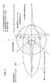
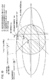
次に、非効率制御を行う場合のdq軸座標(Id−Iq平面ともいう。)上の第1モータジェネレータMG1を代表とするモータジェネレータの動作点及び該モータジェネレータに印加される電圧について図5のId−Iq平面図をも参照して説明する。 Next, the operating point of the motor generator represented by the first motor generator MG1 on the dq axis coordinates (also referred to as Id-Iq plane) when performing inefficiency control and the voltage applied to the motor generator are shown in FIG. This will be described with reference to the Id-Iq plan view.
モータジェネレータの動作点の範囲は、このモータジェネレータに供給可能な最大相電流Iaとモータジェネレータに印加されるV2電圧(インバータの直流端電圧)によって制約される。 The range of the operating point of the motor generator is limited by the maximum phase current Ia that can be supplied to the motor generator and the V2 voltage (DC terminal voltage of the inverter) applied to the motor generator.
モータジェネレータの電流(Id,Iq)の振幅は、最大相電流Iaによって制約されるため、次の(1)式(電流制限円)を満たす必要がある。
Id2+Iq2≦Ia2 …(1)
Since the amplitude of the motor generator current (Id, Iq) is restricted by the maximum phase current Ia, it is necessary to satisfy the following equation (1) (current limit circle).
Id 2 + Iq 2 ≦ Ia 2 (1)
但し、Id:d軸電流、Iq:q軸電流、Ia:最大相電流。なお、Iaは、電流ベクトルIdと電流ベクトルIqとをベクトル合成した電流であるので電流ベクトルIaともいう。 However, Id: d-axis current, Iq: q-axis current, Ia: maximum phase current. Note that Ia is also referred to as a current vector Ia because it is a current obtained by vector synthesis of the current vector Id and the current vector Iq.
また、モータジェネレータの誘起電圧(Vd,Vq)は、次の(2)式で表される。なお、通常(2)式は、マトリクス形式で表される。
Vd=0×Id+(−ωLq)×Iq+0
Vq=(ωLd)×Id+0×Iq+ωψa …(2)
The induced voltage (Vd, Vq) of the motor generator is expressed by the following equation (2). Note that the formula (2) is usually expressed in a matrix format.
Vd = 0 × Id + (− ωLq) × Iq + 0
Vq = (ωLd) × Id + 0 × Iq + ωψa (2)
但し、ω:モータジェネレータの角速度、Lq:q軸インダクタンス、Ld:d軸インダクタンス、ψa:鎖交磁束(磁石磁束)。 Where ω: angular velocity of the motor generator, Lq: q-axis inductance, Ld: d-axis inductance, ψa: interlinkage magnetic flux (magnet magnetic flux).
(2)式より、dq誘起電圧(d軸電機子に生じる誘起電圧Vdとq軸電機子に生じる誘起電圧Vqのベクトル和の大きさ)Voは、次の(3)式で表される。
Vo=(Vd2+Vq2)1/2
=ω{(LdId+ψa)2+(LqIq)2}1/2 …(3)
From the equation (2), the dq induced voltage (the magnitude of the vector sum of the induced voltage Vd generated in the d-axis armature and the induced voltage Vq generated in the q-axis armature) Vo is expressed by the following equation (3).
Vo = (Vd 2 + Vq 2 ) 1/2
= Ω {(LdId + ψa) 2 + (LqIq) 2 } 1/2 (3)
ここで、図2に示したV2電圧の制限電圧をVomとする。制限電圧Vomは、V2電圧によって決まり、関係式は、VCU12のスイッチング制御の変調方式によって決まる定数をkとして、次の(4)式で表される。
Vom=kV2 …(4)
Here, the limit voltage of the V2 voltage shown in FIG. The limiting voltage Vom is determined by the V2 voltage, and the relational expression is expressed by the following expression (4), where k is a constant determined by the modulation method of switching control of the
Vom = kV2 (4)
次の(5)式に示すように、dq誘起電圧Voは、制限電圧Vom以下になっている必要がある。
Vo≦Vom …(5)
As shown in the following equation (5), the dq induced voltage Vo needs to be equal to or lower than the limit voltage Vom.
Vo ≦ Vom (5)
すなわち、(3)式と(5)式とにより、モータジェネレータの動作点の範囲には電圧による制約があるため、次の(6)式(電圧制限楕円)を満たす必要がある。
(LdId+ψa)2+(LqIq)2≦(Vom/ω)2 …(6)
That is, since the range of the operating point of the motor generator is restricted by voltage according to the equations (3) and (5), the following equation (6) (voltage limit ellipse) must be satisfied.
(LdId + ψa) 2 + (LqIq) 2 ≦ (Vom / ω) 2 (6)
上述したように、モータジェネレータの動作の電流による制約は(1)式で表される。 As described above, the restriction due to the current of operation of the motor generator is expressed by equation (1).
図5は、Id−Iq平面(dq座標)を示している。この場合、(1)式は、図5に示すdq座標上の電流制限円(Ia2=Id2+Iq2)の内部領域によって表される。 FIG. 5 shows an Id-Iq plane (dq coordinates). In this case, the expression (1) is represented by the inner region of the current limiting circle (Ia 2 = Id 2 + Iq 2 ) on the dq coordinate shown in FIG.
また、モータジェネレータの動作の電圧による制約は(6)式で表され、(6)式は、図5に示すdq座標上の電圧制限楕円{(LdId+ψa)2+(LqIq)2=(Vom/ω)2}の内部領域によって表される。モータジェネレータに供給可能な電流の範囲は、(1)式及び(6)式を満たす範囲であり、この範囲は図5にハッチングした範囲で示される。
一方、モータジェネレータのトルクTは、次の(7)式で表される。
T=Pn{ψaIq+(Ld−Lq)IdIq} …(7)
Further, the restriction due to the voltage of the operation of the motor generator is expressed by the equation (6). The equation (6) is a voltage limit ellipse {(LdId + ψa) 2 + (LqIq) 2 = (Vom / ω) 2 } is represented by the inner region. The range of the current that can be supplied to the motor generator is a range that satisfies the formulas (1) and (6), and this range is indicated by the hatched range in FIG.
On the other hand, the torque T of the motor generator is expressed by the following equation (7).
T = Pn {ψaIq + (Ld−Lq) IdIq} (7)
但し、Pn:モータジェネレータの極対数。右辺第1項は永久磁石によるトルク、右辺第2項はリラクタンストルクである。 Where Pn is the number of pole pairs of the motor generator. The first term on the right side is the torque by the permanent magnet, and the second term on the right side is the reluctance torque.
この(7)式をIqについて解いた等トルクライン(等トルク曲線、定トルクライン、又は定トルク曲線ともいう。)を表す式は、次の(8)式で表される。
Iq=T/[Pn{ψaIq+(Ld−Lq)Id}] …(8)
An equation representing an equal torque line (also referred to as an equal torque curve, a constant torque line, or a constant torque curve) obtained by solving the equation (7) for Iq is represented by the following equation (8).
Iq = T / [Pn {ψaIq + (Ld−Lq) Id}] (8)
この(8)式は、Id=ψa/(Lq−Ld)、Iq=0を漸近線とする双曲線(図5中の等トルクラインTの力行側と回生側の曲線)を表す。 This equation (8) represents a hyperbola (curve on the power running side and regeneration side of the equal torque line T in FIG. 5) having Id = ψa / (Lq−Ld) and Iq = 0 asymptotic lines.
ところで、非効率制御を行わないモータジェネレータの動作点の制御では、例えば、電流に対するトルクが最大となる最大トルク/電流制御(動作点における定トルク曲線の接線と電流ベクトルが直交する制御)や、銅損だけでなく鉄損等を考慮した損失が最小となる最大効率制御(動作点は最大トルク制御よりも進み位相、すなわちd軸電流Idを負の方向へ移動させることが多い。)が行われる。 By the way, in the control of the operating point of the motor generator that does not perform inefficiency control, for example, the maximum torque / current control that maximizes the torque with respect to the current (control in which the tangent of the constant torque curve at the operating point and the current vector are orthogonal), Maximum efficiency control that minimizes not only copper loss but also iron loss and the like (the operating point is more advanced than maximum torque control, that is, the d-axis current Id is often moved in the negative direction) is performed. Is called.
図5に示す例では、動作点(交点ともいう。)P0等、代表的な従来効率制御{最大トルク/電流(Maximum Torque Per Ampere、MTPA)制御}の曲線(動作点)上でモータジェネレータを駆動する。 In the example shown in FIG. 5, the motor generator is set on a curve (operating point) of typical conventional efficiency control {Maximum Torque Per Ampere (MTPA) control} such as an operating point (also referred to as an intersection) P0. To drive.
これに対し、この実施形態に行う非効率制御では、その図5に示すように、モータジェネレータのd軸電流Idが、例えば動作点(交点)P4の値のように正の値に大きくなるように強め界磁制御を行う。この強め界磁制御を行うために、モータジェネレータに印加するV2電圧を上げる必要がある。モータジェネレータに印加するV2電圧を上げることによってモータジェネレータの電流Ia(Id,Iq)の振幅が増大し、モータジェネレータの動作点を移動させることができる。モータジェネレータの負荷であるエンジンENGの逆駆動に要するトルクは、エンジン回転数や温度等に伴って変化するオイル粘度等に応じたフリクションによって決まるが、定性的には、当該トルクが小さいときは定トルク曲線が漸近線に近づくため、d軸電流Idを正の方向に移動させ易い。 On the other hand, in the inefficiency control performed in this embodiment, as shown in FIG. 5, the d-axis current Id of the motor generator is increased to a positive value, for example, the value of the operating point (intersection point) P4. Strong field control is performed. In order to perform this strong field control, it is necessary to increase the V2 voltage applied to the motor generator. By increasing the voltage V2 applied to the motor generator, the amplitude of the current Ia (Id, Iq) of the motor generator is increased, and the operating point of the motor generator can be moved. The torque required to reversely drive the engine ENG, which is the load of the motor generator, is determined by the friction according to the oil viscosity, etc., which changes with the engine speed, temperature, etc., but qualitatively, it is constant when the torque is small. Since the torque curve approaches the asymptotic line, it is easy to move the d-axis current Id in the positive direction.
また、V2電圧の制限電圧Vomが大きく、モータジェネレータの角速度ωが小さいときには、(6)式の定電圧楕円の面積が大きくなるため、モータジェネレータの電流Ia(Id,Iq)の振幅を増大させ易い。 Further, when the limit voltage Vom of the V2 voltage is large and the angular velocity ω of the motor generator is small, the area of the constant voltage ellipse in the equation (6) becomes large, so that the amplitude of the motor generator current Ia (Id, Iq) is increased. easy.
このため、V2電圧の制限電圧Vom及びモータジェネレータの角速度ωを適切に制御すれば、モータジェネレータの非効率制御を効率的に行うことができることが分かる。 Therefore, it can be seen that the inefficiency control of the motor generator can be efficiently performed by appropriately controlling the limit voltage Vom of the V2 voltage and the angular velocity ω of the motor generator.
図5において、モータジェネレータの力行側での非効率制御(Id>Id0、Iq>0)下でのV2電圧の昇圧前最大相電流Imaxは、電圧制限楕円と等トルクラインとの交点(動作点)P1で制限される。 In FIG. 5, the maximum phase current Imax before boosting the V2 voltage under inefficient control (Id> Id0, Iq> 0) on the power running side of the motor generator is the intersection of the voltage limit ellipse and the equal torque line (operating point). ) Limited by P1.
なお、モータジェネレータの回生側での非効率制御(Id>Id0、Iq<0)におけるV2電圧の昇圧前最大相電流Imaxは、電圧制限楕円と等トルクラインとの交点P1´で制限される。 Note that the maximum phase current Imax before boosting of the V2 voltage in the inefficient control (Id> Id0, Iq <0) on the regeneration side of the motor generator is limited at the intersection P1 ′ between the voltage limit ellipse and the equal torque line.
[非効率制御の詳細な動作説明]
次に車両10における要求回生電力Pregが高圧バッテリBAThの受け入れ可能電力より大きい場合における非効率制御(非効率運転)の具体例について図6のフローチャートを参照して詳細に説明する。
[Detailed operation description of inefficient control]
Next, a specific example of inefficiency control (inefficiency operation) when the required regenerative power Preg in the
ステップS1にて、制御装置14は、第2モータジェネレータMG2の要求回生電力Pregを算出する。要求回生電力Pregは、公知のように、道路の勾配(勾配検知センサ又は推定可能)、シフトレバー42のシフト位置Ps(例えば、ドライブD位置、ドライブB位置等)、アクセルペダル32の開度Ap(ここでは、開度Ap=0(アクセルペダル32g開放状態))、車速センサ34の車速Vs、及びブレーキペダル30の踏込量Bpに基づき、目標減速Gが算出され、この目標減速Gに基づき要求回生電力Pregが算出される。
In step S1,
ここでは、車速Vsが概ね一定になるように、降坂勾配に応じて要求回生電力Pregが算出されるものとする。 Here, it is assumed that the required regenerative power Preg is calculated according to the downhill slope so that the vehicle speed Vs is substantially constant.
次いで、ステップS2にて、高圧バッテリBAThの受け入れ可能電力(バッテリ受け入れ可能電力)Pbatinを算出する。 Next, in step S2, an acceptable power (battery acceptable power) Pbatin of the high voltage battery BATh is calculated.
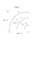
図7の特性(マップ)に示すように、バッテリ受け入れ可能電力Pbatinは、SOCセンサ35により検出される残容量SOCが100[%]であれば、Pbatin=0[kW]である。
As shown in the characteristic (map) of FIG. 7, the battery acceptable power Pbatin is Pbatin = 0 [kW] when the remaining capacity SOC detected by the
残容量SOCが100[%]未満であれば、残容量SOCと、バッテリ温度Tbat(例えば、図示するように、−30[℃]程度から+50[℃]程度)とを入力値とした特性(マップ)を参照して取得する。この特性は、予め作成され、同一の残容量SOCにおいて、バッテリ温度Tbatが高い程、バッテリ受け入れ可能電力Pbatinが大きくなる特性になっている。同様に、例えば、同一のバッテリ温度Tbatにおいて、残容量SOCが低い程、バッテリ受け入れ可能電力Pbatinが大きくなる特性になっている。 If the remaining capacity SOC is less than 100 [%], the remaining capacity SOC and the battery temperature Tbat (for example, about −30 [° C.] to about +50 [° C.] as shown in the figure) are input characteristics ( Get by referring to the map). This characteristic is created in advance, and has the characteristic that the battery acceptable power Pbatin increases as the battery temperature Tbat increases in the same remaining capacity SOC. Similarly, for example, at the same battery temperature Tbat, the lower the remaining capacity SOC, the higher the battery acceptable power Pbatin.
次に、ステップS3にて、補機消費電力Pauxを算出する。補機消費電力Pauxは、電動エアコンプレッサ20の消費電力と、コンバータCONVの消費電力と、電装品18の消費電力との和により算出される。
Next, in step S3, auxiliary machine power consumption Paux is calculated. The auxiliary machine power consumption Paux is calculated by the sum of the power consumption of the
次いで、ステップS4にて、非効率運転の実施が必要か否かを判断する。この場合、要求回生電力Pregが、バッテリ受け入れ可能電力Pbatinと補機消費電力Pauxとにより消費可能であれば(Preg≦Pbatin+Paux)、非効率運転を行わなくても車両10で消費(充電を含む。)できるので、非効率運転フラグFiをリセットにする(Fi←0)。その一方、要求回生電力Pregが、受け入れ可能電力Pbatinと補機消費電力Pauxとの合成消費電力より大きい(Preg>Pbatin+Paux)場合には、非効率運転を行う必要があると判断し、非効率運転フラグFiをセットにする(Fi←1)。
Next, in step S4, it is determined whether or not it is necessary to perform inefficient operation. In this case, if the required regenerative power Preg can be consumed by the battery acceptable power Pbatin and the auxiliary machine power consumption Paux (Preg ≦ Pbatin + Paux), it is consumed (including charging) in the
次に、ステップS5にて、非効率運転フラグFiがセットされている(Fi=1)か、否(Fi=0)かを判断する。 Next, in step S5, it is determined whether the inefficient operation flag Fi is set (Fi = 1) or not (Fi = 0).
非効率運転フラグFiがセットされていない(Fi=0)場合(ステップS5:NO)には、第2モータジェネレータMG2の要求回生電力Pregを第1モータジェネレータMG1(ここでは、単に電動機ともいう。)の非効率領域で消費する必要はない。そのため、ステップS6にて、電動機非効率領域消費電力Pineをゼロ(Pine←0)として、ステップS1に戻る。 When the inefficient operation flag Fi is not set (Fi = 0) (step S5: NO), the required regenerative power Preg of the second motor generator MG2 is also referred to as the first motor generator MG1 (here, simply referred to as an electric motor). There is no need to consume in inefficient areas. Therefore, in step S6, the motor inefficient area power consumption Pine is set to zero (Pine ← 0), and the process returns to step S1.
非効率運転フラグFiがセットされている(Fi=1)場合(ステップS5:YES)には、ステップS7にて、電動機非効率領域消費電力Pineを算出するとともに、電動サーボブレーキ分担電力Pesvを算出する。 When the inefficient operation flag Fi is set (Fi = 1) (step S5: YES), in step S7, the motor inefficient area power consumption Pine is calculated and the electric servo brake shared power Pesv is calculated. To do.
図8は、ステップS7の詳細フローチャートである。 FIG. 8 is a detailed flowchart of step S7.
ステップS7aにて、要求回生電力Pregから算出した必要相電流値を要求相電流Ireqとする。 In step S7a, the required phase current value calculated from the required regenerative power Preg is set as the required phase current Ireq.
図5に示すように、要求相電流Ireqは、昇圧前最大相電流Imax(=Ia)より大きいので、ステップS7bにて、要求相電流Ireqを確保できるように、VCU12にてV2電圧に係る制限電圧Vomを制限電圧V´omへ昇圧し、電圧制限楕円を次の(6´)式に示すように拡大する。
(LdId+ψa)2+(LqIq)2≦(V´om/ω)2 …(6´)
As shown in FIG. 5, since the required phase current Ireq is larger than the maximum phase current Imax (= Ia) before boosting, the
(LdId + ψa) 2 + (LqIq) 2 ≦ (V′om / ω) 2 (6 ′)
次いで、ステップS7cにて、昇圧後電動機非効率領域での限界消費電力を電動機非効率領域消費電力Pineとする。 Next, in step S7c, the limit power consumption in the motor inefficiency region after boosting is set as the motor inefficiency region power consumption Pine.
次に、ステップS7dにて、要求相電流Ireqと電流制限円の昇圧後相電流(電流制限円相電流ともいう。)I´maxとの大きさ(絶対値)を比較し、|Ireq|>|I´max|であるか否かを判断する。 Next, in step S7d, the magnitude (absolute value) of the required phase current Ireq and the post-boosting phase current (also referred to as current limiting circular phase current) I′max of the current limiting circle is compared, and | Ireq |> It is determined whether or not | I′max |.
要求相電流Ireqの大きさが電流制限円相電流I´maxの大きさよりも小さい(ステップS7d:NO)場合(等しい場合までを含む)には、電動サーボブレーキESBでの分担電力は不要であるので、ステップS7eにて、電動サーボブレーキ分担電力1←0に設定する。
When the magnitude of the requested phase current Ireq is smaller than the magnitude of the current limiting circular phase current I′max (step S7d: NO) (including the case where they are equal), the electric power shared by the electric servo brake ESB is unnecessary. Therefore, in step S7e, the electric servo brake shared
この場合、図9に示すように、(6)式で示される電圧制限楕円を、要求相電流Ireq=I´maxが確保できるようVCU12を昇圧(制限電圧Vomが制限電圧V´omとなるようにV2電圧を昇圧)することで、(6´)式で示されるVCU昇圧後電圧制限楕円に拡大する。
In this case, as shown in FIG. 9, the voltage limiting ellipse expressed by the equation (6) is boosted to increase the
このとき、要求回生電力Pregを第1モータジェネレータMG1の非効率制御により熱として消費できるよう、昇圧前最大相電流Imaxの交点P1を等トルクライン上で昇圧後最大相電流I´maxの交点P2(=P4)まで、さらなる強め界磁方向(正のd軸電流の値をさらに大きくする方向)に変更する。 At this time, the intersection point P1 of the maximum phase current Imax after boosting is set on the equal torque line so that the required regenerative power Preg can be consumed as heat by the inefficient control of the first motor generator MG1. Until (= P4), the magnetic field is further changed to the strong field direction (the direction in which the value of the positive d-axis current is further increased).
その一方、ステップS7dの判断にて、要求相電流Ireqの大きさが電流制限円相電流I´maxの大きさよりも大きい(ステップS7d:YES)場合には、電動サーボブレーキESBでの分担電力が必要となる。そのため、ステップS7fにて、電動サーボブレーキ分担電力1を、Ra(Ireq2−I´max2)に設定する。
On the other hand, if it is determined in step S7d that the required phase current Ireq is larger than the current-limited circular phase current I'max (step S7d: YES), the electric power shared by the electric servo brake ESB is Necessary. Therefore, in step S7f, the electric servo brake shared
この場合、図10に示すように、(6´)式で示されるVCU昇圧後電圧制限楕円が、VCU12の能力限界である電流制限円と交差する範囲まで拡大される。このとき、要求回生電力Pregを第1モータジェネレータMG1の非効率制御により熱として消費できるよう、昇圧前最大相電流Imaxの交点P1を等トルクライン上で昇圧後最大相電流I´maxの交点P2(=P4)までさらなる強め界磁方向(正のd軸電流の値をさらに大きくする方向)に変更する。ここで、交点P2から点P4までの要求電力分Ra(Ireq2−I´max2)を電動サーボブレーキ分担電力1とし、電動サーボブレーキESBで消費させる。この結果、第2モータジェネレータMG2の回生制動力に対し、電動サーボブレーキESBによる制動力が加算される。
In this case, as shown in FIG. 10, the post-boost voltage limit ellipse expressed by the equation (6 ′) is expanded to a range that intersects the current limit circle that is the capability limit of the
次に、ステップS17にて、電圧制限楕円を拡大した電動機非効率運転を行う際、又は行った結果として、第1モータジェネレータMG1の制限温度に達しているか否かを熱害条件として処理判断する。 Next, in step S17, whether or not the motor inefficient operation with the expanded voltage limit ellipse is performed or as a result of the determination is made as a heat damage condition as a heat damage condition. .
図11は、ステップS17の詳細フローチャートである。 FIG. 11 is a detailed flowchart of step S17.
ステップS17aにて第1モータジェネレータMG1の電機子コイルに具備されたサーミスタ等の温度センサ38(図2)により電動機コイル温度Tcoilを取得する。 In step S17a, the motor coil temperature Tcoil is acquired by the temperature sensor 38 (FIG. 2) such as a thermistor provided in the armature coil of the first motor generator MG1.
さらに、ステップS17bにて第1モータジェネレータMG1を冷却するオイルの温度である冷却媒体温度Tatfを温度センサ40から取得する。
Further, a cooling medium temperature Tatf, which is the temperature of the oil that cools the first motor generator MG1, is acquired from the
次いで、ステップS17cにて、電動機コイル温度Tcoilが管理温度である閾値温度Th1より小さく(Tcoil<Tth1)、且つ冷却媒体温度Tatfが管理温度である閾値温度Th2より小さいか(Tatf<Th2)否かを判断する。 Next, in step S17c, whether or not the motor coil temperature Tcoil is smaller than the threshold temperature Th1 that is the management temperature (Tcoil <Tth1), and the coolant temperature Tatf is smaller than the threshold temperature Th2 that is the management temperature (Tatf <Th2). Judging.
ステップS17cの判断が肯定的(Tcoil<Th1、且つTatf<Th2)である(ステップS17c:YES)場合には、第1モータジェネレータMG1は熱害にさらされないものと判断し、ステップS17dにて、熱害フラグFheatをリセット(Fheat←0)してステップS1にもどる。 If the determination in step S17c is affirmative (Tcoil <Th1 and Tatf <Th2) (step S17c: YES), it is determined that the first motor generator MG1 is not exposed to heat damage, and in step S17d, The heat damage flag Fheat is reset (Fheat ← 0), and the process returns to step S1.
その一方、ステップS17cでの温度の判断中、少なくとも一方の温度の判断が否定的になって、ステップS17cの判断が否定的となった(ステップS17c:NO)場合には、第1モータジェネレータMG1を熱害から守る必要があるので、まず、ステップS17eにて、熱害フラグFheatをセット(Fheat←1)する。 On the other hand, during the determination of the temperature in step S17c, if the determination of at least one temperature is negative and the determination of step S17c is negative (step S17c: NO), the first motor generator MG1. First, in step S17e, the heat damage flag Fheat is set (Fheat ← 1).
次いで、ステップS17fにて、電圧制限楕円に係る熱害条件Vomの条件変更を行い、ステップS18にて、さらに、電動サーボブレーキESBの総分担電力を算出する。 Next, in step S17f, the heat damage condition Vom related to the voltage limit ellipse is changed, and in step S18, the total electric power shared by the electric servo brake ESB is calculated.
図13を参照してステップS17f及びステップS18の処理を説明する。 The process of step S17f and step S18 is demonstrated with reference to FIG.
Fheat=1である熱害条件が成立した場合、次の(5´´)式に示すように、V´omをVheatomまで戻して、すなわち、V2電圧を低下させて、電動機非効率領域を、高温時においても運転可能な電圧制限楕円まで縮小する。この場合、電動機軸端要求トルク特性上の等トルクラインをトレースしながら相電流Imaxを交点P5まで小さくする。 When the heat damage condition of Fheat = 1 is satisfied, as shown in the following equation (5 ″), V′om is returned to V heat om, that is, the V2 voltage is decreased to reduce the motor inefficiency region. Is reduced to a voltage-limiting ellipse that can be operated even at high temperatures. In this case, the phase current Imax is reduced to the intersection point P5 while tracing the equal torque line on the motor shaft end required torque characteristic.
(LdId+ψa)2+(LqIq)2≦(Vheatom/ω)2 …(5´´) (LdId + ψa) 2 + (LqIq) 2 ≦ (V heat om / ω) 2 (5 ″)
この場合、ステップS18にて電動サーボブレーキESBの総分担電力Pesballを算出する。 In this case, the total shared electric power Pesball of the electric servo brake ESB is calculated in step S18.
図12は、ステップS18の詳細フローチャートである。 FIG. 12 is a detailed flowchart of step S18.
ステップS18aにて、熱害フラグFheatがFheat=1であるか否(Fheat=0)かをステップS17cで説明した内容で再判断し、熱害フラグFheatがFheat=0であるときには、熱害条件がクリアされたので、相電流Iheatmaxを等トルクライン上で相電流Iaを相電流I´maxまで戻し、動作点(交点)P5を動作点(交点)P3にする。これにより、ステップS18bに示すように、電動サーボブレーキESBの総分担電力Pesball(電動サーボフレーキ分担電力ALLという。)を、ステップS7fで算出した電動サーボブレーキESBの分担電力1までもどすことができる。
In step S18a, it is determined again whether or not the heat damage flag Fheat is Fheat = 1 (Fheat = 0) based on the contents described in step S17c. When the heat damage flag Fheat is Fheat = 0, the heat damage condition is satisfied. Is cleared, the phase current I heat max is returned to the phase current I′max on the equal torque line, and the operating point (intersection point) P5 is set to the operating point (intersection point) P3. As a result, as shown in step S18b, the total shared power Pesball (referred to as electric servo flake shared power ALL) of the electric servo brake ESB can be returned to the shared
その一方、ステップS18aの判断にて、熱害フラグFheatがFheat=1であるときには、熱害条件がクリアされていないので、相電流Iheatmaxの動作点(交点)P5にて、電動サーボブレーキESBの総分担電力Pesballを、動作点(交点)P3から動作点(交点)P4間の分であるステップS7fで算出した電動サーボブレーキ分担電力1=Ra(Ireqmax2−I´max2)と、動作点(交点)P3から動作点(交点)P5までの電動サーボブレーキ分担電力=Ra(I´max2−Iheatmax2)との合成電力を電動サーボブレーキESBで分担し消費させる。
このようにして、第1モータジェネレータMG1を熱害から守ることができる。
なお、上述したステップ17では、熱害条件が成立した場合に電圧制限楕円を縮小することで、電動機の運転点をP3からP5まで移行させたが、電圧制限楕円は縮小させずに、すなわち、V2電圧(昇圧電圧)を低下させずに、電動機の運転点をP3からP5まで移行させることも可能である。
On the other hand, if it is determined in step S18a that the heat damage flag Fheat is Fheat = 1, since the heat damage condition is not cleared, the electric servo brake is operated at the operating point (intersection) P5 of the phase current I heat max. The electric servo brake shared
In this way, the first motor generator MG1 can be protected from heat damage.
In
[実施形態のまとめ及び変形例]
この実施形態に係る車両10は、蓄電装置としての高圧バッテリBAThと、直流と交流の両方向に変換可能な駆動装置としての第1及び第2インバータINV1、INV2と、前記駆動装置としての第1及び第2インバータINV1、INV2の交流側に接続されるとともに、出力軸が負荷(第1インバータINV1の負荷としてのエンジンENG及び/又は第2インバータINVの負荷としての車輪W)に接続される回転電機としての第1モータジェネレータMG1及び/又は第2モータジェネレータMG2)と、低圧側(V1電圧側)が高圧バッテリBAThに接続され高圧(V2電圧)側が第1及び第2インバータINV1、INV2の直流側に接続され、高圧バッテリBAThのV1電圧を昇圧してV2電圧とし、該昇圧電圧であるV2電圧を、前記第1及び第2インバータINV1、INV2を通じてそれぞれ第1及び第2モータジェネレータMG1、MG2に印加する電圧変換器としてのVCU12と、前記第1及び第2インバータINV1、INV2、前記第1及び第2モータジェネレータMG1、MG2及び前記VCU12を制御する制御装置14と、を備える。
[Summary of Embodiment and Modifications]
The
上述した図13は、全体動作の説明に供されるId−Iq平面図である。
制御装置14は、該車両10で余分な電力が発生した場合、例えば、第2モータジェネレータMG2の回生電力Pregの一部又は全部が余剰になって補機16での消費を行っても、さらに残容量SOCが100[%]の高圧バッテリBAThへの充電ができない場合、VCU12による前記昇圧電圧であるV2電圧(制限電圧Vom)を、第1モータジェネレータMG1が所定の駆動力を発生させるための最も小さな電流値(図13の「従来効率制御」での動作点P0での電流値)とは異なる電流値{図13中、動作点P0におけるd軸電流値(d軸閾値電流値という。)Id0より大きな電流値(Id>Id0)}となるように昇圧(例えば、制限電圧V´om、図13中、交点P3)することで第1モータジェネレータMG1の運転範囲を拡大する。
FIG. 13 described above is an Id-Iq plan view for explaining the overall operation.
If excessive power is generated in the
そして、拡大した前記運転範囲で該第1モータジェネレータMG1を駆動することで、前記余分な電力、例として第2モータジェネレータMG2の回生電力Pregの一部又は全部を第1モータジェネレータMG1により消費させることができる。 Then, by driving the first motor generator MG1 in the expanded operating range, the first motor generator MG1 consumes part or all of the extra power, for example, the regenerative power Preg of the second motor generator MG2. be able to.
この消費中に、第1モータジェネレータMG1の温度、ここでは、銅損で温度上昇するコイル温度Tcoil又は第1インバータINV1の温度Ti1あるいは冷却媒体の温度Tatfがそれぞれに対応して予め定められている閾値温度Tthを上回ったとき、前記昇圧電圧であるV2電圧を小さくして第1モータジェネレータMG1の運転範囲を縮小し、第1モータジェネレータMG1が消費する電力を小さくする{例えば、制限電圧Vheatom、図13中、動作点(交点)P5}。 During this consumption, the temperature of the first motor generator MG1, in this case, the coil temperature Tcoil that rises due to copper loss, the temperature Ti1 of the first inverter INV1, or the temperature Tatf of the cooling medium is predetermined. When the temperature exceeds the threshold temperature Tth, the voltage V2 that is the boosted voltage is reduced to reduce the operating range of the first motor generator MG1, and the power consumed by the first motor generator MG1 is reduced {eg, the limit voltage V heat om, operating point (intersection point) P5} in FIG.
このように制御することで、車両10内で発生し、補機16や高圧バッテリBAThで消費乃至充電できない余分な電力を消費することができ、第1モータジェネレータMG1又は第1インバータINV1の過熱を防止することができる。
By controlling in this way, it is possible to consume extra power that is generated in the
なお、V2電圧を昇圧することで第1モータジェネレータMG1の運転範囲を拡大する際には、等トルクライン上でd軸電流Idを大きくし、前記昇圧電圧であるV2電圧を小さくする際には、前記等トルクライン上でd軸電流Idを小さくするようにしたので、第1モータジェネレータMG1の軸端トルク(出力軸に生じるトルク)を一定に保持しながら、第1モータジェネレータMG1での消費電力を可変することができる。 When the operating range of the first motor generator MG1 is expanded by boosting the V2 voltage, the d-axis current Id is increased on the equal torque line, and the V2 voltage that is the boosted voltage is decreased. Since the d-axis current Id is reduced on the equal torque line, the consumption by the first motor generator MG1 is maintained while keeping the shaft end torque (torque generated on the output shaft) of the first motor generator MG1 constant. Electric power can be varied.
特に、d軸電流Idが正値となる強め界磁制御(非効率制御)の場合には、第1モータジェネレータMG1の温度上昇に伴う永久磁石の減磁を防止することができるという派生的な効果も達成される。つまり、強め界磁制御(非効率制御)であるので永久磁石が高温となっても、永久磁石に反磁界を与えることがなく、着磁する方向の磁界を与えるため、磁石減磁の耐性が向上する。 In particular, in the case of strong field control (inefficiency control) in which the d-axis current Id is a positive value, there is also a derivative effect that the demagnetization of the permanent magnet accompanying the temperature increase of the first motor generator MG1 can be prevented. Achieved. That is, since strong field control (inefficiency control) is performed, even if the permanent magnet becomes high temperature, no demagnetizing field is applied to the permanent magnet, and a magnetic field in the direction of magnetization is applied, so that the resistance to magnet demagnetization is improved. .
その上、強め界磁制御(非効率制御)であるので、図示しないロータの永久磁石とステータの電機子との吸引力(磁気拘束力)が高まる結果、ロータの回転方向及びロータの軸方向の磁気拘束力が高まり、第1モータジェネレータMG1のNV特性が向上するという派生的な効果も奏される。 In addition, because of strong field control (inefficiency control), the attractive force (magnetic restraint force) between the permanent magnet of the rotor (not shown) and the armature of the stator increases, resulting in magnetic restraint in the rotational direction of the rotor and in the axial direction of the rotor. The derivative effect that the force is increased and the NV characteristic of the first motor generator MG1 is improved is also exhibited.
この場合において、自車両10が発生する余分な電力が制動用の回生電力Pregである場合に、回生電力Pregによる制動力を第1モータジェネレータMG1の力行による電力消費で担保し、それでも足りない分を機械ブレーキ、この実施形態では、電動サーボブレーキESBで補うようにしているので、制動力は確保される。また、等トルクライン上で制御しているので、車両挙動の変化が抑制される。
In this case, when the surplus power generated by the
車両10は、ハイブリッド車両であり、この実施形態によれば、機械ブレーキの介入を最小限に抑制することができ、機械ブレーキの摩擦材を長期間使用できるようになる。使用期間が通常と同じでよいならば、機械ブレーキの摩擦材を小さくすることができる。
The
図14を参照して、この実施形態の作用を分かり易く説明する。
高圧バッテリBAThの充電が可能である場合、車輪Wへの制動力は、第2モータジェネレータMG2の回生電力及び電動サーボブレーキESBの熱発生(電動サーボブレーキ分担電力1)により担保され、回生電力は高圧バッテリBAThに充電される。エンジンENGにより回転される第1モータジェネレータMG1の発電電力も高圧バッテリBAThに充電される(図14中、最上段の図)。
With reference to FIG. 14, the operation of this embodiment will be described in an easily understandable manner.
When the high-voltage battery BATh can be charged, the braking force applied to the wheels W is secured by the regenerative power of the second motor generator MG2 and the heat generation of the electric servo brake ESB (electric servo brake shared power 1). The high voltage battery BATh is charged. The generated power of the first motor generator MG1 rotated by the engine ENG is also charged in the high voltage battery BATh (the uppermost diagram in FIG. 14).
高圧バッテリBAThの充電が制約されるとき(高圧バッテリBAThが満充電)、第1モータジェネレータMG1等の非熱害時には、第2モータジェネレータMG2の回生電力Pregにより、第1モータジェネレータMG1を非効率領域の等トルクライン上で力行運転することでエンジンENGを空回しするとともに、回生電力Pregを第1モータジェネレータMG1の非効率領域で熱に変換する(図13の交点P2=P3)。この場合、電動サーボブレーキESBの熱発生は変化しない(図14中、中段の図)。 When charging of the high-voltage battery BATh is restricted (the high-voltage battery BATh is fully charged), the first motor generator MG1 is inefficient due to the regenerative power Preg of the second motor generator MG2 when the first motor generator MG1 or the like is not thermally damaged. The engine ENG is idled by performing a power running operation on the equal torque line in the region, and the regenerative power Preg is converted into heat in the inefficient region of the first motor generator MG1 (intersection P2 = P3 in FIG. 13). In this case, the heat generation of the electric servo brake ESB does not change (the middle diagram in FIG. 14).
その一方、高圧バッテリBAThの充電が制約されるとき(高圧バッテリBAThが満充電)であって、第1モータジェネレータMG1等の熱害時には、上記実施形態で説明したように、回生電力Pregにより、第1モータジェネレータMG1を非効率領域の等トルクライン上で力行運転することでエンジンENGを空回しするとともに、回生電力Pregを第1モータジェネレータMG1の非効率領域で熱に変換するが、ハッチング領域で示すように非効率領域での消費電力を減少させる(図13の交点P5)。その分、電動サーボブレーキESBの分担分を大きくするので、電動サーボブレーキESBでの熱発生は大きくなる(図14中、下段の図)。 On the other hand, when charging of the high-voltage battery BATh is restricted (the high-voltage battery BATh is fully charged), and when the first motor generator MG1 or the like is damaged by heat, as described in the above embodiment, the regenerative power Preg The engine ENG is idled by powering the first motor generator MG1 on the equal torque line in the inefficient region, and the regenerative power Preg is converted into heat in the inefficient region of the first motor generator MG1, but the hatching region As shown, the power consumption in the inefficient region is reduced (intersection P5 in FIG. 13). Accordingly, since the share of the electric servo brake ESB is increased, heat generation in the electric servo brake ESB is increased (the lower diagram in FIG. 14).
このように上記した実施形態によれば、第2モータジェネレータMG2又は第2インバータINV2を構成する要素(コンポーネント)の温度が管理温度以上になったと判断された場合には、VCU12の昇圧電圧であるV2電圧を下げ、モータジェネレータMG2の非効率領域の運転領域上限を小さくするようにしている。
As described above, according to the above-described embodiment, when it is determined that the temperature of the element (component) constituting the second motor generator MG2 or the second inverter INV2 is equal to or higher than the management temperature, the boosted voltage of the
このように構成することで、新規なデバイスを追加することなく(構成の変更なく)、制御の変更のみで(コストの増加なく)、過昇温による第2モータジェネレータMG2及び第2インバータINV2の故障を未然に防止することができる。しかも車両10の挙動に与える影響を抑制することができる。
With this configuration, the second motor generator MG2 and the second inverter INV2 caused by excessive temperature rise can be obtained without adding a new device (without changing the configuration) and only changing the control (without increasing the cost). Failure can be prevented in advance. In addition, the influence on the behavior of the
[変形例]
図15は、変形例の車両10Aの概略構成を示すブロック図である。
[Modification]
FIG. 15 is a block diagram showing a schematic configuration of a modified
この変形例の車両10Aは、いわゆる電気自動車である。この車両10Aにおいて、例えば、長い下り坂を走行中(降坂中)に、第2モータジェネレータMG2の回生電力Pregが、余剰となり余分な電力が発生した場合に、図5に示した回生側(Id>0、Iq<0)の等トルクライン(回生)上の非効率領域(Id>Id0、特にId>0)で第2モータジェネレータMG2を動作させることで、実施形態で説明したのと同様に、前記余分な電力を消費させることができる。
なお、回生側においてもV2電圧を昇圧し、拡大した運転範囲で第2モータジェネレータMG2の回生時の非効率制御を行ってもよい。
The
Note that, on the regeneration side, the V2 voltage may be boosted, and inefficiency control during regeneration of the second motor generator MG2 may be performed within the expanded operating range.
なお、この発明は、上述の実施形態に限らず、この明細書の記載内容に基づき、種々の構成を採り得ることはもちろんである。 Note that the present invention is not limited to the above-described embodiment, and it is needless to say that various configurations can be adopted based on the contents described in this specification.
10、10A…車両(自車両) 11…駆動システム
12…VCU 14…制御装置
ENG…エンジン ESB…電動サーボブレーキ
INV1…第1インバータ INV2…第2インバータ
MG1…第1モータジェネレータ MG2…第2モータジェネレータ
DESCRIPTION OF
Claims (8)
直流と交流の両方向に変換可能な駆動装置と、
前記駆動装置の交流側に接続されるとともに、出力軸が負荷に接続される回転電機と、
低圧側が前記蓄電装置に接続され高圧側が前記駆動装置の直流側に接続されて、前記蓄電装置の電圧を昇圧し、該昇圧電圧を、前記駆動装置を通じて前記回転電機に印加する電圧変換器と、
前記駆動装置及び前記回転電機を制御する制御装置と、
を備える車両において、
前記制御装置は、
前記回転電機が所定の駆動力または回生電力を発生させるための最も小さな電流値とは異なる第1の電流値で該回転電機を駆動することで、当該車両で発生する余分な電力を前記回転電機により消費させながら、前記回転電機の温度又は前記駆動装置の温度が閾値温度を上回ったとき、前記第1の電流値よりも小さな第2の電流値で前記回転電機を駆動するものであり、
前記第1の電流値は、
前記電圧変換器によって前記蓄電装置の電圧を昇圧することで、前記回転電機の運転範囲を強め界磁制御が行われる能力限界まで拡大し、該能力限界まで拡大された前記運転範囲で前記回転電機に供給される昇圧後最大相電流値とされている
ことを特徴とする車両。 A power storage device;
A drive device capable of conversion in both DC and AC directions;
A rotating electrical machine that is connected to the AC side of the driving device and whose output shaft is connected to a load;
A voltage converter that has a low-voltage side connected to the power storage device and a high-voltage side connected to the DC side of the drive device, boosts the voltage of the power storage device, and applies the boosted voltage to the rotating electrical machine through the drive device;
A control device for controlling the driving device and the rotating electrical machine;
In a vehicle comprising:
The controller is
By driving the rotating electrical machine with a first current value different from the smallest current value for causing the rotating electrical machine to generate a predetermined driving force or regenerative power, excess electrical power generated in the vehicle is generated by the rotating electrical machine. And when the temperature of the rotating electrical machine or the temperature of the driving device exceeds a threshold temperature, the rotating electrical machine is driven with a second current value smaller than the first current value .
The first current value is
By boosting the voltage of the power storage device by the voltage converter, the operating range of the rotating electrical machine is increased to the capacity limit where field control is performed, and supplied to the rotating electrical machine in the operating range expanded to the capacity limit A vehicle having a maximum phase current value after boosting .
前記制御装置は、前記回転電機に供給する相電流を、前記第1の電流値から前記第2の電流値に変更する際には、等トルクライン上で小さくする
ことを特徴とする車両。 The vehicle according to claim 1,
Vehicle wherein the control device, the supply phase current to the rotary electric machine, to the said from the first current value when changing to the second current value, characterized in that the small bloom on an equal torque lines.
前記第2の電流値は、
前記能力限界まで拡大された前記運転範囲での動作中に、前記回転電機の温度又は前記駆動装置の温度が前記閾値温度を上回ったとき、前記昇圧電圧を低くして前記運転範囲を縮小し、縮小された前記運転範囲で、前記回転電機に供給される相電流値とされている
ことを特徴とする車両。 In the vehicle according to claim 1 or 2 ,
The second current value is
During operation in the operating range which is expanded to the capacity limit, when the temperature of the temperature or the driving device of the rotating electric machine exceeds the threshold temperature, reducing the operating range by lowering the boosted voltage, The vehicle is characterized in that the phase current value supplied to the rotating electrical machine is within the reduced operating range.
前記回転電機が所定の前記駆動力または前記回生電力を発生させるための最も小さな前記電流値はThe smallest current value for the rotating electrical machine to generate the predetermined driving force or the regenerative power is:
相電流のd軸電流値が負値の電流値とされ、前記第1及び前記第2の電流値は前記d軸電流値が正値の電流値とされているThe d-axis current value of the phase current is a negative current value, and the first and second current values are the positive current values of the d-axis current value.
ことを特徴とする車両。A vehicle characterized by that.
前記制御装置は、
前記車両で発生する余分な電力が、制動用の回生電力である場合であって、
前記能力限界まで拡大された前記運転範囲での前記回転電機の動作中に、前記回生電力が前記回転電機で全て消費できない場合には、消費できない分の回生電力による制動力を、機械ブレーキにより分担させる
ことを特徴とする車両。 The vehicle according to any one of claims 1 to 4 ,
The controller is
Extra power generated by the vehicle, even when a regenerative electric power for braking,
If the regenerative electric power cannot be consumed entirely by the rotating electric machine during the operation of the rotating electric machine in the operation range expanded to the capacity limit, the braking force by the regenerative electric power that cannot be consumed is shared by the mechanical brake. A vehicle characterized by having
前記回転電機の温度は、該回転電機を構成する界磁コイルの温度又は前記回転電機を冷却する冷却媒体の温度であり、前記駆動装置の温度は、該駆動装置を構成する半導体スイッチング素子の温度である
ことを特徴とする車両。 In the vehicle according to any one of claims 1 to 5 ,
The temperature of the rotating electrical machine is the temperature of a field coil that constitutes the rotating electrical machine or the temperature of a cooling medium that cools the rotating electrical machine, and the temperature of the driving device is the temperature of a semiconductor switching element that constitutes the driving device. A vehicle characterized by
前記駆動装置を第1駆動装置とし、
該第1駆動装置の交流側に接続される前記回転電機を第1回転電機とし、該第1回転電機の前記出力軸に接続される前記負荷を内燃機関とし、
さらに、前記負荷とは異なる負荷であって該負荷が車輪とされる第2回転電機と、
交流側が前記第2回転電機に接続されるとともに、直流側が前記電圧変換器の高圧側に接続される第2駆動装置と、を備え、
前記制御装置は、
前記第2回転電機が発生する回生電力の前記蓄電装置への充電が制約されるとき、前記第2回転電機が発生する前記回生電力を、前記能力限界まで拡大された前記運転範囲で運転されている前記第1回転電機で消費させる
ことを特徴とする車両。 The vehicle according to claim 1 ,
The drive device is a first drive device,
The rotating electrical machine connected to the AC side of the first drive device is a first rotating electrical machine, and the load connected to the output shaft of the first rotating electrical machine is an internal combustion engine,
Further, a second rotating electrical machine that is a load different from the load, and the load is a wheel,
A second drive device having an AC side connected to the second rotating electrical machine and a DC side connected to the high voltage side of the voltage converter,
The controller is
When charging of the electricity storage device of regenerative power before Symbol second rotary electric machine is generated is constrained, the regenerative electric power which the second rotary electric machine is generated, is operated in the operating range which is expanded to the capacity limit A vehicle that is consumed by the first rotating electric machine .
前記能力限界まで拡大された前記運転範囲で運転されている前記第1回転電機で前記回生電力が全て消費できない場合には、消費できない分の回生電力による制動力を、機械ブレーキにより分担させるWhen the regenerative power cannot be consumed entirely by the first rotating electrical machine that is operated in the operation range expanded to the capacity limit, the braking force by the regenerative power that cannot be consumed is shared by the mechanical brake.
ことを特徴とする車両。A vehicle characterized by that.
Priority Applications (4)
| Application Number | Priority Date | Filing Date | Title |
|---|---|---|---|
| JP2016041934A JP6315622B2 (en) | 2016-03-04 | 2016-03-04 | vehicle |
| US15/447,129 US9887663B2 (en) | 2016-03-04 | 2017-03-02 | Vehicle and electric motor control method for vehicle |
| CN201710126756.4A CN107150595B (en) | 2016-03-04 | 2017-03-03 | Vehicle |
| US15/847,914 US10020770B2 (en) | 2016-03-04 | 2017-12-20 | Vehicle |
Applications Claiming Priority (1)
| Application Number | Priority Date | Filing Date | Title |
|---|---|---|---|
| JP2016041934A JP6315622B2 (en) | 2016-03-04 | 2016-03-04 | vehicle |
Publications (3)
| Publication Number | Publication Date |
|---|---|
| JP2017158389A JP2017158389A (en) | 2017-09-07 |
| JP2017158389A5 JP2017158389A5 (en) | 2018-02-01 |
| JP6315622B2 true JP6315622B2 (en) | 2018-04-25 |
Family
ID=59722865
Family Applications (1)
| Application Number | Title | Priority Date | Filing Date |
|---|---|---|---|
| JP2016041934A Active JP6315622B2 (en) | 2016-03-04 | 2016-03-04 | vehicle |
Country Status (3)
| Country | Link |
|---|---|
| US (2) | US9887663B2 (en) |
| JP (1) | JP6315622B2 (en) |
| CN (1) | CN107150595B (en) |
Families Citing this family (22)
| Publication number | Priority date | Publication date | Assignee | Title |
|---|---|---|---|---|
| JP6286458B2 (en) * | 2016-02-12 | 2018-02-28 | 本田技研工業株式会社 | vehicle |
| JP6741904B2 (en) * | 2016-12-09 | 2020-08-19 | 株式会社デンソー | Drive and car |
| KR102440540B1 (en) * | 2016-12-12 | 2022-09-06 | 현대자동차주식회사 | Method of Hybrid Starter and Generator for Improving Fuel Efficiency and Echo Vehicle Thereof |
| US10308120B2 (en) * | 2017-04-12 | 2019-06-04 | Ford Global Technologies, Llc | Optimizing regenerative braking efficiency in a hybrid vehicle |
| US10696164B2 (en) | 2017-05-18 | 2020-06-30 | Ford Global Technologies, Llc | Optimizing regenerative braking efficiency in a hybrid vehicle |
| DE102017217792A1 (en) * | 2017-10-06 | 2019-04-11 | Continental Teves Ag & Co. Ohg | Method for operating a permanent magnet synchronous motor and motor assembly |
| US11731607B2 (en) * | 2017-12-15 | 2023-08-22 | Nissan Motor Co., Ltd. | Control method for hybrid vehicle and control apparatus for hybrid vehicle |
| JP6874674B2 (en) * | 2017-12-27 | 2021-05-19 | 株式会社デンソー | Shift range controller |
| EP3785520A4 (en) * | 2018-04-26 | 2022-01-19 | Positec Power Tools (Suzhou) Co., Ltd | Autonomous gardening apparatus |
| JP6989539B2 (en) * | 2019-01-21 | 2022-01-05 | 本田技研工業株式会社 | vehicle |
| JP7111635B2 (en) * | 2019-01-28 | 2022-08-02 | 本田技研工業株式会社 | Heat distribution device for hybrid vehicle |
| DE102019207481A1 (en) * | 2019-05-22 | 2020-11-26 | Robert Bosch Gmbh | Method for increasing the availability of an electrical braking torque of at least one electrical machine |
| JP2021079893A (en) * | 2019-11-22 | 2021-05-27 | 株式会社ジェイテクト | Steering control device |
| JP7377083B2 (en) * | 2019-12-02 | 2023-11-09 | 株式会社Soken | Control device, program |
| DE102020210382A1 (en) * | 2020-08-14 | 2022-02-17 | Continental Teves Ag & Co. Ohg | Method for controlling an electric motor drive of a motor vehicle |
| WO2022185463A1 (en) * | 2021-03-04 | 2022-09-09 | 日産自動車株式会社 | Regenerative control method and regenerative control device for hybrid vehicle |
| JP7407145B2 (en) | 2021-03-23 | 2023-12-28 | 株式会社豊田中央研究所 | Vehicle power control device |
| US20230045430A1 (en) * | 2021-08-03 | 2023-02-09 | Ford Global Technologies, Llc | Inefficient electric motor operation during charge limiting vehicle operation |
| CN115871481A (en) * | 2021-09-29 | 2023-03-31 | 本田技研工业株式会社 | Motor generator control system and hybrid vehicle |
| DE102021212208A1 (en) * | 2021-10-28 | 2023-05-04 | Robert Bosch Gesellschaft mit beschränkter Haftung | Method for operating two electrical machines in a drive train of a vehicle |
| US20230163378A1 (en) * | 2021-11-24 | 2023-05-25 | Rivian Ip Holdings, Llc | Systems and methods for heating batteries |
| CN115071434B (en) * | 2022-08-23 | 2022-12-02 | 江苏智能无人装备产业创新中心有限公司 | Long-slope control method, device and medium for electrically-driven vehicle under full SOC |
Family Cites Families (30)
| Publication number | Priority date | Publication date | Assignee | Title |
|---|---|---|---|---|
| US3380115A (en) | 1966-01-28 | 1968-04-30 | Mcneil Corp | Universal tire press loader |
| JPS5534323B2 (en) | 1972-10-23 | 1980-09-05 | ||
| JPS5510116B2 (en) | 1974-03-18 | 1980-03-13 | ||
| JPS5712999B2 (en) | 1974-04-08 | 1982-03-13 | ||
| JPS52797B2 (en) | 1974-06-21 | 1977-01-10 | ||
| JPS5214522A (en) | 1975-07-25 | 1977-02-03 | Hitachi Metals Ltd | Cast valve lid |
| DE2653252A1 (en) | 1976-11-24 | 1978-06-01 | Philips Patentverwaltung | X-RAY DIAGNOSTIC GENERATOR WITH A DOSAGE MEASURING DEVICE |
| JP2003134602A (en) | 2001-10-22 | 2003-05-09 | Nissan Motor Co Ltd | Regenerative energy control device for hybrid vehicle |
| JP4561616B2 (en) | 2005-10-27 | 2010-10-13 | トヨタ自動車株式会社 | Motor drive system |
| JP4634321B2 (en) * | 2006-02-28 | 2011-02-16 | 日立オートモティブシステムズ株式会社 | Control device for electric four-wheel drive vehicle |
| JP5200797B2 (en) | 2008-09-12 | 2013-06-05 | マツダ株式会社 | Control method and apparatus for hybrid vehicle |
| US8639404B2 (en) * | 2008-11-18 | 2014-01-28 | Sumitom Heavy Industries, Ltd. | Working machine |
| JP4941595B2 (en) * | 2009-02-09 | 2012-05-30 | トヨタ自動車株式会社 | Power system |
| JP5200991B2 (en) | 2009-02-23 | 2013-06-05 | マツダ株式会社 | Motor control method and apparatus for electric vehicle |
| JP5534323B2 (en) | 2010-03-31 | 2014-06-25 | アイシン・エィ・ダブリュ株式会社 | Electric motor control device |
| JP5510116B2 (en) | 2010-06-25 | 2014-06-04 | 三菱自動車工業株式会社 | Hybrid vehicle regenerative control device |
| JP5652659B2 (en) | 2011-03-30 | 2015-01-14 | アイシン・エィ・ダブリュ株式会社 | Electric motor control device |
| JP5762092B2 (en) | 2011-03-31 | 2015-08-12 | 三菱重工業株式会社 | Hybrid vehicle |
| JP5403377B2 (en) * | 2011-08-08 | 2014-01-29 | アイシン・エィ・ダブリュ株式会社 | Control device |
| CA2847670A1 (en) * | 2011-09-05 | 2013-03-14 | Honda Motor Co., Ltd. | Control system and control method for hybrid vehicle |
| US9356543B2 (en) * | 2012-05-11 | 2016-05-31 | Honda Motor Co., Ltd. | Power source control apparatus for rotating electrical machine |
| JP5830449B2 (en) * | 2012-08-30 | 2015-12-09 | 日立オートモティブシステムズ株式会社 | Electric vehicle drive system |
| JP2014051195A (en) * | 2012-09-07 | 2014-03-20 | Aisin Engineering Co Ltd | Road condition determination device and tire-side device for road condition determination device |
| JP5712999B2 (en) | 2012-12-26 | 2015-05-07 | トヨタ自動車株式会社 | Hybrid car |
| JP6024597B2 (en) * | 2013-05-30 | 2016-11-16 | 株式会社デンソー | Diagnostic device for temperature detection means |
| JP5942958B2 (en) | 2013-10-29 | 2016-06-29 | トヨタ自動車株式会社 | Electric vehicle |
| JP2015113045A (en) | 2013-12-12 | 2015-06-22 | 三菱自動車工業株式会社 | Hybrid vehicle control device |
| JP2016049837A (en) | 2014-08-29 | 2016-04-11 | 三菱自動車工業株式会社 | Regeneration control unit |
| CN104309490B (en) * | 2014-09-16 | 2016-05-04 | 江苏科技大学 | Braking energy of electric automobiles retracting device and method |
| JP6601141B2 (en) | 2015-10-21 | 2019-11-06 | いすゞ自動車株式会社 | Hybrid vehicle and control method thereof |
-
2016
- 2016-03-04 JP JP2016041934A patent/JP6315622B2/en active Active
-
2017
- 2017-03-02 US US15/447,129 patent/US9887663B2/en active Active
- 2017-03-03 CN CN201710126756.4A patent/CN107150595B/en active Active
- 2017-12-20 US US15/847,914 patent/US10020770B2/en active Active
Also Published As
| Publication number | Publication date |
|---|---|
| US10020770B2 (en) | 2018-07-10 |
| US9887663B2 (en) | 2018-02-06 |
| JP2017158389A (en) | 2017-09-07 |
| US20170257055A1 (en) | 2017-09-07 |
| CN107150595B (en) | 2019-08-30 |
| US20180115272A1 (en) | 2018-04-26 |
| CN107150595A (en) | 2017-09-12 |
Similar Documents
| Publication | Publication Date | Title |
|---|---|---|
| JP6315622B2 (en) | vehicle | |
| JP6335852B2 (en) | Control device for hybrid vehicle | |
| JP4396666B2 (en) | Power supply system and vehicle equipped with the same | |
| JP5177324B2 (en) | VEHICLE CONTROL DEVICE AND VEHICLE CONTROL METHOD | |
| US10106053B2 (en) | Vehicle | |
| JP2013121313A (en) | Dc-dc converter system of electric car and control method | |
| US20130151050A1 (en) | Electric power dissipation control | |
| JP6395268B2 (en) | Vehicle equipped with power generation device | |
| CN114407668B (en) | Braking energy recovery method, device, apparatus, storage medium, and program product | |
| JP2014068443A (en) | Drive controller for rotary electric machine and electric vehicle drive system | |
| US8928263B2 (en) | Control apparatus in motor drive system and method of controlling motor drive system | |
| JP2015089174A (en) | Electric vehicle | |
| JP6825043B2 (en) | Hybrid vehicle control device | |
| JP6543745B2 (en) | Control device for hybrid vehicle | |
| JP2010220381A (en) | Charge control device for electric vehicle, electric vehicle with charge control device, and charge control method for electric vehicle | |
| US20180009320A1 (en) | Power dissipating torque controller | |
| WO2022075022A1 (en) | Motor control device | |
| US20220194231A1 (en) | Regenerative braking based on a charging capability status of a vehicle battery | |
| KR101878036B1 (en) | Control method and system for converter of vehicle | |
| WO2021090731A1 (en) | Control device for electric motor, electric vehicle, and control method for electric motor | |
| WO2023002809A1 (en) | Control device, and program | |
| JP5250965B2 (en) | Vehicle control apparatus, vehicle control method, program for causing computer to execute the control method, and computer-readable recording medium recording the program | |
| JP2012192769A (en) | Electric vehicle | |
| JP2017034928A (en) | Control device of electric vehicle | |
| JP2023102406A (en) | motor drive system |
Legal Events
| Date | Code | Title | Description |
|---|---|---|---|
| A521 | Request for written amendment filed |
Free format text: JAPANESE INTERMEDIATE CODE: A523 Effective date: 20171215 |
|
| A977 | Report on retrieval |
Free format text: JAPANESE INTERMEDIATE CODE: A971007 Effective date: 20171222 |
|
| A131 | Notification of reasons for refusal |
Free format text: JAPANESE INTERMEDIATE CODE: A131 Effective date: 20180109 |
|
| A521 | Request for written amendment filed |
Free format text: JAPANESE INTERMEDIATE CODE: A523 Effective date: 20180312 |
|
| TRDD | Decision of grant or rejection written | ||
| A01 | Written decision to grant a patent or to grant a registration (utility model) |
Free format text: JAPANESE INTERMEDIATE CODE: A01 Effective date: 20180320 |
|
| A61 | First payment of annual fees (during grant procedure) |
Free format text: JAPANESE INTERMEDIATE CODE: A61 Effective date: 20180322 |
|
| R150 | Certificate of patent or registration of utility model |
Ref document number: 6315622 Country of ref document: JP Free format text: JAPANESE INTERMEDIATE CODE: R150 |