[第1実施形態]
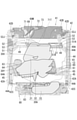
以下、本発明の一実施形態を図1~図32に基づいて説明する。本実施形態の遊技機10は、パチンコ遊技機であって、図1に示した前面のガラス窓10Wを通して図2に示した遊技板11の遊技領域R1を視認することができるようになっている。
[First Embodiment]
Hereinafter, an embodiment of the present invention will be described with reference to FIGS. 1 to 32. The gaming machine 10 of the present embodiment is a pachinko gaming machine, and the gaming area R1 of the gaming plate 11 shown in FIG. 2 can be visually recognized through the front glass window 10W shown in FIG. ..
遊技領域R1は、遊技板11の前面から突出したレール部材12によって囲まれ、レール部材12の左上部には進入口12Aが設けられている。そして、遊技機10の前面右下の操作ハンドル28(図1参照)を操作すると、その操作量に応じた強度で遊技球が進入口12Aから遊技領域R1内に打ち込まれて流下する。
The game area R1 is surrounded by a rail member 12 projecting from the front surface of the game plate 11, and an entrance 12A is provided at the upper left portion of the rail member 12. Then, when the operation handle 28 (see FIG. 1) at the lower right of the front surface of the game machine 10 is operated, the game ball is driven into the game area R1 from the entrance 12A with a strength corresponding to the operation amount and flows down.
遊技領域R1内には、略四角形の演出表示窓13が形成されている。そして、液晶モニタ14の液晶表示画面14Gが、演出表示窓13の奥部から前方に臨んでいて、その液晶表示画面14Gと遊技板11との間の空間内で可動役物30(図3参照)による可動演出が行われる。可動役物30の構成に関しては、後に詳説する。
A substantially quadrangular effect display window 13 is formed in the game area R1. Then, the liquid crystal display screen 14G of the liquid crystal monitor 14 faces forward from the back of the effect display window 13, and the movable accessory 30 (see FIG. 3) is in the space between the liquid crystal display screen 14G and the game board 11. ) Is used for the movable production. The configuration of the movable accessory 30 will be described in detail later.
演出表示窓13には、前方から装飾枠15が嵌め込まれていて、演出表示窓13の上辺部と両側辺部とから演出表示窓13内に遊技球が進入することを規制している。また、装飾枠15の上辺部とレール部材12との間には遊技球1球分の幅の上部通路R2が形成されている。そして、操作ハンドル28の操作量を調整することで、上部通路R2より右側に遊技球を流下させる右打ちと、上部通路R2より左側に遊技球を流下させる左打ちとに打ち分けることができる。
A decorative frame 15 is fitted into the effect display window 13 from the front, and the game ball is restricted from entering the effect display window 13 from the upper side portion and both side portions of the effect display window 13. Further, an upper passage R2 having a width equivalent to one game ball is formed between the upper side portion of the decorative frame 15 and the rail member 12. Then, by adjusting the operation amount of the operation handle 28, it is possible to strike a right-handed ball that causes the game ball to flow down to the right side of the upper passage R2 and a left-handed player that causes the game ball to flow down to the left side of the upper passage R2.
装飾枠15のうち演出表示窓13の下辺内面を覆った部分は、遊技球が転動可能なステージ21になっている。また、装飾枠15の一側辺下端部にはワープ孔21Aが設けられ、そこからステージ21上に遊技球が進入して後述する第1始動入賞口16Aの上方位置から排出されるようになっている。また、ステージ21の後縁部からは、ステージ後部壁21Bが起立している。なお、ステージ後部壁21Bの上縁部は前方に折れ曲がってステージ21を上方から覆う庇状になっている。
The portion of the decorative frame 15 that covers the inner surface of the lower side of the effect display window 13 is a stage 21 on which the game ball can roll. Further, a warp hole 21A is provided at the lower end of one side of the decorative frame 15, from which a game ball enters the stage 21 and is discharged from an upper position of the first starting winning opening 16A, which will be described later. ing. Further, the rear wall 21B of the stage stands up from the trailing edge of the stage 21. The upper edge of the rear wall 21B of the stage is bent forward to form an eave that covers the stage 21 from above.
遊技領域R1のうち演出表示窓13の下方領域における左右方向の略中央には第1始動入賞口16Aが設けられ、その第1始動入賞口16Aに対し、真下にはアウト口17、左側方には複数の普通入賞口18、右側方には大入賞口19が設けられている。また、遊技領域R1の右側領域のうち大入賞口19の上方には、第2始動入賞口16Bが設けられ、その第2始動入賞口16Bの上方には、始動ゲート22が設けられている。なお、大入賞口19と第2始動入賞口16Bとの間にも普通入賞口18が備えられている。
A first start winning opening 16A is provided in the substantially center of the game area R1 in the lower region of the effect display window 13 in the left-right direction. Is provided with a plurality of ordinary winning openings 18 and a large winning opening 19 on the right side. Further, in the right side region of the game area R1, a second start winning opening 16B is provided above the large winning opening 19, and a starting gate 22 is provided above the second starting winning opening 16B. A normal winning opening 18 is also provided between the large winning opening 19 and the second starting winning opening 16B.
また、第2始動入賞口16B及び大入賞口19は、開閉扉16T,19Tを有して、通常は閉塞されている。そして、始動ゲート22を遊技球が通過すると、それに起因して「普図判定」と呼ばれる当否判定が行われる。その判定結果は液晶表示画面14Gにて報知され、そこで当りになると第2始動入賞口16Bが開く。
Further, the second starting winning opening 16B and the large winning opening 19 have opening / closing doors 16T and 19T, and are normally closed. Then, when the game ball passes through the start gate 22, a hit / fail judgment called "normal drawing judgment" is performed due to the passing. The determination result is notified on the liquid crystal display screen 14G, and when it hits there, the second start winning opening 16B opens.
さらに、第1及び第2の始動入賞口16A,16Bに遊技球が入賞すると、それに起因して行われる「特図判定」と呼ばれる当否判定が行われる。その判定結果は、液晶表示画面14Gに3つの特別図柄14A,14B,14Cの変動表示後に停止表示したときの図柄組み合わせによって報知される。また、そこで当り(これを「大当り」という)になると、大入賞口19が所定期間に亘って開く大当り遊技が実行される。なお、何れの入賞口にも入賞しなかった遊技球は、アウト口17に取り込まれる。また、遊技領域R1全体には、複数の障害釘23が打ち込まれている。
Further, when a game ball wins a prize in the first and second starting winning openings 16A and 16B, a winning / failing determination called "special figure determination" is performed due to the winning. The determination result is notified on the liquid crystal display screen 14G by the symbol combination when the three special symbols 14A, 14B, and 14C are stopped and displayed after the variation display. Further, when a hit (this is referred to as a "big hit") occurs there, a big hit game in which the big winning opening 19 opens for a predetermined period is executed. The game ball that does not win in any of the winning openings is taken into the out opening 17. Further, a plurality of obstacle nails 23 are driven into the entire game area R1.
各入賞口に遊技球が入賞すると、その入賞数に応じた賞球が遊技機10の前面の上皿27(図1参照)に払い出される。その際の入賞球1球当りの賞球数は、大入賞口19が、他の入賞口より多くなっている。また、第1始動入賞口16Aには、遊技領域R1の左側領域を流下した遊技球は入賞し得るが、右側領域を流下した遊技球が第1始動入賞口16Aに入賞する確率は極めて低い。第2始動入賞口16Bは、その逆になっている。また、通常状態は、普図判定で当りになっても第2始動入賞口16Bの開閉扉16Tの開放時間は極めて短く、第2始動入賞口16Bへの入賞確率は極めて低い。さらに、大当りには「確変付き大当り」が設けられていて、確変付き大当りを引き当てて「確変状態」になると、特図判定で大当りになる確率が高くなりかつ、普図判定の当りによる第2始動入賞口16Bの開放時間が長くなる。そうすると、右打ちを行って第2始動入賞口16Bに遊技球を入賞させることが容易になると共に、右打ちを維持して大当り遊技を行えるので、通常状態に比べて格段に多くの賞球を獲得することが可能になる。
When a game ball wins in each winning opening, the prize balls corresponding to the number of winnings are paid out to the upper plate 27 (see FIG. 1) on the front surface of the game machine 10. At that time, the number of prize balls per winning ball is larger in the large winning opening 19 than in the other winning openings. Further, the game ball flowing down the left side region of the game area R1 can win a prize in the first starting winning opening 16A, but the probability that the game ball flowing down the right side region will win the first starting winning opening 16A is extremely low. The second starting winning opening 16B is the opposite. Further, in the normal state, the opening time of the opening / closing door 16T of the second starting winning opening 16B is extremely short even if it is a hit in the normal drawing determination, and the winning probability of the second starting winning opening 16B is extremely low. Furthermore, a "big hit with probability variation" is provided for the jackpot, and when the jackpot with probability variation is assigned to enter the "probability variation state", the probability of becoming a jackpot in the special figure judgment increases, and the second by the hit of the normal map judgment. The opening time of the starting winning opening 16B becomes longer. Then, it becomes easy to hit the right side to win the game ball in the second start winning opening 16B, and the big hit game can be performed while maintaining the right side hit, so that the number of prize balls is much larger than in the normal state. It will be possible to acquire.
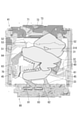
さて、本実施形態の遊技機10は、上記した通常状態や確変状態等の様々な状態の変化を演出するために、液晶表示画面14Gにキャラクター画像14Xやアイテム画像14Y等を表示する画像演出を行う。そして、この画像演出に加えて、図3に示すように、液晶表示画面14Gの前方で画像演出に登場するキャラクター等を模した可動演出部材30A,30Bを動作させる可動演出も可動役物30によって行う。
By the way, the gaming machine 10 of the present embodiment has an image effect of displaying a character image 14X, an item image 14Y, etc. on the liquid crystal display screen 14G in order to produce changes in various states such as the above-mentioned normal state and probable change state. conduct. Then, in addition to this image effect, as shown in FIG. 3, the movable effect 30 that operates the movable effect members 30A and 30B that imitate the characters appearing in the image effect in front of the liquid crystal display screen 14G is also performed by the movable accessory 30. conduct.
具体的には、図2に示すように、演出画像として、液晶表示画面14Gには、キャラクター画像14Xとしての「変身ヒーロー」が、アイテム画像14Yとしての「剣」を扱って敵(図示せず)と戦う画像が表示される。それに対し、可動役物30は、図9及び図4に示すように、キャラクター画像14Xを模したレリーフである「顔」の可動演出部材30Aと、アイテム画像14Yを模したレリーフである「剣」の可動演出部材30Bとを液晶表示画面14Gの前方に出現させる可動演出を行う。
Specifically, as shown in FIG. 2, as a production image, the "transformation hero" as the character image 14X handles the "sword" as the item image 14Y on the liquid crystal display screen 14G, and the enemy (not shown). ) Is displayed. On the other hand, as shown in FIGS. 9 and 4, the movable accessory 30 has a movable effect member 30A of the “face” which is a relief imitating the character image 14X, and a “sword” which is a relief imitating the item image 14Y. The movable effect member 30B and the movable effect member 30B of the above are performed to appear in front of the liquid crystal display screen 14G.
図6に示すように、「顔」の可動演出部材30Aは、「顔」の第1構成要素30Xとしての「目」を含んだ顔上部のレリーフである第1演出部材31と、第2構成要素30Yとしての「鼻」を含んだ顔中央部のレリーフである第2演出部材32と、下顎のレリーフである第3演出部材33とに分割されている。また、第1演出部材31は、第2演出部材32に対して可動状態に連結される一方、第3演出部材33は、第1及び第2の演出部材31,32から分離されている。そして、通常は、図5に示すように、第1と第2の演出部材31,32が前後に重ねられて演出表示窓13の上側後方位置で待機し、第3演出部材33が、演出表示窓13の下側後方位置で待機している。また、「剣」の可動演出部材30Bは、上下方向に延びた形状をなして、通常は、演出表示窓13の左側後方位置で待機している。そして、所定の遊技状態になると、図3に示すように、第1と第2の演出部材31,32が上下に展開した状態になって液晶表示画面14Gの前方に出現する共に、第3演出部材33が第2演出部材32の下方に隣接する位置に出現して、遊技者にキャラクターの「顔」を見せる可動演出が行われる。さらに、所定の条件が満たされると、図4に示すように、「剣」の可動演出部材30Bが右側にスライドして「顔」の可動演出部材30Aの一部を前方から覆い隠す可動演出が行われる。
As shown in FIG. 6, the movable effect member 30A of the "face" includes the first effect member 31 which is a relief of the upper part of the face including the "eyes" as the first component 30X of the "face" and the second configuration. It is divided into a second effect member 32 which is a relief of the central part of the face including a "nose" as an element 30Y, and a third effect member 33 which is a relief of the lower jaw. Further, the first effect member 31 is movably connected to the second effect member 32, while the third effect member 33 is separated from the first and second effect members 31 and 32. Then, normally, as shown in FIG. 5, the first and second effect members 31 and 32 are overlapped in the front-rear direction and stand by at the upper rear position of the effect display window 13, and the third effect member 33 displays the effect. It is waiting at the lower rear position of the window 13. Further, the movable effect member 30B of the "sword" has a shape extending in the vertical direction, and normally stands by at the left rear position of the effect display window 13. Then, when a predetermined gaming state is reached, as shown in FIG. 3, the first and second effect members 31 and 32 are expanded vertically and appear in front of the liquid crystal display screen 14G, and the third effect is achieved. The member 33 appears at a position adjacent to the lower part of the second effect member 32, and a movable effect is performed to show the player the "face" of the character. Further, when a predetermined condition is satisfied, as shown in FIG. 4, the movable effect member 30B of the "sword" slides to the right side to cover a part of the movable effect member 30A of the "face" from the front. Will be done.
第1及び第2の演出部材31,32は第1機構ユニット41によって駆動され、第3演出部材33は第2機構ユニット80によって駆動され、「剣」の可動演出部材30Bは、第3機構ユニット90によって駆動される。即ち、可動役物30は、第1~第3の駆動ユニット41,80,90に分割されている。また、これら第1~第3の駆動ユニット41,80,90は図11に示すようにモニタ支持枠24内に組み付けられている。
The first and second effect members 31 and 32 are driven by the first mechanism unit 41, the third effect member 33 is driven by the second mechanism unit 80, and the movable effect member 30B of the "sword" is the third mechanism unit. Driven by 90. That is, the movable accessory 30 is divided into first to third drive units 41, 80, 90. Further, these first to third drive units 41, 80, 90 are assembled in the monitor support frame 24 as shown in FIG.
図10に示すように、モニタ支持枠24は、前後より上下左右に大きく扁平な筐体構造をなし、前面全体が開口している。そして、モニタ支持枠24の前面が遊技板11の後面に重ねられた状態で固定されて、モニタ支持枠24内の空間は演出表示窓13より上下左右に広くなっている。また、モニタ支持枠24の後面には、演出表示窓13に対向するモニタ用開口24Aが形成され、そのモニタ用開口24Aが液晶モニタ14の液晶表示画面14Gによって後方から閉塞されている。
As shown in FIG. 10, the monitor support frame 24 has a flat housing structure that is larger in the vertical and horizontal directions than the front and rear, and the entire front surface is open. The front surface of the monitor support frame 24 is fixed so as to be overlapped with the rear surface of the game board 11, and the space inside the monitor support frame 24 is wider in the vertical and horizontal directions than the effect display window 13. Further, a monitor opening 24A facing the effect display window 13 is formed on the rear surface of the monitor support frame 24, and the monitor opening 24A is closed from behind by the liquid crystal display screen 14G of the liquid crystal monitor 14.
以下、第1機構ユニット41について詳説する。第1機構ユニット41は、図12(A)に抜き出して示した門形固定ベース42を有する。門形固定ベース42は、上下方向に延びた1対の側辺部42A(以下、「ベース側辺部42A」という)の上端部の間を上辺部42B(以下、「ベース上辺部42B」という)で連絡した構造をなし、モニタ支持枠24内の後部(奥部)に配置されて(図11参照)、両ベース側辺部42A,42Aがモニタ支持枠24の後面の両側縁部に螺子止めされると共に、ベース上辺部42Bがモニタ支持枠24の後面の上縁部に螺子止めされている。
Hereinafter, the first mechanism unit 41 will be described in detail. The first mechanism unit 41 has a gantry fixed base 42 extracted and shown in FIG. 12 (A). The gate-shaped fixed base 42 has an upper side portion 42B (hereinafter referred to as “base upper side portion 42B”) between the upper ends of a pair of side side portions 42A (hereinafter referred to as “base side side portion 42A”) extending in the vertical direction. ), Which is arranged in the rear part (rear part) in the monitor support frame 24 (see FIG. 11), and both base side sides 42A and 42A are screwed to both side edges of the rear surface of the monitor support frame 24. At the same time, the base upper side portion 42B is screwed to the upper edge portion of the rear surface of the monitor support frame 24.
図15に示すように、両ベース側辺部42A,42Aには、1対の従動スライダ45,45が上下動可能に支持されている。それら従動スライダ45,45は、別個に駆動源50,50を備える。そして、両駆動源50,50の動力を両従動スライダ45,45に伝達する迄の機構が、一部を除いて左右対称になっている。以下、第1機構ユニット41における左右対称な部分に関し、左右の一方(例えば、第1機構ユニット41を前方から見て右側部分)のみについて説明する。
As shown in FIG. 15, a pair of driven sliders 45, 45 are supported on both base side sides 42A, 42A so as to be vertically movable. The driven sliders 45, 45 separately include drive sources 50, 50. The mechanism for transmitting the power of both drive sources 50 and 50 to both driven sliders 45 and 45 is symmetrical except for a part. Hereinafter, only one of the left and right sides (for example, the right side portion when the first mechanism unit 41 is viewed from the front) will be described with respect to the symmetrical portion of the first mechanism unit 41.
図6に示すように、ベース側辺部42Aの下端部とベース上辺部42Bの上縁部とには、それぞれ前方に突出して上下方向で対向する下端支持壁42Cと上端支持壁42Dとが設けられ、それら上端支持壁42Dと下端支持壁42Cと間にレールシャフト43(例えば、断面円形の金属棒)が差し渡されている。そして、レールシャフト43とベース側辺部42A及びベース上辺部42Bの間に、上下に延びた中継スライダ44が配置され、その中継スライダ44の上下の両端部から前方に突出した1対の係合突部44A,44Aがレールシャフト43にスライド可能に係合している。また、図14に示すように、上述の従動スライダ45は、上下に延びたブロック形状をなして1対の係合突部44A,44Aの間に配置され、レールシャフト43が従動スライダ45を貫通してスライド可能に支持している。
As shown in FIG. 6, the lower end portion of the base side portion 42A and the upper edge portion of the base upper side portion 42B are provided with a lower end support wall 42C and an upper end support wall 42D that project forward and face each other in the vertical direction, respectively. A rail shaft 43 (for example, a metal rod having a circular cross section) is passed between the upper end support wall 42D and the lower end support wall 42C. Then, a relay slider 44 extending vertically is arranged between the rail shaft 43, the base side side portion 42A, and the base upper side portion 42B, and a pair of engagements protruding forward from the upper and lower ends of the relay slider 44. The protrusions 44A and 44A are slidably engaged with the rail shaft 43. Further, as shown in FIG. 14, the driven slider 45 described above is arranged between a pair of engaging protrusions 44A and 44A in a vertically extending block shape, and the rail shaft 43 penetrates the driven slider 45. And support it so that it can slide.
また、中継スライダ44の長手方向の途中部分には貫通孔44Hが形成され、その貫通孔44Hを横切る回転支持軸46Sに中継ギヤ46が回転可能に支持されている。そして、その中継ギヤ46の前側部分と噛合する可動ラック47が従動スライダ45に固定される一方、中継ギヤ46の後側部分と噛合する固定ラック48がベース側辺部42Aに固定されている。これにより、図14(A)~図14(C)に示すように、中継スライダ44が門形固定ベース42に対して上下の一方に移動すると、従動スライダ45が中継スライダ44に対して上下の一方に移動する。即ち、門形固定ベース42に対して従動スライダ45は中継スライダ44の倍の速度で移動する。換言すれば、門形固定ベース42に対する従動スライダ45の上下のストロークは、中継スライダ44の上下のストロークの倍になっている。
Further, a through hole 44H is formed in the middle portion of the relay slider 44 in the longitudinal direction, and the relay gear 46 is rotatably supported by a rotation support shaft 46S that crosses the through hole 44H. The movable rack 47 that meshes with the front side portion of the relay gear 46 is fixed to the driven slider 45, while the fixed rack 48 that meshes with the rear side portion of the relay gear 46 is fixed to the base side side portion 42A. As a result, as shown in FIGS. 14A to 14C, when the relay slider 44 moves up and down with respect to the gantry fixed base 42, the driven slider 45 moves up and down with respect to the relay slider 44. Move to one side. That is, the driven slider 45 moves at twice the speed of the relay slider 44 with respect to the gantry fixed base 42. In other words, the vertical stroke of the driven slider 45 with respect to the gantry fixed base 42 is twice the vertical stroke of the relay slider 44.
図12(A)に示すように、中継スライダ44の上端部からは、傾斜部49Aが門形固定ベース42の横方向の中央側に向かって斜め上方に張り出し、その傾斜部49Aの上端部からさらに中央に向かって水平部49が水平に延びている。また、水平部49には、中継スライダ44の直動方向と直交する方向(即ち、水平方向)に延びた係合長孔51が形成されている。そして、中継スライダ44が可動範囲の上端に配置されると、図12(A)に示すように水平部49がベース上辺部42Bの上縁部前方に位置し、中継スライダ44が可動範囲の下端に配置されると、図13(B)に示すように水平部49がベース上辺部42Bより下方に位置する。なお、以下、係合長孔51のうちベース上辺部42Bの横方向の中央側の端部を「内側端部51B」、その反対側の端部を「外側端部51A」ということとする。
As shown in FIG. 12A, the inclined portion 49A projects diagonally upward from the upper end portion of the relay slider 44 toward the horizontal center side of the portal fixing base 42, and from the upper end portion of the inclined portion 49A. Further, the horizontal portion 49 extends horizontally toward the center. Further, the horizontal portion 49 is formed with an engaging elongated hole 51 extending in a direction orthogonal to the linear motion direction (that is, the horizontal direction) of the relay slider 44. When the relay slider 44 is arranged at the upper end of the movable range, the horizontal portion 49 is located in front of the upper edge portion of the base upper side portion 42B as shown in FIG. 12 (A), and the relay slider 44 is located at the lower end of the movable range. When arranged in, the horizontal portion 49 is located below the base upper side portion 42B as shown in FIG. 13 (B). Hereinafter, of the engaging elongated holes 51, the end portion on the lateral center side of the base upper side portion 42B is referred to as “inner end portion 51B”, and the end portion on the opposite side thereof is referred to as “outer end portion 51A”.
水平部49に駆動源50の動力を伝達するための駆動レバー52が、ベース上辺部42Bに回動可能に支持されている。駆動レバー52は、ベース上辺部42Bの前面に配置され、駆動レバー52の回転支持軸52Jは、ベース上辺部42Bの下端一側部寄り位置に回転可能に支持されている。詳細には、図13(B)に示すように、回転支持軸52Jの中心は、中継スライダ44の上下動に伴った係合長孔51の移動軌跡S1のうち外側端部51A側の境界線K1寄り位置に配置されている。また、駆動レバー52の先端部からは係合突部53が前方に突出していて、その係合突部53が係合長孔51に抜け止めされかつスライド可能に係合している。
A drive lever 52 for transmitting the power of the drive source 50 to the horizontal portion 49 is rotatably supported by the base upper side portion 42B. The drive lever 52 is arranged on the front surface of the base upper side portion 42B, and the rotation support shaft 52J of the drive lever 52 is rotatably supported at a position closer to the lower end side portion of the base upper side portion 42B. Specifically, as shown in FIG. 13B, the center of the rotation support shaft 52J is a boundary line on the outer end 51A side of the movement locus S1 of the engagement slot 51 accompanying the vertical movement of the relay slider 44. It is located closer to K1. Further, the engaging protrusion 53 protrudes forward from the tip of the drive lever 52, and the engaging protrusion 53 is prevented from coming off from the engaging elongated hole 51 and is slidably engaged.
図15に示すように、駆動レバー52の回転支持軸52Jには、ギヤ52Gが一体回転可能に固定されて、ベース上辺部42Bの後面に配置されている。そして、ベース上辺部42Bの後面のうちギヤ52Gの近傍に駆動源50が取り付けられている。駆動源50は、例えば、ステッピングモータの一端に減速機を組み付けてなり、減速機の出力回転軸には図示しない出力ギヤが固定されている。そして、その駆動源50の出力ギヤが駆動レバー52のギヤ52Gに結合され、これにより駆動レバー52が駆動源50によって回転駆動される。
As shown in FIG. 15, a gear 52G is integrally rotatably fixed to the rotation support shaft 52J of the drive lever 52 and is arranged on the rear surface of the base upper side portion 42B. A drive source 50 is attached in the vicinity of the gear 52G on the rear surface of the base upper side portion 42B. The drive source 50 is, for example, assembled with a speed reducer at one end of a stepping motor, and an output gear (not shown) is fixed to the output rotation shaft of the speed reducer. Then, the output gear of the drive source 50 is coupled to the gear 52G of the drive lever 52, whereby the drive lever 52 is rotationally driven by the drive source 50.
ここで、図15の右側の駆動レバー52のギヤ52Gに対しては、駆動源50の出力ギヤが直接噛合し(図16(A)参照)、図15の左側の駆動レバー52のギヤ52Gに対しては、駆動源50の出力ギヤがアイドルギヤ54を介して間接的に噛合している(図16(B)参照)。このように、駆動源50の出力ギヤを駆動レバー52のギヤ52Gに噛合させる際に、アイドルギヤ54を介在させるか否かにより、駆動源50の出力ギヤからギヤ52Gに伝達される回転方向が逆向きになる。本実施形態では、これにより、両駆動源50,50を同じ回転方向に回転させて、1対の駆動レバー52,52に左右対称な逆向きの回転動作を行わせることができる。即ち、1対の可動部品(駆動レバー52,52)を左右対称に駆動する両駆動源50,50の制御が容易になるという効果を奏する。
Here, the output gear of the drive source 50 directly meshes with the gear 52G of the drive lever 52 on the right side of FIG. 15 (see FIG. 16A), and engages with the gear 52G of the drive lever 52 on the left side of FIG. On the other hand, the output gear of the drive source 50 is indirectly meshed via the idle gear 54 (see FIG. 16B). In this way, when the output gear of the drive source 50 is meshed with the gear 52G of the drive lever 52, the rotation direction transmitted from the output gear of the drive source 50 to the gear 52G depends on whether or not the idle gear 54 is interposed. It goes in the opposite direction. In the present embodiment, this makes it possible to rotate both drive sources 50 and 50 in the same rotation direction so that the pair of drive levers 52 and 52 perform symmetrical rotation operations in opposite directions. That is, it has the effect of facilitating control of both drive sources 50 and 50 that drive a pair of movable parts (drive levers 52 and 52) symmetrically.
なお、左右の駆動源50,50と駆動レバー52のギヤ52Gとの間に、それぞれアイドルギヤを介在させて、一方のアイドルギヤの数と他方とアイドルギヤの数が偶数と奇数とで異なる構成でも同様の効果を奏する。また、左右の駆動源50,50をQ42Bに取り付ける前後の向きを逆向きにしても同様の効果を奏する。
An idle gear is interposed between the left and right drive sources 50 and 50 and the gear 52G of the drive lever 52, and the number of idle gears on one side and the number of idle gears on the other side are different between even and odd numbers. But it has the same effect. Further, the same effect can be obtained even if the left and right drive sources 50 and 50 are attached to the Q42B in the opposite directions.
図16に示すように、駆動レバー52のギヤ52Gには、駆動レバー52の後面に回転可能に支持された位置検出用ギヤ55も噛合している。また、位置検出用ギヤ55から側方に扇形突片55Aが突出している。これに対し、ベース上辺部42Bの後面には、扇形突片55Aの回動領域の一端部に光学センサ55Sが備えられている。そして、図12(B)に示すように、駆動レバー52が直立姿勢より係合長孔51の内側端部51B側に傾いた途中基準位置を境にして、その途中基準位置から係合突部53が外側端部51A側に移動する駆動レバー52の回動範囲で、光学センサ55Sが扇形突片55Aによって光を遮られてオン状態になり、それ以外の駆動レバー52の回動範囲で光学センサ55Sがオフ状態になる。
As shown in FIG. 16, the gear 52G of the drive lever 52 also meshes with the position detection gear 55 rotatably supported on the rear surface of the drive lever 52. Further, the fan-shaped projecting piece 55A projects laterally from the position detection gear 55. On the other hand, on the rear surface of the base upper side portion 42B, an optical sensor 55S is provided at one end of the rotation region of the fan-shaped projecting piece 55A. Then, as shown in FIG. 12B, the engagement protrusion portion is defined from the intermediate reference position where the drive lever 52 is tilted toward the inner end portion 51B side of the engagement slot 51 from the upright posture. In the rotation range of the drive lever 52 in which 53 moves toward the outer end portion 51A, the optical sensor 55S is turned on by being blocked by the fan-shaped projecting piece 55A, and is optical in the rotation range of the drive lever 52 other than that. The sensor 55S is turned off.
図15に示すように、従動スライダ45,45の間には、架橋部材60が差し渡されている。具体的には、架橋部材60の横方向の端部には、図17に示すように、横長の複数の長孔60Aが上下方向に間隔を空けて設けられている。これら長孔60Aに対し、従動スライダ45の前面に長孔60Aに対応した図示しない螺子孔が形成されている。そして、長孔60A群を従動スライダ45の螺子孔に対向させた状態で長孔60A群の前側に縦長の帯板60Bが宛がわれ、その帯板60Bの貫通孔と架橋部材60の長孔60Aとに通されたビス60Cが従動スライダ45の螺子孔に螺合されている。これにより、架橋部材60の両端部が従動スライダ45に対して横方向への直動と回動を許容された状態で、従動スライダ45と一体に上下方向に移動するようになっている。
As shown in FIG. 15, a cross-linking member 60 is passed between the driven sliders 45 and 45. Specifically, as shown in FIG. 17, a plurality of horizontally long holes 60A are provided at the lateral ends of the cross-linking member 60 at intervals in the vertical direction. With respect to these elongated holes 60A, a screw hole (not shown) corresponding to the elongated hole 60A is formed on the front surface of the driven slider 45. Then, with the elongated hole 60A group facing the screw hole of the driven slider 45, a vertically long strip 60B is addressed to the front side of the elongated strip 60A group, and the through hole of the strip 60B and the elongated hole of the bridging member 60 are addressed. The screw 60C passed through the 60A is screwed into the screw hole of the driven slider 45. As a result, both ends of the cross-linking member 60 are allowed to move in the vertical direction integrally with the driven slider 45 in a state where the driven slider 45 is allowed to move linearly and rotate in the lateral direction.
図15に示すように、架橋部材60を後方から見て右側の端部からは、レバー支持突壁63が上方に突出している。そして、そのレバー支持突壁63の前面上端部に回動レバー64の基端部が回転可能に連結されている。また、図6に示すように、回動レバー64の先端部は、第2演出部材32の後面側における横方向の一端部(詳細には、第2演出部材32のうち第2構成要素30Yである「鼻」の下側部分)に重ねられてヒンジ軸体64Aにてヒンジ連結されている。
As shown in FIG. 15, the lever support protrusion 63 projects upward from the end on the right side when the cross-linking member 60 is viewed from the rear. The base end portion of the rotary lever 64 is rotatably connected to the upper end portion of the front surface of the lever support protrusion 63. Further, as shown in FIG. 6, the tip end portion of the rotary lever 64 is a lateral end portion on the rear surface side of the second effect member 32 (specifically, the second component 30Y of the second effect member 32). It is overlapped with a certain "lower part of the nose") and hinged with a hinge shaft body 64A.
さらに、図15に示すように、架橋部材60の下端部のうちレバー支持突壁63の延長位置には、駆動源70が取り付けられている。駆動源70は、駆動源50と同様に、ステッピングモータの一端に減速機を組み付けてなる。また、回動レバー64の基端部に固定された図示しないギヤがレバー支持突壁63の内部に収容され、そのギヤと駆動源70の出力ギヤとが複数のアイドルギヤを介して連結されている。これにより回動レバー64が駆動源70によって回転駆動され、第2演出部材32の横方向の一端部が円弧を描いて動く。また、回動レバー64は、その回動範囲の一端である「原点」では、図6に示すように回動中心から垂下された原点姿勢となり、回動範囲の他端である「終端点」では、図8に示すように回動レバー64が回動中心の斜め上方に延びた終端点姿勢になる。
Further, as shown in FIG. 15, a drive source 70 is attached to an extension position of the lever support protrusion 63 in the lower end portion of the cross-linking member 60. Like the drive source 50, the drive source 70 is formed by assembling a speed reducer to one end of the stepping motor. Further, a gear (not shown) fixed to the base end portion of the rotary lever 64 is housed inside the lever support protrusion 63, and the gear and the output gear of the drive source 70 are connected via a plurality of idle gears. There is. As a result, the rotary lever 64 is rotationally driven by the drive source 70, and one end of the second effect member 32 in the lateral direction moves in an arc. Further, at the "origin" which is one end of the rotation range of the rotation lever 64, the origin posture is hung from the rotation center as shown in FIG. 6, and the "end point" which is the other end of the rotation range. Then, as shown in FIG. 8, the rotation lever 64 is in the end point posture extending diagonally upward of the rotation center.
図15に示すように、架橋部材60のうち横方向におけるレバー支持突壁63の反対側の端部には第1カム孔61が形成され、そこに第2演出部材32の後面から後方に突出した第1係合突部65が抜け止めされかつスライド可能に係合している。具体的には、第1カム孔61は、レバー支持突壁63側に向かうに従って下るように傾斜して直線状に延びかつ、下側の端部寄り位置で屈曲し、そこから下側の端部までが、水平に延びた水平エンド部61Aになっている。そして、回動レバー64が可動範囲の原点で、第2演出部材32が「原点姿勢」になると、第1係合突部65が第1カム孔61の水平エンド部61Aに位置し、そこから回動レバー64が可動範囲の終端点に向かって移動していくと、回動レバー64の回動中心とヒンジ軸体64Aの中心と第1係合突部65の中心とが一直線上に並ぶ位置(以下、「中心直列位置」という)までは、第1係合突部65が第1カム孔61内を水平エンド部61Aから離れる側に移動する(図21参照)。そして、回動レバー64が中心直列位置を通過して上方に回動すると、第1係合突部65が第1カム孔61内を水平エンド部61Aに接近する側に移動し、回動レバー64が終端点に達して第2演出部材32が「終端点姿勢」になると第1係合突部65が第1カム孔61のうち水平エンド部61A内に位置して止まる(図22参照)。
As shown in FIG. 15, a first cam hole 61 is formed at the end of the cross-linking member 60 on the opposite side of the lever support protrusion 63 in the lateral direction, and the first cam hole 61 projects rearward from the rear surface of the second effect member 32. The first engaging protrusion 65 is prevented from coming off and is slidably engaged. Specifically, the first cam hole 61 is inclined downward toward the lever support protrusion 63 side, extends linearly, bends at a position closer to the lower end, and bends from there to the lower end. Up to the portion is a horizontal end portion 61A extending horizontally. Then, when the rotation lever 64 is the origin of the movable range and the second effect member 32 is in the "origin posture", the first engaging protrusion 65 is located at the horizontal end portion 61A of the first cam hole 61, and from there. As the rotary lever 64 moves toward the end point of the movable range, the center of rotation of the rotary lever 64, the center of the hinge shaft body 64A, and the center of the first engaging protrusion 65 are aligned in a straight line. Until the position (hereinafter referred to as "center series position"), the first engaging protrusion 65 moves in the first cam hole 61 to the side away from the horizontal end portion 61A (see FIG. 21). Then, when the rotary lever 64 passes through the central series position and rotates upward, the first engaging protrusion 65 moves in the first cam hole 61 to the side approaching the horizontal end portion 61A, and the rotary lever 64 moves upward. When 64 reaches the end point and the second effect member 32 is in the "end point posture", the first engaging protrusion 65 is positioned in the horizontal end portion 61A of the first cam hole 61 and stops (see FIG. 22). ..
架橋部材60のうち第1カム孔61に対してレバー支持突壁63側の隣には第2カム孔62が形成されている。そして、第2演出部材32から後方に突出した第2係合突部66が第2カム孔62に抜け止めされかつスライド可能に係合している。第2カム孔62は、レバー支持突壁63側に向かうに従って下るように傾斜して延びた傾斜辺部62Bと、傾斜辺部62Bの上端部からレバー支持突壁63側へと略水平に延びた横辺部62Aとを有するV字形状をなしている。また、傾斜辺部62Bは、僅かに下方に膨らむように湾曲すると共に、下端部に第1カム孔61の下端部と同様の水平エンド部62Cを有する。さらには、横辺部62Aも、僅かに下方に湾曲している。
A second cam hole 62 is formed next to the lever support protrusion 63 side with respect to the first cam hole 61 of the cross-linking member 60. Then, the second engaging protrusion 66 protruding rearward from the second effect member 32 is prevented from coming off the second cam hole 62 and is slidably engaged. The second cam hole 62 extends substantially horizontally from the inclined side portion 62B extending downward toward the lever support protrusion 63 side and the upper end portion of the inclined side portion 62B toward the lever support protrusion 63 side. It has a V-shape with a horizontal side portion 62A. Further, the inclined side portion 62B is curved so as to bulge slightly downward, and has a horizontal end portion 62C at the lower end portion similar to the lower end portion of the first cam hole 61. Further, the lateral side portion 62A is also slightly curved downward.
そして、回動レバー64が中心直列位置より上側に位置しているときには(図22参照)、第2係合突部66が第2カム孔62における横辺部62A内に位置し、回動レバー64が中心直列位置より下側に位置しているときには、第2係合突部66が第2カム孔62における傾斜辺部62B内に位置する。また、回動レバー64が回動範囲の原点で第2演出部材32が原点姿勢になると、第2係合突部66が第2カム孔62の水平エンド部62C内に位置する。
When the rotary lever 64 is located above the central series position (see FIG. 22), the second engaging protrusion 66 is located in the lateral side portion 62A of the second cam hole 62, and the rotary lever 64 is located. When 64 is located below the central series position, the second engaging protrusion 66 is located within the inclined side portion 62B in the second cam hole 62. Further, when the rotation lever 64 is at the origin of the rotation range and the second effect member 32 is in the origin posture, the second engaging protrusion 66 is located in the horizontal end portion 62C of the second cam hole 62.
図19及び図20に示すように、第2演出部材32は、回動レバー64と反対側の側縁部から後方に突出する土手部32Uを有し、その土手部32Uに支持板79が片持ち梁状に支持されて回動レバー64側へと延びている。即ち、第2演出部材32は、前面を装飾された本体部32Hの後側に支持板79を対向状態に備えている。また、前記した回動レバー64の先端部は、本体部32Hにて連結され、前記した第1及び第2の係合突部65,66は、支持板79に備えられている。そして、第1演出部材31が、本体部32Hと支持板79との間に受容されるようになっている。
As shown in FIGS. 19 and 20, the second effect member 32 has a bank portion 32U projecting rearward from the side edge portion on the opposite side of the rotary lever 64, and the support plate 79 is one piece on the bank portion 32U. It is supported like a beam and extends toward the rotary lever 64. That is, the second effect member 32 is provided with a support plate 79 facing each other on the rear side of the main body portion 32H whose front surface is decorated. Further, the tip portion of the rotary lever 64 is connected by the main body portion 32H, and the first and second engaging protrusions 65 and 66 described above are provided on the support plate 79. Then, the first effect member 31 is received between the main body portion 32H and the support plate 79.
図15に示すように第1演出部材31には、後面下縁部における回動レバー64側の一端位置とその斜め上方位置とに、第1と第2のリンク67,68の上端部がそれぞれ回転可能に連結されている。一方の第1リンク67は、回動レバー64から離れる側の斜め下方に延びて支持板79における横方向の途中位置に回動可能に連結されている。また、他方の第2リンク68も、同様に斜め下方に延びて土手部32Uの上端部に回動可能に連結されている。そして、これら第1及び第2のリンク67,68によって平行リンクが構成されて、第1演出部材31が第2演出部材32に対して一定姿勢を維持して上下動する。
As shown in FIG. 15, the first effect member 31 has upper end portions of the first and second links 67 and 68 at one end position on the rotary lever 64 side and an obliquely upper position thereof at the lower edge portion of the rear surface, respectively. It is rotatably connected. On the other hand, the first link 67 extends diagonally downward on the side away from the rotary lever 64 and is rotatably connected to a lateral intermediate position on the support plate 79. Further, the other second link 68 also extends diagonally downward and is rotatably connected to the upper end portion of the bank portion 32U. Then, a parallel link is formed by the first and second links 67 and 68, and the first effect member 31 moves up and down while maintaining a constant posture with respect to the second effect member 32.
第1リンク67の長手方向の上端寄り位置からは後方に向かって係合突部67Tが突出していて、それが支持板79の先端部に備えた長孔67Mに抜け止めされかつスライド可能に係合している。また、第2リンク68の長手方向の上端寄り位置からは前方に係合突部68Tが突出していて、第1演出部材31の先端部に備えた長孔68Mに抜け止めされかつスライド可能で係合している。また、これら係合突部67T,68Tが長孔67M,68Mの端部に当接することで第2演出部材32に対する第1演出部材31の可動範囲が限定されている。そして、第1演出部材31が可動範囲の一端(即ち、下端)に配置されると(図18参照)、図5に示すように、第1演出部材31の略全体が第2演出部材32の後方に隠れ、可動範囲の他端(即ち,上端)に配置されると(図15参照)、図6に示すように、第1演出部材31のうち下縁部のみが第2演出部材32の後方に隠れ、第1演出部材31全体が第2演出部材32の上方に位置した状態になる。また、図15に示すように、土手部32Uの上端部と第2リンク68との連結部には、第1演出部材31を第2演出部材32に対する可動範囲の上端位置に向けて付勢する弾性部材68S(例えば、トーションコイルバネ)が取り付けられている。
The engaging protrusion 67T protrudes rearward from the position near the upper end in the longitudinal direction of the first link 67, and it is prevented from coming off by the elongated hole 67M provided at the tip of the support plate 79 and is slidably engaged. It fits. Further, the engaging protrusion 68T protrudes forward from the position near the upper end in the longitudinal direction of the second link 68, and is prevented from coming off by the elongated hole 68M provided at the tip of the first effect member 31 and is slidable and engaged. It fits. Further, the movable range of the first effect member 31 with respect to the second effect member 32 is limited by the contact of these engaging protrusions 67T and 68T with the ends of the elongated holes 67M and 68M. Then, when the first effect member 31 is arranged at one end (that is, the lower end) of the movable range (see FIG. 18), as shown in FIG. 5, substantially the entire first effect member 31 is the second effect member 32. When it is hidden behind and placed at the other end (that is, the upper end) of the movable range (see FIG. 15), as shown in FIG. 6, only the lower edge portion of the first effect member 31 is the second effect member 32. It hides behind and the entire first effect member 31 is located above the second effect member 32. Further, as shown in FIG. 15, the first effect member 31 is urged toward the upper end position of the movable range with respect to the second effect member 32 at the connecting portion between the upper end portion of the bank portion 32U and the second link 68. An elastic member 68S (for example, a torsion coil spring) is attached.
第1演出部材31の後面には、上縁部に沿って横方向に延びる支持レール69が備えられ、そこに直線状に延びた長孔69Mが形成されている。そして、第2演出部材32が原点姿勢になると長孔69Mが水平に延びた状態になる。
The rear surface of the first effect member 31 is provided with a support rail 69 extending laterally along the upper edge portion, and a long hole 69M extending linearly is formed therein. Then, when the second effect member 32 is in the origin posture, the elongated hole 69M is in a horizontally extended state.
図6に示すように、ベース上辺部42Bの横方向における一端寄り位置には、補助アーム71が回動可能に支持され、その補助アーム71の先端部に備えた係合突部71Tが、第1演出部材31の長孔69Mに抜け止めされかつスライド可能に係合している。また、ベース上辺部42Bと補助アーム71との間には、第1演出部材31を上方に引き上げる方向に付勢する弾性部材72が取り付けられている。
As shown in FIG. 6, an auxiliary arm 71 is rotatably supported at a position closer to one end in the lateral direction of the base upper side portion 42B, and an engaging protrusion 71T provided at the tip end portion of the auxiliary arm 71 is a second. 1 The elongated hole 69M of the effect member 31 is prevented from coming off and is slidably engaged. Further, an elastic member 72 that urges the first effect member 31 in a direction of pulling it upward is attached between the base upper side portion 42B and the auxiliary arm 71.
具体的には、補助アーム71は、クラック状に屈曲していて、先端側が基端側より下方に位置している。そして、補助アーム71は、先端側が水平に延びた姿勢となる第1位置と、そこから下方に30~45度程度回動した第2位置との間で回動するようにメカストッパにて回動範囲が限定されている。また、引張コイルバネである弾性部材72の一端部は、補助アーム71の屈曲部の下部に取り付けられる一方、弾性部材72の他端部は、ベース上辺部42Bの上縁部のうち補助アーム71の回動中心から離れた位置に取り付けられている。また、弾性部材72の途中部分は、ベース上辺部42Bの上縁部に回転可能に支持されたローラ73に上方から押し付けられて屈曲している。そして、補助アーム71が第1姿勢から第2姿勢に向かうに従って弾性部材72の弾性変形量が増し、補助アーム71を第1姿勢側に付勢することで、第1演出部材31が上方に付勢される。
Specifically, the auxiliary arm 71 is bent like a crack, and the tip end side is located below the proximal end side. Then, the auxiliary arm 71 is rotated by a mechanical stopper so as to rotate between the first position in which the tip side is in a horizontally extended posture and the second position rotated downward by about 30 to 45 degrees. The range is limited. Further, one end of the elastic member 72, which is a tension coil spring, is attached to the lower part of the bent portion of the auxiliary arm 71, while the other end of the elastic member 72 is the upper edge portion of the base upper side portion 42B of the auxiliary arm 71. It is attached at a position away from the center of rotation. Further, the intermediate portion of the elastic member 72 is bent from above by being pressed from above by the roller 73 rotatably supported by the upper edge portion of the base upper side portion 42B. Then, as the auxiliary arm 71 moves from the first posture to the second posture, the amount of elastic deformation of the elastic member 72 increases, and by urging the auxiliary arm 71 toward the first posture side, the first effect member 31 is attached upward. Be energized.
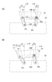
第1機構ユニット41の構成に関する説明は、以上である。次に、第2機構ユニット80の構成について説明する。図11に示すように、第2機構ユニット80は、第1機構ユニット41の下方においてモニタ支持枠24の後面下縁部に重ねて固定される板状ベース83を有する。図23に示すように、板状ベース83の上縁部の2箇所には、第1と第2のアーム81,82が回動可能に支持されている。また、第1と第2の両アーム81,82は、第1と第2のアーム81,82の回動軸間の距離より短くなっていて、第1と第2の両アーム81,82の互いの基端部に干渉することなく回転することができる(図26(A)~図26(C)参照)。
The description of the configuration of the first mechanism unit 41 has been described above. Next, the configuration of the second mechanism unit 80 will be described. As shown in FIG. 11, the second mechanism unit 80 has a plate-shaped base 83 that is overlapped and fixed to the lower edge portion of the rear surface of the monitor support frame 24 below the first mechanism unit 41. As shown in FIG. 23, the first and second arms 81 and 82 are rotatably supported at two locations on the upper edge of the plate-shaped base 83. Further, both the first and second arms 81 and 82 are shorter than the distance between the rotation axes of the first and second arms 81 and 82, and the distance between the first and second arms 81 and 82 is shorter than that of the first and second arms 81 and 82. It can rotate without interfering with each other's base ends (see FIGS. 26 (A) to 26 (C)).
また、図23に示すように、第2機構ユニット80を後方から見て右側の第1アーム81の先端部は、第3演出部材33の後面下縁部における右側端部にヒンジ軸体81Aにて回動可能に連結されている。また、第3演出部材33の後面下縁部には、横方向の略中央位置から左側端部に亘って直線状に延びた長孔33Mが形成されている。そして、後方から見て左側の第2アーム82の先端部に備えた係合突部82Aが長孔33Mに抜け止めされかつスライド可能に係合している。なお、詳細には、第3演出部材33は、ベースプレートを前側から装飾カバーで覆った構成となっていて、長孔33Mは、ベースプレートに形成されている(図23では、装飾カバーは図示されていない。)。また、第1アーム81の回動中心とヒンジ軸体81Aの中心とを結ぶ回動基準線81Lの長さと、第2アーム82の回動中心と係合突部82Aの中心とを結ぶ回動基準線82Lの長さが同じになっている。
Further, as shown in FIG. 23, the tip end portion of the first arm 81 on the right side when the second mechanism unit 80 is viewed from the rear is attached to the hinge shaft body 81A at the right end portion in the rear surface lower edge portion of the third effect member 33. Is rotatably connected. Further, in the lower edge portion of the rear surface of the third effect member 33, a long hole 33M extending linearly from a substantially central position in the lateral direction to the left end portion is formed. The engaging protrusion 82A provided at the tip of the second arm 82 on the left side when viewed from the rear is prevented from coming off by the elongated hole 33M and is slidably engaged. In detail, the third effect member 33 has a structure in which the base plate is covered with a decorative cover from the front side, and the elongated hole 33M is formed in the base plate (in FIG. 23, the decorative cover is shown). do not have.). Further, the length of the rotation reference line 81L connecting the rotation center of the first arm 81 and the center of the hinge shaft body 81A, and the rotation connecting the rotation center of the second arm 82 and the center of the engaging protrusion 82A. The length of the reference line 82L is the same.
板状ベース83の後面には、スライド板84が重ねて配置されている。スライド板84は横方向に延びた帯板の一端部を上下に幅広にした形状をなしている。また、スライド板84の長手方向の2箇所には、横長の2つの長孔84A,84Aが横一列に並べて設けられ、板状ベース83から後方に突出した1対の係合突部83T,83Tがそれら長孔84A,84Aに抜け止めされかつスライド可能に係合している。そして、各長孔84Aの両端部と係合突部83Tとの当接によってスライド板84の直動範囲が規定されている。
A slide plate 84 is arranged on the rear surface of the plate-shaped base 83 so as to be overlapped with each other. The slide plate 84 has a shape in which one end of a strip extending in the lateral direction is widened vertically. Further, two horizontally long holes 84A and 84A are provided side by side in a horizontal row at two locations in the longitudinal direction of the slide plate 84, and a pair of engaging protrusions 83T and 83T protruding rearward from the plate-shaped base 83. Are held in place and slidably engaged with the elongated holes 84A and 84A. The linear motion range of the slide plate 84 is defined by the contact between both ends of each elongated hole 84A and the engaging protrusion 83T.
スライド板84の上面には、長手方向の2箇所にラック84B,84Cが形成されている。これに対し、第1と第2のアーム81,82の基端部には第1と第2のピニオン81G,82Gが一体回転可能に固定され、それら第1と第2のピニオン81G,82Gが第1と第2のラック84B,84Cにそれぞれ噛合している。また、第1と第2のピニオン81G,82Gのピッチ円の径は同じになっている。これにより、第1と第2のアーム81,82が連動して同一速度で同一方向に回転する。また、第1アーム81の回動基準線81Lと、第2アーム82の回動基準線82Lとは非平行になっていて、スライド板84が直動範囲の一端に位置すると、図23及び図27(B)に示すように、両第1と第2のアーム81,82の両回動基準線81L,82Lが、それぞれの回動中心から上方に延びかつ、上下方向に対して互いに離れる側に所定角度だけ傾いた第1出現状態になる。また、スライド板84が直動範囲の他端に位置すると、図24及び図26(A)に示すように、第1と第2のアーム81,82が垂下し、第3演出部材33全体が板状ベース83の前方に重なり、かつ、その第3演出部材33と板状ベース83との間に第1と第2のアーム81,82の全体が収まった収納状態になる。
Racks 84B and 84C are formed at two locations in the longitudinal direction on the upper surface of the slide plate 84. On the other hand, the first and second pinions 81G and 82G are integrally rotatably fixed to the base ends of the first and second arms 81 and 82, and the first and second pinions 81G and 82G are integrally rotatably fixed. It meshes with the first and second racks 84B and 84C, respectively. Further, the diameters of the pitch circles of the first and second pinions 81G and 82G are the same. As a result, the first and second arms 81 and 82 are interlocked and rotate in the same direction at the same speed. Further, when the rotation reference line 81L of the first arm 81 and the rotation reference line 82L of the second arm 82 are not parallel to each other and the slide plate 84 is located at one end of the linear motion range, FIGS. 23 and 23 and FIGS. As shown in 27 (B), the rotation reference lines 81L and 82L of both the first and second arms 81 and 82 extend upward from their respective rotation centers and are separated from each other in the vertical direction. It becomes the first appearance state tilted by a predetermined angle. Further, when the slide plate 84 is located at the other end of the linear motion range, the first and second arms 81 and 82 hang down as shown in FIGS. 24 and 26 (A), and the entire third effect member 33 is formed. It is in a stored state in which the first and second arms 81 and 82 are entirely accommodated in front of the plate-shaped base 83 and between the third effect member 33 and the plate-shaped base 83.
スライド板84の幅広側の端部には、縦長の係合長孔85が形成されている。また、スライド板84の幅広側の端部と板状ベース83との間には、スライド板84の幅よりも直径が僅かに大きい中継ギヤ86が備えられ、板状ベース83に回動可能に支持されている。更には、中継ギヤ86の外縁寄り位置からは、係合突部86Aが後方に突出していて、係合長孔85に抜け止めされかつスライド可能に係合している。そして、中継ギヤ86が180度以上回転して、係合突部86Aの中心の回動軌跡である円の直径分だけスライド板84が直動する。その中継ギヤ86を回転駆動するための駆動源87が、板状ベース83の前面の一端部に取り付けられている。駆動源87は、ステッピングモータの一端に減速機を組み付けてなり、減速機の出力回転軸には出力ギヤが固定されている。また、駆動源87は、板状ベース83に形成された陥没部に出力ギヤが受容された状態にして板状ベース83に固定され、その陥没部の側部に形成された貫通孔を通して出力ギヤが板状ベース83の後面の中継ギヤ86に噛合している。これにより、スライド板84が駆動源87から動力を受けてスライドする。
A vertically long engaging elongated hole 85 is formed at the end of the slide plate 84 on the wide side. Further, a relay gear 86 having a diameter slightly larger than the width of the slide plate 84 is provided between the wide end of the slide plate 84 and the plate-shaped base 83 so that the slide plate 84 can be rotated. It is supported. Further, the engaging protrusion 86A protrudes rearward from the position near the outer edge of the relay gear 86, and is prevented from coming off from the engaging elongated hole 85 and is slidably engaged. Then, the relay gear 86 rotates 180 degrees or more, and the slide plate 84 moves linearly by the diameter of the circle which is the rotation locus of the center of the engaging protrusion 86A. A drive source 87 for rotationally driving the relay gear 86 is attached to one end of the front surface of the plate-shaped base 83. The drive source 87 has a speed reducer assembled at one end of the stepping motor, and an output gear is fixed to the output rotation shaft of the speed reducer. Further, the drive source 87 is fixed to the plate-shaped base 83 in a state where the output gear is received by the recessed portion formed in the plate-shaped base 83, and the output gear is passed through a through hole formed in the side portion of the recessed portion. Is meshed with the relay gear 86 on the rear surface of the plate-shaped base 83. As a result, the slide plate 84 slides by receiving power from the drive source 87.
なお、中継ギヤ86は、係合突部86Aがスライド板84の係合長孔85の内周面の下端に係止されるまで回転可能となっている。係合突部86Aは、第1と第2アーム81,82が第1出現位置に配置されているときには、係合長孔85の下端には到達しておらず(図23参照)、中継ギヤ86は、回転範囲の途中位置に配置されている。従って、第1と第2アーム81,82が収納状態となっているときに、駆動源87により中継ギヤ86が回転すると、スライド板84は、直動範囲の一端から他端へ移動してから、再び一端側へと若干戻った第2出現位置(図25及び図27(B)参照)にまで移動するようになっている。即ち、第3演出部材33は、図26(A)に示す収納位置から、図26(B)、図26(C)に示すように前方から見て右回りに回動して、図27(D)に示す第1出現位置へと到達した後、若干左回りに回動して図27(E)に示す第2出現位置に配置される。
The relay gear 86 can rotate until the engaging protrusion 86A is locked to the lower end of the inner peripheral surface of the engaging elongated hole 85 of the slide plate 84. The engagement protrusion 86A does not reach the lower end of the engagement slot 85 when the first and second arms 81 and 82 are arranged at the first appearance positions (see FIG. 23), and the relay gear. The 86 is arranged at a position in the middle of the rotation range. Therefore, when the relay gear 86 is rotated by the drive source 87 while the first and second arms 81 and 82 are in the retracted state, the slide plate 84 moves from one end to the other end of the linear motion range. , It is designed to move to the second appearance position (see FIGS. 25 and 27 (B)) which is slightly returned to one end side again. That is, the third effect member 33 rotates clockwise when viewed from the front as shown in FIGS. 26 (B) and 26 (C) from the storage position shown in FIG. 26 (A). After reaching the first appearance position shown in D), it rotates slightly counterclockwise and is arranged at the second appearance position shown in FIG. 27 (E).
板状ベース83の後面には、駆動源87と反対側の端部に引張コイルバネである弾性部材88の一端部が取り付けられ、その弾性部材88の他端部がスライド板84の長手方向の中間部に取り付けられている。そして、第3演出部材33が収納状態になったときに弾性部材88の変形量が最も大きくなり、第3演出部材33の上方への移動を弾性部材88の弾発力によって補助するようになっている。
On the rear surface of the plate-shaped base 83, one end of an elastic member 88, which is a tension coil spring, is attached to the end opposite to the drive source 87, and the other end of the elastic member 88 is in the middle of the slide plate 84 in the longitudinal direction. It is attached to the part. Then, when the third effect member 33 is in the retracted state, the amount of deformation of the elastic member 88 becomes the largest, and the upward movement of the third effect member 33 is assisted by the elastic force of the elastic member 88. ing.
第2機構ユニット80の構成に関する説明は、以上である。次に、第3機構ユニット90の構成について説明する。図9に示すように、第3機構ユニット90には、前方から見て第1機構ユニット41の左側部の前側に配置されている。また、第3機構ユニット90は、上端部にベース部91を有し、そのベース部91から「剣」の可動演出部材30Bが垂下された状態で横方向に直動する構成になっている。具体的には、ベース部91は、横長の略長方形のベース部本体91Hの右側部の上端から水平に延長部91Eが延びた形状をなしている。そして、ベース部91の上面と左側面とからそれぞれ突出した複数の固定用突部91Aがモニタ支持枠24の左側縁部の上部と上縁部とに螺子止めされている。
The description of the configuration of the second mechanism unit 80 has been described above. Next, the configuration of the third mechanism unit 90 will be described. As shown in FIG. 9, the third mechanism unit 90 is arranged on the front side of the left side portion of the first mechanism unit 41 when viewed from the front. Further, the third mechanism unit 90 has a base portion 91 at the upper end portion thereof, and has a configuration in which the movable effect member 30B of the “sword” is hung from the base portion 91 and directly moves in the lateral direction. Specifically, the base portion 91 has a shape in which the extension portion 91E extends horizontally from the upper end of the right side portion of the horizontally long substantially rectangular base portion main body 91H. A plurality of fixing protrusions 91A protruding from the upper surface and the left side surface of the base portion 91 are screwed to the upper portion and the upper edge portion of the left side edge portion of the monitor support frame 24.
図28に示すように、ベース部91の後面には、延長部91Eの先端部と、その反対側のベース部本体91Hの一側部の上部とに1対の台座部92,92が形成されている。また、台座部92,92にそれぞれ形成された1対の角溝92M,92Mに、金属製の丸棒であるガイドシャフト93の両端部が受容されている。そして、台座部92,92の後面に押え板92P,92Pが螺子止めされて、ガイドシャフト93が角溝92Mに抜け止めされると共に、各角溝92Mの一端に備えた壁部によってガイドシャフト93の横方向への移動が規制されている。また、ガイドシャフト93には、1対の摺動リング93R,93Rが挿通されている。それら摺動リング93Rは、摺動性が高い樹脂(例えば、ポリアセタール)で構成されかつ円筒状になっている。
As shown in FIG. 28, on the rear surface of the base portion 91, a pair of pedestal portions 92, 92 are formed on the tip portion of the extension portion 91E and the upper portion of one side portion of the base portion main body 91H on the opposite side thereof. ing. Further, both ends of the guide shaft 93, which is a metal round bar, are received by the pair of square grooves 92M and 92M formed in the pedestals 92 and 92, respectively. Then, the pressing plates 92P and 92P are screwed to the rear surfaces of the pedestals 92 and 92, the guide shaft 93 is prevented from coming off by the square groove 92M, and the guide shaft 93 is provided by the wall portion provided at one end of each square groove 92M. The lateral movement of the is restricted. Further, a pair of sliding rings 93R and 93R are inserted through the guide shaft 93. The sliding ring 93R is made of a highly slidable resin (for example, polyacetal) and has a cylindrical shape.
ガイドシャフト93とベース部91との間には、水平方向に延びたスライド部材94が備えられている。スライド部材94の両端部には、1対のリング受容溝94M,94Mが形成されている。各リング受容溝94Mは、中央部の溝幅が両端部の溝幅に比べて広くなっている。そして、各リング受容溝94Mの中央部に摺動リング93Rが受容されてスライド部材94に対する横方向への移動が規制されている。
A slide member 94 extending in the horizontally direction is provided between the guide shaft 93 and the base portion 91. A pair of ring receiving grooves 94M and 94M are formed at both ends of the slide member 94. In each ring receiving groove 94M, the groove width at the central portion is wider than the groove width at both ends. The sliding ring 93R is received in the central portion of each ring receiving groove 94M, and lateral movement with respect to the slide member 94 is restricted.
スライド部材94のうち延長部91E側の一端部には、後面から押え板94Pが重ねられて螺子止めされている。これにより、一方の摺動リング93Rがリング受容溝94Mに抜け止めされている。
A pressing plate 94P is overlapped with a holding plate 94P from the rear surface and screwed to one end of the slide member 94 on the extension portion 91E side. As a result, one of the sliding rings 93R is prevented from coming off by the ring receiving groove 94M.
スライド部材94の他端部から略中央部に亘る範囲には、「剣」の可動演出部材30Bから上方に延長された延長プレート95の上縁部が重ねて螺子止めされている。これにより、他方の摺動リング93Rがリング受容溝94Mに抜け止めされると共に、スライド部材94と共に「剣」の可動演出部材30Bが直動する。
In the range extending from the other end of the slide member 94 to the substantially central portion, the upper edge portion of the extension plate 95 extending upward from the movable effect member 30B of the "sword" is overlapped and screwed. As a result, the other sliding ring 93R is prevented from coming off by the ring receiving groove 94M, and the movable effect member 30B of the "sword" moves linearly together with the slide member 94.
ベース部本体91Hの後面の下縁部には、横長のスライド中継部材96が備えられている。スライド中継部材96には、1対の横長の長孔96A,96Aが横一列に並べて設けられ、それら長孔96A,96Aにベース部本体91Hから突出した係合突部96T,96Tが抜け止めされかつスライド可能に係合している。また、スライド中継部材96の上面には、ラック96Rが形成されている。
A horizontally long slide relay member 96 is provided on the lower edge portion of the rear surface of the base portion main body 91H. The slide relay member 96 is provided with a pair of horizontally long holes 96A and 96A arranged side by side in a horizontal row, and the engaging protrusions 96T and 96T protruding from the base portion main body 91H are prevented from coming off from the long holes 96A and 96A. And it is slidably engaged. Further, a rack 96R is formed on the upper surface of the slide relay member 96.
ベース部本体91Hの後面のうち延長部91Eの反対側の端部には、駆動源97が取り付けられている。駆動源97は、ステッピングモータの一端に減速機を組み付けてなり、減速機の出力回転軸に固定された出力ギヤが、ラック96Rに噛合している。
A drive source 97 is attached to the end of the rear surface of the base portion main body 91H on the opposite side of the extension portion 91E. The drive source 97 has a speed reducer assembled at one end of the stepping motor, and an output gear fixed to the output rotation shaft of the speed reducer meshes with the rack 96R.
ベース部本体91Hの後面のうち横方向の略中央における下端寄り位置には、中継レバー98の基端部が回動可能に取り付けられている。また、中継レバー98の基端部の外側面には、ギヤ98Gが形成されていて、そのギヤ98Gがラック96Rに噛合している。そして、中継レバー98の先端部にそなえた係合突部98Aが、延長プレート95に形成された縦長の係合長孔95Mに抜け止めされかつスライド可能に係合している。これにより、駆動源97の動力がスライド中継部材96,中継レバー98を介して延長プレート95に伝達されて、「剣」の可動演出部材30Bが横方向に直動する。また、「剣」の可動演出部材30Bの下端部には、上下方向に延びた回転軸を中心に回転する1対のローラ95R,95Rが備えられ、それらローラ95R,95Rを移動可能に収容する溝形ガイド95Gが、モニタ支持枠24の左側の下端寄り位置に配されている。第3機構ユニット90の構成に関する説明は以上である。
The base end portion of the relay lever 98 is rotatably attached to the rear surface of the base portion main body 91H at a position near the lower end in the substantially center in the lateral direction. Further, a gear 98G is formed on the outer surface of the base end portion of the relay lever 98, and the gear 98G meshes with the rack 96R. The engaging protrusion 98A provided at the tip of the relay lever 98 is prevented from coming off and is slidably engaged with the vertically long engaging elongated hole 95M formed in the extension plate 95. As a result, the power of the drive source 97 is transmitted to the extension plate 95 via the slide relay member 96 and the relay lever 98, and the movable effect member 30B of the "sword" moves linearly in the lateral direction. Further, a pair of rollers 95R and 95R that rotate around a rotation axis extending in the vertical direction are provided at the lower end of the movable effect member 30B of the "sword", and these rollers 95R and 95R are movably accommodated. The groove-shaped guide 95G is arranged at a position near the lower end on the left side of the monitor support frame 24. This concludes the description of the configuration of the third mechanism unit 90.
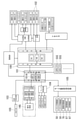
図30には、遊技機10の制御系のブロック図が示されている。同図に示すように、遊技機10は、メイン制御基板100とサブ制御基板101とを有する。メイン制御基板100は、乱数を生成していて、遊技球が入賞口に入賞してそれが賞球センサ102にて検出されると、検出タイミングで乱数が取得される。そして、その乱数に基づいて前述した普図判定や特図判定等を行って、通常状態か、確変状態か、後述するリーチ状態か等の遊技状態を決定するステータスデータを生成し、サブ制御基板101に付与する。
FIG. 30 shows a block diagram of the control system of the gaming machine 10. As shown in the figure, the gaming machine 10 has a main control board 100 and a sub control board 101. The main control board 100 generates a random number, and when a game ball wins a prize in the winning opening and is detected by the prize ball sensor 102, the random number is acquired at the detection timing. Then, based on the random number, the above-mentioned normal figure judgment, special figure judgment, etc. are performed to generate status data for determining the game state such as the normal state, the probabilistic state, or the reach state described later, and the sub control board. It is given to 101.
サブ制御基板101は、そのステータスデータに基づいて、遊技演出の全般を制御する。具体的には、サブ制御基板101は、遊技機10のスピーカ10Sから出力する音声を音声制御回路103を介して制御したり、遊技機10の前面や遊技板11に分散配置されているLEDやランプをランプ制御回路104を介して制御する。それらに加え、サブ制御基板101は、可動役物30に備えられた各センサの検出信号に基づいて可動役物30の状態を監視しながら、モータ駆動制御回路105にモータ駆動指令を出力して可動役物30を制御する。
The sub control board 101 controls the overall game effect based on the status data. Specifically, the sub-control board 101 controls the sound output from the speaker 10S of the gaming machine 10 via the voice control circuit 103, or has LEDs distributed on the front surface of the gaming machine 10 or the gaming board 11. The lamp is controlled via the lamp control circuit 104. In addition to these, the sub-control board 101 outputs a motor drive command to the motor drive control circuit 105 while monitoring the state of the movable accessory 30 based on the detection signals of the sensors provided in the movable accessory 30. The movable accessory 30 is controlled.
図30~図32には、サブ制御基板101のCPU101Aが可動役物30を制御する際に実行する可動演出処理プログラムPG1が示されている。この可動演出処理プログラムPG1に関しては、次述する遊技機10の動作と併せて説明する。
30 to 32 show a movable effect processing program PG1 executed when the CPU 101A of the sub control board 101 controls the movable accessory 30. The movable effect processing program PG1 will be described together with the operation of the gaming machine 10 described below.
本実施形態の遊技機10の構成に関する説明は以上である。次に、この遊技機10の動作について説明する。可動役物30は、通常は、駆動源50,50,70,87,97が停止した休止状態になっている。その休止状態にするためには、全ての駆動源50,50,70,87,97を原点に移動してから非通電状態にする。そして、休止状態になると、図2に示すように、液晶表示画面14Gによる画像演出の妨げにならないように「顔」の可動演出部材30Aのうち第1と第2の演出部材31,32は演出表示窓13より上側で待機し、第3演出部材33は演出表示窓13より下方で待機し、さらには、「剣」の可動演出部材30Bは演出表示窓13の左方に待機する。
This concludes the description of the configuration of the gaming machine 10 of the present embodiment. Next, the operation of the gaming machine 10 will be described. The movable accessory 30 is usually in a dormant state in which the drive sources 50, 50, 70, 87, 97 are stopped. In order to put it into the hibernation state, all the drive sources 50, 50, 70, 87, 97 are moved to the origin and then turned off. Then, in the hibernation state, as shown in FIG. 2, the first and second effect members 31 and 32 of the movable effect member 30A of the "face" are produced so as not to interfere with the image effect by the liquid crystal display screen 14G. The third effect member 33 waits below the effect display window 13, and the movable effect member 30B of the "sword" stands by to the left of the effect display window 13.
また、上記した「原点」は、駆動源50,50,70,87,97の全てにおいて可動範囲の一端の設定されている。また、駆動源70にて駆動される回動レバー64において前述したが、駆動源50,50,70,87,97にとっての原点は、それら駆動源50,50,70,87,97の出力ギヤと連動して動く可動部にとっての「原点」でもある。さらに、駆動源50,50,70,87,97の全てにおいて可動範囲のうち原点と反対側の他端は「終端点」ということとし、それは前述の可動部にとっての「終端点」でもある。
Further, the above-mentioned "origin" is set at one end of the movable range in all of the drive sources 50, 50, 70, 87, 97. Further, as described above for the rotary lever 64 driven by the drive source 70, the origin for the drive sources 50, 50, 70, 87, 97 is the output gears of the drive sources 50, 50, 70, 87, 97. It is also the "origin" for the moving parts that move in conjunction with. Further, in all of the drive sources 50, 50, 70, 87, 97, the other end of the movable range on the opposite side to the origin is referred to as a "termination point", which is also a "termination point" for the above-mentioned movable portion.
また、以下、駆動源同士を区別して説明する場合には、それらの区別を容易にするために、駆動源50,50を「スライダ用駆動源50,50」といい、駆動源70を「顔傾動用駆動源70」といい、駆動源87を「顎用駆動源87」といい、駆動源97を「剣用駆動源97」ということとして詳説する。
Further, when the drive sources are described separately below, the drive sources 50 and 50 are referred to as “slider drive sources 50 and 50” and the drive source 70 is referred to as a “face” in order to facilitate the distinction between them. It will be described in detail as "tilted drive source 70", the drive source 87 is referred to as "jaw drive source 87", and the drive source 97 is referred to as "sword drive source 97".
両スライダ用駆動源50,50が原点に配置されると、図12(A)に示すように、駆動レバー52,52は垂直起立状態から外側に回動して係合突部53,53が係合長孔51,51の外側端部51A,51Aに当接した状態になる。このとき、係合長孔51,51を有する中継スライダ44,44は、第1と第2の演出部材31,32等の自重により下向きの負荷を受け、その負荷は、原点姿勢の駆動レバー52を外側に回動させて係合突部53を外側端部51Aに押し付けるように作用する。つまり、両スライダ用駆動源50,50が原点に配置されると、負荷によって係合長孔51,51と駆動レバー52,52とによるメカロックを深める、所謂、「セルフロック状態」になる。これにより、両スライダ用駆動源50,50は非通電状態されても原点に維持される。
When the drive sources 50 and 50 for both sliders are arranged at the origin, as shown in FIG. 12 (A), the drive levers 52 and 52 rotate outward from the vertically standing state, and the engaging protrusions 53 and 53 are engaged. It is in a state of being in contact with the outer end portions 51A, 51A of the engaging elongated holes 51, 51. At this time, the relay sliders 44, 44 having the engaging elongated holes 51, 51 receive a downward load due to their own weights of the first and second effect members 31, 32, etc., and the load is the drive lever 52 in the origin posture. Acts so as to press the engaging protrusion 53 against the outer end 51A by rotating the engaging protrusion 53 outward. That is, when the drive sources 50 and 50 for both sliders are arranged at the origin, a so-called "self-locking state" is obtained in which the mechanical lock by the engaging elongated holes 51 and 51 and the drive levers 52 and 52 is deepened by the load. As a result, the drive sources 50 and 50 for both sliders are maintained at the origin even when the power is not supplied.
顔傾動用駆動源70が原点に配置されると、図6に示すように、上述の通り回動レバー64は回動中心から垂下した状態になる。この状態で中継スライダ44,44が原点に配置されると、第1演出部材31がモニタ支持枠24の上部内面に当接するか補助アーム71にて上方への移動を規制され、図5に示すように、第1と第2の演出部材31,32が重なり、第2演出部材32の上方への移動も規制される。即ち、顔傾動用駆動源70は、両スライダ用駆動源50,50と共に原点に配置された状態で、非通電状態されても原点に維持される。
When the face tilting drive source 70 is arranged at the origin, as shown in FIG. 6, the rotation lever 64 is in a state of hanging from the rotation center as described above. When the relay sliders 44 and 44 are arranged at the origin in this state, the first effect member 31 comes into contact with the upper inner surface of the monitor support frame 24 or is restricted from moving upward by the auxiliary arm 71, as shown in FIG. As described above, the first and second effect members 31 and 32 overlap each other, and the upward movement of the second effect member 32 is also restricted. That is, the face tilting drive source 70 is arranged at the origin together with the drive sources 50 and 50 for both sliders, and is maintained at the origin even when the power is not supplied.
顎用駆動源87が原点に配置されると、図24に示すように、中継ギヤ86の係合突部86Aが、中継ギヤ86の回動中心に対して同図の左側でかつ僅かに下方に位置した状態になる。この状態から長孔84Aをさらに下方に移動させるように力が作用しても、第1アーム81とスライド板84との間の図示しないメカストッパによって、スライド板84は同図の右側には動かない。即ち、弾性部材88の付勢力によって第1アーム81とスライド板84との間の図示しないメカストッパ同士の押し付け力が増加するセルフロック状態になり、顎用駆動源87は、原点に配置された状態で非通電状態されても原点に維持される。
When the jaw drive source 87 is arranged at the origin, as shown in FIG. 24, the engaging protrusion 86A of the relay gear 86 is on the left side of the figure and slightly downward with respect to the rotation center of the relay gear 86. It will be in the state of being located in. Even if a force acts to move the elongated hole 84A further downward from this state, the slide plate 84 does not move to the right side in the figure due to the mechanical stopper (not shown) between the first arm 81 and the slide plate 84. .. That is, a self-locking state is set in which the pressing force between the mechanical stoppers (not shown) between the first arm 81 and the slide plate 84 increases due to the urging force of the elastic member 88, and the jaw drive source 87 is arranged at the origin. It is maintained at the origin even if it is de-energized.
剣用駆動源97が原点に配置されると、図29の中継レバー98が回動中心から同図の右側に延びた水平姿勢よりさら下方に傾斜した傾斜姿勢になり、中継レバー98とベース部91との間に備えたメカストッパによって位置決めされる。これにより、「剣」の可動演出部材30Bを、同図の左側、つまり、演出表示窓13の中央側に移動させる力が仮に作用してセルフロック状態になる。よって、剣用駆動源97は、非通電状態されても原点に維持される。
When the drive source 97 for the sword is arranged at the origin, the relay lever 98 in FIG. 29 is in an inclined posture that is inclined further downward from the horizontal posture extending from the center of rotation to the right side in the figure, and the relay lever 98 and the base portion. It is positioned by a mechanical stopper provided between the 91 and 91. As a result, a force for moving the movable effect member 30B of the "sword" to the left side of the figure, that is, to the center side of the effect display window 13, temporarily acts to enter the self-locking state. Therefore, the drive source 97 for the sword is maintained at the origin even when it is de-energized.
可動役物30の休止状態に関する説明は以上である。遊技機10は、通常は、確変状態ではない通常状態になっている。そこで、遊技者は、遊技機10による遊技を開始する場合には、操作ハンドル28(図1参照)にて左打ちを行う。そして、左側の遊技領域R1を流下する複数の遊技球の一部が第1始動入賞口16Aに入賞すると、特図判定が行われて、図2に示した3つの特別図柄14A,14B,14Cがスロットのように変動表示され、例えば、左、右、中央の順番で特別図柄14A,14B,14Cが停止表示される。その際、例えば、先に停止表示された左右の特別図柄14A,14Cが同じ図柄となるリーチ状態では、そうでない場合に比べて中央の特別図柄14Bが長く変動表示してから停止表示される。そして、特別図柄14A,14B,14Cの全て同じ図柄(即ち、ゾロ目)になると大当りとなり、そうでなければ外れとなる。
This concludes the description of the dormant state of the movable accessory 30. The gaming machine 10 is usually in a normal state, which is not a probable change state. Therefore, when the player starts the game by the gaming machine 10, the player strikes left with the operation handle 28 (see FIG. 1). Then, when a part of the plurality of game balls flowing down the game area R1 on the left side wins the first start winning opening 16A, a special symbol determination is performed, and the three special symbols 14A, 14B, 14C shown in FIG. 2 are performed. Is displayed in a variable manner like a slot, and for example, the special symbols 14A, 14B, and 14C are stopped and displayed in the order of left, right, and center. At that time, for example, in the reach state in which the left and right special symbols 14A and 14C that are previously stopped and displayed have the same symbol, the central special symbol 14B is variably displayed for a longer time than in the case where it is not, and then the stop display is performed. Then, if the special symbols 14A, 14B, and 14C all have the same symbol (that is, doublet), it becomes a big hit, and if not, it becomes a miss.
ここで、リーチ状態では、液晶表示画面14Gに、特別図柄14A,14B,14Cと共に、キャラクター画像14Xである「変身ヒーロー」が、アイテム画像14Yである「剣」を持った状態で表示され、図示しないキャラクター画像である「敵」と戦う画像演出が行われる。そして、リーチ状態から外れになると(即ち、「リーチ外れ」になると)、戦いの勝敗がつかずに画像演出が終了するか、変身ヒーローが敵に負けて画像演出が終了する。一方、リーチ状態から当りになると(即ち、「リーチ当り」になると)、変身ヒーローが敵に勝利した状態で画像演出が終了し、その後、可動役物30が始動して可動演出が行われてから前述の大当り遊技に突入する。
Here, in the reach state, the character image 14X "transformation hero" is displayed on the liquid crystal display screen 14G together with the special symbols 14A, 14B, 14C while holding the item image 14Y "sword". An image production that fights against the "enemy", which is a character image that does not exist, is performed. Then, when it goes out of reach (that is, when it goes out of reach), the image production ends without winning or losing the battle, or the transformation hero loses to the enemy and the image production ends. On the other hand, when it becomes a hit from the reach state (that is, when it becomes a "reach hit"), the image production ends with the transformation hero winning the enemy, and then the movable character 30 starts and the movable production is performed. It rushes into the above-mentioned big hit game.
このとき、リーチ当りが、「確変付き大当り」でない場合には、第1の可動演出が行われ、「確変付き大当り」である場合には、第2の可動演出が行われる。第1と第2の可動演出は中盤までは同じであり、終盤のみが異なり、サブ制御基板101のCPU101Aが、図30~図32の可動演出処理プログラムPG1を実行することで第1又は第2の可動演出が制御される。
At this time, if the reach hit is not "big hit with probability variation", the first movable effect is performed, and if it is "big hit with probability variation", the second movable effect is performed. The first and second movable effects are the same until the middle stage, only the final stage is different, and the CPU 101A of the sub control board 101 executes the movable effect processing program PG1 of FIGS. 30 to 32 to execute the first or second movable effect. Movable production is controlled.
具体的には、CPU101Aにて可動演出処理プログラムPG1が実行されると、最初に非通電状態であった全ての駆動源50,50,70,87,97が通電状態とされ(S11)、それぞれ原点に維持されるように制御される(S12)。
Specifically, when the movable effect processing program PG1 is executed by the CPU 101A, all the drive sources 50, 50, 70, 87, 97 that were initially in the non-energized state are energized (S11), respectively. It is controlled to be maintained at the origin (S12).
次いで、両スライダ用駆動源50,50が終端点寄りの反転基準位置に向かって移動するように制御されて(S13)、駆動レバー52,52が鉛直垂下姿勢になるまで回転されてから、両スライダ用駆動源50,50の回転方向が反転して駆動レバー52,52が前述の途中基準位置(図12B)より僅かに原点側にずれたダミー位置へと移動するように両スライダ用駆動源50,50が制御される(S14)。
Next, the drive sources 50 and 50 for both sliders are controlled to move toward the inversion reference position near the end point (S13), and the drive levers 52 and 52 are rotated until they are in the vertical hanging posture. The drive sources for both sliders are driven so that the rotation directions of the slider drive sources 50 and 50 are reversed and the drive levers 52 and 52 move to a dummy position slightly shifted to the origin side from the above-mentioned midway reference position (FIG. 12B). 50 and 50 are controlled (S14).
これら制御により、架橋部材60は可動範囲の下端位置に向かって移動し、それに伴って、第1と第2の演出部材31,32が互いに上下にずれながら降下し、途中で第1と第2の演出部材31,32が完全に展開した状態になってさらに降下する。そして、図6に示すように、架橋部材60が可動範囲の下端位置に至ったときに、「顔」の可動演出部材30Aのうち顎以外の全体が液晶表示画面14Gの前方に位置して、一瞬、「鼻先下がりの横顔」になるが、即座に架橋部材60が上昇して「鼻先下がりの横顔」が消えていく。
By these controls, the cross-linking member 60 moves toward the lower end position of the movable range, and accordingly, the first and second effect members 31 and 32 descend while shifting from each other up and down, and the first and second members are in the middle. The effect members 31 and 32 of the above are fully expanded and further descend. Then, as shown in FIG. 6, when the cross-linking member 60 reaches the lower end position of the movable range, the entire movable effect member 30A of the “face” other than the chin is located in front of the liquid crystal display screen 14G. For a moment, it becomes a "profile with the tip of the nose down", but immediately the cross-linking member 60 rises and the "profile with the tip of the nose down" disappears.
また、駆動レバー52,52がダミー位置に移動するように両スライダ用駆動源50,50が制御されている間(S14)、両スライダ用駆動源50,50の両光学センサ55S,55Sの検出信号が、オフ状態からオン状態に切り替わったか否かがチェックされる(S15のYESのループ)。そして、何れか一方のスライダ用駆動源50の光学センサ55Sがオン状態に切り替わったら(S15のNO)、そのタイミングにおける一方のスライダ用駆動源50の位置が維持されるように、一方のスライダ用駆動源50が通電状態で停止される(S16)。そして、他方のスライダ用駆動源50の光学センサ55Sがオン状態に切り替わったか否かをチェックする(S17のNOのループ)。そして、他方のスライダ用駆動源50の光学センサ55Sがオン状態に切り替わったら(S17のYES)、そのタイミングにおける他方のスライダ用駆動源50の位置が維持されるように、他方のスライダ用駆動源50が通電状態で停止される(S18)。これらにより、左右のスライダ用駆動源50,50の間の遅れが解消されて、図12(B)に示すように、両スライダ用駆動源50,50及び両駆動レバー52,52は、共にダミー位置より僅かに手前の途中基準位置に配置される。
Further, while the drive sources 50 and 50 for both sliders are controlled so that the drive levers 52 and 52 move to the dummy position (S14), the detection of both optical sensors 55S and 55S of the drive sources 50 and 50 for both sliders. It is checked whether or not the signal has switched from the off state to the on state (YES loop in S15). Then, when the optical sensor 55S of one of the slider drive sources 50 is switched to the ON state (NO in S15), the position of the one slider drive source 50 at that timing is maintained for one slider. The drive source 50 is stopped in the energized state (S16). Then, it is checked whether or not the optical sensor 55S of the other slider drive source 50 is switched to the ON state (NO loop of S17). Then, when the optical sensor 55S of the other slider drive source 50 is switched to the ON state (YES in S17), the position of the other slider drive source 50 is maintained at that timing, so that the other slider drive source is maintained. 50 is stopped in the energized state (S18). As a result, the delay between the left and right slider drive sources 50 and 50 is eliminated, and as shown in FIG. 12B, both the slider drive sources 50 and 50 and both the slider drive levers 52 and 52 are dummy. It is placed at the reference position on the way slightly before the position.
この状態になってから、例えば、100[msec]後に両スライダ用駆動源50,50が終端点へと移動して架橋部材60が降下するように制御される(S19)。その降下動作中に、顔傾動用駆動源70が原点から回動レバー64が水平姿勢になる水平基準位置に移動するように制御されると共に、顎用駆動源87は、第3演出部材33がステージ21より上方で水平姿勢になる第1出現位置に移動するように制御される(S19)。これにより、図7に示すように、変身ヒーローの「口を閉じた横顔」が液晶表示画面14Gの前方に出現する。
After this state is reached, for example, after 100 [msec], the drive sources 50 and 50 for both sliders are controlled to move to the end point and the cross-linking member 60 is lowered (S19). During the descent operation, the face tilting drive source 70 is controlled to move from the origin to the horizontal reference position where the rotation lever 64 is in the horizontal posture, and the jaw drive source 87 is the third effect member 33. It is controlled to move to the first appearance position where the posture becomes horizontal above the stage 21 (S19). As a result, as shown in FIG. 7, the transformation hero's "profile with closed mouth" appears in front of the liquid crystal display screen 14G.
このとき、架橋部材60には、弾性部材72の弾発力が上向きの力として作用するが、その弾発力が重力負荷より大きく作用しても、図8に示すように、係合長孔51及び駆動レバー52が上向の力に対してセルフロック状態になっているのでスライダ用駆動源50,50への負荷は小さい。また、両スライダ用駆動源50,50は通電状態になって終端点に維持されているので、確実にセルフロック状態が維持される。
At this time, the elastic force of the elastic member 72 acts on the cross-linking member 60 as an upward force, but even if the elastic force acts larger than the gravitational load, as shown in FIG. 8, the engaging elongated hole Since the 51 and the drive lever 52 are in a self-locking state with respect to the upward force, the load on the slider drive sources 50 and 50 is small. Further, since the drive sources 50 and 50 for both sliders are energized and maintained at the end points, the self-locking state is surely maintained.
上記した変身ヒーローの「口を閉じた横顔」の出現後、顔傾動用駆動源70と顎用駆動源87とが終端点に移動するように制御される(S20)。これにより、図8及び図9に示すように、回動レバー64が上向きの傾斜姿勢になって、第2演出部材32と第3演出部材33とが同図の右側端部を支点して上下に分かれるように傾動し、変身ヒーローの「口を閉じた横顔」が「口を開けた横顔」に変化する。
After the appearance of the above-mentioned transformation hero's "profile with closed mouth", the face tilting drive source 70 and the chin drive source 87 are controlled to move to the end point (S20). As a result, as shown in FIGS. 8 and 9, the rotary lever 64 is in an upward tilted posture, and the second effect member 32 and the third effect member 33 move up and down with the right end portion of the figure as a fulcrum. The transformation hero's "profile with closed mouth" changes to "profile with open mouth".
変身ヒーローの「口を開けた横顔」が所定時間維持されたら(S21でYES)、顔傾動用駆動源70及び顎用駆動源87が原点に移動するように制御される(S22)。これにより、図6に示すように、可動演出部材30Aは、「鼻先下がりの横顔」になる。
When the transformation hero's "profile with open mouth" is maintained for a predetermined time (YES in S21), the face tilting drive source 70 and the chin drive source 87 are controlled to move to the origin (S22). As a result, as shown in FIG. 6, the movable effect member 30A becomes a "profile with the tip of the nose down".
この状態で特図判定の「大当り」が「確変付き大当り」であったか否かが判別され(S23)、「確変付き大当り」でなかった場合は(S23でNO)、両スライダ用駆動源50,50が原点に移動するように制御される(S27)。これにより、全ての駆動源50,50,70,87,97が原点に配置された状態になる。そして、それら全ての駆動源50,50,70,87,97への通電が停止されて休止状態になり(S28)、可動演出処理プログラムPG1が終了する。
In this state, it is determined whether or not the "big hit" of the special figure determination is "big hit with probability variation" (S23), and if it is not "big hit with probability variation" (NO in S23), the drive source for both sliders 50, 50 is controlled to move to the origin (S27). As a result, all the drive sources 50, 50, 70, 87, 97 are arranged at the origin. Then, the energization of all the drive sources 50, 50, 70, 87, and 97 is stopped to enter a hibernation state (S28), and the movable effect processing program PG1 ends.
一方、特図判定の「大当り」が「確変付き大当り」であった場合は(S23でYES)、剣用駆動源97が終端点に移動するように制御される(S24)。これにより、図4に示すように、「鼻先下がりの横顔」の鼻である第2構成要素30Yが、「剣」の可動演出部材30Bによって隠される。すると、可動演出部材30Aが、変身ヒーローの「正面顔」に見えるようになる。より具体的には、変身ヒーローの正面顔の一部が剣の側方から現れている状態に見える。つまり、「剣」の可動演出部材30Bが出現するまでは、変身ヒーローの「横顔」であった可動演出部材30Aが、「剣」の可動演出部材30Bの出現後には、変身ヒーローの「正面顔」に見えるようになり、第1構成要素30Xとしての「目」の視線は、左方向を向いていた状態から、遊技者側を向いた状態に見えるようになる。つまり、可動役物30によるトリックアートが遊技者に提供される。
On the other hand, when the "big hit" of the special figure determination is "big hit with probability variation" (YES in S23), the sword drive source 97 is controlled to move to the end point (S24). As a result, as shown in FIG. 4, the second component 30Y, which is the nose of the “profile with the tip of the nose”, is hidden by the movable effect member 30B of the “sword”. Then, the movable effect member 30A becomes visible as the "front face" of the transformation hero. More specifically, a part of the front face of the transformation hero appears to appear from the side of the sword. That is, the movable production member 30A, which was the "profile" of the transformation hero until the appearance of the movable production member 30B of the "sword", becomes the "front face" of the transformation hero after the appearance of the movable production member 30B of the "sword". , And the line of sight of the "eyes" as the first component 30X can be seen from the state of facing left to the state of facing the player. That is, the trick art by the movable accessory 30 is provided to the player.
そして、所定時間の経過後に(S25でYES)に、剣用駆動源97が原点に移動するように制御され(S26)、その後は、「確変付き大当り」でなかった場合と同様に、両スライダ用駆動源50,50が原点に移動され(S27)、通電が停止されて休止状態にされて(S28)、可動演出処理プログラムPG1が終了する。
Then, after the lapse of a predetermined time (YES in S25), the drive source 97 for the sword is controlled to move to the origin (S26), and after that, both sliders are the same as in the case where the "big hit with probability variation" is not performed. The drive sources 50 and 50 are moved to the origin (S27), the energization is stopped and put into a dormant state (S28), and the movable effect processing program PG1 ends.
さて、上記した変身ヒーローが「下顎」としての第3演出部材33の動作について以下詳説する。第3演出部材33は、図23に示すように、第1及び第2のアーム81,82が回動中心より上側に延びた状態と、図24に示すように、第1及び第2のアーム81,82が回動中心より下側に延びた状態との何れにおいても略水平姿勢になる。また、第3演出部材33が、上側の水平姿勢になったときには、図7に示すように、変身ヒーローが「下顎」が水平になって口を閉じた状態になる。そして、そこから第3演出部材33が僅かに横に移動しただけで、図23から図25の変化に示すように姿勢が変化し、図8に示すように変身ヒーローの「下顎」が傾いて口を開いた状態を表現することができる。
Now, the operation of the third effect member 33 as the "lower jaw" of the above-mentioned transformation hero will be described in detail below. As shown in FIG. 23, the third effect member 33 has the first and second arms 81 and 82 extending upward from the center of rotation, and the first and second arms as shown in FIG. 24. In any of the states where 81 and 82 extend downward from the center of rotation, the posture is substantially horizontal. Further, when the third effect member 33 is in the upper horizontal posture, as shown in FIG. 7, the transformation hero is in a state where the "lower jaw" is horizontal and the mouth is closed. Then, when the third effect member 33 moves slightly laterally from there, the posture changes as shown in the change from FIG. 23 to FIG. 25, and the “lower jaw” of the transformation hero tilts as shown in FIG. It is possible to express the state in which the mouth is open.
具体的には、図27(A)と図27(B)とに比較して示すように、第2アーム82は、その回動中心を通過する垂直基準線L10より一方側に僅かに第1角θ1だけずれた位置から、他方側に略同一の第1角θ1だけずれた位置まで回動する。つまり、第2アーム82は上下方向に移動せずに横方向にのみ僅かに移動する。これに対し、第1アーム81は、垂直基準線L10から他方側に第2角θ2だけ離れた位置からさらに垂直基準線L10から離れる側に前記した第1角θ1の2倍分、回動して下方に移動し、横方向に僅かに移動する。これにより、第3演出部材33が僅かに横に移動しただけで姿勢を変化させることができる。
Specifically, as shown in comparison with FIGS. 27 (A) and 27 (B), the second arm 82 is slightly first on one side of the vertical reference line L10 passing through the center of rotation thereof. It rotates from the position deviated by the angle θ1 to the position deviated by the first angle θ1 which is substantially the same as the other side. That is, the second arm 82 does not move in the vertical direction but moves slightly only in the lateral direction. On the other hand, the first arm 81 rotates from a position separated from the vertical reference line L10 by the second angle θ2 to a side further away from the vertical reference line L10 by twice the above-mentioned first angle θ1. Moves downwards and slightly laterally. As a result, the posture can be changed only by slightly moving the third effect member 33 laterally.
この第3演出部材33の動きは、第1アーム81の回動基準線81Lと第2アーム82の回動基準線82Lとが非平行になっているから実現することができる。しかしながら、第1と第2のアーム81,82の先端部が共に第3演出部材33に回動のみ可能に連結された非平行リンク機構でこれを実現すると、第1及び第2のアーム81,82の回動範囲が規制され、図24に示すように、第3演出部材33を第1及び第2のアーム81,82が回動中心より下側にコンパクトに収納することができなくなる。このことは、例えば、第3演出部材33が図27(A)に示した上側の水平姿勢になった状態から第1と第2のアーム81,81の先端部の中心同士を連絡する直線L21の長さが変わらないとすると、第1及び第2のアーム81,82の基端部の中心同士を連絡する直線L20と第1アーム81の回動基準線81Lとが一直線上に並ぶ位置より第1及び第2のアーム81,82を回動することができないことから容易に分かる。
This movement of the third effect member 33 can be realized because the rotation reference line 81L of the first arm 81 and the rotation reference line 82L of the second arm 82 are not parallel to each other. However, if this is realized by a non-parallel link mechanism in which the tips of the first and second arms 81 and 82 are both rotatably connected to the third effect member 33, the first and second arms 81, The rotation range of 82 is restricted, and as shown in FIG. 24, the first and second arms 81 and 82 cannot compactly store the third effect member 33 below the center of rotation. This means, for example, a straight line L21 that connects the centers of the tips of the first and second arms 81 and 81 from the state where the third effect member 33 is in the upper horizontal posture shown in FIG. 27 (A). From the position where the straight line L20 connecting the centers of the base ends of the first and second arms 81 and 82 and the rotation reference line 81L of the first arm 81 are aligned in a straight line. It is easy to see from the fact that the first and second arms 81 and 82 cannot be rotated.
これに対し、本実施形態の遊技機10では、第2アーム82の先端部が第3演出部材33に回動可能かつスライド可能に連結される一方、第1アーム81の先端部が第3演出部材33に回転のみ可能に連結されているので、遊技機10を設計する段階において、第3演出部材33の姿勢の設定の自由度が高くなる。これにより、上述の如く、第3演出部材33を第1及び第2のアーム81,82の回動中心より上側と下側とで略水平姿勢にしながらも、上側の水平姿勢から僅かに横に移動して傾斜姿勢に変化させるという動きを容易に実現することができる。また、第1と第2のアーム81,82の角度を変えて上述の第3演出部材33の動きとを別の動きに設定することができるし、さらに、第1及び第2のアーム81,82を平行に配置して平行リンクにすることもできる。また、第1及び第2のアーム81,82は、第1ピニオン81G,第2ピニオン82Gと第1ラック84B,第2ラック84Cとのお噛合位置によって相互間のずれ角が限定されているので、それらの噛合位置の設定を変更して、任意かつ容易に第3演出部材33の種々の動きに設定することができる。しかも、第1ラック84B,第2ラック84Cを共通のスライド板84に備えた第1及び第2のアーム81,82を連動する構成としたので、第1及び第2のアーム81,82の動きが安定しかつ、共通の駆動源87で駆動することができる。さらに、スライド板84を弾性部材88で付勢したことにより、その付勢力をアシストにして第3演出部材33を演出表示窓13の下方位置から演出表示窓13内へと迅速に移動することができる。なお、上記した第1及び第2のアーム81,82を別々の駆動源で駆動して、第3演出部材33が一定の位置で姿勢が変更される構成としてもよい。
On the other hand, in the gaming machine 10 of the present embodiment, the tip of the second arm 82 is rotatably and slidably connected to the third effect member 33, while the tip of the first arm 81 is the third effect. Since it is rotatably connected to the member 33, the degree of freedom in setting the posture of the third effect member 33 is increased at the stage of designing the gaming machine 10. As a result, as described above, the third effect member 33 is placed in a substantially horizontal posture on the upper side and the lower side of the rotation centers of the first and second arms 81 and 82, but slightly laterally from the upper horizontal posture. It is possible to easily realize the movement of moving and changing to a tilted posture. Further, the angles of the first and second arms 81 and 82 can be changed to set the movement of the third effect member 33 as a different movement, and further, the first and second arms 81, 82 can also be arranged in parallel to form a parallel link. Further, since the first and second arms 81 and 82 have a limited displacement angle between the first pinion 81G and the second pinion 82G and the meshing positions of the first rack 84B and the second rack 84C. , The setting of the meshing position thereof can be arbitrarily and easily set to various movements of the third effect member 33. Moreover, since the first and second arms 81 and 82 provided with the first rack 84B and the second rack 84C on the common slide plate 84 are interlocked with each other, the movements of the first and second arms 81 and 82 Is stable and can be driven by a common drive source 87. Further, by urging the slide plate 84 with the elastic member 88, the urging force can be assisted to quickly move the third effect member 33 from the lower position of the effect display window 13 into the effect display window 13. can. The first and second arms 81 and 82 described above may be driven by different drive sources so that the posture of the third effect member 33 is changed at a fixed position.
[第2実施形態]
本実施形態の遊技機10は、前記第1実施形態と同じ機構を有し、液晶表示画面14Gと可動役物30による演出内容が異なる。即ち、本実施形態の遊技機10では、リーチ状態になってなった場合に、当りになる期待値に応じて可動役物30による変身ヒーローの顔が、「正面顔」と「口を閉じた横顔」と「口を開いた横顔」とに変わる。
[Second Embodiment]
The gaming machine 10 of the present embodiment has the same mechanism as that of the first embodiment, and the contents of the effect of the liquid crystal display screen 14G and the movable accessory 30 are different. That is, in the gaming machine 10 of the present embodiment, when the player is in the reach state, the face of the transformation hero by the movable accessory 30 is "front face" and "closed mouth" according to the expected value to be hit. It changes to "profile" and "profile with open mouth".
具体的には、当りになる期待値が低いリーチ状態で可動演出(これを「低期待値可動演出」という)が実行されると、まずは、「剣」の可動演出部材30Bが原点から終端点に移動し、次いで架橋部材60が終端点まで降下して、図4に示すように、第1実施形態で説明した変身ヒーローの「正面顔」が出現する。その後、第1及び第2の演出部材31,32が演出表示窓13の上方に退出し、次いで「剣」の可動演出部材30Bが原点に戻ってから、液晶表示画面14Gに特図判定の結果が表示される。
Specifically, when the movable effect (this is called "low expected value movable effect") is executed in the reach state where the expected value to hit is low, first, the movable effect member 30B of the "sword" is the end point from the origin. Then, the cross-linking member 60 descends to the end point, and as shown in FIG. 4, the “front face” of the transformation hero described in the first embodiment appears. After that, the first and second effect members 31 and 32 move out above the effect display window 13, and then the movable effect member 30B of the "sword" returns to the origin, and then the result of the special figure determination is displayed on the liquid crystal display screen 14G. Is displayed.
当りになる期待値が高いリーチ状態で可動演出(これを「高低期待値可動演出」という)が実行されると、「低期待値可動演出」と同様に変身ヒーローの「正面顔」が出現してから、図6から図7の変化に示すように、回動レバー64が水平基準位置まで回動して第1及び第2の演出部材31,32が水平姿勢になると共に、第3演出部材33がステージ21より上方に出現し、「剣」の可動演出部材30Bが原点に戻って、第1実施形態で説明した変身ヒーローの「口を閉じた横顔」が出現する。その後、第1~第3の演出部材31,32,33が演出表示窓13の上方又は下方に退出し、次いで「剣」の可動演出部材30Bが原点に戻ってから、液晶表示画面14Gに特図判定の結果が表示される。
When a movable effect (this is called "high / low expected value movable effect") is executed in a reach state with a high expected value to hit, the "front face" of the transformation hero appears in the same way as the "low expected value movable effect". Then, as shown in the changes of FIGS. 6 to 7, the rotation lever 64 rotates to the horizontal reference position, the first and second effect members 31 and 32 are in the horizontal posture, and the third effect member is in the horizontal position. 33 appears above the stage 21, the movable production member 30B of the "sword" returns to the origin, and the "profile with closed mouth" of the transformation hero described in the first embodiment appears. After that, the first to third effect members 31, 32, 33 move out above or below the effect display window 13, and then the movable effect member 30B of the "sword" returns to the origin, and then the liquid crystal display screen 14G is special. The result of the figure judgment is displayed.
「高低期待値可動演出」よりさらに期待値が高いリーチ状態で可動演出(これを「激アツ可動演出」という)でが実行されると、「高低期待値可動演出」と同様に変身ヒーローの「口を閉じた横顔」が出現してから、図7から図8の変化に示すように、回動レバー64が終端点に移動すると共に第3演出部材33が傾動して、第1実施形態で説明した変身ヒーローの「口を開けた横顔」が出現する。その後、第1~第3の演出部材31,32,33が演出表示窓13の上方又は下方に退出し、次いで「剣」の可動演出部材30Bが原点に戻ってから、液晶表示画面14Gに特図判定の結果が表示される。
When a movable effect (this is called "super hot movable effect") is executed in a reach state where the expected value is higher than the "high and low expected value movable effect", the transformation hero "" After the appearance of the "profile with closed mouth", as shown in the changes from FIGS. 7 to 8, the rotation lever 64 moves to the end point and the third effect member 33 tilts, in the first embodiment. The "open-mouthed profile" of the transformation hero described appears. After that, the first to third effect members 31, 32, 33 move out above or below the effect display window 13, and then the movable effect member 30B of the "sword" returns to the origin, and then the liquid crystal display screen 14G is special. The result of the figure judgment is displayed.
これらに加え、遊技者に「低期待値可動演出」のように見せておいて、実は「高低期待値可動演出」又は「激アツ可動演出」を行うという「特殊可動演出」が行われる場合がある。具体的には、「特殊可動演出」が実行されると、途中までは「低期待値可動演出」と同様に変身ヒーローの「正面顔」が出現してから、「剣」の可動演出部材30Bが原点に戻り、第1及び第2の演出部材31,32が架橋部材60と共に演出表示窓13の上方に移動する。このとき、第1実施形態で説明したステップS15~S19が行われ、架橋部材60を駆動する駆動レバー52,52が途中基準位置に到達したことを確認して、即座に(10[msec]後に)、架橋部材60を降下する処理が行われる。これにより、逐一、駆動レバー52,52を機械的に当接して位置決めされる原点まで移動しなくても、両駆動レバー52,52の遅れが解消され、架橋部材60を安定した姿勢でスムーズに降下させることができる。そして、その架橋部材60が降下する間に第3演出部材33が上昇し、変身ヒーローの「口を閉じた横顔」か又は「口を開けた横顔」が出現して、「高低期待値可動演出」か「激アツ可動演出」に移行する。
In addition to these, there are cases where a "special movable effect" is performed, in which the player is made to look like a "low expected value movable effect", and in fact, a "high / low expected value movable effect" or a "super hot movable effect" is performed. be. Specifically, when the "special movable effect" is executed, the "front face" of the transformation hero appears until the middle of the process, as in the "low expected value movable effect", and then the movable effect member 30B of the "sword". Returns to the origin, and the first and second effect members 31, 32 move above the effect display window 13 together with the bridge member 60. At this time, steps S15 to S19 described in the first embodiment are performed, and it is confirmed that the drive levers 52 and 52 for driving the cross-linking member 60 have reached the reference position on the way, and immediately (10 [msec] later). ), The process of lowering the cross-linking member 60 is performed. As a result, even if the drive levers 52 and 52 are not mechanically contacted and moved to the origin to be positioned, the delay of both drive levers 52 and 52 is eliminated and the bridge member 60 is smoothly held in a stable posture. Can be lowered. Then, while the cross-linking member 60 descends, the third effect member 33 rises, and the transformation hero's "profile with closed mouth" or "profile with open mouth" appears, and the "high / low expected value movable effect" appears. Or "super hot movable production".
[他の実施形態]
本発明は、前記実施形態に限定されるものではなく、例えば、以下に説明するような実施形態も本発明の技術的範囲に含まれ、さらに、下記以外にも要旨を逸脱しない範囲内で種々変更して実施することができる。
[Other embodiments]
The present invention is not limited to the above-described embodiment, and for example, embodiments as described below are also included in the technical scope of the present invention, and various other than the following, as long as they do not deviate from the gist. It can be changed and implemented.
(1)前記実施形態では、可動役物30を支持する第1及び第2のアーム81,82が、互いに平行な回転軸を中心に回動していたが、第1及び第2のアームが同一の回転軸を中心にして回転する構成であってもよい。
(1) In the above embodiment, the first and second arms 81 and 82 supporting the movable accessory 30 are rotated around the rotation axes parallel to each other, but the first and second arms are rotated. It may be configured to rotate around the same axis of rotation.
(2)また、第1及び第2のアームの回転軸が異なる方向を向いていてもよい。具体的には、例えば、第1アームの回転軸が前後方向を向き、第2アームの回転軸が横方向を向いた構成であってもよい。
(2) Further, the rotation axes of the first and second arms may be oriented in different directions. Specifically, for example, the rotation axis of the first arm may be oriented in the front-rear direction, and the rotation axis of the second arm may be oriented in the lateral direction.
(3)前記実施形態では、第2アーム82の先端部と第3演出部材33とを回転可能かつスライド可能に係合させるために、第3演出部材33に長孔が設けられていたが、長孔に代えてレールを備え、そのレールに沿って直動するスライダに回転可能な連結部を備えた構成にしてもよい。また、このような長孔やレールは第2アーム側に設けられてもよい。
(3) In the above embodiment, the third effect member 33 is provided with an elongated hole in order to rotatably and slidably engage the tip end portion of the second arm 82 with the third effect member 33. A rail may be provided in place of the elongated hole, and a slider that moves linearly along the rail may be provided with a rotatable connecting portion. Further, such a long hole or a rail may be provided on the second arm side.
(4)上記実施形態では、第1アーム81の回動基準線81Lと第2アーム82の回動基準線82Lとの長さが同じになっていたが、異なっていてもよい。
(4) In the above embodiment, the length of the rotation reference line 81L of the first arm 81 and the rotation reference line 82L of the second arm 82 are the same, but they may be different.
(5)上記実施形態では、第2アーム81の回動基準線81Lと第2アーム82の回動基準線82Lとが、非平行となっていたが、平行であってもよい。この場合であっても、例えば、第2アーム82が回動する際に、長孔が上下方向に延びる配置となると、重力により第3演出部材33が第2アーム82に対してスライドして、第3演出部材33の姿勢を変えることが可能となる。
(5) In the above embodiment, the rotation reference line 81L of the second arm 81 and the rotation reference line 82L of the second arm 82 are not parallel, but may be parallel. Even in this case, for example, when the second arm 82 rotates, if the elongated hole is arranged to extend in the vertical direction, the third effect member 33 slides with respect to the second arm 82 due to gravity. It is possible to change the posture of the third effect member 33.
(6)上記実施形態では、第1アーム81と第2アーム82との回動速度が同じであったが、異なっていてもよい。
(6) In the above embodiment, the rotation speeds of the first arm 81 and the second arm 82 are the same, but may be different.
(7)上記実施形態では、第1アーム81と第2アーム82との回動方向が同じであったが、異なる方向であってもよい。
(7) In the above embodiment, the rotation directions of the first arm 81 and the second arm 82 are the same, but they may be in different directions.
(8)
上記実施形態では、第2アームと第3演出部材33との互いにスライド可能な連結部位同士が係合していたが、係合せずに単に摺接するだけであってもよい。
(8)
In the above embodiment, the sliding connecting portions of the second arm and the third effect member 33 are engaged with each other, but they may be simply slidably contacted without engaging with each other.
(9)上記実施形態では、中継ギヤ86からスライド板84への駆動源87の動力の伝達が、中継ギヤ86の係合突部86Aと、スライド板84の係合長孔85とが係合することによって行われていたが、中継ギヤ86が、スライド板84に設けられたラックと噛合することによって行われてもよい。
(9) In the above embodiment, the power transmission of the drive source 87 from the relay gear 86 to the slide plate 84 is such that the engaging protrusion 86A of the relay gear 86 and the engaging elongated hole 85 of the slide plate 84 are engaged. However, the relay gear 86 may be engaged with a rack provided on the slide plate 84.
(10)上記実施形態では、第1アーム81と第2アーム82とが、共通の駆動源87により駆動されていたが、互いに独立な駆動源によってそれぞれ駆動されてもよい。
(10) In the above embodiment, the first arm 81 and the second arm 82 are driven by a common drive source 87, but they may be driven by drive sources independent of each other.
(11)上記実施形態では、弾性部材88が引張りコイルバネであったが、圧縮コイルバネであってもよい。これらの場合、上記実施形態のように、コイルバネの両端を板状ベース83とスライド板84とに固定してもよいし、板状ベース83と第1アーム81又は第2アーム82とに固定してもよい。
(11) In the above embodiment, the elastic member 88 is a tension coil spring, but it may be a compression coil spring. In these cases, both ends of the coil spring may be fixed to the plate-shaped base 83 and the slide plate 84, or fixed to the plate-shaped base 83 and the first arm 81 or the second arm 82 as in the above embodiment. You may.
<付記>
上記実施形態及び上記他の実施形態で例示したパチンコ遊技機には、以下の構成が含まれていると考えることができる。
<Additional Notes>
It can be considered that the pachinko gaming machines exemplified in the above embodiment and the above other embodiments include the following configurations.
[構成1]
ベース部材にそれぞれ回転可能に支持されて回転駆動される第1と第2のアームと、
前記第2のアームの先端部が回転可能かつスライド可能に連結される一方、前記第1のアームの先端部が回転のみ可能に連結された従動部材とを備える遊技機。
[Structure 1]
The first and second arms, which are rotatably supported and driven by the base member, respectively,
A gaming machine including a driven member in which the tip of the second arm is rotatably and slidably connected, while the tip of the first arm is rotatably connected.
構成1によれば、遊技機を設計する段階において、1対のアームで支持された従動部材の姿勢の設定の自由度を高くすることができる。
According to the configuration 1, at the stage of designing the gaming machine, it is possible to increase the degree of freedom in setting the posture of the driven members supported by the pair of arms.
[構成2]
前記第1及び第2のアームが平行又は同一の回転軸を中心に回転する構成1に記載の遊技機。
[Structure 2]
The gaming machine according to the configuration 1, wherein the first and second arms rotate about a parallel or the same axis of rotation.
第1及び第2のアームの回転軸は、異なっていてもよいし、構成2のように同一であってもよい。
The rotation axes of the first and second arms may be different or may be the same as in configuration 2.
[構成3]
前記第1及び第2のアームが連動して回転するように駆動される構成1又は2に記載の遊技機。
[Structure 3]
The gaming machine according to configuration 1 or 2, wherein the first and second arms are driven so as to rotate in conjunction with each other.
第1と第2のアームは、独立して回転してもよいし、構成3のように連動して回転してもよい。また、別々の駆動源で連動させてもよいし、機械的にリンクさせて連動させてもよい。
The first and second arms may rotate independently or may rotate in conjunction with each other as in the configuration 3. Further, they may be interlocked by different drive sources, or may be mechanically linked and interlocked.
[構成4]
前記従動部材に形成された直動ガイド部と、
前記第2のアームの先端部に設けられて、前記直動ガイド部に回転可能かつスライド可能に係合している係合突部と、を備える構成1乃至3の何れか1の構成に記載の遊技機。
[Structure 4]
A linear motion guide portion formed on the driven member and
The configuration according to any one of configurations 1 to 3, further comprising an engaging protrusion provided at the tip of the second arm and rotatably and slidably engaged with the linear motion guide portion. Gaming machine.
構成4では、第2のアームの先端部と直動ガイド部とが係合するので、第2のアームと従動部材との連結部位同士のがたつきを抑制することが可能となる。
In the configuration 4, since the tip end portion of the second arm and the linear motion guide portion engage with each other, it is possible to suppress rattling between the connecting portions of the second arm and the driven member.
[構成5]
前記第1と第2のアームは、同じ速度で同じ方向に回動し、前記第1と第2のアームとが非平行になっている構成1乃至4の何れか1の構成に記載の遊技機。
[Structure 5]
The game according to any one of configurations 1 to 4, wherein the first and second arms rotate in the same direction at the same speed, and the first and second arms are non-parallel. Machine.
第1と第2のアームは、互いに平行となっていてもよいし、構成5のように非平行となっていてもよい。
The first and second arms may be parallel to each other or may be non-parallel as in configuration 5.
[構成6]
前記第1のアームにおける基端部の回転中心軸と先端部の回転中心軸との軸間距離と、前記第2のアームにおける前記軸間距離とが同じである構成1乃至5の何れか1の構成に記載の遊技機。
[Structure 6]
1 The gaming machine described in the configuration of.
第1のアームの前記軸間距離と第2のアームの前記軸間距離とは、異なっていてもよいし、構成6のように同じであってもよい。
The distance between the axes of the first arm and the distance between the axes of the second arm may be different or the same as in the configuration 6.
[構成7]
前記第1のアームの基端部と一体回転する第1ピニオンと、
前記第2のアームの基端部と一体回転する第2ピニオンと、
前記第1ピニオンに噛合する第1ラックと前記第2ピニオンに噛合する第2ラックとを一体に又は固定して備え、直線移動するように駆動されるスライド部材と、を備える構成1乃至6の何れか1の構成に記載の遊技機。
[Structure 7]
A first pinion that rotates integrally with the base end of the first arm,
A second pinion that rotates integrally with the base end of the second arm,
1. The configuration 1 to 6 comprising a first rack meshing with the first pinion and a second rack meshing with the second pinion integrally or fixedly provided, and a slide member driven to move linearly. The gaming machine according to any one of the configurations.
構成7では、第1ピニオンに噛合する第1ラックと第2ピニオンに噛合する第2ラックとが共通のスライド部材に設けられているので、第1と第2アームを共通の駆動源により駆動することが可能となる。
In configuration 7, since the first rack that meshes with the first pinion and the second rack that meshes with the second pinion are provided on a common slide member, the first and second arms are driven by a common drive source. Is possible.
[構成8]
前記スライド部材に形成されて、前記スライド部材の直動方向と直交する方向に延びた第2直動ガイド部と、
前記第2直動ガイド部に回転可能かつ直動可能に係合している第2係合突部を有し、回転駆動源によって回転駆動される回転部材とを有する構成7に記載の遊技機。
[Structure 8]
A second linear motion guide portion formed on the slide member and extending in a direction orthogonal to the linear motion direction of the slide member, and a second linear motion guide portion.
The gaming machine according to configuration 7, further comprising a second engaging protrusion that is rotatably and linearly engaged with the second linear motion guide portion, and a rotary member that is rotationally driven by a rotary drive source. ..
構成8によれば、回転駆動される回転部材から回転駆動源の動力をスライド部材に伝達させて、スライド部材を直動させることができる。
According to the configuration 8, the power of the rotation drive source can be transmitted from the rotation-driven member to the slide member to directly move the slide member.
[構成9]
前記第1と第2のアームとが非平行な回転軸を中心に回動する構成1に記載の遊技機。
[Structure 9]
The gaming machine according to the configuration 1, wherein the first and second arms rotate about a rotation axis that is not parallel to each other.
第1と第2のアームの回転軸同士は、互いに平行であってもよいし、構成9のように非平行であってもよい。
The rotation axes of the first and second arms may be parallel to each other, or may be non-parallel as in the configuration 9.
なお、上記[構成]中の下記構成要素には、上記実施形態中の下記部位が以下の如く対応する。
The following components in the above [configuration] correspond to the following parts in the above embodiment as follows.
ベース部材:板状ベース83、従動部材:第3演出部材33、直動ガイド部:長孔33M、スライド部材:スライド板84、第2直動ガイド部:係合長孔85
Base member: plate-shaped base 83, driven member: third effect member 33, linear motion guide portion: elongated hole 33M, slide member: slide plate 84, second linear motion guide portion: engaging elongated hole 85