JP7001489B2 - Scramjet engine and projectile - Google Patents
Scramjet engine and projectile Download PDFInfo
- Publication number
- JP7001489B2 JP7001489B2 JP2018022332A JP2018022332A JP7001489B2 JP 7001489 B2 JP7001489 B2 JP 7001489B2 JP 2018022332 A JP2018022332 A JP 2018022332A JP 2018022332 A JP2018022332 A JP 2018022332A JP 7001489 B2 JP7001489 B2 JP 7001489B2
- Authority
- JP
- Japan
- Prior art keywords
- flow path
- cavity
- region
- forming member
- path forming
- Prior art date
- Legal status (The legal status is an assumption and is not a legal conclusion. Google has not performed a legal analysis and makes no representation as to the accuracy of the status listed.)
- Active
Links
Images


Classifications
-
- F—MECHANICAL ENGINEERING; LIGHTING; HEATING; WEAPONS; BLASTING
- F02—COMBUSTION ENGINES; HOT-GAS OR COMBUSTION-PRODUCT ENGINE PLANTS
- F02K—JET-PROPULSION PLANTS
- F02K7/00—Plants in which the working fluid is used in a jet only, i.e. the plants not having a turbine or other engine driving a compressor or a ducted fan; Control thereof
- F02K7/10—Plants in which the working fluid is used in a jet only, i.e. the plants not having a turbine or other engine driving a compressor or a ducted fan; Control thereof characterised by having ram-action compression, i.e. aero-thermo-dynamic-ducts or ram-jet engines
- F02K7/14—Plants in which the working fluid is used in a jet only, i.e. the plants not having a turbine or other engine driving a compressor or a ducted fan; Control thereof characterised by having ram-action compression, i.e. aero-thermo-dynamic-ducts or ram-jet engines with external combustion, e.g. scram-jet engines
-
- F—MECHANICAL ENGINEERING; LIGHTING; HEATING; WEAPONS; BLASTING
- F05—INDEXING SCHEMES RELATING TO ENGINES OR PUMPS IN VARIOUS SUBCLASSES OF CLASSES F01-F04
- F05D—INDEXING SCHEME FOR ASPECTS RELATING TO NON-POSITIVE-DISPLACEMENT MACHINES OR ENGINES, GAS-TURBINES OR JET-PROPULSION PLANTS
- F05D2220/00—Application
- F05D2220/10—Application in ram-jet engines or ram-jet driven vehicles
-
- F—MECHANICAL ENGINEERING; LIGHTING; HEATING; WEAPONS; BLASTING
- F05—INDEXING SCHEMES RELATING TO ENGINES OR PUMPS IN VARIOUS SUBCLASSES OF CLASSES F01-F04
- F05D—INDEXING SCHEME FOR ASPECTS RELATING TO NON-POSITIVE-DISPLACEMENT MACHINES OR ENGINES, GAS-TURBINES OR JET-PROPULSION PLANTS
- F05D2240/00—Components
- F05D2240/35—Combustors or associated equipment
Description
本発明は、スクラムジェットエンジン及び飛翔体に関する。 The present invention relates to a scramjet engine and a projectile.
超音速で飛行する飛翔体(flying object)の推進装置としてスクラムジェットエンジンが検討されている。スクラムジェットエンジンは、超音速の空気を取り入れてラム圧で圧縮して圧縮空気を生成し、該圧縮空気に燃料を噴射して燃料を燃焼し、燃焼によって生成された高温・高圧の燃焼ガスを排気することによって推力を得るように構成される。 Scramjet engines are being considered as propulsion devices for flying objects that fly at supersonic speeds. The scramjet engine takes in supersonic air and compresses it with ram pressure to generate compressed air, injects fuel into the compressed air to burn the fuel, and produces high-temperature, high-pressure combustion gas generated by combustion. It is configured to obtain thrust by exhausting.
スクラムジェットエンジンの推進力を十分に得るためには、噴射された燃料の燃焼効率を向上させることが望ましい。 In order to obtain sufficient propulsion of the scramjet engine, it is desirable to improve the combustion efficiency of the injected fuel.
なお、特開2012-202226号公報は、燃料噴射方向が可変であるスクラムジェットエンジンを開示している。この公報は、壁面に設けられたランプから気流中に燃料を噴射する技術及びキャビティの上流から気流中に燃料を噴射する技術を開示している。 Japanese Patent Application Laid-Open No. 2012-202226 discloses a scramjet engine in which the fuel injection direction is variable. This publication discloses a technique of injecting fuel into an airflow from a lamp provided on a wall surface and a technique of injecting fuel into an airflow from the upstream of a cavity.
また、特開2004-84516号公報は、エンジン内壁に後部に向く鋭角の突起物体を設け、この突起物体により、後部からの再循環流を後方に向ける技術を開示している。 Further, Japanese Patent Application Laid-Open No. 2004-84416 discloses a technique in which a protrusion object having an acute angle toward the rear portion is provided on the inner wall of the engine, and the recirculation flow from the rear portion is directed to the rear by the protrusion object.
本発明の目的の一つは、スクラムジェットエンジンの燃焼効率を向上することにある。本発明の他の目的及び新規な特徴は、下記の開示から当業者には理解されるであろう。 One of the objects of the present invention is to improve the combustion efficiency of a scramjet engine. Other objects and novel features of the invention will be appreciated by those of skill in the art from the disclosure below.
以下に、「発明を実施するための形態」で使用される符号を付しながら、課題を解決するための手段を説明する。これらの符号は、「特許請求の範囲」の記載と「発明を実施するための形態」との対応関係の一例を示すために付加されたものである。 Hereinafter, means for solving the problem will be described with reference to the reference numerals used in the "mode for carrying out the invention". These reference numerals are added to show an example of the correspondence between the description of "claims" and the "form for carrying out the invention".
本発明の一の観点では、スクラムジェットエンジン(3)が、第1流路形成部材(1)と、第1流路形成部材(1)に対向して設けられた第2流路形成部材(2)と、第1燃料噴射装置(11)と、第2燃料噴射装置(12)とを具備している。第1流路形成部材(1)と第2流路形成部材(2)との間に流路(20)が形成されている。流路(20)は、上流から圧縮空気が導入される乱流形成領域(22)と、乱流形成領域(22)の下流に位置し、圧縮空気を用いた燃焼が行われる燃焼領域(23)とを含む。第2流路形成部材(2)には、乱流形成領域(22)に位置し、第1流路形成部材(1)に向かって突起する突起(14)が形成されている。第1燃料噴射装置(11)は、突起(14)に設けられた第1燃料ノズル(11a)を介して圧縮空気に燃料を噴射する。第2流路形成部材(2)には、燃焼領域(23)に位置するキャビティ(15)が形成されている。第2燃料噴射装置(12)は、キャビティ(15)に設けられた第2燃料ノズル(12a)を介して圧縮空気に燃料を噴射する。キャビティ(15)は、底面(15b)と、底面(15b)の下流側の端に接続する傾斜面(15c)とを有する。キャビティ(15)の傾斜面(15c)の傾きが、燃焼領域(23)に衝撃波が発生するように調節されている。 From one aspect of the present invention, the scramjet engine (3) is provided with a first flow path forming member (1) and a second flow path forming member (1) facing the first flow path forming member (1). 2), a first fuel injection device (11), and a second fuel injection device (12) are provided. A flow path (20) is formed between the first flow path forming member (1) and the second flow path forming member (2). The flow path (20) is located in a turbulence forming region (22) in which compressed air is introduced from the upstream and a combustion region (23) in which combustion using compressed air is performed downstream of the turbulence forming region (22). ) And. The second flow path forming member (2) is formed with a protrusion (14) located in the turbulent flow forming region (22) and projecting toward the first flow path forming member (1). The first fuel injection device (11) injects fuel into the compressed air through the first fuel nozzle (11a) provided on the protrusion (14). A cavity (15) located in the combustion region (23) is formed in the second flow path forming member (2). The second fuel injection device (12) injects fuel into the compressed air through the second fuel nozzle (12a) provided in the cavity (15). The cavity (15) has a bottom surface (15b) and an inclined surface (15c) connected to the downstream end of the bottom surface (15b). The inclination of the inclined surface (15c) of the cavity (15) is adjusted so that a shock wave is generated in the combustion region (23).
一実施形態では、流路(20)が、更に、圧縮空気を乱流形成領域(22)に導入する上流領域(21)を含んでもよい。この場合、キャビティ(15)の傾斜面(15c)が、第2流路形成部材(2)の上流領域(21)に面する部分の面である第1面(2a)となす角が、45°以下になるように調節される。 In one embodiment, the flow path (20) may further include an upstream region (21) that introduces compressed air into the turbulence forming region (22). In this case, the angle formed by the inclined surface (15c) of the cavity (15) with the first surface (2a), which is the surface of the portion of the second flow path forming member (2) facing the upstream region (21), is 45. Adjusted to below °.
キャビティ(15)の傾斜面(15c)が第2流路形成部材(2)の第1面(2b)となす角は、20°以上であることが好ましい。 The angle formed by the inclined surface (15c) of the cavity (15) with the first surface (2b) of the second flow path forming member (2) is preferably 20 ° or more.
一実施形態では、第2燃料噴射装置(12)は、衝撃波の発生により発生する不連続面(30)の下流の位置から該不連続面(30)の上流の位置に向けて、不連続面(30)を横切るように燃料を噴射する。 In one embodiment, the second fuel injection device (12) has a discontinuity surface from a position downstream of the discontinuity surface (30) generated by the generation of a shock wave toward a position upstream of the discontinuity surface (30). Fuel is injected so as to cross (30).
一実施形態では、第2流路形成部材(2)は、乱流形成領域(22)の突起(14)の下流に位置する第2面(2b)を有し、第2面(2b)と第1流路形成部材(1)との間の距離が、第1面(2a)と第1流路形成部材(1)との間の距離よりも大きい。 In one embodiment, the second flow path forming member (2) has a second surface (2b) located downstream of the protrusion (14) of the turbulence forming region (22), and the second surface (2b). The distance between the first flow path forming member (1) is larger than the distance between the first surface (2a) and the first flow path forming member (1).
一実施形態では、キャビティ(15)の前壁(15a)の上端が第2面(2b)に接続され、キャビティ(15)の底面(15b)の上流側の端が、前壁(15a)の下端に接続される。 In one embodiment, the upper end of the front wall (15a) of the cavity (15) is connected to the second surface (2b) and the upstream end of the bottom surface (15b) of the cavity (15) is the front wall (15a). Connected to the bottom edge.
一実施形態では、スクラムジェットエンジン(3)が、更に、第1流路形成部材(1)のキャビティ(15)よりも下流の位置に設けられた第3燃料ノズルを介して第2流路形成部材(2)に向けて燃料を噴射する第3燃料噴射装置(13)を具備する。 In one embodiment, the scramjet engine (3) further forms a second flow path via a third fuel nozzle provided at a position downstream of the cavity (15) of the first flow path forming member (1). A third fuel injection device (13) for injecting fuel toward the member (2) is provided.
上記のスクラムジェットエンジン(3)は、飛翔体(100)に搭載されて使用されてもよい。 The above-mentioned scramjet engine (3) may be mounted on the projectile (100) and used.
本発明によれば、スクラムジェットエンジンの燃焼効率を向上することができる。 According to the present invention, the combustion efficiency of a scramjet engine can be improved.
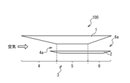
図1は、一実施形態の飛翔体100の構成を示す斜視図である。飛翔体100の機体1にはカウル2が設けられており、機体1及びカウル2にスクラムジェットエンジン3を構成する様々な部材及び機器が搭載されている。
FIG. 1 is a perspective view showing the configuration of the
図2に示すように、スクラムジェットエンジン3は、概略的には、インレット部4と、燃焼器5と、ノズル部6とを備えている。インレット部4は、前方開口4aから超音速の空気を取り込み、取り込んだ空気を圧縮して圧縮空気を生成する。燃焼器5は、インレット部4から圧縮空気を受け取り、該圧縮空気を用いて燃料を燃焼して燃焼ガスを生成する。ノズル部6は、燃焼器5で生成した燃焼ガスを後方開口6aから排出する。燃焼ガスを後方開口6aから排出することにより、飛翔体100の推進力が得られる。
As shown in FIG. 2, the
図3は、燃焼器5の構成を示す断面図である。なお、以下の説明においては、XYZ直交座標系が導入され、該XYZ直交座標系を用いて方向を表現することがある。
FIG. 3 is a cross-sectional view showing the configuration of the
燃焼器5は、カウル2に設けられた燃料噴射装置11、12及び機体1に設けられた燃料噴射装置13を備えており、燃料噴射装置11、12、13によってインレット部4から受け取った圧縮空気に燃料を噴射して燃料を燃焼するように構成されている。
The
本実施形態では、機体1とカウル2との間の空間が燃焼器5の流路20として用いられる。即ち、機体1とカウル2とが、流路20を形成する流路形成部材として用いられる。燃焼器5の流路20は、上流領域21と、乱流形成領域22と、燃焼領域23と、下流領域24とを含んでいる。
In the present embodiment, the space between the
上流領域21は、機体1の面1aとカウル2の面2a(第1面)との間に形成されており、インレット部4で生成された圧縮空気を乱流形成領域22に導入する。本実施形態では、面2aは、燃焼器5の最上流に位置しており、燃焼器5全体としての圧縮空気及び燃焼ガスの流れの方向を規定している。本実施形態では、燃焼器5全体としての圧縮空気及び燃焼ガスの流れの方向は+X方向であり、機体1の面1aとカウル2の面2aは、XZ平面に平行である。上流領域21における流路の高さ、即ち、機体1の面1aとカウル2の面2aの距離は、H1である。
The
乱流形成領域22は、上流領域21の下流に位置している。カウル2の乱流形成領域22に面する部分には、機体1の面1aに向かって突起する突起14が形成されている。図4に示されているように、複数の突起14が、流路20を横断する方向、即ち、Y軸方向に並んで配置されている。突起14は、その下流に乱流を形成する。後述のように、突起14の下流に形成される乱流は、燃焼効率の向上に寄与する。
The
突起14には、燃料ノズル11aが形成されており、燃料噴射装置11は、燃料ノズル11aから突起14の下流に向けて燃料を噴射する。これにより、突起14によって形成された乱流に燃料が噴射される。
A
図3を再度に参照して、突起14の下流側の端にカウル2の面2b(第2面)が接続している。本実施形態では、面2bは、XZ平面に平行である。カウル2の面2bにおける流路20の高さ、即ち、機体1の面1aとカウル2の面2bの距離は、H2である。突起14の下流に位置する面2bにおける流路20の高さH2は、突起14の上流に位置する面2aにおける流路20の高さH1より高い。図4に示されているように、突起14の上流に位置する面2aと、突起14の下流に位置する面2bとは、隣接する突起14の間に形成されたカウル2の面2cによって接続されている。
With reference to FIG. 3 again, the
図3に示すように、燃焼領域23は、乱流形成領域22の下流に位置しており、燃焼領域23では、形成した混合気に着火されて混合気が燃焼される。なお、燃焼領域23は、燃焼が主として行われる領域を意味しているが、他の領域において燃焼が起こらないことを意味しているのではない。例えば、下流領域24の一部でも燃焼は起こり得る。
As shown in FIG. 3, the
カウル2の燃焼領域23に面する部分には、保炎のためにキャビティ15が形成されている。キャビティ15は、突起14の下流に位置する面2bから窪んで形成されており、前壁15aと底面15bと傾斜面15cとを有している。本実施形態では、前壁15aは、その上端が乱流形成領域22に隣接して位置しており、面2bの下流側の端に接続している。本実施形態では、前壁15aは、面2bに垂直(即ち、YZ平面に平行)である。底面15bは、前壁15aの下端に接続されている。本実施形態では、キャビティ15の底面15bは、カウル2の上流領域21に面する面2aと平行(即ち、XZ平面に平行)である。
A
キャビティ15の傾斜面15cは、底面15bの下流側の端に接続している。キャビティ15の傾斜面15cは、面2aと角θ1をなすように(即ち、XZ平面と角θ1をなすように)傾けられている。角θ1は、キャビティランプ角と呼ばれることがある。本実施形態では、キャビティ15の底面15bが面2aと平行なので、結果として、傾斜面15cは、底面15bと角θ1をなすように傾けられていることになる。
The
キャビティ15の傾斜面15cには燃料ノズル12aが形成されており、燃料噴射装置12は、燃料ノズル12aからキャビティ15の内部に向けて燃料を噴射する。更に、キャビティ15の底面15bには、キャビティ15に噴射された燃料に着火する着火装置16が設けられている。
A
下流領域24は、燃焼領域23の下流に位置している。下流領域24は、燃焼器5における燃焼によって発生した燃焼ガスをノズル部6に送り込む。
The
機体1の面1aの下流領域24に面する部分に燃料ノズル13aが設けられており、燃料噴射装置13は、燃料ノズル13aから下流領域24に燃料を噴射する。燃料噴射装置13は、下流領域24において燃料を噴射することによって燃焼ガスの流れを堰き止め、これにより燃焼を促進するために設けられている。
A
下流領域24においては、その少なくとも一部において、流路20の断面積が、下流に向けて大きくなっていてもよい。このような構造は、下流領域24において、カウル2に沿って燃焼ガスをスムーズに下流側に流すことに寄与する。本実施形態のスクラムジェットエンジン3では、燃料噴射装置13による燃料の噴射によって燃焼ガスの流れが過剰に堰き止められると、上流において圧力が過剰に高くなって、空気が取り込めなくなってしまう。下流領域24において流路20の断面積を下流に向けて増大させることで、燃焼ガスをカウル2に沿って下流に流れさせるための空間が確保でき、燃焼ガスをスムーズに噴出することができる。
In the
具体的には、本実施形態では、下流領域24においてカウル2に開き角が設けられている。すなわち、カウル2の下流領域24に面する面2dは、下流に向かって機体1の面1aとカウル2の面2dの間の距離が大きくなるように傾斜している。図2において、機体1の面1aとカウル2の面2dとがなす角は、記号θ2として示されている。これにより、流路20の断面積が下流に向けて大きくなり、これは、燃焼ガスをスムーズに噴出するために有効である。一実施形態では、角θ2は、2°以上、4°以下に設定されてもよい。
Specifically, in the present embodiment, the
図5は、本実施形態の燃焼器5の動作を示す図である。
本実施形態の燃焼器5では、キャビティ15の傾斜面15cの傾きが、燃焼領域23において衝撃波が発生するように調節されており、これにより、燃焼効率が向上されている。ここで、衝撃波の発生は、圧力の不連続面30が形成されることを意味することに留意されたい。本実施形態では、不連続面30が燃焼ガスの流れに対して斜めであり、斜め衝撃波が発生していることになる。
FIG. 5 is a diagram showing the operation of the
In the
キャビティ15は、混合気の流れを遅くすることで内部に循環流を形成し、その循環流に着火することで保炎を実現するように構成される構造体である。このような観点からは、混合気の流れを十分に遅くするために、キャビティランプ角、即ち、傾斜面15cがカウル2の面2aとなす角θ1をある程度大きくとることが一般的である。
The
発明者の発見は、キャビティ15の傾斜面15cの傾きを緩やかにすると、即ち、傾斜面15cが、カウル2の面2aとなす角θ1を小さくすると、キャビティ15の内部における流れを遅くする作用は弱まるが、衝撃波が発生することによりむしろ燃焼が促進されるということである。燃焼領域23に衝撃波が発生すると、燃焼領域23に圧力の不連続面30が形成される。不連続面30の上流側の近傍の領域では、圧力及び温度が上昇し、このような領域で燃焼が行われることで、燃焼効率を有効に向上させることができる。
The inventor's discovery is that when the inclination of the
発明者は、キャビティ15の傾斜面15cがカウル2の面2aとなす角θ1を45°以下にすることが衝撃波の発生に好適であることをシミュレーションにより確認した。更に、傾斜面15cの傾きを衝撃波が発生するように調節することで、燃焼効率を30%程度向上できることを燃焼実験により確認した。なお、傾斜面15cの傾きをカウル2の面2aを基準として表しているのは、カウル2の面2aが、燃焼器5全体としての圧縮空気及び燃焼ガスの流れの向きを決定しているからである。
The inventor has confirmed by simulation that it is suitable for the generation of a shock wave that the angle θ 1 formed by the
一方で、キャビティ15の傾斜面15cが過剰に緩やかであると、流れを遅くする機能が損なわれる。この観点から、キャビティ15の傾斜面15cがカウル2の面2aとなす角θ1は、20°以上であることが好ましい。
On the other hand, if the
以下では、本実施形態の燃焼器5の動作の詳細を説明する。
Hereinafter, the details of the operation of the
インレット部4で生成された圧縮空気は、上流領域21に流れ込み、更に、乱流形成領域22に導入される。
The compressed air generated in the
圧縮空気が乱流形成領域22に導入されると、乱流形成領域22に形成された突起14の列により、突起14の下流に乱流が形成される。更に、突起14に設けられた燃料ノズル11aから突起14の下流に形成された乱流に燃料が噴射され、これにより、混合気が生成される。乱流に燃料を噴射することは、混合気を効率よく生成するために有効である。
When compressed air is introduced into the turbulent
本実施形態の燃焼器5の乱流形成領域22における構造は、混合気の形成の効率を一層に向上させている。本実施形態では、突起14の下流に位置する面2bにおける流路20の高さH2が、突起14の上流に位置する面2aにおける流路20の高さH1より高く、乱流形成領域22の面2bに面する部分における圧力が上流領域21より低くなる。加えて、図4に示されているように、突起14の上流に位置する面2aと、突起14の下流に位置する面2bとは、隣接する突起14の間に形成されたカウル2の面2cによって接続されており、隣接する突起14の間において面2cに沿って圧縮空気の流れが形成される。これにより、乱流の形成が促進され、燃料と圧縮空気とが混ざり合った混合気を効率よく生成できる。
The structure of the
乱流形成領域22で生成された混合気は、燃焼領域23に導入される。混合気の一部は、キャビティ15によって減速され、これにより、キャビティ15に循環流15dが形成される。循環流15dに燃料ノズル12aから燃料が燃料噴射装置12によって噴射され、更に、着火装置16によって循環流15dに着火されることで、キャビティ15に炎が保持される。
The air-fuel mixture generated in the
更に、キャビティ15に保持されている炎によって燃焼領域23に導入された混合気に着火されて混合気が燃焼し、燃焼ガスが生成される。
Further, the flame held in the
上述のように、キャビティ15の傾斜面15cが緩やかに形成されていることで燃焼領域23に衝撃波が発生し、これにより、燃焼領域23に圧力の不連続面30が形成される。不連続面30の上流側の近傍の領域では、圧力及び温度が上昇するので、高い燃焼効率が得られる。
As described above, since the
不連続面30は、キャビティ15の内部にまで到達しており、燃料噴射装置12は、不連続面30の下流の位置から不連続面30の上流の位置に向け、不連続面30を横切るように燃料を噴射する。これは、キャビティ15の内部に発生する循環流15dと燃料の混合を促進し、燃焼効率を向上するために有効である。
The
燃焼領域23で生成された燃焼ガスは、下流領域24に導入される。下流領域24では、燃焼領域23から流れてくる燃焼ガスの流れが、燃料噴射装置13の燃料噴射によって堰き止められ、燃焼ガスの速度が低下する。これにより、燃焼ガスに含まれる未燃焼の燃料の燃焼を促進することができる。燃焼ガスは、下流領域24からノズル部6に導入され、ノズル部6から噴出される。これにより、飛翔体100を推進する推進力が得られる。
The combustion gas generated in the
以上に説明されているように、本実施形態のスクラムジェットエンジン3では、燃焼領域23において衝撃波を発生することで、燃焼ガスの燃焼効率を向上させることができる。
As described above, in the
以上には、本発明の実施形態が具体的に記述されているが、本発明は、上記の実施形態に限定されない。本発明が種々の変更と共に実施され得ることは、当業者には理解されよう。 Although the embodiments of the present invention are specifically described above, the present invention is not limited to the above-described embodiments. Those skilled in the art will appreciate that the present invention can be practiced with various modifications.
例えば、上述の実施形態では、燃料噴射装置13が機体1に設けられ、燃料噴射装置11、12、突起14、キャビティ15、着火装置16がカウル2にあるとして説明を行っているが、これに限定されない。上述の実施形態においてカウル2に設けられると記述されている構成要素が、機体1に設けられ、機体1に設けられると記述されている構成要素が、カウル2に設けられてもよい。
For example, in the above-described embodiment, the
また、十分な燃焼効率が得られるのであれば、下流領域24に燃料を噴射する燃料噴射装置13は設けられなくてもよい。
Further, if sufficient combustion efficiency can be obtained, the
100 :飛翔体
1 :機体
1a :面
2 :カウル
2a~2d:面
3 :スクラムジェットエンジン
4 :インレット部
4a :前方開口
5 :燃焼器
6 :ノズル部
6a :後方開口
11 :燃料噴射装置
11a :燃料ノズル
12 :燃料噴射装置
12a :燃料ノズル
13 :燃料噴射装置
13a :燃料ノズル
14 :突起
15 :キャビティ
15a :前壁
15b :底面
15c :傾斜面
15d :循環流
16 :着火装置
20 :流路
21 :上流領域
22 :乱流形成領域
23 :燃焼領域
24 :下流領域
30 :不連続面
100: Flying object 1:
Claims (7)
前記第1流路形成部材に対向して設けられた第2流路形成部材と、
第1燃料噴射装置と、
第2燃料噴射装置
とを具備し、
前記第1流路形成部材と前記第2流路形成部材との間に流路が形成され、
前記流路が、
上流から圧縮空気が導入される乱流形成領域と、
前記乱流形成領域の下流に位置し、前記圧縮空気を用いた燃焼が行われる燃焼領域
とを含み、
前記第2流路形成部材には、前記乱流形成領域に位置し、前記第1流路形成部材に向かって突起する突起が形成され、
前記第1燃料噴射装置は、前記突起に設けられた第1燃料ノズルを介して前記圧縮空気に燃料を噴射し、
前記第2流路形成部材には、前記燃焼領域に位置するキャビティが形成され、
前記第2燃料噴射装置は、前記キャビティに設けられた第2燃料ノズルを介して前記圧縮空気に燃料を噴射し、
前記キャビティは、
底面と、
前記底面の下流側の端に接続する傾斜面
とを有し、
前記キャビティの前記傾斜面の傾きが、前記燃焼領域に衝撃波が、前記衝撃波の発生により形成される不連続面が前記キャビティの内部に到達するように発生するように調節されており、
前記第2燃料噴射装置は、前記不連続面の下流の位置から前記不連続面の上流の位置に向けて、前記キャビティの内部において前記不連続面を横切るように燃料を噴射する
スクラムジェットエンジン。 The first flow path forming member and
A second flow path forming member provided so as to face the first flow path forming member,
The first fuel injection device and
Equipped with a second fuel injection device,
A flow path is formed between the first flow path forming member and the second flow path forming member.
The flow path
Turbulence formation region where compressed air is introduced from upstream,
It is located downstream of the turbulent flow forming region and includes a combustion region where combustion using the compressed air is performed.
The second flow path forming member is formed with protrusions located in the turbulent flow forming region and projecting toward the first flow path forming member.
The first fuel injection device injects fuel into the compressed air through a first fuel nozzle provided on the protrusion.
A cavity located in the combustion region is formed in the second flow path forming member.
The second fuel injection device injects fuel into the compressed air through a second fuel nozzle provided in the cavity.
The cavity is
With the bottom
It has an inclined surface connected to the downstream end of the bottom surface and has an inclined surface.
The inclination of the inclined surface of the cavity is adjusted so that a shock wave is generated in the combustion region and a discontinuous surface formed by the generation of the shock wave reaches the inside of the cavity .
The second fuel injection device injects fuel from a position downstream of the discontinuity toward a position upstream of the discontinuity so as to cross the discontinuity inside the cavity.
Scramjet engine.
前記流路が、更に、前記圧縮空気を前記乱流形成領域に導入する上流領域を含み、
前記キャビティの前記傾斜面が、前記第2流路形成部材の前記上流領域に面する部分の面である第1面となす角が、45°以下である
スクラムジェットエンジン。 The scramjet engine according to claim 1.
The flow path further comprises an upstream region that introduces the compressed air into the turbulence forming region.
A scramjet engine in which the angle formed by the inclined surface of the cavity with the first surface, which is the surface of the portion of the second flow path forming member facing the upstream region, is 45 ° or less.
前記キャビティの前記傾斜面が前記第2流路形成部材の前記第1面となす角が、20°以上である
スクラムジェットエンジン。 The scramjet engine according to claim 2.
A scramjet engine in which the angle formed by the inclined surface of the cavity with the first surface of the second flow path forming member is 20 ° or more.
前記第2流路形成部材は、前記乱流形成領域の前記突起の下流に位置する第2面を有し、
前記第2面と前記第1流路形成部材との間の距離が、前記第1面と前記第1流路形成部材との間の距離よりも大きい
スクラムジェットエンジン。 The scramjet engine according to claim 2 or 3.
The second flow path forming member has a second surface located downstream of the protrusion in the turbulence forming region.
A scramjet engine in which the distance between the second surface and the first flow path forming member is larger than the distance between the first surface and the first flow path forming member.
前記キャビティの前壁の上端が前記第2面に接続され、
前記キャビティの前記底面の上流側の端が、前記前壁の下端に接続されている
スクラムジェットエンジン。 The scramjet engine according to claim 4 .
The upper end of the front wall of the cavity is connected to the second surface.
A scramjet engine in which the upstream end of the bottom surface of the cavity is connected to the lower end of the front wall.
更に、前記第1流路形成部材の前記キャビティよりも下流の位置に設けられた第3燃料ノズルを介して前記第2流路形成部材に向けて燃料を噴射する第3燃料噴射装置を具備する
スクラムジェットエンジン。 The scramjet engine according to any one of claims 1 to 3 .
Further, the present invention includes a third fuel injection device that injects fuel toward the second flow path forming member via a third fuel nozzle provided at a position downstream of the cavity of the first flow path forming member. Scramjet engine.
Priority Applications (5)
| Application Number | Priority Date | Filing Date | Title |
|---|---|---|---|
| JP2018022332A JP7001489B2 (en) | 2018-02-09 | 2018-02-09 | Scramjet engine and projectile |
| PCT/JP2018/026500 WO2019155654A1 (en) | 2018-02-09 | 2018-07-13 | Scramjet engine and flying object |
| AU2018407616A AU2018407616B2 (en) | 2018-02-09 | 2018-07-13 | Scramjet engine and flying object |
| US16/638,203 US11692514B2 (en) | 2018-02-09 | 2018-07-13 | Scramjet engine and flying object |
| EP18905558.5A EP3647578B1 (en) | 2018-02-09 | 2018-07-13 | Scramjet engine and flying object |
Applications Claiming Priority (1)
| Application Number | Priority Date | Filing Date | Title |
|---|---|---|---|
| JP2018022332A JP7001489B2 (en) | 2018-02-09 | 2018-02-09 | Scramjet engine and projectile |
Publications (2)
| Publication Number | Publication Date |
|---|---|
| JP2019138219A JP2019138219A (en) | 2019-08-22 |
| JP7001489B2 true JP7001489B2 (en) | 2022-01-19 |
Family
ID=67548352
Family Applications (1)
| Application Number | Title | Priority Date | Filing Date |
|---|---|---|---|
| JP2018022332A Active JP7001489B2 (en) | 2018-02-09 | 2018-02-09 | Scramjet engine and projectile |
Country Status (5)
| Country | Link |
|---|---|
| US (1) | US11692514B2 (en) |
| EP (1) | EP3647578B1 (en) |
| JP (1) | JP7001489B2 (en) |
| AU (1) | AU2018407616B2 (en) |
| WO (1) | WO2019155654A1 (en) |
Families Citing this family (2)
| Publication number | Priority date | Publication date | Assignee | Title |
|---|---|---|---|---|
| US11415080B2 (en) * | 2018-05-14 | 2022-08-16 | General Electric Company | Engine for an aircraft |
| CN111664023A (en) * | 2020-07-03 | 2020-09-15 | 中国空气动力研究与发展中心 | Fuel mixing device of scramjet engine |
Citations (12)
| Publication number | Priority date | Publication date | Assignee | Title |
|---|---|---|---|---|
| US5058826A (en) | 1990-01-29 | 1991-10-22 | General Electric Company | Scramjet engine having a low pressure combustion cycle |
| US5202525A (en) | 1990-01-29 | 1993-04-13 | General Electric Company | Scramjet engine having improved fuel/air mixing |
| US20080196414A1 (en) | 2005-03-22 | 2008-08-21 | Andreadis Dean E | Strut cavity pilot and fuel injector assembly |
| JP2012013008A (en) | 2010-07-01 | 2012-01-19 | Mitsubishi Heavy Ind Ltd | Ignition method of supersonic combustor, and ignition control device |
| JP2012013007A (en) | 2010-07-01 | 2012-01-19 | Mitsubishi Heavy Ind Ltd | Supersonic combustor |
| JP2012207555A (en) | 2011-03-29 | 2012-10-25 | Mitsubishi Heavy Ind Ltd | Scramjet engine |
| US20150013305A1 (en) | 2009-11-19 | 2015-01-15 | U.S.A. As Represented By The Administrator Of The National Aeronautics And Space Administration | Dual-Mode Combustor |
| JP2016138725A (en) | 2015-01-28 | 2016-08-04 | 三菱重工業株式会社 | Jet engine, missile and jet engine operating method |
| JP2017160873A (en) | 2016-03-10 | 2017-09-14 | 三菱重工業株式会社 | Scramjet engine and flying object |
| JP2017166410A (en) | 2016-03-16 | 2017-09-21 | 三菱重工業株式会社 | Jet engine, flying body and operation method for jet engine |
| JP2017166409A (en) | 2016-03-16 | 2017-09-21 | 三菱重工業株式会社 | Jet engine and flying object |
| JP2017180109A (en) | 2016-03-28 | 2017-10-05 | 三菱重工業株式会社 | Scramjet engine and flying object |
Family Cites Families (19)
| Publication number | Priority date | Publication date | Assignee | Title |
|---|---|---|---|---|
| US2952123A (en) * | 1956-05-25 | 1960-09-13 | Lockheed Aircraft Corp | Directional controls for propulsive jets |
| JPH0715264B2 (en) * | 1989-01-31 | 1995-02-22 | 日産自動車株式会社 | Supersonic air intake device |
| US5109670A (en) * | 1989-03-23 | 1992-05-05 | General Electric Company | Scramjet combustor |
| US5072582A (en) * | 1989-03-23 | 1991-12-17 | General Electric Company | Scramjet combustor |
| US5072581A (en) * | 1989-03-23 | 1991-12-17 | General Electric Company | Scramjet combustor |
| US5085048A (en) | 1990-02-28 | 1992-02-04 | General Electric Company | Scramjet including integrated inlet and combustor |
| US5253474A (en) * | 1991-08-30 | 1993-10-19 | General Electric Company | Apparatus for supersonic combustion in a restricted length |
| US5791148A (en) * | 1995-06-07 | 1998-08-11 | General Electric Company | Liner of a gas turbine engine combustor having trapped vortex cavity |
| JPH08334213A (en) * | 1995-06-09 | 1996-12-17 | Ishikawajima Harima Heavy Ind Co Ltd | Supersonic combustor and ignition method therefor |
| DE59807195D1 (en) * | 1998-11-06 | 2003-03-20 | Alstom Switzerland Ltd | Flow channel with cross-sectional jump |
| US6286298B1 (en) * | 1998-12-18 | 2001-09-11 | General Electric Company | Apparatus and method for rich-quench-lean (RQL) concept in a gas turbine engine combustor having trapped vortex cavity |
| US6786040B2 (en) * | 2002-02-20 | 2004-09-07 | Space Access, Llc | Ejector based engines |
| JP3994122B2 (en) * | 2002-08-26 | 2007-10-17 | 独立行政法人科学技術振興機構 | Boundary layer separation control device, fuel injector, and control method |
| US20080060361A1 (en) * | 2006-09-07 | 2008-03-13 | Pratt & Whitney Rocketdyne, Inc. | Multi-height ramp injector scramjet combustor |
| KR20090055412A (en) * | 2007-11-28 | 2009-06-02 | 재단법인서울대학교산학협력재단 | Structure for mixing fuel-air by using a cavity in ultrasonic flow field |
| KR101046759B1 (en) * | 2009-12-22 | 2011-07-06 | 한국항공우주연구원 | Combustion Enhancement Flame Insulator for Scramjet Engine Combustor |
| JP5758160B2 (en) * | 2011-03-23 | 2015-08-05 | 三菱重工業株式会社 | Scramjet engine |
| JP2016056692A (en) * | 2014-09-05 | 2016-04-21 | 国立大学法人東北大学 | Combustion apparatus for scramjet engine and scramjet engine |
| JP7054603B2 (en) | 2016-08-03 | 2022-04-14 | ヤフー株式会社 | Judgment device, judgment method, and judgment program |
-
2018
- 2018-02-09 JP JP2018022332A patent/JP7001489B2/en active Active
- 2018-07-13 WO PCT/JP2018/026500 patent/WO2019155654A1/en unknown
- 2018-07-13 US US16/638,203 patent/US11692514B2/en active Active
- 2018-07-13 AU AU2018407616A patent/AU2018407616B2/en active Active
- 2018-07-13 EP EP18905558.5A patent/EP3647578B1/en active Active
Patent Citations (12)
| Publication number | Priority date | Publication date | Assignee | Title |
|---|---|---|---|---|
| US5058826A (en) | 1990-01-29 | 1991-10-22 | General Electric Company | Scramjet engine having a low pressure combustion cycle |
| US5202525A (en) | 1990-01-29 | 1993-04-13 | General Electric Company | Scramjet engine having improved fuel/air mixing |
| US20080196414A1 (en) | 2005-03-22 | 2008-08-21 | Andreadis Dean E | Strut cavity pilot and fuel injector assembly |
| US20150013305A1 (en) | 2009-11-19 | 2015-01-15 | U.S.A. As Represented By The Administrator Of The National Aeronautics And Space Administration | Dual-Mode Combustor |
| JP2012013008A (en) | 2010-07-01 | 2012-01-19 | Mitsubishi Heavy Ind Ltd | Ignition method of supersonic combustor, and ignition control device |
| JP2012013007A (en) | 2010-07-01 | 2012-01-19 | Mitsubishi Heavy Ind Ltd | Supersonic combustor |
| JP2012207555A (en) | 2011-03-29 | 2012-10-25 | Mitsubishi Heavy Ind Ltd | Scramjet engine |
| JP2016138725A (en) | 2015-01-28 | 2016-08-04 | 三菱重工業株式会社 | Jet engine, missile and jet engine operating method |
| JP2017160873A (en) | 2016-03-10 | 2017-09-14 | 三菱重工業株式会社 | Scramjet engine and flying object |
| JP2017166410A (en) | 2016-03-16 | 2017-09-21 | 三菱重工業株式会社 | Jet engine, flying body and operation method for jet engine |
| JP2017166409A (en) | 2016-03-16 | 2017-09-21 | 三菱重工業株式会社 | Jet engine and flying object |
| JP2017180109A (en) | 2016-03-28 | 2017-10-05 | 三菱重工業株式会社 | Scramjet engine and flying object |
Also Published As
| Publication number | Publication date |
|---|---|
| EP3647578B1 (en) | 2024-02-14 |
| US11692514B2 (en) | 2023-07-04 |
| WO2019155654A1 (en) | 2019-08-15 |
| EP3647578A1 (en) | 2020-05-06 |
| AU2018407616B2 (en) | 2021-05-20 |
| JP2019138219A (en) | 2019-08-22 |
| EP3647578A4 (en) | 2020-07-22 |
| US20200362795A1 (en) | 2020-11-19 |
| AU2018407616A1 (en) | 2020-02-27 |
Similar Documents
| Publication | Publication Date | Title |
|---|---|---|
| US4903480A (en) | Hypersonic scramjet engine fuel injector | |
| JPH04219452A (en) | Scram jet with combustion apparatus unified with inlet | |
| JP6719933B2 (en) | Jet engine, flying body, and how to operate jet engine | |
| CN106968834B (en) | A kind of supersonic speed detonation engine and its propulsion system | |
| JP7001489B2 (en) | Scramjet engine and projectile | |
| JPH09324700A (en) | Fuel injection device for ram jet | |
| US10190539B2 (en) | Inlet flow restrictor | |
| JP5791323B2 (en) | Scramjet engine | |
| WO2015146357A1 (en) | Combustor, jet engine, flying body, and method for operating jet engine | |
| JP6688637B2 (en) | Scrumjet engine, flying object | |
| JP6788522B2 (en) | Scramjet engine | |
| KR101320625B1 (en) | Scramjet Engine | |
| RU2604975C2 (en) | Hypersonic aircraft with ramjet with increased flight and technical characteristics | |
| WO2017158856A1 (en) | Jet engine and flying object | |
| KR101954034B1 (en) | Supersonic fuel injection apparatus | |
| JP2017180109A (en) | Scramjet engine and flying object | |
| JP2014122607A (en) | Scramjet engine and combustion control method | |
| JPH05272411A (en) | Scram jet engine | |
| JP3042206B2 (en) | Scrumjet engine | |
| KR20180019815A (en) | Dual Mode Ramjet Engine | |
| US4969327A (en) | Hypersonic scramjet engine fuel injector | |
| JP2712830B2 (en) | Mixed combustor | |
| JPH08165952A (en) | Fluid mixing device for jet engine | |
| JPH06280679A (en) | Combustor and method for maintaining flame of the same | |
| KR20100046754A (en) | Linear ram jet engiene and coaxial counter-rotating rotor plane using thereof |
Legal Events
| Date | Code | Title | Description |
|---|---|---|---|
| RD04 | Notification of resignation of power of attorney |
Free format text: JAPANESE INTERMEDIATE CODE: A7424 Effective date: 20191209 |
|
| A621 | Written request for application examination |
Free format text: JAPANESE INTERMEDIATE CODE: A621 Effective date: 20201210 |
|
| A131 | Notification of reasons for refusal |
Free format text: JAPANESE INTERMEDIATE CODE: A131 Effective date: 20210616 |
|
| A521 | Request for written amendment filed |
Free format text: JAPANESE INTERMEDIATE CODE: A523 Effective date: 20210804 |
|
| TRDD | Decision of grant or rejection written | ||
| A01 | Written decision to grant a patent or to grant a registration (utility model) |
Free format text: JAPANESE INTERMEDIATE CODE: A01 Effective date: 20211208 |
|
| A61 | First payment of annual fees (during grant procedure) |
Free format text: JAPANESE INTERMEDIATE CODE: A61 Effective date: 20211224 |
|
| R150 | Certificate of patent or registration of utility model |
Ref document number: 7001489 Country of ref document: JP Free format text: JAPANESE INTERMEDIATE CODE: R150 |