JP6719933B2 - Jet engine, flying body, and how to operate jet engine - Google Patents
Jet engine, flying body, and how to operate jet engine Download PDFInfo
- Publication number
- JP6719933B2 JP6719933B2 JP2016052186A JP2016052186A JP6719933B2 JP 6719933 B2 JP6719933 B2 JP 6719933B2 JP 2016052186 A JP2016052186 A JP 2016052186A JP 2016052186 A JP2016052186 A JP 2016052186A JP 6719933 B2 JP6719933 B2 JP 6719933B2
- Authority
- JP
- Japan
- Prior art keywords
- air
- injection port
- air flow
- fuel injection
- turbulent
- Prior art date
- Legal status (The legal status is an assumption and is not a legal conclusion. Google has not performed a legal analysis and makes no representation as to the accuracy of the status listed.)
- Active
Links
Images


Classifications
-
- F—MECHANICAL ENGINEERING; LIGHTING; HEATING; WEAPONS; BLASTING
- F02—COMBUSTION ENGINES; HOT-GAS OR COMBUSTION-PRODUCT ENGINE PLANTS
- F02K—JET-PROPULSION PLANTS
- F02K7/00—Plants in which the working fluid is used in a jet only, i.e. the plants not having a turbine or other engine driving a compressor or a ducted fan; Control thereof
- F02K7/10—Plants in which the working fluid is used in a jet only, i.e. the plants not having a turbine or other engine driving a compressor or a ducted fan; Control thereof characterised by having ram-action compression, i.e. aero-thermo-dynamic-ducts or ram-jet engines
-
- F—MECHANICAL ENGINEERING; LIGHTING; HEATING; WEAPONS; BLASTING
- F23—COMBUSTION APPARATUS; COMBUSTION PROCESSES
- F23R—GENERATING COMBUSTION PRODUCTS OF HIGH PRESSURE OR HIGH VELOCITY, e.g. GAS-TURBINE COMBUSTION CHAMBERS
- F23R3/00—Continuous combustion chambers using liquid or gaseous fuel
- F23R3/02—Continuous combustion chambers using liquid or gaseous fuel characterised by the air-flow or gas-flow configuration
- F23R3/16—Continuous combustion chambers using liquid or gaseous fuel characterised by the air-flow or gas-flow configuration with devices inside the flame tube or the combustion chamber to influence the air or gas flow
- F23R3/18—Flame stabilising means, e.g. flame holders for after-burners of jet-propulsion plants
- F23R3/22—Flame stabilising means, e.g. flame holders for after-burners of jet-propulsion plants movable, e.g. to an inoperative position; adjustable, e.g. self-adjusting
-
- F—MECHANICAL ENGINEERING; LIGHTING; HEATING; WEAPONS; BLASTING
- F02—COMBUSTION ENGINES; HOT-GAS OR COMBUSTION-PRODUCT ENGINE PLANTS
- F02C—GAS-TURBINE PLANTS; AIR INTAKES FOR JET-PROPULSION PLANTS; CONTROLLING FUEL SUPPLY IN AIR-BREATHING JET-PROPULSION PLANTS
- F02C7/00—Features, components parts, details or accessories, not provided for in, or of interest apart form groups F02C1/00 - F02C6/00; Air intakes for jet-propulsion plants
- F02C7/04—Air intakes for gas-turbine plants or jet-propulsion plants
- F02C7/057—Control or regulation
-
- F—MECHANICAL ENGINEERING; LIGHTING; HEATING; WEAPONS; BLASTING
- F02—COMBUSTION ENGINES; HOT-GAS OR COMBUSTION-PRODUCT ENGINE PLANTS
- F02C—GAS-TURBINE PLANTS; AIR INTAKES FOR JET-PROPULSION PLANTS; CONTROLLING FUEL SUPPLY IN AIR-BREATHING JET-PROPULSION PLANTS
- F02C7/00—Features, components parts, details or accessories, not provided for in, or of interest apart form groups F02C1/00 - F02C6/00; Air intakes for jet-propulsion plants
- F02C7/26—Starting; Ignition
-
- F—MECHANICAL ENGINEERING; LIGHTING; HEATING; WEAPONS; BLASTING
- F23—COMBUSTION APPARATUS; COMBUSTION PROCESSES
- F23R—GENERATING COMBUSTION PRODUCTS OF HIGH PRESSURE OR HIGH VELOCITY, e.g. GAS-TURBINE COMBUSTION CHAMBERS
- F23R3/00—Continuous combustion chambers using liquid or gaseous fuel
- F23R3/02—Continuous combustion chambers using liquid or gaseous fuel characterised by the air-flow or gas-flow configuration
- F23R3/04—Air inlet arrangements
- F23R3/10—Air inlet arrangements for primary air
-
- F—MECHANICAL ENGINEERING; LIGHTING; HEATING; WEAPONS; BLASTING
- F23—COMBUSTION APPARATUS; COMBUSTION PROCESSES
- F23R—GENERATING COMBUSTION PRODUCTS OF HIGH PRESSURE OR HIGH VELOCITY, e.g. GAS-TURBINE COMBUSTION CHAMBERS
- F23R3/00—Continuous combustion chambers using liquid or gaseous fuel
- F23R3/02—Continuous combustion chambers using liquid or gaseous fuel characterised by the air-flow or gas-flow configuration
- F23R3/16—Continuous combustion chambers using liquid or gaseous fuel characterised by the air-flow or gas-flow configuration with devices inside the flame tube or the combustion chamber to influence the air or gas flow
- F23R3/18—Flame stabilising means, e.g. flame holders for after-burners of jet-propulsion plants
- F23R3/20—Flame stabilising means, e.g. flame holders for after-burners of jet-propulsion plants incorporating fuel injection means
-
- F—MECHANICAL ENGINEERING; LIGHTING; HEATING; WEAPONS; BLASTING
- F23—COMBUSTION APPARATUS; COMBUSTION PROCESSES
- F23R—GENERATING COMBUSTION PRODUCTS OF HIGH PRESSURE OR HIGH VELOCITY, e.g. GAS-TURBINE COMBUSTION CHAMBERS
- F23R3/00—Continuous combustion chambers using liquid or gaseous fuel
- F23R3/28—Continuous combustion chambers using liquid or gaseous fuel characterised by the fuel supply
-
- F—MECHANICAL ENGINEERING; LIGHTING; HEATING; WEAPONS; BLASTING
- F05—INDEXING SCHEMES RELATING TO ENGINES OR PUMPS IN VARIOUS SUBCLASSES OF CLASSES F01-F04
- F05D—INDEXING SCHEME FOR ASPECTS RELATING TO NON-POSITIVE-DISPLACEMENT MACHINES OR ENGINES, GAS-TURBINES OR JET-PROPULSION PLANTS
- F05D2210/00—Working fluids
- F05D2210/30—Flow characteristics
- F05D2210/33—Turbulent flow
-
- F—MECHANICAL ENGINEERING; LIGHTING; HEATING; WEAPONS; BLASTING
- F05—INDEXING SCHEMES RELATING TO ENGINES OR PUMPS IN VARIOUS SUBCLASSES OF CLASSES F01-F04
- F05D—INDEXING SCHEME FOR ASPECTS RELATING TO NON-POSITIVE-DISPLACEMENT MACHINES OR ENGINES, GAS-TURBINES OR JET-PROPULSION PLANTS
- F05D2220/00—Application
- F05D2220/10—Application in ram-jet engines or ram-jet driven vehicles
-
- F—MECHANICAL ENGINEERING; LIGHTING; HEATING; WEAPONS; BLASTING
- F05—INDEXING SCHEMES RELATING TO ENGINES OR PUMPS IN VARIOUS SUBCLASSES OF CLASSES F01-F04
- F05D—INDEXING SCHEME FOR ASPECTS RELATING TO NON-POSITIVE-DISPLACEMENT MACHINES OR ENGINES, GAS-TURBINES OR JET-PROPULSION PLANTS
- F05D2240/00—Components
- F05D2240/35—Combustors or associated equipment
-
- F—MECHANICAL ENGINEERING; LIGHTING; HEATING; WEAPONS; BLASTING
- F05—INDEXING SCHEMES RELATING TO ENGINES OR PUMPS IN VARIOUS SUBCLASSES OF CLASSES F01-F04
- F05D—INDEXING SCHEME FOR ASPECTS RELATING TO NON-POSITIVE-DISPLACEMENT MACHINES OR ENGINES, GAS-TURBINES OR JET-PROPULSION PLANTS
- F05D2250/00—Geometry
- F05D2250/50—Inlet or outlet
- F05D2250/51—Inlet
-
- F—MECHANICAL ENGINEERING; LIGHTING; HEATING; WEAPONS; BLASTING
- F05—INDEXING SCHEMES RELATING TO ENGINES OR PUMPS IN VARIOUS SUBCLASSES OF CLASSES F01-F04
- F05D—INDEXING SCHEME FOR ASPECTS RELATING TO NON-POSITIVE-DISPLACEMENT MACHINES OR ENGINES, GAS-TURBINES OR JET-PROPULSION PLANTS
- F05D2270/00—Control
- F05D2270/30—Control parameters, e.g. input parameters
- F05D2270/306—Mass flow
- F05D2270/3061—Mass flow of the working fluid
-
- F—MECHANICAL ENGINEERING; LIGHTING; HEATING; WEAPONS; BLASTING
- F23—COMBUSTION APPARATUS; COMBUSTION PROCESSES
- F23R—GENERATING COMBUSTION PRODUCTS OF HIGH PRESSURE OR HIGH VELOCITY, e.g. GAS-TURBINE COMBUSTION CHAMBERS
- F23R2900/00—Special features of, or arrangements for continuous combustion chambers; Combustion processes therefor
- F23R2900/00015—Trapped vortex combustion chambers
Description
本発明は、ジェットエンジン、飛しょう体、および、ジェットエンジンの動作方法に関する。 The present invention relates to a jet engine, a flying body, and a method of operating a jet engine.
音速より速く飛しょうする機体のジェットエンジンとして、ターボジェットエンジン(ターボファンエンジン等を含む)、ラムジェットエンジン、スクラムジェットエンジンが知られている。これらは空気を取り入れて作動するジェットエンジンであり、特にラムジェットエンジン、スクラムジェットエンジンでは取り入れた空気の速度は飛しょう速度に強く依存する。 Turbojet engines (including turbofan engines, etc.), ramjet engines, and scramjet engines are known as jet engines for aircraft that fly faster than the speed of sound. These are jet engines that operate by taking in air, and especially in ramjet engines and scramjet engines, the speed of the taken air strongly depends on the flight speed.
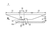
図1A及び図1Bは、ジェットエンジンの構成を模式的に示す概略断面図である。ただし、図1Aは飛しょう速度が遅い場合、図1Bは飛しょう速度が速い場合をそれぞれ示している。ジェットエンジン102は、機体110と、機体110の下方に気体の流通可能な空間150を形成するように設けられたカウル140とを備えている。機体110の前方の下方部分とカウル140の前方部分とは、空間150へ空気を導入するインレット111を構成している。機体110の中間の下方部分とカウル140の中間部分とは、燃料と空気とを混合し燃焼させる燃焼器112を構成している。機体110の後方の下方部分とカウル140の後方部分とは、燃焼気体を膨張させて放出するノズル113を構成している。燃焼器112は、燃料噴射器120と、保炎器121とを備えている。燃料噴射器120は、機体110の下方部分の燃焼器112に対応する部分に設けられている。燃料噴射器120は、空間150へ向けて燃料Gを噴出する。保炎器121は、機体110の下方部分の燃焼器112に対応する部分における、燃料噴射器120よりも後方に設けられている。保炎器121は、燃料噴射器120からの燃料Gを利用して、燃焼用の炎Fを維持する。ジェットエンジン102は、インレット111から取り入れた空気と、燃料噴射器120から噴射した燃料Gとを燃焼器112で混合して燃焼させ、その燃焼ガスをノズル113で膨張させて、機体110の後方へ送出する。保炎器121の炎Fは、その燃焼の維持に用いられる。
1A and 1B are schematic cross-sectional views schematically showing the configuration of a jet engine. However, FIG. 1A shows the case where the flight speed is slow, and FIG. 1B shows the case where the flight speed is fast. The
燃焼器112における保炎器121の前方では、高圧領域HPが形成される。高圧領域HPの広さは主として燃焼器112での燃焼の燃焼圧とインレット111で取り入れた空気の動圧とのバランスによって決定される。飛しょう速度が速く(主に、飛しょう体の巡航段階にあたる)空気の動圧が高い場合では(図1B)、高圧領域HPは狭くなる。一方、飛しょう速度が遅く(概ね飛しょう体の加速段階にあたる)空気の動圧が低い場合では、高圧領域HPは広くなる(図1A)。
A high pressure region HP is formed in front of the
なお、高圧領域HPにおいては、インレット111から取り入れられた空気の流れは、燃焼器の壁面から剥離するか、あるいは、燃焼器の壁面から剥離し易い。
In the high pressure region HP, the flow of air taken in from the
関連する技術として、特許文献1(特開2002−79996号公報)には、空気力学的表面における流れの剥離とそれに関連する現象の抑制方法が開示されている。特許文献1に記載の抑制方法は、物体に沿う流体の流れが物体表面から剥離することを抑制することを目的とする。特許文献1には、バリアー部材を、物体表面に設置することが記載されている。バリアー部材は、物体表面の近傍の剥離流れ層内に配置される。
As a related technique, Japanese Patent Application Laid-Open No. 2002-79996 discloses a method of suppressing flow separation on an aerodynamic surface and a phenomenon related thereto. The suppression method described in
また、特許文献2(特開2012−41821号公報)には、翼体が記載されている。特許文献2では、翼の負圧面における流れの剥離を、最小限の流動抵抗で効果的に抑制することを目的としている。特許文献2には、翼の負圧面の前縁部に複数の切欠段差部を設け、当該切欠段差部の後方に、複数の突起部を設けることが記載されている。
Further, in Patent Document 2 (JP 2012-41821A), a wing body is described.
飛しょう速度が遅く、高圧領域HPが前方に伸びてインレット111に及んだ場合(図1A)、空間150内に向けて十分な空気が供給されず、ジェットエンジン102の推力の低下が発生しうる。
When the flight speed is slow and the high-pressure region HP extends forward and reaches the inlet 111 (FIG. 1A), sufficient air is not supplied into the
そこで、その事態に対処するために、以下のような解決方法が考えられる。図2A及び図2Bは、その解決方法を適用したジェットエンジンの構成を模式的に示す概略断面図である。ただし、図2Aは飛しょう速度が遅い場合、図2Bは飛しょう速度が速い場合をそれぞれ示している。これらの図のジェットエンジン102aでは、図1A及び図1Bのジェットエンジン102と比較して、保炎器121aをより下流に設置している。言い換えると、ジェットエンジン102aでは、燃焼器112aにおいて、保炎器121aよりも前方の長さを長くしている。これは、飛しょう速度が遅い場合でも、高圧領域HPがインレット111に到達しないような長さを基準としているからである。このとき、飛しょう速度が速い場合での燃焼時間を確保するために、保炎器121aよりも後方の長さは変更せず維持している。すなわち、この解決方法は、保炎器121aの前方の長さを長くし、その分だけ、燃焼器112a全体の長さを延長する方法である。
Therefore, in order to deal with the situation, the following solutions can be considered. 2A and 2B are schematic cross-sectional views schematically showing the configuration of a jet engine to which the solution is applied. However, FIG. 2A shows the case where the flight speed is slow, and FIG. 2B shows the case where the flight speed is fast. In the
これにより、飛しょう速度が遅い場合でも(図2A)、高圧領域HPがインレット111に及ぶことは無くなり、ジェットエンジン102aの推力の低下が起こる事態を防止できる。ただし、ジェットエンジン102aの全長を変更しないとすると、燃焼器112aの長さが長くなった分だけ、ノズル113の長さを短くする必要がある。しかし、そうなると、ジェットエンジン102aは作動するものの、機軸方向に推力を得ることが困難となり、正味推力が低下するという問題が発生する。あるいは、機軸方向に推力を得るためにノズル113を十分長くしたり、大きくしたりした場合には、機体110aが大型化するという問題が更に発生する。
As a result, even when the flight speed is low (FIG. 2A), the high pressure region HP does not reach the
したがって、本発明の目的は、機体を大きく改造することなく、高圧領域がインレットへ到達することによるジェットエンジンの推力低下を防止可能なジェットエンジン、飛しょう体及びジェットエンジンの動作方法を提供することにある。 Therefore, an object of the present invention is to provide a jet engine, a flying body, and an operating method of a jet engine capable of preventing the thrust reduction of the jet engine due to the high pressure region reaching the inlet without significantly modifying the aircraft. It is in.
この発明のこれらの目的とそれ以外の目的と利益とは以下の説明と添付図面とによって容易に確認することができる。 These and other objects and benefits of the present invention can be easily confirmed by the following description and the accompanying drawings.
以下に、発明を実施するための形態で使用される番号・符号を用いて、課題を解決するための手段を説明する。これらの番号・符号は、特許請求の範囲の記載と発明を実施するための形態との対応関係の一例を示すために、参考として、括弧付きで付加されたものである。よって、括弧付きの記載により、特許請求の範囲は、限定的に解釈されるべきではない。 The means for solving the problems will be described below by using the numbers and symbols used in the embodiments for carrying out the invention. These numbers and reference numerals are added in parentheses as a reference in order to show an example of the correspondence between the description of the claims and the modes for carrying out the invention. Therefore, the description in parentheses should not be construed as limiting the scope of the claims.
いくつかの実施形態におけるジェットエンジンは、空気を取り込むインレット(11)と、燃料を噴射する燃料噴射口(30a)を備え、前記空気を用いて前記燃料噴射口(30a)から噴射される燃料を燃焼する燃焼器(12)とを具備する。前記燃焼器(12)は、前記インレットの後端(15)と前記燃料噴射口(30a)との間において、前記空気が流れる空気流路(FA)を規定する分離部(14)を備える。前記分離部(14)には、前記空気の流れを乱流化する複数の乱流生成部(20;25)が配置される。前記複数の乱流生成部(20;25)の各々は、移動するか消失することにより前記空気の流れの乱流化を抑制することが可能な部材(21;22;25B)を含む。 The jet engine in some embodiments includes an inlet (11) that takes in air and a fuel injection port (30a) that injects fuel, and uses the air to inject fuel injected from the fuel injection port (30a). A combustor (12) for combusting. The combustor (12) includes a separator (14) that defines an air flow path (FA) through which the air flows between the rear end (15) of the inlet and the fuel injection port (30a). A plurality of turbulent flow generators (20; 25) that make the air flow turbulent are arranged in the separation unit (14). Each of the plurality of turbulent flow generation sections (20; 25) includes a member (21; 22; 25B) capable of suppressing the turbulent flow of the air by moving or disappearing.
上記ジェットエンジンにおいて、前記部材(21;22;25B)は、前記空気流路(FA)に向かって突出する突起を含んでいてもよい。 In the above jet engine, the member (21; 22; 25B) may include a protrusion protruding toward the air passage (FA).
上記ジェットエンジンにおいて、前記部材(21)は、飛しょう中の熱的影響又は空力的影響により前記分離部の壁面上から消失する材料を含んでいてもよい。 In the jet engine, the member (21) may include a material that disappears from the wall surface of the separation portion due to thermal influence or aerodynamic influence during flight.
上記ジェットエンジンにおいて、前記部材(21)が配置される前記分離部(14)の壁面上の位置は、前記空気流路(FA)を流れる前記空気の流れの方向にみて、前記燃料噴射口(30a)が配置される位置とオーバーラップしなくてもよい。 In the above jet engine, the position on the wall surface of the separation portion (14) where the member (21) is arranged is the fuel injection port (when viewed in the flow direction of the air flowing through the air flow path (FA)). It does not have to overlap with the position where 30a) is arranged.
上記ジェットエンジンにおいて、前記燃焼器(12)は、前記燃料噴射口(30a)が配置された第1壁面(16A)と、前記複数の乱流生成部(20)が配置された第2壁面(16B)とを備えていてもよい。前記第2壁面(16B)は、前記第1壁面(16A)とは異なる壁面であってもよい。 In the jet engine, the combustor (12) has a first wall surface (16A) on which the fuel injection port (30a) is arranged and a second wall surface (16A) on which the plurality of turbulent flow generators (20) are arranged. 16B). The second wall surface (16B) may be a wall surface different from the first wall surface (16A).
上記ジェットエンジンにおいて、前記部材(22;25B)は、前記空気流路(FA)に対して移動可能な移動可能部材(22;25B)であってもよい。 In the above jet engine, the member (22; 25B) may be a movable member (22; 25B) movable with respect to the air flow path (FA).
上記ジェットエンジンにおいて、前記移動可能部材(25B)は、飛しょう中の熱的影響又は空力的影響により自動的に移動するように構成されていてもよい。 In the jet engine, the movable member (25B) may be configured to automatically move due to thermal influence or aerodynamic influence during flight.
上記ジェットエンジンにおいて、前記移動可能部材(22)を移動させる駆動装置(23)と、前記駆動装置(23)を制御する制御装置(80)とを更に備えていてもよい。前記制御装置(80)は、飛しょうマッハ数、飛しょう高度、および、飛しょう時間の少なくとも1つに基づいて、前記駆動装置(23)を作動させてもよい。前記駆動装置(23)は、作動することにより、前記移動可能部材(22)の前記空気流路(FA)に対する進出状態あるいは退避状態を変化させてもよい。 The jet engine may further include a drive device (23) for moving the movable member (22) and a control device (80) for controlling the drive device (23). The control device (80) may operate the drive device (23) based on at least one of the flight Mach number, the flight altitude, and the flight time. The drive device (23) may change the advanced state or the retracted state of the movable member (22) with respect to the air flow path (FA) by operating.
上記ジェットエンジンにおいて、前記燃焼器(12)は、保炎器(32)を備えていてもよい。前記移動可能部材(22)が配置される位置は、前記空気流路(FA)を流れる前記空気の流れの方向にみて、前記保炎器(32)が配置される位置とオーバーラップしていてもよい。 In the jet engine, the combustor (12) may include a flame stabilizer (32). The position where the movable member (22) is arranged overlaps with the position where the flame stabilizer (32) is arranged when viewed in the flow direction of the air flowing through the air flow path (FA). Good.
いくつかの実施形態における飛しょう体は、上述のいずれかの段落に記載のジェットエンジンを備える。 The flying vehicle in some embodiments comprises a jet engine as described in any of the paragraphs above.
いくつかの実施形態におけるジェットエンジンの動作方法は、空気を取り込むインレット(11)と、燃料を噴射する燃料噴射口(30a)を備え、前記空気を用いて前記燃料噴射口(30a)から噴射される燃料を燃焼する燃焼器(12)とを具備するジェットエンジンの動作方法である。前記燃焼器(12)は、前記インレットの後端(15)と前記燃料噴射口(30a)との間において、前記空気が流れる空気流路(FA)を規定する分離部(14)を備える。前記分離部(14)には、前記空気の流れを乱流化する複数の乱流生成部(20)が配置される。前記ジェットエンジン(2)の動作方法は、前記複数の乱流生成部(20)により、前記分離部(14)の壁面上の前記空気の流れを乱流化しつつ、前記空気を用いて前記燃料噴射口(30a)から噴射される燃料を燃焼する工程と、前記複数の乱流生成部(20)の各々を構成する部材(21;22;25A)の少なくとも一部を消失または移動させる工程と、前記分離部(14)の壁面上の前記空気の流れの乱流化を抑制しつつ、前記空気を用いて前記燃料噴射口(30a)から噴射される燃料を燃焼する工程とを具備する。 The method of operating a jet engine in some embodiments includes an inlet (11) for taking in air and a fuel injection port (30a) for injecting fuel, the air being used to inject from the fuel injection port (30a). And a combustor (12) for combusting fuel. The combustor (12) includes a separator (14) that defines an air flow path (FA) through which the air flows between the rear end (15) of the inlet and the fuel injection port (30a). A plurality of turbulent flow generators (20) that make the air flow turbulent are arranged in the separation unit (14). The operation method of the jet engine (2) is such that the plurality of turbulent flow generation sections (20) make the flow of the air on the wall surface of the separation section (14) turbulent, and the fuel is produced by using the air. A step of burning the fuel injected from the injection port (30a), and a step of eliminating or moving at least a part of the members (21; 22; 25A) constituting each of the plurality of turbulent flow generation sections (20). Combusting the fuel injected from the fuel injection port (30a) with the air while suppressing the turbulence of the flow of the air on the wall surface of the separation part (14).
本発明により、機体を大きく改造することなく、高圧領域がインレットへ到達することによるジェットエンジンの推力低下を防止可能なジェットエンジン、飛しょう体及びジェットエンジンの動作方法が提供できる。 INDUSTRIAL APPLICABILITY The present invention can provide a jet engine, a flying body, and a method of operating a jet engine that can prevent the thrust of the jet engine from decreasing due to the high-pressure region reaching the inlet without significantly modifying the airframe.
以下、実施形態に係るジェットエンジンに関して、添付図面を参照して説明する。ここでは、ジェットエンジンを飛しょう体に適用した例について説明する。 Hereinafter, a jet engine according to an embodiment will be described with reference to the accompanying drawings. Here, an example in which the jet engine is applied to a flying object will be described.
(方向の定義)
インレットからジェットエンジンに取り込まれる空気の流れに対して上流側、すなわち、ジェットエンジンのインレット側を「上流側」又は「前方側」と定義する。また、インレットからジェットエンジンに取り込まれる空気の流れに対して下流側、すなわち、ジェットエンジンのノズル側を「下流側」又は「後方側」と定義する。また、ジェットエンジンが水平状態にあると仮定した時、燃焼器の長手方向に直交するとともに、鉛直方向に直交する方向を、「スパン方向」と定義する。
(Definition of direction)
The upstream side of the flow of air taken into the jet engine from the inlet, that is, the inlet side of the jet engine is defined as "upstream side" or "front side". Further, the downstream side of the flow of air taken into the jet engine from the inlet, that is, the nozzle side of the jet engine is defined as “downstream side” or “rear side”. Further, when it is assumed that the jet engine is in a horizontal state, a direction that is orthogonal to the longitudinal direction of the combustor and orthogonal to the vertical direction is defined as "span direction".
(飛しょう体の構成概要)
実施形態に係る飛しょう体1の構成について説明する。図3は、実施形態に係る飛しょう体1の構成の一例を示す斜視図である。飛しょう体1は、ジェットエンジン2と、ロケットモータ3とを具備している。ロケットモータ3は、飛しょう体1を発射装置から飛しょうさせるとき、飛しょう体1を飛しょう開始時の速度から所望の速度まで加速する。ただし、飛しょう開始時の速度は、飛しょう体1が静止している発射装置から発射されるときは、速度ゼロであり、飛しょう体が移動中または飛行中の移動体または飛行体の発射装置から発射されるときは、その移動体または飛行体の移動速度または飛行速度である。ジェットエンジン2は、飛しょう体1がロケットモータ3を分離した後、飛しょう体1を更に加速して、目標へ向かって飛しょうさせる。ジェットエンジン2は、機体10とカウル40とを備えている。機体10とカウル40とは、後述されるように、ジェットエンジン2のインレット、燃焼器及びノズルを構成している。ジェットエンジン2は、インレットにて前方から空気を取り入れ、燃焼器にてその空気と燃料とを混合し、燃焼させ、ノズルにてその燃焼ガスを膨張させ、後方へ送出する。それにより、ジェットエンジン2は推進力を得る。飛しょう体1は、センサ60、および/または、制御装置80を備えていてもよい。
(Outline of flight structure)
The configuration of the flying
(ジェットエンジンの構成概要)
次に、図4A乃至図4Dを参照して、実施形態に係るジェットエンジンについて説明する。図4Aおよび図4Cは、実施形態に係るジェットエンジンの構成の一例を模式的に示す概略断面図(縦断面図)である。図4Bは、実施形態に係るジェットエンジンの構成の一例を模式的に示す概略斜視図である。また、図4Cは、図4AのA−A矢視断面図である。
(Outline of jet engine configuration)
Next, a jet engine according to the embodiment will be described with reference to FIGS. 4A to 4D. 4A and 4C are schematic cross-sectional views (longitudinal cross-sectional views) schematically showing an example of the configuration of the jet engine according to the embodiment. FIG. 4B is a schematic perspective view schematically showing an example of the configuration of the jet engine according to the embodiment. 4C is a sectional view taken along the line AA of FIG. 4A.
ジェットエンジン2は、機体10と、機体10の下方に気体の流通可能な空間50を形成するように設けられたカウル40とを備えている。機体10の前方の下方部分とカウル40の前方部分とは、空間50へ空気を導入するインレット11を構成している。機体10の中間の下方部分とカウル40の中間部分とは、燃料と空気とを混合し燃焼させる燃焼器12を構成している。機体10の後方の下方部分とカウル40の後方部分とは、燃焼気体を膨張させて放出するノズル13を構成している。
The
代替的に、例えば、円筒状部材等の筒状部材によってジェットエンジン2を構成し、当該筒状部材(ジェットエンジン2)が機体10の下部に取り付けられてもよい。この場合、筒状部材の前方部分がインレット11を構成し、筒状部材の中間部分が燃焼器12を構成し、筒状部材の後方部分がノズル13を構成する。
Alternatively, for example, the
(燃焼器の構成概要)
燃焼器12は、燃料噴射器30と、保炎器32とを備えている。燃料噴射器30は、保炎器32よりも上流側に配置される。換言すれば、燃料噴射器30は、インレットの後方端15(例えば、ジェットエンジン中の空気の流れ方向に見て、空気流路の断面積の減少が終わる位置)と、保炎器32との間に配置される。代替的に、燃料噴射器30は、保炎器32の壁部内に配置されてもよい。燃料噴射器30は、例えば、複数の燃料噴射口30aを備える。複数の燃料噴射口30aは、例えば、燃焼器12の長手方向に直交する方向(図4A〜図4Bの例では、スパン方向。断面円形の燃焼器を採用する場合には円の周方向。)に沿って、1列または複数列で配置される。
(Outline of combustor configuration)
The combustor 12 includes a
保炎器32は、例えば、燃料噴射器30の下流側に配置される。保炎器32には、主流空気MAと燃料噴射器30から噴射される燃料との混合気体が供給される。混合気体は、保炎器32内においては、低速で移動する。保炎器32は、燃料噴射器30から噴射される燃料の燃焼に用いる炎を維持する。保炎器32は、例えば、燃焼器12の壁部に設けられた凹部(浅い凹部)である。凹部は、燃焼器12のスパン方向全体にわたって形成されてもよい。代替的に、凹部は、燃焼器12のスパン方向の一部のみにわたって形成されてもよい。図4A、図4Bの例では、凹部の断面形状(スパン方向に垂直な面における断面形状)は、矩形形状である。代替的に、凹部の断面形状は、矩形形状以外の形状であってもよい。
The
燃焼器12は、インレットの後方端15と、燃料噴射器30(例えば、燃料噴射口30a)との間において、インレット11から取り込まれた空気が流れる空気流路FAを規定する分離部14を備える。
The combustor 12 includes a separating
図4Cには、図4AのA−A矢視断面図が記載されている。図4Cを参照すると、分離部14によって、空気流路FAが規定されていることが把握される。また、図4A、および、図4Cを参照すると、分離部14には、空気流路FA中の空気の流れ(より具体的には、分離部14の壁面上の境界層を流れる空気の流れ)を乱流化する複数の乱流生成部20が配置されていることが把握される。なお、図4Aおよび図4Cに記載の例では、複数の乱流生成部20の各々は、分離部の壁面から突出する突起を含む。複数の乱流生成部20によって、分離部14の壁面上の境界層を流れる空気の流れが乱流化されると、境界層中における運動量の減少が抑制される。境界層中における運動量の減少が抑制されると、境界層中の流れ場の流速が減少しにくくなり、分離部14の壁面からの境界層の剥離が抑制される。分離部14の壁面からの境界層の剥離が抑制されると、境界層の剥離に起因する高圧領域の拡大が抑制される。その結果、飛しょう体の飛しょう速度が遅い場合(概ね飛しょう体の加速段階にあたる)であっても、図1Aに記載の例のように、高圧領域HPがインレット11に達することが防止される。
FIG. 4C shows a cross-sectional view taken along the line AA of FIG. 4A. With reference to FIG. 4C, it is ascertained that the air passage FA is defined by the separating
なお、飛しょう体の飛しょう速度が速い場合(主に、飛しょう体の巡航段階にあたる)には、分離部14の壁面上の境界層は、壁面から剥離しにくい。加えて、飛しょう体の飛しょう速度が速い場合、空気の流れの乱流化に起因する圧力損失(空気流路FAを流れる空気の圧力損失)が大きい。このため、飛しょう体の飛しょう速度が速い場合(主に、飛しょう体の巡航段階にあたる)には、乱流生成部20による空気の流れの乱流化は、抑制されることが好ましいと言える。そこで、実施形態では、複数の乱流生成部20の各々は、移動するか消失することにより空気の流れの乱流化を抑制することが可能な部材を含む。当該部材は、例えば、飛しょう時の熱的影響(空力加熱等)または空力的影響(空力せん断力等)により、自動的に、分離部14の壁面上から消失する材料を含む。
When the flying speed of the flying object is high (mainly in the cruise phase of the flying object), the boundary layer on the wall surface of the separating
図4Dは、乱流生成部20(より具体的には、移動するか消失することにより空気の流れの乱流化を抑制することが可能な部材)が消失または移動した後の状態を示す図である。図4Dに記載の例では、乱流生成部20の消失または移動により、空気の流れの乱流化に起因する圧力損失が抑制される。
FIG. 4D is a diagram showing a state after the turbulent flow generation unit 20 (more specifically, a member capable of suppressing turbulence of an air flow by moving or disappearing) disappears or moves. Is. In the example illustrated in FIG. 4D, the loss or movement of the turbulent
(ジェットエンジンの動作概要)
図5乃至図6Bを参照して、ジェットエンジンの動作について説明する。図5は、ジェットエンジンの動作方法を示すフローチャートである。図6Aは、飛しょう体の飛しょう速度が相対的に遅い場合のジェットエンジンの作動状態を示す概略断面図である。図6Bは、飛しょう体の飛しょう速度が相対的に速い場合のジェットエンジンの作動状態を示す概略断面図である。
(Outline of jet engine operation)
The operation of the jet engine will be described with reference to FIGS. 5 to 6B. FIG. 5 is a flowchart showing a method of operating the jet engine. FIG. 6A is a schematic cross-sectional view showing an operating state of the jet engine when the flying speed of the flying object is relatively low. FIG. 6B is a schematic cross-sectional view showing an operating state of the jet engine when the flying speed of the flying object is relatively high.
第1ステップS1において、飛しょう体1が相対的に遅い速度で飛しょうする。飛しょう体1の飛しょうは、ロケットモータ3の作動により実行されてもよいし、あるいは、飛しょう体1が、飛行中の他の飛行体に搭載されることにより実行されてもよい。
In the first step S1, the flying
第2ステップS2において、燃料噴射器30から噴射される燃料Gへの点火が実行される。燃料への点火は、例えば、点火器(図示せず)によって行われる。
In the second step S2, ignition of the fuel G injected from the
第3ステップS3において、インレット11から取り込まれた空気のうち分離部14の壁面上の空気の流れは、複数の乱流生成部20によって乱流化される。また、インレット11から取り込まれた空気を用いて、燃料噴射器30から噴射される燃料が燃焼される。燃焼により生じた炎Fは、保炎器32により保炎される。燃料の燃焼により生じた燃焼ガスは、ノズル13を介してジェットエンジンから放出され、ジェットエンジンは推進力を得る。図6Aは、第3ステップS3が実行されている時のジェットエンジンの作動状態を示す。図6Aに記載の例では、分離部14の壁面上の空気の流れは、複数の乱流生成部20によって乱流化される。このため、境界層剥離に起因して、高圧領域が前方側(インレット側)に拡大することが抑制される。
In the third step S3, of the air taken in from the
第4ステップS4において、飛しょう体1が加速する。第5ステップS5において、複数の乱流生成部20の各々を構成する部材の少なくとも一部が消失または移動する。例えば、乱流生成部20の全部が消失してもよい。
In the fourth step S4, the flying
第6ステップS6において、複数の乱流生成部20の各々を構成する部材の少なくとも一部が消失または移動することにより、分離部14の壁面上の空気の流れの乱流化が抑制される。また、インレット11から取り込まれた空気を用いて、燃料噴射器30から噴射される燃料が燃焼される。燃焼により生じた炎Fは、保炎器32により保炎される。燃料の燃焼により生じた燃焼ガスは、ノズル13を介してジェットエンジンから放出され、ジェットエンジンは推進力を得る。図6Bは、第6ステップS6が実行されている時のジェットエンジンの作動状態を示す。図6Bに記載の例では、分離部14の壁面上の空気の流れの乱流化が抑制される。このため、圧力損失が低減され、飛しょう体の燃費が向上する。なお、第6ステップS6における飛しょう体1の飛しょう速度(飛しょうマッハ数)は、第3ステップS3における飛しょう体1の飛しょう速度(飛しょうマッハ数)よりも大きい。例えば、第6ステップS6における飛しょう体1の飛しょう速度(飛しょうマッハ数)は、第1閾値TH1(例えば、マッハ2、マッハ2.5、マッハ3等)以上であり、第3ステップS3における飛しょう体1の飛しょう速度(飛しょうマッハ数)は、第1閾値TH1(例えば、マッハ2、マッハ2.5、マッハ3等)より小さい。
In the sixth step S6, at least a part of the members forming each of the plurality of turbulent
上述の実施形態では、低速飛しょう時において、分離部14の壁面上の境界層が、壁面から剥離することが抑制される。その結果、燃焼圧が上流側に伝播することが抑制される。燃焼圧が上流側に伝播することが抑制されることにより、ジェットエンジンが低速度でも作動可能となる。すなわち、ジェットエンジンの作動可能な速度範囲が拡大する。また、実施形態のジェットエンジンを、ジェットエンジンの作動前にロケットモータを用いて加速する飛しょう体に適用した場合、必要なロケットモータの量が低減される。その結果、飛しょう体全体を小型化あるいは軽量化することができる。さらに、複数の乱流生成部20の各々を構成する部材の少なくとも一部が、飛しょう中の熱的影響又は空力的影響により自動的に消失する場合には、アクチュエータあるいは制御装置等を用いることなく、乱流生成部20の状態を自動的に変化させることが可能となる。また、上述の実施形態では、高速飛しょう時(例えば、巡航時)では、圧力損失を伴う空気流れの乱流化が抑制される。また、上述の実施形態では、複数の乱流生成部20を設けることにより、図2Aに記載の例のように分離部の長さを長くする必要がなくなる。その結果、ジェットエンジンの大型化(あるいは、飛しょう体の大型化)が抑制される。
In the above-described embodiment, the boundary layer on the wall surface of the
(乱流生成部の配置、構造、材料等)
図7A乃至図7Gを参照して、乱流生成部の配置、構造または材料等の具体例について説明する。図7Aおよび図7Bは、実施形態に係るジェットエンジンの部分構成の一例を模式的に示す概略斜視図である。図7C乃至図7Eは、分離部の状態を模式的に示す断面図であって、主流空気の流れに垂直な面における断面図を示す。図7Fおよび図7Gは、分離部の状態を模式的に示す断面図であって、縦断面図を示す。
(Arrangement of turbulence generator, structure, material, etc.)
With reference to FIGS. 7A to 7G, a specific example of the arrangement, structure, material and the like of the turbulent flow generator will be described. 7A and 7B are schematic perspective views schematically showing an example of a partial configuration of the jet engine according to the embodiment. 7C to 7E are cross-sectional views schematically showing the state of the separation part, and show cross-sectional views in a plane perpendicular to the flow of the mainstream air. 7F and 7G are cross-sectional views that schematically show the state of the separation portion, and are vertical cross-sectional views.
(第1例)
図7Aは、乱流生成部20の配置、構造の例を示す。第1例では、複数の乱流生成部20の各々は、消失することにより空気流路FA中の空気の流れの乱流化を抑制することが可能な部材21を含む。より具体的には、部材21は、飛しょう中の熱的影響(空力加熱等)または空力的影響(空力せん断力等)によって、分離部14の壁面上から消失する材料を含む。当該消失する材料は、溶けたり、昇華したり、燃えたり、剥がれたり、削れたり、又は、それらのいくつかの組み合わせによって形状が変化する材料である。当該消失する材料は、例えば、アブレーション材料である。アブレーション材料は、例えば、スカイハロー(登録商標)、シリカ/フェノール等である。スカイハロー(登録商標)は、日本特殊塗料株式会社製のエポキシ−ポリアミド系断熱塗料材である。また、シリカ/フェノールは、シリカ繊維を含むフェノール樹脂である。当該材料(例えば、アブレーション材料)は、上述の第3ステップS3においては、分離部14の壁面から空気流路FAに向けて突出するように構成されている。他方、当該材料(例えば、アブレーション材料)の少なくとも一部は、上述の第6ステップS6においては、分離部14の壁面上から消失している。その結果、分離部14の壁面上の空気の流れの乱流化が抑制される。
(First example)
FIG. 7A shows an example of the arrangement and structure of the
図7Aを参照して、部材21は、分離部14の壁面から空気流路FAに向かって突出する突起を含む。分離部14の壁面から、突起の頂部までの高さは、例えば、0.5mm以上5.0mm以下である。なお、部材21が、分離部14の壁面上から消失する材料を含む場合、当該部材21が配置される分離部14の壁面上の位置は、空気流路FAを流れる空気の流れ方向にみて(換言すれば、空気流路FAの長手方向にみて)、燃料噴射口30aが配置される位置(壁面上の位置)とオーバーラップしないことが好ましい。すなわち、空気流路FAを流れる空気の流れ方向にみて、燃料噴射口30aが配置される位置(壁面上の位置)とオーバーラップする領域(図7Aの斜線によって示される領域)には、部材21(乱流生成部20)が配置されないことが好ましい。図7Aの斜線によって示される位置に部材21が配置されないことにより、壁面上から消失した部材21の材料が、空気の流れに乗って、燃料噴射口30aに達し、燃料噴射口30aを塞ぐ等の事態の発生を防止することが可能となる。
With reference to FIG. 7A,
代替的、あるいは、付加的に、部材21が、分離部14の壁面上から消失する材料を含む場合、当該部材21が配置される分離部14の壁面上の位置は、空気流路FAを流れる空気の流れ方向にみて、保炎器32が配置される位置とオーバーラップしないことが好ましい。すなわち、空気流路FAを流れる空気の流れ方向にみて、保炎器32が配置される位置とオーバーラップする領域には、部材21(乱流生成部20)が配置されないことが好ましい。上述の位置関係を採用することにより、壁面上から消失した部材21の材料が、空気の流れに乗って、保炎器32に達し、保炎器32の保炎機能が低下する等の事態の発生を防止することが可能となる。
Alternatively or additionally, when the
図7Aに記載の例では、燃料噴射口30aが配置された壁面16A(例えば、燃焼器の上壁面または下壁面)は、部材21(乱流生成部20)が配置された壁面16Bとは、異なる壁面である。すなわち、燃料噴射口30aが配置された壁面16Aは、部材21(乱流生成部20)が配置された壁面16Bと同一平面上にない。このため、壁面16B上から消失した部材21の材料が、空気の流れに乗って、燃料噴射口30aに達する可能性が低減される。なお、図7Aに記載の例では、部材21(乱流生成部20)が配置された壁面16Bは、燃料噴射口30aが配置された壁面16Aと、対向する壁面である。代替的に、あるいは、付加的に、部材21(乱流生成部20)が配置された壁面16Bは、燃焼器の側壁面であってもよい(図7Aにおいて破線で示される部材21を参照)。
In the example described in FIG. 7A, the
なお、部材21の分離部14の壁面上への施工は、例えば、部材21を構成する材料を、分離部14の壁面上に塗布あるいは噴霧することによって行われてもよい。代替的に、部材21の分離部14の壁面上への施工は、部材21を分離部14の壁面に接着することにより行われてもよい。
The construction of the
(第2例)
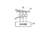
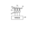
図7B乃至図7Dは、乱流生成部20の配置、構造の他の例を示す。図7Bおよび図7Cは、上述の第3ステップS3における分離部14の状態を示し、図7Dは、上述の第6ステップS6における分離部の状態を示している。第2例では、複数の乱流生成部20の各々は、移動することにより空気流路FA中の空気の流れの乱流化を抑制することが可能な部材22を含む。図7Cに示されるように、部材22は、駆動装置23に、機械的に接続されており、部材22は、駆動装置23(例えば、アクチュエータ)の作動により、移動する。なお、部材22が磁性体である場合には、駆動装置23は、部材22を磁力によって移動させる電磁石を含んでいてもよい。図7Bに記載の例では、部材22は、柱状部材であるが、当該部材22は、空気流路FAに向かって突出する突起を含んでいれば、どのような形状であってもよい。駆動装置23は、制御装置80からの制御信号を受信すると作動する。図7Cおよび図7Dに記載の例では、駆動装置23は、制御装置80から制御信号を受信すると作動して、部材22を空気流路FAから退避させる。すなわち、駆動装置23の作動により、部材22は、空気流路FAに向かって分離部14の壁面から突出した位置から、分離部14の壁面から突出しない退避位置に移動する。なお、図7Cおよび図7Dに記載の例では、1つの駆動装置23が対応する1つの部材22を駆動するように構成されているが、代替的に、1つの駆動装置23が複数の部材22を駆動するように構成されてもよい。
(Second example)
7B to 7D show another example of the arrangement and structure of the
図7Cは、駆動装置23の作動前の状態を示し、図7Dは、駆動装置23の作動後の状態を示す。図7Cに記載の状態では、部材22は、分離部14の壁面から空気流路FAに向かって突出している。このため、分離部14の壁面上の空気の流れは、部材22(乱流生成部20)によって乱流化される。なお、図7Cに記載の状態において、分離部14の壁面から、部材22の頂部までの高さは、例えば、0.5mm以上5.0mm以下である。他方、図7Dに記載の状態では、部材22は、分離部14の壁内に退避している。部材22の頂面が、分離部14の壁面と面一となるように、部材22は、分離部14の壁内に退避してもよい。
7C shows a state before the
制御装置80は、飛しょうマッハ数、飛しょう高度、および、飛しょう時間の少なくとも1つに基づいて、駆動装置23を作動させてもよい。飛しょうマッハ数、および/または、飛しょう高度は、センサ60によって取得されるデータに基づいて、制御装置80によって算出されてもよい。飛しょう時間は、制御装置80が備えるタイマによって計測されてもよい。制御装置80は、例えば、飛しょうマッハ数が上述の第1閾値TH1以上になると、駆動装置23を作動させてもよい。駆動装置23の作動により、部材22は、図7Cに示される突出位置から、図7Dに示される退避位置に移動する。
The
部材22が、空気流路FAに対して相対移動可能な移動可能部材を含む場合(換言すれば、分離部14の壁面に対して相対的に移動可能な移動可能部材を含む場合)、当該移動可能部材が配置される位置は、空気流路FAを流れる空気の流れ方向にみて、保炎器32が配置される位置とオーバーラップする位置であることが好ましい。すなわち、空気流路FAを流れる空気の流れ方向にみて、保炎器32が配置される位置とオーバーラップする領域(図7Bにおいて斜線で示される領域)に、少なくとも1つの移動可能部材(乱流生成部20)が配置されることが好ましい。当該位置関係を採用した場合、移動可能部材(乱流生成部20)によって、移動可能部材の近傍における高圧領域の形成が抑制される。その結果、保炎器32には、移動可能部材の近傍を介して、空気が円滑に供給される。
If the
なお、第2例において、乱流生成部20(部材22)が、消失することにより空気流路FA中の空気の流れの乱流化を抑制することが可能な材料を含まない場合、当該材料が、燃焼器(例えば、燃料噴射口30aあるいは保炎器32等)に再付着することによる悪影響を防止することができる。
In the second example, when the turbulent flow generation unit 20 (member 22) does not include a material capable of suppressing the turbulent flow of the air in the air flow path FA due to disappearance, the material concerned. However, it is possible to prevent an adverse effect due to redeposition on the combustor (for example, the
(第2例の変形例)
図7Eを参照して、第2例の変形例を示す。図7Eは、駆動装置23の作動前の状態を示す(すなわち、図7Eは、上述の第3ステップS3における分離部14の状態を示す)。図7Eに記載の例では、部材22が、空気流路FAに向かって分離部14の壁面から突出した位置ではなく、分離部14の壁内に退避した位置にある点で、上述の第2例とは異なる。第2例の変形例は、その他の点では、第2例と同様である。図7Eに記載の例では、部材22が分離部14の壁内に退避した位置にあることにより、分離部14と複数の部材22とによって複数の凹部24が形成されている。分離部14の壁面上の空気の流れは、当該複数の凹部24によって、乱流化される。
(Modification of the second example)
A modification of the second example will be described with reference to FIG. 7E. FIG. 7E shows the state before the
図7Dは、第2例の変形例において、駆動装置23の作動後の状態を示す。図7Eおよび図7Dに記載の例では、駆動装置23は、制御装置80から制御信号を受信すると作動して、部材22を空気流路FAにむけて移動させる。すなわち、駆動装置23の作動により、分離部14と複数の部材22とによって形成される複数の凹部24の深さが浅くなるか、あるいは、分離部14と複数の部材22とによって形成される複数の凹部24が消滅する。その結果、分離部14の壁面上の空気の流れの乱流化が抑制される。
FIG. 7D shows a state after the
(第3例)
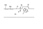
図7Fおよび図7Gは、乱流生成部25の配置、構造の他の例を示す。図7Fは、上述の第3ステップS3における分離部14の状態を示し、図7Gは、上述の第6ステップS6における分離部の状態を示している。第3例では、複数の乱流生成部25の各々は、飛しょう中の熱的影響(空力加熱等)または空力的影響(空力せん断力等)によって自動的に分離部14の壁面上から消失する部材25Bと、部材25Bの消失に伴い自動的に移動することにより空気流路FA中の空気の流れの乱流化を抑制することが可能な部材25A(移動可能部材)とを含む。部材25Aは、例えば、板状の部材である。図7Fに示される状態では、部材25Aの少なくとも一部が、分離部14の壁面から空気流路FAに向かって突出している。その結果、分離部14の壁面上の空気の流れは、複数の部材25A(複数の乱流生成部25)によって乱流化される。
(Third example)
7F and 7G show another example of the arrangement and structure of the turbulent
上述の第5ステップS5に対応して、部材25Bは、飛しょう中の熱的影響(空力加熱等)または空力的影響(空力せん断力等)によって自動的に分離部14の壁面上から消失する。部材25Aを突出状態に支持していた部材25Bが消失する結果、部材25Aは、分離部14の壁面に沿う位置に移動する。そして、部材25Aが、分離部14の壁面に沿う位置に移動すると、分離部14の壁面上の空気の流れの乱流化が抑制される。
Corresponding to the above-described fifth step S5, the
上述の第1例乃至第3例の少なくとも1つに示される構成を採用した場合、低速飛しょう時において、分離部14の壁面上の境界層が、壁面から剥離することが抑制される。その結果、燃焼圧が上流側に伝播することが抑制される。燃焼圧が上流側に伝播することが抑制されることにより、ジェットエンジンが低速度でも作動可能となる。すなわち、ジェットエンジンの作動可能な速度範囲が拡大する。また、上述の第1例乃至第3例の少なくとも1つに示される構成を備えたジェットエンジンを、ジェットエンジンの作動前にロケットモータを用いて加速する飛しょう体に適用した場合、必要なロケットモータの量が低減される。その結果、飛しょう体全体を小型化あるいは軽量化することができる。さらに、上述の第1例または第3例に示される構成を採用した場合、アクチュエータあるいは制御装置等を用いることなく、乱流生成部の状態を自動的に変化させることが可能となる。また、上述の第1例乃至第3例の少なくとも1つに示される構成を採用した場合、高速飛しょう時(例えば、巡航時)では、圧力損失を伴う空気流れの乱流化が抑制される。また、上述の第1例乃至第3例の少なくとも1つに示される構成を採用した場合、図2Aに記載の例のように分離部の長さを長くする必要がなくなる。その結果、ジェットエンジンの大型化(あるいは、飛しょう体の大型化)が抑制される。
When the configuration shown in at least one of the above-described first to third examples is adopted, the boundary layer on the wall surface of the separating
なお、複数の乱流生成部の具体的な構成として、上述の第1例乃至第3例のうちの少なくとも2つを組み合わせた構成を採用してもよい。代替的に、複数の乱流生成部の具体的な構成として、上述の第1例乃至第3例に示される構成以外の構成を採用してもよい。 In addition, as a specific configuration of the plurality of turbulent flow generation units, a configuration in which at least two of the first example to the third example described above are combined may be adopted. Alternatively, as a specific configuration of the plurality of turbulent flow generators, a configuration other than the configurations shown in the above-described first to third examples may be adopted.
本発明は上記各実施形態に限定されず、本発明の技術思想の範囲内において、各実施形態は適宜変形又は変更され得ることは明らかである。また、各実施形態又は変形例で用いられる種々の技術は、技術的矛盾が生じない限り、他の実施形態にも適用可能である。 The present invention is not limited to the above-described embodiments, and it is apparent that each embodiment can be appropriately modified or changed within the scope of the technical idea of the present invention. Further, the various techniques used in the respective embodiments or modifications can be applied to other embodiments as long as no technical contradiction occurs.
1 :飛しょう体
2 :ジェットエンジン
3 :ロケットモータ
10 :機体
11 :インレット
12 :燃焼器
13 :ノズル
14 :分離部
15 :インレットの後方端
16A :壁面
16B :壁面
20 :乱流生成部
21 :部材
22 :部材
23 :駆動装置
24 :凹部
25 :乱流生成部
25A :部材
25B :部材
30 :燃料噴射器
30a :燃料噴射口
32 :保炎器
40 :カウル
50 :空間
60 :センサ
80 :制御装置
102 :ジェットエンジン
102a :ジェットエンジン
110 :機体
110a :機体
111 :インレット
112 :燃焼器
112a :燃焼器
113 :ノズル
120 :燃料噴射器
121 :保炎器
121a :保炎器
140 :カウル
150 :空間
FA :空気流路
G :燃料
HP :高圧領域
MA :主流空気
1: Flying body 2: Jet engine 3: Rocket motor 10: Aircraft 11: Inlet 12: Combustor 13: Nozzle 14: Separation part 15:
Claims (11)
燃料を噴射する燃料噴射口を備え、前記インレットが取り込んだ前記空気を用いて前記燃料噴射口から噴射される燃料を燃焼する燃焼器と、
を具備し、
前記燃焼器は、前記インレットの前記空気が流れる方向における下流側の端部と前記燃料噴射口との間において、前記インレットが取り込んだ前記空気が流れる空気流路を規定する分離部を備え、
前記分離部には、前記空気流路における前記空気の流れを乱流化する複数の乱流生成部が配置され、
前記複数の乱流生成部の各々は、
前記分離部の壁面から前記空気流路に向かって突出し、前記壁面上の前記空気の流れの境界層を乱流化することが可能であり、かつ、
a)前記分離部の前記壁面から突出する位置から、前記壁面から突出しない位置へ移動するか、
b)前記分離部の前記壁面から突出する位置から、前記分離部の前記壁面に沿う位置に移動するか、または、
c)消失する
ことにより前記空気の流れの乱流化を抑制することが可能な部材
を含む
ジェットエンジン。 An inlet that takes in air,
A combustor having a fuel injection port for injecting fuel, and burning the fuel injected from the fuel injection port by using the air taken in by the inlet;
Equipped with,
The combustor, between the fuel injection port and the downstream end of the inlet in the direction in which the air flows, comprises a separating portion that defines an air flow path in which the air taken in by the inlet flows.
A plurality of turbulent flow generators that make the air flow in the air flow path turbulent are disposed in the separation unit,
Each of the plurality of turbulent flow generators,
It is possible to project from the wall surface of the separation portion toward the air flow path, to make the boundary layer of the air flow on the wall surface turbulent, and
a) moving from a position projecting from the wall surface of the separating portion to a position not projecting from the wall surface, or
b) moving from a position protruding from the wall surface of the separation portion to a position along the wall surface of the separation portion, or
c ) A jet engine including a member that can suppress the turbulence of the air flow by disappearing.
燃料を噴射する燃料噴射口を備え、前記空気を用いて前記燃料噴射口から噴射される燃料を燃焼する燃焼器と、
を具備し、
前記燃焼器は、前記インレットの後端と前記燃料噴射口との間において、前記空気が流れる空気流路を規定する分離部を備え、
前記分離部には、前記空気の流れを乱流化する複数の乱流生成部が配置され、
前記複数の乱流生成部の各々は、移動するか消失することにより前記空気の流れの乱流化を抑制することが可能な部材を含み、
前記部材は、前記空気流路に向かって突出する突起を含む
ジェットエンジン。 An inlet that takes in air,
A combustor having a fuel injection port for injecting fuel, and burning the fuel injected from the fuel injection port using the air;
Equipped with,
The combustor, between the rear end of the inlet and the fuel injection port, includes a separating portion that defines an air flow path through which the air flows,
A plurality of turbulent flow generators that make the air flow turbulent are disposed in the separation unit,
Each of the plurality of turbulent flow generation sections includes a member capable of suppressing turbulence of the air flow by moving or disappearing,
A jet engine in which the member includes a protrusion protruding toward the air flow path.
燃料を噴射する燃料噴射口を備え、前記空気を用いて前記燃料噴射口から噴射される燃料を燃焼する燃焼器と、
を具備し、
前記燃焼器は、前記インレットの後端と前記燃料噴射口との間において、前記空気が流れる空気流路を規定する分離部を備え、
前記分離部には、前記空気の流れを乱流化する複数の乱流生成部が配置され、
前記複数の乱流生成部の各々は、移動するか消失することにより前記空気の流れの乱流化を抑制することが可能な部材を含み、
前記部材は、飛しょう中の熱的影響又は空力的影響により前記分離部の壁面上から消失する材料を含む
ジェットエンジン。 An inlet that takes in air,
A combustor having a fuel injection port for injecting fuel, and burning the fuel injected from the fuel injection port using the air;
Equipped with,
The combustor, between the rear end of the inlet and the fuel injection port, includes a separating portion that defines an air flow path through which the air flows,
A plurality of turbulent flow generators that make the air flow turbulent are disposed in the separation unit,
Each of the plurality of turbulent flow generation sections includes a member capable of suppressing turbulence of the air flow by moving or disappearing,
The member, jet engine comprising a material that disappears from the wall surface of the separating portion by thermal influence or aerodynamic impact during flight.
燃料を噴射する燃料噴射口を備え、前記空気を用いて前記燃料噴射口から噴射される燃料を燃焼する燃焼器と、
を具備し、
前記燃焼器は、前記インレットの後端と前記燃料噴射口との間において、前記空気が流れる空気流路を規定する分離部を備え、
前記分離部には、前記空気の流れを乱流化する複数の乱流生成部が配置され、
前記複数の乱流生成部の各々は、移動するか消失することにより前記空気の流れの乱流化を抑制することが可能な部材を含み、
前記部材は、飛しょう中の熱的影響又は空力的影響により前記分離部の壁面上から消失する材料を含み、
前記部材が配置される前記分離部の壁面上の位置は、前記空気流路を流れる前記空気の流れの方向にみて、前記燃料噴射口が配置される位置とオーバーラップしない
ジェットエンジン。 An inlet that takes in air,
A combustor having a fuel injection port for injecting fuel, and burning the fuel injected from the fuel injection port using the air;
Equipped with,
The combustor, between the rear end of the inlet and the fuel injection port, includes a separating portion that defines an air flow path through which the air flows,
A plurality of turbulent flow generators that make the air flow turbulent are disposed in the separation unit,
Each of the plurality of turbulent flow generation sections includes a member capable of suppressing turbulence of the air flow by moving or disappearing,
It said member includes a material which disappears from the wall surface of the separating portion by thermal influence or aerodynamic impact during flight,
A position on the wall surface of the separation portion where the member is disposed does not overlap with a position where the fuel injection port is disposed, as viewed in the direction of the air flow through the air flow path.
燃料を噴射する燃料噴射口を備え、前記空気を用いて前記燃料噴射口から噴射される燃料を燃焼する燃焼器と、
を具備し、
前記燃焼器は、前記インレットの後端と前記燃料噴射口との間において、前記空気が流れる空気流路を規定する分離部を備え、
前記分離部には、前記空気の流れを乱流化する複数の乱流生成部が配置され、
前記複数の乱流生成部の各々は、移動するか消失することにより前記空気の流れの乱流化を抑制することが可能な部材を含み、
前記部材は、飛しょう中の熱的影響又は空力的影響により前記分離部の壁面上から消失する材料を含み、
前記部材が配置される前記分離部の壁面上の位置は、前記空気流路を流れる前記空気の流れの方向にみて、前記燃料噴射口が配置される位置とオーバーラップせず、
前記燃焼器は、前記燃料噴射口が配置された第1壁面と、前記複数の乱流生成部が配置された第2壁面と
を備え、
前記第2壁面は、前記第1壁面とは異なる壁面である
ジェットエンジン。 An inlet that takes in air,
A combustor having a fuel injection port for injecting fuel, and burning the fuel injected from the fuel injection port using the air;
Equipped with,
The combustor, between the rear end of the inlet and the fuel injection port, includes a separating portion that defines an air flow path through which the air flows,
A plurality of turbulent flow generators that make the air flow turbulent are disposed in the separation unit,
Each of the plurality of turbulent flow generation sections includes a member capable of suppressing turbulence of the air flow by moving or disappearing,
It said member includes a material which disappears from the wall surface of the separating portion by thermal influence or aerodynamic impact during flight,
The position on the wall surface of the separation portion where the member is disposed does not overlap with the position where the fuel injection port is disposed, as viewed in the direction of the flow of the air flowing through the air flow path,
The combustor includes a first wall surface on which the fuel injection port is arranged and a second wall surface on which the plurality of turbulent flow generators are arranged,
A jet engine in which the second wall surface is different from the first wall surface.
請求項1または2に記載のジェットエンジン。 The jet engine according to claim 1, wherein the member is a movable member that is movable with respect to the air flow path.
燃料を噴射する燃料噴射口を備え、前記空気を用いて前記燃料噴射口から噴射される燃料を燃焼する燃焼器と、
を具備し、
前記燃焼器は、前記インレットの後端と前記燃料噴射口との間において、前記空気が流れる空気流路を規定する分離部を備え、
前記分離部には、前記空気の流れを乱流化する複数の乱流生成部が配置され、
前記複数の乱流生成部の各々は、移動するか消失することにより前記空気の流れの乱流化を抑制することが可能な部材を含み、
前記部材は、前記空気流路に対して移動可能な移動可能部材であり、
前記移動可能部材は、飛しょう中の熱的影響又は空力的影響により自動的に移動するように構成されている
ジェットエンジン。 An inlet that takes in air,
A combustor having a fuel injection port for injecting fuel, and burning the fuel injected from the fuel injection port using the air;
Equipped with,
The combustor, between the rear end of the inlet and the fuel injection port, includes a separating portion that defines an air flow path through which the air flows,
A plurality of turbulent flow generators that make the air flow turbulent are disposed in the separation unit,
Each of the plurality of turbulent flow generation sections includes a member capable of suppressing turbulence of the air flow by moving or disappearing,
The member is a movable member that is movable with respect to the air flow path,
A jet engine in which the movable member is configured to automatically move due to thermal or aerodynamic effects during flight.
燃料を噴射する燃料噴射口を備え、前記空気を用いて前記燃料噴射口から噴射される燃料を燃焼する燃焼器と、
を具備し、
前記燃焼器は、前記インレットの後端と前記燃料噴射口との間において、前記空気が流れる空気流路を規定する分離部を備え、
前記分離部には、前記空気の流れを乱流化する複数の乱流生成部が配置され、
前記複数の乱流生成部の各々は、移動するか消失することにより前記空気の流れの乱流化を抑制することが可能な部材を含み、
前記部材は、前記空気流路に対して移動可能な移動可能部材であり、
前記移動可能部材を移動させる駆動装置と、
前記駆動装置を制御する制御装置と
を更に備え、
前記制御装置は、飛しょうマッハ数、飛しょう高度、および、飛しょう時間の少なくとも1つに基づいて、前記駆動装置を作動させ、
前記駆動装置は、作動することにより、前記移動可能部材の前記空気流路に対する進出状態あるいは退避状態を変化させる
ジェットエンジン。 An inlet that takes in air,
A combustor having a fuel injection port for injecting fuel, and burning the fuel injected from the fuel injection port using the air;
Equipped with,
The combustor, between the rear end of the inlet and the fuel injection port, includes a separating portion that defines an air flow path through which the air flows,
A plurality of turbulent flow generators that make the air flow turbulent are disposed in the separation unit,
Each of the plurality of turbulent flow generation sections includes a member capable of suppressing turbulence of the air flow by moving or disappearing,
The member is a movable member that is movable with respect to the air flow path,
A drive device for moving the movable member,
Further comprising a control device for controlling the drive device,
The control device operates the drive device based on at least one of flight Mach number, flight altitude, and flight time;
A jet engine in which the drive device operates to change the advance state or the retreat state of the movable member with respect to the air flow path.
燃料を噴射する燃料噴射口を備え、前記空気を用いて前記燃料噴射口から噴射される燃料を燃焼する燃焼器と、
を具備し、
前記燃焼器は、前記インレットの後端と前記燃料噴射口との間において、前記空気が流れる空気流路を規定する分離部を備え、
前記分離部には、前記空気の流れを乱流化する複数の乱流生成部が配置され、
前記複数の乱流生成部の各々は、移動するか消失することにより前記空気の流れの乱流化を抑制することが可能な部材を含み、
前記部材は、前記空気流路に対して移動可能な移動可能部材であり、
前記燃焼器は、保炎器を備え、
前記移動可能部材が配置される位置は、前記空気流路を流れる前記空気の流れの方向にみて、前記保炎器が配置される位置とオーバーラップする
ジェットエンジン。 An inlet that takes in air,
A combustor having a fuel injection port for injecting fuel, and burning the fuel injected from the fuel injection port using the air;
Equipped with,
The combustor, between the rear end of the inlet and the fuel injection port, includes a separating portion that defines an air flow path through which the air flows,
A plurality of turbulent flow generators that make the air flow turbulent are disposed in the separation unit,
Each of the plurality of turbulent flow generation sections includes a member capable of suppressing turbulence of the air flow by moving or disappearing,
The member is a movable member that is movable with respect to the air flow path,
The combustor includes a flame stabilizer,
A jet engine in which a position where the movable member is arranged overlaps with a position where the flame stabilizer is arranged, as viewed in the direction of the flow of the air flowing through the air flow path.
ここで、前記ジェットエンジンは、
空気を取り込むインレットと、
燃料を噴射する燃料噴射口を備え、前記空気を用いて前記燃料噴射口から噴射される燃料を燃焼する燃焼器と
を具備し、
前記燃焼器は、前記インレットの後端と前記燃料噴射口との間において、前記空気が流れる空気流路を規定する分離部を備え、
前記分離部には、前記空気の流れを乱流化する複数の乱流生成部が配置され、
前記ジェットエンジンの動作方法は、
前記複数の乱流生成部により、前記分離部の壁面上の前記空気の流れを乱流化しつつ、前記空気を用いて前記燃料噴射口から噴射される燃料を燃焼する工程と、
前記複数の乱流生成部の各々を構成する部材の少なくとも一部を消失または移動させる工程と、
前記分離部の壁面上の前記空気の流れの乱流化を抑制しつつ、前記空気を用いて前記燃料噴射口から噴射される燃料を燃焼する工程と
を具備する
ジェットエンジンの動作方法。
A method of operating a jet engine,
Here, the jet engine is
An inlet that takes in air,
A fuel injector for injecting fuel, and a combustor for burning the fuel injected from the fuel injector using the air,
The combustor, between the rear end of the inlet and the fuel injection port, includes a separating portion that defines an air flow path through which the air flows,
A plurality of turbulent flow generators that make the air flow turbulent are disposed in the separation unit,
The operation method of the jet engine is
Combusting the fuel injected from the fuel injection port by using the air while making the flow of the air on the wall surface of the separation unit turbulent by the plurality of turbulent flow generating units,
Disappearing or moving at least a part of the members constituting each of the plurality of turbulent flow generation sections,
A method of operating a jet engine, comprising: using the air to burn fuel injected from the fuel injection port while suppressing turbulence of the flow of the air on the wall surface of the separation unit.
Priority Applications (4)
| Application Number | Priority Date | Filing Date | Title |
|---|---|---|---|
| JP2016052186A JP6719933B2 (en) | 2016-03-16 | 2016-03-16 | Jet engine, flying body, and how to operate jet engine |
| EP16894475.9A EP3396146B1 (en) | 2016-03-16 | 2016-06-22 | Jet engine, flying object, and operation method for jet engine |
| US16/071,980 US11248562B2 (en) | 2016-03-16 | 2016-06-22 | Jet engine, flying object, and operation method of jet engine |
| PCT/JP2016/068484 WO2017158857A1 (en) | 2016-03-16 | 2016-06-22 | Jet engine, flying object, and operation method for jet engine |
Applications Claiming Priority (1)
| Application Number | Priority Date | Filing Date | Title |
|---|---|---|---|
| JP2016052186A JP6719933B2 (en) | 2016-03-16 | 2016-03-16 | Jet engine, flying body, and how to operate jet engine |
Publications (2)
| Publication Number | Publication Date |
|---|---|
| JP2017166410A JP2017166410A (en) | 2017-09-21 |
| JP6719933B2 true JP6719933B2 (en) | 2020-07-08 |
Family
ID=59852055
Family Applications (1)
| Application Number | Title | Priority Date | Filing Date |
|---|---|---|---|
| JP2016052186A Active JP6719933B2 (en) | 2016-03-16 | 2016-03-16 | Jet engine, flying body, and how to operate jet engine |
Country Status (4)
| Country | Link |
|---|---|
| US (1) | US11248562B2 (en) |
| EP (1) | EP3396146B1 (en) |
| JP (1) | JP6719933B2 (en) |
| WO (1) | WO2017158857A1 (en) |
Families Citing this family (8)
| Publication number | Priority date | Publication date | Assignee | Title |
|---|---|---|---|---|
| US11204000B2 (en) | 2017-03-24 | 2021-12-21 | Raytheon Company | Flight vehicle engine with finned inlet |
| US11261785B2 (en) | 2017-06-06 | 2022-03-01 | Raytheon Company | Flight vehicle air breathing engine with isolator having bulged section |
| US10590848B2 (en) * | 2017-06-06 | 2020-03-17 | Raytheon Company | Flight vehicle air breathing propulsion system with isolator having obstruction |
| US11002223B2 (en) | 2017-12-06 | 2021-05-11 | Raytheon Company | Flight vehicle with air inlet isolator having wedge on inner mold line |
| JP7001489B2 (en) | 2018-02-09 | 2022-01-19 | 三菱重工業株式会社 | Scramjet engine and projectile |
| US11053018B2 (en) | 2018-06-27 | 2021-07-06 | Raytheon Company | Flight vehicle engine inlet with internal diverter, and method of configuring |
| US11359578B2 (en) * | 2018-08-06 | 2022-06-14 | General Electric Company | Ramjet engine with rotating detonation combustion system and method for operation |
| CN113123898B (en) * | 2021-04-19 | 2022-06-07 | 中国人民解放军国防科技大学 | Supersonic flow mixing device based on jet flow disturbance at rear edge of partition plate |
Family Cites Families (20)
| Publication number | Priority date | Publication date | Assignee | Title |
|---|---|---|---|---|
| US2908136A (en) | 1956-12-14 | 1959-10-13 | United Aircraft Corp | Low drag flameholder capable of flutter during operation |
| US2936585A (en) | 1958-01-15 | 1960-05-17 | Gen Electric | Variable blockage flame stabilizer |
| US4291533A (en) * | 1965-12-30 | 1981-09-29 | The United States Of America As Represented By The Secretary Of The Navy | Supersonic ramjet missile |
| JPH02112656A (en) | 1988-10-20 | 1990-04-25 | Mitsubishi Heavy Ind Ltd | Combustion method in jet engine combustor |
| EP0381399B1 (en) * | 1989-02-02 | 1994-07-13 | Hitachi, Ltd. | Vane controller |
| US6484971B2 (en) | 2000-07-24 | 2002-11-26 | Thombi Layukallo | Control of flow separation and related phenomena on aerodynamic surfaces |
| JP2002079996A (en) | 2000-07-24 | 2002-03-19 | Layukallo Thombi | Method and device for restraining separation of flow on aerodynamic surface and phenomenon relating to it |
| US6427948B1 (en) * | 2000-10-30 | 2002-08-06 | Michael Campbell | Controllable vortex generator |
| US6837465B2 (en) * | 2003-01-03 | 2005-01-04 | Orbital Research Inc | Flow control device and method of controlling flow |
| WO2007005687A1 (en) * | 2005-06-30 | 2007-01-11 | Bell Helicopter Textron Inc. | Retractable vortex generator |
| US7762077B2 (en) * | 2006-12-05 | 2010-07-27 | Pratt & Whitney Rocketdyne, Inc. | Single-stage hypersonic vehicle featuring advanced swirl combustion |
| EP1936468A1 (en) * | 2006-12-22 | 2008-06-25 | Siemens Aktiengesellschaft | Bi-metallic elements for adjusting a cooling channel |
| US7954754B2 (en) * | 2008-06-02 | 2011-06-07 | The United States Of America As Represented By The Secretary Of The Army | Mechanical acoustic noise generator system for scramjet engine |
| US20170137116A1 (en) * | 2009-07-10 | 2017-05-18 | Peter Ireland | Efficiency improvements for flow control body and system shocks |
| JP5449087B2 (en) | 2010-08-12 | 2014-03-19 | 三菱重工業株式会社 | Wing |
| JP6037818B2 (en) | 2012-12-21 | 2016-12-07 | 三菱重工業株式会社 | Jet engine |
| JP6310292B2 (en) | 2014-03-26 | 2018-04-11 | 三菱重工業株式会社 | Combustor, jet engine, flying object, and operation method of jet engine |
| JP6268529B2 (en) | 2014-03-28 | 2018-01-31 | 三菱重工業株式会社 | Jet engine, flying object and operation method of jet engine |
| JP6204250B2 (en) | 2014-03-31 | 2017-09-27 | 三菱重工業株式会社 | Jet engine, flying object and operation method of jet engine |
| US9789956B2 (en) * | 2014-09-19 | 2017-10-17 | The Boeing Company | Vortex generators responsive to ambient conditions |
-
2016
- 2016-03-16 JP JP2016052186A patent/JP6719933B2/en active Active
- 2016-06-22 US US16/071,980 patent/US11248562B2/en active Active
- 2016-06-22 EP EP16894475.9A patent/EP3396146B1/en active Active
- 2016-06-22 WO PCT/JP2016/068484 patent/WO2017158857A1/en active Application Filing
Also Published As
| Publication number | Publication date |
|---|---|
| US20190032602A1 (en) | 2019-01-31 |
| JP2017166410A (en) | 2017-09-21 |
| EP3396146A1 (en) | 2018-10-31 |
| US11248562B2 (en) | 2022-02-15 |
| EP3396146B1 (en) | 2020-05-27 |
| EP3396146A4 (en) | 2018-12-19 |
| WO2017158857A1 (en) | 2017-09-21 |
Similar Documents
| Publication | Publication Date | Title |
|---|---|---|
| JP6719933B2 (en) | Jet engine, flying body, and how to operate jet engine | |
| JP6268529B2 (en) | Jet engine, flying object and operation method of jet engine | |
| JP5791323B2 (en) | Scramjet engine | |
| EP3098515B1 (en) | Jet engine, flying body, and method for operating a jet engine | |
| JP2020522427A (en) | Flight vehicle air engine with isolator having bulge | |
| JP6310292B2 (en) | Combustor, jet engine, flying object, and operation method of jet engine | |
| WO2015151621A1 (en) | Jet engine, flying vehicle, and method for operating jet engine | |
| JP6310293B2 (en) | Combustor, jet engine, flying object, and operation method of jet engine | |
| WO2017158856A1 (en) | Jet engine and flying object | |
| JP6204250B2 (en) | Jet engine, flying object and operation method of jet engine | |
| WO2019155654A1 (en) | Scramjet engine and flying object | |
| JP6788522B2 (en) | Scramjet engine | |
| JP6085472B2 (en) | Scramjet engine and combustion control method |
Legal Events
| Date | Code | Title | Description |
|---|---|---|---|
| RD04 | Notification of resignation of power of attorney |
Free format text: JAPANESE INTERMEDIATE CODE: A7424 Effective date: 20160825 |
|
| A621 | Written request for application examination |
Free format text: JAPANESE INTERMEDIATE CODE: A621 Effective date: 20181024 |
|
| RD03 | Notification of appointment of power of attorney |
Free format text: JAPANESE INTERMEDIATE CODE: A7423 Effective date: 20190226 |
|
| A131 | Notification of reasons for refusal |
Free format text: JAPANESE INTERMEDIATE CODE: A131 Effective date: 20190807 |
|
| A521 | Request for written amendment filed |
Free format text: JAPANESE INTERMEDIATE CODE: A523 Effective date: 20191003 |
|
| A131 | Notification of reasons for refusal |
Free format text: JAPANESE INTERMEDIATE CODE: A131 Effective date: 20191120 |
|
| RD04 | Notification of resignation of power of attorney |
Free format text: JAPANESE INTERMEDIATE CODE: A7424 Effective date: 20191125 |
|
| A521 | Request for written amendment filed |
Free format text: JAPANESE INTERMEDIATE CODE: A523 Effective date: 20200117 |
|
| TRDD | Decision of grant or rejection written | ||
| A01 | Written decision to grant a patent or to grant a registration (utility model) |
Free format text: JAPANESE INTERMEDIATE CODE: A01 Effective date: 20200610 |
|
| A61 | First payment of annual fees (during grant procedure) |
Free format text: JAPANESE INTERMEDIATE CODE: A61 Effective date: 20200617 |
|
| R150 | Certificate of patent or registration of utility model |
Ref document number: 6719933 Country of ref document: JP Free format text: JAPANESE INTERMEDIATE CODE: R150 |