JP6999068B2 - Seal ring - Google Patents
Seal ring Download PDFInfo
- Publication number
- JP6999068B2 JP6999068B2 JP2021532696A JP2021532696A JP6999068B2 JP 6999068 B2 JP6999068 B2 JP 6999068B2 JP 2021532696 A JP2021532696 A JP 2021532696A JP 2021532696 A JP2021532696 A JP 2021532696A JP 6999068 B2 JP6999068 B2 JP 6999068B2
- Authority
- JP
- Japan
- Prior art keywords
- seal ring
- peripheral surface
- joint
- groove
- hole
- Prior art date
- Legal status (The legal status is an assumption and is not a legal conclusion. Google has not performed a legal analysis and makes no representation as to the accuracy of the status listed.)
- Active
Links
Images


Classifications
-
- F—MECHANICAL ENGINEERING; LIGHTING; HEATING; WEAPONS; BLASTING
- F16—ENGINEERING ELEMENTS AND UNITS; GENERAL MEASURES FOR PRODUCING AND MAINTAINING EFFECTIVE FUNCTIONING OF MACHINES OR INSTALLATIONS; THERMAL INSULATION IN GENERAL
- F16J—PISTONS; CYLINDERS; SEALINGS
- F16J15/00—Sealings
- F16J15/16—Sealings between relatively-moving surfaces
- F16J15/18—Sealings between relatively-moving surfaces with stuffing-boxes for elastic or plastic packings
- F16J15/181—Sealings between relatively-moving surfaces with stuffing-boxes for elastic or plastic packings for plastic packings
-
- F—MECHANICAL ENGINEERING; LIGHTING; HEATING; WEAPONS; BLASTING
- F16—ENGINEERING ELEMENTS AND UNITS; GENERAL MEASURES FOR PRODUCING AND MAINTAINING EFFECTIVE FUNCTIONING OF MACHINES OR INSTALLATIONS; THERMAL INSULATION IN GENERAL
- F16J—PISTONS; CYLINDERS; SEALINGS
- F16J15/00—Sealings
- F16J15/16—Sealings between relatively-moving surfaces
- F16J15/18—Sealings between relatively-moving surfaces with stuffing-boxes for elastic or plastic packings
-
- F—MECHANICAL ENGINEERING; LIGHTING; HEATING; WEAPONS; BLASTING
- F16—ENGINEERING ELEMENTS AND UNITS; GENERAL MEASURES FOR PRODUCING AND MAINTAINING EFFECTIVE FUNCTIONING OF MACHINES OR INSTALLATIONS; THERMAL INSULATION IN GENERAL
- F16J—PISTONS; CYLINDERS; SEALINGS
- F16J15/00—Sealings
- F16J15/16—Sealings between relatively-moving surfaces
- F16J15/32—Sealings between relatively-moving surfaces with elastic sealings, e.g. O-rings
- F16J15/3268—Mounting of sealing rings
- F16J15/3272—Mounting of sealing rings the rings having a break or opening, e.g. to enable mounting on a shaft otherwise than from a shaft end
-
- F—MECHANICAL ENGINEERING; LIGHTING; HEATING; WEAPONS; BLASTING
- F16—ENGINEERING ELEMENTS AND UNITS; GENERAL MEASURES FOR PRODUCING AND MAINTAINING EFFECTIVE FUNCTIONING OF MACHINES OR INSTALLATIONS; THERMAL INSULATION IN GENERAL
- F16J—PISTONS; CYLINDERS; SEALINGS
- F16J15/00—Sealings
- F16J15/16—Sealings between relatively-moving surfaces
- F16J15/34—Sealings between relatively-moving surfaces with slip-ring pressed against a more or less radial face on one member
- F16J15/3436—Pressing means
- F16J15/3448—Pressing means the pressing force resulting from fluid pressure
-
- F—MECHANICAL ENGINEERING; LIGHTING; HEATING; WEAPONS; BLASTING
- F16—ENGINEERING ELEMENTS AND UNITS; GENERAL MEASURES FOR PRODUCING AND MAINTAINING EFFECTIVE FUNCTIONING OF MACHINES OR INSTALLATIONS; THERMAL INSULATION IN GENERAL
- F16J—PISTONS; CYLINDERS; SEALINGS
- F16J15/00—Sealings
- F16J15/44—Free-space packings
- F16J15/441—Free-space packings with floating ring
-
- F—MECHANICAL ENGINEERING; LIGHTING; HEATING; WEAPONS; BLASTING
- F16—ENGINEERING ELEMENTS AND UNITS; GENERAL MEASURES FOR PRODUCING AND MAINTAINING EFFECTIVE FUNCTIONING OF MACHINES OR INSTALLATIONS; THERMAL INSULATION IN GENERAL
- F16J—PISTONS; CYLINDERS; SEALINGS
- F16J15/00—Sealings
- F16J15/54—Other sealings for rotating shafts
-
- F—MECHANICAL ENGINEERING; LIGHTING; HEATING; WEAPONS; BLASTING
- F16—ENGINEERING ELEMENTS AND UNITS; GENERAL MEASURES FOR PRODUCING AND MAINTAINING EFFECTIVE FUNCTIONING OF MACHINES OR INSTALLATIONS; THERMAL INSULATION IN GENERAL
- F16J—PISTONS; CYLINDERS; SEALINGS
- F16J15/00—Sealings
- F16J15/02—Sealings between relatively-stationary surfaces
- F16J15/06—Sealings between relatively-stationary surfaces with solid packing compressed between sealing surfaces
- F16J15/10—Sealings between relatively-stationary surfaces with solid packing compressed between sealing surfaces with non-metallic packing
- F16J15/104—Sealings between relatively-stationary surfaces with solid packing compressed between sealing surfaces with non-metallic packing characterised by structure
-
- F—MECHANICAL ENGINEERING; LIGHTING; HEATING; WEAPONS; BLASTING
- F16—ENGINEERING ELEMENTS AND UNITS; GENERAL MEASURES FOR PRODUCING AND MAINTAINING EFFECTIVE FUNCTIONING OF MACHINES OR INSTALLATIONS; THERMAL INSULATION IN GENERAL
- F16J—PISTONS; CYLINDERS; SEALINGS
- F16J15/00—Sealings
- F16J15/16—Sealings between relatively-moving surfaces
- F16J15/164—Sealings between relatively-moving surfaces the sealing action depending on movements; pressure difference, temperature or presence of leaking fluid
Landscapes
- Engineering & Computer Science (AREA)
- General Engineering & Computer Science (AREA)
- Mechanical Engineering (AREA)
- Physics & Mathematics (AREA)
- Fluid Mechanics (AREA)
- Sealing Devices (AREA)
Description
本発明は、相対的に回転する外側部材と内側部材の間に配置される樹脂製の円環状のシールリングに関する。 The present invention relates to an annular seal ring made of resin arranged between a relatively rotating outer member and an inner member.
円環状のシールリングは、回転部材を有する様々な機械の環状の隙間を封止するために使用されている。例えば、自動車の動力伝達軸とハウジングの間に、ハウジング内の潤滑油を密封するシールリングが配置されている。 An annular seal ring is used to seal the annular gaps of various machines with rotating members. For example, a seal ring for sealing the lubricating oil in the housing is arranged between the power transmission shaft of the automobile and the housing.
一般にシールリングは、長尺の円弧状の棒から、棒の両端部を接合することにより、円形をなすよう形成されている。 Generally, the seal ring is formed from a long arc-shaped rod to form a circle by joining both ends of the rod.
シールリングの形状に関して、様々な提案がされている(特許文献1および2)。
Various proposals have been made regarding the shape of the seal ring (
シールリングの封止性能を高める観点から、シールリングの外周面または内周面が真円柱形に合致し、封止される部材とシールリングの間の隙間がないことが理想的である。 From the viewpoint of enhancing the sealing performance of the seal ring, it is ideal that the outer peripheral surface or the inner peripheral surface of the seal ring conforms to a true cylindrical shape and there is no gap between the member to be sealed and the seal ring.
そこで、本発明は、シールリングを定位置に配備した場合、封止される部材とシールリングの間の隙間が極めて小さいシールリングを提供する。 Therefore, the present invention provides a seal ring in which the gap between the member to be sealed and the seal ring is extremely small when the seal ring is deployed at a fixed position.
本発明のある態様に係るシールリングは、相対的に回転する外側部材と内側部材の間に配置される樹脂製の円環状のシールリングである。シールリングは、長尺の円弧状の棒から前記棒の両端部を接合することにより、円形をなすよう形成されており、前記両端部から形成された接合部を有する。前記シールリングの径方向の厚さは、前記接合部から離れた2つの地点から前記接合部に向けて、徐々に減少しており、前記地点は、前記円形の中心軸を中心として、前記接合部から60度以上、150度以下の角度、離れている。 The seal ring according to an aspect of the present invention is a resin annular seal ring arranged between a relatively rotating outer member and an inner member. The seal ring is formed to form a circle by joining both ends of the rod from a long arc-shaped rod, and has a joint formed from the both ends. The radial thickness of the seal ring gradually decreases from two points away from the joint toward the joint, where the joint is centered on the circular central axis. It is separated from the part by an angle of 60 degrees or more and 150 degrees or less.
この態様においては、シールリングを外側部材の円柱形の内周面に接触するよう配備した場合、シールリングの外周面が真円柱形に極めて近似し、外側部材の内周面とシールリングの外周面の間の隙間が極めて小さい。シールリングを内側部材の円柱形の外周面に接触するよう配備した場合、シールリングの内周面が真円柱形に極めて近似し、内側部材の外周面とシールリングの内周面の間の隙間が極めて小さい。したがって、いずれの場合もシールリングの封止性能が著しく高い。 In this embodiment, when the seal ring is arranged so as to be in contact with the inner peripheral surface of the cylindrical shape of the outer member, the outer peripheral surface of the seal ring closely resembles a true cylindrical shape, and the inner peripheral surface of the outer member and the outer peripheral surface of the seal ring are very close to each other. The gap between the surfaces is extremely small. When the seal ring is deployed so as to contact the outer peripheral surface of the cylindrical shape of the inner member, the inner peripheral surface of the seal ring closely resembles a true cylindrical shape, and the gap between the outer peripheral surface of the inner member and the inner peripheral surface of the seal ring. Is extremely small. Therefore, in either case, the sealing performance of the seal ring is remarkably high.
以下、添付の図面を参照しながら本発明に係る様々な実施の形態を説明する。図面の縮尺は必ずしも正確ではなく、一部の特徴は誇張または省略されることもある。 Hereinafter, various embodiments according to the present invention will be described with reference to the accompanying drawings. Drawing scales are not always accurate and some features may be exaggerated or omitted.
以下に説明する本発明の各実施形態に係るシールリングを有する密封構造は、自動車の動力伝達軸とハウジングの環状の隙間を封止するために使用される。但し、以下の説明は、例示であって、本発明に係るシールリングを有する密封構造は、各種の油圧機器、水圧機器、空気圧機器において、潤滑油および冷却水などの液体を密封するために使用されうる。これらの機器は、例えば、エンジン、モーター、発電機、ポンプ、コンプレッサー、自動車のパワーステアリング、減速機、変速機、冷却機を含む。 The sealing structure with the sealing ring according to each embodiment of the present invention described below is used to seal the annular gap between the power transmission shaft of the vehicle and the housing. However, the following description is an example, and the sealing structure having a sealing ring according to the present invention is used for sealing liquids such as lubricating oil and cooling water in various hydraulic equipment, hydraulic equipment, and pneumatic equipment. Can be done. These devices include, for example, engines, motors, generators, pumps, compressors, automotive power steering, reducers, transmissions, coolers.
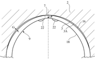
第1の実施形態
図1に示すように、本発明の第1の実施形態に係る密封構造1は、ハウジング(外側部材)2、軸(内側部材)4、シールリング6を備える。ハウジング2は、固定された部材であり、円柱形の内周面3Aを有する孔3と、被密封潤滑油が内部に配置された潤滑油空間(液体空間)Aを有する。潤滑油空間Aは孔3に連通する。潤滑油空間Aには、軸4が挿入されている。軸4は、中心軸Axの周囲を回転する回転軸であり、自動車の動力伝達軸である。First Embodiment As shown in FIG. 1, the
軸4のうち、孔3に挿入された部分の外周面には、周溝8が形成されている。周溝8には、樹脂製の円環状のシールリング6が配置されて、この結果、シールリング6は孔3内に挿入されている。シールリング6は、軸4とハウジング2の間の隙間を封止して、ハウジング2の内部の潤滑油空間Aから外部空間(大気空間)Bへ潤滑油が漏出するのを防止または低減させる。
A
シールリング6の径方向外側の部分は、周溝8から径方向外側に突出しており、シールリング6の外周面16は、孔3の内周面3Aに接触する。シールリング6は、ハウジング2の孔3に固定される。ここで、「固定される」とは、シールリング6の位置がハウジング2に対して静止していることを意味し、シールリング6がハウジング2に取り外し不能に結合されているか否かを限定する意図ではない。この実施形態では、シールリング6は孔3の内周面3Aに締まり嵌めされる。さらに、後述するように、シールリング6はシールリング6の内側の潤滑油から圧力を受けることにより、ハウジング2に固定されている。
The radial outer portion of the
また、シールリング6は、軸4に対して摺動可能に軸4の周溝8内に配置されている。シールリング6は、潤滑油空間Aと外部空間Bを隔離し、潤滑油をハウジング2の潤滑油空間A内に閉じ込める。この密封構造1において、ハウジング2とシールリング6が固定されているのに対して、軸4はハウジング2に対して回転する。
Further, the
この実施形態では、シールリング6は、矩形の断面を有する。
In this embodiment, the
シールリング6は、ポリエーテルエーテルケトン(PEEK)、ポリフェニレンサルファイド(PPS)、ポリテトラフルオロエチレン(PTFE)などの樹脂材料から形成されている。シールリング6は、これらの材料をベースポリマーとして、摺動特性や強度を向上させるための充填剤を含む樹脂材料から形成されてもよい。
The
図2に示すように、シールリング6は、2つの端部6A,6Bを有する長尺の湾曲した円弧状の棒から構成されている。具体的には、シールリング6は、長尺の円弧状の棒から、棒の両端部6A,6Bを接合することにより、円形をなすよう形成されている。したがって、シールリング6は、両端部6A,6Bから形成された接合部7を有する。このように、シールリング6は、無端リングではなく、円弧状の棒から形成されているので、シールリング6を軸4の外周面に形成された周溝8に嵌め込むように、シールリング6を軸4の周囲に配置するのが容易である。
As shown in FIG. 2, the
図2に示す端部6A,6Bの形状は、公知であって、特殊ステップカットと呼ばれる。特殊ステップカットは、シールリング6の周方向への拡張(ひいては径方向への拡張)を許容し、なおかつ高い封止性能を有するので、優れている。
The shapes of the
但し、図2に示す端部6A,6Bの形状は例示であって、シールリング6の端部の形状は、特殊ステップカットに限定されず、ステップカット、ストレートカット、バイアスカットのいずれであってもよい。
However, the shape of the
図1に戻り、上記のように、シールリング6の外周面はハウジング2の孔3の内周面3Aに接触させられている。シールリング6自体が径方向に拡張しようとする弾性力を有するので、シールリング6はハウジング2に密着させられる。また、シールリング6の内周面と、軸4の周溝8の底面8aとの間には、潤滑油空間A内の潤滑油が流通可能な隙間があり、シールリング6はシールリング6の内側の潤滑油から外側に向けて圧力を受けるので、ハウジング2に強固に固定される。
Returning to FIG. 1, as described above, the outer peripheral surface of the
シールリング6の潤滑油空間A側の端面10には、潤滑油空間A内の潤滑油から油圧(矢印で示す)が与えられ、シールリング6は外部空間B側に押される。したがって、シールリング6の外部空間B側の端面12は、軸4の周溝8の外部空間B側の壁面に押し付けられる。但し、端面12と周溝8の外部空間B側の壁面の間には、潤滑油が浸入し、厳密には、端面12は周溝8の外部空間B側の壁面に面接触せず、両者の間には油膜が存在する。
Hydraulic pressure (indicated by an arrow) is applied to the
図2に示すように、シールリング6の径方向の厚さtは、シールリング6の周方向にわたって一定ではない。ある2つの地点20から接合部7に向けて、厚さtは徐々に減少する。好ましくは、2つの地点20は、シールリング6の外周面16の中止軸線Cと接合部7を結ぶ線分Lに対して、対称位置にある。中止軸線Cは、ハウジング2の孔3内にシールリング6を配備すると、軸4と孔3の中心軸Axに合致する。
As shown in FIG. 2, the radial thickness t of the
2つの地点20は、厚さtの変化の開始点であるので、以下、「起点」と呼ぶ。
Since the two
起点20での厚さtaよりも接合部7での厚さtbは小さい。起点20と接合部7の間の中間点での厚さtcは、厚さtaより小さく、厚さtbより大きい。他方、接合部7と反対側では、厚さtは、一様であり、起点20での厚さtaに等しい。The thickness t b at the
したがって、厚さtbはシールリング6の最小厚さであり、厚さtaはシールリング6の最大厚さである。Therefore, the thickness t b is the minimum thickness of the
図2において、2つの起点20は、円形の中止軸線Cを中心として、接合部7から90度離れている。つまり、中止軸線Cを中心とする起点20と接合部7の間の角度θは90度である。但し、角度θは、後述するように、90度には限定されない。
In FIG. 2, the two
シールリング6の外周面16は、中止軸線Cを中心とする円筒形であり、外周面16の半径ROは、シールリング6の周方向全体にわたって一定である。The outer
他方、シールリング6の内周面18の曲率半径Riは、中止軸線C周りで変化する。内周面18の曲率半径Riは、起点20から接合部7に向けて、徐々に増加する。起点20での曲率半径Riaよりも接合部7での曲率半径Ribは大きい。起点20と接合部7の間の中間点での曲率半径Ricは、曲率半径Riaより大きく、曲率半径Ribより小さい。接合部7と反対側では、曲率半径Riは、一様であり、起点20での曲率半径Riaに等しい。On the other hand, the radius of curvature Ri of the inner
したがって、曲率半径Ribは内周面18の最大曲率半径であり、曲率半径Riaは内周面18の最小曲率半径である。Therefore, the radius of curvature R ib is the maximum radius of curvature of the inner
図2に、シールリング6の内周面18が中止軸線Cを中心とする円筒形であると仮定した場合の内周面18の輪郭18aを仮想線で示す。起点20よりも接合部7側において、この実施形態での内周面18は、輪郭18aよりも径方向外側に位置する。
FIG. 2 shows a virtual line showing the
このようにして、シールリング6は、接合部7から角度θ離れた地点20から接合部7に向けて厚さtが徐々に減少するよう形成されている。
In this way, the
この構成の下、図3に示すように、シールリング6をハウジング2の円柱形の孔3の内周面3Aに配備した場合、シールリング6の外周面が真円柱形に極めて近似し、ハウジング2の孔3の内周面3Aとシールリング6の外周面16の間の隙間Gが極めて小さい。したがって、シールリング6の封止性能が著しく高い。
Under this configuration, as shown in FIG. 3, when the
図1から明らかなように、シールリング6の封止性能の観点では、軸4の周溝8の底面8aとシールリング6の内周面18の間には隙間が許容され、両者の同軸度および接触は重要ではない。これに対して、ハウジング2の孔3の内周面3Aとシールリング6の外周面16の接触は、封止性能のために重要である。
As is clear from FIG. 1, from the viewpoint of the sealing performance of the
出願人は、起点20と接合部7の間の角度θの好適な範囲を調べるシミュレーションを行った。シミュレーションにおいては、FEM(有限要素法)を用いて、ハウジング2の内周面2Aとシールリング6の外周面の間の隙間Gの最大値を計算した。シミュレーションで用いたパラメータは下記の通りである。
The applicant conducted a simulation to examine a suitable range of the angle θ between the
起点20での厚さta:2.3mm
接合部7での厚さtb:1.15mm
起点20での厚さtaに対する接合部7での厚さtbの比率:0.5
シールリング6の外径(2×RO):30mmThickness at starting point 20 ta : 2.3 mm
Thickness at joint 7 t b : 1.15 mm
Ratio of thickness t b at joint 7 to thickness ta at origin 20: 0.5
Outer diameter of seal ring 6 (2 x RO ): 30 mm
シミュレーションでは、起点20と接合部7の間の角度θを、30度、60度、90度、120度、150度に変化させた。図4はシミュレーションの結果を示す。図4において、縦軸の隙間は、隙間Gの最大値である。
In the simulation, the angle θ between the
図4から明らかなように、角度θは、60度以上、150度以下であることが好ましく、80度以上、120度以下であることがさらに好ましい。したがって、2つの起点20は、円形の中止軸線Cを中心として、接合部7から60度以上、150度以下の角度、離れていることが好ましく、接合部7から80度以上、120度以下の角度、離れていることがさらに好ましい。
As is clear from FIG. 4, the angle θ is preferably 60 degrees or more and 150 degrees or less, and more preferably 80 degrees or more and 120 degrees or less. Therefore, the two
さらに、出願人は、起点20での厚さta(厚さtの最大値)に対する接合部7での厚さtb(厚さtの最小値)の比率の好適な範囲を調べるシミュレーションを行った。シミュレーションにおいては、FEMを用いて、ハウジング2の内周面2Aとシールリング6の外周面の間の隙間Gの最大値を計算した。シミュレーションで用いたパラメータは下記の通りである。Further, the applicant conducts a simulation for examining a suitable range of the ratio of the thickness t b (minimum value of the thickness t ) at the
起点20での厚さta:1.8mm
起点20での厚さta:2.3mm
起点20と接合部7の間の角度θ:90度
シールリング6の外径(2×RO):30mmThickness at starting point 20 ta : 1.8 mm
Thickness at starting point 20 ta : 2.3 mm
Angle between
シミュレーションでは、起点20での厚さtaに対する接合部7での厚さtbの比率を様々に変化させた。図5はシミュレーションの結果を示す。図5において、縦軸の隙間は、隙間Gの最大値である。比率が0.4以下では、厚さtaが1.8mmでの計算値と厚さtaが2.3mmでの計算値はほぼ重なった。In the simulation, the ratio of the thickness t b at the
図5から明らかなように、起点20での厚さtaに対する接合部7での厚さtbの比率は、0.2以上、0.6以下であることが好ましく、0.3以上、0.5以下であることがさらに好ましい。As is clear from FIG. 5, the ratio of the thickness t b at the
第2の実施形態
図6に示す本発明の第2の実施形態に係る密封構造1は、シールリング9を有する。シールリング9は、第1の実施形態に係る密封構造1のシールリング6と同じ構造に加えて、内周面18から径方向内側に突出する2つの突起22を有する。突起22は2つの起点20の間に配置されている。好ましくは、突起22は接合部7の付近に配置されている。つまり、突起22と接合部7の間隔は、突起22と起点20の間隔よりも小さい。
Second Embodiment The sealing
このような密封構造を組み立てる場合には、軸4の外周面の周溝8に配備されたシールリング9を軸4とともにハウジング2の孔3に挿入する際、シールリング9が孔3の周辺にぶつかって破損しないことが望ましい。
When assembling such a sealing structure, when the
図9は、組み立てるときの第2の実施形態に係る密封構造1の各部の断面図である。実施形態では、2つの起点20の間に突起22が配置されているので、接合部7が軸4の上方に位置するように、軸4の外周面の周溝8にシールリング9を配備すると、シールリング9の内周面18から突出する2つの突起22が周溝8の底面8aに接触する。2つの突起22は、シールリング9の厚さが減少する起点である2つの起点20の間に設けられているので、軸4の外周面の周溝8にシールリング9を配備すると、シールリング9の外周面16は、周溝8ひいてはハウジング2の孔3の内周面3Aにほぼ同心に配置される。したがって、矢印で示すように、シールリング9をハウジング2の孔3に挿入する際、シールリング9が孔3の周辺にぶつかりにくく、シールリング9の破損が防止または低減される。
FIG. 9 is a cross-sectional view of each part of the sealed
一方、図10は、組み立てるときの比較例に係る密封構造の各部の断面図である。この比較例では、突起22が設けられていない。したがって、接合部7が軸4の上方に位置するように、軸4の外周面の周溝8にシールリング9を配備すると、厚さが小さい接合部7の付近でシールリング9の内周面18が周溝8の底面8aに接触する。したがって、孔3の下部付近において、シールリング9の外周面16が軸4の外周面から大きく突出する。このため、矢印で示すように、シールリング9をハウジング2の孔3に挿入する際、シールリング9が孔3の周辺にぶつかりやすく、シールリング9が破損するおそれがある。
On the other hand, FIG. 10 is a cross-sectional view of each part of the sealed structure according to the comparative example at the time of assembling. In this comparative example, the
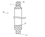
第1および第2の実施形態では、上記の通り、シールリング9は、矩形の断面を有するが、シールリングの断面は矩形には限定されない。図11および図12に示す変形例に係るシールリング26では、径方向外側の軸線方向の長さが大きく、径方向内側の軸線方向の長さが小さい。つまり、ハウジング2の孔3の内周面3Aに接触するシールリング26の外周面16の軸線方向の長さが内周面18の軸線方向の長さより大きい。したがって、シールリング26はT字形の断面を有する。
In the first and second embodiments, as described above, the
図13に示す変形例に係るシールリング26AもT字形の断面を有する。但し、シールリング26Aでは、径方向外側の軸線方向の長さが小さく、径方向内側の軸線方向の長さが大きい。
The
シールリング26Aでは、接合部7以外の外周面16に周方向に延びる2つの溝27が形成されており、2つの溝27の間に周方向に延びる突起28が形成されている。突起28の外周面は接合部7の外周面に円滑に連なる。突起28の外周面と接合部7の外周面は、シールリング26Aの外周面16を構成し、ハウジング2の孔3の内周面3Aに接触する。
In the
さらに、各溝27には、突起28と直交する方向に延びる複数のリブ29が形成されている。図13では、各溝27に1つのリブ29しか示されていないが、各溝27において、複数のリブ29が互いに間隔をおいて配置されている。リブ29は、溝27内部の潤滑油の流れを制御する。
Further, each
図14に示す変形例に係るシールリング26BはL字形の断面を有する。シールリング26Bは、図13に示すシールリング26Aの突起28が片側に偏った形状を有する。すなわち、シールリング26Bでは、接合部7以外の外周面16に周方向に延びる1つの溝31と、周方向に延びる突起32が形成されている。突起32の外周面は接合部7の外周面に円滑に連なる。突起32の外周面と接合部7の外周面は、シールリング26Bの外周面16を構成し、ハウジング2の孔3の内周面3Aに接触する。
The
さらに、溝31には、突起32と直交する方向に延びる複数のリブ33が形成されている。図14では、溝31に1つのリブ33しか示されていないが、溝31において、複数のリブ33が互いに間隔をおいて配置されている。リブ33は、溝31内部の潤滑油の流れを制御する。図14に示された端面10,12から明らかなように、溝31は大気空間B側に形成され、突起32は潤滑油空間A側に形成されている。
Further, the groove 31 is formed with a plurality of
図15から図19に示すように、シールリングはさらに複雑な形状を有していてもよい。 As shown in FIGS. 15 to 19, the seal ring may have a more complex shape.
図15および図16に示す変形例に係るシールリング36は、シールリング36の大気空間B側の端面12(図6参照)に形成された複数のT字形の溝40を有する。溝40は、周方向に間隔をおいて配置されている。他方、シールリング36の潤滑油空間A側の端面10は平坦である。
The
各溝40は、国際公開第2015/111707号に開示されたものと同様に、円弧状の長溝部41と、長溝部41の中央から径方向内側に向けて延びて内周面18で開口する短溝部42を有する。図16に示すように、長溝部41の深さは、長溝部41の中央ほど大きい。短溝部42の深さは、長溝部41の中央の深さよりさらに大きい。
Each
シールリング36の大気空間B側の端面12は、軸4の周溝8の大気空間B側の壁面に押し付けられるが、端面12と周溝8の大気空間B側の壁面の間には、潤滑油が侵入する。溝40が設けられたこの変形例では、静止したシールリング36に対する軸4の回転に伴って、長溝部41の一方の端部41aまたは41bには、短溝部42から潤滑油が侵入しやすい。具体的には、軸4が方向R1に回転すると、短溝部42を経て端部41aに潤滑油が侵入しやすく、軸4が方向R2に回転すると、短溝部42を経て端部41bに潤滑油が侵入しやすい。The
この結果、端面12と周溝8の大気空間B側の壁面の間には、油膜が発生する。端面12と周溝8の大気空間B側の壁面の間の薄い油膜は、軸4に与えられるトルクを低減させる。
As a result, an oil film is formed between the
シールリング36は、2つの起点20から接合部7に向けて厚さtが徐々に減少するよう形成されている。図15に示すように、長溝部41の幅W(シールリング36の径方向での長さ)および短溝部42の長さL(シールリング36の径方向での長さ)も、厚さtと同様に、2つの起点20から接合部7に向けて徐々に減少する。
The
図17に示す変形例に係るシールリング46も、シールリング46の大気空間B側の端面12(図6参照)に形成された複数のT字形の溝40を有する。溝40は、周方向に間隔をおいて配置されている。他方、シールリング46の潤滑油空間A側の端面10は平坦である。溝40の機能は上記と同様である。
The
図17に示す変形例では、長溝部41の幅W(シールリング36の径方向での長さ)は、シールリング46の周方向全体にわたって一定であり、短溝部42の長さL(シールリング36の径方向での長さ)が厚さtと同様に、2つの起点20から接合部7に向けて徐々に減少する。
In the modified example shown in FIG. 17, the width W (the length in the radial direction of the seal ring 36) of the
図18に示す変形例に係るシールリング56は、シールリング56の大気空間B側の端面12(図6参照)に形成された複数の溝60を有する。溝60は、周方向に間隔をおいて配置されている。各溝60は渦巻き状に延びて内周面18で開口する。他方、シールリング46の潤滑油空間A側の端面10は平坦である。
The
図18において、矢印Rは軸4の主回転方向(主に使用される回転方向)を示す。軸4の主回転方向とは、軸4が自動車の動力伝達軸である場合、自動車の前進時の動力伝達軸の回転方向である。
In FIG. 18, the arrow R indicates the main rotation direction (mainly used rotation direction) of the
シールリング56が自動車の右側に配置されるか左側に配置されるかに依存して、主回転方向は逆であることに留意されたい。主回転方向が図面と逆の場合には、溝60の向きも図面と逆である。
Note that the main rotation direction is opposite, depending on whether the
各溝60は、径方向内側に配置された内側端部60aと、径方向外側に配置された外側端部60bを有する。内側端部60aはシールリング56の内周面16で開口する。外側端部60bは閉鎖している(すなわち壁で包囲されている)。
Each
各溝60は、開口した内側端部60aから軸4の主回転方向と逆方向に向けて外側端部60bまで延びており、内側端部60aから主回転方向に向けて延びていない。したがって、軸4の回転に伴って、溝60の内側端部60aでの圧力が外側端部60bでの圧力より低下し、溝60に浸入した流体が排出されるようになっている。
Each
シールリング56の大気空間B側の端面12は、軸4の周溝8の大気空間B側の壁面に押し付けられるが、端面12と周溝8の大気空間B側の壁面の間には、潤滑油が侵入する。複数の溝60は、シールリング6に対する軸4の主回転方向Rへの回転に伴って、複数の溝60から潤滑油が排出されることを促す。これによって潤滑油の膜を薄くして剪断抵抗を低下させるとともに、キャビテーションにより潤滑油中の空気が気化することを促して、各溝60内のほぼ全域を占める空気の膜を形成する。空気の膜を構成する空気も、溝60から排出されるが、軸4の主回転方向Rへの回転が継続する限り、キャビテーションにより次々と気泡が発生するので、空気の膜が溝60内に持続的に存在する。端面12と周溝8の大気空間B側の壁面の間の薄い油膜および空気の膜は、軸4に与えられるトルクを低減させる。
The end face 12 on the atmospheric space B side of the
図19に示す変形例に係るシールリング66も、シールリング66の大気空間B側の端面12(図6参照)に形成された複数の溝60を有する。溝60は、周方向に間隔をおいて配置されている。各溝60は渦巻き状に延びて内周面18で開口する。他方、シールリング66の潤滑油空間A側の端面10は平坦である。溝60の機能は上記と同様である。
The
図18および図19に示すように、溝60の長さL(シールリングの径方向での長さ)は、シールリングの厚さtと同様に、2つの起点20から接合部7に向けて徐々に減少する。但し、図18では、複数の溝60の外側端部60bとシールリングの外周面16の距離Dが周方向全体にわたって一定であるが、図19では、複数の溝60の外側端部60bとシールリングの外周面16の距離Dが2つの起点20から接合部7に向けて徐々に減少する。したがって、溝60の長さLの減少率は、図18と図19では異なる。
As shown in FIGS. 18 and 19, the length L of the groove 60 (the length in the radial direction of the seal ring) is the same as the thickness t of the seal ring, from the two
第3の実施形態
図20に示すように、本発明の第3の実施形態に係る密封構造70は、ハウジング(外側部材)2、軸(内側部材)4、シールリング76を備える。ハウジング2は、固定された部材であり、円柱形の内周面3Aを有する孔3と、被密封潤滑油が内部に配置された潤滑油空間(液体空間)Aを有する。潤滑油空間Aは孔3に連通する。Third Embodiment As shown in FIG. 20, the sealing
潤滑油空間Aには軸4が配置されており、軸4は孔3に挿入されている。軸4は、中心軸Axの周囲を回転する回転軸であり、自動車の動力伝達軸である。
A
この実施形態では、軸4の周溝8の代わりに、ハウジング2の孔3の内周面3Aに周溝78が形成されている。周溝78には、樹脂製の円環状のシールリング76が配置されており、シールリング76には軸4が挿入されている。シールリング76は、軸4とハウジング2の間の隙間を封止して、ハウジング2の内部の潤滑油空間Aから大気空間Bへ潤滑油が漏出するのを防止または低減させる。
In this embodiment, the
シールリング76の径方向内側の部分は、周溝78から径方向内側に突出しており、シールリング76の内周面18は、軸4の外周面に接触する。シールリング76は、軸4に固定される。ここで、「固定される」とは、シールリング76の位置が軸4に対して静止していることを意味し、シールリング76が軸4に取り外し不能に結合されているか否かを限定する意図ではない。この実施形態では、シールリング76には軸4が締まり嵌めされる。さらに、後述するように、シールリング76はシールリング76の外側の潤滑油から圧力を受けることにより、軸4に固定されている。
The radial inner portion of the
シールリング76は、ハウジング2に対して摺動可能にハウジング2の周溝78内に配置されている。シールリング76は、潤滑油空間Aと大気空間Bを隔離し、潤滑油をハウジング2の潤滑油空間A内に閉じ込める。この密封構造70において、ハウジング2とシールリング76が固定されているのに対して、軸4はハウジング2に対して回転する。したがって、軸4とともにシールリング76も回転する。
The
この実施形態では、シールリング76は、矩形の断面を有する。シールリング76は、第1の実施形態および第2の実施形態のシールリング6と同じ材料から形成されている。
In this embodiment, the
図21に示すように、シールリング76は、長尺の円弧状の棒から、棒の両端部6A,6Bを接合することにより、円形をなすよう形成されている。したがって、シールリング76は、両端部6A,6Bから形成された接合部7を有する。このように、シールリング76は、無端リングではなく、円弧状の棒から形成されているので、シールリング76をハウジング2の孔3の内周面3Aに形成された周溝78に嵌め込み、かつシールリング76を軸4の周囲に配置するのが容易である。
As shown in FIG. 21, the
図21に示す端部6A,6Bの形状は、特殊ステップカットであるが、シールリング76の端部の形状は、特殊ステップカットに限定されず、ステップカット、ストレートカット、バイアスカットのいずれであってもよい。
The shape of the
図20に戻り、上記のように、シールリング76の内周面18は、軸4の外周面に接触させられている。シールリング76の外周面16と、軸4の周溝78の底面78aとの間には、潤滑油空間A内の潤滑油が流通可能な隙間があり、シールリング76はシールリング76の内側の潤滑油から外側に向けて圧力を受けるので、ハウジング2に強固に固定される。
Returning to FIG. 20, as described above, the inner
シールリング76の潤滑油空間A側の端面10には、潤滑油空間A内の潤滑油から油圧(矢印で示す)が与えられ、シールリング76は大気空間B側に押される。したがって、シールリング76の大気空間B側の端面12は、軸4の周溝78の大気空間B側の壁面に押し付けられる。但し、端面12と周溝78の大気空間B側の壁面の間には、潤滑油が浸入し、厳密には、端面12は周溝78の大気空間B側の壁面に面接触せず、両者の間には油膜が存在する。
Hydraulic pressure (indicated by an arrow) is applied to the
図21に示すように、この実施形態では、シールリング76の径方向の厚さtは、シールリング76の周方向にわたって一定ではない。第1の実施形態および第2の実施形態と同様に、ある2つの地点(起点)20から接合部7に向けて、厚さtは徐々に減少する。好ましくは、2つの地点20は、シールリング76の外周面16の中止軸線Cと接合部7を結ぶ線分Lに対して、対称位置にある。中止軸線Cは、ハウジング2の孔3内にシールリング76を配備すると、軸4と孔3の中心軸Axに合致する。
As shown in FIG. 21, in this embodiment, the radial thickness t of the
起点20での厚さtaよりも接合部7での厚さtbは小さい。起点20と接合部7の間の中間点での厚さtcは、厚さtaより小さく、厚さtbより大きい。他方、接合部7と反対側では、厚さtは、一様であり、起点20での厚さtaに等しい。The thickness t b at the
したがって、厚さtbはシールリング76の最小厚さであり、厚さtaはシールリング76の最大厚さである。Therefore, the thickness t b is the minimum thickness of the
図21において、2つの起点20は、円形の中止軸線Cを中心として、接合部7から90度離れている。つまり、中止軸線Cを中心とする起点20と接合部7の間の角度θは90度である。但し、角度θは、90度には限定されない。
In FIG. 21, the two
第1の実施形態に関するシミュレーション結果から、第3の実施形態においても、角度θは、60度以上、150度以下であることが好ましく、80度以上、120度以下であることがさらに好ましいと類推される。したがって、2つの起点20は、円形の中止軸線Cを中心として、接合部7から60度以上、150度以下の角度、離れていることが好ましく、接合部7から80度以上、120度以下の角度、離れていることがさらに好ましい。
From the simulation results of the first embodiment, it is inferred that the angle θ is preferably 60 degrees or more and 150 degrees or less, and more preferably 80 degrees or more and 120 degrees or less in the third embodiment as well. Will be done. Therefore, the two
また、第1の実施形態に関するシミュレーション結果から、第3の実施形態においても、起点20での厚さtaに対する接合部7での厚さtbの比率は、0.2以上、0.6以下であることが好ましく、0.3以上、0.5以下であることがさらに好ましいと類推される。Further, from the simulation results of the first embodiment, also in the third embodiment, the ratio of the thickness t b at the
シールリング76は、さらに外周面16から径方向外側に突出する2つの突起80を有する。突起80は2つの起点20の間に配置されている。好ましくは、突起80は接合部7の付近に配置されている。つまり、突起80と接合部7の間隔は、突起80と起点20の間隔よりも小さい。
The
シールリング76の内周面18は、中止軸線Cを中心とする円筒形であり、内周面18の半径Riは、シールリング76の周方向全体にわたって一定である。The inner
他方、シールリング76の外周面16の曲率半径Roは、中止軸線C周りで変化する。外周面16の曲率半径Roは、起点20から接合部7に向けて、徐々に減少する。起点20での曲率半径Roaよりも接合部7での曲率半径Robは小さい。起点20と接合部7の間の中間点での曲率半径Rocは、曲率半径Roaより小さく、曲率半径Robより大きい。接合部7と反対側では、曲率半径Roは、一様であり、起点20での曲率半径Roaに等しい。On the other hand, the radius of curvature Ro of the outer
したがって、曲率半径Robは外周面16の最小曲率半径であり、曲率半径Roaは外周面16の最大曲率半径である。Therefore, the radius of curvature R ob is the minimum radius of curvature of the outer
図21に、シールリング76の外周面16が中止軸線Cを中心とする円筒形であると仮定した場合の外周面16の輪郭16aを仮想線で示す。起点20よりも接合部7側において、この実施形態での内周面18は、輪郭16aよりも径方向外側に位置する。
FIG. 21 shows a virtual line showing the
このようにして、シールリング76は、接合部7から角度θ離れた地点20から接合部7に向けて厚さtが徐々に減少するよう形成されている。
In this way, the
この構成の下、シールリング76をハウジング2の孔3の内周面3Aの周溝78に配置した場合、シールリング76の内周面18が真円柱形に極めて近似し、軸4の外周面とシールリング76の内周面18の間の隙間が極めて小さい。したがって、シールリング76の封止性能が著しく高い。
Under this configuration, when the
図20から明らかなように、軸4の周溝78の底面78aとシールリング76の外周面16の間には隙間が許容され、両者の同軸度および接触は重要ではない。これに対して、軸4の外周面とシールリング76の内周面18の接触は、封止性能のために重要である。
As is clear from FIG. 20, a gap is allowed between the
図22は、組み立てるときの第3の実施形態に係る密封構造70の各部の断面図である。実施形態では、2つの起点20の間に突起80が配置されているので、接合部7が軸4の下方に位置するように、ハウジング2の孔3の内周面3Aの周溝78にシールリング76を配備すると、シールリング76の外周面16から突出する2つの突起80が周溝78の底面78aに接触する。2つの突起80は、シールリング76の厚さが減少する起点である2つの起点20の間に設けられているので、ハウジング2の孔3の内周面3Aの周溝78にシールリング76を配備すると、シールリング76の内周面18は、周溝78ひいては軸4の外周面にほぼ同心に配置される。したがって、矢印で示すように、軸4をシールリング76に挿入する際、軸4がシールリング76にぶつかりにくく、シールリング76の破損が防止または低減される。
FIG. 22 is a cross-sectional view of each part of the sealed
一方、図23は、組み立てるときの比較例に係る密封構造の各部の断面図である。この比較例では、突起80が設けられていない。したがって、接合部7が軸4の下方に位置するように、ハウジング2の孔3の内周面3Aの周溝78にシールリング76を配備すると、厚さが小さい接合部7の付近でシールリング76の外周面16が周溝78の底面78aに接触する。したがって、孔3の上部付近において、シールリング76が周溝78から大きく突出する。このため、矢印で示すように、軸4をシールリング76に挿入する際、軸4がシールリング76にぶつかりやすく、シールリング76が破損するおそれがある。
On the other hand, FIG. 23 is a cross-sectional view of each part of the sealed structure according to the comparative example at the time of assembling. In this comparative example, the
第3の実施形態では、上記の通り、シールリング76は、矩形の断面を有するが、シールリングの断面は矩形には限定されない。図24に示す変形例に係るシールリング86では、径方向内側の軸線方向の長さが大きく、径方向外側の軸線方向の長さが小さい。つまり、軸4の外周面に接触するシールリング76の内周面18の軸線方向の長さが外周面16の軸線方向の長さより大きい。したがって、シールリング86はT字形の断面を有する。
In the third embodiment, as described above, the
詳細な図示は省略するが、図13のシールリング26Aの内周と外周を逆にした形状のシールリング、ならびに図14のシールリング26Bの内周と外周を逆にした形状のシールリングも考えられる。
Although detailed illustration is omitted, a seal ring having the inner circumference and the outer circumference of the
詳細な図示は省略するが、シールリング76の大気空間B側の端面12(図20参照)に、図15から図17に示す溝40または図18もしくは図19に示す溝60に類似する複数の溝を形成してもよい。但し、第2の実施形態の変形例での溝40,60がシールリングの内周面18で開口するのに対して、第3の実施形態において、類似の溝を形成する場合には、溝はシールリングの外周面16で開口する。
Although detailed illustration is omitted, a plurality of
以上、本発明の好ましい実施形態を参照しながら本発明を図示して説明したが、当業者にとって特許請求の範囲に記載された発明の範囲から逸脱することなく、形式および詳細の変更が可能であることが理解されるであろう。このような変更、改変および修正は本発明の範囲に包含されるはずである。 Although the present invention has been illustrated and described above with reference to preferred embodiments of the present invention, those skilled in the art can change the form and details without departing from the scope of the invention described in the claims. It will be understood that there is. Such changes, modifications and modifications should be included within the scope of the invention.
例えば、上記の実施の形態においては、外側部材であるハウジング2とシールリングが固定されているのに対して、内側部材である軸4はハウジング2に対して回転する。しかし、本発明に係るシールリングは、固定された内側部材と回転する外側部材の間に配置され、回転する外側部材の内面に固定、例えば締まり嵌めされてもよい。
For example, in the above embodiment, the
図1では、シールリング6の端面10および端面12は平面として描かれているが、端面10および端面12の少なくとも一方には、図15から図17に示す溝40または図18もしくは図19に示す溝60に類似する複数の溝または複数の穴が形成されていてもよい。
In FIG. 1, the
図示しないが、第1の実施形態と第2の実施形態とその変形例において、軸4の周溝8の底面8aとシールリング6,9,26,26A,26B,36,46,56または66の内周面18の間に、弾性体(例えばエラストマー)から形成された他のリングを配置してもよい。この場合、シールリングはシールリングの内側の弾性体リングから外側に向けて圧力を受ける。
Although not shown, in the first embodiment, the second embodiment, and a modification thereof, the
図示しないが、第3の実施形態とその変形例において、ハウジング2の孔3の周溝78の底面78aとシールリング76または86の外周面16の間に、弾性体(例えばエラストマー)から形成された他のリングを配置してもよい。この場合、シールリングはシールリングの外側の弾性体リングから内側に向けて圧力を受ける。
Although not shown, in the third embodiment and its modifications, it is formed from an elastic body (for example, an elastomer) between the
第2の実施形態とその変形例において、突起22の数は2つに限定されず、3つ以上でもよい。第3の実施形態とその変形例において、突起80の数は2つに限定されず、3つ以上でもよい。
In the second embodiment and its modifications, the number of
本発明の態様は、下記の番号付けされた条項にも記載される。 Aspects of the invention are also described in the numbered clauses below.
条項1. 相対的に回転する外側部材と内側部材の間に配置される樹脂製の円環状のシールリングであって、
長尺の円弧状の棒から前記棒の両端部を接合することにより、円形をなすよう形成されており、前記両端部から形成された接合部を有し、
前記シールリングの径方向の厚さは、前記接合部から離れた2つの地点から前記接合部に向けて、徐々に減少しており、
前記地点は、前記円形の中心軸を中心として、前記接合部から60度以上、150度以下の角度、離れている
ことを特徴とするシールリング。
It is formed to form a circle by joining both ends of the rod from a long arc-shaped rod, and has a joint formed from both ends.
The radial thickness of the seal ring gradually decreases from two points away from the joint toward the joint.
The seal ring is characterized in that the point is separated from the joint portion by an angle of 60 degrees or more and 150 degrees or less with the circular central axis as the center.
条項2. 前記地点は、前記中心軸を中心として、前記接合部から80度以上、120度以下の角度、離れている
ことを特徴とする条項1に記載のシールリング。
条項3. 前記地点での前記厚さに対する前記接合部での前記厚さの比率は、0.2以上、0.6以下である
ことを特徴とする条項1または2に記載のシールリング。
条項4. 前記地点での前記厚さに対する前記接合部での前記厚さの比率は、0.3以上、0.5以下である
ことを特徴とする条項1または2に記載のシールリング。
条項5. 前記外側部材は、円柱形の内周面を有する孔と、前記孔に連通し液体が内部に配置された液体空間を有し、
前記内側部材は、前記液体空間に配置され、前記孔に挿入されており、
前記内側部材の外周面は、周溝を有しており、
前記シールリングは、前記外側部材に対して静止するように前記外側部材の前記孔に挿入されて、前記内側部材に対して摺動可能に前記内側部材の前記周溝内に配置されて、前記液体空間と外部空間を隔離する
ことを特徴とする条項1から4のいずれか1項に記載のシールリング。Clause 5. The outer member has a hole having a cylindrical inner peripheral surface and a liquid space in which a liquid communicates with the hole and is arranged inside.
The inner member is arranged in the liquid space and inserted into the hole.
The outer peripheral surface of the inner member has a peripheral groove and has a peripheral groove.
The seal ring is inserted into the hole of the outer member so as to be stationary with respect to the outer member, and is slidably arranged in the peripheral groove of the inner member so as to be slidable with respect to the inner member. The seal ring according to any one of
条項6. 前記シールリングは、前記中心軸を中心とする円筒形の外周面と、曲率半径が前記中心軸周りで変化する内周面を有しており、前記シールリングの前記内周面の曲率半径は、前記地点から前記接合部に向けて、徐々に増加する
ことを特徴とする条項5に記載のシールリング。
条項7. 内周面から径方向内側に突出する複数の突起をさらに有し、
前記突起は、前記2つの地点の間に配置されている
ことを特徴とする条項5または6に記載のシールリング。
条項8. 前記突起と前記接合部の間隔は、前記突起と前記地点の間隔よりも小さい
ことを特徴とする条項7に記載のシールリング。
The seal ring according to
条項9. 前記外側部材は、円柱形の内周面を有する孔と、前記孔に連通し、液体が内部に配置された液体空間を有し、
前記内側部材は、前記液体空間に配置され、前記孔に挿入されており、
前記外側部材の前記孔の内周面は、周溝を有しており、
前記シールリングは、前記外側部材に対して摺動可能に前記外側部材の前記周溝内に配置され、前記液体空間と外部空間を隔離し、前記シールリングに前記内側部材が挿入されて前記内側部材に対して前記シールリングは静止している
ことを特徴とする条項1から4のいずれか1項に記載のシールリング。
The inner member is arranged in the liquid space and inserted into the hole.
The inner peripheral surface of the hole of the outer member has a peripheral groove.
The seal ring is slidably arranged in the peripheral groove of the outer member to separate the liquid space from the outer space, and the inner member is inserted into the seal ring to insert the inner member into the inner groove. The seal ring according to any one of
条項10. 前記シールリングは、前記中心軸を中心とする円筒形の内周面と、曲率半径が前記中心軸周りで変化する外周面を有しており、前記シールリングの前記外周面の曲率半径は、前記地点から前記接合部に向けて、徐々に減少する
ことを特徴とする条項9に記載のシールリング。
条項11. 外周面から径方向外側に突出する複数の突起をさらに有し、
前記突起は、前記2つの地点の間に配置されている
ことを特徴とする条項9または10に記載のシールリング。Clause 11. Further having a plurality of protrusions protruding radially outward from the outer peripheral surface,
The seal ring according to
条項12. 前記突起と前記接合部の間隔は、前記突起と前記地点の間隔よりも小さい
ことを特徴とする条項11に記載のシールリング。
A 潤滑油空間(液体空間)
B 外部空間
1,70 密封構造
2 ハウジング(外側部材)
3 孔
3A 内周面
4 軸(内側部材)
6,9,26,26A,26B,36,46,56,66 シールリング
6A 端部
6B 端部
7 接合部
8 周溝
8a 底面
16 外周面
18 内周面
20 起点(地点)
22 突起
76,86 シールリング
78 周溝
78a 底面
80 突起
A Lubricating oil space (liquid space)
3
6,9,26,26A, 26B, 36,46,56,66
22
Claims (12)
長尺の円弧状の棒から前記棒の両端部を接合することにより、円形をなすよう形成されており、前記両端部から形成された接合部を有し、
前記シールリングの径方向の厚さは、前記接合部から離れた2つの地点から前記接合部に向けて、徐々に減少しており、
前記地点は、前記円形の中心軸を中心として、前記接合部から60度以上、150度以下の角度、離れている
ことを特徴とするシールリング。A resin annular seal ring placed between the relatively rotating outer and inner members.
It is formed to form a circle by joining both ends of the rod from a long arc-shaped rod, and has a joint formed from both ends.
The radial thickness of the seal ring gradually decreases from two points away from the joint toward the joint.
The seal ring is characterized in that the point is separated from the joint portion by an angle of 60 degrees or more and 150 degrees or less with the circular central axis as the center.
ことを特徴とする請求項1に記載のシールリング。The seal ring according to claim 1, wherein the point is separated from the joint portion by an angle of 80 degrees or more and 120 degrees or less with respect to the central axis.
ことを特徴とする請求項1または2に記載のシールリング。The seal ring according to claim 1 or 2, wherein the ratio of the thickness at the joint to the thickness at the point is 0.2 or more and 0.6 or less.
ことを特徴とする請求項1または2に記載のシールリング。The seal ring according to claim 1 or 2, wherein the ratio of the thickness at the joint to the thickness at the point is 0.3 or more and 0.5 or less.
前記内側部材は、前記液体空間に配置され、前記孔に挿入されており、
前記内側部材の外周面は、周溝を有しており、
前記シールリングは、前記外側部材に対して静止するように前記外側部材の前記孔に挿入されて、前記内側部材に対して摺動可能に前記内側部材の前記周溝内に配置されて、前記液体空間と外部空間を隔離する
ことを特徴とする請求項1から4のいずれか1項に記載のシールリング。The outer member has a hole having a cylindrical inner peripheral surface and a liquid space in which a liquid communicates with the hole and is arranged inside.
The inner member is arranged in the liquid space and inserted into the hole.
The outer peripheral surface of the inner member has a peripheral groove and has a peripheral groove.
The seal ring is inserted into the hole of the outer member so as to be stationary with respect to the outer member, and is slidably arranged in the peripheral groove of the inner member so as to be slidable with respect to the inner member. The seal ring according to any one of claims 1 to 4, wherein the liquid space and the external space are separated from each other.
ことを特徴とする請求項5に記載のシールリング。The seal ring has a cylindrical outer peripheral surface centered on the central axis and an inner peripheral surface whose radius of curvature changes around the central axis, and the radius of curvature of the inner peripheral surface is from the above point. The seal ring according to claim 5, wherein the seal ring gradually increases toward the joint portion.
前記突起は、前記2つの地点の間に配置されている
ことを特徴とする請求項5または6に記載のシールリング。Further having a plurality of protrusions protruding radially inward from the inner peripheral surface,
The seal ring according to claim 5 or 6, wherein the protrusion is arranged between the two points.
ことを特徴とする請求項7に記載のシールリング。The seal ring according to claim 7, wherein the distance between the protrusion and the joint is smaller than the distance between the protrusion and the point.
前記内側部材は、前記液体空間に配置され、前記孔に挿入されており、
前記外側部材の前記孔の内周面は、周溝を有しており、
前記シールリングは、前記外側部材に対して摺動可能に前記外側部材の前記周溝内に配置され、前記液体空間と外部空間を隔離し、前記シールリングに前記内側部材が挿入されて前記内側部材に対して前記シールリングは静止している
ことを特徴とする請求項1から4のいずれか1項に記載のシールリング。The outer member has a hole having a cylindrical inner peripheral surface and a liquid space communicating with the hole and arranging a liquid inside.
The inner member is arranged in the liquid space and inserted into the hole.
The inner peripheral surface of the hole of the outer member has a peripheral groove.
The seal ring is slidably arranged in the peripheral groove of the outer member to separate the liquid space from the outer space, and the inner member is inserted into the seal ring to insert the inner member into the inner groove. The seal ring according to any one of claims 1 to 4, wherein the seal ring is stationary with respect to the member.
ことを特徴とする請求項9に記載のシールリング。The seal ring has a cylindrical inner peripheral surface centered on the central axis and an outer peripheral surface whose radius of curvature changes around the central axis, and the radius of curvature of the outer peripheral surface is the said from the point. The seal ring according to claim 9, wherein the seal ring gradually decreases toward the joint.
前記突起は、前記2つの地点の間に配置されている
ことを特徴とする請求項9または10に記載のシールリング。Further having a plurality of protrusions protruding radially outward from the outer peripheral surface,
The seal ring according to claim 9 or 10, wherein the protrusion is arranged between the two points.
ことを特徴とする請求項11に記載のシールリング。
11. The seal ring according to claim 11, wherein the distance between the protrusion and the joint is smaller than the distance between the protrusion and the point.
Applications Claiming Priority (5)
| Application Number | Priority Date | Filing Date | Title |
|---|---|---|---|
| JP2019130173 | 2019-07-12 | ||
| JP2019130173 | 2019-07-12 | ||
| JP2020008914 | 2020-01-23 | ||
| JP2020008914 | 2020-01-23 | ||
| PCT/JP2020/019122 WO2021010005A1 (en) | 2019-07-12 | 2020-05-13 | Seal ring |
Publications (2)
| Publication Number | Publication Date |
|---|---|
| JPWO2021010005A1 JPWO2021010005A1 (en) | 2021-01-21 |
| JP6999068B2 true JP6999068B2 (en) | 2022-02-04 |
Family
ID=74210404
Family Applications (1)
| Application Number | Title | Priority Date | Filing Date |
|---|---|---|---|
| JP2021532696A Active JP6999068B2 (en) | 2019-07-12 | 2020-05-13 | Seal ring |
Country Status (6)
| Country | Link |
|---|---|
| US (2) | US12104698B2 (en) |
| EP (1) | EP3998418B1 (en) |
| JP (1) | JP6999068B2 (en) |
| KR (1) | KR102656388B1 (en) |
| CN (1) | CN114072602B (en) |
| WO (1) | WO2021010005A1 (en) |
Families Citing this family (3)
| Publication number | Priority date | Publication date | Assignee | Title |
|---|---|---|---|---|
| IT201800002027A1 (en) * | 2018-01-26 | 2019-07-26 | Turboden Spa | Fluid seal device for rotating machines |
| MX2021009032A (en) * | 2019-01-29 | 2021-10-26 | Hoerbiger Wien Gmbh | Packaging ring with wear opening. |
| JP7550344B1 (en) | 2022-12-16 | 2024-09-12 | Nok株式会社 | Seal ring |
Citations (2)
| Publication number | Priority date | Publication date | Assignee | Title |
|---|---|---|---|---|
| JP2013540242A (en) | 2010-09-27 | 2013-10-31 | フェデラル−モーグル ブルシャイト ゲゼルシャフト ミット ベシュレンクテル ハフツング | Piston ring manufacturing method |
| JP2015218791A (en) | 2014-05-15 | 2015-12-07 | Nok株式会社 | Seal ring |
Family Cites Families (19)
| Publication number | Priority date | Publication date | Assignee | Title |
|---|---|---|---|---|
| US4165079A (en) * | 1978-08-02 | 1979-08-21 | General Motors Corporation | Fluid seal ring |
| JPS61165071A (en) * | 1985-01-12 | 1986-07-25 | Nissan Motor Co Ltd | Sealing structure for cover and the like |
| JP4299118B2 (en) * | 2003-12-18 | 2009-07-22 | Ntn株式会社 | Manufacturing method of resin seal ring |
| JP2006112486A (en) * | 2004-10-13 | 2006-04-27 | Nok Corp | Sealing device |
| JP5088075B2 (en) * | 2007-10-02 | 2012-12-05 | Nok株式会社 | Seal ring |
| AT506811B1 (en) * | 2008-09-25 | 2009-12-15 | Hoerbiger Kompressortech Hold | PRESSURE PACK OF UNPACKED PACKING RINGS WITH SPLASHED SEGMENTS |
| CN101747570B (en) * | 2008-12-18 | 2013-12-18 | 株式会社阪上制作所 | Sliding part and sealing device |
| AT507431B1 (en) * | 2009-01-29 | 2010-05-15 | Hoerbiger Kompressortechnik | SEGMENTED PACKING RING |
| DE102009012462A1 (en) * | 2009-03-12 | 2010-10-07 | Hytrac Gmbh | Rotary feedthrough and sealing element for a rotary feedthrough |
| EP2960554B1 (en) * | 2013-02-20 | 2019-06-19 | Nok Corporation | Sealing device |
| EP3098486B1 (en) | 2014-01-24 | 2020-03-11 | NOK Corporation | Sealing ring |
| JP6357865B2 (en) * | 2014-05-15 | 2018-07-18 | Nok株式会社 | Seal ring |
| JP6386416B2 (en) * | 2014-06-12 | 2018-09-05 | 三菱電線工業株式会社 | Seal ring |
| WO2016113923A1 (en) * | 2015-01-14 | 2016-07-21 | Nok株式会社 | Seal ring and sealing structure |
| JP6360566B2 (en) * | 2015-03-31 | 2018-07-18 | 株式会社リケン | Seal ring |
| JP6223633B1 (en) * | 2017-03-13 | 2017-11-01 | Tpr株式会社 | Seal ring and sealing device |
| KR102362482B1 (en) * | 2017-06-27 | 2022-02-11 | 엔오케이 가부시키가이샤 | seal ring |
| WO2020032236A1 (en) * | 2018-08-09 | 2020-02-13 | Nok株式会社 | Seal ring |
| CN109630280A (en) * | 2018-12-14 | 2019-04-16 | 中国航发沈阳发动机研究所 | Sealing element and sealing device |
-
2020
- 2020-05-13 CN CN202080049213.7A patent/CN114072602B/en active Active
- 2020-05-13 WO PCT/JP2020/019122 patent/WO2021010005A1/en unknown
- 2020-05-13 EP EP20839557.4A patent/EP3998418B1/en active Active
- 2020-05-13 JP JP2021532696A patent/JP6999068B2/en active Active
- 2020-05-13 KR KR1020227000021A patent/KR102656388B1/en active IP Right Grant
- 2020-05-13 US US17/623,715 patent/US12104698B2/en active Active
-
2024
- 2024-04-12 US US18/633,944 patent/US20240263703A1/en active Pending
Patent Citations (2)
| Publication number | Priority date | Publication date | Assignee | Title |
|---|---|---|---|---|
| JP2013540242A (en) | 2010-09-27 | 2013-10-31 | フェデラル−モーグル ブルシャイト ゲゼルシャフト ミット ベシュレンクテル ハフツング | Piston ring manufacturing method |
| JP2015218791A (en) | 2014-05-15 | 2015-12-07 | Nok株式会社 | Seal ring |
Also Published As
| Publication number | Publication date |
|---|---|
| KR20220016947A (en) | 2022-02-10 |
| CN114072602A (en) | 2022-02-18 |
| US12104698B2 (en) | 2024-10-01 |
| EP3998418A1 (en) | 2022-05-18 |
| US20220243819A1 (en) | 2022-08-04 |
| WO2021010005A1 (en) | 2021-01-21 |
| US20240263703A1 (en) | 2024-08-08 |
| JPWO2021010005A1 (en) | 2021-01-21 |
| CN114072602B (en) | 2024-04-05 |
| EP3998418B1 (en) | 2024-01-03 |
| EP3998418C0 (en) | 2024-01-03 |
| EP3998418A4 (en) | 2022-08-31 |
| KR102656388B1 (en) | 2024-04-12 |
Similar Documents
| Publication | Publication Date | Title |
|---|---|---|
| JP6999068B2 (en) | Seal ring | |
| US7770898B2 (en) | Stabilizing geometry for hydrodynamic rotary seals | |
| US7425003B2 (en) | Over center high deflection pressure energizing low leakage seal | |
| JP5801033B2 (en) | Seal structure | |
| CN108884940B (en) | Sealing ring | |
| JP5807095B2 (en) | SEAL RING AND SEALING DEVICE | |
| WO2020189148A1 (en) | Seal ring and sealing structure | |
| US20140175755A1 (en) | Shaft seal ring with anti-rotation features | |
| JP4580711B2 (en) | Electric motor fuel pump | |
| JP6170271B2 (en) | Seal ring | |
| JP7550344B1 (en) | Seal ring | |
| JP6081681B1 (en) | Seal ring | |
| JP6723237B2 (en) | Compressor and its usage | |
| US20240288074A1 (en) | Sealing ring and sealed structure including same | |
| JP6783273B2 (en) | Seal ring | |
| JP6865122B2 (en) | Sealed structure | |
| JP2020176694A (en) | Sealing device | |
| JP2019100206A (en) | Vane pump | |
| JP2017101736A (en) | Seal ring | |
| JPH10231838A (en) | Bearing and manufacture thereof |
Legal Events
| Date | Code | Title | Description |
|---|---|---|---|
| A521 | Request for written amendment filed |
Free format text: JAPANESE INTERMEDIATE CODE: A523 Effective date: 20211104 |
|
| A621 | Written request for application examination |
Free format text: JAPANESE INTERMEDIATE CODE: A621 Effective date: 20211104 |
|
| A871 | Explanation of circumstances concerning accelerated examination |
Free format text: JAPANESE INTERMEDIATE CODE: A871 Effective date: 20211104 |
|
| A01 | Written decision to grant a patent or to grant a registration (utility model) |
Free format text: JAPANESE INTERMEDIATE CODE: A01 Effective date: 20211207 |
|
| A61 | First payment of annual fees (during grant procedure) |
Free format text: JAPANESE INTERMEDIATE CODE: A61 Effective date: 20211221 |