JP6998714B2 - Image forming device and its control method, and program - Google Patents
Image forming device and its control method, and program Download PDFInfo
- Publication number
- JP6998714B2 JP6998714B2 JP2017188363A JP2017188363A JP6998714B2 JP 6998714 B2 JP6998714 B2 JP 6998714B2 JP 2017188363 A JP2017188363 A JP 2017188363A JP 2017188363 A JP2017188363 A JP 2017188363A JP 6998714 B2 JP6998714 B2 JP 6998714B2
- Authority
- JP
- Japan
- Prior art keywords
- print job
- setting
- reserved
- storage unit
- Prior art date
- Legal status (The legal status is an assumption and is not a legal conclusion. Google has not performed a legal analysis and makes no representation as to the accuracy of the status listed.)
- Active
Links
Images


Classifications
-
- G—PHYSICS
- G06—COMPUTING; CALCULATING OR COUNTING
- G06F—ELECTRIC DIGITAL DATA PROCESSING
- G06F3/00—Input arrangements for transferring data to be processed into a form capable of being handled by the computer; Output arrangements for transferring data from processing unit to output unit, e.g. interface arrangements
- G06F3/12—Digital output to print unit, e.g. line printer, chain printer
- G06F3/1201—Dedicated interfaces to print systems
- G06F3/1223—Dedicated interfaces to print systems specifically adapted to use a particular technique
- G06F3/1237—Print job management
- G06F3/1238—Secure printing, e.g. user identification, user rights for device usage, unallowed content, blanking portions or fields of a page, releasing held jobs
-
- G—PHYSICS
- G06—COMPUTING; CALCULATING OR COUNTING
- G06F—ELECTRIC DIGITAL DATA PROCESSING
- G06F3/00—Input arrangements for transferring data to be processed into a form capable of being handled by the computer; Output arrangements for transferring data from processing unit to output unit, e.g. interface arrangements
- G06F3/12—Digital output to print unit, e.g. line printer, chain printer
- G06F3/1201—Dedicated interfaces to print systems
- G06F3/1202—Dedicated interfaces to print systems specifically adapted to achieve a particular effect
- G06F3/1222—Increasing security of the print job
-
- G—PHYSICS
- G06—COMPUTING; CALCULATING OR COUNTING
- G06F—ELECTRIC DIGITAL DATA PROCESSING
- G06F3/00—Input arrangements for transferring data to be processed into a form capable of being handled by the computer; Output arrangements for transferring data from processing unit to output unit, e.g. interface arrangements
- G06F3/12—Digital output to print unit, e.g. line printer, chain printer
- G06F3/1201—Dedicated interfaces to print systems
- G06F3/1223—Dedicated interfaces to print systems specifically adapted to use a particular technique
- G06F3/1237—Print job management
- G06F3/1253—Configuration of print job parameters, e.g. using UI at the client
-
- G—PHYSICS
- G06—COMPUTING; CALCULATING OR COUNTING
- G06F—ELECTRIC DIGITAL DATA PROCESSING
- G06F3/00—Input arrangements for transferring data to be processed into a form capable of being handled by the computer; Output arrangements for transferring data from processing unit to output unit, e.g. interface arrangements
- G06F3/12—Digital output to print unit, e.g. line printer, chain printer
- G06F3/1201—Dedicated interfaces to print systems
- G06F3/1223—Dedicated interfaces to print systems specifically adapted to use a particular technique
- G06F3/1237—Print job management
- G06F3/1267—Job repository, e.g. non-scheduled jobs, delay printing
-
- G—PHYSICS
- G06—COMPUTING; CALCULATING OR COUNTING
- G06F—ELECTRIC DIGITAL DATA PROCESSING
- G06F3/00—Input arrangements for transferring data to be processed into a form capable of being handled by the computer; Output arrangements for transferring data from processing unit to output unit, e.g. interface arrangements
- G06F3/12—Digital output to print unit, e.g. line printer, chain printer
- G06F3/1201—Dedicated interfaces to print systems
- G06F3/1223—Dedicated interfaces to print systems specifically adapted to use a particular technique
- G06F3/1237—Print job management
- G06F3/1274—Deleting of print job
-
- G—PHYSICS
- G06—COMPUTING; CALCULATING OR COUNTING
- G06F—ELECTRIC DIGITAL DATA PROCESSING
- G06F3/00—Input arrangements for transferring data to be processed into a form capable of being handled by the computer; Output arrangements for transferring data from processing unit to output unit, e.g. interface arrangements
- G06F3/12—Digital output to print unit, e.g. line printer, chain printer
- G06F3/1201—Dedicated interfaces to print systems
- G06F3/1278—Dedicated interfaces to print systems specifically adapted to adopt a particular infrastructure
- G06F3/1285—Remote printer device, e.g. being remote from client or server
Description
本発明は、画像形成装置及びその制御方法、並びにプログラムに関し、特に、留め置き印刷を行う画像形成装置及びその制御方法、並びにプログラムに関する。 The present invention relates to an image forming apparatus and a control method thereof, and a program, and more particularly to an image forming apparatus for performing retention printing and a control method thereof, and a program.
取得した印刷ジョブデータの予約印刷を行う画像形成装置としてのMFPが知られている。予約印刷では上記印刷ジョブデータに設定された指定時刻に上記印刷ジョブデータの印刷が開始される。ユーザが、例えば、大量の印刷を行う際に、MFPの利用量が比較的少ない深夜や昼休みの時間帯を指定時刻に設定することにより、他のユーザがMFPを利用する際の妨げになるのを防止可能となる。一方で、予約印刷では、ユーザがMFPから離れていても、印刷が開始されてしまうため、印刷物が放置される可能性が極めて高く、放置された印刷物を悪意ある他のユーザが盗み見るといった情報漏洩のリスクが高まる。これに対し、受信した全ての印刷ジョブデータに対して留め置き印刷を行う動作モード(以下、「強制留め置きモード」という。)を備えるMFP(以下、「強制留め置きMFP」という。)が開発されている。強制留め置きMFPでは、管理者が強制留め置きMFPを利用する環境におけるセキュリティーポリシーに従って強制留め置きモードの有効及び無効の設定を行う。例えば、印刷物の放置を許容しないようなセキュリティレベルの高い環境で利用される場合、強制留め置きMFPでは強制留め置きモードが有効に設定される。強制留め置きモードが有効に設定されると、強制留め置きMFPは印刷ジョブデータを受信した際に該印刷ジョブデータの印刷を即座に行わず、上記印刷ジョブデータを強制留め置きMFPの記憶部に一時的に格納する。強制留め置きMFPはユーザが強制留め置きMFPの操作部によって印刷指示を行った際に上記印刷ジョブデータの印刷を開始する(例えば、特許文献1参照)。これにより、ユーザがMFPから離れている際に印刷が開始されることに起因する印刷物の放置を抑制可能となる。 An MFP is known as an image forming apparatus that performs scheduled printing of acquired print job data. In scheduled printing, printing of the print job data is started at a designated time set in the print job data. For example, when a user prints a large amount of data, setting a time zone such as midnight or lunch break when the amount of the MFP is relatively low at a specified time hinders other users from using the MFP. Can be prevented. On the other hand, in reserved printing, printing is started even if the user is away from the MFP, so there is an extremely high possibility that the printed matter will be left unattended, and information leakage such as a malicious other user snooping on the left printed matter. Risk increases. On the other hand, an MFP (hereinafter referred to as "forced retention MFP") having an operation mode (hereinafter referred to as "forced retention mode") for performing retention printing on all received print job data has been developed. .. In the forced detention MFP, the administrator sets whether the forced detention mode is enabled or disabled according to the security policy in the environment where the forced detention MFP is used. For example, when the printed matter is used in an environment with a high security level that does not allow the printed matter to be left unattended, the forced retention mode is effectively set in the forced retention MFP. When the forced retention mode is enabled, the forced retention MFP does not immediately print the print job data when it receives the print job data, and temporarily stores the print job data in the storage unit of the forced retention MFP. Store. The forced retention MFP starts printing the print job data when the user gives a print instruction by the operation unit of the forced retention MFP (see, for example, Patent Document 1). This makes it possible to suppress the leaving of the printed matter due to the start of printing when the user is away from the MFP.
しかしながら、従来の強制留め置きMFPでは、強制留め置きモードが機能せず、印刷物が放置されてしまう場合がある。ここで、例えば、強制留め置きモードが無効から有効に切り替えられた場合、強制留め置きモードが無効時に受信した印刷ジョブデータに対しても留め置き印刷を行う必要がある。ところが、従来の強制留め置きMFPでは、強制留め置きモードの設定に関わらず、強制留め置きモードが無効時に受信した印刷ジョブデータの指定時刻に上記印刷ジョブデータの印刷を開始してしまう。すなわち、従来の強制留め置きMFPでは、強制留め置きモードが有効に切り替わる前に受信した印刷ジョブデータに対する強制留め置きモードが機能せず、印刷物が放置されるという問題が生じる。 However, in the conventional forced retention MFP, the forced retention mode does not work, and the printed matter may be left unattended. Here, for example, when the forced retention mode is switched from invalid to enabled, it is necessary to perform retention printing on the print job data received when the forced retention mode is disabled. However, in the conventional forced retention MFP, printing of the print job data is started at a specified time of the print job data received when the forced retention mode is disabled, regardless of the setting of the forced retention mode. That is, in the conventional forced retention MFP, the forced retention mode for the print job data received before the forced retention mode is effectively switched does not work, and the printed matter is left unattended.
本発明の目的は、強制留め置きモードが機能しないことに起因する印刷物の放置を抑制することができる画像形成装置及びその制御方法、並びにプログラムを提供することにある。 An object of the present invention is to provide an image forming apparatus, a control method thereof, and a program capable of suppressing the leaving of printed matter due to the forced retention mode not functioning.
上記目的を達成するために、本発明の画像形成装置は、記憶部を備える画像形成装置であって、印刷ジョブを受信した際に前記印刷ジョブを前記記憶部に保存し、ユーザによる印刷指示に応じて前記印刷ジョブを実行する第1設定、及び、前記印刷ジョブを受信した際に前記印刷ジョブを前記記憶部に保存することなく前記印刷ジョブを実行する第2設定の何れかを設定する設定手段と、情報処理装置から印刷ジョブを受信する受信手段と、前記第2設定が設定されていて、かつ、前記受信した印刷ジョブが、印刷開始時刻が指定される予約印刷ジョブである場合、前記受信した印刷ジョブを前記記憶部に格納する格納手段と、ユーザからの印刷指示なしに、前記格納された予約印刷ジョブを、前記指定される前記印刷開始時刻に実行する実行手段と、前記格納された予約印刷ジョブの実行前に前記設定手段による設定が前記第2設定から前記第1設定に変更された場合、当該予約印刷ジョブを削除する削除手段と、を有することを特徴とする。 In order to achieve the above object, the image forming apparatus of the present invention is an image forming apparatus provided with a storage unit, and when a print job is received, the print job is stored in the storage unit, and a user gives a print instruction. A setting for setting either the first setting for executing the print job or the second setting for executing the print job without saving the print job in the storage unit when the print job is received. When the means, the receiving means for receiving the print job from the information processing apparatus, and the second setting are set, and the received print job is a reserved print job for which the print start time is specified, the above-mentioned A storage means for storing the received print job in the storage unit, an execution means for executing the stored reserved print job at the designated print start time without a print instruction from the user, and the storage. It is characterized by having a deletion means for deleting the reserved print job when the setting by the setting means is changed from the second setting to the first setting before the execution of the reserved print job.
また、本発明の画像形成装置は、記憶部を備える画像形成装置であって、記憶部を備える画像形成装置であって、印刷ジョブを受信した際に前記印刷ジョブを前記記憶部に保存し、ユーザによる印刷指示に応じて前記印刷ジョブを実行する第1設定、及び、前記印刷ジョブを受信した際に前記印刷ジョブを前記記憶部に保存することなく前記印刷ジョブを実行する第2設定の何れかを設定する設定手段と、情報処理装置から印刷ジョブを受信する受信手段と、前記第2設定が設定されていて、かつ、前記受信した印刷ジョブが、印刷開始時刻が指定される予約印刷ジョブである場合、前記受信した印刷ジョブを前記記憶部に格納する格納手段と、前記記憶部に格納された予約印刷ジョブの属性情報を管理する管理手段と、ユーザからの印刷指示なしに、前記格納された予約印刷ジョブを、前記指定される前記印刷開始時刻に実行する実行手段と、を備え、前記管理手段は、前記格納された予約印刷ジョブの実行前に前記設定手段による設定が前記第2設定から前記第1設定に変更された場合、当該予約印刷ジョブの属性情報を、ユーザによる印刷指示に応じて印刷を開始する旨を示す属性情報に変更することを特徴とする。 Further, the image forming apparatus of the present invention is an image forming apparatus including a storage unit, and is an image forming apparatus including a storage unit, and when a print job is received, the print job is stored in the storage unit. Either the first setting for executing the print job in response to a print instruction by the user, or the second setting for executing the print job when the print job is received without saving the print job in the storage unit. A setting means for setting the printing job, a receiving means for receiving a print job from the information processing apparatus, and a reserved print job for which the second setting is set and the print start time is specified for the received print job. If this is the case, the storage means for storing the received print job in the storage unit, the management means for managing the attribute information of the reserved print job stored in the storage unit, and the storage without a print instruction from the user. The second is provided with an execution means for executing the reserved print job at the designated print start time, and the management means is set by the setting means before the execution of the stored reserved print job. When the setting is changed to the first setting , the attribute information of the reserved print job is changed to the attribute information indicating that printing is started in response to a print instruction by the user.
本発明によれば、強制留め置きモードが機能しないことに起因する印刷物の放置を抑制することができる。 According to the present invention, it is possible to suppress the leaving of printed matter due to the forced retention mode not functioning.
以下、本発明の実施の形態を図面を参照しながら詳述する。 Hereinafter, embodiments of the present invention will be described in detail with reference to the drawings.
図1は、本発明の実施の形態に係る画像形成装置としてのMFP12のネットワーク構成を説明するための図である。
FIG. 1 is a diagram for explaining a network configuration of an
図1において、PC11及びMFP12はLAN13を介して接続されている。PC11はジョブの実行に用いられるジョブデータを生成し、生成したジョブデータをLAN13を介してMFP12等に送信する。PC11は、例えば、MFP12に印刷処理を実行させる印刷ジョブデータを生成する。
In FIG. 1, the PC 11 and the MFP 12 are connected via the
MFP12は、印刷機能、スキャン機能、及び通信機能等の複数の機能を備える。MFP12は、例えば、PC11から印刷ジョブデータを受信すると、上記印刷ジョブデータを用いて印刷処理を実行する。印刷ジョブデータには、通常印刷や留め置き印刷といった出力方法(属性情報)が設定されている。MFP12は、出力方法に通常印刷が設定された印刷ジョブデータ(以下、「通常印刷ジョブデータ」という。)を受信すると、上記通常印刷ジョブデータを用いた印刷処理を即座に実行する。一方、MFP12は、出力方法に留め置き印刷が設定された印刷ジョブデータ(以下、「留め置き印刷ジョブデータ」という。)を受信すると、上記留め置き印刷ジョブデータを用いた印刷処理を即座に実行しない。MFP12は上記留め置き印刷ジョブデータを後述する図3の記憶部304に一時的に格納し、MFP12にログインしたユーザによる印刷指示を受け付けた際に上記留め置き印刷ジョブデータを用いた印刷処理を実行する。
The MFP 12 has a plurality of functions such as a printing function, a scanning function, and a communication function. When the
また、MFP12は、上述したように印刷ジョブデータに設定された出力方法に対応する印刷処理を行う通常印刷モードの他に、印刷物の放置を許容しない強制留め置きモードを備える。MFP12では、強制留め置きモードが設定されると、受信した印刷ジョブデータが通常印刷ジョブデータであっても、上記通常印刷ジョブデータを用いた印刷処理を即座に実行しない。MFP12は上記通常印刷ジョブデータを後述する記憶部304に一時的に格納し、MFP12にログインしたユーザによる印刷指示を受け付けた際に上記通常印刷ジョブデータを用いた印刷処理を実行する。すなわち、本実施の形態では、強制留め置きモードの設定中に受信した全ての印刷ジョブデータが留め置き印刷ジョブデータとして処理される。
Further, the
図2は、図1のPC11のハードウェア構成を概略的に示すブロック図である。 FIG. 2 is a block diagram schematically showing the hardware configuration of the PC 11 of FIG.
図2において、PC11はCPU201、RAM202、記憶部203、表示部204、操作部205、及びNIC(Network Interface Card)206を備える。CPU201、RAM202、記憶部203、表示部204、操作部205、及びNIC206はメインバス207を介して互いに接続されている。
In FIG. 2, the PC 11 includes a
CPU201は後述する図6のソフトウェアモジュール600の各処理を制御する。RAM202はCPU201の作業領域として、また、各データの一時格納領域として用いられる。記憶部203は、ハードディスク、フロッピーディスク、及びCD-ROM等の補助記憶装置であり、CPU201によって実行されるプログラム等を格納する。表示部204はCRTディスプレイや液晶ディスプレイ等であり、メッセージや設定画面等を表示する。操作部205はマウスやキーボード等であり、ユーザによる操作内容をCPU201に通知する。NIC206はLAN13に接続された通信装置とデータ通信を行う。
The
図3は、図1のMFP12のハードウェア構成を概略的に示すブロック図である。
FIG. 3 is a block diagram schematically showing the hardware configuration of the
図3において、MFP12は、制御部300、操作部307、読取部310、及び印刷部311を備える。制御部300は、操作部307、読取部310、及び印刷部311と接続されている。また、制御部300は、CPU301、RAM302、ROM303、記憶部304、タイマ305、操作部I/F306、NIC308、及びデバイスI/F309を備える。CPU301、RAM302、ROM303、記憶部304、タイマ305、操作部I/F306、NIC308、及びデバイスI/F309はメインバス312を介して互いに接続されている。
In FIG. 3, the
制御部300はMFP12全体を統括的に制御する。CPU301はROM303や記憶部304に格納されたプログラムをRAM302に展開し、上記プログラムを実行して各制御を行う。RAM302はCPU301の作業領域として、また、各データの一時格納領域として用いられる。例えば、RAM302には、MFP12のOS(Operation System)、後述する図9のソフトウェアモジュール900、及びアプリケーション等を実行するプログラムが展開される。ROM303は上記プログラムや画像形成に必要となるデータを格納する。記憶部304はハードディスクやCD-ROM等の補助記憶装置であり、データの一時保管やRAM302の代わりとして用いられる。タイマ305は時刻管理を行う。
The
操作部I/F306は操作部307及びメインバス312を接続する。操作部307はMFP12の設定画面やメッセージ等を表示し、また、ユーザによって入力された入力情報をCPU301に通知する。例えば、操作部307は、強制留め置きモードの設定を行う図4のモード設定画面400を表示する。モード設定画面400はONボタン401、OFFボタン402、及びOKボタン403を備える。ONボタン401は強制留め置きモードを有効に設定するための操作ボタンである。ONボタン401が選択されると、MFP12の動作モードは強制留め置きモードに設定される。OFFボタン402は強制留め置きモードを無効に設定するための操作ボタンである。OFFボタン402が選択されると、MFP12の動作モードは通常印刷モードに設定される。ユーザはONボタン401及びOFFボタン402の何れか一方を選択可能である。OKボタン403はモード設定画面400における設定を確定させる操作ボタンである。モード設定画面400における設定は図5のモード設定値501として記憶部304で管理される。例えば、ONボタン401が選択された状態でOKボタン403が選択されると、強制留め置きモードが有効であることを示す「1」がモード設定値501に設定される。一方、OFFボタン402が選択された状態でOKボタン403が選択されると、強制留め置きモードが無効であることを示す「0」がモード設定値501に設定される。
The operation unit I /
NIC308はLAN13を介してPC11等の通信装置とデータ通信を行う。デバイスI/F309は、読取部310及びメインバス312を接続し、また、印刷部311及びメインバス312を接続する。読取部310は配置された原稿を読み取り、読み取った情報に基づいて画像データを生成する。画像データはRAM302や記憶部304に格納される。印刷部311は読取部310によって生成された画像データ等を用紙に印刷する。
図6は、図1のPC11のソフトウェアモジュール600の構成を概略的に示すブロック図である。
FIG. 6 is a block diagram schematically showing the configuration of the
図6において、ソフトウェアモジュール600は印刷ジョブ生成モジュール601及び印刷ジョブ送信モジュール602を備える。ソフトウェアモジュール600の各処理はCPU201が記憶部203に格納されたプログラムを実行することによって行われる。
In FIG. 6, the
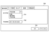
印刷ジョブ生成モジュール601は、図7の印刷設定画面700を用いてユーザが入力した各情報に基づいて印刷ジョブデータを生成する。印刷設定画面700では、例えば、ユーザがプルダウンメニュー701を用いて印刷ジョブデータの出力方法を設定する。プルダウンメニュー701には、通常印刷に対応する「印刷」及び留め置き印刷に対応する「留め置き」が表示され、また、予約印刷に対応する「予約印刷」も表示される。出力方法に予約印刷が設定された印刷ジョブデータ(以下、「予約印刷ジョブデータ」という。)(時刻設定印刷ジョブデータ)をPC12がMFP12に送信した場合、MFP12は受信した予約印刷ジョブデータを用いた印刷処理を即座に実行せず、上記予約印刷ジョブデータを記憶部304に一時的に格納する。MFP12は予約印刷ジョブデータに設定された予約時刻(指定時刻)に上記予約印刷ジョブデータを用いた印刷処理を実行する。予約時刻設定欄702には上記予約時刻が入力される。なお、予約時刻設定欄702に入力される予約時刻は絶対時刻又は現在時刻に対する相対時刻である。OKボタン403が選択されると、印刷ジョブ生成モジュール601は印刷設定画面700において設定された各情報に基づいて図8の印刷ジョブデータ801を生成する。
The print
印刷ジョブデータ801は印刷ジョブ名802、ユーザID803、出力方法804、予約時刻805、印刷設定806、及び印刷データ807を備える。印刷ジョブ名802は生成する印刷ジョブデータの名称である。ユーザID803は印刷設定画面700の設定を行ったユーザを特定するためのユーザIDである。出力方法804はプルダウンメニュー701を用いて設定された設定値である。予約時刻805は予約時刻設定欄702に入力された設定値である。印刷設定806は印刷設定画面700において設定された印刷部数、ステイプル設定、パンチ設定、給紙設定、解像度設定、及び印字色等の各設定値である。印刷データ807は印刷する文字や画像等を示すデータである。印刷ジョブ送信モジュール602は印刷ジョブ生成モジュール601によって生成された印刷ジョブデータ801をMFP12に送信する。
The
図9は、図1のMFP12のソフトウェアモジュール900の構成を概略的に示すブロック図である。
FIG. 9 is a block diagram schematically showing the configuration of the
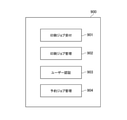
図9において、ソフトウェアモジュール900は、印刷ジョブ受付モジュール901、印刷ジョブ管理モジュール902、ユーザ認証モジュール903、及び予約ジョブ管理モジュール904を備える。ソフトウェアモジュール900の各処理はCPU301がROM303や記憶部304に格納されたプログラムを実行することによって行われる。
In FIG. 9, the
印刷ジョブ受付モジュール901はPC11等から受信した印刷ジョブデータ801を印刷ジョブ管理モジュール902に転送する。印刷ジョブ管理モジュール902はROM303や記憶部304に格納された図10の留め置きジョブリスト1001によって印刷ジョブデータを管理する。印刷ジョブ管理モジュール902には、受信した印刷ジョブデータのうち、記憶部304に格納された印刷ジョブデータに関する情報が登録される。留め置きジョブリスト1001は受信日時1002、ユーザID1003、印刷ジョブデータ名1004、出力方法1005、予約時刻1006、及び格納場所1007を備える。受信日時1002には上記格納された印刷ジョブデータをMFP12が受信した日時が設定される。ユーザID1003には上記格納された印刷ジョブデータの送信を指示したユーザを特定するユーザIDが設定される。印刷ジョブデータ名1004は上記格納された印刷ジョブデータのデータ名が設定される。出力方法1005には上記格納された印刷ジョブデータに含まれる出力方法、具体的に、「留め置き」及び「予約印刷」の何れかが設定される。予約時刻1006には上記格納された印刷ジョブデータに含まれる予約時刻が設定される。記憶部304に格納された印刷ジョブデータが予約時刻を含まない留め置き印刷ジョブデータである場合、予約時刻1006には「Null」が設定される。格納場所1007には上記格納された印刷ジョブデータの格納場所が設定される。
The print
ユーザ認証モジュール903はユーザが操作部307を用いて入力したユーザ情報に基づいてユーザ認証を行う。予約ジョブ管理モジュール904は印刷ジョブ管理モジュール902によって管理された複数の印刷ジョブデータのうち、予約印刷ジョブデータを管理する。
The
図11は、図1のMFP12によって実行されるジョブ管理処理の手順を示すフローチャートである。
FIG. 11 is a flowchart showing the procedure of the job management process executed by the
図11の処理は、CPU301がROM303や記憶部304に格納されたプログラムを実行することによって行われる。図11の処理は、モード設定画面400の設定がユーザによって予め行われ、また、一例として、PC11からMFP12へ印刷ジョブデータ801が送信されたことを前提とする。
The process of FIG. 11 is performed by the
図11において、まず、CPU301はPC11から印刷ジョブデータ801を受信すると(ステップS101)、印刷ジョブ管理モジュール902によって印刷ジョブデータ801を解析する。CPU301は印刷ジョブデータ801に設定された出力方法を確認する(ステップS102)。次いで、CPU301は記憶部304からモード設定値501を取得する(ステップS103)。次いで、CPU301は印刷ジョブデータ801に設定された出力方法が「予約印刷」であるか否かを判別する(ステップS104)。
In FIG. 11, first, when the
ステップS104の判別の結果、印刷ジョブデータ801に設定された出力方法が「予約印刷」であるとき、CPU301はMFP12の動作モードが強制留め置きモードであるか否かを判別する(ステップS105)。ステップS105では、ステップS103において取得したモード設定値501に強制留め置きモードが有効であることを示す「1」が設定されている場合、CPU301はMFP12の動作モードが強制留め置きモードであると判別する。一方、モード設定値501に通常印刷モードが無効であることを示す「0」が設定されている場合、CPU301はMFP12の動作モードが強制留め置きモードでないと判別する。
As a result of the determination in step S104, when the output method set in the
ステップS105の判別の結果、MFP12の動作モードが強制留め置きモードであるとき、CPU301は印刷ジョブデータ801を留め置き印刷ジョブデータとして管理する(ステップS106)。ステップS106では、CPU301は印刷ジョブデータ801を記憶部304に格納する。また、CPU301は印刷ジョブデータ801を留め置きジョブリスト1001に留め置き印刷ジョブデータとして登録する。具体的に、CPU301は印刷ジョブデータ801の情報として、留め置きジョブリスト1001の出力方法1005に「留め置き」を設定し、予約時刻1006に「Null」を設定する。その後、CPU301は本処理を終了する。MFP12は、印刷ジョブデータ801を留め置き印刷ジョブデータとして留め置きジョブリスト1001に登録した後、ユーザの操作部307による印刷指示を受け付けた際に印刷ジョブデータ801を用いた印刷処理を実行する。
As a result of the determination in step S105, when the operation mode of the
ステップS105の判別の結果、MFP12の動作モードが強制留め置きモードでないとき、CPU301は印刷ジョブデータ801を予約印刷ジョブデータとして管理する(ステップS107)。ステップS107では、CPU301は印刷ジョブデータ801を記憶部304に格納する。また、CPU301は印刷ジョブデータ801を留め置きジョブリスト1001に予約印刷ジョブデータとして登録する。具体的に、CPU301は印刷ジョブデータ801の情報として、留め置きジョブリスト1001の出力方法1005に「予約印刷」を設定し、予約時刻1006に予約印刷ジョブデータに含まれる予約時刻を設定する。その後、CPU301は本処理を終了する。MFP12は、印刷ジョブデータ801を予約印刷ジョブデータとして留め置きジョブリスト1001に登録した後、印刷ジョブデータ801に設定された予約時刻に印刷ジョブデータ801を用いた印刷処理を実行する。なお、本実施の形態では、ユーザは操作部307に表示される図12のジョブリスト画面1200から予約印刷ジョブデータとして登録された印刷ジョブデータの一覧情報を確認可能である。
As a result of the determination in step S105, when the operation mode of the
ステップS104の判別の結果、印刷ジョブデータ801に設定された出力方法が「予約印刷」でないとき、CPU301は印刷ジョブデータ801に設定された出力方法が「留め置き」及び「印刷」の何れであるかを判別する(ステップS108)。
As a result of the determination in step S104, when the output method set in the
ステップS108の判別の結果、印刷ジョブデータ801に設定された出力方法が「留め置き」であるとき、CPU301は印刷ジョブデータ801を留め置き印刷ジョブデータとして管理し(ステップS109)、本処理を終了する。
As a result of the determination in step S108, when the output method set in the
ステップS108の判別の結果、印刷ジョブデータ801に設定された出力方法が「印刷」であるとき、CPU301はMFP12の動作モードが強制留め置きモードであるか否かを判別する(ステップS110)。
As a result of the determination in step S108, when the output method set in the
ステップS110の判別の結果、MFP12の動作モードが強制留め置きモードであるとき、CPU301はステップS109の処理を行う。ステップS110の判別の結果、MFP12の動作モードが強制留め置きモードでないとき、CPU301は印刷ジョブデータ801を用いて印刷処理を行い(ステップS111)、本処理を終了する。
As a result of the determination in step S110, when the operation mode of the
ここで、例えば、図11の処理の後にユーザがモード設定画面400を用いて強制留め置きモードを無効から有効に切り替えた場合、強制留め置きモードが無効時に予約印刷ジョブデータとして登録された印刷ジョブデータ801に対してもMFP12は留め置き印刷を行う必要がある。ところが、従来のMFPでは、強制留め置きモードの設定に関わらず、印刷ジョブデータ801に設定された指定時刻に印刷ジョブデータ801の印刷を開始してしまう。すなわち、従来のMFPでは、強制留め置きモードが有効に設定される前に登録された印刷ジョブデータに対する強制留め置きモードが機能せず、印刷物が放置されるという問題が生じる。
Here, for example, when the user switches the forced retention mode from invalid to valid using the
これに対応して、本実施の形態では、格納された予約印刷ジョブデータを用いた印刷を行う前に強制留め置き印刷モードが無効から有効に切り替えられた場合、格納された予約印刷ジョブデータを削除する。 Corresponding to this, in the present embodiment, when the forced reservation printing mode is switched from invalid to enabled before printing using the stored reserved print job data, the stored reserved print job data is deleted. do.
図13は、図1のMFP12によって実行される予約印刷管理処理の手順を示すフローチャートである。
FIG. 13 is a flowchart showing a procedure of the reserved print management process executed by the
図13の処理も、CPU301がROM303や記憶部304に格納されたプログラムを実行することによって行われる。図13の処理は、ユーザがモード設定画面400を用いて強制留め置きモードを無効から有効に変更した際に実行される。
The process of FIG. 13 is also performed by the
図13において、CPU301はモード設定画面400において、ユーザがONボタン401を選択し、更にOKボタン403を選択したことを検知すると(ステップS201でYES)、留め置きジョブリスト1001に予約印刷ジョブデータが登録されているか否かを判別する(ステップS202)。
In FIG. 13, when the
ステップS202の判別の結果、留め置きジョブリスト1001に予約印刷ジョブデータが登録されていないとき、CPU301は本処理を終了する。ステップS202の判別の結果、留め置きジョブリスト1001に予約印刷ジョブデータが登録されているとき、CPU301は予約印刷ジョブデータの削除処理を行う(ステップS203)。具体的に、ステップS203では、CPU301は記憶部304に格納された全ての予約印刷ジョブデータを記憶部304から削除する。また、CPU301は登録された全ての予約印刷ジョブデータに関する情報、例えば、情報1008~1010を留め置きジョブリスト1001から削除する。その後、CPU301は本処理を終了する。なお、ステップS203の処理を行った後にユーザが操作部307に表示されたジョブリスト画面1200における更新ボタン1201を選択した場合、ジョブリスト画面1200のジョブ一覧1202には予約印刷ジョブデータが表示されない。
As a result of the determination in step S202, when the reserved print job data is not registered in the
上述した図13の処理によれば、格納された予約印刷ジョブデータを用いた印刷を行う前に強制留め置き印刷モードが無効から有効に切り替えられた場合、格納された予約印刷ジョブデータが削除される。これにより、留め置きジョブリスト1001に登録された予約印刷ジョブデータの印刷が指定時刻に開始されるのを防止することができ、もって、強制留め置きモードが機能しないことに起因する印刷物の放置を抑制することができる。
According to the process of FIG. 13 described above, if the forced reservation printing mode is switched from invalid to enabled before printing using the stored reserved print job data, the stored reserved print job data is deleted. .. As a result, it is possible to prevent printing of the reserved print job data registered in the
以上、本発明について、上述した実施の形態を用いて説明したが、本発明は上述した実施の形態に限定されるものではない。例えば、格納された予約印刷ジョブデータを用いた印刷処理を実行する前に強制留め置き印刷モードが無効から有効に切り替えられた場合、留め置きジョブリスト1001における予約印刷ジョブデータの情報を変更しても良い。
Although the present invention has been described above with reference to the above-described embodiment, the present invention is not limited to the above-mentioned embodiment. For example, if the forced reservation print mode is switched from invalid to enabled before executing the print process using the stored reserved print job data, the information of the reserved print job data in the
図14は、図13の予約印刷管理処理の変形例の手順を示すフローチャートである。 FIG. 14 is a flowchart showing a procedure of a modification of the reserved print management process of FIG.
図14の処理も、CPU301がROM303や記憶部304に格納されたプログラムを実行することによって行われ、ユーザがモード設定画面400を用いて強制留め置きモードを無効から有効に変更した際に実行される。
The process of FIG. 14 is also performed by the
図14において、まず、CPU301はステップS201及びS202の処理を行う。
In FIG. 14, first, the
ステップS202の判別の結果、留め置きジョブリスト1001に予約印刷ジョブデータが登録されていないとき、CPU301は本処理を終了する。ステップS202の判別の結果、留め置きジョブリスト1001に予約印刷ジョブデータが登録されているとき、CPU301は予約印刷ジョブデータの登録情報変更処理を行う(ステップS301)。具体的に、ステップS301では、CPU301は記憶部304に格納された全ての予約印刷ジョブデータを保持する。また、CPU301は留め置きジョブリスト1001において、登録された全ての予約印刷ジョブデータの出力方法1005を「予約印刷」から「留め置き」に変更し、また、予約時刻1006を「Null」に変更する。その後、CPU301は本処理を終了する。
As a result of the determination in step S202, when the reserved print job data is not registered in the
上述した図14の処理では、格納された予約印刷ジョブデータを用いた印刷を行う前に強制留め置き印刷モードが無効から有効に切り替えられた場合、留め置きジョブリスト1001における予約印刷ジョブデータの登録情報を留め置き印刷ジョブデータに相当する登録情報に変更する。これにより、留め置きジョブリスト1001に登録された予約印刷ジョブデータの印刷が指定時刻に開始されるのを防止することができ、もって、強制留め置きモードが機能しないことに起因する印刷物の放置を抑制することができる。
In the process of FIG. 14 described above, when the forced reservation print mode is switched from invalid to enabled before printing using the stored reserved print job data, the registration information of the reserved print job data in the
また、上述した実施の形態では、予約印刷ジョブデータが削除された旨、又は留め置きジョブリスト1001における予約印刷ジョブデータの登録情報が変更された旨を操作部307に通知しても良い。これにより、予約印刷ジョブデータの印刷が指定時刻に開始されないことをユーザに知らせることができる。
Further, in the above-described embodiment, the
本発明は、上述の実施の形態の1以上の機能を実現するプログラムをネットワーク又は記憶媒体を介してシステム又は装置に供給し、該システム又は装置のコンピュータにおける1つ以上のプロセッサがプログラムを読み出して実行する処理でも実現可能である。また、本発明は、1以上の機能を実現する回路(例えば、ASIC)によっても実現可能である。 The present invention supplies a program that realizes one or more functions of the above-described embodiment to a system or device via a network or storage medium, and one or more processors in the computer of the system or device read the program. It can also be realized by the processing to be executed. The present invention can also be realized by a circuit (for example, ASIC) that realizes one or more functions.
12 MFP
301 CPU
304 記憶部
307 操作部
400 モード設定画面
801 印刷ジョブデータ
1001 留め置きジョブリスト
12 MFP
301 CPU
304
Claims (10)
印刷ジョブを受信した際に前記印刷ジョブを前記記憶部に保存し、ユーザによる印刷指示に応じて前記印刷ジョブを実行する第1設定、及び、前記印刷ジョブを受信した際に前記印刷ジョブを前記記憶部に保存することなく前記印刷ジョブを実行する第2設定の何れかを設定する設定手段と、
情報処理装置から印刷ジョブを受信する受信手段と、
前記第2設定が設定されていて、かつ、前記受信した印刷ジョブが、印刷開始時刻が指定される予約印刷ジョブである場合、前記受信した印刷ジョブを前記記憶部に格納する格納手段と、
ユーザからの印刷指示なしに、前記格納された予約印刷ジョブを、前記指定される前記印刷開始時刻に実行する実行手段と、
前記格納された予約印刷ジョブの実行前に前記設定手段による設定が前記第2設定から前記第1設定に変更された場合、当該予約印刷ジョブを削除する削除手段と、を有することを特徴とする画像形成装置。 An image forming apparatus equipped with a storage unit.
The first setting for storing the print job in the storage unit when the print job is received and executing the print job in response to a print instruction by the user, and the print job when the print job is received. A setting means for setting any of the second settings for executing the print job without saving in the storage unit, and
A receiving means for receiving a print job from an information processing device,
When the second setting is set and the received print job is a reserved print job for which a print start time is specified, a storage means for storing the received print job in the storage unit and a storage means.
An execution means for executing the stored reserved print job at the designated print start time without a print instruction from the user.
It is characterized by having a deletion means for deleting the reserved print job when the setting by the setting means is changed from the second setting to the first setting before the execution of the stored reserved print job. Image forming device.
印刷ジョブを受信した際に前記印刷ジョブを前記記憶部に保存し、ユーザによる印刷指示に応じて前記印刷ジョブを実行する第1設定、及び、前記印刷ジョブを受信した際に前記印刷ジョブを前記記憶部に保存することなく前記印刷ジョブを実行する第2設定の何れかを設定する設定手段と、
情報処理装置から印刷ジョブを受信する受信手段と、
前記第2設定が設定されていて、かつ、前記受信した印刷ジョブが、印刷開始時刻が指定される予約印刷ジョブである場合、前記受信した印刷ジョブを前記記憶部に格納する格納手段と、
前記記憶部に格納された予約印刷ジョブの属性情報を管理する管理手段と、
ユーザからの印刷指示なしに、前記格納された予約印刷ジョブを、前記指定される前記印刷開始時刻に実行する実行手段と、を備え、
前記管理手段は、前記格納された予約印刷ジョブの実行前に前記設定手段による設定が前記第2設定から前記第1設定に変更された場合、当該予約印刷ジョブの属性情報を、ユーザによる印刷指示に応じて印刷を開始する旨を示す属性情報に変更することを特徴とする画像形成装置。 An image forming apparatus equipped with a storage unit.
The first setting for storing the print job in the storage unit when the print job is received and executing the print job in response to a print instruction by the user, and the print job when the print job is received. A setting means for setting any of the second settings for executing the print job without saving in the storage unit, and
A receiving means for receiving a print job from an information processing device,
When the second setting is set and the received print job is a reserved print job for which a print start time is specified, a storage means for storing the received print job in the storage unit and a storage means.
A management means for managing the attribute information of the reserved print job stored in the storage unit, and
An execution means for executing the stored reserved print job at the designated print start time without a print instruction from the user.
When the setting by the setting means is changed from the second setting to the first setting before the execution of the stored reserved print job, the management means prints the attribute information of the reserved print job by the user. An image forming apparatus characterized by changing to attribute information indicating that printing is started according to the above.
印刷ジョブを受信した際に前記印刷ジョブを前記記憶部に保存し、ユーザによる印刷指示に応じて前記印刷ジョブを実行する第1設定、及び、前記印刷ジョブを受信した際に前記印刷ジョブを前記記憶部に保存することなく前記印刷ジョブを実行する第2設定の何れかを設定する設定ステップと、
情報処理装置から印刷ジョブを受信する受信ステップと、
前記第2設定が設定されていて、かつ、前記受信した印刷ジョブが、印刷開始時刻が指定される予約印刷ジョブである場合、前記受信した印刷ジョブを前記記憶部に格納する格納ステップと、
ユーザからの印刷指示なしに、前記格納された予約印刷ジョブを、前記指定される前記印刷開始時刻に実行する実行ステップと、
前記格納された予約印刷ジョブの実行前に前記設定ステップにおける設定が前記第2設定から前記第1設定に変更された場合、当該予約印刷ジョブを削除する削除ステップと、を有することを特徴とする画像形成装置の制御方法。 It is a control method of an image forming apparatus provided with a storage unit.
The first setting for storing the print job in the storage unit when the print job is received and executing the print job in response to a print instruction by the user, and the print job when the print job is received. A setting step for setting one of the second settings for executing the print job without saving in the storage unit, and
A reception step for receiving a print job from an information processing device, and
When the second setting is set and the received print job is a reserved print job for which a print start time is specified, a storage step for storing the received print job in the storage unit and a storage step.
An execution step of executing the stored reserved print job at the specified print start time without a print instruction from the user, and
It is characterized by having a deletion step of deleting the reserved print job when the setting in the setting step is changed from the second setting to the first setting before the execution of the stored reserved print job. A control method for an image forming apparatus.
印刷ジョブを受信した際に前記印刷ジョブを前記記憶部に保存し、ユーザによる印刷指示に応じて前記印刷ジョブを実行する第1設定、及び、前記印刷ジョブを受信した際に前記印刷ジョブを前記記憶部に保存することなく前記印刷ジョブを実行する第2設定の何れかを設定する設定ステップと、
情報処理装置から印刷ジョブを受信する受信ステップと、
前記第2設定が設定されていて、かつ、前記受信した印刷ジョブが、印刷開始時刻が指定される予約印刷ジョブである場合、前記受信した印刷ジョブを前記記憶部に格納する格納ステップと、
前記記憶部に格納された予約印刷ジョブの属性情報を管理する管理ステップと、
ユーザからの印刷指示なしに、前記格納された予約印刷ジョブを、前記指定される前記印刷開始時刻に実行する実行ステップと、を有し、
前記管理ステップは、前記格納された予約印刷ジョブの実行前に前記設定ステップにおける設定が前記第2設定から前記第1設定に変更された場合、当該予約印刷ジョブの属性情報を、ユーザによる印刷指示に応じて印刷を開始する旨を示す属性情報に変更することを特徴とする画像形成装置の制御方法。 It is a control method of an image forming apparatus provided with a storage unit.
The first setting for storing the print job in the storage unit when the print job is received and executing the print job in response to a print instruction by the user, and the print job when the print job is received. A setting step for setting one of the second settings for executing the print job without saving in the storage unit, and
A reception step for receiving a print job from an information processing device, and
When the second setting is set and the received print job is a reserved print job for which a print start time is specified, a storage step for storing the received print job in the storage unit and a storage step.
A management step for managing the attribute information of the reserved print job stored in the storage unit, and
It has an execution step of executing the stored reserved print job at the designated print start time without a print instruction from the user.
In the management step, when the setting in the setting step is changed from the second setting to the first setting before the execution of the stored reserved print job, the attribute information of the reserved print job is printed by the user. A control method for an image forming apparatus, which comprises changing to attribute information indicating that printing is started according to the above.
前記画像形成装置の制御方法は、
印刷ジョブを受信した際に前記印刷ジョブを前記記憶部に保存し、ユーザによる印刷指示に応じて前記印刷ジョブを実行する第1設定、及び、前記印刷ジョブを受信した際に前記印刷ジョブを前記記憶部に保存することなく前記印刷ジョブを実行する第2設定の何れかを設定する設定ステップと、
情報処理装置から印刷ジョブを受信する受信ステップと、
前記第2設定が設定されていて、かつ、前記受信した印刷ジョブが、印刷開始時刻が指定される予約印刷ジョブである場合、前記受信した印刷ジョブを前記記憶部に格納する格納ステップと、
ユーザからの印刷指示なしに、前記格納された予約印刷ジョブを、前記指定される前記印刷開始時刻に実行する実行ステップと、
前記格納された予約印刷ジョブの実行前に前記設定ステップにおける設定が前記第2設定から前記第1設定に変更された場合、当該予約印刷ジョブを削除する削除ステップと、を有することを特徴とするプログラム。 A program that causes a computer to execute a control method for an image forming apparatus equipped with a storage unit.
The control method of the image forming apparatus is
The first setting for storing the print job in the storage unit when the print job is received and executing the print job in response to a print instruction by the user, and the print job when the print job is received. A setting step for setting one of the second settings for executing the print job without saving in the storage unit, and
A reception step for receiving a print job from an information processing device, and
When the second setting is set and the received print job is a reserved print job for which a print start time is specified, a storage step for storing the received print job in the storage unit and a storage step.
An execution step of executing the stored reserved print job at the specified print start time without a print instruction from the user, and
It is characterized by having a deletion step of deleting the reserved print job when the setting in the setting step is changed from the second setting to the first setting before the execution of the stored reserved print job. program.
前記画像形成装置の制御方法は、
印刷ジョブを受信した際に前記印刷ジョブを前記記憶部に保存し、ユーザによる印刷指示に応じて前記印刷ジョブを実行する第1設定、及び、前記印刷ジョブを受信した際に前記印刷ジョブを前記記憶部に保存することなく前記印刷ジョブを実行する第2設定の何れかを設定する設定ステップと、
情報処理装置から印刷ジョブを受信する受信ステップと、
前記第2設定が設定されていて、かつ、前記受信した印刷ジョブが、印刷開始時刻が指定される予約印刷ジョブである場合、前記受信した印刷ジョブを前記記憶部に格納する格納ステップと、
前記記憶部に格納された予約印刷ジョブの属性情報を管理する管理ステップと、
ユーザからの印刷指示なしに、前記格納された予約印刷ジョブを、前記指定される前記印刷開始時刻に実行する実行ステップと、を有し、
前記管理ステップは、前記格納された予約印刷ジョブの実行前に前記設定ステップにおける設定が前記第2設定から前記第1設定に変更された場合、当該予約印刷ジョブの属性情報を、ユーザによる印刷指示に応じて印刷を開始する旨を示す属性情報に変更することを特徴とするプログラム。 A program that causes a computer to execute a control method for an image forming apparatus equipped with a storage unit.
The control method of the image forming apparatus is
The first setting for storing the print job in the storage unit when the print job is received and executing the print job in response to a print instruction by the user, and the print job when the print job is received. A setting step for setting one of the second settings for executing the print job without saving in the storage unit, and
A reception step for receiving a print job from an information processing device, and
When the second setting is set and the received print job is a reserved print job for which a print start time is specified, a storage step for storing the received print job in the storage unit and a storage step.
A management step for managing the attribute information of the reserved print job stored in the storage unit, and
It has an execution step of executing the stored reserved print job at the designated print start time without a print instruction from the user.
In the management step, when the setting in the setting step is changed from the second setting to the first setting before the execution of the stored reserved print job, the attribute information of the reserved print job is printed by the user. A program characterized by changing to attribute information indicating that printing is started according to the above.
Priority Applications (2)
| Application Number | Priority Date | Filing Date | Title |
|---|---|---|---|
| JP2017188363A JP6998714B2 (en) | 2017-09-28 | 2017-09-28 | Image forming device and its control method, and program |
| US16/129,105 US10768872B2 (en) | 2017-09-28 | 2018-09-12 | Image forming apparatus performing hold printing, control method therefor, and storage medium storing control program therefor |
Applications Claiming Priority (1)
| Application Number | Priority Date | Filing Date | Title |
|---|---|---|---|
| JP2017188363A JP6998714B2 (en) | 2017-09-28 | 2017-09-28 | Image forming device and its control method, and program |
Publications (3)
| Publication Number | Publication Date |
|---|---|
| JP2019064003A JP2019064003A (en) | 2019-04-25 |
| JP2019064003A5 JP2019064003A5 (en) | 2020-11-12 |
| JP6998714B2 true JP6998714B2 (en) | 2022-01-18 |
Family
ID=65808868
Family Applications (1)
| Application Number | Title | Priority Date | Filing Date |
|---|---|---|---|
| JP2017188363A Active JP6998714B2 (en) | 2017-09-28 | 2017-09-28 | Image forming device and its control method, and program |
Country Status (2)
| Country | Link |
|---|---|
| US (1) | US10768872B2 (en) |
| JP (1) | JP6998714B2 (en) |
Families Citing this family (5)
| Publication number | Priority date | Publication date | Assignee | Title |
|---|---|---|---|---|
| JP7039235B2 (en) * | 2017-09-29 | 2022-03-22 | キヤノン株式会社 | Printing device, control method of printing device, and program |
| JP2019098576A (en) * | 2017-11-30 | 2019-06-24 | コニカミノルタ株式会社 | Image forming apparatus |
| JP7306108B2 (en) * | 2019-06-26 | 2023-07-11 | 京セラドキュメントソリューションズ株式会社 | Image forming apparatus and image forming method |
| JP2021157444A (en) * | 2020-03-26 | 2021-10-07 | キヤノン株式会社 | Image forming apparatus, printing system, control method, and program |
| JP2024024710A (en) * | 2022-08-10 | 2024-02-26 | キヤノン株式会社 | Printing device, control method, and its program |
Citations (18)
| Publication number | Priority date | Publication date | Assignee | Title |
|---|---|---|---|---|
| JP2000347818A (en) | 1999-06-02 | 2000-12-15 | Canon Inc | Printing method with automatic saving function for print data and medium where module implemented by same method is recorded |
| JP2000351254A (en) | 1999-06-10 | 2000-12-19 | Canon Inc | Print controller, printer, print control method, and memory medium |
| JP2001236184A (en) | 2000-02-22 | 2001-08-31 | Canon Inc | Device and method for outputting image and storage medium |
| JP2002240398A (en) | 2001-02-15 | 2002-08-28 | Ricoh Co Ltd | Printer and its controlling method |
| JP2008186407A (en) | 2007-01-31 | 2008-08-14 | Brother Ind Ltd | Image forming system, image forming device, and computer |
| US20100007909A1 (en) | 2008-07-08 | 2010-01-14 | Xerox Corporation | Method and apparatus for deleting secure print jobs |
| JP2013107361A (en) | 2011-11-24 | 2013-06-06 | Canon Inc | Printing apparatus, method of controlling the same, and control program |
| JP2013168900A (en) | 2012-02-17 | 2013-08-29 | Canon Inc | Image forming apparatus and control method of image forming apparatus, and program |
| JP2014032456A (en) | 2012-08-01 | 2014-02-20 | Oki Data Corp | Image forming system |
| JP2014065146A (en) | 2012-09-24 | 2014-04-17 | Oki Data Corp | Image formation device and data processing program |
| JP2014223754A (en) | 2013-05-16 | 2014-12-04 | キヤノン株式会社 | Printer, control method of the printer, and program |
| JP2014237305A (en) | 2013-05-07 | 2014-12-18 | キヤノン株式会社 | Image formation apparatus, information processing apparatus, printing system, and control method therefor, and program |
| JP2015160379A (en) | 2014-02-27 | 2015-09-07 | ブラザー工業株式会社 | image forming apparatus |
| JP2016175187A (en) | 2015-03-18 | 2016-10-06 | キヤノン株式会社 | Image forming apparatus and method for controlling the same, information processing device and method for controlling the same, and program |
| JP2015104867A5 (en) | 2013-11-29 | 2016-11-17 | ||
| JP2017004175A (en) | 2015-06-08 | 2017-01-05 | キヤノン株式会社 | Management system and control method thereof, information processing device, and program |
| JP2017019195A (en) | 2015-07-10 | 2017-01-26 | キヤノン株式会社 | Printing device and control method of the same |
| JP2017113908A (en) | 2015-12-22 | 2017-06-29 | キヤノン株式会社 | Printer |
Family Cites Families (6)
| Publication number | Priority date | Publication date | Assignee | Title |
|---|---|---|---|---|
| JP4508234B2 (en) * | 2007-12-13 | 2010-07-21 | コニカミノルタビジネステクノロジーズ株式会社 | Image forming apparatus and image forming program |
| JP4770949B2 (en) * | 2009-03-06 | 2011-09-14 | コニカミノルタビジネステクノロジーズ株式会社 | Image forming system, information processing apparatus, print server, image forming apparatus, image forming auxiliary program, and printing control method |
| JP6395374B2 (en) * | 2013-11-29 | 2018-09-26 | キヤノン株式会社 | Image forming apparatus, image forming apparatus control method, and computer-readable program |
| JP6406030B2 (en) * | 2015-01-26 | 2018-10-17 | ブラザー工業株式会社 | Printing device, printing job management method for printing device, and program |
| JP6819157B2 (en) * | 2016-09-07 | 2021-01-27 | 富士ゼロックス株式会社 | Information processing equipment and programs |
| JP2018140590A (en) * | 2017-02-28 | 2018-09-13 | コニカミノルタ株式会社 | Image forming device, control method of image forming device, and control program of image forming device |
-
2017
- 2017-09-28 JP JP2017188363A patent/JP6998714B2/en active Active
-
2018
- 2018-09-12 US US16/129,105 patent/US10768872B2/en active Active
Patent Citations (18)
| Publication number | Priority date | Publication date | Assignee | Title |
|---|---|---|---|---|
| JP2000347818A (en) | 1999-06-02 | 2000-12-15 | Canon Inc | Printing method with automatic saving function for print data and medium where module implemented by same method is recorded |
| JP2000351254A (en) | 1999-06-10 | 2000-12-19 | Canon Inc | Print controller, printer, print control method, and memory medium |
| JP2001236184A (en) | 2000-02-22 | 2001-08-31 | Canon Inc | Device and method for outputting image and storage medium |
| JP2002240398A (en) | 2001-02-15 | 2002-08-28 | Ricoh Co Ltd | Printer and its controlling method |
| JP2008186407A (en) | 2007-01-31 | 2008-08-14 | Brother Ind Ltd | Image forming system, image forming device, and computer |
| US20100007909A1 (en) | 2008-07-08 | 2010-01-14 | Xerox Corporation | Method and apparatus for deleting secure print jobs |
| JP2013107361A (en) | 2011-11-24 | 2013-06-06 | Canon Inc | Printing apparatus, method of controlling the same, and control program |
| JP2013168900A (en) | 2012-02-17 | 2013-08-29 | Canon Inc | Image forming apparatus and control method of image forming apparatus, and program |
| JP2014032456A (en) | 2012-08-01 | 2014-02-20 | Oki Data Corp | Image forming system |
| JP2014065146A (en) | 2012-09-24 | 2014-04-17 | Oki Data Corp | Image formation device and data processing program |
| JP2014237305A (en) | 2013-05-07 | 2014-12-18 | キヤノン株式会社 | Image formation apparatus, information processing apparatus, printing system, and control method therefor, and program |
| JP2014223754A (en) | 2013-05-16 | 2014-12-04 | キヤノン株式会社 | Printer, control method of the printer, and program |
| JP2015104867A5 (en) | 2013-11-29 | 2016-11-17 | ||
| JP2015160379A (en) | 2014-02-27 | 2015-09-07 | ブラザー工業株式会社 | image forming apparatus |
| JP2016175187A (en) | 2015-03-18 | 2016-10-06 | キヤノン株式会社 | Image forming apparatus and method for controlling the same, information processing device and method for controlling the same, and program |
| JP2017004175A (en) | 2015-06-08 | 2017-01-05 | キヤノン株式会社 | Management system and control method thereof, information processing device, and program |
| JP2017019195A (en) | 2015-07-10 | 2017-01-26 | キヤノン株式会社 | Printing device and control method of the same |
| JP2017113908A (en) | 2015-12-22 | 2017-06-29 | キヤノン株式会社 | Printer |
Also Published As
| Publication number | Publication date |
|---|---|
| US20190095152A1 (en) | 2019-03-28 |
| JP2019064003A (en) | 2019-04-25 |
| US10768872B2 (en) | 2020-09-08 |
Similar Documents
| Publication | Publication Date | Title |
|---|---|---|
| JP6998714B2 (en) | Image forming device and its control method, and program | |
| US10168967B2 (en) | Image forming apparatus, information processing method, and storage medium | |
| US8493594B2 (en) | Image processing apparatus, method, and program for performing interruption printing | |
| US8593663B2 (en) | Image forming apparatus for storing and processing electronic documents and image data, data processing method, and storage medium thereof | |
| JP6257170B2 (en) | Image forming system, image forming apparatus, and control method thereof | |
| JP4949980B2 (en) | Image forming apparatus, image forming method, image forming program, and image forming system | |
| US10664212B2 (en) | Image forming apparatus, control method for image forming apparatus, and storage medium for controlling storage of a print job | |
| JP2009029136A (en) | Printing apparatus, printing method, and printing system | |
| US8248633B2 (en) | Image forming apparatus and method for switching between security modes | |
| KR20130031208A (en) | Printing control apparatus and control method therefor | |
| JP2014237305A (en) | Image formation apparatus, information processing apparatus, printing system, and control method therefor, and program | |
| JP2020093549A (en) | Printing apparatus, control method therefor, and program | |
| JP6529376B2 (en) | PRINTING APPARATUS, ITS CONTROL METHOD, AND PROGRAM | |
| US20130155452A1 (en) | Image forming apparatus and image forming method involving reuse function | |
| JP7039235B2 (en) | Printing device, control method of printing device, and program | |
| US11388298B2 (en) | Image forming apparatus and control method therefor | |
| JP2010228198A (en) | Image forming apparatus, alternative image forming apparatus, printing system, and printing method | |
| JP6552281B2 (en) | INFORMATION PROCESSING APPARATUS, CONTROL METHOD FOR INFORMATION PROCESSING APPARATUS, AND PROGRAM | |
| US10740055B2 (en) | Print system, print apparatus, and storage medium | |
| JP2018020443A (en) | Image formation apparatus, printing method and computer program | |
| JP5686063B2 (en) | Network system, image forming apparatus, and program | |
| US11262961B2 (en) | Printing system and control method for performing user authentication | |
| JP2005292908A (en) | System, program and method for service providing, and job management system | |
| US11409485B2 (en) | Printing system and control method that maintains a response performance when processing load increases | |
| JP2008195041A (en) | Image formation system, information processing method, information processing program |
Legal Events
| Date | Code | Title | Description |
|---|---|---|---|
| A521 | Request for written amendment filed |
Free format text: JAPANESE INTERMEDIATE CODE: A523 Effective date: 20200925 |
|
| A621 | Written request for application examination |
Free format text: JAPANESE INTERMEDIATE CODE: A621 Effective date: 20200925 |
|
| A977 | Report on retrieval |
Free format text: JAPANESE INTERMEDIATE CODE: A971007 Effective date: 20210720 |
|
| A131 | Notification of reasons for refusal |
Free format text: JAPANESE INTERMEDIATE CODE: A131 Effective date: 20210817 |
|
| A521 | Request for written amendment filed |
Free format text: JAPANESE INTERMEDIATE CODE: A523 Effective date: 20211014 |
|
| TRDD | Decision of grant or rejection written | ||
| A01 | Written decision to grant a patent or to grant a registration (utility model) |
Free format text: JAPANESE INTERMEDIATE CODE: A01 Effective date: 20211122 |
|
| A61 | First payment of annual fees (during grant procedure) |
Free format text: JAPANESE INTERMEDIATE CODE: A61 Effective date: 20211221 |
|
| R151 | Written notification of patent or utility model registration |
Ref document number: 6998714 Country of ref document: JP Free format text: JAPANESE INTERMEDIATE CODE: R151 |