JP6997076B2 - Simultaneous beam formation training for methods, equipment and systems for channel estimation and multi-input multi-output (MIMO) communication. - Google Patents
Simultaneous beam formation training for methods, equipment and systems for channel estimation and multi-input multi-output (MIMO) communication. Download PDFInfo
- Publication number
- JP6997076B2 JP6997076B2 JP2018513338A JP2018513338A JP6997076B2 JP 6997076 B2 JP6997076 B2 JP 6997076B2 JP 2018513338 A JP2018513338 A JP 2018513338A JP 2018513338 A JP2018513338 A JP 2018513338A JP 6997076 B2 JP6997076 B2 JP 6997076B2
- Authority
- JP
- Japan
- Prior art keywords
- channel estimation
- channel
- wtru
- estimation signal
- complex numbers
- Prior art date
- Legal status (The legal status is an assumption and is not a legal conclusion. Google has not performed a legal analysis and makes no representation as to the accuracy of the status listed.)
- Active
Links
Images


Classifications
-
- H—ELECTRICITY
- H04—ELECTRIC COMMUNICATION TECHNIQUE
- H04L—TRANSMISSION OF DIGITAL INFORMATION, e.g. TELEGRAPHIC COMMUNICATION
- H04L27/00—Modulated-carrier systems
- H04L27/26—Systems using multi-frequency codes
- H04L27/2601—Multicarrier modulation systems
- H04L27/2602—Signal structure
- H04L27/261—Details of reference signals
- H04L27/2613—Structure of the reference signals
-
- H—ELECTRICITY
- H04—ELECTRIC COMMUNICATION TECHNIQUE
- H04B—TRANSMISSION
- H04B7/00—Radio transmission systems, i.e. using radiation field
- H04B7/02—Diversity systems; Multi-antenna system, i.e. transmission or reception using multiple antennas
- H04B7/04—Diversity systems; Multi-antenna system, i.e. transmission or reception using multiple antennas using two or more spaced independent antennas
- H04B7/0413—MIMO systems
- H04B7/0452—Multi-user MIMO systems
-
- H—ELECTRICITY
- H04—ELECTRIC COMMUNICATION TECHNIQUE
- H04B—TRANSMISSION
- H04B7/00—Radio transmission systems, i.e. using radiation field
- H04B7/02—Diversity systems; Multi-antenna system, i.e. transmission or reception using multiple antennas
- H04B7/04—Diversity systems; Multi-antenna system, i.e. transmission or reception using multiple antennas using two or more spaced independent antennas
- H04B7/06—Diversity systems; Multi-antenna system, i.e. transmission or reception using multiple antennas using two or more spaced independent antennas at the transmitting station
- H04B7/0613—Diversity systems; Multi-antenna system, i.e. transmission or reception using multiple antennas using two or more spaced independent antennas at the transmitting station using simultaneous transmission
- H04B7/0615—Diversity systems; Multi-antenna system, i.e. transmission or reception using multiple antennas using two or more spaced independent antennas at the transmitting station using simultaneous transmission of weighted versions of same signal
- H04B7/0617—Diversity systems; Multi-antenna system, i.e. transmission or reception using multiple antennas using two or more spaced independent antennas at the transmitting station using simultaneous transmission of weighted versions of same signal for beam forming
-
- H—ELECTRICITY
- H04—ELECTRIC COMMUNICATION TECHNIQUE
- H04B—TRANSMISSION
- H04B7/00—Radio transmission systems, i.e. using radiation field
- H04B7/02—Diversity systems; Multi-antenna system, i.e. transmission or reception using multiple antennas
- H04B7/04—Diversity systems; Multi-antenna system, i.e. transmission or reception using multiple antennas using two or more spaced independent antennas
- H04B7/06—Diversity systems; Multi-antenna system, i.e. transmission or reception using multiple antennas using two or more spaced independent antennas at the transmitting station
- H04B7/0613—Diversity systems; Multi-antenna system, i.e. transmission or reception using multiple antennas using two or more spaced independent antennas at the transmitting station using simultaneous transmission
- H04B7/0615—Diversity systems; Multi-antenna system, i.e. transmission or reception using multiple antennas using two or more spaced independent antennas at the transmitting station using simultaneous transmission of weighted versions of same signal
- H04B7/0619—Diversity systems; Multi-antenna system, i.e. transmission or reception using multiple antennas using two or more spaced independent antennas at the transmitting station using simultaneous transmission of weighted versions of same signal using feedback from receiving side
- H04B7/0621—Feedback content
- H04B7/0626—Channel coefficients, e.g. channel state information [CSI]
-
- H—ELECTRICITY
- H04—ELECTRIC COMMUNICATION TECHNIQUE
- H04L—TRANSMISSION OF DIGITAL INFORMATION, e.g. TELEGRAPHIC COMMUNICATION
- H04L25/00—Baseband systems
- H04L25/02—Details ; arrangements for supplying electrical power along data transmission lines
- H04L25/0202—Channel estimation
- H04L25/0204—Channel estimation of multiple channels
-
- H—ELECTRICITY
- H04—ELECTRIC COMMUNICATION TECHNIQUE
- H04L—TRANSMISSION OF DIGITAL INFORMATION, e.g. TELEGRAPHIC COMMUNICATION
- H04L25/00—Baseband systems
- H04L25/02—Details ; arrangements for supplying electrical power along data transmission lines
- H04L25/0202—Channel estimation
- H04L25/024—Channel estimation channel estimation algorithms
-
- H—ELECTRICITY
- H04—ELECTRIC COMMUNICATION TECHNIQUE
- H04L—TRANSMISSION OF DIGITAL INFORMATION, e.g. TELEGRAPHIC COMMUNICATION
- H04L5/00—Arrangements affording multiple use of the transmission path
- H04L5/0001—Arrangements for dividing the transmission path
- H04L5/0014—Three-dimensional division
- H04L5/0023—Time-frequency-space
-
- H—ELECTRICITY
- H04—ELECTRIC COMMUNICATION TECHNIQUE
- H04L—TRANSMISSION OF DIGITAL INFORMATION, e.g. TELEGRAPHIC COMMUNICATION
- H04L5/00—Arrangements affording multiple use of the transmission path
- H04L5/003—Arrangements for allocating sub-channels of the transmission path
- H04L5/0053—Allocation of signaling, i.e. of overhead other than pilot signals
Description
本発明はワイヤレス通信の分野に関し、より詳細には、チャネル推定を実行するための方法、装置およびシステムならびにMIMO通信のための同時のビーム形成トレーニングに関するものである。 The present invention relates to the field of wireless communication, and more particularly to methods, devices and systems for performing channel estimation and simultaneous beam forming training for MIMO communication.
関連出願の相互参照
本出願は、どちらも参照により本明細書に組み込まれている、2015年9月10日に出願された、名称「Methods, Apparatus and Systems for Channel Estimation and Simultaneous Beamforming Training for Multi-input Multi-output (MIMO) Communications」の米国特許仮出願第62/216,604号と、2016年7月21日に出願された、名称「Methods, Apparatus and Systems for Channel Estimation and Simultaneous Beamforming Training for Multi-input Multi-output (MIMO) Communications」の米国特許仮出願第62/365,043号との優先権を主張するものである。
Mutual Reference of Related Applications This application, both of which are incorporated herein by reference, is filed on September 10, 2015, with the name "Methods, Apparatus and Systems for Channel Estimation and Simultaneous Beamforming". US Patent Application No. 62 / 216,604 of "input Multi-output (MIMO) Communications" and the name "Methods, Aperatus and Systems for Beamforming Manual Beamforming" filed on July 21, 2016. -It claims priority with US Patent Provisional Application No. 62 / 365,043 of "input Multi-output (MIMO) Communications".
ワイヤレスローカルエリアネットワーク(WLAN)はワイヤレス通信サービスを提供することができる。WLANは、たとえばインフラストラクチャモードおよびアドホックモードといった複数のモードを有することができる。アドホックモードでは、1つまたは複数のSTAがピアツーピア(P2P)で直接送信する。インフラストラクチャモードでは、1つまたは複数の局(STA)が、他のネットワーク(インターネットまたはローカルエリアネットワークなど)に対するブリッジとして働くアクセスポイント(AP)を介して通信する。インフラストラクチャモードで動作するWLANは、マルチユーザMIMO(MU-MIMO)などのMIMO通信を提供することができる。 A wireless local area network (WLAN) can provide wireless communication services. The WLAN can have multiple modes, for example infrastructure mode and ad hoc mode. In ad hoc mode, one or more STAs transmit directly peer-to-peer (P2P). In infrastructure mode, one or more stations (STAs) communicate over an access point (AP) that acts as a bridge to other networks (such as the Internet or local area networks). A WLAN operating in infrastructure mode can provide MIMO communication such as multi-user MIMO (MU-MIMO).
マルチチャネルをサポートするWLANシステム、ならびに802.11n、802.11ac、802.11af、および802.11ahなどのチャネル幅は、プライマリチャネルとして指定されるチャネルを含む。スペクトル効率を改善するために、802.11acは、たとえばダウンリンク直交周波数分割多重(OFDM)シンボル中に、同一シンボルの時間フレームにおける複数のSTAへのダウンリンクMU-MIMO送信のための概念を導入している。802.11ahについては、ダウンリンクMU-MIMOの使用の可能性も考えられている。ダウンリンクMU-MIMOが、複数のSTAに対する波形送信の複数のSTA干渉に対して同一のシンボルタイミングを使用することに留意することが重要である。APを用いるMU-MIMO送信に包含されるすべてのSTAは、同一のチャネルまたは帯域を使用することができる。これは、動作帯域幅を、APを用いるMU-MIMO送信に含まれるSTAによってサポートされる最も小さいチャネル帯域幅に制限する。そのような制限を解決するために、本出願は、チャネル推定のための方法、装置、およびシステムならびにMIMO通信のための同時のビーム形成トレーニングを提案するものである。 WLAN systems that support multi-channel, as well as channel widths such as 802.11n, 802.11ac, 802.11af, and 802.11ah, include channels designated as primary channels. To improve spectral efficiency, 802.11ac introduced the concept for downlink MU-MIMO transmission to multiple STAs in a time frame of the same symbol, for example in a downlink orthogonal frequency division multiplexing (OFDM) symbol. is doing. For 802.11ah, the possibility of using downlink MU-MIMO is also considered. It is important to note that downlink MU-MIMO uses the same symbol timing for multiple STA interferences of waveform transmission to multiple STAs. All STAs included in MU-MIMO transmission using AP can use the same channel or band. This limits the operating bandwidth to the smallest channel bandwidth supported by the STA included in MU-MIMO transmission with AP. To resolve such limitations, the present application proposes methods, devices, and systems for channel estimation and simultaneous beam formation training for MIMO communication.
MIMO通信のための複数のチャネルのチャネル推定を可能にするための方法、装置およびシステム。ワイヤレスネットワークにおける同時のビーム形成トレーニングを実行するための方法、装置、およびシステムも提供される。 Methods, devices and systems for enabling channel estimation of multiple channels for MIMO communication. Methods, devices, and systems for performing simultaneous beam formation training in wireless networks are also provided.
電子デバイスが、ワイヤレスネットワークにおけるMIMO通信用の複数のチャネルに関するチャネル推定のための情報を送信するための代表的な方法は、第1のチャネルに関連した第1のチャネル推定信号を備える複素数の第1のセットを決定するステップと、第2のチャネルに関連した第2のチャネル推定信号を備える複素数の第2のセットを決定するステップと、物理レイヤ(PHY)フレームによって複素数の第1のセットおよび複素数の第2のセットを送信するステップとを含み、複素数の第2のセットは複素数の第1のセットの共役複素数である。 A typical method for an electronic device to transmit information for channel estimation about a plurality of channels for MIMO communication in a wireless network is a complex number with a first channel estimation signal associated with the first channel. The step of determining one set, the step of determining the second set of complex numbers with the second channel estimation signal associated with the second channel, and the first set of complex numbers by the physical layer (PHY) frame and The second set of complex numbers is the conjugate complex number of the first set of complex numbers, including the step of transmitting a second set of complex numbers.
電子デバイスが、ワイヤレスネットワークにおけるMIMO通信用の複数のチャネルのチャネル推定を実行するための代表的な方法は、第1のチャネル推定信号を備える複素数の第1のセットおよび第2のチャネル推定信号を備える複素数の第2のセットを受信するステップと、第1のチャネル推定信号に基づいて第1のチャネルを決定し、第2のチャネル推定信号に基づいて第2のチャネルを決定するステップとを含み、複素数の第1のセットおよび複素数の第2のセットはPHYフレームによって受信され、複素数の第2のセットは複素数の第1のセットの共役複素数である。 A typical method for an electronic device to perform channel estimation of multiple channels for MIMO communication in a wireless network is to use a first set of complex numbers with a first channel estimation signal and a second channel estimation signal. Includes a step of receiving a second set of complex numbers to include, a step of determining the first channel based on the first channel estimation signal, and a step of determining the second channel based on the second channel estimation signal. , The first set of complex numbers and the second set of complex numbers are received by the PHY frame, the second set of complex numbers is the conjugate complex number of the first set of complex numbers.
電子デバイスが、ワイヤレスネットワークにおけるMIMO通信用のビーム形成を送信するための代表的な方法は、セクタレベルスイープ(SLS)およびビームリファインメント(Beam Refinement)プロトコル(BRP)を実行して、1つまたは複数の局(STA)のすべてのためのビームを識別するステップと、隣接したビームに配設された第1のSTAおよび第2のSTAを識別するステップと、第1のチャネルに対応する第1のストリームの情報および第2のチャネルに対応する第2のストリームの情報を含むPHYフレームを使用して、第1のSTAおよび第2のSTAへマルチユーザ送信を送信するステップと、第1のSTAおよび第2のSTAへ、ユーザ固有の情報を、PHYフレームにおいて同時に送信するステップとを含み、PHYフレームは、第1のストリームと第2のストリームの両方に、レガシーショートトレーニングフィールド(STF)、ロングトレーニングフィールド(LTF)、および信号(SIG)を含み、PHYフレームは、1つまたは複数のSTAの情報と、第1のストリームを第1のSTAに関連付けるとともに第2のストリームを第2のSTAに関連付ける情報とを含んでいる共通ヘッダを含む。 A typical method for an electronic device to transmit a beam formation for MIMO communication in a wireless network is to perform a sector level sweep (SLS) and a beam refinement protocol (BRP), one or the other. A step of identifying beams for all of the plurality of stations (STAs), a step of identifying first and second STAs arranged in adjacent beams, and a first corresponding to the first channel. A step of transmitting a multi-user transmission to the first STA and the second STA using a PHY frame containing the information of the stream and the information of the second stream corresponding to the second channel, and the first STA. And to the second STA, including the step of simultaneously transmitting user-specific information in the PHY frame, the PHY frame has a Legacy Short Training Field (STF), long in both the first and second streams. Includes training fields (LTF), and signals (SIG), and the PHY frame associates the information of one or more STAs with the first stream to the first STA and the second stream to the second STA. Contains a common header that contains the associated information.
代表的な装置は、ワイヤレスネットワークにおけるMIMO通信用の複数のチャネルに関するチャネル推定のための情報を送信するように構成された電子デバイスを含む。この電子デバイスは、(1)第1のチャネルに関連した第1のチャネル推定信号を備える複素数の第1のセットを決定し、(2)第2のチャネルに関連した第2のチャネル推定信号を備える複素数の第2のセットを決定するように構成されたプロセッサと、PHYフレームによる、複素数の第1のセットおよび複素数の第2のセットに対して構成された送信機とを含み、複素数の第2のセットは複素数の第1のセットの共役複素数である。 Typical devices include electronic devices configured to transmit information for channel estimation on multiple channels for MIMO communication in a wireless network. The electronic device determines (1) a first set of complex numbers with a first channel estimation signal associated with the first channel and (2) a second channel estimation signal associated with the second channel. A first set of complex numbers, including a processor configured to determine a second set of complex numbers, and a transmitter configured for a first set of complex numbers and a second set of complex numbers by PHY frames. The set of 2 is the conjugate complex number of the first set of complex numbers.
代表的な装置は、ワイヤレスネットワークにおけるMIMO通信用の複数のチャネルのチャネル推定を実行するように構成された電子デバイスを含む。この電子デバイスは、第1のチャネル推定信号を備える複素数の第1のセット、および第2のチャネル推定信号を備える複素数の第2のセットを受信するように構成された受信機と、第1のチャネル推定信号に基づいて第1のチャネルを決定し、第2のチャネル推定信号に基づいて第2のチャネルを決定するように構成されたプロセッサとを含み、複素数の第1のセットおよび複素数の第2のセットはPHYフレームによって受信され、複素数の第2のセットは複素数の第1のセットの共役複素数である。 Typical devices include electronic devices configured to perform channel estimation of multiple channels for MIMO communication in wireless networks. The electronic device comprises a receiver configured to receive a first set of complex numbers with a first channel estimation signal and a second set of complex numbers with a second channel estimation signal. A first set of complex numbers and a first set of complex numbers, including a processor configured to determine the first channel based on the channel estimation signal and the second channel based on the second channel estimation signal. The set of 2 is received by the PHY frame and the second set of complex numbers is the conjugate complex number of the first set of complex numbers.
代表的な装置は、ワイヤレスネットワークにおけるMIMO通信のための送信ビーム形成(transmit beamforming)を実行するように構成された電子デバイスを含む。この電子デバイスは、セクタレベルスイープ(SLS)およびビームリファインメントプロトコル(BRP)を実行して、1つまたは複数の局(STA)のすべてのためのビームを識別し、隣接したビームに配設された第1のSTAおよび第2のSTAを識別し、第1のチャネルに対応する第1のストリームの情報および第2のチャネルに対応する第2のストリームの情報を含むPHYフレームを使用して、第1のSTAおよび第2のSTAへマルチユーザ送信を送信し、第1のSTAおよび第2のSTAへ、ユーザ固有の情報を、PHYフレームにおいて同時に送信するように構成されたプロセッサを含み、PHYフレームは、第1のストリームと第2のストリームの両方に、レガシーショートトレーニングフィールド(STF)、ロングトレーニングフィールド(LTF)、および信号(SIG)を含み、PHYフレームは、1つまたは複数のSTAの情報と、第1のストリームを第1のSTAに関連付けるとともに第2のストリームを第2のSTAに関連付ける情報とを含んでいる共通ヘッダを含む。 Typical devices include electronic devices configured to perform transmit beamforming for MIMO communication in wireless networks. This electronic device performs sector level sweep (SLS) and beam refinement protocol (BRP) to identify the beam for all of one or more stations (STA) and is placed in adjacent beams. Using a PHY frame that identifies the first STA and the second STA and contains information on the first stream corresponding to the first channel and information on the second stream corresponding to the second channel. A PHY including a processor configured to transmit multi-user transmissions to the first STA and the second STA and simultaneously transmit user-specific information to the first STA and the second STA in a PHY frame. The frame contains the legacy short training field (STF), long training field (LTF), and signal (SIG) in both the first and second streams, and the PHY frame is one or more STAs. It contains a common header containing information and information relating the first stream to the first STA and the second stream to the second STA.
ここに添付された図面とともに例として示される以下の詳細な説明から、より詳細な理解が得られることができる。そのような図面の図は、詳細な説明と同様に例示である。そのため、図および詳細な説明は限定と考えられるべきではなく、他の同様に有効な例が可能であり、期待できる。その上、図における類似の参照数字は類似の要素を指示する。 A more detailed understanding can be obtained from the following detailed description shown as an example together with the drawings attached herein. The drawings of such drawings are exemplary as well as detailed description. Therefore, the figures and detailed description should not be considered limiting, and other equally valid examples are possible and promising. Moreover, similar reference numbers in the figure indicate similar elements.
次に、実例となる実施形態の詳細な説明が、図を参照しながら説明されることができる。しかしながら、本発明は、代表的な実施形態に関連して説明されることがあるが、それに限定されず、他の実施形態が使用されてもよく、または、説明された実施形態に対して、本発明の同一の機能を、そこから逸脱することなく実行するように変更および追加がなされることができることを理解されたい。 Next, a detailed description of an exemplary embodiment can be described with reference to the figures. However, the invention may be described in connection with, but is not limited to, other embodiments may be used, or with respect to the described embodiments. It should be appreciated that modifications and additions may be made to perform the same function of the invention without departing from it.
この後、代表的な実施形態が、ワイヤレスネットワークアーキテクチャを使用して全体的に示されるが、任意数の別のネットワークアーキテクチャが、たとえば有線部品および/またはワイヤレス部品を用いるネットワークを含めて使用されることができる。 Subsequent, a representative embodiment is shown globally using a wireless network architecture, although any number of other network architectures are used, including, for example, networks with wired and / or wireless components. be able to.
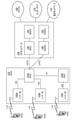
図1は、1つまたは複数の開示された実施形態が実施されることができる例示の通信システム100を示す図である。通信システム100は、複数のワイヤレスユーザに対して、音声、データ、ビデオ、メッセージ、宣伝などの内容を提供する多重アクセスシステムでよい。通信システム100は、複数のワイヤレスユーザが、ワイヤレス帯域幅を含むシステム資源を共有することによってそのような内容にアクセスすることを可能にすることができる。たとえば、通信システム100は、符号分割多重アクセス(CDMA)、時分割多重アクセス(TDMA)、周波数分割多重アクセス(FDMA)、直交FDMA(OFDMA)、単一キャリアFDMA(SC-FDMA)などの1つまたは複数のチャネルアクセス方式を採用することができる。
FIG. 1 is a diagram illustrating an
図1に示されるように、通信システム100は、ワイヤレス送信/受信ユニット(WTRU)102a、102b、102c、102dなどの電子デバイス、無線アクセスネットワーク(RAN)104、コアネットワーク106/107/109、公衆交換電話ネットワーク(PSTN)108、インターネット110、および他のネットワーク112を含むことができるが、開示された実施形態は、任意数のWTRU、基地局、ネットワーク、および/またはネットワーク要素を企図するものであることが理解されよう。WTRU 102a、102b、102c、102dの各々は、ワイヤレス環境において動作し、かつ/または通信するように構成された任意のタイプのデバイスでよい。例として、「局」および/または「STA」と称されることがあるWTRU 102a、102b、102c、102dは、ワイヤレス信号を送信し、かつ/または受信するように構成されてよく、ユーザ機器(UE)、移動局、固定式または移動式の加入者ユニット、ポケットベル、携帯電話、携帯情報端末(PDA)、スマートフォン、ラップトップ、ネットブック、パーソナルコンピュータ、ワイヤレスセンサ、民生用電子機器などを含むことができる。WTRU 102a、102b、102cおよび102dは、区別なくUEと称される。
As shown in FIG. 1, the
通信システム100は、基地局114aおよび/または基地局114bなどの電子デバイスを含むことができる。基地局114a、114bの各々は、WTRU 102a、102b、102c、102dのうち少なくとも1つとワイヤレスで接続してコアネットワーク106/107/109、インターネット110、および/または他のネットワーク112などの1つまたは複数の通信ネットワークに対するアクセスを容易にするように構成された任意のタイプのデバイスでよい。例として、基地局114a、114bは、ベーストランシーバ局(BTS)、ノード-B、eNode B、ホームノードB、ホームeNode B、サイトコントローラ、アクセスポイント(AP)、ワイヤレスルータなどでよい。基地局114a、114bはそれぞれが単一要素として表されているが、基地局114a、114bは、任意数の相互接続された基地局および/またはネットワーク要素を含むことができることが理解されよう。
The
基地局114aはRAN 103/104/105の一部分でよく、これらは、基地局コントローラ(BSC)、無線ネットワークコントローラ(RNC)、中継ノードなどの他の基地局および/またはネットワーク要素(図示せず)も含むこともできる。基地局114aおよび/または基地局114bは、セル(図示せず)と称されことがある特定の地理的領域の範囲内のワイヤレス信号を送信し、かつ/または受信するように構成されてよい。セルはセルセクタにさらに分割されてよい。たとえば、基地局114aに関連したセルが3つのセクタに分割されてよい。したがって、一実施形態では、基地局114aは、セルの各セクタに対して1つずつ、3つのトランシーバを含むことができる。別の実施形態では、基地局114aはMIMO技術を採用してよく、セルの各セクタに対して複数のトランシーバを利用することができる。
基地局114a、114bは、エアインターフェース115/116/117を通じてWTRU 102a、102b、102c、102dのうち1つまたは複数と通信することができ、エアインターフェースは任意の適切なワイヤレス通信リンク(たとえば無線周波数(RF)、マイクロ波、赤外線(IR)、紫外線(UV)、可視光など)でよい。エアインターフェース115/116/117は、任意の適切な無線アクセス技術(RAT)を使用して確立されてよい。
より具体的には、前述のように、通信システム100は多重アクセスシステムでよく、CDMA、TDMA、FDMA、OFDMA、SC-FDMAなど1つまたは複数のチャネルアクセス方式を採用することができる。たとえば、RAN 103/104/105における基地局114aおよびWTRU 102a、102b、102cは、広帯域CDMA(WCDMA)を使用してエアインターフェース115/116/117を確立することができるユニバーサルモバイルテレコミュニケーションシステム(UMTS)地上波無線アクセス(UTRA)などの無線技術を実施してよい。WCDMAは、高速パケットアクセス(HSPA)および/または発展型HSPA(HSPA+)などの通信プロトコルを含むことができる。HSPAは、高速ダウンリンク(DL)パケットアクセス(HSDPA)および/または高速ULパケットアクセス(HSUPA)を含むことができる。
More specifically, as described above, the
別の実施形態では、基地局114aおよびWTRU 102a、102b、102cは、ロングタームエボリューション(LTE)および/またはLTEアドバンスト(LTE-A)を使用してエアインターフェース115/116/117を確立することができる発展型UMTS地上波無線アクセス(E-UTRA)などの無線技術を実施してよい。
In another embodiment,
他の実施形態では、基地局114aおよびWTRU 102a、102b、102cは、IEEE 802.11(すなわちワイヤレスフィデリティ(WiFi)、IEEE 802.16(すなわちワイマックス(WiMAX))、CDMA2000、CDMA2000 1X、CDMA2000 EV-DO、暫定規格2000(IS-2000)、暫定規格95(IS-95)、暫定規格856(IS-856)、グローバル移動体通信システム(GSM)、GSM革新のための高速データレート(EDGE)、GSM EDGE(GERAN)などの無線技術を実施することができる。
In other embodiments, the
図1の基地局114bは、たとえばワイヤレスルータ、ホームノードB、ホームeNode B、またはアクセスポイントでよく、事業所、自宅、乗物、キャンパスなどの局所における無線接続性を助長するために任意の適切なRATを利用することができる。一実施形態では、基地局114bおよびWTRU 102c、102dは、WLANを確立するためにIEEE 802.11などの無線技術を実施してよい。別の実施形態では、基地局114bおよびWTRU 102c、102dは、ワイヤレスパーソナルエリアネットワーク(WPAN)を確立するためにIEEE 802.15などの無線技術を実施してよい。さらに別の実施形態では、基地局114bおよびWTRU 102c、102dは、ピコセルまたはフェムトセルを確立するためにセルラーベースのRAT(たとえばWCDMA、CDMA2000、GSM、LTE、LTE-Aなど)を利用することができる。図1に示されるように、基地局114bはインターネット110に対する直接接続を有することができる。したがって、基地局114bは、インターネット110にアクセスするのにコアネットワーク106/107/109を介する必要はない。
The
RAN 103/104/105はコアネットワーク106/107/109と通信することができ、コアネットワーク106/107/109は、WTRU 102a、102b、102c、102dのうち1つまたは複数に対して音声、データ、アプリケーション、および/またはボイスオーバインターネットプロトコル(VoIP)サービスを提供するように構成された任意のタイプのネットワークでよい。たとえば、コアネットワーク106/107/109は、呼制御、課金サービス、モバイルロケーションベースのサービス、プリペイドコーリング、インターネット接続、ビデオ配信などを提供してよく、かつ/またはユーザ確認など高レベルのセキュリティ機能を実行してもよい。図1には示されていないが、RAN 103/104/105および/またはコアネットワーク106/107/109は、RAN103/104/105と同一のRATまたは別のRATを採用する他のRANと直接的または間接的に通信してよいことが理解されよう。たとえば、コアネットワーク 106/107/109は、e-UTRA無線技術を利用している可能性があるRAN 103/104/105に接続されることに加えて、GSM、UMTS、CDMA 2000、WiMAXまたはWi-Fi無線技術を採用している別のRAN(図示せず)とも通信することができる。
コアネットワーク 106/107/109は、WTRU 102a、102b、102c、102dが、PSTN 108、インターネット110、および/または他のネットワーク112にアクセスするためのゲートウェイとしても働くことができる。PSTN 108は、一般電話サービス(POTS)を提供する回路交換の電話ネットワークを含むことができる。インターネット110は、TCP/IPインターネットプロトコルスイートにおいて送信制御プロトコル(TCP)、ユーザデータグラムプロトコル(UDP)および/またはインターネットプロトコル(IP)などの一般的な通信プロトコルを使用する、相互に接続されたコンピュータネットワークおよびデバイスの地球規模のシステムを含むことができる。ネットワーク112は、他のサービスプロバイダによって所有され、かつ/または動作される、有線および/またはワイヤレスの通信ネットワークを含むことができる。たとえば、ネットワーク112は、RAN 103/104/105と同一のRATまたは別のRATを採用することができる1つまたは複数のRANに接続された別のコアネットワークを含むことができる。
The
通信システム100のWTRU 102a、102b、102c、102dのうちいくつかまたはすべてがマルチモード能力を含むことができる(たとえば、WTRU 102a、102b、102c、102dは、別のワイヤレスリンクを通じて別のワイヤレスネットワークと通信するための複数のトランシーバを含むことができる)。たとえば、図1に示されたWTRU 102cは、セルラーベースの無線技術を採用することができる基地局114a、およびIEEE 802無線技術を採用することができる基地局114bと通信するように構成されてよい。
Some or all of the
図2は例示のWTRU 102を示すシステム図である。図2に示されるように、WTRU 102は、とりわけ、プロセッサ118、トランシーバ120、送信/受信要素122、スピーカ/マイクロフォン124、キーパッド126、ディスプレイ/タッチパッド128、取外し不能記憶装置130、取外し可能記憶装置132、電源134、全地球測位システム(GPS)チップセット136、および/または他の周辺装置138を含むことができる。WTRU 102は、実施形態との整合を保ちながら、前述の要素の任意の部分的組合せを含むことができることが理解されよう。
FIG. 2 is a system diagram showing an
プロセッサ118は、汎用プロセッサ、専用プロセッサ、従来のプロセッサ、デジタル信号プロセッサ(DSP)、複数のマイクロプロセッサ、DSPコアと連携する1つまたは複数のマイクロプロセッサ、コントローラ、マイクロコントローラ、特定用途向け集積回路(ASIC)、フィールドプログラマブルゲートアレイ(FPGA)回路、何らかの他のタイプの集積回路(IC)、ステートマシンなどでよい。プロセッサ118は、信号符号化、データ処理、電力制御、入出力処理、および/またはWTRU 102がワイヤレス環境で動作することを可能にする何らかの他の機能を実行することができる。プロセッサ118は、送信/受信要素122に結合されることができるトランシーバ120に結合されてよい。図2は、プロセッサ118とトランシーバ120を分離した構成要素として表しているが、プロセッサ118とトランシーバ120が電子パッケージまたはチップにおいて一緒に統合されてよいことが理解されよう。
The
送信/受信要素122は、エアインターフェース115/116/117を通じて基地局(たとえば基地局114a)との間で信号を送信/受信するように構成されてよい。たとえば、一実施形態では、送信/受信要素122は、RF信号を送信および/または受信するように構成されたアンテナでよい。別の実施形態では、送信/受信要素122は、たとえば赤外線信号、UV信号、または可視光信号を送信し、かつ/または受信するように構成された放射源/検知器でよい。さらに別の実施形態では、送信/受信要素122は、RF信号と光信号の両方を送信および/または受信するように構成されてよい。送信/受信要素122は、ワイヤレス信号の任意の組合せを送信および/または受信するように構成されてよいことが理解されよう。
The transmit / receive
送信/受信要素122は単一の要素として図2に表されているが、WTRU 102は任意数の送信/受信要素122を含むことができる。より具体的には、WTRU 102はMIMO技術を採用することができる。したがって、一実施形態では、WTRU 102は、エアインターフェース115/116/117を通じてワイヤレス信号を送信したり受信したりするための2つ以上の送信/受信要素122(たとえば複数のアンテナ)を含むことができる。
Although the transmit / receive
トランシーバ120は、送信/受信要素122によって送信される信号を変調したり、送信/受信要素122によって受信された信号を復調したりするように構成されてよい。前述のように、WTRU 102はマルチモード能力を有し得る。したがって、トランシーバ120は、WTRU 102が、たとえばUTRAおよびIEEE802.11など複数のRAT経由で通信することを可能にするための複数のトランシーバを含むことができる。
The
WTRU 102のプロセッサ118は、スピーカ/マイクロフォン124、キーパッド126、および/またはディスプレイ/タッチパッド128(たとえば液晶ディスプレイ(LCD)表示ユニットまたは有機発光ダイオード(OLED)表示ユニット)に結合されてユーザ入力データを受信することができる。プロセッサ118は、スピーカ/マイクロフォン124、キーパッド126、および/またはディスプレイ/タッチパッド128に対してユーザデータを出力することもできる。加えて、プロセッサ118は、取外し不能記憶装置130および/または取外し可能記憶装置132など任意のタイプの適切な記憶装置に対して、情報にアクセスしたり、データを記憶させたりすることができる。取外し不能記憶装置130は、ランダムアクセスメモリ(RAM)、読取り専用メモリ(ROM)、ハードディスク、または何らかの他のタイプのメモリ記憶デバイスを含むことができる。取外し可能記憶装置132は、加入者識別モジュール(SIM)カード、メモリスティック、セキュアデジタル(SD)メモリカードなどを含むことができる。他の実施形態では、プロセッサ118は、サーバまたはホームコンピュータ(図示せず)など、WTRU 102上に物理的に配置されているわけではない記憶装置に対して、情報にアクセスしたり、データを記憶させたりすることができる。
The
プロセッサ118は、電源134から電力を受け取ってよく、WTRU 102における他の構成要素に対して電力を分配および/または制御するように構成されてよい。電源134は、WTRU 102に給電するための任意の適切なデバイスでよい。たとえば、電源134は、1つまたは複数の乾電池バッテリー(たとえばニッケルカドミウム(NiCd)、ニッケル亜鉛(NiZn)、ニッケル金属水素化物(NiMH)、リチウムイオン(Liイオン)など)、太陽電池、燃料電池などを含むことができる。
The
プロセッサ118は、WTRU 102の現在位置に関する位置情報(たとえば経度および緯度)を提供するように構成されることができるGPSチップセット136に結合されてもよい。WTRU 102は、GPSチップセット136からの情報に加えて、もしくはその代わりに、エアインターフェース115/116/117を通じて基地局(たとえば基地局114a、114b)から位置情報を受信してよく、かつ/または2つ以上の近くの基地局から受信されている信号のタイミングに基づいてその位置を決定してよい。WTRU 102は、実施形態との整合を保ちながら、任意の適切な位置決定方法によって位置情報を取得することができることが理解されよう。
プロセッサ118がさらに他の周辺装置138と結合されてよく、他の周辺装置138は、追加の特徴、機能および/または有線もしくはワイヤレスの接続性を提供する1つまたは複数のソフトウェアモジュールおよび/またはハードウェアモジュールを含むことができる。たとえば、周辺装置138は、加速度計、電子コンパス、衛星トランシーバ、デジタルカメラ(写真および/またはビデオ用)、ユニバーサルシリアルバス(USB)ポート、振動デバイス、テレビジョントランシーバ、ハンズフリーヘッドセット、ブルートゥース(登録商標)モジュール、周波数変調(FM)無線ユニット、デジタル音楽プレーヤ、メディアプレーヤ、ビデオゲームプレーヤモジュール、インターネットブラウザなどを含むことができる。周辺装置138が1つまたは複数のセンサを含む場合には、センサは、ジャイロスコープ、加速度計、方位センサ、近接センサ、温度センサ、時間センサ、地理位置センサ、高度計、光センサ、タッチセンサ、磁力計、バロメータ、ジェスチャセンサ、および/または湿度センサのうち1つまたは複数でよい。
The
WTRU 102は全二重無線を含むことができ、全二重無線については、信号のいくつかまたはすべての送信と受信(たとえばUL(たとえば送信用)とダウンリンク(たとえば受信用))の両方のための特定のサブフレームに関連するものが、並行かつ/または同時でよい。全二重無線は、ハードウェア(たとえばチョーク)またはプロセッサ(たとえば個別のプロセッサ(図示せず)またはプロセッサ118)による信号処理のいずれかによって、自己干渉を低減し、および、または実質的に解消するための干渉管理ユニット139を含むことができる。
The
図3は、別の実施形態による、RAN 103およびコアネットワーク106を示すシステム図である。前述のように、RAN 103は、エアインターフェース115を通じてWTRU 102a、102b、102cと通信するためにUTRA無線技術を採用することができる。RAN 103は、コアネットワーク106とも通信することができる。図3に示されるように、RAN 103はノード-B 140a、140b、140cを含むことができ、ノード-B 140a、140b、140cは、それぞれが、エアインターフェース115を通じてWTRU 102a、102b、102cと通信するための1つまたは複数のトランシーバを含む。ノード-B 140a、140b、140cのそれぞれが、RAN 103の範囲内の特定のセル(図示せず)に関連付けられてよい。RAN 103はRNC 142a、142bも含むことができる。RAN 103は、実施形態との整合を保ちながら任意数のノード-BおよびRNCを含むことができることが理解されよう。
FIG. 3 is a system diagram showing the
図3に示されるように、ノード-B 140a、140bはRNC 142aと通信することができる。加えて、ノード-B 140cはRNC 142bと通信することができる。ノード-B 140a、140b、140cは、Iubインターフェースを介して、それぞれのRNC 142a、142bと通信することができる。RNC 142aと142bは、Iurインターフェースを介して互いに通信することができる。RNC 142a、142bの各々が、それに接続されているノード-B 140a、140b、140cを制御するように構成されてよい。加えて、RNC 142a、142bの各々が、外側ループ電力制御、負荷制御、承認制御、パケットスケジューリング、ハンドオーバ制御、マクロダイバーシティ、セキュリティ機能、データ暗号化など他の機能を実行するかまたはサポートするように構成されてよい。
As shown in FIG. 3, the nodes-
図3に示されたコアネットワーク106は、メディアゲートウェイ(MGW)144、移動交換センター(MSC)146、サービングGPRSサポートノード(SGSN)148、および/またはゲートウェイGPRSサポートノード(GGSN)150を含むことができる。前述の要素の各々がコアネットワーク106の一部分として表されているが、これらの要素のうちいかなるものもコアネットワークオペレータ以外のエンティティによって所有されてよく、かつ/または動作されてよいことが理解されよう。
The
RAN 103におけるRNC 142aは、IuCSインターフェースを介してコアネットワーク106のMSC 146に接続されてよい。MSC 146はMGW 144に接続されてよい。MSC 146およびMGW 144は、WTRU 102a、102b、102cに、PSTN 108など回路交換のネットワークへのアクセスを提供することができ、WTRU 102a、102b、102cと従来の陸線通信デバイスの間の通信を容易にする。
The
RAN 103におけるRNC 142aは、IuPSインターフェースを介してコアネットワーク106のSGSN 148にも接続されてよい。SGSN 148はGGSN 150に接続されてよい。SGSN 148およびGGSN 150は、WTRU 102a、102b、102cに、インターネット110などパケット交換のネットワークへのアクセスを提供することができ、WTRU 102a、102b、102cとIP対応デバイスの間の通信を容易にする。
The
前述のように、コアネットワーク106は、他のサービスプロバイダによって所有され、かつ/または動作される、他の有線ネットワークおよび/またはワイヤレスネットワークを含むことができる他のネットワーク112にも接続されてよい。
As mentioned above, the
図4は、実施形態による、RAN 104およびコアネットワーク107を示すシステム図である。前述のように、RAN 104は、エアインターフェース116を通じてWTRU 102a、102b、102cと通信するためにE-UTRA無線技術を採用することができる。RAN 104は、コアネットワーク107とも通信することができる。
FIG. 4 is a system diagram showing the
RAN 104は、eNode-B 160a、160b、160cを含むことができるが、RAN 104は、実施形態との整合を保ちながら任意数のeNode-Bを含むことができることが理解されよう。eNode-B 160a、160b、160cのそれぞれが、エアインターフェース116を通じてWTRU 102a、102b、102cと通信するための1つまたは複数のトランシーバを含むことができる。一実施形態では、eNode-B 160a、160b、160cはMIMO技術を実施することができる。したがって、eNode-B 160aは、たとえば、WTRU 102aへのワイヤレス信号の送信および/またはWTRU 102aからのワイヤレス信号の受信のために、複数のアンテナを使用することができる。
It will be appreciated that the
eNode-B 160a、160b、160cの各々が、特定のセル(図示せず)に関連付けられてよく、無線資源管理決定、ハンドオーバ決定、ULおよび/またはDLにおけるユーザのスケジューリングなどを扱うように構成されてよい。図4に示されるように、eNode-B 160a、160b、160cはX2インターフェースを通じて互いに通信することができる。
Each of the eNode-
図4に示されたコアネットワーク107は、移動性管理エンティティ(MME)162、サービングゲートウェイ(SGW)164、およびパケットデータネットワーク(PDN)ゲートウェイ(またはPGW)166を含むことができる。前述の要素の各々がコアネットワーク107の一部分として表されているが、これらの要素のうちいかなるものもコアネットワークオペレータ以外のエンティティによって所有されてよく、かつ/または動作されてよいことが理解されよう。 The core network 107 shown in FIG. 4 can include a mobility management entity (MME) 162, a serving gateway (SGW) 164, and a packet data network (PDN) gateway (or PGW) 166. Although each of the above elements is represented as part of the core network 107, it will be appreciated that any of these elements may be owned and / or operated by an entity other than the core network operator. ..
MME 162は、S1インターフェースを介してRAN 104におけるeNode-B 162a、162b、162cの各々に接続されてよく、制御ノードとして働くことができる。たとえば、MME 162は、WTRU 102a、102b、102cのユーザの認証、ベアラ活性化/非活性化、WTRU 102a、102b、102cの初期接続(initial attach)中の特定のサービングゲートウェイの選択などを担当することができる。MME 162は、RAN 104と、GSMおよび/またはWCDMAなど他の無線技術を採用する他のRAN(図示せず)との間を切り換えるための制御プレーン機能を提供することができる。
The
サービングゲートウェイ164は、S1インターフェースを介して、RAN 104におけるeNode B 160a、160b、160cの各々に接続されてよい。サービングゲートウェイ164は、WTRU 102a、102b、102cとの間で、ユーザデータパケットを全体的にルーティングしたり転送したりすることができる。サービングゲートウェイ164は、eNode B間のハンドオーバ中のユーザプレーンの固定、WTRU 102a、102b、102cに関するDLデータが有効なときのページングの起動、WTRU 102a、102b、102cのコンテキストの管理および記憶など他の機能を実行することができる。
The serving
サービングゲートウェイ164PDNゲートウェイ166に接続されることができ、PDNゲートウェイ166は、WTRU 102a、102b、102cに、インターネット110などパケット交換のネットワークへのアクセスを提供することができ、WTRU 102a、102b、102cとIP対応デバイスの間の通信を容易にする。
Serving
コアネットワーク107は、他のネットワークとの通信を容易にすることができる。たとえば、コアネットワーク107は、WTRU 102a、102b、102cに、PSTN 108など回路交換のネットワークへのアクセスを提供することができ、WTRU 102a、102b、102cと従来の陸線通信デバイスの間の通信を容易にする。たとえば、コアネットワーク107は、コアネットワーク107とPSTN 108の間のインターフェースとして働くIPゲートウェイ(たとえばIPマルチメディアサブシステム(IMS)サーバ)を含んでよく、またはIPゲートウェイと通信してよい。加えて、コアネットワーク107は、WTRU 102a、102b、102cに、他のサービスプロバイダによって所有され、かつ/または動作される、他の有線ネットワークおよび/またはワイヤレスネットワークを含むことができる他のネットワーク112へのアクセスを提供することができる。
The core network 107 can facilitate communication with other networks. For example, the core network 107 can provide the
図5は、実施形態による、RAN 105およびコアネットワーク109を示すシステム図である。RAN 105は、エアインターフェース117を通じてWTRU 102a、102b、102cと通信するためにIEEE 802.16無線技術を採用するアクセスサービスネットワーク(ASN)でよい。以下でさらに論じられるように、WTRU 102a、102b、102c、RAN 105、およびコアネットワーク109の様々な機能エンティティ間の通信リンクは、基準点として定義されてよい。
FIG. 5 is a system diagram showing the
図5に示されるように、RAN 105は、基地局180a、180b、180c、およびASNゲートウェイ182を含むことができるが、実施形態との整合を保ちながら任意数の基地局およびASNゲートウェイを含むことができることが理解されよう。基地局180a、180b、180cのそれぞれが、RAN 105における特定のセル(図示せず)に関連付けられてよく、それぞれが、エアインターフェース117を通じてWTRU 102a、102b、102cと通信するための1つまたは複数のトランシーバを含むことができる。一実施形態では、基地局180a、180b、180cはMIMO技術を実施することができる。基地局180aは、たとえば、WTRU 102aへのワイヤレス信号の送信および/またはWTRU 102aからのワイヤレス信号の受信のために、複数のアンテナを使用することができる。基地局180a、180b、180cは、ハンドオフ起動、トンネル確立、無線資源管理、トラフィック分類、サービス品質(QoS)ポリシー実施など移動性管理機能も提供することができる。ASNゲートウェイ182は、トラフィック集合ポイントとして働くことができ、ページング、加入者プロファイルのキャッシング、コアネットワーク109へのルーティングなどを担当することができる。
As shown in FIG. 5, the
WTRU 102a、102b、102cとRAN 105の間のエアインターフェース117は、IEEE 802.16規格を実施するR1基準点として定義されてよい。加えて、WTRU 102a、102b、102cの各々が、コアネットワーク109との論理インターフェース(図示せず)を確立することができる。WTRU 102a、102b、102cとコアネットワーク109の間の論理インターフェースは、証明、認証、IPホストコンフィギュレーション管理、および/または移動性管理として使用されることができるR2基準点として定義されてよい。
The
基地局180a、180b、180cの各々の間の通信リンクは、WTRUハンドオーバおよび基地局間のデータ転送を容易にするためのプロトコルを含むR8基準点として定義されてよい。基地局180a、180b、180cとASNゲートウェイ182の間の通信リンクは、R6基準点として定義されてよい。R6基準点は、WTRU 102a、102b、100cの各々関連した移動性イベントに基づいて移動性管理を容易にするためのプロトコルを含むことができる。
The communication link between each of the
図5に示されるように、RAN 105はコアネットワーク109に接続されてよい。RAN 105とコアネットワーク109の間の通信リンクは、たとえば、データ転送能力および移動性管理能力を容易にするためのプロトコルを含むR3基準点として定義されてよい。コアネットワーク109は、モバイルIPホームエージェント(MIP-HA)184と、証明、認証、課金(AAA)サーバ186と、ゲートウェイ188とを含むことができる。前述の要素の各々がコアネットワーク109の一部分として表されているが、これらの要素のうちいかなるものもコアネットワークオペレータ以外のエンティティによって所有されてよく、かつ/または動作されてよいことが理解されよう。
As shown in FIG. 5, the
MIP-HA 184は、IPアドレス管理を担当してよく、WTRU 102a、102b、102cが異なるASNの間および/または異なるコアネットワークの間をローミングすることを可能にすることができる。MIP-HA 184は、WTRU 102a、102b、102cに、インターネット110などパケット交換のネットワークへのアクセスを提供することができ、WTRU 102a、102b、102cとIP対応デバイスの間の通信を容易にする。AAAサーバ186は、ユーザ確認およびユーザサービスのサポートを担当することができる。ゲートウェイ188は、他のネットワークとの相互動作を容易にすることができる。たとえば、ゲートウェイ188は、WTRU 102a、102b、102cに、PSTN 108など回路交換のネットワークへのアクセスを提供することができ、WTRU 102a、102b、102cと従来の陸線通信デバイスの間の通信を容易にする。ゲートウェイ188は、WTRU 102a、102b、102cに、他のサービスプロバイダによって所有され、かつ/または動作される、他の有線ネットワークおよび/またはワイヤレスネットワークを含むことができる他のネットワーク112へのアクセスを提供することができる。
The MIP-
図5には示されていないが、RAN 105は、他のASN、他のRAN(たとえばRAN 103および/または104)に接続されてよく、かつ/または、コアネットワーク109は、他のコアネットワーク(たとえばコアネットワーク106および/または107)に接続されてよいことが理解されよう。RAN 105と他のASNの間の通信リンクは、RAN 105と他のASNの間のWTRU 102a、102b、102cの移動性を調整するためのプロトコルを含むことができるR4基準点として定義されてよい。コアネットワーク109と他のコアネットワークの間の通信リンクは、ホームコアネットワークと訪れたコアネットワークの間の相互作用を容易にするためのプロトコルを含むことができるR5基準として定義されてよい。
Although not shown in FIG. 5, the
WTRUは図1~図5ではワイヤレス端末として説明されているが、特定の代表的な実施形態では、そのような端末が通信ネットワークに対する有線通信インターフェースを(たとえば一時的にまたは永久に)使用してよいことが企図される。 WTRUs are described as wireless terminals in FIGS. 1-5, but in certain exemplary embodiments, such terminals use a wired communication interface to the communication network (eg, temporarily or permanently). Good things are planned.
代表的な実施形態では、他のネットワーク112はWLANでよい。
In a typical embodiment, the
インフラストラクチャ基本サービスセット(BSS)モードのWLANは、BSSのためのAPと、APに関連付けられた1つまたは複数のSTAとを有することができる。APは、分配システム(DS)に対するアクセスもしくはインターフェース、またはBSSとの間でトラフィックを搬送する別のタイプの有線/ワイヤレスのネットワークを有することができる。BSSの外部からのSTAへのトラフィックは、APを通って到達することができ、STAに配送されてよい。STAからBSSの外部の宛先へのトラフィックはAPに送られてよく、それぞれの宛先に配送される。BSSの範囲内のSTA間のトラフィックはAPを介して送られてよく、たとえば出所STAがAPにトラフィックを送ってよく、APが宛先STAにトラフィックを配送してよい。BSSの範囲内のSTA間のトラフィックは、ピアツーピアトラフィックと考えられてよく、かつ/またはピアツーピアトラフィックと称されてよい。ピアツーピアトラフィックは、直接リンクセットアップ(DLS)を用いて、出所STAと宛先STAの間で(たとえば直接)送られてよい。特定の代表的な実施形態では、DLSは、802.11e DLSまたは802.11zトンネルDLS(TDLS)を使用してよい。独立BSS(IBSS)モードを使用するWLANはAPを有しなくてよく、IBSSの範囲内のSTAまたはIBSSを使用しているSTA(たとえばSTAのすべて)は、互いに直接通信することができる。IBSSモードの通信は、本明細書では「アドホック」モードの通信と称されることがある。 A WLAN in Infrastructure Basic Services Set (BSS) mode can have an AP for the BSS and one or more STAs associated with the AP. The AP can have an access or interface to the distribution system (DS), or another type of wired / wireless network that carries traffic to and from the BSS. Traffic from outside the BSS to the STA can reach through the AP and may be delivered to the STA. Traffic from the STA to external destinations in BSS may be sent to the AP and delivered to each destination. Traffic between STAs within the range of BSS may be sent via the AP, for example the source STA may send traffic to the AP and the AP may deliver the traffic to the destination STA. Traffic between STAs within the range of BSS may be considered peer-to-peer traffic and / or may be referred to as peer-to-peer traffic. Peer-to-peer traffic may be sent (eg, directly) between a source STA and a destination STA using a direct link setup (DLS). In certain representative embodiments, the DLS may use an 802.11e DLS or an 802.11z tunnel DLS (TDLS). WLANs that use independent BSS (IBSS) mode do not have to have APs, and STAs within the scope of IBSS or STAs using IBSS (eg, all of STAs) can communicate directly with each other. Communication in IBSS mode is sometimes referred to herein as communication in "ad hoc" mode.
802.11acインフラストラクチャモードの動作または類似のモードの動作を使用しているとき、APはプライマリチャネルなどの固定チャネルでビーコンを送信することができる。プライマリチャネルは、固定幅(たとえば20MHzの帯域幅)でよく、またはシグナリングによって動的に設定される幅でよい。プライマリチャネルはBSSの動作チャネルでよく、STAによってAPとの接続を確立するために使用されてよい。特定の代表的な実施形態では、たとえば802.11システムにおいて、キャリア感知多重アクセス/衝突回避方式(CSMA/CA)が実施されてよい。CSMA/CAについては、APを含むSTA(たとえばすべてのSTA)はプライマリチャネルを感知することができる。特定のSTAによって、プライマリチャネルがビジーであると感知され/検知され、かつ/または決定された場合、この特定のSTAは譲歩してよい。1つのSTA(たとえばたった1つの局)が、所与のBSSにおいて任意の所与の時間に送信することができる。 When using 802.11ac infrastructure mode operation or similar mode operation, the AP may transmit a beacon on a fixed channel, such as the primary channel. The primary channel may be a fixed width (eg, 20 MHz bandwidth) or a width dynamically set by signaling. The primary channel may be the operating channel of the BSS and may be used by the STA to establish a connection with the AP. In certain representative embodiments, carrier sense multiple access (CSMA / CA) may be implemented, for example in an 802.11 system. For CSMA / CA, STAs, including APs (eg, all STAs) can sense the primary channel. If a particular STA senses / detects and / or determines that the primary channel is busy, this particular STA may make concessions. One STA (eg, only one station) can transmit at any given time in a given BSS.
高スループット(HT)STAは、たとえば最初の20MHzのチャネルを隣接した20MHzのチャネルと組み合わせることにより40MHzの幅の連続したチャネルを形成して、通信のために40MHzの幅のチャネルを使用することができる。 High Throughput (HT) STAs may use 40 MHz wide channels for communication, for example by combining the first 20 MHz channels with adjacent 20 MHz channels to form a 40 MHz wide continuous channel. can.
超高スループット(VHT)STAは、20MHz、40MHz、80MHz、および/または160MHzの幅のチャネルをサポートすることができる。40MHzチャネルおよび/または80MHzチャネルは、連続した20MHzチャネルを組み合わせることによって形成されてよい。160MHzチャネルは、8つの連続した20MHzチャネルを組み合わせることにより、または2つの不連続の80MHzチャネルを組み合わせることによって形成されてよく、後者は80+80構成と称されることがある。80+80構成については、データは、チャネル符号化の後に、データを2つのストリームに分割することができるセグメントパーサを通されてよい。それぞれのストリームに対して、逆高速フーリエ変換(IFFT)処理と時間領域処理が別個に施されてよい。ストリームは2つの80MHzチャネルにマッピングされてよく、データは送信STAによって送信されてよい。受信STAの受信機において、80+80構成に関する前述の動作が逆にされてよく、組み合わされたデータは媒体アクセス制御(MAC)に送られてよい。 The ultra-high throughput (VHT) STA can support channels as wide as 20 MHz, 40 MHz, 80 MHz, and / or 160 MHz. The 40 MHz channel and / or the 80 MHz channel may be formed by combining consecutive 20 MHz channels. The 160 MHz channel may be formed by combining eight consecutive 20 MHz channels or by combining two discontinuous 80 MHz channels, the latter of which may be referred to as an 80 + 80 configuration. For 80 + 80 configurations, the data may be channel coded and then passed through a segment parser that can split the data into two streams. Inverse Fast Fourier Transform (IFFT) processing and time domain processing may be performed separately for each stream. The stream may be mapped to two 80 MHz channels and the data may be transmitted by the transmit STA. In the receiver of the receiving STA, the above-mentioned operations relating to the 80 + 80 configuration may be reversed and the combined data may be sent to medium access control (MAC).
802.11afおよび802.11ahによってサブ1GHzの動作モードがサポートされている。802.11afおよび802.11ahでは、チャネル動作帯域幅およびキャリアが、802.11nおよび802.11acにおいて使用されるものに対して低減される。802.11afはテレビホワイトスペース(TVWS)スペクトルにおける5MHz、10MHzおよび20MHzの帯域幅をサポートし、802.11ahは非TVWSスペクトルを使用して、1MHz、2MHz、4MHz、8MHz、および16MHzの帯域幅をサポートする。代表的な実施形態によれば、802.11ahは、マクロカバレッジエリアにおけるMTCデバイスなどのメータタイプ制御/マシンタイプ通信(MTC)をサポートすることができる。MTCデバイスは、たとえば、特定の帯域幅および/または限定された帯域幅をサポートする(たとえばその帯域幅のみサポートする)ことを含む限定された能力といった、特定の能力を有し得る。MTCデバイスは、閾値を上回るバッテリー寿命を有する(たとえば非常に長いバッテリー寿命を保つ)バッテリーを含むことができる。 802.11af and 802.11ah support sub 1GHz operating modes. At 802.11af and 802.11ah, the channel operating bandwidth and carriers are reduced compared to those used in 802.11n and 802.11ac. 802.1af supports 5MHz, 10MHz and 20MHz bandwidths in the TV White Space (TVWS) spectrum, and 802.11ah uses non-TVWS spectra to provide bandwidths of 1MHz, 2MHz, 4MHz, 8MHz, and 16MHz. to support. According to a representative embodiment, 802.11ah can support meter type control / machine type communication (MTC) such as MTC devices in the macro coverage area. MTC devices may have specific capabilities, such as limited capabilities, including, for example, supporting specific bandwidths and / or limited bandwidths (eg, supporting only that bandwidth). The MTC device can include a battery having a battery life above the threshold (eg, having a very long battery life).
マルチチャネルをサポートすることができるWLANシステム、ならびに802.11n、802.11ac、802.11af、および802.11ahなどのチャネル帯域幅は、プライマリチャネルとして指定されることができるチャネルを含む。プライマリチャネルは、BSSにおけるすべてのSTAによってサポートされる最大の共通の動作帯域幅に等しい帯域幅を有することができる。プライマリチャネルの帯域幅は、BSSにおいて動作するすべてのSTAの中から最も小さい帯域幅動作モードをサポートする特定のSTAによって設定され、かつ/または制限されてよい。802.11ahの例では、プライマリチャネルは、APおよびBSSにおける他のSTAが2MHz、4MHz 8MHz、16MHz、および/または他のチャネル帯域幅動作モードをサポートするとしても、1MHzモードをサポートする(たとえば1MHzモードしかサポートしない)STA(たとえばMTCタイプデバイス)を適応させるために、1MHzの幅でよい。キャリア感知および/またはネットワーク配分ベクトル(NAV)設定は、プライマリチャネルの状態に依拠してよい。プライマリチャネルが、たとえばAPに送信している(1MHzの動作モードしかサポートしない)STAのためにビジーであれば、周波数帯の大部分がアイドル状態のままで利用可能であったとしても、周波数帯の利用可能なセットの全体がビジーであると考えられてよい。 WLAN systems capable of supporting multiple channels, as well as channel bandwidths such as 802.11n, 802.11ac, 802.11af, and 802.11ah, include channels that can be designated as primary channels. The primary channel can have a bandwidth equal to the maximum common operating bandwidth supported by all STAs in BSS. The bandwidth of the primary channel may be set and / or limited by a particular STA that supports the smallest bandwidth operating mode of all STAs operating in the BSS. In the example of 802.11ah, the primary channel supports 1MHz mode (eg 1MHz) even though other STAs in AP and BSS support 2MHz, 4MHz 8MHz, 16MHz, and / or other channel bandwidth operating modes. A width of 1 MHz may be sufficient to adapt an STA (eg, an MTC type device) that only supports modes). Carrier sensing and / or network allocation vector (NAV) settings may depend on the state of the primary channel. If the primary channel is busy, for example, for an STA sending to the AP (supporting only 1MHz operating mode), the frequency band will be available even if most of the frequency band remains idle. The entire available set of is considered busy.
米国では、802.11ahによって使用されることができる利用可能な周波数帯は902MHzから928MHzである。韓国では、利用可能な周波数帯は917.5MHzから923.5MHzである。日本では、利用可能な周波数帯は916.5MHzから927.5MHzである。802.11ahに利用可能な全帯域幅は、国コードに依拠して6MHzから26MHzである。 In the United States, the available frequency bands that can be used by 802.11ah are 902 MHz to 928 MHz. In South Korea, the available frequency bands are 917.5 MHz to 923.5 MHz. In Japan, the available frequency bands are 916.5 MHz to 927.5 MHz. The total bandwidth available for 802.11ah is 6MHz to 26MHz, depending on the country code.
802.11acシステムであるWLANのスペクトル効率は、たとえば同一のダウンリンクOFDMシンボル中および/または同一のシンボル時間に関するガード期間中といった同一のシンボル時間中に、複数のSTAに対してダウンリンクMU-MIMO送信を実行することによって改善されることができる。802.11acシステムによって実施されるダウンリンクMU-MIMOは、ダウンリンク送信を実行するのに同一のシンボル時間を使用してよく、言い換えれば、複数のSTAに対するダウンリンク送信の波形の干渉が問題にならないように、複数のSTAに対してシンボルを同時に送信してよい。しかしながら、APを用いるMU-MIMO送信に包含されるすべてのSTAは同一のチャネルまたは帯域を使用しなければならず、したがって、MU-MIMOダウンリンク送信の動作帯域幅は、APを用いるMU-MIMO送信に含まれているSTAによってサポートされるチャネル帯域幅のうち最小のものに制限されてよい。 The spectral efficiency of the 802.11ac system WLAN is downlink MU-MIMO for multiple STAs during the same symbol time, for example during the same downlink OFDM symbol and / or during a guard period for the same symbol time. It can be improved by performing a transmission. The downlink MU-MIMO performed by the 802.11ac system may use the same symbol time to perform the downlink transmission, in other words, the interference of the downlink transmission waveform to multiple STAs is a problem. Symbols may be transmitted to multiple STAs at the same time so as not to be. However, all STAs included in MU-MIMO transmission using AP must use the same channel or bandwidth, so the operating bandwidth of MU-MIMO downlink transmission is MU-MIMO using AP. It may be limited to the minimum channel bandwidth supported by the STA included in the transmission.
WLANは802.11adシステムでよく、媒体アクセス制御(MAC)レイヤおよび物理(PHY)レイヤは60GHz帯においてVHT STAをサポートする。802.11adシステムは、7ギガビット/秒までのデータレートをサポートすることができ、スペクトル拡散モード、単一キャリアモード、およびOFDMモードを含む3つの異なる変調モードをサポートすることができる。その上、802.11adシステムは、世界的に利用可能な60GHzの無認可の帯域を使用することができる。60GHzにおいて波長は5mmであり、802.11adシステムはコンパクトなアンテナおよび/またはコンパクトなアンテナアレイを有することができる。そのようなアンテナおよび/またはアンテナアレイは、狭いRFビームを送信および/または受信することができ、このことは、802.11adシステムにおいて、受信可能範囲を効果的に増加させ、干渉を低減する。加えて、802.11adシステムのフレーム構造は、ビーム形成に関連した発見およびトラッキング動作を含むビーム形成トレーニングを可能にする。1つまたは複数の実施形態によれば、4つの異なるPHYフレーム構造が、異なるPHYフレーム構造の複数の部分において使用されることができるゴレイシーケンスなどのシーケンスの説明を含めて以下で説明される。 The WLAN may be an 802.1ad system and the medium access control (MAC) and physical (PHY) layers support VHT STA in the 60 GHz band. The 802.11ad system can support data rates up to 7 Gbit / sec and can support three different modulation modes, including spectral diffusion mode, single carrier mode, and OFDM mode. Moreover, the 802.11ad system can use the globally available 60 GHz unlicensed band. At 60 GHz the wavelength is 5 mm and the 802.11ad system can have a compact antenna and / or a compact antenna array. Such antennas and / or antenna arrays can transmit and / or receive narrow RF beams, which effectively increases the receivable range and reduces interference in 802.11ad systems. In addition, the frame structure of the 802.11ad system enables beam formation training including discovery and tracking actions related to beam formation. According to one or more embodiments, four different PHY frame structures are described below, including a description of the sequence, such as a Gorey sequence, which can be used in multiple parts of the different PHY frame structure. ..
4つの異なるPHYフレームタイプの構造
図6は実施形態による異なるPHYフレームタイプを示す。
Structure of Four Different PHY Frame Types FIG. 6 shows different PHY frame types according to embodiments.
図6を参照して、米国電気電子技術者協会(IEEE)802.11ad指向性マルチギガビット(DMG)PHY規格に従って動作する802.11adシステムなどのWLANは、フレームタイプ、パケットおよび/またはパケット構造とも称されることがある異なるPHYフレーム構造をサポートすることができる。実施形態によれば、802.11adシステムなど、WLANによってサポートされる4つの異なるPHYフレームタイプは、制御PHYフレームタイプ601、信号キャリアフレームタイプ602、低電力単一キャリアPHYフレームタイプ603、およびOFDM PHYフレームタイプ604を含むことができる。
With reference to FIG. 6, WLANs such as IEEE 802.11ad directional multi-gigabit (DMG) PHY operating according to the Institute of Electrical and Electronics Engineers (IEEE) 802.11ad PHY standard include frame types, packets and / or packet structures. It can support different PHY frame structures that may be referred to. According to embodiments, the four different PHY frame types supported by the WLAN, such as the 802.1ad system, are the control
図7は、実施形態によるプリアンブル構造を示す。 FIG. 7 shows a preamble structure according to an embodiment.
図6および図7を参照して、PHYフレームタイプ601~604は、ショートトレーニングフィールド(STF)605/705およびチャネル推定フィールド(CEF)606/706を含むプリアンブル構造を有することができる。STFフィールドとCEFフィールドの両方が、図7に示されるように、π/2(差動)バイナリ位相偏移キーイング((D)BPSK)変調された繰返しゴレイシーケンスから構築されてよい。特定の実施形態によれば、繰返しゴレイシーケンスのπ/2(D)BPSK変調が実行されてよい。しかしながら、本開示はそれに限定されず、π/2(D)BPSK変調は任意の適切な変形形態によって実行されてよい。
With reference to FIGS. 6 and 7,
図8は実施形態によるビーム形成トレーニングフィールド構造を示す。 FIG. 8 shows a beam forming training field structure according to an embodiment.
図8を参照して、ビーム形成トレーニングフィールド801は、PHYフレームの最後、すなわちPHYフレームのデータフィールドの後に、または後ろに含まれてよい。ビーム形成トレーニングフィールド801は、ビームリファインメントプロセスおよび/またはビームトレーニングプロセスとして使用されてよい。ビーム形成トレーニングフィールド801を含む、PHYフレームタイプ601~604のうちいずれか1つなどのパケットは、ビームリファインメントプロトコル(BRP)パケットと称されることもある。
With reference to FIG. 8, the beam forming
図8を参照して、ビームトレーニングフィールド801の長さを指すことができるトレーニング長さはNによって指示されてよい。いくつかの実施形態では、図8に示されるように、PHYフレームのビーム形成トレーニングフィールド801は4N個の自動利得制御(AGC)サブフィールド802を含むことができ、トレーニング受信/送信(TRN-R/T)フィールド803は5N個のTRN-R/Tサブフィールド804を含む。チャネル推定(CE)サブフィールド805は、図6および図7に示されたCEF 606/706と類似のものおよび/または同一のものでよい。他の実施形態によれば、Nはトレーニングされるアンテナウェイトベクトルの数でよく、1つのAGCブロックは4つのサブフィールドを含むことができ、1つのTRN-R/Tブロックが、4つのR/Tシーケンスおよび1つのCEFなど、5つのサブフィールドを含むことができ、加えて、AGCサブフィールド802およびTRN-R/Tサブフィールド803を含むすべてのサブフィールドが、送信される前に、回転されるπ/2-BPSK変調を使用して変調されてよい。
With reference to FIG. 8, the training length that can refer to the length of the
CEFおよびSTFを構築するのに使用されるゴレイシーケンスは、以下によって定義されてよい。実施形態によれば、ρa(k)は、シーケンスa={a0,a1,・・・,aN-1}の非周期的自己相関でよく、ρa(k)は次式によって明示的に示され、 The Gorey sequence used to construct the CEF and STF may be defined by: According to the embodiment, ρ a (k) may be an aperiodic autocorrelation of the sequence a = {a 0 , a 1 , ..., a N-1 }, and ρ a (k) is given by the following equation. Explicitly shown,

(・)*はその引数の共役である。そこで、(a,b)の対は、ρa(k)+ρb(k)=0、k≠0であればゴレイ相補対と称されてよい。 (・) * Is the conjugate of its argument. Therefore, the pair of (a, b) may be referred to as a Golay complementary pair if ρ a (k) + ρ b (k) = 0 and k ≠ 0.
特定の実施形態によれば、ゴレイ相補対およびゴレイシーケンスは、その固有の特徴のために、ピーク対平均電力軽減、IQアンバランスパラメータの推定、およびチャネル推定として使用されてよい。ゴレイシーケンスの、位相外れの周期的自己相関がゼロになるという特性は、通信システムにおいて有益に使用されることができる。すなわち、ワイヤレス通信における多経路のために、ゴレイシーケンスの複数の遅れた複製、言い換えれば繰返しが受信機に到達する可能性がある。いくつかの実施形態では、チャネルを推定するために、ゴレイシーケンスのシフトされたバージョンは、同一のシーケンスの別のシフトされたバージョンに対して直交してよい。ゴレイシーケンスaの周期的自己相関は、以下に示されるようにca(k)で与えられる。 According to certain embodiments, Golay complementary pairs and Golay sequences may be used for peak vs. average power reduction, IQ imbalance parameter estimation, and channel estimation due to their unique characteristics. The zero out-of-phase periodic autocorrelation characteristic of Gorey sequences can be usefully used in communication systems. That is, due to the multiple paths in wireless communication, multiple delayed duplications of the Gorey sequence, in other words repetitions, can reach the receiver. In some embodiments, the shifted version of the Gorey sequence may be orthogonal to another shifted version of the same sequence in order to estimate the channel. The periodic autocorrelation of the Gorey sequence a is given by c a (k) as shown below.

mod{a,N}はaのNを法とした剰余である。いくつかの実施形態によれば、ゴレイシーケンスaの周期的自己相関は、以下に示されるように、ゴレイシーケンスaの非周期的自己相関の定義を使用して表現されてもよい。 mod {a, N} is the remainder of a modded by N. According to some embodiments, the periodic autocorrelation of the Gorey sequence a may be expressed using the definition of the aperiodic autocorrelation of the Gorey sequence a, as shown below.

したがって、ゴレイ相補対に対して次の表現も当てはまる。
ca(k)+cb(k)=0、k≠0
ゴレイシーケンスaの周期的自己相関と非周期的自己相関の合計がゼロになるというゴレイ相補対のこの特性は、受信機により、相関演算を使用することによってそれぞれのチャネルタップを推定するのに使用されてよい。
Therefore, the following expression also applies to the Golay complementary pair.
c a (k) + c b (k) = 0, k ≠ 0
This characteristic of the Golay complementary pair, where the sum of the periodic and aperiodic autocorrelation of the Golay sequence a is zero, allows the receiver to estimate each channel tap by using a correlation operation. May be used.
長さN=2Mのビームトレーニングフィールドゴレイ相補対は、以下に示す再帰的プロシージャによって構築されてよい。 A beam training field Gorey complementary pair of length N = 2 M may be constructed by the recursive procedure shown below.

ここで here
![]()
![]()
はクロネッカーのデルタであり、wmは回転ベクトルw=[w1 w2 ・・・ wM]のm番目の要素であって|wm|=1であり、dmは遅延ベクトルd=[d1 d2 ・・・ dM]のm番目の要素および[1 2 ・・・ 2M]の並べ替えである。 Is the Kronecker delta, w m is the mth element of the rotation vector w = [w 1 w 2 ... w M ], | w m | = 1, and d m is the delay vector d = [ It is the rearrangement of the m-th element of [d 1 d 2 ... d M ] and [1 2 ... 2 M ].
実施形態によれば、802.11adシステムであるWLANの場合には、対のゴレイ相補シーケンスは前述の方法に基づいて生成されてよく、(Ga32,Gb32)、(Ga64,Gb64)、および(Ga128,Gb128)の3つの対が考えられる。これらの対のパラメータは以下のように列挙される。 According to embodiments, in the case of a WLAN, which is an 802.1ad system, a pair of Golay complementary sequences may be generated based on the method described above, (Ga 32 , Gb 32 ), (Ga 64 , Gb 64 ). , And (Ga 128 , Gb 128 ) are considered. The parameters of these pairs are listed as follows.
![]()
![]()
および and
![]()
![]()
w=[-1 1 -1 1 -1]およびd=[1 4 8 2 16] w = [-1 1 -1 1 -1] and d = [1 4 8 2 16]
![]()
![]()
および and
![]()
![]()
w=[1 1 -1 -1 1 -1]およびd=[2 1 4 8 16 32] w = [1 1 -1 -1 1 -1] and d = [2 1 4 8 16 32]
![]()
![]()
および and
![]()
![]()
w=[-1 -1 -1 -1 1 -1 -1]およびd=[1 8 2 4 16 32 64]
ここでflip{・}はその引数の順番を逆にする関数である。別の実施形態によれば、802.11adシステムの場合には、ゴレイシーケンスは、SC PHYフレームのたとえばGa64によって指示された位置、および低電力SC PHYのたとえばGa64およびGb128によって指示された位置、ならびにビーム形成トレーニングフィールドにおいて使用されてよい。
w = [-1 -1 -1 -1 1 -1 -1] and d = [1 8 2 4 16 32 64]
Here, flip {・} is a function that reverses the order of its arguments. According to another embodiment, in the case of an 802.1ad system, the goray sequence is indicated by the position indicated by, for example, Ga 64 in the SC PHY frame, and by, for example, Ga 64 and Gb 128 in the low power SC PHY. It may be used in the position as well as in the beam forming training field.
IEEEは、IEEE 802.11のPHYレイヤとIEEE 802.11 MACレイヤの両方に対して、MACデータサービスアクセスポイントにおいて測定されたとき少なくとも20ギガバイト/秒の最大のスループットをサポートすることができる少なくとも1つの動作モードを可能にする一方で、局当たりの電力効率を保つかまたは改善する規格化された改良を定義する改正案を開発するために、タスクグループay(TGay)を承認した。この改正案は、45GHzより上でライセンスを免除する帯域に関する動作を定義する一方で、同一の帯域で動作する、IEEE 802.11ad-2012改正案によって定義されたレガシーの指向性マルチギガビット局との後方互換性および共存も保証するものである。 The IEEE can support a maximum throughput of at least 20 gigabytes / second as measured at a MAC data service access point for both the IEEE 802.11 PHY layer and the IEEE 802.11 MAC layer. The task group ay (TGay) has been approved to develop amendments that define standardized improvements that maintain or improve power efficiency per station while enabling two modes of operation. This amendment defines behavior for bands exempt from licenses above 45 GHz, while with legacy directional multi-gigabit stations defined by the IEEE 802.11ad-2012 amendment that operate in the same band. It also guarantees backward compatibility and coexistence.
TGayの主要目的は、少なくとも20ギガバイト/秒の最大スループットであるが、移動性および屋外のサポートの含有も提案されている。スループット、待ち時間、動作環境および用途に関して、10を超える異なる使用事例が提案され、解析されている。802.11ayが従来の規格と同一の帯域において動作する可能性があるので、新技術は、同一の帯域において後方互換性およびレガシーとの共存を提供することが必要とされることがある。 The main objective of TGay is a maximum throughput of at least 20 gigabytes / sec, but it has also been proposed to include mobility and outdoor support. Over 10 different use cases have been proposed and analyzed for throughput, latency, operating environment and applications. Since 802.11ay may operate in the same band as traditional standards, new technologies may need to provide backwards compatibility and coexistence with legacy in the same band.
802.11adおよび802.11ayで使用されるミリメートル波(mmW)帯域の最大スループット要件に到達するために、シングルユーザMIMO(SU-MIMO)、すなわちマルチストリーム、チャネル接合、高次変調および不均一な変調を含む複数の技術が提案されている。より多くの特徴、たとえば屋外および移動性使用事例といった、より広い使用法のシナリオおよび全体システム容量をサポートするために、たとえばマルチユーザMIMO(MU-MIMO)および強化された中継といった他の技術が802.11ayに含まれてよい。 Single-user MIMO (SU-MIMO), ie multi-stream, channel junction, high-order modulation and non-uniformity, to reach the maximum throughput requirements for the millimeter-wave (mmW) band used in 802.1ad and 802.11ay. Multiple techniques including modulation have been proposed. Other technologies, such as multi-user MIMO (MU-MIMO) and enhanced relay, to support wider usage scenarios and overall system capacity, such as more features, eg outdoor and mobile use cases, are 802. It may be included in .11ay.
図9はMIMO送信を実行する流れ図を示す。 FIG. 9 shows a flow chart for executing MIMO transmission.
図9を参照して、動作901において符号化データを生成するために、データ情報ビット900とも称されることがある情報ビット900が、エンコーダパーサ902と、エンコーダ904のうち1つまたは複数とに入力される。実施形態によれば、パケットサイズが非常に大きいときには複数のエンコーダが使用されてよい。エンコーダ904の各々の符号化速度は、変調および符号化方式(MCS)表から選択されてよい。
With reference to FIG. 9, the
動作901で生成された符号化データは、動作903において、MIMO技術を使用して受信機へ同時に送信される複数の空間ストリーム(SS)908を生成するために空間パーサ906に提供されてよい。数量Nssは複数のSSにおけるSSの数を指示してよい。動作905において、複数のSS 908の各々のそれぞれのバイナリシーケンスは、コンスタレーションマッパ910によって複素領域にマッピングされる。実施形態によれば、コンスタレーションマッパ910は、QPSK変調方式、16QAM変調方式、π/2-BPSK変調方式、および/または何らかの他の類似かつ/または適切な変調方式のうちの1つまたは複数に基づいて複数のSS 908をマッピングしてよい。いくつかの実施形態では、複数のSS 908の異なるものに対して異なるコンスタレーション方式および/または変調方式が適用されてよく、適用されるコンスタレーション方式および/または変調方式はMCS表に基づいて決定されてよい。コンスタレーションマッパ910の出力は複素変調シンボルと称されることがあり、実施形態によれば、複素変調シンボルはPHYパケットなどのパケットのデータフィールドに含まれてよい。
The coded data generated in
動作907において、動作905で生成されたそれぞれのPHYパケットのデータフィールドに、ミッドアンブルおよび/またはポストアンブルでもよいプリアンブルが付加されてよく、このプリアンブルは、STF、CEF、およびヘッダフィールドのうち1つまたは複数を含む。実施形態によれば、データフィールドに適用される同一の複素変調または異なる複素変調が、プリアンブルに含まれるフィールドに適用されてよい。MIMO通信をサポートするいくつかの実施形態によれば、複数のSS 908の中の異なる空間ストリームなどの異なる空間ストリームに対して、直交するCEFまたは相互相関の低いCEFが使用されてよい。動作909において、空間マッパ912は、複数のSS 908のすべての空間ストリームの複素変調シンボルを処理する。空間マッパ912は、時空間ブロック符号化(STBC)、(サイクリックシフト(cyclic shifting)ダイバーシティのための)サイクリックシフト、ならびに空間多重再符号化(spatial multiplex recoding)およびビーム形成のうち1つまたは複数を実行することができる。空間マッパ912の出力は送信(TX)チェーンと称されることがある。
In
特定の実施形態によれば、PHYパケットがOFDM PHYパケットである場合には、空間マッパ912によって出力された各TXチェーンの複素シンボルは、動作911において、OFDMシンボルと、マルチキャリア変調器914による逆離散フーリエ変換(IDFT)演算に基づいて生成された時間領域信号とにマッピングされてよい。実施形態によれば、各OFDMシンボルについて時間領域サンプルにガードインターバル(GI)が付加されてよく、GIを付加した後にウィンドウ処理動作が実行されてよい。実施形態によれば、各TXチェーンの複素シンボルが1つまたは複数のDMGアンテナチェーンから送信されてよい。順次のBRP動作ではなく同時のBRP動作をサポートする実施形態によれば、動作913において、1つまたは複数のDMGアンテナチェーンの各々について、データフィールドに対して、トレーニング(TRN)フィールドと称されることがある直交するビーム形成トレーニングフィールドまたは相互相関の低いビームトレーニングフィールドが、それぞれのDMGアンテナチェーンのプリアンブルおよびヘッダフィールドと併せて付加されてよい。DMGアンテナチェーンが、異なるTXチェーンに対してTRNフィールドの同一のセットを使用する場合には、異なるTXチェーンに対するビームリファインメントプロセスは順次に行われてよい。
According to a particular embodiment, when the PHY packet is an OFDM PHY packet, the complex symbol of each TX chain output by the
実施形態によれば、DMGアンテナチェーンの各々に対する動作913の出力が、動作915においてそれぞれのデジタル/アナログコンバータ916に提供され、動作917において、アナログ方式のDMGアンテナチェーンがそれぞれのアナログプリコーダ918によってビーム形成されてよい。アナログプリコーダ918はアナログビーム形成器と称されることがあり、独立して、かつ/または協力し合って動作することができる。
According to embodiments, the output of
MIMO送信のための後方互換性のあるCEFを提供する方法
複数の送信アンテナによる20ギガバイト/秒スループットを提供するため、および/または上回るために、たとえばSU-MIMOといった複数の空間レイヤ送信技術が使用されてよい。SU-MIMOを可能にするためにCEFは互いに直交するべきであり、すなわち、各空間レイヤに対して1つのCEFが、互いに直交するCEFであるように生成され、かつ/または構築されるべきである。802.11ayについては後方互換性およびレガシー802.11adデバイスとの共存が必要とされるので、802.11ay用に使用されるCEFのうちの1つのタイプは、802.11adに使用されるCEFのタイプと同一または類似でよい。それゆえに、802.11ayシステムは、新規のCEFと802.11adのCEFが互いに直交し、しかも同一の特性および/または類似の特性を有するように、1つまたは複数のCEFを識別する必要がある。
How to Provide Backwards Compatible CEF for MIMO Transmission Used by multiple spatial layer transmission technologies, eg SU-MIMO, to provide and / or exceed 20 gigabytes / second throughput with multiple transmit antennas. May be done. To enable SU-MIMO, CEFs should be orthogonal to each other, i.e. one CEF for each spatial layer should be generated and / or constructed to be orthogonal to each other. be. One type of CEF used for 802.11ay is that of the CEF used for 802.11ad, as backwards compatibility and coexistence with legacy 802.11ad devices are required for 802.11ay. It may be the same as or similar to the type. Therefore, the 802.1ay system needs to identify one or more CEFs such that the new CEF and the CEF of 802.11ad are orthogonal to each other and have the same and / or similar properties. ..
実施形態によれば、2つのストリームが一緒に送信されてよく、言い換えれば同時に送信されてよい。そのような場合には、 According to the embodiment, the two streams may be transmitted together, in other words, transmitted at the same time. In such cases,
![]()
![]()
および and
![]()
![]()
は、それぞれ単一キャリアのSTFおよびCEFの最後の128個のサンプルを含むシーケンスと、IEEE 802.11adシステムにおけるOFDM送信を含むシーケンスとでよい。 May be a sequence containing the last 128 samples of STF and CEF of a single carrier, respectively, and a sequence containing OFDM transmission in an IEEE 802.11ad system.
![]()
![]()
は複素数のフィールドである。したがって、実施形態によれば、ベクトルsuvおよびsvuは次式で示されてよく、 Is a complex field. Therefore, according to the embodiment, the vectors s uv and s vu may be expressed by the following equations.

ここで here
![]()
![]()
は変調されたゴレイシーケンスであって次式で表現されてよく、 Is a modulated Goray sequence and may be expressed by the following equation,

ここで here
![]()
![]()
はIEEE 802.11ad規格によって定義されることができるゴレイベクトルであり、 Is a Gorey vector that can be defined by the IEEE 802.11ad standard.
![]()
![]()
は実数のフィールド Is a real field
![]()
![]()
であって、複素平面においてゴレイベクトルの入力を回転させるためのものであり、 And to rotate the input of the Gorey vector in the complex plane,
![]()
![]()
はアダマール積である。 Is the Hadamard product.
図10は、実施形態による、単一キャリア送信のマルチストリーム用のCEFを示す。 FIG. 10 shows a CEF for a single carrier transmission multistream according to an embodiment.
図10を参照して、ストリーム1のための第1のシーケンスは従来のSTFおよび従来のCEF(複数可)に由来するものでよい。ストリーム1のための第1のシーケンスはMSプリアンブルに由来するものでよい。いくつかの実施形態では、ベクトルsuvは802.11adの単一キャリア(SC)送信のためのSTFおよびCEFの最後の部分を含む第1のシーケンスに対応してよく、svuは、802.11ad OFDM送信のSTFおよびCEFの最後の部分のための第2のシーケンスに対応してよい。多経路チャネルの場合、ベクトルsuvおよびsvuの右側と左側に配置されたベクトル
With reference to FIG. 10, the first sequence for
![]()
![]()
および and
![]()
![]()
は、シフトされたバージョンsuvおよびsvuが Is a shifted version of s uv and s vu
![]()
![]()
および and
![]()
![]()
に対する循環シフトをもたらすことを可能にする。 Allows to bring about a circular shift to.
特定の実施形態によれば、2つの並行のストリームが送信される場合には、送信機は、802.11ad規格で定義されたシーケンスすなわちsuvおよびsvuならびにそれらの共役すなわち According to a particular embodiment, when two parallel streams are transmitted, the transmitter is a sequence defined in the 802.1ad standard or s uv and s vu and their conjugates or conjugations.
![]()
![]()
および and
![]()
![]()
を使用することにより、STFの最後の128個のサンプルを含むストリームのCEFを生成してよい。より詳細には、suvおよび May be used to generate a CEF for a stream containing the last 128 samples of STF. More specifically, s uv and
![]()
![]()
はSC送信のストリームのために使用されてよく、また、svuおよび May be used for streams of SC transmission, also s vu and
![]()
![]()
はOFDM送信のストリームのために使用されてよい。その上、suvと May be used for streams of OFDM transmission. Besides, with s uv
![]()
![]()
の対またはsvuと With a pair or s vu
![]()
![]()
の対を使用することによってストリーム間の最大の分離が達成されてよく、ストリーム間の最大の分離は次の観測によって示され、 The maximum separation between streams may be achieved by using a pair of streams, the maximum separation between streams is shown by the following observations,

circshift{a,n}は、シーケンスaに対して左から右へn回の循環シフトを適用する演算子である。 Circshift {a, n} is an operator that applies n circular shifts from left to right for sequence a.
特定の実施形態では、2つのデータストリーム送信のために、CEF用に使用される変調されたシンボルシーケンスが設計されてよい。たとえば、第1のストリーム用のCEFはフォーマット[mGu512,mGv512-mGb128]を有することができ、第2のストリーム用のCEFはフォーマット[mGu512 *,mGv512 *-mGb128 *]を有することができる。第1のストリーム用のCEFおよび第2のストリーム用のCEFに使用される変調されたシンボルは表Aに示されている。第1の列は、π/2 BPSK変調を伴う、第1のストリーム用のCEFに対応する第1の変調されたシンボルを示すことができる。第2の列は、π/2 BPSK変調を伴う、第2のストリーム用のCEFに対応する第2の変調されたシンボルを示すことができる。第3の列は、π/2 BPSK変調なしの、第1のストリーム用のCEFに対応する第1の変調されたシンボルを示すことができる。第4の列は、π/2 BPSK変調なしの、第2のストリーム用のCEFに対応する第2の変調されたシンボルを示すことができる。演算子 In certain embodiments, a modulated symbol sequence used for the CEF may be designed for the transmission of two data streams. For example, the CEF for the first stream can have the format [m Gu512 , m Gv512- m Gb128 ] and the CEF for the second stream can have the format [m Gu512 * , m Gv512 * -m Gb128 * ]. Can have. The modulated symbols used for the CEF for the first stream and the CEF for the second stream are shown in Table A. The first column can show the first modulated symbol corresponding to the CEF for the first stream, with π / 2 BPSK modulation. The second column can show a second modulated symbol corresponding to the CEF for the second stream, with π / 2 BPSK modulation. The third column can show the first modulated symbol corresponding to the CEF for the first stream, without π / 2 BPSK modulation. The fourth column can show the second modulated symbol corresponding to the CEF for the second stream, without π / 2 BPSK modulation. operator
![]()
![]()
はアダマール積に対応する。 Corresponds to the Hadamard product.
図11は、実施形態による、シーケンスsuvおよびsvuの自己相関ゾーンおよび相互相関ゾーンを示す。 FIG. 11 shows the autocorrelation zones and cross-correlation zones of the sequences s uv and s vu according to the embodiment.
図11を参照して、(a)~(d)に示された動作は、 With reference to FIG. 11, the operations shown in (a) to (d) are
![]()
![]()
とそれらの共役がゼロ自己相関ゾーンを有することを指示することができ、(e)~(f)に示された動作は、 And their conjugates can be instructed to have a zero autocorrelation zone, and the behaviors shown in (e)-(f) are:
![]()
![]()
と When
![]()
![]()
の対および Pair and
![]()
![]()
と When
![]()
![]()
の対がゼロ相互相関ゾーンを有することを指示することができる。ベクトル It can be indicated that the pair of is having a zero cross-correlation zone. vector
![]()
![]()
の要素の数が512であるので、ゼロ自己相関ゾーンのサイズは256であり、ゼロ相互相関ゾーンのサイズは256である。したがって、実施形態によれば、提案されたシーケンスはすべての利用可能な自由度を利用することができ、シーケンス間の最大の分離をもたらすことができる。実施形態によれば、シーケンスsuvとsvuが最大の分離を有するので、802.11ad受信機と802.11ay受信機の両方が、ゴレイ相関器を使用することによって±128タップを有するチャネルを推定することができる。 Since the number of elements of is 512, the size of the zero autocorrelation zone is 256 and the size of the zero cross-correlation zone is 256. Therefore, according to embodiments, the proposed sequence can take advantage of all available degrees of freedom and can result in maximum separation between sequences. According to embodiments, both the 802.11ad receiver and the 802.11ay receiver have a channel with ± 128 taps by using a Golay correlator, since the sequences s uv and s vu have the greatest separation. Can be estimated.
特定の実施形態によれば、MIMOシステムにおいて、かつ/またはMIMOシステムの設計に関して、複数のTXアンテナ用のCEF(たとえばパイロット信号および/または基準シーケンス)の直交性が、時空間符号化に類似の技術に基づいて実施され、実行され、かつ/または達成されてよい。いくつかの実施形態では、単一のTXアンテナの場合には、CEFの送信時間はNT倍(NTはTXアンテナの数である)だけ増加されてよい。他の実施形態では、たとえばNT=2といった複数のTXアンテナの場合には、2つのCEFを使用する代わりに1つのCEF(たとえば増加された送信時間を有することができる)が使用されてよい。特定の実施形態によれば、以下で論じられるように、CEFの送信時間を増加させることは、NT=4の場合などNT>2の場合に拡張されてよく、かつ/または適用されてよい。 According to certain embodiments, in the MIMO system and / or with respect to the design of the MIMO system, the orthogonality of the CEFs (eg, pilot signals and / or reference sequences) for multiple TX antennas is similar to spatiotemporal coding. It may be implemented, implemented, and / or achieved on the basis of technology. In some embodiments, in the case of a single TX antenna, the transmission time of the CEF may be increased by NT times ( NT is the number of TX antennas). In other embodiments, in the case of multiple TX antennas, eg NT = 2, one CEF (eg, which can have an increased transmission time) may be used instead of using two CEFs. .. According to certain embodiments, increasing the transmission time of the CEF may be extended and / or applied in the case of NT > 2, such as in the case of NT = 4, as discussed below. good.
図12は、実施形態による、マルチストリーム用の拡張されたCEFを示す。 FIG. 12 shows an extended CEF for multistream by embodiment.
図12を参照して、推定されるチャネルの信号対雑音比(SNR)が増加されることができる。実施形態によれば、CEFの部分(たとえばCEFの With reference to FIG. 12, the signal-to-noise ratio (SNR) of the estimated channel can be increased. According to the embodiment, a portion of the CEF (eg, of the CEF)
![]()
![]()
部分)は、CEFの Part) is of CEF
![]()
![]()
および and
![]()
![]()
を追加することにより、かつ/または繰り返すことによって拡張されてよい。特定の実施形態によれば、拡張されたCEFは特定の場合に使用されてよいが、拡張されていないCEF(複数可)は、たとえば多くの場合に使用されるように、デフォルトCEF構造および/またはベースラインCEF構造であると考えられてよい。特定の実施形態によれば、CEFの部分は、対応するサイクリックサフィックス(cyclic suffix)(たとえばCEFの May be extended by adding and / or repeating. According to certain embodiments, the extended CEF may be used in certain cases, while the unextended CEF (s) are the default CEF structure and /, as is often used, for example. Alternatively, it may be considered to be a baseline CEF structure. According to certain embodiments, the portion of the CEF is the corresponding cyclic suffix (eg, of the CEF).
![]()
![]()
および/または And / or
![]()
![]()
)を追加することによって拡張されてよい。図12は、部分(a)および(b)におけるCEFのそれぞれの拡張を示す。しかしながら、本開示はそれに限定されず、低減されたCEFは、SNRを増加させるために任意の適切な要素および/または類似の要素を含むことができる。 ) May be extended. FIG. 12 shows the respective extensions of CEF in portions (a) and (b). However, the present disclosure is not limited thereto, and the reduced CEF may include any suitable and / or similar elements to increase the SNR.
図13は、実施形態による、マルチストリーム用の低減されたCEFを示す。 FIG. 13 shows a reduced CEF for multistream by embodiment.
図13を参照すると、チャネルおよび/または信号に関連した待ち時間が低減されることができる。実施形態によれば、関連する待ち時間を低減するために、低減されたCEFが使用されてよい。たとえば、低減されたCEFは、 With reference to FIG. 13, the latency associated with the channel and / or the signal can be reduced. According to embodiments, reduced CEFs may be used to reduce the associated latency. For example, the reduced CEF
![]()
![]()
または or
![]()
![]()
しか含まなくてよい。しかしながら、本開示はそれに限定されず、低減されたCEFは、待ち時間を低減するために任意の適切な要素および/または類似の要素を含むことができる。 You only have to include it. However, the present disclosure is not limited thereto, and the reduced CEF may include any suitable and / or similar elements to reduce latency.
複数の送信アンテナを用いてプリアンブルおよびヘッダを送信する方法
802.11ayシステムのレガシー802.11adシステムに対する後方互換性を提供するために、STFおよびCEFを含むプリアンブルと、パケットのヘッダ部分との送信方法を定義する必要がある。
How to transmit preambles and headers using multiple transmit antennas How to transmit preambles, including STFs and CEFs, to the header portion of a packet to provide backwards compatibility with the legacy 802.11ad system of the 802.11ay system. Need to be defined.
図14は、実施形態による、802.11adシステムと802.11ayシステムの相互運用性を示す。 FIG. 14 shows the interoperability of the 802.11ad system and the 802.11ay system according to the embodiment.
図14を参照すると、802.11ad STAでよい802.11ad受信機1401と、802.11ay APでよい802.11ay送信機1402と、802.11ay STAでよい802.11ay受信機1403とが示されている。実施形態によれば、802.11ad受信機1401がうまく復号するために、言い換えれば受信信号を正確に復号するために、ストリーム1の交差チャネルすなわちh11ad、およびMIMOチャネルすなわちh11、h12、h21、およびh22は、それぞれ802.11ad受信機1401および802.11ay受信機1402において推定されてよい。
Referring to FIG. 14, an 802.1
図15は802.11ad受信機のチャネル推定結果を示し、図16は、実施形態による、802.11ay受信機のチャネル推定結果を示す。 FIG. 15 shows the channel estimation result of the 802.11ad receiver, and FIG. 16 shows the channel estimation result of the 802.11ay receiver according to the embodiment.
図14、図15および図16を参照して、ゴレイシーケンスの前述のゼロ相関ゾーン特性を使用する実施形態により、ランダムな指数関数的遅延チャネルに対して、802.11ad受信機1401において推定されるチャネル結果が図15に示されており、802.11ay受信機1403において推定されるチャネル結果が図16に示されている。実施形態によれば、交差チャネルとMIMOチャネルの両方に対して、完全なチャネル推定が達成されることができる。
With reference to FIGS. 14, 15 and 16, by an embodiment using the aforementioned zero correlation zone characteristic of the Gorey sequence, it is estimated at the 802.1
図17は実施形態による802.11ayパケットのヘッダを示す。 FIG. 17 shows a header of an 802.11 ay packet according to an embodiment.
図17を参照して、実施形態によれば、ストリームに関連した情報を送信するために、ゴレイシーケンスの前述のゼロ相関ゾーン特性を使用する実施形態については、SU-MIMO送信のための最小のオーバヘッド設計を提供する一方で追加のヘッダフィールドが含まれてよい。図17に示されるように、第1のストリーム1701および第2のストリーム1702に関連したヘッダ情報は、第1のストリーム1701と第2のストリーム1702の両方によって送信される。802.11ayパケットのオーバヘッドを最小化するために、レガシーヘッダ1703に既存のビットが第1のストリーム1701用に使用されてよい。たとえばSU-MIMOに関連した情報といった、802.11ayの新規の特徴に関連した情報は、第2のストリーム1702によって送信されてよい。実施形態によれば、レガシーヘッダ1703が802.11ad受信機において復号されるように、レガシーヘッダ1703のフォーマットは一定に保たれてよく、第2のストリーム1702のエネルギーレベルは第1のストリーム1701のものよりも低く保たれてよい。
With reference to FIG. 17, according to the embodiment, for embodiments that use the aforementioned zero-correlation zone characteristic of the Gorey sequence to transmit stream-related information, the minimum for SU-MIMO transmission. Additional header fields may be included while providing an overhead design for. As shown in FIG. 17, the header information associated with the
マルチストリームに対するビームトラッキング用のCEFを提供する方法
実施形態によれば、1対のSTAの間に必要とされるリンクバジェット(link budget)を提供するためにBRPが使用されてよい。たとえば、802.11adシステムであるWLANは、対のSTAの両方の、受信機トレーニングと、送信機と受信機の両方のアンテナ設定の反復改善とのために、BRPを使用してよい。BRPについては、802.11ad用に定義されたチャネル推定フィールドが採用されてよく、ビームトレーニング中および/またはビームリファインメント動作中に繰り返し送信されてよい。マルチストリームがサポートされる場合には、既存のBRPの使用を可能にするCEFが必要とされることがある。
Methods of Providing CEFs for Beam Tracking for Multistreams According to embodiments, BRPs may be used to provide the required link budget between a pair of STAs. For example, a WLAN, which is an 802.1ad system, may use BRP for both receiver training and iterative improvement of both transmitter and receiver antenna settings for both pairs of STAs. For BRP, the channel estimation field defined for 802.11ad may be employed and may be transmitted repeatedly during beam training and / or beam refinement operation. If multi-stream is supported, a CEF that allows the use of existing BRPs may be required.
図18は、実施形態による、2つのストリーム用のチャネル推定フィールド(CEF)を示す。 FIG. 18 shows a channel estimation field (CEF) for two streams according to an embodiment.
図17および図18を参照すると、第1のストリーム1801および第2のストリーム1802が、BRPによって使用されてよく、言い換えればBRPメッセージに含まれてよい。実施形態によれば、たとえば802.11ay STA、802.11ay APといった受信機、および/または何らかの他の適切かつ/または類似のデバイスは同時に2つのビームを追跡することができる。そのような場合には、第2のストリーム1802の第2のCEF 1804はBRP用に使用され、言い換えれば、BRPメッセージに含まれる第2のストリーム、およびセクタレベルスイープ(SLS)メッセージに対応する。第2のCEFは、BRPおよびSLS用に使用される第1のストリーム1801の第1のCEF 1803の共役である。実施形態によれば、2×2 MIMOシステムが考えられるとき、上記で説明されたように、第2のストリーム1802用に共役CEFを使用すると、第1のストリーム1801と第2のストリーム1802の間の最大の分離を可能にすることができ、アンテナポート、送信アンテナポートの対、および/または送信機のデジタルプリコーダの入力、ならびに受信アンテナポートおよび/または受信機のデジタルプリコーダの出力について、完全な、かつ/またはほぼ完全なチャネル推定をもたらすことができる。しかしながら、本開示はそれに限定されず、2つ以上のストリームが、BRP用に使用されてよく、かつ/またはBRPメッセージに含まれてよい。
With reference to FIGS. 17 and 18, the
より詳細には、第1のCEF 1603および/または第2のCEF 1604などのCEFは、以下で説明されるようにN≧2であるとき、N個のデータストリームMIMO送信を可能にするように拡張されてよい。実施形態によれば、図23および図24に示されたCEFは、ビームトレーニングフィールドで使用されるCEF、言い換えればBRP用に使用されるCEFおよび/またはBRPメッセージに含まれるCEFとして使用されてよく、かつ/または同CEFに類似のものである。 More specifically, CEFs such as the first CEF 1603 and / or the second CEF 1604 may allow N data stream MIMO transmissions when N ≧ 2 as described below. May be expanded. According to embodiments, the CEFs shown in FIGS. 23 and 24 may be used as CEFs used in beam training fields, in other words CEFs used for BRP and / or CEFs contained in BRP messages. And / or similar to the CEF.
MIMO用のCEF設計
実施形態によれば、複数のストリームを追跡する方法は、N個(N≧2)のデータストリームMIMO送信に適用されてよく、SU-MIMOおよびMU-MIMO送信に適用されてよい。
According to the CEF Design Embodiment for MIMO, the method of tracking multiple streams may be applied to N (N ≧ 2) data stream MIMO transmissions, and is applied to SU-MIMO and MU-MIMO transmissions. good.
図19は実施形態による追加のCEFを示す。 FIG. 19 shows an additional CEF according to an embodiment.
実施形態によれば、空間ストリームと称されることも、データストリームおよび/またはストリームを指すこともある時空間ストリームの数が、2つ以上のとき、MIMOチャネル推定用に追加のCEFが挿入されてよく、かつ/または使用されてよい。CEF1と称されることがある、CEF1として示された追加のCEFは、802.11adで定義された基本的なCEFシーケンスに基づいて構築されてよい。他の実施形態によれば、CEF1は、図19に示されるように、STFからの最後の128個のシンボルを先頭に追加することによって拡張されてよい。特定の実施形態によれば、第1のCEF1 1901はsuvと称されてよく、かつ/または
According to embodiments, an additional CEF is inserted for MIMO channel estimation when the number of spatiotemporal streams, sometimes referred to as spatial streams and may also refer to data streams and / or streams, is two or more. And / or may be used. An additional CEF, sometimes referred to as CEF1, may be constructed based on the basic CEF sequence defined in 802.11ad. According to other embodiments, CEF1 may be extended by prepending the last 128 symbols from STF, as shown in FIG. According to certain embodiments, the
![]()
![]()
によって決定されてよく、SCフレームタイプおよび/またはPHYフレームタイプに使用されてよい。第2のCEF1 1902はsvuと称されてよく、かつ/またはOFDMフレームタイプ用に
It may be determined by and used for SC frame type and / or PHY frame type. The
![]()
![]()
によって決定されてよい。いくつかの実施形態によれば、CEF1と称されることもある追加のCEFは複素変調シンボルでよい。本明細書では、以下、追加のCEFという用語は、図19を参照しながら説明されたCEF1の変形形態から構成されることができるフィールドを指してよい。しかしながら、本開示はそれに限定されず、追加のCEFは、図19を参照しながら説明されたCEF1に基づくものではない変形形態によって構成されてよく、決定されてよく、かつ/または生成されてよい。 May be determined by. According to some embodiments, the additional CEF, sometimes referred to as CEF1, may be a complex modulation symbol. Hereinafter, the term additional CEF may refer to a field that can be composed of variants of CEF1 described with reference to FIG. However, the present disclosure is not limited thereto, and additional CEFs may be configured, determined and / or produced by variants that are not based on CEF1 as described with reference to FIG. ..
本明細書で説明され、かつ/または図示された実施形態を含む特定の実施形態によれば、CEF1とCEFは交換可能でよい。たとえばCEF1はCEFによって置換されてよく、その逆も成立する。 According to certain embodiments described herein and / or including the illustrated embodiments, CEF1 and CEF may be interchangeable. For example, CEF1 may be replaced by CEF and vice versa.
図20は、実施形態による、マルチストリーム用のCEFを示す。 FIG. 20 shows a CEF for multi-stream according to an embodiment.
実施形態によれば、CEFは、様々なやり方、タイプで、かつ/または1つまたは複数のパラメータに基づいて構築されてよい(たとえば構成されてよい、設計されてよい、など)。特定の実施形態によれば、CEFのサイズは多様でよく、たとえば変化されてよい。特定の実施形態によれば、CEF1のサイズは変化されてよく、かつ/または構造に従って構築されてよい。たとえば、CEF1のサイズは、特定のパラメータに関する構造(たとえば適切な構造)に調和して変化されてよい。 According to embodiments, the CEF may be constructed in various ways, types and / or on the basis of one or more parameters (eg, may be configured, may be designed, etc.). According to certain embodiments, the size of the CEF may vary and may vary, for example. According to certain embodiments, the size of the CEF1 may be varied and / or constructed according to the structure. For example, the size of CEF1 may vary in harmony with the structure for a particular parameter (eg, the appropriate structure).
特定の実施形態によれば、推定されるチャネルのSNRを改善するために、CEF1)における According to certain embodiments, in order to improve the SNR of the estimated channel, in CEF1).
![]()
![]()
および/または And / or
![]()
![]()
の対は、図20の部分(a)および(b)に示されるように複製されてよい(たとえば拡張されてよい)。他の実施形態によれば、推定されるチャネルのSNRを改善するために、CEF1における Pairs of may be duplicated (eg, extended) as shown in parts (a) and (b) of FIG. According to other embodiments, in order to improve the SNR of the estimated channel, in CEF1.
![]()
![]()
および/または And / or
![]()
![]()
の対は、図20の部分(c)から(e)に示されるように、 Pairs of are as shown in parts (c) to (e) of FIG.
![]()
![]()
と When
![]()
![]()
の間で低減されてよい(たとえば短縮されてよい)。特定の実施形態によれば、上記の実施形態の要素のいかなる組合せも、推定されるチャネルのSNRを改善するために組み合わされてよい。 May be reduced (eg shortened) between. According to certain embodiments, any combination of the elements of the above embodiments may be combined to improve the estimated channel SNR.
特定の実施形態によれば、CEF1は、様々なやり方、タイプで、かつ/または1つもしくは複数のパラメータに基づいて構成されてよく、かつ/または構築されてよい。そのような場合には、送信機は、CEF1が構築されている構成および/または構造に関連した情報を伝えてよい。特定の実施形態によれば、CEF1の構成および/または構造に関連した情報は、以下で論じられることになる新規のヘッダフィールドに含まれてよい。図20に関連した実施形態のいかなるものにおいても、CEF1はCEFによって置換されてよい。 According to certain embodiments, the CEF1 may be configured and / or constructed in various ways, types and / or based on one or more parameters. In such cases, the transmitter may convey information related to the configuration and / or structure in which the CEF1 is constructed. According to certain embodiments, information relating to the configuration and / or structure of CEF1 may be included in the new header fields that will be discussed below. In any of the embodiments related to FIG. 20, CEF1 may be replaced by CEF.
図21は、実施形態による、MIMO送信のプリアンブルおよびPHYヘッダを示し、図22は、別の実施形態による、MIMO送信のプリアンブルおよびPHYヘッダを示す。 FIG. 21 shows a MIMO transmission preamble and a PHY header according to an embodiment, and FIG. 22 shows a MIMO transmission preamble and a PHY header according to another embodiment.
図21および図22を参照して、1つまたは複数の実施形態によれば、プリアンブルおよびPHYヘッダは、4つのデータストリームを含むMIMO送信用でよい。しかしながら、本開示はそれに限定されず、プリアンブルおよびPHYヘッダはN個のデータストリームを含むMIMO送信用でよい。実施形態によれば、レガシーSTF(L-STF)フィールド、レガシーCEF(L-CEF)フィールドおよびレガシーヘッダ(L-Header)フィールドは、802.11adで使用されるものと同一でよい。あるいは、2番目、3番目、および/または4番目のデータストリームのL-STFフィールド、L-CEFフィールド、およびL-Headerフィールドには、異なるサイクリックシフトが適用されてよい。 With reference to FIGS. 21 and 22, according to one or more embodiments, the preamble and PHY headers may be for MIMO transmission containing four data streams. However, the present disclosure is not limited thereto, and the preamble and PHY headers may be for MIMO transmission containing N data streams. According to embodiments, the legacy STF (L-STF) field, legacy CEF (L-CEF) field and legacy header (L-Header) field may be the same as those used in 802.11ad. Alternatively, different cyclic shifts may be applied to the L-STF, L-CEF, and L-Header fields of the second, third, and / or fourth data streams.
実施形態によれば、L-Headerフィールドの後に、マルチストリーム(MS)ヘッダと称されることもある新規のヘッダが挿入されてよい。新規のヘッダは、受信機が、新規のヘッダはデータ送信の一部分ではないと認めるように、言い換えれば決定するように、802.11adで定義されたデータフィールドから明示的に異なるように符号化されてよい。特定の実施形態によれば、新規のヘッダフィールドおよび/またはMSヘッダフィールドと称されることもある新規のヘッダは、データ送信の前に、新規のヘッダフィールドに追加のCEFがいくつ続くかを伝えるのに使用されるパラメータを包含することができる。特定の実施形態によれば、新規のヘッダは、たとえば図21に示されたCEFの異なる構成のいずれかに関連した情報といった、CEF1の構成および/または構造に関連した情報を包含することができる。 According to embodiments, a new header, sometimes referred to as a multistream (MS) header, may be inserted after the L-Header field. The new header is encoded to be explicitly different from the data field defined in 802.11ad so that the receiver recognizes that the new header is not part of the data transmission, in other words, determines. You can do it. According to certain embodiments, the new header field and / or the new header, sometimes referred to as the MS header field, tells how many additional CEFs follow the new header field before sending the data. Can include the parameters used for. According to certain embodiments, the novel header may include information related to the configuration and / or structure of CEF1, for example information related to any of the different configurations of CEF shown in FIG. ..
実施形態によれば、新規のヘッダフィールドの後に、CEF1と称されることもある追加のCEFが挿入されてよい。受信機は、MIMOチャネル推定のために、追加のCEFをレガシーCEFとともに使用してもよい。使用される追加のCEFの数は時空間ストリームの数に基づいてよい。他の実施形態によれば、M個の時空間ストリームが送信される場合、N個の追加のCEFが使用されてよく、N≧M-1である。たとえば、2つの時空間ストリームが送信される場合、Nは1に等しくてよく、4つの時空間ストリームが送信される場合、Nは3に等しくてよく、3つの時空間ストリームが送信される場合、Nは2または3でよい。しかしながら、本開示はそれに限定されず、Nは、Mに対して適切に対応する任意の値でよい。 According to embodiments, an additional CEF, sometimes referred to as CEF1, may be inserted after the new header field. The receiver may use additional CEFs with legacy CEFs for MIMO channel estimation. The number of additional CEFs used may be based on the number of spatiotemporal streams. According to another embodiment, when M spatiotemporal streams are transmitted, N additional CEFs may be used, N ≧ M-1. For example, if two spatiotemporal streams are transmitted, N may be equal to 1 and if four spatiotemporal streams are transmitted, N may be equal to 3 and three spatiotemporal streams are transmitted. , N may be 2 or 3. However, the present disclosure is not limited thereto, and N may be any value appropriately corresponding to M.
L-STFフィールドおよびL-CEFフィールドからの最後の128個のシンボルと、追加のCEFとを含むことができる拡張L-CEFフィールドを含んでいるCEFフィールドは、図19に示されるように、サイズ(N+1)×(N+1)を有する直交マトリクスVを掛けられてよい。より詳細には、実施形態によれば、j番目の時空間ストリーム用のi番目のCEFフィールドにおけるすべてのシンボルは定数Vijを掛けられてよく、第1のCEFフィールドは前述の拡張L-CEFフィールドでよく、k番目のCEFフィールドは、k>1としてk-1番目のCEF1でよい。Vマトリクスは以下のように定義されてよい。 A CEF field containing an extended L-CEF field that can contain the last 128 symbols from the L-STF and L-CEF fields and an additional CEF is sized as shown in FIG. It may be multiplied by an orthogonal matrix V having (N + 1) × (N + 1). More specifically, according to the embodiment, all symbols in the i-th CEF field for the j-th spatiotemporal stream may be multiplied by the constant V ij , and the first CEF field is the above-mentioned extended L-CEF. It may be a field, and the kth CEF field may be the k-1th CEF1 with k> 1. The V-matrix may be defined as follows.

実施形態によれば、Vマトリクスの第1の列は1に固定されてよい。そのような場合には、異なるストリーム用のレガシーCEFは変更されなくてよく、レガシーデバイスはレガシーヘッダを復号することができる。加えて、Vマトリクスは、たとえば According to embodiments, the first column of the V-matrix may be fixed at 1. In such cases, the legacy CEFs for different streams need not change and the legacy device can decrypt the legacy headers. In addition, the V-matrix is, for example,

または or

といった直交マトリクスとして設計されてよい。しかしながら、本開示はそれに限定されず、他の直交マトリクスが同様に使用されてよい。 It may be designed as an orthogonal matrix such as. However, the present disclosure is not limited thereto, and other orthogonal matrices may be used as well.
実施形態によれば、図22を参照して、空間ストリーム間の直交性を生成するために共役複素数演算子が使用されてよい。しかしながら、本開示は、図22に示されるような追加のCEFフィールドの選択には限定されない。たとえば、図22に示された構成に対して、ストリームに対応する行が交換されてよく、言い換えれば、第3のストリーム2203用の行が第1のストリーム2201と第2のストリーム2202の間に配設されてよく、一方、第4のストリーム2204が第2のストリーム1902に隣接して配設されてよい。
According to embodiments, with reference to FIG. 22, the conjugate complex operator may be used to generate orthogonality between spatial streams. However, the present disclosure is not limited to the selection of additional CEF fields as shown in FIG. For example, for the configuration shown in FIG. 22, the rows corresponding to the streams may be exchanged, in other words, the rows for the
図23は、他の実施形態による、MIMO送信のプリアンブルおよびPHYヘッダを示す。 FIG. 23 shows the preamble and PHY headers of MIMO transmission according to other embodiments.
図23を参照して、図22に示された実施形態は、直交マトリクスVを使用する図21に示された実施形態に対する代替形態と考えられてよい。実施形態によれば、直交マトリクスVの第1の列は1に固定されなくてよい。したがって、第2のストリームから開始して、L-CEFが続くL-STFを送信する代わりに、L-STFおよびL-CEFからの最後の128個のシンボルを含んでいる拡張L-CEFフィールドが、直交Vマトリクスからの係数を掛けられてよい。それゆえに、Vk1*(拡張L-CEF)が送信され、kはストリームインデックスである。同様に、すべてのストリームを通して、L-Headerを直接送信する代わりに、Vk1*L-Headerが送信される。したがって、L-Headerフィールドのアンテナ構成がL-CEFフィールドのものと調和し、レガシーデバイスはL-Headerを復号することができる。実施形態によれば、類似の計略が新規のヘッダフィールドにも適用されてよく、Vは、たとえば With reference to FIG. 23, the embodiment shown in FIG. 22 may be considered as an alternative to the embodiment shown in FIG. 21 using the orthogonal matrix V. According to the embodiment, the first column of the orthogonal matrix V does not have to be fixed at 1. Therefore, instead of sending an L-STF starting from the second stream and followed by the L-CEF, an extended L-CEF field containing the last 128 symbols from the L-STF and L-CEF , May be multiplied by a factor from the orthogonal V matrix. Therefore, V k1 * (extended L-CEF) is transmitted and k is the stream index. Similarly, V k1 * L-Header is transmitted instead of transmitting the L-Header directly through all streams. Therefore, the antenna configuration of the L-Header field is in harmony with that of the L-CEF field, and the legacy device can decode the L-Header. According to embodiments, similar schemes may be applied to new header fields, where V is, for example,

といった802.11n/acで利用されるPマトリクスなど任意の直交マトリクスでよい。 Any orthogonal matrix such as the P matrix used at 802.11n / ac may be used.
図24は、さらに別の実施形態による、プリアンブルおよびPHYヘッダを示す。 FIG. 24 shows a preamble and a PHY header according to yet another embodiment.
図24を参照して、レガシーCEFは、MIMOチャネル推定用の追加のCEFと組み合わされなくてよい。したがって、実施形態によれば、M個のストリーム送信の場合には、N=Mの新規のCEFフィールドが使用されてよい。 With reference to FIG. 24, the legacy CEF does not have to be combined with an additional CEF for MIMO channel estimation. Therefore, according to the embodiment, in the case of M stream transmissions, a new CEF field of N = M may be used.
図25は、実施形態による、プリアンブルおよびPHYヘッダを示す。 FIG. 25 shows the preamble and PHY headers according to the embodiment.
図25を参照して、図10に示された実施形態に対してより小さいオーバヘッドをもたらすCEFが考えられる。特定の実施形態によれば、4つのストリームが送信されることができる場合には、MSプリアンブルにおいて新規のヘッダフィールドの後に挿入されるCEFは2つだけである。第1のストリームと第2のストリームの間の直交性は、サイズ2×2を有する直交マトリクスVによって保たれることができる。第1のストリームは、図10の実施形態に示されたCEFの特性のために、第3のストリームに対して直交する。第1のストリームと第4のストリームは、直交マトリクスVおよび共役複素数演算子が適用されるので相互に直交する。第1、第2、第3、および第4のストリームは任意の順番で配置されてよい。その上、他のストリームは、類似のルールによって相互に直交する。 With reference to FIG. 25, a CEF that results in a smaller overhead with respect to the embodiment shown in FIG. 10 is conceivable. According to a particular embodiment, if four streams can be transmitted, only two CEFs will be inserted after the new header field in the MS preamble. The orthogonality between the first stream and the second stream can be maintained by the orthogonal matrix V having a size of 2 × 2. The first stream is orthogonal to the third stream due to the characteristics of the CEF shown in the embodiment of FIG. The first stream and the fourth stream are orthogonal to each other because the orthogonal matrix V and the conjugate complex operator are applied. The first, second, third, and fourth streams may be arranged in any order. Moreover, the other streams are orthogonal to each other by similar rules.
図25の実施形態によれば、Vは、たとえば According to the embodiment of FIG. 25, V is, for example,

といった任意の2×2直交マトリクスでよい。ストリームインデックス(たとえば図25のストリーム1~ストリーム4)ならびに共役演算および直交マトリクス演算の適用は、任意の順番で交換されてよい。たとえば、第1のストリームは、図10に示されるようなCEFの特性のために第2のストリームと直交する。第1のストリームと第3のストリームは、直交マトリクスVおよび共役複素数演算子が適用されるので相互に直交する。その上、他のストリームは、類似のルールによって相互に直交する。この設計は、異なるサイズの直交マトリクスVを使用することによって任意数の空間ストリーム事例に拡張されてよい。 Any 2 × 2 orthogonal matrix such as may be used. The application of stream indexes (eg, streams 1 to 4 in FIG. 25) as well as conjugate and orthogonal matrix operations may be exchanged in any order. For example, the first stream is orthogonal to the second stream due to the characteristics of the CEF as shown in FIG. The first stream and the third stream are orthogonal to each other because the orthogonal matrix V and the conjugate complex operator are applied. Moreover, the other streams are orthogonal to each other by similar rules. This design may be extended to any number of spatial stream cases by using different sized orthogonal matrices V.
図26は、別の実施形態による、プリアンブルおよびPHYヘッダを示す。 FIG. 26 shows a preamble and a PHY header according to another embodiment.
図26を参照して、追加のCEFによるオーバヘッドはさらに低減されることができる。実施形態によれば、拡張L-CEFフィールドが使用され、MIMOチャネル推定用の追加のCEFと組み合わされてよい。図23には、CEFおよびヘッダ設計を示すために4つのストリーム送信が示されており、必要な追加のCEFは1つだけでよい。図23の実施形態によれば、Vマトリクスは(1)(上記を参照されたい)として定義されてよく、第1の列の要素は1である。したがって、第1のストリームおよび第2のストリームによって送信されるL-STFおよびL-CEFフィールドは、802.11adで使用されるものと同一でよい。第3のストリームおよび第4のストリームの拡張L-CEFは、共役複素数演算を実行することによって変更されてよい。第1のストリームおよび第2のストリームのL-Headerは802.11adで使用されるものと同一でよく、第3のストリームおよび第4のストリームはL-Headerを送信しなくてよい。Vマトリクスおよび共役複素数演算子の第2の列は、図26に示されるようにCEF1に対して適用されてよい。 With reference to FIG. 26, the overhead due to additional CEF can be further reduced. According to embodiments, extended L-CEF fields are used and may be combined with additional CEFs for MIMO channel estimation. FIG. 23 shows four stream transmissions to show the CEF and header design, requiring only one additional CEF. According to the embodiment of FIG. 23, the V-matrix may be defined as (1) (see above), where the element in the first column is 1. Therefore, the L-STF and L-CEF fields transmitted by the first stream and the second stream may be the same as those used in 802.11ad. The extended L-CEF of the third stream and the fourth stream may be modified by performing a conjugate complex operation. The L-Header of the first stream and the second stream may be the same as that used in 802.11ad, and the third and fourth streams do not have to transmit the L-Header. The second column of V-matrix and conjugate complex operator may be applied to CEF1 as shown in FIG.
MIMO送信用のプリアンブルおよびPHYヘッダを含む、上記で論じられた実施形態によれば、MIMO送信に含まれるすべてのストリームにわたって新規のヘッダフィールドが使用されてよく、言い換えれば利用されてよい。しかしながら、本開示はそれに限定されず、新規のヘッダフィールドはストリーム固有のものでよい。 According to the embodiments discussed above, including preambles and PHY headers for MIMO transmission, new header fields may be used, in other words, utilized across all streams contained in MIMO transmission. However, the present disclosure is not limited thereto, and the new header field may be stream-specific.
近接近のマルチストリームユーザのチャネルを推定する方法
複数ユーザに対する送信の場合には、各空間レイヤおよび各ユーザ用に、互いに直交するCEFを使用する必要があり、したがって、適切な直交方法を識別して利用するための方法およびプロシージャが必要とされる。
How to Estimate the Channels of Near-Proximity Multistream Users For transmissions to multiple users, it is necessary to use CEFs that are orthogonal to each other for each spatial layer and each user, thus identifying the appropriate orthogonal method. Methods and procedures are needed to take advantage of it.
図27は、実施形態による、大きな分離度を有するMU送信を示す。 FIG. 27 shows a MU transmission with a large degree of separation according to an embodiment.
図28は、実施形態による、大きな分離度を有するMU送信のためのフレーム構造を示す。 FIG. 28 shows a frame structure for MU transmission with a large degree of separation according to an embodiment.
図29は、実施形態による、小さな分離度を有するMU送信を示す。 FIG. 29 shows an MU transmission with a small degree of separation according to an embodiment.
図30は、実施形態による、小さな分離度を有するMU送信のためのフレーム構造を示す FIG. 30 shows a frame structure for MU transmission with a small degree of separation according to an embodiment.
図27および図28を参照して、MU送信に関しては、各ユーザに向けられているストリームを分離するために、アナログビーム形成、デジタルビーム形成またはハイブリッドビーム形成が使用されてよい。実施形態によれば、各ユーザに向けられているストリームが分離される程度は、ユーザの分離の程度に依拠してよく、分離度は、ユーザの空間的分離およびビーム形成方式の有効性によって決定されてよい。実施形態によれば、MU送信で使用されるCEFは、ユーザの分離度に基づいて適合されてよく、MU送信シナリオのために最も効率的なCEFが送られることを可能にする。 With reference to FIGS. 27 and 28, for MU transmission, analog beam formation, digital beam formation or hybrid beam formation may be used to separate the streams directed to each user. According to embodiments, the degree to which the stream directed to each user is separated may depend on the degree of user separation, and the degree of separation is determined by the user's spatial separation and the effectiveness of the beam formation scheme. May be done. According to embodiments, the CEF used in the MU transmission may be adapted based on the degree of isolation of the user, allowing the most efficient CEF to be delivered for the MU transmission scenario.
実施形態によれば、分離度が大きい場合には、それぞれがCEFのそれぞれのセットを有する独立したストリームが、それぞれのユーザ、すなわちそれぞれのSTAへ同時に送られてよく、STAはチャネル推定をうまく実行することができ、レガシーSTAは送信とうまく共存することができてよく、すなわち、図27および図28に示されるように、ヘッダを復号して、パケットがそれら向けではないと判断することができてよい。 According to embodiments, when the degree of separation is high, independent streams, each with its own set of CEFs, may be sent simultaneously to each user, i.e. each STA, and the STA successfully performs channel estimation. And the legacy STA may be able to co-exist well with the transmission, i.e., as shown in FIGS. 27 and 28, the header can be decoded to determine that the packet is not for them. You can do it.
図29および図30を参照して、別の実施形態によれば、たとえば複数のSTAが同一のビームまたは隣接したビームに存在する可能性がある場合といった、分離度が小さい場合には、CEFが分離可能であってデータが復号可能であることを保証するために追加措置が必要とされることがある。分離可能なCEFは、図29および図30に示されるように、上記で論じられた実施形態に関して詳述された方法およびプロシージャを使用して設計されてよい。実施形態によれば、ヘッダは、各ユーザすなわちSTAを正しいストリームへマッピングする、それぞれのSTAに対応する固有のIDなどの情報を包含することができる。実施形態によれば、各受信機において次式の信号が受信され、
y=hdesiredsdesired+hundesiredsundesired+n
特に、望ましくない信号のエネルギーが、送信ビーム形成に基づく部分的な空間直交性のために所望の信号よりも小さい場合には、hdesiredおよびhundesiredは分離可能なCEFに基づいて知られてよく、所望の信号は各受信機において復号されることができる。
With reference to FIGS. 29 and 30, according to another embodiment, the CEF is used when the degree of separation is small, for example when multiple STAs may be in the same beam or adjacent beams. Additional measures may be required to ensure that the data is separable and decryptable. The separable CEF may be designed using the methods and procedures detailed for the embodiments discussed above, as shown in FIGS. 29 and 30. According to embodiments, the header can include information such as a unique ID corresponding to each STA that maps each user or STA to the correct stream. According to the embodiment, each receiver receives the signal of the following equation.
y = h desired s desired + h undesired s undesired + n
Especially when the energy of the undesired signal is less than the desired signal due to the partial spatial orthogonality based on the transmitted beam formation, h desired and h undesired may be known based on the separable CEF. , The desired signal can be decoded at each receiver.
そのような場合には、実施形態によれば、次のプロシージャが実行されてよい。APは、すべてのSTAに対する最善のビームを識別するために、セクタレベルスイープおよびビームリファインメントプロトコルを実行してよい。APは、STA1およびSTA2を、隣接したビームに存在するものとして識別することができる。APは、図24に示されたフレーム構成を使用して、STA1およびSTA2にマルチユーザ送信を送ってよい。APは、両方のストリームでレガシーSTF、LTFおよびSIGを送信してよい。この場合、各STAは、情報を、大きな遅延の拡散チャネルにおいて送信されているものと理解してよく、言い換えれば、受信し、かつ/または決定してよい。APは、ユーザの数の情報、特定のユーザ情報、および各ユーザが関連付けられているストリームをシグナリングする共通ヘッダを送信してよい。次いで、APは各ユーザにデータを送信してよく、各ユーザにユーザ固有の情報を送信してよい。 In such cases, according to the embodiment, the following procedure may be executed. The AP may perform sector level sweep and beam refinement protocols to identify the best beam for all STAs. The AP can identify STA1 and STA2 as being present in adjacent beams. The AP may send multi-user transmissions to STA1 and STA2 using the frame configuration shown in FIG. The AP may send legacy STFs, LTFs and SIGs on both streams. In this case, each STA may understand that the information is being transmitted on a large delay spreading channel, in other words, receiving and / or determining. The AP may send information about the number of users, specific user information, and a common header signaling the stream with which each user is associated. The AP may then send data to each user and may send user-specific information to each user.
同時のビームトレーニングとMIMO送信のためのトレーニングフィールドを提供する方法
802.11adでは、送信機は複数のDMGアンテナを有することができ、その各々がフェーズドアレイ(phased array)、単一要素アンテナ、またはクワジオムニ(quasi-omni)アンテナパターンによってカバーされるスイッチトビーム(switched beam)アンテナのセットであり得る。802.11adが単一ストリーム送信をサポートするので、各トランシーバにはTX/RXチェーンが1つしかない。したがって、複数のDMGアンテナがあるとき、ビームトレーニングは、各DMGアンテナに対して順次に行われなければならない。加えて、802.11ayでは、複数の空間レイヤが同時に送信され、かつ受信されてよい。これは、複数の空間レイヤに対して、ステアリングベクトルのリファインメントおよび/またはトレーニングのための機会も同時に提供する。この機能をサポートするために、ビームトレーニングフィールドは再設計されなければならない。
How to provide training fields for simultaneous beam training and MIMO transmission In 802.11ad, the transmitter can have multiple DMG antennas, each of which is a phased array, a single element antenna, or It can be a set of switched beam antennas covered by a quasi-omni antenna pattern. Since 802.11ad supports single stream transmission, each transceiver has only one TX / RX chain. Therefore, when there are multiple DMG antennas, beam training must be performed sequentially for each DMG antenna. In addition, in 802.11ay, a plurality of spatial layers may be transmitted and received at the same time. It also provides opportunities for steering vector refinement and / or training for multiple spatial layers at the same time. The beam training field must be redesigned to support this feature.
図31は、2つのストリームのための受信/送信(R/T)シーケンスを示す。 FIG. 31 shows a receive / transmit (R / T) sequence for two streams.
図31を参照して、実施形態によれば、新規のビームトレーニングフィールドは、ステアリングベクトルの同時のリファインメントおよび/またはトレーニングを可能にすることができる。ステアリングベクトルの同時のリファインメントおよび/またはトレーニングを提供する実施形態によれば、受信機は、送信アンテナポートの各対の間のチャネル、および/または送信機のデジタルプリコーダの入力、ならびに受信アンテナポート、および/または受信機のデジタルプリコーダの出力を推定することができ、一方、送信機/受信機はそれ自体のステアリングベクトルを変化させる。このために、ビームトレーニングフィールドにおける完全な自己相関特性および相互相関特性を有するシーケンスは、正確なチャネル推定のために大いに望ましい。シーケンスの最大利用を達成するために、図8に関して上記で論じられた802.11adの変調されたR/Tシーケンスおよびそれらの共役複素数がストリームに採用されてよい。実施形態によれば、シーケンスの最大利用を達成する構成が図31に示されている。 With reference to FIG. 31, according to the embodiment, the new beam training field can allow simultaneous refinement and / or training of the steering vector. According to embodiments that provide simultaneous refinement and / or training of the steering vector, the receiver is the channel between each pair of transmit antenna ports, and / or the input of the transmitter's digital precoder, and the receiver antenna. The output of the digital precoder of the port and / or receiver can be estimated, while the transmitter / receiver changes its own steering vector. For this reason, sequences with perfect autocorrelation and cross-correlation characteristics in the beam training field are highly desirable for accurate channel estimation. In order to achieve maximum utilization of the sequence, the 802.11ad modulated R / T sequences and their conjugate complex numbers discussed above with respect to FIG. 8 may be employed in the stream. According to the embodiment, a configuration that achieves maximum utilization of the sequence is shown in FIG.
図31を参照して、実施形態によれば、TおよびRは、802.11adのR/T用のシーケンスであって、ベクトルTおよびベクトルRは
T=R=[scp smain]
であることを表し、
With reference to FIG. 31, according to the embodiment, T and R are sequences for R / T of 802.11ad, and vector T and vector R are T = R = [s cp s main ].
Represents that
![]()
![]()
および and
![]()
![]()
であるものとする。そこで、それぞれの送信アンテナポートの対の間のチャネル推定、または送信機のデジタルプリコーダの入力のチャネル推定、ならびに受信アンテナポートのチャネル推定、または受信機のデジタルプリコーダの出力のチャネル推定を可能にする以下の引数(a)から(c)が当てはまらなければならない。
(a)circshift{smain,τ}⊥smain|τ|≦128、τ≠0
Suppose that Therefore, it is possible to estimate the channel between a pair of each transmitting antenna port, or the channel estimation of the input of the digital precoder of the transmitter, and the channel estimation of the receiving antenna port, or the channel estimation of the output of the digital precoder of the receiver. The following arguments (a) to (c) must apply.
(A) circshift {s main , τ} ⊥ s main | τ | ≤128, τ ≠ 0
![]()
![]()
![]()
![]()
引数(a)および(b)は、実施形態によれば、シーケンスが、送信アンテナポートの個々の対または送信機のデジタルプリコーダの入力の完全なチャネル推定、ならびに受信アンテナポート、または受信機のデジタルプリコーダの出力の完全なチャネル推定を可能にすることを保証することができるが、引数(c)は、相関(correlation)の後には、受信機において、異なるチャネル間に相互干渉がないことを保証することができる。 Arguments (a) and (b), according to embodiments, are sequences of individual pairs of transmit antenna ports or complete channel estimation of the input of the digital precoder of the transmitter, as well as receive antenna ports, or receivers. Although it can be guaranteed that a complete channel estimation of the output of the digital precoder is possible, the argument (c) is that after correlation, there is no mutual interference between different channels in the receiver. Can be guaranteed.
図32は、実施形態による、引数(a)および(b)のゼロ自己相関ゾーンならびに引数(c)のゼロ相互相関ゾーンを示す。 FIG. 32 shows the zero autocorrelation zone of the arguments (a) and (b) and the zero cross-correlation zone of the argument (c) according to the embodiment.
図32を参照して、提案されたシーケンス、すなわちTおよびT*(またはRおよびR*)に対する引数(a)、(b)、および(c)の結果が示されている。 With reference to FIG. 32, the results of the arguments (a), (b), and (c) for the proposed sequence, T and T * (or R and R * ), are shown.
図33は、実施形態による、R/Tシーケンスの共役複素数を使用するビームトレーニングフィールドを示す。 FIG. 33 shows, according to the embodiment, a beam training field using conjugate complex numbers of the R / T sequence.
図34は、実施形態による、直交Vマトリクスに基づくR/Tシーケンスを使用するビームトレーニングフィールドを示す。 FIG. 34 shows a beam training field using an R / T sequence based on an orthogonal V matrix according to an embodiment.
図33および図34を参照して、実施形態によれば、図31および図32を参照しながら上記で説明された方法は、前述の直交VマトリクスでよいVマトリクスを使用することにより、N個のデータストリームMIMO送信用のビームトレーニングフィールドを可能にするために拡張されてよい。実施形態によれば、複数のアンテナが使用される場合には、802.11ayシステムは複数のアンテナをグループに分割することを選択してよい。各グループの範囲内のアンテナに対して、同時のビームトレーニングと称されることもある並行のビームトレーニングが行われてよく、アンテナのグループは順次にトレーニングされてよい。いくつかの実施形態では、4つのアンテナA1、A2、A3、A4を有する場合には、アンテナA1およびA2は第1のグループG1でよく、アンテナA3およびA4は第2のグループG2でよい。第1のグループG1から送信される信号は、図28に示されるようにビームトレーニングフィールドを使用し、同一の方法が第2のグループG2に適用されてよい。次いで、第1のグループG1のアンテナが最初にトレーニングされ、第2のグループG2のアンテナが後にトレーニングされる。しかしながら、本開示はそれに限定されず、アンテナは任意の適切なやり方でグループ化されてよく、任意の適切なシーケンスで、かつ/または並行してトレーニングされてよい。 With reference to FIGS. 33 and 34, according to the embodiment, the method described above with reference to FIGS. 31 and 32 is N pieces by using a V-matrix which may be the above-mentioned orthogonal V-matrix. May be extended to allow beam training fields for data stream MIMO transmission. According to embodiments, if multiple antennas are used, the 802.11ay system may choose to divide the plurality of antennas into groups. Parallel beam training, sometimes referred to as simultaneous beam training, may be performed on the antennas within the range of each group, and the groups of antennas may be trained sequentially. In some embodiments, when having four antennas A1, A2, A3, A4, the antennas A1 and A2 may be the first group G1 and the antennas A3 and A4 may be the second group G2. The signal transmitted from the first group G1 may use a beam training field as shown in FIG. 28 and the same method may be applied to the second group G2. The antenna of the first group G1 is then trained first and the antenna of the second group G2 is trained later. However, the present disclosure is not limited thereto, and the antennas may be grouped in any suitable manner and may be trained in any suitable sequence and / or in parallel.
シグナリングおよび/または自動検知ビームトレーニングのための方法
順次BRP、同時BRP、または組合せBRPが使用されるかどうかをシグナリングするための方法およびプロシージャが、以下で説明される。実施形態によれば、多重ストリーム用の同時のビーム形成トレーニングが提供される場合には、ビーム形成トレーニングが順次に行われるのか、同時に行われるのか、および/または順次方式と並行方式の組合せとして行われるのか、検知することおよび/または決定することが必要とされる。その上、多重ストリーム用の同時のビーム形成トレーニングをサポートする1つまたは複数のシーケンスが使用されているとシグナリングすることおよび/または指示することも必要とされる。上記で言及された決定および/または指示を行う明示的方法および暗示的方法が、1つまたは複数の実施形態に従って以下で論じられる。
Methods for Signaling and / or Automatic Detection Beam Training Methods and procedures for signaling whether sequential BRP, simultaneous BRP, or combined BRP are used are described below. According to embodiments, when simultaneous beam forming training for multiple streams is provided, whether the beam forming training is done sequentially or simultaneously, and / or as a combination of sequential and parallel methods. It needs to be detected and / or determined. Moreover, it is also required to signal and / or indicate that one or more sequences supporting simultaneous beam forming training for multiple streams are being used. Explicit and implied methods of making the decisions and / or instructions mentioned above are discussed below according to one or more embodiments.
実施形態によれば、制御PHYフレームのレガシーヘッダフィールド、低電力SC PHYフレーム、SC PHYフレーム、および/またはOFDM PHYフレームにおける予約ビットを再解釈し、かつ/または再利用すると、上記で言及された決定および/または指示を提供することができる。実施形態によれば、複数の予約ビットの場合には、これらのビットは連続的な予約ビット、言い換えれば連続した予約ビットおよび/または隣接した予約ビットでよく、不連続の予約ビットでよく、または連続的な予約ビットと不連続の予約ビットの組合せでよい。実施形態によれば、制御PHYヘッダの場合には、2つの予約ビット(開始形式ビット22)が、後方能力を保つために0に設定されるように使用されてよく、受信機に対してレガシーの順次のビーム形成トレーニングのみの使用を指示してよい。2つの予約ビットは、たとえば1、2または3といったゼロでない値のうちいずれかに設定されているとき、同時のビーム形成トレーニングが並行方式および/または順次方式と並行方式の組合せのいずれかによって行われるはずであることを暗示的にシグナリングしてよい。そのような場合には、多重ストリーム用の同時のビーム形成トレーニングをサポートする1つまたは複数のシーケンスのシグナリングは、以下の方法の1つまたは任意の組合せによって実施されてよい。実施形態によれば、第1の方法では、第1の予約ビットは、R/Tシーケンスの共役複素数が使用されるかどうかを指示するために1または0に等しく設定されてよく、同時のビーム形成トレーニングをサポートする。他の実施形態によれば、第2の方法では、第2の予約ビットは、どのVマトリクスが使用されるかを指示するために0または1に等しく設定されてよく、ビーム形成トレーニングを同時にサポートする。たとえば、0および1は、それぞれV2×2マトリクスおよびV4×4マトリクスのインデックスとしてあらかじめ定義されてよい。さらに他の実施形態によれば、第3の方法では、2つの予約ビットのゼロでない値は、R/Tシーケンスの共役複素数が許されなければ、3つのあらかじめ定義されたVマトリクスを指示してよい。 According to embodiments, it is mentioned above that the reserved bits in the legacy header fields of the control PHY frame, the low power SC PHY frame, the SC PHY frame, and / or the OFDM PHY frame are reinterpreted and / or reused. Decisions and / or instructions can be provided. According to embodiments, in the case of a plurality of reserved bits, these bits may be continuous reserved bits, in other words consecutive reserved bits and / or adjacent reserved bits, may be discontinuous reserved bits, or A combination of continuous reserved bits and discontinuous reserved bits may be used. According to embodiments, in the case of control PHY headers, two reserved bits (start format bit 22) may be used to be set to 0 to preserve backward capability and are legacy to the receiver. You may instruct the use of sequential beam formation training only. When the two reserved bits are set to any of the non-zero values, for example 1, 2 or 3, simultaneous beam formation training is performed by either parallel and / or a combination of sequential and parallel methods. It may be implicitly signaled that it should be. In such cases, signaling of one or more sequences supporting simultaneous beam formation training for multiple streams may be performed by one or any combination of the following methods. According to embodiments, in the first method, the first reserved bits may be set equal to 1 or 0 to indicate whether the conjugate complex number of the R / T sequence is used, and the beams are simultaneous. Supports formation training. According to another embodiment, in the second method, the second reserved bit may be set equal to 0 or 1 to indicate which V-matrix is used, simultaneously supporting beam forming training. do. For example, 0 and 1 may be predefined as indexes for the V 2x2 matrix and the V4x4 matrix, respectively. According to yet another embodiment, in the third method, the non-zero values of the two reserved bits indicate three predefined V-matrix if the conjugate complex number of the R / T sequence is not allowed. good.
実施形態によれば、OFDM PHYヘッダの場合には、OFDM PHYヘッダもビット46から始まる2つの予約ビットを有するので、制御PHYヘッダに関して説明されたものと類似の方法および/または同一の方法がOFDM PHYヘッダに適用されてよい。 According to embodiments, in the case of the OFDM PHY header, the OFDM PHY header also has two reserved bits starting with bit 46, so a method similar to and / or the same as that described for the control PHY header is OFDM. It may be applied to the PHY header.
実施形態によれば、低電力(LP)の単一キャリア(SC)PHYヘッダまたはSC PHYヘッダの場合には、ビット44から始まる4つの予約ビットがある。制御PHYヘッダおよびOFDM PHYヘッダに対する適合性を保つために4つの予約ビットのうち2つが再利用される場合には、制御PHYヘッダ向けに提案されたものと同一の方法が、LP SC/SC PHYヘッダに適用されてよい。4つの予約ビットのすべてが再利用されるかまたは再解釈される場合には、ビーム形成トレーニングを同時にシグナリングすることは以下のように実施されてよい。実施形態によれば、4つの予約ビットは、後方能力を保ち、かつレガシーの順次のビーム形成トレーニングが実行されることを指示するために、0に設定されてよい。他の実施形態によれば、4つの予約ビットは、同時のビーム形成トレーニングが並行方式および/または順次方式と並行方式の組合せのいずれかによって行われるはずであることを暗示的にシグナリングするために、4つの予約ビットに対してたとえば1、2、...、15といったゼロでない値に設定されてよい。そこで、多重ストリーム用の同時のビーム形成トレーニングをサポートする1つまたは複数のシーケンスのシグナリングは、以下で説明される方法のうち1つまたは任意の組合せによって実施されてよい。 According to embodiments, in the case of a low power (LP) single carrier (SC) PHY header or SC PHY header, there are four reserved bits starting at bit 44. If two of the four reserved bits are reused to maintain compatibility with the control PHY header and the OFDM PHY header, the same method proposed for the control PHY header is the LP SC / SC PHY. May be applied to the header. If all four reserved bits are reused or reinterpreted, simultaneous signaling of beam forming training may be performed as follows. According to embodiments, the four reserved bits may be set to 0 to indicate that the legacy sequential beam forming training is performed while preserving the backward capability. According to other embodiments, the four reserved bits implicitly signal that simultaneous beam formation training should be performed by either a parallel method and / or a combination of sequential and parallel methods. For example, 1, 2, ... For 4 reserved bits. .. .. , 15 may be set to a non-zero value. Thus, signaling of one or more sequences supporting simultaneous beam formation training for multiple streams may be performed by one or any combination of the methods described below.
実施形態によれば、第1の方法では、たとえば1または0に設定された第1の予約ビットといった、4つの予約ビットのうち任意のものが、同時のビーム形成トレーニングをサポートするためにR/Tシーケンスの共役複素数が使用されるかどうかを指示してよい。他の実施形態によれば、第2の方法では、第1の方法においてR/Tシーケンスの共役複素数を指示するために使用される予約ビットとは別の、残りの予約ビットのうち任意のものが、同時のビーム形成トレーニングをサポートするように使用される対応するVマトリクスを指示するために、1に設定されてよい。他の実施形態では、第2、第3、および第4の予約ビットのうち任意の1つまたは複数が、それぞれV2×2、V4×4およびV8×8マトリクスのインデックスとしてあらかじめ定義されてよい。さらに別の実施形態によれば、第3の方法では、4つの予約ビットのゼロでない値は、R/Tシーケンスの共役複素数が許されなければ、15のあらかじめ定義されたVマトリクスのうち任意の1つまたは複数を指示してよく、あるいは、R/Tシーケンスの共役複素数の使用を可能にする一方で、14のあらかじめ定義されたVマトリクスのうち1つまたは複数を指示してもよい。 According to embodiments, in the first method, any of the four reserved bits, for example the first reserved bit set to 1 or 0, is R / to support simultaneous beam forming training. It may indicate whether the conjugate complex number of the T sequence is used. According to another embodiment, in the second method, any of the remaining reserved bits, separate from the reserved bits used to indicate the conjugate complex number of the R / T sequence in the first method. May be set to 1 to indicate the corresponding V-matrix used to support simultaneous beam forming training. In other embodiments, any one or more of the second, third, and fourth reserved bits are predefined as indexes of the V 2x2 , V4x4, and V8x8 matrices, respectively. It's okay. According to yet another embodiment, in the third method, the non-zero value of the four reserved bits is any of the 15 predefined V-matrixes, provided that the conjugate complex number of the R / T sequence is not allowed. One or more may be specified, or one or more of the 14 predefined V-matrix may be specified while allowing the use of conjugate complex numbers in the R / T sequence.
他の実施形態によれば、新規のヘッダフィールドは、順次に、または並行して、または両方の任意の組合せでトレーニングされるビームに関する情報を指示するために使用されてよい。新規のヘッダは、N個のグループ化されたビームが順次にトレーニングされ、グループ化されたビームの各々の中のM個のストリームが並行してトレーニングされるといった具合に、順次方式と並行方式の両方の組合せをサポートしてよい。Mが1つのストリームを指示する場合には、本実施形態は、既存の802.11ad順次のビーム形成トレーニングを実行してよい。N=1の場合には、本実施形態はビーム形成トレーニングを並行してよい。順次トレーニング方式と並行トレーニング方式のこの種の組合せをサポートするために、M個のストリーム用のレガシーヘッダフィールドの後に新規のヘッダが挿入されてよく、かつ/または新規のヘッダフィールドが、N個のグループ化されたビームの各々に対するM個の同時のビーム形成トレーニング用に使用される新規のシーケンスをシグナリングするのに使用されるパラメータを包含してよい。レガシーヘッダは、802.11adにおける、N個のグループ化されたビームが順次にトレーニングされることをシグナリングし、かつ/または指示するためのものと同一でよい。 According to other embodiments, the new header field may be used to indicate information about the beam to be trained sequentially, in parallel, or in any combination of both. The new headers are sequential and parallel, with N grouped beams being trained sequentially, M streams in each of the grouped beams being trained in parallel, and so on. Both combinations may be supported. If M points to one stream, the present embodiment may perform existing 802.1ad sequential beam forming training. When N = 1, the present embodiment may be parallel with beam forming training. To support this kind of combination of sequential and parallel training methods, new headers may be inserted after the legacy header fields for M streams and / or N new header fields. It may include parameters used to signal a novel sequence used for M simultaneous beam formation training for each of the grouped beams. The legacy header may be the same as in 802.11ad for signaling and / or instructing that N grouped beams be sequentially trained.
図35は、実施形態による、順次のビーム形成トレーニングと並行のビーム形成トレーニングの組合せのためのPHYヘッダを示す。 FIG. 35 shows a PHY header for a combination of sequential beam formation training and parallel beam formation training according to an embodiment.
図35を参照して、順次のビーム形成トレーニングと並行のビーム形成トレーニングとの組合せ用のPHYヘッダは、実施形態によれば、N個のグループ化されたビームが順次にトレーニングされることを指示するレガシーヘッダを含むことができ、N個のグループ化されたビームの各々について、N個のグループ化されたビームの各々の2つのストリームが同時にトレーニングされるように、M=2であることを指示する新規のヘッダを含むことができる。 With reference to FIG. 35, the PHY header for the combination of sequential beam forming training and parallel beam forming training indicates that N grouped beams are sequentially trained according to the embodiment. For each of the N grouped beams, M = 2 so that two streams of each of the N grouped beams can be trained simultaneously. It can contain a new header to indicate.
他の実施形態によれば、ビーム形成トレーニング方法の自動検知は、ストリームのビーム形成トレーニングが順次に行われるのか同時に行われるのかを暗示的にシグナリングしてよく、かつ/または順次のトレーニングと同時のトレーニングの組合せをシグナリングしてよい。並行のビーム形成トレーニングまたは順次のビーム形成トレーニングと並行のビーム形成トレーニングの組合せを、レガシーの順次のビーム形成トレーニングから区別するために、レガシーヘッダ用と新規のヘッダ用の異なる変調間の切換えが、ビーム形成トレーニングのために選択された方法を暗示的にシグナリングするビーム形成トレーニング方法の自動検知の使用を指示してよく、かつ/またはシグナリングしてよい。たとえば、ビーム形成トレーニング方法の自動検知は、LP-SC/SCヘッダ、制御PHYヘッダ、およびOFDM PHYヘッダに対して、異なるPHYヘッダにおける新規のヘッダフィールドの対応する変調の位相の同一または異なる程度の回転および/またはシフト、すなわち、それぞれπ/2-BPSK変調、π/2-DBPSK変調、QPSK-OFDM変調を、シグナリングしてよく、かつ/または指示してよい。 According to another embodiment, the automatic detection of the beam forming training method may implicitly signal whether the beam forming training of the stream is performed sequentially or simultaneously, and / or simultaneously with the sequential training. Training combinations may be signaled. Switching between different modulations for legacy headers and new headers to distinguish parallel beam formation training or a combination of sequential beam formation training and parallel beam formation training from legacy sequential beam formation training. You may direct and / or signal the use of automatic detection of beam forming training methods that implicitly signal the method selected for beam forming training. For example, automatic detection of beam formation training methods may, for LP-SC / SC headers, control PHY headers, and OFDM PHY headers, have the same or different degree of phase of the corresponding modulation of the new header fields in different PHY headers. Rotation and / or shift, ie π / 2-BPSK modulation, π / 2-DBPSK modulation, QPSK-OFDM modulation, may be signaled and / or indicated, respectively.
図36は、実施形態による、LP-SC/SC PHYヘッダのための同時のビーム形成トレーニングの自動検知を示す。 FIG. 36 shows the automatic detection of simultaneous beam forming training for the LP-SC / SC PHY header according to the embodiment.
図36を参照して、LP-SCフレームまたはSC PHYフレームにおいて、レガシーヘッダはπ/2-BPSKによって変調され、新規のヘッダは、π/2-BPSKに対してπ/4だけシフトされ、かつ/または回転されるように、シグナリングされ、かつ/または指示される。π/4シフトされたπ/2-BPSKは、MS SC PHYフレームのレガシーヘッダに対して45°だけ回転された新規のヘッダのコンスタレーションをもたらす。受信機は、π/2-BPSKがπ/4だけ回転されていることを検知し、かつ/または決定したとき、並行のビーム形成トレーニングおよび/または順次のビーム形成トレーニングと並行のビーム形成トレーニングの組合せのいずれかでよい同時のビーム形成トレーニングを行うように暗示的にシグナリングされる。 With reference to FIG. 36, in the LP-SC frame or SC PHY frame, the legacy header is modulated by π / 2-BPSK, the new header is shifted by π / 4 with respect to π / 2-BPSK, and / Or signaled and / or instructed to be rotated. The π / 4 shifted π / 2-BPSK results in a new header constellation rotated 45 ° with respect to the legacy header of the MS SC PHY frame. When the receiver detects and / or determines that π / 2-BPSK is rotated by π / 4, parallel beam formation training and / or sequential beam formation training and parallel beam formation training. Implicitly signaled to perform simultaneous beam formation training good in any of the combinations.
他の実施形態によれば、ストリームはBRPの自動利得制御(AGC)フィールドによってインデックスを付けられてよく、受信機は、AGCフィールドにおいてシーケンスを検査し、かつ/または決定することにより、トレーニングされるべきストリームを識別してよい。そのような場合には、
c=[c1 c2 c3 c4]
であり、
ci∈{1,2,...,16}
である。そこで、4つの各ストリームを有するシーケンスは、
sstream(c)=[s(c1) s(c2) s(c3) s(c4)]
となるはずであり、
According to other embodiments, the stream may be indexed by the automatic gain control (AGC) field of the BRP and the receiver is trained by inspecting and / or determining the sequence in the AGC field. You may identify the stream to be. In such cases,
c = [c 1 c 2 c 3 c 4 ]
And
c i ∈ {1, 2,. .. .. , 16}
Is. So, a sequence with each of the four streams
s stream (c) = [s (c 1 ) s (c 2 ) s (c 3 ) s (c 4 )]
Should be

であり、sign(・)は符号関数であって、flip{・}はその引数のシーケンスの順番を逆にするものである。 Sign (・) is a sign function, and flip {・} reverses the order of the sequence of its arguments.
図37は、AGCフィールドにおいて異なるシーケンスを使用することによってトレーニングされるビームの暗黙の検知を示す。 FIG. 37 shows the implicit detection of a beam trained by using different sequences in the AGC field.
図37を参照して、異なるs(c)も考えられてよく、受信機は、トレーニングされるべき1つまたは複数のビームを識別するために1つまたは複数のシーケンスを検査してよく、かつ/または決定してよい。たとえば、sstream1([1 2 2 2])およびsstream2([2 2 2 2])のシーケンスを有する2つのストリームがある場合、対応するシーケンスは、それぞれ With reference to FIG. 37, different s (c) may also be considered, the receiver may inspect one or more sequences to identify one or more beams to be trained, and / Or may decide. For example, if there are two streams with sequences of s stream1 ([1 2 2 2]) and s stream 2 ([2 2 2 2]), the corresponding sequences will be, respectively.
![]()
![]()
および and
![]()
![]()
として得られる。 Obtained as.
そのような場合には、実施形態によれば、受信機は、Ga64が存在するかどうかを検査し、かつ/または決定する。Ga64はsstream1の第一象限に出現するので、受信機は、ストリーム1に関連したビームのみがトレーニングされることになると理解し、かつ/または決定する。シーケンスの位置は図34に示されている。実施形態によれば、ベクトルcのサイズは実装形態およびゴレイシーケンスの違い(different)に依拠して変化してよく、たとえば、s(c)に関して、異なるサイズを有するゴレイシーケンスが考えられてよい。加えて、シグナリングにおけるオーバヘッドの小さな増加で自動検知プロセスを簡単にするために、前述のビームトレーニング方法の自動検知の明示的方法および暗示的方法が連帯的に使用されてよい。たとえば、受信機が、より小さい検索空間でAGCフィールド構成を検知することができるように、s(c)が2つのグループに分割されてよく、どちらのグループが使用されるかを指示するためにシグナリングが使用されてよい。
In such cases, according to the embodiment, the receiver checks and / or determines if Ga 64 is present. Since Ga 64 appears in the first quadrant of s
図38は、ワイヤレスネットワークにおけるMIMO通信用の複数のチャネルに対するチャネル推定のための情報を送信するステップの例示的流れ図を示す。 FIG. 38 shows an exemplary flow chart of the steps of transmitting information for channel estimation to a plurality of channels for MIMO communication in a wireless network.
図38を参照して、BRPによって使用される、またはBRPメッセージに含まれる、2つのストリームがあると想定されている。実施形態によれば、STA(たとえば802.11ay STA)、AP(たとえば802.11ay AP)、および/または何らかの他の適切なデバイスが2つのストリームを同時に追跡してよい。たとえば、電子デバイスは、動作3810において、第1のチャネルに関連付けられた第1のチャネル推定信号を備える複素数の第1のセットを決定するように構成されてよい。
With reference to FIG. 38, it is assumed that there are two streams used by or contained in the BRP message. According to embodiments, STAs (eg, 802.11ay STAs), APs (eg, 802.11ay APs), and / or some other suitable device may track the two streams simultaneously. For example, the electronic device may be configured in
電子デバイスは、動作3820において、第2のチャネルに関連付けられた第2のチャネル推定信号を備える複素数の第2のセットを決定するように構成されてもよい。特定の実施形態によれば、複素数の第2のセットは複素数の第1のセットの共役複素数である。いくつかの実施形態によれば、第2のストリームに対して共役複素数を使用すると、第1のストリームと第2のストリームの間の最大の分離を可能にすることができる。たとえば、2×2 MIMOシステムの場合には、第2のストリームに対して共役複素数を使用すると、アンテナポート、送信アンテナポートの対、および/または送信機のデジタルプリコーダの入力、ならびに受信アンテナポートおよび/または受信機のデジタルプリコーダの出力についての完全な、かつ/またはほぼ完全なチャネル推定をもたらすことができる。
The electronic device may be configured in
電子デバイスは、動作3830において、物理レイヤ(PHY)フレームによって複素数の第1のセットおよび複素数の第2のセットに構成されてよい。しかしながら、本開示はそれに限定されず、3つ以上のストリームがBRP用に使用されてよく、かつ/またはBRPメッセージに含まれてよい。
The electronic device may be configured in
図39は、ワイヤレスネットワークにおけるMIMO通信用の複数のチャネルのチャネル推定を実行するステップの例示的流れ図を示す。 FIG. 39 shows an exemplary flow chart of the steps of performing channel estimation of multiple channels for MIMO communication in a wireless network.
実施形態によれば、STA(たとえば802.11ay STA)の受信機、AP(たとえば802.11ay AP)、および/または何らかの他の適切なデバイスが2つのストリームを同時に追跡してよい。図39を参照して、電子デバイスは、動作3910において、第1のチャネル推定信号を備える複素数の第1のセットと、第2のチャネル推定信号を備える複素数の第2のセットとを受信するように構成されてよい。
According to embodiments, a receiver of an STA (eg, 802.11ay STA), an AP (eg, 802.11ay AP), and / or some other suitable device may track the two streams simultaneously. With reference to FIG. 39, the electronic device is configured to receive, in
電子デバイスは、次いで、動作3920において、第1のチャネル推定信号に基づいて第1のチャネルを決定し、第2のチャネル推定信号に基づいて第2のチャネルを決定するように構成されてよい。いくつかの実施形態によれば、複素数の第1のセットおよび複素数の第2のセットは、たとえば物理レイヤ(PHY)フレームによって受信されてよい。別の実施形態によれば、複素数の第2のセットは複素数の第1のセットの複素共役数でよい。実施形態によれば、2×2 MIMOシステムが考えられるとき、上記で説明されたように、第2のストリーム用に共役複素数を使用すると、第1のストリームと第2のストリームの間の最大の分離を可能にすることができ、アンテナポート、送信アンテナポートの対、および/または送信機のデジタルプリコーダの入力、ならびに受信アンテナポートおよび/または受信機のデジタルプリコーダの出力について、完全な、かつ/またはほぼ完全なチャネル推定をもたらすことができる。
The electronic device may then be configured in
図40は、ワイヤレスネットワークにおけるMIMO通信用の送信ビーム形成を実行するステップの別の例示的流れ図を示す。実施形態によれば、STA(たとえば802.11ay STA)、AP、および/または何らかの他の適切か類似のデバイスが、ビーム形成のこれらの方法を実行するように構成されてよい。 FIG. 40 shows another exemplary flow chart of the steps of performing transmit beam formation for MIMO communication in a wireless network. According to embodiments, STAs (eg, 802.11ay STAs), APs, and / or some other suitable or similar device may be configured to perform these methods of beam formation.
図40を参照して、電子デバイスは、動作4010において、SLSおよびBRPを実行して、1つまたは複数のSTAのうち任意のものおよび/またはすべてのためのビームを識別するように構成されてよい。
With reference to FIG. 40, the electronic device is configured to perform SLS and BRP in
電子デバイスは、動作4020において、隣接したビームに配設された第1のSTAおよび第2のSTAを識別するように構成されてよい。実施形態によれば、ヘッダは、各ユーザ(たとえばSTA)を正しいストリームへマッピングする、それぞれのSTAに対応する固有のIDなどの情報を包含することができる。実施形態によれば、各受信機において、次式の信号が受信されてよく、
y=hdesiredsdesired+hundsiredsundesired+n
特に、望ましくない信号のエネルギーが、送信ビーム形成に基づく部分的な空間直交性のために所望の信号よりも小さい場合には、hdesiredおよびhundesiredは分離可能なCEFに基づいて知られることができ、所望の信号は各受信機において復号されることができる。
The electronic device may be configured to identify a first STA and a second STA disposed in adjacent beams in
y = h desired s desired + h undsired s undesired + n
Especially when the energy of the undesired signal is less than the desired signal due to the partial spatial orthogonality based on the transmitted beam formation, h desired and h undesired may be known based on the separable CEF. The desired signal can be decoded at each receiver.
電子デバイスは、動作4030において、第1のチャネルに対応する第1のストリームの情報および第2のチャネルに対応する第2のストリームの情報を含むPHYフレームを使用して、第1のSTAおよび第2のSTAへマルチユーザ送信を送信するように構成されてよい。
In
電子デバイスは、動作4040において、ユーザ固有の情報を、第1のSTAおよび第2のSTAへ、PHYフレームにおいて同時に送信するように構成されてよい。いくつかの実施形態では、PHYフレームは、第1のストリームと第2のストリームの両方に、レガシーSTF、LTF、およびSIGを含むことができる。特定の実施形態によれば、PHYフレームは、1つまたは複数のSTAの情報と、第1のストリームを第1のSTAに関連付けるとともに第2のストリームを第2のSTAに関連付ける情報とを含んでいる共通ヘッダを含むことができる。
The electronic device may be configured in
本明細書で説明された解決策は、802.11特有のプロトコルを考えるものであるが、このシナリオに限定されず、他のワイヤレスシステムに対して同様に適用可能であることが理解される。実施形態によれば、図1~図40を参照しながら本明細書で説明された、MIMO通信用のチャネル推定および同時のビーム形成トレーニングのための方法、装置、およびシステムは、任意の適切な、かつ/または類似のワイヤレスシステム、通信システム、および/または無線インターフェースに適用されてよい。 Although the solution described herein considers a protocol specific to 802.11, it is understood that it is not limited to this scenario and is similarly applicable to other wireless systems. According to embodiments, the methods, devices, and systems for channel estimation and simultaneous beam formation training for MIMO communication described herein with reference to FIGS. 1-40 are any suitable. And / or similar wireless systems, communication systems, and / or wireless interfaces.
解決策および提供された例を通じて、たとえば図14および図18の第2のストリームのホワイトスペースといった図のブランク領域は、この領域に対する制約がなく、任意の解決策がそこに採用されることができることを意味してよい。 Through the solution and the examples provided, the blank area of the figure, for example the white space of the second stream of FIGS. 14 and 18, is not constrained to this area and any solution can be adopted therein. May mean.
特定の組合せにおける特徴および要素が上記で説明されているが、当業者なら、それぞれの特徴または要素が、単独で、または他の特徴および要素との任意の組合せで使用されることができるのを理解するであろう。加えて、本明細書で説明された方法は、コンピュータプログラム、ソフトウェア、またはコンピュータもしくはプロセッサによって実行するようにコンピュータ可読媒体に組み込まれたファームウェアで実施されてよい。非一時的コンピュータ可読記憶媒体の例は、それだけではないが、読取り専用メモリ(ROM)、ランダムアクセスメモリ(RAM)、レジスタ、キャッシュメモリ、半導体メモリ素子、内部ハードディスクおよび取外し可能ディスクなどの磁気媒体、光磁気媒体、およびCD-ROMディスクなどの光媒体、およびデジタル多用途ディスク(DVD)を含む。WRTU、UE、端末、基地局、RNC、または任意のホストコンピュータに用いる無線周波数トランシーバを実施するために、ソフトウェアと連携するプロセッサが使用されてよい。 The features and elements in a particular combination are described above, but one of ordinary skill in the art will appreciate that each feature or element can be used alone or in any combination with other features and elements. You will understand. In addition, the methods described herein may be performed with computer programs, software, or firmware embedded in a computer-readable medium for execution by a computer or processor. Examples of non-temporary computer-readable storage media are, but are not limited to, magnetic media such as read-only memory (ROM), random access memory (RAM), registers, cache memory, semiconductor memory elements, internal hard disks and removable disks. Includes photomagnetic media, optical media such as CD-ROM discs, and digital multipurpose discs (DVDs). A processor that works with software may be used to implement a radio frequency transceiver for use in WRTUs, UEs, terminals, base stations, RNCs, or any host computer.
その上、前述の実施形態では、処理プラットホーム、コンピューティングシステム、コントローラ、およびプロセッサを包含している他のデバイスが注目される。これらのデバイスは、少なくとも1つの中央処理装置(「CPU」)および記憶装置を包含することができる。コンピュータプログラミングの当業者の慣行によれば、行為への参照と、動作または命令の象徴的表現とは、様々なCPUおよび記憶装置によって実行されてよい。そのような行為ならびに動作または命令は、「実行される」、または「コンピュータ実行される」または「CPU実行される」と称されることがある。 Moreover, in the aforementioned embodiments, attention is paid to other devices including processing platforms, computing systems, controllers, and processors. These devices can include at least one central processing unit (“CPU”) and storage device. According to the practice of those skilled in the art of computer programming, references to actions and symbolic representations of actions or instructions may be performed by various CPUs and storage devices. Such actions and actions or instructions may be referred to as "executed", or "computer executed" or "CPU executed".
当業者なら、行為ならびに象徴的に表された動作または命令は、CPUによる電気信号の操作を含むことを理解するであろう。電気システムが表すデータビットは、電気信号の変換または低減ならびに記憶システムの記憶場所におけるデータビットの維持をもたらすことができ、それによってCPUの動作ならびに信号の他の処理を再構成し、そうでなければ変更する。データビットが保たれる記憶場所は、データビットに対応する、またはデータビットを表す、特定の電気特性、磁気特性、光学的特性、有機特性を有する物理的位置である。 Those skilled in the art will appreciate that actions and symbolically represented actions or instructions include manipulation of electrical signals by the CPU. The data bits represented by the electrical system can result in the conversion or reduction of the electrical signal and the retention of the data bit in the storage location of the storage system, thereby reconstructing the operation of the CPU and other processing of the signal, otherwise. If you change it. The storage location in which a data bit is retained is a physical location with specific electrical, magnetic, optical, or organic properties that corresponds to or represents the data bit.
データビットは、磁気ディスク、光ディスク、およびCPU可読の何らかの他の揮発性大容量記憶システム(たとえばランダムアクセスメモリ(「RAM」))もしくは不揮発性大容量記憶システム(たとえば読取り専用メモリ(「ROM」))を含むコンピュータ可読媒体に保たれてもよい。コンピュータ可読媒体は、協働するかまたは相互に接続されたコンピュータ可読媒体を含むことができ、これは、もっぱら処理システム上に存在するか、あるいは、処理システムに対してローカルまたはリモートでよい複数の相互に接続された処理システムの間に分散している。代表的な実施形態は前述の記憶装置に限定されず、他のプラットホームおよび記憶装置が、説明された方法をサポートしてよいことが理解される。 The data bits are magnetic disks, optical discs, and some other CPU-readable volatile high-capacity storage system (eg, random access memory (“RAM”)) or non-volatile high-capacity storage system (eg, read-only memory (“ROM”)). ) May be kept on a computer readable medium. Computer-readable media can include collaborative or interconnected computer-readable media, which may reside exclusively on the processing system or may be local or remote to the processing system. Distributed among interconnected processing systems. It is understood that typical embodiments are not limited to the storage devices described above, and that other platforms and storage devices may support the methods described.
本出願の説明で使用された要素、行為または命令は、明示的に説明されたのでなければ、本発明にとって重要なものまたは必須のものと解釈されるべきではない。加えて、冠詞「ある(a)」は、本明細書で使用されたとき、1つまたは複数の項目を含むように意図されている。1つだけの項目が意図されている場合には、「1つの」という用語または類似の言語が使用される。さらに、複数の項目および/または複数のカテゴリの項目の列挙に続く「のいずれか」という用語は、本明細書で使用されたとき、それらの項目および/または項目のカテゴリの、単独あるいは他の項目および/または他のカテゴリの項目「のいずれか」、「の任意の組合せ」、「の任意の複数」および/または「の複数の任意の組合せ」を含むことが意図されている。さらに、「セット」という用語は、本明細書で使用されたとき、ゼロを含めて任意数の項目を含むように意図されている。さらに、「数」という用語は、本明細書で使用されたとき、ゼロを含めて任意の数を含むように意図されている。 The elements, acts or orders used in the description of this application should not be construed as important or essential to the invention unless expressly described. In addition, the article "is (a)" is intended to include one or more items as used herein. If only one item is intended, the term "one" or a similar language is used. In addition, the term "any" following an enumeration of items in multiple items and / or multiple categories, as used herein, alone or in other categories of those items and / or categories. It is intended to include items and / or other categories of items "any", "any combination of", "any combination of" and / or "any combination of". In addition, the term "set" is intended to include any number of items, including zeros, as used herein. Moreover, the term "number" is intended to include any number, including zeros, as used herein.
その上、特許請求の範囲は、説明された順番または要素に(その効果が明示されていなければ)限定されるように読み取られるべきではない。加えて、いずれかの請求項における「手段」という用語の使用は、米国特許法第112条第6段落を引用するように意図されており、「手段」という単語を伴わないいかなる請求項も、そのようには意図されていない。
Moreover, the claims should not be read to be limited to the order or elements described (unless the effect is explicitly stated). In addition, the use of the term "means" in any claim is intended to cite
適切なプロセッサは、例として、汎用プロセッサ、専用プロセッサ、従来のプロセッサ、デジタル信号プロセッサ(DSP)、複数のマイクロプロセッサ、DSPコアと連携する1つまたは複数のマイクロプロセッサ、コントローラ、マイクロコントローラ、特定用途向け集積回路(ASIC)、特定用途向け標準製品(ASSP)、フィールドプログラマブルゲートアレイ(FPGA)回路、何らかの他のタイプの集積回路(IC)、および/またはステートマシンを含む。 Suitable processors include, for example, general purpose processors, dedicated processors, conventional processors, digital signal processors (DSPs), multiple microprocessors, one or more microprocessors working with DSP cores, controllers, microprocessors, specific applications. Includes integrated circuits for applications (ASICs), application-specific standard products (ASSPs), field programmable gate array (FPGA) circuits, some other type of integrated circuits (ICs), and / or state machines.
ソフトウェアと連携するプロセッサは、ワイヤレス送受信ユニット(WRTU)で用いる無線周波数トランシーバ、ユーザ機器(UE)、端末、基地局、移動性管理エンティティ(MME)もしくは発展型パケットコア(EPC)、または任意のホストコンピュータを実施するように使用されてよい。WRTUは、ソフトウェア無線(SDR)と、カメラ、ビデオカメラモジュール、テレビ電話、スピーカフォン、振動デバイス、スピーカ、マイクロフォン、テレビジョントランシーバ、ハンズフリーヘッドセット、キーボード、ブルートゥース(登録商標)モジュール、周波数変調(FM)無線ユニット、近距離無線通信(NFC)モジュール、液晶ディスプレイ(LCD)表示ユニット、有機発光ダイオード(OLED)表示ユニット、デジタル音楽プレーヤ、メディアプレーヤ、ビデオゲームプレーヤモジュール、インターネットブラウザ、および/または任意のWLANもしくはウルトラワイドバンド(UWB)モジュールなどの他の構成要素とを含む、ハードウェアおよび/またはソフトウェアで実施されているモジュールとともに使用されてもよい。 The processor that works with the software can be a radio frequency transceiver, user equipment (UE), terminal, base station, mobility management entity (MME) or advanced packet core (EPC), or any host used in a wireless transmit / receive unit (WRTU). It may be used to implement a computer. WRTU includes software radio (SDR), cameras, video camera modules, videophones, speakerphones, vibrating devices, speakers, microphones, television transceivers, hands-free headsets, keyboards, Bluetooth® modules, frequency modulation ( FM) Wireless Unit, Near Field Communication (NFC) Module, LCD Display Unit, Organic Light Emitting Diode (OLED) Display Unit, Digital Music Player, Media Player, Video Game Player Module, Internet Browser, and / or Optional May be used with modules implemented in hardware and / or software, including with other components such as WLAN or Ultra Wideband (UWB) modules.
本発明は通信システムに関して説明されてきたが、これらのシステムはマイクロプロセッサ/汎用コンピュータ(図示せず)上のソフトウェアで実施されてよいように企図されている。特定の実施形態では、様々な構成要素の機能のうち1つまたは複数は、汎用コンピュータを制御するソフトウェアで実施されてよい。 Although the present invention has been described with respect to communication systems, these systems are intended to be implemented in software on a microprocessor / general purpose computer (not shown). In certain embodiments, one or more of the functions of the various components may be implemented in software that controls a general purpose computer.
加えて、本明細書では、本発明が特定の実施形態を参照しながら示され、かつ説明されているが、本発明は、示された細部に限定されるようには意図されていない。むしろ、様々な修正形態が、本発明から逸脱することなく、特許請求の範囲の等価物の限界および範囲の範囲内で、細部において作製されることができる。 In addition, although the invention is shown and described herein with reference to specific embodiments, the invention is not intended to be limited to the details shown. Rather, various modifications can be made in detail within the limits and scope of the claims without departing from the invention.


Claims (22)
前記WTRUによって、(1)複素数の第1のセットに関連付けられた情報を含んでおり、第1のキャリアに関連付けられた第1のチャネルのための第1のチャネル推定信号、および、(2)複素数の第2のセットに関連付けられた情報を含んでおり、第2のキャリアに関連付けられた第2のチャネルのための第2のチャネル推定信号を決定するステップと
前記WTRUによって、(1)第1のWTRUに関連付けられた第1の周波数を有し、複素数の前記第1のセットを含む前記第1のチャネル推定信号を運んでいる前記第1のキャリア、および、(2)第2のWTRUに関連付けられた第2の周波数を有し、複素数の前記第2のセットを含む前記第2のチャネル推定信号を運んでいる前記第2のキャリアの同時送信を含む物理レイヤ(PHY)フレームを送信するステップと
を含み、
複素数の前記第1のセットは、π/2バイナリ位相偏移キーイング(BPSK)変調されたゴレイ相補シーケンスであり、
複素数の前記第2のセットは、複素数の前記第1のセットの共役複素数である、
方法。 A wireless transmit / receive unit (WTRU) that includes a transmitter, receiver, and processor to transmit channel estimation information associated with multicarrier and multipoint transmission and reception for multi-input multi-output (MIMO) communication in a wireless network. It ’s a method,
According to the WTRU, (1) the first channel estimation signal for the first channel associated with the first carrier, which contains the information associated with the first set of complex numbers , and (2). By the step of determining the second channel estimation signal for the second channel associated with the second carrier , which contains the information associated with the second set of complex numbers and said WTRU, (1). The first carrier having the first frequency associated with the first WTRU and carrying the first channel estimation signal containing the first set of complex numbers, and (2) the second. A physical layer (PHY) frame containing the simultaneous transmission of the second carrier having the second frequency associated with the WTRU and carrying the second channel estimation signal containing the second set of complex numbers. Including steps to send
The first set of complex numbers is a π / 2 binary phase shift keying (BPSK) modulated Golay complementary sequence.
The second set of complex numbers is the conjugate complex number of the first set of complex numbers.
Method.
前記第2のチャネル推定信号は、前記第2のチャネルを推定するためのシーケンスを示している情報を含む、
請求項1に記載の方法。 The first channel estimation signal contains information indicating a sequence for estimating the first channel.
The second channel estimation signal includes information indicating a sequence for estimating the second channel.
The method according to claim 1.
前記第2のチャネル推定信号は、任意の数の第2のSTFおよび任意の数の第2のCEFを含み、
前記第1のチャネルは任意の数の第1のCEFに従って推定され、
前記第2のチャネルは任意の数の第2のCEFに従って推定される、
請求項1に記載の方法。 The first channel estimation signal includes an arbitrary number of first short training fields (STF) and an arbitrary number of first channel estimation fields (CEF).
The second channel estimation signal includes an arbitrary number of second STFs and an arbitrary number of second CEFs.
The first channel is estimated according to any number of first CEFs.
The second channel is estimated according to any number of second CEFs.
The method according to claim 1.
(1)前記第1のチャネル推定信号に対応するレガシープリアンブルおよびレガシーヘッダ、および
(2)前記第1のチャネル推定信号と前記第2のチャネル推定信号の両方に対応するマルチストリーム(MS)プリアンブルおよびMSヘッダのうちのいずれか
を含むように構成された、請求項1に記載の方法。 The PHY frame is
(1) Legacy preambles and legacy headers corresponding to the first channel estimation signal, and (2) Multistream (MS) preambles and (2) corresponding to both the first channel estimation signal and the second channel estimation signal. The method of claim 1, configured to include any of the MS headers.
前記MSプリアンブルは、1つまたは複数のMS STFと1つまたは複数のMS CEFとを含む、請求項8に記載の方法。 The legacy preamble includes one or more legacy short training fields ( STF ) and one or more legacy channel estimation fields ( CEF ) .
The method of claim 8 , wherein the MS preamble comprises one or more MS STFs and one or more MS CEFs.
空間ストリームの前記数は、前記MSプリアンブル内のCEFの数Nに関する情報を含む、請求項8に記載の方法。 The MS header indicates the number of spatial streams in the PHY frame.
The method of claim 8 , wherein said number of spatial streams comprises information about the number N of CEFs in the MS preamble.
送信機、受信機、およびプロセッサを備え、
前記プロセッサは、(1)複素数の第1のセットに関連付けられた情報を含んでおり、第1のキャリアに関連付けられた第1のチャネルのための第1のチャネル推定信号、および、(2)複素数の第2のセットに関連付けられた情報を含んでおり、第2のキャリアに関連付けられた第2のチャネルのための第2のチャネル推定信号を決定するように構成され、
前記送信機は、(1)第1のWTRUに関連付けられた第1の周波数を有し、複素数の前記第1のセットを含む前記第1のチャネル推定信号を運んでいる前記第1のキャリア、および、(2)第2のWTRUに関連付けられた第2の周波数を有し、複素数の前記第2のセットを含む前記第2のチャネル推定信号を運んでいる前記第2のキャリアの同時送信を含む物理レイヤ(PHY)フレームを送信するように構成され、
複素数の前記第1のセットは、π/2バイナリ位相偏移キーイング(BPSK)変調されたゴレイ相補シーケンスであり、
複素数の前記第2のセットは、複素数の前記第1のセットの共役複素数である、
WTRU。 A wireless transmit / receive unit (WTRU) configured to transmit channel estimation information associated with a multi-channel / user for multi-input multi-output (MIMO) communication in a wireless network.
Equipped with transmitter, receiver, and processor,
The processor contains (1) the information associated with the first set of complex numbers, the first channel estimation signal for the first channel associated with the first carrier, and (2) . ) Contains the information associated with the second set of complex numbers and is configured to determine the second channel estimation signal for the second channel associated with the second carrier .
The transmitter has (1) the first frequency associated with the first WTRU and carries the first channel estimation signal containing the first set of complex numbers. And (2) simultaneous transmission of the second carrier having a second frequency associated with the second WTRU and carrying the second channel estimation signal containing the second set of complex numbers. It is configured to send a physical layer (PHY) frame that contains
The first set of complex numbers is a π / 2 binary phase shift keying (BPSK) modulated Golay complementary sequence.
The second set of complex numbers is the conjugate complex number of the first set of complex numbers.
WTRU.
前記第2のチャネル推定信号は、前記第2のチャネルを推定するためのシーケンスを示している情報を含む、
請求項12に記載のWTRU。 The first channel estimation signal contains information indicating a sequence for estimating the first channel.
The second channel estimation signal includes information indicating a sequence for estimating the second channel.
The WTRU according to claim 12 .
GuおよびGvは{Ga,Gb}から構築された長さLのシーケンスであり、
前記第1のチャネル推定信号および前記第2のチャネル推定信号は、任意の数のチャネル推定フィールド(CEF)を含み、
前記CEFは、Gu、Gv、-Ga、および-Gbのいずれかである、
請求項12に記載のWTRU。 The Golay complementary sequence contains K Golay complementary pairs {Ga, Gb}.
Gu and Gv are sequences of length L constructed from {Ga, Gb}.
The first channel estimation signal and the second channel estimation signal include an arbitrary number of channel estimation fields (CEF).
The CEF is one of Gu, Gv, -Ga, and -Gb.
The WTRU according to claim 12 .
前記第2のチャネル推定信号は、任意の数の第2のSTFおよび任意の数の第2のCEFを含み、
前記第1のチャネルは任意の数の第1のCEFに従って推定され、
前記第2のチャネルは任意の数の第2のCEFに従って推定される、
請求項12に記載のWTRU。 The first channel estimation signal includes an arbitrary number of first short training fields (STF) and an arbitrary number of first channel estimation fields (CEF).
The second channel estimation signal includes an arbitrary number of second STFs and an arbitrary number of second CEFs.
The first channel is estimated according to any number of first CEFs.
The second channel is estimated according to any number of second CEFs.
The WTRU according to claim 12 .
前記第1のチャネルを推定するためのシーケンスを備える複素数の前記第1のセットを決定し、
前記第2のチャネルを推定するためのシーケンスを備える複素数の前記第2のセットを決定し、
複素数の前記第1のセットおよび複素数の前記第2のセットを含む前記PHYフレームを生成する
ように構成された、請求項12に記載のWTRU。 The processor
Determining the first set of complex numbers with a sequence for estimating the first channel,
Determining the second set of complex numbers with a sequence for estimating the second channel,
12. The WTRU of claim 12 , configured to generate the PHY frame comprising said first set of complex numbers and said second set of complex numbers.
Applications Claiming Priority (5)
| Application Number | Priority Date | Filing Date | Title |
|---|---|---|---|
| US201562216604P | 2015-09-10 | 2015-09-10 | |
| US62/216,604 | 2015-09-10 | ||
| US201662365043P | 2016-07-21 | 2016-07-21 | |
| US62/365,043 | 2016-07-21 | ||
| PCT/US2016/050399 WO2017044420A1 (en) | 2015-09-10 | 2016-09-06 | Methods, apparatus and systems for channel estimation and simultaneous beamforming training for multi-input multi-output (mimo) communications |
Publications (3)
| Publication Number | Publication Date |
|---|---|
| JP2018537011A JP2018537011A (en) | 2018-12-13 |
| JP2018537011A5 JP2018537011A5 (en) | 2019-11-07 |
| JP6997076B2 true JP6997076B2 (en) | 2022-02-04 |
Family
ID=56940419
Family Applications (1)
| Application Number | Title | Priority Date | Filing Date |
|---|---|---|---|
| JP2018513338A Active JP6997076B2 (en) | 2015-09-10 | 2016-09-06 | Simultaneous beam formation training for methods, equipment and systems for channel estimation and multi-input multi-output (MIMO) communication. |
Country Status (5)
| Country | Link |
|---|---|
| US (2) | US11038720B2 (en) |
| EP (1) | EP3348014A1 (en) |
| JP (1) | JP6997076B2 (en) |
| TW (1) | TWI724023B (en) |
| WO (1) | WO2017044420A1 (en) |
Families Citing this family (33)
| Publication number | Priority date | Publication date | Assignee | Title |
|---|---|---|---|---|
| US10103792B2 (en) * | 2016-01-14 | 2018-10-16 | Intel Corporation | Apparatus, system and method of communicating a multiple-input-multiple-output (MIMO) transmission |
| US10505765B2 (en) * | 2016-04-28 | 2019-12-10 | Intel IP Corporation | Channel estimation fields for wireless networks |
| US10075224B2 (en) * | 2016-05-04 | 2018-09-11 | Intel IP Corporation | Golay sequences for wireless networks |
| CN112511206B (en) * | 2016-06-30 | 2022-07-12 | 华为技术有限公司 | Beam training sequence design method and device |
| US10924218B2 (en) | 2016-07-20 | 2021-02-16 | Intel IP Corporation | Apparatus, system and method of communicating a single carrier (SC) transmission |
| US10355896B2 (en) * | 2016-09-09 | 2019-07-16 | Intel Corporation | Optimized channel estimation field for enhanced directional multi-gigabit network |
| US11108603B2 (en) * | 2016-10-10 | 2021-08-31 | Qualcomm Incorporated | Frame format with dual mode channel estimation field |
| KR102593395B1 (en) | 2016-11-03 | 2023-10-23 | 인터디지탈 패튼 홀딩스, 인크 | Multidimensional beam refinement procedures and signaling for mmwave wlans |
| US20180146076A1 (en) * | 2016-11-20 | 2018-05-24 | Qualcomm Incorporated | Indicating presence of mid-amble |
| US10419186B2 (en) | 2016-11-20 | 2019-09-17 | Qualcomm Incorporated | Mobility communication using mid-ambles |
| US10608720B2 (en) | 2016-11-20 | 2020-03-31 | Qualcomm Incorporated | Indicating support for communication using mid-ambles |
| US10432279B2 (en) * | 2017-01-02 | 2019-10-01 | Qualcomm Incorporated | Long beamforming training field sequences |
| US10727994B2 (en) * | 2017-01-09 | 2020-07-28 | Qualcomm Incorporated | Using sequences of pilot repetitions for receiver adaptation |
| US11025369B2 (en) | 2017-03-23 | 2021-06-01 | Intel IP Corporation | Apparatus, system and method of communicating an EDMG PPDU |
| CN108736947B (en) * | 2017-04-25 | 2020-01-03 | 华为技术有限公司 | Signal transmission method, related equipment and system |
| KR20240023682A (en) | 2017-05-05 | 2024-02-22 | 인터디지탈 패튼 홀딩스, 인크 | Mimo channel access |
| CN112995083B (en) | 2017-06-13 | 2022-03-29 | 华为技术有限公司 | Information transmission method and device |
| US10645704B2 (en) * | 2017-06-15 | 2020-05-05 | Qualcomm Incorporated | Multi-user multiple-input/multiple-output transmissions in millimeter wave systems |
| WO2018236660A1 (en) | 2017-06-19 | 2018-12-27 | Intel IP Corporation | Apparatus, system and method of communicating a physical layer protocol data unit (ppdu) |
| US10938498B2 (en) * | 2017-06-25 | 2021-03-02 | Intel IP Corporation | Apparatus, system and method of transmitting a PPDU |
| WO2019005653A1 (en) | 2017-06-26 | 2019-01-03 | Intel IP Corporation | Apparatus, system and method of communicating a physical layer protocol data unit (ppdu) |
| US10045197B1 (en) | 2017-06-29 | 2018-08-07 | Sony Corporation | Discovery of neighbor nodes in wireless mesh networks with directional transmissions |
| US10904062B2 (en) | 2017-08-08 | 2021-01-26 | Intel Corporation | Apparatus, system and method of communicating a physical layer protocol data unit (PPDU) including a training field |
| US10305562B2 (en) * | 2017-09-28 | 2019-05-28 | Apple Inc. | Different sector rotation speeds for post-amble processing of a beam forming packet |
| WO2019079011A1 (en) | 2017-10-18 | 2019-04-25 | Intel IP Corporation | Apparatus, system and method of communicating a physical layer protocol data unit (ppdu) |
| US10601549B2 (en) * | 2017-10-25 | 2020-03-24 | Intel IP Corporation | Apparatus, system and method of communicating a physical layer protocol data unit (PPDU) |
| US10298335B1 (en) * | 2017-10-31 | 2019-05-21 | Huawei Technologies Co., Ltd. | Co-channel interference reduction in mmWave networks |
| CN108111439B (en) * | 2017-11-02 | 2022-03-08 | 中国传媒大学 | Non-iterative channel estimation method in bidirectional MIMO relay system |
| CN110691053A (en) * | 2018-07-06 | 2020-01-14 | 财团法人工业技术研究院 | Software defined radio system for packet detection and packet detection method |
| US20200205204A1 (en) * | 2018-12-20 | 2020-06-25 | Arris Enterprises Llc | Wireless network topology using specular and diffused reflections |
| US20220085937A1 (en) * | 2019-01-09 | 2022-03-17 | Nec Corporation | Dmrs transmission |
| US20210067391A1 (en) * | 2019-11-15 | 2021-03-04 | Intel Corporation | Low peak-to-average power ratio (papr) reference signal (rs) design for high frequency bands |
| WO2024005809A1 (en) * | 2022-06-30 | 2024-01-04 | Intel Corporation | Apparatus, system, and method of communicating a packet with a training (trn) field |
Citations (4)
| Publication number | Priority date | Publication date | Assignee | Title |
|---|---|---|---|---|
| US20040022174A1 (en) | 2002-08-01 | 2004-02-05 | Kuo Hui Li | Channel estimation in orthogonal frequency-division multiplexing (OFDM) systems |
| JP2011501524A (en) | 2007-10-10 | 2011-01-06 | クゥアルコム・インコーポレイテッド | Method and apparatus for single carrier spreading |
| CN102160348A (en) | 2008-08-26 | 2011-08-17 | 马维尔国际贸易有限公司 | Physical layer data unit format |
| WO2016167891A1 (en) | 2015-04-17 | 2016-10-20 | Qualcomm Incorporated | Efficient channel estimation using golay sequences |
Family Cites Families (16)
| Publication number | Priority date | Publication date | Assignee | Title |
|---|---|---|---|---|
| US7269127B2 (en) | 2001-10-04 | 2007-09-11 | Bae Systems Information And Electronic Systems Integration Inc. | Preamble structures for single-input, single-output (SISO) and multi-input, multi-output (MIMO) communication systems |
| WO2009056627A2 (en) | 2007-10-31 | 2009-05-07 | Interuniversitair Microelektronica Centrum Vzw | A method for determining and compensating transceiver non-idealities using complementary golay sequence pairs |
| CN102165726B (en) * | 2008-09-29 | 2014-08-20 | 马维尔国际贸易有限公司 | Physical layer data unit format |
| US8855222B2 (en) * | 2008-10-07 | 2014-10-07 | Qualcomm Incorporated | Codes and preambles for single carrier and OFDM transmissions |
| EP2371078B1 (en) * | 2008-12-03 | 2017-02-08 | InterDigital Patent Holdings, Inc. | Uplink power headroom reporting for carrier aggregation |
| JP2012209888A (en) * | 2011-03-30 | 2012-10-25 | Panasonic Corp | Wireless communication device and semiconductor device |
| US8837644B2 (en) | 2012-06-29 | 2014-09-16 | Blackberry Limited | Method and apparatus of cross-correlation with application to channel estimation and detection |
| WO2014074894A1 (en) | 2012-11-09 | 2014-05-15 | Interdigital Patent Holdings, Inc. | Beamforming methods and methods for using beams |
| WO2014132599A1 (en) | 2013-02-27 | 2014-09-04 | パナソニック株式会社 | Reception apparatus, phase error estimation method, and phase error correction method |
| WO2015198140A1 (en) * | 2014-06-27 | 2015-12-30 | Techflux, Ltd. | Detecting format of data |
| CN104202288B (en) * | 2014-08-27 | 2015-06-03 | 江苏中兴微通信息科技有限公司 | Data receiving and sending method and device of mixed carrier modulation MIMO system |
| US9954595B2 (en) | 2014-11-25 | 2018-04-24 | Qualcomm Incorporated | Frame format for low latency channel bonding |
| CN107210765B (en) * | 2015-02-12 | 2020-06-02 | 华为技术有限公司 | System and method for automatic detection of WLAN packets using headers |
| US10021695B2 (en) * | 2015-04-14 | 2018-07-10 | Qualcomm Incorporated | Apparatus and method for generating and transmitting data frames |
| US9876544B2 (en) * | 2015-04-30 | 2018-01-23 | Intel IP Corporation | Apparatus, system and method of multi-user wireless communication |
| US10079709B2 (en) * | 2015-08-14 | 2018-09-18 | Marvell World Trade Ltd. | Physical layer data unit format for a wireless communication network |
-
2016
- 2016-09-06 US US15/758,921 patent/US11038720B2/en active Active
- 2016-09-06 JP JP2018513338A patent/JP6997076B2/en active Active
- 2016-09-06 EP EP16766766.6A patent/EP3348014A1/en active Pending
- 2016-09-06 WO PCT/US2016/050399 patent/WO2017044420A1/en active Application Filing
- 2016-09-07 TW TW105128907A patent/TWI724023B/en active
-
2021
- 2021-06-14 US US17/346,616 patent/US11838161B2/en active Active
Patent Citations (5)
| Publication number | Priority date | Publication date | Assignee | Title |
|---|---|---|---|---|
| US20040022174A1 (en) | 2002-08-01 | 2004-02-05 | Kuo Hui Li | Channel estimation in orthogonal frequency-division multiplexing (OFDM) systems |
| JP2011501524A (en) | 2007-10-10 | 2011-01-06 | クゥアルコム・インコーポレイテッド | Method and apparatus for single carrier spreading |
| CN102160348A (en) | 2008-08-26 | 2011-08-17 | 马维尔国际贸易有限公司 | Physical layer data unit format |
| JP2012501590A (en) | 2008-08-26 | 2012-01-19 | マーベル ワールド トレード リミテッド | Physical layer data unit format |
| WO2016167891A1 (en) | 2015-04-17 | 2016-10-20 | Qualcomm Incorporated | Efficient channel estimation using golay sequences |
Non-Patent Citations (3)
| Title |
|---|
| Abu-Surra, Shadi(Samsung),TGad Common Preamble, IEEE 802.11-10/0439r1,IEEE, インターネット<URL:https://mentor.ieee.org/802.11/dcn/10/11-10-0439-01-00ad-nt-10-preamble.ppt>,2010年05月17日,pp. 1-22 |
| Andre Bourdoux (IMEC),Channel Estimation Sequence for TGad, IEEE 802.11-10/0264r3,IEEE, インターネット<URL:https://mentor.ieee.org/802.11/dcn/10/11-10-0264-03-00ad-channel-estimation-sequence-for-tgad.ppt>,2010年03月15日,pp. 1-17 |
| Eldad Perahia (Intel),IEEE 802.11ad Overview for CWPAN, IEEE 802.11-11/0459r1,IEEE, インターネット<URL:https://mentor.ieee.org/802.11/dcn/11/11-11-0459-01-00ad-tgad-overview-for-cwpan.pptx>,2011年05月19日,pp. 1-37 |
Also Published As
| Publication number | Publication date |
|---|---|
| TW201720219A (en) | 2017-06-01 |
| WO2017044420A1 (en) | 2017-03-16 |
| EP3348014A1 (en) | 2018-07-18 |
| US20210306183A1 (en) | 2021-09-30 |
| US11838161B2 (en) | 2023-12-05 |
| US20180262366A1 (en) | 2018-09-13 |
| JP2018537011A (en) | 2018-12-13 |
| US11038720B2 (en) | 2021-06-15 |
| TWI724023B (en) | 2021-04-11 |
Similar Documents
| Publication | Publication Date | Title |
|---|---|---|
| JP6997076B2 (en) | Simultaneous beam formation training for methods, equipment and systems for channel estimation and multi-input multi-output (MIMO) communication. | |
| JP6849793B2 (en) | Multi-channel setup mechanism and waveform design for millimeter wave (mmW) systems | |
| JP6703187B2 (en) | Multiple channel transmission in MMW WLAN system | |
| CN110089046B (en) | Multidimensional beam refinement procedure and signaling for millimeter wave WLAN | |
| KR102558307B1 (en) | Method and system for MIMO transmission in millimeter wave WLAN | |
| CN110100495B (en) | Method and apparatus for enhanced dynamic allocation of directional transmissions | |
| JP2022043179A (en) | Broadcast channel transmission and demodulation | |
| KR102533934B1 (en) | Method for Flexible Reference Signal Transmission by Single Carrier Frequency Domain Multiple Access (SC-FDMA) and OFDMA | |
| JP2022058522A (en) | SYSTEM AND METHOD FOR SINGLE-USER HYBRID MIMO FOR mmWAVE WIRELESS NETWORK | |
| JP7469365B2 (en) | Method and apparatus for millimeter wave modulation and preamble design - Patents.com | |
| EP4356530A1 (en) | Enhanced channel sounding protocols for wlan systems | |
| CN117693907A (en) | Enhanced channel sounding protocol for WLAN systems |
Legal Events
| Date | Code | Title | Description |
|---|---|---|---|
| RD02 | Notification of acceptance of power of attorney |
Free format text: JAPANESE INTERMEDIATE CODE: A7422 Effective date: 20180417 |
|
| RD04 | Notification of resignation of power of attorney |
Free format text: JAPANESE INTERMEDIATE CODE: A7424 Effective date: 20180327 |
|
| A521 | Request for written amendment filed |
Free format text: JAPANESE INTERMEDIATE CODE: A523 Effective date: 20190906 |
|
| A621 | Written request for application examination |
Free format text: JAPANESE INTERMEDIATE CODE: A621 Effective date: 20190906 |
|
| A521 | Request for written amendment filed |
Free format text: JAPANESE INTERMEDIATE CODE: A523 Effective date: 20190925 |
|
| A977 | Report on retrieval |
Free format text: JAPANESE INTERMEDIATE CODE: A971007 Effective date: 20201019 |
|
| A131 | Notification of reasons for refusal |
Free format text: JAPANESE INTERMEDIATE CODE: A131 Effective date: 20201208 |
|
| A601 | Written request for extension of time |
Free format text: JAPANESE INTERMEDIATE CODE: A601 Effective date: 20210308 |
|
| A521 | Request for written amendment filed |
Free format text: JAPANESE INTERMEDIATE CODE: A523 Effective date: 20210608 |
|
| TRDD | Decision of grant or rejection written | ||
| A01 | Written decision to grant a patent or to grant a registration (utility model) |
Free format text: JAPANESE INTERMEDIATE CODE: A01 Effective date: 20211116 |
|
| A61 | First payment of annual fees (during grant procedure) |
Free format text: JAPANESE INTERMEDIATE CODE: A61 Effective date: 20211216 |
|
| R150 | Certificate of patent or registration of utility model |
Ref document number: 6997076 Country of ref document: JP Free format text: JAPANESE INTERMEDIATE CODE: R150 |