JP6996497B2 - Information processing equipment and information processing method - Google Patents
Information processing equipment and information processing method Download PDFInfo
- Publication number
- JP6996497B2 JP6996497B2 JP2018514172A JP2018514172A JP6996497B2 JP 6996497 B2 JP6996497 B2 JP 6996497B2 JP 2018514172 A JP2018514172 A JP 2018514172A JP 2018514172 A JP2018514172 A JP 2018514172A JP 6996497 B2 JP6996497 B2 JP 6996497B2
- Authority
- JP
- Japan
- Prior art keywords
- neural network
- constraint
- unit
- hardware
- information processing
- Prior art date
- Legal status (The legal status is an assumption and is not a legal conclusion. Google has not performed a legal analysis and makes no representation as to the accuracy of the status listed.)
- Active
Links
Images

Classifications
-
- G—PHYSICS
- G06—COMPUTING OR CALCULATING; COUNTING
- G06N—COMPUTING ARRANGEMENTS BASED ON SPECIFIC COMPUTATIONAL MODELS
- G06N3/00—Computing arrangements based on biological models
- G06N3/02—Neural networks
- G06N3/08—Learning methods
- G06N3/086—Learning methods using evolutionary algorithms, e.g. genetic algorithms or genetic programming
-
- G—PHYSICS
- G06—COMPUTING OR CALCULATING; COUNTING
- G06N—COMPUTING ARRANGEMENTS BASED ON SPECIFIC COMPUTATIONAL MODELS
- G06N3/00—Computing arrangements based on biological models
- G06N3/02—Neural networks
- G06N3/04—Architecture, e.g. interconnection topology
- G06N3/049—Temporal neural networks, e.g. delay elements, oscillating neurons or pulsed inputs
-
- G—PHYSICS
- G06—COMPUTING OR CALCULATING; COUNTING
- G06N—COMPUTING ARRANGEMENTS BASED ON SPECIFIC COMPUTATIONAL MODELS
- G06N3/00—Computing arrangements based on biological models
- G06N3/02—Neural networks
- G06N3/06—Physical realisation, i.e. hardware implementation of neural networks, neurons or parts of neurons
- G06N3/063—Physical realisation, i.e. hardware implementation of neural networks, neurons or parts of neurons using electronic means
-
- G—PHYSICS
- G06—COMPUTING OR CALCULATING; COUNTING
- G06N—COMPUTING ARRANGEMENTS BASED ON SPECIFIC COMPUTATIONAL MODELS
- G06N3/00—Computing arrangements based on biological models
- G06N3/02—Neural networks
- G06N3/10—Interfaces, programming languages or software development kits, e.g. for simulating neural networks
- G06N3/105—Shells for specifying net layout
-
- G—PHYSICS
- G06—COMPUTING OR CALCULATING; COUNTING
- G06N—COMPUTING ARRANGEMENTS BASED ON SPECIFIC COMPUTATIONAL MODELS
- G06N3/00—Computing arrangements based on biological models
- G06N3/02—Neural networks
- G06N3/08—Learning methods
- G06N3/082—Learning methods modifying the architecture, e.g. adding, deleting or silencing nodes or connections
Landscapes
- Engineering & Computer Science (AREA)
- Physics & Mathematics (AREA)
- Theoretical Computer Science (AREA)
- Health & Medical Sciences (AREA)
- Life Sciences & Earth Sciences (AREA)
- Computing Systems (AREA)
- Software Systems (AREA)
- Biomedical Technology (AREA)
- Biophysics (AREA)
- General Health & Medical Sciences (AREA)
- Mathematical Physics (AREA)
- Evolutionary Computation (AREA)
- Computational Linguistics (AREA)
- Molecular Biology (AREA)
- General Engineering & Computer Science (AREA)
- General Physics & Mathematics (AREA)
- Data Mining & Analysis (AREA)
- Artificial Intelligence (AREA)
- Bioinformatics & Cheminformatics (AREA)
- Bioinformatics & Computational Biology (AREA)
- Evolutionary Biology (AREA)
- Physiology (AREA)
- Neurology (AREA)
- User Interface Of Digital Computer (AREA)
Description
本開示は、情報処理装置、及び情報処理方法に関する。 The present disclosure relates to an information processing apparatus and an information processing method.
近年、脳神経系の仕組みを模したニューラルネットワークが注目されている。また、ニューラルネットワークを開発するための種々の手法が提案されている。例えば、非特許文献1には、ニューラルネットワークによる学習過程をモニタリングするライブラリが開示されている。
In recent years, neural networks that imitate the mechanism of the cranial nerve system have been attracting attention. In addition, various methods for developing neural networks have been proposed. For example, Non-Patent
しかし、非特許文献1に記載のライブラリでは、ニューラルネットワークが単一のハードウェア上で実行されることを前提としており、複数のハードウェアによる処理に適合したニューラルネットワークを設計することは困難であった。
However, the library described in Non-Patent
そこで、本開示では、複数のハードウェアによる処理に適合したニューラルネットワークをより効率的に設計することが可能な情報処理装置、及び情報処理方法を提案する。 Therefore, this disclosure proposes an information processing device and an information processing method capable of more efficiently designing a neural network suitable for processing by a plurality of hardware.
本開示によれば、複数のハードウェアに係る制約を取得する取得部と、ニューラルネットワークが、前記制約を満たすか否か判定を行う判定部と、を備える情報処理装置が提供される。 According to the present disclosure, there is provided an information processing apparatus including an acquisition unit for acquiring constraints relating to a plurality of hardware and a determination unit for determining whether or not the neural network satisfies the constraints.
また、本開示によれば、ニューラルネットワークが複数のハードウェアに係る制約を満たすか否かの判定結果を受信する受信部と、前記判定結果に基づいて処理を行う処理部と、を備える情報処理装置。 Further, according to the present disclosure, information processing including a receiving unit for receiving a determination result as to whether or not the neural network satisfies the constraints relating to a plurality of hardware, and a processing unit for performing processing based on the determination result. Device.
また、本開示によれば、複数のハードウェアに係る制約を取得することと、ニューラルネットワークが、前記制約を満たすか否か判定を行うことと、を含む情報処理方法が提供される。 Further, according to the present disclosure, there is provided an information processing method including acquiring constraints relating to a plurality of hardware and determining whether or not the neural network satisfies the constraints.
以上説明したように本開示によれば、複数のハードウェアによる処理に適合したニューラルネットワークをより効率的に設計することが可能である。 As described above, according to the present disclosure, it is possible to more efficiently design a neural network suitable for processing by a plurality of hardware.
なお、上記の効果は必ずしも限定的なものではなく、上記の効果とともに、または上記の効果に代えて、本明細書に示されたいずれかの効果、または本明細書から把握され得る他の効果が奏されてもよい。 It should be noted that the above effects are not necessarily limited, and either along with or in place of the above effects, any of the effects shown herein, or any other effect that can be ascertained from this specification. May be played.
以下に添付図面を参照しながら、本開示の好適な実施の形態について詳細に説明する。なお、本明細書及び図面において、実質的に同一の機能構成を有する構成要素については、同一の符号を付することにより重複説明を省略する。 Preferred embodiments of the present disclosure will be described in detail below with reference to the accompanying drawings. In the present specification and the drawings, components having substantially the same functional configuration are designated by the same reference numerals, so that duplicate description will be omitted.
<<1.第一の実施形態>>
<1-1.背景>
<1-2.構成例>
<1-3.動作例>
<1-4.効果>
<<2.第二の実施形態>>
<2-1.構成例>
<2-2.動作例>
<2-3.効果>
<<3.変形例>>
<3-1.変形例1>
<3-2.変形例2>
<<4.ハードウェア構成例>>
<<5.むすび>><< 1. First embodiment >>
<1-1. Background >
<1-2. Configuration example>
<1-3. Operation example>
<1-4. Effect>
<< 2. Second embodiment >>
<2-1. Configuration example>
<2-2. Operation example>
<2-3. Effect>
<< 3. Modification example >>
<3-1.
<3-2.
<< 4. Hardware configuration example >>
<< 5. Conclusion >>
<<1.第一の実施形態>>
<1-1.背景>
本開示の第一の実施形態に係る情報処理装置について説明する前に、まず、本実施形態の創作に至った背景を説明する。<< 1. First embodiment >>
<1-1. Background >
Before explaining the information processing apparatus according to the first embodiment of the present disclosure, first, the background leading to the creation of the present embodiment will be described.
近年、人間の脳神経回路を模したモデルであり、人間が持つ学習能力をコンピュータ上で実現しようとするニューラルネットワークが注目されている。上述したとおり、ニューラルネットワークは学習能力を有することを特徴の一つとする。ニューラルネットワークでは、シナプスの結合によりネットワークを形成した人工ニューロン(ノード)が、学習によりシナプスの結合強度を変化させることで、問題に対する解決能力を獲得することが可能である。すなわち、ニューラルネットワークは、学習を重ねることで、問題に対する解決ルールを自動的に推論することができる。 In recent years, a neural network, which is a model that imitates a human brain neural circuit and tries to realize the learning ability of humans on a computer, has been attracting attention. As described above, one of the features of neural networks is that they have learning ability. In a neural network, artificial neurons (nodes) that form a network by synaptic connection can acquire the ability to solve problems by changing the synaptic connection strength by learning. That is, the neural network can automatically infer the solution rule for the problem by repeating the learning.
ニューラルネットワークによる学習の例としては、画像認識や音声認識が挙げられる。ニューラルネットワークでは、例えば、手書きの数字パターンを繰り返し学習することで、入力される画像情報を、0~9の数字のいずれかに分類することが可能となる。ニューラルネットワークの有する上記のような学習能力は、人工知能(Artificial Intelligence)の発展を推し進める鍵としても注目されている。また、ニューラルネットワークが有するパターン認識力は、種々の産業分野における応用が期待される。 Examples of learning by neural networks include image recognition and voice recognition. In the neural network, for example, by repeatedly learning a handwritten number pattern, it is possible to classify the input image information into any of the numbers 0 to 9. The above-mentioned learning ability of neural networks is also attracting attention as a key to promote the development of artificial intelligence. Further, the pattern recognition ability of the neural network is expected to be applied in various industrial fields.
一方、ニューラルネットワークを設計する際、ニューラルネットワークによる認識処理におけるパフォーマンス(例えば実行時間や消費電力等)は重要な指標となる。また、パフォーマンスを向上させるため、異なる種類の複数のハードウェアを用いてニューラルネットワークによる認識処理を行うことが考えられる。 On the other hand, when designing a neural network, the performance (for example, execution time, power consumption, etc.) in the recognition process by the neural network is an important index. Further, in order to improve the performance, it is conceivable to perform the recognition process by the neural network using a plurality of different types of hardware.
例えば、ニューラルネットワークによる認識処理が、処理毎に(例えばニューラルネットワークに含まれるレイヤーごと)に異なるハードウェアにより実行されることで、全体としてのパフォーマンスが向上する場合がある。 For example, the recognition process by the neural network may be executed by different hardware for each process (for example, for each layer included in the neural network), so that the overall performance may be improved.
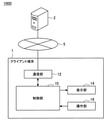
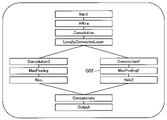
図1は、ニューラルネットワークによる認識処理を複数のハードウェアで実行する例を説明するための説明図である。図1に示すニューラルネットワークにおいて、入力レイヤー(Input layer)と出力レイヤー(Output layer)の間には処理P1~P3が存在する。上記の処理P1~P3が、それぞれ異なるハードウェアで実行されてもよく、例えば、それぞれニューロチップ、CPU、及びGPUで実行されてもよい。例えば、CPUは消費電力が大きく、GPUは消費電力が小さい場合、処理とハードウェアの組み合わせに応じて、パフォーマンスが異なり得る。 FIG. 1 is an explanatory diagram for explaining an example in which recognition processing by a neural network is executed by a plurality of hardware. In the neural network shown in FIG. 1, processes P1 to P3 exist between the input layer and the output layer. The above processes P1 to P3 may be executed by different hardware, and may be executed by, for example, a neurochip, a CPU, and a GPU, respectively. For example, when the CPU consumes a large amount of power and the GPU consumes a small amount of power, the performance may differ depending on the combination of processing and hardware.
しかし、単一のハードウェアで認識処理が実行されることを前提としたニューラルネットワークの設計ツールを用いて、複数のハードウェアで実行されるニューラルネットワークの設計を行うことは困難であった。また、複数のハードウェアで実行されるニューラルネットを設計できたとしても、それぞれのハードウェアには、制約が存在し得るため、例えば設計されたニューラルネットワークが、当該複数のハードウェアの実行に適合しない恐れがあった。例えば、ハードウェアによっては、処理可能なノード数に制約が存在する場合があり、当該ノード数以上のノード数を有するレイヤーが当該ハードウェアに割り当てられてしまうと、認識処理を実行することができない恐れがあった。 However, it has been difficult to design a neural network that is executed by a plurality of hardware by using a neural network design tool that assumes that the recognition process is executed by a single hardware. Also, even if a neural network that can be executed by multiple hardware can be designed, there may be restrictions on each hardware, so for example, the designed neural network is suitable for the execution of the plurality of hardware. I was afraid not to. For example, depending on the hardware, there may be a limit on the number of nodes that can be processed, and if a layer with more nodes than the number of nodes is assigned to the hardware, the recognition process cannot be executed. I was afraid.
そこで、上記事情を一着眼点にして本実施形態を創作するに至った。本実施形態は、複数のハードウェアに係る制約に基づき、ニューラルネットワークが当該制約を満たすか否かを判定し、例えばユーザに判定結果に基づく警告を提供する。本実施形態によれば、複数のハードウェアによる処理に適合したニューラルネットワークをより効率的に設計することが可能である。以下、上記のような効果を実現するための本開示の第一の実施形態の構成例について説明する。 Therefore, the present embodiment was created with the above circumstances as the first point of view. The present embodiment determines whether or not the neural network satisfies the constraint based on the constraint relating to a plurality of hardware, and provides, for example, a warning to the user based on the determination result. According to this embodiment, it is possible to more efficiently design a neural network suitable for processing by a plurality of hardware. Hereinafter, a configuration example of the first embodiment of the present disclosure for realizing the above effects will be described.
<1-2.構成例>
図2を参照しながら、本開示の第一の実施形態の構成例を説明する。図2は、本開示の第一の実施形態に係る情報処理システムの構成例を説明するための説明図である。本実施形態に係る情報処理システム1000は、ユーザによるニューラルネットワークの設計のための情報処理システムであり、例えばビジュアルプログラミングにより、ニューラルネットワークを設計することが可能なツールを提供してもよい。<1-2. Configuration example>
A configuration example of the first embodiment of the present disclosure will be described with reference to FIG. FIG. 2 is an explanatory diagram for explaining a configuration example of the information processing system according to the first embodiment of the present disclosure. The
本開示において、ビジュアルプログラミングとは、ソフトウェア開発において、プログラムコードをテキストで記述することなく、視覚的なオブジェクトを用いて作成する手法を指す。ビジュアルプログラミングでは、例えば、GUI(Graphical User Interface)上で、オブジェクトを操作することで、プログラムを作成することができる。 In the present disclosure, visual programming refers to a method of creating a program code using a visual object without writing it in text in software development. In visual programming, for example, a program can be created by manipulating an object on a GUI (Graphical User Interface).
図2に示すように、本実施形態に係る情報処理システム1000は、クライアント端末1、サーバ2、及び通信網5を含み、クライアント端末1とサーバ2とは、通信網5を介して互いに通信を行えるように接続される。
As shown in FIG. 2, the
クライアント端末1は、ユーザがニューラルネットワークの設計を行うための情報処理装置である。例えば、クライアント端末1は、ビジュアルプログラミングによりニューラルネットワークの設計を行うための設計画面をユーザに提示(表示)してもよい。また、クライアント端末1は、サーバ2からニューラルネットワークが複数のハードウェアに係る制約を満たすか否かの判定結果を受信し、当該判定結果に基づいて、表示制御処理を行ってもよい。
The
サーバ2は、クライアント端末1にニューラルネットワークの設計を行うための設計画面を提供し、クライアント端末1を介したユーザの入力に基づいて、ニューラルネットワークに係るプログラムを作成する情報処理装置である。また、サーバ2は、複数のハードウェアに係る制約に基づいて、ニューラルネットワークが当該制約を満たすか否か判定を行い、判定結果をクライアント端末1に提供する。また、ニューラルネットワークが当該制約を満たさない場合、サーバ2は当該ニューラルネットワークに係るプログラムを作成しなくてもよい。
The
通信網5は、通信網5に接続されている装置、またはシステムから送信される情報の有線、または無線の伝送路である。例えば、通信網5は、インターネット、電話回線網、衛星通信網等の公衆回線網や、Ethernet(登録商標)を含む各種のLAN(Local Area Network)、WAN(Wide Area Network)等を含んでもよい。また、通信網5は、IP-VPN(Internet Protocol-Virtual Private Network)等の専用回線網を含んでもよい。
The
本実施形態に係る情報処理システム1000によれば、ユーザにより設計されるニューラルネットワークが、複数のハードウェアに係る制約を満たすか否かの判定が行われ、判定結果がユーザに提供される。また、本実施形態に係る情報処理システム1000によれば、複数のハードウェアに係る制約を満たすニューラルネットワークに係るプログラムが作成されるようなニューラルネットワークの設計ツールが提供される。
According to the
(クライアント端末)
続いて、本実施形態に係るクライアント端末1について詳細に説明する。図2に示すように、本実施形態に係るクライアント端末1は、制御部10、通信部12、表示部14、及び操作部16を備える情報処理装置である。なお、クライアント端末1は、例えばPC(Personal Computer)、タブレットPC等であってもよい。(Client terminal)
Subsequently, the
制御部10は、クライアント端末1の各構成を制御する。例えば、制御部10は、通信部12による通信を制御する通信制御部としての機能を有する。係る構成により、通信部12は、例えば各種画面や、ニューラルネットワークが複数のハードウェアに係る制約を満たすか否かの判定結果をサーバ2から受信することが出来る。
The
また、制御部10は、表示部14による表示の制御処理を行う表示制御部としての機能を有する。例えば、制御部10は、各種画面を表示部14に表示させてもよい。図3、図4を参照して、制御部10が表示部14に表示させる画面の例を説明する。
Further, the
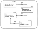
図3は、複数のハードウェアに係る制約を入力するための制約入力画面の一例を示す説明図である。図3に示すように、制約入力画面は、例えば、認識処理に用いられるハードウェアを示すハードウェア入力フォームG11~G14と、ハードウェア間の通信速度を示す通信速度入力フォームG15~G17を含む。ユーザは、ハードウェア入力フォームG11~G14を用いて、ハードウェア(HW:Hardware)の種類(Type)の選択や、ハードウェアの情報(例えば演算性能等)の入力を行うことが可能である。例えば、ハードウェア入力フォームG11~G14によりそれぞれハードウェアHW1~HW4が選択されることで、予め用意された、ハードウェアに係る制約が設定され得る。また、ユーザがハードウェア入力フォームG11~G14を用いて各ハードウェアの情報をさらに入力することで、制約をカスタマイズすることも可能である。 FIG. 3 is an explanatory diagram showing an example of a constraint input screen for inputting constraints relating to a plurality of hardware. As shown in FIG. 3, the constraint input screen includes, for example, hardware input forms G11 to G14 indicating hardware used for recognition processing, and communication speed input forms G15 to G17 indicating communication speed between hardware. The user can select the type (Type) of the hardware (HW: Hardware) and input the hardware information (for example, calculation performance) by using the hardware input forms G11 to G14. For example, by selecting the hardware HW1 to HW4 by the hardware input forms G11 to G14, respectively, the constraints related to the hardware prepared in advance can be set. It is also possible for the user to customize the constraint by further inputting the information of each hardware using the hardware input forms G11 to G14.
また、ユーザは、通信速度入力フォームG15~G17を用いて、ハードウェア間の通信速度の入力(カスタマイズ)を行うことが可能である。なお、ハードウェア入力フォームG11~G14の間の接続関係は、ユーザ操作により変更可能であってもよい。 Further, the user can input (customize) the communication speed between the hardware by using the communication speed input forms G15 to G17. The connection relationship between the hardware input forms G11 to G14 may be changed by a user operation.
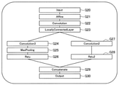
図4は、ニューラルネットワークの設計を行うための設計画面の一例を示す説明図である。図4に示す設計画面は、通信部12を介して、サーバ2から受信されてもよい。図4に示すように、設計画面は、ニューラルネットワークにおける複数のレイヤーG20~G30が配置される。配置されたレイヤーG20~G30は、例えばデータの取り込み、データの処理、データの出力をそれぞれ意味していてもよい。ユーザは、図4に示すような設計画面を用いて、レイヤーの追加、削除、配置変更等を行い、ニューラルネットワークを設計することが出来る。
FIG. 4 is an explanatory diagram showing an example of a design screen for designing a neural network. The design screen shown in FIG. 4 may be received from the
また、入力レイヤーG20と出力レイヤーG30の間のレイヤーG21~G29は、配置された順に逐次、または並列に処理されてもよい。例えば、レイヤーG24~G26の処理と、レイヤーG27~G28の処理とは、並列に処理されてもよい。 Further, the layers G21 to G29 between the input layer G20 and the output layer G30 may be processed sequentially or in parallel in the order in which they are arranged. For example, the processing of layers G24 to G26 and the processing of layers G27 to G28 may be processed in parallel.
また、制御部10(処理部)は、表示部14を制御して、サーバ2から受信される判定結果に基づく表示制御処理を行ってもよい。例えば、サーバ2により、ニューラルネットワークが複数のハードウェアに係る制約を満たさないと判定された場合に、制御部10(表示制御部)は、制約が満たされないことを示す警告画面を表示させてもよい。また、制御部10が表示させる警告画面は、ニューラルネットワークにおいて当該制約を満たさない部分を提示する画面であってもよい。係る構成により、ユーザは複数のハードウェアに係る制約を満たすようにニューラルネットワークをより効率的に設計することが可能となる。
Further, the control unit 10 (processing unit) may control the
通信部12(受信部)は、制御部10により制御されて、他の装置との間の通信を仲介する通信インタフェースである。通信部12は、任意の無線通信プロトコルまたは有線通信プロトコルをサポートし、例えば図2に示す通信網5を介して他の装置との間の通信接続を確立する。例えば、通信部12はニューラルネットワークの設計を行うための設計画面や、ニューラルネットワークが複数のハードウェアに係る制約を満たすか否かの判定結果をサーバ2から受信する。また、通信部12は、表示部14に表示される各種画面に対するユーザの入力に係る情報をサーバ2に送信させる。
The communication unit 12 (reception unit) is a communication interface controlled by the
表示部14は制御部10に制御されて、各種画面を表示するディスプレイである。例えば、表示部14は、上述した制約入力画面、設計画面、警告画面等を表示してもよい。なお、表示部14は、例えば、CRT(Cathode Ray Tube)ディスプレイ装置、液晶ディスプレイ(LCD:Liquid Crystal Display)装置、OLED(Organic Light Emitting Diode)装置により実現されてもよい。
The
操作部16は、ユーザの入力を受け付け、制御部10に提供する。例えば、ユーザは、操作部16を操作して、複数のハードウェアに係る制約のカスタマイズや、ニューラルネットワークの設計を行うための入力を行ってもよい。なお、操作部16は、例えばマウス、キーボード、タッチパネル、ボタン、スイッチ、視線入力装置、ジェスチャ入力装置、音声入力装置などにより実現されてもよい。
The
(サーバ)
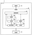
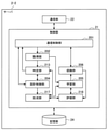
以上、本実施形態に係るクライアント端末1の構成例を説明した。続いて、図5を参照して、本実施形態に係るサーバ2の構成例を説明する。図5は、本実施形態に係るサーバ2の構成例を説明するための説明図である。図5に示すように、サーバ2は、制御部20、通信部22、及び記憶部24を備える情報処理装置である。(server)
The configuration example of the
制御部20は、サーバ2の各構成を制御する。また、制御部20は、図5に示すように、通信制御部201、取得部202、判定部203、設計制御部204、学習部205、及び認識部206としても機能する。
The
通信制御部201は、通信部22による通信を制御する。例えば、通信制御部201は、通信部22を制御して、ニューラルネットワークの設計画面、判定部203による判定結果等を、クライアント端末1に送信させてもよい。また、通信制御部201は、通信部22を制御して、複数のハードウェアに係る制約のカスタマイズや、ニューラルネットワークの設計を行うためのユーザの入力に係る情報を受信してもよい。
The
取得部202は、複数のハードウェアに係る制約を取得する。例えば、取得部202は、記憶部24から、複数のハードウェアに係る制約を取得してもよい。また、取得部202は、通信部22を介して受信される複数のハードウェアに係る制約のカスタマイズを行うためのユーザの入力に基づいて、複数のハードウェアに係る制約を取得してもよい。また、取得部202は、ハードウェアの選択に係るユーザの入力と、記憶部24に予め記憶されたハードウェアに係る制約に基づいて、複数のハードウェアに係る制約を取得してもよい。
The
以下では、図1を参照して説明した、ニューロチップ、CPU、及びGPUに係る制約の例について説明を行うが、ハードウェアに係る制約は以下の例に限定されない。 Hereinafter, examples of restrictions relating to the neurochip, the CPU, and the GPU described with reference to FIG. 1 will be described, but the restrictions relating to the hardware are not limited to the following examples.
取得部202により取得される、複数のハードウェアに係る制約は、例えば後述する判定部203による判定に用いられる制約であってもよい。判定に用いられる制約の例としては、ハードウェア間の接続に係る制約や、ハードウェア間の通信速度に係る制約、ハードウェアの処理能力に係る制約等であってもよい。以下に判定部203による判定に用いられる制約の例を示す。
The constraint related to the plurality of hardware acquired by the
・ニューロチップはセンサ(入力レイヤー)に接続される
・ニューロチップが処理可能なノード数は10以下である
・ニューロチップが処理可能なレイヤーはコンボリューションレイヤーのみである
・ニューロチップとCPUとの間の通信速度は所定の速度である
・CPUが利用可能なRAMは所定値以下である
・CPUとGPUとの間の通信速度は所定の速度である
・GPUはニューロチップと直接接続できない-The neurochip is connected to the sensor (input layer) -The number of nodes that the neurochip can process is 10 or less-The layer that the neurochip can process is only the convolution layer-Between the neurochip and the CPU The communication speed of is a predetermined speed ・ The RAM available to the CPU is less than or equal to a predetermined value ・ The communication speed between the CPU and the GPU is a predetermined speed ・ The GPU cannot be directly connected to the neurochip
また、取得部202により取得される、複数のハードウェアに係る制約は、例えば後述する学習部205がハードウェアに応じた学習を行うために用いられる制約であってもよい。学習を行うために用いられる制約の例としては、ハードウェアの特性に係る制約や、演算の種類に係る制約等であってもよい。以下に、学習部205による学習に用いられる制約の例を示す。
Further, the constraint related to the plurality of hardware acquired by the
・ニューロチップのニューロンの特性はスパイキングである
・CPUは整数演算のみ可能(浮動小数点演算不可能)である・ The characteristic of neuron neurons is spiking. ・ The CPU can only perform integer arithmetic (floating point arithmetic is not possible).
判定部203は、ニューラルネットワークが、取得部202により取得される複数のハードウェアに係る制約を満たすか否か判定を行う。判定部203は、例えば、ユーザの入力に基づいて設計制御部204により設計されたニューラルネットワークが、上記制約を満たすか否か判定を行う。
The
なお、判定部203は、予め設定される、またはユーザにより入力される、所定の処理時間にさらに基づき、ニューラルネットワークが、取得部202により取得される複数のハードウェアに係る制約を満たすか否か判定を行ってもよい。係る場合、判定部203は、ニューラルネットワークが取得部202により取得される複数のハードウェアに係る制約を満たし、かつ当該所定の処理時間内に処理が完了すると判定された場合に、制約を満たすと判定してもよい。
The
また、判定部203は、ユーザの入力に基づいて、設計制御部204によりニューラルネットワークが変更された(例えばレイヤーの追加、削除、配置変更等が発生した)場合に、変更後のニューラルネットワークが上記制約を満たすか否か判定を行ってもよい。なお、判定部203は判定結果を通信制御部201と設計制御部204に提供してもよい。
Further, in the
設計制御部204は、通信部22を介して取得されるユーザの入力に基づいて、ニューラルネットワークの設計を制御する。例えば、設計制御部204は、図4を参照して説明した設計画面を生成し、通信部22を介してクライアント端末1に提供してもよい。また、設計制御部204は、ユーザの入力に基づいて、ニューラルネットワークにおけるレイヤーの配置を制御してもよい。
The
また、設計制御部204は、通信部22を介して取得されるユーザの入力に基づいて、ニューラルネットワークにおけるレイヤーと、ハードウェアの対応付けを行う。対応付けに係るユーザの入力は、ニューラルネットワークの設計画面において範囲選択により行われてもよいし、レイヤーの処理順における順番の指定により行われてもよい。
Further, the
また、設計制御部204は、設計制御部204により設計されたニューラルネットワークが、判定部203により、制約を満たすと判定された場合に、当該ニューラルネットワークを構築するプログラムを作成してもよい。係る構成によれば、複数のハードウェアに係る制約を満たし、当該複数のハードウェアにより認識を実行可能なニューラルネットワークを構築するプログラムが生成される。
Further, the
また、設計制御部204は、設計制御部204により設計されたニューラルネットワークが、判定部203により、制約を満たさないと判定された場合に、当該制約を満たすように、ニューラルネットワークの変更に係るレイヤーの再配置を行ってもよい。例えば、設計制御部204は、追加されたレイヤーまたは配置変更されたレイヤーを、当該レイヤーが現在対応付けられているハードウェアから通信可能なハードウェアに再配置してもよい。また、設計制御部204は、再配置後のニューラルネットワークが制約を満たすか否かの判定結果を判定部203から取得して、制約が満たされるまで、再配置を繰り返してもよい。係る構成によれば、より効率的に、複数のハードウェアに係る制約を満たしたニューラルネットワークを設計することが可能となる。
Further, the
学習部205は、設計制御部204により設計されたニューラルネットワークの学習を行う。学習部205は、例えば取得部202により取得される制約に基づいて、ニューラル根とワークにおけるレイヤーごとに、レイヤーに対応付けられたハードウェアに応じた学習を行ってもよい。係る構成によれば、後述する認識部206により行われる認識の実行パフォーマンスが向上し得る。
The
例えば、ニューロチップと対応付けられたレイヤーに係る学習は、当該ニューロチップの特性に応じた学習手法により行われてもよい。ニューロチップの特性に応じた学習手法は限定されないが、例えばニューロチップの特性がスパイキングである場合には、下記非特許文献2に記載される学習手法を用いることも可能である。
For example, the learning related to the layer associated with the neurochip may be performed by a learning method according to the characteristics of the neurochip. The learning method according to the characteristics of the neurochip is not limited, but for example, when the characteristic of the neurochip is spiking, the learning method described in
非特許文献2:O. Peter、外4名、「Real-time classification and sensor fusion with a spiking deep belief network」、2013年, Neuromorphic Engineering 7: 178. Non-Patent Document 2: O. Peter, 4 others, "Real-time classification and sensor fusion with a spiking deep belief network", 2013, Neuromorphic Engineering 7: 178.
また、整数演算のみ可能なハードウェアと対応付けられたレイヤーに係る学習は、整数演算のみで処理可能となるような学習手法により行われてもよい。係る学習手法は限定されないが、例えば下記非特許文献3に記載される学習手法を用いることも可能である。 Further, the learning related to the layer associated with the hardware capable of only integer operation may be performed by a learning method that can be processed only by integer operation. The learning method is not limited, but for example, the learning method described in Non-Patent Document 3 below can be used.
非特許文献3:M. Courbariaux、外2名、「BinaryConnect: Training Deep Neural Networks with binary weights during propagations TensorFlow: Large-Scale Machine Learning on Heterogeneous Distributed Systems」、2015年11月12日、[Online]、[平成28年4月21日検索]、インターネット< http://arxiv.org/pdf/1511.00363.pdf> Non-Patent Document 3: M. Courbariaux, 2 outsiders, "Binary Connect: Training Deep Neural Networks with binary weights during propagations TensorFlow: Large-Scale Machine Learning on Heterogeneous Distributed Systems", November 12, 2015, [Online], [ Searched on April 21, 2016], Internet <http://arxiv.org/pdf/1511.00363.pdf>
また、浮動小数点演算可能なハードウェアと対応付けられたレイヤーに係る学習は、浮動小数点演算を利用可能な多様な学習手法により行われ得る。 Further, learning related to the layer associated with the hardware capable of floating-point arithmetic can be performed by various learning methods that can use floating-point arithmetic.
なお、学習部205は、記憶部24に記憶される学習データに基づいて学習を行ってもよいし、通信部22を介して外部から取得される学習データに基づいて学習を行ってもよい。
The
認識部206は、学習部205による学習に基づき、認識を実行する。認識部206はニューラルネットワークにおけるレイヤーごとに対応付けられたハードウェアで、フィードフォワード計算を行うことで認識を実行してもよい。なお、認識部206は、記憶部24に記憶されるデータに対して認識を行ってもよいし、通信部22を介して外部から取得されるデータに対して認識を行ってもよい。
The
通信部22は、他の装置との間の通信を仲介する通信インタフェースである。通信部22は、任意の無線通信プロトコルまたは有線通信プロトコルをサポートし、例えば図2に示した通信網5を介して他の装置との間の通信接続を確立する。それにより、例えば、サーバ2が通信網5に接続されたクライアント端末1からユーザの入力等を受信し、及びクライアント端末1に設計画面、及び判定部203による判定結果等を送信することが可能となる。
The
記憶部24は、サーバ2の各構成が機能するためのプログラムやパラメータを記憶する。また、記憶部24は、ハードウェアに係る制約、学習データ、認識用のデータ等を記憶してもよい。
The
なお、上記ではサーバ2が学習部205、認識部206を備えて、学習と認識を行う例を説明したが、本実施形態は上記に限定されない。例えば、学習、及び認識は、通信網5に接続される他の装置で行われてもよく、学習、及び認識のそれぞれが異なる装置により行われてもよい。係る場合、取得部202は、通信部22を介して、当該認識を行う装置から、当該認識を行う装置が有する複数のハードウェアに係る制約を取得してもよい。
Although the example in which the
<1-3.動作例>
以上、本実施形態による情報処理システム1000の構成例について説明した。続いて、本実施形態による情報処理システム1000の動作例について、図6~10を参照して説明する。以下では、まず情報処理システム1000の処理フローについて図6、図7を参照して説明した後、本実施形態においてクライアント端末1に表示される画面遷移例について図8~10を参照して説明する。<1-3. Operation example>
The configuration example of the
(処理フロー例1)
図6は、本実施形態による情報処理システム1000の処理フロー例を示すフローチャート図である。図6に示すフローチャートは、本実施形態に係る動作のうち、特にニューラルネットワークの設計に係る処理フローを示す。(Processing flow example 1)
FIG. 6 is a flowchart showing an example of a processing flow of the
まず、ユーザが図3を参照して説明した制約入力画面を用いて、ハードウェアに係る制約を入力し、取得部202が制約を取得する(S1101)。
First, the user inputs the constraint related to the hardware by using the constraint input screen described with reference to FIG. 3, and the
続いて、ユーザにより、ハードウェアとレイヤーの対応に関するハードウェアごとの範囲が設定される(S1102)。なお、ハードウェアごとの範囲の設定は、ニューラルネットワークの設計画面において、表示上の範囲を選択することで行われてもよいし、レイヤーの処理順における順番の指定により行われてもよい。 Subsequently, the user sets a range for each hardware regarding the correspondence between the hardware and the layer (S1102). The range may be set for each hardware by selecting the range on the display on the design screen of the neural network, or by specifying the order in the processing order of the layers.
続いて、ユーザにより、ニューラルネットワークの設計画面を用いたニューラルネットワークの設計が行われる(S1103)。 Subsequently, the user designs the neural network using the neural network design screen (S1103).
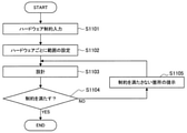
続いて、判定部203により、設計されたニューラルネットワークが、複数のハードウェアに係る制約を満たすか否かの判定が行われる(S1104)。判定部203により、ニューラルネットワークが制約を満たさないと判定された場合(S1104:NO)、制約を満たさない箇所(部分)を提示する警告画面が表示され(S1105)、処理はステップS1103に戻る。一方、判定部203により、ニューラルネットワークが制約を満たすと判定された場合(S1104:YES)、設計処理は終了する。
Subsequently, the
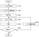
(処理フロー例2)
図7は、本実施形態による情報処理システム1000の処理フロー例を示すフローチャート図である。図7に示すフローチャートは、本実施形態に係る動作のうち、特にニューラルネットワークの設計の変更に係る処理フローを示す。例えば以下に説明する処理フローは、図6に示したフローチャートの処理により設計されたニューラルネットワークの設計を変更する際の処理フローであってもよい。(Processing flow example 2)
FIG. 7 is a flowchart showing an example of a processing flow of the
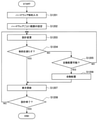
図7に示すステップS1201、S1202の処理は、図6を参照して説明したステップS1101、S1102の処理と同様であるため、説明を省略する。 Since the processing of steps S1201 and S1202 shown in FIG. 7 is the same as the processing of steps S1101 and S1102 described with reference to FIG. 6, the description thereof will be omitted.
続いて、ユーザにより、ニューラルネットワークの設計の変更(例えば、レイヤーの追加、削除、配置変更)が行われる(S1203)。続いて、判定部203により、変更後のニューラルネットワークが、複数のハードウェアに係る制約を満たすか否かの判定が行われる(S1204)。
Subsequently, the user changes the design of the neural network (for example, addition, deletion, and arrangement change of layers) (S1203). Subsequently, the
判定部203により、ニューラルネットワークが制約を満たさないと判定された場合(S1204:NO)、設計制御部204による自動的な再配置が可能であるか否かが判定される(S1205)。自動的な再配置が可能ではない場合(S1205:NO)、処理はステップS1203に戻る。
When the
一方、自動的な再配置が可能である場合、(S1205:NO)、設計制御部204は、自動的に再配置を行う(S1206)。また、自動的な再配置が行われたニューラルネットワークが設計画面に表示される(S1207)
On the other hand, when automatic relocation is possible (S1205: NO), the
また、ステップS1204において制約を満たすと判定された場合、設計が変更されたニューラルネットワークが設計画面に表示される(S1207)。 Further, when it is determined in step S1204 that the constraint is satisfied, the neural network whose design has been changed is displayed on the design screen (S1207).
設計が変更されたニューラルネットワーク、または自動的な再配置が行われたニューラルネットワークを設計画面において確認したユーザにより、設計終了の操作入力が行われると(S1208:YES)、処理は終了する。一方、ユーザが続けて設計の変更行う場合(S1208:NO)、処理はステップS1203に戻る。 When the operation input for the end of the design is performed by the user who confirms the neural network whose design has been changed or the neural network which has been automatically rearranged on the design screen (S1208: YES), the process ends. On the other hand, when the user continuously changes the design (S1208: NO), the process returns to step S1203.
(画面遷移例)
以上、本実施形態による情報処理システム1000の処理フローを説明した。続いて、図7を参照して説明した処理フローにおいて、クライアント端末1に表示される画面の遷移例を図3、4及び図8~10を参照して説明する。図8~10は、本実施形態に係るクライアント端末1に表示される画面例を示す説明図である。なお、図8~10は図4を参照して説明した設計画面に含まれるニューラルネットワークの設計変更に係る画面遷移の一例である。また、以下では、図7に示した処理ステップを適宜参照しながら説明を行う。(Screen transition example)
The processing flow of the
まず、図7のステップS1201において、図3を参照して説明した制約入力画面が表示される。なお、ハードウェアに係る制約をユーザが変更する必要のない場合には、ユーザの入力なしに、取得部202が例えば記憶部24から制約を取得してもよい。
First, in step S1201 of FIG. 7, the constraint input screen described with reference to FIG. 3 is displayed. If the user does not need to change the constraint related to the hardware, the
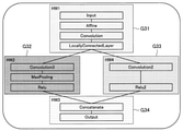
続いて、図7のステップS1202において、図8に示す設計画面のように、ハードウェアごとの範囲選択が行われる。ここで、図8に示す範囲G31~G34に含まれるレイヤーは、設計制御部204により、各範囲に対応するハードウェアと対応付けられる。なお、図8に示す範囲G31、G32、G33、G34は、例えば、それぞれ図3におけるハードウェアHW1、HW2、HW4、HW3に対応している。
Subsequently, in step S1202 of FIG. 7, the range is selected for each hardware as shown in the design screen shown in FIG. Here, the layers included in the ranges G31 to G34 shown in FIG. 8 are associated with the hardware corresponding to each range by the
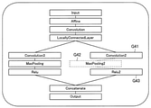
続いて、図7のステップS1203において、図9に示す画面のように、ニューラルネットワークの変更が行われる。図9に示す例では、レイヤーG42がレイヤーG41とレイヤーG43の間に追加されている。なお、図8を参照すれば、図9において新たに追加されるレイヤーG42は、図8に示す範囲G33に含まれるため、HW4に対応付けられる。 Subsequently, in step S1203 of FIG. 7, the neural network is changed as shown in the screen shown in FIG. In the example shown in FIG. 9, layer G42 is added between layers G41 and G43. In addition, referring to FIG. 8, since the layer G42 newly added in FIG. 9 is included in the range G33 shown in FIG. 8, it is associated with HW4.
続いて、図7のステップS1204において、制約を満たすと判定された場合、ステップS1207において、図10に示すように、変更によりレイヤーG52が新たに追加されたニューラルネットワークを含む設計画面が表示される。一方、図7のステップS1204において、制約を満たさないと判定された場合、図4に示した画面のように、変更前のニューラルネットワークを含む設計画面が表示される(表示が図4の設計画面に戻る)。 Subsequently, if it is determined in step S1204 of FIG. 7 that the constraint is satisfied, in step S1207, as shown in FIG. 10, a design screen including a neural network in which the layer G52 is newly added due to the change is displayed. .. On the other hand, if it is determined in step S1204 of FIG. 7 that the constraint is not satisfied, a design screen including the neural network before the change is displayed as shown in FIG. 4 (the display is the design screen of FIG. 4). Return to).
<1-4.効果>
以上説明したように、本開示の第一の実施形態によれば、複数のハードウェアに係る制約に基づき、ニューラルネットワークが当該制約を満たすか否かを判定し、例えばユーザに判定結果に基づく警告画面を提供する。係る構成により、複数のハードウェアによる処理に適合したニューラルネットワークをより効率的に設計することが可能である。また、本実施形態によれば、変更されたニューラルネットワークが当該制約を満たさない場合には、制約を満たすように自動的に再配置が行われることで、制約を満たしたニューラルネットワークの設計を支援することが可能である。<1-4. Effect>
As described above, according to the first embodiment of the present disclosure, it is determined whether or not the neural network satisfies the constraint based on the constraint relating to a plurality of hardware, and for example, a warning based on the determination result is given to the user. Provide a screen. With such a configuration, it is possible to more efficiently design a neural network suitable for processing by a plurality of hardware. Further, according to the present embodiment, when the modified neural network does not satisfy the constraint, the neural network is automatically rearranged so as to satisfy the constraint, thereby supporting the design of the neural network satisfying the constraint. It is possible to do.
<<2.第二の実施形態>>
以上、本開示の第一の実施形態を説明した。続いて、本開示の第二の実施形態を説明する。本開示の第二の実施形態は、設計されたニューラルネットワークの評価結果に基づいて、ネットワーク構造の異なる別のニューラルネットワークを生成する。また、本開示の第二の実施形態は、生成されたニューラルネットワークの評価結果に基づいて、評価済のニューラルネットワークに係るパレート最適解を更新する。さらに、本開示の第二の実施形態は、ネットワークの生成とパレート最適解の更新を繰り返すことで、効率の良いネットワーク構造を探索することが可能である。<< 2. Second embodiment >>
The first embodiment of the present disclosure has been described above. Subsequently, a second embodiment of the present disclosure will be described. The second embodiment of the present disclosure generates another neural network having a different network structure based on the evaluation result of the designed neural network. In addition, the second embodiment of the present disclosure updates the Pareto optimal solution for the evaluated neural network based on the evaluation result of the generated neural network. Further, in the second embodiment of the present disclosure, it is possible to search for an efficient network structure by repeating the generation of the network and the update of the Pareto optimal solution.
以下、上記のような効果を実現するための本開示の第二の実施形態の構成例について説明する。なお、以下の説明においては、第一の実施形態との差異について説明し、第一の実施形態と共通するクライアント端末1、及び通信網5については説明を省略する。
Hereinafter, a configuration example of the second embodiment of the present disclosure for realizing the above effects will be described. In the following description, the differences from the first embodiment will be described, and the description of the
<2-1.構成例>
図11は、本開示の第二の実施形態に係るサーバ2-2の構成例を説明するための説明図である。図11に示すように、サーバ2-2は、制御部21、通信部22、及び記憶部24を備える情報処理装置である。図11に示すように、本実施形態に係るサーバ2―2は、制御部21の機能構成が図5の制御部20の機能構成と一部異なる点で、図5のサーバ2と異なる。なお、図11に示す各構成のうち、図5に示した各構成と実質的に同様の構成については同一の符号を付してあるため、説明を省略する。以下では、本実施形態に係る制御部21が有する判定部213、生成部217、及び評価部218、としての機能について説明する。<2-1. Configuration example>
FIG. 11 is an explanatory diagram for explaining a configuration example of the server 2-2 according to the second embodiment of the present disclosure. As shown in FIG. 11, the server 2-2 is an information processing device including a
本実施形態に係る判定部213は、第一の実施形態で説明した判定部203と同様に、ユーザの入力に基づいて設計制御部204により設計された、または変更されたニューラルネットワークが、取得部202により取得される制約を満たすか否か判定を行う。また、本実施形態に係る判定部213は、後述する生成部217により生成されるニューラルネットワークが、取得部202により取得される制約を満たすか否か判定を行う。
Similar to the
生成部217は、元となるネットワークからネットワーク構造の異なる別のニューラルネットワークを生成する機能を有する。例えば、生成部217は、ユーザによる入力に基づいて設計され、判定部213により制約を満たすと判定されたニューラルネットワーク(以降、シードネットワークとも呼ぶ)から、ネットワーク構造の異なる別のニューラルネットワークを生成してもよい。また、生成部217は、パレート最適解に係るニューラルネットワークから、ネットワーク構造の異なる別のニューラルネットワークを生成してもよい。
The
本実施形態に係る生成部217によるニューラルネットワークの生成は、例えば、突然変異や交叉(または、交差、とも呼ぶ)などを含む遺伝的操作により実現されてもよい。ここで、上記の突然変異とは、生物に見られる遺伝子の突然変異をモデル化したものであってよい。すなわち、本実施形態では、ネットワークを構成する各レイヤーを遺伝子と見立て、レイヤーを突然変異させることで、ネットワーク構造の異なる別のニューラルネットワークを生成することができる。例えば、本実施形態に係る突然変異は、レイヤーの挿入、レイヤーの削除、レイヤー種類の変更、パラメータの変更、グラフ分岐、またはグラフ分岐の削除のうち少なくともいずれか一つを含んでもよい。
The generation of the neural network by the
また、上記の交叉とは、生物の交配における染色体の部分的交換をモデル化したものであってよい。すなわち、本開示に係る情報処理方法では、2つのネットワークのレイヤー構成を部分的に交換することで、上記の別のニューラルネットワークを生成することができる。 Further, the above-mentioned crossover may be a model of partial exchange of chromosomes in the mating of an organism. That is, in the information processing method according to the present disclosure, another neural network described above can be generated by partially exchanging the layer configurations of the two networks.
なお、上記では、遺伝的操作により別のニューラルネットワークを生成する場合を例に説明したが、本実施形態に係るニューラルネットワークの生成方法は、係る例に限定されない。本実施形態に係る別のニューラルネットワークの生成は、例えば、入力されたネットワークのネットワーク構造を変化させるニューラルネットワークを用いて実現されてもよい。ニューラルネットワークの生成には、上記の例を含む種々の方法が適用され得る。 In the above description, a case where another neural network is generated by a genetic operation has been described as an example, but the method for generating a neural network according to the present embodiment is not limited to the above example. The generation of another neural network according to the present embodiment may be realized by using, for example, a neural network that changes the network structure of the input network. Various methods including the above example can be applied to the generation of the neural network.
また、生成部217は、判定部により制約を満たすと判定されたニューラルネットワークが生成されるまで、別のニューラルネットワークの生成を繰り返してもよい。係る構成によれば、生成部217は、複数のハードウェアに係る制約を満たすようなニューラルネットワークを生成することが可能となる。
Further, the
評価部218は、生成されたニューラルネットワークの評価結果を取得する機能を有する。評価部218は、例えば、生成されたニューラルネットワークを認識部206に実行させ、上記の評価結果を取得してもよい。なお、評価部218による評価結果の取得は上記に限定されず、通信網5を介して接続される各種のデバイスに生成されたニューラルネットワークを実行させ、評価結果を取得してもよい。
The
また、評価部218が取得する評価結果には、生成されたニューラルネットワークに係る演算量、及び学習誤差またはヴァリデーション誤差(以下、まとめて誤差と表現することがある)のうち少なくとも一方が含まれてよい。評価部218は、生成されたニューラルネットワークのネットワーク構造に基づいて、上記の演算量を取得することができる。なお、本実施形態に係る評価結果は、上記に限定されず、例えば、ハードウェアに係る使用メモリ量、発熱量、消費電力量、演算量から算出されるハードウェアのトータルコストや、サーバ費用などを含むトータルサービスコスト等を含んでもよい。評価部218は、予め記憶されたハードウェアやサービスに係る情報を基に、上記の値を算出することができる。
Further, the evaluation result acquired by the
また、評価部218は、生成されたニューラルネットワークの評価結果に基づいて、評価済のニューラルネットワークに係るパレート最適解を更新する機能を有する。すなわち、評価部218は、生成部217が生成したニューラルネットワークの評価結果を取得し、当該評価結果に基づいてパレート最適解の更新を繰り返し実行する。
Further, the
<2-2.動作例>
以上、本実施形態に係るサーバ2-2の構成例について説明した。続いて、本実施形態の動作例について、図12~15を参照して説明する。<2-2. Operation example>
The configuration example of the server 2-2 according to the present embodiment has been described above. Subsequently, an operation example of the present embodiment will be described with reference to FIGS. 12 to 15.
図12は、本実施形態の動作例を説明するためのフローチャート図である。図7に示すステップS2100、S2200の処理は、図6を参照して説明したステップS1101、S1102の処理と同様であるため、説明を省略する。 FIG. 12 is a flowchart for explaining an operation example of the present embodiment. Since the processing of steps S2100 and S2200 shown in FIG. 7 is the same as the processing of steps S1101 and S1102 described with reference to FIG. 6, the description thereof will be omitted.
続いて、ユーザによるニューラルネットワークの設計と、判定部213による判定が行われる(S2300)。なお、ステップS2300の処理は、例えば、図6を参照して説明したステップS1103~S1105の処理、または図7を参照して説明したステップS1203~S1208の処理と同様の処理を含んでもよい。
Subsequently, the user designs the neural network and the
続いて、生成部217は、ステップS2300において、判定部213により制約を満たすと判定されたニューラルネットワーク(シードネットワーク)から、ネットワーク構造の異なる別のニューラルネットワークを生成する(S2400)。なお、ステップS2400におけるニューラルネットワークの生成に係る詳細な処理フローについては図13~15を参照して後述する。
Subsequently, the
続いて、評価部218が、生成されたニューラルネットワークの評価結果を取得する(S2500)。評価部218のネットワーク構造の探索が終了していない場合(S2600:NO)、処理はステップS2700に進む。
Subsequently, the
ステップS2700において、評価部218は、生成されたニューラルネットワークの評価結果に基づいて、評価済のニューラルネットワークに係るパレート最適解を更新する。続いて、処理はステップS2400に戻り、生成部217は、当該パレート最適解に係るニューラルネットワークから、ネットワーク構造の異なる別のニューラルネットワークを生成する。
In step S2700, the
上記のステップS2400~S2700の処理により、ニューラルネットワークの生成と、パレート最適解の更新が繰り返し実行されて、ネットワーク構造の探索が終了すると(S2600:YES)、処理は終了する。 By the processing of the above steps S2400 to S2700, the generation of the neural network and the update of the Pareto optimal solution are repeatedly executed, and when the search for the network structure is completed (S2600: YES), the processing is completed.
なお、ネットワーク構造の探索が終了した際、例えば誤差が最小(最高性能)であるニューラルネットワーク、または演算量が最小であるニューラルネットワーク、または中間解であるニューラルネットワークが得られてもよい。中間解の定義は、条件に応じて適宜設計されてよい。なお、上記のようなニューラルネットワークがユーザに提示されて、ユーザがいずれかのニューラルネットワークを選択してもよい。 When the search for the network structure is completed, for example, a neural network having the minimum error (highest performance), a neural network having the minimum calculation amount, or a neural network as an intermediate solution may be obtained. The definition of the intermediate solution may be appropriately designed according to the conditions. A neural network as described above may be presented to the user, and the user may select one of the neural networks.
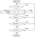
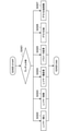
以上、本実施形態の動作例の全体的な処理フローについて説明した。続いて、図12に示すステップS2400のニューラルネットワーク生成に係る処理フローについて、図13を参照して説明する。図13はニューラルネットワーク生成に係る処理フローを説明するためのフローチャート図である。 The overall processing flow of the operation example of this embodiment has been described above. Subsequently, the processing flow related to the neural network generation in step S2400 shown in FIG. 12 will be described with reference to FIG. FIG. 13 is a flowchart for explaining a processing flow related to neural network generation.
図13を参照すると、まず、生成部217は、元となるニューラルネットワークに適用する別のニューラルネットワークの生成方法をランダムで決定する(S2410)。この際、元となるニューラルネットワークは、ユーザによる入力に基づいて設計され、判定部213により制約を満たすと判定されたシードネットワークであってもよい。また、元となるニューラルネットワークは、評価部218が更新したパレート最適解に係るニューラルネットワークから生成部217がランダムに選択したネットワークであってもよい。
Referring to FIG. 13, first, the
続いて、生成部217は、ステップS2410で選択した生成方法に基づいて、元となるニューラルネットワークから、ネットワーク構造の異なる別のニューラルネットワークを生成する。図13に示す一例を参照すると、本実施形態に係る生成部217は、元となるニューラルネットワークを突然変異させることで、上記の別のニューラルネットワークを生成してもよい(S2420)。
Subsequently, the
また、生成部217は、元となるニューラルネットワークを交叉させることで、上記の別のニューラルネットワークを生成してもよい(S2430)。ステップS2420及びステップS2430における突然変異と交叉の詳細な流れについては、それぞれ図14、図15を参照して後述する。
Further, the
続いて、生成部217は、ステップS2420またはステップS2430で生成したニューラルネットワークの整合性を判定する(S2440)。この際、生成部217は、生成したニューラルネットワークのレイヤー構成にエラーが生じているか否かを判定してもよい。生成部217は、例えば、Max-Pooling処理に際し、入力されるデータが小さすぎる場合などに、ネットワークの整合性がない、と判定してよい。このように、生成したニューラルネットワークの整合性がないと判定した場合(S2450:No)、生成部217は、生成したニューラルネットワークを破棄し、ステップS2410に復帰する。
Subsequently, the
一方、生成されたニューラルネットワークに整合性が認められる場合(S2450:Yes)、判定部213が、生成されたニューラルネットワークが、取得部202により取得された制約を満たすか否かを判定する。判定部213が、生成されたニューラルネットワークが制約を満たさないと判定した場合(S2450:NO)、生成部217は、生成したニューラルネットワークを破棄し、ステップS2410に復帰する。
On the other hand, when the generated neural network is consistent (S2450: Yes), the
一方、生成されたニューラルネットワークが制約を満たすと判定した場合、生成部217は、生成したニューラルネットワークと、元となるニューラルネットワークと、の入出力が同一であるか否かを判定する(S2460)。ここで、両者の入出力が異なる場合(S2460:No)、想定する認識問題を処理することが困難となるため、生成部217は、生成したニューラルネットワークを破棄し、ステップS2410に復帰する。一方、生成されたニューラルネットワークと、元となるニューラルネットワークとの入出力が同一である場合(S2460:Yes)、生成部217は、ネットワーク生成に係る処理を正常に終了する。
On the other hand, when it is determined that the generated neural network satisfies the constraint, the
以上、本実施形態に係るニューラルネットワークの生成について説明した。上述したとおり、本実施形態に係る生成部217は、シードネットワークやパレート最適解に係るネットワークから、ネットワーク構造の異なる別のニューラルネットワークを生成することが可能である。なお、図13では、生成部217が突然変異または交叉を用いた遺伝的操作により別のニューラルネットワークを生成する場合を例に説明したが、本実施形態に係るネットワークの生成は係る例に限定されない。本実施形態に係る生成部217は、入力されたニューラルネットワークのネットワーク構造を変化させるニューラルネットワークを用いて、上記の別のニューラルネットワークを生成してもよい。生成部217によるニューラルネットワークの生成には、種々の手法が適用されてよい。
The generation of the neural network according to the present embodiment has been described above. As described above, the
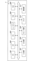
続いて、本実施形態に係る突然変異によるネットワーク生成の流れについて説明する。図14は、生成部217による突然変異を用いたネットワーク生成を説明するためのフローチャートである。すなわち、図14に示すフローチャートは、図13に示したステップS2420における生成部217の詳細な制御を示している。図14を参照すると、本実施形態に係る突然変異は、レイヤーの挿入、レイヤーの削除、レイヤー種類の変更、パラメータの変更、グラフ分岐、グラフ分岐の削除を含んでよい。
Next, the flow of network generation by mutation according to the present embodiment will be described. FIG. 14 is a flowchart for explaining network generation using the mutation by the
図14を参照すると、まず、生成部217は、元となるニューラルネットワークに適用する突然変異の手法をランダムで決定する(S2421)。続いて、生成部217は、ステップS2421で選択した手法に基づいて、元となるニューラルネットワークのネットワーク構造を変化させる。
Referring to FIG. 14, first, the
生成部217は、新規レイヤーを挿入する処理を行ってもよい(S2422)。生成部217は、例えば、元となるニューラルネットワークに、Reluなどの活性化関数を新たに挿入することで、ネットワーク構造の異なる別のニューラルネットワークを生成することができる。
The
また、生成部217は、既存レイヤーを削除する処理を行ってもよい(S2423)。生成部217は、例えば、元となるニューラルネットワークから、Max-Poolingに係るレイヤーを削除することで、ネットワーク構造の異なる別のニューラルネットワークを生成することができる。
Further, the
また、生成部217は、既存レイヤーのレイヤー種類を変更する処理を行ってもよい(S2424)。生成部217は、例えば、元となるニューラルネットワークに存在する活性化関数を別の活性化関数に置換することで、ネットワーク構造の異なる別のニューラルネットワークを生成することができる。
Further, the
また、生成部217は、既存レイヤーに係るパラメータを変更する処理を行ってもよい(S2425)。生成部217は、例えば、既存するConvolutionレイヤーのカーネルシェイプを変更することで、ネットワーク構造の異なる別のニューラルネットワークを生成することができる。
Further, the
また、生成部217は、新たなグラフ分岐を作成する処理を行ってもよい(S2426)。生成部217は、例えば、既存レイヤーの一部をコピーすることでグラフ分岐を作成し、当該グラフ分岐の結合部としてConcatenateレイヤーを挿入することで、別のニューラルネットワークを生成することができる。
Further, the
また、生成部217は、既存のグラフ分岐を削除する処理を行ってもよい(S2427)。生成部217は、例えば、既存するグラフ分岐の1ルートを削除し、当該削除により分岐が消失した場合にはConcatenateレイヤーも削除することで、別のニューラルネットワークを生成することができる。
Further, the
以上、本実施形態に係る生成部217による突然変異を用いたネットワーク生成について説明した。なお、上記では、生成部217がランダムで選択したステップS2422~S2427の処理を実行する場合を例に説明したが、本実施形態に係る突然変異の制御は、係る例に限定されない。生成部217は、ステップS2422~S2427に係る処理を同時に2つ以上行ってもよいし、ステップS2422~S2427の実行判断をそれぞれ実施してもよい。また、生成部217は、図14の例に示した以外の処理を実行してもよい。生成部217による突然変異の制御は、柔軟に変更され得る。
The network generation using the mutation by the
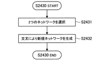
続いて、本実施形態に係る交叉によるネットワーク生成の流れについて説明する。図15は、生成部217による交叉を用いたネットワーク生成を説明するためのフローチャート図である。すなわち、図15に示すフローチャートは、図13に示したステップS2430における生成部217の詳細な制御を示している。
Next, the flow of network generation by crossover according to the present embodiment will be described. FIG. 15 is a flowchart for explaining network generation using crossover by the
図15を参照すると、まず、生成部217は、交叉を実行するために、元となる2つのネットワークを選択する(S2431)。ここで、生成部217は、ユーザによる入力に基づいて設計され、判定部213により制約を満たすと判定された2つのシードネットワークを選択してもよい。また、生成部217は、ユーザによる入力に基づいて設計され、判定部213により制約を満たすと判定された1つのシードネットワークと、予め登録された交叉用のネットワークと、を選択することもできる。さらには、生成部217は、ユーザによる入力に基づいて設計され、判定部213により制約を満たすと判定されたシードネットワークから突然変異により生成した別のニューラルネットワークを選択してもよい。
Referring to FIG. 15, first, the
続いて、生成部217は、ステップS2431で選択した2つのネットワークを交叉させ、ネットワーク構造の異なる別のニューラルネットワークを生成する(S2432)。この際、生成部217は、種々の手法により交叉を実行してよい。生成部217は、例えば、一点交叉、二点交叉、多点交叉、一様交叉などにより、上記の別のニューラルネットワークを生成することができる。
Subsequently, the
以上、本実施形態に係るニューラルネットワークの生成について説明した。上述したとおり、本実施形態に係る生成部217は、突然変異及び交叉を含む遺伝的操作などにより、元となるニューラルネットワークからネットワーク構造の異なる別のニューラルネットワークを生成することができる。すなわち、本実施形態に係る情報処理方法では、生成部217が生成したニューラルネットワークの評価結果に基づいてパレート最適解の更新を繰り返すことで、より効率のよいネットワーク構造を探索することが可能となる。
The generation of the neural network according to the present embodiment has been described above. As described above, the
<2-3.効果>
以上説明したように、本開示の第二の実施形態によれば、設計されたニューラルネットワークの評価結果に基づいて、ネットワーク構造の異なる別のニューラルネットワークを生成することができる。また、本実施形態は、ネットワークの生成と、パレート最適解の更新を繰り返すことで、効率の良いネットワーク構造を探索することが可能である。また、本実施形態において、生成されるニューラルネットワークは、判定部213により、複数のハードウェアに係る制約を満たすと判定されたニューラルネットワークである。したがって、本実施形態によれば、複数のハードウェアによる処理に適合し、かつ効率の良いネットワーク構造を探索することが可能である。<2-3. Effect>
As described above, according to the second embodiment of the present disclosure, another neural network having a different network structure can be generated based on the evaluation result of the designed neural network. Further, in the present embodiment, it is possible to search for an efficient network structure by repeating the generation of the network and the update of the Pareto optimal solution. Further, in the present embodiment, the generated neural network is a neural network determined by the
<<3.変形例>>
以上、本開示の実施形態を説明した。以下では、本開示に係る幾つかの変形例を説明する。なお、以下に説明する各変形例は、単独で各実施形態に適用されてもよいし、組み合わせで各実施形態に適用されてもよい。また、各変形例は、上記実施形態で説明した構成に代えて適用されてもよいし、上記実施形態で説明した構成に対して追加的に適用されてもよい。<< 3. Modification example >>
The embodiments of the present disclosure have been described above. Hereinafter, some modifications according to the present disclosure will be described. In addition, each modification described below may be applied to each embodiment individually or may be applied to each embodiment in combination. Further, each modification may be applied in place of the configuration described in the above embodiment, or may be additionally applied to the configuration described in the above embodiment.
<3-1.変形例1>
上記実施形態ではビジュアルプログラミングによりニューラルネットワークの設計が行われる例を説明したが、本技術は係る例に限定されない。例えば、本技術に係るニューラルネットワークの設計は、テキストによるプログラミングや、CUI(Command User Interface)上の操作により行われてもよい。また、ハードウェアに係る制約や、ハードウェアとレイヤーの対応付けも、上記で説明された例に限定されず、テキスト、またはCUIにより入力されてもよい。<3-1.
In the above embodiment, an example in which the neural network is designed by visual programming has been described, but the present technology is not limited to such an example. For example, the design of the neural network according to the present technology may be performed by programming by text or by operation on the CUI (Command User Interface). Further, the restrictions related to the hardware and the correspondence between the hardware and the layer are not limited to the examples described above, and may be input by text or CUI.
<3-2.変形例2>
また、上記実施形態では、図2、図5、及び図11を参照してクライアント端末1、サーバ2、及びサーバ2-2が有する機能を説明したが、本技術は係る例に限定されない。上記実施形態で説明したクライアント端末1の機能をサーバ2、またはサーバ2-2が有してもよいし、上記実施形態で説明したサーバ2、またはサーバ2-2の機能をクライアント端末1が有してもよい。<3-2.
Further, in the above embodiment, the functions possessed by the
例えば、クライアント端末1が、図5を参照して説明した取得部202、判定部203、及び設計制御部204の機能を有し、クライアント端末1を用いて設計されたニューラルネットワークの情報が、サーバ2に提供されてもよい。
For example, the
<<4.ハードウェア構成例>>
以上、本開示の各実施形態を説明した。上述した表示制御処理、通信制御処理、取得処理、判定処理、設計制御処理、学習処理、認識処理、ネットワーク生成処理、評価結果取得処理等の情報処理は、ソフトウェアと、クライアント端末1、サーバ2、2-2との協働により実現される。以下では、本実施形態に係るサーバ2のハードウェア構成例について説明する。<< 4. Hardware configuration example >>
The embodiments of the present disclosure have been described above. Information processing such as display control processing, communication control processing, acquisition processing, judgment processing, design control processing, learning processing, recognition processing, network generation processing, and evaluation result acquisition processing described above is performed by software,
図16は、サーバ2のハードウェア構成を示した説明図である。図16に示したように、サーバ2は、CPU(Central Processing Unit)2001と、DSP(Digital Signal Pocessor)2002と、GPU(Graphics Processing Unit)2003と、ニューロチップ2004と、ROM(Read Only Memory)2005と、RAM(Random Access Memory)2006と、入力装置2007と、出力装置2008と、ストレージ装置2009と、ドライブ2010と、通信装置2011とを備える。
FIG. 16 is an explanatory diagram showing the hardware configuration of the
CPU2001は、演算処理装置および制御装置として機能し、各種プログラムに従ってサーバ2内の動作全般を制御する。また、CPU2001は、マイクロプロセッサであってもよい。また、DSP2002、GPU2003、ニューロチップ2004は、演算処理装置として機能する。例えば、CPU2001、DSP2002、GPU2003、及びニューロチップ2004は、本開示において、ニューラルネットワークによる認識処理を実行するハードウェアであってもよい。ROM2005は、CPU2001が使用するプログラムや演算パラメータなどを記憶する。RAM2006は、CPU2001、DSP2002、GPU2003、ニューロチップ2004の実行において使用するプログラムや、その実行において適宜変化するパラメータなどを一時記憶する。これらはCPUバスなどから構成されるホストバスにより相互に接続されている。主に、CPU2001、ROM2005及びRAM2006とソフトウェアとの協働により、通信制御部201、取得部202、判定部203、設計制御部204、学習部205の機能が実現される。
The
入力装置2007は、マウス、キーボード、タッチパネル、ボタン、マイクロフォン、スイッチおよびレバーなどユーザが情報を入力するための入力手段と、ユーザによる入力に基づいて入力信号を生成し、CPU2001に出力する入力制御回路などから構成されている。サーバ2のユーザは、該入力装置2007を操作することにより、サーバ2に対して各種のデータを入力したり処理動作を指示したりすることができる。
The
出力装置2008は、例えば、液晶ディスプレイ(LCD)装置、OLED(Organic Light Emitting Diode)装置およびランプなどの表示装置を含む。さらに、出力装置2008は、スピーカおよびヘッドホンなどの音声出力装置を含む。例えば、表示装置は、撮像された画像や生成された画像などを表示する。一方、音声出力装置は、音声データなどを音声に変換して出力する。
The
ストレージ装置2009は、本実施形態にかかるサーバ2の記憶部24の一例として構成されたデータ格納用の装置である。ストレージ装置2009は、記憶媒体、記憶媒体にデータを記録する記録装置、記憶媒体からデータを読み出す読出し装置および記憶媒体に記録されたデータを削除する削除装置などを含んでもよい。このストレージ装置2009は、CPU2001が実行するプログラムや各種データを格納する。
The
ドライブ2010は、記憶媒体用リーダライタであり、サーバ2に内蔵、あるいは外付けされる。ドライブ2010は、装着されている磁気ディスク、光ディスク、光磁気ディスク、または半導体メモリなどのリムーバブル記憶媒体に記録されている情報を読み出して、RAM2005に出力する。また、ドライブ2010は、リムーバブル記憶媒体に情報を書き込むこともできる。
The
通信装置2011は、通信デバイスなどで構成された通信インタフェースである。また、通信装置2011は、無線LAN(Local Area Network)対応通信装置であっても、LTE(Long Term Evolution)対応通信装置であっても、有線による通信を行うワイヤー通信装置であってもよい。通信装置2011は、サーバ2の通信部22に対応する。
The
なお、上記ではサーバ2のハードウェア構成を説明したが、クライアント端末1及び第二の実施形態によるサーバ2-2も、サーバ2と同様に、CPU2001、ROM205およびRAM206などに相当するハードウェアを有する。そして、クライアント端末1のハードウェアとソフトウェアとの協働により例えば制御部10の機能が実現される。また、例えば第二の実施形態によるサーバ2-2、のハードウェアとソフトウェアとの協働により判定部213、生成部217、及び評価部218に相当する機能が実現される。
Although the hardware configuration of the
<<5.むすび>>
以上、説明したように、本開示の実施形態によれば、複数のハードウェアによる処理に適合したニューラルネットワークをより効率的に設計することが可能である。<< 5. Conclusion >>
As described above, according to the embodiment of the present disclosure, it is possible to more efficiently design a neural network suitable for processing by a plurality of hardware.
以上、添付図面を参照しながら本開示の好適な実施形態について詳細に説明したが、本開示の技術的範囲はかかる例に限定されない。本開示の技術分野における通常の知識を有する者であれば、特許請求の範囲に記載された技術的思想の範疇内において、各種の変更例または修正例に想到し得ることは明らかであり、これらについても、当然に本開示の技術的範囲に属するものと了解される。 Although the preferred embodiments of the present disclosure have been described in detail with reference to the accompanying drawings, the technical scope of the present disclosure is not limited to such examples. It is clear that anyone with ordinary knowledge in the art of the present disclosure may come up with various modifications or amendments within the scope of the technical ideas set forth in the claims. Is, of course, understood to belong to the technical scope of the present disclosure.
例えば、上記実施形態における各ステップは、必ずしもフローチャート図として記載された順序に沿って時系列に処理する必要はない。例えば、上記実施形態の処理における各ステップは、フローチャート図として記載した順序と異なる順序で処理されても、並列的に処理されてもよい。例えば、図6において、ハードウェアに係る制約を入力または取得するステップS1101の処理、及びハードウェアごとに範囲を設定するステップS1102の処理は、ニューラルネットワークの設計に係るステップS1103の処理の後に行われてもよい。 For example, each step in the above embodiment does not necessarily have to be processed in chronological order in the order described as a flowchart. For example, each step in the processing of the above embodiment may be processed in an order different from the order described in the flowchart, or may be processed in parallel. For example, in FIG. 6, the process of step S1101 for inputting or acquiring the constraint related to the hardware and the process of step S1102 for setting the range for each hardware are performed after the process of step S1103 related to the design of the neural network. You may.
また、上記実施形態によれば、CPU2001、ROM2005、及びRAM2006等のハードウェアを、上述したクライアント端末1、サーバ2、及びサーバ2-2の各構成と同様の機能を発揮させるためのコンピュータプログラムも提供可能である。また、該コンピュータプログラムが記録された記録媒体も提供される。
Further, according to the above embodiment, there is also a computer program for making hardware such as
また、本明細書に記載された効果は、あくまで説明的または例示的なものであって限定的ではない。つまり、本開示に係る技術は、上記の効果とともに、または上記の効果に代えて、本明細書の記載から当業者には明らかな他の効果を奏しうる。 In addition, the effects described herein are merely explanatory or exemplary and are not limited. That is, the technique according to the present disclosure may exert other effects apparent to those skilled in the art from the description of the present specification, in addition to or in place of the above effects.
なお、以下のような構成も本開示の技術的範囲に属する。
(1)
複数のハードウェアに係る制約を取得する取得部と、
ニューラルネットワークが、前記制約を満たすか否か判定を行う判定部と、
を備える情報処理装置。
(2)
ユーザの入力に基づく前記ニューラルネットワークの設計を制御する設計制御部をさらに備える、前記(1)に記載の情報処理装置。
(3)
前記判定部は、前記設計制御部により前記ニューラルネットワークが変更された場合に、前記判定を行う、前記(2)に記載の情報処理装置。
(4)
前記設計制御部は、前記判定部により、前記制約を満たさないと判定された場合に、前記制約を満たすように、前記変更に係るレイヤーの再配置を行う、前記(3)に記載の情報処理装置。
(5)
前記設計制御部は、前記判定部により、前記制約を満たすと判定された場合に、前記ニューラルネットワークを構築するプログラムを作成する、前記(2)~(4)のいずれか一項に記載の情報処理装置。
(6)
前記判定部により、前記制約を満たさないと判定された場合に、前記制約が満たされないことを示す警告画面を表示させる、表示制御部をさらに備える、前記(1)~(5)のいずれか一項に記載の情報処理装置。
(7)
前記警告画面は、前記ニューラルネットワークにおいて、前記制約を満たない部分を提示する、前記(6)に記載の情報処理装置。
(8)
前記制約に基づいて、前記ニューラルネットワークにおけるレイヤーごとに、前記レイヤーに対応付けられたハードウェアに応じた学習を行う学習部をさらに備える、前記(1)~(7)のいずれか一項に記載の情報処理装置。
(9)
前記判定部により前記制約を満たすと判定されたニューラルネットワークから、ネットワーク構造の異なる別のニューラルネットワークを生成する生成部と、
生成されたニューラルネットワークの評価結果を取得する評価部と、をさらに備え、
前記評価部は、生成されたニューラルネットワークの評価結果に基づいて、評価済のニューラルネットワークに係るパレート最適解を更新し、
前記生成部は、前記パレート最適解に係るニューラルネットワークから、ネットワーク構造の異なる別のニューラルネットワークを生成する、
前記(1)~(8)のいずれか一項に記載の情報処理装置。
(10)
前記判定部は、前記生成部により生成されるニューラルネットワークが、前記制約を満たすか否か判定を行い、
前記生成部は、前記判定部により前記制約を満たすと判定されたニューラルネットワークが生成されるまで、前記別のニューラルネットワークの生成を繰り返す、前記(9)に記載の情報処理装置。
(11)
前記生成部は、遺伝的操作により、前記別のニューラルネットワークを生成する、前記(9)または(10)に記載の情報処理装置。
(12)
前記遺伝的操作は、突然変異または交叉のうち少なくとも一方を含む、前記(11)に記載の情報処理装置。
(13)
前記突然変異は、レイヤーの挿入、レイヤーの削除、レイヤー種類の変更、パラメータの変更、グラフ分岐、またはグラフ分岐の削除のうち少なくともいずれか一つを含む、前記(12)に記載の情報処理装置。
(14)
前記情報処理装置は、前記判定部による判定結果を送信させる通信制御部をさらに備える、前記(1)~(13)のいずれか一項に記載の情報処理装置。
(15)
ニューラルネットワークが複数のハードウェアに係る制約を満たすか否かの判定結果を受信する受信部と、
前記判定結果に基づいて処理を行う処理部と、
を備える情報処理装置。
(16)
複数のハードウェアに係る制約を取得することと、
ニューラルネットワークが、前記制約を満たすか否か判定を行うことと、
を含む情報処理方法。The following configurations also belong to the technical scope of the present disclosure.
(1)
An acquisition unit that acquires constraints related to multiple hardware,
A determination unit that determines whether or not the neural network satisfies the above constraints,
Information processing device equipped with.
(2)
The information processing apparatus according to (1) above, further comprising a design control unit that controls the design of the neural network based on user input.
(3)
The information processing apparatus according to (2), wherein the determination unit makes the determination when the neural network is changed by the design control unit.
(4)
The information processing according to (3) above, wherein the design control unit rearranges the layer related to the change so as to satisfy the constraint when the determination unit determines that the constraint is not satisfied. Device.
(5)
The information according to any one of (2) to (4) above, wherein the design control unit creates a program for constructing the neural network when the determination unit determines that the constraint is satisfied. Processing equipment.
(6)
Any one of (1) to (5) above, further comprising a display control unit that displays a warning screen indicating that the constraint is not satisfied when the determination unit determines that the constraint is not satisfied. The information processing device described in the section.
(7)
The information processing apparatus according to (6), wherein the warning screen presents a portion of the neural network that does not satisfy the restrictions.
(8)
The item according to any one of (1) to (7) above, further comprising a learning unit for learning according to the hardware associated with the layer for each layer in the neural network based on the constraint. Information processing equipment.
(9)
A generation unit that generates another neural network having a different network structure from a neural network determined by the determination unit to satisfy the constraint.
Further equipped with an evaluation unit that acquires the evaluation result of the generated neural network,
The evaluation unit updates the Pareto optimal solution for the evaluated neural network based on the evaluation result of the generated neural network.
The generation unit generates another neural network having a different network structure from the neural network related to the Pareto optimal solution.
The information processing apparatus according to any one of (1) to (8) above.
(10)
The determination unit determines whether or not the neural network generated by the generation unit satisfies the above constraint.
The information processing apparatus according to (9), wherein the generation unit repeats generation of another neural network until a neural network determined to satisfy the constraint is generated by the determination unit.
(11)
The information processing apparatus according to (9) or (10), wherein the generation unit generates another neural network by genetic manipulation.
(12)
11. The information processing apparatus according to (11) above, wherein the genetic manipulation comprises at least one of mutations or crossovers.
(13)
The information processing apparatus according to (12) above, wherein the mutation includes at least one of insertion of a layer, deletion of a layer, change of a layer type, change of parameters, graph branching, or deletion of a graph branch. ..
(14)
The information processing apparatus according to any one of (1) to (13), further comprising a communication control unit for transmitting a determination result by the determination unit.
(15)
A receiver that receives the determination result of whether or not the neural network satisfies the constraints related to multiple hardware, and
A processing unit that performs processing based on the determination result, and
Information processing device equipped with.
(16)
Acquiring constraints for multiple hardware and
Determining whether or not the neural network satisfies the above constraints,
Information processing methods including.
1 クライアント端末
2、2-2 サーバ
5 通信網
10 制御部
12 通信部
14 表示部
16 操作部
20、21 制御部
22 通信部
24 記憶部
201 通信制御部
202 取得部
203、213 判定部
204 設計制御部
205 学習部
206 認識部
217 生成部
218 評価部
1000 情報処理システム1
Claims (8)
前記ニューラルネットワークの設計を制御し、前記判定部により前記制約を満たさないと判定された場合に、前記制約を満たすように、前記ニューラルネットワークにおけるレイヤーの再配置を行う設計制御部と、
を備える情報処理装置。 A determination unit that determines whether or not the neural network satisfies the constraints related to multiple hardware ,
A design control unit that controls the design of the neural network and rearranges layers in the neural network so as to satisfy the constraint when the determination unit determines that the constraint is not satisfied.
Information processing device equipped with.
前記判定部により前記制約を満たさないと判定された場合に、前記ニューラルネットワークにおいて前記制約が満たされない部分を提示する警告画面を表示させる表示制御部と、
を備える情報処理装置。 A determination unit that determines whether or not the neural network satisfies the constraints related to multiple hardware ,
A display control unit that displays a warning screen that presents a portion of the neural network that does not satisfy the constraint when the determination unit determines that the constraint is not satisfied.
Information processing device equipped with.
前記制約に基づいて、前記ニューラルネットワークにおけるレイヤーごとに、前記レイヤーに対応付けられたハードウェアに応じた学習を行う学習部と、
を備える情報処理装置。 A determination unit that determines whether or not the neural network satisfies the constraints related to multiple hardware ,
Based on the constraint, a learning unit that performs learning according to the hardware associated with the layer for each layer in the neural network.
Information processing device equipped with.
前記判定部により前記制約を満たすと判定されたニューラルネットワークから、ネットワーク構造の異なる別のニューラルネットワークを生成する生成部と、
を備え、
前記判定部は、前記生成部により生成されるニューラルネットワークが前記制約を満たすか否か判定を行い、
前記生成部は、前記判定部により前記制約を満たすと判定されるニューラルネットワークが生成されるまで、前記別のニューラルネットワークの生成を繰り返す、
情報処理装置。 A determination unit that determines whether or not the neural network satisfies the constraints related to multiple hardware ,
A generation unit that generates another neural network having a different network structure from a neural network determined by the determination unit to satisfy the constraint.
Equipped with
The determination unit determines whether or not the neural network generated by the generation unit satisfies the above constraint.
The generation unit repeats the generation of another neural network until the determination unit generates a neural network determined to satisfy the constraint.
Information processing equipment.
前記ニューラルネットワークの設計を制御することと、
前記制約を満たさないと判定した場合に、前記制約を満たすように、前記ニューラルネットワークにおけるレイヤーの再配置を行うことと、
を含む情報処理方法。 Determining whether the neural network meets the constraints of multiple hardware ,
Controlling the design of the neural network
When it is determined that the constraint is not satisfied, the layers are rearranged in the neural network so as to satisfy the constraint.
Information processing methods including.
前記制約を満たさないと判定した場合に、前記ニューラルネットワークにおいて前記制約が満たされない部分を提示する警告画面を表示させることと、
を含む情報処理方法。 Determining whether the neural network meets the constraints of multiple hardware ,
When it is determined that the constraint is not satisfied, a warning screen showing a portion of the neural network where the constraint is not satisfied is displayed.
Information processing methods including.
前記制約に基づいて、前記ニューラルネットワークにおけるレイヤーごとに、前記レイヤーに対応付けられたハードウェアに応じた学習を行うことと、
を含む情報処理方法。 Determining whether the neural network meets the constraints of multiple hardware ,
Based on the constraint, learning according to the hardware associated with the layer is performed for each layer in the neural network.
Information processing methods including.
前記制約を満たすと判定したニューラルネットワークから、ネットワーク構造の異なる別のニューラルネットワークを生成することと、
生成したニューラルネットワークが前記制約を満たすか否か判定することと、
前記制約を満たすと判定されるニューラルネットワークが生成されるまで、前記別のニューラルネットワークの生成を繰り返すことと、
を含む情報処理方法。 Determining whether the neural network meets the constraints of multiple hardware ,
To generate another neural network with a different network structure from the neural network determined to satisfy the above constraints,
Determining whether the generated neural network satisfies the above constraints,
Repeating the generation of another neural network until a neural network determined to satisfy the constraint is generated,
Information processing methods including.
Applications Claiming Priority (3)
| Application Number | Priority Date | Filing Date | Title |
|---|---|---|---|
| JP2016091418 | 2016-04-28 | ||
| JP2016091418 | 2016-04-28 | ||
| PCT/JP2017/008988 WO2017187798A1 (en) | 2016-04-28 | 2017-03-07 | Information processing device and information processing method |
Publications (2)
| Publication Number | Publication Date |
|---|---|
| JPWO2017187798A1 JPWO2017187798A1 (en) | 2019-03-07 |
| JP6996497B2 true JP6996497B2 (en) | 2022-01-17 |
Family
ID=60161587
Family Applications (1)
| Application Number | Title | Priority Date | Filing Date |
|---|---|---|---|
| JP2018514172A Active JP6996497B2 (en) | 2016-04-28 | 2017-03-07 | Information processing equipment and information processing method |
Country Status (4)
| Country | Link |
|---|---|
| US (2) | US20190057309A1 (en) |
| EP (1) | EP3451237A4 (en) |
| JP (1) | JP6996497B2 (en) |
| WO (1) | WO2017187798A1 (en) |
Families Citing this family (17)
| Publication number | Priority date | Publication date | Assignee | Title |
|---|---|---|---|---|
| JP6720402B2 (en) * | 2017-03-21 | 2020-07-08 | 株式会社Preferred Networks | Server device, learned model providing program, learned model providing method, and learned model providing system |
| US11270228B2 (en) * | 2017-11-17 | 2022-03-08 | Panasonic Intellectual Property Management Co., Ltd. | Information processing method and information processing system |
| JP7065368B2 (en) * | 2017-11-17 | 2022-05-12 | パナソニックIpマネジメント株式会社 | Information processing method and information processing system |
| EP3770775A4 (en) * | 2018-03-23 | 2021-06-02 | Sony Corporation | INFORMATION PROCESSING DEVICE AND INFORMATION PROCESSING PROCESS |
| EP3779798A4 (en) * | 2018-03-28 | 2021-07-28 | Sony Group Corporation | INFORMATION PROCESSING PROCESS, INFORMATION PROCESSING DEVICE AND PROGRAM |
| WO2019216404A1 (en) * | 2018-05-10 | 2019-11-14 | パナソニックIpマネジメント株式会社 | Neural network construction device, information processing device, neural network construction method, and program |
| US12050991B1 (en) * | 2018-05-21 | 2024-07-30 | Google Llc | Connectomics-based neural architecture search |
| WO2019230254A1 (en) * | 2018-05-31 | 2019-12-05 | ソニー株式会社 | Information processing device, information processing method, and program |
| JP6890741B2 (en) * | 2019-03-15 | 2021-06-18 | 三菱電機株式会社 | Architecture estimator, architecture estimation method, and architecture estimation program |
| JP7111671B2 (en) | 2019-09-05 | 2022-08-02 | 株式会社東芝 | LEARNING APPARATUS, LEARNING SYSTEM AND LEARNING METHOD |
| WO2021079763A1 (en) * | 2019-10-21 | 2021-04-29 | ソニー株式会社 | Information processing method, information processing device, and program |
| CN112884118A (en) * | 2019-11-30 | 2021-06-01 | 华为技术有限公司 | Neural network searching method, device and equipment |
| JP7475164B2 (en) * | 2020-03-05 | 2024-04-26 | キヤノン株式会社 | Information processing device, information processing method, and program |
| TWI900601B (en) * | 2021-01-15 | 2025-10-11 | 美商谷歌有限責任公司 | Computer-implemented method, system, and non-transitory computer readable storage medium for neural architecture scaling for hardware accelerators |
| CN114969636B (en) * | 2021-03-23 | 2023-10-03 | 华为技术有限公司 | Method, device and computer equipment for model recommendation |
| CN113033784A (en) * | 2021-04-18 | 2021-06-25 | 沈阳雅译网络技术有限公司 | Method for searching neural network structure for CPU and GPU equipment |
| CN115438767B (en) * | 2021-06-02 | 2025-12-12 | 杭州海康威视数字技术股份有限公司 | Methods, apparatus, devices and storage media for determining the configuration of neural network models |
Citations (1)
| Publication number | Priority date | Publication date | Assignee | Title |
|---|---|---|---|---|
| US20080319933A1 (en) | 2006-12-08 | 2008-12-25 | Medhat Moussa | Architecture, system and method for artificial neural network implementation |
Family Cites Families (6)
| Publication number | Priority date | Publication date | Assignee | Title |
|---|---|---|---|---|
| JPH03237557A (en) * | 1990-02-14 | 1991-10-23 | Oki Electric Ind Co Ltd | Neural network simulator and computer system |
| US5812993A (en) * | 1996-03-07 | 1998-09-22 | Technion Research And Development Foundation Ltd. | Digital hardware architecture for realizing neural network |
| JPH1091676A (en) * | 1996-07-25 | 1998-04-10 | Toyota Motor Corp | Recording medium storing stabilization design method and stabilization design program |
| US8225074B2 (en) * | 2008-10-02 | 2012-07-17 | Nec Laboratories America, Inc. | Methods and systems for managing computations on a hybrid computing platform including a parallel accelerator |
| CN103678002A (en) * | 2013-12-09 | 2014-03-26 | 华为技术有限公司 | Resource reuse controlling method and device |
| US10769517B2 (en) * | 2016-03-05 | 2020-09-08 | Fujitsu Limited | Neural network analysis |
-
2017
- 2017-03-07 US US16/080,475 patent/US20190057309A1/en active Pending
- 2017-03-07 EP EP17789087.8A patent/EP3451237A4/en not_active Ceased
- 2017-03-07 JP JP2018514172A patent/JP6996497B2/en active Active
- 2017-03-07 WO PCT/JP2017/008988 patent/WO2017187798A1/en not_active Ceased
-
2025
- 2025-09-19 US US19/333,985 patent/US20260017521A1/en active Pending
Patent Citations (1)
| Publication number | Priority date | Publication date | Assignee | Title |
|---|---|---|---|---|
| US20080319933A1 (en) | 2006-12-08 | 2008-12-25 | Medhat Moussa | Architecture, system and method for artificial neural network implementation |
Non-Patent Citations (2)
| Title |
|---|
| JIN, Yaochu ほか,"Neural network regularization and ensembling using multi-objective evolutionary algorithms",Proceedings of the 2004 Congress on Evolutionary Computation,米国,IEEE,2004年06月23日,pp.1-8 |
| 片山 立 ほか,「複数評価基準にもとづくファジィモデルとニューロモデルの総合評価」,日本ファジィ学会誌,日本ファジィ学会,1992年10月31日,第4巻, 第5号,pp.942-957 |
Also Published As
| Publication number | Publication date |
|---|---|
| US20260017521A1 (en) | 2026-01-15 |
| WO2017187798A1 (en) | 2017-11-02 |
| JPWO2017187798A1 (en) | 2019-03-07 |
| US20190057309A1 (en) | 2019-02-21 |
| EP3451237A4 (en) | 2019-04-17 |
| EP3451237A1 (en) | 2019-03-06 |
Similar Documents
| Publication | Publication Date | Title |
|---|---|---|
| JP6996497B2 (en) | Information processing equipment and information processing method | |
| JP6852748B2 (en) | Information processing method and information processing equipment | |
| TWI453628B (en) | Method for adaptively adjusting size of virtual keys and display device usnig the same | |
| CN110968943A (en) | Display method and device of terminal interface | |
| KR102549980B1 (en) | Apparatus and method for providing model for arrangement of object of interior service based on reinforcement learning | |
| JP2022164534A5 (en) | ||
| JP2019046422A (en) | Learning control system and learning control method | |
| KR102592108B1 (en) | System, apparatus, method and program for providing performance production simulation using dynamic light emission pattern | |
| Engert et al. | STRAIDE: a research platform for shape-changing spatial displays based on actuated strings | |
| KR101416916B1 (en) | Optimization distribution system of items in military logistics based on multi agent system and control method of the same | |
| KR102601286B1 (en) | Lighting control device, method and program | |
| CN108108430B (en) | A method for realizing virtual reality system based on Unity3D knowledge forest | |
| JP2015170009A (en) | Display information generation device, program execution situation display system, method and program | |
| JP7279705B2 (en) | Information processing method, information processing device, and program | |
| JP6314717B2 (en) | Ladder program creation device, monitoring device, computer program and device control device | |
| JP2007310860A (en) | Learning apparatus and method | |
| WO2021079763A1 (en) | Information processing method, information processing device, and program | |
| CN112817683A (en) | Control method, control device and medium for topological structure configuration interface | |
| US12572532B2 (en) | Techniques for ontology query construction | |
| EP3822769B1 (en) | Method for editing continual vertical line of visual programming language | |
| JPWO2019064461A1 (en) | Learning network generation device and learning network generation program | |
| MIRRA et al. | A Reinforcement Learning Agent for Enhancing the Reuse of Structural Components in New Buildings | |
| WO2022101467A1 (en) | Method and system for determining optimal outcome in a dynamic environment | |
| CN119473262A (en) | AI graphical programming platform and method based on unsupervised learning | |
| WO2025068749A1 (en) | Manipulating a selection of objects of a digital industrial scene |
Legal Events
| Date | Code | Title | Description |
|---|---|---|---|
| RD04 | Notification of resignation of power of attorney |
Free format text: JAPANESE INTERMEDIATE CODE: A7424 Effective date: 20190208 |
|
| RD03 | Notification of appointment of power of attorney |
Free format text: JAPANESE INTERMEDIATE CODE: A7423 Effective date: 20190214 |
|
| RD04 | Notification of resignation of power of attorney |
Free format text: JAPANESE INTERMEDIATE CODE: A7424 Effective date: 20190222 |
|
| RD02 | Notification of acceptance of power of attorney |
Free format text: JAPANESE INTERMEDIATE CODE: A7422 Effective date: 20190515 |
|
| RD04 | Notification of resignation of power of attorney |
Free format text: JAPANESE INTERMEDIATE CODE: A7424 Effective date: 20190522 |
|
| A521 | Request for written amendment filed |
Free format text: JAPANESE INTERMEDIATE CODE: A523 Effective date: 20200217 |
|
| A621 | Written request for application examination |
Free format text: JAPANESE INTERMEDIATE CODE: A621 Effective date: 20200217 |
|
| A131 | Notification of reasons for refusal |
Free format text: JAPANESE INTERMEDIATE CODE: A131 Effective date: 20210420 |
|
| A521 | Request for written amendment filed |
Free format text: JAPANESE INTERMEDIATE CODE: A523 Effective date: 20210618 |
|
| TRDD | Decision of grant or rejection written | ||
| A01 | Written decision to grant a patent or to grant a registration (utility model) |
Free format text: JAPANESE INTERMEDIATE CODE: A01 Effective date: 20211116 |
|
| A61 | First payment of annual fees (during grant procedure) |
Free format text: JAPANESE INTERMEDIATE CODE: A61 Effective date: 20211129 |
|
| R151 | Written notification of patent or utility model registration |
Ref document number: 6996497 Country of ref document: JP Free format text: JAPANESE INTERMEDIATE CODE: R151 |