JP6996496B2 - LOS-MIMO demodulation device, communication device, LOS-MIMO transmission system, LOS-MIMO demodulation method and program - Google Patents
LOS-MIMO demodulation device, communication device, LOS-MIMO transmission system, LOS-MIMO demodulation method and program Download PDFInfo
- Publication number
- JP6996496B2 JP6996496B2 JP2018513185A JP2018513185A JP6996496B2 JP 6996496 B2 JP6996496 B2 JP 6996496B2 JP 2018513185 A JP2018513185 A JP 2018513185A JP 2018513185 A JP2018513185 A JP 2018513185A JP 6996496 B2 JP6996496 B2 JP 6996496B2
- Authority
- JP
- Japan
- Prior art keywords
- phase
- los
- phase noise
- mimo
- signal
- Prior art date
- Legal status (The legal status is an assumption and is not a legal conclusion. Google has not performed a legal analysis and makes no representation as to the accuracy of the status listed.)
- Active
Links
Images

Classifications
-
- H—ELECTRICITY
- H04—ELECTRIC COMMUNICATION TECHNIQUE
- H04B—TRANSMISSION
- H04B7/00—Radio transmission systems, i.e. using radiation field
- H04B7/02—Diversity systems; Multi-antenna system, i.e. transmission or reception using multiple antennas
- H04B7/04—Diversity systems; Multi-antenna system, i.e. transmission or reception using multiple antennas using two or more spaced independent antennas
- H04B7/0413—MIMO systems
-
- H—ELECTRICITY
- H04—ELECTRIC COMMUNICATION TECHNIQUE
- H04B—TRANSMISSION
- H04B7/00—Radio transmission systems, i.e. using radiation field
- H04B7/005—Control of transmission; Equalising
-
- H—ELECTRICITY
- H04—ELECTRIC COMMUNICATION TECHNIQUE
- H04B—TRANSMISSION
- H04B7/00—Radio transmission systems, i.e. using radiation field
- H04B7/02—Diversity systems; Multi-antenna system, i.e. transmission or reception using multiple antennas
- H04B7/04—Diversity systems; Multi-antenna system, i.e. transmission or reception using multiple antennas using two or more spaced independent antennas
- H04B7/08—Diversity systems; Multi-antenna system, i.e. transmission or reception using multiple antennas using two or more spaced independent antennas at the receiving station
- H04B7/0837—Diversity systems; Multi-antenna system, i.e. transmission or reception using multiple antennas using two or more spaced independent antennas at the receiving station using pre-detection combining
- H04B7/0842—Weighted combining
- H04B7/0848—Joint weighting
- H04B7/0854—Joint weighting using error minimizing algorithms, e.g. minimum mean squared error [MMSE], "cross-correlation" or matrix inversion
-
- H—ELECTRICITY
- H04—ELECTRIC COMMUNICATION TECHNIQUE
- H04L—TRANSMISSION OF DIGITAL INFORMATION, e.g. TELEGRAPHIC COMMUNICATION
- H04L25/00—Baseband systems
- H04L25/02—Details ; arrangements for supplying electrical power along data transmission lines
- H04L25/03—Shaping networks in transmitter or receiver, e.g. adaptive shaping networks
- H04L25/03006—Arrangements for removing intersymbol interference
- H04L25/03159—Arrangements for removing intersymbol interference operating in the frequency domain
-
- H—ELECTRICITY
- H04—ELECTRIC COMMUNICATION TECHNIQUE
- H04L—TRANSMISSION OF DIGITAL INFORMATION, e.g. TELEGRAPHIC COMMUNICATION
- H04L27/00—Modulated-carrier systems
- H04L27/01—Equalisers
-
- H—ELECTRICITY
- H04—ELECTRIC COMMUNICATION TECHNIQUE
- H04L—TRANSMISSION OF DIGITAL INFORMATION, e.g. TELEGRAPHIC COMMUNICATION
- H04L27/00—Modulated-carrier systems
- H04L27/26—Systems using multi-frequency codes
- H04L27/2601—Multicarrier modulation systems
- H04L27/2647—Arrangements specific to the receiver only
- H04L27/2655—Synchronisation arrangements
- H04L27/2657—Carrier synchronisation
- H04L27/266—Fine or fractional frequency offset determination and synchronisation
-
- H—ELECTRICITY
- H04—ELECTRIC COMMUNICATION TECHNIQUE
- H04L—TRANSMISSION OF DIGITAL INFORMATION, e.g. TELEGRAPHIC COMMUNICATION
- H04L27/00—Modulated-carrier systems
- H04L27/32—Carrier systems characterised by combinations of two or more of the types covered by groups H04L27/02, H04L27/10, H04L27/18 or H04L27/26
- H04L27/34—Amplitude- and phase-modulated carrier systems, e.g. quadrature-amplitude modulated carrier systems
- H04L27/38—Demodulator circuits; Receiver circuits
-
- H—ELECTRICITY
- H04—ELECTRIC COMMUNICATION TECHNIQUE
- H04L—TRANSMISSION OF DIGITAL INFORMATION, e.g. TELEGRAPHIC COMMUNICATION
- H04L27/00—Modulated-carrier systems
- H04L27/26—Systems using multi-frequency codes
- H04L27/2601—Multicarrier modulation systems
- H04L27/2647—Arrangements specific to the receiver only
Landscapes
- Engineering & Computer Science (AREA)
- Computer Networks & Wireless Communication (AREA)
- Signal Processing (AREA)
- Physics & Mathematics (AREA)
- Mathematical Physics (AREA)
- Power Engineering (AREA)
- Radio Transmission System (AREA)
Description
(関連出願についての記載)
本発明は、日本国特許出願:特願2016-083552号(2016年4月19日出願)の優先権主張に基づくものであり、同出願の全記載内容は引用をもって本書に組み込み記載されているものとする。
本発明は、多入力多出力(MIMO;Multiple-Input Multiple-Output)無線通信システムに用いる復調装置、通信装置、LOS-MIMO伝送システム、LOS-MIMO復調方法及びプログラムに関し、特に、マイクロ波帯及びミリ波帯を用いた見通し内(LOS;Line-Of-Sight)MIMO無線通信システムに用いる復調装置、通信装置、LOS-MIMO伝送システム、LOS-MIMO復調方法及びプログラムに関する。(Description of related applications)
The present invention is based on the priority claim of Japanese patent application: Japanese Patent Application No. 2016-083552 (filed on April 19, 2016), and all the contents of the application are incorporated in this document by citation. It shall be.
The present invention relates to a demodulator, a communication device, a LOS-MIMO transmission system, a LOS-MIMO demodulator and a program used in a multi-input, multi-output (MIMO) wireless communication system, particularly in the microwave band and. It relates to a demodulator, a communication device, a LOS-MIMO transmission system, a LOS-MIMO demodulator method and a program used in a line-of-sight (LOS; Line-Of-Sigit) MIMO wireless communication system using a millimeter wave band.
近年、送受信局が物理的に固定された見通し内通信システムであるマイクロ波・ミリ波通信システムは、モバイル通信インフラストラクチャとしての需要が飛躍的に増加している。このため、モバイル通信のトラフィックの増大に伴い、更なる伝送容量の大容量化が求められている。このような要求に応じて、偏波多重の利用、変調多値数の増加、あるいは帯域幅の拡大によって伝送容量を増加する手段が知られているが、これらの手段を駆使しても、今後予想されるトラフィック増大には十分とは言えず、これらに加えて更に通信容量の増大を可能とする技術の開発が期待されている。 In recent years, the demand for microwave / millimeter-wave communication systems, which are in-line communication systems in which transmission / reception stations are physically fixed, has dramatically increased as a mobile communication infrastructure. Therefore, as the traffic of mobile communication increases, it is required to further increase the transmission capacity. In response to such demands, means for increasing the transmission capacity by using polarization multiplexing, increasing the number of modulation multi-values, or expanding the bandwidth are known, but even if these means are used in the future, It cannot be said that it is sufficient for the expected increase in traffic, and in addition to these, the development of technology that enables further increase in communication capacity is expected.
そのような技術として、複数の送信・受信アンテナを使用したMIMO伝送システムに注目が集まっている。この技術はこれまで携帯電話、あるいは無線LAN(Local Area Network)等、見通し外の移動体通信システムへの応用を中心に発展してきたが、最近では、マイクロ波及びミリ波を用いた見通し内固定無線通信システムへの適用が検討されており、トラフィックの増大に伴うさらなる大容量化への要請に応える技術として注目されている。 As such a technique, a MIMO transmission system using a plurality of transmitting / receiving antennas is attracting attention. This technology has been developed mainly for applications to non-line-of-sight mobile communication systems such as mobile phones and wireless LAN (Local Area Network), but recently, it has been fixed within the line-of-sight using microwaves and millimeter waves. It is being considered for application to wireless communication systems, and is attracting attention as a technology that responds to the demand for even larger capacities as traffic increases.
見通し内固定無線通信におけるMIMO(以下LOS-MIMOと呼称)伝送の原理については非特許文献1に開示されている。非特許文献1及び非特許文献2では、複数の送信アンテナと受信アンテナを適切に配置することによって伝送遅延の差を調整し、調整された伝送遅延の差によって生じるキャリアの位相回転量が信号対雑音比の向上に貢献して、通信容量の増大が可能となることが示されている。例えば送信アンテナと受信アンテナが各2つずつのケースでは、送信アンテナと受信アンテナが1つずつの通常の一入力一出力(SISO;Single-Input Signle-Output)伝送と比較して、2倍の通信容量が見込める。このような見通し内MIMO通信は、電波の反射、回折、錯乱により、多数の信号が重なり合って時間的に変動する多重伝送波を積極的かつ効果的に利用した、移動体通信や無線LAN等における見通し外MIMO(以下NLOS-MIMOと呼称)通信とは区別される。
Non-Patent
非特許文献3においては、送受信アンテナ数が各々二つずつの2x2 LOS-MIMOに関する信号分離手段を、フェージングによる符号間干渉を補償する時間領域等化器と一体化したLOS-MIMO復調方法が提供されている。 Non-Patent Document 3 provides a LOS-MIMO demodulation method in which a signal separation means relating to 2x2 LOS-MIMO having two transmitting and receiving antennas is integrated with a time domain equalizer that compensates for intersymbol interference due to fading. Has been done.
特許文献1及び2には、マイクロ波帯又はミリ波帯を利用した見通し内固定無線システムにおけるLOS-MIMO通信の実現手段が示されている。これらの文献では、LOS-MIMO伝送によって多重化された受信信号から所望の信号を分離抽出する手段と、従来の単一送信アンテナ、単一受信アンテナによるSISO伝送における通常の復調手段とがタンデムに配置された構成を採用している。このLOS-MIMOに関する信号分離抽出手段は、LOS-MIMO伝送路モデルを表現するパラメータを、直交するパターンを形成する数シンボルからなるパイロット信号系列を伝送することによって推定し、MIMO伝送路で生じた多重化の逆変換を信号処理によって施す事で実現している。
その他、背景技術を構成する文献として、特許文献3、4を挙げておく。本発明との関係性については、後に説明する。 In addition, Patent Documents 3 and 4 are mentioned as documents constituting the background technology. The relationship with the present invention will be described later.
以下の分析は、本発明によって与えられたものである。
マイクロ波帯又はミリ波帯(以下、マイクロ波とミリ波を特に区別しない場合、「マイクロ波/ミリ波帯」と記す。)を利用した見通し内固定無線通信においては、前記の様に、通信容量増大のため1024値以上の信号多値数を利用した超多値伝送が既に使用されている。従って、さらなる大容量化を達成するためには、LOS-MIMO伝送技術は、このような超多値変調と併用して適用可能である必要がある。ところが、マイクロ波/ミリ波帯固定無線通信においてLOS-MIMO伝送を行う場合、各送信アンテナ(及び受信アンテナ)間隔の制約から、各アンテナに付随する位相雑音はアンテナ毎に独立と仮定するのが自然であり、この独立な位相雑音はLOS-MIMO伝送の通信品質を著しく劣化させるという問題がある。このような位相雑音による劣化に加え、LOS-MIMO伝送における信号の多重化によって生じる干渉、さらにはフェージングによって生じる符号間干渉が受信時の信号品質を劣化させる主な要因となる。The following analysis is given by the present invention.
In the fixed line-of-sight wireless communication using the microwave band or the millimeter wave band (hereinafter, referred to as "microwave / millimeter wave band" when the microwave and the millimeter wave are not particularly distinguished), the communication is as described above. Ultra-multi-value transmission using a signal multi-value number of 1024 values or more has already been used to increase the capacity. Therefore, in order to achieve further increase in capacity, LOS-MIMO transmission technology needs to be applicable in combination with such ultra-multi-value modulation. However, when performing LOS-MIMO transmission in microwave / milliwave band fixed wireless communication, it is assumed that the phase noise associated with each antenna is independent for each antenna due to the limitation of the distance between each transmitting antenna (and receiving antenna). Naturally, this independent phase noise has the problem of significantly degrading the communication quality of LOS-MIMO transmission. In addition to such deterioration due to phase noise, interference caused by signal multiplexing in LOS-MIMO transmission, and intersymbol interference caused by fading are the main factors that deteriorate signal quality at the time of reception.
特許文献1、2の構成において、前述の位相雑音による信号品質の劣化に関する補償を行う場合、前記直交するパターンを形成する既知の数シンボルからなるパイロット信号系列を、より高い頻度で伝送して通信路特性の時間変動に追従する必要がある。しかしながら、これは本来の目的であった通信容量の増大を著しく制限することになり、適切な方法とは言えない。
In the configurations of
非特許文献3の方法によれば、前記の直交するパターンを形成する既知の数シンボルからなるパイロット信号系列を必要とせず、単なる既知の信号からなるパイロット信号系列でよく、干渉除去処理後の誤差信号を使ってLOS-MIMOに関する信号処理と符号間干渉補償のための時間領域等化器のタップ係数を制御することにより復調が行える。位相雑音に関しては、例えば特許文献3の方法を組み合わせることは可能であるが、これはSISO伝送を対象とした技術であって、LOS-MIMO伝送において送受信各アンテナで独立に生じる位相雑音の補償への効果は限定的である。結果として、この方法によってもSISO伝送時と比較して多くの制御信号が必要となる。 According to the method of Non-Patent Document 3, a pilot signal sequence consisting of known number symbols forming the orthogonal pattern is not required, and a pilot signal sequence consisting of mere known signals may be used, and an error after interference elimination processing may be used. Demodulation can be performed by using the signal to control the tap coefficient of the time domain equalizer for signal processing related to LOS-MIMO and intersymbol interference compensation. Regarding phase noise, for example, it is possible to combine the methods of Patent Document 3, but this is a technique for SISO transmission, and compensation for phase noise generated independently at each transmitting and receiving antenna in LOS-MIMO transmission. The effect of is limited. As a result, this method also requires more control signals than during SISO transmission.
また、非特許文献3の方法では、SISO伝送の場合の4倍に相当する時間領域等化器が必要となり、演算量及び装置規模の増大が問題となる。これは送受信アンテナ数を倍にすることによって伝送パス数が4倍になり、符号間干渉だけでなく、MIMO伝送における信号多重化に起因する干渉を除去する必要があることによる。さらに水平・垂直偏波を利用した偏波多重伝送を適用するケースにおいては、等化器の数は16倍となり、実装コストの課題が強調される。 Further, the method of Non-Patent Document 3 requires a time domain equalizer corresponding to four times as much as the case of SISO transmission, and an increase in the amount of calculation and the scale of the device becomes a problem. This is because the number of transmission paths is quadrupled by doubling the number of transmit / receive antennas, and it is necessary to eliminate not only intersymbol interference but also interference caused by signal multiplexing in MIMO transmission. Further, in the case of applying polarization multiplex transmission using horizontal / vertical polarization, the number of equalizers is 16 times, and the problem of mounting cost is emphasized.
一般に、等化器の実装コスト削減には時間領域等化よりも周波数領域等化が有効であることが知られている。マイクロ波帯/ミリ波帯を利用した見通し内固定無線に関しては、シングルキャリア伝送が広く用いられているため、シングルキャリア周波数領域等化を適用することになるが、これにはLOS-MIMO伝送の伝送パス数に応じた量の通信路推定用のトレーニングブロックやサイクリックプレフィックス等の冗長データを導入する必要がある。通信容量低下への影響を抑えるためには、このような冗長データ量を少なくする必要があるが、これは伝送品質に悪影響を与える。シングルキャリア周波数領域等化と位相雑音補償については、例えば特許文献4の方法が知られているが、これはSISO伝送を対象とした技術であって、LOS-MIMO伝送への効果は限定的である。 In general, it is known that frequency domain equalization is more effective than time domain equalization in order to reduce the mounting cost of an equalizer. For fixed line-of-sight radio using microwave band / millimeter wave band, single carrier transmission is widely used, so single carrier frequency region equalization will be applied. For this, LOS-MIMO transmission It is necessary to introduce redundant data such as training blocks and cyclic prefixes for estimating the amount of communication paths according to the number of transmission paths. In order to suppress the influence on the decrease in communication capacity, it is necessary to reduce the amount of such redundant data, but this adversely affects the transmission quality. For example, the method of Patent Document 4 is known for single carrier frequency domain equalization and phase noise compensation, but this is a technique for SISO transmission and its effect on LOS-MIMO transmission is limited. be.
以上のように、マイクロ波/ミリ波帯を利用した見通し内固定無線MIMO伝送においては、信号多重化に起因する干渉除去に加え、フェージングによる符号間干渉の除去、及びアンテナ毎に独立な位相雑音補償の全てを、高精度に、なおかつ伝送容量の低下と実装コストの大幅な増加を伴うことなく、行う必要がある。 As described above, in line-of-sight fixed wireless MIMO transmission using the microwave / millimeter wave band, in addition to the interference elimination caused by signal multiplexing, the elimination of intersymbol interference by fading and the phase noise independent for each antenna. All of the compensation needs to be done with high accuracy and without a decrease in transmission capacity and a significant increase in mounting costs.
マイクロ波帯/ミリ波帯を利用した固定無線システムにおけるLOS-MIMOシングルキャリア伝送において、MIMO伝送による信号多重化に伴う干渉に加え、フェージングによる符号間干渉とアンテナ毎に独立な位相雑音に起因する伝送品質の劣化がある場合、背景技術として挙げたLOS-MIMO復調方法では、これら劣化の補償に要する計算コストの増大、及び制御信号(トレーニング系列、パイロット信号)の増大による通信容量の低下が不可避であり、LOS-MIMO伝送技術導入のメリットが制限される。 In LOS-MIMO single carrier transmission in a fixed wireless system using a microwave band / millimeter wave band, in addition to the interference caused by signal multiplexing due to MIMO transmission, inter-code interference due to fading and phase noise independent for each antenna are caused. When there is deterioration in transmission quality, in the LOS-MIMO demodulation method mentioned as the background technology, it is inevitable that the calculation cost required to compensate for these deteriorations will increase and the communication capacity will decrease due to the increase in control signals (training series, pilot signals). Therefore, the merit of introducing LOS-MIMO transmission technology is limited.
本発明は、アンテナ毎、偏波毎に独立な位相雑音に加え、フェージングによる符号間干渉がある伝送環境下にあっても、LOS-MIMO伝送による大容量かつ高品質なデータ伝送が可能な構成の提供に貢献する復調装置及び復調方法を提供する。 The present invention has a configuration capable of large-capacity and high-quality data transmission by LOS-MIMO transmission even in a transmission environment where there is intersymbol interference due to fading in addition to phase noise independent for each antenna and each polarization. A demodulation device and a demodulation method that contribute to the provision of the above are provided.
第1の視点によれば、見通し内多入力多出力(LOS-MIMO;Line of Sight Multiple Input Multiple Output)により送信されたデータを受信する複数の受信アンテナを備えるLOS-MIMO復調装置が提供される。このLOS-MIMO復調装置は、さらに、前記複数の受信アンテナで受信した受信信号の各々から、送信アンテナ及び前記受信アンテナにおいて生じた位相雑音に関連した第1の位相雑音情報と第2の位相雑音情報を算出する位相雑音推定部を備える。このLOS-MIMO復調装置は、さらに、前記複数の受信アンテナで受信した受信信号の各々の位相を、前記第1の位相雑音情報によって補正する第1の補正部を備える。このLOS-MIMO復調装置は、さらに、前記補正後の受信信号に対し、前記複数の受信アンテナで受信した受信信号の各々から干渉による歪を補償する周波数領域等化処理を行う周波数領域等化部を備える。このLOS-MIMO復調装置は、さらに、離散逆フーリエ変換によって前記周波数領域等化処理後の信号を時間領域に戻した信号の位相を、前記第2の位相雑音情報によって補正する第2の補正部を備える。このLOS-MIMO復調装置は、さらに、前記補正後のデータの復号処理を行う復号処理部を備える。 According to a first aspect, there is provided a LOS-MIMO demodulator comprising a plurality of receiving antennas for receiving data transmitted by line-of-sight multi-input multi-output (LOS-MIMO; Line of Gigabit Input Multiple Output). .. In this LOS-MIMO demodulator, further, from each of the received signals received by the plurality of receiving antennas, the first phase noise information and the second phase noise related to the phase noise generated in the transmitting antenna and the receiving antenna are received. A phase noise estimation unit for calculating information is provided. The LOS-MIMO demodulator further includes a first correction unit that corrects the phase of each of the received signals received by the plurality of receiving antennas by the first phase noise information. In this LOS-MIMO demodulator, a frequency region equalization unit that performs frequency region equalization processing for compensating for distortion due to interference from each of the received signals received by the plurality of receiving antennas with respect to the corrected received signal. To prepare for. This LOS-MIMO demodulator further has a second correction unit that corrects the phase of the signal obtained by returning the signal after the frequency domain equalization process to the time domain by the discrete inverse Fourier transform with the second phase noise information. To prepare for. This LOS-MIMO demodulation device further includes a decoding processing unit that performs decoding processing of the corrected data.
第2の視点によれば、上記したLOS-MIMO復調装置を含む通信装置が提供される。 According to the second viewpoint, a communication device including the above-mentioned LOS-MIMO demodulation device is provided.
第3の視点によれば、上記したLOS-MIMO復調装置で算出された前記第2の位相雑音情報を送信側にフィードバックする機能を有し、送信側が、前記複数の送信アンテナから送信される信号の各々に対し、前記第2の位相雑音情報を使用して位相回転処理を行った後、送信するLOS-MIMO伝送システムが提供される。 According to the third viewpoint, it has a function of feeding back the second phase noise information calculated by the above-mentioned LOS-MIMO demodulator to the transmitting side, and the transmitting side has a signal transmitted from the plurality of transmitting antennas. A LOS-MIMO transmission system for transmitting after performing a phase rotation process using the second phase noise information is provided for each of the above.
第4の視点によれば、見通し内多入力多出力(LOS-MIMO;Line of Sight Multiple Input Multiple Output)を構成するLOS-MIMO復調装置の複数の受信アンテナで受信した受信信号の各々から、前記送信アンテナ及び受信アンテナにおいて生じた位相雑音に関連した第一の位相雑音情報と第二の位相雑音情報を算出するステップと、前記複数の受信アンテナで受信した受信信号の各々の位相を、前記第一の位相雑音情報によって補正するステップと、前記補正後の受信信号の各々を長さNの離散フーリエ変換によって周波数領域に変換した信号を入力とし、前記タップ係数を用いて、受信信号の各々から干渉による歪を補償するための周波数領域等化処理を行うステップと、離散逆フーリエ変換によって前記周波数領域等化処理後の信号を時間領域に戻した信号の位相を、前記第2の位相雑音情報によって補正するステップと、を含むLOS-MIMO復調方法が提供される。本方法は、LOS-MIMO復調装置という、特定の機械に結びつけられている。 According to the fourth viewpoint, from each of the received signals received by the plurality of receiving antennas of the LOS-MIMO demodulator constituting the line-of-sight multi-input multi-output (LOS-MIMO; Line of Sign Multiple Input Multiple Output), the above-mentioned The step of calculating the first phase noise information and the second phase noise information related to the phase noise generated in the transmitting antenna and the receiving antenna, and the phase of each of the received signals received by the plurality of receiving antennas are the first. A step of correcting with one phase noise information and a signal obtained by converting each of the corrected received signals into a frequency region by a discrete Fourier transform of length N are used as inputs, and the tap coefficient is used from each of the received signals. The second phase noise information is the phase of the signal obtained by returning the signal after the frequency region equalization processing to the time region by the step of performing the frequency region equalization processing for compensating the distortion due to interference and the discrete inverse Fourier transformation. Provides a LOS-MIMO demodulation method including, and a correction step. This method is tied to a specific machine called a LOS-MIMO demodulator.
第5の視点によれば、上記したLOS-MIMO復調装置の機能を実現するためのコンピュータプログラムが提供される。なお、このプログラムは、コンピュータが読み取り可能な(非トランジエントな)記憶媒体に記録することができる。即ち、本発明は、コンピュータプログラム製品として具現することも可能である。 According to the fifth viewpoint, a computer program for realizing the function of the above-mentioned LOS-MIMO demodulator is provided. Note that this program can be recorded on a computer-readable (non-transient) storage medium. That is, the present invention can also be embodied as a computer program product.
本発明によれば、アンテナ毎、偏波毎に独立な位相雑音に加え、フェージングによる符号間干渉がある伝送環境下にあっても、LOS-MIMO伝送による大容量かつ高品質なデータ伝送をすることが可能となる。即ち、本発明は、背景技術に示したLOS―MIMO伝送システムを、大容量かつ高品質なデータ伝送をなしうるLOS―MIMO伝送システムへと変換するものとなっている。 According to the present invention, large-capacity and high-quality data transmission by LOS-MIMO transmission is performed even in a transmission environment where there is intersymbol interference due to fading in addition to phase noise independent for each antenna and each polarization. It becomes possible. That is, the present invention converts the LOS-MIMO transmission system shown in the background art into a LOS-MIMO transmission system capable of performing large-capacity and high-quality data transmission.
はじめに本発明の一実施形態の概要について図面を参照して説明する。なお、この概要に付記した図面参照符号は、理解を助けるための一例として各要素に便宜上付記したものであり、本発明を図示の態様に限定することを意図するものではない。また、以下の説明で用いる図面中のブロック間の接続線は、双方向及び単方向の双方を含む。一方向矢印については、主たる信号(データ)の流れを模式的に示すものであり、双方向性を排除するものではない。 First, an outline of one embodiment of the present invention will be described with reference to the drawings. It should be noted that the drawing reference reference numerals added to this outline are added to each element for convenience as an example for assisting understanding, and the present invention is not intended to be limited to the illustrated embodiment. Further, the connection line between blocks in the drawings used in the following description includes both bidirectional and unidirectional. The one-way arrow schematically shows the flow of the main signal (data), and does not exclude bidirectionality.
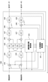
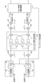
本発明は、その一実施形態において、図1に示すように、LOS-MIMOにより送信されたデータを受信する複数の受信アンテナと、位相雑音推定部12と、第1の補正部11と、前記複数の受信アンテナで受信した受信信号の各々から干渉による歪を補償する周波数領域等化処理を行う周波数領域等化部13と、第2の補正部14と、前記補正後のデータの復号処理を行う復号処理部15と、を備える構成(LOS-MIMO復調装置10)にて実現できる。
In one embodiment of the present invention, as shown in FIG. 1, a plurality of receiving antennas for receiving data transmitted by LOS-MIMO, a phase
より具体的には、位相雑音推定部12は、複数の受信アンテナで受信した受信信号の各々から、送信アンテナ及び前記受信アンテナにおいて生じた位相雑音に関連した第1の位相雑音情報と第2の位相雑音情報を算出する。そして、第1の補正部11は、前記複数の受信アンテナで受信した受信信号の各々の位相を、前記第1の位相雑音情報によって補正する。周波数領域等化部13は、前記補正後の受信信号に対し、前記複数の受信アンテナで受信した受信信号の各々から干渉による歪を補償する周波数領域等化処理を行う。第2の補正部14は、離散逆フーリエ変換によって前記周波数領域等化処理後の信号を時間領域に戻した信号の位相を、前記第2の位相雑音情報によって補正する。
More specifically, the phase
以上のように2段階の補正を行うことで、送受信アンテナ毎に独立に生じた位相雑音の推定を時間領域で行い、周波数領域等化処理によってMIMO伝送による干渉と符号間干渉を除去することができる。このため、LOS-MIMO伝送による大容量かつ高品質なデータ伝送を可能とすることができる。 By performing the two-step correction as described above, the phase noise generated independently for each transmitting / receiving antenna can be estimated in the time domain, and the interference due to MIMO transmission and the intersymbol interference can be removed by the frequency domain equalization processing. can. Therefore, it is possible to transmit large capacity and high quality data by LOS-MIMO transmission.
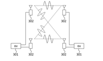
続いて、LOS-MIMO復調装置10のより詳細な構成について、図2、図3を用いて説明する。LOS-MIMO復調装置100は、二つのアンテナから各々独立にデータ列を送信し、二つのアンテナで受信するLOS-MIMO伝送路(図4)において、二つのアンテナによって得られる受信信号から、本来送信した二つの送信データを復元する装置である。
Subsequently, a more detailed configuration of the LOS-
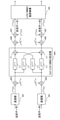
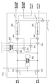
図2に示すように、LOS-MIMO復調装置100は、位相雑音推定部101と、通信路状態推定部102と、位相回転用乗算器103、108と、高速フーリエ変換器(FFT)104と、周波数領域等化器105と、加算器106と、逆高速フーリエ変換器(IFFT)107と、誤り訂正復号部109と、を含む。
As shown in FIG. 2, the LOS-
位相雑音推定部101には、二つの受信アンテナから得られる受信信号1及び受信信号2が入力される。位相雑音推定部101は、前記受信信号1、2と通信路状態推定部102、誤り訂正復号部109の出力情報から、二つの送信アンテナに付随する位相雑音φT
(1)、φT
(2)と、二つの受信アンテナに付随する位相雑音φR
(1),φR
(2)とによって定まる三パターンの位相雑音情報Δ,ψ(1),ψ(2)を推定し、出力する。この位相雑音情報Δ,ψ(1),ψ(2)は、次式によって表される。
![]()
![]()
![]()
![]()
![]()
![]()
以下、Δを第一の位相雑音情報、ψ(1),ψ(2)を第二の位相雑音情報と呼称する。なお、以下、数式中の各項の右上に示すカッコ付きの数字は、送信アンテナ又は受信アンテナの番号によりデータを区別するためのものである。例えば、[数1]からも明らかなとおり、ψ(1)は、第1の送信アンテナに付随する位相雑音φT
(1)が反映され、ψ(2)は、第2の送信アンテナに付随する位相雑音φT
(2)が反映されている。同様に、M本のアンテナやFFT出力の組み合わせを特に区別する場合、(p,p)の形式(但し、p≦Mの整数)でカッコ付きで表示する。なお、上記したカッコを用いた表記に代えて、φT
(1),φT
(2)は、φT1,φT2と表すこともできる。同様に、h(p1,p2)は、hp1p2と表すこともできる。Hereinafter, Δ is referred to as first phase noise information, and ψ (1) and ψ (2) are referred to as second phase noise information. In the following, the numbers in parentheses shown in the upper right of each item in the formula are for distinguishing data by the numbers of the transmitting antenna or the receiving antenna. For example, as is clear from [Equation 1], ψ (1) reflects the phase noise φ T (1) associated with the first transmitting antenna, and ψ (2) is associated with the second transmitting antenna. The phase noise φ T (2) is reflected. Similarly, when the combination of M antennas and FFT outputs is particularly distinguished, it is displayed in parentheses in the format (p, p) (however, an integer of p ≦ M). In addition, instead of the above-mentioned notation using parentheses, φ T (1) and φ T (2) can also be expressed as φ T1 and
位相回転用乗算器103は、前記位相雑音推定部101の出力である第一の位相雑音情報Δによって、受信信号1と受信信号2の位相を回転し、補正する。
The
二つの高速フーリエ変換器(FFT)104は、前記位相回転用乗算器103の出力結果を入力し、その周波数成分をフーリエ変換によって算出して出力する。
The two fast Fourier transformers (FFT) 104 input the output result of the
周波数領域等化器(FDE)105は、通信路状態推定部102から供給される情報を前記高速フーリエ変換器の出力に乗算し、出力する。この周波数領域等化器(FDE)105は、送信受信各二本ずつのアンテナによって構成される四つの伝送パスにおいて生じたフェージングによる符号間干渉を除去する役割を果たす。図2中にあるように、四つの周波数領域等化器(FDE)105の出力データは、二つのペアに分類され、各ペアは加算器106で加算された後、逆高速フーリエ変換器(IFFT)107によって周波数領域から時間領域データに変換される。
The frequency domain equalizer (FDE) 105 multiplies the output of the fast Fourier transform device by the information supplied from the channel
位相回転用乗算器108は、前記逆高速フーリエ変換器107の出力信号の位相を、前記位相雑音推定部101の出力である第二の位相雑音情報ψ(1),ψ(2)に従って回転し、出力する。The
誤り訂正復号部(DEC)109は、前記位相回転用乗算器108の出力信号を入力し、誤り訂正符号の復号処理を行って訂正後のデータを出力する。誤り訂正復号部109の出力はLOS-MIMO復調装置100の出力データとなる。
The error correction decoding unit (DEC) 109 inputs the output signal of the
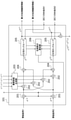
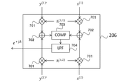
図3は、前記位相雑音推定部101の一実施形態を示したブロック図である。図3を参照すると、位相回転用乗算器201、MIMO干渉除去用乗算器202、乗算係数生成部203、MIMO干渉除去用加算器204、位相ロックループ205、位相差分算出部206を含む構成が示されている。
FIG. 3 is a block diagram showing an embodiment of the phase
二つの受信アンテナから得られる受信信号1及び受信信号2の受信データは、位相回転用乗算器201によって、位相差分算出部206が出力する第一の位相雑音情報Δによって位相補正を施される。乗算器202と加算器204は、前記位相補正後の受信データからMIMO干渉成分を除去する。乗算器202の乗算係数は、乗算係数生成部203より供給される。二つのMIMO干渉除去用加算器204の出力信号y(1),y(2)は、各々位相ロックループ205に入力される。即ち、乗算器202、乗算係数生成部203及び加算器204が、受信信号を重み付けして加算する動作を行うことになる。位相ロックループ205は、残留する位相雑音の推定結果である第二の位相雑音情報ej(Ψ(1)-Ψ(2))を算出し、出力する。The received data of the received
以上の構成によれば、送受信アンテナ毎に独立に生じた位相雑音の推定を時間領域で行い、周波数領域等化処理によってMIMO伝送による干渉と符号間干渉を除去することができる。このため、LOS-MIMO伝送による大容量かつ高品質なデータ伝送を可能とすることができる。 According to the above configuration, the phase noise generated independently for each transmission / reception antenna can be estimated in the time domain, and the interference due to MIMO transmission and the intersymbol interference can be removed by the frequency domain equalization processing. Therefore, it is possible to transmit large capacity and high quality data by LOS-MIMO transmission.
[第1の実施形態]
続いて、本発明の第1の実施形態について図面を参照して詳細に説明する。はじめに、LOS-MIMO復調装置100を含む無線伝送方式について説明する。以下の説明においては、位相情報をデータの識別に使用する変調方式を対象とし、一例として直交振幅変調(QAM:Quadrature Amplitude Modulation)である場合を説明する。[First Embodiment]
Subsequently, the first embodiment of the present invention will be described in detail with reference to the drawings. First, a wireless transmission method including the LOS-
図4は、送信アンテナ数が2、受信アンテナ数が2のLOS-MIMO無線伝送システムの構成を表すブロック図である。図4を参照すると、それぞれ2つの屋外装置302(Out Door Unit;ODU)が接続された屋内装置301(In Door Unit;IDU)間で、屋外装置302のアンテナを用いてデータを送受信する構成が示されている。
FIG. 4 is a block diagram showing a configuration of a LOS-MIMO wireless transmission system having 2 transmitting antennas and 2 receiving antennas. Referring to FIG. 4, there is a configuration in which data is transmitted / received between the indoor devices 301 (In Door Unit; IDU) to which two outdoor devices 302 (Out Door Unit; ODU) are connected by using the antenna of the
図5は、上述の屋内装置301に含まれる変復調処理部と、屋外装置302において生じる雑音源、及びLOS-MIMO伝送路をベースバンド信号処理モデルで表したブロック図であり、送信データとLOS-MIMO復調装置100の入力信号の関係を示している。
FIG. 5 is a block diagram showing a modulation / demodulation processing unit included in the above-mentioned
図5のモデルにおいて、送信側は2つの変調器401と送信側位相雑音源402を含み、LOS-MIMO伝送路は、四つの伝送パスからなるフェージング通信路404とMIMO干渉405によって構成される。受信側は、受信側位相雑音源406、熱雑音源407、及び本発明のLOS-MIMO復調装置100を含む。
In the model of FIG. 5, the transmit side includes two
QAM方式において、信号点数が2m個の場合(mは正整数)、変調器401において、送信データをmビット毎に区切り、mビットを2m個の信号点の一つにマッピングする。マッピングされた信号点は複素数値で表すことができ、従ってベースバンドモデルにおける信号は複素数で表現される。In the QAM method, when the number of signal points is 2 m (m is a positive integer), the transmission data is divided into m bits and the m bits are mapped to one of the 2 m signal points in the
図6は、受信器から送信器へのフィードバック伝送路があるLOS-MIMO伝送のベースバンド信号処理モデルを示す。図5との違いはフィードバック伝送路があることである。図6のベースバンド信号処理モデルでは、LOS-MIMO復調装置100よりフィードバックされた情報を使用して、送信側ではLOS-MIMO伝送路への送信信号に処理を施す。この処理の詳細については後述する。
FIG. 6 shows a baseband signal processing model of LOS-MIMO transmission with a feedback transmission path from the receiver to the transmitter. The difference from FIG. 5 is that there is a feedback transmission line. In the baseband signal processing model of FIG. 6, the information fed back from the LOS-
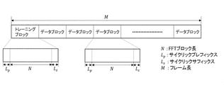
図7は、LOS-MIMO伝送路を通して伝達する信号に関する典型的な信号フォーマットの一例を示す。信号フォーマットは、通信路状態を推定するためのトレーニングブロックとデータブロックからなる。トレーニングブロックとデータブロックは、各々長さNのトレーニング系列、データ系列と、長さLp,Lsのサイクリックプレフィックスとサイクリックサフィックスを含む。ここで、後述のように、Nは高速フーリエ変換のブロック長を表すため2の冪とし、Lp,Lsは0以上の整数とする。以下、LOS-MIMO復調装置100への二つの入力信号は、図7のフォーマットに従うものとして説明する。FIG. 7 shows an example of a typical signal format for a signal transmitted through a LOS-MIMO transmission line. The signal format consists of a training block and a data block for estimating the channel state. The training block and the data block include a training sequence of length N, a data sequence, and a cyclic prefix and a cyclic suffix of length L p , L s , respectively. Here, as described later, N is a power of two to represent the block length of the Fast Fourier Transform, and L p and L s are integers of 0 or more. Hereinafter, the two input signals to the LOS-
以下、再度図1を参照して、LOS-MIMO復調装置100の各部について説明する。LOS-MIMO復調装置100への入力信号のうち、トレーニングブロック部分は、通信路状態推定部102へ入力され、処理される。トレーニングブロック以外のデータブロックについては位相雑音推定部101に入力されると共に、第一の位相雑音情報によって補正を行うための位相回転用乗算器103に入力される。通信路状態推定部102及び位相雑音推定部101の動作については後述する。
Hereinafter, each part of the LOS-
LOS-MIMO復調装置100への入力信号r(1)(n),r(2)(n)は、前記の様に位相回転用乗算器103に入力される。位相回転用乗算器103のもう一方の入力は位相雑音推定部101の出力である第一の位相雑音情報FPNである。第一の位相雑音情報FPNは[数2]によって表される。位相回転用乗算器103は、それぞれr(1)’(n)=e-jΔ(n)r(1)(n),r(2)’(n)=ejΔ(n)r(2)(n)を出力する。その後、前記位相回転用乗算器103の出力r(1)’(n),r(2)’(n)は高速フーリエ変換器(FFT)104に入力される。高速フーリエ変換器(FFT)104の出力R(1)(n),R(2)(n)は、次の[数3]で示される(nは0からN-1の間の整数を表す)。
![]()

![]()
高速フーリエ変換器104の出力は、四つの周波数領域等化器(FDE)105に入力される。周波数領域等化器105は、前記R(1)(n),R(2)(n)と通信路状態推定部102から提供される信号Q(1,1)(n),Q(1,2)(n),Q(2,1)(n),Q(2,2)(n)とを乗算し、出力する。四つの周波数領域等化器105の出力データは、二つのペアに分類され、各ペアは加算器106で加算される。二つの加算器106の出力Y(1)(n),Y(2)(n)は、次の[数4]で表すことができる。
![]()
![]()
![]()
![]()
上記[数3]の出力Y(1)(n),Y(2)(n)は、逆高速フーリエ変換器(IFFT)107に入力される。逆高速フーリエ変換器107は、次の[数5]に示すy(1)(n),y(2)(n)を算出して出力する。

逆高速フーリエ変換器(IFFT)107の出力は、位相回転用乗算器108に入力され、各々位相雑音推定部101の出力である次の[数6]に示す第二の位相雑音情報SPN(1),SPN(2)と乗算される。位相回転用乗算器108の出力信号SPN(1)y(1)(n),SPN(2)y(2)(n)に対し、誤り訂正復号部109において誤り訂正処理を行い、送信データを推定して出力する。誤り訂正復号部の出力は、後述する位相雑音推定部102において、前記第一の位相雑音情報FPNと第二の位相雑音情報SPN(1),SPN(2)に関する計算精度を高める役割を果たすことができる。The output of the inverse fast Fourier transform (IFFT) 107 is input to the
![]()
![]()
次に、位相雑音推定部101の動作について、再度図3を用いて説明する。図5あるいは図6に示したベースバンド信号伝送モデルにおいて、アンテナ1から送信する信号をs(1)(n)、アンテナ2から送信する信号をs(2)(n)と記すと(nは時点を表す整数とする)、対応する受信信号r(1)(n),r(2)(n)は行列表現を使って、次の[数7]で表現できる。
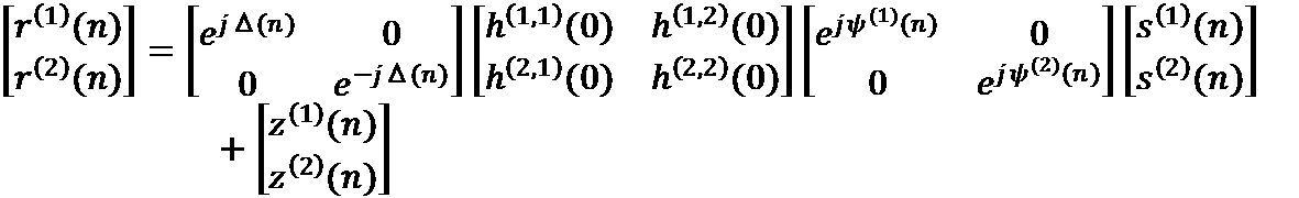
ここで、z(1)(n),z(2)(n)は熱雑音成分を表す。第一の位相雑音情報の指数部Δ(n)及び第二の位相雑音情報の指数部ψ(1)(n),ψ(2)(n)は、送信アンテナ1、2に付随する位相雑音φT
(1)(n),φT
(2)(n)と、受信アンテナ1、2に付随する位相雑音φR
(1)(n),φR
(2)(n)によって、次の[数8]、[数9]で表すことができる。
![]()
![]()
![]()
![]()
![]()
![]()
図3の位相雑音推定部101は、受信信号r(1)(n),r(2)(n)を入力し、前記[数8]、[数9]に示した第一の位相雑音情報の指数部Δ(n)と第二の位相雑音情報の指数部ψ(1)(n),ψ(2)(n)を推定し、出力する。以下、その動作について説明する。The phase
受信信号r(1)(n),r(2)(n)は、位相回転用乗算器201によって、位相差分算出部206の出力情報分の位相回転処理を施される。位相差分算出部206の出力は、後述のように[数8]の第一の位相雑音情報の指数部Δ(n)の推定結果であり、二つの位相回転用乗算器201の出力は、各々e-jΔ(n)r(1)(n),ejΔ(n)r(2)(n)となる。次いで、位相回転用乗算器201の出力は、乗算係数生成部203によって供給される乗算係数と四つの乗算器202によって乗算され、その後、加算器204によって加算される。乗算係数生成部203によって供給される定数は、例えば次の[数10]で表される2×2行列qの四つの成分q(1,1),q(1,2),q(2,1),q(2,2)となる。The received signals r (1) (n), r (2) (n) are subjected to phase rotation processing for the output information of the phase

尚、h(1,1)(0),h(1,2)(0),h(2,1)(0),h(2,2)(0)は通信路状態推定部102より提供される。従って、前記乗算器202と加算器204による演算結果y(1)(n),y(2)(n)は、位相差分算出部206が出力する第一の位相雑音情報の指数部Δ(n)がほとんど誤差を含まない場合、各々y(1)(n)=SPN(1)s(1)(n)+w(1)’(n),y(2)(n)=SPN(2)s(2)(n)+w(2)’(n)となる。ここで、w(1)’(n),w(2)’(n)は熱雑音成分を表す。従ってこの場合、前記加算器204の出力データの各々を位相ロックループ205に入力することによって、SPN(1),SPN(2)を推定することができる。Note that h (1,1) (0), h (1,2) (0), h (2,1) (0), h (2,2) (0) are provided by the communication path
尚、図3中の位相ロックループ205のもう一つの入力は、前記誤り訂正復号部109の出力から供給される。誤り訂正処理後のデータとの比較によって位相誤差を推定することで、位相ロックループの精度向上が期待できるが、これは、より高い精度が要求される場合に対処するための措置であって、必須ではない。誤り訂正復号部の出力結果を利用しない場合には、通常の位相ロックループが行うように、入力信号の硬判定結果との比較から位相誤差を推定することとする。また、図3の位相雑音推定装置は第二の位相雑音情報SPN(1),SPN(2)の他に、その差分値によって定まる[数11]の位相雑音情報PNFEEDBACKを出力するが、これは図5に示したブロック図でモデル化されるLOS-MIMO伝送システムでは使用せず、図6に示したブロック図でモデル化されるようなフィードバック伝送路のあるLOS-MIMO伝送システムにおいて使用する。
![]()
![]()
図6は受信器から送信器へのフィードバック伝送路があるLOS-MIMO伝送のベースバンド信号処理モデルを示す。前記の様に図5との違いはフィードバック伝送路があることであり、フィードバック伝送路は、前記位相雑音推定部101の出力である位相雑音情報PNFEEDBACKを送信側に伝送する。送信側では位相回転用乗算器501を備え、これを用いて前記送信データs(1)(n),s(2)(n)と前記位相雑音情報とを乗算し、各々e-jψ(n)s(1)(n),ejψ(n)s(2)(n)として送信する。FIG. 6 shows a baseband signal processing model of LOS-MIMO transmission with a feedback transmission path from the receiver to the transmitter. As described above, the difference from FIG. 5 is that there is a feedback transmission line, and the feedback transmission line transmits the phase noise information PN FEEDBACK , which is the output of the phase
次に位相差分算出部206の動作について説明する。図8に位相差分算出部206の一実施形態を表すブロック図を示す。図8の位相差分算出部206は、乗算器701、加算器702、位相比較器703、ローパスフィルタ704を含む。前記二つの位相ロックループ内で算出される信号y(1)’=SPN(1)y(1)(n),y(2)’=SPN(2)y(1)(n)及び前記信号y(1)’,y(2)’の各々について最も近い送信信号s(1),s(2)を入力する。これら入力信号は、乗算器701、加算器702を通して、位相比較器703への入力a=y(1)’h(1,1)(0)+y(2)’h(1,2)(0),b=s(1)h(1,1)(0)+s(2)h(1,2)(0)へ変換される。位相比較器703は、前記二つの入力a,bの位相差を出力する。尚、煩雑となることを避けるため、図中での記述を省略したが、h(1,1)(0),h(1,2)(0),h(2,1)(0),h(2,2)(0)は、前記の様に通信路状態推定部102より提供されるものである。位相比較器703の出力は、ローパスフィルタ704によって高周波成分をカットされ、位相差分を表す信号ejΔ(n)として出力される。以上の様に、位相雑音推定部101は、LOS-MIMO復調装置100への入力となる受信信号r(1)(n),r(2)(n)から、第一及び第二の位相雑音情報FPN,SPN(1),SPN(2)を算出し、出力する。Next, the operation of the phase
次に、通信路状態推定部102の動作について説明する。通信路状態推定部102は、図7に示した伝送フレームフォーマットにおける受信データ1のトレーニング系列部分列(rT
(1)(0),rT
(1)(1),・・・,rT
(1)(N-1)と記述)と、受信データ2のトレーニング系列部分列(rT
(2)(0),rT
(2)(1),・・・,rT
(2)(N-1)と記述)とから、長さNの四つの系列(Q(u,v)(0),Q(u,v)(1),・・・,Q(u,v)(N-1);u,vは各々1または2を表す)を算出し、出力する。Next, the operation of the communication path
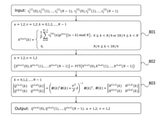
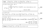
図9は、通信路状態推定部102の機能である通信路状態推定方法の手順を示すフローチャートである。[数12]は、送信アンテナ1から送信されるトレーニング系列p(1)(0),p(1)(1),・・・,p(1)(N-1)及び、送信アンテナ2から送信されるトレーニング系列p(2)(0),p(2)(1),・・・,p(2)(N-1)を示す。
![]()
![]()
![]()
![]()
尚、[数12]において、送信データの平均電力値をPと記した。通信路状態推定部102は、まず図9のフローチャート中の801に示した演算方法に従って(801中の*は複素共役を表す)、長さNの四つの系列h(u,v)(0),h(u,v)(1),・・・,h(u,v)(N-1)を算出する(u,vは各々1または2を表す)。これは、送信したトレーニング信号系列とそれに対応する受信信号の畳込み演算によって定まる長さNの系列のうち、半数のN/2個の信号部分を0にマスクして得られる系列である。即ち、以上の処理が、前記送信アンテナ毎に送信される長さNのトレーニング信号の複素共役からなる信号系列p(v)*と、該トレーニング信号をLOS-MIMO伝送路への送信信号とし等倍でサンプリングした長さNの受信信号rT
(u)とを、畳込み演算して得られる長さNの信号系列において、そのうち半数のN/2個の信号をゼロにマスクした長さNの信号系列を算出する処理に相当する(図9の801参照)。
In [Equation 12], the average power value of the transmission data is described as P. The channel
次に、図9のフローチャート中の802に示したように、通信路状態推定部102は、これら四つの長さNの系列h(u,v)(0),h(u,v)(1),・・・,h(u,v)(N-1)を各々フーリエ変換して、長さNの四つの系列H(u,v)(0),H(u,v)(1),・・・,H(u,v)(N-1)を算出する。Next, as shown in 802 in the flowchart of FIG. 9, the channel
最後に図9のフローチャート中の803に示すように、通信路状態推定部102は、前記四つの系列H(u,v)(0),H(u,v)(1),・・・,H(u,v)(N-1)を処理し、長さNの四つの系列Q(u,v)(0),Q(u,v)(1),・・・,Q(u,v)(N-1)を算出して出力する。Finally, as shown in 803 in the flowchart of FIG. 9, the communication path
尚、H(k)は、前記H(u,v)(k)を(u,v)成分とする行列であって、H(k)^†は行列H(k)の共役転置行列を表す。図9の803に示した処理は、LOS-MIMO伝送路の周波数応答をH(k),k=0,1,…,N-1として平均自乗誤差が最小となる周波数領域等化のタップ係数を算出する手段に相当する。図9の例では、前記長さNの四つの系列Q(u,v)(0),Q(u,v)(1),・・・,Q(u,v)(N-1)が周波数領域等化器105のタップ係数となる。Note that H (k) is a matrix having the H (u, v) (k) as a (u, v) component, and H (k) ^ † represents a conjugate transposed matrix of the matrix H (k). .. In the process shown in 803 of FIG. 9, the frequency response of the LOS-MIMO transmission line is set to H (k), k = 0, 1, ..., N-1, and the tap coefficient for frequency domain equalization that minimizes the mean square error. Corresponds to the means for calculating. In the example of FIG. 9, the four series Q (u, v) (0), Q (u, v) (1), ..., Q (u, v) (N-1) of the length N are It is the tap coefficient of the
以上の様に、図9の通信路状態推定方法によって、伝送容量あたりのトレーニング信号比率をSISO伝送と比較して増加させることなく、周波数領域等化に必要なタップ係数を算出することができる。尚、図9のフローチャート中の801に示した処理によって得られる四つのデータh(1,1)(0),h(1,2)(0),h(2,1)(0),h(2,2)(0)は、前述のように位相雑音推定部101に供給される。図3の位相雑音推定装置における乗算係数生成部203は、[数10]によって、これら四つのデータから、乗算係数q(1,1),q(1,2),q(2,1),q(2,2)を算出する。As described above, by the communication path state estimation method of FIG. 9, the tap coefficient required for frequency region equalization can be calculated without increasing the training signal ratio per transmission capacity as compared with SISO transmission. The four data h (1,1) (0), h (1,2) (0), h (2,1) (0), h obtained by the process shown in 801 in the flowchart of FIG. (2, 2) (0) is supplied to the phase
以上説明したLOS-MIMO復調装置は、LOS-MIMO伝送方式に対応した携帯端末装置、基幹無線装置を含むディジタル無線通信装置全般に好適に適用可能である。 The LOS-MIMO demodulation device described above can be suitably applied to all digital wireless communication devices including mobile terminal devices and backbone wireless devices compatible with the LOS-MIMO transmission method.
[第2の実施形態]
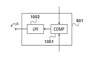
続いて、位相雑音推定部に変更を加えた第2の実施形態について、図10を用いて説明する。図10は、本発明の第2の実施形態の位相雑音推定部の構成を示すブロック図である。図10の位相雑音推定部における構成要素は、位相差分算出部901の違いを除いて、図3に示した第1の実施形態の位相雑音推定部の構成と同一である。図10の位相雑音推定部101aは、伝送する信号フレームの信号フォーマット中に(図7)、位相雑音補償用のパイロット信号を含む場合に好適である。[Second Embodiment]
Subsequently, a second embodiment in which the phase noise estimation unit is modified will be described with reference to FIG. 10. FIG. 10 is a block diagram showing a configuration of a phase noise estimation unit according to a second embodiment of the present invention. The components of the phase noise estimation unit of FIG. 10 are the same as the configuration of the phase noise estimation unit of the first embodiment shown in FIG. 3, except for the difference of the phase
図11は位相差分算出部901の構成を示すブロック図である。図10の位相差分算出部901は、前記パイロット信号に関する位相回転用乗算器201の出力を入力し、位相比較器1001でその位相差に関する情報を算出した後、ローパスフィルタ1002で高周波成分をカットして第一の位相雑音情報ejΔ=FPNを出力する。図10の位相雑音推定部101aに関するその他の動作は、前記図3の装置に関する動作と同様であるので説明を省略する。FIG. 11 is a block diagram showing the configuration of the phase
図12は、第2の実施形態の通信路状態推定部102の機能である通信路状態推定方法の手順を示すフローチャートである。図12は、受信信号をシンボルレートの2倍でサンプリング(ダブルサンプリング)した2倍サンプリング周波数領域等化に関するものであり、基本的な動作は図9の通信路状態推定方法の手順と同様である。
FIG. 12 is a flowchart showing the procedure of the channel state estimation method, which is a function of the channel
各送信アンテナから送信するトレーニング系列も同様であるが、これに対応する受信系列は長さが2Nであり、rT
(u)(0),rT
(u)(1),・・・,rT
(u)(2N-1)と記述する(uは1または2を表す)。2倍サンプリング用の通信路状態推定部102は、図12のフローチャート中の1101に示した演算方法に従って、長さ2Nの四つの系列h(u,v)(0),h(u,v)(1),・・・,h(u,v)(2N-1)を算出する(u,vは各々1または2を表す)。これは送信したトレーニング信号系列とそれに対応する受信信号の畳込み演算によって定まる長さ2Nの系列のうち、半数のN個の信号部分を0にマスクして得られる系列である。即ち、以上の処理が、送信アンテナ毎に送信される長さNのトレーニング信号の複素共役からなる信号系列p(v)*と、該トレーニング信号をLOS-MIMO伝送路への送信信号とし2倍でサンプリングした長さ2Nの受信信号rT
(u)とを、Nを法として畳込み演算して得られる長さ2Nの信号系列において、そのうち半数のN個の信号をゼロにマスクした長さ2Nの信号系列を算出する処理に相当する(図12の1101参照)。
The same applies to the training sequence transmitted from each transmitting antenna, but the corresponding receiving sequence has a length of 2N, and is r T (u) (0), r T (u) (1), ..., It is described as r T (u) (2N-1) (u represents 1 or 2). The channel
次に、通信路状態推定部102は、図12中の1102に示したように、これら四つの長さ2Nの系列h(u,v)(0),h(u,v)(1),・・・,h(u,v)(2N-1)を各々フーリエ変換して、長さ2Nの四つの系列H(u,v)(0),H(u,v)(1),・・・,H(u,v)(2N-1)を算出する。Next, as shown in 1102 in FIG. 12, the channel
最後に、通信路状態推定部102は、図12のフローチャート中の1103に示した処理によって、長さ2Nの四つの系列Q(u,v)(0),Q(u,v)(1),・・・,Q(u,v)(2N-1)を算出して出力する。尚、1103に示した処理は、LOS-MIMO伝送路の周波数応答をH(k),k=0,1,…,2N-1として平均自乗誤差が最小となる周波数領域等化のタップ係数を算出する手段に相当する。具体的には、前記長さ2Nの四つの系列Q(u,v)(0),Q(u,v)(1),・・・,Q(u,v)(2N-1)が周波数領域等化器105のタップ係数となる。Finally, the channel
以上説明したように、本発明は、信号フレームの信号フォーマットに、位相雑音補償用のパイロット信号が含まれる場合にも好適な形態に変形することが可能である。 As described above, the present invention can be transformed into a suitable form even when the signal format of the signal frame includes a pilot signal for phase noise compensation.
以上、本発明の各実施形態を説明したが、本発明は、上記した実施形態に限定されるものではなく、本発明の基本的技術的思想を逸脱しない範囲で、更なる変形・置換・調整を加えることができる。例えば、各図面に示したネットワーク構成、各要素の構成、メッセージの表現形態は、本発明の理解を助けるための一例であり、これらの図面に示した構成に限定されるものではない。 Although each embodiment of the present invention has been described above, the present invention is not limited to the above-described embodiment, and further modifications, substitutions, and adjustments are made without departing from the basic technical idea of the present invention. Can be added. For example, the network configuration, the configuration of each element, and the expression form of the message shown in each drawing are examples for assisting the understanding of the present invention, and are not limited to the configurations shown in these drawings.
例えば、実施形態では、送信アンテナ数と受信アンテナの数がそれぞれ2である例を挙げて説明したが、送信アンテナ数と受信アンテナの数は3本以上とすることができる。この場合、受信アンテナの数と同数の位相ロックループを用意し、その中の2つを選択して上記した実施形態の第1、第2のアンテナとすることで、第1、第2の位相雑音情報による干渉の除去を行うことができる。 For example, in the embodiment, the number of transmitting antennas and the number of receiving antennas are 2 respectively, but the number of transmitting antennas and the number of receiving antennas can be 3 or more. In this case, the same number of phase lock loops as the number of receiving antennas are prepared, and two of them are selected to be the first and second antennas of the above-described embodiment, so that the first and second phases are used. Interference due to noise information can be removed.
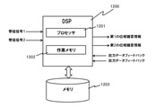
なお、各図に示したLOS-MIMO復調装置の各部(処理手段)は、LOS-MIMO復調装置を構成するコンピュータに、そのハードウェアを用いて、上記した各処理を実行させるコンピュータプログラムにより実現することもできる。例えば、図13に示すように、位相雑音推定部及び通信路状態推定部は、プロセッサ1201及び作業メモリ1202を備えるDSP(Digital Signal Prosessor)1200と、プロセッサ1201に上記した処理を行わせるプログラムを格納したメモリ1203とを含む構成にて実現できる。具体的には、プロセッサ1201が、メモリ1203から位相雑音推定部及び通信路状態推定部の処理に対応するプログラムを読み出して、受信信号1、2に基づいて、第1、第2の位相雑音情報を算出し、出力する構成を得ることができる。
Each part (processing means) of the LOS-MIMO demodulation device shown in each figure is realized by a computer program that causes a computer constituting the LOS-MIMO demodulation device to execute each of the above-mentioned processes by using the hardware thereof. You can also do it. For example, as shown in FIG. 13, the phase noise estimation unit and the communication path state estimation unit store a DSP (Digital Signal Processor) 1200 including a
最後に、本発明の好ましい形態を要約する。
[第1の形態]
(上記第1の視点によるLOS-MIMO復調装置参照)
[第2の形態]
第1の形態のLOS-MIMO復調装置において、
前記位相雑音推定部は、前記受信信号の組、又は、前記周波数領域等化処理後の信号を位相ロックループに入力して得られた信号の組から算出した位相差分を、前記第1の位相雑音情報として出力する位相差分算出部を備えるLOS-MIMO復調装置。
[第3の形態]
第1の形態のLOS-MIMO復調装置において、
前記第1の位相雑音情報は、第1の受信アンテナに付随する位相雑音と、第2の受信アンテナに付随する位相雑音を、それぞれφR
(1)、φR
(2)としたとき、次式を満たしているLOS-MIMO復調装置。
[式1]
![]()
第1から第3いずれか一の形態のLOS-MIMO復調装置において、
前記位相雑音推定部は、
受信信号からMIMO干渉成分を除去した後の信号を入力として、前記第2の位相雑音情報を出力する位相ロックループを備えるLOS-MIMO復調装置。
[第5の形態]
第1から第3いずれか一の形態のLOS-MIMO復調装置において、
前記第2の位相雑音情報は、2つの送信アンテナ及び2つの受信アンテナに付随する位相雑音を、それぞれφT
(1)、φT
(2)、φR
(1)、φR
(2)としたとき、次式を満たしているLOS-MIMO復調装置。
[式2]
![]()
![]()
第1から第5いずれか一の形態のLOS-MIMO復調装置において、
前記位相雑音推定部は、前記第二の位相雑音情報を算出する前記受信アンテナの数と同数の位相ロックループと、該位相ロックループの出力から第1の位相雑音情報を算出する位相差分算出部と、前記受信信号を重み付けして加算する乗算器、加算器、及び乗算係数生成部と、を有し、
前記複数の受信アンテナで受信した受信信号の各々の位相を、前記位相差分算出部の出力である第1の位相雑音情報によって補正し、該補正した受信信号の各々を前記重み付け加算処理した後、前記位相ロックループによって送信側の位相雑音に受信側の位相雑音の平均を加算した第二の位相雑音情報を算出するLOS-MIMO復調装置。
[第7の形態]
第1から第5いずれか一の形態のLOS-MIMO復調装置において、
前記位相雑音推定部は、前記受信信号から前記第1の位相雑音情報を算出する位相差分算出部と、前記第2の位相雑音情報を算出する前記受信アンテナの数と同数の位相ロックループと、前記受信信号を重み付けして加算する乗算器、加算器、及び乗算係数生成部と、を有し、
前記複数の受信アンテナで受信した受信信号の各々の位相を、前記位相差分算出部の出力である第1の位相雑音情報によって補正し、該補正した受信信号の各々を前記重み付け加算処理した後、前記位相ロックループによって前記第2の位相雑音情報を算出するLOS-MIMO復調装置。
[第8の形態]
第1から第7いずれか一の形態のLOS-MIMO復調装置において、
前記通信路状態推定部は、前記送信アンテナ毎に送信される長さNのトレーニング信号の複素共役からなる信号系列と、該トレーニング信号をLOS-MIMO伝送路への送信信号とし等倍でサンプリングした長さNの受信信号とを、畳込み演算して得られる長さNの信号系列において、そのうち半数のN/2個の信号をゼロにマスクした長さNの信号系列を算出する手段と、
該長さNの信号系列をフーリエ変換した信号を生成する手段と、
該フーリエ変換した信号をLOS-MIMO伝送路の周波数応答として、平均自乗誤差が最小となる等倍サンプリング周波数等化のタップ係数を算出する手段と、を備えるLOS-MIMO復調装置。
[第9の形態]
第1から第7いずれか一の形態のLOS-MIMO復調装置において、
前記通信路状態推定部は、前記送信アンテナ毎に送信される長さNのトレーニング信号の複素共役からなる信号系列と、該トレーニング信号をLOS-MIMO伝送路への送信信号とし2倍でサンプリングした長さ2Nの受信信号とを、Nを法として畳込み演算して得られる長さ2Nの信号系列において、そのうち半数のN個の信号をゼロにマスクした長さ2Nの信号系列を算出する手段と、
該長さ2Nの信号系列をフーリエ変換した信号を生成する手段と、
該フーリエ変換した信号をLOS-MIMO伝送路の周波数応答として、平均自乗誤差が最小となる2倍サンプリング周波数等化のタップ係数を算出する手段と、を備えるLOS-MIMO復調装置。
[第10の形態]
複数の固定的に配置された送信アンテナと受信アンテナを使い、アンテナ間の離隔距離によって調整された伝送遅延の差を利用して伝送路の多重化を行う見通し内多入力多出力(LOS-MIMO;Line of Sight Multiple Input Multiple Output)無線通信システムにおいて使用され、前記複数の受信アンテナにおいてそれぞれ受信された受信信号から送信データを推定するLOS-MIMO復調装置であって、
前記複数の受信アンテナで受信した受信信号の各々から干渉による歪を補償する周波数領域等化部と、前記周波数領域等化のタップ係数を算出する通信路状態推定部と、前記複数の受信アンテナで受信した受信信号の各々から、前記送信アンテナ及び受信アンテナにおいて生じた位相雑音に関連した第1の位相雑音情報と第2の位相雑音情報を算出する位相雑音推定部と、を有し、
前記複数の受信アンテナで受信した受信信号の各々の位相を、前記第1の位相雑音情報によって補正し、該補正した受信信号の各々を長さNの離散フーリエ変換によって周波数領域に変換して周波数領域等化処理を行った後、長さNの離散逆フーリエ変換によって時間領域に戻した周波数領域等化後の信号の位相を、前記第2の位相雑音情報によって補正するLOS-MIMO復調装置。
[第11の形態]
(上記第2の視点による通信装置参照)
[第12の形態]
(上記第3の視点によるLOS-MIMO伝送システム参照)
[第13の形態]
(上記第4の視点によるLOS-MIMO復調方法参照)
[第14の形態]
(上記第5の視点によるプログラム参照)
なお、上記第11~第14の形態は、第1の形態と同様に、第2~第10の形態に展開乃至変形することが可能である。
Finally, the preferred embodiments of the present invention are summarized.
[First form]
(See LOS-MIMO demodulator from the first viewpoint above)
[Second form]
In the LOS-MIMO demodulator of the first aspect,
The phase noise estimation unit uses the phase difference calculated from the set of received signals or the set of signals obtained by inputting the signal after the frequency region equalization process into the phase lock loop to obtain the first phase. A LOS-MIMO demodulator including a phase difference calculation unit that outputs noise information.
[Third form]
In the LOS-MIMO demodulator of the first aspect,
The first phase noise information is as follows when the phase noise associated with the first receiving antenna and the phase noise associated with the second receiving antenna are φ R (1) and φ R (2) , respectively. A LOS-MIMO demodulator that satisfies the equation.
[Equation 1]
![]()
In the LOS-MIMO demodulator of any one of the first to third forms,
The phase noise estimation unit is
A LOS-MIMO demodulator having a phase lock loop that outputs the second phase noise information by inputting a signal after removing a MIMO interference component from a received signal.
[Fifth form]
In the LOS-MIMO demodulator of any one of the first to third forms,
In the second phase noise information, the phase noises associated with the two transmitting antennas and the two receiving antennas are referred to as φ T (1) , φ T (2) , φ R (1) , and φ R (2) , respectively. Then, the LOS-MIMO demodulator that satisfies the following equation.
[Equation 2]
![]()
![]()
In the LOS-MIMO demodulator of any one of the first to fifth forms,
The phase noise estimation unit has the same number of phase lock loops as the number of receiving antennas for calculating the second phase noise information, and the phase difference calculation unit for calculating the first phase noise information from the output of the phase lock loop. And a multiplier, an adder, and a multiplication coefficient generator that weight and add the received signal.
Each phase of the received signal received by the plurality of receiving antennas is corrected by the first phase noise information which is the output of the phase difference calculation unit, and each of the corrected received signals is subjected to the weighted addition processing. A LOS-MIMO demodulator that calculates second phase noise information by adding the average of the phase noise on the receiving side to the phase noise on the transmitting side by the phase lock loop.
[7th form]
In the LOS-MIMO demodulator of any one of the first to fifth forms,
The phase noise estimation unit includes a phase difference calculation unit that calculates the first phase noise information from the received signal, a phase lock loop that has the same number as the number of the reception antennas that calculate the second phase noise information, and the phase lock loop. It has a multiplier, an adder, and a multiplication coefficient generator that weight and add the received signal.
Each phase of the received signal received by the plurality of receiving antennas is corrected by the first phase noise information which is the output of the phase difference calculation unit, and each of the corrected received signals is subjected to the weighted addition processing. A LOS-MIMO demodulator that calculates the second phase noise information by the phase lock loop.
[8th form]
In the LOS-MIMO demodulator of any one of the first to seventh forms,
The communication path state estimation unit samples a signal sequence consisting of a complex conjugate of a training signal of length N transmitted for each transmission antenna and the training signal as a transmission signal to the LOS-MIMO transmission path at the same magnification. As a means for calculating a signal sequence of length N obtained by convoluting the received signal of length N and masking half of the N / 2 signals to zero in the signal sequence of length N obtained. ,
A means for generating a signal obtained by Fourier transforming the signal sequence of length N,
A LOS-MIMO demodulator comprising a means for calculating a tap coefficient for equalizing the same-magnification sampling frequency that minimizes the mean self-squared error, using the Fourier-transformed signal as the frequency response of the LOS-MIMO transmission line.
[Ninth form]
In the LOS-MIMO demodulator of any one of the first to seventh forms,
The communication path state estimation unit doubles sampling a signal sequence consisting of a complex conjugate of a training signal of length N transmitted for each transmission antenna and the training signal as a transmission signal to the LOS-MIMO transmission path. In the signal sequence of
A means for generating a signal obtained by Fourier transforming the signal sequence having a length of 2N,
A LOS-MIMO demodulator comprising a means for calculating a tap coefficient for doubling sampling frequency equalization that minimizes an average self-squared error, using the Fourier-transformed signal as a frequency response of a LOS-MIMO transmission line.
[10th form]
In-line multi-input multi-output (LOS-MIMO) that uses multiple fixedly arranged transmitting and receiving antennas and multiplexes the transmission line using the difference in transmission delay adjusted by the separation distance between the antennas. A LOS-MIMO demodulator that is used in a radio communication system and estimates transmission data from received signals received by each of the plurality of receiving antennas.
The frequency domain equalization unit that compensates for distortion due to interference from each of the received signals received by the plurality of receiving antennas, the channel state estimation unit that calculates the tap coefficient of the frequency domain equalization, and the plurality of receiving antennas. It has a first phase noise information related to the phase noise generated in the transmission antenna and the reception antenna and a phase noise estimation unit for calculating a second phase noise information from each of the received reception signals.
The phase of each of the received signals received by the plurality of receiving antennas is corrected by the first phase noise information, and each of the corrected received signals is converted into a frequency domain by a discrete Fourier transform of length N to obtain a frequency. A LOS-MIMO demodulator that corrects the phase of a signal after frequency domain equalization, which is returned to the time domain by a discrete inverse Fourier transform of length N after performing region equalization processing, with the second phase noise information.
[11th form]
(Refer to the communication device from the second viewpoint above)
[Twelfth form]
(See LOS-MIMO transmission system from the third viewpoint above)
[13th form]
(Refer to the LOS-MIMO demodulation method from the fourth viewpoint above).
[14th form]
(Refer to the program from the fifth viewpoint above)
The eleventh to fourteenth forms can be expanded or transformed into the second to tenth forms in the same manner as the first form.
なお、上記の特許文献および非特許文献の各開示を、本書に引用をもって繰り込むものとする。本発明の全開示(請求の範囲を含む)の枠内において、さらにその基本的技術思想に基づいて、実施形態ないし実施例の変更・調整が可能である。また、本発明の開示の枠内において種々の開示要素(各請求項の各要素、各実施形態ないし実施例の各要素、各図面の各要素等を含む)の多様な組み合わせ、ないし選択が可能である。すなわち、本発明は、請求の範囲を含む全開示、技術的思想にしたがって当業者であればなし得るであろう各種変形、修正を含むことは勿論である。特に、本書に記載した数値範囲については、当該範囲内に含まれる任意の数値ないし小範囲が、別段の記載のない場合でも具体的に記載されているものと解釈されるべきである。 The disclosures of the above patented and non-patented documents shall be incorporated into this document by citation. Within the framework of the entire disclosure (including the scope of claims) of the present invention, it is possible to change or adjust the embodiments or examples based on the basic technical idea thereof. Further, within the framework of the disclosure of the present invention, various combinations or selections of various disclosure elements (including each element of each claim, each element of each embodiment or embodiment, each element of each drawing, etc.) are possible. Is. That is, it goes without saying that the present invention includes all disclosure including claims, various modifications and modifications that can be made by those skilled in the art in accordance with the technical idea. In particular, with respect to the numerical range described in this document, any numerical value or small range included in the range should be construed as being specifically described even if not otherwise described.
10、100 LOS-MIMO復調装置
11 第1の補正部
12、101、101a 位相雑音推定部
13 周波数領域等化部
14 第2の補正部
15 復号処理部
102 通信路状態推定部
103、108、201、501 位相回転用乗算器
104 高速フーリエ変換器
105 周波数領域等化器
106、702 加算器
107 逆高速フーリエ変換器
109 誤り訂正復号部
202 MIMO干渉除去用乗算器
203 乗算係数生成部
204 MIMO干渉除去用加算器
205 位相ロックループ
206 位相差分算出部
301 屋内装置(IDU)
302 屋外装置(ODU)
401 変調器
402 送信側位相雑音源
403 2x2 LOS-MIMO伝送路
404 フェージング通信路
405 MIMO干渉
406 受信側位相雑音源
407 熱雑音源
701 乗算器
703、1001 位相比較器
704、1002 ローパスフィルタ
801、802、803、1101、1102、1103 通信路状態推定方法における演算手順
901 位相差分算出部
1200 DSP
1201 プロセッサ
1202 作業メモリ
1203 メモリ10, 100 LOS-
302 Outdoor equipment (ODU)
1201
Claims (15)
前記複数の受信アンテナで受信した受信信号の各々から、送信アンテナ及び前記受信アンテナにおいて生じた位相雑音に関連した第1の位相雑音情報と第2の位相雑音情報を算出する位相雑音推定部と、
前記複数の受信アンテナで受信した受信信号の各々の位相を、前記第1の位相雑音情報によって補正する第1の補正部と、
前記補正後の受信信号に対し、前記複数の受信アンテナで受信した受信信号の各々から干渉による歪を補償する周波数領域等化処理を行う周波数領域等化部と、
離散逆フーリエ変換によって前記周波数領域等化処理後の信号を時間領域に戻した信号の位相を、前記第2の位相雑音情報によって補正する第2の補正部と、
前記補正後のデータの復号処理を行う復号処理部と、
を備えたLOS-MIMO復調装置。 Multiple receiving antennas that receive data transmitted by line-of-sight multiple inputs and multiple outputs (LOS-MIMO; Line of Gigabit Input Multiple Output).
A phase noise estimation unit that calculates first phase noise information and second phase noise information related to the phase noise generated in the transmitting antenna and the receiving antenna from each of the received signals received by the plurality of receiving antennas.
A first correction unit that corrects the phase of each of the received signals received by the plurality of receiving antennas by the first phase noise information, and
A frequency domain equalization unit that performs frequency domain equalization processing to compensate for distortion due to interference from each of the received signals received by the plurality of receiving antennas with respect to the corrected received signal.
A second correction unit that corrects the phase of the signal obtained by returning the signal after the frequency domain equalization process to the time domain by the discrete inverse Fourier transform with the second phase noise information.
A decoding processing unit that performs decoding processing of the corrected data, and
LOS-MIMO demodulator equipped with.
受信信号からMIMO干渉成分を除去した後の信号を入力として、前記第2の位相雑音情報を出力する位相ロックループを備える請求項1から3いずれか一のLOS-MIMO復調装置。 The phase noise estimation unit is
The LOS-MIMO demodulator according to any one of claims 1 to 3, further comprising a phase lock loop that outputs the second phase noise information by inputting a signal after removing the MIMO interference component from the received signal.
前記複数の受信アンテナで受信した受信信号の各々の位相を、前記位相差分算出部の出力である第1の位相雑音情報によって補正し、該補正した受信信号の各々を前記重み付け加算処理した後、前記位相ロックループによって送信側の位相雑音に受信側の位相雑音の平均を加算した第2の位相雑音情報を算出すること、を特徴とする請求項1から5いずれか一のLOS-MIMO復調装置。 The phase noise estimation unit has the same number of phase lock loops as the number of receiving antennas for calculating the second phase noise information, and the phase difference calculation unit for calculating the first phase noise information from the output of the phase lock loop. And a multiplier, an adder, and a multiplication coefficient generator that weight and add the received signal.
Each phase of the received signal received by the plurality of receiving antennas is corrected by the first phase noise information which is the output of the phase difference calculation unit, and each of the corrected received signals is subjected to the weighted addition processing. The LOS-MIMO demodulator according to any one of claims 1 to 5, wherein the second phase noise information is calculated by adding the average of the phase noises on the receiving side to the phase noises on the transmitting side by the phase lock loop. ..
前記複数の受信アンテナで受信した受信信号の各々の位相を、前記位相差分算出部の出力である第1の位相雑音情報によって補正し、該補正した受信信号の各々を前記重み付け加算処理した後、前記位相ロックループによって前記第2の位相雑音情報を算出すること、を特徴とする請求項1から5いずれか一のLOS-MIMO復調装置。 The phase noise estimation unit includes a phase difference calculation unit that calculates the first phase noise information from the received signal, a phase lock loop that has the same number as the number of the reception antennas that calculate the second phase noise information, and the phase lock loop. It has a multiplier, an adder, and a multiplication coefficient generator that weight and add the received signal.
Each phase of the received signal received by the plurality of receiving antennas is corrected by the first phase noise information which is the output of the phase difference calculation unit, and each of the corrected received signals is subjected to the weighted addition processing. The LOS-MIMO demodulator according to any one of claims 1 to 5, wherein the second phase noise information is calculated by the phase lock loop.
該長さNの信号系列をフーリエ変換した信号を生成する手段と、
該フーリエ変換した信号をLOS-MIMO伝送路の周波数応答として、平均自乗誤差が最小となる等倍サンプリング周波数等化のタップ係数を算出する手段と、を備える請求項1から7いずれか一のLOS-MIMO復調装置。 As a communication path state estimation unit, a signal sequence consisting of a complex conjugate of a training signal of length N transmitted for each transmission antenna and a length of the training signal sampled at the same magnification as a transmission signal to the LOS-MIMO transmission path. In the signal sequence of length N obtained by convoluting the received signal of S N, a means for calculating a signal sequence of length N obtained by masking half of N / 2 signals to zero.
A means for generating a signal obtained by Fourier transforming the signal sequence of length N,
The LOS according to any one of claims 1 to 7, wherein the Fourier transformed signal is used as a frequency response of a LOS-MIMO transmission line, and a means for calculating a tap coefficient for equalizing the same magnification sampling frequency that minimizes the mean self-squared error is provided. -MIMO demodulator.
該長さ2Nの信号系列をフーリエ変換した信号を生成する手段と、
該フーリエ変換した信号をLOS-MIMO伝送路の周波数応答として、平均自乗誤差が最小となる2倍サンプリング周波数等化のタップ係数を算出する手段と、を備える請求項1から7いずれか一のLOS-MIMO復調装置。 As a communication path state estimation unit, a signal sequence consisting of a complex conjugate of a training signal of length N transmitted for each transmission antenna and the training signal as a transmission signal to the LOS-MIMO transmission path were sampled twice. A means for calculating a signal sequence having a length of 2N in which half of the N signals are masked to zero in a signal sequence having a length of 2N obtained by convoluting a received signal having a length of 2N using N as a method. When,
A means for generating a signal obtained by Fourier transforming the signal sequence having a length of 2N,
The LOS according to any one of claims 1 to 7, wherein the Fourier transformed signal is used as the frequency response of the LOS-MIMO transmission line, and a means for calculating the tap coefficient of double sampling frequency equalization that minimizes the mean self-squared error is provided. -MIMO demodulator.
前記複数の受信アンテナで受信した受信信号の各々から干渉による歪を補償する周波数領域等化部と、前記周波数領域等化のタップ係数を算出する通信路状態推定部と、前記複数の受信アンテナで受信した受信信号の各々から、前記送信アンテナ及び受信アンテナにおいて生じた位相雑音に関連した第1の位相雑音情報と第2の位相雑音情報を算出する位相雑音推定部と、を有し、
前記複数の受信アンテナで受信した受信信号の各々の位相を、前記第1の位相雑音情報によって補正し、該補正した受信信号の各々を長さNの離散フーリエ変換によって周波数領域に変換して周波数領域等化処理を行った後、長さNの離散逆フーリエ変換によって時間領域に戻した周波数領域等化後の信号の位相を、前記第2の位相雑音情報によって補正すること、を特徴としたLOS-MIMO復調装置。 In-line multi-input multi-output (LOS-MIMO) that uses multiple fixedly arranged transmitting and receiving antennas and multiplexes the transmission line using the difference in transmission delay adjusted by the separation distance between the antennas. Line of Simple Input Multiple Output) A LOS-MIMO demodulator that is used in wireless communication systems and estimates transmission data from received signals received by multiple receiving antennas.
The frequency domain equalization unit that compensates for distortion due to interference from each of the received signals received by the plurality of receiving antennas, the channel state estimation unit that calculates the tap coefficient of the frequency domain equalization, and the plurality of receiving antennas. It has a first phase noise information related to the phase noise generated in the transmission antenna and the reception antenna and a phase noise estimation unit for calculating a second phase noise information from each of the received reception signals.
The phase of each of the received signals received by the plurality of receiving antennas is corrected by the first phase noise information, and each of the corrected received signals is converted into a frequency domain by a discrete Fourier transform of length N to obtain a frequency. The feature is that the phase of the signal after the frequency domain equalization, which is returned to the time domain by the discrete inverse Fourier transform of length N after the domain equalization process, is corrected by the second phase noise information. LOS-MIMO demodulator.
複数の固定的に配置された送信アンテナと受信アンテナを使い、アンテナ間の離隔距離によって調整された伝送遅延の差を利用して伝送路の多重化を行うLOS-MIMO伝送システム。 The LOS-MIMO demodulator according to any one of claims 1 to 10 is included.
A LOS-MIMO transmission system that uses multiple fixedly arranged transmitting and receiving antennas and multiplexes the transmission line using the difference in transmission delay adjusted by the separation distance between the antennas.
送信側が、複数の送信アンテナから送信される信号の各々に対し、前記第2の位相雑音情報を使用して位相回転処理を行った後、送信することを特徴とした請求項12のLOS-MIMO伝送システム。 It has a function of feeding back the second phase noise information calculated by the LOS-MIMO demodulator to the transmitting side.
The LOS-MIMO according to claim 12, wherein the transmitting side performs phase rotation processing on each of the signals transmitted from the plurality of transmitting antennas using the second phase noise information, and then transmits the signals. Transmission system.
前記複数の受信アンテナで受信した受信信号の各々の位相を、前記第1の位相雑音情報によって補正するステップと、
前記補正後の受信信号に対し、前記複数の受信アンテナで受信した受信信号の各々から干渉による歪を補償する周波数領域等化処理を行うステップと、
離散逆フーリエ変換によって前記周波数領域等化処理後の信号を時間領域に戻した信号の位相を、前記第2の位相雑音情報によって補正するステップと、
を含むLOS-MIMO復調方法。 Generated from each of the received signals received by the plurality of receiving antennas of the LOS-MIMO demodulator constituting the line-of-sight multi-input multi-output (LOS-MIMO; Line of Phase Input Multiple Output) at the transmitting antenna and the receiving antenna. The step of calculating the first phase noise information and the second phase noise information related to the phase noise, and
A step of correcting each phase of the received signal received by the plurality of receiving antennas by the first phase noise information, and a step of correcting each phase.
A step of performing frequency domain equalization processing on the corrected received signal to compensate for distortion due to interference from each of the received signals received by the plurality of receiving antennas.
A step of correcting the phase of the signal obtained by returning the signal after the frequency domain equalization process to the time domain by the discrete inverse Fourier transform by the second phase noise information.
LOS-MIMO demodulation method including.
複数の受信アンテナで受信した受信信号の各々から、送信アンテナ及び前記受信アンテナにおいて生じた位相雑音に関連した第1の位相雑音情報と第2の位相雑音情報を算出する処理と、
前記複数の受信アンテナで受信した受信信号の各々の位相を、前記第1の位相雑音情報によって補正する処理と、
前記補正後の受信信号に対し、前記複数の受信アンテナで受信した受信信号の各々から干渉による歪を補償する周波数領域等化処理を行う処理と、
離散逆フーリエ変換によって前記周波数領域等化処理後の信号を時間領域に戻した信号の位相を、前記第2の位相雑音情報によって補正する処理と、
を実行させるプログラム。 To the computer that configures the LOS-MIMO demodulator that configures line-of-sight multi-input and multi-output (LOS-MIMO; Line of Gigabit Input Multiple Output).
Processing to calculate the first phase noise information and the second phase noise information related to the phase noise generated in the transmitting antenna and the receiving antenna from each of the received signals received by the plurality of receiving antennas.
The process of correcting the phase of each of the received signals received by the plurality of receiving antennas by the first phase noise information, and
A process of performing frequency domain equalization processing on the corrected received signal to compensate for distortion due to interference from each of the received signals received by the plurality of receiving antennas.
The process of correcting the phase of the signal obtained by returning the signal after the frequency domain equalization process to the time domain by the discrete inverse Fourier transform by the second phase noise information.
A program to execute.
Applications Claiming Priority (3)
| Application Number | Priority Date | Filing Date | Title |
|---|---|---|---|
| JP2016083552 | 2016-04-19 | ||
| JP2016083552 | 2016-04-19 | ||
| PCT/JP2017/015562 WO2017183631A1 (en) | 2016-04-19 | 2017-04-18 | Los-mimo demodulation device, communication device, los-mimo transmission system, los-mimo demodulation method and program |
Publications (2)
| Publication Number | Publication Date |
|---|---|
| JPWO2017183631A1 JPWO2017183631A1 (en) | 2019-02-21 |
| JP6996496B2 true JP6996496B2 (en) | 2022-01-17 |
Family
ID=60116109
Family Applications (1)
| Application Number | Title | Priority Date | Filing Date |
|---|---|---|---|
| JP2018513185A Active JP6996496B2 (en) | 2016-04-19 | 2017-04-18 | LOS-MIMO demodulation device, communication device, LOS-MIMO transmission system, LOS-MIMO demodulation method and program |
Country Status (3)
| Country | Link |
|---|---|
| US (1) | US10523283B2 (en) |
| JP (1) | JP6996496B2 (en) |
| WO (1) | WO2017183631A1 (en) |
Families Citing this family (8)
| Publication number | Priority date | Publication date | Assignee | Title |
|---|---|---|---|---|
| US10425182B2 (en) * | 2017-09-29 | 2019-09-24 | Futurewei Technologies, Inc. | Inter-band distortion and interference mitigation within communication systems |
| JP7044972B2 (en) * | 2018-07-04 | 2022-03-31 | 日本電信電話株式会社 | Wireless communication device and wireless communication method |
| WO2020217941A1 (en) * | 2019-04-25 | 2020-10-29 | 日本電気株式会社 | Modulation device and demodulation device |
| US10708107B1 (en) * | 2019-09-10 | 2020-07-07 | Huawei Technologies Co., Ltd. | Method and decoder for suppressing phase noise in an orthogonal frequency division multiplexing signal |
| US20250202734A1 (en) * | 2022-03-28 | 2025-06-19 | Telefonaktiebolaget Lm Ericsson (Publ) | Los-mimo microwave radio link channel estimation for rank deficient channels |
| US12088370B2 (en) * | 2022-09-27 | 2024-09-10 | Qualcomm Incorporated | Parallel shift estimation for LOS MIMO communication |
| CN116915554B (en) * | 2023-08-03 | 2026-04-28 | 西安交通大学 | A method and system for estimating and compensating phase noise in millimeter-wave LOS-MIMO OFDM |
| CN119484208B (en) * | 2024-09-27 | 2026-03-20 | 北京理工大学 | A near-field communication and ranging integration method based on LOS MIMO |
Citations (2)
| Publication number | Priority date | Publication date | Assignee | Title |
|---|---|---|---|---|
| JP2005252602A (en) | 2004-03-03 | 2005-09-15 | Nippon Telegr & Teleph Corp <Ntt> | Phase noise correction apparatus and spatial multiplexing signal receiving apparatus |
| JP2006197132A (en) | 2005-01-12 | 2006-07-27 | Sony Corp | Wireless communication apparatus and wireless communication method |
Family Cites Families (9)
| Publication number | Priority date | Publication date | Assignee | Title |
|---|---|---|---|---|
| RU2439826C2 (en) | 2007-02-16 | 2012-01-10 | Нек Корпорейшн | Radio transmission system and method for compensating for cross-talk |
| EP2219310A4 (en) | 2007-11-30 | 2014-02-19 | Nec Corp | Wireless communication system, receiver, transmitter, warless communication method, receiving method, and transmitting method |
| WO2009154278A1 (en) | 2008-06-20 | 2009-12-23 | 日本電信電話株式会社 | Receiver device, transmitting system and reception method |
| JP5246771B2 (en) | 2008-11-11 | 2013-07-24 | 国立大学法人東京工業大学 | Phase noise compensation receiver |
| JP5452174B2 (en) | 2009-10-30 | 2014-03-26 | 三菱電機株式会社 | MIMO receiver |
| US8767575B2 (en) * | 2010-08-06 | 2014-07-01 | Futurewei Technologies, Inc. | Method and apparatus for broadband carrier frequency and phase recovery in coherent optical system |
| CN104272692B (en) | 2012-04-24 | 2017-09-26 | 日本电气株式会社 | Carrier regeneration device and carrier regeneration method |
| US9077407B2 (en) * | 2012-05-15 | 2015-07-07 | Broadcom Corporation | Geometrical closed loop line of sight (LOS) multiple-input-multiple-output (MIMO) |
| US9391817B2 (en) * | 2014-03-24 | 2016-07-12 | Tensorcom, Inc. | Method and apparatus of an architecture to switch equalization based on signal delay spread |
-
2017
- 2017-04-18 JP JP2018513185A patent/JP6996496B2/en active Active
- 2017-04-18 WO PCT/JP2017/015562 patent/WO2017183631A1/en not_active Ceased
- 2017-04-18 US US16/081,076 patent/US10523283B2/en active Active
Patent Citations (2)
| Publication number | Priority date | Publication date | Assignee | Title |
|---|---|---|---|---|
| JP2005252602A (en) | 2004-03-03 | 2005-09-15 | Nippon Telegr & Teleph Corp <Ntt> | Phase noise correction apparatus and spatial multiplexing signal receiving apparatus |
| JP2006197132A (en) | 2005-01-12 | 2006-07-27 | Sony Corp | Wireless communication apparatus and wireless communication method |
Non-Patent Citations (1)
| Title |
|---|
| Rui Lv, Meng Cai, Zihuan Chen, Jun Ma, Xiaodong Li,Phase noise suppression for realistic LOS-MIMO microwave backhaul systems,2013 Asia-Pacific Microwave Conference Proceedings(APMC),2013年11月08日,p.794-796 |
Also Published As
| Publication number | Publication date |
|---|---|
| JPWO2017183631A1 (en) | 2019-02-21 |
| WO2017183631A1 (en) | 2017-10-26 |
| US10523283B2 (en) | 2019-12-31 |
| US20190020384A1 (en) | 2019-01-17 |
Similar Documents
| Publication | Publication Date | Title |
|---|---|---|
| JP6996496B2 (en) | LOS-MIMO demodulation device, communication device, LOS-MIMO transmission system, LOS-MIMO demodulation method and program | |
| CN101647251B (en) | Frequency offset correction | |
| US10237095B2 (en) | Linear equalization for use in low latency high speed communication systems | |
| JP7201075B2 (en) | demodulator | |
| KR101062049B1 (en) | Receiving device and receiving method | |
| JP2008017143A (en) | Radio receiving apparatus and method | |
| JP6583292B2 (en) | MIMO demodulation apparatus and method, and line-of-sight MIMO wireless communication system | |
| TWI381669B (en) | Receiver in mimo ofdm communications system and method for estimating phase error | |
| JP6019298B2 (en) | Wireless communication system, wireless transmission device, and wireless communication method | |
| JP7180514B2 (en) | Wireless communication system, wireless communication method, transmitting station device and receiving station device | |
| JP2020141173A (en) | Wireless communication system, wireless communication method, transmitting station equipment and receiving station equipment | |
| JP2007110664A (en) | MIMO precoding method | |
| JP7845063B2 (en) | Wireless transmitter | |
| US10103906B2 (en) | Method and apparatus for attenuating interference or cancelling interference in filter bank multicarrier system | |
| JPWO2008156133A1 (en) | Compensation method, program, recording medium, and receiver for OFDM signal having CFO and DCO | |
| JP7298695B2 (en) | Wireless communication system, wireless communication method, transmitting station device and receiving station device | |
| WO2020085253A1 (en) | Wireless communication system, wireless communication method, transmitting station device, and receiving station device | |
| WO2017167386A1 (en) | A transmitter for transmitting and a receiver for receiving a plurality of multicarrier modulation signals | |
| JP4925418B2 (en) | Transmitting apparatus and communication system | |
| EP2244432A1 (en) | Compensating carrier frequency offsets in OFDM systems | |
| JP7302734B2 (en) | Wireless communication system, wireless communication method and transmitter | |
| JP6209087B2 (en) | Receiving apparatus and program | |
| JP7107271B2 (en) | Wireless communication system, wireless communication method, transmitting station device and receiving station device | |
| WO2022102063A1 (en) | Wireless communication system, wireless communication method, and receiving device | |
| JP2013150271A (en) | Receiver and receiving method |
Legal Events
| Date | Code | Title | Description |
|---|---|---|---|
| A621 | Written request for application examination |
Free format text: JAPANESE INTERMEDIATE CODE: A621 Effective date: 20200304 |
|
| A131 | Notification of reasons for refusal |
Free format text: JAPANESE INTERMEDIATE CODE: A131 Effective date: 20210525 |
|
| A521 | Request for written amendment filed |
Free format text: JAPANESE INTERMEDIATE CODE: A523 Effective date: 20210621 |
|
| TRDD | Decision of grant or rejection written | ||
| A01 | Written decision to grant a patent or to grant a registration (utility model) |
Free format text: JAPANESE INTERMEDIATE CODE: A01 Effective date: 20211116 |
|
| A61 | First payment of annual fees (during grant procedure) |
Free format text: JAPANESE INTERMEDIATE CODE: A61 Effective date: 20211129 |
|
| R150 | Certificate of patent or registration of utility model |
Ref document number: 6996496 Country of ref document: JP Free format text: JAPANESE INTERMEDIATE CODE: R150 |