JP6996486B2 - Winding inductor component - Google Patents
Winding inductor component Download PDFInfo
- Publication number
- JP6996486B2 JP6996486B2 JP2018235718A JP2018235718A JP6996486B2 JP 6996486 B2 JP6996486 B2 JP 6996486B2 JP 2018235718 A JP2018235718 A JP 2018235718A JP 2018235718 A JP2018235718 A JP 2018235718A JP 6996486 B2 JP6996486 B2 JP 6996486B2
- Authority
- JP
- Japan
- Prior art keywords
- electrode
- layer
- plating layer
- inductor component
- shaft portion
- Prior art date
- Legal status (The legal status is an assumption and is not a legal conclusion. Google has not performed a legal analysis and makes no representation as to the accuracy of the status listed.)
- Active
Links
Images
Classifications
-
- H—ELECTRICITY
- H01—ELECTRIC ELEMENTS
- H01F—MAGNETS; INDUCTANCES; TRANSFORMERS; SELECTION OF MATERIALS FOR THEIR MAGNETIC PROPERTIES
- H01F27/00—Details of transformers or inductances, in general
- H01F27/28—Coils; Windings; Conductive connections
- H01F27/29—Terminals; Tapping arrangements for signal inductances
- H01F27/292—Surface mounted devices
-
- H—ELECTRICITY
- H01—ELECTRIC ELEMENTS
- H01F—MAGNETS; INDUCTANCES; TRANSFORMERS; SELECTION OF MATERIALS FOR THEIR MAGNETIC PROPERTIES
- H01F17/00—Fixed inductances of the signal type
- H01F17/04—Fixed inductances of the signal type with magnetic core
- H01F17/045—Fixed inductances of the signal type with magnetic core with core of cylindric geometry and coil wound along its longitudinal axis, i.e. rod or drum core
-
- H—ELECTRICITY
- H01—ELECTRIC ELEMENTS
- H01F—MAGNETS; INDUCTANCES; TRANSFORMERS; SELECTION OF MATERIALS FOR THEIR MAGNETIC PROPERTIES
- H01F27/00—Details of transformers or inductances, in general
- H01F27/24—Magnetic cores
-
- H—ELECTRICITY
- H01—ELECTRIC ELEMENTS
- H01F—MAGNETS; INDUCTANCES; TRANSFORMERS; SELECTION OF MATERIALS FOR THEIR MAGNETIC PROPERTIES
- H01F27/00—Details of transformers or inductances, in general
- H01F27/28—Coils; Windings; Conductive connections
- H01F27/2823—Wires
- H01F27/2828—Construction of conductive connections, of leads
-
- H—ELECTRICITY
- H01—ELECTRIC ELEMENTS
- H01F—MAGNETS; INDUCTANCES; TRANSFORMERS; SELECTION OF MATERIALS FOR THEIR MAGNETIC PROPERTIES
- H01F27/00—Details of transformers or inductances, in general
- H01F27/34—Special means for preventing or reducing unwanted electric or magnetic effects, e.g. no-load losses, reactive currents, harmonics, oscillations, leakage fields
- H01F27/36—Electric or magnetic shields or screens
Landscapes
- Engineering & Computer Science (AREA)
- Power Engineering (AREA)
- Microelectronics & Electronic Packaging (AREA)
- Coils Or Transformers For Communication (AREA)
Description
本開示は、コアに巻回されたワイヤを有する巻線型インダクタ部品に関する。 The present disclosure relates to a wound inductor component having a wire wound around a core.
従来、電子機器には種々のインダクタ部品が搭載されている。巻線型インダクタ部品は、コアと、コアに巻回されたワイヤとを有している。ワイヤの端部は、コアに設けられた端子電極と接続されている。通常、ワイヤの端部は、製造コストの観点から、例えば特許文献1に記載されているように、ヒータチップを用いて端子電極と熱圧着される。この熱圧着時に端子電極が溶解することを防止するため、端子電極は、ニッケル(Ni)又はニッケルを含む合金からなるニッケル電極層を含むめっき層を備える。 Conventionally, various inductor components are mounted on electronic devices. The winding inductor component has a core and a wire wound around the core. The end of the wire is connected to a terminal electrode provided on the core. Usually, the end of the wire is thermocompression bonded to the terminal electrode using a heater tip, for example, as described in Patent Document 1, from the viewpoint of manufacturing cost. In order to prevent the terminal electrode from melting during this thermocompression bonding, the terminal electrode includes a plating layer including a nickel electrode layer made of nickel (Ni) or an alloy containing nickel.
しかしながら、ニッケルは磁性体であるため、ニッケルを含む端子電極を備えた巻線型インダクタ部品を強磁場の環境で使用した場合、ニッケルが磁場に反応して周囲の磁場が乱れるという問題があった。例えば、当該巻線型インダクタ部品をMRI(magnetic resonance imaging(核磁気共鳴画像法))で使用した場合、端子電極のニッケルが磁場に反応して周囲の磁場が乱れることにより、撮影画像が乱れる虞がある。このように、巻線型インダクタ部品の端子電極に含まれるニッケルが周囲の磁場に影響を与えることが問題となっていた。 However, since nickel is a magnetic material, when a wound-wound inductor component provided with a terminal electrode containing nickel is used in an environment of a strong magnetic field, there is a problem that nickel reacts with the magnetic field and the surrounding magnetic field is disturbed. For example, when the winding type inductor component is used in MRI (magnetic resonance imaging), the nickel of the terminal electrode reacts with the magnetic field and the surrounding magnetic field is disturbed, so that the captured image may be disturbed. be. As described above, there has been a problem that nickel contained in the terminal electrode of the wire-wound inductor component affects the surrounding magnetic field.
本開示の目的は、周囲の磁場への影響を低減できる巻線型インダクタ部品を提供することにある。 An object of the present disclosure is to provide a wire wound inductor component capable of reducing the influence on an ambient magnetic field.
本開示の一態様である巻線型インダクタ部品は、柱状の軸部及び前記軸部の両端に設けられた一対の支持部を有するコアと、一対の前記支持部の各々に設けられた非磁性体の端子電極と、前記軸部に巻回され両端部がそれぞれ一対の前記支持部の前記端子電極に接続されたワイヤと、を備えた。 The wire-wound inductor component according to one aspect of the present disclosure includes a core having a columnar shaft portion and a pair of support portions provided at both ends of the shaft portion, and a non-magnetic material provided on each of the pair of the support portions. The terminal electrode is provided with a wire wound around the shaft portion and having both ends connected to the terminal electrode of the pair of the support portions.
上記態様によれば、端子電極は非磁性体であるため、端子電極が周囲の磁場に反応することが抑制される。従って、周囲の磁場への影響を低減できる。 According to the above aspect, since the terminal electrode is a non-magnetic material, the terminal electrode is suppressed from reacting with the surrounding magnetic field. Therefore, the influence on the surrounding magnetic field can be reduced.
以下、巻線型インダクタ部品の一実施形態について説明する。なお、添付図面は、理解を容易にするために構成要素を拡大して示している場合がある。構成要素の寸法比率は実際のものと、又は別の図中のものと異なる場合がある。また、断面図ではハッチングを付しているが、理解を容易にするために、一部の構成要素のハッチングを省略している場合がある。 Hereinafter, an embodiment of the wire wound inductor component will be described. It should be noted that the attached drawings may show enlarged components for ease of understanding. The dimensional ratio of the components may differ from the actual one or the one in another figure. In addition, although hatching is attached in the cross-sectional view, hatching of some components may be omitted for ease of understanding.
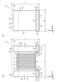
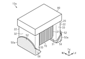
図1(a)、図1(b)及び図2に示す巻線型インダクタ部品10(以下、インダクタ部品10と記載する)は、例えば回路基板等に実装される表面実装型の巻線型インダクタ部品である。このインダクタ部品10は、例えば、MRI(magnetic resonance imaging(核磁気共鳴画像法))等の検査装置に備えられる回路(高周波回路等)に使用される他、様々なデバイスで使用され得る。
The wire wound inductor component 10 (hereinafter referred to as an inductor component 10) shown in FIGS. 1 (a), 1 (b) and 2 is a surface mount type wire wound inductor component mounted on a circuit board or the like, for example. be. The
インダクタ部品10は、柱状の軸部21及び軸部21の両端に設けられた一対の支持部22を有するコア20と、一対の支持部22の各々に設けられた非磁性体の端子電極50と、軸部21に巻回され両端部がそれぞれ一対の支持部22の端子電極50に接続されたワイヤ70とを有する。
The
軸部21は長さ方向Ldに平行に延びる四角柱状に形成されている。一対の支持部22は、軸部21の両端から長さ方向Ldと直交して延びる長方形状の主面を有する鍔状に形成されている。支持部22は軸部21の延びる第1の方向が実装対象(例えば回路基板)と平行となるように支持する。一対の支持部22は、軸部21と一体に形成されている。なお、軸部21及び一対の支持部22は、バレル加工や面取り加工などによって、角部及び稜線部が曲面又は平面となっていることが好ましい。
The
図1(a)及び図1(b)に示すように、各支持部22は、長さ方向Ldにおいて軸部21側を向いた内面31と、内面31と反対側の外側を向いた端面32と、幅方向Wdの両側の一対の側面33,34と、高さ方向Tdの両側の天面35及び底面36とを有している。一方の支持部22の内面31は、他方の支持部22の内面31と対向している。なお、底面36は、インダクタ部品10を回路基板に実装する際に回路基板と対向する面、より具体的には、両側の支持部ともに端子電極が形成されている側の面である。天面35は、底面36と反対側の面である。側面33,34は、内面31、端面32、天面35及び底面36ではない面である。
As shown in FIGS. 1A and 1B, each
上記のように、本明細書においては、軸部21の延びる方向を「長さ方向Ld」と定義する。また、「高さ方向Td」は、「長さ方向Ld」に直交する方向のうち、底面36に直交する方向と定義する。更に、「幅方向Wd」は、「長さ方向Ld」及び「高さ方向Td」に直交する方向と定義する。なお、「高さ方向Td」は、インダクタ部品10が実装される回路基板からの高さを示し、「長さ方向Ld」及び「幅方向Wd」は、当該回路基板においてインダクタ部品10が占める実装領域を示す。
As described above, in the present specification, the extending direction of the
本実施形態のインダクタ部品10は、例えば、長さ方向Ldの大きさ(長さ寸法L1)が1.6mm、高さ方向Tdの大きさ(高さ寸法T1)及び幅方向Wdの大きさ(幅寸法W1)が0.8mmである。なお、インダクタ部品10の長さ寸法L1、高さ寸法T1及び幅寸法W1はこれに限らない。例えば、インダクタ部品10は、長さ寸法L1が0.2mm以上、2.5mm以下であってもよいし、高さ寸法T1及び幅寸法W1が0.1mm以上、2.0mm以下であってもよい。また例えば、インダクタ部品10は、高さ寸法T1と幅寸法W1とが異なっていてもよい。
The
図3に示すように、支持部22は、底面36と内面31との境界をなす稜線部41と、底面36と端面32との境界をなす稜線部42と、天面35と内面31との境界をなす稜線部43と、天面35と端面32との境界をなす稜線部44とを有している。稜線部41~44の表面は、コア20の外側に向かって凸となる曲面状であり、概略円柱面(凸円柱面)である。なお、図3では示されないが、支持部22は、側面33,34と内面31、端面32、天面35、底面36とのそれぞれの境界をなす稜線部も有し、当該稜線部も凸円柱面である。各稜線部の曲率半径は、本実施形態では等しいが、異ならせてもよい。
As shown in FIG. 3, the
コア20の材料としては、磁性材料(例えば、ニッケル(Ni)-亜鉛(Zn)系フェライト、マンガン(Mn)-亜鉛系フェライト、鉄(Fe)系金属磁性粉含有樹脂)、非磁性材料(酸化アルミニウム、ガラス)などを用いることができる。コア20は、セラミックス(焼結体)であってもよいし、成形体であってもよい。因みに、本実施形態のコア20は、酸化アルミニウムを材料としたアルミナセラミックスよりなる。
The material of the
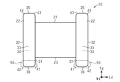
図1(a)、図1(b)及び図2に示すように、端子電極50は、各支持部22の底面36側に形成されている。端子電極50は、支持部22の底面36に形成された底面部電極51と、支持部22の端面32に形成された端面部電極52と、支持部22の内面31に形成された内面部電極53と、支持部22の側面33,34に形成された側面部電極54とを有する。
As shown in FIGS. 1 (a), 1 (b) and 2, the
底面部電極51は、支持部22の底面36の全体に亘って形成されており、底面36を覆っている。端面部電極52は、支持部22の端面32の下部を覆うように形成されている。内面部電極53は、支持部22の内面31の下部を覆うように形成されている。また、側面部電極54は、側面33,34の下部を覆うように形成されている。
The
底面部電極51と端面部電極52とは、底面36と端面32との間の稜線部42上の部分を介して連続するように形成されている。底面部電極51と内面部電極53とは、底面36と内面31との間の稜線部41上の部分を介して連続するように形成されている。底面部電極51と側面部電極54とは、底面36と側面33,34との間の稜線部上の部分を介して連続するように形成されている。また、端面部電極52と側面部電極54とは、端面32と側面33,34との間の稜線部上の部分を介して連続するように形成されている。内面部電極53と側面部電極54とは、内面31と側面33,34との間の稜線部上の部分を介して連続するように形成されている。このように、各端子電極50において隣接する電極同士は連続して形成されており、底面部電極51、端面部電極52、内面部電極53及び側面部電極54は一体に形成されている。なお、底面部電極51、端面部電極52、内面部電極53及び側面部電極54は、各上記稜線部上を覆う端子電極50の部分は含まない。即ち、底面部電極51は、底面36の真上の部分である。
The
本実施形態では、端面部電極52、内面部電極53及び側面部電極54の高さが等しく形成されている。なお、端面部電極52、内面部電極53及び側面部電極54の各電極において、電極の高さとは、底面部電極51の表面(下端)から高さ方向Tdに沿って測定した電極の上端までの長さである。端面部電極52、内面部電極53及び側面部電極54の上端の位置は、軸部21の底面23よりも支持部22の底面36側に位置する。
In the present embodiment, the heights of the
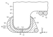
図4及び図5に示すように、端子電極50は、支持部22の表面に形成された下地層61と、下地層61を覆うめっき層62とを備えている。下地層61及びめっき層62は、それぞれ非磁性体よりなる。即ち、端子電極50は非磁性体である。
As shown in FIGS. 4 and 5, the
下地層61は、銀(Ag)を含むガラスの焼結体の層である。本実施形態では、下地層61の導電性材料は銀であるが、銀に限らず、銀パラジウム合金(Ag-Pd)などの非磁性の良導体である金属材料を用いることもできる。下地層61は、例えば銀粉末及びガラス粉末を含む樹脂である導電性ペーストの塗布焼き付けにより形成される。
The
めっき層62は、下地層61を覆う第1めっき層63と、第1めっき層63を覆う第2めっき層64とから構成されている。第1めっき層63は、銅(Cu)よりなり下地層61と隣り合う金属層である。第2めっき層64は、錫(Sn)よりなり第1めっき層63と隣り合う金属層である。第2めっき層64の材料は、錫以外に、金(Au)、パラジウム、金パラジウム合金(Au-Pd)などの非磁性の親はんだ性を有する金属材料を用いることもできる。これら第1めっき層63及び第2めっき層64は、例えば電解めっき法により形成される。なお、本実施形態の第1めっき層63は銅電極層に該当し、本実施形態の第2めっき層64は錫電極層に該当する。
The plating layer 62 is composed of a first plating layer 63 that covers the
第1めっき層63は、厚さ寸法Th1が10μm以上、30μm以下であることが好ましい。更に、第1めっき層63の厚さ寸法Th1は、15μm以上、20μm以下であることがより好ましい。例えば、本実施形態では、第1めっき層63の厚さ寸法Th1は17μmである。なお、第1めっき層63の厚さ寸法Th1は、その形成面である下地層61の表面を基準とした厚みである。但し、第1めっき層63の端部は、下地層61上を越える場合や、極端に薄くなる場合があるため、厚さ寸法Th1の測定対象とはならない。
The first plating layer 63 preferably has a thickness dimension Th1 of 10 μm or more and 30 μm or less. Further, the thickness dimension Th1 of the first plating layer 63 is more preferably 15 μm or more and 20 μm or less. For example, in the present embodiment, the thickness dimension Th1 of the first plating layer 63 is 17 μm. The thickness dimension Th1 of the first plating layer 63 is a thickness based on the surface of the
また、底面部電極51においては、第1めっき層63は第2めっき層64よりも厚さが厚い。更に、底面部電極51では、下地層61は第1めっき層63よりも厚さが薄い。
図1(a)に示すように、軸部21に巻回されたワイヤ70は、例えば円形状の断面を有する芯線と、芯線の表面を被覆する被覆材とを含む。芯線の材料としては、例えば銅や銀、その合金等の良導電性の金属材料を主成分としたものを用いることができる。被覆材の材料としては、例えばポリウレタンやポリエステル、ポリアミドイミド等の絶縁性の樹脂材料を用いることができる。ワイヤ70の両端部は、一対の端子電極50にそれぞれ接続されており、具体的には、ワイヤ70の芯線が端子電極50に接触又は一体化することによって、電気的に接続されている。
Further, in the
As shown in FIG. 1A, the
ワイヤ70は、軸部21に巻回された巻線部71と、端子電極50に接続された接続部72と、接続部72と巻線部71との間に掛け渡された渡り部73とを有している。接続部72は、端子電極50のうち、支持部22の底面36に形成された底面部電極51に接続されている。巻線部71の軸部21への巻回態様は、1層巻き、多層巻き、密接巻き、ピッチ巻きなど公知の巻回態様の何れであってもよい。例えば、本実施形態では、巻線部71は、軸部21に1層分隣接ターンが密接して巻回されている。巻線部71の巻回軸は長さ方向Ldと平行である。
The
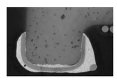
図1(a)、図4及び図5に示すように、ワイヤ70の端部と端子電極50とは、例えば、ヒータチップを用いた熱圧着により接続されている。底面部電極51の上にワイヤ70の端部(接続部72となる部分)を載せた後に、ヒータチップで加熱及び加圧することにより、ワイヤ70の端部と端子電極50とを接続することができる。具体的には、300~500℃の範囲の温度、好ましくは500℃に加熱されたヒータチップで、ワイヤ70の端部を底面部電極51に対して加圧する。これにより、ワイヤ70の端部(接続部72)では、被覆材が剥離され、露出した芯線が、底面部電極51において第2めっき層64に接続された状態となる。本実施形態では、第2めっき層64は錫よりなるためヒータチップの加熱により溶融し、ワイヤ70の端部は、ヒータチップの加熱により第2めっき層64内に押し込まれ、端子電極50に接続された状態となる。なお、接続方法はこれに限られず、各種公知の方法を用いることができる。
As shown in FIGS. 1 (a), 4 and 5, the end of the
なお、端面部電極52、内面部電極53及び側面部電極54では、第2めっき層64は、第1めっき層63よりも厚さが厚いことが好ましい。この場合、端面部電極52、内面部電極53及び側面部電極54のはんだ濡れ性が向上し、インダクタ部品10の回路基板への実装時において、実装はんだがフィレットをより高く形成し、回路基板に対するインダクタ部品10の固着力をより向上できる。
In the
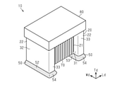
図2に示すように、インダクタ部品10は、更にカバー部材80を有している。なお、図1(a)及び図1(b)では、コア20及びワイヤ70を判り易くするため、カバー部材80を二点鎖線にて図示している。
As shown in FIG. 2, the
カバー部材80は、一対の支持部22の間に配設されて天面35側でワイヤ70を覆っている。具体的には、カバー部材80は、一方の支持部22の天面35から軸部21の上方を介して他方の支持部22の天面35に至るまで形成されている。カバー部材80の材料としては、例えば、エポキシ系などの樹脂材料を用いることができる。
The
カバー部材80は、例えばインダクタ部品10を回路基板に実装する際に、吸引ノズルによる吸着が確実に行えるようにする。また、カバー部材80は、吸引ノズルによる吸着時にワイヤ70に傷がつくことを防止する。なお、カバー部材80に金属磁性粉含有樹脂などの磁性材料を用いることで、インダクタ部品10のインダクタンス値(L値)を向上させることができる。一方、カバー部材80に磁性粉を含有しない樹脂などの非磁性材料を用いることで、磁性損失を低減し、インダクタ部品10のQ値を向上させることができる。なお、この場合、カバー部材80には酸化シリコン、硫酸バリウムなどのフィラーを含有させた樹脂を用いてもよい。
The
本実施形態の作用について説明する。
本実施形態のインダクタ部品10の端子電極50は非磁性体であるため、端子電極50が周囲の磁場に反応することが抑制される。従って、端子電極50を備えたインダクタ部品10を強磁場の環境で使用したとしても、端子電極50によって周囲の磁場が乱されることが抑制される。よって、例えば、インダクタ部品10をMRIで使用した場合、端子電極50に起因して撮影画像が乱れることが抑制される。
The operation of this embodiment will be described.
Since the
また、端子電極50が非磁性体であるため、インダクタ部品10が発生させる磁場が端子電極50によって乱されることが抑制される。例えば、従来のように端子電極にニッケルが含まれる場合、ニッケルは磁性材料であることから、ワイヤの巻線部に通電されることで発生する磁束が遮断されて渦電流損失などが発生し、Q値が低下するという問題がある。しかしながら、本実施形態のインダクタ部品10では、端子電極50は非磁性体であるため、同端子電極50によってワイヤ70にて形成されたコイルの磁界が遮断されることがなく、Q値の低下を抑制できる。
Further, since the
なお、支持部22がセラミックスよりなり、端子電極50が、支持部22の表面に形成された銀を含むガラスの焼結体である下地層61と、下地層61を覆うめっき層62とを備え、めっき層62が、銅よりなり下地層61を覆う銅電極層である第1めっき層63を含むことが好ましい。この場合、支持部22及び下地層61がともに焼結体であるため、支持部22と端子電極50との密着性を向上させることができる。更に、ワイヤ70の端部と端子電極50との接続時や、インダクタ部品10の実装時、実装後に端子電極50が加熱された場合、下地層61を覆うめっき層62の第1めっき層63によって、下地層61が溶解して流出することを抑制できる。従って、インダクタ部品10の耐熱性を向上させることが可能である。
The
また、銅電極層である第1めっき層63の厚さ寸法Th1が10μm以上であることが好ましい。これにより、ワイヤ70の端部と端子電極50とが熱圧着されたとしても、第1めっき層63によって下地層61が溶解して流出することをより確実に抑制できる。従って、インダクタ部品10の耐熱性をより向上できる。更に、インダクタ部品10をリフロー実装する場合には、リフロー実装を行う際の熱によって下地層61が溶解して流出することを第1めっき層63によって抑制できる。
Further, it is preferable that the thickness dimension Th1 of the first plating layer 63, which is a copper electrode layer, is 10 μm or more. As a result, even if the end portion of the
また、銅電極層である第1めっき層63の厚さ寸法Th1が30μm以下であることが好ましい。これにより、インダクタ部品10が端子電極50によって高背化し過ぎることや、一対の支持部22間の端子電極50の高さばらつきによるコプラナリティの低下を抑制できる。
Further, it is preferable that the thickness dimension Th1 of the first plating layer 63, which is a copper electrode layer, is 30 μm or less. As a result, it is possible to suppress the
また、端子電極50は、支持部22の底面36に形成された底面部電極51を有し、めっき層62は、錫よりなり銅電極層(第1めっき層63)を覆う錫電極層である第2めっき層64を含み、底面部電極51では、第1めっき層63は第2めっき層64よりも厚さが厚く、ワイヤ70の端部は、底面部電極51に接続されていることが好ましい。銅と錫とは合金を形成するため、錫よりなる第2めっき層64の厚さが銅よりなる第1めっき層63よりも厚いと、端子電極50が加熱された時に、第1めっき層63を構成する銅が錫よりなる第2めっき層64中に拡散されて第1めっき層63が極端に薄くなったり無くなったりする虞がある。すると、下地層61が流出してしまい、端子電極50がコア20の支持部22から剥離しやすくなってしまう。しかしながら、ワイヤ70の端部が接続される底面部電極51においては、第2めっき層64よりも第1めっき層63の厚さが厚い場合、ワイヤ70の端部と端子電極50とが熱圧着のために加熱された場合であっても、第1めっき層63が極端に薄くなったり無くなったりすることが抑制される。従って、下地層61が溶解して流出することを更に抑制できる。
Further, the
また、底面部電極51では、下地層61は第1めっき層63よりも厚さが薄いことが好ましい。これにより、底面36と直交する方向(即ち、高さ方向Td)に端子電極50が厚くなることを抑制でき、インダクタ部品10が端子電極50によって高背化し過ぎることや、一対の支持部22間の端子電極50の高さばらつきによるコプラナリティの低下を抑制できる。
Further, in the
本実施形態の効果について説明する。
(1)インダクタ部品10は、柱状の軸部21及び軸部21の両端に設けられた一対の支持部22を有するコア20と、一対の支持部22の各々に設けられた非磁性体の端子電極50と、軸部21に巻回され両端部がそれぞれ一対の支持部22の端子電極50に接続されたワイヤ70とを備えている。
The effect of this embodiment will be described.
(1) The
端子電極50は非磁性体であるため、端子電極50が周囲の磁場に反応することが抑制される。従って、周囲の磁場への影響を低減できる。また、端子電極50は非磁性体であるため、インダクタ部品10が発生させる磁場が端子電極50によって乱されることが抑制される。その結果、Q値の低下を抑制できる。
Since the
(2)支持部22はセラミックスよりなり、端子電極50は、支持部22の表面に形成された銀を含むガラスの焼結体である下地層61と、下地層61を覆うめっき層62とを備えることが好ましい。この場合、支持部22及び下地層61がともに焼結体であるため、支持部22と端子電極50との密着性を向上させることができる。
(2) The
(3)めっき層62は、銅よりなり下地層61を覆う銅電極層である第1めっき層63を含むことが好ましい。この場合、ワイヤ70の端部と端子電極50との接続時や、インダクタ部品10の実装時、実装後に端子電極50が加熱された場合、下地層61を覆うめっき層62の第1めっき層63によって、下地層61が溶解して流出することを抑制できる。その結果、端子電極50がコア20の支持部22から剥離することを抑制できる。従って、インダクタ部品10の耐熱性を向上させることができる。
(3) The plating layer 62 is preferably made of copper and preferably includes a first plating layer 63 which is a copper electrode layer covering the
(4)銅電極層である第1めっき層63の厚さ寸法Th1が10μm以上、30μm以下であることが好ましい。これにより、ワイヤ70の端部と端子電極50とが熱圧着されたとしても、第1めっき層63によって下地層61が溶解して流出することをより確実に抑制できる。その結果、端子電極50がコア20の支持部22から剥離することをより抑制できる。従って、インダクタ部品10の耐熱性をより向上できる。
(4) It is preferable that the thickness dimension Th1 of the first plating layer 63, which is a copper electrode layer, is 10 μm or more and 30 μm or less. As a result, even if the end portion of the
また、銅電極層である第1めっき層63の厚さ寸法Th1が30μm以下であると、インダクタ部品10が端子電極50によって高背化し過ぎることや、一対の支持部22間の端子電極50の高さばらつきによるコプラナリティの低下を抑制できる。
Further, when the thickness dimension Th1 of the first plating layer 63, which is a copper electrode layer, is 30 μm or less, the
(5)端子電極50は、支持部22の底面36に形成された底面部電極51を有し、めっき層62は、錫よりなり銅電極層(第1めっき層63)を覆う錫電極層である第2めっき層64を含み、底面部電極51では、第1めっき層63は第2めっき層64よりも厚さが厚く、ワイヤ70の端部は、底面部電極51に接続されていることが好ましい。
(5) The
銅と錫とは合金を形成するため、錫よりなる第2めっき層64の厚さが銅よりなる第1めっき層63よりも厚いと、端子電極50が加熱された時に、第1めっき層63を構成する銅が錫よりなる第2めっき層64中に拡散されて第1めっき層63が極端に薄くなったり無くなったりする虞がある。すると、下地層61が流出してしまい、端子電極50がコア20の支持部22から剥離しやすくなってしまう。しかしながら、ワイヤ70の端部が接続される底面部電極51においては、第2めっき層64よりも第1めっき層63の厚さが厚い場合、ワイヤ70の端部と端子電極50とが熱圧着のために加熱された場合であっても、第1めっき層63が極端に薄くなったり無くなったりすることが抑制される。従って、下地層61が溶解して流出することを更に抑制できる。その結果、端子電極50がコア20の支持部22から剥離することを更に抑制できる。よって、インダクタ部品10の耐熱性を更に向上できる。
Since copper and tin form an alloy, if the thickness of the second plating layer 64 made of tin is thicker than that of the first plating layer 63 made of copper, the first plating layer 63 is heated when the
(6)端子電極50は、支持部22の底面36に形成された底面部電極51を有し、底面部電極51では、下地層61は第1めっき層63よりも厚さが薄いことが好ましい。これにより、底面36と直交する方向に端子電極50が厚くなることを抑制でき、インダクタ部品10が端子電極50によって高背化し過ぎることや、一対の支持部22間の端子電極50の高さばらつきによるコプラナリティの低下を抑制できる。
(6) The
<変更例>
本実施形態は、以下のように変更して実施することができる。本実施形態及び以下の変更例は、技術的に矛盾しない範囲で互いに組み合わせて実施することができる。
<Change example>
This embodiment can be modified and implemented as follows. The present embodiment and the following modified examples can be implemented in combination with each other within a technically consistent range.
・上記実施形態に対し、端子電極50の形状を適宜変更してもよい。
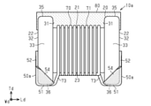
例えば、図6及び図7に示す巻線型インダクタ部品10aに備えられる端子電極50aは、一対の支持部22の互いに対向する内面31側の端部から支持部22における内面31と反対側の端面32側の端部に向かうほど高さが高い。なお、図6及び図7に示す例では、上記実施形態の構成と対応する構成に同一の符号を付している。端子電極50aは、上記実施形態の端子電極50と同様に非磁性体である。端子電極50aは、幅方向Wdから見て(即ち、図7に示す状態)、支持部22の内面31側の端部から側面部電極54における端面32側の端部まで徐々に高さが高くなり、端面部電極52において最も高さが高い。
-The shape of the
For example, the
このようにすると、端子電極50aは、支持部22の端面32を覆う部分の高さが高くなることにより表面積が増加する。この表面積の増加は、巻線型インダクタ部品10aの回路基板への実装時に、実装はんだが端面部電極52に沿って高くフィレットを形成することを可能にするため、回路基板に対する巻線型インダクタ部品10aの固着力がより向上する。特に、巻線型インダクタ部品10aが小型化されたとしても、固着力を確保しやすい。一方、端面部電極52の高さに対して、内面部電極53は高さを抑制することができるため、巻線型インダクタ部品10aの回路基板への実装時に、実装はんだが内面部電極53に沿って濡れ上がったとしても、巻線部71への実装はんだの付着を抑制することができる。また、支持部22の端面32を覆う部分の高さが高くなると、巻線部71が通電されることで軸部21に沿って発生する高密度の磁束を端子電極50が塞ぐ形となるが、同端子電極50aは非磁性体であるため、磁束の遮断によるQ値の低下を抑制できる。
In this way, the surface area of the
なお、図6及び図7に示す端子電極50aにおいて、端面32側の端部が最も高さが高くなるように形成されるのであれば、内面31側の端部から端面32側の端部に向かって一部低くなる部分があってもよい。
In the
また、上記実施形態の端子電極50において、端面部電極52、内面部電極53及び側面部電極54の高さを異ならせてもよい。また、内面部電極53及び側面部電極54の少なくとも一方の電極を備えない端子電極としてもよい。また、上記実施形態では、一対の支持部22に形成された端子電極50の形状を同じ形状としたが、異なる形状としてもよい。
Further, in the
・上記実施形態では、底面部電極51では、下地層61は第1めっき層63よりも厚さが薄い。しかしながら、底面部電極51において、下地層61の厚さを第1めっき層63の厚さ以上の厚さとしてもよい。
In the above embodiment, in the
・底面部電極51における第1めっき層63の厚さ及び第2めっき層64の厚さは上記実施形態のものに限らず、適宜変更してもよい。
・上記実施形態では、めっき層62は、第1めっき層63と第2めっき層64とから構成されている。しかしながら、めっき層62は、非磁性の金属材料よりなる1つ以上の金属層から構成されればよい。
The thickness of the first plating layer 63 and the thickness of the second plating layer 64 in the
-In the above embodiment, the plating layer 62 is composed of a first plating layer 63 and a second plating layer 64. However, the plating layer 62 may be composed of one or more metal layers made of a non-magnetic metal material.
・上記実施形態では、端子電極50は、下地層61とめっき層62とから構成されている。しかしながら、端子電極50は、非磁性体よりなるのであれば、その構成は上記実施形態のものに限らず適宜変更してもよい。
In the above embodiment, the
・上記実施形態に対し、カバー部材80の形状を適宜変更してもよい。例えば、カバー部材80は、支持部22の天面35を覆わず、一対の支持部22の間にのみ配設されたものであってもよい。このカバー部材80は、軸部21に巻回されたワイヤ70(巻線部71)を覆うように形成されるとともに、同カバー部材80の天面は、支持部22の天面35と面一な平面状をなす。
-The shape of the
また、上記実施形態においては、カバー部材80は、支持部22の間においては、軸部21の上部におけるワイヤ70のみを覆うように形成されたが、これと異なる構成であってもよい。例えば、カバー部材80は、軸部21の上部に加えて軸部21の両側面におけるワイヤ70を覆う形状であってもよい。また例えば、カバー部材80は、軸部21の底面上のワイヤ70も含む巻線部71の全体を覆う形状であってもよい。また、インダクタ部品10は必ずしもカバー部材80を備えなくてもよい。
Further, in the above embodiment, the
・上記実施形態に対し、コア20の形状を適宜変更してもよい。
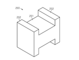
図8に示すコア200は、直方体状の軸部201と、軸部201の両端部の支持部202とを有している。支持部202は、軸部201と同じ幅に形成されるとともに、軸部201に対して上方及び下方に張り出すように形成されている。つまり、このコア200は、側面がH字状に形成されている。なお、図8に示すコア200は一例の概略であり、軸部201と支持部202の形状は適宜変更が可能である。
-The shape of the core 20 may be appropriately changed with respect to the above embodiment.
The
具体的には、コアの軸部は、円柱状や四角以外の多角柱状であってもよい。なお、柱状には錐台形状も含む。また、コアの支持部は、主面が正方形状などの他の多角形状や円形状、楕円状の鍔状であってもよい。なお、鍔状には、厚みが主面の各辺と比較して厚い形状、薄い形状、同程度の形状、何れも含む。更に、軸部と支持部とは一体に形成されず、別部材として形成されたものを接着剤等で接合したものであってもよい。 Specifically, the shaft portion of the core may be a columnar column or a polygonal column other than a square. The columnar shape also includes a frustum shape. Further, the support portion of the core may have another polygonal shape such as a square main surface, a circular shape, or an elliptical collar shape. The brim shape includes a shape having a thickness thicker than that of each side of the main surface, a thin shape, and a shape having the same thickness. Further, the shaft portion and the support portion may not be integrally formed, but may be formed as separate members and joined with an adhesive or the like.
10,10a…巻線型インダクタ部品、20,200…コア、21,201…軸部、22,202…支持部、31…内面、32…端面、36…底面、50,50a…端子電極、51…底面部電極、61…下地層、62…めっき層、63…銅電極層としての第1めっき層、64…錫電極層としての第2めっき層、70…ワイヤ、Th1…厚さ寸法。 10,10a ... Wind-wound inductor component, 20,200 ... Core, 21,201 ... Shaft, 22,202 ... Support, 31 ... Inner surface, 32 ... End face, 36 ... Bottom surface, 50, 50a ... Terminal electrode, 51 ... Bottom electrode, 61 ... Underlayer, 62 ... Plating layer, 63 ... First plating layer as copper electrode layer, 64 ... Second plating layer as tin electrode layer, 70 ... Wire, Th1 ... Thickness dimensions.
Claims (5)
一対の前記支持部の各々に設けられた非磁性体の端子電極と、
前記軸部に巻回され両端部がそれぞれ一対の前記支持部の前記端子電極に接続されたワイヤと、を備え、
前記支持部はセラミックスよりなり、
前記端子電極は、前記支持部の表面に形成された銀を含むガラスの焼結体である下地層と、前記下地層を覆うめっき層と、を備え、
前記めっき層は、銅よりなり前記下地層を覆う銅電極層と、錫よりなり前記銅電極層を覆う錫電極層と、を含み、
前記支持部は、前記軸部の長さ方向において前記軸部とは反対側を向いた端面と、前記端子電極が形成されている側の底面と、を有し
前記端子電極は、前記底面に形成された底面部電極と、前記端面に形成された端面部電極と、を有し、
前記底面部電極では、前記銅電極層は前記錫電極層よりも厚さが厚く、
前記端面部電極では、前記錫電極層は前記銅電極層よりも厚さが厚く、
前記ワイヤの端部は、前記底面部電極に接続されている
巻線型インダクタ部品。 A core having a columnar shaft portion and a pair of support portions provided at both ends of the shaft portion,
A non-magnetic terminal electrode provided on each of the pair of the support portions,
A wire wound around the shaft portion and having both ends connected to the terminal electrodes of the pair of the support portions, respectively, is provided .
The support is made of ceramics
The terminal electrode includes a base layer, which is a sintered body of silver-containing glass formed on the surface of the support portion, and a plating layer that covers the base layer.
The plating layer includes a copper electrode layer made of copper and covering the base layer, and a tin electrode layer made of tin and covering the copper electrode layer.
The support portion has an end surface facing the opposite side of the shaft portion in the length direction of the shaft portion, and a bottom surface on the side on which the terminal electrode is formed.
The terminal electrode has a bottom surface electrode formed on the bottom surface and an end face electrode formed on the end face thereof.
In the bottom electrode, the copper electrode layer is thicker than the tin electrode layer.
In the end face electrode, the tin electrode layer is thicker than the copper electrode layer.
The end of the wire is connected to the bottom electrode.
Winding inductor component.
一対の前記支持部の各々に設けられた非磁性体の端子電極と、
前記軸部に巻回され両端部がそれぞれ一対の前記支持部の前記端子電極に接続されたワイヤと、を備え、
前記支持部はセラミックスよりなり、
前記端子電極は、前記支持部の表面に形成された銀を含むガラスの焼結体である下地層と、前記下地層を覆うめっき層と、を備え、
前記めっき層は、銅よりなり前記下地層を覆う銅電極層と、錫よりなり前記銅電極層を覆う錫電極層と、を含み、
前記支持部は、前記軸部の長さ方向において前記軸部側を向いた内面と、前記端子電極が形成されている側の底面と、を有し
前記端子電極は、前記底面に形成された底面部電極と、前記内面に形成された内面部電極と、を有し、
前記底面部電極では、前記銅電極層は前記錫電極層よりも厚さが厚く、
前記内面部電極では、前記錫電極層は前記銅電極層よりも厚さが厚く、
前記ワイヤの端部は、前記底面部電極に接続されている
巻線型インダクタ部品。 A core having a columnar shaft portion and a pair of support portions provided at both ends of the shaft portion,
A non-magnetic terminal electrode provided on each of the pair of the support portions,
A wire wound around the shaft portion and having both ends connected to the terminal electrodes of the pair of the support portions, respectively, is provided .
The support is made of ceramics
The terminal electrode includes a base layer, which is a sintered body of silver-containing glass formed on the surface of the support portion, and a plating layer that covers the base layer.
The plating layer includes a copper electrode layer made of copper and covering the base layer, and a tin electrode layer made of tin and covering the copper electrode layer.
The support portion has an inner surface facing the shaft portion side in the length direction of the shaft portion and a bottom surface on the side on which the terminal electrode is formed.
The terminal electrode has a bottom surface electrode formed on the bottom surface and an inner surface electrode formed on the inner surface.
In the bottom electrode, the copper electrode layer is thicker than the tin electrode layer.
In the inner surface electrode, the tin electrode layer is thicker than the copper electrode layer.
The end of the wire is connected to the bottom electrode.
Winding inductor component.
Priority Applications (4)
| Application Number | Priority Date | Filing Date | Title |
|---|---|---|---|
| JP2018235718A JP6996486B2 (en) | 2018-12-17 | 2018-12-17 | Winding inductor component |
| US16/700,002 US11462353B2 (en) | 2018-12-17 | 2019-12-02 | Winding inductor component |
| CN201911273436.7A CN111326329B (en) | 2018-12-17 | 2019-12-12 | Wire wound inductor component |
| CN201922231436.2U CN211016734U (en) | 2018-12-17 | 2019-12-12 | Wound inductor component |
Applications Claiming Priority (1)
| Application Number | Priority Date | Filing Date | Title |
|---|---|---|---|
| JP2018235718A JP6996486B2 (en) | 2018-12-17 | 2018-12-17 | Winding inductor component |
Publications (2)
| Publication Number | Publication Date |
|---|---|
| JP2020098835A JP2020098835A (en) | 2020-06-25 |
| JP6996486B2 true JP6996486B2 (en) | 2022-01-17 |
Family
ID=71071840
Family Applications (1)
| Application Number | Title | Priority Date | Filing Date |
|---|---|---|---|
| JP2018235718A Active JP6996486B2 (en) | 2018-12-17 | 2018-12-17 | Winding inductor component |
Country Status (3)
| Country | Link |
|---|---|
| US (1) | US11462353B2 (en) |
| JP (1) | JP6996486B2 (en) |
| CN (2) | CN211016734U (en) |
Families Citing this family (2)
| Publication number | Priority date | Publication date | Assignee | Title |
|---|---|---|---|---|
| JP6996486B2 (en) * | 2018-12-17 | 2022-01-17 | 株式会社村田製作所 | Winding inductor component |
| US11657963B2 (en) * | 2020-09-15 | 2023-05-23 | Enphase Energy, Inc. | Transformer helix winding production |
Citations (2)
| Publication number | Priority date | Publication date | Assignee | Title |
|---|---|---|---|---|
| JP2004311755A (en) | 2003-04-08 | 2004-11-04 | Matsushita Electric Ind Co Ltd | Manufacturing method of chip inductor |
| JP2014209590A (en) | 2013-03-29 | 2014-11-06 | 太陽誘電株式会社 | Multilayer inductor |
Family Cites Families (10)
| Publication number | Priority date | Publication date | Assignee | Title |
|---|---|---|---|---|
| JP3552189B2 (en) | 1997-05-14 | 2004-08-11 | 株式会社村田製作所 | Electronic components with wires |
| JP3262107B2 (en) * | 1999-08-26 | 2002-03-04 | 株式会社村田製作所 | Coil component and method of manufacturing the same |
| JP4421436B2 (en) * | 2004-09-30 | 2010-02-24 | 太陽誘電株式会社 | Surface mount coil parts |
| TWI282564B (en) * | 2005-11-10 | 2007-06-11 | Yageo Corp | Surface mount device having a cushioning layer therein and the method of making the same |
| JP4582196B2 (en) * | 2008-05-29 | 2010-11-17 | Tdk株式会社 | Inductor component mounting structure |
| KR101804186B1 (en) * | 2014-05-30 | 2017-12-04 | 가부시키가이샤 무라타 세이사쿠쇼 | Method for manufacturing winding-wire coil component |
| US10102970B2 (en) * | 2014-08-29 | 2018-10-16 | Kyocera Corporation | Electronic component, inductor core member, and inductor |
| JP6695136B2 (en) * | 2015-12-11 | 2020-05-20 | 株式会社村田製作所 | Wirewound inductor |
| US11164692B2 (en) * | 2017-07-11 | 2021-11-02 | Tdk Corporation | Coil device |
| JP6996486B2 (en) * | 2018-12-17 | 2022-01-17 | 株式会社村田製作所 | Winding inductor component |
-
2018
- 2018-12-17 JP JP2018235718A patent/JP6996486B2/en active Active
-
2019
- 2019-12-02 US US16/700,002 patent/US11462353B2/en active Active
- 2019-12-12 CN CN201922231436.2U patent/CN211016734U/en not_active Expired - Fee Related
- 2019-12-12 CN CN201911273436.7A patent/CN111326329B/en active Active
Patent Citations (2)
| Publication number | Priority date | Publication date | Assignee | Title |
|---|---|---|---|---|
| JP2004311755A (en) | 2003-04-08 | 2004-11-04 | Matsushita Electric Ind Co Ltd | Manufacturing method of chip inductor |
| JP2014209590A (en) | 2013-03-29 | 2014-11-06 | 太陽誘電株式会社 | Multilayer inductor |
Also Published As
| Publication number | Publication date |
|---|---|
| CN211016734U (en) | 2020-07-14 |
| JP2020098835A (en) | 2020-06-25 |
| CN111326329B (en) | 2023-07-28 |
| US11462353B2 (en) | 2022-10-04 |
| CN111326329A (en) | 2020-06-23 |
| US20200194166A1 (en) | 2020-06-18 |
Similar Documents
| Publication | Publication Date | Title |
|---|---|---|
| US10347415B2 (en) | Coil component | |
| KR101607027B1 (en) | Chip electronic component and board having the same mounted thereon | |
| JP6959062B2 (en) | Coil parts | |
| CN109243778B (en) | Coil device | |
| JP7351177B2 (en) | ceramic electronic components | |
| US11222752B2 (en) | Ceramic electronic device | |
| CN111834082B (en) | Coil component and method for manufacturing coil component | |
| US10984943B2 (en) | Electronic device | |
| KR102745210B1 (en) | Coil component and electronic device | |
| CN111128513B (en) | Coil component and electronic device | |
| JP2018186157A (en) | Inductor | |
| JP2019024113A (en) | Chip electronic component and its mounting board | |
| JP6996486B2 (en) | Winding inductor component | |
| US20230395310A1 (en) | Coil component and method for manufacturing the same | |
| CN111834084B (en) | Coil component | |
| CN111834083B (en) | Coil component | |
| CN212084775U (en) | Wound inductor component | |
| CN212516757U (en) | Wound inductor component | |
| JP2023103038A (en) | Coil device | |
| JP7172971B2 (en) | WINDING CORE, COIL COMPONENT, AND COIL COMPONENT MANUFACTURING METHOD | |
| JP6460211B2 (en) | Coil component and manufacturing method thereof | |
| JP2016149490A (en) | Coil component and manufacturing method of the same | |
| JP6723690B2 (en) | Coated lead type electronic component and manufacturing method thereof |
Legal Events
| Date | Code | Title | Description |
|---|---|---|---|
| A621 | Written request for application examination |
Free format text: JAPANESE INTERMEDIATE CODE: A621 Effective date: 20200609 |
|
| A977 | Report on retrieval |
Free format text: JAPANESE INTERMEDIATE CODE: A971007 Effective date: 20210407 |
|
| A131 | Notification of reasons for refusal |
Free format text: JAPANESE INTERMEDIATE CODE: A131 Effective date: 20210427 |
|
| A521 | Request for written amendment filed |
Free format text: JAPANESE INTERMEDIATE CODE: A523 Effective date: 20210623 |
|
| TRDD | Decision of grant or rejection written | ||
| A01 | Written decision to grant a patent or to grant a registration (utility model) |
Free format text: JAPANESE INTERMEDIATE CODE: A01 Effective date: 20211116 |
|
| A61 | First payment of annual fees (during grant procedure) |
Free format text: JAPANESE INTERMEDIATE CODE: A61 Effective date: 20211129 |
|
| R150 | Certificate of patent or registration of utility model |
Ref document number: 6996486 Country of ref document: JP Free format text: JAPANESE INTERMEDIATE CODE: R150 |