JP6996449B2 - Communication device and communication method - Google Patents
Communication device and communication method Download PDFInfo
- Publication number
- JP6996449B2 JP6996449B2 JP2018152531A JP2018152531A JP6996449B2 JP 6996449 B2 JP6996449 B2 JP 6996449B2 JP 2018152531 A JP2018152531 A JP 2018152531A JP 2018152531 A JP2018152531 A JP 2018152531A JP 6996449 B2 JP6996449 B2 JP 6996449B2
- Authority
- JP
- Japan
- Prior art keywords
- slice
- information
- communication device
- slg
- slice information
- Prior art date
- Legal status (The legal status is an assumption and is not a legal conclusion. Google has not performed a legal analysis and makes no representation as to the accuracy of the status listed.)
- Active
Links
Images


Classifications
-
- H—ELECTRICITY
- H04—ELECTRIC COMMUNICATION TECHNIQUE
- H04L—TRANSMISSION OF DIGITAL INFORMATION, e.g. TELEGRAPHIC COMMUNICATION
- H04L12/00—Data switching networks
- H04L12/28—Data switching networks characterised by path configuration, e.g. LAN [Local Area Networks] or WAN [Wide Area Networks]
- H04L12/2854—Wide area networks, e.g. public data networks
- H04L12/2856—Access arrangements, e.g. Internet access
-
- H—ELECTRICITY
- H04—ELECTRIC COMMUNICATION TECHNIQUE
- H04L—TRANSMISSION OF DIGITAL INFORMATION, e.g. TELEGRAPHIC COMMUNICATION
- H04L12/00—Data switching networks
- H04L12/28—Data switching networks characterised by path configuration, e.g. LAN [Local Area Networks] or WAN [Wide Area Networks]
- H04L12/46—Interconnection of networks
- H04L12/4641—Virtual LANs, VLANs, e.g. virtual private networks [VPN]
-
- H—ELECTRICITY
- H04—ELECTRIC COMMUNICATION TECHNIQUE
- H04L—TRANSMISSION OF DIGITAL INFORMATION, e.g. TELEGRAPHIC COMMUNICATION
- H04L41/00—Arrangements for maintenance, administration or management of data switching networks, e.g. of packet switching networks
- H04L41/12—Discovery or management of network topologies
- H04L41/122—Discovery or management of network topologies of virtualised topologies, e.g. software-defined networks [SDN] or network function virtualisation [NFV]
-
- H—ELECTRICITY
- H04—ELECTRIC COMMUNICATION TECHNIQUE
- H04L—TRANSMISSION OF DIGITAL INFORMATION, e.g. TELEGRAPHIC COMMUNICATION
- H04L41/00—Arrangements for maintenance, administration or management of data switching networks, e.g. of packet switching networks
- H04L41/40—Arrangements for maintenance, administration or management of data switching networks, e.g. of packet switching networks using virtualisation of network functions or resources, e.g. SDN or NFV entities
-
- H—ELECTRICITY
- H04—ELECTRIC COMMUNICATION TECHNIQUE
- H04L—TRANSMISSION OF DIGITAL INFORMATION, e.g. TELEGRAPHIC COMMUNICATION
- H04L41/00—Arrangements for maintenance, administration or management of data switching networks, e.g. of packet switching networks
- H04L41/50—Network service management, e.g. ensuring proper service fulfilment according to agreements
- H04L41/5041—Network service management, e.g. ensuring proper service fulfilment according to agreements characterised by the time relationship between creation and deployment of a service
- H04L41/5051—Service on demand, e.g. definition and deployment of services in real time
-
- H—ELECTRICITY
- H04—ELECTRIC COMMUNICATION TECHNIQUE
- H04L—TRANSMISSION OF DIGITAL INFORMATION, e.g. TELEGRAPHIC COMMUNICATION
- H04L45/00—Routing or path finding of packets in data switching networks
- H04L45/02—Topology update or discovery
- H04L45/021—Ensuring consistency of routing table updates, e.g. by using epoch numbers
Landscapes
- Engineering & Computer Science (AREA)
- Computer Networks & Wireless Communication (AREA)
- Signal Processing (AREA)
- Computer Security & Cryptography (AREA)
- Data Exchanges In Wide-Area Networks (AREA)
Description
本発明は、通信装置および通信方法に関する。 The present invention relates to a communication device and a communication method.
トラヒック、モビリティ、容量、ユーザ数、あるいは遅延時間等の多様なサービス要件に対応したネットワークサービスを提供するため、ネットワークスライス(以下、スライスとも記す。)と呼ばれる技術が提案されている(非特許文献1参照)。ネットワークスライスとは、共通的なネットワークインフラから、要件に応じた複数の論理ネットワークを切り出して、独立した管理を行う技術である。 In order to provide network services that meet various service requirements such as traffic, mobility, capacity, number of users, and delay time, a technique called network slice (hereinafter, also referred to as slice) has been proposed (non-patent document). See 1). Network slicing is a technology that cuts out multiple logical networks according to requirements from a common network infrastructure and manages them independently.
従来、ネットワークスライスは、オーケストレーションと呼ばれる制御装置の制御により実現されている。 Conventionally, the network slice is realized by the control of a control device called orchestration.
しかしながら、オーケストレーションを設置すると、複数のネットワークスライスを構成する全装置がオーケストレーションから制御される必要があり、全装置とオーケストレーションとのリンクが必要となる。オーケストレーション設置の費用は、大規模なシステムでは按分されるので影響が小さいが、中規模以下のシステムではシステム全体のコストに対する割合が高くなり影響が大きい。また、オーケストレーションの故障時の離礁範囲が大きい。 However, when an orchestration is installed, all the devices that make up a plurality of network slices need to be controlled from the orchestration, and a link between all the devices and the orchestration is required. The cost of installing an orchestration has a small impact because it is apportioned in a large-scale system, but in a medium-sized or smaller system, the ratio to the cost of the entire system is high and the impact is large. In addition, the reef range is large when the orchestration fails.
本発明は、上記に鑑みてなされたものであって、オーケストレーションを設置することなく、共通的なネットワークインフラから、要件に応じた複数の論理ネットワークを切り出して、独立した管理を行えるネットワークスライスを構築することを目的とする。 The present invention has been made in view of the above, and is a network slice capable of cutting out a plurality of logical networks according to requirements from a common network infrastructure and managing them independently without installing an orchestration. The purpose is to build.
上述した課題を解決し、目的を達成するために、本発明に係る通信装置は、所定の要件を満たす論理ネットワークであるネットワークスライスごとに配置され、該ネットワークスライスと、ユーザ端末が接続する仮想CPEまたは他のネットワークスライスとを接続する通信装置であって、自装置が属するネットワークスライスの情報であるスライス情報と、他の通信装置のスライス情報を集約したテーブルとを記憶する記憶部と、隣接する通信装置から他の通信装置のスライス情報を受信した場合に、該スライス情報を用いて前記テーブルを更新するテーブル作成部と、受信した前記スライス情報に自装置のスライス情報を付加して、隣接する他の通信装置に送信する送信部と、を備えることを特徴とする。 In order to solve the above-mentioned problems and achieve the object, the communication device according to the present invention is arranged for each network slice which is a logical network satisfying a predetermined requirement, and the network slice and the virtual CPE to which the user terminal is connected are connected. Alternatively, it is a communication device that connects to another network slice, and is adjacent to a storage unit that stores slice information that is information on the network slice to which the own device belongs and a table that aggregates slice information of other communication devices. When the slice information of another communication device is received from the communication device, the table creation unit that updates the table using the slice information and the slice information of the own device are added to the received slice information and adjacent to each other. It is characterized by including a transmission unit for transmitting to another communication device.
本発明によれば、オーケストレーションを設置することなく、共通的なネットワークインフラから、要件に応じた複数の論理ネットワークを切り出して、独立した管理を行えるネットワークスライスを構築することができる。 According to the present invention, it is possible to cut out a plurality of logical networks according to requirements from a common network infrastructure and construct a network slice that can be independently managed without installing an orchestration.
以下、図面を参照して、本発明の実施形態を詳細に説明する。なお、この実施形態により本発明が限定されるものではない。また、図面の記載において、同一部分には同一の符号を付して示している。 Hereinafter, embodiments of the present invention will be described in detail with reference to the drawings. The present invention is not limited to this embodiment. Further, in the description of the drawings, the same parts are indicated by the same reference numerals.
[ネットワークスライス]
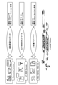
まず、図1は、ネットワークスライスを説明するための説明図である。ネットワークスライスは、物理ネットワークインフラから、要件に応じた複数の論理ネットワークを切り出して、独立した管理を行う技術である。
[Network slice]
First, FIG. 1 is an explanatory diagram for explaining a network slice. Network slice is a technology that cuts out multiple logical networks according to requirements from the physical network infrastructure and manages them independently.
例えば、図1に示すように、自動車等の遠隔操縦のためのネットワークスライスとして、遅延10ms以下、帯域10Mbps/セッション保障等の要件を満たす超低遅延ネットワークが切り出される。また、IoT(Internet of Things)や機器間(M2M、Machine to Machine)接続のためのネットワークスライスとして、遅延・帯域はベストエフォート(BE)、かつセキュリティ機能を要件として満たすIoT/M2M用ネットワークが切り出される。また、ゲームや動画視聴のためのネットワークスライスとして、遅延はベストエフォート、帯域1Gbps/セッション保証等の要件を満たす大容量ネットワークが切り出される。
For example, as shown in FIG. 1, as a network slice for remote control of an automobile or the like, an ultra-low delay network satisfying requirements such as a delay of 10 ms or less and a bandwidth of 10 Mbps / session guarantee is cut out. In addition, as a network slice for IoT (Internet of Things) and device-to-device (M2M, Machine to Machine) connections, an IoT / M2M network that meets the requirements of best effort (BE) for delay and bandwidth and security functions has been cut out. Is done. Further, as a network slice for watching a game or a moving image, a large-capacity network satisfying the requirements such as best effort for delay and
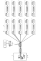
次に、図2は、本実施形態に係る通信装置を含むシステムの構成を例示する模式図である。図2に示すように、ユーザ端末1は、仮想化基盤上で実現されたCPE(Customer Premises Equipment)であるvCPE(仮想CPE)2に対して、接続を要求する。
Next, FIG. 2 is a schematic diagram illustrating the configuration of the system including the communication device according to the present embodiment. As shown in FIG. 2, the
vCPE2は、OSS(Operation Support System)やBSS(Business Support System)の認証サーバ3から、ユーザのSLA(Service Level Agreement)情報や必要なNFV(Network Functions Virtualization)情報等のユーザの要件を取得する。そして、vCPE2は、ユーザの要件に応じたスライス4に、ユーザ端末1のトラヒックを転送する。
The vCPE 2 acquires the user's requirements such as the user's SLA (Service Level Agreement) information and necessary NFV (Network Functions Virtualization) information from the
各スライス4には、SLG(Slice Gateway、スライスゲートウェイ)10が配置され、このSLG10が、vCPE2とスライス4、あるいはスライス4間を接続する。
An SLG (Slice Gateway) 10 is arranged in each
本実施形態の通信装置は、SLG10に実装される。SLG10は、所定の要件を満たすスライス4ごとに配置され、このスライス4と、vCPE2または他のスライス4とを接続する。また、SLG10は、後述する通信処理により、自律的にスライス4間を接続して、ユーザの要件に応じたスライス4に、ユーザ端末1のトラヒックを転送する。
The communication device of this embodiment is mounted on the SLG10. The SLG10 is arranged for each
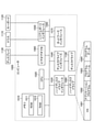
[SLGの構成]
次に、図3は、本実施形態の通信装置の概略構成を例示する模式図である。図3に示すように、本実施形態に係る通信装置であるSLG10は、CPU(Central Processing Unit)やNP(Network Processor)やFPGA(Field Programmable Gate Array)等で実現された物理リソース上に、仮想化して構築される。
[SLG configuration]
Next, FIG. 3 is a schematic diagram illustrating a schematic configuration of the communication device of the present embodiment. As shown in FIG. 3, the SLG10, which is a communication device according to the present embodiment, is virtual on a physical resource realized by a CPU (Central Processing Unit), an NP (Network Processor), an FPGA (Field Programmable Gate Array), or the like. It is constructed by being transformed into.
SLG10は、メモリに記憶された処理プログラムを実行することにより、図3に例示するように、SLG(VNF(Virtual Network Function))と、これに対応するSLG管理部(EM(Element Manager))、スライス振分機能等(VNF)と、これに対応する振り分け機能等管理部(EM)として機能する。 By executing the processing program stored in the memory, the SLG 10 has an SLG (VNF (Virtual Network Function)) and a corresponding SLG management unit (EM (Element Manager)), as illustrated in FIG. It functions as a slice distribution function (VNF) and a corresponding distribution function management unit (EM).
ここで、SLG(VNF)は、ゲートウェイとして、自装置が属するスライス4と、vCPE2または他のスライス4とを接続する。また、スライス振分機能部(VNF)は、ユーザの要件に応じたスライス4に、ユーザ端末1のトラヒックを転送する。
Here, the SLG (VNF) connects the
また、SLG10は、テーブル作成部11a、SLG情報送信部11b、トポロジ作成部11c、スライス選定部11d、スライス情報管理部11e、スライス故障管理部11f、スライス測定部11gおよびタグ管理部11hとして機能する。
Further, the SLG10 functions as a
また、SLG10は、RAM、フラッシュメモリ等の半導体メモリ素子上に構築された記憶部を備え、SLG情報12a、SLGテーブル12bおよびトポロジマップ12cを記憶する。
Further, the SLG 10 includes a storage unit built on a semiconductor memory element such as a RAM or a flash memory, and stores the SLG information 12a, the SLG table 12b, and the
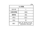
ここで、図4は、スライス情報のデータ構成を例示する図である。スライス情報すなわちSLG情報12aとは、SLG10が属するスライス4の情報である。例えば、図4に例示するように、SLG情報12aは、SLG-ID、全保有帯域、残帯域、メモリ、CPU等を含む。SLG-IDは、SLG10を識別する情報である。全保有帯域は、SLG10の配下の全装置の通信帯域の合計を表す。残帯域は、全保有帯域と配下の装置の使用中の帯域(使用帯域)との差を表す。メモリ、CPUは、配下の装置の性能を表す。
Here, FIG. 4 is a diagram illustrating a data structure of slice information. The slice information, that is, the SLG information 12a is the information of the
また、SLG情報12aは、NFVを含む。NFVは、SLG10が属するスライス4が保有する能力を表す。NFVとしては、例えば、DPI(Deep Packet Inspection)、AI、IoTサーバ制御、オプティマイズ、トランスコーディング等が例示される。
Further, the SLG information 12a includes NFV. NFV represents the ability possessed by
後述するスライス情報管理部11eが、定期的に、配下の装置の情報を収集しSLG情報12aとして管理する。
The slice
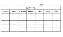
図5は、テーブルのデータ構成を例示する図である。テーブルすなわちSLGテーブル12bは、図5に示すように、各SLG10のSLG情報12aが集約されたものである。後述するように、テーブル作成部11aが、定期的に、SLGテーブル12bを更新する処理を行って、最新の状態を保持している。
FIG. 5 is a diagram illustrating the data structure of the table. As shown in FIG. 5, the table, that is, the SLG table 12b is a collection of SLG information 12a of each SLG10. As will be described later, the
図3の説明に戻る。テーブル作成部11aは、隣接するSLG10から他のSLG10のSLG情報12aを受信した場合に、該SLG情報12aを用いてSLGテーブル12bを更新する。
Returning to the description of FIG. When the
また、SLG情報送信部11bは、送信部として機能する。すなわち、SLG情報送信部11bは、受信したSLG情報12aに自装置のSLG情報12aを付加して、隣接する他のSLG10に送信する。 Further, the SLG information transmission unit 11b functions as a transmission unit. That is, the SLG information transmission unit 11b adds the SLG information 12a of its own device to the received SLG information 12a and transmits it to another adjacent SLG10.
具体的には、SLG情報送信部11bは、隣接するSLG10から、複数のSLG情報12aを受信した場合に、受信したSLG情報12aの最後尾等に自装置のSLG情報12aを付加して、隣接する他のSLG10に転送する。また、テーブル作成部11aは、隣接するSLG10から受信した複数のSLG情報12aを用いて、SLGテーブル12bを更新する。これにより、各SLG10は、隣接するSLG10を介して接続する全てのSLG10のSLG情報12aを集約して、SLGテーブル12bとして管理することができる。
Specifically, when the SLG information transmission unit 11b receives a plurality of SLG information 12a from the adjacent SLG10, the SLG information transmission unit 11b adds the SLG information 12a of its own device to the tail end of the received SLG information 12a and is adjacent to the SLG information transmission unit 11b. Transfer to another SLG10. Further, the
トポロジ作成部11cは、受信したSLG情報12aを用いて、他のSLG10との位置関係を表すトポロジマップ12cを作成する。すなわち、トポロジ作成部11cは、受信した複数のSLG情報12aにより、例えば、数リンク先に存在するSLG10とそのSLG情報12aとがわかる。これにより、トポロジ作成部11cは、例えば、自装置を中心とした他のSLG10との位置関係を表すトポロジマップ12cを作成する。
The topology creation unit 11c creates a
なお、SLG情報12aがNFVの情報を含む場合には、SLG10は、SLG情報12aとトポロジマップ12cとを用いて、NFVの所在を表すNFVマップを作成することができる。
When the SLG information 12a includes the NFV information, the
スライス選定部11dは、選定部として機能する。すなわち、スライス選定部11dは、vCPE2からユーザ端末1の接続の要求を受信した場合に、SLGテーブル12bおよびトポロジマップ12cを用いて、ユーザの要件に応じた宛先のSLG10を選定する。
The slice selection unit 11d functions as a selection unit. That is, when the slice selection unit 11d receives the connection request of the
また、スライス選定部11dは、SLG情報12aがNFVの情報を含む場合には、ユーザの要件に含まれるNFVに応じて、宛先のSLG10を選定する。 Further, when the SLG information 12a includes the NFV information, the slice selection unit 11d selects the destination SLG10 according to the NFV included in the user's requirement.
また、スライス選定部11dは、SLGテーブル12bに宛先に該当するSLG10のSLG情報がない場合に、新規のSLG10を選定してリソース確保の要求を送信する。そして、スライス選定部11dは、該新規のSLG10への要求を中継するSLG10を介して、該SLG10のSLG情報12aが付加された、要求に対する応答を受信する。中継するSLG10は複数でもよい。 Further, when the SLG table 12b does not have the SLG information of the SLG10 corresponding to the destination, the slice selection unit 11d selects a new SLG10 and transmits a request for securing resources. Then, the slice selection unit 11d receives the response to the request to which the SLG information 12a of the SLG10 is added via the SLG10 that relays the request to the new SLG10. There may be a plurality of SLG10s to be relayed.
この場合に、テーブル作成部11aは、受信した各SLG10のSLG情報12aを用いてSLGテーブル12bを更新する。これにより、SLG10は、ユーザ端末1の通信の際にも、SLGテーブル12bを更新することが可能である。
In this case, the
なお、スライス選定部11dは、SLG10を選定する際に、スライス情報管理部11e、スライス故障管理部11f、およびスライス測定部11gから取得した情報を参照する。
The slice selection unit 11d refers to the information acquired from the slice
スライス情報管理部11eは、自装置の配下の通信可能な全装置の情報を定期的に取得して、SLG情報12aとして管理する。スライス故障管理部11fは、自装置の配下の全装置に関する故障情報を管理する。例えば、スライス故障管理部11fは、故障情報を取得して、他のSLG10に通知する。
The slice
スライス測定部11gは、他のスライス4の状態を測定する。例えば、スライス測定部11gは、新規のスライス4にパケットを送信して返送に要する時間を測定し、遅延情報等を取得する。
The slice measuring unit 11g measures the state of the
タグ管理部11hは、スライス選定部11dが選定したSLG10に宛てて送信するパケットに、ユーザの要件を表すタグを付与する。例えば、タグ管理部11hは、SLA情報の値であるSLIに関するタグを付与する。 The tag management unit 11h attaches a tag representing the user's requirement to the packet transmitted to the SLG10 selected by the slice selection unit 11d. For example, the tag management unit 11h attaches a tag related to SLI, which is a value of SLA information.
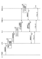
ここで、図6は、通信装置の処理を説明するための説明図である。図6には、vCPE2から受信した接続要求の宛先に該当するSLG10のSLG情報が、SLGテーブル12bにない場合について例示されている。
Here, FIG. 6 is an explanatory diagram for explaining the processing of the communication device. FIG. 6 illustrates a case where the SLG information of the
まず、vCPE2は、ユーザ端末1の接続要求を受信した場合に(ステップS1)、認証サーバ3に問い合わせ、ユーザに関するSLA情報や必要なNFV情報を取得して(ステップS2)、ユーザの要件を確認する。そして、vCPE2は、ユーザの要件に応じたスライス4の確保を要求するメッセージをSLG10に送信する(ステップS3)。
First, when vCPE2 receives the connection request of the user terminal 1 (step S1), it inquires of the
vCPE2からスライス4の確保の要求を受信したSLG10では、スライス選定部11dが、SLGテーブル12bを参照し、宛先のSLG10を選定する。ユーザの要件にNFVが含まれる場合には、NFVに応じたSLG10を宛先として選定する。
In the SLG10 that has received the request for securing the
SLGテーブル12bに宛先に該当するSLG10のSLG情報がない場合、スライス選定部11dは、スライス情報管理部11e、スライス故障管理部11f、およびスライス測定部11gから取得した情報を参照して、新規のSLG10を宛先として選定する(ステップS4)。
When there is no SLG information of the SLG10 corresponding to the destination in the SLG table 12b, the slice selection unit 11d refers to the information acquired from the slice
SLG10は、新規の宛先SLGに対して、中継SLGを介してリソース確保の要求を送信する。SLG10は、ユーザの要件にNFVが含まれる場合には、NFV確保の要求を送信する(ステップS5)。 The SLG10 transmits a resource reservation request to the new destination SLG via the relay SLG. If the user's requirements include NFV, the SLG10 sends a request to secure NFV (step S5).
宛先SLGは、スライス確保を完了した場合に(ステップS6)、中継SLGに確保完了のメッセージを送信する(ステップS7)。宛先SLGは、NFV確保を要求された場合には、NFV確保を完了した際に、中継SLGに確保完了のメッセージを送信する。 When the destination SLG completes the slice reservation (step S6), the destination SLG sends a message of the reservation completion to the relay SLG (step S7). When the destination SLG is requested to secure NFV, the destination SLG sends a message of securing completion to the relay SLG when the securing of NFV is completed.
確保完了のメッセージを受信した中継SLGは、要求元のSLG10に宛てて確保完了のメッセージを送信する。その際に、中継SLGは、自装置のSLG情報12aを付加する(ステップS8)。 The relay SLG that has received the reservation completion message sends the reservation completion message to the requesting SLG10. At that time, the relay SLG adds the SLG information 12a of its own device (step S8).
確保完了のメッセージを受信した要求元のSLG10は、vCPE2に確保完了のメッセージを送信する(ステップS9)。また、要求元のSLG10は、受信した中継SLGのSLG情報12aを用いて、SLGテーブル12bを更新する。このように、各SLG10は、ユーザ端末1の通信の際にもSLGテーブル12bを更新することができる。
Upon receiving the reservation completion message, the requesting SLG10 transmits the reservation completion message to vCPE2 (step S9). Further, the requesting SLG10 updates the SLG table 12b using the received SLG information 12a of the relay SLG. In this way, each
その後、vCPE2がSLG10に送信したユーザ端末1のトラヒックが、中継SLGを経由して宛先SLGに送信される(ステップS10)。なお、中継SLGは1台に限定されず、複数台あってもよい。
After that, the traffic of the
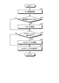
[通信処理]
次に、図7および図8は、通信処理手順を例示するフローチャートである。図7は、ユーザ端末1の通信に先立って、予めSLGテーブル12bを作成する通信処理手順を示す。図7に示すフローチャートは、例えば、所定の間隔で定期的に、あるいは、オペレータが指示したタイミングで開始される。
[Communication processing]
Next, FIGS. 7 and 8 are flowcharts illustrating the communication processing procedure. FIG. 7 shows a communication processing procedure for creating the SLG table 12b in advance prior to the communication of the
まず、テーブル作成部11aが、隣接するSLG10から他のSLG10のSLG情報12aを受信した場合に(ステップS11)、該SLG情報12aのSLG-IDが、SLGテーブル12bに登録されているか否かを確認する(ステップS12)。登録されていない場合には(ステップS12,No)、テーブル作成部11aは、このSLG-IDの該SLG情報12aを、SLGテーブル12bに登録する(ステップS13)。
First, when the
一方、登録されている場合には(ステップS12,Yes)、テーブル作成部11aは、SLGテーブル12bのSLG情報との差分があるかないかを確認する(ステップS14)。差分がある場合には(ステップS14,Yes)、テーブル作成部11aは、受信したSLG情報12aを用いてSLGテーブル12bを更新する(ステップS15)。
On the other hand, if it is registered (step S12, Yes), the
一方、差分がない場合には(ステップS14,No)、テーブル作成部11aは、SLGテーブル12bの作成を完了する(ステップS16)。
On the other hand, when there is no difference (step S14, No), the
このように、各SLG10は、隣接するSLG10を介して接続する全てのSLG10のSLG情報12aを集約して、SLGテーブル12bとして管理する。これにより、SLGテーブル12bを最新の状態に保持している。 In this way, each SLG10 aggregates the SLG information 12a of all the SLG10s connected via the adjacent SLG10 and manages them as the SLG table 12b. This keeps the SLG table 12b up to date.
また、図8は、ユーザ端末1の通信開始時にSLGテーブル12bを更新する通信処理手順を示す。図8に示すフローチャートは、ユーザ端末1の接続要求をvCPE2が受信したタイミングで開始される。
Further, FIG. 8 shows a communication processing procedure for updating the SLG table 12b at the start of communication of the
SLG10が、vCPE2からユーザの要件を含むスライス4確保の要求を受信した場合に(ステップS21)、スライス選定部11dが、宛先がSLGテーブル12bに登録済みの既存のスライス4か否かを確認する(ステップS22)。宛先がSLGテーブル12bに登録済みの場合には(ステップS22、Yes)、スライス選定部11dは、隣接するSLG10へ、ユーザ端末1のトラヒックを送信する(ステップS26)。
When the SLG10 receives a request for securing the
一方、宛先がSLGテーブル12bに登録されていない場合には(ステップS22、No)、スライス選定部11dは、ユーザの要件に応じたNFVを選定し(ステップS23)、SLIに応じたSLG10を宛先SLGとして選定する(ステップS24)。 On the other hand, when the destination is not registered in the SLG table 12b (step S22, No), the slice selection unit 11d selects the NFV according to the user's requirement (step S23), and the destination is the SLG10 according to the SLI. Select as SLG (step S24).
また、テーブル作成部11aは、宛先SLGへの要求を中継する中継SLGが、応答を中継する際に付加した自装置のSLG情報12aを用いて、SLGテーブル12bを更新する。
Further, the
また、タグ管理部11hが、SLIに関するタグを付加して(ステップS25)、隣接するSLG10へ、ユーザ端末1のトラヒックを送信する(ステップS26)。
Further, the tag management unit 11h adds a tag related to SLI (step S25), and transmits the traffic of the
以上、説明したように、本実施形態のSLG10では、テーブル作成部11aが、隣接するSLG10から他のSLG10のSLG情報12aを受信した場合に、該SLG情報12aを用いてSLGテーブル12bを更新する。また、SLG情報送信部11bが、受信したSLG情報12aに自装置のSLG情報12aを付加して、隣接する他のSLG10に送信する。
As described above, in the SLG10 of the present embodiment, when the
これにより、SLG10は、隣接するSLG10を介して接続する全てのSLG10のSLG情報12aを集約して、SLGテーブル12bとして管理する。したがって、SLG10は、SLGテーブル12bを用いて自律的にスライス4間を接続して、ユーザの要件に応じたスライス4にユーザ端末1のトラヒックを転送することができる。
As a result, the
具体的には、トポロジ作成部11cが、受信したSLG情報12aを用いて、他のSLG10との位置関係を表すトポロジマップ12cを作成する。また、スライス選定部11dが、vCPE2からユーザ端末1の接続の要求を受信した場合に、SLGテーブル12bおよびトポロジマップ12cを用いて、ユーザの要件に応じた宛先のSLG10を選定する。
Specifically, the topology creation unit 11c creates a
このように、本実施形態のSLG10によれば、オーケストレーションを設置することなく、共通的なネットワークインフラから、要件に応じた複数の論理ネットワークを切り出して、独立した管理を行えるネットワークスライスを構築することができる。 As described above, according to the SLG10 of the present embodiment, a plurality of logical networks according to the requirements are cut out from the common network infrastructure without installing an orchestration, and a network slice that can be independently managed is constructed. be able to.
また、スライス選定部11dは、SLG情報12aがNFVの情報を含む場合には、ユーザの要件に含まれるNFVに応じて、宛先のSLG10を選定する。これにより、SLG10は、ユーザ端末1のトラヒックを適切なNFVの処理を行うネットワークスライスに振り分けることができる。
Further, when the SLG information 12a includes the NFV information, the slice selection unit 11d selects the destination SLG10 according to the NFV included in the user's requirement. As a result, the
また、スライス選定部11dは、SLGテーブル12bに宛先に該当するSLG10のSLG情報がない場合に、新規のSLG10を選定してリソース確保の要求を送信する。そして、スライス選定部11dは、該新規のSLG10への要求を中継するSLG10を介して、該SLG10のSLG情報12aが付加された、要求に対する応答を受信する。この場合に、テーブル作成部11aは、受信した各SLG10のSLG情報12aを用いてSLGテーブル12bを更新する。これにより、SLG10は、ユーザ端末1の通信の際にも、SLGテーブル12bを更新することが可能である。
Further, when the SLG table 12b does not have the SLG information of the SLG10 corresponding to the destination, the slice selection unit 11d selects a new SLG10 and transmits a request for securing resources. Then, the slice selection unit 11d receives the response to the request to which the SLG information 12a of the SLG10 is added via the SLG10 that relays the request to the new SLG10. In this case, the
[プログラム]
上記実施形態に係るSLG10が実行する処理をコンピュータが実行可能な言語で記述したプログラムを作成することもできる。一実施形態として、SLG10は、パッケージソフトウェアやオンラインソフトウェアとして上記の通信処理を実行する通信プログラムを所望のコンピュータにインストールさせることによって実装できる。例えば、上記の通信プログラムを情報処理装置に実行させることにより、情報処理装置をSLG10として機能させることができる。ここで言う情報処理装置には、デスクトップ型またはノート型のパーソナルコンピュータが含まれる。また、その他にも、情報処理装置にはスマートフォン、携帯電話機等の移動体通信端末、さらには、PDA(Personal Digital Assistants)等のスレート端末などがその範疇に含まれる。また、SLG10の機能を、クラウドサーバに実装してもよい。
[program]
It is also possible to create a program in which the processing executed by the
図9は、通信プログラムを実行するコンピュータの一例を示す図である。コンピュータ1000は、例えば、メモリ1010と、CPU1020と、ハードディスクドライブインタフェース1030と、ディスクドライブインタフェース1040と、シリアルポートインタフェース1050と、ビデオアダプタ1060と、ネットワークインタフェース1070とを有する。これらの各部は、バス1080によって接続される。
FIG. 9 is a diagram showing an example of a computer that executes a communication program. The
メモリ1010は、ROM(Read Only Memory)1011およびRAM1012を含む。ROM1011は、例えば、BIOS(Basic Input Output System)等のブートプログラムを記憶する。ハードディスクドライブインタフェース1030は、ハードディスクドライブ1031に接続される。ディスクドライブインタフェース1040は、ディスクドライブ1041に接続される。ディスクドライブ1041には、例えば、磁気ディスクや光ディスク等の着脱可能な記憶媒体が挿入される。シリアルポートインタフェース1050には、例えば、マウス1051およびキーボード1052が接続される。ビデオアダプタ1060には、例えば、ディスプレイ1061が接続される。
The
ここで、ハードディスクドライブ1031は、例えば、OS1091、アプリケーションプログラム1092、プログラムモジュール1093およびプログラムデータ1094を記憶する。上記実施形態で説明した各情報は、例えばハードディスクドライブ1031やメモリ1010に記憶される。
Here, the hard disk drive 1031 stores, for example, the
また、通信プログラムは、例えば、コンピュータ1000によって実行される指令が記述されたプログラムモジュール1093として、ハードディスクドライブ1031に記憶される。具体的には、上記実施形態で説明したSLG10が実行する各処理が記述されたプログラムモジュール1093が、ハードディスクドライブ1031に記憶される。
Further, the communication program is stored in the hard disk drive 1031 as, for example, a
また、通信プログラムによる情報処理に用いられるデータは、プログラムデータ1094として、例えば、ハードディスクドライブ1031に記憶される。そして、CPU1020が、ハードディスクドライブ1031に記憶されたプログラムモジュール1093やプログラムデータ1094を必要に応じてRAM1012に読み出して、上述した各手順を実行する。
Further, the data used for information processing by the communication program is stored as
なお、通信プログラムに係るプログラムモジュール1093やプログラムデータ1094は、ハードディスクドライブ1031に記憶される場合に限られず、例えば、着脱可能な記憶媒体に記憶されて、ディスクドライブ1041等を介してCPU1020によって読み出されてもよい。あるいは、通信プログラムに係るプログラムモジュール1093やプログラムデータ1094は、LANやWAN(Wide Area Network)等のネットワークを介して接続された他のコンピュータに記憶され、ネットワークインタフェース1070を介してCPU1020によって読み出されてもよい。
The
以上、本発明者によってなされた発明を適用した実施形態について説明したが、本実施形態による本発明の開示の一部をなす記述および図面により本発明は限定されることはない。すなわち、本実施形態に基づいて当業者等によりなされる他の実施形態、実施例および運用技術等は全て本発明の範疇に含まれる。 Although the embodiment to which the invention made by the present inventor is applied has been described above, the present invention is not limited by the description and the drawings which form a part of the disclosure of the present invention according to the present embodiment. That is, other embodiments, examples, operational techniques, and the like made by those skilled in the art based on the present embodiment are all included in the scope of the present invention.
1 ユーザ端末
2 vCPE
3 認証サーバ
10 SLG(通信装置)
11a テーブル作成部
11b SLG情報送信部
11c トポロジ作成部
11d スライス選定部
11e スライス情報管理部
11f スライス故障管理部
11g スライス測定部
11h タグ管理部
12a SLG情報
12b SLGテーブル
12c トポロジマップ
1
3
11a Table creation unit 11b SLG information transmission unit 11c Topology creation unit 11d
Claims (4)
自装置が属するネットワークスライスの情報であるスライス情報と、他の通信装置のスライス情報を集約したテーブルとを記憶する記憶部と、
隣接する通信装置から他の通信装置のスライス情報を受信した場合に、該スライス情報を用いて前記テーブルを更新するテーブル作成部と、
受信した前記スライス情報に自装置のスライス情報を付加して、隣接する他の通信装置に送信する送信部と、
受信した前記スライス情報を用いて、他の通信装置との位置関係を表すトポロジマップを作成するトポロジ作成部と、
前記仮想CPEからユーザ端末の接続の要求を受信した場合に、前記テーブルおよび前記トポロジマップを用いて、ユーザの要件に応じた宛先の通信装置を選定する選定部と、
を備えることを特徴とする通信装置。 A communication device arranged for each network slice, which is a logical network satisfying predetermined requirements, and connecting the network slice with a virtual CPE or another network slice to which a user terminal is connected.
A storage unit that stores slice information that is information on the network slice to which the own device belongs and a table that aggregates slice information of other communication devices.
A table creation unit that updates the table using the slice information when slice information of another communication device is received from an adjacent communication device.
A transmitter that adds slice information of its own device to the received slice information and transmits it to other adjacent communication devices.
A topology creation unit that creates a topology map showing the positional relationship with other communication devices using the received slice information, and
When a user terminal connection request is received from the virtual CPE, a selection unit that selects a destination communication device according to the user's requirements using the table and the topology map, and a selection unit.
A communication device characterized by being provided with.
前記選定部は、前記ユーザの要件に含まれるNFVに応じて、宛先の通信装置を選定する
ことを特徴とする請求項1に記載の通信装置。 The slice information stored in the storage unit further includes NFV information held by the network slice to which the own device belongs.
The communication device according to claim 1 , wherein the selection unit selects a destination communication device according to the NFV included in the user's requirement.
前記テーブル作成部は、受信した前記スライス情報を用いて前記テーブルを更新する
ことを特徴とする請求項1または2に記載の通信装置。 When the selection unit does not have slice information of the communication device corresponding to the destination in the table, the selection unit selects a new communication device, transmits a request for securing resources, and relays the request to the new communication device. The response to the request to which the slice information of the communication device is added is received via the communication device.
The communication device according to claim 1 or 2 , wherein the table creation unit updates the table using the received slice information.
隣接する通信装置から他の通信装置のスライス情報を受信した場合に、該スライス情報を用いて前記テーブルを更新するテーブル作成工程と、
受信した前記スライス情報に自装置のスライス情報を付加して、隣接する他の通信装置に送信する送信工程と、
受信した前記スライス情報を用いて、他の通信装置との位置関係を表すトポロジマップを作成するトポロジ作成工程と、
前記仮想CPEからユーザ端末の接続の要求を受信した場合に、前記テーブルおよび前記トポロジマップを用いて、ユーザの要件に応じた宛先の通信装置を選定する選定工程と、
を含んだことを特徴とする通信方法。 A communication device that is arranged for each network slice that is a logical network that meets predetermined requirements and that connects the network slice to a virtual CPE or another network slice to which the user terminal is connected, and is a network slice to which the own device belongs. A communication method executed by a communication device including a storage unit that stores slice information that is information and a table that aggregates slice information of other communication devices.
A table creation step of updating the table using the slice information when slice information of another communication device is received from an adjacent communication device.
A transmission step of adding the slice information of the own device to the received slice information and transmitting it to another adjacent communication device.
The topology creation process of creating a topology map showing the positional relationship with other communication devices using the received slice information, and
When a user terminal connection request is received from the virtual CPE, a selection process of selecting a destination communication device according to the user's requirements using the table and the topology map, and a selection process.
A communication method characterized by including.
Priority Applications (3)
| Application Number | Priority Date | Filing Date | Title |
|---|---|---|---|
| JP2018152531A JP6996449B2 (en) | 2018-08-13 | 2018-08-13 | Communication device and communication method |
| US17/267,760 US20210194790A1 (en) | 2018-08-13 | 2019-08-06 | Communication device and communication method |
| PCT/JP2019/030978 WO2020036098A1 (en) | 2018-08-13 | 2019-08-06 | Communication device and communication method |
Applications Claiming Priority (1)
| Application Number | Priority Date | Filing Date | Title |
|---|---|---|---|
| JP2018152531A JP6996449B2 (en) | 2018-08-13 | 2018-08-13 | Communication device and communication method |
Publications (2)
| Publication Number | Publication Date |
|---|---|
| JP2020028050A JP2020028050A (en) | 2020-02-20 |
| JP6996449B2 true JP6996449B2 (en) | 2022-01-17 |
Family
ID=69524792
Family Applications (1)
| Application Number | Title | Priority Date | Filing Date |
|---|---|---|---|
| JP2018152531A Active JP6996449B2 (en) | 2018-08-13 | 2018-08-13 | Communication device and communication method |
Country Status (3)
| Country | Link |
|---|---|
| US (1) | US20210194790A1 (en) |
| JP (1) | JP6996449B2 (en) |
| WO (1) | WO2020036098A1 (en) |
Families Citing this family (3)
| Publication number | Priority date | Publication date | Assignee | Title |
|---|---|---|---|---|
| JP7388533B2 (en) * | 2020-02-21 | 2023-11-29 | 日本電信電話株式会社 | Gateway device, method and program |
| WO2022208754A1 (en) * | 2021-03-31 | 2022-10-06 | 日本電気株式会社 | Management device, management method, and computer-readable medium in which program is stored |
| CN116074807A (en) * | 2021-11-03 | 2023-05-05 | 华为技术有限公司 | A data collection method and communication device |
Citations (2)
| Publication number | Priority date | Publication date | Assignee | Title |
|---|---|---|---|---|
| JP2011228889A (en) | 2010-04-19 | 2011-11-10 | Gen Co Ltd | Multi-hop communication system |
| JP2016201602A (en) | 2015-04-07 | 2016-12-01 | 株式会社Nttドコモ | Communication system and communication method |
Family Cites Families (6)
| Publication number | Priority date | Publication date | Assignee | Title |
|---|---|---|---|---|
| JP6307173B2 (en) * | 2015-03-20 | 2018-04-04 | 株式会社Nttドコモ | System and method |
| US20180242161A1 (en) * | 2015-08-05 | 2018-08-23 | Telefonaktiebolaget Lm Ericsson (Publ) | Distributed management of network slices using a gossip protocol |
| WO2017218849A1 (en) * | 2016-06-15 | 2017-12-21 | Convida Wireless, Llc | Network slice discovery and selection |
| JP6925411B2 (en) * | 2016-08-16 | 2021-08-25 | アイディーエーシー ホールディングス インコーポレイテッド | Network slice reselection |
| US10638367B2 (en) * | 2017-03-17 | 2020-04-28 | Qualcomm Incorporated | Prioritizing incompatible network slices |
| WO2019158220A1 (en) * | 2018-02-19 | 2019-08-22 | Huawei Technologies Duesseldorf Gmbh | Apparatus for network slicing and slice management to support multi-slice services |
-
2018
- 2018-08-13 JP JP2018152531A patent/JP6996449B2/en active Active
-
2019
- 2019-08-06 WO PCT/JP2019/030978 patent/WO2020036098A1/en not_active Ceased
- 2019-08-06 US US17/267,760 patent/US20210194790A1/en not_active Abandoned
Patent Citations (2)
| Publication number | Priority date | Publication date | Assignee | Title |
|---|---|---|---|---|
| JP2011228889A (en) | 2010-04-19 | 2011-11-10 | Gen Co Ltd | Multi-hop communication system |
| JP2016201602A (en) | 2015-04-07 | 2016-12-01 | 株式会社Nttドコモ | Communication system and communication method |
Also Published As
| Publication number | Publication date |
|---|---|
| US20210194790A1 (en) | 2021-06-24 |
| JP2020028050A (en) | 2020-02-20 |
| WO2020036098A1 (en) | 2020-02-20 |
Similar Documents
| Publication | Publication Date | Title |
|---|---|---|
| JP6823203B2 (en) | Methods and devices for creating network slices and communication systems | |
| EP3295630B1 (en) | System and methods for virtual infrastructure management between operator networks | |
| US10270648B2 (en) | Configuration information management method, device, network element management system and storage medium | |
| JP6729400B2 (en) | Data file registration management system, method, management device and program | |
| WO2019062836A1 (en) | Network slice management method, and device for same | |
| WO2018134684A1 (en) | Resource allocation method and orchestrator for network slicing in radio access network | |
| AU2018345429B2 (en) | Interaction between 5G and non-5G management function entities | |
| US11864097B2 (en) | Communication system and communication method | |
| WO2018058579A1 (en) | Method for managing network slice and management unit | |
| JP6996449B2 (en) | Communication device and communication method | |
| CN110034944A (en) | Network splitting and disposing method and device thereof | |
| JP6962293B2 (en) | Communication control device, communication control system, communication control method and communication control program | |
| RU2761181C2 (en) | Method and equipment for service administration and data carrier | |
| WO2017066931A1 (en) | Method and device for managing certificate in network function virtualization architecture | |
| WO2019057015A1 (en) | Network slice management method and apparatus | |
| US20210119867A1 (en) | Communication system and slice control method | |
| CN112970009A (en) | System and method for replicating storage representations in application orchestration | |
| US10602475B2 (en) | Method and system for device location management | |
| US20230034901A1 (en) | Resource pool management system, resource pool management method and program | |
| WO2023133598A1 (en) | Dynamic service aware bandwidth reporting and messaging for mobility low latency transport | |
| JP6709248B2 (en) | Management device, mobile communication system, program and management method | |
| EP3712768B1 (en) | Management of services in an edge computing system | |
| WO2021078792A1 (en) | Mechanism for controlling service migration | |
| CN103516767A (en) | Software cross-cloud deployment mechanism and system | |
| EP4550857A1 (en) | Information communication system and information processing system |
Legal Events
| Date | Code | Title | Description |
|---|---|---|---|
| A621 | Written request for application examination |
Free format text: JAPANESE INTERMEDIATE CODE: A621 Effective date: 20201203 |
|
| A131 | Notification of reasons for refusal |
Free format text: JAPANESE INTERMEDIATE CODE: A131 Effective date: 20210914 |
|
| A521 | Request for written amendment filed |
Free format text: JAPANESE INTERMEDIATE CODE: A523 Effective date: 20211029 |
|
| TRDD | Decision of grant or rejection written | ||
| A01 | Written decision to grant a patent or to grant a registration (utility model) |
Free format text: JAPANESE INTERMEDIATE CODE: A01 Effective date: 20211116 |
|
| A61 | First payment of annual fees (during grant procedure) |
Free format text: JAPANESE INTERMEDIATE CODE: A61 Effective date: 20211129 |
|
| R150 | Certificate of patent or registration of utility model |
Ref document number: 6996449 Country of ref document: JP Free format text: JAPANESE INTERMEDIATE CODE: R150 |
|
| S533 | Written request for registration of change of name |
Free format text: JAPANESE INTERMEDIATE CODE: R313533 |
|
| R350 | Written notification of registration of transfer |
Free format text: JAPANESE INTERMEDIATE CODE: R350 |