JP6996440B2 - Dice temperature calculation method and dice temperature calculation system - Google Patents
Dice temperature calculation method and dice temperature calculation system Download PDFInfo
- Publication number
- JP6996440B2 JP6996440B2 JP2018133202A JP2018133202A JP6996440B2 JP 6996440 B2 JP6996440 B2 JP 6996440B2 JP 2018133202 A JP2018133202 A JP 2018133202A JP 2018133202 A JP2018133202 A JP 2018133202A JP 6996440 B2 JP6996440 B2 JP 6996440B2
- Authority
- JP
- Japan
- Prior art keywords
- temperature
- die
- partial region
- location
- calculation step
- Prior art date
- Legal status (The legal status is an assumption and is not a legal conclusion. Google has not performed a legal analysis and makes no representation as to the accuracy of the status listed.)
- Active
Links
Images


Landscapes
- Investigating Or Analyzing Materials Using Thermal Means (AREA)
- Extrusion Of Metal (AREA)
Description
本発明は、金属又は合金の押出技術、特に押出加工に用いられるダイスの温度分布の把握に関するものである。 The present invention relates to metal or alloy extrusion technology, in particular to grasping the temperature distribution of dies used for extrusion.
金属又は合金の押出加工において高精度と高品質の押出を実現するには、押出の金型(ダイス)が押出形材におよぼす影響の特定が不可欠である。 In order to achieve high precision and high quality extrusion in metal or alloy extrusion, it is essential to identify the effect of the extrusion die on the extruded profile.
ダイスの温度分布は、押出形材の精度、特に肉厚に影響を与えることが知られている。よって、ダイスの温度分布の把握が重要となる。従来より、有限要素法(FEM:Finite Element Method)解析を行ってダイスの温度分布をシミュレートする方法が知られている(例えば、非特許文献1)。 It is known that the temperature distribution of the die affects the accuracy of the extruded profile, especially the wall thickness. Therefore, it is important to understand the temperature distribution of the dice. Conventionally, a method of simulating the temperature distribution of a die by performing a finite element method (FEM) analysis has been known (for example, Non-Patent Document 1).
しかしながら、FEM解析は、高度な技術と専用の設備(ソフトウェア含む)を必要とするため、実施可能な環境が極めて限定されていた。このため、より容易にダイスの温度分布をシミュレート可能な方法等が求められていた。 However, since FEM analysis requires advanced technology and dedicated equipment (including software), the environment in which it can be performed is extremely limited. Therefore, there has been a demand for a method that can more easily simulate the temperature distribution of the dice.
本発明はかかる問題にかんがみてなされたものであり、より容易にダイスの温度分布をシミュレート可能なダイスの温度計算方法及びダイスの温度計算システムを提供することを目的とする。 The present invention has been made in view of such a problem, and an object of the present invention is to provide a die temperature calculation method and a die temperature calculation system capable of more easily simulating the temperature distribution of a die.
本発明の態様に係るダイスの温度計算方法は、金属又は合金である押出対象の押出加工に用いられるダイスの温度分布をシミュレートするダイスの温度計算方法であって、前記ダイスにおける前記押出対象の押出方向を列方向とし、前記押出方向に直交する方向を行方向として、前記押出対象の押出口が配置される前記ダイスの中央部に対する行方向断面の仮想モデルを設定する工程と、前記仮想モデルにおいて、前記行方向及び前記列方向に複数の部分領域を含む2次元マトリクス状の分割モデルを設定する工程と、前記ダイスに対して前記押出方向に押し当てられる前記押出対象が存する第1箇所と、前記ダイスから押し出される前記押出対象が存する第2箇所と、前記第2箇所に対して前記押出方向側であって前記ダイスの内側の空間である第3箇所と、前記ダイスの前記押出方向側の端部側の空間である第4箇所と、前記第2箇所及び前記第3箇所の反対側に位置する前記ダイスの外周側の空間である第5箇所と、の温度を取得する工程と、前記第1箇所及び前記第2箇所における前記ダイスに対する入熱量と、前記第3箇所、前記第4箇所及び前記第5箇所における前記ダイスからの放熱量と、を算出する工程と、前記分割モデルに含まれる各部分領域の温度を算出する温度分布算出工程と、を含み、前記温度分布算出工程は、前記ダイスの内周側における前記第2箇所からの入熱量及び前記ダイスの内周側における前記第3箇所への放熱量と、前記ダイスの外周側から前記第5箇所への放熱量と、予め定められた各部分領域の初期温度とに基づいて、1行分に含まれる各部分領域の温度を算出する第1算出工程と、前記ダイスの一端側における前記第1箇所からの入熱量と、前記ダイスの他端側から前記第4箇所への放熱量と、予め定められた各部分領域の初期温度とに基づいて、1列分に含まれる各部分領域の温度を算出する第2算出工程と、を含み、前記第1算出工程と前記第2算出工程はそれぞれ複数回行われ、前記第1算出工程と前記第2算出工程は交互に行われ、2回目以降の前記第1算出工程では、温度を算出する1行分の各部分領域の温度のうち、それ以前の前記第2算出工程で算出された部分領域の温度を当該部分領域の前記初期温度とし、2回目以降の前記第2算出工程では、温度を算出する1列分の各部分領域の温度のうち、それ以前の前記第1算出工程で算出された部分領域の温度を当該部分領域の前記初期温度とすることを特徴とする。 The method for calculating the temperature of a die according to an aspect of the present invention is a method for calculating the temperature of a die that simulates the temperature distribution of a die used for extrusion processing of an object to be extruded, which is a metal or alloy, and is a method for calculating the temperature of the die in the die. A step of setting a virtual model of a row direction cross section with respect to the central portion of the die in which the extrusion port to be extruded is arranged, with the extrusion direction as the column direction and the direction orthogonal to the extrusion direction as the row direction, and the virtual model. In a step of setting a two-dimensional matrix-like division model including a plurality of partial regions in the row direction and the column direction, and a first location where the extrusion target is pressed against the die in the extrusion direction. A second location where the extrusion target is extruded from the die, a third location on the extrusion direction side with respect to the second location and a space inside the die, and the extrusion direction side of the die. The step of acquiring the temperature of the fourth place which is the space on the end side of the die and the fifth place which is the space on the outer peripheral side of the die located on the opposite side of the second place and the third place. In the step of calculating the heat input amount to the die at the first place and the second place and the heat radiation amount from the die at the third place, the fourth place and the fifth place, and the split model. The temperature distribution calculation step includes a temperature distribution calculation step of calculating the temperature of each included partial region, and the temperature distribution calculation step includes the amount of heat input from the second location on the inner peripheral side of the die and the heat input from the second location on the inner peripheral side of the die. Based on the amount of heat radiated to the third place, the amount of heat radiated from the outer peripheral side of the die to the fifth place, and the initial temperature of each predetermined partial region, each partial region included in one line The first calculation step for calculating the temperature, the amount of heat input from the first location on one end side of the die, the amount of heat released from the other end side of the die to the fourth location, and each predetermined partial region. Including a second calculation step of calculating the temperature of each partial region included in one row based on the initial temperature of the above, the first calculation step and the second calculation step are performed a plurality of times, respectively, and the above-mentioned The first calculation step and the second calculation step are alternately performed, and in the second and subsequent first calculation steps, the second calculation of the temperature of each partial region for one line for calculating the temperature is prior to that. The temperature of the partial region calculated in the step is defined as the initial temperature of the partial region, and in the second and subsequent second calculation steps, the temperature of each partial region for one row for which the temperature is calculated is the previous one. The temperature of the partial region calculated in the first calculation step is applied. It is characterized by having the initial temperature of the partial region.
本発明の一態様として、1回目の前記第1算出工程と1回目の前記第2算出工程のうち、後に行われる工程では、先に行われる工程で算出された部分領域の温度を当該部分領域の前記初期温度とすることが好ましい。 As one aspect of the present invention, in the step performed later in the first calculation step and the second calculation step of the first time, the temperature of the partial region calculated in the earlier step is set to the partial region. It is preferable to set the above initial temperature.
本発明の一態様として、所定時間が経過することが想定された前記所定時間前後の異なる2タイミングの各々における前記温度分布算出工程において、後のタイミングにおける各部分領域の前記初期温度は、前のタイミングの前記温度分布算出工程で算出された各部分領域の温度であることが好ましい。 As one aspect of the present invention, in the temperature distribution calculation step at each of the two different timings before and after the predetermined time, which is assumed that the predetermined time elapses, the initial temperature of each partial region at the later timing is the previous one. It is preferable that the temperature is the temperature of each partial region calculated in the temperature distribution calculation step of the timing.
本発明の態様に係るダイスの温度計算システムは、金属又は合金である押出対象の押出加工に用いられるダイスの温度情報を取得する温度情報取得装置と、金属又は合金である押出対象の押出加工に用いられるダイスの温度分布をシミュレートする情報処理装置とを備えるダイスの温度計算システムであって、前記温度情報取得装置は、前記ダイスに対して前記押出対象の押出方向に押し当てられる前記押出対象が存する第1箇所の温度情報を取得する第1温度情報取得部と、前記ダイスから押し出される前記押出対象が存する第2箇所の温度情報を取得する第2温度情報取得部と、前記第2箇所に対して前記押出方向側であって前記ダイスの内側の空間である第3箇所の温度情報を取得する第3温度情報取得部と、前記ダイスの前記押出方向側の端部側の空間である第4箇所の温度情報を取得する第4温度情報取得部と、前記第2箇所及び前記第3箇所の反対側に位置する前記ダイスの外周側の空間である第5箇所の温度情報を取得する第5温度情報取得部とを有し、前記情報処理装置は、前記ダイスにおける前記押出対象の押出方向を列方向とし、前記押出方向に直交する方向を行方向として、前記押出対象の押出口が配置される前記ダイスの中央部に対する行方向断面の仮想モデルを設定し、前記仮想モデルにおいて、前記行方向及び前記列方向に複数の部分領域を含む2次元マトリクス状の分割モデルを設定し、前記ダイスの内周側における前記第2箇所からの入熱量及び前記ダイスの内周側における前記第3箇所への放熱量と、前記ダイスの外周側から前記第5箇所への放熱量とを算出し、前記分割モデルに含まれる各部分領域の温度を算出する演算部を有し、前記演算部は、前記第2箇所及び前記第3箇所を含む前記ダイスの内周側からの入熱量及び放熱量と、前記第5箇所を含む前記ダイスの外周側からの放熱量と、予め定められた各部分領域の初期温度とに基づいて、1行分に含まれる各部分領域の温度を算出する第1算出工程と、前記第1箇所を含む前記ダイスの一端側からの入熱量と、前記第4箇所を含む前記ダイスの他端側からの放熱量と、予め定められた各部分領域の初期温度とに基づいて、1列分に含まれる各部分領域の温度を算出する第2算出工程と、をそれぞれ複数回行い、前記第1算出工程と前記第2算出工程を交互に行い、2回目以降の前記第1算出工程では、温度を算出する1行分の各部分領域の温度のうち、それ以前の前記第2算出工程で算出された部分領域の温度を当該部分領域の前記初期温度とし、2回目以降の前記第2算出工程では、温度を算出する1列分の各部分領域の温度のうち、それ以前の前記第1算出工程で算出された部分領域の温度を当該部分領域の前記初期温度とすることを特徴とすることを特徴とする。 The die temperature calculation system according to the aspect of the present invention is used for a temperature information acquisition device for acquiring temperature information of a die used for extruding a metal or alloy extruded object and for extruding a metal or alloy extruded object. A die temperature calculation system including an information processing device that simulates the temperature distribution of the die used, wherein the temperature information acquisition device is pressed against the die in the extrusion direction of the extrusion target. The first temperature information acquisition unit that acquires the temperature information of the first location where the die exists, the second temperature information acquisition unit that acquires the temperature information of the second location where the extrusion target extruded from the die exists, and the second location. A third temperature information acquisition unit that acquires temperature information at a third location on the extrusion direction side and is a space inside the die, and a space on the end side of the die on the extrusion direction side. Acquires the temperature information of the fourth temperature information acquisition unit that acquires the temperature information of the fourth location and the fifth location that is the space on the outer peripheral side of the die located on the opposite side of the second location and the third location. The information processing apparatus has a fifth temperature information acquisition unit, and the information processing apparatus has an extrusion port of the extrusion target having an extrusion direction of the extrusion target in the die as a column direction and a direction orthogonal to the extrusion direction as a row direction. A virtual model of a row-direction cross section with respect to the central portion of the die to be arranged is set, and in the virtual model, a two-dimensional matrix-like division model including a plurality of partial regions in the row direction and the column direction is set. The amount of heat input from the second location on the inner peripheral side of the die, the amount of heat radiated to the third location on the inner peripheral side of the die, and the amount of heat radiated from the outer peripheral side of the die to the fifth location were calculated. The calculation unit has a calculation unit for calculating the temperature of each partial region included in the division model, and the calculation unit includes the amount of heat input and the amount of heat radiation from the inner peripheral side of the die including the second location and the third location. First, the temperature of each partial region included in one row is calculated based on the amount of heat radiated from the outer peripheral side of the die including the fifth portion and the initial temperature of each predetermined partial region. The calculation process, the amount of heat input from one end side of the die including the first location, the amount of heat radiation from the other end side of the die including the fourth location, and the initial temperature of each predetermined partial region. The second calculation step of calculating the temperature of each partial region included in one row is performed a plurality of times, and the first calculation step and the second calculation step are alternately performed, and the second and subsequent times are performed. In the first calculation step, one line for calculating the temperature Of the temperatures of each partial region, the temperature of the partial region calculated in the second calculation step prior to that is set as the initial temperature of the partial region, and the temperature is calculated in the second and subsequent second calculation steps. Among the temperatures of each partial region of the row, the temperature of the partial region calculated in the first calculation step prior to that is set as the initial temperature of the partial region.
本発明に係る態様によれば、より容易にダイスの温度分布をシミュレートすることができる。 According to the aspect of the present invention, the temperature distribution of the dice can be simulated more easily.
以下、本発明に係る実施形態について図面を参照しながら説明するが、本発明はこれに限定されない。以下で説明する実施形態の構成要素は、適宜組み合わせることができる。また、一部の構成要素を用いない場合もある。また、以下で説明する実施形態における構成要素には、当業者が容易に想定できるもの、実質的に同一のもの、いわゆる均等の範囲のものが含まれる。 Hereinafter, embodiments according to the present invention will be described with reference to the drawings, but the present invention is not limited thereto. The components of the embodiments described below can be combined as appropriate. In addition, some components may not be used. Further, the components in the embodiments described below include those that can be easily assumed by those skilled in the art, those that are substantially the same, and those that are in a so-called equal range.
図1は、実施形態に係る温度計算システム1の主要構成を示すブロック図である。温度計算システム1は、温度情報取得装置60と、情報処理装置70と、を含む。温度情報取得装置60は、押出装置100の各所の温度情報を取得する。温度情報取得装置60は、第1温度情報取得部61、第2温度情報取得部62、第3温度情報取得部63、第4温度情報取得部64及び第5温度情報取得部65を含む。
FIG. 1 is a block diagram showing a main configuration of the
図2に押出装置100による金属又は合金の直接押出加工のイメージを示す。なお、図2に示すイメージは、外周形状が円筒状のダイス2を、当該円筒の中心軸に沿って切断した場合の断面のイメージである。図2では、ビレット3を押出加工中の押出装置100を図示している。ダイス2は、金属又は合金の押出加工に用いられる金型である。ビレット3は、ダイス2を用いて加工される押出形材3aのもとになる金属又は合金であり、例えばアルミニウム又はアルミニウムを含む合金である。ステム4は、ビレット3をダイス2に押し付ける。ダミブロック5は、ビレット3とステム4との間に設けられる。コンテナ6は、ダイス2に押し付けられるビレット3を、ビレット3の外周側から支持する。コンテナ6の内側の空間の形状及び大きさは、ビレット3、ステム4及びダミブロックの形状及び大きさに対応する。
FIG. 2 shows an image of direct extrusion of a metal or alloy by the
第1温度情報取得部61は、第1ポイントFP1の温度を検知する。第2温度情報取得部62は、第2ポイントFP2の温度を検知する。第3温度情報取得部63は、第3ポイントFP3の温度を検知する。第4温度情報取得部64は、第4ポイントFP4の温度を検知する。第5温度情報取得部65は、第5ポイントFP5の温度を検知する。 The first temperature information acquisition unit 61 detects the temperature of the first point FP1. The second temperature information acquisition unit 62 detects the temperature of the second point FP2. The third temperature information acquisition unit 63 detects the temperature of the third point FP3. The fourth temperature information acquisition unit 64 detects the temperature of the fourth point FP4. The fifth temperature information acquisition unit 65 detects the temperature of the fifth point FP5.
第1温度情報取得部61、第2温度情報取得部62、第3温度情報取得部63、第4温度情報取得部64及び第5温度情報取得部65は、少なくとも100[℃]~550[℃]の範囲内の温度を検知可能な温度センサである。第1温度情報取得部61、第2温度情報取得部62、第3温度情報取得部63、第4温度情報取得部64及び第5温度情報取得部65の具体的構成例として、熱電対を用いた温度センサが挙げられるが、これに限られるものでなく、機能的に上述の要件を満たす温度センサであればよい。 The first temperature information acquisition unit 61, the second temperature information acquisition unit 62, the third temperature information acquisition unit 63, the fourth temperature information acquisition unit 64, and the fifth temperature information acquisition unit 65 are at least 100 [° C.] to 550 [° C.]. ] Is a temperature sensor that can detect the temperature within the range. A thermocouple is used as a specific configuration example of the first temperature information acquisition unit 61, the second temperature information acquisition unit 62, the third temperature information acquisition unit 63, the fourth temperature information acquisition unit 64, and the fifth temperature information acquisition unit 65. However, the temperature sensor is not limited to this, and any temperature sensor that functionally satisfies the above-mentioned requirements may be used.
第1ポイントFP1は、ダイス2に対して押出方向に押し当てられる押出対象が存する第1箇所に相当する。第2ポイントFP2は、ダイス2から押し出される押出対象が存する第2箇所に相当する。第3ポイントFP3は、第2箇所に対して押出方向側であってダイス2の内側の空間である第3箇所に相当する。第4ポイントFP4は、ダイス2の押出方向側の端部側の空間である第4箇所に相当する。第5ポイントFP5は、第2部分及び第3部分の反対側に位置するダイス2の外周側の空間である第5箇所に相当する。言い換えれば、第2ポイントFP2及び第3ポイントFP3は、押出対象である押出形材3aと対向するダイス2の内周側に位置する。
The first point FP1 corresponds to the first point where the extrusion target to be pressed against the
第1ポイントFP1の温度は、ダイスチャンバー内のメタル加工熱からの入熱F0の算出に用いられる。第2ポイントFP2の温度は、ダイス2のベアリングのメタル摩擦熱からの入熱F1の算出に用いられる。第3ポイントFP3の温度は、ダイス逃げ部の空気との界面からの放熱F2の算出に用いられる。第4ポイントFP4の温度は、ダイス後部の工具系との接触からの放熱F3の算出に用いられる。第5ポイントFP5の温度は、ダイスタックとの接触からの放熱F4の算出に用いられる。入熱F0、入熱F1、放熱F2、放熱F3及び放熱F4については後述する。
The temperature of the first point FP1 is used to calculate the heat input F0 from the heat of metal processing in the die chamber. The temperature of the second point FP2 is used to calculate the heat input F1 from the metal friction heat of the bearing of the
情報処理装置70は、演算部71、記憶部72、入力部73、出力部74、インタフェース75等を備える。演算部71は、CPU(Central Processing Unit)等の演算装置を有し、記憶部72から処理内容に応じたソフトウェア・プログラム及びデータを読み出して実行処理することで、情報処理装置70が実現する各種の機能に対応する演算処理を行う。記憶部72は、主記憶装置及び補助記憶装置を有し、演算部71により読み出されるソフトウェア・プログラム及びデータを記憶する。主記憶装置の具体的構成例として、RAM(Random Access Memory)として機能する半導体メモリが挙げられる。補助記憶装置の具体的構成例として、HDD(Hard Disk Drive)、SSD(Solid State Drive)、フラッシュメモリー、ROM(Read Only Memory)等が挙げられる。
The
入力部73は、キーボード、マウス、マイクその他の入力装置を1つ以上含み、情報処理装置70を操作するユーザからの入力を受け付ける。出力部74は、液晶ディスプレイ等の表示装置、スピーカ等の音声出力装置のうち少なくとも1つを含み、情報処理装置70の処理内容に応じた出力を行う。インタフェース75は、情報処理装置70に対して温度情報取得装置60を接続可能にするインタフェースである。インタフェース75は、例えば、USB(Universal Serial Bus)等のバスインタフェースであるが、温度情報取得装置60の出力インタフェースに対応したインタフェースであればよい。言い換えれば、温度情報取得装置60の出力インタフェースとインタフェース75との関係は、相互接続及びデータ伝送可能なインタフェースの関係になるよう設けられる。
The input unit 73 includes one or more input devices such as a keyboard, a mouse, a microphone, and receives input from a user who operates the
なお、実施形態で温度情報取得装置60からインタフェース75に入力されるデータは、デジタルデータである。第1温度情報取得部61、第2温度情報取得部62、第3温度情報取得部63、第4温度情報取得部64及び第5温度情報取得部65がデジタルデータを出力可能なセンサであってもよいし、第1温度情報取得部61、第2温度情報取得部62、第3温度情報取得部63、第4温度情報取得部64及び第5温度情報取得部65から出力されるアナログの温度情報を温度情報取得装置60に設けられたアナログ/デジタル変換回路でデジタルデータ化して出力する構成であってもよい。
The data input from the temperature
実施形態の記憶部72は、シミュレート用プログラム72Pを記憶する。シミュレート用プログラム72Pは、例えば表計算ソフトウェア・プログラムと、当該ソフトウェア・プログラムで利用可能な表計算データとを含む。当該表計算データは、当該表計算ソフトウェア・プログラムを実行中の演算部71が後述するダイス2の温度計算方法を実行処理するためのアルゴリズムに則った計算式及びデータを含む。
The
以下、ダイス2の温度計算方法及び当該温度計算方法に関連する事項について、図2から図26を参照して説明する。
Hereinafter, the temperature calculation method of the
押出加工プロセスにおいては、ダイス2の温度分布の変化が直にダイス開口部寸法、形材の肉厚に影響を及ぼすため、検討が重要となる。本稿では、フーリエの理論式と差分法計算によるダイス2の非定常熱伝導解析、ダイス温度分布の計算方法を紹介する。2次元の熱伝導解析には、2方向からの熱伝導の影響が考慮されることによって、計算精度が高い差分法計算方法が開発された。
In the extrusion process, changes in the temperature distribution of the
(1.はじめに)
近年、車両軽量化による燃費向上のため、アルミニウム押出形材は、自動車、車両などの分野への適用が広がりつつある。これにともない、押出形材3aに求められる要求性能、精度、品質も年々高度化している。高精度と高品質の押出を実現するには、形材形状寸法と肉厚におよぼす影響因子の究明・対策が不可欠である。
(1. Introduction)
In recent years, aluminum extruded profiles have been increasingly applied to fields such as automobiles and vehicles in order to improve fuel efficiency by reducing the weight of vehicles. Along with this, the required performance, accuracy, and quality required for the extruded
押出形材3aの精度、特に肉厚の変動は、押出加工中の力の変化、ダイス2と工具系の温度変化によるものが多い。押出加工プロセスにおいて、ダイス2の温度分布の変化は、直にダイス開口部(形材の肉厚)に影響を及ぼす。よって、ダイス2の温度分布の検討が重要となる。
The accuracy of the extruded
本稿では、フーリエの理論式と差分法計算による押出加工プロセスのダイス2の非定常熱伝導解析およびダイス温度分布の計算方法を紹介する。
This paper introduces the unsteady heat conduction analysis of the
(2.押出加工の肉厚変動問題)
押出中、力の因子であるコンテナシール力7(図2参照)、ダイス2内のメタル圧力8(図2参照)、および熱的因子であるダイス2内の温度分布は時間とともに変化する。
(2. Problem of wall thickness fluctuation in extrusion processing)
During extrusion, the force factor container sealing force 7 (see FIG. 2), the
例として、広幅チャンネル形状形材のダイス2の温度変化と肉厚変動結果を説明する。
As an example, the temperature change and the wall thickness change result of the
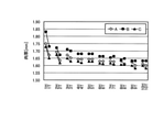
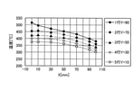
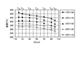
図3及び図4に広幅チャンネル形状形材のダイス2とその温度測定点(P1~P4)を示す。図5にビレット3本連続押出の各測定点の温度履歴の測定結果とFEM解析結果を示す。図5に示すように、押出中、塑性加工の発熱により、ダイス2のベアリング付近部のP3とP4の温度は高くなる。一方、ダイスタックへの伝熱などにより、ダイス2の外周のP1とP2の温度は低くなる。押出先端から押出後端にかけて、ベアリング付近部と外周部の温度差が広がっている。さらに、押出ビレット本数が増えるにつれて、その温度差が大きくなる。
3 and 4 show the
なお、図4は、図3に示す温度測定点P1,P3に対する温度センサの進入方法を説明するためのダイス2の概略断面図である。また、図4におけるi1は、8[mm]である。また、図4におけるi2は、10[mm]である。図4では、温度測定点P1,P3の温度を測定するため、ダイス2に穴H1,H2を設けて温度センサを進入させている。図示しないが、温度測定点P2,P4の温度測定の仕組みも温度測定点P1,P3と同様である。また、第1温度情報取得部61を用いた第1ポイントFP1の温度測定及び第2温度情報取得部62を用いた第2ポイントFP2の温度測定においても、温度測定点P1,P3の温度測定のためにダイス2に穴をあけているのと同様、ダイス2及びビレット3の少なくとも一方に穴をあけて温度センサを進入させる。
Note that FIG. 4 is a schematic cross-sectional view of the
図6にビレット10本連続押出における押出先端材と後端材のA,B,C部の肉厚測定値を示す。各押出ビレットの先端材から後端材にかけて、肉厚が薄くなる傾向にある。ビレット間においても、押出本数が増えるにつれて、肉厚が薄くなっていく。このように、押出先後端、ビレット間の肉厚変動は、負荷とダイス2内の温度変化によるものと考えられる。
FIG. 6 shows the measured values of the wall thicknesses of the A, B, and C portions of the extruded tip material and the rear end material in continuous extrusion of 10 billets. The wall thickness tends to decrease from the tip material to the rear end material of each extruded billet. Even between the billets, the wall thickness becomes thinner as the number of extrusions increases. As described above, the fluctuation in the wall thickness between the rear end of the extrusion destination and the billet is considered to be due to the load and the temperature change in the
(3.フーリエ理論式と差分法の計算)
前述のように、押出加工中に、時間とともに変化するダイス2の温度は、ダイス2の開口に影響を及ぼし、形材肉厚変動の原因となる。定量的にダイス2内部の温度分布と温度変化を検討するため、ここでは、フーリエ理論式と差分法による計算を試みた。
(3. Fourier formula and difference method calculation)
As described above, the temperature of the
図7に2次元の熱伝導の模式図を示す。時間dtの間に、X方向の左から右への熱伝導とY方向の上から下への熱伝導による直方体内部に蓄えられた熱量dQ1の方程式を式(1)のように書ける。

ここで、Tは温度、λは熱伝導率である。 Here, T is the temperature and λ is the thermal conductivity.
なお、温度(T)は、測定又は設定により定められる。熱伝導率(λ)は、例えばダイス2の組成により決定される定数である。また、∂は、偏微分を表す符号である。また、X方向は、行方向に相当する。また、Y方向は、列方向に相当する。
The temperature (T) is determined by measurement or setting. The thermal conductivity (λ) is, for example, a constant determined by the composition of the
一方、時間dtの間に、内部温度変化に必要な熱量dQ2は式(2)となる。ここで、Cは比熱、ρは密度である。

なお、比熱(C)及び密度(ρ)は、例えばダイス2の組成により決定される定数である。
The specific heat (C) and the density (ρ) are constants determined by, for example, the composition of the
式(1)と式(2)から、熱伝導による内部温度変化は式(3)となる。

ここで、a=λ/Cρとすると、式(3)は式(4)となる。

式(4)はフーリエの微分式である。この2重偏微分方程式を解くには、差分法が有効な手法である。 Equation (4) is a differential equation of Fourier. The finite difference method is an effective method for solving this double partial differential equation.
図8に1次元の外部熱と固体の非定常熱伝導の図式解法を示す。ここで、非定常熱伝導の図式解法と差分法計算を説明する。 FIG. 8 shows a schematic solution of one-dimensional external heat and unsteady heat conduction of a solid. Here, the schematic solution method and the finite difference method calculation of unsteady heat conduction will be described.
まず、固体内部の熱伝導計算については、内部のある時間tの温度計算点(T1,T2,T3・・・)を等間隔Δxで分割する。図8に示すように、時間tの温度T2が時間Δxを経過した後、T1,T3との熱伝導により、T2Aとなる。その温度変化の差分法の計算は式(5)となる。
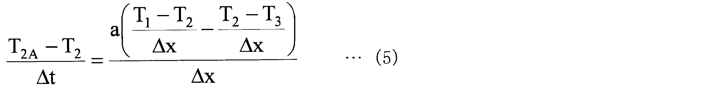
従って、時間t+Δtの温度T2Aと時間tの温度T1,T2,T3の関係は式(6)となる。ここで、M=(Δx)2/aΔt とする。
![]()
![]()
次に、外部熱から固体への熱伝達計算を説明する。外部熱から固体への熱伝達計算を熱伝導計算に直して検討する。この時、熱伝導計算は熱伝達係数と熱伝導率から算出される相当距離を用いて、計算する。 Next, the heat transfer calculation from the external heat to the solid will be described. The calculation of heat transfer from external heat to a solid will be examined by converting it to the calculation of heat conduction. At this time, the heat conduction calculation is calculated using the equivalent distance calculated from the heat transfer coefficient and the heat conductivity.
図8に示すように外部熱の温度をTf、外部熱と固体表面の熱伝達係数をα、固体表面の初期温度をT0、固体の熱伝導率をλとする。 As shown in FIG. 8, the temperature of the external heat is T f , the heat transfer coefficient between the external heat and the solid surface is α, the initial temperature of the solid surface is T 0 , and the thermal conductivity of the solid is λ.
熱伝達により、外部熱から固体表面への熱流束qの計算式は式(7)となる。
![]()
![]()
一方、熱伝導と考えた場合、外部熱から固体表面への熱流束qの計算式は式(8)となる。
![]()
![]()
式(7)と式(8)から、式(9)の等式を書ける。
![]()
![]()
式(9)により、外部熱から固体表面への熱伝達を熱伝導に直した場合、外部熱と固体表面の相当距離dxは、熱伝達係数と熱伝導率から、式(10)で求められる。
![]()
![]()
差分法を利用して外部からの熱伝達を計算するときに、図8に示すように、外部に固体表面から相当距離λ/αの位置に外部雰囲気温度点Tf、固体表面からΔx/2位置にT-1点を設ける必要がある。T-1の値は、固体表面点T0と外部点Tfのx座標の線形関係から計算できる。T-1の値が求めれば、t+Δt時間のT1Aは式(6)のように、t時間のT-1,T1,T2から計算できる。T1Aが決まれば、T1AとT-1の線形関係から、表面T0A(T0のt+Δt時間の温度)が計算できる。 When calculating the heat transfer from the outside using the finite difference method, as shown in FIG. 8, the external atmosphere temperature point T f is located at a considerable distance λ / α from the solid surface to the outside, and Δx / 2 from the solid surface. It is necessary to provide a T -1 point at the position. The value of T -1 can be calculated from the linear relationship between the x-coordinate of the solid surface point T 0 and the external point T f . Once the value of T -1 is obtained, T 1A of t + Δt time can be calculated from T -1 , T 1 , T 2 of t time as in Eq. (6). Once T 1A is determined, the surface T 0A (temperature at t + Δt time of T 0 ) can be calculated from the linear relationship between T 1A and T -1 .
このように、設定された時間ステップで、固体内部の各計算点の温度が計算される。また、各計算点の温度結果を次の時間ステップの伝熱計算の初期温度として定義し、温度変化を計算する。時間ステップの繰り返し計算により、外部熱と固体、固体内部の非定常伝熱解析を行う。繰り返し計算は表計算ソフトウェア・プログラムを利用した演算部71による演算等で実施可能である。 In this way, the temperature of each calculation point inside the solid is calculated in the set time step. In addition, the temperature result at each calculation point is defined as the initial temperature of the heat transfer calculation in the next time step, and the temperature change is calculated. Unsteady heat transfer analysis of external heat, solid, and solid inside is performed by iterative calculation of time steps. The iterative calculation can be performed by a calculation by the calculation unit 71 using a spreadsheet software program or the like.
なお、ダイス2の外部の雰囲気温度(Tf)は、第1温度情報取得部61、第2温度情報取得部62、第3温度情報取得部63、第4温度情報取得部64又は第5温度情報取得部65によって取得される。初期のダイス2の表面の温度(T0)は、予め定められたダイス2の初期温度(例えば、450[℃])である。ダイス2は、押出加工の開始前に初期温度になるよう加熱される。
The ambient temperature (T f ) outside the
(4.押出加工中のダイスの熱伝導計算)
(4.1 ダイスの熱伝導計算)
図9にフーリエ理論式と差分法によるダイス2の熱伝導計算のモデルを示す。押出加工中のダイス2の入熱と放熱は、ダイスチャンバー内のメタル加工熱からの入熱F0、ダイス2のベアリングのメタル摩擦熱からの入熱F1、ダイス逃げ部の空気との界面からの放熱F2、ダイス後部の工具系との接触からの放熱F3、ダイスタックとの接触からの放熱F4と定義する。
(4. Calculation of heat conduction of dies during extrusion)
(4.1 Heat conduction calculation of dice)
FIG. 9 shows a model of heat conduction calculation of the
以下、単にF0と記載した場合、入熱F0をさす。また、単にF1と記載した場合、入熱F1をさす。また、単にF2と記載した場合、放熱F2をさす。また、単にF3と記載した場合、放熱F3をさす。また、単にF4と記載した場合、放熱F4をさす。 Hereinafter, when simply described as F0, it refers to heat input F0. Further, when it is simply described as F1, it means the heat input F1. Further, when simply described as F2, it refers to heat dissipation F2. Further, when simply described as F3, it refers to heat dissipation F3. Further, when simply described as F4, it refers to heat dissipation F4.
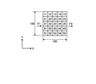
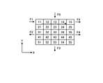
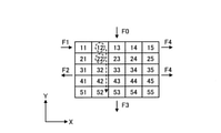
図9では、ダイスの仮想モデルとして、行列方向(X方向×Y方向)に5×5の部分領域が設定された分割モデルを例示している。図9及び後述する図20、図21、図22及び図23等に示すダイスの仮想モデルは、例えば図2に示すダイス2の断面2Vの仮想モデルである。また、各部分領域を区別する目的で、それぞれ異なる番号(11~15,21~25,31~35,41~45,51~55)を付している。この番号の10の位がX方向の位置を示し、1の位がY方向の位置を示す。
FIG. 9 exemplifies a division model in which a 5 × 5 partial region is set in the matrix direction (X direction × Y direction) as a virtual model of the dice. The virtual model of the dice shown in FIG. 9 and FIGS. 20, 21, 22, 23, etc., which will be described later, is, for example, a virtual model having a cross section of 2V of the
図9及び後述する図20、図21、図22及び図23等に示す入熱F0は、Y方向の一端に配置された部分領域に「11」、「12」、「13」、「14」、「15」が付されている5列分の部分領域に対する入熱として機能する。図9に示す放熱F3は、Y方向の一端に配置された部分領域に「51」、「52」、「53」、「54」、「55」が付されている5列分の部分領域からの放熱として機能する。図9に示す入熱F1は、X方向の一端に配置された部分領域に「11」が付されている1行分の部分領域に対する入熱として機能する。図9に示す放熱F2は、X方向の一端に配置された部分領域に「21」、「31」、「41」、「51」が付された1行分の部分領域からの放熱として機能する。図9に示す放熱F4は、X方向の他端に配置された部分領域に「15」、「25」、「35」、「45」、「55」が付されている1行分の部分領域からの放熱として機能する。 The heat input F0 shown in FIG. 9 and FIGS. 20, 21, 22, 23, etc., which will be described later, has "11", "12", "13", "14" in a partial region arranged at one end in the Y direction. , "15" functions as heat input to the partial areas of 5 columns. The heat dissipation F3 shown in FIG. 9 is from a partial region for five rows in which "51", "52", "53", "54", and "55" are added to the partial region arranged at one end in the Y direction. Functions as heat dissipation. The heat input F1 shown in FIG. 9 functions as heat input to a partial region for one row in which "11" is attached to the partial region arranged at one end in the X direction. The heat dissipation F2 shown in FIG. 9 functions as heat dissipation from one row of partial regions having "21", "31", "41", and "51" added to the partial regions arranged at one end in the X direction. .. The heat dissipation F4 shown in FIG. 9 is a partial region for one line in which "15", "25", "35", "45", and "55" are added to the partial region arranged at the other end in the X direction. Functions as heat dissipation from.
また、入熱F0は、第1箇所におけるダイス2への入熱に相当する。また、入熱F1は、第2箇所におけるダイス2への入熱に相当する。また、放熱F2は、第3箇所におけるダイス2からの放熱に相当する。また、放熱F3は、第4箇所におけるダイス2からの放熱に相当する。また、放熱F4は、第5箇所におけるダイス2からの放熱に相当する。
Further, the heat input F0 corresponds to the heat input to the
例示する解析モデルは5行×5列に分けられて、計25要素である。 The example analysis model is divided into 5 rows × 5 columns, and has a total of 25 elements.
(4.2 1次元の左右方向の熱伝導計算)
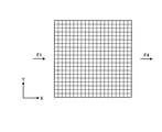
まず、図10に示す1次元の場合、左からのF1の入熱と右へのF4の放熱の計算を検討する。モデルの形状は正方形の100×100mmである。
(4.2 One-dimensional horizontal heat conduction calculation)
First, in the case of one dimension shown in FIG. 10, the calculation of the heat input of F1 from the left and the heat dissipation of F4 to the right will be examined. The shape of the model is a square 100 x 100 mm.
ダイス2の初期温度は450℃、熱伝導率は30W/(m・℃)、比熱は460J/(kg・℃)、密度は7800kg/m3である。モデルは平面モデルである。
The initial temperature of the
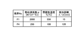
F1とF4の境界条件である熱伝達係数と雰囲気温度および熱伝達を熱伝導に直した場合の相当距離を図11に示す。計算時間は300sである。差分法の計算時間間隔を6sとし、計算ステップは50である。 FIG. 11 shows the heat transfer coefficient, which is the boundary condition between F1 and F4, the ambient temperature, and the equivalent distance when the heat transfer is converted to heat conduction. The calculation time is 300 s. The calculation time interval of the difference method is 6 s, and the calculation step is 50.
なお、300sは、300秒(s:second)をさす。6sは、6秒(s)をさす。 In addition, 300s means 300 seconds (s: second). 6s refers to 6 seconds (s).
差分法の計算精度を検討するため、非定常伝熱のFEM解析を行った。非定常伝熱のFEM解析は汎用FEM解析ソフトAnsys18.0(登録商標)を用いた。図12にFEM解析モデルを示す。要素は分割サイズが5mmで、計400個である。 In order to examine the calculation accuracy of the difference method, FEM analysis of unsteady heat transfer was performed. For the FEM analysis of unsteady heat transfer, general-purpose FEM analysis software Ansys 18.0 (registered trademark) was used. FIG. 12 shows an FEM analysis model. The elements have a division size of 5 mm, and there are a total of 400 elements.
図13に300s経過後のFEM解析結果の温度分布図を示す。左から右に向かって、温度が低くなる。図14に300s経過後の差分法計算結果とFEM解析結果の比較を示す。両者は一致していることが分かる。従って、1次元の場合、左右からの2つの熱境界条件の伝熱解析において、差分法の計算精度が高いことが分かる。 FIG. 13 shows a temperature distribution map of the FEM analysis result after 300 s has elapsed. The temperature decreases from left to right. FIG. 14 shows a comparison between the difference method calculation result and the FEM analysis result after the lapse of 300 s. It can be seen that the two are in agreement. Therefore, in the case of one dimension, it can be seen that the calculation accuracy of the difference method is high in the heat transfer analysis of the two thermal boundary conditions from the left and right.
[4.3 2次元の左右、上下方向の熱伝導解析]
図9に示すようにダイス2の熱伝導は左右、上下方向である。ここで、同様に正方形の100×100mmのモデルを用いて、図9の5つの境界条件の伝熱解析を検討する。ベアリング部の長さは20mmとする。
[4.3 Two-dimensional horizontal and vertical heat conduction analysis]
As shown in FIG. 9, the heat conduction of the
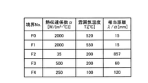
図9の5つの境界条件である熱伝達係数と雰囲気温度、熱伝達を熱伝導に直した場合の相当距離を図15に示す。計算時間は300sである。差分法の計算時間間隔を6sとし、計算ステップは50である。同様に、差分法の計算精度を検討するため、非定常伝熱のFEM解析を行った。 FIG. 15 shows the heat transfer coefficient and the atmospheric temperature, which are the five boundary conditions of FIG. 9, and the equivalent distance when the heat transfer is converted to heat conduction. The calculation time is 300 s. The calculation time interval of the difference method is 6 s, and the calculation step is 50. Similarly, in order to examine the calculation accuracy of the difference method, FEM analysis of unsteady heat transfer was performed.
図15に示す雰囲気温度(Tf)は、温度情報取得装置60により取得される温度である。境界No.「F0」の雰囲気温度(Tf=520[℃])は、第1温度情報取得部61により取得される。境界No.「F1」の雰囲気温度(Tf=550[℃])は、第2温度情報取得部62により取得される。境界No.「F2」の雰囲気温度(Tf=200[℃])は、第3温度情報取得部63により取得される。境界No.「F3」の雰囲気温度(Tf=200[℃])は、第4温度情報取得部64により取得される。境界No.「F4」の雰囲気温度(Tf=100[℃])は、第5温度情報取得部65により取得される。すなわち、実施形態における入熱F0は、第1箇所で検知された温度により生じるダイス2に対する熱伝導である。また、入熱F1は、第2箇所で検知された温度により生じるダイス2に対する熱伝導である。また、放熱F2は、第3箇所で検知された温度により生じるダイス2に対する熱伝導である。また、放熱F3は、第4箇所で検知された温度により生じるダイス2に対する熱伝導である。また、放熱F4は、第5箇所で検知された温度により生じるダイス2に対する熱伝導である。
The atmospheric temperature (T f ) shown in FIG. 15 is a temperature acquired by the temperature
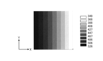
図16に300s経過後のFEM解析結果の温度分布図を示す。図17にFEM解析結果の各行要素のX方向の温度分布を示す。チャンバー内のメタルのF0とベアリング部のF1からの入熱により、ベアリング付近の温度が高くなる。一方、ダイス2外周のF4、逃げ部のF2とバックダイ部のF3の放熱により、ダイス2の内部から外部へ向かって、ダイス2の上面から下面に向かって、温度が低下する。
FIG. 16 shows a temperature distribution map of the FEM analysis result after 300 s has elapsed. FIG. 17 shows the temperature distribution in the X direction of each row element of the FEM analysis result. The temperature near the bearing rises due to the heat input from the metal F0 in the chamber and the bearing F1. On the other hand, due to heat dissipation from F4 on the outer periphery of the
図18に300s経過後の差分法による各行要素のX方向の温度分布の結果を示す。2次元の差分法による各時間ステップの温度計算値は、X方向とY方向の温度計算結果の重ね合わせの値である。 FIG. 18 shows the result of the temperature distribution in the X direction of each row element by the difference method after the lapse of 300 s. The temperature calculation value of each time step by the two-dimensional difference method is a superposition value of the temperature calculation results in the X direction and the Y direction.
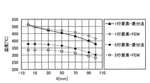
図18の差分法による各行要素の温度計算結果と図17のFEM解析結果を比較すると、両者に差があることが分かる。図19に1行要素と5行要素の差分法計算結果とFEM解析結果の比較を示す。図19から、1行の右側要素の差分法計算結果はFEM解析結果より約36℃低い。一方、5行の右側要素の差分法計算結果はFEM解析結果より全体的に約25℃高い。このように、2次元の場合、単純にX,Y方向の温度計算結果を重ね合わせただけでは、精度が良くないことが分かる。 Comparing the temperature calculation result of each row element by the difference method of FIG. 18 and the FEM analysis result of FIG. 17, it can be seen that there is a difference between the two. FIG. 19 shows a comparison between the difference method calculation result of the 1-line element and the 5-line element and the FEM analysis result. From FIG. 19, the difference method calculation result of the right element in one row is about 36 ° C. lower than the FEM analysis result. On the other hand, the difference method calculation result of the right element of the 5th row is about 25 ° C. higher than the FEM analysis result as a whole. As described above, in the case of two dimensions, it can be seen that the accuracy is not good simply by superimposing the temperature calculation results in the X and Y directions.
前述の差分法計算結果とFEM解析結果の不一致の原因は、計算の初期温度の設定によるものと考えられ、ここで、差分法の計算方法を再考案した。本実施形態の方法は、この再考案された差分法の計算方法による。 The cause of the discrepancy between the above-mentioned difference method calculation result and the FEM analysis result is considered to be due to the setting of the initial temperature of the calculation, and here, the calculation method of the difference method was redesigned. The method of this embodiment is based on the redesigned method of calculating the difference method.
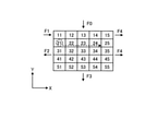
図20から図23に考案した左右、上下の伝熱の計算方法を示す。時間ステップのダイス温度を計算する際、まず、第1ステップは、図20に示すように1行目の要素11と要素15の間に境界条件F1とF4による熱伝導を計算する。次に、第2ステップは、図21の1列目の要素11と要素51の間に境界条件F0とF3による熱伝導を計算する。その際、要素11の初期温度値を第1ステップでの計算後の温度値とする。その後、図22の第3ステップの2行目要素の熱伝導を計算する際、要素21の初期温度値を第2ステップでの1列目計算後の温度値とする。その後、図23の第4ステップの2列目要素の熱伝導を計算する際、要素12と22の初期温度値をそれぞれ第1ステップと第3ステップでの計算後の温度値とする。同じように、3行~5行要素、3列~5列要素の熱伝導を計算する際は、上記の方法で、前の行と列で計算した値を初期温度と定義し、計算する。この計算方法とすれば、X,Y方向の熱伝導の温度変化の影響が考慮され、計算精度の向上につながると考えられる。
20 to 23 show the left-right and upper-bottom heat transfer calculation methods devised. When calculating the die temperature of the time step, the first step first calculates the heat conduction by the boundary conditions F1 and F4 between the
なお、「1行目の要素11と要素15の間に境界条件F1とF4による熱伝導」とは、「ダイスのベアリングのメタル摩擦熱からの入熱F1と、ダイスタックとの接触からの放熱F4との影響によって、ダイスの仮想モデルに設定された1行目の部分領域(要素11、要素12、要素13、要素14、要素15)に生じる熱伝導」をさす。また、「1列目の要素11と要素51の間に境界条件F0とF3による熱伝導」とは、「ダイスチャンバー内のメタル加工熱からの入熱F0と、ダイス後部の工具系との接触からの放熱F3との影響によって、ダイスの仮想モデルに設定された1列目の部分領域(要素11、要素21、要素31、要素41、要素51)に生じる熱伝導」をさす。
In addition, "heat conduction by the boundary conditions F1 and F4 between the
例えば、図15に示す相当距離(λ/α[mm])を図8に示す「λ/α」にあてはめる。図15に示す雰囲気温度(Tf[℃])を図8に示す「Tf」にあてはめる。なお、熱伝達係数α[(W/m2・℃)]は、相当距離(λ/α[mm])を導出するために用いられている。熱伝達係数α[(W/m2・℃)]及び相当距離(λ/α[mm])の少なくとも一方は、押出装置100の具体的構成、押出装置100が置かれる環境等の条件に応じて導出される既定の値として与えられる。
For example, the equivalent distance (λ / α [mm]) shown in FIG. 15 is applied to “λ / α” shown in FIG. The atmospheric temperature (T f [° C.]) shown in FIG. 15 is applied to “T f ” shown in FIG. The heat transfer coefficient α [(W / m2 · ° C.)] is used to derive a considerable distance (λ / α [mm]). At least one of the heat transfer coefficient α [(W / m2 · ° C.)] and the equivalent distance (λ / α [mm]) depends on the specific configuration of the
なお、ダイスの仮想モデルが正方形の100×100mmのモデルである場合、図8に示すΔxは、20mmである。Δx/2は、10mmである。すなわち、Δxは、仮想モデルのX方向(又はY方向)の寸法の1/5である。 When the virtual model of the dice is a square model of 100 × 100 mm, Δx shown in FIG. 8 is 20 mm. Δx / 2 is 10 mm. That is, Δx is 1/5 of the dimension in the X direction (or Y direction) of the virtual model.
具体例として、図20において「11」、「12」、「13」、「14」、「15」が付されている部分領域がX方向に並ぶ1行分の部分領域における初期温度及び算出される温度について説明する。境界No.「F1」の雰囲気温度Tfが「550」であるため、図8のTfに「550」が代入される。また、図8のT0の初期値は、上述の通り、ダイス2の初期温度(例えば、450[℃])である。従って、ここではT0に「450」が代入される。また、図8の「λ/α」に境界No.「F1」の相当距離λ/αの「15」が代入される。また、ダイスの仮想モデルが正方形の100×100mmのモデルであるので、「Δx/2」に、「10」が代入される。これらの値が代入されたTf,T0,λ/α,Δx/2によって、演算部71は、図15の「F1」に対応するT-1を算出する。このT-1が、「11」、「12」、「13」、「14」、「15」が付されている部分領域がX方向に並ぶ1行分の部分領域における、「11」側からの入熱F1に相当する。 As a specific example, the initial temperature and calculation in the partial region of one row in which the partial regions marked with "11", "12", "13", "14", and "15" are arranged in the X direction in FIG. 20 are calculated. The temperature will be described. Boundary No. Since the atmospheric temperature T f of “F1” is “550”, “550” is substituted for T f in FIG. Further, the initial value of T 0 in FIG. 8 is the initial temperature of the die 2 (for example, 450 [° C.]) as described above. Therefore, here, "450" is substituted for T 0 . In addition, the boundary No. is shown at "λ / α" in FIG. "15" of the equivalent distance λ / α of "F1" is substituted. Further, since the virtual model of the dice is a square model of 100 × 100 mm, “10” is substituted for “Δx / 2”. Based on T f , T 0 , λ / α, and Δx / 2 to which these values are substituted, the arithmetic unit 71 calculates T -1 corresponding to “F1” in FIG. This T -1 is from the "11" side in the partial area of one line in which the partial areas marked with "11", "12", "13", "14", and "15" are arranged in the X direction. Corresponds to the heat input F1 of.
図8のT1,T2,T3はそれぞれ、図20において「11」、「12」、「13」が付されている部分領域の初期温度である。この初期温度は、ダイス2の初期温度である。この具体例では、T1,T2,T3にはそれぞれ「450」が代入される。図示しないが、実際には、「14」、「15」が付されている部分領域の初期温度として、T4,T5が設定されている。この具体例では、T4,T5にも「450」が代入される。
T 1 , T 2 , and T 3 in FIG. 8 are the initial temperatures of the partial regions marked with “11”, “12”, and “13” in FIG. 20, respectively. This initial temperature is the initial temperature of the
さらに、図8では図示しないが、「15」側からの放熱F4に相当するT7が設定される。T7は、上述の入熱F1に相当するT-1の算出と同様の仕組みで算出される。すなわち、境界No.「F4」の雰囲気温度Tfが「100」であるため、図8のTfに「100」が代入される。また、図8のT0の初期値は、上述の通り、ダイス2の初期温度(例えば、450[℃])である。従って、ここではT0に「450」が代入される。また、図8の「λ/α」に境界No.「F4」の相当距離λ/αの「120」が代入される。また、ダイスの仮想モデルが正方形の100×100mmのモデルであるので、「Δx/2」に、「10」が代入される。これらの値が代入されたTf,T0,λ/α,Δx/2によって、演算部71は、図15の「F4」に対応するT-1を算出する。この「F4」に対応するT-1が、T7として扱われる。また、T5とT7との間のT6の初期値は、T0の初期値と同一である。
Further, although not shown in FIG. 8, T 7 corresponding to the
このようにして定められたT-1,T0,T1,T2,T3,T4,T5,T6,T7と、上述の式(6)に基づいて、T-1A,T0A,T1A,T2A,T3A,T4A,T5A,T6A及びT7Aが算出される。なお、実施形態では、図15のTfは一定であるものとする。なお、式(6)でT2Aの算出に用いられる3つの値を(T1,T2,T3)と表すことができるとする。この場合、T1Aの算出に用いられる3つの値は、(T-1,T1,T2)であり、T0を含まない。T0Aは、T1AとT-1の線性関係に基づいて求められる。また、T-1Aは、T-1の算出に用いられるTfとT0Aとを結ぶ線分の傾き(TfとT0Aとの差)と、λ/αとΔx/2との比に基づいて求められる。Tfは、「F1」の雰囲気温度Tfである。 T -1 , T 0 , T 1 , T 2 , T 3 , T 4 , T 5 , T 6 , T 7 and T -1A , based on the above equation (6), thus determined. T 0A , T 1A , T 2A , T 3A , T 4A , T 5A , T 6A and T 7A are calculated. In the embodiment, it is assumed that T f in FIG. 15 is constant. It is assumed that the three values used in the calculation of T2A in the equation (6) can be expressed as (T 1 , T 2 , T 3 ). In this case, the three values used in the calculation of T 1A are (T -1 , T 1 , T 2 ) and do not include T 0 . T 0A is obtained based on the linear relationship between T 1A and T -1 . Further, T -1A is the ratio of the slope of the line segment connecting T f and T 0A (difference between T f and T 0 A) used in the calculation of T -1 and λ / α and Δx / 2. Obtained based on. T f is the atmospheric temperature T f of “F1”.
以上、説明した最初の演算(最初の第1算出工程)で、演算部71は、図20において「11」、「12」、「13」、「14」、「15」が付されている部分領域がX方向に並ぶ1行分の部分領域に対応するT-1A,T0A,T1A,T2A,T3A,T4A,T5A,T6A及びT7Aを算出する。ここで、T1Aが「11」の部分領域のt[s]経過後の温度である。T2Aが「12」の部分領域のt[s]経過後の温度である。T3Aが「13」の部分領域のt[s]経過後の温度である。T4Aが「14」の部分領域のt[s]経過後の温度である。T5Aが「15」の部分領域のt[s]経過後の温度である。 In the first calculation (first first calculation step) described above, the calculation unit 71 is the part where "11", "12", "13", "14", and "15" are attached in FIG. 20. Calculate T -1A , T 0A , T 1A , T 2A , T 3A , T 4A , T 5A , T 6A and T 7A corresponding to the partial area of one row in which the areas are lined up in the X direction. Here, T 1A is the temperature after t [s] elapses in the partial region of “11”. T 2A is the temperature after the elapse of t [s] in the partial region of "12". T 3A is the temperature after t [s] elapses in the partial region of “13”. T 4A is the temperature after t [s] elapses in the partial region of “14”. T 5A is the temperature after t [s] elapses in the partial region of “15”.
次に、演算部71は、図21において「11」、「21」、「31」、「41」、「51」が付されている部分領域がY方向に並ぶ1列分の部分領域に対応するT-1A,T0A,T1A,T2A,T3A,T4A,T5A,T6A及びT7Aを算出するための処理を行う。ここで、「11」側からの入熱は、入熱F0である。従って、上述の説明で代入された境界No.「F1」の雰囲気温度Tf及び境界No.「F1」の相当距離λ/αを境界No.「F0」の雰囲気温度Tf及び境界No.「F0」の相当距離λ/αに置換して値を代入し、これらの値が代入されたTf,T0,λ/α,Δx/2によって、演算部71は、図15の「F0」に対応するT-1を算出する。このT-1が、「11」、「21」、「31」、「41」、「51」が付されている部分領域がY方向に並ぶ1列分の部分領域における、「11」側からの入熱F0に相当する。 Next, the calculation unit 71 corresponds to a partial area for one row in which the partial areas marked with "11", "21", "31", "41", and "51" in FIG. 21 are arranged in the Y direction. T -1A , T 0A , T 1A , T 2A , T 3A , T 4A , T 5A , T 6A and T 7A are performed. Here, the heat input from the "11" side is the heat input F0. Therefore, the boundary No. substituted in the above description. Atmospheric temperature T f of "F1" and boundary No. The boundary No. is the equivalent distance λ / α of “F1”. Atmospheric temperature T f of "F0" and boundary No. Substituting values for the equivalent distance λ / α of “F0” and substituting these values T f , T 0 , λ / α, Δx / 2 causes the arithmetic unit 71 to perform “F0” in FIG. ”, The T -1 corresponding to the above is calculated. This T -1 is from the "11" side in the partial area of one row in which the partial areas with "11", "21", "31", "41", and "51" are arranged in the Y direction. Corresponds to the heat input F0 of.
同様の仕組みで、「51」側からの放熱F3に相当するT6は、上述の説明で代入された境界No.「F4」の雰囲気温度Tf及び境界No.「F4」の相当距離λ/αを境界No.「F3」の雰囲気温度Tf及び境界No.「F3」の相当距離λ/αに置換して値を代入し、これらの値が代入されたTf,T0,λ/α,Δx/2によって、演算部71は、図15の「F0」に対応するT-1を算出する。この「F3」に対応するT-1が、「51」側からの放熱F3に相当するT7として扱われる。 By the same mechanism, T6 corresponding to the heat radiation F3 from the “51” side is the boundary No. 1 substituted in the above description. Atmospheric temperature T f of "F4" and boundary No. The boundary No. is the equivalent distance λ / α of “F4”. Atmospheric temperature T f of "F3" and boundary No. Substituting the equivalent distance λ / α of “F3” and substituting the values, and using T f , T 0 , λ / α, and Δx / 2 to which these values are substituted, the arithmetic unit 71 uses “F0” in FIG. ”, The T -1 corresponding to the above is calculated. The T -1 corresponding to this "F3" is treated as the T 7 corresponding to the heat radiation F3 from the "51" side.
このようにして定まったT-1,T7と、図21において「21」、「31」、「41」、「51」が付されている部分領域がY方向に並ぶ1列分の部分領域の初期値T2,T3,T4,T5と、「最初の第1算出工程」で算出された「11」の温度T1Aとに基づいて、演算部71は、「最初の第1算出工程」の後に行われる「最初の第2算出工程」を行う。具体的には、演算部71は、「最初の第2算出工程」において、T1を「最初の第1算出工程」で算出された「11」の温度T1Aで置換する。すなわち、演算部71は、図8に示すT-1,T7に、入熱F0に相当するT-1、放熱F3に相当するT7を代入する。また、演算部71は、T0,T2,T3,T4,T5に、ダイス2の初期温度を代入する。また、演算部71は、T1に、「最初の第1算出工程」で算出された「11」の温度T1Aを代入する。このようにして定められたT-1,T1,T2,T3,T4,T5,T6と、上述の式(6)に基づいて、T-1A,T0A,T1A,T2A,T3A,T4A,T5A,T6A及びT7Aが算出される。ここで、「11」の温度T1Aが再計算される。すなわち、第1算出工程と第2算出工程で同じ部分領域の値が算出される場合、後に行われた工程の値が採用される。
The T - 1 and T7 determined in this way and the partial areas marked with "21", "31", "41", and "51" in FIG. 21 are the partial areas for one row arranged in the Y direction. Based on the initial values T 2 , T 3 , T 4 , and T 5 of, and the temperature T 1A of "11" calculated in the "first first calculation step", the arithmetic unit 71 performs the "first first calculation step". The "first second calculation step" performed after the "calculation step" is performed. Specifically, the calculation unit 71 replaces T 1 with the temperature T 1A of “11” calculated in the “first first calculation step” in the “first second calculation step”. That is, the arithmetic unit 71 substitutes T -1 corresponding to heat input F0 and T 7 corresponding to heat dissipation F3 to T -1 and T 7 shown in FIG. Further, the arithmetic unit 71 substitutes the initial temperature of the
次に、演算部71は、図22において「21」、「22」、「23」、「24」、「25」が付されている部分領域がX方向に並ぶ1行分の部分領域に対応するT-1A,T0A,T1A,T2A,T3A,T4A,T5A,T6A及びT7Aを算出するための処理を行う。ここで、「12」側からの放熱は、放熱F2である。従って、上述の説明で代入された境界No.「F1」の雰囲気温度Tf及び境界No.「F1」の相当距離λ/αを境界No.「F2」の雰囲気温度Tf及び境界No.「F2」の相当距離λ/αに置換して値を代入し、これらの値が代入されたTf,T0,λ/α,Δx/2によって、演算部71は、図15の「F2」に対応するT-1を算出する。このT-1が、「21」、「22」、「23」、「24」、「25」が付されている部分領域がX方向に並ぶ1行分の部分領域における、「21」側からの放熱F2に相当する。なお、放熱F4に相当するT7は、既に算出済みである最初の演算(最初の第1算出処理)におけるT7と同一である。
Next, the calculation unit 71 corresponds to a partial area for one line in which the partial areas marked with "21", "22", "23", "24", and "25" in FIG. 22 are arranged in the X direction. T -1A , T 0A , T 1A , T 2A , T 3A , T 4A , T 5A , T 6A and T 7A are performed. Here, the heat dissipation from the "12" side is the heat dissipation F2. Therefore, the boundary No. substituted in the above description. Atmospheric temperature T f of "F1" and boundary No. The boundary No. is the equivalent distance λ / α of “F1”. Atmospheric temperature T f of "F2" and boundary No. By substituting the equivalent distance λ / α of “F2” and substituting the values, and using T f , T 0 , λ / α, and Δx / 2 to which these values are substituted, the arithmetic unit 71 uses “F2” in FIG. ”, The T -1 corresponding to the above is calculated. This T -1 is from the "21" side in the partial area of one line in which the partial areas marked with "21", "22", "23", "24", and "25" are arranged in the X direction. Corresponds to the heat dissipation F2 of. The T 7 corresponding to the
このようにして定まったT-1,T7と、図22において「22」、「23」、「24」、「25」が付されている部分領域がx方向に並ぶ1行分の部分領域の初期値T2,T3,T4,T5と、「最初の第2算出工程」で算出された「21」の温度T2Aとに基づいて、演算部71は、「最初の第2算出工程」の後に行われる「2回目の第1算出工程」を行う。具体的には、演算部71は、「2回目の第1算出工程」において、T1を「最初の第2算出工程」で算出された「21」の温度T2Aで置換する。すなわち、演算部71は、図8に示すT-1,T7に、放熱F2に相当するT-1、放熱F4に相当するT7を代入する。また、演算部71は、T0,T2,T3,T4,T5に、ダイス2の初期温度を代入する。また、演算部71は、T1に、「最初の第2算出工程」で算出された「21」の温度T2Aを代入する。このようにして定められたT-1,T0,T1,T2,T3,T4,T5,T6,T7と、上述の式(6)に基づいて、T-1A,T0A,T2A,T3A,T4A,T5A,T6A及びT7Aが算出される。
The T - 1 and T7 determined in this way and the partial areas marked with "22", "23", "24", and "25" in FIG. 22 are the partial areas for one line arranged in the x direction. Based on the initial values T 2 , T 3 , T 4 , T 5 of, and the temperature T 2A of "21" calculated in the "first second calculation step", the arithmetic unit 71 performs the "first second calculation step". The "second first calculation step" performed after the "calculation step" is performed. Specifically, the calculation unit 71 replaces T 1 with the temperature T 2A of “21” calculated in the “first second calculation step” in the “second first calculation step”. That is, the arithmetic unit 71 substitutes T -1 corresponding to the heat radiation F 2 and T 7 corresponding to the heat radiation F 4 into T -1 and T 7 shown in FIG. Further, the arithmetic unit 71 substitutes the initial temperature of the
次に、演算部71は、図23において「12」、「22」、「32」、「42」、「52」が付されている部分領域がY方向に並ぶ1列分の部分領域に対応するT-1A,T1A,T2A,T3A,T4A,T5A,T6A及びT0Aを算出するための処理を行う。ここで、「12」側からの入熱は、既に算出済みの入熱F0である。また、「52」側からの放熱は、既に算出済みの放熱F3である。 Next, the calculation unit 71 corresponds to a partial area for one row in which the partial areas marked with "12", "22", "32", "42", and "52" in FIG. 23 are arranged in the Y direction. T -1A , T 1A , T 2A , T 3A , T 4A , T 5A , T 6A and T 0A are processed. Here, the heat input from the "12" side is the heat input F0 that has already been calculated. Further, the heat radiation from the "52" side is the heat radiation F3 that has already been calculated.
このようにして定まったT-1,T6と、図23において「32」、「42」、「52」が付されている部分領域がY方向に並ぶ1列分の部分領域の初期値T3,T4,T5と、「最初の第1算出工程」で算出された「12」の温度T2A及び「2回目の第1算出工程」で算出された「22」の温度T2Aとに基づいて、演算部71は、「2回目の第2算出工程」を行う。すなわち、演算部71は、図8に示すT-1,T7に、入熱F3に相当するT-1、放熱F3に相当するT6を代入する。また、演算部71は、T3,T4,T5に、ダイス2の初期温度を代入する。また、演算部71は、T0,T1に、「最初の第1算出工程」で算出された「12」の温度T2Aを代入する。また、演算部71は、T2に、「2回目の第1算出工程」で算出された「22」の温度T2Aを代入する。このようにして定められたT-1,T0,T1,T2,T3,T4,T5,T6,T7と、上述の式(6)に基づいて、T-1A,T0A,T2A,T3A,T4A,T5A,T6A及びT7Aが算出される。
The initial value T of the partial area for one row in which the T - 1 and T6 determined in this way and the partial areas marked with "32", "42", and "52" in FIG. 23 are arranged in the Y direction. 3 , T 4 , T 5 , and the temperature T 2A of "12" calculated in the "first first calculation step" and the temperature T 2A of "22" calculated in the "second first calculation step". Based on the above, the calculation unit 71 performs the “second second calculation step”. That is, the arithmetic unit 71 substitutes T -1 corresponding to the
以後、図示しないが、5番目の演算(3回目の第1算出工程)では、それ以前の第2算出工程で算出済みの「31」、「32」が付されている部分領域の温度T3A,T3Aを初期値T1,T2に代入する。6番目の演算(3回目の第2算出工程)では、それ以前の第1算出工程で算出済みの「13」、「23」、「33」が付されている部分領域の温度T3A,T3A,T3Aを初期値T1,T2,T3に代入する。7番目の演算(4回目の第1算出工程)では、それ以前の第2算出工程で算出済みの「41」、「42」、「43」が付されている部分領域の温度T4A,T4A,T4Aを初期値T1,T2,T3に代入する。8番目の演算(4回目の第2算出工程)では、それ以前の第1算出工程で算出済みの「14」、「24」、「34」、「44」が付されている部分領域の温度T4A,T4A,T4A,T4Aを初期値T1,T2,T3,T4に代入する。9番目の演算(5回目の第1算出工程)では、それ以前の第2算出工程で算出済みの「51」、「52」、「53」、「54」が付されている部分領域の温度T5A,T5A,T5A,T5Aを初期値T1,T2,T3,T4に代入する。10番目の演算(5回目の第2算出工程)では、それ以前の第1算出工程で算出済みの「15」、「25」、「35」、「45」、「55」が付されている部分領域の温度T5A,T5A,T5A,T5A,T5Aを初期値T1,T2,T3,T4,T5に代入する。 Hereinafter, although not shown, in the fifth calculation (third first calculation step), the temperature T 3A of the partial region with "31" and "32" calculated in the second calculation step before that. , T 3A are substituted into the initial values T 1 and T 2 . In the sixth calculation (third second calculation step), the temperatures T 3A , T of the partial regions with "13", "23", and "33" calculated in the first calculation step before that. Substitute 3A and T 3A into the initial values T 1 , T 2 and T 3 . In the seventh calculation (fourth first calculation step), the temperatures T 4A , T of the partial regions with "41", "42", "43" calculated in the second calculation step before that. Substitute 4A and T 4A into the initial values T 1 , T 2 and T 3 . In the eighth calculation (fourth second calculation step), the temperature of the partial region marked with "14", "24", "34", "44" calculated in the first calculation step before that. Substitute T 4A , T 4A , T 4A , and T 4A into the initial values T 1 , T 2 , T 3 , and T 4 . In the ninth calculation (fifth first calculation step), the temperature of the partial region marked with "51", "52", "53", "54" calculated in the second calculation step before that. Substitute T 5A , T 5A , T 5A , and T 5A into the initial values T 1 , T 2 , T 3 , and T 4 . In the tenth calculation (fifth second calculation step), "15", "25", "35", "45", and "55" calculated in the previous first calculation step are added. Substitute the temperature T 5A , T 5A , T 5A , T 5A , T 5A of the partial region into the initial values T 1 , T 2 , T 3 , T 4 , T 5 .
以上、特筆した「それ以前の算出工程の値を参照した置換」を除いた各部分領域の初期値は、ダイス2の初期温度である。また、2回目以降の第1算出工程における一端側からの放熱(T-1)と他端側からの放熱(T7)は、既に算出済みの放熱F2と放熱F4である。また、第2算出工程における一端側からの入熱(T-1)と他端側からの放熱(T7)は、既に算出済みの入熱F1と放熱F3である。
As described above, the initial value of each partial region excluding the specially mentioned "replacement with reference to the value of the calculation step before that" is the initial temperature of the
このように、演算部71は、ダイス2の内周側における第2箇所からの入熱量F1及びダイス2の内周側における第3箇所への放熱量F2と、ダイス2の外周側から第5箇所への放熱量F4と、予め定められた各部分領域の初期温度とに基づいて、1行分に含まれる各部分領域の温度を算出する第1算出工程と、ダイス2の一端側における第1箇所からの入熱量F0と、ダイス2の他端側から第4箇所への放熱量F3と、予め定められた各部分領域の初期温度とに基づいて、1列分に含まれる各部分領域の温度を算出する第2算出工程と、を行う。また、第1算出工程と第2算出工程は、tを同一の値として、それぞれ複数回行われる。また、第1算出工程と第2算出工程は交互に行われる。また、2回目以降の第1算出工程では、温度を算出する1行分の各部分領域の温度のうち、それ以前の第2算出工程で算出された部分領域の温度を当該部分領域の初期温度とする。また、2回目以降の第2算出工程では、温度を算出する1列分の各部分領域の温度のうち、それ以前の第1算出工程で算出された部分領域の温度を当該部分領域の初期温度とする。
As described above, the calculation unit 71 has the heat input amount F1 from the second place on the inner peripheral side of the
また、1回目の第1算出工程と1回目の第2算出工程のうち、後に行われる工程では、先に行われる工程で算出された部分領域の温度を当該部分領域の初期温度とする。なお、上述の説明では、第1算出工程が先に行われているが、第2算出工程を先に行ってもよい、その場合、最初(1回目の第2算出工程)で算出された「11」の部分領域の温度T1Aを、2番目(1回目の第1算出工程)の「11」の部分領域の初期値T1に代入する。 Further, in the later step of the first first calculation step and the first second calculation step, the temperature of the partial region calculated in the earlier step is set as the initial temperature of the partial region. In the above description, the first calculation step is performed first, but the second calculation step may be performed first. In that case, the first (first second calculation step) is calculated as ". The temperature T 1A of the partial region of "11" is substituted into the initial value T 1 of the partial region of "11" of the second (first first calculation step).
実施形態では、上述のように、計算時間は300sである。また、差分法の計算時間間隔を6sとし、計算ステップは50である。具体的には、初期温度450[℃]であるタイミングを開始時点(0s)とする。このタイミングにおける全ての部分領域のダイス2の温度は、初期温度(450[℃])である。演算部71は、t=6を設定し、上述の式(6)に基づいて、上述のように第1算出工程と第2算出工程を繰り返して開始時点から6s経過後の各部分領域の温度を算出する。
In the embodiment, as described above, the calculation time is 300 s. Further, the calculation time interval of the difference method is 6 s, and the calculation step is 50. Specifically, the timing at which the initial temperature is 450 [° C.] is set as the start time point (0s). The temperature of the
次に、演算部71は、t=6を設定して開始時点(0s)の初期温度に基づいて算出された各部分領域の温度を初期温度(T1,T2,…)とし、改めてt=6を設定し、上述の式(6)に基づいて、上述のように第1算出工程と第2算出工程を繰り返す。これによって、開始時点から12s経過後の各部分領域の温度が算出される。以下、算出された温度を初期温度とした処理を計算ステップの回数だけ繰り返すことで、計算時間(300s)後の各部分領域の温度及びそれまでの6秒間隔での各部分領域の温度が算出される。
Next, the arithmetic unit 71 sets t = 6 and sets the temperature of each partial region calculated based on the initial temperature at the start time (0s) as the initial temperature (T 1 , T 2 , ...), And t again. = 6 is set, and the first calculation step and the second calculation step are repeated as described above based on the above formula (6). As a result, the temperature of each
このように、所定時間が経過することが想定された所定時間前後の異なる2タイミングの各々における温度分布算出工程において、後のタイミングにおける各部分領域の初期温度は、前のタイミングの温度分布算出工程で算出された各部分領域の温度である。 In this way, in the temperature distribution calculation step at each of the two different timings before and after the predetermined time, which is assumed that the predetermined time elapses, the initial temperature of each partial region at the later timing is the temperature distribution calculation step at the previous timing. It is the temperature of each partial region calculated in.
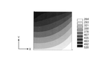
図24に考案した差分法計算方法による各行要素のX方向の温度分布を示す。図24の差分法の温度計算結果と図17のFEM解析結果を比較すると、全体的に一致していることが分かる。 FIG. 24 shows the temperature distribution in the X direction of each row element by the difference method calculation method devised. Comparing the temperature calculation results of the difference method of FIG. 24 with the FEM analysis results of FIG. 17, it can be seen that they are in agreement as a whole.
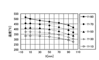
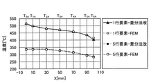
図25に考案した差分法の1行要素と5行要素の計算結果とFEM解析結果の比較を示す。両者は一致する。このように、2次元の熱伝導解析においても、2方向からの熱伝導の影響が考慮されることによって、計算精度が高い差分法計算方法が得られた。 FIG. 25 shows a comparison between the calculation results and the FEM analysis results of the 1-line element and the 5-line element of the difference method devised. Both match. As described above, in the two-dimensional heat conduction analysis, the influence of heat conduction from two directions is taken into consideration, so that a finite difference calculation method with high calculation accuracy can be obtained.
なお、図24及び図25では、実施形態によるダイス2の温度計算方法によって導出された300s後のダイス2の温度分布と、FEM解析によって導出された300s後のダイス2の温度分布とを比較している。図24及び図25では、300s後の各部分領域の温度を、上述の第1算出工程及び第2算出工程で算出されるT0A,T1A,T2A,T3A,T4A,T5A,T6Aで表している。
In FIGS. 24 and 25, the temperature distribution of the
また、図24における「1行Y=90」は、図9等において「11」、「12」、「13」、「14」、「15」が付されている部分領域がX方向に並ぶ1行分の部分領域に対応する。また、図24における「2行Y=70」は、図9等において「21」、「22」、「23」、「24」、「25」が付されている部分領域がX方向に並ぶ1行分の部分領域に対応する。また、図24における「3行Y=50」は、図9等において「31」、「32」、「33」、「34」、「35」が付されている部分領域がX方向に並ぶ1行分の部分領域に対応する。また、図24における「4行Y=30」は、図9等において「41」、「42」、「43」、「44」、「45」が付されている部分領域がX方向に並ぶ1行分の部分領域に対応する。また、図24における「5行Y=10」は、図9等において「51」、「52」、「53」、「54」、「55」が付されている部分領域がX方向に並ぶ1行分の部分領域に対応する。 Further, in FIG. 24, “1 row Y = 90” is a partial region in which “11”, “12”, “13”, “14”, and “15” are attached in the X direction in FIG. 9 and the like. Corresponds to a partial area of a line. Further, in FIG. 24, “2 rows Y = 70” means that the partial regions marked with “21”, “22”, “23”, “24”, and “25” in FIG. 9 and the like are arranged in the X direction1. Corresponds to a partial area of a line. Further, in FIG. 24, “3 rows Y = 50” means that the partial regions marked with “31”, “32”, “33”, “34”, and “35” in FIG. 9 and the like are arranged in the X direction1. Corresponds to a partial area of a line. Further, in FIG. 24, “4 rows Y = 30” means that the partial regions marked with “41”, “42”, “43”, “44”, and “45” in FIG. 9 and the like are arranged in the X direction1. Corresponds to a partial area of a line. Further, in FIG. 24, “5 rows Y = 10” means that the partial regions marked with “51”, “52”, “53”, “54”, and “55” in FIG. 9 and the like are arranged in the X direction1. Corresponds to a partial area of a line.
また、図25における「1行要素」は、図9等において「11」、「12」、「13」、「14」、「15」が付されている部分領域がX方向に並ぶ1行分の部分領域に対応する。また、図25における「5行要素」は、図9等において「51」、「52」、「53」、「54」、「55」が付されている部分領域がX方向に並ぶ1行分の部分領域に対応する。また、図25における「差分法改」は、実施形態によるダイス2の温度計算方法であることを示す。また、図25における「FEM」は、FEM解析による演算結果であることを示す。
Further, the "one-line element" in FIG. 25 is one line in which the partial areas with "11", "12", "13", "14", and "15" are arranged in the X direction in FIG. 9 and the like. Corresponds to a partial area of. Further, the "5-line element" in FIG. 25 is one line in which the partial areas marked with "51", "52", "53", "54", and "55" are arranged in the X direction in FIG. 9 and the like. Corresponds to a partial area of. Further, the "difference method modification" in FIG. 25 indicates that the temperature calculation method for the
図26に差分法計算による押出加工中のダイス2のベアリング付近要素E11と外周側要素E15の経過時間と温度履歴の関係を示す。今回考案した計算方法を用いることにより、押出先後端におけるダイス2の内部と外部の温度差を定量的に検討できる。
FIG. 26 shows the relationship between the elapsed time and the temperature history of the bearing vicinity element E11 and the outer peripheral side element E15 of the
なお、図26におけるE11は、図9等において「11」が付されている部分領域に対応する。また、図26におけるE15は、図9等において「15」が付されている部分領域に対応する。図26は、差分法の計算時間間隔を6sとし、計算ステップを50とした0s~300sまでの各タイミングの部分領域の温度を結ぶ線を描くグラフである。 Note that E11 in FIG. 26 corresponds to the partial region marked with "11" in FIG. 9 and the like. Further, E15 in FIG. 26 corresponds to the partial region marked with “15” in FIG. 9 and the like. FIG. 26 is a graph drawing a line connecting the temperatures of the partial regions of each timing from 0s to 300s when the calculation time interval of the difference method is 6s and the calculation step is 50.
[作用効果]
以上、本実施形態によれば、FEM解析により近似する各部分領域の温度を算出することができる。すなわち、FEM解析と同等の高精度な演算を、FEM解析を実施可能な環境によらず得ることができる。このように、実施形態によれば、より容易にダイス2の温度分布をシミュレートすることができ、しかも、FEM解析と同等の高精度な演算結果を得られる。
[Action effect]
As described above, according to the present embodiment, the temperature of each partial region approximated by FEM analysis can be calculated. That is, it is possible to obtain a high-precision operation equivalent to the FEM analysis regardless of the environment in which the FEM analysis can be performed. As described above, according to the embodiment, the temperature distribution of the
[その他]
なお、金属はアルミニウムに限られない。また、合金はアルミニウムを含む合金に限られない。金属又は合金は、ダイス2を用いた押出加工を適用可能な金属又は合金であればよい。
[others]
The metal is not limited to aluminum. Further, the alloy is not limited to the alloy containing aluminum. The metal or alloy may be any metal or alloy to which extrusion processing using the
上述した「モデルの形状(正方形、100mm×100mm)」、「ベアリング部の長さ(20mm)」、「計算時間(300s)」、「差分法の計算時間間隔(6s)」、「計算ステップ(50)」はあくまで一例であり、これに限られるものでなく、適宜変更可能である。また、解析モデルは25要素に限られない。解析モデルは、行列方向にh×vであればよい。h及びvは、2以上の自然数である。 "Model shape (square, 100 mm x 100 mm)", "bearing length (20 mm)", "calculation time (300s)", "calculation time interval of difference method (6s)", "calculation step (calculation step)" described above. "50)" is merely an example, and is not limited to this, and can be changed as appropriate. Moreover, the analysis model is not limited to 25 elements. The analysis model may be h × v in the matrix direction. h and v are natural numbers of 2 or more.
上述の実施形態における仮想モデルは、ダイス2の断面の平面モデルであるが、ダイス2の軸対称モデルであってもよい。
The virtual model in the above-described embodiment is a planar model of the cross section of the
以上、本願発明の種々の有用な実施例を示し、かつ、説明を施した。本願発明は、上述した種々の実施例や変形例に限定されること無く、この発明の要旨や添付する特許請求の範囲に記載された内容を逸脱しない範囲で種々変形可能であることは言うまでも無い。 As described above, various useful examples of the present invention have been shown and described. It goes without saying that the present invention is not limited to the various examples and modifications described above, and can be variously modified without departing from the contents described in the gist of the present invention and the attached claims. There is no such thing.
1 温度計算システム
2 ダイス
2V 断面
3 ビレット
60 温度情報取得装置
61 第1温度情報取得部
62 第2温度情報取得部
63 第3温度情報取得部
64 第4温度情報取得部
65 第5温度情報取得部
70 情報処理装置
71 演算部
1
Claims (4)
前記ダイスにおける前記押出対象の押出方向を列方向とし、前記押出方向に直交する方向を行方向として、前記押出対象の押出口が配置される前記ダイスの中央部に対する行方向断面の仮想モデルを設定する工程と、
前記仮想モデルにおいて、前記行方向及び前記列方向に複数の部分領域を含む2次元マトリクス状の分割モデルを設定する工程と、
前記ダイスに対して前記押出方向に押し当てられる前記押出対象が存する第1箇所と、前記ダイスから押し出される前記押出対象が存する第2箇所と、前記第2箇所に対して前記押出方向側であって前記ダイスの内側の空間である第3箇所と、前記ダイスの前記押出方向側の端部側の空間である第4箇所と、前記第2箇所及び前記第3箇所の反対側に位置する前記ダイスの外周側の空間である第5箇所と、の温度を取得する工程と、
前記第1箇所及び前記第2箇所における前記ダイスに対する入熱量と、前記第3箇所、前記第4箇所及び前記第5箇所における前記ダイスからの放熱量と、を算出する工程と、
前記分割モデルに含まれる各部分領域の温度を算出する温度分布算出工程と、を含み、
前記温度分布算出工程は、
前記ダイスの内周側における前記第2箇所からの入熱量及び前記ダイスの内周側における前記第3箇所への放熱量と、前記ダイスの外周側から前記第5箇所への放熱量と、予め定められた各部分領域の初期温度とに基づいて、1行分に含まれる各部分領域の温度を算出する第1算出工程と、
前記ダイスの一端側における前記第1箇所からの入熱量と、前記ダイスの他端側から前記第4箇所への放熱量と、予め定められた各部分領域の初期温度とに基づいて、1列分に含まれる各部分領域の温度を算出する第2算出工程と、
を含み、
前記第1算出工程と前記第2算出工程はそれぞれ複数回行われ、
前記第1算出工程と前記第2算出工程は交互に行われ、
2回目以降の前記第1算出工程では、温度を算出する1行分の各部分領域の温度のうち、それ以前の前記第2算出工程で算出された部分領域の温度を当該部分領域の前記初期温度とし、
2回目以降の前記第2算出工程では、温度を算出する1列分の各部分領域の温度のうち、それ以前の前記第1算出工程で算出された部分領域の温度を当該部分領域の前記初期温度とすることを特徴とする、
ダイスの温度計算方法。 A method for calculating the temperature of a die that simulates the temperature distribution of a die used for extrusion of a metal or alloy object to be extruded.
A virtual model of a row-direction cross section with respect to the center of the die in which the extrusion port of the extrusion target is arranged is set with the extrusion direction of the extrusion target in the die as the column direction and the direction orthogonal to the extrusion direction as the row direction. And the process to do
In the virtual model, a step of setting a two-dimensional matrix-like division model including a plurality of partial regions in the row direction and the column direction, and
The first location where the extrusion target is pressed against the die in the extrusion direction, the second location where the extrusion target is extruded from the die, and the extrusion direction side with respect to the second location. The third location, which is the space inside the die, the fourth location, which is the space on the end side of the die on the extrusion direction side, and the second location and the third location opposite to the third location. The process of acquiring the temperature of the fifth location, which is the space on the outer peripheral side of the die, and
A step of calculating the amount of heat input to the dice at the first place and the second place, and the amount of heat radiated from the dice at the third place, the fourth place, and the fifth place.
Including a temperature distribution calculation step of calculating the temperature of each partial region included in the divided model.
The temperature distribution calculation step is
The amount of heat input from the second location on the inner peripheral side of the dice, the amount of heat dissipated to the third location on the inner peripheral side of the dice, and the amount of heat dissipated from the outer peripheral side of the dice to the fifth location in advance. The first calculation step of calculating the temperature of each partial region included in one line based on the initial temperature of each defined partial region, and
One row based on the amount of heat input from the first location on one end side of the dice, the amount of heat released from the other end side of the dice to the fourth location, and the initial temperature of each predetermined partial region. The second calculation step to calculate the temperature of each partial region included in the minute,
Including
The first calculation step and the second calculation step are each performed a plurality of times.
The first calculation step and the second calculation step are alternately performed, and the first calculation step and the second calculation step are performed alternately.
In the first calculation step after the second time, among the temperatures of each partial region for one line for calculating the temperature, the temperature of the partial region calculated in the second calculation step before that is the initial temperature of the partial region. As the temperature
In the second and subsequent calculation steps, the temperature of the partial region calculated in the first calculation step before that of the temperature of each partial region for one row for calculating the temperature is the initial temperature of the partial region. Characterized by temperature,
How to calculate the temperature of the dice.
請求項1に記載のダイスの温度計算方法。 In the step performed later in the first calculation step and the second calculation step of the first time, the temperature of the partial region calculated in the earlier step is set as the initial temperature of the partial region. Characterized by,
The method for calculating the temperature of a die according to claim 1.
請求項1又は2に記載のダイスの温度計算方法。 In the temperature distribution calculation step at each of the two different timings before and after the predetermined time, which is assumed that the predetermined time elapses, the initial temperature of each partial region at the later timing is the temperature distribution calculation step at the previous timing. It is characterized by being the temperature of each partial region calculated in.
The method for calculating the temperature of the dice according to claim 1 or 2.
前記温度情報取得装置は、
前記ダイスに対して前記押出対象の押出方向に押し当てられる前記押出対象が存する第1箇所の温度情報を取得する第1温度情報取得部と、前記ダイスから押し出される前記押出対象が存する第2箇所の温度情報を取得する第2温度情報取得部と、前記第2箇所に対して前記押出方向側であって前記ダイスの内側の空間である第3箇所の温度情報を取得する第3温度情報取得部と、前記ダイスの前記押出方向側の端部側の空間である第4箇所の温度情報を取得する第4温度情報取得部と、前記第2箇所及び前記第3箇所の反対側に位置する前記ダイスの外周側の空間である第5箇所の温度情報を取得する第5温度情報取得部とを有し、
前記情報処理装置は、
前記ダイスにおける前記押出対象の押出方向を列方向とし、前記押出方向に直交する方向を行方向として、前記押出対象の押出口が配置される前記ダイスの中央部に対する行方向断面の仮想モデルを設定し、
前記仮想モデルにおいて、前記行方向及び前記列方向に複数の部分領域を含む2次元マトリクス状の分割モデルを設定し、
前記ダイスの内周側における前記第2箇所からの入熱量及び前記ダイスの内周側における前記第3箇所への放熱量と、前記ダイスの外周側から前記第5箇所への放熱量とを算出し、
前記分割モデルに含まれる各部分領域の温度を算出する演算部を有し、
前記演算部は、
前記第2箇所及び前記第3箇所を含む前記ダイスの内周側からの入熱量及び放熱量と、前記第5箇所を含む前記ダイスの外周側からの放熱量と、予め定められた各部分領域の初期温度とに基づいて、1行分に含まれる各部分領域の温度を算出する第1算出工程と、前記第1箇所を含む前記ダイスの一端側からの入熱量と、前記第4箇所を含む前記ダイスの他端側からの放熱量と、予め定められた各部分領域の初期温度とに基づいて、1列分に含まれる各部分領域の温度を算出する第2算出工程と、をそれぞれ複数回行い、
前記第1算出工程と前記第2算出工程を交互に行い、
2回目以降の前記第1算出工程では、温度を算出する1行分の各部分領域の温度のうち、それ以前の前記第2算出工程で算出された部分領域の温度を当該部分領域の前記初期温度とし、
2回目以降の前記第2算出工程では、温度を算出する1列分の各部分領域の温度のうち、それ以前の前記第1算出工程で算出された部分領域の温度を当該部分領域の前記初期温度とすることを特徴とすることを特徴とする、
ダイスの温度計算システム。 A temperature information acquisition device that acquires temperature information of dies used for extruding a metal or alloy object to be extruded, and an information processing device that simulates the temperature distribution of dies used for extruding a metal or alloy object to be extruded. It is a temperature calculation system for dies equipped with
The temperature information acquisition device is
A first temperature information acquisition unit that acquires temperature information of the first location where the extrusion target exists that is pressed against the die in the extrusion direction of the extrusion target, and a second location where the extrusion target that is extruded from the die exists. The second temperature information acquisition unit that acquires the temperature information of the third location, and the third temperature information acquisition unit that acquires the temperature information of the third location, which is the space inside the die on the extrusion direction side with respect to the second location. It is located on the opposite side of the second and third locations, the fourth temperature information acquisition unit that acquires the temperature information of the fourth location, which is the space on the end side of the die on the extrusion direction side. It has a fifth temperature information acquisition unit that acquires temperature information at a fifth location, which is a space on the outer peripheral side of the die.
The information processing device is
A virtual model of a row-direction cross section with respect to the center of the die in which the extrusion port of the extrusion target is arranged is set with the extrusion direction of the extrusion target in the die as the column direction and the direction orthogonal to the extrusion direction as the row direction. death,
In the virtual model, a two-dimensional matrix-like division model including a plurality of partial regions in the row direction and the column direction is set.
The amount of heat input from the second location on the inner peripheral side of the dice, the amount of heat released to the third location on the inner peripheral side of the dice, and the amount of heat released from the outer peripheral side of the dice to the fifth location are calculated. death,
It has a calculation unit that calculates the temperature of each partial region included in the divided model.
The arithmetic unit
The amount of heat input and heat dissipation from the inner peripheral side of the die including the second place and the third place, the amount of heat radiation from the outer peripheral side of the die including the fifth place, and each predetermined partial region. The first calculation step of calculating the temperature of each partial region included in one row based on the initial temperature of the above, the amount of heat input from one end side of the die including the first location, and the fourth location. A second calculation step of calculating the temperature of each partial region included in one row based on the amount of heat radiated from the other end side of the dice including the die and the initial temperature of each predetermined partial region, respectively. Do it multiple times
The first calculation step and the second calculation step are alternately performed.
In the first calculation step after the second time, among the temperatures of each partial region for one line for calculating the temperature, the temperature of the partial region calculated in the second calculation step before that is the initial temperature of the partial region. As the temperature
In the second and subsequent calculation steps, the temperature of the partial region calculated in the first calculation step before that of the temperature of each partial region for one row for calculating the temperature is the initial temperature of the partial region. Characterized by temperature, characterized by temperature
Dice temperature calculation system.
Priority Applications (1)
| Application Number | Priority Date | Filing Date | Title |
|---|---|---|---|
| JP2018133202A JP6996440B2 (en) | 2018-07-13 | 2018-07-13 | Dice temperature calculation method and dice temperature calculation system |
Applications Claiming Priority (1)
| Application Number | Priority Date | Filing Date | Title |
|---|---|---|---|
| JP2018133202A JP6996440B2 (en) | 2018-07-13 | 2018-07-13 | Dice temperature calculation method and dice temperature calculation system |
Publications (2)
| Publication Number | Publication Date |
|---|---|
| JP2020012654A JP2020012654A (en) | 2020-01-23 |
| JP6996440B2 true JP6996440B2 (en) | 2022-01-17 |
Family
ID=69170840
Family Applications (1)
| Application Number | Title | Priority Date | Filing Date |
|---|---|---|---|
| JP2018133202A Active JP6996440B2 (en) | 2018-07-13 | 2018-07-13 | Dice temperature calculation method and dice temperature calculation system |
Country Status (1)
| Country | Link |
|---|---|
| JP (1) | JP6996440B2 (en) |
Families Citing this family (4)
| Publication number | Priority date | Publication date | Assignee | Title |
|---|---|---|---|---|
| CN114980742A (en) | 2020-01-29 | 2022-08-30 | 日本曹达株式会社 | Agricultural and horticultural compositions |
| CN116508255A (en) | 2020-10-20 | 2023-07-28 | 发那科株式会社 | Temperature estimating device for estimating temperature of motor temperature detector |
| CN116349130B (en) | 2020-10-20 | 2025-12-16 | 发那科株式会社 | Parameter setting device for setting model parameters of motor |
| CN116956378B (en) * | 2023-09-20 | 2024-01-02 | 宁波健信超导科技股份有限公司 | Superconducting magnet heat transfer analysis method, device, equipment and storage medium |
Citations (2)
| Publication number | Priority date | Publication date | Assignee | Title |
|---|---|---|---|---|
| JP2003130829A (en) | 2001-10-22 | 2003-05-08 | Sumitomo Metal Mining Co Ltd | Temperature distribution analysis method for systems containing substances that flow constantly |
| JP2008260044A (en) | 2007-04-12 | 2008-10-30 | Kobe Steel Ltd | Continuous casting method of steel slab for preventing breakout caused by solidification delay |
Family Cites Families (2)
| Publication number | Priority date | Publication date | Assignee | Title |
|---|---|---|---|---|
| JP2540232B2 (en) * | 1990-08-21 | 1996-10-02 | 積水化学工業株式会社 | Integrated mold analysis system |
| JP4174173B2 (en) * | 2000-07-03 | 2008-10-29 | 株式会社神戸製鋼所 | Method and apparatus for extrusion of hollow cross-section metal products |
-
2018
- 2018-07-13 JP JP2018133202A patent/JP6996440B2/en active Active
Patent Citations (2)
| Publication number | Priority date | Publication date | Assignee | Title |
|---|---|---|---|---|
| JP2003130829A (en) | 2001-10-22 | 2003-05-08 | Sumitomo Metal Mining Co Ltd | Temperature distribution analysis method for systems containing substances that flow constantly |
| JP2008260044A (en) | 2007-04-12 | 2008-10-30 | Kobe Steel Ltd | Continuous casting method of steel slab for preventing breakout caused by solidification delay |
Also Published As
| Publication number | Publication date |
|---|---|
| JP2020012654A (en) | 2020-01-23 |
Similar Documents
| Publication | Publication Date | Title |
|---|---|---|
| JP6996440B2 (en) | Dice temperature calculation method and dice temperature calculation system | |
| Chrysochoos | Infrared thermography applied to the analysis of material behavior: a brief overview | |
| US10156506B2 (en) | Residual stress estimation method and residual stress estimation device | |
| US20170011147A1 (en) | Simulation device, simulation program and simulation method for liquid metal | |
| JP2020201146A (en) | Parameter estimating device, parameter estimating method, and program | |
| JP2016197080A (en) | Notch factor estimation method, notch factor estimation system and notch factor estimation device | |
| CN113532654A (en) | Temperature compensation method and device, computer equipment and storage medium | |
| Hanoglu et al. | Simulation of hot shape rolling of steel in continuous rolling mill by local radial basis function collocation method | |
| JP6626665B2 (en) | Method, apparatus, and program for calculating transport coefficient | |
| JP7342708B2 (en) | Dice temperature calculation method and die temperature calculation device | |
| JP6011473B2 (en) | Exhaust system life prediction system | |
| CN118520635A (en) | A method, device, equipment and medium for iteratively solving casting interface heat transfer coefficient | |
| JP3626460B2 (en) | Two-dimensional stress field measurement system and two-dimensional stress field measurement program | |
| JP5737059B2 (en) | Press forming simulation analysis method and apparatus | |
| JP7567885B2 (en) | Physical property prediction method, physical property prediction device, iron slab cooling method, and steel material manufacturing method | |
| JP2013190399A (en) | Dispersibility evaluation method | |
| JP2013202786A (en) | Apparatus, method and program for predicting shrinkage deformation of molding | |
| JP2005043129A (en) | Heat flow analysis method and heat flow analysis system | |
| JP3799419B2 (en) | Non-contact mechanical property measurement system | |
| Holyns’ kyi | Influence of errors of determination of stresses near a crack tip on the accuracy of computation of the coefficients of the Williams series under Mode II loading | |
| JP2014137747A (en) | Structure analyzer, structure analysis method, and structure analysis program | |
| JP2005140509A (en) | Apparatus for calculating equivalent thermal conductivity of composite material and method for calculating equivalent thermal conductivity | |
| Peetala et al. | Prediction of short‐duration transient surface heat flux using various analytical techniques | |
| Thakur et al. | Probabilistic life assessment of gas turbine blades | |
| Ye et al. | Optimal sensor placement for substructural response reconstruction |
Legal Events
| Date | Code | Title | Description |
|---|---|---|---|
| A621 | Written request for application examination |
Free format text: JAPANESE INTERMEDIATE CODE: A621 Effective date: 20210105 |
|
| TRDD | Decision of grant or rejection written | ||
| A977 | Report on retrieval |
Free format text: JAPANESE INTERMEDIATE CODE: A971007 Effective date: 20211110 |
|
| A01 | Written decision to grant a patent or to grant a registration (utility model) |
Free format text: JAPANESE INTERMEDIATE CODE: A01 Effective date: 20211116 |
|
| A61 | First payment of annual fees (during grant procedure) |
Free format text: JAPANESE INTERMEDIATE CODE: A61 Effective date: 20211129 |
|
| R150 | Certificate of patent or registration of utility model |
Ref document number: 6996440 Country of ref document: JP Free format text: JAPANESE INTERMEDIATE CODE: R150 |
|
| R250 | Receipt of annual fees |
Free format text: JAPANESE INTERMEDIATE CODE: R250 |
|
| R250 | Receipt of annual fees |
Free format text: JAPANESE INTERMEDIATE CODE: R250 |