JP6996416B2 - Wire harness and its manufacturing method - Google Patents
Wire harness and its manufacturing method Download PDFInfo
- Publication number
- JP6996416B2 JP6996416B2 JP2018091897A JP2018091897A JP6996416B2 JP 6996416 B2 JP6996416 B2 JP 6996416B2 JP 2018091897 A JP2018091897 A JP 2018091897A JP 2018091897 A JP2018091897 A JP 2018091897A JP 6996416 B2 JP6996416 B2 JP 6996416B2
- Authority
- JP
- Japan
- Prior art keywords
- fixing member
- member mounting
- fixing
- mounting portion
- wire
- Prior art date
- Legal status (The legal status is an assumption and is not a legal conclusion. Google has not performed a legal analysis and makes no representation as to the accuracy of the status listed.)
- Active
Links
Images

Classifications
-
- B—PERFORMING OPERATIONS; TRANSPORTING
- B60—VEHICLES IN GENERAL
- B60R—VEHICLES, VEHICLE FITTINGS, OR VEHICLE PARTS, NOT OTHERWISE PROVIDED FOR
- B60R16/00—Electric or fluid circuits specially adapted for vehicles and not otherwise provided for; Arrangement of elements of electric or fluid circuits specially adapted for vehicles and not otherwise provided for
- B60R16/02—Electric or fluid circuits specially adapted for vehicles and not otherwise provided for; Arrangement of elements of electric or fluid circuits specially adapted for vehicles and not otherwise provided for electric constitutive elements
- B60R16/0207—Wire harnesses
- B60R16/0215—Protecting, fastening and routing means therefor
-
- H—ELECTRICITY
- H01—ELECTRIC ELEMENTS
- H01B—CABLES; CONDUCTORS; INSULATORS; SELECTION OF MATERIALS FOR THEIR CONDUCTIVE, INSULATING OR DIELECTRIC PROPERTIES
- H01B13/00—Apparatus or processes specially adapted for manufacturing conductors or cables
- H01B13/012—Apparatus or processes specially adapted for manufacturing conductors or cables for manufacturing wire harnesses
-
- H—ELECTRICITY
- H01—ELECTRIC ELEMENTS
- H01B—CABLES; CONDUCTORS; INSULATORS; SELECTION OF MATERIALS FOR THEIR CONDUCTIVE, INSULATING OR DIELECTRIC PROPERTIES
- H01B7/00—Insulated conductors or cables characterised by their form
- H01B7/0045—Cable-harnesses
-
- H—ELECTRICITY
- H01—ELECTRIC ELEMENTS
- H01B—CABLES; CONDUCTORS; INSULATORS; SELECTION OF MATERIALS FOR THEIR CONDUCTIVE, INSULATING OR DIELECTRIC PROPERTIES
- H01B7/00—Insulated conductors or cables characterised by their form
- H01B7/17—Protection against damage caused by external factors, e.g. sheaths or armouring
- H01B7/18—Protection against damage caused by wear, mechanical force or pressure; Sheaths; Armouring
- H01B7/1875—Multi-layer sheaths
-
- H—ELECTRICITY
- H01—ELECTRIC ELEMENTS
- H01B—CABLES; CONDUCTORS; INSULATORS; SELECTION OF MATERIALS FOR THEIR CONDUCTIVE, INSULATING OR DIELECTRIC PROPERTIES
- H01B7/00—Insulated conductors or cables characterised by their form
- H01B7/17—Protection against damage caused by external factors, e.g. sheaths or armouring
- H01B7/28—Protection against damage caused by moisture, corrosion, chemical attack or weather
- H01B7/282—Preventing penetration of fluid, e.g. water or humidity, into conductor or cable
- H01B7/2825—Preventing penetration of fluid, e.g. water or humidity, into conductor or cable using a water impermeable sheath
-
- H—ELECTRICITY
- H01—ELECTRIC ELEMENTS
- H01B—CABLES; CONDUCTORS; INSULATORS; SELECTION OF MATERIALS FOR THEIR CONDUCTIVE, INSULATING OR DIELECTRIC PROPERTIES
- H01B7/00—Insulated conductors or cables characterised by their form
- H01B7/40—Insulated conductors or cables characterised by their form with arrangements for facilitating mounting or securing
-
- H—ELECTRICITY
- H01—ELECTRIC ELEMENTS
- H01R—ELECTRICALLY-CONDUCTIVE CONNECTIONS; STRUCTURAL ASSOCIATIONS OF A PLURALITY OF MUTUALLY-INSULATED ELECTRICAL CONNECTING ELEMENTS; COUPLING DEVICES; CURRENT COLLECTORS
- H01R13/00—Details of coupling devices of the kinds covered by groups H01R12/70 or H01R24/00 - H01R33/00
- H01R13/46—Bases; Cases
- H01R13/52—Dustproof, splashproof, drip-proof, waterproof, or flameproof cases
- H01R13/5213—Covers
-
- H—ELECTRICITY
- H01—ELECTRIC ELEMENTS
- H01R—ELECTRICALLY-CONDUCTIVE CONNECTIONS; STRUCTURAL ASSOCIATIONS OF A PLURALITY OF MUTUALLY-INSULATED ELECTRICAL CONNECTING ELEMENTS; COUPLING DEVICES; CURRENT COLLECTORS
- H01R13/00—Details of coupling devices of the kinds covered by groups H01R12/70 or H01R24/00 - H01R33/00
- H01R13/46—Bases; Cases
- H01R13/52—Dustproof, splashproof, drip-proof, waterproof, or flameproof cases
- H01R13/5216—Dustproof, splashproof, drip-proof, waterproof, or flameproof cases characterised by the sealing material, e.g. gels or resins
-
- H—ELECTRICITY
- H02—GENERATION; CONVERSION OR DISTRIBUTION OF ELECTRIC POWER
- H02G—INSTALLATION OF ELECTRIC CABLES OR LINES, OR OF COMBINED OPTICAL AND ELECTRIC CABLES OR LINES
- H02G3/00—Installations of electric cables or lines or protective tubing therefor in or on buildings, equivalent structures or vehicles
- H02G3/02—Details
- H02G3/04—Protective tubing or conduits, e.g. cable ladders or cable troughs
- H02G3/0406—Details thereof
-
- H—ELECTRICITY
- H02—GENERATION; CONVERSION OR DISTRIBUTION OF ELECTRIC POWER
- H02G—INSTALLATION OF ELECTRIC CABLES OR LINES, OR OF COMBINED OPTICAL AND ELECTRIC CABLES OR LINES
- H02G3/00—Installations of electric cables or lines or protective tubing therefor in or on buildings, equivalent structures or vehicles
- H02G3/02—Details
- H02G3/04—Protective tubing or conduits, e.g. cable ladders or cable troughs
- H02G3/0462—Tubings, i.e. having a closed section
-
- H—ELECTRICITY
- H02—GENERATION; CONVERSION OR DISTRIBUTION OF ELECTRIC POWER
- H02G—INSTALLATION OF ELECTRIC CABLES OR LINES, OR OF COMBINED OPTICAL AND ELECTRIC CABLES OR LINES
- H02G3/00—Installations of electric cables or lines or protective tubing therefor in or on buildings, equivalent structures or vehicles
- H02G3/22—Installations of cables or lines through walls, floors or ceilings, e.g. into buildings
-
- H—ELECTRICITY
- H02—GENERATION; CONVERSION OR DISTRIBUTION OF ELECTRIC POWER
- H02G—INSTALLATION OF ELECTRIC CABLES OR LINES, OR OF COMBINED OPTICAL AND ELECTRIC CABLES OR LINES
- H02G3/00—Installations of electric cables or lines or protective tubing therefor in or on buildings, equivalent structures or vehicles
- H02G3/30—Installations of cables or lines on walls, floors or ceilings
- H02G3/32—Installations of cables or lines on walls, floors or ceilings using mounting clamps
Landscapes
- Engineering & Computer Science (AREA)
- Architecture (AREA)
- Civil Engineering (AREA)
- Structural Engineering (AREA)
- Chemical & Material Sciences (AREA)
- Dispersion Chemistry (AREA)
- Mechanical Engineering (AREA)
- Manufacturing & Machinery (AREA)
- Insulated Conductors (AREA)
- Details Of Indoor Wiring (AREA)
- Installation Of Indoor Wiring (AREA)
Description
本発明は、ワイヤハーネス及びその製造方法に関する。 The present invention relates to a wire harness and a method for manufacturing the same.
車両用のワイヤハーネスとして、複数の電線をシースで一括して覆ったケーブルを用い、シースから延出した複数の電線を分岐させて異なる配線先へと配索するように構成されたものが知られている。このようなワイヤハーネスでは、複数の電線の分岐部において、各電線の延出方向を固定すると共に、シース内への水分の侵入を抑制するために、電線固定部が設けられている。 As a wire harness for vehicles, it is known that a cable in which multiple electric wires are collectively covered with a sheath is used, and multiple electric wires extending from the sheath are branched and routed to different wiring destinations. Has been done. In such a wire harness, an electric wire fixing portion is provided at a branch portion of a plurality of electric wires in order to fix the extending direction of each electric wire and suppress the intrusion of moisture into the sheath.
特許文献1では、電線固定部と、ケーブルを車体等に固定するブラケット(固定部材)が取り付けられるブラケット取付部と、を一体に設けたワイヤハーネスが提案されている。
しかしながら、特許文献1に記載のワイヤハーネスでは、電線固定部とブラケット取付部とが一体となっているため、例えばブラケットを車体等に取り付けてから各電線を配線する場合に、配線作業がしにくくなるおそれがあるという問題があった。
However, in the wire harness described in
そこで、本発明は、配線作業がしにくくなるおそれを低減可能なワイヤハーネス及びその製造方法を提供することを目的とする。 Therefore, an object of the present invention is to provide a wire harness and a method for manufacturing the same, which can reduce the possibility that wiring work becomes difficult.
本発明は、上記課題を解決することを目的として、複数の電線、及び前記複数の電線を一括して覆うシースを有するケーブルと、前記シースの端部及び当該シースの端部から延出された前記複数の電線を覆うように形成され、前記複数の電線の延出方向を固定する電線固定部と、前記ケーブルを被固定対象に固定する固定部材が取り付けられる固定部材取付部と、を備え、前記電線固定部及び前記固定部材取付部は、樹脂モールドにより形成されており、前記電線固定部と前記固定部材取付部とは、ケーブル長手方向に互いに離間して設けられており、前記電線固定部と前記固定部材取付部間の前記ケーブルの可撓性により、前記電線固定部が前記固定部材取付部に対して相対移動可能となっている、ワイヤハーネスを提供する。 For the purpose of solving the above problems, the present invention extends from a plurality of electric wires, a cable having a sheath that collectively covers the plurality of electric wires, an end portion of the sheath, and an end portion of the sheath. It is provided with a wire fixing portion formed so as to cover the plurality of electric wires and fixing the extension direction of the plurality of electric wires, and a fixing member mounting portion to which a fixing member for fixing the cable to the object to be fixed is attached. The electric wire fixing portion and the fixing member mounting portion are formed by a resin mold, and the electric wire fixing portion and the fixing member mounting portion are provided so as to be separated from each other in the longitudinal direction of the cable, and the electric wire fixing portion is provided. Provided is a wire harness in which the wire fixing portion is movable relative to the fixing member mounting portion due to the flexibility of the cable between the fixing member mounting portion and the fixing member mounting portion.
また、本発明は、上記課題を解決することを目的として、複数の電線、及び前記複数の電線を一括して覆うシースを有するケーブルと、前記シースの端部及び当該シースの端部から延出された前記複数の電線を覆うように形成され、前記複数の電線の延出方向を固定する電線固定部と、前記ケーブルを被固定対象に固定する固定部材が取り付けられる固定部材取付部と、を備えたワイヤハーネスを製造する方法であって、前記電線固定部及び前記固定部材取付部を、樹脂モールドにより形成する樹脂成型工程を含み、前記樹脂成型工程に用いる金型として、前記電線固定部と前記固定部材取付部とをケーブル長手方向に離間させるための離間壁部を有するものを用い、前記電線固定部と前記固定部材取付部とを、ケーブル長手方向に互いに離間させ、前記電線固定部と前記固定部材取付部間の前記ケーブルの可撓性により、前記電線固定部を前記固定部材取付部に対して相対移動可能とする、ワイヤハーネスの製造方法を提供する。 Further, for the purpose of solving the above problems, the present invention extends from a plurality of electric wires, a cable having a sheath that collectively covers the plurality of electric wires, an end portion of the sheath, and an end portion of the sheath. A wire fixing portion formed so as to cover the plurality of electric wires and fixing the extension direction of the plurality of electric wires, and a fixing member mounting portion to which a fixing member for fixing the cable to the object to be fixed is attached. A method for manufacturing a wire harness provided with the electric wire fixing portion and the electric wire fixing portion as a mold used in the resin molding step, which includes a resin molding step of forming the electric wire fixing portion and the fixing member mounting portion by a resin mold. Using a device having a separation wall portion for separating the fixing member mounting portion in the cable longitudinal direction, the wire fixing portion and the fixing member mounting portion are separated from each other in the cable longitudinal direction, and the wire fixing portion and the wire fixing portion are separated from each other. Provided is a method for manufacturing a wire harness, which makes the electric wire fixing portion relatively movable with respect to the fixing member mounting portion due to the flexibility of the cable between the fixing member mounting portions.
本発明によれば、配線作業がしにくくなるおそれを低減可能なワイヤハーネス及びその製造方法を提供できる。 INDUSTRIAL APPLICABILITY According to the present invention, it is possible to provide a wire harness and a method for manufacturing the same, which can reduce the possibility that wiring work becomes difficult.
[実施の形態]
以下、本発明の実施の形態を添付図面にしたがって説明する。
[Embodiment]
Hereinafter, embodiments of the present invention will be described with reference to the accompanying drawings.
(ワイヤハーネスの全体構成)
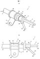
図1は、本実施の形態に係るワイヤハーネスを示す図であり、(a)は斜視図、(b)は側面図である。本実施の形態に係るワイヤハーネス1は、自動車の電動パーキングブレーキ装置にその動作のための作動電流を供給すると共に、車輪の回転速度を計測するための回転速センサ(ABS(アンチロックブレーキシステム)センサ)の信号を伝送するために用いられるものである。
(Overall configuration of wire harness)
1A and 1B are views showing a wire harness according to the present embodiment, where FIG. 1A is a perspective view and FIG. 1B is a side view. The
図1(a),(b)に示すように、ワイヤハーネス1は、複数の電線2、及び複数の電線2を一括して覆うシース31を有するケーブル3と、シース31の端部及び当該シース31の端部から延出された複数の電線2を覆うように形成され、複数の電線2の延出方向を固定する電線固定部4と、ケーブル3を被固定対象(例えば、自動車の車体)に固定する固定部材5が取り付けられる固定部材取付部6と、を備えている。
As shown in FIGS. 1A and 1B, the
(ケーブル3の構成)
図2は、ケーブル3の長手方向に垂直な断面を示す断面図である。図2に示すように、ケーブル3は、複数の電線2として、電動パーキングブレーキ装置に作動電流を供給する一対の電源線21,21と、回転速センサの信号を伝送する一対の信号線22,22と、を有している。
(
FIG. 2 is a cross-sectional view showing a cross section perpendicular to the longitudinal direction of the
一対の電源線21,21は、それぞれが複数の金属素線を撚り合せてなる金属導体線211を絶縁体212で被覆してなる絶縁電線である。一対の電源線21,21は、図略のコントローラから出力される電流を電動パーキングブレーキ装置に供給する。また、一対の信号線22,22は、それぞれが複数の金属素線を撚り合せてなる金属導体線221を絶縁体222で被覆してなる絶縁電線である。一対の信号線22,22は、回転速センサから出力される信号を図略のコントローラに伝送する。本実施の形態では、撚り合わされた一対の信号線22,22の周囲に熱可塑性ウレタンからなる内部シース231を設けることで、一対の信号線22,22を一体化した信号ケーブル23が形成されている。
The pair of
一対の電源線21,21と信号ケーブル23とは、複数の介在32と共に撚り合わされており、その周囲に紙テープ等の押え巻きテープ33が螺旋状に巻き付けられている。押え巻きテープ33の周囲には、シース31が設けられている。シース31は、配索時等に柔軟に湾曲する屈曲性(可撓性)を有しており、本実施の形態では、シース31が熱可塑性ウレタンからなる。
The pair of
(電線固定部4及び固定部材取付部6の構成)
図1(a),(b)に戻り、電線固定部4は、複数の電線2の分岐部分を覆うように設けられており、シース31と各電線2とにわたって設けられている。電線固定部4は、各電線2の延出方向を固定する役割と、電線2の分岐部分からシース31内に水分が浸入することを抑制する役割とを果たすものである。以下、シース31の端部近傍の部分の電線2を、電線2の延出部分と呼称する。
(Structure of
Returning to FIGS. 1A and 1B, the electric
電線固定部4は、シース31の端部の周囲を覆うシース囲繞部41と、電源線21,21の延出部分の周囲を一括して覆う電源線囲繞部42と、信号ケーブル23の周囲を覆う信号線囲繞部43と、を一体に有している。本実施の形態では、一対の電源線21,21の電源線囲繞部42からの延出方向は、シース囲繞部41内におけるシース31の長手方向と平行である。信号ケーブル23の信号線囲繞部43からの延出方向は、電源線21,21の電源線囲繞部42からの延出方向に対して傾斜(交差)している。信号ケーブル23は、この傾斜の角度に応じて電線固定部4内で屈曲されている。そして、この延出方向の傾斜により、自動車のタイヤハウス内での一対の電源線21,21及び信号ケーブル23の配索が容易化されている。
The electric
電線固定部4は、樹脂モールドにより形成されている。本実施の形態では、電線固定部4として、シース31と同じ樹脂材料である熱可塑性ウレタンからなるものを用いた。本実施の形態では、シース31や信号ケーブル23の内部シース231も熱可塑性ウレタンからなるため、電線固定部4の樹脂モールド時に、電線固定部4とシース31及び内部シース231とが溶融一体化(溶着)し、シース31内へ水分が侵入するのが抑制され防水性が向上する。また、電線固定部4とシース31とが溶着するため、ケーブル3の長手方向に電線固定部4が移動することを抑制することができる。
The electric
固定部材取付部6は、固定部材5が取り付けられる円筒状の取付部61と、取付部61の軸方向両端部において径方向外方に突出するようにそれぞれ設けられた円環状のフランジ部62,62と、を一体に有している。取付部61は、ケーブル3と同軸の円筒状に形成されている。フランジ部62,62は、固定部材5のケーブル長手方向(取付部61の軸方向)に沿った移動を規制するためのものである。
The fixing
固定部材取付部6は、電線固定部4と同様に、樹脂モールドにより形成されている。本実施の形態では、固定部材取付部6は、シース31及び電線固定部4と同じ樹脂材料で構成されており、熱可塑性ウレタンからなる。これにより、固定部材取付部6の樹脂モールド時に、固定部材取付部6とシース31とが溶融一体化(溶着)するため、ケーブル3の長手方向に固定部材取付部6が移動することを抑制することができる。また、電線固定部4と固定部材取付部6とを同じ樹脂材料で構成することにより、1回の樹脂成型で電線固定部4と固定部材取付部6とを同時に形成することが可能となり、製造工程の簡略化及び製造コストの低減に寄与する。
The fixing
本実施の形態では、固定部材5は、金属製の固定金具からなる。固定部材5は、取付部61の外周に加締め付けられている。固定部材5は、矩形状の金属板を屈曲して形成されており、その一端が取付部61の外周に巻き付くように湾曲されており、その他端には車体等の被固定対象への固定のためのボルトを挿通させるボルト挿通穴50が形成されている。なお、固定部材5は、金属からなるものに限らず、例えば、樹脂からなるものを用いることもできる。
In the present embodiment, the fixing member 5 is made of a metal fixing metal fitting. The fixing member 5 is crimped to the outer periphery of the mounting
本実施の形態に係るワイヤハーネス1では、電線固定部4と固定部材取付部6とが、ケーブル3の長手方向に互いに離間して設けられている。つまり、本実施の形態では、電線固定部4と固定部材取付部6とが別体となっており、電線固定部4と固定部材取付部6との間にケーブル3の一部が存在している。換言すれば、電線固定部4と固定部材取付部6とが、ケーブル3の一部を介して連結されている。
In the
これにより、電線固定部4と固定部材取付部6間のケーブル3の可撓性により、電線固定部4が固定部材取付部6に対して相対移動可能となる。そのため、固定部材5を車体等に取り付けて固定部材取付部6の位置が固定された状態となっても、電線固定部4と固定部材取付部6とのケーブル3が曲がることによって、電線固定部4の位置を動かすことが可能となり、電源線21,21や信号ケーブル23の配線作業を行い易くなる。換言すれば、本実施の形態では、各電線2(一対の電源線21,21及び信号ケーブル23)の可撓性と、ケーブル3の可撓性の両方を利用して、各電線2の端部に設けられるコネクタやセンサ部等の位置合わせを行うことができ、各電線2へのダメージを抑制しつつコネクタやセンサ部等の配設を行うことが可能である。
As a result, the flexibility of the
電線固定部4と固定部材取付部6とが近すぎると、電線固定部4と固定部材取付部6とが干渉して、配線作業の自由度が低下してしまうため、電線固定部4と固定部材取付部6とのケーブル長手方向に沿った距離Lは、電線固定部4の固定部材取付部6側の端部、すなわちシース囲繞部41の肉厚R以上であることが望ましい。電線固定部4と固定部材取付部6とのケーブル長手方向に沿った距離Lをシース囲繞部41の肉厚R以上とすることで、電線固定部4と固定部材取付部6間のケーブル3を屈曲させたとしても、電線固定部4と固定部材取付部6とが接触(干渉)しにくくなり、より電源線21,21や信号ケーブル23を配線し易くなる。
If the
また、詳細は後述するが、本実施の形態では共通の金型で電線固定部4と固定部材取付部6とを樹脂成形するため、電線固定部4と固定部材取付部6とが近すぎると、電線固定部4と固定部材取付部6とを離間させる壁(離間壁部)が薄くなり当該壁が変形し易くなってしまい、金型の寿命が低下してしまうおそれが生じる。そのため、電線固定部4と固定部材取付部6とのケーブル長手方向に沿った距離Lは、少なくとも1mm以上であるとよく、5mm以上であることがより好ましい。
Further, although the details will be described later, in the present embodiment, since the electric
さらに、本実施の形態では共通の金型で電線固定部4と固定部材取付部6とが離れすぎていると、金型が無駄に大型化し製造コストが高くなってしまう。そのため、電線固定部4と固定部材取付部6とのケーブル長手方向に沿った距離Lは、50mm以下であることが好ましい。電線固定部4と固定部材取付部6との距離Lを小さくすることによって、車両の振動に伴い電線固定部4が大きく揺れ動いてしまうことも抑制可能になる。なお、車両の振動に伴い電線固定部4が大きく揺れ動いてしまうことをより抑制するという観点から言えば、距離Lは、20mm以下であることがより好ましい。
Further, in the present embodiment, if the electric
なお、電線固定部4と固定部材取付部6とを別体とすることによって、部品点数が増加するおそれが生じるが、本実施の形態では、これら電線固定部4と固定部材取付部6を樹脂モールドにより形成しているため、実質的に部品点数の増加はなく、部品点数の増加による管理コストの増加等の問題も抑制できる。さらに、詳細は後述するが、本実施の形態では、電線固定部4と固定部材取付部6を1回の樹脂成型で形成できるため、電線固定部4や固定部材取付部6を別途作製しケーブル3に取り付ける場合と比較して、より容易にかつ短時間で製造が可能であり、量産性を向上させることができる。
By separating the
(ワイヤハーネスの製造方法)
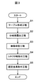
図3は、本実施の形態に係るワイヤハーネスの製造方法の手順を示すフロー図である。図3に示すように、ワイヤハーネス1を製造する際には、まず、ステップS1にて、ケーブル3を形成するケーブル形成工程を行う。その後、ステップS2にて、ケーブル3の一部のシース31及び押え巻きテープ33を除去して、電源線21,21と信号ケーブル23を露出させ、電線2の分岐の準備を行う分岐部露出工程を行う。
(Manufacturing method of wire harness)
FIG. 3 is a flow chart showing a procedure of a method for manufacturing a wire harness according to the present embodiment. As shown in FIG. 3, when manufacturing the
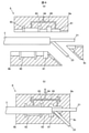
その後、ステップS3にて、電線固定部4及び固定部材取付部6を樹脂モールドにより形成する樹脂成形工程を行う。図4(a),(b)に示すように、樹脂成形工程に用いる金型8としては、電線固定部4と固定部材取付部6とをケーブル長手方向に離間させるための離間壁部83を有するものを用いる。
After that, in step S3, a resin molding step of forming the electric
金型8は、樹脂が流入することにより電線固定部4が成型される電線固定部成型部81と、樹脂が流入することにより固定部材取付部6が成型される固定部材取付部成形部82と、を有している。そして、これら電線固定部成型部81と固定部材取付部成形部82との間に、離間壁部83が形成されている。また、金型8は、1つの樹脂流入口84を有しており、この樹脂流入口84から分岐して電線固定部成型部81と固定部材取付部成形部82の両方に樹脂を導く樹脂流路85を有している。なお、図4(a),(b)では、金型8が、上型8a,第1下型8b、第2下型8cの3つの分割金型で構成される場合を示しているが、金型8の分割数はこれに限定されず、金型8の分割位置も図示の例に限定されない。
The
金型8にケーブル3をセットした状態で樹脂流入口84から樹脂を流し込むと、樹脂流路85を介して電線固定部成型部81と固定部材取付部成形部82に樹脂が流し込まれる。電線固定部成型部81と固定部材取付部成形部82に流し込まれた樹脂が冷却され硬化されると、電線固定部4及び固定部材取付部6が形成される。金型8は離間壁部83を有しているため、電線固定部4と固定部材取付部6とは、ケーブル3の長手方向に互いに離間して形成されることになる。その結果、電線固定部4と固定部材取付部6間のケーブル3の可撓性により、電線固定部4が固定部材取付部6に対して相対移動可能となる。
When the resin is poured from the
本実施の形態では、電線固定部4と固定部材取付部6が構造として別体になっているが、両者を共通の金型8を用いて1回の樹脂成形で形成できるので、製造にかかる手間を削減できる。
In the present embodiment, the electric
ステップS3の樹脂成形工程を行った後、ステップS4にて、電源線21,21や信号ケーブル23の端部にコネクタやセンサ部等を取り付けるコネクタ等取付工程を行う。その後、ステップS5にて、固定部材取付部6に固定部材5を取り付ける固定部材取付工程を行う。以上により、ワイヤハーネス1が得られる。
After performing the resin molding step of step S3, in step S4, a connector or the like attachment step of attaching a connector, a sensor portion, or the like to the end of the
(実施の形態の作用及び効果)
以上説明したように、本実施の形態に係るワイヤハーネス1では、電線固定部4及び固定部材取付部6は、樹脂モールドにより形成されており、電線固定部4と固定部材取付部6とは、ケーブル長手方向に互いに離間して設けられており、電線固定部4と固定部材取付部6間のケーブル3の可撓性により、電線固定部4が固定部材取付部6に対して相対移動可能となっている。
(Actions and effects of embodiments)
As described above, in the
このように構成することで、ケーブル3が固定部材5により車体等に固定されている場合であっても、電源線21,21と信号ケーブル23を配線し易くなる。また、車両の振動の影響を受けて電源線21,21や信号ケーブル23が振動した場合であっても、電線固定部4と固定部材取付部6間のケーブル3によって揺れを緩和して、電線固定部4からの電源線21,21及び信号ケーブル23の延出部の損傷を抑制することも可能になる。
With this configuration, even when the
(実施の形態のまとめ)
次に、以上説明した実施の形態から把握される技術思想について、実施の形態における符号等を援用して記載する。ただし、以下の記載における各符号等は、特許請求の範囲における構成要素を実施の形態に具体的に示した部材等に限定するものではない。
(Summary of embodiments)
Next, the technical idea grasped from the embodiment described above will be described with reference to the reference numerals and the like in the embodiment. However, the respective reference numerals and the like in the following description are not limited to the members and the like in which the components within the scope of the claims are specifically shown in the embodiment.
[1]複数の電線(2)、及び前記複数の電線(2)を一括して覆うシース(31)を有するケーブル(3)と、前記シース(31)の端部及び当該シース(31)の端部から延出された前記複数の電線(2)を覆うように形成され、前記複数の電線(2)の延出方向を固定する電線固定部(4)と、前記ケーブル(3)を被固定対象に固定する固定部材(7)が取り付けられる固定部材取付部(6)と、を備え、前記電線固定部(4)及び前記固定部材取付部(6)は、樹脂モールドにより形成されており、前記電線固定部(4)と前記固定部材取付部(6)とは、ケーブル長手方向に互いに離間して設けられており、前記電線固定部(4)と前記固定部材取付部(6)間の前記ケーブル(3)の可撓性により、前記電線固定部(4)が前記固定部材取付部(6)に対して相対移動可能となっている、ワイヤハーネス(1)。 [1] A cable (3) having a plurality of electric wires (2) and a sheath (31) that collectively covers the plurality of electric wires (2), an end portion of the sheath (31), and the sheath (31). A wire fixing portion (4) formed so as to cover the plurality of electric wires (2) extending from the end portion and fixing the extending direction of the plurality of electric wires (2), and the cable (3) are covered. A fixing member mounting portion (6) to which a fixing member (7) to be fixed to the fixing target is mounted is provided, and the electric wire fixing portion (4) and the fixing member mounting portion (6) are formed by a resin mold. The wire fixing portion (4) and the fixing member mounting portion (6) are provided apart from each other in the longitudinal direction of the cable, and are provided between the wire fixing portion (4) and the fixing member mounting portion (6). The wire harness (1), wherein the electric wire fixing portion (4) can move relative to the fixing member mounting portion (6) due to the flexibility of the cable (3).
[2]前記電線固定部(4)と前記固定部材取付部(6)とのケーブル長手方向に沿った距離は、前記電線固定部(4)の前記固定部材取付部(6)側の端部における前記電線固定部(4)の肉厚以上である、[1]に記載のワイヤハーネス(1)。 [2] The distance between the wire fixing portion (4) and the fixing member mounting portion (6) along the cable longitudinal direction is the end portion of the wire fixing portion (4) on the fixing member mounting portion (6) side. The wire harness (1) according to [1], which is equal to or larger than the wall thickness of the electric wire fixing portion (4) in the above.
[3]前記電線固定部(4)と前記固定部材取付部(6)とのケーブル長手方向に沿った距離が、1mm以上である、[1]または[2]に記載のワイヤハーネス(1)。 [3] The wire harness (1) according to [1] or [2], wherein the distance between the electric wire fixing portion (4) and the fixing member mounting portion (6) along the cable longitudinal direction is 1 mm or more. ..
[4]前記電線固定部(4)と前記固定部材取付部(6)とは、同じ樹脂材料で構成されている、[1]乃至[3]の何れか1項に記載のワイヤハーネス(1)。 [4] The wire harness (1) according to any one of [1] to [3], wherein the electric wire fixing portion (4) and the fixing member mounting portion (6) are made of the same resin material. ).
[5]複数の電線(2)、及び前記複数の電線(2)を一括して覆うシース(31)を有するケーブル(3)と、前記シース(3)の端部及び当該シース(3)の端部から延出された前記複数の電線(2)を覆うように形成され、前記複数の電線(2)の延出方向を固定する電線固定部(4)と、前記ケーブル(3)を被固定対象に固定する固定部材(7)が取り付けられる固定部材取付部(6)と、を備えたワイヤハーネス(1)を製造する方法であって、前記電線固定部(4)及び前記固定部材取付部(6)を、樹脂モールドにより形成する樹脂成型工程を含み、前記樹脂成型工程に用いる金型(8)として、前記電線固定部(4)と前記固定部材取付部(6)とをケーブル長手方向に離間させるための離間壁部(83)を有するものを用い、前記電線固定部(4)と前記固定部材取付部(6)とを、ケーブル長手方向に互いに離間させ、前記電線固定部(4)と前記固定部材取付部(6)間の前記ケーブル(3)の可撓性により、前記電線固定部(4)を前記固定部材取付部(6)に対して相対移動可能とする、ワイヤハーネスの製造方法。 [5] A cable (3) having a plurality of electric wires (2) and a sheath (31) that collectively covers the plurality of electric wires (2), an end portion of the sheath (3), and the sheath (3). A wire fixing portion (4) formed so as to cover the plurality of electric wires (2) extending from the end portion and fixing the extending direction of the plurality of electric wires (2), and the cable (3) are covered. It is a method of manufacturing a wire harness (1) provided with a fixing member mounting portion (6) to which a fixing member (7) to be fixed to a fixing target is attached, wherein the electric wire fixing portion (4) and the fixing member are attached. The portion (6) includes a resin molding step of forming by a resin mold, and as a mold (8) used in the resin molding step, the electric wire fixing portion (4) and the fixing member mounting portion (6) are connected to each other by a cable length. Using a device having a separation wall portion (83) for separating in the direction, the wire fixing portion (4) and the fixing member mounting portion (6) are separated from each other in the cable longitudinal direction, and the wire fixing portion ( A wire that allows the wire fixing portion (4) to move relative to the fixing member mounting portion (6) due to the flexibility of the cable (3) between the fixing member mounting portion (6) and the fixing member mounting portion (6). How to make a harness.
[6]前記金型(8)は、樹脂が流入することにより前記電線固定部(4)が成型される電線固定部成型部(81)と、樹脂が流入することにより前記固定部材取付部(6)が成型される固定部材取付部成形部(82)と、樹脂流入口(84)から分岐して前記電線固定部成型部(81)と前記固定部材取付部成形部(82)の両方に樹脂を導く樹脂流路(85)と、を有する、[5]に記載のワイヤハーネスの製造方法。 [6] The mold (8) has a wire fixing portion molded portion (81) in which the wire fixing portion (4) is molded by the inflow of resin, and the fixing member mounting portion (81) in which the resin flows in. 6) is molded into both the fixed member mounting portion molding portion (82) and the electric wire fixing portion molding portion (81) and the fixing member mounting portion molding portion (82) branched from the resin inlet (84). The method for manufacturing a wire harness according to [5], which has a resin flow path (85) for guiding a resin.
以上、本発明の実施の形態を説明したが、上記に記載した実施の形態は特許請求の範囲に係る発明を限定するものではない。また、実施の形態の中で説明した特徴の組合せの全てが発明の課題を解決するための手段に必須であるとは限らない点に留意すべきである。 Although the embodiments of the present invention have been described above, the embodiments described above do not limit the invention according to the claims. It should also be noted that not all combinations of features described in the embodiments are essential to the means for solving the problems of the invention.
本発明は、その趣旨を逸脱しない範囲で適宜変形して実施することが可能である。例えば、上記実施の形態では、一対の信号線22,22の周囲に内部シース231を設けて信号ケーブル23を形成する場合について説明したが、これに限らず、内部シース231を省略して、シース31の端部から一対の信号線22,22が延出されるように構成してもよい。
The present invention can be appropriately modified and implemented without departing from the spirit of the present invention. For example, in the above embodiment, the case where the
また、上記実施の形態では、ワイヤハーネス1が1つの固定部材取付部6を備えている場合について説明したが、ワイヤハーネス1は、複数の固定部材取付部6を備えていてもよい。この場合、最も電線固定部4に近い固定部材取付部6と、電線固定部4とが、ケーブル長手方向に互いに離間して設けられていればよい。
Further, in the above embodiment, the case where the
1…ワイヤハーネス
2…電線
3…ケーブル
31…シース
4…電線固定部
5…固定部材
6…固定部材取付部
8…金型
81…電線固定部成型部
82…固定部材取付部成形部
83…離間壁部
84…樹脂流入口
85…樹脂流路
1 ...
Claims (6)
前記シースの端部及び当該シースの端部から延出された前記複数の電線を覆うように形成され、前記複数の電線の延出方向を固定する電線固定部と、
前記ケーブルを被固定対象に固定する固定部材が取り付けられる固定部材取付部と、
を備え、
前記電線固定部及び前記固定部材取付部は、樹脂モールドにより形成されており、
前記電線固定部と前記固定部材取付部とは、ケーブル長手方向に互いに離間して設けられており、前記電線固定部と前記固定部材取付部間の前記ケーブルの可撓性により、前記電線固定部が前記固定部材取付部に対して相対移動可能となっており、
前記シースと前記電線固定部と前記固定部材取付部とは、同じ樹脂材料で構成されており、
前記シースと前記電線固定部とが溶着しているとともに、前記シースと前記固定部材取付部とが溶着している、
ワイヤハーネス。 A cable having a sheath that collectively covers a plurality of electric wires and the plurality of electric wires, and
An electric wire fixing portion formed so as to cover the end portion of the sheath and the plurality of electric wires extending from the end portion of the sheath and fixing the extending direction of the plurality of electric wires.
A fixing member mounting portion to which a fixing member for fixing the cable to the object to be fixed is mounted, and a fixing member mounting portion.
Equipped with
The electric wire fixing portion and the fixing member mounting portion are formed of a resin mold.
The wire fixing portion and the fixing member mounting portion are provided apart from each other in the longitudinal direction of the cable, and the wire fixing portion is provided due to the flexibility of the cable between the wire fixing portion and the fixing member mounting portion. Is movable relative to the fixing member mounting portion.
The sheath, the wire fixing portion, and the fixing member mounting portion are made of the same resin material.
The sheath and the electric wire fixing portion are welded together, and the sheath and the fixing member mounting portion are welded together.
Wire harness.
請求項1に記載のワイヤハーネス。 The distance between the wire fixing portion and the fixing member mounting portion along the cable longitudinal direction is equal to or larger than the wall thickness of the wire fixing portion at the end portion of the wire fixing portion on the fixing member mounting portion side.
The wire harness according to claim 1.
請求項1または2に記載のワイヤハーネス。 The distance between the electric wire fixing portion and the fixing member mounting portion along the cable longitudinal direction is 1 mm or more.
The wire harness according to claim 1 or 2.
請求項1乃至3の何れか1項に記載のワイヤハーネス。 The sheath, the wire fixing portion, and the fixing member mounting portion are made of thermoplastic urethane.
The wire harness according to any one of claims 1 to 3.
前記シースの端部及び当該シースの端部から延出された前記複数の電線を覆うように形成され、前記複数の電線の延出方向を固定する電線固定部と、
前記ケーブルを被固定対象に固定する固定部材が取り付けられる固定部材取付部と、
を備え、
前記シースと前記電線固定部と前記固定部材取付部とが同じ樹脂材料で構成されているワイヤハーネスを製造する方法であって、
前記電線固定部及び前記固定部材取付部を、樹脂モールドにより形成する樹脂成型工程を含み、
前記樹脂成型工程に用いる金型として、前記電線固定部と前記固定部材取付部とをケーブル長手方向に離間させるための離間壁部を有するものを用い、
前記電線固定部と前記固定部材取付部とを、ケーブル長手方向に互いに離間させ、前記電線固定部と前記固定部材取付部間の前記ケーブルの可撓性により、前記電線固定部を前記固定部材取付部に対して相対移動可能とし、
前記シースと前記電線固定部とを溶着させるとともに、前記シースと前記固定部材取付部とを溶着させる、
ワイヤハーネスの製造方法。 A cable having a sheath that collectively covers a plurality of electric wires and the plurality of electric wires, and
An electric wire fixing portion formed so as to cover the end portion of the sheath and the plurality of electric wires extending from the end portion of the sheath and fixing the extending direction of the plurality of electric wires.
A fixing member mounting portion to which a fixing member for fixing the cable to the object to be fixed is mounted, and a fixing member mounting portion.
Equipped with
A method for manufacturing a wire harness in which the sheath, the wire fixing portion, and the fixing member mounting portion are made of the same resin material .
A resin molding step of forming the electric wire fixing portion and the fixing member mounting portion by a resin molding is included.
As the mold used in the resin molding step, a mold having a separating wall portion for separating the electric wire fixing portion and the fixing member mounting portion in the longitudinal direction of the cable is used.
The wire fixing portion and the fixing member mounting portion are separated from each other in the longitudinal direction of the cable, and the wire fixing portion is mounted on the fixing member due to the flexibility of the cable between the wire fixing portion and the fixing member mounting portion. It is possible to move relative to the part,
The sheath and the electric wire fixing portion are welded together, and the sheath and the fixing member mounting portion are welded together.
How to make a wire harness.
樹脂が流入することにより前記電線固定部が成型される電線固定部成型部と、
樹脂が流入することにより前記固定部材取付部が成型される固定部材取付部成形部と、
樹脂流入口から分岐して前記電線固定部成型部と前記固定部材取付部成形部の両方に樹脂を導く樹脂流路と、を有する、
請求項5に記載のワイヤハーネスの製造方法。 The mold is
The wire fixing part molded part, in which the wire fixing part is molded by the inflow of resin,
The fixed member mounting part molded part, in which the fixing member mounting part is molded by the inflow of resin,
It has a resin flow path that branches from the resin inlet and guides the resin to both the electric wire fixing portion molded portion and the fixing member mounting portion molded portion.
The method for manufacturing a wire harness according to claim 5.
Priority Applications (4)
| Application Number | Priority Date | Filing Date | Title |
|---|---|---|---|
| JP2018091897A JP6996416B2 (en) | 2018-05-11 | 2018-05-11 | Wire harness and its manufacturing method |
| US16/392,308 US10501030B2 (en) | 2018-05-11 | 2019-04-23 | Wire harness and method for manufacturing the same |
| CN201910346430.1A CN110473665B (en) | 2018-05-11 | 2019-04-26 | Wire harness and method for manufacturing same |
| JP2021199779A JP7238949B2 (en) | 2018-05-11 | 2021-12-09 | wire harness |
Applications Claiming Priority (1)
| Application Number | Priority Date | Filing Date | Title |
|---|---|---|---|
| JP2018091897A JP6996416B2 (en) | 2018-05-11 | 2018-05-11 | Wire harness and its manufacturing method |
Related Child Applications (1)
| Application Number | Title | Priority Date | Filing Date |
|---|---|---|---|
| JP2021199779A Division JP7238949B2 (en) | 2018-05-11 | 2021-12-09 | wire harness |
Publications (2)
| Publication Number | Publication Date |
|---|---|
| JP2019197687A JP2019197687A (en) | 2019-11-14 |
| JP6996416B2 true JP6996416B2 (en) | 2022-01-17 |
Family
ID=68463851
Family Applications (1)
| Application Number | Title | Priority Date | Filing Date |
|---|---|---|---|
| JP2018091897A Active JP6996416B2 (en) | 2018-05-11 | 2018-05-11 | Wire harness and its manufacturing method |
Country Status (3)
| Country | Link |
|---|---|
| US (1) | US10501030B2 (en) |
| JP (1) | JP6996416B2 (en) |
| CN (1) | CN110473665B (en) |
Families Citing this family (13)
| Publication number | Priority date | Publication date | Assignee | Title |
|---|---|---|---|---|
| US10688944B2 (en) * | 2017-08-24 | 2020-06-23 | Fca Us Llc | Integrated liftgate wire harness tether |
| JP7279422B2 (en) * | 2019-03-07 | 2023-05-23 | 株式会社プロテリアル | Composite cable and composite harness |
| US20210015512A1 (en) * | 2019-07-16 | 2021-01-21 | Covidien Lp | Sensor encapsulating assembly |
| JP7447499B2 (en) * | 2020-01-21 | 2024-03-12 | 住友電装株式会社 | wiring parts |
| JP7415589B2 (en) * | 2020-01-24 | 2024-01-17 | 住友電装株式会社 | wiring parts |
| JP7331754B2 (en) * | 2020-03-30 | 2023-08-23 | 株式会社プロテリアル | wire harness |
| JP7216044B2 (en) * | 2020-04-24 | 2023-01-31 | 矢崎総業株式会社 | Method for molding waterproof member |
| JP7424205B2 (en) * | 2020-05-21 | 2024-01-30 | 株式会社プロテリアル | wire harness |
| JP7472739B2 (en) * | 2020-09-24 | 2024-04-23 | 住友電装株式会社 | Wire Harness |
| JP7480721B2 (en) * | 2021-02-12 | 2024-05-10 | 住友電装株式会社 | Wire Harness |
| CN115579665B (en) * | 2022-11-23 | 2023-03-10 | 工牛电缆河北有限公司 | Prefabricated branch cable |
| JP2024149131A (en) * | 2023-04-07 | 2024-10-18 | 株式会社プロテリアル | Wire Harness |
| US12586694B2 (en) * | 2024-01-09 | 2026-03-24 | Sumitomo Electric Industries, Ltd. | Multicore cable |
Citations (1)
| Publication number | Priority date | Publication date | Assignee | Title |
|---|---|---|---|---|
| JP2018507810A (en) | 2015-02-23 | 2018-03-22 | コンティネンタル・テーベス・アクチエンゲゼルシヤフト・ウント・コンパニー・オッフェネ・ハンデルスゲゼルシヤフト | Seal mold split structure for combination cable and method for manufacturing the same |
Family Cites Families (20)
| Publication number | Priority date | Publication date | Assignee | Title |
|---|---|---|---|---|
| US3617614A (en) | 1970-01-14 | 1971-11-02 | Wilsons Sons Inc William M | Explosion-proof electrical connector and cable assembly |
| JP3200016B2 (en) * | 1996-06-14 | 2001-08-20 | 株式会社小糸製作所 | Bushing molding method and molding die for vehicle lighting cord, and structure of bushing |
| JP3691291B2 (en) | 1999-06-28 | 2005-09-07 | 矢崎総業株式会社 | Waterproof connector |
| JP4440223B2 (en) * | 2006-02-15 | 2010-03-24 | 矢崎総業株式会社 | Corrugated tube fixing structure |
| TW201108258A (en) * | 2009-04-24 | 2011-03-01 | Sumitomo Electric Industries | Electrical wire and method for manufacturing the same |
| EP2355286B1 (en) | 2010-01-29 | 2019-04-03 | CommScope Connectivity Belgium BVBA | Cable sealing and retaining device |
| JP5541331B2 (en) * | 2012-04-20 | 2014-07-09 | 日立金属株式会社 | Composite harness |
| JP6013117B2 (en) * | 2012-09-28 | 2016-10-25 | 矢崎総業株式会社 | Manufacturing method of wire harness |
| WO2014103499A1 (en) * | 2012-12-28 | 2014-07-03 | 住友電装株式会社 | Wheel speed sensor and wire harness |
| DE102014003976A1 (en) | 2014-03-20 | 2015-09-24 | Man Truck & Bus Ag | Connection arrangement and corresponding method |
| JP6256218B2 (en) * | 2014-06-17 | 2018-01-10 | 日立金属株式会社 | Manufacturing method of cable with resin molded body and cable with resin molded body |
| JP6281461B2 (en) * | 2014-09-30 | 2018-02-21 | 日立金属株式会社 | Manufacturing method of cable with resin mold |
| JP6213447B2 (en) | 2014-10-31 | 2017-10-18 | 住友電装株式会社 | Harness |
| JP6245145B2 (en) * | 2014-11-18 | 2017-12-13 | 株式会社オートネットワーク技術研究所 | Electric wire with mold part and method of manufacturing electric wire with mold part |
| JP6059263B2 (en) * | 2015-01-30 | 2017-01-11 | 矢崎総業株式会社 | Wire integrated clamp mark and wire harness |
| JP6311938B2 (en) | 2015-03-02 | 2018-04-18 | 株式会社オートネットワーク技術研究所 | Multi-core cable seal structure |
| JP5943170B1 (en) * | 2015-09-14 | 2016-06-29 | 日立金属株式会社 | Composite cable and composite harness |
| JP6736870B2 (en) * | 2015-11-26 | 2020-08-05 | 住友電装株式会社 | Conductive path |
| CN206401056U (en) * | 2016-01-21 | 2017-08-11 | 日立金属株式会社 | composite harness and composite cable |
| JP6834275B2 (en) * | 2016-09-13 | 2021-02-24 | 日立金属株式会社 | Wire harness |
-
2018
- 2018-05-11 JP JP2018091897A patent/JP6996416B2/en active Active
-
2019
- 2019-04-23 US US16/392,308 patent/US10501030B2/en active Active
- 2019-04-26 CN CN201910346430.1A patent/CN110473665B/en active Active
Patent Citations (1)
| Publication number | Priority date | Publication date | Assignee | Title |
|---|---|---|---|---|
| JP2018507810A (en) | 2015-02-23 | 2018-03-22 | コンティネンタル・テーベス・アクチエンゲゼルシヤフト・ウント・コンパニー・オッフェネ・ハンデルスゲゼルシヤフト | Seal mold split structure for combination cable and method for manufacturing the same |
Also Published As
| Publication number | Publication date |
|---|---|
| US10501030B2 (en) | 2019-12-10 |
| US20190344733A1 (en) | 2019-11-14 |
| CN110473665A (en) | 2019-11-19 |
| CN110473665B (en) | 2022-08-12 |
| JP2019197687A (en) | 2019-11-14 |
Similar Documents
| Publication | Publication Date | Title |
|---|---|---|
| JP6996416B2 (en) | Wire harness and its manufacturing method | |
| JP7180435B2 (en) | wire harness | |
| CN110232991B (en) | Cable bundle | |
| CN111029994B (en) | Wiring member | |
| KR101638422B1 (en) | Seal mold divided structure for combination cable and method for manufacturing the same | |
| JP7031551B2 (en) | Wiring member | |
| JP7206849B2 (en) | wire harness | |
| JP2020077631A (en) | Composite harness | |
| US11242015B2 (en) | Vehicle wire harness with sheath covering cables | |
| CN111029012A (en) | Wiring member | |
| JP7238949B2 (en) | wire harness | |
| JP7183988B2 (en) | wire harness | |
| JP7327117B2 (en) | Wiring material | |
| JP7322612B2 (en) | vehicle wiring harness | |
| JP7236618B2 (en) | wire harness | |
| JP2021121140A (en) | Cable assembly | |
| JP7014111B2 (en) | Wire harness | |
| JP7111132B2 (en) | Wiring material | |
| JP7327624B2 (en) | wire harness | |
| JP7395829B2 (en) | Wire harness manufacturing method | |
| US20250018885A1 (en) | Wire harness | |
| JP7316815B2 (en) | wire harness | |
| JP2025012328A (en) | Wire Harness | |
| JP7236617B2 (en) | wire harness | |
| JP6700626B2 (en) | Composite harness |
Legal Events
| Date | Code | Title | Description |
|---|---|---|---|
| A621 | Written request for application examination |
Free format text: JAPANESE INTERMEDIATE CODE: A621 Effective date: 20201204 |
|
| A977 | Report on retrieval |
Free format text: JAPANESE INTERMEDIATE CODE: A971007 Effective date: 20210804 |
|
| A131 | Notification of reasons for refusal |
Free format text: JAPANESE INTERMEDIATE CODE: A131 Effective date: 20210907 |
|
| A521 | Request for written amendment filed |
Free format text: JAPANESE INTERMEDIATE CODE: A523 Effective date: 20211104 |
|
| TRDD | Decision of grant or rejection written | ||
| A01 | Written decision to grant a patent or to grant a registration (utility model) |
Free format text: JAPANESE INTERMEDIATE CODE: A01 Effective date: 20211116 |
|
| A61 | First payment of annual fees (during grant procedure) |
Free format text: JAPANESE INTERMEDIATE CODE: A61 Effective date: 20211129 |
|
| R150 | Certificate of patent or registration of utility model |
Ref document number: 6996416 Country of ref document: JP Free format text: JAPANESE INTERMEDIATE CODE: R150 |
|
| S531 | Written request for registration of change of domicile |
Free format text: JAPANESE INTERMEDIATE CODE: R313531 |
|
| S533 | Written request for registration of change of name |
Free format text: JAPANESE INTERMEDIATE CODE: R313533 |
|
| R350 | Written notification of registration of transfer |
Free format text: JAPANESE INTERMEDIATE CODE: R350 |