JP6996412B2 - Electromagnetic relay - Google Patents
Electromagnetic relay Download PDFInfo
- Publication number
- JP6996412B2 JP6996412B2 JP2018085586A JP2018085586A JP6996412B2 JP 6996412 B2 JP6996412 B2 JP 6996412B2 JP 2018085586 A JP2018085586 A JP 2018085586A JP 2018085586 A JP2018085586 A JP 2018085586A JP 6996412 B2 JP6996412 B2 JP 6996412B2
- Authority
- JP
- Japan
- Prior art keywords
- contact
- movable contact
- fixed
- yoke
- movable
- Prior art date
- Legal status (The legal status is an assumption and is not a legal conclusion. Google has not performed a legal analysis and makes no representation as to the accuracy of the status listed.)
- Active
Links
Images


Landscapes
- Arc-Extinguishing Devices That Are Switches (AREA)
Description
本発明は、可動接点と固定接点とを接離させて電気回路を開閉する電磁継電器に関するものである。 The present invention relates to an electromagnetic relay that opens and closes an electric circuit by bringing a movable contact and a fixed contact into contact with each other.
高電圧バッテリとインバータとを備える車両において、電磁継電器はインバータへの電源供給のオン・オフを行う役割を果たす。電磁継電器は、2つの固定接点を有する固定端子と、2つの固定接点に対応する2つの可動接点を有する可動子を備えた構造とされ、可動子を移動させて可動接点と固定接点とを接離させることにより、電気回路をオン・オフする。可動接点と固定接点とが当接して電気的に導通しているとき、この状態でインバータの短絡故障などによって接点部に数千アンペアの短絡電流が流れると、接点間または固定子と可動子との間には接点部を開離させようとする反発力(以下、電磁反発力という)が作用する。しかしながら、電磁継電器とは別途備えたヒューズによる電流遮断が行われるように、リレーには電磁反発力が作用する短絡故障時にも接点部が開離しないことが要求される。 In a vehicle equipped with a high voltage battery and an inverter, an electromagnetic relay plays a role of turning on / off the power supply to the inverter. The electromagnetic relay has a structure equipped with a fixed terminal having two fixed contacts and a mover having two movable contacts corresponding to the two fixed contacts, and the movable element is moved to connect the movable contact and the fixed contact. By separating it, the electric circuit is turned on and off. When the movable contact and the fixed contact are in contact with each other and are electrically conductive, if a short-circuit current of several thousand amperes flows through the contact due to a short-circuit failure of the inverter in this state, the contact between the contacts or the stator and the mover A repulsive force (hereinafter referred to as an electromagnetic repulsive force) that tries to open the contact portion acts between them. However, the relay is required not to open the contact portion even in the case of a short-circuit failure in which an electromagnetic repulsive force acts so that the current is cut off by a fuse provided separately from the electromagnetic relay.
また、電磁継電器には、接点部に生じるアークを消弧するため消弧用磁石が備えられており、フレミングの左手の法則に基づく電磁力、つまりローレンツ力をアークに作用させて力の方向を変化させることで消弧できるようになっている。 In addition, the electromagnetic relay is equipped with an arc-extinguishing magnet to extinguish the arc generated at the contact part, and the electromagnetic force based on Fleming's left-hand rule, that is, the Lorentz force is applied to the arc to change the direction of the force. It can be extinguished by changing it.
例えば、特許文献1において、接点部に生じるアークを消弧するための消弧用磁石が発生する磁束を利用して、可動接点と固定接点との接点部の開離を抑制することができる電磁継電器が提案されている。この電磁継電器では、可動子に消弧用磁石と対向する対向板部を設け、対向板部を流れる電流と消弧用磁石の磁束により発生するローレンツ力が、可動接点と固定接点とを当接させる向きとなるようにし、接点部の開離を抑制する。
For example, in
また、可動子に可動ヨークを設けると共に、それに対向する固定子に固定ヨークを設け、可動子の電流により生じる磁束を利用し、ヨーク間で吸引力を発生させる構造もある。このように、ヨーク間に発生させられる吸引力に基づいて、可動接点と固定接点との接点部の開離を抑制することもできる。 Further, there is also a structure in which a movable yoke is provided on the movable element and a fixed yoke is provided on the stator facing the movable element, and the magnetic flux generated by the current of the movable element is used to generate an attractive force between the yokes. In this way, it is possible to suppress the separation of the contact portion between the movable contact and the fixed contact based on the suction force generated between the yokes.
しかしながら、近年の大電流化に伴ってリレーに流れる電流が増加し、電磁反発力の増加が生じており、この電磁反発力の増加に伴ってローレンツ力の向上が求められる場合、高磁束密度の磁石が必要になる。 However, the current flowing through the relay increases with the increase in current in recent years, and the electromagnetic repulsive force increases. When the Lorentz force is required to be improved with the increase in the electromagnetic repulsive force, the magnetic flux density is high. You will need a magnet.
また、電磁反発力の増加に伴ってヨーク間吸引力の向上が求められる場合、可動ヨークの磁気飽和を回避するために可動ヨークの体格が大型化し、可動子の重量が増加することで、アーク遮断性能の低下などに繋がる。 In addition, when the suction force between the yokes is required to be improved due to the increase in the electromagnetic repulsive force, the size of the movable yoke is increased in order to avoid magnetic saturation of the movable yoke, and the weight of the movable element is increased, so that the arc is formed. It leads to deterioration of blocking performance.
本発明は上記点に鑑みて、可動子の重量増加を抑えつつ、高磁束密度の磁石を用いなくてもローレンツ力を向上させて、接点部の開離を抑制できる電磁継電器を提供することを目的とする。 In view of the above points, the present invention provides an electromagnetic relay capable of suppressing the increase in the weight of the mover, improving the Lorentz force without using a magnet having a high magnetic flux density, and suppressing the separation of the contact portion. The purpose.
上記目的を達成するため、請求項1に記載の発明は、通電時に磁界を形成する励磁コイル(12)と、可動接点(29、30)を有し、励磁コイルへの通電に基づいて移動させられる可動接触子(20)と、励磁コイルへの通電時に可動接触子が移動させられると、可動接点と接する固定接点(27、28)を有する固定端子(25、26)と、可動接点と固定接点とが当接するオン状態から、可動接点と固定接点とが離れるオフ状態に切り替わるときに接点部に発生するアークを消弧するための消弧用磁石(23、231、232)と、消弧用磁石の一方の磁極に対向配置された一端および該一端から消弧用磁石からの磁束が導かれる他端を有し、該他端が可動接点と固定接点との接点部を介して消弧用磁石の他方の磁極に対向配置された集磁ヨーク(24、241、242)と、を備えている。そして、このような構成において、オン状態の時に、可動接点と固定接点との接点部を介し、可動接触子を通じて固定端子に電流を流し、可動接触子を流れる電流と集磁ヨークにより導かれた磁束とによって、可動接点と固定接点とが当接する方向にローレンツ力を発生させる。
In order to achieve the above object, the invention according to
このように、集磁ヨークの一端が消弧用磁石の一方の磁極に対向させられると共に他端が固定接点を介して消弧用磁石の他方の磁極に対向させられている。これにより、可動接触子に一体化されたヨークを設けなくても、十分に接点部の開離を抑制する方向のローレンツ力を発生させることが可能となる。このため、可動子の重量増加を抑えることが可能となる。よって、可動子の重量増加を抑えつつ、高磁束密度の磁石を用いなくてもローレンツ力を向上させて、接点部の開離を抑制できる電磁継電器とすることが可能となる。 In this way, one end of the magnetic collecting yoke is opposed to one magnetic pole of the arc-extinguishing magnet, and the other end is opposed to the other magnetic pole of the arc-extinguishing magnet via a fixed contact. This makes it possible to generate a Lorentz force in a direction that sufficiently suppresses the opening of the contact portion without providing a yoke integrated with the movable contact. Therefore, it is possible to suppress an increase in the weight of the movable element. Therefore, it is possible to obtain an electromagnetic relay capable of suppressing the opening and closing of the contact portion by improving the Lorentz force without using a magnet having a high magnetic flux density while suppressing an increase in the weight of the mover.
なお、各構成要素等に付された括弧付きの参照符号は、その構成要素等と後述する実施形態に記載の具体的な構成要素等との対応関係の一例を示すものである。 The reference numerals in parentheses attached to each component or the like indicate an example of the correspondence between the component or the like and the specific component or the like described in the embodiment described later.
以下、本発明の実施形態について図に基づいて説明する。なお、以下の各実施形態相互において、互いに同一もしくは均等である部分には、同一符号を付して説明を行う。 Hereinafter, embodiments of the present invention will be described with reference to the drawings. In each of the following embodiments, the parts that are the same or equal to each other will be described with the same reference numerals.
(第1実施形態)
第1実施形態について説明する。図1~図3を参照して本実施形態の電磁継電器について説明する。なお、便宜上、図1の紙面上方向、紙面下方向および紙面左右方向を、それぞれ、電磁継電器の上方向、下方向および左右方向として説明するが、必ずしも電磁継電器の使用時の天地方向と一致することを意味している訳ではない。
(First Embodiment)
The first embodiment will be described. The electromagnetic relay of the present embodiment will be described with reference to FIGS. 1 to 3. For convenience, the upward direction, the downward direction of the paper surface, and the left-right direction of the paper surface in FIG. 1 are described as the upward direction, the downward direction, and the left-right direction of the electromagnetic relay, respectively, but they always coincide with the top-bottom direction when the electromagnetic relay is used. It doesn't mean that.
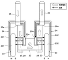
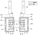
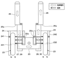
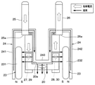
図1に示すように、電磁継電器は、ケース11、励磁コイル12、固定コア13、ヨーク14、可動コア15、復帰バネ16、シャフト17、ベース18、絶縁樹脂19、可動接触子20、支持枠21、接圧バネ22、消弧用磁石23および集磁ヨーク24を備える。
As shown in FIG. 1, the electromagnetic relay includes a
ケース11は、例えば樹脂等の非磁性かつ非導電性の材料で構成されている。ケース11内に構成される空間内に、電磁継電器を構成する各部品が収容されている。
The
励磁コイル12は、通電時に磁界を形成するもので、略円筒状とされ、中空状の円筒部を有するボビン12aに巻回されている。この励磁コイル12への通電は図示しない外部接続端子を通じて行われるようになっている。励磁コイル12の内径部に形成された中心孔に、固定コア13等が配置されている。
The
固定コア13は、磁性体よりなり、励磁コイル12の中心孔と対応する大きさの略円柱状部材で構成されており、磁気回路の一部を構成する。固定コア13は、中心軸に沿って貫通孔13aが形成された構造とされており、この貫通孔13a内にシャフト17の一端が位置している。
The
ヨーク14は、励磁コイル12を囲む磁性体部材である。ヨーク14は、励磁コイル12の外周側および軸方向端部の一方を覆うように配置され、磁気回路の一部を構成すると共に、軸方向の一方側で固定コア13の位置に対応する開口部となるヨーク孔142aが形成されたものとして構成される。
The
本実施形態の場合、ヨーク14は、第1部材141と第2部材142とを有した構成とされている。第1部材141は、ステーショナリと呼ばれる部材であり、磁性体よりなる板材を略U字状に折り曲げた構造とされている。この第1部材141によって励磁コイル12の外周側および励磁コイル12の軸方向一端側が覆われている。また、第2部材142は、トッププレートと呼ばれる部材であり、磁性体よりなり、例えば円形平板もしくは矩形平板状で構成され、励磁コイル12の軸方向他端側を覆っている。また、第2部材142は、後述する可動コア15に対向して配置されており、第1部材141と接合されている。
In the case of the present embodiment, the
第1部材141には、固定コア13と対応する位置に開口部141aが形成されており、この開口部141a内に固定コア13の一部が嵌め込まれることで固定コア13と第1部材141とが接合されている。第2部材142には、中心部に上記したヨーク孔142aが第2部材142を貫通するように形成されている。ヨーク孔142aの形状、つまり第2部材142の内周形状は、可動コア15と対応する形状とされている。
An
可動コア15は、第2部材142におけるヨーク孔142aと対応する位置に配置された磁性体よりなる円盤状部材である。可動コア15の中心軸線上において後述するシャフト17が挿入される貫通孔15aが形成されている。可動コア15は、励磁コイル12への通電が行われていない非通電時には、ヨーク14から離れた休止位置に位置しており、励磁コイル12への通電を行う通電時には、ヨーク14側に磁気吸引されて、ヨーク14の第2部材142に当接させられる。可動コア15の外周形状は、ヨーク孔142aの内周形状と対応した形状となっており、固定コア13と反対側が固定コア13側よりも径が拡大されたフランジ状とされ、そのフランジ状部分がヨーク孔142aの内壁面に当接させられるようになっている。
The
また、本実施形態では、可動コア15のうちの復帰バネ16側の一面に、復帰バネ16が嵌め込まれるストッパ部15bが備えられている。ストッパ部15bは、可動コア15のうち復帰バネ16側の一面から円環状に突き出した突起部によって構成とされ、その外周面に復帰バネ16が嵌め込まれている。
Further, in the present embodiment, a
復帰バネ16は、固定コア13と励磁コイル12の内壁面の段差部との間に配置され、可動コア15を固定コア13と反対側に付勢する。励磁コイル12への通電を行う通電時には、電磁吸引力により可動コア15は復帰バネ16に抗して固定コア13側に吸引されるようになっている。
The
このように、固定コア13、ヨーク14および可動コア15が磁性体によって構成されており、励磁コイル12へ通電を行う通電時には、これらによって励磁コイル12により誘起された磁束の磁気回路が構成される。
As described above, the fixed
シャフト17は、例えば非磁性材料で構成されており、可動コア15に結合されることで可動コア15と一体的に移動可能とされている。より詳細には、シャフト17は、可動コア15に形成された貫通孔15aに挿入された状態で可動コア15に結合されている。そして、シャフト17のうちの一端が固定コア13側に突き出し、固定コア13に形成された貫通孔13a内に入り込んだ状態となっている。
The shaft 17 is made of, for example, a non-magnetic material, and is made movable integrally with the
また、シャフト17のうち可動コア15における固定コア13側の一面と対応する位置に、シャフト17の一部の外径を拡大したフランジ部17aが形成されている。励磁コイル12への通電時に、可動コア15がフランジ部17aを押すことで、シャフト17が固定コア13側に移動させられるようになっている。
Further, a
さらに、シャフト17のうち固定コア13と反対側の一端には、絶縁樹脂19が装着されている。そして、絶縁樹脂19が可動接触子20に当接させられており、シャフト17の軸方向における可動接触子20の位置決めが行われる。
Further, an insulating
なお、本実施形態の場合、励磁コイル12への通電、非通電によって、可動コア15、シャフト17、絶縁樹脂19、可動接触子20等が進退させられる可動部分となる。
In the case of the present embodiment, the
ベース18は、非磁性体の絶縁性材料、例えば樹脂によって構成されており、ケース11に固定されている。ベース18は、中央部に開口部18aが形成されており、この開口部18a内にシャフト17や絶縁樹脂19が挿通されている。ベース18は、ヨーク14に接した状態でケース11に固定されている。そして、ベース18には、導電金属製の板状の第1固定端子25および第2固定端子26が備えられている。
The
本実施形態では、図1~図3に示すように、第1固定端子25および第2固定端子26は、図1および図3の紙面向こう側、つまり図2の紙面上方に向けて引き出されている。この部分を通じて、第1固定端子25および第2固定端子26が外部配線などに接続されるようになっている。また、第1固定端子25および第2固定端子26は、外部に引き出される途中位置において、図1および図3の紙面上方、つまり可動接触子20側に向かって折れ曲がった折曲部25a、26aを有した構造とされている。
In the present embodiment, as shown in FIGS. 1 to 3, the first fixed
これら第1固定端子25および第2固定端子26が、電磁継電器によってオンオフ制御を行う対象となる電気回路の配線の一部を構成するものである。さらに、第1固定端子25に接続されるように第1固定接点27が取り付けられ、第2固定端子26に接続されるように第2固定接点28が取り付けられている。上記した折曲部25a、26aは、それぞれ、第1固定接点27や第2固定接点28よりも図2の紙面上方側に設けられ、図2の紙面手前側に折曲げられ、さらに紙面上方側に折曲げられたものとされている。
These first fixed
なおベース18のうち可動コア15と対向する一面は、ストッパー18bとなっており、可動コア15の固定コア13と反対側への移動が規制されるようになっている。
One side of the base 18 facing the
可動接触子20は、可動コア15に追従作動させられるものであり、導電金属製の板状部材で構成され、例えばシャフト17を中心とした対称位置に、導電金属製の2つの可動接点として第1可動接点29および第2可動接点30が固定されている。
The
また、可動接触子20は、シャフト17のうち固定コア13に挿入された端部と反対となる他端側に配置されている。可動接触子20のうち固定コア13側の一面は絶縁樹脂19に接しており、絶縁樹脂19の位置に可動接触子20が位置決め配置されている。
Further, the
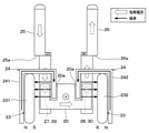
また、図2に示すように、可動接触子20は、第1切欠部に相当する切欠部20aが形成されており、第1可動接点29と第2可動接点30との間に切欠部20aが位置することで、可動接触子20に可動子電流が流される際には、切欠部20aを迂回して流れるようになっている。すなわち、可動接触子20のうち切欠部20aよりも外側の部位が、第1可動接点29と第2可動接点30との間の電流経路の距離を引き延ばす延設部となる。そして、延設部での電流の流れ、換言すれば第1可動接点29や第2可動接点30を通る電流の流れが図2の紙面上下方向とほぼ平行となる。
Further, as shown in FIG. 2, the
本実施形態の場合、可動接触子20を長方形状の板状部材で構成しつつ、図2の紙面上方側の一辺より、長方形状の中心を挟むようにして2本の切欠部20aを形成している。このため、例えば長方形状の中心位置において、絶縁樹脂19が当接させられ、その両側に切欠部20aが位置するようになっている。このような構造の可動接触子20については、板材の折曲げ、打ち抜き、もしくは、切欠き加工によって容易に製造可能である。
In the case of the present embodiment, the
支持枠21は、ケース11に固定され、ベース18に当接させられている。支持枠21の中央位置には、環状溝21aが形成されており、接圧バネ22の一端側が嵌め込まれることで、接圧バネ22が支持されている。
The
接圧バネ22は、可動接触子20と支持枠21との間に配置されており、可動接触子20をシャフト17側、すなわち第1固定接点27および第2固定接点28側に付勢している。
The
このため、可動コア15の移動に伴ってシャフト17および絶縁樹脂19が移動させられると、接圧バネ22の弾性力に基づいて可動接触子20も追従させられるようになっている。また、第1可動接点29および第2可動接点30が第1固定接点27および第2固定接点28と当接させられているときに振動等が生じても、第1可動接点29と第1固定接点27および第2可動接点30と第2固定接点28との接続が維持される。
Therefore, when the shaft 17 and the insulating
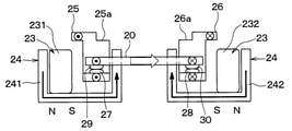
消弧用磁石23は、オン状態からオフ状態に切り替わるときに接点部に生じるアークを消弧するために設けられるもので、フレミングの左手の法則に基づく電磁力、つまりローレンツ力をアークに作用させて力の方向を変化させることでアークの消弧を行う。本実施形態では、消弧用磁石23は、第1固定接点27および第2固定接点28を挟み込むように、これらの両側それぞれに配置された第1磁石231と第2磁石232とによって構成されている。
The arc-extinguishing
第1磁石231および第2磁石232は、共に、N極が第1固定接点27および第2固定接点28と反対側に向けられ、S極が第1固定接点27および第2固定接点28側に向けられるように配置されている。
In both the
さらに、本実施形態では、これら第1磁石231および第2磁石232が発生する磁束と後述する集磁ヨーク24とを利用して、第1可動接点29と第1固定接点27の接点部および第2可動接点30と第2固定接点28との接点部の開離を抑制する役割も果たす。
Further, in the present embodiment, the magnetic flux generated by the
集磁ヨーク24は、消弧用磁石23の一方の磁極から発生した磁束をもう一方の磁極に導くためのものであり、軟磁性体で構成される。集磁ヨーク24は、U字型とされた板状部材で構成され、第1固定接点27および第1磁石231の周囲に配置された第1ヨーク241と、第2固定接点28および第2磁石232の周囲に配置された第2ヨーク242とを有した構成とされている。
The
図2に示すように、第1ヨーク241は、一端が第1磁石231のN極に対向させられており、他端が第1固定接点27を挟んで第1磁石231のS極に対向させられている。より詳しくは、第1ヨーク241は、一端が第1磁石231のN極に接するように配置され、U字状の底部において第1固定端子25の折曲部25aよりも第1固定接点27から離れた位置を迂回して、他端が可動接触子20の切欠部20a内に入り込んでいる。そして、第1ヨーク241の他端は、第1固定端子25のうちの第1固定接点27が配置される部分、ここでは折曲部25aよりも第1固定接点27側の部分と同方向に延設されている。
As shown in FIG. 2, one end of the
第2ヨーク242は、一端が第2磁石232のN極に対向させられており、他端が第2固定接点28を挟んで第2磁石232のS極に対向させられている。より詳しくは、第2ヨーク242は、一端が第2磁石232のN極に接するように配置され、U字状の底部において第2固定端子26の折曲部26aよりも第2固定接点28から離れた位置を迂回して、他端が可動接触子20の切欠部20a内に入り込んでいる。そして、第2ヨーク242の他端は、第2固定端子26のうちの第2固定接点28が配置される部分、ここでは折曲部26aよりも第2固定接点28側の部分と同方向に延設されている。
One end of the
以上のような構造により、本実施形態にかかる電磁継電器が構成されている。続いて、このように構成された電磁継電器の作動について説明する。 The electromagnetic relay according to the present embodiment is configured by the above structure. Subsequently, the operation of the electromagnetic relay configured in this way will be described.
まず、励磁コイル12への通電が行われていない際には、励磁コイル12への通電に基づく磁気回路が形成されず、可動コア15が固定コア13側に磁気吸引されない。このため、可動コア15や可動接触子20などの可動部分は図1に示す位置に配置された状態となり、第1可動接点29や第2可動接点30が第1固定接点27や第2固定接点28から離れた状態となる。したがって、第1固定端子25と第2固定端子26との間が電気的に分離された状態となり、電磁継電器がオフ状態となる。
First, when the
続いて、電磁継電器をオン状態にする際には励磁コイル12への通電が行われる。このため、励磁コイル12への通電に基づいて誘起された磁束の磁気回路が形成され、可動コア15が固定コア13側に磁気吸引される。そして、可動コア15が固定コア13側に磁気吸引されると、可動接触子20が当接している絶縁樹脂19も固定コア13側に移動させられることから、可動接触子20や第1可動接点29および第2可動接点30も接圧バネ22の弾性力に基づき、可動コア15に追従して移動する。
Subsequently, when the electromagnetic relay is turned on, the
したがって、第1可動接点29および第2可動接点30が第1固定接点27および第2固定接点28と当接して、第1固定接点27と第2固定接点28との間が電気的に導通させられる。そして、第1固定端子25と第2固定端子26との間が導通させられ、電磁継電器がオン状態となる。これにより、第1固定端子25や第2固定端子26それぞれに接続された外部配線などが導通させられ、図2中の白抜き矢印の電流経路が形成される。
Therefore, the first
また、電磁継電器をオン状態からオフ状態に切り替える際には、励磁コイル12への通電が遮断される。これにより、励磁コイル12の通電に基づいて発生させられていた磁気吸引力が解除される。このため、復帰バネ16の弾性力に基づいて可動コア15が固定コア13と反対側に移動させられる。したがって、第1可動接点29および第2可動接点30が第1固定接点27および第2固定接点28から離れ、第1固定接点27と第2固定接点28との間の電気的接続が遮断され、電磁継電器がオフ状態となる。なお、インバータ等の短絡故障などが生じた際に電磁反発力を発生させる短絡電流の経路もこの電流経路となる。
Further, when the electromagnetic relay is switched from the on state to the off state, the energization to the
このような動作を行うに際し、上記したように、本実施形態の電磁継電器では、第1ヨーク241の一端が第1磁石231のN極に対向し、他端が第1固定接点27を挟んで第1磁石231のS極に対向するようにしている。より詳しくは、可動接触子20のうち第1固定接点27および第1可動接点29から紙面下方に向かって延設された延設部を挟むように第1ヨーク241を配置している。このため、第1磁石231から発生される磁束が第1ヨーク241によって導かれ、図2中の実線矢印のように流れる。すなわち、第1磁石231のN極から発生させられた磁束は、第1ヨーク241の一端から他端に導かれ、さらに第1ヨーク241の他端から第1磁石231のS極に向かう。
In performing such an operation, as described above, in the electromagnetic relay of the present embodiment, one end of the
同様に、第2ヨーク242の一端が第2磁石232のN極に対向し、他端が第2固定接点28を挟んで第2磁石232のS極に対向するようにしている。より詳しくは、可動接触子20のうち第2固定接点28および第2可動接点30から紙面下方に向かって延設された延設部を挟むように第2ヨーク242を配置している。このため、第2磁石232から発生される磁束が第2ヨーク242によって導かれ、図2中の実線矢印のように流れる。すなわち、第2磁石232のN極から発生させられた磁束は、第2ヨーク242の一端から他端に導かれ、さらに第2ヨーク242の他端から第2磁石232のS極に向かう。
Similarly, one end of the
したがって、集磁ヨーク24によって導いた磁束を可動接触子20に流れる可動子電流に効果的に鎖交させることができ、下向きのローレンツ力を発生させられる。つまり、第1可動接点29や第2可動接点30を第1固定接点27や第2固定接点28側に付勢する力を発生させることができる。特に、可動接触子20のうち切欠部20aよりも外側の延設部において図2の紙面上下方向と平行、つまり磁束と交差する向き、好ましくは直交する向きに電流を流すことができる。このように、延設部を設けて磁束に対して交差する電流成分を効率的に得ることで、より上記効果が得られる。
Therefore, the magnetic flux induced by the magnetic collecting
さらに、集磁ヨーク24が第1固定端子25および第2固定端子26における折曲部25a、26aよりも外側を迂回する構造とされている。このため、第1固定端子25および第2固定端子26に流れる電流により、これらの周囲に生じる磁束も集磁することができる。このため、さらに可動接触子20や第1可動接点29および第2可動接点30に鎖交する磁束量を高められ、上記ローレンツ力を高めることが可能となる。
Further, the magnetic collecting
また、従来、空間に放出していた磁束を集磁ヨーク24によって集め、可動接触子20や第1可動接点29および第2可動接点30に鎖交させることができるため、アーク遮断性能の向上も図ることができる。
Further, since the magnetic flux conventionally emitted into the space can be collected by the magnetic collecting
以上説明したように、本実施形態の電磁継電器では、集磁ヨーク24の一端が消弧用磁石23のN極に対向させられると共に他端が第1固定接点27もしくは第2固定接点28を介して消弧用磁石23のS極に対向させられている。これにより、可動接触子20に一体化されたヨークを設けなくても、十分に接点部の開離を抑制する方向のローレンツ力を発生させることが可能となる。このため、可動子の重量増加を抑えることが可能となる。よって、可動子の重量増加を抑えつつ、高磁束密度の磁石を用いなくてもローレンツ力を向上させて、接点部の開離を抑制できる電磁継電器とすることが可能となる。また、可動子の重量増加が抑えられることにより、接点部の開離時の開離速度を高めることができ、アーク遮断時の接点摩耗を抑制することも可能となる。さらに、2つの接点部それぞれにおいて、集磁ヨーク24を備えた構造としているため、可動接触子20の左右方向の両側において同様の効果を得ることができる。
As described above, in the electromagnetic relay of the present embodiment, one end of the magnetic collecting
また、第1ヨーク241の他端から第1磁石231に向かう磁束の向きと第1固定端子25のうち第1固定接点27側の部分に電流が流れたときに生じる磁束の向きとが、同じ向きとなる。同様に、第2ヨーク242の他端から第2磁石232に向かう磁束の向きと第2固定端子26のうち第2固定接点28側の部分に電流が流れたときに生じる磁束の向きとが、同じ向きとなる。したがって、可動接触子20に流れる可動子電流に対して鎖交する磁束量を高められ、より大きな下向きのローレンツ力を発生させることが可能となる。
Further, the direction of the magnetic flux from the other end of the
さらに、集磁ヨーク24は、SPCC等の打ち抜きや折曲げ加工によって容易に製作でき、例えば板幅は数mmであるため、接点部の体格増加を最小限に抑制することが可能となる。
Further, the magnetic collecting
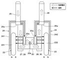
(第1実施形態の変形例)
上記第1実施形態に対して、第1ヨーク241および第2ヨーク242の構成を変更しても良い。具体的には、図4に示すように、第1ヨーク241が第1固定接点27の折曲部25aよりも第1固定接点27側を通るようにする。同様に、第2ヨーク242が第2固定接点28の折曲部26aよりも第2固定接点28側を通るようにする。
(Variation example of the first embodiment)
The configurations of the
このような構成とする場合、第1ヨーク241が折曲部25aよりも第1固定接点27から離れる側を迂回せず、第2ヨーク242が折曲部26aよりも第2固定接点28から離れる側を迂回しない。このため、集磁ヨーク24内において、消弧用磁石23の磁束と第1固定端子25および第2固定端子26に流れる固定子電流の磁束が互いに逆向きで打ち消し合う。したがって、第1実施形態と比較すると接点部で鎖交する磁束量が減少するものの、ほぼ第1実施形態と同様の効果を得ることができる。
In such a configuration, the
(第2実施形態)
第2実施形態について説明する。本実施形態は、第1実施形態に対して可動接触子20の構成を変更したものであり、その他については第1実施形態と同様であるため、第1実施形態と異なる部分についてのみ説明する。
(Second Embodiment)
The second embodiment will be described. This embodiment is a modification of the configuration of the
図5に示すように、本実施形態では、可動接触子20に対して、切欠部20aに加えて、さらに切欠部20bを形成している。切欠部20bは、第2切欠部に相当するものであり、2本の切欠部20aの間、具体的には可動接触子20の長手方向の中央位置において、可動接触子20のうち切欠部20aが形成された一辺と対向する一辺より形成されている。
As shown in FIG. 5, in the present embodiment, the
このように、可動接触子20の中央位置に切欠部20bを設けるようにしている。このため、集磁ヨーク24の先端から遠い側の消弧用磁石23に向かう磁束と、図5中に矢印で示したような可動接触子20の中央部での可動子電流間で、図5の紙面向こう側のローレンツ力を得ることができる。したがって、第1可動接点29や第2可動接点30を第1固定接点27や第2固定接点28に付勢する力を高めることが可能となり、さらに接点部の開離を抑制することが可能となる。
In this way, the
(第3実施形態)
第3実施形態について説明する。本実施形態も、第1実施形態に対して可動接触子20の構成を変更したものであり、その他については第1実施形態と同様であるため、第1実施形態と異なる部分についてのみ説明する。
(Third Embodiment)
The third embodiment will be described. This embodiment is also a modification of the configuration of the
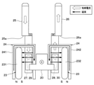
図6および図7に示すように、本実施形態では、可動接触子20のうち第1可動接点29と第2可動接点30との間の部分を、上方向、つまり固定コア13から離れる方向に突出させた凸部としている。そして、第1ヨーク241や第2ヨーク242の他端が凸部の内側を通過して可動接触子20よりも突き出した状態になっている。
As shown in FIGS. 6 and 7, in the present embodiment, the portion of the
このような構造とすれば、集磁ヨーク24の他端が消弧用磁石23と対向する面積を大きくすることができる。これにより、さらに可動接触子20や第1可動接点29および第2可動接点30に鎖交する磁束量を高められ、上記ローレンツ力を高めることが可能となると共に、アーク遮断性能の向上を図ることが可能となる。
With such a structure, the area where the other end of the magnetic collecting
(第3実施形態の変形例)
上記第3実施形態において、図8に示すように集磁ヨーク24を環状構造としても良い。具体的には、第1ヨーク241が一端から他端に至るまでに、接点部に対して図8の紙面上方を回り込んだ部分に加えて、紙面下方を回り込んだ部分を有した構成とされている。また、第2ヨーク242が一端から他端に至るまでに、接点部に対して図8の紙面上方を回り込んだ部分に加えて、紙面下方を回り込んだ部分を有した構成とされている。
(Modified example of the third embodiment)
In the third embodiment, the magnetic collecting
このような構造とすれば、図中に示したように、磁束が消弧用磁石23を挟んで紙面上方と下方を回り込む双方を通じて流れるようにでき、消弧用磁石23の表面から可動接触子20側への磁気抵抗を低減することができる。
With such a structure, as shown in the figure, the magnetic flux can flow through both the upper side and the lower side of the paper surface with the arc-extinguishing
なお、第3実施形態および上記した図8の構造においても、第1実施形態のように、第1ヨーク241および第2ヨーク242が、折曲部25a、26aよりも第1固定接点27や第2固定接点28から離れた位置を迂回した構造とされていても良い。
In addition, also in the third embodiment and the structure of FIG. 8 described above, as in the first embodiment, the
(第4実施形態)
第4実施形態について説明する。本実施形態は、第1実施形態に対して集磁ヨーク24の構成を変更したものであり、その他については第1実施形態と同様であるため、第1実施形態と異なる部分についてのみ説明する。
(Fourth Embodiment)
The fourth embodiment will be described. Since the present embodiment is the same as the first embodiment in that the configuration of the magnetic collecting
図9および図10に示すように、本実施形態では、集磁ヨーク24を接点部の下方を通る構造としている。具体的には、第1ヨーク241は、第1磁石231のN極と対向配置された一端から第1磁石231および第1固定接点27と第1可動接点29との接点部の下方を通り、接点部を挟んで第1磁石231の反対側の他端に至る構造とされている。第2ヨーク242は、第2磁石232のN極と対向配置された一端から第2磁石232および第2固定接点28と第2可動接点30との接点部の下方を通り、接点部を挟んで第2磁石232の反対側の他端に至る構造とされている。
As shown in FIGS. 9 and 10, in the present embodiment, the magnetic collecting
このような構造とすることで、第1固定端子25および第2固定端子26の引き出し方向、つまり図9の紙面上方に集磁ヨーク24を引き回すためのスペースが必要なくなり、当該方向での電磁継電器の体格の増加を抑制することができる。また、各接点部の下方を通るように集磁ヨーク24を備えた構造とすることで、集磁ヨーク24内の消弧用磁石23の磁束と固定子電流の磁束の向きを一致させることができるため、両者の磁束が打ち消し合うこと無くローレンツ力の向上が図れる。したがって、さらに接点部の開離を抑制することが可能となる。
With such a structure, there is no need for a space for routing the magnetic collecting
(第5実施形態)
第5実施形態について説明する。本実施形態は、第1実施形態に対して可動接触子20および集磁ヨーク24の構成を変更したものであり、その他については第1実施形態と同様であるため、第1実施形態と異なる部分についてのみ説明する。
(Fifth Embodiment)
A fifth embodiment will be described. This embodiment is different from the first embodiment because the configurations of the
図11に示すように、本実施形態では、集磁ヨーク24を一部材で構成している。具体的には、第1ヨーク241と第2ヨーク242との他端同士を連結部243で連結した構成としている。連結部243は第1磁石231および第2磁石232のS極の表面の法線方向に伸びる構成とされている。また、可動接触子20の切欠部20aを1つとし、連結部243が入り込む構成にすると共に、切欠部20aの底部において、可動接触子20と連結部243とが対向するようにしている。
As shown in FIG. 11, in the present embodiment, the magnetic collecting
このような構成によれば、集磁ヨーク24を一部材にできることから部品点数の削減を図ることが可能となる。また、図11中に示したように、連結部243において発生させられる漏れ磁束と可動接触子20に流れる可動子電流が鎖交するため、上記各実施形態と比較して、可動接触子20の中央部においても下向きのローレンツ力を発生させることが可能となる。したがって、さらに接点部の開離を抑制することが可能となる。
According to such a configuration, since the magnetic collecting
(第5実施形態の変形例)
上記第5実施形態では、集磁ヨーク24を一部材で構成する場合について説明したが、図12に示すように、さらに可動接触子20を挟んで連結部243と反対側に、連結部243と対向するように集磁ヨーク244を備えることもできる。この集磁ヨーク244は、対向ヨークであり、長方形板状の軟磁性体で構成され、図12に示すように電磁継電器の上方から見ると直線状となっている。このような集磁ヨーク244を備えることで、連結部243から集磁ヨーク244に向かう磁束量を増やすこと、つまり可動接触子20に鎖交する磁束量を増やすことができる。したがって、可動接触子20の中央部での下向きのローレンツ力を増加させられ、さらに接点部の開離を抑制することが可能となる。
(Variation example of the fifth embodiment)
In the fifth embodiment, the case where the magnetic collecting
(第6実施形態)
第6実施形態について説明する。本実施形態は、第1実施形態に対して消弧用磁石23や集磁ヨーク24の構成を変更したものであり、その他については第1実施形態と同様であるため、第1実施形態と異なる部分についてのみ説明する。
(Sixth Embodiment)
The sixth embodiment will be described. This embodiment is different from the first embodiment because the configurations of the arc-extinguishing
本実施形態では、図13に示すように、消弧用磁石23を1つのみとし、可動接触子20の中央部に対向して配置されている。ここでは、N極が可動接触子20の中央部に向けられ、S極が可動接触子20の中央部と反対側に向けられるようにして消弧用磁石23が配置されている。
In the present embodiment, as shown in FIG. 13, only one arc-extinguishing
また、集磁ヨーク24は、消弧用磁石23と可動接触子20との間に配置された第1ヨーク245と、消弧用磁石23を挟んで可動接触子20と反対側に配置された第2ヨーク246とによって構成されている。
Further, the magnetic collecting
第1ヨーク245は、一端と他端がそれぞれ2つの切欠部20aの一方と他方に入り込むコの字形状の部材で構成されている。
The
第2ヨーク246も、コの字形状の部材で構成されており、第1ヨーク245の周りに配置されていて、第1ヨーク245よりも大きなものとされている。具体的には、第2ヨーク246は、一端が第1固定接点27と第1可動接点29との接点部を挟んで第1ヨーク245の一端と対向するように配置され、他端が第2固定接点28と第2可動接点30との接点部を挟んで第2ヨーク246の他端と対向するように配置されている。
The
このような構成においては、各接点部を第1ヨーク245と第2ヨーク246とによって挟むように配置していることから、第1ヨーク245の各端部から第2ヨーク246の各端部に向かう磁束を発生させられる。つまり、各接点部での磁束を上記各実施形態と同じにしつつ、消弧用磁石23を1つにすることが可能になる。このように、消弧用磁石23の個数を削減できるため、接点部近傍の体格の大幅な小型化を図ることが可能となる。
In such a configuration, since each contact portion is arranged so as to be sandwiched between the
(第6実施形態の変形例)
上記第6実施形態において、図14に示すように、第2ヨーク246を第1固定端子25の折曲部25aや第2固定端子26の折曲部26aよりも可動接触子20から離れる側を迂回する構造とすることもできる。このようにすれば、第2ヨーク246内を流れる消弧用磁石23の磁束と第1固定端子25および第2固定端子26に流れる固定子電流の磁束の向きを一致させることができる。したがって、第6実施形態よりも可動接触子20への鎖交磁束を高めることが可能となり、下向きのローレンツ力の向上とアーク遮断性能の向上を図ることが可能となる。
(Modified example of the sixth embodiment)
In the sixth embodiment, as shown in FIG. 14, the side of the
(第7実施形態)
第7実施形態について説明する。本実施形態は、第1~第4実施形態に対して第1固定端子25と第2固定端子26の引き出し方向を逆方向としたものであり、その他については第1~第4実施形態と同様であるため、第1~第4実施形態と異なる部分についてのみ説明する。なお、ここでは第1実施形態に対して本実施形態の構造とした場合について説明するが、第2~第4実施形態についても適用可能である。
(7th Embodiment)
The seventh embodiment will be described. In the present embodiment, the drawing directions of the first fixed
図15に示すように、第1固定端子25は紙面上方に引き出されており、第2固定端子26は紙面下方に引き出されている。
As shown in FIG. 15, the first fixed
可動接触子20は、長方形状とされつつ、一辺に切欠部20cが設けられ、その一辺と相対する一辺に切欠部20dが設けられている。切欠部20cと切欠部20dとは、可動接触子20の中心に対して対称的に配置され、可動接触子20が回転対称形状となっている。
The
第1ヨーク241は、U字型とされた板状部材で構成され、第1固定接点27および第1磁石231の周囲に配置されている。そして、一端が第1磁石231のN極に対向配置され、他端が第1固定接点27を介して第1磁石231のS極に対向配置されると共に切欠部20cに入り込む構成としてある。また、第2ヨーク242は、U字型とされた板状部材で構成され、第2固定接点28および第2磁石232の周囲に配置されている。そして、一端が第2磁石232のN極に対向配置され、他端が第2固定接点28を介して第2磁石232のS極に対向配置されると共に切欠部20dに入り込む構成としてある。
The
このような構成としても、集磁ヨーク24によって導いた磁束を可動接触子20に流れる可動子電流に効果的に鎖交させることができ、下向きのローレンツ力を発生させられる。したがって、第1実施形態と同様の効果を得ることができる。
Even with such a configuration, the magnetic flux induced by the magnetic collecting
(第8実施形態)
第8実施形態について説明する。本実施形態は、第1~第7実施形態に対して接点部を3点にしたものであり、その他については第1~第7実施形態と同様であるため、第1~第7実施形態と異なる部分についてのみ説明する。なお、ここでは第1実施形態に対して本実施形態の構造とした場合について説明するが、第2~第7実施形態についても適用可能である。
(8th Embodiment)
The eighth embodiment will be described. This embodiment has three contact points with respect to the first to seventh embodiments, and the other points are the same as those of the first to seventh embodiments. Only the different parts will be described. Although the case where the structure of the present embodiment is adopted with respect to the first embodiment is described here, the second to seventh embodiments can also be applied.
図16に示すように、本実施形態にかかる電磁継電器は、第1固定接点27および第2固定接点28に加えて第3固定接点31を備え、さらに第1可動接点29および第2可動接点30に加えて第3可動接点32を備えた構成とされている。第3可動接点32は、第2可動接点30と共に可動接触子20のうち切欠部20aの外側に位置する延設部に配置され、延設部の延設方向において第2可動接点30と共に並んで配置されている。
As shown in FIG. 16, the electromagnetic relay according to the present embodiment includes a third fixed contact 31 in addition to the first fixed
第3固定接点31は、第2固定接点28に対して、図16の紙面下方、つまり第1固定接点27と第2固定接点28とを結ぶ直線よりも下方位置に配置されている。同様に、第3可動接点32は、第2可動接点30に対して、図16の紙面下方、つまり第1可動接点29と第2可動接点30とを結ぶ直線よりも下方位置に配置されている。これにより、第1固定接点27と第1可動接点29との接点部と、第2固定接点28と第2可動接点30との接点部と、第3固定接点31と第3可動接点32との接点部の3点の接点部を有した構成となる。
The third fixed contact 31 is arranged below the paper surface of FIG. 16, that is, below the straight line connecting the first fixed
このように、3点の接点部を有した構成とされると、第1実施形態と同様の効果が得られるのに加えて、可動接触子20の揺動を抑制することが可能になる。また、第3固定接点31と第3可動接点32との接点部を通じても可動接触子20より第2固定端子26に電流が流れ込むようになる。このため、第3固定接点31と第3可動接点32との接点部から第2固定接点28と第2可動接点30との接点部の間においては、可動接触子20と第2固定端子26の双方に同方向の電流が流れる。このため、これらの間に流れる電流による吸引力を発生させることが可能になり、より接点部の開離を抑制することが可能となる。
As described above, when the configuration has the three contact points, the same effect as that of the first embodiment can be obtained, and the swing of the
(他の実施形態)
本発明は上記した実施形態に限定されるものではなく、特許請求の範囲に記載した範囲内において適宜変更が可能である。
(Other embodiments)
The present invention is not limited to the above-described embodiment, and can be appropriately modified within the scope of the claims.
(1)例えば、上記実施形態では、第1固定端子25に別部材の第1固定接点27を備え、第2固定端子26に別部材の第2固定接点28を備えた。しかしながら、第1固定端子25および第2固定端子26に、可動接触子20側に向かって突出する突起部を例えばプレス加工にて形成し、その突起部を固定接点としてもよい。また、第8実施形態で説明した第3固定接点31についても同様である。
(1) For example, in the above embodiment, the first fixed
(2)同様に、上記実施形態では、可動接触子20に別部材の第1可動接点29や第2可動接点30をかしめ固定した。しかしながら、可動接触子20に、第1固定端子25および第2固定端子26側に向かって突出する突起部を例えばプレス加工にて形成し、その突起部を可動接点としてもよい。また、第8実施形態で説明した第3可動接点32についても同様である。
(2) Similarly, in the above embodiment, the first
(3)また、可動接触子20や第1固定端子25および第2固定端子26の形状についても一例を挙げたに過ぎない。
(3) Further, the shapes of the
12 励磁コイル
13 固定コア
15 可動コア
22 可動接触子
23 消弧用磁石
24 集磁ヨーク
24、25 第1、第2固定端子
26、27、31 第1~第3固定接点
28、29、32 第1~第3可動接点
12
Claims (11)
可動接点(29、30)を有し、前記励磁コイルへの通電に基づいて移動させられる可動接触子(20)と、
前記励磁コイルへの通電時に前記可動接触子が移動させられると、前記可動接点と接する固定接点(27、29)を有する固定端子(25、26)と、
前記可動接点と前記固定接点とが当接するオン状態から、前記可動接点と前記固定接点とが離れるオフ状態に切り替わるときに接点部に発生するアークを消弧するための消弧用磁石(23、231、232)と、
前記消弧用磁石の一方の磁極に対向配置された一端および該一端から前記消弧用磁石からの磁束が導かれる他端を有し、該他端が前記可動接点と前記固定接点との接点部を介して前記消弧用磁石の他方の磁極に対向配置された集磁ヨーク(24、241、242)と、を備え、
前記オン状態の時に、前記可動接点と前記固定接点との接点部を介し、前記可動接触子を通じて前記固定端子に電流を流し、
前記可動接触子を流れる電流と前記集磁ヨークにより導かれた磁束とによって、前記可動接点と前記固定接点とが当接する方向にローレンツ力を発生させる電磁継電器。 An exciting coil (12) that forms a magnetic field when energized,
A movable contact (20) having movable contacts (29, 30) and being moved based on energization of the exciting coil.
When the movable contact is moved when the exciting coil is energized, a fixed terminal (25, 26) having a fixed contact (27, 29) in contact with the movable contact,
An arc-extinguishing magnet (23, 231 and 232) and
It has one end arranged to face one of the magnetic poles of the arc-extinguishing magnet and the other end from which the magnetic flux from the arc-extinguishing magnet is guided, and the other end is the contact point between the movable contact and the fixed contact. A magnetic flux collecting yoke (24, 241 and 242) arranged to face the other magnetic pole of the arc-extinguishing magnet via a portion is provided.
In the on state, a current is passed through the movable contact via the contact portion between the movable contact and the fixed contact, and a current is passed through the fixed terminal.
An electromagnetic relay that generates Lorentz force in the direction in which the movable contact and the fixed contact come into contact with each other by the current flowing through the movable contact and the magnetic flux guided by the magnetic collecting yoke.
第1可動接点(29)および第2可動接点(30)を有し、前記励磁コイルへの通電に基づいて移動させられる可動接触子(20)と、
前記励磁コイルへの通電時に前記可動接触子が移動させられると、前記第1可動接点と接する第1固定接点(27)を有する第1固定端子(25)、および、前記第2可動接点と接する第2固定接点(28)を有する第2固定端子(26)と、
前記第1可動接点と前記第1固定接点とが当接すると共に前記第2可動接点と前記第2固定接点とが当接するオン状態から、前記第1可動接点と前記第1固定接点とが離れると共に前記第2可動接点と前記第2固定接点とが離れるオフ状態に切り替わるときに接点部に発生するアークを消弧するための第1磁石(231)と第2磁石(232)とを有する消弧用磁石(23)と、
前記第1磁石の一方の磁極に対向配置された一端および該一端から前記第1磁石からの磁束が導かれる他端を有し、該他端が前記第1可動接点と前記第1固定接点との接点部を介して前記第1磁石の他方の磁極に対向配置された第1ヨーク(241)と、前記第2磁石の一方の磁極に対向配置された一端および該一端から前記第2磁石からの磁束が導かれる他端を有し、該他端が前記第2可動接点と前記第2固定接点との接点部を介して前記第2磁石の他方の磁極に対向配置された第2ヨーク(242)と、を有する集磁ヨーク(24)と、を備え、
前記オン状態の時に、前記第1可動接点と前記第1固定接点との接点部および前記第2可動接点と前記第2固定接点との接点部を介し、前記可動接触子を通じて、前記第1固定端子と前記第2固定端子との間に電流を流し、
前記可動接触子を流れる電流と前記集磁ヨークにより導かれた磁束とによって、前記第1可動接点と前記第1固定接点とが当接すると共に前記第2可動接点と前記第2固定接点とが当接する方向にローレンツ力を発生させる電磁継電器。 An exciting coil (12) that forms a magnetic field when energized,
A movable contact (20) having a first movable contact (29) and a second movable contact (30) and moved based on energization of the exciting coil.
When the movable contact is moved when the exciting coil is energized, it comes into contact with the first fixed terminal (25) having the first fixed contact (27) in contact with the first movable contact and the second movable contact. A second fixed terminal (26) having a second fixed contact (28),
The first movable contact and the first fixed contact are separated from the on state in which the first movable contact and the first fixed contact are in contact with each other and the second movable contact and the second fixed contact are in contact with each other. An arc extinguishing having a first magnet (231) and a second magnet (232) for extinguishing an arc generated in the contact portion when the second movable contact and the second fixed contact are switched to an off state in which they are separated from each other. Magnet (23) and
It has one end arranged to face one of the magnetic poles of the first magnet and the other end to which the magnetic flux from the first magnet is guided from the one end, and the other end is the first movable contact and the first fixed contact. The first yoke (241) arranged to face the other magnetic flux of the first magnet, one end arranged to face one of the magnetic poles of the second magnet, and the second magnet from the one end via the contact portion of the first magnet. A second yoke having the other end to which the magnetic flux of the magnet is guided, the other end of which is arranged to face the other magnetic pole of the second magnet via the contact portion between the second movable contact and the second fixed contact. 242) and a magnetic flux collecting yoke (24) having the
In the on state, the first fixed contact portion is passed through the contact portion between the first movable contact and the first fixed contact and the contact portion between the second movable contact and the second fixed contact, and through the movable contact element. A current is passed between the terminal and the second fixed terminal,
The current flowing through the movable contact and the magnetic flux guided by the magnetic collecting yoke bring the first movable contact and the first fixed contact into contact with each other, and the second movable contact and the second fixed contact come into contact with each other. An electromagnetic relay that generates Lorentz force in the direction of contact.
前記第2固定端子は、前記第2固定接点に加えて前記第3可動接点に当接させられる第3固定接点(31)を有し、
前記第2可動接点および前記第3可動接点は、前記延設部の延設方向に並んで配置されている請求項5に記載の電磁継電器。 The movable contact has a third movable contact (32) in addition to the first movable contact and the second movable contact.
The second fixed terminal has a third fixed contact (31) that is brought into contact with the third movable contact in addition to the second fixed contact.
The electromagnetic relay according to claim 5, wherein the second movable contact and the third movable contact are arranged side by side in the extension direction of the extension portion.
前記第2固定端子のうち前記第2固定接点が配置される部分は、該部分に電流が流れたときに生じる磁束の向きと、前記第2ヨークの他端から前記第2磁石に向かう磁束の向きとが揃う方向に延設されている請求項4ないし6のいずれか1つに記載の電磁継電器。 The portion of the first fixed terminal where the first fixed contact is arranged is the direction of the magnetic flux generated when a current flows through the portion and the magnetic flux from the other end of the first yoke toward the first magnet. It is extended in the direction that the direction is aligned,
The portion of the second fixed terminal where the second fixed contact is arranged is the direction of the magnetic flux generated when a current flows through the portion and the magnetic flux from the other end of the second yoke toward the second magnet. The electromagnetic relay according to any one of claims 4 to 6, which is extended in a direction in which the directions are aligned.
前記第2固定端子は、前記可動接触子側に向かって折り曲がった折曲部(26a)を有し、前記第2ヨークは、前記第2固定端子の折曲部よりも前記第2固定接点から離れた位置を迂回して配置されている請求項4ないし9のいずれか1つに記載の電磁継電器。 The first fixed terminal has a bent portion (25a) bent toward the movable contact side, and the first yoke has the first fixed contact rather than the bent portion of the first fixed terminal. It is located around the location away from
The second fixed terminal has a bent portion (26a) bent toward the movable contact side, and the second yoke has the second fixed contact rather than the bent portion of the second fixed terminal. The electromagnetic relay according to any one of claims 4 to 9, which is arranged by detouring a position away from.
Priority Applications (1)
| Application Number | Priority Date | Filing Date | Title |
|---|---|---|---|
| JP2018085586A JP6996412B2 (en) | 2018-04-26 | 2018-04-26 | Electromagnetic relay |
Applications Claiming Priority (1)
| Application Number | Priority Date | Filing Date | Title |
|---|---|---|---|
| JP2018085586A JP6996412B2 (en) | 2018-04-26 | 2018-04-26 | Electromagnetic relay |
Publications (2)
| Publication Number | Publication Date |
|---|---|
| JP2019192545A JP2019192545A (en) | 2019-10-31 |
| JP6996412B2 true JP6996412B2 (en) | 2022-01-17 |
Family
ID=68390834
Family Applications (1)
| Application Number | Title | Priority Date | Filing Date |
|---|---|---|---|
| JP2018085586A Active JP6996412B2 (en) | 2018-04-26 | 2018-04-26 | Electromagnetic relay |
Country Status (1)
| Country | Link |
|---|---|
| JP (1) | JP6996412B2 (en) |
Families Citing this family (5)
| Publication number | Priority date | Publication date | Assignee | Title |
|---|---|---|---|---|
| JP7253511B2 (en) | 2020-03-11 | 2023-04-06 | 株式会社デンソー | electromagnetic relay |
| JP7380455B2 (en) * | 2020-07-02 | 2023-11-15 | オムロン株式会社 | electromagnetic relay |
| JP7700543B2 (en) * | 2021-07-05 | 2025-07-01 | オムロン株式会社 | electromagnetic relay |
| KR20240051061A (en) | 2022-10-12 | 2024-04-19 | 샤먼 홍파 일렉트릭 파워 컨트롤즈 컴퍼니 리미티드 | Relay |
| CN218385017U (en) * | 2022-10-12 | 2023-01-24 | 厦门宏发电力电器有限公司 | Relay |
Citations (2)
| Publication number | Priority date | Publication date | Assignee | Title |
|---|---|---|---|---|
| JP2012104365A (en) | 2010-11-10 | 2012-05-31 | Panasonic Corp | Contact device |
| JP2012256482A (en) | 2011-06-08 | 2012-12-27 | Anden | Relay |
Family Cites Families (1)
| Publication number | Priority date | Publication date | Assignee | Title |
|---|---|---|---|---|
| JPH03196421A (en) * | 1989-12-01 | 1991-08-27 | Matsushita Electric Works Ltd | Contact device |
-
2018
- 2018-04-26 JP JP2018085586A patent/JP6996412B2/en active Active
Patent Citations (2)
| Publication number | Priority date | Publication date | Assignee | Title |
|---|---|---|---|---|
| JP2012104365A (en) | 2010-11-10 | 2012-05-31 | Panasonic Corp | Contact device |
| JP2012256482A (en) | 2011-06-08 | 2012-12-27 | Anden | Relay |
Also Published As
| Publication number | Publication date |
|---|---|
| JP2019192545A (en) | 2019-10-31 |
Similar Documents
| Publication | Publication Date | Title |
|---|---|---|
| JP6996412B2 (en) | Electromagnetic relay | |
| JP5768223B2 (en) | Contact device | |
| JP5585550B2 (en) | relay | |
| WO2011117696A1 (en) | Contact device | |
| CN112543987B (en) | Relay | |
| CN112470243B (en) | Relay | |
| JP5501057B2 (en) | Contact device | |
| JP5629108B2 (en) | Contact device | |
| US20200286702A1 (en) | Contact module, contact device, electromagnetic relay module, and electrical device | |
| CN112514024B (en) | Relay device | |
| JP5629107B2 (en) | Contact device | |
| JPWO2019103061A1 (en) | Contact devices and electromagnetic relays | |
| WO2022004378A1 (en) | Electromagnetic relay | |
| JP5549642B2 (en) | relay | |
| JP2012104362A (en) | Contact device | |
| JP5942276B2 (en) | Contact device | |
| JP2011204476A (en) | Contact device | |
| JP5629106B2 (en) | Contact device | |
| JP2011204475A (en) | Contact device | |
| JP2012104365A (en) | Contact device | |
| JP6964252B2 (en) | Contact devices and electromagnetic relays | |
| JP2011204474A (en) | Contact device | |
| JP2012104360A (en) | Contact device | |
| CN102834891B (en) | Contact arrangement | |
| JP2011204477A (en) | Contact device |
Legal Events
| Date | Code | Title | Description |
|---|---|---|---|
| A621 | Written request for application examination |
Free format text: JAPANESE INTERMEDIATE CODE: A621 Effective date: 20210215 |
|
| TRDD | Decision of grant or rejection written | ||
| A977 | Report on retrieval |
Free format text: JAPANESE INTERMEDIATE CODE: A971007 Effective date: 20211112 |
|
| A01 | Written decision to grant a patent or to grant a registration (utility model) |
Free format text: JAPANESE INTERMEDIATE CODE: A01 Effective date: 20211116 |
|
| A61 | First payment of annual fees (during grant procedure) |
Free format text: JAPANESE INTERMEDIATE CODE: A61 Effective date: 20211129 |
|
| R150 | Certificate of patent or registration of utility model |
Ref document number: 6996412 Country of ref document: JP Free format text: JAPANESE INTERMEDIATE CODE: R150 |
|
| R250 | Receipt of annual fees |
Free format text: JAPANESE INTERMEDIATE CODE: R250 |
|
| R250 | Receipt of annual fees |
Free format text: JAPANESE INTERMEDIATE CODE: R250 |