JP6995188B2 - In-vehicle camera attitude estimation methods, devices and systems, and electronic devices - Google Patents
In-vehicle camera attitude estimation methods, devices and systems, and electronic devices Download PDFInfo
- Publication number
- JP6995188B2 JP6995188B2 JP2020510614A JP2020510614A JP6995188B2 JP 6995188 B2 JP6995188 B2 JP 6995188B2 JP 2020510614 A JP2020510614 A JP 2020510614A JP 2020510614 A JP2020510614 A JP 2020510614A JP 6995188 B2 JP6995188 B2 JP 6995188B2
- Authority
- JP
- Japan
- Prior art keywords
- vehicle
- information
- camera
- horizon
- mounted camera
- Prior art date
- Legal status (The legal status is an assumption and is not a legal conclusion. Google has not performed a legal analysis and makes no representation as to the accuracy of the status listed.)
- Active
Links
Images


Classifications
-
- H—ELECTRICITY
- H04—ELECTRIC COMMUNICATION TECHNIQUE
- H04N—PICTORIAL COMMUNICATION, e.g. TELEVISION
- H04N17/00—Diagnosis, testing or measuring for television systems or their details
- H04N17/002—Diagnosis, testing or measuring for television systems or their details for television cameras
-
- G—PHYSICS
- G06—COMPUTING; CALCULATING OR COUNTING
- G06T—IMAGE DATA PROCESSING OR GENERATION, IN GENERAL
- G06T7/00—Image analysis
- G06T7/70—Determining position or orientation of objects or cameras
-
- B—PERFORMING OPERATIONS; TRANSPORTING
- B60—VEHICLES IN GENERAL
- B60R—VEHICLES, VEHICLE FITTINGS, OR VEHICLE PARTS, NOT OTHERWISE PROVIDED FOR
- B60R11/00—Arrangements for holding or mounting articles, not otherwise provided for
- B60R11/04—Mounting of cameras operative during drive; Arrangement of controls thereof relative to the vehicle
-
- G—PHYSICS
- G06—COMPUTING; CALCULATING OR COUNTING
- G06T—IMAGE DATA PROCESSING OR GENERATION, IN GENERAL
- G06T7/00—Image analysis
- G06T7/70—Determining position or orientation of objects or cameras
- G06T7/73—Determining position or orientation of objects or cameras using feature-based methods
-
- G—PHYSICS
- G06—COMPUTING; CALCULATING OR COUNTING
- G06T—IMAGE DATA PROCESSING OR GENERATION, IN GENERAL
- G06T7/00—Image analysis
- G06T7/80—Analysis of captured images to determine intrinsic or extrinsic camera parameters, i.e. camera calibration
-
- G—PHYSICS
- G06—COMPUTING; CALCULATING OR COUNTING
- G06V—IMAGE OR VIDEO RECOGNITION OR UNDERSTANDING
- G06V10/00—Arrangements for image or video recognition or understanding
- G06V10/40—Extraction of image or video features
- G06V10/42—Global feature extraction by analysis of the whole pattern, e.g. using frequency domain transformations or autocorrelation
-
- G—PHYSICS
- G06—COMPUTING; CALCULATING OR COUNTING
- G06V—IMAGE OR VIDEO RECOGNITION OR UNDERSTANDING
- G06V20/00—Scenes; Scene-specific elements
- G06V20/50—Context or environment of the image
- G06V20/56—Context or environment of the image exterior to a vehicle by using sensors mounted on the vehicle
- G06V20/588—Recognition of the road, e.g. of lane markings; Recognition of the vehicle driving pattern in relation to the road
-
- H—ELECTRICITY
- H04—ELECTRIC COMMUNICATION TECHNIQUE
- H04N—PICTORIAL COMMUNICATION, e.g. TELEVISION
- H04N23/00—Cameras or camera modules comprising electronic image sensors; Control thereof
- H04N23/80—Camera processing pipelines; Components thereof
-
- H—ELECTRICITY
- H04—ELECTRIC COMMUNICATION TECHNIQUE
- H04N—PICTORIAL COMMUNICATION, e.g. TELEVISION
- H04N7/00—Television systems
- H04N7/18—Closed-circuit television [CCTV] systems, i.e. systems in which the video signal is not broadcast
- H04N7/183—Closed-circuit television [CCTV] systems, i.e. systems in which the video signal is not broadcast for receiving images from a single remote source
-
- B—PERFORMING OPERATIONS; TRANSPORTING
- B60—VEHICLES IN GENERAL
- B60R—VEHICLES, VEHICLE FITTINGS, OR VEHICLE PARTS, NOT OTHERWISE PROVIDED FOR
- B60R2300/00—Details of viewing arrangements using cameras and displays, specially adapted for use in a vehicle
- B60R2300/40—Details of viewing arrangements using cameras and displays, specially adapted for use in a vehicle characterised by the details of the power supply or the coupling to vehicle components
- B60R2300/402—Image calibration
-
- B—PERFORMING OPERATIONS; TRANSPORTING
- B60—VEHICLES IN GENERAL
- B60R—VEHICLES, VEHICLE FITTINGS, OR VEHICLE PARTS, NOT OTHERWISE PROVIDED FOR
- B60R2300/00—Details of viewing arrangements using cameras and displays, specially adapted for use in a vehicle
- B60R2300/80—Details of viewing arrangements using cameras and displays, specially adapted for use in a vehicle characterised by the intended use of the viewing arrangement
- B60R2300/804—Details of viewing arrangements using cameras and displays, specially adapted for use in a vehicle characterised by the intended use of the viewing arrangement for lane monitoring
-
- G—PHYSICS
- G06—COMPUTING; CALCULATING OR COUNTING
- G06T—IMAGE DATA PROCESSING OR GENERATION, IN GENERAL
- G06T2207/00—Indexing scheme for image analysis or image enhancement
- G06T2207/30—Subject of image; Context of image processing
- G06T2207/30244—Camera pose
-
- G—PHYSICS
- G06—COMPUTING; CALCULATING OR COUNTING
- G06T—IMAGE DATA PROCESSING OR GENERATION, IN GENERAL
- G06T2207/00—Indexing scheme for image analysis or image enhancement
- G06T2207/30—Subject of image; Context of image processing
- G06T2207/30248—Vehicle exterior or interior
- G06T2207/30252—Vehicle exterior; Vicinity of vehicle
- G06T2207/30256—Lane; Road marking
Description
(関連出願の相互参照)
本願は2018年08月24日に出願された、出願番号が201810973920.Xである中国特許出願に基づいて提出され、該中国特許出願の優先権を主張し、その開示の全てが参照によって本願に組み込まれる。
(Mutual reference of related applications)
This application was filed on August 24, 2018, with an application number of 201810973920. Submitted on the basis of a Chinese patent application of X, claiming the priority of the Chinese patent application, all of its disclosures are incorporated herein by reference.
本願はインテリジェント運転技術分野に関し、特に車載カメラの姿勢推定方法、装置およびシステムならびに電子機器に関する。 The present application relates to the field of intelligent driving technology, and particularly to attitude estimation methods, devices and systems of in-vehicle cameras, and electronic devices.
先進運転支援システム(Advanced Driver Assistant System、ADAS)または無人運転システムなどのインテリジェント運転システムは、車両(自動車、電気自動車、鉄道列車など)に取り付けられた様々なセンサを利用して、車両走行中に周囲の環境を随時感知し、それにより運転者の車両操縦を支援して運転者に可能な危険を早期に警告し、走行過程での運転者の安全および運転心地を向上させる。 Intelligent driving systems, such as Advanced Driver Assistance Systems (ADAS) or unmanned driving systems, utilize various sensors attached to the vehicle (automobiles, electric vehicles, railroad trains, etc.) to drive the vehicle. It senses the surrounding environment from time to time, thereby assisting the driver in maneuvering the vehicle, alerting the driver of possible dangers early, and improving the driver's safety and comfort during the driving process.
ADASにおいて、車載カメラが主なセンサとして、それが取得するデータが特に重要である。通常、車載カメラは特定の姿勢で動作し、それが取得するデータはいずれも該特定の姿勢でのデータであり、かつ車両走行中に車載カメラが震えたり、車載カメラのメンテナンス時に車載カメラが取り外されたりする可能性があることにより、車載カメラの姿勢は変化し得る。 In ADAS, the in-vehicle camera is the main sensor, and the data acquired by it is particularly important. Normally, the in-vehicle camera operates in a specific posture, and all the data acquired by the in-vehicle camera is the data in the specific posture, and the in-vehicle camera trembles while the vehicle is running, or the in-vehicle camera is removed during maintenance of the in-vehicle camera. The posture of the vehicle-mounted camera may change due to the possibility of being damaged.
本願の実施例は車載カメラの姿勢推定およびその用途の技術的解決手段を提供する。 The embodiments of the present application provide a technical solution for posture estimation of an in-vehicle camera and its application.
第一態様で、本願の実施例は、
車載カメラで取得した車両走行路面のビデオストリームに基づいて前記路面の区画線検出を行うことと、
区画線の検出結果に基づいて前記車両走行路面の地平線情報を取得することと、
前記地平線情報に基づいて前記車載カメラの姿勢情報を取得することと、を含む車載カメラの姿勢推定方法を提供する。
In the first aspect, the embodiments of the present application are:
Detecting the pavement line of the road surface based on the video stream of the vehicle traveling road surface acquired by the in-vehicle camera, and
Acquiring the horizon information of the vehicle traveling road surface based on the detection result of the lane marking, and
Provided is a method for estimating a posture of an in-vehicle camera, including acquiring the attitude information of the in-vehicle camera based on the horizon information.
第二態様で、本願の実施例はさらに、
車載カメラで取得した車両走行路面のビデオストリームに基づいて前記路面の区画線検出を行うための区画線検出モジュールと、
区画線の検出結果に基づいて前記車両走行路面の地平線情報を取得するための地平線情報取得モジュールと、
前記地平線情報に基づいて前記車載カメラの姿勢情報を取得するための姿勢情報取得モジュールと、を含む車載カメラの姿勢推定装置を提供する。
In the second aspect, the embodiments of the present application are further described.
A lane marking module for detecting lane markings on the road surface based on a video stream of the vehicle traveling road surface acquired by an in-vehicle camera, and a lane marking module.
A horizon information acquisition module for acquiring the horizon information of the vehicle traveling road surface based on the detection result of the lane marking, and
Provided is a posture information acquisition module for acquiring the posture information of the vehicle-mounted camera based on the horizon information, and a posture estimation device of the vehicle-mounted camera including the posture information acquisition module.
第三態様で、本願の実施例は、
プログラム命令を記憶するように構成されたメモリと、
前記メモリ内のプログラム命令を呼び出して実行し、上記第一態様のいずれかの実行可能な実施形態における方法のステップを実行するように構成されたプロセッサと、を含む電子機器を提供する。
In the third aspect, the embodiments of the present application are:
A memory configured to store program instructions, and
Provided is an electronic device comprising a processor configured to call and execute a program instruction in memory to perform a step of the method in an executable embodiment of any of the first embodiments.
第四態様で、本願の実施例は、上記第一態様のいずれかの実行可能な実施形態における方法のステップを実行するためのコンピュータプログラムが記憶されている読み取り可能な記憶媒体を提供する。 In a fourth aspect, the embodiments of the present application provide a readable storage medium in which a computer program for performing the steps of the method in the feasible embodiment of any of the first embodiments is stored.
第五態様で、本願の実施例は、車両に用いられる車載カメラの姿勢推定システムであって、前記車両に取り付けられたカメラ、および前記カメラと通信的に接続される上記第二態様のいずれかの実行可能な実施形態における車載カメラの姿勢推定装置を含む車載カメラの姿勢推定システムを提供する。 In a fifth aspect, the embodiment of the present application is a posture estimation system for an in-vehicle camera used in a vehicle, which is one of the camera attached to the vehicle and the second aspect communicatively connected to the camera. Provided is an in-vehicle camera posture estimation system including an in-vehicle camera attitude estimation device according to a feasible embodiment of the above.
第六態様で、本願の実施例はさらに、コンピュータ命令を含むコンピュータプログラム製品であって、前記コンピュータ命令は機器のプロセッサにおいて運用される時、上記第一態様のいずれかの実行可能な実施形態における方法のステップを実現するコンピュータプログラム製品を提供する。 In a sixth aspect, the embodiment of the present application is further a computer program product comprising computer instructions, wherein the computer instructions are in an executable embodiment of any of the first embodiments when operated in the processor of the device. Provide computer program products that realize the steps of the method.
本願の実施例が提供する車載カメラの姿勢推定方法および装置は、車載カメラで取得した車両走行路面のビデオストリームに基づいて路面の区画線検出を行うことと、区画線の検出結果に基づいて車両走行路面の地平線情報を取得することと、地平線情報に基づいて車載カメラの姿勢情報を取得することと、を含む。本願の実施例が提供する車載カメラの姿勢推定方法において車載カメラはその位置を固定する必要がなく、かつカメラの姿勢はリアルタイムに取得可能であるため、車載カメラの姿勢推定の正確度を向上させる。
例えば、本願は以下の項目を提供する。
(項目1)
車載カメラで取得した車両走行路面のビデオストリームに基づき、前記路面の区画線検出を行うことと、
区画線の検出結果に基づき、前記車両走行路面の地平線情報を取得することと、
前記地平線情報に基づき、前記車載カメラの姿勢情報を取得することと、を含む車載カメラの姿勢推定方法。
(項目2)
前記路面は構造化道路であり、および/または、前記車載カメラは前記車両のフロントウインドシールドガラスにおける任意の位置に取り付けられる項目1に記載の方法。
(項目3)
前記車載カメラの姿勢情報は前記車載カメラの回転角度を含み、前記地平線情報に基づいて前記車載カメラの姿勢情報を取得する前記ステップは、
前記地平線の傾斜度情報に基づいて前記車載カメラの回転角度を特定することを含む項目1または2に記載の方法。
(項目4)
前記車載カメラの姿勢情報は前記車載カメラの水平偏角を含み、前記地平線情報に基づき、前記車載カメラの姿勢情報を取得する前記ステップは、
前記地平線情報に基づき、前記車両の進行経路情報を取得することと、
前記進行経路情報に基づき、前記車載カメラの水平偏角を取得することと、を含む項目1から3のいずれか一項に記載の方法。
(項目5)
前記進行経路情報に基づき、前記車載カメラの水平偏角を取得する前記ステップは、
前記進行経路情報および前記車載カメラの焦点距離に基づき、前記車載カメラの水平偏角を取得することを含む項目4に記載の方法。
(項目6)
前記車載カメラの姿勢情報は前記車載カメラのピッチ角を含む項目1から5のいずれか一項に記載の方法。
(項目7)
前記地平線情報に基づいて前記車載カメラの姿勢情報を取得する前記ステップは、
前記地平線情報および前記車載カメラの焦点距離に基づき、前記車載カメラのピッチ角を取得することを含む項目6に記載の方法。
(項目8)
区画線の検出結果に基づき、前記車両走行路面の地平線情報を取得する前記ステップは、
前記区画線の検出結果に基づいて区画線をフィッティングし、少なくとも二つの区画線の区画線情報を得ることと、
前記少なくとも二つの区画線の区画線情報に基づき、区画線の視覚交点を取得することと、
前記区画線の視覚交点に基づき、地平線情報を取得することと、を含む項目1から7のいずれか一項に記載の方法。
(項目9)
前記区画線の検出結果に基づいて区画線をフィッティングし、少なくとも二つの区画線の区画線情報を得る前記ステップは、
前記区画線の検出結果に基づき、区画線に属する区画線画素点を取得することと、
前記区画線画素点に基づいて区画線をフィッティングし、少なくとも二つの区画線の区画線情報を得ることと、を含む項目8に記載の方法。
(項目10)
前記区画線の視覚交点に基づき、地平線情報を取得する前記ステップは、
前記ビデオストリームに含まれる複数フレームの画像の各々における区画線の視覚交点に基づき、交点確率マップを取得することと、
前記交点確率マップに基づき、地平線に属する視覚交点を取得することと、
取得した地平線に属する視覚交点に基づき、前記地平線情報を取得することと、を含む項目8または9に記載の方法。
(項目11)
前記地平線情報に基づいて前記車両の進行経路情報を取得する前記ステップは、
前記地平線情報および前記車載カメラの消失点に基づき、前記車両の進行経路情報を取得することを含む項目4に記載の方法。
(項目12)
前記方法は、さらに、
前記ビデオストリームに含まれる複数フレームの画像の各々における少なくとも二つの区画線の視覚交点に基づき、地平線に属する視覚交点を取得することと、
前記取得した地平線に属する視覚交点を平均化処理し、前記車載カメラの視覚消失点を取得することと、を含む項目11に記載の方法。
(項目13)
さらに、
前記ビデオストリームにおける少なくとも2フレームの画像に基づき、区画線の確率画像を取得することであって、前記確率画像の各画素点の値が、各画素点が区画線に属する確率を示すことと、
前記確率画像に基づいて少なくとも二つの区画線の区画線情報を取得することと、
前記少なくとも二つの区画線の区画線情報に基づき、前記車載カメラの消失点を取得することと、を含む項目11に記載の方法。
(項目14)
前記方法は、さらに、
前記姿勢情報に基づいて前記車載カメラに対してキャリブレーションを行うこと、および/または、
前記姿勢情報に基づいて前記車両の測位情報を特定すること、を含む項目1から13のいずれか一項に記載の方法。
(項目15)
車載カメラで取得した車両走行路面のビデオストリームに基づいて前記路面の区画線検出を行うための区画線検出モジュールと、
区画線の検出結果に基づいて前記車両走行路面の地平線情報を取得するための地平線情報取得モジュールと、
前記地平線情報に基づいて前記車載カメラの姿勢情報を取得するための姿勢情報取得モジュールと、を含む車載カメラの姿勢推定装置。
(項目16)
前記路面は構造化道路であり、および/または、前記車載カメラは前記車両のフロントウインドシールドガラスにおける任意の位置に取り付けられる項目15に記載の装置。
(項目17)
前記車載カメラの姿勢情報は前記車載カメラの回転角度を含み、前記姿勢情報取得モジュールは、
前記地平線の傾斜度情報に基づいて前記車載カメラの回転角度を特定するための回転角度取得ユニットを含む項目15または16に記載の装置。
(項目18)
前記車載カメラの姿勢情報は前記車載カメラの水平偏角を含み、前記装置は、さらに、
前記地平線情報に基づいて前記車両の進行経路情報を取得するための進行経路情報取得モジュールを含み、
前記姿勢情報取得モジュールは、
前記進行経路情報に基づき、前記車載カメラの水平偏角を取得するための水平偏角取得ユニットを含む項目15から17のいずれか一項に記載の装置。
(項目19)
前記水平偏角取得ユニットは、前記進行経路情報および前記車載カメラの焦点距離に基づき、前記車載カメラの水平偏角を取得するように構成される項目18に記載の装置。
(項目20)
前記車載カメラの姿勢情報は前記車載カメラのピッチ角を含む項目15から19のいずれか一項に記載の装置。
(項目21)
前記姿勢情報取得モジュールは、
前記地平線情報および前記車載カメラの焦点距離に基づき、前記車載カメラのピッチ角を取得するためのピッチ角取得ユニットを含む項目20に記載の装置。
(項目22)
前記地平線情報取得モジュールは、
前記区画線の検出結果に基づいて区画線をフィッティングし、少なくとも二つの区画線の区画線情報を得るための区画線情報取得ユニットと、
前記少なくとも二つの区画線の区画線情報に基づき、区画線の視覚交点を取得するための交点取得ユニットと、
前記区画線の視覚交点に基づき、地平線情報を取得するための地平線情報取得ユニットと、を含む項目15から21のいずれか一項に記載の装置。
(項目23)
前記区画線情報取得ユニットは具体的に、前記区画線の検出結果に基づき、区画線に属する区画線画素点を取得し、
前記区画線画素点に基づいて区画線をフィッティングし、少なくとも二つの区画線の区画線情報を得るために用いられる項目22に記載の装置。
(項目24)
前記地平線情報取得ユニットは具体的に、
前記ビデオストリームに含まれる複数フレームの画像の各々における区画線の視覚交点に基づき、交点確率マップを取得し、
前記交点確率マップに基づき、地平線に属する視覚交点を取得し、
取得した地平線に属する視覚交点に基づき、前記地平線情報を取得するために用いられる項目22または23に記載の装置。
(項目25)
前記進行経路情報取得モジュールは具体的に、前記地平線情報および前記車載カメラの消失点に基づき、前記車両の進行経路情報を取得するために用いられる項目18に記載の装置。
(項目26)
さらに、
前記ビデオストリームに含まれる複数フレームの画像の各々における少なくとも二つの区画線の視覚交点に基づき、地平線に属する視覚交点を取得し、
前記取得した地平線に属する視覚交点を平均化処理し、前記車載カメラの消失点を取得するための消失点取得モジュールを含む項目25に記載の装置。
(項目27)
さらに、
前記ビデオストリームにおける少なくとも2フレームの画像に基づき、区画線の確率画像を取得し、前記確率画像の各画素点の値が、各画素点が区画線に属する確率を示し、
前記確率画像に基づいて少なくとも二つの区画線の区画線情報を取得し、
前記少なくとも二つの区画線の区画線情報に基づき、前記車載カメラの消失点を取得するための消失点取得モジュールを含む項目25に記載の装置。
(項目28)
さらに、
前記姿勢情報に基づいて前記車載カメラに対してキャリブレーションを行うためのカメラキャリブレーションモジュール、および/または、
前記姿勢情報に基づいて前記車両の測位情報を特定するための車両測位モジュールを含む項目15から27のいずれか一項に記載の装置。
(項目29)
プログラム命令を記憶するためのメモリと、
前記メモリ内のプログラム命令を呼び出して実行し、項目1から14のいずれか一項に記載の方法のステップを実行するためのプロセッサと、を含む電子機器。
(項目30)
項目1から14のいずれか一項に記載の方法のステップを実行するためのコンピュータプログラムが記憶されている読み取り可能な記憶媒体。
(項目31)
車両に用いられる車載カメラの姿勢推定システムであって、前記車両に取り付けられたカメラ、および前記カメラと通信的に接続される項目15から28のいずれか一項に記載の車載カメラの姿勢推定装置を含む車載カメラの姿勢推定システム。
(項目32)
コンピュータ命令を含むコンピュータプログラム製品であって、前記コンピュータ命令は機器のプロセッサにおいて運用される時、上記項目1から14のいずれか一項に記載の車載カメラの姿勢推定方法におけるステップを実現するコンピュータプログラム製品。
The vehicle-mounted camera attitude estimation method and device provided by the embodiment of the present application perform road surface lane marking detection based on a video stream of the vehicle traveling road surface acquired by the vehicle-mounted camera, and a vehicle based on the lane marking detection result. It includes acquiring the horizon information of the traveling road surface and acquiring the attitude information of the in-vehicle camera based on the horizon information. In the posture estimation method of the vehicle-mounted camera provided by the embodiment of the present application, the position of the vehicle-mounted camera does not need to be fixed, and the posture of the camera can be acquired in real time, so that the accuracy of the posture estimation of the vehicle-mounted camera is improved. ..
For example, the present application provides the following items.
(Item 1)
Based on the video stream of the vehicle running road surface acquired by the in-vehicle camera, the lane marking of the road surface is detected.
Acquiring the horizon information of the vehicle running road surface based on the detection result of the lane marking, and
A method for estimating the posture of an in-vehicle camera, which includes acquiring the attitude information of the in-vehicle camera based on the horizon information.
(Item 2)
The method of item 1, wherein the road surface is a structured road and / or the vehicle-mounted camera is mounted at an arbitrary position on the front windshield glass of the vehicle.
(Item 3)
The posture information of the vehicle-mounted camera includes the rotation angle of the vehicle-mounted camera, and the step of acquiring the posture information of the vehicle-mounted camera based on the horizon information is
The method according to item 1 or 2, which comprises specifying the rotation angle of the vehicle-mounted camera based on the inclination information of the horizon.
(Item 4)
The posture information of the vehicle-mounted camera includes the horizontal deviation angle of the vehicle-mounted camera, and the step of acquiring the posture information of the vehicle-mounted camera based on the horizon information is
Acquiring the traveling route information of the vehicle based on the horizon information,
The method according to any one of items 1 to 3, comprising acquiring the horizontal declination angle of the vehicle-mounted camera based on the traveling route information.
(Item 5)
The step of acquiring the horizontal declination of the vehicle-mounted camera based on the traveling route information is
The method according to
(Item 6)
The method according to any one of items 1 to 5, wherein the posture information of the vehicle-mounted camera includes the pitch angle of the vehicle-mounted camera.
(Item 7)
The step of acquiring the attitude information of the vehicle-mounted camera based on the horizon information is
The method according to item 6, wherein the pitch angle of the vehicle-mounted camera is acquired based on the horizon information and the focal length of the vehicle-mounted camera.
(Item 8)
The step of acquiring the horizon information of the vehicle traveling road surface based on the detection result of the lane marking is
By fitting the lane markings based on the detection result of the lane markings, the lane marking information of at least two lane markings can be obtained.
Obtaining the visual intersection of the lane markings based on the lane marking information of at least two lane markings,
The method according to any one of items 1 to 7, wherein the horizon information is acquired based on the visual intersection of the lane markings.
(Item 9)
The step of fitting the lane markings based on the detection result of the lane markings and obtaining the lane marking information of at least two lane markings is performed.
Acquiring the lane marking pixel points belonging to the lane marking based on the detection result of the lane marking,
8. The method according to item 8, wherein the dividing line is fitted based on the dividing line pixel points to obtain the dividing line information of at least two dividing lines.
(Item 10)
The step of acquiring horizon information based on the visual intersection of the lane markings is
Obtaining an intersection probability map based on the visual intersections of the lane markings in each of the multiple frames of the image contained in the video stream.
Obtaining the visual intersections belonging to the horizon based on the intersection probability map,
The method according to item 8 or 9, wherein the horizon information is acquired based on the visual intersections belonging to the acquired horizon.
(Item 11)
The step of acquiring the traveling route information of the vehicle based on the horizon information is
The method according to
(Item 12)
The method further comprises
Acquiring the visual intersections belonging to the horizon based on the visual intersections of at least two lane markings in each of the multi-frame images contained in the video stream.
The method according to item 11, further comprising averaging the acquired visual intersections belonging to the horizon and acquiring the visual vanishing point of the in-vehicle camera.
(Item 13)
Moreover,
Acquiring a probability image of a lane marking based on an image of at least two frames in the video stream, wherein the value of each pixel point of the probability image indicates the probability that each pixel point belongs to the lane marking.
Acquiring the lane marking information of at least two lane markings based on the probability image,
The method according to item 11, wherein the vanishing point of the vehicle-mounted camera is acquired based on the lane marking information of at least two lane markings.
(Item 14)
The method further comprises
Calibrate the vehicle-mounted camera based on the attitude information and / or
The method according to any one of items 1 to 13, comprising specifying the positioning information of the vehicle based on the posture information.
(Item 15)
A lane marking module for detecting lane markings on the road surface based on a video stream of the vehicle traveling road surface acquired by an in-vehicle camera, and a lane marking module.
A horizon information acquisition module for acquiring the horizon information of the vehicle traveling road surface based on the detection result of the lane marking, and
An in-vehicle camera attitude estimation device including an attitude information acquisition module for acquiring the attitude information of the in-vehicle camera based on the horizon information.
(Item 16)
The device of item 15, wherein the road surface is a structured road and / or the vehicle-mounted camera is mounted at an arbitrary position on the front windshield glass of the vehicle.
(Item 17)
The posture information of the vehicle-mounted camera includes the rotation angle of the vehicle-mounted camera, and the posture information acquisition module includes the rotation angle of the vehicle-mounted camera.
The device according to item 15 or 16, which includes a rotation angle acquisition unit for specifying a rotation angle of the vehicle-mounted camera based on the inclination information of the horizon.
(Item 18)
The posture information of the vehicle-mounted camera includes the horizontal declination of the vehicle-mounted camera, and the device further comprises.
Includes a travel route information acquisition module for acquiring travel route information of the vehicle based on the horizon information.
The posture information acquisition module is
The apparatus according to any one of items 15 to 17, including a horizontal declination acquisition unit for acquiring the horizontal declination of the vehicle-mounted camera based on the traveling route information.
(Item 19)
The device according to item 18, wherein the horizontal declination acquisition unit is configured to acquire the horizontal declination of the vehicle-mounted camera based on the traveling route information and the focal length of the vehicle-mounted camera.
(Item 20)
The device according to any one of items 15 to 19, wherein the posture information of the vehicle-mounted camera includes the pitch angle of the vehicle-mounted camera.
(Item 21)
The posture information acquisition module is
The device according to item 20, which includes a pitch angle acquisition unit for acquiring the pitch angle of the vehicle-mounted camera based on the horizon information and the focal length of the vehicle-mounted camera.
(Item 22)
The horizon information acquisition module is
A lane marking information acquisition unit for fitting lane markings based on the detection result of the lane markings and obtaining lane marking information of at least two lane markings.
An intersection acquisition unit for acquiring a visual intersection of a lane marking based on the lane marking information of at least two lane markings, and an intersection acquisition unit.
The device according to any one of items 15 to 21, comprising a horizon information acquisition unit for acquiring horizon information based on the visual intersection of the lane markings.
(Item 23)
Specifically, the division line information acquisition unit acquires the division line pixel points belonging to the division line based on the detection result of the division line.
22. The apparatus of item 22 used for fitting a lane marking based on the lane marking pixel points and obtaining lane marking information for at least two lane markings.
(Item 24)
Specifically, the horizon information acquisition unit
An intersection probability map is obtained based on the visual intersection of the lane markings in each of the plurality of frames of the image included in the video stream.
Based on the intersection probability map, the visual intersections belonging to the horizon are acquired, and
The device according to item 22 or 23 used for acquiring the horizon information based on the visual intersections belonging to the acquired horizon.
(Item 25)
The device according to item 18, wherein the traveling route information acquisition module is specifically used for acquiring traveling route information of the vehicle based on the horizon information and the vanishing point of the vehicle-mounted camera.
(Item 26)
Moreover,
Based on the visual intersections of at least two lane markings in each of the multi-frame images contained in the video stream, the visual intersections belonging to the horizon are obtained.
Item 25. The apparatus according to item 25, which includes a vanishing point acquisition module for averaging the acquired visual intersections belonging to the horizon and acquiring the vanishing point of the in-vehicle camera.
(Item 27)
Moreover,
A probability image of a lane marking is obtained based on an image of at least two frames in the video stream, and the value of each pixel point of the probability image indicates the probability that each pixel point belongs to the lane marking.
Obtaining the lane marking information of at least two lane markings based on the probability image,
The device according to item 25, which includes a vanishing point acquisition module for acquiring a vanishing point of the vehicle-mounted camera based on the vanishing point information of at least two lane markings.
(Item 28)
Moreover,
A camera calibration module for calibrating the in -vehicle camera based on the attitude information, and / or
The device according to any one of items 15 to 27, which includes a vehicle positioning module for specifying the positioning information of the vehicle based on the posture information.
(Item 29)
Memory for storing program instructions and
An electronic device comprising a processor for calling and executing a program instruction in memory to execute the step of the method according to any one of items 1 to 14.
(Item 30)
A readable storage medium in which a computer program for performing the steps of the method according to any one of items 1 to 14 is stored.
(Item 31)
The posture estimation device for an in-vehicle camera used in a vehicle, wherein the camera is attached to the vehicle, and the in-vehicle camera according to any one of items 15 to 28 is communicatively connected to the camera. In-vehicle camera posture estimation system including.
(Item 32)
A computer program product including computer instructions, the computer program that realizes the steps in the posture estimation method of the in-vehicle camera according to any one of the above items 1 to 14 when the computer instructions are operated in the processor of the device. product.
本願の実施例または従来技術における技術的解決手段をより明確に説明するために、以下に実施例または従来技術の記述において必要な図面を用いて簡単に説明を行うが、当然ながら、以下に記載する図面は単に本願の実施例の一例であり、当業者であれば、創造的な労力を要することなく、これらの図面に基づいて他の図面に想到し得る。 In order to more clearly explain the technical solutions in the examples of the present application or the prior art, the following will briefly explain using the drawings necessary for the description of the examples or the prior art, but of course, they are described below. The drawings to be made are merely an example of the embodiments of the present application, and those skilled in the art can come up with other drawings based on these drawings without any creative effort.
本願の実施例の目的、技術的解決手段および利点をより明確にするために、以下に本願の実施例における図面と関連付けて、本願の実施例における技術的解決手段を明確に、完全に説明し、当然ながら、説明される実施例は本願の実施例の一部に過ぎず、全ての実施例ではない。本願における実施例に基づき、当業者が創造的な労力を要することなく、得られた他の全ての実施例は、いずれも本願の保護範囲に属する。 In order to further clarify the purpose, technical solutions and advantages of the embodiments of the present application, the technical solutions of the embodiments of the present application will be clearly and completely described below in association with the drawings of the embodiments of the present application. Of course, the examples described are only a part of the examples of the present application and not all of them. Based on the embodiments of the present application, all other embodiments obtained without the need for those skilled in the art are within the scope of protection of the present application.
本願の実施例に係る車載カメラの姿勢推定方法の実行主体は端末機器またはサーバなどの電子機器としてもよく、そのうち、端末機器はユーザ機器(User Equipment、UE)、モバイル機器、ユーザ端末、端末、セルラー電話、コードレス電話、携帯情報端末(Personal Digital Assistant、PDA)、ハンドヘルド機器、計算機器、車載カメラ、カメラ以外の他の車載機器、ウェアラブル機器などであってもよい。いくつかの可能な実施形態では、前記姿勢推定方法はプロセッサによってメモリに記憶されたコンピュータ読み取り可能命令を呼び出すように実現できる。 The execution subject of the posture estimation method of the vehicle-mounted camera according to the embodiment of the present application may be an electronic device such as a terminal device or a server, of which the terminal device is a user device (User Equipment, UE), a mobile device, a user terminal, a terminal, and the like. It may be a cellular telephone, a cordless telephone, a mobile information terminal (Personal Digital Assistant, PDA), a handheld device, a computing device, an in-vehicle camera, an in-vehicle device other than a camera, a wearable device, or the like. In some possible embodiments, the posture estimation method can be implemented to call a computer-readable instruction stored in memory by a processor.
図1は本願の実施例1が提供する車載カメラの姿勢推定方法のフローチャートである。本実施例では、車載カメラが撮影した画像の区画線検出を行い、区画線検出結果に基づいて画像内の区画線情報を特定し、さらに各画像内の区画線情報に基づいてカメラの姿勢を取得し、それは計算量が少なくかつカメラの位置に対する要求を低下させる。 FIG. 1 is a flowchart of the posture estimation method of the vehicle-mounted camera provided in the first embodiment of the present application. In this embodiment, the lane markings of the image taken by the vehicle-mounted camera are detected, the lane marking information in the image is specified based on the lane marking detection result, and the posture of the camera is determined based on the lane marking information in each image. Obtained, it is less computationally expensive and reduces the demand for camera position.
図1に示すように、本願の実施例が提供する車載カメラの姿勢推定方法は、以下のステップを含む。 As shown in FIG. 1, the posture estimation method of the vehicle-mounted camera provided by the embodiment of the present application includes the following steps.
S101において、車載カメラで取得した車両走行路面のビデオストリームに基づいて前記路面の区画線検出を行う。 In S101, the lane marking of the road surface is detected based on the video stream of the vehicle traveling road surface acquired by the vehicle-mounted camera.
例示的に、本実施例は路面情報を撮影可能な車載カメラが取り付けられた車両に用いられる。図2は本願の実施例が適する応用シーンの例であり、図2に示すように、車両が道路を走行する時、車両の前面に設置された車載カメラは路面を撮影でき、車載カメラで取得した車両走行路面のビデオストリームには、少なくとも1フレームの画像が含まれる。例示的に、本願の各実施例において車載カメラは車両のフロントウインドシールドガラスにおける任意の位置に取り付けられる。 Illustratively, this embodiment is used for a vehicle equipped with an in-vehicle camera capable of capturing road surface information. FIG. 2 is an example of an application scene to which the embodiment of the present application is suitable. The video stream of the road surface of the vehicle contains at least one frame of images. Illustratively, in each embodiment of the present application, the vehicle-mounted camera is mounted at an arbitrary position on the front windshield glass of the vehicle.
いくつかの実施例では、本願の各実施例における路面は構造化道路である。構造化道路とは一般的に高速道路、都市の幹線道路などの構造化程度が高い道路であり、このような道路は区画線などの道路標示線を有し、道路の背景環境が比較的単純であり、道路の幾何学的特徴も比較的明瞭である。非構造化道路とは一般的に都市の幹線道路以外の道路、田舎の街道などの構造化程度が低い道路であり、このような道路は区画線および/または明晰な道路境界がなく、また影および水溜まりなどの影響をも受けており、道路領域および非道路領域は区別しにくい。本願の実施例に提供される技術的解決手段が構造化道路に適用され、車載カメラの姿勢推定効果が高く、結果が正確である。 In some embodiments, the road surface in each embodiment of the present application is a structured road. Structured roads are generally highly structured roads such as expressways and arterial roads in cities, and such roads have road marking lines such as lane markings, and the background environment of the road is relatively simple. And the geometric features of the road are also relatively clear. Unstructured roads are generally less structured roads, such as roads other than urban arterial roads and rural roads, such roads that have no lane markings and / or clear road boundaries and are shadowed. It is also affected by water pools, etc., and it is difficult to distinguish between road areas and non-road areas. The technical solution provided in the embodiment of the present application is applied to a structured road, the posture estimation effect of the vehicle-mounted camera is high, and the result is accurate.
いくつかの実施例では、該車載カメラの姿勢を推定してから、車載機器の測位、ナビゲーション、道路シーンの復元など様々な応用シーンに用いることができる。 In some embodiments, the posture of the vehicle-mounted camera can be estimated and then used in various application scenes such as positioning of vehicle-mounted equipment, navigation, and restoration of road scenes.
いくつかの実施例では、車両が構造化道路を走行しているかどうかと特定するプロセスは具体的に、
車載カメラで取得した車両走行路面のビデオストリームに基づいて路面の区画線検出を行うことと、ビデオストリームに少なくとも二つの区画線を含む画像が存在する場合、車両が構造化道路を走行していると特定することと、を含んでもよい。
In some embodiments, the process of identifying whether a vehicle is traveling on a structured road is specifically:
The vehicle is traveling on a structured road when the road surface lane markings are detected based on the vehicle lane markings acquired by the vehicle-mounted camera and when the video stream contains an image containing at least two lane markings. And may include.
例示的に、車両が路面を走行しておりかつ車載カメラを起動して撮影し始める時、カメラが撮影した画像における路面の区画線検出を行い、あるフレームの画像に少なくとも二つの区画線が含まれていると検出した場合、車両が構造化道路を走行していると特定できる。いくつかの実施例では、あるフレームの画像に車両に隣接する少なくとも二つの区画線が含まれていると検出した場合、車両が構造化道路を走行していると特定するようにしてもよい。 Illustratively, when a vehicle is traveling on the road surface and the in-vehicle camera is activated to start shooting, the road surface lane markings are detected in the image taken by the camera, and the image of a certain frame contains at least two lane markings. If it is detected, it can be identified that the vehicle is traveling on a structured road. In some embodiments, if it is detected that the image of a frame contains at least two lane markings adjacent to the vehicle, it may be specified that the vehicle is traveling on a structured road.
例示的に、区画線検出結果は区画線情報を含んでもよい。 Illustratively, the lane marking detection result may include lane marking information.
いくつかの実施例では、上記区画線情報は車両左右側の二つの区画線の情報または路面上の任意の二つの区画線の情報であってもよい。該二つの区画線は直線区画線であってもよいし、湾曲区画線であってもよく、本開示の実施例はこれを限定しない。 In some embodiments, the lane marking information may be information on two lane markings on the left and right sides of the vehicle or information on any two lane markings on the road surface. The two marking lines may be straight marking lines or curved marking lines, and the embodiments of the present disclosure do not limit this.
上記区画線情報は区画線関数で表すことができ、区画線情報の取得プロセスは下記実施例において説明する。 The lane marking information can be represented by a lane marking function, and the process of acquiring the lane marking information will be described in the following examples.
S102において、区画線の検出結果に基づいて車両走行路面の地平線情報を取得する。 In S102, the horizon information of the vehicle traveling road surface is acquired based on the detection result of the lane marking.
例示的に、地平線情報は車載カメラが撮影した画像における地平線関数であってもよい。 Illustratively, the horizon information may be a horizon function in an image taken by an in-vehicle camera.
いくつかの実施例では、地平線情報を取得する実行可能な一方法は以下を含む。 In some embodiments, one viable way to obtain horizon information includes:
S11において、区画線の検出結果に基づいて区画線をフィッティングし、少なくとも二つの区画線の区画線情報を得る。 In S11, the lane markings are fitted based on the detection result of the lane markings, and the lane marking information of at least two lane markings is obtained.
例示的に、車載カメラで取得したビデオストリームにおける少なくとも2フレームの画像の各々について、画像における少なくとも二つの区画線の対応する区画線関数を取得する。図3は本願の実施例における車載カメラが撮影した画像の模式図1である。図4は本願の実施例における車載カメラが撮影した画像の模式図2である。図3および図4に示すように、特徴抽出などのアルゴリズムによって画像を検出し、画像における区画線を取得することができ、区画線は一般的に図3に示すような直線および図4に示すような曲線である。例示的に、画像の左上隅を座標原点とすれば、区画線の画像における区画線関数をフィッティングして得ることができる。 Illustratively, for each of at least two frames of an image in a video stream acquired by a dashcam, the corresponding lane marking functions of at least two lane markings in the image are obtained. FIG. 3 is a schematic view 1 of an image taken by the vehicle-mounted camera in the embodiment of the present application. FIG. 4 is a schematic view 2 of an image taken by the vehicle-mounted camera in the embodiment of the present application. As shown in FIGS. 3 and 4, an image can be detected by an algorithm such as feature extraction to obtain a lane marking in the image, which is generally a straight line as shown in FIG. 3 and shown in FIG. It is a curve like. Illustratively, if the upper left corner of the image is the coordinate origin, it can be obtained by fitting the lane marking function in the lane marking image.
いくつかの実施例では、画像における少なくとも二つの区画線の対応する区画線関数を取得するステップは、具体的に以下を含む。 In some embodiments, the steps to obtain the corresponding lane marking functions for at least two lane markings in an image specifically include:
S111において、前記区画線の検出結果に基づき、区画線に属する区画線画素点を取得する。 In S111, the division line pixel points belonging to the division line are acquired based on the detection result of the division line.
例示的に、区画線は連続的である場合があり、通常直線、曲線であるなどの特性を考慮すると、画像分割アルゴリズム、特徴抽出アルゴリズム、畳み込みニューラルネットワークアルゴリズムなどを採用して、画像における車線を検出し、検出結果に基づいて画像において区画線に属する区画線画素点をマークすることができる。 Illustratively, lane markings can be continuous, and given characteristics such as normal straight lines and curves, image segmentation algorithms, feature extraction algorithms, convolutional neural network algorithms, etc. are used to delineate the lanes in the image. It is possible to detect and mark the dividing line pixel points belonging to the dividing line in the image based on the detection result.
S112において、区画線画素点に基づいて区画線をフィッティングし、少なくとも二つの区画線の区画線情報を得る。 In S112, the dividing line is fitted based on the dividing line pixel point, and the dividing line information of at least two dividing lines is obtained.
例示的に、画像中の区画線に属する区画線画素点を特定してから、OpenCVを利用して画像中の車線画素点の曲線関数フィッティング処理を行えば、画像中の全ての区画線の関数を得ることができる。例示的に、直線区画線については、区画線関数は通常一次関数である。 Illustratively, if the lane marking pixel points belonging to the lane markings in the image are identified and then the curve function fitting processing of the lane pixel points in the image is performed using OpenCV, the functions of all the lane markings in the image are performed. Can be obtained. Illustratively, for a straight lane marking, the lane marking function is usually a linear function.
S12において、少なくとも二つの区画線の区画線情報に基づき、区画線の視覚交点を取得する。 In S12, the visual intersection of the lane markings is acquired based on the lane marking information of at least two lane markings.
例示的に、透視の原理によって、区画線は地平線で交差するため、各区画線関数の視覚交点は地平線に落ちる。各区画線関数によって画像における視覚交点の座標を取得できる。例示的に、区画線が曲線である場合、区画線関数が画像画素座標範囲内にある点を区画線関数の視覚交点とする。 Illustratively, by the principle of clairvoyance, the lane markings intersect at the horizon, so that the visual intersection of each lane marking function falls to the horizon. The coordinates of the visual intersection in the image can be obtained by each lane marking function. Illustratively, when the lane marking is a curve, the point where the lane marking function is within the image pixel coordinate range is taken as the visual intersection of the lane marking function.
S13において、区画線の視覚交点に基づき、地平線情報を取得する。 In S13, the horizon information is acquired based on the visual intersection of the lane markings.
例示的に、区画線の視覚交点が地平線にあることを考慮すると、取得した各フレームの画像における視覚交点に基づき、地平線関数を取得することができる。 Illustratively, considering that the visual intersection of the lane markings is on the horizon, the horizon function can be obtained based on the visual intersection in the image of each acquired frame.
例示的に、本実施例のもとに、上記S102での地平線情報取得の後に、車載カメラの姿勢推定はさらに以下を含む。 Illustratively, under the present embodiment, after the horizon information acquisition in S102, the attitude estimation of the vehicle-mounted camera further includes the following.
S1021において、地平線情報および車載カメラの消失点に基づき、車両の進行経路情報を取得する。 In S1021, the travel route information of the vehicle is acquired based on the horizon information and the vanishing point of the vehicle-mounted camera.
例示的に、進行経路情報は進行経路関数であってもよい。消失点は車載カメラの画角に伴って移動し、車載カメラの消失点とは車載カメラが撮影した進行経路の路面消失点をいう。透視の原理によって、車両の走行進行経路が地平線と垂直であり、かつ車載カメラの画像における消失点が車両の走行進行経路にあるため、取得した地平線関数および画像消失点に基づき、車両の走行進行経路の関数を取得することができる。
Illustratively, the travel path information may be a travel path function. The vanishing point moves according to the angle of view of the in-vehicle camera, and the vanishing point of the in-vehicle camera means the road surface vanishing point of the traveling path taken by the in-vehicle camera. Due to the principle of perspective, the vehicle's travel path is perpendicular to the horizon, and the vanishing point in the image of the in-vehicle camera is on the vehicle's vanishing point. You can get the function of the route .
S103において、地平線情報に基づいて車載カメラの姿勢情報を取得する。 In S103, the attitude information of the vehicle-mounted camera is acquired based on the horizon information.
例示的に、車載カメラの姿勢情報は、車載カメラの回転角度、ピッチ角および水平偏角の少なくとも一つを含む。 Illustratively, the attitude information of the vehicle-mounted camera includes at least one of the rotation angle, pitch angle and horizontal declination of the vehicle-mounted camera.
例示的に、車載カメラの姿勢の変化に伴い、車載カメラが撮影した画像における地平線および進行経路が異なるようになるため、取得した地平線情報および進行経路情報に基づいて車載カメラの姿勢を取得することができる。 Illustratively, as the attitude of the in-vehicle camera changes, the horizon and the traveling path in the image taken by the in-vehicle camera become different. Therefore, the attitude of the in-vehicle camera should be acquired based on the acquired horizon information and the traveling path information. Can be done.
例示的に、具体的には地平線の傾斜度情報に基づいて車載カメラの回転角度を特定できる。進行経路情報に基づき、車載カメラの水平偏角を取得する。地平線情報に基づいて前記車載カメラのピッチ角を取得する。
Illustratively, specifically, the rotation angle of the in-vehicle camera can be specified based on the inclination information of the horizon. Acquires the horizontal declination of the in-vehicle camera based on the travel route information. The pitch angle of the in-vehicle camera is acquired based on the horizon information.
本願の実施例が提供する車載カメラの姿勢推定方法は、車載カメラで取得した車両走行路面のビデオストリームに基づいて路面の区画線検出を行うことと、区画線の検出結果に基づいて車両走行路面の地平線情報を取得することと、地平線情報に基づいて車載カメラの姿勢情報を取得することと、を含む。本願が提供する車載カメラの姿勢推定方法において車載カメラはその位置を固定する必要がなく、かつカメラの姿勢はリアルタイムに取得可能であるため、車載カメラの姿勢推定の正確度を向上させる。 The posture estimation method of the vehicle-mounted camera provided by the embodiment of the present application is to detect the lane marking of the road surface based on the video stream of the vehicle traveling road surface acquired by the vehicle-mounted camera, and to detect the lane marking on the vehicle traveling road surface. It includes acquiring the horizon information of the vehicle and acquiring the attitude information of the in-vehicle camera based on the horizon information. In the posture estimation method of the vehicle-mounted camera provided by the present application, it is not necessary to fix the position of the vehicle-mounted camera, and the posture of the camera can be acquired in real time, so that the accuracy of the posture estimation of the vehicle-mounted camera is improved.
例示的に、上記実施例に係る解決手段はインテリジェント運転シーン、例えば運転支援または自動運転シーンにおいて用いることができ、正確な車載カメラの姿勢をリアルタイムに取得することで、運転支援または自動運転の安全性を向上させることができる。例示的に、カメラの姿勢情報を取得してから、さらに車載カメラの姿勢情報に基づいて車両の測位、ナビゲーション、シーンの復元などを行うことができる。 Illustratively, the solution according to the above embodiment can be used in an intelligent driving scene, for example, a driving assistance or an automatic driving scene, and by acquiring an accurate in-vehicle camera posture in real time, the driving assistance or the safety of the automatic driving can be obtained. It is possible to improve the sex. Illustratively, after acquiring the posture information of the camera, it is possible to perform vehicle positioning, navigation, scene restoration, and the like based on the posture information of the in-vehicle camera.
例示的に、上記実施例のもとに、本願の実施例はさらに車載カメラの姿勢推定方法を提供する。図5は本願の実施例2が提供する車載カメラの姿勢推定方法のフローチャートである。本実施例では区画線の視覚交点に基づいて地平線情報を取得するプロセスを詳しく説明する。図5に示すように、区画線の視覚交点に基づいて地平線情報を取得するステップは、以下を含む。 Illustratively, based on the above embodiment, the embodiments of the present application further provide a posture estimation method for an in-vehicle camera. FIG. 5 is a flowchart of the posture estimation method of the vehicle-mounted camera provided in the second embodiment of the present application. In this embodiment, the process of acquiring the horizon information based on the visual intersection of the lane markings will be described in detail. As shown in FIG. 5, the step of acquiring horizon information based on the visual intersection of the lane markings includes:
S501において、ビデオストリームに含まれる複数フレームの画像の各々における区画線の視覚交点に基づき、交点確率マップを取得する。 In S501, an intersection probability map is acquired based on the visual intersections of the lane markings in each of the plurality of frames of images included in the video stream.
例示的に、ビデオストリームに含まれる複数フレームの画像のうちのNフレームについて、各フレームの画像における視覚交点の画素座標を統計し、Nフレームの画像における視覚交点の画素座標に基づき、交点確率マップを得る。交点確率マップにおける各画素点の値はNフレームの画像における視覚交点が該画素点にある画像の数とする。ここで、Nは1よりも大きい正整数である。 Illustratively, for N frames of a multi-frame image contained in a video stream, the pixel coordinates of the visual intersections in the image of each frame are statistic, and the intersection probability map is based on the pixel coordinates of the visual intersections in the N frame image. To get. The value of each pixel point in the intersection probability map is the number of images in which the visual intersection in the N-frame image is at the pixel point. Here, N is a positive integer greater than 1.
S502において、交点確率マップに基づき、地平線に属する視覚交点を取得する。 In S502, the visual intersections belonging to the horizon are acquired based on the intersection probability map.
例示的に、交点確率マップを取得してから、密度に基づくクラスタリングアルゴリズムを採用して、外れ値を除去し、交点確率マップにおいて地平線に属する視覚交点を特定する。 Illustratively, after obtaining an intersection probability map, a density-based clustering algorithm is used to remove outliers and identify visual intersections belonging to the horizon in the intersection probability map.
S503において、取得した地平線に属する視覚交点に基づき、地平線情報を取得する。 In S503, the horizon information is acquired based on the visual intersections belonging to the acquired horizon.
例示的に、地平点に属する視覚交点を取得してから、各視覚交点の座標に基づいて一次関数である地平線関数を構築することができる。例示的に、可能な一実施形態では、画像の左上隅を座標原点とすれば、地平線関数はY=100とすることができる。このとき、画像の地平線は水平線である。 Illustratively, after acquiring the visual intersections belonging to the horizon points, it is possible to construct a horizon function which is a linear function based on the coordinates of each visual intersection. Illustratively, in one possible embodiment, the horizon function can be Y = 100, with the upper left corner of the image as the coordinate origin. At this time, the horizon of the image is the horizon.
例示的に、本実施例は透視の原理に基づき、各区画線の視覚交点が地平線にあることを考慮した上で、各画像における区画線の視覚交点に基づいて地平線情報を特定することができ、それは地平線情報の取得方式を簡略化し、車載カメラの姿勢推定の計算量を低減する。 Illustratively, this embodiment is based on the principle of fluoroscopy, and can specify horizon information based on the visual intersections of the lane markings in each image, considering that the visual intersections of the lane markings are on the horizon. , It simplifies the method of acquiring horizon information and reduces the amount of calculation for posture estimation of the in-vehicle camera.
いくつかの実施例では、上記いずれかの実施例のもとに、消失点の取得方式は例示的に、取得した地平線に属する視覚交点を平均化処理し、車載カメラの消失点を取得するようにしてもよい。 In some embodiments, based on any of the above embodiments, the vanishing point acquisition method is exemplified by averaging the acquired visual intersections belonging to the horizon to acquire the vanishing point of the vehicle-mounted camera. You may do it.
例示的に、透視の原理によって、消失点が地平線にあることを考慮し、地平線に属する視覚交点の座標に基づき、各視覚交点の縦横座標についてそれぞれ平均値を取れば、消失点の縦横座標を特定し、それにより消失点を得ることができる。 Illustratively, by the principle of fluoroscopy, considering that the vanishing point is on the horizon, and taking the average value for each of the vertical and horizontal coordinates of each visual intersection based on the coordinates of the visual intersections belonging to the horizon, the vertical and horizontal coordinates of the vanishing point can be obtained. It can be identified and a vanishing point can be obtained.
上記いずれかの実施例のもとに、消失点の取得方式は例示的に、図6に示すようにしてもよい。消失点の取得プロセスは以下を含む。 Based on any of the above embodiments, the vanishing point acquisition method may be shown in FIG. 6 as an example. The process of acquiring vanishing points includes:
S601において、ビデオストリームに含まれる複数フレームの画像のうちの少なくとも2フレームの画像に基づき、その各画素点の値が各画素の区画線に属する確率を示す区画線の確率画像を取得する。 In S601, a probability image of a lane marking indicating the probability that the value of each pixel point belongs to the lane marking of each pixel is acquired based on the image of at least two frames out of the images of a plurality of frames included in the video stream.
例示的に、可能な一実施形態では、Nフレームの画像について、直線区画線の数が湾曲区画線の数よりも大幅に多いことを考慮すると、統計によって直線区画線の確率画像を得ることができる。確率画像における各画素点の値は各画素点が区画線に属する確率を示す。いくつかの実施例では、確率画像における画素点の値はまたNフレームの画像において該画素点が区画線に属する回数を示すこともできる。 Illustratively, in one possible embodiment, it is possible to obtain a probabilistic image of a straight line lane by statistics, given that the number of straight lane markings is significantly greater than the number of curved lane markings for an N-frame image. can. The value of each pixel point in the probability image indicates the probability that each pixel point belongs to the lane marking. In some embodiments, the pixel point value in the stochastic image can also indicate the number of times the pixel point belongs to the lane marking in the N-frame image.
S602において、確率画像に基づいて少なくとも二つの区画線の区画線情報を取得する。 In S602, the division line information of at least two division lines is acquired based on the probability image.
例示的に、確率画像において区画線に属する画素点を特定し、区画線に属する画素点に基づいて、区画線の関数をフィッティングして得ることができる。 Illustratively, a pixel point belonging to a dividing line can be specified in a stochastic image, and a function of the dividing line can be obtained by fitting the pixel point belonging to the dividing line.
S603において、少なくとも二つの区画線の区画線情報に基づいて車載カメラの消失点を取得する。 In S603, the vanishing point of the vehicle-mounted camera is acquired based on the lane marking information of at least two lane markings.
例示的に、透視の原理によって、各区画線の関数の視覚交点を消失点として取得する。 Illustratively, the visual intersection of the function of each lane marking is obtained as the vanishing point by the principle of fluoroscopy.
例示的に、本実施例は透視の原理に基づき、区画線の視覚交点が消失点であることを考慮した上で、複数フレームの画像に基づいて確率画像を統計して得て、さらに区画線関数を特定し、それにより区画線の視覚交点に基づいて消失点を取得し、それは消失点の取得方式を簡略化し、車載カメラの姿勢推定の計算量を低減する。 Illustratively, this embodiment is based on the principle of fluoroscopy, considers that the visual intersection of the lane markings is the vanishing point, obtains statistical stochastic images based on images of a plurality of frames, and further obtains the lane markings. The function is specified, thereby acquiring the vanishing point based on the visual intersection of the lane markings, which simplifies the method of acquiring the vanishing point and reduces the amount of calculation of the posture estimation of the in-vehicle camera.
いくつかの実施例では、上記いずれかの実施例のもとに、地平線関数に基づいて車載カメラのピッチ角を取得するステップは、具体的に、
地平線情報および車載カメラの焦点距離に基づき、車載カメラのピッチ角を取得することを含む。
In some embodiments, under any of the above embodiments, the step of acquiring the pitch angle of the vehicle-mounted camera based on the horizon function is specifically:
Includes acquiring the pitch angle of the vehicle-mounted camera based on the horizon information and the focal length of the vehicle-mounted camera.
例示的に、車載カメラの主光軸が画像にマッピングした画素点から地平線関数までの距離および車載カメラの焦点距離に基づき、車載カメラのピッチ角を取得する。 Illustratively, the pitch angle of the vehicle-mounted camera is acquired based on the distance from the pixel point mapped to the image by the main optical axis of the vehicle-mounted camera to the horizon function and the focal length of the vehicle-mounted camera.
例示的に、車載カメラの主光軸が画像にマッピングした画素点から地平線関数までの距離D1を取得し、
![]()
![]()
によって車載カメラのピッチ角を取得する。 Acquires the pitch angle of the in-vehicle camera.
ここで、fは車載カメラの焦点距離であり、PMは車載カメラで取得した画像の内部パラメータであり、内部パラメータの単位は画素/ミリメートルであり、撮像素子において1ミリメートル当たり撮像可能な画素数を示す。 Here, f is the focal length of the in-vehicle camera, PM is the internal parameter of the image acquired by the in-vehicle camera, the unit of the internal parameter is pixel / millimeter, and the number of pixels that can be imaged per millimeter in the image sensor is calculated. show.
図7は本願の実施例が提供する車載カメラのピッチ角推定の原理模式図である。図7は車両が路面を走行する側面図である。図7に示すように、BEは車両が走行する路面であり、BDは地面と垂直であり、ADは地面と平行であり、ADが存在する点線はカメラと同じ高さの地面平行線を表す。MAはf、即ち車載カメラの焦点距離である。MNはカメラ内の撮像素子のサイズである。Θは車載カメラのピッチ角であり、tanθ=MN/fである。同時に、車載カメラの主光軸が画像にマッピングした画素点は点Pであり、PQは車載カメラの主光軸が画像にマッピングした画素点から地平線関数までの距離D1であり、D1の単位は画素であり、MN=PQ/PMである。 FIG. 7 is a schematic diagram of the principle of pitch angle estimation of the vehicle-mounted camera provided by the embodiment of the present application. FIG. 7 is a side view of the vehicle traveling on the road surface. As shown in FIG. 7, BE is the road surface on which the vehicle travels, BD is perpendicular to the ground, AD is parallel to the ground, and the dotted line where AD is present represents the ground parallel line at the same height as the camera. .. MA is f, that is, the focal length of the vehicle-mounted camera. MN is the size of the image sensor in the camera. Θ is the pitch angle of the vehicle-mounted camera, and tan θ = MN / f. At the same time, the pixel point that the main optical axis of the in-vehicle camera maps to the image is the point P, and PQ is the distance D1 from the pixel point that the main optical axis of the in-vehicle camera maps to the image to the horizon function, and the unit of D1 is. It is a pixel, and MN = PQ / PM.
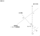
例示的に、進行経路情報に基づき、車載カメラの水平偏角を取得するステップは、
進行経路情報および車載カメラの焦点距離に基づき、車載カメラの水平偏角を取得することを含む。
Illustratively, the step of acquiring the horizontal declination of the vehicle-mounted camera based on the traveling route information is
Includes acquiring the horizontal declination of the vehicle-mounted camera based on the travel path information and the focal length of the vehicle-mounted camera.
例示的に、車載カメラの主光軸が画像にマッピングした画素点から進行経路関数までの距離および車載カメラの焦点距離に基づき、車載カメラの水平偏角を取得する。 Illustratively, the horizontal deviation angle of the vehicle-mounted camera is acquired based on the distance from the pixel point mapped to the image by the main optical axis of the vehicle-mounted camera to the traveling path function and the focal length of the vehicle-mounted camera.
例示的に、車載カメラの主光軸が画像にマッピングした画素点から進行経路関数までの距離D2を取得し、
![]()
![]()
によって車載カメラの水平偏角を取得する。 Acquires the horizontal declination of the in-vehicle camera.
例示的に、図8は本願の実施例が提供する車載カメラの水平偏角推定方法の原理模式図である。図8は車両が路面を走行する平面図である。図8に示すように、ψは車載カメラの水平偏角であり、GACは車両の走行方向であり、tanψ=GH/fである。ここで、GHはカメラ内の撮像素子のサイズであり、GH=CD/PMである。車載カメラの主光軸が画像にマッピングした画素点は点Dであり、CDは車載カメラの主光軸が画像にマッピングした画素点から進行経路関数までの距離D2である。fは車載カメラの焦点距離である。
Illustratively, FIG. 8 is a schematic principle diagram of the horizontal declination estimation method of the vehicle-mounted camera provided in the embodiment of the present application. FIG. 8 is a plan view of the vehicle traveling on the road surface. As shown in FIG. 8, ψ is the horizontal declination of the vehicle-mounted camera, GAC is the traveling direction of the vehicle, and tan ψ = GH / f. Here, GH is the size of the image sensor in the camera, and GH = CD / PM. The pixel point that the main optical axis of the vehicle-mounted camera maps to the image is the point D, and the CD is the distance D2 from the pixel point that the main optical axis of the vehicle-mounted camera maps to the image to the traveling path function. f is the focal length of the vehicle-mounted camera.
例示的に、地平線情報に基づいて車載カメラの姿勢情報を取得するステップは、
地平線の傾斜度情報に基づいて車載カメラの回転角度を特定することを含む。
Illustratively, the step of acquiring the attitude information of the vehicle-mounted camera based on the horizon information is
It includes specifying the rotation angle of the in-vehicle camera based on the inclination information of the horizon.
例示的に、地平線関数は画像において一次関数であり、車載カメラが回転していない時、地平線関数は水平の直線である。車載カメラが回転したら、地平線関数の傾斜度は車載カメラの回転角度を示すことができる。 Illustratively, the horizon function is a linear function in the image, and when the vehicle-mounted camera is not rotating, the horizon function is a horizontal straight line. Once the vehicle-mounted camera has rotated, the tilt of the horizon function can indicate the rotation angle of the vehicle-mounted camera.
本願の実施例の別の一態様はさらに、車載カメラの姿勢推定装置を提供し、図9は本願の実施例が提供する車載カメラの姿勢推定装置の構成模式図である。図9に示すように、車載カメラの姿勢推定装置は、
車載カメラで取得した車両走行路面のビデオストリームに基づいて前記路面の区画線検出を行うための区画線検出モジュール901と、
区画線の検出結果に基づいて前記車両走行路面の地平線情報を取得するための地平線情報取得モジュール902と、
前記地平線情報に基づいて前記車載カメラの姿勢情報を取得するための姿勢情報取得モジュール903と、を含む。
Another aspect of the embodiment of the present application further provides a posture estimation device for the vehicle-mounted camera, and FIG. 9 is a schematic configuration diagram of the posture estimation device for the vehicle-mounted camera provided by the embodiment of the present application. As shown in FIG. 9, the posture estimation device of the in-vehicle camera is
A
The horizon
Includes a posture
本願の実施例が提供する車載カメラの姿勢推定方法および装置は、車載カメラで取得した車両走行路面のビデオストリームに基づいて路面の区画線検出を行うことと、区画線の検出結果に基づいて車両走行路面の地平線情報を取得することと、地平線情報に基づいて車載カメラの姿勢情報を取得することと、を含む。本願の実施例が提供する車載カメラの姿勢推定方法において車載カメラはその位置を固定する必要がなく、かつカメラの姿勢はリアルタイムに取得可能であるため、車載カメラの姿勢推定の正確度を向上させる。 The vehicle-mounted camera attitude estimation method and device provided by the embodiment of the present application perform road surface lane marking detection based on a video stream of the vehicle traveling road surface acquired by the vehicle-mounted camera, and a vehicle based on the lane marking detection result. It includes acquiring the horizon information of the traveling road surface and acquiring the attitude information of the in-vehicle camera based on the horizon information. In the posture estimation method of the vehicle-mounted camera provided by the embodiment of the present application, the position of the vehicle-mounted camera does not need to be fixed, and the posture of the camera can be acquired in real time, so that the accuracy of the posture estimation of the vehicle-mounted camera is improved. ..
いくつかの実施例では、前記路面は構造化道路であり、および/または、前記車載カメラは前記車両のフロントウインドシールドガラスにおける任意の位置に取り付けられる。 In some embodiments, the road surface is a structured road and / or the vehicle-mounted camera is mounted at any position on the front windshield glass of the vehicle.
本願の各実施例における路面は構造化道路である。構造化道路とは一般的に高速道路、都市の幹線道路などの構造化程度が高い道路をいい、このような道路は区画線などの道路標示線を有し、道路の背景環境が比較的単純であり、道路の幾何学的特徴も比較的明瞭である。非構造化道路とは一般的に都市の幹線道路以外の道路、田舎の街道などの構造化程度が低い道路をいい、このような道路は区画線および/または明晰な道路境界がなく、また影および水溜まりなどの影響をも受けており、道路領域および非道路領域は区別しにくい。本願の実施例が提供する技術的解決手段を構造化道路に用いれば、車載カメラの姿勢推定効果が高く、結果が正確である。 The road surface in each embodiment of the present application is a structured road. Structured roads generally refer to highly structured roads such as expressways and arterial roads in cities. Such roads have road marking lines such as lane markings, and the background environment of the road is relatively simple. And the geometric features of the road are also relatively clear. Unstructured roads generally refer to roads other than urban arterial roads, low-structured roads such as rural roads, such roads that have no lane markings and / or clear road boundaries and are shadowed. It is also affected by water pools, etc., and it is difficult to distinguish between road areas and non-road areas. If the technical solution provided by the embodiment of the present application is used for a structured road, the posture estimation effect of the vehicle-mounted camera is high and the result is accurate.
いくつかの実施例では、前記車載カメラの姿勢情報は前記車載カメラの回転角度を含む。 In some embodiments, the posture information of the vehicle-mounted camera includes the rotation angle of the vehicle-mounted camera.
例示的に、図9および図10に示すように、姿勢情報取得モジュール903はさらに、
前記地平線の傾斜度情報に基づいて前記車載カメラの回転角度を特定するように構成された回転角度取得ユニット1001を含んでもよい。
Illustratively, as shown in FIGS. 9 and 10, the posture
The rotation
いくつかの実施例では、前記車載カメラの姿勢情報はさらに前記車載カメラの水平偏角を含む。 In some embodiments, the posture information of the vehicle-mounted camera further includes a horizontal declination of the vehicle-mounted camera.
図9に示すように、車載カメラの姿勢推定装置はさらに、前記地平線情報に基づいて前記車両の進行経路情報を取得するための進行経路情報取得モジュール904を含む。
As shown in FIG. 9, the posture estimation device of the vehicle-mounted camera further includes a traveling route
いくつかの実施例では、図9および図10に示すように、前記姿勢情報取得モジュール903は、
前記進行経路情報に基づき、前記車載カメラの水平偏角を取得するための水平偏角取得ユニット1002を含む。
In some embodiments, as shown in FIGS. 9 and 10, the posture
The horizontal
いくつかの実施例では、前記水平偏角取得ユニット1002は具体的に、前記進行経路情報および前記車載カメラの焦点距離に基づき、前記車載カメラの水平偏角を取得するために用いられる。
In some embodiments, the horizontal
いくつかの実施例では、前記車載カメラの姿勢情報は前記車載カメラのピッチ角を含む。 In some embodiments, the posture information of the vehicle-mounted camera includes the pitch angle of the vehicle-mounted camera.
いくつかの実施例では、図9および図10に示すように、前記姿勢情報取得モジュール903は、
前記地平線情報および前記車載カメラの焦点距離に基づき、前記車載カメラのピッチ角を取得するためのピッチ角取得ユニット1003を含む。
In some embodiments, as shown in FIGS. 9 and 10, the posture
Includes a pitch
いくつかの実施例では、図9に示すように、前記地平線情報取得モジュール902は、
前記区画線の検出結果に基づいて区画線をフィッティングし、少なくとも二つの区画線の区画線情報を得るための区画線情報取得ユニット9021と、
前記少なくとも二つの区画線の区画線情報に基づき、区画線の視覚交点を取得するための交点取得ユニット9022と、
前記区画線の視覚交点に基づき、地平線情報を取得するための地平線情報取得ユニット9023と、を含む。
In some embodiments, as shown in FIG. 9, the horizon
A lane marking
An
Includes a horizon
いくつかの実施例では、前記区画線情報取得ユニット9021は具体的に、前記区画線の検出結果に基づき、区画線に属する区画線画素点を取得し、
前記区画線画素点に基づいて区画線をフィッティングし、少なくとも二つの区画線の区画線情報を得るために用いられる。
In some embodiments, the lane marking
It is used to fit a lane marking based on the lane marking pixel points and obtain lane marking information for at least two lane markings.
いくつかの実施例では、前記地平線情報取得ユニット9023は具体的に、
前記ビデオストリームに含まれる複数フレームの画像の各々における区画線の視覚交点に基づき、交点確率マップを取得し、
前記交点確率マップに基づき、地平線に属する視覚交点を取得し、
取得した地平線に属する視覚交点に基づき、前記地平線情報を取得するために用いられる。
In some embodiments, the horizon
An intersection probability map is obtained based on the visual intersection of the lane markings in each of the plurality of frames of the image included in the video stream.
Based on the intersection probability map, the visual intersections belonging to the horizon are acquired, and
It is used to acquire the horizon information based on the visual intersections belonging to the acquired horizon.
透視の原理によって、区画線は地平線で交差するため、各区画線関数の視覚交点は地平線に落ちる。各区画線関数によって画像における視覚交点の座標を取得できる。例示的に、区画線が曲線である場合、区画線関数が画像画素座標範囲内にある点を区画線関数の視覚交点とする。 Due to the principle of clairvoyance, the lane markings intersect at the horizon, so that the visual intersection of each lane marking function falls to the horizon. The coordinates of the visual intersection in the image can be obtained by each lane marking function. Illustratively, when the lane marking is a curve, the point where the lane marking function is within the image pixel coordinate range is taken as the visual intersection of the lane marking function.
いくつかの実施例では、図9に示すように、車載カメラの姿勢推定装置はさらに、前記ビデオストリームに含まれる複数フレームの画像の各々における少なくとも二つの区画線の視覚交点に基づき、地平線に属する視覚交点を取得し、
前記取得した地平線に属する視覚交点を平均化処理し、前記車載カメラの消失点を取得するための消失点取得モジュール905を含む。
In some embodiments, as shown in FIG. 9, the dashcam attitude estimator further belongs to the horizon based on the visual intersections of at least two lane markings in each of the multi-frame images contained in the video stream. Get the visual intersection,
The vanishing
いくつかの実施例では、図9に示すように、車載カメラの姿勢推定装置はさらに、前記ビデオストリームにおける少なくとも2フレームの画像に基づき、区画線の確率画像を取得し、前記確率画像の各画素点の値が、各画素点が区画線に属する確率を示し、
前記確率画像に基づいて少なくとも二つの区画線の区画線情報を取得し、
前記少なくとも二つの区画線の区画線情報に基づき、前記車載カメラの消失点を取得するための消失点取得モジュール905を含む。
In some embodiments, as shown in FIG. 9, the vehicle-mounted camera attitude estimator further acquires a probabilistic image of the lane markings based on at least two frames of the image in the video stream, and each pixel of the probabilistic image. The value of the point indicates the probability that each pixel point belongs to the lane marking,
Obtaining the lane marking information of at least two lane markings based on the probability image,
A vanishing
例示的に、図9に示すように、車載カメラの姿勢推定装置はさらに、
前記姿勢情報に基づいて前記車載カメラに対してキャリブレーションを行うためのカメラキャリブレーションモジュール906を含む。
Illustratively, as shown in FIG. 9, the posture estimation device of the vehicle-mounted camera further comprises.
Includes a
例示的に、図9に示すように、車載カメラの姿勢推定装置はさらに、
前記姿勢情報に基づいて前記車両の測位情報を特定するための車両測位モジュール907を含む。
Illustratively, as shown in FIG. 9, the posture estimation device of the vehicle-mounted camera further comprises.
A
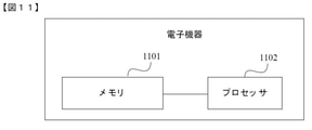
図11は本願の実施例が提供する電子機器の実体のブロック図であり、図11に示すように、該電子機器は、
プログラム命令を記憶するためのメモリ1101と、
前記メモリ内のプログラム命令を呼び出して実行し、上記方法の実施例に記載の方法のステップを実行するためのプロセッサ1102と、を含む。
FIG. 11 is a block diagram of an entity of an electronic device provided by an embodiment of the present application, and as shown in FIG. 11, the electronic device is
Includes a
図12は本願の実施例が提供する車載カメラの姿勢推定システムのアーキテクチャ模式図であり、該システムは車両に用いられ、図12に示すように、該システムは、車両に取り付けられたカメラ1201、およびカメラ1201と接続される上記車載カメラの姿勢推定装置1202を含む。
FIG. 12 is an architectural schematic diagram of an in-vehicle camera attitude estimation system provided by an embodiment of the present application, wherein the system is used in a vehicle, and as shown in FIG. 12, the system is a
本願の実施例はさらに、上記方法の実施例に記載の方法のステップを実行するためのコンピュータプログラムが記憶されている読み取り可能な記憶媒体を提供する。 The embodiments of the present application further provide a readable storage medium in which a computer program for performing the steps of the method described in the embodiment of the above method is stored.
本願の実施例はさらに、コンピュータ命令を含むコンピュータプログラム製品であって、前記コンピュータ命令は機器のプロセッサにおいて運用される時、上記方法の実施例に記載の方法のステップを実現するコンピュータプログラム製品を提供する。 The embodiments of the present application further provide computer program products including computer instructions that, when the computer instructions are operated in a processor of an instrument, implement the steps of the method described in the embodiment of the above method. do.
なお、本願の実施例が提供するいずれかの車載カメラの姿勢推定装置、車載カメラの姿勢推定システム、電子機器内の各部材、モジュールまたはユニットの動作プロセス、設置方式および技術的効果などの説明は、本開示の上記方法の実施例の対応する記載を参照すればよいことを理解すべきであり、紙数に限りがあるので、ここでは詳細な説明を省略する。 In addition, the description of the posture estimation device of any of the vehicle-mounted cameras, the posture estimation system of the vehicle-mounted camera, the operation process of each member, the module or the unit in the electronic device, the installation method, the technical effect, etc. provided by the embodiment of the present application will be described. , It should be understood that the corresponding description of the embodiment of the above method of the present disclosure should be referred to, and since the number of papers is limited, detailed description thereof will be omitted here.
当業者であれば、上記各方法の実施例を実現する全てまたは一部のステップはプログラムによって関連ハードウェアに命令を出すことにより完了できることを理解できる。前記プログラムは、ROM、RAM、磁気ディスクまたは光ディスクなどのプログラムコードを記憶可能である様々な媒体を含むコンピュータ読み取り可能記憶媒体に記憶可能である。該プログラムは実行される時に、上記各方法の実施例を含むステップを実行する。 Those skilled in the art can understand that all or part of the steps to realize the embodiments of each of the above methods can be completed by programmatically instructing the relevant hardware. The program can be stored in a computer-readable storage medium including various media capable of storing the program code such as ROM, RAM, magnetic disk or optical disk. When the program is executed, it performs steps including examples of each of the above methods.
最後に、説明すべきは、以上の各実施例は本願の技術的解決手段を説明するためのものに過ぎず、それを限定するものではなく、前記各実施例を参照しながら本願を詳細に説明したが、当業者であれば、前記各実施例に記載の技術的解決手段に対する修正、またはその一部もしくは全ての技術的特徴に対する置換が可能であることは、当然理解されるものであり、これらの修正または置換は、該当する技術的解決手段の本質を本願の各実施例の技術的解決手段の範囲から逸脱させるものではないということである。 Finally, it should be explained that each of the above embodiments is merely for explaining the technical solution of the present application, and is not limited thereto, and the present application will be described in detail with reference to the respective embodiments. As described above, it is of course understood that those skilled in the art can modify the technical solutions described in each of the above embodiments or replace some or all of the technical features thereof. , These modifications or substitutions do not deviate from the essence of the applicable technical solution within the scope of the technical solution of each embodiment of the present application.
Claims (17)
車載カメラで取得した車両の車両走行路面のビデオストリームに基づいて、前記路面の区画線検出を行うことと、
区画線の検出結果に基づいて、前記車両走行路面の地平線情報を取得することと、
前記地平線情報に基づいて、前記車載カメラの姿勢情報を取得することと
を含み、
前記車載カメラの姿勢情報は、前記車載カメラの水平偏角を含み、
前記地平線情報に基づいて、前記車載カメラの姿勢情報を取得することは、
前記地平線情報および前記車載カメラの消失点に基づいて、前記車両の進行経路情報を取得することと、
前記進行経路情報に基づいて、前記車載カメラの水平偏角を取得することと
を含む、車載カメラの姿勢推定方法。 The posture estimation method for the in-vehicle camera is the posture estimation method for the in-vehicle camera.
Based on the video stream of the vehicle running road surface of the vehicle acquired by the in-vehicle camera, the lane marking detection of the road surface is performed, and
Acquiring the horizon information of the vehicle traveling road surface based on the detection result of the lane marking, and
To acquire the attitude information of the in-vehicle camera based on the horizon information.
Including
The posture information of the vehicle-mounted camera includes the horizontal declination of the vehicle-mounted camera.
Acquiring the attitude information of the in-vehicle camera based on the horizon information is not possible.
Acquiring the traveling route information of the vehicle based on the horizon information and the vanishing point of the vehicle-mounted camera,
To acquire the horizontal declination of the in-vehicle camera based on the traveling route information.
In-vehicle camera posture estimation method including .
前記地平線情報に基づいて、前記車載カメラの姿勢情報を取得することは、地平線の傾斜度情報に基づいて、前記車載カメラの回転角度を特定することを含む、請求項1または請求項2に記載の方法。 The posture information of the vehicle-mounted camera includes the rotation angle of the vehicle-mounted camera.
The first or second aspect of claim 1 or 2, wherein acquiring the attitude information of the vehicle-mounted camera based on the horizon information includes specifying the rotation angle of the vehicle-mounted camera based on the inclination information of the horizon. The method described.
前記区画線の検出結果に基づいて区画線をフィッティングし、少なくとも二つの区画線の区画線情報を得ることと、
前記少なくとも二つの区画線の区画線情報に基づいて、区画線の視覚交点を取得することと、
前記区画線の視覚交点に基づいて、地平線情報を取得することと
を含む、請求項1から6のいずれか一項に記載の方法。 Acquiring the horizon information of the vehicle traveling road surface based on the detection result of the lane marking is not possible .
By fitting the lane markings based on the detection result of the lane markings, the lane marking information of at least two lane markings can be obtained.
Obtaining the visual intersection of the lane markings based on the lane marking information of at least two lane markings,
To acquire horizon information based on the visual intersection of the lane markings
The method according to any one of claims 1 to 6 , comprising the method according to claim 1.
前記区画線の検出結果に基づいて、区画線に属する区画線画素点を取得することと、
前記区画線画素点に基づいて区画線をフィッティングし、少なくとも二つの区画線の区画線情報を得ることと
を含む、請求項7に記載の方法。 Fitting the lane markings based on the detection result of the lane markings and obtaining the lane marking information of at least two lane markings is possible.
Acquiring the lane marking pixel points belonging to the lane marking based on the detection result of the lane marking,
To obtain the lane marking information of at least two lane markings by fitting the lane markings based on the lane marking pixel points.
7. The method of claim 7 .
前記ビデオストリームに含まれる複数フレームの画像の各々における区画線の視覚交点に基づいて、交点確率マップを取得することと、
前記交点確率マップに基づいて、地平線に属する視覚交点を取得することと、
取得した地平線に属する視覚交点に基づいて、前記地平線情報を取得することと
を含む、請求項7または請求項8に記載の方法。 Acquiring horizon information based on the visual intersection of the lane markings
Obtaining an intersection probability map based on the visual intersections of the lane markings in each of the multi-frame images contained in the video stream.
To obtain the visual intersections belonging to the horizon based on the intersection probability map,
To acquire the horizon information based on the visual intersections belonging to the acquired horizon .
7. The method according to claim 7 or 8.
前記ビデオストリームに含まれる複数フレームの画像の各々における少なくとも二つの区画線の視覚交点に基づいて、地平線に属する視覚交点を取得することと、
前記取得した地平線に属する視覚交点を平均化処理し、前記車載カメラの視覚消失点を取得することと
をさらに含む、請求項1に記載の方法。 The method is
Acquiring the visual intersections belonging to the horizon based on the visual intersections of at least two lane markings in each of the multi-frame images contained in the video stream.
To acquire the visual vanishing point of the in-vehicle camera by averaging the visual intersections belonging to the acquired horizon.
The method according to claim 1 , further comprising.
前記ビデオストリームにおける少なくとも2フレームの画像に基づいて、区画線の確率画像を取得することであって、前記確率画像の各画素点の値が、各画素点が区画線に属する確率を示す、ことと、
前記確率画像に基づいて少なくとも二つの区画線の区画線情報を取得することと、
前記少なくとも二つの区画線の区画線情報に基づいて、前記車載カメラの消失点を取得することと
をさらに含む、請求項1に記載の方法。 The method is
Acquiring a probabilistic image of a lane marking based on an image of at least two frames in the video stream, wherein the value of each pixel point in the stochastic image indicates the probability that each pixel point belongs to the lane marking. That and
Acquiring the lane marking information of at least two lane markings based on the probability image,
To acquire the vanishing point of the in-vehicle camera based on the lane marking information of the at least two lane markings .
The method according to claim 1 , further comprising.
前記姿勢情報に基づいて前記車載カメラに対してキャリブレーションを行うこと、および/または、
前記姿勢情報に基づいて前記車両の測位情報を特定すること
をさらに含む、請求項1から11のいずれか一項に記載の方法。 The method is
Calibrate the vehicle-mounted camera based on the attitude information and / or
To specify the positioning information of the vehicle based on the posture information.
The method according to any one of claims 1 to 11 , further comprising.
車載カメラで取得した車両の車両走行路面のビデオストリームに基づいて前記路面の区画線検出を行うための区画線検出モジュールと、
区画線の検出結果に基づいて前記車両走行路面の地平線情報を取得するための地平線情報取得モジュールと、
前記地平線情報に基づいて前記車載カメラの姿勢情報を取得するための姿勢情報取得モジュールと
を含み、
前記車載カメラの姿勢情報は、前記車載カメラの水平偏角を含み、
前記車載カメラの姿勢推定装置は、前記地平線情報および前記車載カメラの消失点に基づいて、前記車両の進行経路情報を取得するための進行経路情報取得モジュールをさらに含み、
前記姿勢情報取得モジュールは、前記進行経路情報に基づいて、前記車載カメラの水平偏角を取得するための水平偏角取得ユニットを含む、車載カメラの姿勢推定装置。 The posture estimation device of the vehicle-mounted camera, and the posture estimation device of the vehicle-mounted camera is
A lane marking module for detecting a lane marking on the road surface based on a video stream of the vehicle traveling road surface of the vehicle acquired by an in-vehicle camera, and a lane marking module.
A horizon information acquisition module for acquiring the horizon information of the vehicle traveling road surface based on the detection result of the lane marking, and
With the attitude information acquisition module for acquiring the attitude information of the in-vehicle camera based on the horizon information
Including
The posture information of the vehicle-mounted camera includes the horizontal declination of the vehicle-mounted camera.
The vehicle-mounted camera attitude estimation device further includes a traveling route information acquisition module for acquiring traveling route information of the vehicle based on the horizon information and the vanishing point of the vehicle-mounted camera.
The posture information acquisition module is a posture estimation device for an in-vehicle camera, which includes a horizontal declination acquisition unit for acquiring the horizontal declination of the in-vehicle camera based on the traveling path information .
前記メモリ内のプログラム命令を呼び出して実行し、請求項1から12のいずれか一項に記載の方法を実行するためのプロセッサと
を含む電子機器。 Memory for storing program instructions and
With a processor for calling and executing the program instruction in the memory and executing the method according to any one of claims 1 to 12 .
Electronic devices including.
前記車両に取り付けられたカメラと、前記カメラと通信的に接続されている請求項13に記載の車載カメラの姿勢推定装置とを含む車載カメラの姿勢推定システム。 It is a posture estimation system for in -vehicle cameras used in vehicles.
A posture estimation system for an in-vehicle camera including a camera attached to the vehicle and an attitude estimation device for the in-vehicle camera according to claim 13 , which is communicatively connected to the camera.
前記コンピュータ命令は、機器のプロセッサによって実行されると、請求項1から12のいずれか一項に記載の車載カメラの姿勢推定方法を実現する、コンピュータプログラム。
A computer program that contains computer instructions
A computer program that , when executed by a processor of an apparatus, realizes the posture estimation method for an in-vehicle camera according to any one of claims 1 to 12 .
Applications Claiming Priority (3)
| Application Number | Priority Date | Filing Date | Title |
|---|---|---|---|
| CN201810973920.XA CN110858405A (en) | 2018-08-24 | 2018-08-24 | Attitude estimation method, device and system of vehicle-mounted camera and electronic equipment |
| CN201810973920.X | 2018-08-24 | ||
| PCT/CN2019/093911 WO2020038118A1 (en) | 2018-08-24 | 2019-06-28 | Method, apparatus and system for estimating pose of vehicle-mounted camera, and electronic device |
Publications (3)
| Publication Number | Publication Date |
|---|---|
| JP2020533667A JP2020533667A (en) | 2020-11-19 |
| JP2020533667A5 JP2020533667A5 (en) | 2021-08-12 |
| JP6995188B2 true JP6995188B2 (en) | 2022-01-14 |
Family
ID=69592397
Family Applications (1)
| Application Number | Title | Priority Date | Filing Date |
|---|---|---|---|
| JP2020510614A Active JP6995188B2 (en) | 2018-08-24 | 2019-06-28 | In-vehicle camera attitude estimation methods, devices and systems, and electronic devices |
Country Status (5)
| Country | Link |
|---|---|
| US (1) | US11205284B2 (en) |
| JP (1) | JP6995188B2 (en) |
| CN (1) | CN110858405A (en) |
| SG (1) | SG11202000641UA (en) |
| WO (1) | WO2020038118A1 (en) |
Families Citing this family (11)
| Publication number | Priority date | Publication date | Assignee | Title |
|---|---|---|---|---|
| US10816354B2 (en) | 2017-08-22 | 2020-10-27 | Tusimple, Inc. | Verification module system and method for motion-based lane detection with multiple sensors |
| US11009356B2 (en) | 2018-02-14 | 2021-05-18 | Tusimple, Inc. | Lane marking localization and fusion |
| US11009365B2 (en) | 2018-02-14 | 2021-05-18 | Tusimple, Inc. | Lane marking localization |
| EP3893150A1 (en) * | 2020-04-09 | 2021-10-13 | Tusimple, Inc. | Camera pose estimation techniques |
| CN113490967A (en) * | 2020-09-22 | 2021-10-08 | 深圳市锐明技术股份有限公司 | Camera calibration method and device and electronic equipment |
| CN112384952A (en) * | 2020-09-22 | 2021-02-19 | 深圳市锐明技术股份有限公司 | Camera calibration method and device and electronic equipment |
| CN112597965A (en) * | 2021-01-05 | 2021-04-02 | 株洲中车时代电气股份有限公司 | Driving behavior recognition method and device and computer readable storage medium |
| CN112907678B (en) * | 2021-01-25 | 2022-05-13 | 深圳佑驾创新科技有限公司 | Vehicle-mounted camera external parameter attitude dynamic estimation method and device and computer equipment |
| US11875580B2 (en) * | 2021-10-04 | 2024-01-16 | Motive Technologies, Inc. | Camera initialization for lane detection and distance estimation using single-view geometry |
| CN114494439B (en) * | 2022-01-25 | 2023-08-15 | 襄阳达安汽车检测中心有限公司 | Camera pose calibration method, device, equipment and medium in HIL simulation test |
| CN117252880B (en) * | 2023-11-17 | 2024-01-16 | 宝德华南(深圳)热能系统有限公司 | Adas comprehensive evaluation system of new energy automobile |
Citations (3)
| Publication number | Priority date | Publication date | Assignee | Title |
|---|---|---|---|---|
| JP2007034989A (en) | 2005-07-29 | 2007-02-08 | Nissan Motor Co Ltd | Slippage detection method and slippage correction method of imaging device, and imaging device |
| JP2010537331A (en) | 2007-08-31 | 2010-12-02 | ヴァレオ・シャルター・ウント・ゼンゾーレン・ゲーエムベーハー | Video image online calibration method and system |
| JP2011022995A (en) | 2009-06-16 | 2011-02-03 | Nippon Soken Inc | Vanishing point estimation device and program |
Family Cites Families (16)
| Publication number | Priority date | Publication date | Assignee | Title |
|---|---|---|---|---|
| US8487991B2 (en) * | 2008-04-24 | 2013-07-16 | GM Global Technology Operations LLC | Clear path detection using a vanishing point |
| US9129161B2 (en) * | 2013-05-31 | 2015-09-08 | Toyota Jidosha Kabushiki Kaisha | Computationally efficient scene classification |
| JP5906272B2 (en) * | 2014-03-28 | 2016-04-20 | 富士重工業株式会社 | Stereo image processing apparatus for vehicle |
| GB201410612D0 (en) * | 2014-06-13 | 2014-07-30 | Tomtom Int Bv | Methods and systems for generating route data |
| US10694175B2 (en) * | 2015-12-28 | 2020-06-23 | Intel Corporation | Real-time automatic vehicle camera calibration |
| JP6614042B2 (en) | 2016-06-15 | 2019-12-04 | 株式会社Jvcケンウッド | Posture change determination device, overhead view video generation device, overhead view video generation system, posture change determination method, and program |
| CN106204574B (en) | 2016-07-07 | 2018-12-21 | 兰州理工大学 | Camera pose self-calibrating method based on objective plane motion feature |
| KR102538592B1 (en) * | 2016-08-31 | 2023-05-31 | 현대모비스 주식회사 | Apparatus for generating top-view image and method thereof |
| CN106679633B (en) * | 2016-12-07 | 2019-06-04 | 东华大学 | A kind of vehicle-mounted distance-finding system base and method |
| CN107330940A (en) * | 2017-01-25 | 2017-11-07 | 问众智能信息科技(北京)有限公司 | The method and apparatus that in-vehicle camera posture is estimated automatically |
| CN106875448B (en) * | 2017-02-16 | 2019-07-23 | 武汉极目智能技术有限公司 | A kind of vehicle-mounted monocular camera external parameter self-calibrating method |
| CN107145825A (en) * | 2017-03-31 | 2017-09-08 | 纵目科技(上海)股份有限公司 | Ground level fitting, camera calibration method and system, car-mounted terminal |
| CN107133985B (en) * | 2017-04-20 | 2020-05-12 | 常州智行科技有限公司 | Automatic calibration method for vehicle-mounted camera based on lane line vanishing point |
| CN108229386B (en) * | 2017-12-29 | 2021-12-14 | 百度在线网络技术(北京)有限公司 | Method, apparatus, and medium for detecting lane line |
| CN108875603B (en) * | 2018-05-31 | 2021-06-04 | 上海商汤智能科技有限公司 | Intelligent driving control method and device based on lane line and electronic equipment |
| CN108898638A (en) * | 2018-06-27 | 2018-11-27 | 江苏大学 | A kind of on-line automatic scaling method of vehicle-mounted camera |
-
2018
- 2018-08-24 CN CN201810973920.XA patent/CN110858405A/en active Pending
-
2019
- 2019-06-28 JP JP2020510614A patent/JP6995188B2/en active Active
- 2019-06-28 SG SG11202000641UA patent/SG11202000641UA/en unknown
- 2019-06-28 WO PCT/CN2019/093911 patent/WO2020038118A1/en active Application Filing
-
2020
- 2020-01-21 US US16/748,785 patent/US11205284B2/en active Active
Patent Citations (3)
| Publication number | Priority date | Publication date | Assignee | Title |
|---|---|---|---|---|
| JP2007034989A (en) | 2005-07-29 | 2007-02-08 | Nissan Motor Co Ltd | Slippage detection method and slippage correction method of imaging device, and imaging device |
| JP2010537331A (en) | 2007-08-31 | 2010-12-02 | ヴァレオ・シャルター・ウント・ゼンゾーレン・ゲーエムベーハー | Video image online calibration method and system |
| JP2011022995A (en) | 2009-06-16 | 2011-02-03 | Nippon Soken Inc | Vanishing point estimation device and program |
Also Published As
| Publication number | Publication date |
|---|---|
| US11205284B2 (en) | 2021-12-21 |
| WO2020038118A1 (en) | 2020-02-27 |
| US20200160561A1 (en) | 2020-05-21 |
| SG11202000641UA (en) | 2020-03-30 |
| JP2020533667A (en) | 2020-11-19 |
| CN110858405A (en) | 2020-03-03 |
Similar Documents
| Publication | Publication Date | Title |
|---|---|---|
| JP6995188B2 (en) | In-vehicle camera attitude estimation methods, devices and systems, and electronic devices | |
| US11763571B2 (en) | Monocular cued detection of three-dimensional structures from depth images | |
| JP6844043B2 (en) | Visual positioning methods, devices, electronics and systems | |
| JP5375958B2 (en) | Image processing apparatus and image processing method | |
| JP4801821B2 (en) | Road shape estimation device | |
| CN108629292B (en) | Curved lane line detection method and device and terminal | |
| JP5714940B2 (en) | Moving body position measuring device | |
| JP2020533667A5 (en) | ||
| JP6756101B2 (en) | Object recognition device | |
| CN111213153A (en) | Target object motion state detection method, device and storage medium | |
| CN111738033B (en) | Vehicle driving information determination method and device based on plane segmentation and vehicle-mounted terminal | |
| JP7259309B2 (en) | Image processing device and image processing method | |
| CN115187940A (en) | Image detection method and device for vehicle | |
| JP2014106739A (en) | In-vehicle image processing device | |
| JP2012215442A (en) | Own position determination system, own position determination program, own position determination method | |
| CN113902047B (en) | Image element matching method, device, equipment and storage medium | |
| CN114037977B (en) | Road vanishing point detection method, device, equipment and storage medium | |
| CN116524454A (en) | Object tracking device, object tracking method, and storage medium | |
| US11477371B2 (en) | Partial image generating device, storage medium storing computer program for partial image generation and partial image generating method | |
| JP5903901B2 (en) | Vehicle position calculation device | |
| WO2022133986A1 (en) | Accuracy estimation method and system | |
| CN113345087A (en) | Monocular vision-based earth surface model fitting method and device | |
| JP2019027965A (en) | Correction device, method for correction, and program | |
| CN113147746A (en) | Method and device for detecting ramp parking space | |
| CN115943287A (en) | Vehicle attitude estimation system and vehicle attitude estimation method |
Legal Events
| Date | Code | Title | Description |
|---|---|---|---|
| A521 | Request for written amendment filed |
Free format text: JAPANESE INTERMEDIATE CODE: A523 Effective date: 20200220 |
|
| A621 | Written request for application examination |
Free format text: JAPANESE INTERMEDIATE CODE: A621 Effective date: 20200220 |
|
| A977 | Report on retrieval |
Free format text: JAPANESE INTERMEDIATE CODE: A971007 Effective date: 20210330 |
|
| A131 | Notification of reasons for refusal |
Free format text: JAPANESE INTERMEDIATE CODE: A131 Effective date: 20210401 |
|
| A524 | Written submission of copy of amendment under article 19 pct |
Free format text: JAPANESE INTERMEDIATE CODE: A524 Effective date: 20210701 |
|
| TRDD | Decision of grant or rejection written | ||
| A01 | Written decision to grant a patent or to grant a registration (utility model) |
Free format text: JAPANESE INTERMEDIATE CODE: A01 Effective date: 20211125 |
|
| A61 | First payment of annual fees (during grant procedure) |
Free format text: JAPANESE INTERMEDIATE CODE: A61 Effective date: 20211214 |
|
| R150 | Certificate of patent or registration of utility model |
Ref document number: 6995188 Country of ref document: JP Free format text: JAPANESE INTERMEDIATE CODE: R150 |
|
| R250 | Receipt of annual fees |
Free format text: JAPANESE INTERMEDIATE CODE: R250 |