JP6994780B2 - Hydrogen water generator - Google Patents
Hydrogen water generator Download PDFInfo
- Publication number
- JP6994780B2 JP6994780B2 JP2020090527A JP2020090527A JP6994780B2 JP 6994780 B2 JP6994780 B2 JP 6994780B2 JP 2020090527 A JP2020090527 A JP 2020090527A JP 2020090527 A JP2020090527 A JP 2020090527A JP 6994780 B2 JP6994780 B2 JP 6994780B2
- Authority
- JP
- Japan
- Prior art keywords
- water
- electrode plates
- electrolytic cell
- hydrogen
- discharge port
- Prior art date
- Legal status (The legal status is an assumption and is not a legal conclusion. Google has not performed a legal analysis and makes no representation as to the accuracy of the status listed.)
- Active
Links
- XLYOFNOQVPJJNP-UHFFFAOYSA-N water Substances O XLYOFNOQVPJJNP-UHFFFAOYSA-N 0.000 title claims description 239
- 239000001257 hydrogen Substances 0.000 title claims description 154
- 229910052739 hydrogen Inorganic materials 0.000 title claims description 154
- UFHFLCQGNIYNRP-UHFFFAOYSA-N Hydrogen Chemical compound [H][H] UFHFLCQGNIYNRP-UHFFFAOYSA-N 0.000 title claims description 146
- 238000005868 electrolysis reaction Methods 0.000 claims description 70
- 239000007864 aqueous solution Substances 0.000 claims description 57
- 238000002347 injection Methods 0.000 claims description 33
- 239000007924 injection Substances 0.000 claims description 33
- 230000005611 electricity Effects 0.000 claims description 14
- 238000003860 storage Methods 0.000 description 51
- 230000004087 circulation Effects 0.000 description 23
- 239000002245 particle Substances 0.000 description 19
- 239000002101 nanobubble Substances 0.000 description 14
- 239000007789 gas Substances 0.000 description 12
- 239000000126 substance Substances 0.000 description 12
- ZAMOUSCENKQFHK-UHFFFAOYSA-N Chlorine atom Chemical compound [Cl] ZAMOUSCENKQFHK-UHFFFAOYSA-N 0.000 description 9
- QVGXLLKOCUKJST-UHFFFAOYSA-N atomic oxygen Chemical compound [O] QVGXLLKOCUKJST-UHFFFAOYSA-N 0.000 description 9
- 239000000460 chlorine Substances 0.000 description 9
- 229910052801 chlorine Inorganic materials 0.000 description 9
- 150000002431 hydrogen Chemical class 0.000 description 9
- 239000001301 oxygen Substances 0.000 description 9
- 229910052760 oxygen Inorganic materials 0.000 description 9
- 230000000694 effects Effects 0.000 description 6
- 229910001220 stainless steel Inorganic materials 0.000 description 6
- 239000010935 stainless steel Substances 0.000 description 6
- 230000008859 change Effects 0.000 description 5
- 244000144972 livestock Species 0.000 description 5
- 239000008399 tap water Substances 0.000 description 5
- 235000020679 tap water Nutrition 0.000 description 5
- 241000607479 Yersinia pestis Species 0.000 description 4
- BASFCYQUMIYNBI-UHFFFAOYSA-N platinum Chemical compound [Pt] BASFCYQUMIYNBI-UHFFFAOYSA-N 0.000 description 4
- 238000005507 spraying Methods 0.000 description 4
- 230000007797 corrosion Effects 0.000 description 3
- 238000005260 corrosion Methods 0.000 description 3
- 230000007423 decrease Effects 0.000 description 3
- 230000003247 decreasing effect Effects 0.000 description 3
- 235000013601 eggs Nutrition 0.000 description 3
- 238000001914 filtration Methods 0.000 description 3
- 238000003973 irrigation Methods 0.000 description 3
- 230000002262 irrigation Effects 0.000 description 3
- 239000007788 liquid Substances 0.000 description 3
- 239000000463 material Substances 0.000 description 3
- 239000002105 nanoparticle Substances 0.000 description 3
- 150000003839 salts Chemical class 0.000 description 3
- 230000001954 sterilising effect Effects 0.000 description 3
- 238000004659 sterilization and disinfection Methods 0.000 description 3
- OKTJSMMVPCPJKN-UHFFFAOYSA-N Carbon Chemical compound [C] OKTJSMMVPCPJKN-UHFFFAOYSA-N 0.000 description 2
- FAPWRFPIFSIZLT-UHFFFAOYSA-M Sodium chloride Chemical compound [Na+].[Cl-] FAPWRFPIFSIZLT-UHFFFAOYSA-M 0.000 description 2
- RTAQQCXQSZGOHL-UHFFFAOYSA-N Titanium Chemical compound [Ti] RTAQQCXQSZGOHL-UHFFFAOYSA-N 0.000 description 2
- 230000005540 biological transmission Effects 0.000 description 2
- 229910052799 carbon Inorganic materials 0.000 description 2
- 238000006243 chemical reaction Methods 0.000 description 2
- 238000010586 diagram Methods 0.000 description 2
- 210000003608 fece Anatomy 0.000 description 2
- 239000003337 fertilizer Substances 0.000 description 2
- PCHJSUWPFVWCPO-UHFFFAOYSA-N gold Chemical compound [Au] PCHJSUWPFVWCPO-UHFFFAOYSA-N 0.000 description 2
- 229910052737 gold Inorganic materials 0.000 description 2
- 239000010931 gold Substances 0.000 description 2
- 230000012447 hatching Effects 0.000 description 2
- 239000003501 hydroponics Substances 0.000 description 2
- QWPPOHNGKGFGJK-UHFFFAOYSA-N hypochlorous acid Chemical compound ClO QWPPOHNGKGFGJK-UHFFFAOYSA-N 0.000 description 2
- 230000002401 inhibitory effect Effects 0.000 description 2
- 230000014759 maintenance of location Effects 0.000 description 2
- 238000004519 manufacturing process Methods 0.000 description 2
- 229910052751 metal Inorganic materials 0.000 description 2
- 239000002184 metal Substances 0.000 description 2
- 239000007769 metal material Substances 0.000 description 2
- 239000008239 natural water Substances 0.000 description 2
- 230000003647 oxidation Effects 0.000 description 2
- 238000007254 oxidation reaction Methods 0.000 description 2
- 230000008635 plant growth Effects 0.000 description 2
- 229910052697 platinum Inorganic materials 0.000 description 2
- 238000006722 reduction reaction Methods 0.000 description 2
- 229920003002 synthetic resin Polymers 0.000 description 2
- 239000000057 synthetic resin Substances 0.000 description 2
- 229910052719 titanium Inorganic materials 0.000 description 2
- 239000010936 titanium Substances 0.000 description 2
- 241000238876 Acari Species 0.000 description 1
- 241000283690 Bos taurus Species 0.000 description 1
- OYPRJOBELJOOCE-UHFFFAOYSA-N Calcium Chemical compound [Ca] OYPRJOBELJOOCE-UHFFFAOYSA-N 0.000 description 1
- RYGMFSIKBFXOCR-UHFFFAOYSA-N Copper Chemical compound [Cu] RYGMFSIKBFXOCR-UHFFFAOYSA-N 0.000 description 1
- 241000287828 Gallus gallus Species 0.000 description 1
- FYYHWMGAXLPEAU-UHFFFAOYSA-N Magnesium Chemical compound [Mg] FYYHWMGAXLPEAU-UHFFFAOYSA-N 0.000 description 1
- 231100000674 Phytotoxicity Toxicity 0.000 description 1
- 241000282887 Suidae Species 0.000 description 1
- 241001414989 Thysanoptera Species 0.000 description 1
- 238000010521 absorption reaction Methods 0.000 description 1
- 239000000654 additive Substances 0.000 description 1
- 229910052782 aluminium Inorganic materials 0.000 description 1
- XAGFODPZIPBFFR-UHFFFAOYSA-N aluminium Chemical compound [Al] XAGFODPZIPBFFR-UHFFFAOYSA-N 0.000 description 1
- 230000000844 anti-bacterial effect Effects 0.000 description 1
- 230000001174 ascending effect Effects 0.000 description 1
- 230000015572 biosynthetic process Effects 0.000 description 1
- 238000009395 breeding Methods 0.000 description 1
- 230000001488 breeding effect Effects 0.000 description 1
- 230000003139 buffering effect Effects 0.000 description 1
- 239000011575 calcium Substances 0.000 description 1
- 229910052791 calcium Inorganic materials 0.000 description 1
- 235000013330 chicken meat Nutrition 0.000 description 1
- 229910052802 copper Inorganic materials 0.000 description 1
- 239000010949 copper Substances 0.000 description 1
- 238000000354 decomposition reaction Methods 0.000 description 1
- 230000029087 digestion Effects 0.000 description 1
- 238000007599 discharging Methods 0.000 description 1
- 201000010099 disease Diseases 0.000 description 1
- 208000037265 diseases, disorders, signs and symptoms Diseases 0.000 description 1
- 235000020188 drinking water Nutrition 0.000 description 1
- 239000003651 drinking water Substances 0.000 description 1
- 239000000428 dust Substances 0.000 description 1
- -1 etc.) Substances 0.000 description 1
- 238000010413 gardening Methods 0.000 description 1
- 230000005484 gravity Effects 0.000 description 1
- 230000036541 health Effects 0.000 description 1
- 150000002484 inorganic compounds Chemical class 0.000 description 1
- 229910010272 inorganic material Inorganic materials 0.000 description 1
- 230000007774 longterm Effects 0.000 description 1
- 239000011777 magnesium Substances 0.000 description 1
- 229910052749 magnesium Inorganic materials 0.000 description 1
- 238000012423 maintenance Methods 0.000 description 1
- 239000000575 pesticide Substances 0.000 description 1
- 238000007747 plating Methods 0.000 description 1
- 238000002360 preparation method Methods 0.000 description 1
- 238000004080 punching Methods 0.000 description 1
- 230000009467 reduction Effects 0.000 description 1
- 210000004189 reticular formation Anatomy 0.000 description 1
- 229920006395 saturated elastomer Polymers 0.000 description 1
- 230000035939 shock Effects 0.000 description 1
- 239000011780 sodium chloride Substances 0.000 description 1
- 239000002689 soil Substances 0.000 description 1
- 230000007704 transition Effects 0.000 description 1
- 235000013311 vegetables Nutrition 0.000 description 1
- 235000020681 well water Nutrition 0.000 description 1
- 239000002349 well water Substances 0.000 description 1
Images


Landscapes
- Water Treatment By Electricity Or Magnetism (AREA)
Description
本発明は、水の電気分解により水素水を生成する水素水生成装置に関する。 The present invention relates to a hydrogen water generator that produces hydrogen water by electrolysis of water.
電解槽の水中に電極を配置し、電気分解により水素を含有する水素水を生成する装置が知られている。例えば特許文献1に記載の電解水生成装置は、水を電気分解する電解部と、この電解部に電力を供給する電源部とを備え、電解部は互いに並列に接続された電解槽を含むことから、野菜栽培等のように大量の電解還元水が必要な場合であっても、汎用の電解槽を複数備えた電解水生成装置を利用して安価に大量の電解還元水を生成できるというものである。
A device is known in which an electrode is placed in the water of an electrolytic cell and hydrogen water containing hydrogen is generated by electrolysis. For example, the electrolytic water generator described in
また、文献2に記載の水素水製造装置は、水を電気分解して水素と酸素とを発生させる水電気分解装置と、電気分解により生成された電気分解水中に水素及び酸素のナノバブルを発生させるナノバブル発生装置と、を備え、このナノバブル発生装置は、電気分解水を貯留するとともに密閉された耐圧容器で形成された液体貯留槽と、電気分解により発生した気体を液体貯留槽内の電気分解水中に高圧で放出する気体放出手段等、を備えるというものである。
Further, the hydrogen water production apparatus described in
さて、上記特許文献1の電解水生成装置は、電解部に複数(ここでは3つ)の電解槽を設けて、大量の電解還元水を生成することとしているが、より多くの電解水を得るためにはさらに電解槽の数を増やす必要があり、このため装置が大型化し、また場所の確保などで拡張性、汎用性等に欠けるという問題がある。
また、特許文献2の水素水製造装置は、水電気分解装置とナノバブル発生装置とを備え、また耐圧容器等を用いること等から装置が複雑化し、また経済性にも欠けるという問題がある。
By the way, in the electrolyzed water generator of
Further, the hydrogen water production apparatus of
本発明は上記問題点に鑑みてなされたものであり、効率的に大量の水素水を生成し、また機能性、経済性にも優れた水素水生成装置を提供することを目的とする。 The present invention has been made in view of the above problems, and an object of the present invention is to provide a hydrogen water generator which efficiently generates a large amount of hydrogen water and is also excellent in functionality and economy.
以上の技術的課題を解決するため、本発明に係る水素水生成装置は図1等に示すように、網状の電極板6と、上記電極板6を、所定間隔をおいて3枚以上互いに向い合せに配置し、これら電極板6の並びの一方側に水の注入口30を、また他方側に水の排出口32をそれぞれ設けた電解槽4と、上記各電極板6に電圧を印加し、隣り合う電極板6間及び他の電極板6を介在させた電極板6間に電流を流して電気分解を行わせる電源回路部11と、を有し、上記電解槽4の上記注入口30から水を注入し、この水を上記注入口30側から上記排出口32側に移動させ、この移動する水を上記電極板6により電気分解し、水中に水素を含有する水溶液を生成し、これを上記排出口32から排出する構成である。
In order to solve the above technical problems, as shown in FIG. 1 and the like, the hydrogen water generator according to the present invention has three or more mesh-
本発明に係る水素水生成装置は、上記電極板6の数を、4枚以上16枚以下の範囲とした構成である。
The hydrogen water generator according to the present invention has a configuration in which the number of the
本発明に係る水素水生成装置の上記電源回路部11は、上記電極板6の内の特定の電極板6間に交流電圧を印加し、且つ当該特定の電極板6以外の電極板6には直流電圧を印加し、電気分解を行わせる構成である。
The power
本発明に係る水素水生成装置の上記電源回路部11は、上記電極板6の内、他の電極板6を介在させた特定の電極板6間に交流電圧を印加し、且つ当該特定の電極板6以外の電極板6には直流電圧を印加し、この直流電圧の極性を定期的に切り替え、電気分解を行わせる構成である。
The power
本発明に係る水素水生成装置の上記電源回路部11は、上記電極板6を、連続する4枚を一組とし、各一組の上記電極板6の内、他の電極板6を介在させた特定の電極板6間に交流電圧を印加し、且つ当該特定の電極板6以外の電極板6(上記他の電極板6を含む)には直流電圧を印加し、電気分解を行わせる構成である。
ここで、例えば、低い直流電圧(グラウンド)を電極板6に印加した場合、この(全ての)電極板6に向けて、交流電圧の高い時点の電位(V+)が印加された特定の電極板6から電流(直流)を流すようにする。
また、例えば直流電圧の極性を切り替え、高い直流電圧(V+)を電極板6に印加した場合、この(全ての)電極板から、交流電圧の低い電位(グラウンド)が印加された時点の特定の電極板に向けて電流(直流)を流すようにする。
In the power
Here, for example, when a low DC voltage (ground) is applied to the
Further, for example, when the polarity of the DC voltage is switched and a high DC voltage (V +) is applied to the
本発明に係る水素水生成装置は、上記注入口30を上記電解槽4の下部近傍に設けて水を注入する一方、上記排出口32を上記電解槽4の上部近傍に設けて、上記注入された水を注入口30から排出口32方向へ移動させるとともに、下方から上方へと移動させ、この移動する水を上記各電極板6により電気分解し、上記排出口32から排出する構成である。
In the hydrogen water generator according to the present invention, the
本発明に係る水素水生成装置は、上記排出口32と連通する切替弁を設け、上記排出口32から排出された水溶液の濾過器12を通過する流路と、この濾過器12を通過しない流路とを切り換え可能とした構成である。
The hydrogen water generator according to the present invention is provided with a switching valve that communicates with the
本発明に係る水素水生成装置は、上記電解槽4の排出口32から排出された水溶液を溜める貯留タンク16と、この貯留タンク16内の水溶液を吸引し、これを上記電解槽4へ流通させるポンプ14と、を有し、上記ポンプ14により、上記電解槽4で電気分解された水溶液を上記貯留タンク16へ供給する一方、上記貯留タンク16内の水溶液を吸引して上記電解槽4に送り、これを再度電気分解する循環流路62を駆動させ、水溶液中の水素濃度を高める構成である。
ここで、水素水生成装置の運転状況を管理する制御部10を設け、この制御部10に上記循環流路62の循環時間として、ポンプ14を稼働させて循環流路を流通させる時間を登録することで、この循環時間により水素濃度の調節を行うことができる。
The hydrogen water generator according to the present invention sucks the
Here, a
本発明に係る水素水生成装置によれば、網状の電極板を3枚以上互いに向い合せに配置し、一方側に注入口を他方側に排出口をそれぞれ設けた電解槽、及び隣り合う電極板間等に電流を流して電気分解を行わせる電源回路部を有し、電解槽を移動する水を電極板により電気分解し、水素を含有する水溶液を生成する構成を採用したから、効率的に水素を含有する水溶液(水素水)を大量に得ることができ、また装置の小型化が図れ、経済的にも優れるという効果を奏する。 According to the hydrogen water generator according to the present invention, three or more reticulated electrode plates are arranged facing each other, an electrolytic tank having an inlet on one side and an outlet on the other side, and adjacent electrode plates. It has a power supply circuit unit that allows current to flow between them to perform electrolysis, and adopts a configuration that electrolyzes the water moving in the electrolytic tank with an electrode plate to generate an aqueous solution containing hydrogen, so it is efficient. A large amount of hydrogen-containing aqueous solution (hydrogen water) can be obtained, the device can be miniaturized, and it is economically excellent.
本発明に係る水素水生成装置によれば、電源回路部は、特定の電極板間に交流電圧を、これ以外の電極板には直流電圧を印加し、電気分解を行わせる構成を採用したから、電極板間で効率的に電気分解が行なえて、電解槽等の装置の小型化が図れ、機能的にも優れた水素水生成装置が得られるという効果がある。 According to the hydrogen water generator according to the present invention, the power supply circuit unit adopts a configuration in which an AC voltage is applied between specific electrode plates and a DC voltage is applied to other electrode plates to perform electrolysis. There is an effect that electrolysis can be efficiently performed between the electrode plates, the device such as an electrolytic tank can be miniaturized, and a functionally excellent hydrogen water generation device can be obtained.
本発明に係る水素水生成装置によれば、電源回路部は、他の電極板を介在させた特定の電極板間に交流電圧を、これ以外の電極板には直流電圧を印加し、この直流電圧の極性を定期的に切り替え、電気分解を行わせる構成としたから、全ての電極板間で効率的に電気分解が行えることから、電解槽等の装置の小型化が図れ、また電極板の付着物(無機物質等)も除去され、機能的にも優れた水素水生成装置が得られるという効果がある。 According to the hydrogen water generator according to the present invention, the power supply circuit unit applies an AC voltage between specific electrode plates interposed with other electrode plates and a DC voltage to the other electrode plates, and this DC is applied. Since the polarity of the voltage is switched periodically and electrolysis is performed, the electrolysis can be efficiently performed between all the electrode plates, so that the equipment such as the electrolytic tank can be miniaturized and the electrode plate can be used. It also has the effect of removing deposits (inorganic substances, etc.) and obtaining a functionally superior hydrogen water generator.
本発明に係る水素水生成装置によれば、4枚一組の電極板の内、他の電極板を介在させた特定の電極板6間に交流電圧を、これ以外の電極板には直流電圧を印加し、電気分解を行わせる構成としたから、隣り合う全ての電極板間で電流(直流)を流すことができ、効率よく電気分解が行える。また4枚一組の組み合わせでは、電極板間で交流電圧の印加と直流電圧の印加とが交互となり、他の組の電極板6との組同士間でも電流を流して電気分解を行うことが出来て効率がよい。
According to the hydrogen water generator according to the present invention, an AC voltage is applied between
本発明に係る水素水生成装置によれば、注入口を電解槽の下部近傍に設ける一方、排出口を電解槽の上部近傍に設け、注入され下方から上方へ移動する水を各電極板により電気分解する構成を採用したから、電解槽内の水の移動が淀みなく満遍に行えて良好に電気分解が行なえ、また水の滞留も防止できるという効果がある。 According to the hydrogen water generator according to the present invention, the injection port is provided near the lower part of the electrolytic cell, while the discharge port is provided near the upper part of the electrolytic cell, and the water that is injected and moves from the lower side to the upper side is electrified by each electrode plate. Since the structure that decomposes is adopted, the water in the electrolytic cell can be moved evenly without stagnation, the electrolysis can be performed well, and the retention of water can be prevented.
本発明に係る水素水生成装置によれば、排出口と連通する切替弁を設け、濾過器を通過する流路と通過しない流路とを切り替え可能としたから、必要に応じ選択的に濾過器による塩素系物質等の除去が行えるという効果がある。 According to the hydrogen water generator according to the present invention, a switching valve that communicates with the discharge port is provided so that the flow path that passes through the filter and the flow path that does not pass through can be switched. It has the effect of being able to remove chlorine-based substances and the like.
本発明に係る水素水生成装置によれば、ポンプにより、電解槽で電気分解された水溶液を貯留タンクへ供給する一方、貯留タンク内の水溶液を吸引して電解槽に送り、これを再度電気分解する循環流路を駆動させる構成を採用したから、容易に高濃度の水溶液(水素水)を得ることができ、また水溶液中の水素濃度の管理が容易であるという効果がある。 According to the hydrogen water generator according to the present invention, the aqueous solution electrolyzed in the electrolytic tank is supplied to the storage tank by a pump, while the aqueous solution in the storage tank is sucked and sent to the electrolytic tank, which is electrolyzed again. Since the configuration for driving the circulation flow path is adopted, it is possible to easily obtain a high-concentration aqueous solution (hydrogen water), and there is an effect that the hydrogen concentration in the aqueous solution can be easily controlled.
以下、本発明に係る水素水生成装置の実施の形態を説明する。
図1,2は、実施の形態に係る水素水生成装置2を示すものである。
この水素水生成装置2は、電解槽4、この電解槽4内に配置され水を電気分解する電極板6、制御盤8、濾過器12、ポンプ14、及び貯留タンク16等を有する。
また、図3に示すように制御盤8には、操作パネル9が設けられ、装置の制御及び運転管理等を行う制御部10、及び上記電極板6に電気を供給する電源回路部11等が内蔵されている。
Hereinafter, embodiments of the hydrogen water generator according to the present invention will be described.
FIGS. 1 and 2 show the hydrogen
The hydrogen
Further, as shown in FIG. 3, the
この水素水生成装置2は、上記貯留タンク16を除いた他の電解槽4、電極板6、濾過器12、ポンプ14等の器具は筐体18内に収納され、また制御盤8は筐体18の正面部に取り付けられている。上記電気分解には、水道水、井戸水、及び自然水等の水が用いられる。
ここでは、単に水といった場合には、電気分解前の水、及び電気分解後の水の何れかをさし、また電気分解後の、水素等を含みまた溶存させた水溶液を、水素水又は電解水という。
In the hydrogen
Here, when simply referring to water, it refers to either water before electrolysis or water after electrolysis, and hydrogen water or electrolysis of an aqueous solution containing or dissolved hydrogen or the like after electrolysis. It's called water.
上記筐体18は箱型であり、筐体18の正面部には制御盤8が取り付けられ、筐体18の正面部の右上部には、水の吸入口20、及び水の吐出口22が設けられている。
また、筐体18には、電解槽4内の不要な水を排水する排水コック26、及びポンプ14内の不要な水を抜く水抜コック28が設けられている。通常、装置の運転を行わないときには、上記両コックは開けておき、運転時には閉めておく。
The
Further, the
上記電解槽4は、ステンレス鋼製或いは合成樹脂製等からなる直方体状の容器である。この電解槽4は、平面が矩形状(又は長方形状)であり、電解槽4の向い合う壁面部の一方側(正面側)には注入口30が設けられ、また他方側(背面側)には排出口32が設けられている。この電解槽4の注入口30は、パイプ等の流路及びポンプ14を介して筐体18の吸入口20と連結されている。
The
上記注入口30は電解槽4の底面部34近傍に設けられ、また上記排出口32は電解槽4の上部36近傍に設けられており、このため排出口32は注入口30からは斜め上方に位置する。また、電解槽4の上側には、蓋部材38が取り付けられ、この蓋部材38の下部側には8枚の電極板6が取り付けられている。蓋部材38により、電解槽4の上部が密閉、閉塞されている。
The
上記電極板6は、金属材料を網目状(縦横形状或いは斜め交差形状)に形成した網体からなり、全体が矩形状又は長方形状(例えば縦260mm・横54.5mm)の板材である。
この電極板6の金属材料としては、ステンレス、チタン、アルミニウム、或いは銅等を用いることができる。特に、ステンレス、チタン等は耐食性、耐久性に優れて良好である。
ここでは、電極板6はステンレス鋼を使用し、目が菱形(パンチングメタル)の網状のラス材を用いている。また、電極板6には、網体に白金、或いは金メッキを施したものを使用している。
The
As the metal material of the
Here, stainless steel is used for the
電極板6を網体としたのは、水の流通を良くし、また表面積を大きくして電気分解の反応効果を高めるためである。電極板6をステンレス(例えばSUS316等)としたのは、耐食性、耐孔食性に優れるからである。
また、電極板6の網体に白金メッキ或いは金メッキを施すことで、何れも導電率が高いため電気分解の反応が良く、また他の物質と化合し難く良好である。
The reason why the
Further, by plating the net body of the
上記電極板6は、所定の間隔をおいて8枚を互いに向い合せ、かつ面同士を平行に配置している。ここでは、隣り合う電極板6同士の間隔(電極ピッチ)を一定の7mmとしている。この間隔は、印加電圧にもよるが3~10mm、好ましくは5~8mmの範囲が電気分解の効率がよい。
各電極板6は、その上部が上記蓋部材38の下面部から上向きに取り付けられ、この蓋部材38の上面部には各電極板6の端子7が設けられている。
Eight of the
The upper portion of each
なお、電極板6の数は、交流及び直流の電圧印加形態、及び隣り合う電極板6同士で効果的に電気分解を行わせるため3枚以上が良い。また、より多量の電気分解を効率的に行わせるためには、電極板6の数は4枚以上、或いは8枚以上とするのが好ましい。なお、電源回路部11の電気供給量或いは電極板6の管理等の点から、電極板6の数は多くても16枚程度が実用的である。
The number of the
このように、電極板6の数は自由に増加することができ、このため、所望する大量の水素水量及び水素濃度を得るための設計を行う場合には、電極板6の枚数或いは面積等を変えることにより容易に対応できる。
また一つの電解槽4内に、全て(ここでは8枚)の電極板6を収容する形態であるため、電解槽4等、装置の小型化が図れ、また機能的にも優れる。
In this way, the number of
Further, since all (here, eight)
電解槽4の上部に、下部側に8枚の電極板6を取り付けた蓋部材38を配置する。この状態で、電解槽4の上面部が蓋部材38で被われ、ネジ等で蓋部材38を電解槽4の縁部に固定すると、蓋部材38により電解槽4は密閉される。
また、各電極板6を電解槽4の内部に収納すると、8枚の電極板6は互いに向い合せの状態で配置され、これら電極板6の並びの一方側の近傍に注入口30が設けられ、また他方側に排出口32が設けられた状態となる。この注入口30は、電解槽4の底面部34の上部近傍に形成されており、一方、各電極板6の下部と電解槽4の底面部34との間には少し隙間が設けられ、この隙間を注入口30から注入された水が移動可能である。
A
Further, when each of the
このため、注入された水が電極板6の周辺を移動し、この移動とともに電気分解が行なえる。また、電解槽4内の水の移動(下方の注入口30から上方の排出口32)に伴って、電気分解で生成された気泡状の粒子(ナノバブル)の上昇移動(比重の関係による)も発生し、このため上方の排出口32への移動が淀みなく良好に行え、また水の滞留も防止できる。また、上記水の移動とともに満遍なく均一に水の電気分解が行なえ、このため比較的大量の水の移動が可能となる。このような電解槽4の構造(水の移動形態等)と相まって、電極板6の数の増設等により、大量の電解水として水素水を生産することが可能となる。
Therefore, the injected water moves around the
上記電極板6は、全8枚を電解槽4の中央部寄りにまとめて配置している。このため、電解槽4の開口部(通常は蓋部材38で閉塞)を中央に配置でき、電極板6の手入れ及び交換が容易でメンテナンスがし易い。
また、上記電極板6の配置により、注入口30が設けられた電解槽4の前側の壁部と電極板6(最前部)との間、及び排出口32が設けられた後側の壁部と電極板6(最後部)との間、にそれぞれ隙間が形成される。
このため、電解槽4の中央部に配置された電極板6と電解槽4の周囲の壁面との間には、水の流通が可能な隙間(空間部)が形成され、水の自由な流通が可能となって水の移動が良好に行われ、滞留等の防止にもなる。
A total of eight
Further, due to the arrangement of the
Therefore, a gap (space) through which water can flow is formed between the
上記制御盤8内には、マイクロコンピューター(CPU)を中心に構成された電子回路基板等が内蔵され、この基板には、制御部10及び電源回路部11などが組み込まれている。また、制御盤8の操作パネル9には、操作ボタン、LED表示器、表示ランプ等が取り付けられている。
An electronic circuit board or the like configured around a microcomputer (CPU) is built in the
上記制御部10は、主に、装置の運転時刻等の設定管理、及び運転状況の管理等を行う。また、制御部10及び電源回路部11には、高周波発信部及び変調部が設けられ、ソフトウエアにより変調等を実現している。この場合、例えば高周波の発信周波数約25kHzの基礎周波数に、変動幅・2~8kHz、好ましくは・3~5kHzの周波数変調(FM)を行なう。そして、制御部10で生成された高周波信号が電源回路部11に出力され電気分解用の電力を発生させる。
The
上記高周波の基礎(中心)周波数は、ここでは25kHzの高周波を使用しているが、他にこの周波数としては、15kHzから35kHz、好ましくは20kHzから30kHzの範囲が適当である。このような高周波の周波数の範囲において、水素を含有する気泡状(ナノバブル)の水溶液(水素水)が多く得られる。また、この水溶液には、同時に酸素を含有する気泡状(ナノバブル)の酸素水も含まれる。 As the basic (center) frequency of the high frequency, a high frequency of 25 kHz is used here, but as this frequency, a range of 15 kHz to 35 kHz, preferably 20 kHz to 30 kHz is suitable. In such a high frequency range, a large amount of bubble-like (nano bubble) aqueous solution (hydrogen water) containing hydrogen can be obtained. In addition, this aqueous solution also contains bubble-like (nano bubble) oxygenated water containing oxygen at the same time.
図4の電源回路部11に関する電気接続形態に示すように、電源回路部11では、制御部10からの高周波信号(SG1及びSG2)に基づき、この信号を増幅して水の電気分解が可能な電力を発生させる。
そして、電解槽4内の8枚の電極板6(第1~第8)の各端子7には、電源回路部11からの配線が接続され、電源回路部11から、各電極板(第1~第8)に交流及び直流の電気が印加される。
As shown in the electrical connection form of the power
Then, wiring from the power
上記電源回路部11は、トランジスター回路等で構成された第1出力回路44及び第2出力回路46からなり、これら両出力回路の構成は同じである(第2出力回路の詳細は省略)。
上記第1及び第2の2つの出力回路を設けたのは、十分な電力を確保し、電気分解に必要な電力を全電極板6(第1~第8)に出力し供給するためである。このため、第1出力回路44は第1~第4の電極板6に電気を供給し、第2出力回路は第5~第8の電極板6に電気を供給する。
The power
The reason why the first and second output circuits are provided is to secure sufficient electric power and to output and supply the electric power required for electrolysis to all the electrode plates 6 (1st to 8th). .. Therefore, the
電源回路部11では、電気分解に必要な交流(パルス状波形の交互方向流)、及び直流(一方向流)の電力を出力する。
そして上記第1出力回路44からは、パルス状の電気信号AC1及びAC2が出力され、上記第2出力回路46からは、パルス状の電気信号AC3及びAC4が出力される。また、直流電源として、電気信号OUTには、GND(グラウンド)又は正電位(V+)の電圧が加えられている。この正電位(V+)は、AC1~AC4(V+)と同電位である。
The power
Then, the pulse-shaped electric signals AC1 and AC2 are output from the
図5に示すように、上記高周波信号(SG1及びSG2)はパルス状波形を有する信号である。信号AC1(GND~V+の電位)は、パルス状の信号であり、信号AC2(V+~GNDの電位)についても、パルス状の信号である。また、信号AC1-AC2(V+~V-の電位)は、パルス状波形の高周波交流である。 As shown in FIG. 5, the high frequency signals (SG1 and SG2) are signals having a pulsed waveform. The signal AC1 (potential of GND to V +) is a pulse-shaped signal, and the signal AC2 (potential of V + to GND) is also a pulse-shaped signal. Further, the signals AC1-AC2 (potentials of V + to V-) are high-frequency alternating currents having a pulsed waveform.
ここで、図4に基づき、電源回路部11から電極板6に印加される電気の接続形態について説明する。
第1の電極板6にはAC1が、また第3の電極板6にはAC2がそれぞれ接続(印加)され、また第5の電極板6にはAC3が、第7の電極板6にはAC4がそれぞれ接続される。一方、第2、第4、第6及び第8の電極板6には、OUT信号が接続(印加)される。
このOUT信号は、GND(グラウンド)レベルの電位の時と、V+(正電位)と同電位の時とがあり、一定周期ごとにOUT信号はGNDとV+に切替えられる。この周期は、数分、例えば1分~3分程度がよく、ここでは2分としている。この周期の切り替えにより、電極板6の極性が変化して電気の流れが切り替わり、電極板6に付着する無機物資(カルシウム、マグネシウム)等を除去することができる。
Here, based on FIG. 4, the connection form of electricity applied from the power
AC1 is connected (applied) to the
This OUT signal has a potential at the GND (ground) level and a potential at the same potential as V + (positive potential), and the OUT signal is switched between GND and V + at regular intervals. This cycle is preferably several minutes, for example, about 1 to 3 minutes, and is set to 2 minutes here. By switching this cycle, the polarity of the
そして、第1、第3、第5及び第7の各電極板6には、SG1、SG2に基づきV+と同電位に増幅(電源回路部11により)された信号AC1~AC4が印加される。
電源回路部11からの信号は、ここでは25kHz程度を基準の周波数とし、これにランダムに周波数が変化する周波数変調が加えられている。この周波数変調は、制御部10においてソフトウエア(プログラム)により行なわれる。
Then, signals AC1 to AC4 amplified (by the power supply circuit unit 11) to the same potential as V + based on SG1 and SG2 are applied to the first, third, fifth, and
The signal from the power
なお、第1出力回路44と第2出力回路46とは同等の回路であり、また電極板6への接続形態も同じであるため、ここでは第1出力回路44と第1~第4の電極板6との接続形態について説明し、第2出力回路に関するものは説明を省略する。
ここで、上記AC1とAC2との信号の基本特性(波形)は図5のタイムチャートのようになる。これらAC1とAC2とは、ON(V+)、OFF(GND)が反転する。また、AC1-AC2間においては、交流(高周波)波形となるよう制御されている。
Since the
Here, the basic characteristics (waveforms) of the signals of AC1 and AC2 are as shown in the time chart of FIG. ON (V +) and OFF (GND) of these AC1 and AC2 are reversed. Further, between AC1 and AC2, the waveform is controlled to be an alternating current (high frequency) waveform.
図6(a)(b)は、OUT信号がGNDの場合の、第1~第4の電極板6に印加される電気(交流、直流)の流れを示したものである。
ここで、OUT信号がGNDと同電位の信号を出力しており、AC1がON(V+)、AC2がOFF(GND)の時は同図(a)のように電流が流れる。また、OUT信号がGNDと同電位であり、AC1がOFF(GND)、AC2がON(V+)の時は同図(b)のように電流が流れる。
6 (a) and 6 (b) show the flow of electricity (alternating current, direct current) applied to the first to
Here, the OUT signal outputs a signal having the same potential as GND, and when AC1 is ON (V +) and AC2 is OFF (GND), a current flows as shown in FIG. Further, when the OUT signal has the same potential as GND, AC1 is OFF (GND), and AC2 is ON (V +), a current flows as shown in FIG.
即ち、第1の電極板6と第3の電極板6との間は、電流の方向が常に変わる交流(高周波)となる。また、第1の電極板6と第3の電極板6は、第2及び第4の電極板6に対しては、電流の方向が一定の直流(パルス状波形)としての電流が流れる。
このように、第1の電極板6と第3の電極板6とは陽極として、第2の電極板6及び第4の電極板6は陰極としてそれぞれ機能する。
That is, an alternating current (high frequency) in which the direction of the current constantly changes is formed between the
In this way, the
図7(c)(d)は、OUT信号がV+の場合の、第1~第4の電極板6に印加される電気(交流、直流)の流れを示したものである。
ここで、OUT信号がV+と同電位の信号を出力しており、AC1がON(V+)、AC2がOFF(GND)の時は、同図(c)のように電流が流れる。また、OUT信号がV+と同電位であり、AC1がOFF(GND)、AC2がON(V+)の時は、同図(d)のように電流が流れる。
7 (c) and 7 (d) show the flow of electricity (alternating current, direct current) applied to the first to
Here, when the OUT signal outputs a signal having the same potential as V + and AC1 is ON (V +) and AC2 is OFF (GND), a current flows as shown in FIG. Further, when the OUT signal has the same potential as V +, AC1 is OFF (GND), and AC2 is ON (V +), a current flows as shown in FIG.
即ち、第1の電極板6と第3の電極板6との間は、上記のOUT信号がGNDの時と同様に、電流の方向が常に変わる交流となる。また、第2の電極板6及び第4の電極板6からは、第1の電極板6と第3の電極板6に対して、電流の方向が一定の直流の電流が流れる。
このように、第1の電極板6と第3の電極板6は陰極として、第2の電極板6及び第4の電極板6は陽極としてそれぞれ機能する。
That is, between the
In this way, the
したがって、図6(a)(b)の状態から図7(c)(d)の状態へと電気の流れが切り替わるときは、直流電源の極性の切り替えにより逆方向に電流が流れる。この極性(直流)の切り替えにより、全ての(4枚)の電極板6について、陽極と陰極との切り替えが交互に行われる。このように、電極板6に印加する直流の極性を交互に切り替えるのは、電極板6に付着する無機化合物等を除去するためである。
また上記のように、第1の電極板6には交流、第2の電極板6には直流、第3の電極板6には交流、また第4の電極板6には直流と、交互に交流と直流を入れ変えた接続の配線としたのは、バランス良く、且つ効率的に直流を流して、各電極板6で良好に電気分解を行なわせるためである。
Therefore, when the flow of electricity is switched from the state of FIGS. 6 (a) and 6 (b) to the state of FIGS. 7 (c) and 7 (d), the current flows in the opposite direction due to the switching of the polarity of the DC power supply. By switching the polarity (direct current), the anode and the cathode are alternately switched for all (4)
Further, as described above, alternating current is applied to the
次に、第1出力回路44に係る第4の電極板6と、第2出力回路46に係る第5の電極板6との間の、両出力回路に跨る第4の電極板6と第5の電極板6間の電気の流れについて説明する。
ここで、第4の電極板6にはOUT信号が印加され、第5の電極板6は第2出力回路46からAC3が印加されている。また、第1出力回路44のOUT信号と、第2出力回路46とOUT信号とは、一体化(接続)されている。
また、第5の電極板6からみれば、第4の電極板6は第6の電極板6と等価(接続)であるため、OUT信号がGNDの時には第5の電極板6から第4の電極板6へと直流が流れ、OUT信号がV+の時には第4の電極板6から第5の電極板6へと直流が流れる。
このため、第1~第8の電極板6について、隣接するすべての電極板6間には電流が流れ、電気分解が行われることになる。
Next, the
Here, an OUT signal is applied to the
Further, from the viewpoint of the
Therefore, with respect to the first to
上記電極板6間での電気分解により、陰極では水素(ガス)、また陽極では酸素(ガス)が発生する。この水素(ガス)は、一部が分子状態(H2)又他が原子状態(H)で水中に溶け込んでいるものと考えられる。上記酸素(ガス)は、一部が水中に溶け込み、飽和状態になれば大気中に放出される。また、酸素に比べて水素が増加すること等から、酸化還元電位が低下し、還元電位になるものと考えられる。
Due to the electrolysis between the
さらに、交流として、上記基準周波数に周波数変調を加えたことから、周波数の変動がもたらされ、この変動が急激な変動点に達したときに衝撃波が発生し、この時に電気分解により発生した水素(ガス)及び酸素(ガス)の気泡が微小化され、気泡の径が微細となりナノ単位のナノバブルにまで小さくなると考えている。水素の気泡が、ナノバブル程度に小さくなると水中での滞留時間が長くなる。 Furthermore, since frequency modulation was applied to the reference frequency as alternating current, frequency fluctuations were brought about, and when this fluctuation reached a sudden fluctuation point, a shock wave was generated, and hydrogen generated by electrolysis at this time was generated. It is thought that the bubbles of (gas) and oxygen (gas) will be miniaturized, and the diameter of the bubbles will become finer, even to nanobubbles in nano units. When the hydrogen bubbles become as small as nano bubbles, the residence time in water becomes long.
このように、電解槽4では、電極板6(第1~第8)を用いた水の電気分解により、水素(ガス)及び酸素(ガス)等を含有し溶存する水溶液として、所謂、水素水(ナノバブル水素水)が生成される。
また、電気信号OUTの切り替えにより、直流の極性を反転させることで、電極板6に付着する無機物質等を除去することができ、電極板の機能が持続し耐久性にも優れる。
As described above, in the
Further, by inverting the polarity of the direct current by switching the electric signal OUT, the inorganic substance and the like adhering to the
上記のように、ここでは第1の電極板6と第3の電極板6との間に交流電圧を印加することとし、上記交流電圧を印加した電極板6(第1又は第3)とこれ以外の電極板6(第2又は第4)に、電流を流して電気分解を行う。
なお、他に、第2の電極板6と第4の電極板6との間に交流電圧を印加することとしてもよく、この場合、上記交流電圧を印加した電極板6(第2又は第4)と、これ以外の電極板6(第1又は第3)に、電流を流して電気分解を行う。
As described above, here, an AC voltage is applied between the
In addition, an AC voltage may be applied between the
このように、特にここでは、電極板6を連続する4枚(第1~第4の電極板6)を一組とし、各一組の上記電極板6の内、他の電極板6(例えば第2の電極板6)を介在させた特定の電極板6間(例えば第1と第3の電極板6間)に交流電圧を印加し、且つ当該特定の電極板6以外の電極板6(第2と第4の電極板6)には直流電圧を印加する。
そして、特定の電極板6とこれ以外の電極板6間(例えば第1と第2の電極板6間、第1と第4の電極板6間、第3と第2の電極板6間、第3と第4の電極板間)には直流電流を流し、電気分解を行わせる。この場合、各組の電極板に対する交流電圧、及び直流電圧等の印加形態は、何れの組も同一形態としてもよい。
As described above, particularly here, four consecutive electrode plates 6 (first to fourth electrode plates 6) are set as a set, and among the above-mentioned
Then, between the
上記電極板6が4枚一組の組み合せでは、上記のように隣り合う全ての電極板6間で電流(直流)を流すことができ、効率よく電気分解が行える。また、上記4枚一組の組み合わせでは、交流電圧の印加と直流電圧の印加とが交互となり、他の組の電極板6との組同士間でも電流を流して電気分解を行うことが出来て効率がよい。上記組の数は一組でもよいが、二組以上とするとより効率化が図れる。
要は、各電極板6に交流電圧の印加と直流電圧の印加をバランス良く行い、全ての電極板6において効率的に電気分解が行われるような接続形態を採用する。そして、少なくとも隣り合う電極板6間では電気分解が行えるよう配線を行なうことで、電気分解の効率化が図れる。
In the combination of four
In short, a connection form is adopted in which AC voltage and DC voltage are applied to each
なお、ここでは電極板6を8枚用いたが、これは3枚以上であれば何枚でも可能である。例えば電極板6が3枚の場合は、上記第1~第3の電極板の配線接続により電気分解を行い、これと同様に、電極板6の数により上記配線に準じた配線接続により電気分解を行なえばよい。
また、電気分解の効率及び電源回路部11の電力供給能力を考慮した場合、電極板6の数は、この実施の形態に準じた枚数として4枚、8枚、12枚或いは16枚等と4の倍数としてもよい。
Although eight
Further, when the efficiency of electrolysis and the power supply capacity of the power
上記濾過器12は、底面を有する円筒状の容器48の内部に、円筒状の筒体50を同心円状に配置し、この容器48と筒体50との間に円環状の空間部52を形成している。そして、筒体50には下部寄りの周囲に複数の孔部51が設けられている。
上記容器48の上部近傍には、電解水の流入孔54が設けられており、また容器48の上部には蓋体が配置され空間部52は閉塞されている。
In the
An
上記空間部52には、カーボンフィルター等の濾過材が配置されており、筒体50の上部には流出孔55が設けられている。
このため、濾過器12の流入孔54から流入した水溶液は、空間部52を下方に移動するが、このときカーボンフルターにより濾過が行われ、主に次亜塩素酸、塩素等の塩素系物質が除去される。さらに水溶液は、空間部52から孔部51を通過して筒体50の内部へと移動し、さらに筒体50内を上昇して流出孔55から排出される。
A filter material such as a carbon filter is arranged in the
Therefore, the aqueous solution that has flowed in from the
図8は、水素水生成装置2の流路に貯留タンク16を加え、電解槽4で電気分解された水溶液を、貯留タンク16を経由して再度電解槽4に送る循環流路62を示したものである。そして、ポンプ14の駆動により、貯留タンク16内の水溶液を吸引して電解槽4に送り、ここで電気分解された水溶液を貯留タンク16へ供給し、これを再度電解槽4に送り電気分解させる。このように、循環流路62に電気分解された水溶液を流通させることで、水溶液中の水素濃度を高める。
FIG. 8 shows a
また、電解槽4の排出口32には、二方向に枝分れした流路が接続され、それぞれの流路には第1の切替弁56及び第2の切替弁58が取り付けられている。
この第1の切替弁56の先は濾過器12の流入孔54に接続され、その流出孔55の先は流路を介して筐体18の吐出口22に接続されている。また、第2の切替弁58の先は流路を介し、そのまま筐体18の吐出口22に接続されている。
このため、第1及び第2の切替弁の操作により、電解槽4からの水溶液の流路について、濾過器12を通過させる流路と、これを迂回するバイパス流路とを選択することができる。
Further, a flow path branched in two directions is connected to the
The tip of the
Therefore, by operating the first and second switching valves, it is possible to select a flow path through which the
通常、電解槽4で電気分解された電解水には、次亜塩素酸、塩素等が含まれており、これら塩素系物質は濾過器12により除去する。しかし、塩素系物質には殺菌作用があるため、植物の土壌等において殺菌が必要な場合には、塩素系物質を殺菌に用いる。このため、第1及び第2の切替弁の操作により、殺菌の必要がある場合には濾過器12を通過させない迂回流路を選択する。
なお、第1及び第2の切替弁として、他に三方弁からなる切替弁を用いることも可能であり、これにより濾過器12を通過する流路と、これを迂回する流路との切り替えを二者択一的に行う。
Normally, the electrolyzed water electrolyzed in the
As the first and second switching valves, it is also possible to use a switching valve composed of a three-way valve, whereby the flow path passing through the
上記貯留タンク16は、水素等を含有する水溶液を保管する容器であり、ここでは容量を500リットルとしている。筐体18の吐出口22に、ホース等を取り付けて流路を形成し、電気分解された水溶液を貯留タンク16へ供給する。
貯留タンク16は、ここでは合成樹脂製であるが、他にステンレス等の金属が用いられ、全体は直方体状或いは球状の容器である。貯留タンク16は、上部に蓋部材が取り付けられ内部を密閉することが可能である。
この貯留タンク16は、電解槽4へ送る水の水源であり、また電解槽4からの水溶液(水素水等)を一度溜めておき、再び電解槽4へ送るために用いる。また、植物などへ水素水等を供給する水源となる。
The
The
The
上記ポンプ14は、筐体18の吸入口20と電解槽4の注入口30との間に配置し、循環流路62を駆動して、吸入口20から吸引した水を電解槽4の注入口30へ向けて流通させる。
このポンプ14は、貯留タンク16等、外部から水を吸引し、これを電解槽4へ供給し、また電解槽4内に水が十分に充填されると、これを電解槽4からの水溶液を濾過器12或いは筐体18の吐出口22へ送出し、この吐出口22から貯留タンク16へと流通させる。
The
The
このように、貯留タンク16内の水溶液(水素水等)を電解槽4に送り、再度電気分解を行なうことで水素水の濃度を高める。貯留タンク16内の水溶液は、そのまま農作物等へ供給することができる。
ポンプ14による水の流量は、例えば9L(リットル)/分~12L/分とする。この場合、電解槽4の注入口30から9L/分~12L/分の水が注入され、この量の水が電気分解され、また同量の水が電解槽4の排出口32から排出される。
In this way, the aqueous solution (hydrogen water or the like) in the
The flow rate of water by the
次に、水素水生成装置2の運転動作について説明する。この水素水生成装置2は、制御盤8に設けた操作パネル9より予め操作ボタン等を操作し、運転内容、運転時間等の運転管理情報を登録しておく。これら運転内容は、制御部10によりコントロールされポンプ14等を稼働させる。
このように、制御部10には管理情報を登録設定することができ、水の循環流路62の循環時間として、循環流路62の流通を駆動させるポンプ14の稼働時間(電気分解の時間も同期)を登録し、或いは再循環回数(貯留タンク内の水量及び循環水量から試算)を登録し、装置を運転させることにより、所望する濃度の水素水を得ることが容易に行える。
Next, the operation operation of the hydrogen
In this way, management information can be registered and set in the
運転の準備として、濾過器12を使用する場合には、濾過器12側の第1の切替弁56を開け、第2の切替弁58を閉める。この場合、電解槽4からの水溶液は濾過器12を通過して濾過される。逆に、濾過器12を迂回させる場合には、第1の切替弁56を閉め、第2の切替弁58を開ける。
また、装置の運転時には、筐体18に設けた排水コック26、及び水抜コック28は閉めておく。
When the
Further, when the device is operated, the
通常、装置の運転では、貯留タンク16を経由する循環流路を構成する。この場合、流路を形成するホース等の流通管を用いて、貯留タンク16と筐体18の吸入口20とを流通管で連通し流路を形成する。また、筐体18の吐出口22と貯留タンク16とを流通管で連通して流路を形成し、貯留タンク16を介した水の循環流路62を形成する。
また、貯留タンク16には、予め電気分解するための所定量の水を補充し充填しておく。
Normally, in the operation of the device, a circulation flow path via the
Further, the
なお、貯留タンク16以外の、他の貯留槽等に貯留された水を使用する場合には、流通管を用いてこの貯留槽と筐体18の吸入口20とを連通し、電解槽4で電気分解することとしてもよい。
この場合、電解槽4からの水溶液(水素水等)を吐出口22から流通管を介して一度貯留タンク16に溜めても良く、またこの水溶液を吐出口22から直接農作物等に供給するようにしてもよい。
When water stored in another storage tank or the like other than the
In this case, the aqueous solution (hydrogen water, etc.) from the
さて、上記循環流路62を形成し、制御部10に登録された運転管理情報に基づき運転が開始されると、ポンプ14が始動し電解槽4での電気分解が開始される。そして、貯留タンク16から水が吸引され、これが筐体18の吸入口20からポンプ14を経由して電解槽4の注入口30へ供給される。
電解槽4の注入口30から注入された水は、電解槽4の下部から8枚の各電極板6の下部から上方に移動し、やがて各電極板6による電気分解により水素等が含有された水溶液(電解水)が生成される。
When the
The water injected from the
この水溶液は、電気分解により生成され、水中に水素を含有した水素水が含まれ、この水素水は、水素(ガス)が水に溶け込んだもの、また水中にナノバブル化した気泡(水素)を閉じ込めた所謂ナノバブル水素水が含まれている。
また、上記水溶液には、電気分解により生成され、水溶液中に酸素(ガス)を含有した酸素水も含まれ、塩素系物質等も含まれている。
This aqueous solution contains hydrogen water that is generated by electrolysis and contains hydrogen in water. This hydrogen water contains hydrogen (gas) dissolved in water and nano-bubbled bubbles (hydrogen) in the water. It contains so-called nanobubble hydrogen water.
Further, the aqueous solution also contains oxygenated water produced by electrolysis and containing oxygen (gas) in the aqueous solution, and also contains chlorine-based substances and the like.
電解槽4内の水は、電解槽4の前側下部近傍の注入口30から注入されて電解槽4の下部側を移動し、やがて電解槽4の後側上部近傍の排出口32に向けて上昇し、さらに電解槽4の後部へ移動し排出口32から排出される。このように、電解槽4の注入口30から注入された水は、電解槽4内で排出口32に向かって移動流通し、また一部は網状の電極板6を通過し移動流通する。
電解槽4の電気分解は、上記水の移動の際に8枚の電極板6によって行われる。また、水は、網体の電極板6を通過する際にも電気分解が行われる。
The water in the
The electrolysis of the
また、電解槽4内では、8枚の電極板6を中央寄りに配置し、電極板6と電解槽4の前後左右の壁面との間に水の流通に十分な隙間(空間部)を設けてあり、また電解槽4の底面部34と電極板6との間にも、水の流通に十分な隙間(空間部)を設けている。
これら隙間は、電解槽4内の水の流通移動の流路を形成することから、電解槽4内部における水の滞留を防止し、併せて電解槽4内の水が満遍なく均一に電気分解される。
そして、電解槽4の下部近傍に設けた注入口30から注入された水は、反対側の排出口32方向へ流通し、この水の移動とともに各電極板6により電気分解が行われ、電解槽4の上部近傍に設けた排出口32から排出される。
Further, in the
Since these gaps form a flow path for water flow in the
Then, the water injected from the
電解槽4は蓋部材により内部が密閉されている。このため、ポンプ14の稼働により電解槽4の注入口30(吸入口20)から給水される水量は、電解槽4の排出口32(吐出口22)から排出される水の量と同じであり、給水される水により電解槽4内部の水が押し出され排出される。
The inside of the
上記電解槽4内で電気分解が行われている間も、ポンプ14は稼働しており、電解槽4内には注入口30から新たな水が供給され、また同量の水(水溶液)が電解槽4の排出口32から排出される。この水溶液は、切替弁の操作により、第1の切替弁56を経由して濾過器12に送られる。
濾過器12では、濾過により塩素系物質等が除去され、濾過器12の流出孔55から流出した水溶液は、筐体18の吐出口22に送られ、この吐出口22に接続されたホース等により貯留タンク16へと送出され、ここに貯留される。
While the electrolysis is being performed in the
In the
上記貯留タンク16から、流路を介してポンプ14、電解槽4(電極板6)、第1及び第2の切替弁、及び濾過器12(迂回有り)を経て、再度貯留タンク16に戻される流路が、水溶液(電解水)の循環流路62となる。
装置が稼働している間は、ポンプ14の駆動により、上記循環流路62は水溶液が絶え間なく流通し、電解槽4での電気分解及び濾過器12での濾過が繰り返し行われる。このように、上記循環流路62を繰り返し循環させ、電気分解を繰り返し行うことで、水中に含有する水素の濃度が高まり、高濃度の水素水が得られる。
The
While the apparatus is in operation, the
水素水生成装置2の運転時の吐出流量(吐出口22から吐出される流量)は、濾過器12を使用する場合、例えば5~20L(リットル)/分、好ましくは9~12L(リットル)/分である。また、貯留タンクの容量が500L(リットル)の場合、装置の運転時間は例えば3~6時間程度とする。
When the
続いて、上記水素水生成装置2を用いて生成された水溶液(水素水)の水素量(濃度)等の試験結果について説明する。
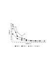
図9は、試験1として、電気分解に使用した水の導電率による水素量の推移を示したグラフである。
ここで、
試験1-1のグラフは、電極ピッチ7mm、電源電圧24V、吐出流量10L/分、
試験1-2のグラフは、電極ピッチ7mm、電源電圧18V、吐出流量10L/分、
試験1-3のグラフは、電極ピッチ7mm、電源電圧24V、吐出流量18L/分、の条件で試験を行なったものである。
Subsequently, the test results such as the hydrogen amount (concentration) of the aqueous solution (hydrogen water) generated by using the hydrogen
FIG. 9 is a graph showing the transition of the amount of hydrogen due to the conductivity of the water used for electrolysis as
here,
The graph of Test 1-1 shows an electrode pitch of 7 mm, a power supply voltage of 24 V, a discharge flow rate of 10 L / min, and
The graph of test 1-2 shows an electrode pitch of 7 mm, a power supply voltage of 18 V, a discharge flow rate of 10 L / min, and
The graph of Test 1-3 shows the test under the conditions of an electrode pitch of 7 mm, a power supply voltage of 24 V, and a discharge flow rate of 18 L / min.
尚、上記「電極ピッチ」は、対向する電極板6同士の間隔である。「電源電圧」は、AC1~4に係るGNDに対する電圧(V+)である。吐出流量は、吐出口22から吐出される流量(Lリットル)である。また、「導電率」は、水中に塩(塩化ナトリウム)を加えて変化させた。試験1は、吐出口からさらに6時間経過後の水素量を示したものである。
The "electrode pitch" is the distance between the opposing
試験1より、特に導電率25mS/mまでは水素量の増加割合が高く、50mS/mを超えると緩やかとなる。また、何れの試験においても、導電率が低い(25mS/m以下)場合には、導電率の増加に対する水素量の増加割合が高いことが示されている。
また、電源電圧の高さによる水素量の増加は、導電率の高さによっては逆転し、電源電圧を低く(18V)しても十分な水素量が得られる。
このため、電気分解用の水については、水道水、自然水等、その水質に応じて、循環流路62の循環の回数を制御することが好ましい。また、水中に予め塩、液肥等を加えて導電率を高めておくことも有効である。
From
Further, the increase in the amount of hydrogen due to the high power supply voltage is reversed depending on the high conductivity, and a sufficient amount of hydrogen can be obtained even if the power supply voltage is low (18 V).
Therefore, regarding the water for electrolysis, it is preferable to control the number of circulations in the
図10は、試験2として、装置から吐出された水溶液(水素水)の水素量の経時変化を示したものである。
ここで、
試験2-1のグラフは、電極ピッチ5mm、稼働時間24時間、導電率30mS/m、電源電圧24V、吐出流量10L/分、
試験2-2のグラフは、電極ピッチ7mm、稼働時間8時間、導電率10mS/m、電源電圧24V、吐出流量10L/分、
試験2-3のグラフは、電極ピッチ7mm、稼働時間8時間、導電率200mS/m、電源電圧18V、吐出流量10L/分、
試験2-4のグラフは、電極ピッチ7mm、稼働時間8時間、導電率200mS/m、電源電圧18V、吐出流量10L/分、の条件で試験を行なったものである。
FIG. 10 shows the change over time in the amount of hydrogen in the aqueous solution (hydrogen water) discharged from the apparatus as
here,
The graph of test 2-1 shows an electrode pitch of 5 mm, an operating time of 24 hours, a conductivity of 30 mS / m, a power supply voltage of 24 V, and a discharge flow rate of 10 L / min.
The graph of test 2-2 shows an electrode pitch of 7 mm, an operating time of 8 hours, a conductivity of 10 mS / m, a power supply voltage of 24 V, and a discharge flow rate of 10 L / min.
The graph of test 2-3 shows an electrode pitch of 7 mm, an operating time of 8 hours, a conductivity of 200 mS / m, a power supply voltage of 18 V, and a discharge flow rate of 10 L / min.
The graph of Test 2-4 is a test conducted under the conditions of an electrode pitch of 7 mm, an operating time of 8 hours, a conductivity of 200 mS / m, a power supply voltage of 18 V, and a discharge flow rate of 10 L / min.
吐出された水溶液の保存について、試験2-1~3はバケツ(開放)で保存し、また試験2-4ではタンク(蓋付の密閉容器)で保存した。稼働時間は、装置の運転時間であり、この稼働時間が長いと再循環による電気分解の繰り返しの回数も多くなる。
その他の条件については、上述したものと同じである。
Regarding the storage of the discharged aqueous solution, tests 2-1 to 3 were stored in a bucket (open), and in test 2-4, they were stored in a tank (closed container with a lid). The operating time is the operating time of the device, and if this operating time is long, the number of times of repeated electrolysis due to recirculation increases.
Other conditions are the same as described above.
試験2より、試験2-1と試験2-3からして、電気分解を行う水の導電率が低い場合(試験2-1)であっても、装置の稼働時間を長く(再循環回数を多く)することにより比較的高い水素量が得られることが示されている。
また、試験2-4(タンク保存)では、特に経過時間が十数時間(h)までは、水素量の経時低下が僅かであり、また他の試験2-1~3と比べて水素量の経時低下の変化が小さい。一方、試験2-1~3(バケツ保存)は、経過時間が二十数時間(h)までは、水素量の経時低下が急であり、それ以降は経時低下が緩やかである。
上記より、装置の稼働時間を長くすることで高い濃度の水素水が得られ、また水素水の保存は蓋付の容器で保存する方が、水素量が高く保持され長持ちすることが確認できた。
From
Further, in Test 2-4 (tank storage), the amount of hydrogen decreased slightly with time, especially until the elapsed time was more than 10 hours (h), and the amount of hydrogen was smaller than that of other Tests 2-1 to 3. The change over time is small. On the other hand, in Tests 2-1 to 3 (bucket storage), the amount of hydrogen decreases rapidly with time until the elapsed time is more than 20 hours (h), and after that, the decrease with time is gradual.
From the above, it was confirmed that high-concentration hydrogen water can be obtained by lengthening the operating time of the device, and that the hydrogen water can be stored in a container with a lid to maintain a high hydrogen content and last longer. ..
図11は、試験3として、装置から吐出される流量による水素量の変化(経時)を示したものである。
ここで、
試験3-1のグラフは、電極ピッチ7mm、導電率30mS/m、電源電圧24V、吐出流量18L/分、
試験3-2のグラフは、電極ピッチ7mm、導電率30mS/m、電源電圧24V、吐出流量10L/分、
試験3-3のグラフは、電極ピッチ7mm、導電率100mS/m、電源電圧18V、吐出流量10L/分、
試験3-4のグラフは、電極ピッチ7mm、導電率100mS/m、電源電圧18V、吐出流量18L/分、
試験3-5のグラフは、電極ピッチ7mm、導電率30mS/m、電源電圧24V、吐出流量10L/分、濾過器使用、の条件で試験を行なったものである。
FIG. 11 shows a change (time) in the amount of hydrogen depending on the flow rate discharged from the device as
here,
The graph of test 3-1 shows an electrode pitch of 7 mm, a conductivity of 30 mS / m, a power supply voltage of 24 V, and a discharge flow rate of 18 L / min.
The graph of test 3-2 shows an electrode pitch of 7 mm, a conductivity of 30 mS / m, a power supply voltage of 24 V, and a discharge flow rate of 10 L / min.
The graph of test 3-3 shows an electrode pitch of 7 mm, a conductivity of 100 mS / m, a power supply voltage of 18 V, and a discharge flow rate of 10 L / min.
The graph of test 3-4 shows an electrode pitch of 7 mm, a conductivity of 100 mS / m, a power supply voltage of 18 V, and a discharge flow rate of 18 L / min.
The graph of Test 3-5 shows the test under the conditions of an electrode pitch of 7 mm, a conductivity of 30 mS / m, a power supply voltage of 24 V, a discharge flow rate of 10 L / min, and a filter.
試験3より、導電率が高い場合(試験3-3,4)は、導電率が低い場合(試験3-1,2,5)と比べて、稼働時間に対する水素量の増加割合が高い。
また、濾過器を使用した場合(試験3-5)は、同条件で濾過器を使用しない場合(試験3-2)と比べて、水素量の増加割合が低い。
また、試験3-3に対する試験3-4のように吐出流量を1.8倍にした場合であっても、水素量は十数%低下する程度であり、吐出量を多少増減したところで得られる水素量に大きな変化はないことが示された。
From
Further, when the filter is used (test 3-5), the rate of increase in the amount of hydrogen is lower than when the filter is not used under the same conditions (test 3-2).
Further, even when the discharge flow rate is increased by 1.8 times as in the test 3-4 with respect to the test 3-3, the hydrogen amount is reduced by about 10%, and it can be obtained when the discharge amount is slightly increased or decreased. It was shown that there was no significant change in the amount of hydrogen.
以上、上記試験1~3から、以下のことが考察される。
・幅広い導電率をカバーするためには、電源電圧18Vとするのが好ましい。
・導電率が30mS/mを下回る場合には、塩、肥料等の添加物を加えて導電率を高めることで、水素量の増大が望める。
・水素量の経時変化から、バケツでの保存では3日程度で100ppbを下回ることから、タンク等で大量に密閉保存することで、水素量の低下が防げて長く保存できる。
・吐出流量は、18L/分より、10L/分の方が優位である。
・濾過器を使用した場合には、水素量が少し低下する。
As mentioned above, the following matters are considered from the
-In order to cover a wide range of conductivity, it is preferable to set the power supply voltage to 18V.
-If the conductivity is less than 30 mS / m, the amount of hydrogen can be expected to increase by adding additives such as salt and fertilizer to increase the conductivity.
-Due to the change over time in the amount of hydrogen, it will be less than 100 ppb in about 3 days when stored in a bucket. Therefore, by storing a large amount in a tank or the like in a sealed manner, the amount of hydrogen can be prevented from decreasing and can be stored for a long time.
-The discharge flow rate is superior to 10 L / min over 18 L / min.
・ When a filter is used, the amount of hydrogen decreases a little.
図12は、上記水素水生成装置2で生成した水溶液(水素水)の粒子濃度(縦軸:E7)及び気泡(バブル)の粒子径(横軸:nm)を示したグラフである。ここで、大きな山のグラフ(a)は上記水素水生成装置2で生成した水溶液(水素水)に係るグラフであり、小さい山のグラフ(b)は、一般の水道水に係るグラフである。なお、水道水に係る粒子は微細な塵であり気泡とは異なる。グラフ(b)は、参考までに示した。
FIG. 12 is a graph showing the particle concentration (vertical axis: E7) of the aqueous solution (hydrogen water) generated by the
上記グラフ(a)から、粒子(気泡)の粒子径が50nm~250nmにわたって、ナノサイズの粒子の生成が見られる。特に、粒子径が70nm~130nmの範囲では、粒子濃度(粒子数)が高くナノサイズの粒子が多く生成されている。
また、水素水生成装置2により生成された粒子(気泡)は、濃度(Concentration)として1mL中の粒子数が2.19・109個(約21億9千万個)/mLであった。ここで、参考までに水道水の1mL中の粒子数は7.05・107個(約7千万個)/mLであった。これを差し引くと、水素水生成装置2により粒子(気泡)が約21億個生成されたことになる。
上記粒子(気泡)内の物質については、具体的な測定を行っていないが、上記試験1~3等の水素量から、水素ガスが含有されているものと推測される。これから、水素水生成装置2により、ナノサイズの気泡(ナノバブル水素水)が大量に生成されていると考えられる。
From the graph (a) above, the formation of nano-sized particles can be seen with the particle size of the particles (bubbles) ranging from 50 nm to 250 nm. In particular, when the particle size is in the range of 70 nm to 130 nm, the particle concentration (number of particles) is high and many nano-sized particles are produced.
The particles (air bubbles) generated by the
The substance in the particles (bubbles) has not been specifically measured, but it is presumed that hydrogen gas is contained from the amount of hydrogen in the
次に、上記水素水生成装置2によって生成した水素水の、植物(農作物の栽培、園芸等)及び畜産(家畜の飼育等)への利用形態について説明する。植物への利用は、主に、葉面散布、潅水及び水耕栽培等が挙げられる。この場合、貯留タンク16から水素水を供給し、植物への散布、潅水等を行う。
Next, a mode of use of the hydrogen water generated by the hydrogen
葉面散布では、例えば、水素水の噴霧用の自動噴霧器或いは動噴器等を用いて、農作物、花等の植物の葉面散布を行う。これは主に、ダニ、アブラムシ、スリップス等の害虫忌避駆除、害虫等の卵の孵化阻害の目的で行なう。
植物への水素水(特にナノバブル水素水)の供給により、病害虫の耐性及び薬害等も無く、農薬の使用回数を減らすことができる。また、害虫の卵は酸化で孵化するが、ナノバブル水素水は還元反応が高いため卵の酸化を防ぎ、孵化を阻害する働きがある。
In foliar spraying, for example, foliar spraying of plants such as agricultural products and flowers is performed using an automatic sprayer or a dynamic sprayer for spraying hydrogen water. This is mainly performed for the purpose of exterminating pests such as mites, thrips and slips, and inhibiting the hatching of eggs such as pests.
By supplying hydrogen water (particularly nanobubble hydrogen water) to plants, there is no resistance to pests and phytotoxicity, and the number of times pesticides are used can be reduced. In addition, pest eggs hatch by oxidation, but nanobubble hydrogen water has a high reduction reaction, so it has the function of preventing egg oxidation and inhibiting hatching.
また、潅水及び水耕栽培では、供給ポンプ等を介して貯留タンク16から水素水を流通させ、植物の根等に水素水を供給する。この場合、例えば、一日程度かけて水素水が畑(農園)を一巡するようにしてもよい。なお、水素水の水素濃度は3日程度残存することが好ましい。
試験によれば、水素水の潅水等により、植物の生育例えば葉などが大きく成長し、植物の生長促進に寄与する。
Further, in irrigation and hydroponics, hydrogen water is circulated from the
According to the test, the growth of plants such as leaves grows greatly by irrigation of hydrogen water and the like, which contributes to the promotion of plant growth.
また、上記水素水生成装置2によって生成した水素水を、家畜(豚、牛、鶏等)の飲料水及び家畜餌に混ぜて使用する。これにより、家畜の健康が維持(病気の発生が減少)され、また糞の量が減り(消化吸収が良いため)、糞の臭気も軽減される等の効果がある。
Further, the hydrogen water generated by the hydrogen
また、上記水素水生成装置2による水素水は、微小な粒子状のナノバブル水素水が多く含まれており、水素濃度を3日程度残存させることは可能である。なお、水素水の貯留タンク16は密閉保存することが好ましく、これにより長期の保存が可能となる。
Further, the hydrogen water produced by the hydrogen
なお、電解槽4で生成された水素水は、そのまま直接植物へ供給することも可能である。
この場合、例えば、水道或いは水源から直接筐体18の吸入口20に水を供給し、更に電解槽4及び濾過器12を通過させて筐体18の吐出口22から吐出される水溶液を、そのまま流路を介して農作物等に供給する。
このとき、貯留タンク16は特に必要としないが、例えば、貯留タンク16をバッファー(緩衝手段)としても用いることも可能である。この場合、電解槽4で生成される水溶液を一度貯留タンク16に蓄えておき、これを植物に供給する。これにより、電解槽4で生成される水素水の量に左右されることなく、常に農作物に必要な量の水素水が供給できる。
The hydrogen water generated in the
In this case, for example, water is directly supplied to the
At this time, the
以上説明したように、この実施例に係る水素水生成装置によれば、効率的に水素を含有する水溶液(水素水)を大量に得ることができ、また電解槽等の装置の小型化が図れ、機能的で経済性にも優れる。また、電解槽内では、水の移動とともに電気分解が行なえて効率的であり、水の移動が淀みなく満遍に行え、良好に電気分解が行なえ水の滞留も防止され、加えて循環流路により繰り返し電解槽を通過させることで、容易に高濃度の水素水を得ることができ、水溶液中の水素濃度の管理も容易である。 As described above, according to the hydrogen water generator according to this embodiment, a large amount of an aqueous solution (hydrogen water) containing hydrogen can be efficiently obtained, and the device such as an electrolytic cell can be downsized. , Functional and economical. In addition, in the electrolytic tank, electrolysis can be performed efficiently with the movement of water, the movement of water can be performed evenly without stagnation, the electrolysis can be performed well, the retention of water can be prevented, and in addition, the circulation flow path. By repeatedly passing through the electrolytic tank, high-concentration hydrogen water can be easily obtained, and the hydrogen concentration in the aqueous solution can be easily controlled.
2 水素水生成装置
4 電解槽
6 電極板
10 制御部
11 電源回路部
12 濾過器
14 ポンプ
16 貯留タンク
30 注入口
32 排出口
62 循環流路
2
Claims (4)
上記電極板を、連続する4枚を一組とし、且つ所定間隔をおいて8枚を互いに向い合せに配置し、これら電極板の並びの一方側に水の注入口を、また他方側に水の排出口をそれぞれ設けた電解槽と、
上記各電極板に電圧を印加し、隣り合う電極板間及び他の電極板を介在させた電極板間に電流を流して電気分解を行わせる電源回路部と、を有し、
上記電源回路部に、上記4枚を一組とする各組に電気を供給する出力回路を、各組毎に個別に設け、
上記電源回路部は、各一組の上記電極板の内、他の電極板を介在させた特定の電極板間に交流電圧を印加し、且つ当該特定の電極板以外の電極板には直流電圧を印加し、電気分解を行わせることとし、
上記電解槽を筐体内に収め、上記電解槽の上部に、下部側に上記8枚の電極板を取り付けた蓋部材を配置し、当該蓋部材を上記電解槽の縁部に固定し、かつ上記電極板を電解槽の中央部寄りにまとめて配置し、上記電極板と上記電解槽の周囲の壁面との間には、水の流通が可能な隙間を形成し、上記蓋部材により上記電解槽の内部を密閉し、
上記筐体における水の吸入口と上記電解槽の上記注入口との間の流路にポンプを配置し、上記ポンプの駆動により水を上記注入口へ向けて流通させ、
上記注入口から給水される水により上記電解槽内部の水が押し出され、これを上記排出口から排出し、当該排出される水の流量を9~12リットル/分とし、併せて、
上記注入口を上記電解槽の下部近傍に設けて水を注入する一方、上記排出口を上記電解槽の上部近傍に設けて、上記注入された水を上記注入口から上記排出口方向へ移動させるとともに、下方から上方へと移動させ、この移動する水を上記電極板により電気分解し、水中に水素を含有する水溶液を生成し、これを上記排出口から排出することを特徴とする水素水生成装置。 With a net-like electrode plate,
Four consecutive electrode plates are arranged as a set, and eight plates are arranged facing each other at predetermined intervals, and a water inlet is provided on one side of the array of these electrode plates and water is placed on the other side. An electrolytic cell with each discharge port and
It has a power supply circuit unit in which a voltage is applied to each of the above electrode plates and a current is passed between adjacent electrode plates and between electrode plates interposed between other electrode plates to perform electrolysis.
In the power supply circuit section, an output circuit for supplying electricity to each set of the above four sets is individually provided for each set.
The power supply circuit unit applies an AC voltage between specific electrode plates interposed between the other electrode plates in each set of the electrode plates, and a DC voltage to the electrode plates other than the specific electrode plates. To perform electrolysis,
The electrolytic cell is housed in a housing, a lid member to which the eight electrode plates are attached is arranged on the lower side of the electrolytic cell, the lid member is fixed to the edge of the electrolytic cell, and the electrolytic cell is fixed. The electrode plates are collectively arranged near the center of the electrolytic cell, a gap through which water can flow is formed between the electrode plate and the wall surface around the electrolytic cell, and the electrolytic cell is provided with the lid member. Seal the inside of
A pump is arranged in the flow path between the water suction port in the housing and the injection port of the electrolytic cell, and the water is circulated toward the injection port by driving the pump.
The water inside the electrolytic cell is pushed out by the water supplied from the inlet, discharged from the discharge port, and the flow rate of the discharged water is set to 9 to 12 liters / minute.
The injection port is provided near the lower part of the electrolytic tank to inject water, while the discharge port is provided near the upper part of the electrolytic tank to move the injected water from the injection port toward the discharge port. At the same time, it is moved from the bottom to the top, and the moving water is electrolyzed by the electrode plate to generate an aqueous solution containing hydrogen in the water, which is discharged from the discharge port. Device.
上記電極板を、連続する4枚を一組とし、且つ所定間隔をおいて8枚を互いに向い合せに配置し、これら電極板の並びの一方側に水の注入口を、また他方側に水の排出口をそれぞれ設けた電解槽と、
上記各電極板に電圧を印加し、隣り合う電極板間及び他の電極板を介在させた電極板間に電流を流して電気分解を行わせる電源回路部と、を有し、
上記電源回路部に、上記4枚を一組とする各組に電気を供給する出力回路を、各組毎に個別に設け、
隣り合う上記電極板間の間隔を5~8mmとし、
上記電源回路部は、各一組の上記電極板の内、他の電極板を介在させた特定の電極板間に交流電圧を印加し、且つ当該特定の電極板以外の電極板には直流電圧を印加する形態とし、
上記組毎に設けた出力回路について、直流電源としての電気信号を印加する回路を接続して一体化し、前記組同士の間の隣り合う電極の内、一方側には交流電圧を印加する電極が配置される形態の場合には、他方側には直流電圧を印加する電極を配置する形態として、電気分解を行わせ、
上記注入口を上記電解槽の下部近傍に設けて水を注入する一方、上記排出口を上記電解槽の上部近傍に設けて、上記注入された水を上記注入口から上記排出口方向へ移動させるとともに、下方から上方へと移動させ、この移動する水を上記電極板により電気分解し、水中に水素を含有する水溶液を生成し、これを上記排出口から排出することを特徴とする水素水生成装置。 With a net-like electrode plate,
Four consecutive electrode plates are arranged as a set, and eight plates are arranged facing each other at predetermined intervals, and a water inlet is provided on one side of the array of these electrode plates and water is placed on the other side. An electrolytic cell with each discharge port and
It has a power supply circuit unit in which a voltage is applied to each of the above electrode plates and a current is passed between adjacent electrode plates and between electrode plates interposed between other electrode plates to perform electrolysis.
In the power supply circuit section, an output circuit for supplying electricity to each set of the above four sets is individually provided for each set.
The distance between the adjacent electrode plates is 5 to 8 mm.
The power supply circuit unit applies an AC voltage between specific electrode plates sandwiched between other electrode plates in each set of the electrode plates, and a DC voltage is applied to the electrode plates other than the specific electrode plates. In the form of applying
Regarding the output circuit provided for each of the above sets, a circuit for applying an electric signal as a DC power supply is connected and integrated, and among the adjacent electrodes between the sets, an electrode for applying an AC voltage is provided on one side. In the case of the arranged form, an electrode for applying a DC voltage is arranged on the other side, and electrolysis is performed.
The injection port is provided near the lower part of the electrolytic tank to inject water, while the discharge port is provided near the upper part of the electrolytic tank to move the injected water from the injection port toward the discharge port. At the same time, it is moved from the bottom to the top, and the moving water is electrolyzed by the electrode plate to generate an aqueous solution containing hydrogen in the water, which is discharged from the discharge port. Device.
上記筐体における水の吸入口と上記電解槽の上記注入口との間の流路にポンプを配置し、上記ポンプの駆動により水を上記注入口へ向けて流通させ、
上記給水される水により上記電解槽内部の水が押し出され、これを上記排出口から排出し、当該排出される水の流量を9~12リットル/分とすることを特徴とする請求項2に記載の水素水生成装置。 The electrolytic cell is housed in a housing, a lid member to which the eight electrode plates are attached is arranged on the lower side of the electrolytic cell, the lid member is fixed to the edge of the electrolytic cell, and the electrolytic cell is fixed. The electrode plates are collectively arranged near the center of the electrolytic cell, a gap through which water can flow is formed between the electrode plate and the wall surface around the electrolytic cell, and the electrolytic cell is provided with the lid member. Seal the inside of
A pump is arranged in the flow path between the water suction port in the housing and the injection port of the electrolytic cell, and the water is circulated toward the injection port by driving the pump.
The second aspect of claim 2 , wherein the water inside the electrolytic cell is pushed out by the water supplied and discharged from the discharge port so that the flow rate of the discharged water is 9 to 12 liters / minute. The hydrogen water generator described.
Priority Applications (1)
| Application Number | Priority Date | Filing Date | Title |
|---|---|---|---|
| JP2020090527A JP6994780B2 (en) | 2020-05-25 | 2020-05-25 | Hydrogen water generator |
Applications Claiming Priority (1)
| Application Number | Priority Date | Filing Date | Title |
|---|---|---|---|
| JP2020090527A JP6994780B2 (en) | 2020-05-25 | 2020-05-25 | Hydrogen water generator |
Related Parent Applications (1)
| Application Number | Title | Priority Date | Filing Date |
|---|---|---|---|
| JP2017196157A Division JP2019069413A (en) | 2017-10-06 | 2017-10-06 | Hydrogen water generation apparatus |
Publications (3)
| Publication Number | Publication Date |
|---|---|
| JP2020121314A JP2020121314A (en) | 2020-08-13 |
| JP2020121314A5 JP2020121314A5 (en) | 2020-09-24 |
| JP6994780B2 true JP6994780B2 (en) | 2022-01-14 |
Family
ID=71991829
Family Applications (1)
| Application Number | Title | Priority Date | Filing Date |
|---|---|---|---|
| JP2020090527A Active JP6994780B2 (en) | 2020-05-25 | 2020-05-25 | Hydrogen water generator |
Country Status (1)
| Country | Link |
|---|---|
| JP (1) | JP6994780B2 (en) |
Citations (8)
| Publication number | Priority date | Publication date | Assignee | Title |
|---|---|---|---|---|
| JP2003220389A (en) | 2002-01-30 | 2003-08-05 | Kosumosu Enterp:Kk | Reduced water former |
| JP2003236543A (en) | 2002-02-14 | 2003-08-26 | Hideo Hayakawa | Alternating current electrolysis method and apparatus for liquid |
| JP2004033963A (en) | 2002-07-05 | 2004-02-05 | Kyushu Hitachi Maxell Ltd | Water treatment apparatus |
| JP2004131746A (en) | 2002-10-08 | 2004-04-30 | Denso Corp | Gaseous hydrogen feeder |
| JP2007307517A (en) | 2006-05-22 | 2007-11-29 | Hideo Hayakawa | Method and apparatus for electrolyzing liquid by using alternating current |
| JP2011131118A (en) | 2009-12-22 | 2011-07-07 | Tanah Process Co Ltd | Method and apparatus for preparing spray water for plant |
| JP2012161795A (en) | 2012-04-04 | 2012-08-30 | Daikin Industries Ltd | Electrolytic apparatus and heat pump type water heater equipped with the same |
| WO2017077992A1 (en) | 2015-11-05 | 2017-05-11 | 株式会社日本トリム | Hydrogen water server |
Family Cites Families (1)
| Publication number | Priority date | Publication date | Assignee | Title |
|---|---|---|---|---|
| JP2623204B2 (en) * | 1993-02-26 | 1997-06-25 | 英雄 早川 | Water reforming method |
-
2020
- 2020-05-25 JP JP2020090527A patent/JP6994780B2/en active Active
Patent Citations (8)
| Publication number | Priority date | Publication date | Assignee | Title |
|---|---|---|---|---|
| JP2003220389A (en) | 2002-01-30 | 2003-08-05 | Kosumosu Enterp:Kk | Reduced water former |
| JP2003236543A (en) | 2002-02-14 | 2003-08-26 | Hideo Hayakawa | Alternating current electrolysis method and apparatus for liquid |
| JP2004033963A (en) | 2002-07-05 | 2004-02-05 | Kyushu Hitachi Maxell Ltd | Water treatment apparatus |
| JP2004131746A (en) | 2002-10-08 | 2004-04-30 | Denso Corp | Gaseous hydrogen feeder |
| JP2007307517A (en) | 2006-05-22 | 2007-11-29 | Hideo Hayakawa | Method and apparatus for electrolyzing liquid by using alternating current |
| JP2011131118A (en) | 2009-12-22 | 2011-07-07 | Tanah Process Co Ltd | Method and apparatus for preparing spray water for plant |
| JP2012161795A (en) | 2012-04-04 | 2012-08-30 | Daikin Industries Ltd | Electrolytic apparatus and heat pump type water heater equipped with the same |
| WO2017077992A1 (en) | 2015-11-05 | 2017-05-11 | 株式会社日本トリム | Hydrogen water server |
Also Published As
| Publication number | Publication date |
|---|---|
| JP2020121314A (en) | 2020-08-13 |
Similar Documents
| Publication | Publication Date | Title |
|---|---|---|
| USRE47665E1 (en) | Flow-through oxygenator | |
| WO2019069734A1 (en) | Hydrogen water generation device | |
| US6802956B2 (en) | Electrolytic treatment of aqueous media | |
| CN201212061Y (en) | Electrolyzed water maker for poultry and livestock farms sterilisation | |
| JP6994780B2 (en) | Hydrogen water generator | |
| RU2628782C1 (en) | Water electroactivation device | |
| JP5385776B2 (en) | Middle water supply equipment | |
| KR101947051B1 (en) | Functional water production system using nano bubble | |
| JP2006204235A (en) | Closed circulation type culture system and ph adjuster | |
| KR101368491B1 (en) | Appliance for electrolysis attached ship and the method of sterilizing red tied using it | |
| JP4929465B2 (en) | Water quality control device for aquarium fish tank | |
| JP2007038090A (en) | Electrolytic ion water generator for fruits and vegetables | |
| JP7481782B1 (en) | Electrolysis device for aquatic organism cultivation, circulating water treatment system for aquatic organism cultivation, and electrolysis method for aquatic organism cultivation | |
| USRE47092E1 (en) | Flow-through oxygenator | |
| JP3238937U (en) | Apparatus for producing modified water and distributing this modified water to agricultural holdings | |
| US20240270614A1 (en) | Water management system | |
| CN206901835U (en) | A kind of electrolysis water sterilization algae removal water circle device | |
| JP3840189B2 (en) | Seafood farming equipment | |
| CN110036965A (en) | A kind of ion cleaning cultivating system | |
| KR20000018274A (en) | Mass storage electrolytic water making and dispersing apparatus | |
| WO2005077831A1 (en) | Electrochemical water treatment method and device | |
| CN103141430A (en) | Tri-polar dual-circulation seawater purifying aerator | |
| CN112939268A (en) | Aquaculture harmless water purification treatment equipment and method | |
| JP2005245328A (en) | Closed circulating culture system | |
| JPH03224683A (en) | Electrochemical treatment of water to be treated |
Legal Events
| Date | Code | Title | Description |
|---|---|---|---|
| A521 | Request for written amendment filed |
Free format text: JAPANESE INTERMEDIATE CODE: A523 Effective date: 20200717 |
|
| A621 | Written request for application examination |
Free format text: JAPANESE INTERMEDIATE CODE: A621 Effective date: 20200717 |
|
| A131 | Notification of reasons for refusal |
Free format text: JAPANESE INTERMEDIATE CODE: A131 Effective date: 20210618 |
|
| A521 | Request for written amendment filed |
Free format text: JAPANESE INTERMEDIATE CODE: A523 Effective date: 20210720 |
|
| TRDD | Decision of grant or rejection written | ||
| A01 | Written decision to grant a patent or to grant a registration (utility model) |
Free format text: JAPANESE INTERMEDIATE CODE: A01 Effective date: 20211203 |
|
| A61 | First payment of annual fees (during grant procedure) |
Free format text: JAPANESE INTERMEDIATE CODE: A61 Effective date: 20211207 |
|
| R150 | Certificate of patent or registration of utility model |
Ref document number: 6994780 Country of ref document: JP Free format text: JAPANESE INTERMEDIATE CODE: R150 |
|
| R250 | Receipt of annual fees |
Free format text: JAPANESE INTERMEDIATE CODE: R250 |