JP6993246B2 - Zinc secondary battery - Google Patents
Zinc secondary battery Download PDFInfo
- Publication number
- JP6993246B2 JP6993246B2 JP2018007644A JP2018007644A JP6993246B2 JP 6993246 B2 JP6993246 B2 JP 6993246B2 JP 2018007644 A JP2018007644 A JP 2018007644A JP 2018007644 A JP2018007644 A JP 2018007644A JP 6993246 B2 JP6993246 B2 JP 6993246B2
- Authority
- JP
- Japan
- Prior art keywords
- negative electrode
- ldh
- zinc
- electrode plate
- positive electrode
- Prior art date
- Legal status (The legal status is an assumption and is not a legal conclusion. Google has not performed a legal analysis and makes no representation as to the accuracy of the status listed.)
- Active
Links
Images


Classifications
-
- Y—GENERAL TAGGING OF NEW TECHNOLOGICAL DEVELOPMENTS; GENERAL TAGGING OF CROSS-SECTIONAL TECHNOLOGIES SPANNING OVER SEVERAL SECTIONS OF THE IPC; TECHNICAL SUBJECTS COVERED BY FORMER USPC CROSS-REFERENCE ART COLLECTIONS [XRACs] AND DIGESTS
- Y02—TECHNOLOGIES OR APPLICATIONS FOR MITIGATION OR ADAPTATION AGAINST CLIMATE CHANGE
- Y02E—REDUCTION OF GREENHOUSE GAS [GHG] EMISSIONS, RELATED TO ENERGY GENERATION, TRANSMISSION OR DISTRIBUTION
- Y02E60/00—Enabling technologies; Technologies with a potential or indirect contribution to GHG emissions mitigation
- Y02E60/10—Energy storage using batteries
-
- Y—GENERAL TAGGING OF NEW TECHNOLOGICAL DEVELOPMENTS; GENERAL TAGGING OF CROSS-SECTIONAL TECHNOLOGIES SPANNING OVER SEVERAL SECTIONS OF THE IPC; TECHNICAL SUBJECTS COVERED BY FORMER USPC CROSS-REFERENCE ART COLLECTIONS [XRACs] AND DIGESTS
- Y02—TECHNOLOGIES OR APPLICATIONS FOR MITIGATION OR ADAPTATION AGAINST CLIMATE CHANGE
- Y02P—CLIMATE CHANGE MITIGATION TECHNOLOGIES IN THE PRODUCTION OR PROCESSING OF GOODS
- Y02P70/00—Climate change mitigation technologies in the production process for final industrial or consumer products
- Y02P70/50—Manufacturing or production processes characterised by the final manufactured product
Description
本発明は、亜鉛二次電池に関するものである。 The present invention relates to a zinc secondary battery.
ニッケル亜鉛二次電池、空気亜鉛二次電池等の亜鉛二次電池では、充電時に負極から金属亜鉛がデンドライト状に析出し、不織布等のセパレータの空隙を貫通して正極に到達し、その結果、短絡を引き起こすことが知られている。このような亜鉛デンドライトに起因する短絡は繰り返し充放電寿命の短縮を招く。 In zinc secondary batteries such as nickel-zinc secondary batteries and air-zinc secondary batteries, metallic zinc precipitates in the form of dendrite from the negative electrode during charging and reaches the positive electrode through the voids of the separator such as non-woven fabric. It is known to cause short circuits. Such a short circuit caused by zinc dendrite shortens the repeated charge / discharge life.
上記問題に対処すべく、水酸化物イオンを選択的に透過させながら、亜鉛デンドライトの貫通を阻止する、層状複水酸化物(LDH)セパレータを備えた電池が提案されている。例えば、特許文献1(国際公開第2013/118561号)には、ニッケル亜鉛二次電池においてLDHセパレータを正極及び負極間に設けることが開示されている。また、特許文献2(国際公開第2016/076047号)には、樹脂製外枠に嵌合又は接合されたLDHセパレータを備えたセパレータ構造体が開示されており、LDHセパレータがガス不透過性及び/又は水不透過性を有する程の高い緻密性を有することが開示されている。また、この文献にはLDHセパレータが多孔質基材と複合化されうることも開示されている。さらに、特許文献3(国際公開第2016/067884号)には多孔質基材の表面にLDH緻密膜を形成して複合材料(LDHセパレータ)を得るための様々な方法が開示されている。この方法は、多孔質基材にLDHの結晶成長の起点を与えうる起点物質を均一に付着させ、原料水溶液中で多孔質基材に水熱処理を施してLDH緻密膜を多孔質基材の表面に形成させる工程を含むものである。 To address the above problems, a battery provided with a layered double hydroxide (LDH) separator that selectively permeates hydroxide ions and blocks the penetration of zinc dendrites has been proposed. For example, Patent Document 1 (International Publication No. 2013/118561) discloses that an LDH separator is provided between a positive electrode and a negative electrode in a nickel-zinc secondary battery. Further, Patent Document 2 (International Publication No. 2016/076047) discloses a separator structure including an LDH separator fitted or bonded to a resin outer frame, and the LDH separator is gas impermeable and has a gas impermeable property. / Or it is disclosed that it has a high degree of density enough to have water impermeableness. The document also discloses that LDH separators can be composited with porous substrates. Further, Patent Document 3 (International Publication No. 2016/067884) discloses various methods for forming an LDH dense film on the surface of a porous substrate to obtain a composite material (LDH separator). In this method, a starting substance that can give a starting point for LDH crystal growth is uniformly adhered to the porous substrate, and the porous substrate is subjected to hydrothermal treatment in an aqueous solution of the raw material to form an LDH dense film on the surface of the porous substrate. It includes a step of forming the above.
上述したようなLDHセパレータを用いてニッケル亜鉛電池等の亜鉛二次電池を構成した場合、亜鉛デンドライトによる短絡等を防止できる。そして、この効果を最大限に発揮させるためには、LDHセパレータで正極と負極を確実に隔離することが望まれる。特に、かかる構成を確保しながら、高電圧や大電流を得るために、複数の正極及び複数の負極を組み合わせて積層電池を容易に組み立てることができれば極めて好都合である。しかしながら、従来の亜鉛二次電池におけるLDHセパレータによる正極と負極の隔離は、LDHセパレータと電池容器とを液密性を確保するように樹脂枠や接着剤等を用いて巧妙かつ入念に封止接合することにより行われており、電池構成や製造工程が複雑化しやすかった。このような電池構成や製造工程の複雑化は積層電池を構成する場合にはとりわけ顕著なものとなりうる。これは積層電池を構成する複数の単電池の各々に対して液密性確保のための封止接合を行う必要があるためである。 When a zinc secondary battery such as a nickel-zinc battery is configured by using the LDH separator as described above, a short circuit or the like due to zinc dendrite can be prevented. Then, in order to maximize this effect, it is desired to surely isolate the positive electrode and the negative electrode with an LDH separator. In particular, it is extremely convenient if a laminated battery can be easily assembled by combining a plurality of positive electrodes and a plurality of negative electrodes in order to obtain a high voltage and a large current while ensuring such a configuration. However, in the conventional zinc secondary battery, the positive electrode and the negative electrode are separated by the LDH separator, and the LDH separator and the battery container are cleverly and carefully sealed and joined by using a resin frame or an adhesive so as to ensure liquidtightness. This was done by doing so, and the battery configuration and manufacturing process tended to be complicated. Such complexity of the battery configuration and the manufacturing process can be particularly remarkable when constructing a laminated battery. This is because it is necessary to perform sealing bonding for ensuring liquidtightness for each of the plurality of cells constituting the laminated battery.
本発明者らは、今般、長尺状のLDHセパレータをつづら折り構造とし、それにより形成される複数の区画に正極板及び負極板を交互に収容する構成とすることで、LDHセパレータと電池容器との煩雑な封止接合を不要として、亜鉛デンドライト伸展を防止可能な亜鉛二次電池の積層電池を、短縮化された作業時間で効率良く組立可能な簡素な構成で提供できるとの知見を得た。 The present inventors have recently made a long LDH separator into a zigzag structure, and by alternately accommodating a positive electrode plate and a negative electrode plate in a plurality of compartments formed by the folded structure, the LDH separator and the battery container can be obtained. It was found that it is possible to provide a laminated battery of a zinc secondary battery that can prevent the spread of zinc dendrites in a simple configuration that can be efficiently assembled in a shortened working time without the need for complicated sealing and joining. ..
したがって、本発明の目的は、亜鉛デンドライト伸展を防止可能な亜鉛二次電池の積層電池を、短縮化された作業時間で効率良く組立可能な簡素な構成で提供することにある。 Therefore, an object of the present invention is to provide a laminated battery of a zinc secondary battery capable of preventing zinc dendrite extension in a simple configuration that can be efficiently assembled with a shortened working time.
本発明の一態様によれば、
複数の正極板と、
亜鉛、酸化亜鉛、亜鉛合金及び亜鉛化合物からなる群から選択される少なくとも1種を含む負極活物質層を含む、複数の負極板と、
高分子材料製の多孔質基材、並びに水酸化物イオン伝導性及びガス不透過性を呈するように前記多孔質基材の孔を塞ぐ層状複水酸化物(LDH)を含む、長尺状のLDHセパレータと、
電解液と、
を含み、前記長尺状のLDHセパレータがつづら折り構造をなしており、該つづら折り構造によって形成される複数の区画に前記正極板及び前記負極板が交互に収容され、それにより前記LDHセパレータを介して前記正極板と前記負極板が互いに隔離される、亜鉛二次電池が提供される。
According to one aspect of the invention
With multiple positive electrode plates,
A plurality of negative electrode plates comprising a negative electrode active material layer containing at least one selected from the group consisting of zinc, zinc oxide, zinc alloys and zinc compounds.
Elongated, including a porous substrate made of a polymer material and a layered double hydroxide (LDH) that closes the pores of the porous substrate so as to exhibit hydroxide ion conductivity and gas impermeableness. LDH separator and
With the electrolyte
The long LDH separator has a zigzag structure, and the positive electrode plate and the negative electrode plate are alternately housed in a plurality of compartments formed by the zigzag structure, whereby the LDH separator is interposed therein. A zinc secondary battery is provided in which the positive electrode plate and the negative electrode plate are separated from each other.
亜鉛二次電池
本発明の亜鉛二次電池は、亜鉛を負極として用い、かつ、アルカリ電解液(典型的にはアルカリ金属水酸化物水溶液)を用いた二次電池であれば特に限定されない。したがって、ニッケル亜鉛二次電池、酸化銀亜鉛二次電池、酸化マンガン亜鉛二次電池、空気亜鉛二次電池、その他各種のアルカリ亜鉛二次電池であることができる。例えば、正極が水酸化ニッケル及び/又はオキシ水酸化ニッケルを含み、それにより亜鉛二次電池がニッケル亜鉛二次電池をなすのが好ましい。あるいは、正極が空気極であり、それにより亜鉛二次電池が空気亜鉛二次電池をなしてもよい。
Zinc secondary battery The zinc secondary battery of the present invention is not particularly limited as long as it is a secondary battery using zinc as a negative electrode and using an alkaline electrolytic solution (typically, an alkaline metal hydroxide aqueous solution). Therefore, it can be a nickel-zinc secondary battery, a silver-zinc oxide secondary battery, a manganese zinc oxide secondary battery, an air-zinc secondary battery, and various other alkaline zinc secondary batteries. For example, it is preferable that the positive electrode contains nickel hydroxide and / or nickel oxyhydroxide, whereby the zinc secondary battery forms a nickel-zinc secondary battery. Alternatively, the positive electrode may be an air electrode, whereby the zinc secondary battery may be an air zinc secondary battery.
図1~4に本発明の亜鉛二次電池の一例が示される。図1~4に示される亜鉛二次電池10は、電池要素11を備えており、電池要素11は、複数の正極板12、複数の負極板16、層状複水酸化物(LDH)セパレータ22、及び電解液(図示せず)を含む。負極板16は、亜鉛、酸化亜鉛、亜鉛合金及び亜鉛化合物からなる群から選択される少なくとも1種を含む負極活物質層17を含む。LDHセパレータ22は、高分子材料製の多孔質基材、並びに水酸化物イオン伝導性及びガス不透過性を呈するように多孔質基材の孔を塞ぐ層状複水酸化物(LDH)を含む。なお、本明細書において「LDHセパレータ」は、LDHを含むセパレータであって、専らLDHの水酸化物イオン伝導性を利用して水酸化物イオンを選択的に通すものとして定義される。LDHセパレータ22は長尺状(典型的には長方形状)であり、この長尺状のセパレータ22がつづら折り構造をなしている。本明細書において「つづら折り構造」(つづら折り形状と称してもよい)は、長尺状物(ここではLDHセパレータ22)がジグザグ状に複数回折り返されることで形成される積層構造ないしその形状を意味するものとする。このつづら折り構造によって形成される複数の区画に正極板12及び負極板16が交互に収容され、それによりLDHセパレータ22を介して正極板12と負極板16が互いに隔離される。このように、長尺状のLDHセパレータ22をつづら折り構造とし、それにより形成される複数の区画に正極板12及び負極板16を交互に収容する構成とすることで、LDHセパレータ22と電池容器との煩雑な封止接合を不要として、亜鉛デンドライト伸展を防止可能な亜鉛二次電池の積層電池を、短縮化された作業時間で効率良く組立可能な簡素な構成で提供することができる。
FIGS. 1 to 4 show an example of the zinc secondary battery of the present invention. The zinc
すなわち、前述のとおり、従来の亜鉛二次電池におけるLDHセパレータによる正極と負極の隔離は、LDHセパレータと電池容器とを液密性を確保するように樹脂枠や接着剤等を用いて巧妙かつ入念に封止接合することにより行われており、電池構成や製造工程が複雑化しやすかった。このような電池構成や製造工程の複雑化は積層電池を構成する場合にはとりわけ顕著なものとなりうる。この点、本発明の亜鉛二次電池10で採用される、高分子材料製の多孔質基材を含むLDHセパレータ22は、フレキシブル性を有するが故に折り曲げやすいとの利点を有する。このため、図2に示されるように、LDHセパレータ22を長尺状に形成してそれをつづら折り状に折り曲げることで、外縁の1辺が閉じた状態を容易に形成することができる。そして、LDHセパレータ22のつづら折り構造によって形成される複数の区画に正極板12及び負極板16が交互に収容される構成とすることで、LDHセパレータ22で仕切られた負極区画に亜鉛デンドライトによる短絡等を防止できる機能を持たせることができる。したがって、正極板12と負極板16をつづら折り構造によって形成された所定の区画に挿入するだけで、LDHセパレータによる正極板12と負極板16の隔離を実現しながら、複数の単電池を備えた積層電池を作製することができる。これはいわゆる組電池ないし積層電池の構成であり、高電圧や大電流が得られる点で有利であるのは勿論のこと、LDHセパレータで正極と負極を隔離するために従来行われていた巧妙かつ入念な封止接合を効率化できる点でも極めて有利である。また、負極板16を1枚ずつLDHセパレータで包み込む煩雑な工程が不要となるため、作業時間を短縮化できる。さらに、つづら折り状のLDHセパレータ22の外縁1辺(LDHセパレータ22端部の重なり部分)の封止を熱溶着又は超音波溶着等の効率的な封止手法により一括で行うことができるため、作業時間をさらに短縮化できる。しかも、長尺状のLDHセパレータ22を、負極板1枚分のサイズに切断することを要しないで使用できるため、セパレータ切断工程を効率化ないし省略することできる。したがって、亜鉛デンドライト伸展を防止可能な亜鉛二次電池の積層電池を、短縮化された作業時間で効率良く組立可能な簡素な構成で提供することができる。
That is, as described above, the separation of the positive electrode and the negative electrode by the LDH separator in the conventional zinc secondary battery is skillfully and carefully performed by using a resin frame, an adhesive or the like so as to secure the liquidtightness between the LDH separator and the battery container. This is done by sealing and joining to the battery, which tends to complicate the battery configuration and manufacturing process. Such complexity of the battery configuration and the manufacturing process can be particularly remarkable when constructing a laminated battery. In this respect, the
典型的には、図1に示されるように、LDHセパレータ22の端部の少なくとも1辺Cが封止されており、この少なくとも1辺Cはつづら折り構造の折り目Fと接続する辺を含む。こうすることで、負極活物質層17を正極板12から確実に隔離することができ、亜鉛デンドライトの伸展をより効果的に防止することができる。この場合、封止された少なくとも1辺Cとつづら折り構造の折り目Fとが負極板16を収容する区画を個別化し、及び/又は封止された少なくとも1辺Cとつづら折り構造の折り目Fとが正極板12を収容する区画を個別化するのが好ましい。特に好ましくは、封止された少なくとも1辺Cとつづら折り構造の折り目Fとが、負極板16を収容する区画と正極板12を収容する区画の両方を個別化し、封止された少なくとも1辺Cはつづら折り構造によるLDHセパレータ22端部の重なり部分が一体的に封止されたものである。こうすることで、LDHセパレータ22の1辺の封止を一度に行うことができるため、作業時間を大幅に短縮することができ、封止作業の更なる効率化が図れる。なお、LDHセパレータ22の折り目Fは、図1に示されるように曲面状に折り曲げられた形状であるのがLDHセパレータ22の性能保持の観点から望ましいが、LDHセパレータ22の性能を損なわないかぎり、鋭角状又は矩形状に折り曲げられた形状であってもよい。
Typically, as shown in FIG. 1, at least one side C of the end of the
本発明の好ましい態様によれば、正極板12、負極板16、及びLDHセパレータ22がそれぞれ縦向きとなり、かつ、LDHセパレータ22の封止された辺Cが下端となるように、電池要素11が配置されており、その結果、正極集電体延出部14a及び負極集電体延出部18aが電池要素11の互いに反対の側端部から横に延出している。こうすることで、より一層集電しやすくなるとともに、LDHセパレータ22の外縁の上端1辺を開放させる場合(これについては後述する)に、上部開放部に障害物が無くなるため、正極板12と負極板16との間でのガスの流出入がより一層しやすくなる。
According to a preferred embodiment of the present invention, the
ところで、つづら折り状のLDHセパレータ22の外縁の1辺又は2辺は開放されていてもよい。例えば、LDHセパレータ22の外縁の上端1辺を開放させておいても、亜鉛二次電池作製時にその上端1辺に電解液が達しないように液を注入すれば、当該上端1辺には電解液が無いことになるため、液漏れや亜鉛デンドライト伸展の問題を回避することができる。これに関連して、電池要素11は密閉容器でありうるケース28内に正極板12とともに収容され、所望により蓋26で塞がれることにより、密閉型亜鉛二次電池の主要構成部品として機能しうる。このため、密閉性は最終的に収容されることになるケース28において確保すれば足りるので、電池要素11自体は上部開放型の簡素な構成であることができる。また、LDHセパレータ22の外縁の1辺を開放させておくことで、そこから負極集電体延出部18aを延出させることもできる。
By the way, one or two sides of the outer edge of the
LDHセパレータ22の上端となる1辺の外縁は開放されているのが好ましい。この上部開放型の構成はニッケル亜鉛電池等における過充電時の問題への対処を可能とするものである。すなわち、ニッケル亜鉛電池等において過充電されると正極板12で酸素(O2)が発生しうるが、LDHセパレータ22は水酸化物イオンしか実質的に通さないといった高度な緻密性を有するが故に、O2を通さない。この点、上部開放型の構成によれば、ケース28内において、O2を正極板12の上方に逃がして上部開放部を介して負極板16側へと送り込むことができ、それによってO2で負極活物質層17のZnを酸化してZnOへと戻すことができる。このような酸素反応サイクルを経ることで、上部開放型の電池要素11を密閉型亜鉛二次電池に用いることで過充電耐性を向上させることができる。なお、LDHセパレータ22の上端となる1辺の外縁が閉じられている場合であっても、閉じられた外縁の一部に通気孔を設けることで上記開放型の構成と同様の効果が期待できる。例えば、LDHセパレータ22の上端となる1辺の外縁を封止した後に通気孔を開けてもよいし、封止の際、通気孔が形成されるように上記外縁の一部を非封止としてもよい。
It is preferable that the outer edge of one side, which is the upper end of the
LDHセパレータ22の少なくとも1辺Cの封止は、いかなる手法で行ってもよい。封止手法の好ましい例としては、接着剤、熱溶着、超音波溶着、接着テープ、封止テープ、及びそれらの組合せが挙げられる。熱溶着及び超音波溶着は市販のヒートシーラー等を用いて行えばよいが、LDHセパレータ22同士の封止の場合、外周部分を構成するLDHセパレータ22の間に保液部材20の外周部分を挟み込むようにして熱溶着及び超音波溶着を行うのが、より効果的な封止を行える点で好ましい。一方、接着剤、接着テープ及び封止テープは市販品を用いればよいが、アルカリ電解液中での劣化を防ぐため、耐アルカリ性を有する樹脂を含むものが好ましい。かかる観点から、好ましい接着剤の例としては、エポキシ樹脂系接着剤、天然樹脂系接着剤、変性オレフィン樹脂系接着剤、及び変成シリコーン樹脂系接着剤が挙げられ、中でもエポキシ樹脂系接着剤が耐アルカリ性に特に優れる点でより好ましい。エポキシ樹脂系接着剤の製品例としては、エポキシ接着剤Hysol(登録商標)(Henkel製)が挙げられる。
At least one side C of the
正極板12は、正極活物質層13を含む。正極活物質層13は、亜鉛二次電池の種類に応じて公知の正極材料を適宜選択すればよく、特に限定されない。例えば、ニッケル亜鉛二次電池の場合には、水酸化ニッケル及び/又はオキシ水酸化ニッケルを含む正極を用いればよい。あるいは、空気亜鉛二次電池の場合には、空気極を正極として用いればよい。正極板12は正極集電体(図示せず)をさらに備えるのが好ましい。また、正極集電体が正極板12を収容する区画から延出する正極集電体延出部14aを有するのが好ましい。正極集電体延出部14aは、正極板12が収容される区画におけるつづら折り構造の折り目Fから遠ざかる方向に延出しているのが特に好ましい。こうすることで、正極集電体延出部14aと負極集電体延出部18aを互いに反対方向に延出させることができ、正極集電体と負極集電体18の不用意な接触を確実に回避可能な、極めて集電しやすい構造を実現することができる。正極集電体の好ましい例としては、発泡ニッケル板等のニッケル製多孔質基板が挙げられる。この場合、例えば、ニッケル製多孔質基板上に水酸化ニッケル等の電極活物質を含むペーストを均一に塗布して乾燥させることにより正極/正極集電体からなる正極板を好ましく作製することができる。その際、乾燥後の正極板(すなわち正極/正極集電体)にプレス処理を施して、電極活物質の脱落防止や電極密度の向上を図ることも好ましい。なお、図2に示される正極板12は正極集電体(例えば発泡ニッケル)を含むものであるが図示されていない。これは、正極集電体が正極活物質層13と渾然一体化しているため、正極集電体を個別に描出できないためである。亜鉛二次電池10は、正極集電体延出部14aの先端に接続する正極集電板14bをさらに備えるのが好ましく、より好ましくは複数枚の正極集電体延出部14aが1つの正極集電板14bに接続される。こうすることで簡素な構成でスペース効率良く集電を行えるとともに、正極端子14cへの接続もしやすくなる。例えば、複数の正極集電体延出部14aを束ねて1つの正極集電板14bないし正極端子14cに接続することができる。また、正極集電板14b自体を正極端子として用いてもよい。
The
負極板16は負極活物質層17を含む。負極活物質層17は、亜鉛、酸化亜鉛、亜鉛合金及び亜鉛化合物からなる群から選択される少なくとも1種を含む。すなわち、亜鉛は、負極に適した電気化学的活性を有するものであれば、亜鉛金属、亜鉛化合物及び亜鉛合金のいずれの形態で含まれていてもよい。負極材料の好ましい例としては、酸化亜鉛、亜鉛金属、亜鉛酸カルシウム等が挙げられるが、亜鉛金属及び酸化亜鉛の混合物がより好ましい。負極活物質層17はゲル状に構成してもよいし、電解液と混合して負極合材としてもよい。例えば、負極活物質に電解液及び増粘剤を添加することにより容易にゲル化した負極を得ることができる。増粘剤の例としては、ポリビニルアルコール、ポリアクリル酸塩、CMC、アルギン酸等が挙げられるが、ポリアクリル酸が強アルカリに対する耐薬品性に優れているため好ましい。
The
亜鉛合金として、無汞化亜鉛合金として知られている水銀及び鉛を含まない亜鉛合金を用いることができる。例えば、インジウムを0.01~0.06質量%、ビスマスを0.005~0.02質量%、アルミニウムを0.0035~0.015質量%を含む亜鉛合金が水素ガス発生の抑制効果があるので好ましい。とりわけ、インジウムやビスマスは放電性能を向上させる点で有利である。亜鉛合金の負極への使用は、アルカリ性電解液中での自己溶解速度を遅くすることで、水素ガス発生を抑制して安全性を向上できる。 As the zinc alloy, a mercury- and lead-free zinc alloy known as a non-mercury zinc alloy can be used. For example, a zinc alloy containing 0.01 to 0.06% by mass of indium, 0.005 to 0.02% by mass of bismuth, and 0.0035 to 0.015% by mass of aluminum has an effect of suppressing hydrogen gas generation. Therefore, it is preferable. In particular, indium and bismuth are advantageous in improving discharge performance. When the zinc alloy is used for the negative electrode, the self-dissolution rate in the alkaline electrolytic solution is slowed down, so that the generation of hydrogen gas can be suppressed and the safety can be improved.
負極材料の形状は特に限定されないが、粉末状とすることが好ましく、それにより表面積が増大して大電流放電に対応可能となる。好ましい負極材料の平均粒径は、亜鉛合金の場合、90~210μmの範囲であり、この範囲内であると表面積が大きいことから大電流放電への対応に適するとともに、電解液及びゲル化剤と均一に混合しやすく、電池組み立て時の取り扱い性も良い。 The shape of the negative electrode material is not particularly limited, but it is preferably in the form of powder, which increases the surface area and makes it possible to cope with a large current discharge. In the case of a zinc alloy, the average particle size of the preferred negative electrode material is in the range of 90 to 210 μm, and if it is within this range, the surface area is large, so that it is suitable for dealing with a large current discharge, and also with an electrolytic solution and a gelling agent. It is easy to mix evenly and is easy to handle when assembling the battery.
負極板16は負極集電体18をさらに備えるのが好ましい。また、負極集電体18が負極板16を収容する区画から延出する負極集電体延出部18aを有する。負極集電体延出部18aが、負極板16が収容される区画におけるつづら折り構造の折り目Fから遠ざかる方向に延出しているのが特に好ましい。こうすることで、正極集電体延出部14aと負極集電体延出部18aを互いに反対方向に延出させることができ、正極集電体と負極集電体18の不用意な接触を確実に回避可能な、極めて集電しやすい構造を実現することができる。亜鉛二次電池10は、負極集電体延出部18aの先端に接続する負極集電板18bをさらに備えるのが好ましく、より好ましくは複数枚の負極集電体延出部18aが1つの負極集電板18bに接続される。こうすることで簡素な構成でスペース効率良く集電を行えるとともに、負極端子18cへの接続もしやすくなる。例えば、複数の負極集電体延出部18aを束ねて1つの負極集電板18bないし負極端子18cに接続することができる。また、負極集電板18b自体を負極端子として用いてもよい。典型的には、負極集電体延出部18aの先端部分がLDHセパレータ22及び(存在する場合には)保液部材20で覆われない露出部分をなす。これにより露出部分を介して負極集電体18(特に負極集電体延出部18a)を負極集電板18b及び/又は負極端子18cに望ましく接続することができる。この場合、図6に示されるように、LDHセパレータ22が負極活物質層17の負極集電体延出部18a側の端部を十分に隠すように所定のマージンM(例えば1~5mmの間隔)を伴って覆う又は包み込むのが好ましい。こうすることで、負極活物質層17の負極集電体延出部18a側の端部又はその近傍からの亜鉛デンドライトの伸展をより効果的に防止することができる。
It is preferable that the
負極集電体18の好ましい例としては、銅箔、銅エキスパンドメタル、銅パンチングメタルが挙げられるが、より好ましくは銅エキスパンドメタルである。この場合、例えば、銅エキスパンドメタル上に、酸化亜鉛粉末及び/又は亜鉛粉末、並びに所望によりバインダー(例えばポリテトラフルオロエチレン粒子)を含んでなる混合物を塗布して負極/負極集電体からなる負極板を好ましく作製することができる。その際、乾燥後の負極板(すなわち負極/負極集電体)にプレス処理を施して、電極活物質の脱落防止や電極密度の向上を図ることも好ましい。
Preferred examples of the negative electrode
好ましくは、負極板16が保液部材20で覆われており、保液部材20に電解液が含浸されている。こうすることで、負極活物質層17とLDHセパレータ22との間に電解液を万遍なく存在させることができ、負極活物質層17とLDHセパレータ22との間における水酸化物イオンの授受を効率良く行うことができる。保液部材20は電解液を保持可能な部材であれば特に限定されないが、シート状の部材であるのが好ましい。保液部材の好ましい例としては不織布、吸水性樹脂、保液性樹脂、多孔シート、各種スペーサが挙げられるが、特に好ましくは、低コストで性能の良い負極構造体を作製できる点で不織布である。保液部材20は0.01~0.20mmの厚さを有するのが好ましく、より好ましくは0.02~0.20mmであり、さらに好ましくは0.02~0.15mmであり、特に好ましくは0.02~0.10mmであり、最も好ましくは0.02~0.06mmである。上記範囲内の厚さであると、負極構造体の全体サイズを無駄無くコンパクトに抑えながら、保液部材20内に十分な量の電解液を保持させることができる。
Preferably, the
負極活物質層17の全体はLDHセパレータ22で覆う又は包み込まれている。図5A及び5Bに負極活物質層17がLDHセパレータ22で覆われた又は包み込まれた負極板16の好ましい態様が示される。図5A及び5Bに示される負極構造体は、負極活物質層17、負極集電体18、及び所望により保液部材20を備えており、負極活物質層17の全体が(必要に応じて保液部材20を介して)LDHセパレータ22で覆う又は包み込まれている。このように、負極活物質層17の全体を(必要に応じて保液部材20を介して)LDHセパレータ22で覆う又は包み込むことにより、前述したように、LDHセパレータ22と電池容器との煩雑な封止接合を不要にして、亜鉛デンドライト伸展を防止可能な亜鉛二次電池の積層電池を極めて簡便にかつ高い生産性で作製することが可能となる。
The entire negative electrode
図5A及び5Bにおいて保液部材20はつづら折り状のLDHセパレータ22よりも小さいサイズとして描かれているが、保液部材20はつづら折り状のLDHセパレータ22と同じサイズであってもよく、保液部材20の外縁はLDHセパレータ22の外縁に到達しうる。すなわち、外周部分を構成するLDHセパレータ22の間に、保液部材20の外周部分が挟み込まれる構成としてもよい。こうすることで、後述するLDHセパレータ22の外縁封止を熱溶着又は超音波溶着により、効果的に行うことができる。すなわち、LDHセパレータ22同士を直接的に熱溶着又は超音波溶着するよりも、LDHセパレータ22同士をそれらの間に熱溶着性の保液部材20を介在させて間接的に熱溶着又は超音波溶着する方が、保液部材20自体の熱溶着性を利用できる結果、より効果的な封止を行うことができる。例えば、保液部材20の封止されるべき端部をあたかもホットメルト接着剤かのごとく利用することができる。この場合における保液部材20の好ましい例としては不織布、特に熱可塑性樹脂(例えばポリエチレン、ポリプロピレン)製の不織布が挙げられる。
In FIGS. 5A and 5B, the liquid-retaining
LDHセパレータ22は、LDHと多孔質基材とを含む。前述のとおり、LDHセパレータ22が水酸化物イオン伝導性及びガス不透過性を呈するように(それ故水酸化物イオン伝導性を呈するLDHセパレータとして機能するように)LDHが多孔質基材の孔を塞いでいる。多孔質基材は高分子材料製であり、LDHは高分子材料製多孔質基材の厚さ方向の全域にわたって組み込まれているのが特に好ましい。LDHセパレータ22の各種好ましい態様については後に詳述するものとする。
The
LDHセパレータ22の枚数は、典型的には1であるが、2以上であってもよい。例えば、数枚重ねのLDHセパレータ22をつづら折り状に折り曲げて、所定の区画に正極板12及び負極板16を収納する構成としてもよい。
The number of
電解液はアルカリ金属水酸化物水溶液を含むのが好ましい。電解液は図示していないが、これは正極板12(特に正極活物質層13)及び負極板16(特に負極活物質層17)の全体に行き渡っているためである。アルカリ金属水酸化物の例としては、水酸化カリウム、水酸化ナトリウム、水酸化リチウム、水酸化アンモニウム等が挙げられるが、水酸化カリウムがより好ましい。亜鉛及び/又は酸化亜鉛の自己溶解を抑制するために、電解液中に酸化亜鉛、水酸化亜鉛等の亜鉛化合物を添加してもよい。前述のとおり、電解液は正極活物質及び/又は負極活物質と混合させて正極合材及び/又は負極合材の形態で存在させてもよい。また、電解液の漏洩を防止するために電解液をゲル化してもよい。ゲル化剤としては電解液の溶媒を吸収して膨潤するようなポリマーを用いるのが望ましく、ポリエチレンオキサイド、ポリビニルアルコール、ポリアクリルアミドなどのポリマーやデンプンが用いられる。 The electrolytic solution preferably contains an aqueous alkali metal hydroxide solution. Although the electrolytic solution is not shown, this is because it is spread over the entire positive electrode plate 12 (particularly the positive electrode active material layer 13) and the negative electrode plate 16 (particularly the negative electrode active material layer 17). Examples of the alkali metal hydroxide include potassium hydroxide, sodium hydroxide, lithium hydroxide, ammonium hydroxide and the like, but potassium hydroxide is more preferable. Zinc compounds such as zinc oxide and zinc hydroxide may be added to the electrolytic solution in order to suppress the self-dissolution of zinc and / or zinc oxide. As described above, the electrolytic solution may be mixed with the positive electrode active material and / or the negative electrode active material and exist in the form of a positive electrode mixture and / or a negative electrode mixture. Further, the electrolytic solution may be gelled in order to prevent leakage of the electrolytic solution. As the gelling agent, it is desirable to use a polymer that absorbs the solvent of the electrolytic solution and swells, and polymers such as polyethylene oxide, polyvinyl alcohol, and polyacrylamide, and starch are used.
図4に示されるように、亜鉛二次電池10は、複数の電池要素11を収容するケース28をさらに備えうる。電池要素11を収容するケース28は樹脂製であるのが好ましい。ケース28を構成する樹脂は水酸化カリウム等のアルカリ金属水酸化物に対する耐性を有する樹脂であるのが好ましく、より好ましくはポリオレフィン樹脂、ABS樹脂、又は変性ポリフェニレンエーテルであり、さらに好ましくはABS樹脂又は変性ポリフェニレンエーテルである。また、2以上のケース28が配列されたケース群を外枠内に収容して、電池モジュールの構成としてもよい。
As shown in FIG. 4, the zinc
LDHセパレータ
LDHセパレータ22は層状複水酸化物(LDH)を含むセパレータであり、亜鉛二次電池に組み込まれた場合に、正極板と負極板とを水酸化物イオン伝導可能に隔離するものである。すなわち、LDHセパレータ22は水酸化物イオン伝導セパレータとしての機能を呈する。好ましいLDHセパレータ22はガス不透過性及び/又は水不透過性を有する。換言すれば、LDHセパレータ22はガス不透過性及び/又は水不透過性を有するほどに緻密化されているのが好ましい。なお、本明細書において「ガス不透過性を有する」とは、特許文献2及び3に記載されるように、水中で測定対象物の一面側にヘリウムガスを0.5atmの差圧で接触させても他面側からヘリウムガスに起因する泡の発生がみられないことを意味する。また、本明細書において「水不透過性を有する」とは、特許文献2及び3に記載されるように、測定対象物の一面側に接触した水が他面側に透過しないことを意味する。すなわち、LDHセパレータ22がガス不透過性及び/又は水不透過性を有するということは、LDHセパレータ22が気体又は水を通さない程の高度な緻密性を有することを意味し、透水性又はガス透過性を有する多孔性フィルムやその他の多孔質材料ではないことを意味する。こうすることで、LDHセパレータ22は、その水酸化物イオン伝導性に起因して水酸化物イオンのみを選択的に通すものとなり、電池用セパレータとしての機能を呈することができる。このため、充電時に生成する亜鉛デンドライトによるセパレータの貫通を物理的に阻止して正負極間の短絡を防止するのに極めて効果的な構成となっている。LDHセパレータ22は水酸化物イオン伝導性を有するため、正極板と負極板との間で必要な水酸化物イオンの効率的な移動を可能として正極板及び負極板における充放電反応を実現することができる。
LDH Separator
LDHセパレータ22は、単位面積あたりのHe透過度が10cm/min・atm以下であるのが好ましく、より好ましくは5.0cm/min・atm以下、さらに好ましくは1.0cm/min・atm以下である。He透過度が10cm/min・atm以下であるセパレータは、電解液中においてZnの透過(典型的には亜鉛イオン又は亜鉛酸イオンの透過)を極めて効果的に抑制することができる。このように本態様のセパレータは、Zn透過が顕著に抑制されることで、亜鉛二次電池に用いた場合に亜鉛デンドライトの成長を効果的に抑制できるものと原理的に考えられる。He透過度は、セパレータの一方の面にHeガスを供給してセパレータにHeガスを透過させる工程と、He透過度を算出して水酸化物イオン伝導セパレータの緻密性を評価する工程とを経て測定される。He透過度は、単位時間あたりのHeガスの透過量F、Heガス透過時にセパレータに加わる差圧P、及びHeガスが透過する膜面積Sを用いて、F/(P×S)の式により算出する。このようにHeガスを用いてガス透過性の評価を行うことにより、極めて高いレベルでの緻密性の有無を評価することができ、その結果、水酸化物イオン以外の物質(特に亜鉛デンドライト成長を引き起こすZn)を極力透過させない(極微量しか透過させない)といった高度な緻密性を効果的に評価することができる。これは、Heガスが、ガスを構成しうる多種多様な原子ないし分子の中でも最も小さい構成単位を有しており、しかも反応性が極めて低いためである。すなわち、Heは、分子を形成することなく、He原子単体でHeガスを構成する。この点、水素ガスはH2分子により構成されるため、ガス構成単位としてはHe原子単体の方がより小さい。そもそもH2ガスは可燃性ガスのため危険である。そして、上述した式により定義されるHeガス透過度という指標を採用することで、様々な試料サイズや測定条件の相違を問わず、緻密性に関する客観的な評価を簡便に行うことができる。こうして、セパレータが亜鉛二次電池用セパレータに適した十分に高い緻密性を有するのか否かを簡便、安全かつ効果的に評価することができる。He透過度の測定は、後述する例1の評価7に示される手順に従って好ましく行うことができる。
The
一般的に知られているように、LDHは、複数の水酸化物基本層と、これら複数の水酸化物基本層間に介在する中間層とから構成される。水酸化物基本層は主として金属元素(典型的には金属イオン)とOH基で構成される。LDHの中間層は、陰イオン及びH2Oで構成される。陰イオンは1価以上の陰イオン、好ましくは1価又は2価のイオンである。好ましくは、LDH中の陰イオンはOH-及び/又はCO3 2-を含む。また、LDHはその固有の性質に起因して優れたイオン伝導性を有する。 As is generally known, LDH is composed of a plurality of hydroxide basic layers and an intermediate layer interposed between the plurality of hydroxide basic layers. The basic hydroxide layer is mainly composed of metal elements (typically metal ions) and OH groups. The middle layer of LDH is composed of anions and H2O . The anion is a monovalent or higher anion, preferably a monovalent or divalent ion. Preferably, the anions in LDH contain OH - and / or CO 3-2- . LDH also has excellent ionic conductivity due to its unique properties.
一般的に、LDHは、M2+ 1-xM3+ x(OH)2An- x/n・mH2O(式中、M2+は2価の陽イオンであり、M3+は3価の陽イオンであり、An-はn価の陰イオンであり、nは1以上の整数であり、xは0.1~0.4であり、mは0以上である)の基本組成式で代表されるものとして知られている。上記基本組成式において、M2+は任意の2価の陽イオンでありうるが、好ましい例としてはMg2+、Ca2+及びZn2+が挙げられ、より好ましくはMg2+である。M3+は任意の3価の陽イオンでありうるが、好ましい例としてはAl3+又はCr3+が挙げられ、より好ましくはAl3+である。An-は任意の陰イオンでありうるが、好ましい例としてはOH-及びCO3 2-が挙げられる。したがって、上記基本組成式において、M2+がMg2+を含み、M3+がAl3+を含み、An-がOH-及び/又はCO3 2-を含むのが好ましい。nは1以上の整数であるが、好ましくは1又は2である。xは0.1~0.4であるが、好ましくは0.2~0.35である。mは水のモル数を意味する任意の数であり、0以上、典型的には0を超える又は1以上の実数である。もっとも、上記基本組成式は、一般にLDHに関して代表的に例示される「基本組成」の式にすぎず、構成イオンを適宜置き換え可能なものである。例えば、上記基本組成式においてM3+の一部または全部を4価またはそれ以上の価数の陽イオンで置き換えてもよく、その場合は、上記一般式における陰イオンAn-の係数x/nは適宜変更されてよい。 In general, LDH is M 2+ 1-x M 3+ x (OH) 2 A n- x / n · mH 2 O (in the formula, M 2+ is a divalent cation and M 3+ is a trivalent cation. It is a cation, An- is an n-valent anion, n is an integer of 1 or more, x is 0.1 to 0.4, and m is 0 or more). It is known as a representative. In the above basic composition formula, M 2+ can be any divalent cation, but preferred examples include Mg 2+ , Ca 2+ and Zn 2+ , and more preferably Mg 2+ . M 3+ can be any trivalent cation, with preferred examples being Al 3+ or Cr 3+ , more preferably Al 3+ . An - can be any anion, but preferred examples include OH- and CO 32- . Therefore, in the above basic composition formula, it is preferable that M 2+ contains Mg 2+ , M 3+ contains Al 3+ , and An − contains OH − and / or CO 3 2- . n is an integer of 1 or more, but is preferably 1 or 2. x is 0.1 to 0.4, preferably 0.2 to 0.35. m is any number that means the number of moles of water and is a real number greater than or equal to 0, typically greater than or equal to 0 or greater than or equal to 1. However, the above-mentioned basic composition formula is merely a formula of the "basic composition" generally exemplified with respect to LDH, and the constituent ions can be appropriately replaced. For example, in the above basic composition formula, a part or all of M 3+ may be replaced with a cation having a valence of 4 or more, and in that case, the coefficient x / n of the anion An − in the above general formula may be replaced. May be changed as appropriate.
例えば、LDHの水酸化物基本層は、Ni、Ti、OH基、及び場合により不可避不純物で構成されてもよい。LDHの中間層は、上述のとおり、陰イオン及びH2Oで構成される。水酸化物基本層と中間層の交互積層構造自体は一般的に知られるLDHの交互積層構造と基本的に同じであるが、本態様のLDHは、LDHの水酸化物基本層を主としてNi、Ti及びOH基で構成することで、優れた耐アルカリ性を呈することができる。その理由は必ずしも定かではないが、本態様のLDHにはアルカリ溶液に溶出しやすいと考えられる元素(例えばAl)が意図的又は積極的に添加されていないためと考えられる。そうでありながらも、本態様のLDHは、アルカリ二次電池用セパレータとしての使用に適した高いイオン伝導性も呈することができる。LDH中のNiはニッケルイオンの形態を採りうる。LDH中のニッケルイオンは典型的にはNi2+であると考えられるが、Ni3+等の他の価数もありうるため、特に限定されない。LDH中のTiはチタンイオンの形態を採りうる。LDH中のチタンイオンは典型的にはTi4+であると考えられるが、Ti3+等の他の価数もありうるため、特に限定されない。不可避不純物は製法上不可避的に混入されうる任意元素であり、例えば原料や基材に由来してLDH中に混入しうる。上記のとおり、Ni及びTiの価数は必ずしも定かではないため、LDHを一般式で厳密に特定することは非実際的又は不可能である。仮に水酸化物基本層が主としてNi2+、Ti4+及びOH基で構成されるものと想定した場合には、対応するLDHは、一般式:Ni2+ 1-xTi4+ x(OH)2An- 2x/n・mH2O(式中、An-はn価の陰イオン、nは1以上の整数、好ましくは1又は2であり、0<x<1、好ましくは0.01≦x≦0.5、mは0以上、典型的には0を超える又は1以上の実数である)なる基本組成で表すことができる。もっとも、上記一般式はあくまで「基本組成」と解されるべきであり、Ni2+やTi4+等の元素がLDHの基本的特性を損なわない程度に他の元素又はイオン(同じ元素の他の価数の元素又はイオンや製法上不可避的に混入されうる元素又はイオンを含む)で置き換え可能なものとして解されるべきである。 For example, the hydroxide basic layer of LDH may be composed of Ni, Ti, OH groups and optionally unavoidable impurities. The intermediate layer of LDH is composed of anions and H2O as described above. The alternating laminated structure of the hydroxide basic layer and the intermediate layer itself is basically the same as the generally known LDH alternating laminated structure, but the LDH of this embodiment mainly contains the hydroxide basic layer of LDH as Ni. By being composed of Ti and OH groups, excellent alkali resistance can be exhibited. The reason is not necessarily clear, but it is considered that LDH of this embodiment does not intentionally or positively add an element (for example, Al) that is considered to be easily eluted in an alkaline solution. Nevertheless, LDH of this embodiment can also exhibit high ionic conductivity suitable for use as a separator for an alkaline secondary battery. Ni in LDH can take the form of nickel ions. Nickel ions in LDH are typically considered to be Ni 2+ , but are not particularly limited as other valences such as Ni 3+ are possible. Ti in LDH can take the form of titanium ions. Titanium ions in LDH are typically considered to be Ti 4+ , but are not particularly limited as other valences such as Ti 3+ are possible. The unavoidable impurity is an arbitrary element that can be unavoidably mixed in the production method, and can be mixed in LDH, for example, derived from a raw material or a base material. As mentioned above, since the valences of Ni and Ti are not always fixed, it is impractical or impossible to specify LDH strictly by a general formula. Assuming that the basic hydroxide layer is mainly composed of Ni 2+ , Ti 4+ and OH groups, the corresponding LDH can be expressed as the general formula: Ni 2+ 1-x Ti 4+ x (OH) 2 An . − 2x / n · mH 2 O (in the formula, An − is an n-valent anion, n is an integer of 1 or more, preferably 1 or 2, 0 <x <1, preferably 0.01 ≦ x. ≤0.5, m is a real number greater than or equal to 0, typically greater than or equal to 0 or greater than or equal to 1). However, the above general formula should be understood as "basic composition" to the extent that elements such as Ni 2+ and Ti 4+ do not impair the basic characteristics of LDH, and other elements or ions (other values of the same element). It should be understood as replaceable with a number of elements or ions or elements or ions that are unavoidably mixed in the process.
あるいは、LDHの水酸化物基本層は、Ni、Al、Ti及びOH基を含むものであってもよい。中間層は、上述のとおり、陰イオン及びH2Oで構成される。水酸化物基本層と中間層の交互積層構造自体は一般的に知られるLDHの交互積層構造と基本的に同じであるが、本態様のLDHは、LDHの水酸化物基本層をNi、Al、Ti及びOH基を含む所定の元素ないしイオンで構成することで、優れた耐アルカリ性を呈することができる。その理由は必ずしも定かではないが、本態様のLDHは、従来はアルカリ溶液に溶出しやすいと考えられていたAlが、Ni及びTiとの何らかの相互作用によりアルカリ溶液に溶出しにくくなるためと考えられる。そうでありながらも、本態様のLDHは、アルカリ二次電池用セパレータとしての使用に適した高いイオン伝導性も呈することができる。LDH中のNiはニッケルイオンの形態を採りうる。LDH中のニッケルイオンは典型的にはNi2+であると考えられるが、Ni3+等の他の価数もありうるため、特に限定されない。LDH中のAlはアルミニウムイオンの形態を採りうる。LDH中のアルミニウムイオンは典型的にはAl3+であると考えられるが、他の価数もありうるため、特に限定されない。LDH中のTiはチタンイオンの形態を採りうる。LDH中のチタンイオンは典型的にはTi4+であると考えられるが、Ti3+等の他の価数もありうるため、特に限定されない。水酸化物基本層は、Ni、Al、Ti及びOH基を含んでいさえすれば、他の元素ないしイオンを含んでいてもよい。もっとも、水酸化物基本層は、Ni、Al、Ti及びOH基を主要構成要素として含むのが好ましい。すなわち、水酸化物基本層は、主としてNi、Al、Ti及びOH基からなるのが好ましい。したがって、水酸化物基本層は、Ni、Al、Ti、OH基及び場合により不可避不純物で構成されるのが典型的である。不可避不純物は製法上不可避的に混入されうる任意元素であり、例えば原料や基材に由来してLDH中に混入しうる。上記のとおり、Ni、Al及びTiの価数は必ずしも定かではないため、LDHを一般式で厳密に特定することは非実際的又は不可能である。仮に水酸化物基本層が主としてNi2+、Al3+、Ti4+及びOH基で構成されるものと想定した場合には、対応するLDHは、一般式:Ni2+ 1-x-yAl3+ xTi4+ y(OH)2An- (x+2y)/n・mH2O(式中、An-はn価の陰イオン、nは1以上の整数、好ましくは1又は2であり、0<x<1、好ましくは0.01≦x≦0.5、0<y<1、好ましくは0.01≦y≦0.5、0<x+y<1、mは0以上、典型的には0を超える又は1以上の実数である)なる基本組成で表すことができる。もっとも、上記一般式はあくまで「基本組成」と解されるべきであり、Ni2+、Al3+、Ti4+等の元素がLDHの基本的特性を損なわない程度に他の元素又はイオン(同じ元素の他の価数の元素又はイオンや製法上不可避的に混入されうる元素又はイオンを含む)で置き換え可能なものとして解されるべきである。 Alternatively, the hydroxide basic layer of LDH may contain Ni, Al, Ti and OH groups. The intermediate layer is composed of anions and H2O as described above. The alternating laminated structure of the hydroxide basic layer and the intermediate layer itself is basically the same as the generally known LDH alternating laminated structure, but in the LDH of this embodiment, the hydroxide basic layer of LDH is made of Ni, Al. By being composed of a predetermined element or ion containing Ti and OH groups, excellent alkali resistance can be exhibited. The reason is not necessarily clear, but LDH in this embodiment is thought to be because Al, which was conventionally thought to be easily eluted in an alkaline solution, becomes difficult to elute in an alkaline solution due to some interaction with Ni and Ti. Be done. Nevertheless, LDH of this embodiment can also exhibit high ionic conductivity suitable for use as a separator for an alkaline secondary battery. Ni in LDH can take the form of nickel ions. Nickel ions in LDH are typically considered to be Ni 2+ , but are not particularly limited as other valences such as Ni 3+ are possible. Al in LDH can take the form of aluminum ions. Aluminum ions in LDH are typically considered to be Al 3+ , but are not particularly limited as other valences are possible. Ti in LDH can take the form of titanium ions. Titanium ions in LDH are typically considered to be Ti 4+ , but are not particularly limited as other valences such as Ti 3+ are possible. The hydroxide basic layer may contain other elements or ions as long as it contains Ni, Al, Ti and OH groups. However, the hydroxide basic layer preferably contains Ni, Al, Ti and OH groups as main components. That is, it is preferable that the hydroxide basic layer is mainly composed of Ni, Al, Ti and OH groups. Therefore, the hydroxide basic layer is typically composed of Ni, Al, Ti, OH groups and, in some cases, unavoidable impurities. The unavoidable impurity is an arbitrary element that can be unavoidably mixed in the production method, and can be mixed in LDH, for example, derived from a raw material or a base material. As mentioned above, since the valences of Ni, Al and Ti are not always fixed, it is impractical or impossible to specify LDH strictly by a general formula. Assuming that the basic hydroxide layer is mainly composed of Ni 2+ , Al 3+ , Ti 4+ and OH groups, the corresponding LDH can be expressed as the general formula: Ni 2+ 1-xy Al 3+ x Ti. 4 + y (OH) 2 A n- (x + 2y) / n · mH 2 O (In the formula, An- is an n-valent anion, n is an integer of 1 or more, preferably 1 or 2, and 0 <x. <1, preferably 0.01 ≦ x ≦ 0.5, 0 <y <1, preferably 0.01 ≦ y ≦ 0.5, 0 <x + y <1, m is 0 or more, typically 0. It can be represented by a basic composition (which is a real number greater than or equal to 1). However, the above general formula should be understood as "basic composition" to the extent that elements such as Ni 2+ , Al 3+ , and Ti 4+ do not impair the basic characteristics of LDH, and other elements or ions (of the same element). It should be understood as replaceable with elements or ions of other valences or elements or ions that can be unavoidably mixed in the process.
多孔質基材は透水性及びガス透過性を有し、それ故亜鉛二次電池に組み込まれた場合に、電解液がLDHに到達可能となることはいうまでもないが、多孔質基材があることでLDHセパレータ22により安定に水酸化物イオンを保持することも可能となる。また、多孔質基材により強度を付与できるため、LDHセパレータ22を薄くして低抵抗化を図ることもできる。
It goes without saying that the porous substrate has water permeability and gas permeability, and therefore, when incorporated into a zinc secondary battery, the electrolytic solution can reach LDH, but the porous substrate is This makes it possible for the
前述したとおり、LDHセパレータ22はLDHと多孔質基材とを含み(典型的にはそれらから構成され)、LDHセパレータ22は水酸化物イオン伝導性及びガス不透過性を呈するように(それ故水酸化物イオン伝導性を呈するLDHセパレータとして機能するように)LDHが多孔質基材の孔を塞いでいる。LDHは高分子材料製多孔質基材の厚さ方向の全域にわたって組み込まれているのが特に好ましい。LDHセパレータ22の厚さは、好ましくは5~200μmであり、より好ましくは5~100μm、さらに好ましくは5~30μmである。
As mentioned above, the
多孔質基材は高分子材料製であるのが好ましい。高分子多孔質基材には、1)フレキシブル性を有する(それ故薄くしても割れにくい)、2)気孔率を高くしやすい、3)伝導率を高くしやすい(気孔率を高めながら厚さを薄くできるため)、4)製造及びハンドリングしやすいといった利点がある。また、上記1)のフレキシブル性に由来する利点を活かして、5)高分子材料製の多孔質基材を含むLDHセパレータ22を簡単に折り曲げる又は封止接合することができ、それにより前述したようにLDHセパレータ22の外縁の少なくとも1辺が閉じた状態を容易に形成できるとの利点もある(折り曲げの場合には外縁1辺の封止工程を減らせるとの利点ももたらす)。高分子材料の好ましい例としては、ポリスチレン、ポリエーテルサルフォン、ポリプロピレン、エポキシ樹脂、ポリフェニレンサルファイド、親水化したフッ素樹脂(四フッ素化樹脂:PTFE等)、セルロース、ナイロン、ポリエチレン及びそれらの任意の組合せが挙げられる。上述した各種の好ましい材料はいずれも電池の電解液に対する耐性として耐アルカリ性を有するものである。特に好ましい高分子材料は、耐熱水性、耐酸性及び耐アルカリ性に優れ、しかも低コストである点から、ポリプロピレン、ポリエチレン等のポリオレフィンであり、最も好ましくはポリプロピレンである。多孔質基材が高分子材料で構成される場合、LDH層が多孔質基材の厚さ方向の全域にわたって組み込まれている(例えば多孔質基材内部の大半又はほぼ全部の孔がLDHで埋まっている)のが特に好ましい。この場合における高分子多孔質基材の好ましい厚さは、5~200μmであり、より好ましくは5~100μm、さらに好ましくは5~30μmである。このような高分子多孔質基材として、リチウム電池用セパレータとして市販されているような微多孔膜を好ましく用いることができ、あるいは市販のセロハンも使用可能である。
The porous substrate is preferably made of a polymer material. The polymer porous substrate has 1) flexibility (hence, it is hard to break even if it is thin), 2) easy to increase the porosity, and 3) easy to increase the conductivity (thickness while increasing the porosity). It has the advantages of being easy to manufacture and handle) (because it can be made thinner). Further, taking advantage of the flexibility of 1) above, the
多孔質基材は、最大100μm以下の平均気孔径を有するのが好ましく、より好ましくは最大50μm以下であり、例えば、典型的には0.001~1.5μm、より典型的には0.001~1.25μm、さらに典型的には0.001~1.0μm、特に典型的には0.001~0.75μm、最も典型的には0.001~0.5μmである。これらの範囲内とすることで多孔質基材に所望の透水性、及び支持体としての強度を確保しながら、ガス不透過性を呈する程に緻密なLDHセパレータを形成することができる。本発明において、平均気孔径の測定は多孔質基材の表面の電子顕微鏡画像をもとに気孔の最長距離を測長することにより行うことができる。この測定に用いる電子顕微鏡画像の倍率は20000倍以上であり、得られた全ての気孔径をサイズ順に並べて、その平均値から近い順に上位15点及び下位15点、合わせて1視野あたり30点で2視野分の平均値を算出して、平均気孔径を得ることができる。測長には、SEMのソフトウェアの測長機能や画像解析ソフト(例えば、Photoshop、Adobe社製)等を用いることができる。 The porous substrate preferably has an average pore diameter of 100 μm or less, more preferably 50 μm or less, typically 0.001 to 1.5 μm, and more typically 0.001. It is 1.25 μm, more typically 0.001 to 1.0 μm, particularly typically 0.001 to 0.75 μm, and most typically 0.001 to 0.5 μm. Within these ranges, it is possible to form an LDH separator that is dense enough to exhibit gas impermeableness while ensuring the desired water permeability and strength as a support for the porous substrate. In the present invention, the average pore diameter can be measured by measuring the longest distance of the pores based on the electron microscope image of the surface of the porous substrate. The magnification of the electron microscope image used for this measurement is 20000 times or more, and all the obtained pore diameters are arranged in order of size, and the top 15 points and the bottom 15 points are arranged in order from the average value, for a total of 30 points per field of view. The average pore diameter can be obtained by calculating the average value for two fields of view. For the length measurement, the length measurement function of SEM software, image analysis software (for example, Photoshop, manufactured by Adobe) and the like can be used.
多孔質基材は、10~60%の気孔率を有するのが好ましく、より好ましくは15~55%、さらに好ましくは20~50%である。これらの範囲内とすることで多孔質基材に所望の透水性、及び支持体としての強度を確保しながら、ガス不透過性を呈する程に緻密なLDHセパレータを形成することができる。多孔質基材の気孔率はアルキメデス法により好ましく測定することができる。もっとも、多孔質基材が高分子材料で構成され、LDHが多孔質基材の厚さ方向の全域にわたって組み込まれている場合、多孔質基材の気孔率は30~60%が好ましく、より好ましくは40~60%である。 The porous substrate preferably has a porosity of 10 to 60%, more preferably 15 to 55%, still more preferably 20 to 50%. Within these ranges, it is possible to form an LDH separator that is dense enough to exhibit gas impermeableness while ensuring the desired water permeability and strength as a support for the porous substrate. The porosity of the porous substrate can be preferably measured by the Archimedes method. However, when the porous substrate is composed of a polymer material and LDH is incorporated over the entire thickness direction of the porous substrate, the porosity of the porous substrate is preferably 30 to 60%, which is more preferable. Is 40-60%.
LDHセパレータ22の製造方法は特に限定されず、既に知られるLDH含有機能層及び複合材料(すなわちLDHセパレータ)の製造方法(例えば特許文献1~3を参照)の諸条件を適宜変更することにより作製することができる。例えば、(1)多孔質基材を用意し、(2)多孔質基材に酸化チタンゾル或いはアルミナ及びチタニアの混合ゾルを塗布して熱処理することで酸化チタン層或いはアルミナ・チタニア層を形成させ、(3)ニッケルイオン(Ni2+)及び尿素を含む原料水溶液に多孔質基材を浸漬させ、(4)原料水溶液中で多孔質基材を水熱処理して、LDH含有機能層を多孔質基材上及び/又は多孔質基材中に形成させることにより、LDH含有機能層及び複合材料(すなわちLDHセパレータ)を製造することができる。特に、上記工程(2)において酸化チタン層或いはアルミナ・チタニア層を多孔質基材に形成することで、LDHの原料を与えるのみならず、LDH結晶成長の起点として機能させて多孔質基材の表面に高度に緻密化されたLDH含有機能層をムラなく均一に形成することができる。また、上記工程(3)において尿素が存在することで、尿素の加水分解を利用してアンモニアが溶液中に発生することによりpH値が上昇し、共存する金属イオンが水酸化物を形成することによりLDHを得ることができる。また、加水分解に二酸化炭素の発生を伴うため、陰イオンが炭酸イオン型のLDHを得ることができる。
The method for producing the
特に、多孔質基材が高分子材料で構成され、機能層が多孔質基材の厚さ方向の全域にわたって組み込まれている複合材料(すなわちLDHセパレータ)を作製する場合、上記(2)におけるアルミナ及びチタニアの混合ゾルの基材への塗布を、混合ゾルを基材内部の全体又は大部分に浸透させるような手法で行うのが好ましい。こうすることで最終的に多孔質基材内部の大半又はほぼ全部の孔をLDHで埋めることができる。好ましい塗布手法の例としては、ディップコート、ろ過コート等が挙げられ、特に好ましくはディップコートである。ディップコート等の塗布回数を調整することで、混合ゾルの付着量を調整することができる。ディップコート等により混合ゾルが塗布された基材は、乾燥させた後、上記(3)及び(4)の工程を実施すればよい。 In particular, when a composite material (that is, an LDH separator) in which the porous base material is composed of a polymer material and the functional layer is incorporated over the entire thickness direction of the porous base material is produced, the alumina in the above (2) And, it is preferable to apply the mixed sol of titania to the substrate by a method in which the mixed sol permeates the whole or most of the inside of the substrate. By doing so, most or almost all the pores inside the porous substrate can be finally filled with LDH. Examples of the preferred coating method include a dip coat, a filtration coat and the like, and a dip coat is particularly preferable. By adjusting the number of times of application of the dip coat or the like, the amount of the mixed sol adhered can be adjusted. The base material coated with the mixed sol by a dip coat or the like may be dried and then the above steps (3) and (4) may be carried out.
本発明に用いることが可能なLDHセパレータを以下の例によってさらに具体的に説明する。 The LDH separator that can be used in the present invention will be described in more detail by the following examples.
例1
高分子多孔質基材を用いて、Ni、Al及びTi含有LDHを含むLDHセパレータを以下の手順により作製し、評価した。
Example 1
An LDH separator containing Ni, Al and Ti-containing LDH was prepared and evaluated by the following procedure using a polymer porous substrate.
(1)高分子多孔質基材の準備
気孔率50%、平均気孔径0.1μm及び厚さ20μmの市販のポリプロピレン製多孔質基材を、2.0cm×2.0cmの大きさになるように切り出した。
(1) Preparation of Polymer Porous Substrate A commercially available polypropylene porous substrate having a porosity of 50%, an average pore diameter of 0.1 μm and a thickness of 20 μm is adjusted to a size of 2.0 cm × 2.0 cm. Cut out to.
(2)高分子多孔質基材へのアルミナ・チタニアゾルコート
無定形アルミナ溶液(Al-ML15、多木化学株式会社製)と酸化チタンゾル溶液(M6、多木化学株式会社製)をTi/Al(モル比)=2となるように混合して混合ゾルを作製した。混合ゾルを、上記(1)で用意された基材へディップコートにより塗布した。ディップコートは、混合ゾル100mlに基材を浸漬させてから垂直に引き上げ、90℃の乾燥機中で5分間乾燥させることにより行った。
(2) Alumina-titania sol coating on polymer porous substrate Atypical alumina solution (Al-ML15, manufactured by Taki Chemical Co., Ltd.) and titanium oxide sol solution (M6, manufactured by Taki Chemical Co., Ltd.) are mixed with Ti / Al (M6, manufactured by Taki Chemical Co., Ltd.). A mixed sol was prepared by mixing so that the molar ratio) = 2. The mixed sol was applied to the substrate prepared in (1) above by dip coating. Dip coating was performed by immersing the substrate in 100 ml of the mixed sol, pulling it up vertically, and drying it in a dryer at 90 ° C. for 5 minutes.
(3)原料水溶液の作製
原料として、硝酸ニッケル六水和物(Ni(NO3)2・6H2O、関東化学株式会社製、及び尿素((NH2)2CO、シグマアルドリッチ製)を用意した。0.015mol/Lとなるように、硝酸ニッケル六水和物を秤量してビーカーに入れ、そこにイオン交換水を加えて全量を75mlとした。得られた溶液を攪拌した後、溶液中に尿素/NO3
-(モル比)=16の割合で秤量した尿素を加え、更に攪拌して原料水溶液を得た。
(3) Preparation of raw material aqueous solution Nickel nitrate hexahydrate (Ni (NO 3 ) 2.6H 2 O, manufactured by Kanto Chemical Co., Inc., and urea ((NH 2 ) 2 CO, manufactured by Sigma - Aldrich)) are prepared as raw materials. Nickel nitrate hexahydrate was weighed to 0.015 mol / L and placed in a beaker, and ion-exchanged water was added thereto to make the total volume 75 ml. After stirring the obtained solution, the solution was added. Urea weighed at a ratio of urea / NO 3- ( molar ratio) = 16 was added thereto, and the mixture was further stirred to obtain an aqueous raw material solution.
(4)水熱処理による成膜
テフロン(登録商標)製密閉容器(オートクレーブ容器、内容量100ml、外側がステンレス製ジャケット)に原料水溶液とディップコートされた基材を共に封入した。このとき、基材はテフロン(登録商標)製密閉容器の底から浮かせて固定し、基材両面に溶液が接するように水平に設置した。その後、水熱温度120℃で24時間水熱処理を施すことにより基材表面と内部にLDHの形成を行った。所定時間の経過後、基材を密閉容器から取り出し、イオン交換水で洗浄し、70℃で10時間乾燥させて、LDHを多孔質基材中に組み込まれた形で得た。こうしてLDHセパレータを得た。
(4) Film formation by hydrothermal treatment A Teflon (registered trademark) closed container (autoclave container, content 100 ml, jacket made of stainless steel on the outside) was filled with the raw material aqueous solution and the dip-coated base material. At this time, the base material was floated and fixed from the bottom of a closed container made of Teflon (registered trademark), and placed horizontally so that the solution was in contact with both sides of the base material. Then, LDH was formed on the surface and the inside of the substrate by subjecting it to hydrothermal treatment at a hydrothermal temperature of 120 ° C. for 24 hours. After a lapse of a predetermined time, the substrate was taken out of the closed container, washed with ion-exchanged water, and dried at 70 ° C. for 10 hours to obtain LDH incorporated in the porous substrate. In this way, an LDH separator was obtained.
(5)評価
得られたLDHセパレータに対して以下に示される各種評価を行った。
(5) Evaluation The obtained LDH separators were evaluated in various ways as shown below.
評価1:LDHセパレータの同定
X線回折装置(リガク社製 RINT TTR III)にて、電圧:50kV、電流値:300mA、測定範囲:10~70°の測定条件で、LDHセパレータの結晶相を測定してXRDプロファイルを得た。得られたXRDプロファイルについて、JCPDSカードNO.35-0964に記載されるLDH(ハイドロタルサイト類化合物)の回折ピークを用いて同定を行った。
Evaluation 1 : Identification of LDH separator The crystal phase of the LDH separator is measured with an X-ray diffractometer (RINT TTR III manufactured by Rigaku) under the measurement conditions of voltage: 50 kV, current value: 300 mA, and measurement range: 10 to 70 °. The XRD profile was obtained. Regarding the obtained XRD profile, JCPDS card No. Identification was performed using the diffraction peak of LDH (hydrotalcite compound) described in 35-0964.
評価2:微構造の観察
LDHセパレータの表面微構造を走査型電子顕微鏡(SEM、JSM-6610LV、JEOL社製)を用いて10~20kVの加速電圧で観察した。また、イオンミリング装置(日立ハイテクノロジーズ社製、IM4000によって、LDHセパレータの断面研磨面を得た後に、この断面研磨面の微構造を表面微構造の観察と同様の条件でSEMにより観察した。
Evaluation 2 : Observation of microstructure The surface microstructure of the LDH separator was observed with an acceleration voltage of 10 to 20 kV using a scanning electron microscope (SEM, JSM-6610LV, manufactured by JEOL Ltd.). Further, after obtaining the cross-section polished surface of the LDH separator by an ion milling apparatus (IM4000 manufactured by Hitachi High-Technologies Corporation), the microstructure of the cross-section polished surface was observed by SEM under the same conditions as the observation of the surface microstructure.
評価3:元素分析評価(EDS)
クロスセクションポリッシャ(CP)により、LDHセパレータの断面研磨面が観察できるように研磨した。FE-SEM(ULTRA55、カールツァイス製)により、LDHセパレータの断面イメージを10000倍の倍率で1視野取得した。この断面イメージの基材表面のLDH膜と基材内部のLDH部分(点分析)についてEDS分析装置(NORAN System SIX、サーモフィッシャーサイエンティフィック製)により、加速電圧15kVの条件にて、元素分析を行った。
Evaluation 3 : Elemental analysis evaluation (EDS)
The LDH separator was polished with a cross-section polisher (CP) so that the cross-section polished surface could be observed. By FE-SEM (ULTRA55, manufactured by Carl Zeiss), a cross-sectional image of an LDH separator was acquired in one field of view at a magnification of 10000 times. Elemental analysis of the LDH film on the surface of the substrate and the LDH portion (point analysis) inside the substrate in this cross-sectional image was performed using an EDS analyzer (NORAN System SIX, manufactured by Thermo Fisher Scientific) under the condition of an acceleration voltage of 15 kV. went.
評価4:耐アルカリ性評価
6mol/Lの水酸化カリウム水溶液に酸化亜鉛を溶解させて、0.4mol/Lの濃度で酸化亜鉛を含む5mol/Lの水酸化カリウム水溶液を得た。こうして得られた水酸化カリウム水溶液15mlをテフロン(登録商標)製密閉容器に入れた。1cm×0.6cmのサイズのLDHセパレータを密閉容器の底に設置し、蓋を閉めた。その後、70℃で3週間(すなわち504時間)又は7週間(すなわち1176時間)保持した後、LDHセパレータを密閉容器から取り出した。取り出したLDHセパレータに対して、室温で1晩乾燥させた。得られた試料をSEMによる微構造観察およびXRDによる結晶構造観察を行った。
Evaluation 4 : Evaluation of alkali resistance Zinc oxide was dissolved in a 6 mol / L potassium hydroxide aqueous solution to obtain a 5 mol / L potassium hydroxide aqueous solution containing zinc oxide at a concentration of 0.4 mol / L. 15 ml of the potassium hydroxide aqueous solution thus obtained was placed in a closed container made of Teflon (registered trademark). An LDH separator having a size of 1 cm × 0.6 cm was installed at the bottom of the closed container, and the lid was closed. Then, after holding at 70 ° C. for 3 weeks (ie, 504 hours) or 7 weeks (ie, 1176 hours), the LDH separator was taken out from the closed container. The LDH separator removed was dried overnight at room temperature. The obtained sample was subjected to microstructure observation by SEM and crystal structure observation by XRD.
評価5:イオン伝導率の測定
電解液中でのLDHセパレータの伝導率を図7に示される電気化学測定系を用いて以下のようにして測定した。LDHセパレータ試料Sを両側から厚み1mmシリコーンパッキン40で挟み、内径6mmのPTFE製フランジ型セル42に組み込んだ。電極46として、#100メッシュのニッケル金網をセル42内に直径6mmの円筒状にして組み込み、電極間距離が2.2mmになるようにした。電解液44として、6MのKOH水溶液をセル42内に充填した。電気化学測定システム(ポテンショ/ガルバノスタッド-周波数応答アナライザ、ソーラトロン社製1287A型及び1255B型)を用い、周波数範囲は1MHz~0.1Hz、印加電圧は10mVの条件で測定を行い、実数軸の切片をLDHセパレータ試料Sの抵抗とした。上記同様の測定をLDH膜の付いていない多孔質基材のみに対しても行い、多孔質基材のみの抵抗も求めた。LDHセパレータ試料Sの抵抗と基材のみの抵抗の差をLDH膜の抵抗とした。LDH膜の抵抗と、LDHの膜厚及び面積を用いて伝導率を求めた。
Evaluation 5 : Measurement of ionic conductivity The conductivity of the LDH separator in the electrolytic solution was measured as follows using the electrochemical measurement system shown in FIG. The LDH separator sample S was sandwiched between the
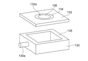
評価6:緻密性判定試験
LDHセパレータがガス不透過性を呈する程の緻密性を有することを確認すべく、緻密性判定試験を以下のとおり行った。まず、図8A及び8Bに示されるように、蓋の無いアクリル容器130と、このアクリル容器130の蓋として機能しうる形状及びサイズのアルミナ治具132とを用意した。アクリル容器130にはその中にガスを供給するためのガス供給口130aが形成されている。また、アルミナ治具132には直径5mmの開口部132aが形成されており、この開口部132aの外周に沿って試料載置用の窪み132bが形成されてなる。アルミナ治具132の窪み132bにエポキシ接着剤134を塗布し、この窪み132bにLDHセパレータ試料136を載置してアルミナ治具132に気密かつ液密に接着させた。そして、LDHセパレータ試料136が接合されたアルミナ治具132を、アクリル容器130の開放部を完全に塞ぐようにシリコーン接着剤138を用いて気密かつ液密にアクリル容器130の上端に接着させて、測定用密閉容器140を得た。この測定用密閉容器140を水槽142に入れ、アクリル容器130のガス供給口130aを圧力計144及び流量計146に接続して、ヘリウムガスをアクリル容器130内に供給可能に構成した。水槽142に水143を入れて測定用密閉容器140を完全に水没させた。このとき、測定用密閉容器140の内部は気密性及び液密性が十分に確保されており、LDHセパレータ試料136の一方の側が測定用密閉容器140の内部空間に露出する一方、LDHセパレータ試料136の他方の側が水槽142内の水に接触している。この状態で、アクリル容器130内にガス供給口130aを介してヘリウムガスを測定用密閉容器140内に導入した。圧力計144及び流量計146を制御してLDHセパレータ試料136内外の差圧が0.5atmとなる(すなわちヘリウムガスに接する側に加わる圧力が反対側に加わる水圧よりも0.5atm高くなる)ようにして、LDHセパレータ試料136から水中にヘリウムガスの泡が発生するか否かを観察した。その結果、ヘリウムガスに起因する泡の発生は観察されなかった場合に、LDHセパレータ試料136はガス不透過性を呈する程に高い緻密性を有するものと判定した。
Evaluation 6 : Denseness determination test In order to confirm that the LDH separator has a denseness enough to exhibit gas impermeableness, a density determination test was conducted as follows. First, as shown in FIGS. 8A and 8B, an
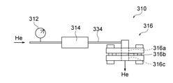
評価7:He透過測定
He透過性の観点からLDHセパレータの緻密性を評価すべくHe透過試験を以下のとおり行った。まず、図9A及び図9Bに示されるHe透過度測定系310を構築した。He透過度測定系310は、Heガスを充填したガスボンベからのHeガスが圧力計312及び流量計314(デジタルフローメーター)を介して試料ホルダ316に供給され、この試料ホルダ316に保持されたLDHセパレータ318の一方の面から他方の面に透過させて排出させるように構成した。
Evaluation 7 : He Permeation Measurement A He permeation test was conducted as follows in order to evaluate the denseness of the LDH separator from the viewpoint of He permeability. First, the He
試料ホルダ316は、ガス供給口316a、密閉空間316b及びガス排出口316cを備えた構造を有するものであり、次のようにして組み立てた。まず、LDHセパレータ318の外周に沿って接着剤322を塗布して、中央に開口部を有する治具324(ABS樹脂製)に取り付けた。この治具324の上端及び下端に密封部材326a,326bとしてブチルゴム製のパッキンを配設し、さらに密封部材326a,326bの外側から、フランジからなる開口部を備えた支持部材328a,328b(PTFE製)で挟持した。こうして、LDHセパレータ318、治具324、密封部材326a及び支持部材328aにより密閉空間316bを区画した。支持部材328a,328bを、ガス排出口316c以外の部分からHeガスの漏れが生じないように、ネジを用いた締結手段330で互いに堅く締め付けた。こうして組み立てられた試料ホルダ316のガス供給口316aに、継手332を介してガス供給管334を接続した。
The
次いで、He透過度測定系310にガス供給管334を経てHeガスを供給し、試料ホルダ316内に保持されたLDHセパレータ318に透過させた。このとき、圧力計312及び流量計314によりガス供給圧と流量をモニタリングした。Heガスの透過を1~30分間行った後、He透過度を算出した。He透過度の算出は、単位時間あたりのHeガスの透過量F(cm3/min)、Heガス透過時にLDHセパレータに加わる差圧P(atm)、及びHeガスが透過する膜面積S(cm2)を用いて、F/(P×S)の式により算出した。Heガスの透過量F(cm3/min)は流量計314から直接読み取った。また、差圧Pは圧力計312から読み取ったゲージ圧を用いた。なお、Heガスは差圧Pが0.05~0.90atmの範囲内となるように供給された。
Next, He gas was supplied to the He
(6)評価結果
評価結果は以下のとおりであった。
‐評価1:得られたXRDプロファイルから、LDHセパレータに含まれる結晶相はLDH(ハイドロタルサイト類化合物)であることが同定された。
‐評価2:LDHセパレータの断面微構造のSEM画像は図10に示されるとおりであった。図10から分かるように、LDHが多孔質基材の厚さ方向の全域にわたって組み込まれていること、すなわち多孔質基材の孔が万遍なくLDHで埋まっていることが観察された。
‐評価3:EDS元素分析の結果、LDHセパレータから、LDH構成元素であるC、Al、Ti及びNiが検出された。すなわち、Al、Ti及びNiは水酸化物基本層の構成元素である一方、CはLDHの中間層を構成する陰イオンであるCO3
2-に対応する。
‐評価4:70℃の水酸化カリウム水溶液に3週間ないし7週間浸漬させた後においても、LDHセパレータの微構造に変化はみられなかった。
‐評価5:LDHセパレータの伝導率は2.0mS/cmであった。
‐評価6:LDHセパレータはガス不透過性を呈する程に高い緻密性を有することが確認された。
‐評価7:LDHセパレータのHe透過度は0.0cm/min・atmであった。
(6) Evaluation results The evaluation results were as follows.
-Evaluation 1: From the obtained XRD profile, it was identified that the crystal phase contained in the LDH separator is LDH (hydrotalcite compound).
-Evaluation 2: The SEM image of the cross-sectional microstructure of the LDH separator was as shown in FIG. As can be seen from FIG. 10, it was observed that LDH was incorporated over the entire area of the porous substrate in the thickness direction, that is, the pores of the porous substrate were evenly filled with LDH.
-Evaluation 3: As a result of EDS elemental analysis, LDH constituent elements C, Al, Ti and Ni were detected from the LDH separator. That is, Al, Ti and Ni are constituent elements of the basic hydroxide layer, while C corresponds to CO 32-2 , which is an anion constituting the intermediate layer of LDH.
-Evaluation 4: No change was observed in the microstructure of the LDH separator even after being immersed in a potassium hydroxide aqueous solution at 70 ° C. for 3 to 7 weeks.
-Evaluation 5: The conductivity of the LDH separator was 2.0 mS / cm.
-Evaluation 6: It was confirmed that the LDH separator has high density so as to exhibit gas impermeableness.
-Evaluation 7: The He permeability of the LDH separator was 0.0 cm / min · atm.
10 亜鉛二次電池
11 電池要素
12 正極板
13 正極活物質層
14a 正極集電体延出部
14b 正極集電板
14c 正極端子
16 負極板
17 負極活物質層
18 負極集電体
18a 負極集電体延出部
18b 負極集電板
18c 負極端子
20 保液部材
22 LDHセパレータ
26 蓋
28 ケース
F 折り目
C 封止された辺
10 Zinc
Claims (9)
亜鉛、酸化亜鉛、亜鉛合金及び亜鉛化合物からなる群から選択される少なくとも1種を含む負極活物質層を含む、複数の負極板と、
高分子材料製の多孔質基材、並びに水酸化物イオン伝導性及びガス不透過性を呈するように前記多孔質基材の孔を塞ぐ層状複水酸化物(LDH)を含む、長尺状のLDHセパレータと、
電解液と、
を含み、前記長尺状のLDHセパレータがつづら折り構造をなしており、該つづら折り構造によって形成される複数の区画に前記正極板及び前記負極板が交互に収容され、それにより前記LDHセパレータを介して前記正極板と前記負極板が互いに隔離され、
前記正極板が空気極である、空気亜鉛二次電池。 With multiple positive electrode plates,
A plurality of negative electrode plates comprising a negative electrode active material layer containing at least one selected from the group consisting of zinc, zinc oxide, zinc alloys and zinc compounds.
Elongated, including a porous substrate made of a polymer material and a layered double hydroxide (LDH) that closes the pores of the porous substrate so as to exhibit hydroxide ion conductivity and gas impermeableness. LDH separator and
With the electrolyte
The long LDH separator has a zigzag structure, and the positive electrode plate and the negative electrode plate are alternately housed in a plurality of compartments formed by the zigzag structure, whereby the LDH separator is interposed therein. The positive electrode plate and the negative electrode plate are separated from each other .
An air zinc secondary battery in which the positive electrode plate is an air electrode .
Priority Applications (1)
| Application Number | Priority Date | Filing Date | Title |
|---|---|---|---|
| JP2018007644A JP6993246B2 (en) | 2018-01-19 | 2018-01-19 | Zinc secondary battery |
Applications Claiming Priority (1)
| Application Number | Priority Date | Filing Date | Title |
|---|---|---|---|
| JP2018007644A JP6993246B2 (en) | 2018-01-19 | 2018-01-19 | Zinc secondary battery |
Publications (2)
| Publication Number | Publication Date |
|---|---|
| JP2019128987A JP2019128987A (en) | 2019-08-01 |
| JP6993246B2 true JP6993246B2 (en) | 2022-02-04 |
Family
ID=67471337
Family Applications (1)
| Application Number | Title | Priority Date | Filing Date |
|---|---|---|---|
| JP2018007644A Active JP6993246B2 (en) | 2018-01-19 | 2018-01-19 | Zinc secondary battery |
Country Status (1)
| Country | Link |
|---|---|
| JP (1) | JP6993246B2 (en) |
Families Citing this family (5)
| Publication number | Priority date | Publication date | Assignee | Title |
|---|---|---|---|---|
| DE112020004526T5 (en) * | 2019-09-25 | 2022-06-09 | Ngk Insulators, Ltd. | Air Electrode/Separator Assembly and Zinc Air Secondary Battery |
| JP6876839B1 (en) * | 2020-02-06 | 2021-05-26 | 日本碍子株式会社 | Electrolyte material and alkaline fuel cell |
| JP7441092B2 (en) * | 2020-03-25 | 2024-02-29 | 日本碍子株式会社 | nickel zinc secondary battery |
| JP2021157944A (en) * | 2020-03-26 | 2021-10-07 | 日本碍子株式会社 | Battery with metal negative electrode |
| JPWO2022190460A1 (en) * | 2021-03-12 | 2022-09-15 |
Citations (3)
| Publication number | Priority date | Publication date | Assignee | Title |
|---|---|---|---|---|
| JP2010199281A (en) | 2009-02-25 | 2010-09-09 | Fuji Heavy Ind Ltd | Electric storage device and method of manufacturing the same |
| JP2016115540A (en) | 2014-12-15 | 2016-06-23 | 日本碍子株式会社 | Secondary battery with hydroxide ion conductive ceramic separator |
| WO2017221988A1 (en) | 2016-06-24 | 2017-12-28 | 日本碍子株式会社 | Functional layer including layered double hydroxide, and composite material |
Family Cites Families (2)
| Publication number | Priority date | Publication date | Assignee | Title |
|---|---|---|---|---|
| JPS60192374U (en) * | 1984-05-30 | 1985-12-20 | 株式会社ユアサコーポレーション | Sealed nickel/zinc storage battery |
| JPH06203819A (en) * | 1992-12-28 | 1994-07-22 | Canon Inc | Alkaline zinc secondary battery |
-
2018
- 2018-01-19 JP JP2018007644A patent/JP6993246B2/en active Active
Patent Citations (3)
| Publication number | Priority date | Publication date | Assignee | Title |
|---|---|---|---|---|
| JP2010199281A (en) | 2009-02-25 | 2010-09-09 | Fuji Heavy Ind Ltd | Electric storage device and method of manufacturing the same |
| JP2016115540A (en) | 2014-12-15 | 2016-06-23 | 日本碍子株式会社 | Secondary battery with hydroxide ion conductive ceramic separator |
| WO2017221988A1 (en) | 2016-06-24 | 2017-12-28 | 日本碍子株式会社 | Functional layer including layered double hydroxide, and composite material |
Also Published As
| Publication number | Publication date |
|---|---|
| JP2019128987A (en) | 2019-08-01 |
Similar Documents
| Publication | Publication Date | Title |
|---|---|---|
| JP6723473B2 (en) | Zinc secondary battery | |
| JP6993422B2 (en) | Negative electrode structure for zinc secondary battery | |
| JP6993246B2 (en) | Zinc secondary battery | |
| JP6784694B2 (en) | Electrode cartridge and zinc secondary battery using it | |
| US10522868B2 (en) | Battery and assembly method therefor | |
| US9692026B2 (en) | Secondary cell using hydroxide-ion-conductive ceramic separator | |
| JP6677860B2 (en) | Method for producing negative electrode structure for zinc secondary battery | |
| JP7095991B2 (en) | Zinc-air battery Cell pack and battery assembly using it | |
| JP6165998B2 (en) | Nickel-zinc battery cell pack and assembled battery using the same | |
| JPWO2018105178A1 (en) | Electrode / separator laminate and nickel zinc battery provided with the same | |
| JP2018026205A (en) | Negative electrode structure and zinc secondary battery including the same | |
| JP6664195B2 (en) | Zinc secondary battery | |
| JP6949142B2 (en) | LDH separator and zinc secondary battery | |
| JP7017445B2 (en) | Negative electrode structure for zinc secondary battery | |
| JP6997019B2 (en) | Zinc secondary battery | |
| WO2019124214A1 (en) | Ldh separator and zinc secondary battery | |
| JP6580379B2 (en) | Nickel zinc battery | |
| US11239489B2 (en) | Zinc secondary battery | |
| JP6864789B2 (en) | LDH separator and zinc secondary battery | |
| WO2019124212A1 (en) | Ldh separator and zinc secondary cell | |
| WO2022113434A1 (en) | Zinc secondary battery | |
| JP7048830B1 (en) | LDH-like compound separator and zinc secondary battery |
Legal Events
| Date | Code | Title | Description |
|---|---|---|---|
| A621 | Written request for application examination |
Free format text: JAPANESE INTERMEDIATE CODE: A621 Effective date: 20201019 |
|
| A977 | Report on retrieval |
Free format text: JAPANESE INTERMEDIATE CODE: A971007 Effective date: 20210831 |
|
| A131 | Notification of reasons for refusal |
Free format text: JAPANESE INTERMEDIATE CODE: A131 Effective date: 20210906 |
|
| A521 | Request for written amendment filed |
Free format text: JAPANESE INTERMEDIATE CODE: A523 Effective date: 20211102 |
|
| TRDD | Decision of grant or rejection written | ||
| A01 | Written decision to grant a patent or to grant a registration (utility model) |
Free format text: JAPANESE INTERMEDIATE CODE: A01 Effective date: 20211202 |
|
| A61 | First payment of annual fees (during grant procedure) |
Free format text: JAPANESE INTERMEDIATE CODE: A61 Effective date: 20211209 |
|
| R150 | Certificate of patent or registration of utility model |
Ref document number: 6993246 Country of ref document: JP Free format text: JAPANESE INTERMEDIATE CODE: R150 |