JP6992046B2 - Lightfield processor system - Google Patents
Lightfield processor system Download PDFInfo
- Publication number
- JP6992046B2 JP6992046B2 JP2019503287A JP2019503287A JP6992046B2 JP 6992046 B2 JP6992046 B2 JP 6992046B2 JP 2019503287 A JP2019503287 A JP 2019503287A JP 2019503287 A JP2019503287 A JP 2019503287A JP 6992046 B2 JP6992046 B2 JP 6992046B2
- Authority
- JP
- Japan
- Prior art keywords
- light field
- eye
- user
- image data
- wearer
- Prior art date
- Legal status (The legal status is an assumption and is not a legal conclusion. Google has not performed a legal analysis and makes no representation as to the accuracy of the status listed.)
- Active
Links
- 238000000034 method Methods 0.000 claims description 287
- 230000003287 optical effect Effects 0.000 claims description 200
- 238000003384 imaging method Methods 0.000 claims description 149
- 238000012360 testing method Methods 0.000 claims description 125
- 230000004075 alteration Effects 0.000 claims description 98
- 208000037265 diseases, disorders, signs and symptoms Diseases 0.000 claims description 34
- 230000003190 augmentative effect Effects 0.000 claims description 31
- 201000009310 astigmatism Diseases 0.000 claims description 27
- 208000001491 myopia Diseases 0.000 claims description 22
- 230000004379 myopia Effects 0.000 claims description 22
- 206010020675 Hypermetropia Diseases 0.000 claims description 20
- 201000006318 hyperopia Diseases 0.000 claims description 20
- 230000004305 hyperopia Effects 0.000 claims description 20
- 210000004087 cornea Anatomy 0.000 claims description 13
- 239000013078 crystal Substances 0.000 claims description 7
- 238000011017 operating method Methods 0.000 claims 4
- 210000001508 eye Anatomy 0.000 description 673
- 230000036541 health Effects 0.000 description 108
- 238000012937 correction Methods 0.000 description 104
- 210000001525 retina Anatomy 0.000 description 101
- 210000003128 head Anatomy 0.000 description 93
- 230000033001 locomotion Effects 0.000 description 91
- 230000004308 accommodation Effects 0.000 description 90
- 238000011282 treatment Methods 0.000 description 78
- 230000000007 visual effect Effects 0.000 description 70
- 210000000695 crystalline len Anatomy 0.000 description 52
- 238000005259 measurement Methods 0.000 description 50
- 230000002207 retinal effect Effects 0.000 description 49
- 230000000875 corresponding effect Effects 0.000 description 46
- 230000011514 reflex Effects 0.000 description 45
- 230000004044 response Effects 0.000 description 42
- 238000004422 calculation algorithm Methods 0.000 description 38
- 230000006870 function Effects 0.000 description 38
- 238000004458 analytical method Methods 0.000 description 33
- 230000008859 change Effects 0.000 description 32
- 238000001514 detection method Methods 0.000 description 32
- 238000012545 processing Methods 0.000 description 32
- 230000008569 process Effects 0.000 description 31
- 208000029257 vision disease Diseases 0.000 description 31
- 230000004393 visual impairment Effects 0.000 description 30
- 238000012544 monitoring process Methods 0.000 description 29
- 210000001747 pupil Anatomy 0.000 description 29
- 230000001965 increasing effect Effects 0.000 description 28
- 230000035945 sensitivity Effects 0.000 description 26
- 230000004438 eyesight Effects 0.000 description 25
- 230000004304 visual acuity Effects 0.000 description 25
- 206010047571 Visual impairment Diseases 0.000 description 24
- 208000035475 disorder Diseases 0.000 description 24
- 201000010041 presbyopia Diseases 0.000 description 23
- 238000009877 rendering Methods 0.000 description 23
- 238000003745 diagnosis Methods 0.000 description 22
- 208000002780 macular degeneration Diseases 0.000 description 21
- 239000003086 colorant Substances 0.000 description 19
- 230000000694 effects Effects 0.000 description 19
- 230000036544 posture Effects 0.000 description 19
- 230000003068 static effect Effects 0.000 description 19
- 230000009471 action Effects 0.000 description 18
- 230000002829 reductive effect Effects 0.000 description 18
- 238000002560 therapeutic procedure Methods 0.000 description 17
- 230000006399 behavior Effects 0.000 description 15
- 230000004424 eye movement Effects 0.000 description 13
- 230000004048 modification Effects 0.000 description 13
- 208000004350 Strabismus Diseases 0.000 description 12
- 238000012986 modification Methods 0.000 description 12
- 201000009487 Amblyopia Diseases 0.000 description 11
- 238000013459 approach Methods 0.000 description 11
- 210000004027 cell Anatomy 0.000 description 10
- 210000003205 muscle Anatomy 0.000 description 10
- 208000014733 refractive error Diseases 0.000 description 10
- 230000005856 abnormality Effects 0.000 description 9
- 230000008901 benefit Effects 0.000 description 9
- 230000006735 deficit Effects 0.000 description 9
- 230000004886 head movement Effects 0.000 description 9
- 230000003993 interaction Effects 0.000 description 9
- 210000004556 brain Anatomy 0.000 description 8
- 238000013500 data storage Methods 0.000 description 8
- 201000010099 disease Diseases 0.000 description 8
- 230000000977 initiatory effect Effects 0.000 description 8
- 230000004256 retinal image Effects 0.000 description 8
- 206010064930 age-related macular degeneration Diseases 0.000 description 7
- 230000004456 color vision Effects 0.000 description 7
- 238000004891 communication Methods 0.000 description 7
- 230000002596 correlated effect Effects 0.000 description 7
- 239000003814 drug Substances 0.000 description 7
- 229940079593 drug Drugs 0.000 description 7
- 238000010801 machine learning Methods 0.000 description 7
- 230000004447 accommodation reflex Effects 0.000 description 6
- 230000001886 ciliary effect Effects 0.000 description 6
- 230000003247 decreasing effect Effects 0.000 description 6
- 230000003292 diminished effect Effects 0.000 description 6
- 238000013507 mapping Methods 0.000 description 6
- 238000013442 quality metrics Methods 0.000 description 6
- 239000000523 sample Substances 0.000 description 6
- 230000001225 therapeutic effect Effects 0.000 description 6
- 208000002111 Eye Abnormalities Diseases 0.000 description 5
- 230000004397 blinking Effects 0.000 description 5
- 230000001447 compensatory effect Effects 0.000 description 5
- 230000002996 emotional effect Effects 0.000 description 5
- 230000006397 emotional response Effects 0.000 description 5
- 238000005516 engineering process Methods 0.000 description 5
- 230000001771 impaired effect Effects 0.000 description 5
- 238000007689 inspection Methods 0.000 description 5
- 230000036961 partial effect Effects 0.000 description 5
- 230000001953 sensory effect Effects 0.000 description 5
- 238000000926 separation method Methods 0.000 description 5
- 230000001052 transient effect Effects 0.000 description 5
- 208000006992 Color Vision Defects Diseases 0.000 description 4
- 241000282412 Homo Species 0.000 description 4
- 206010025421 Macule Diseases 0.000 description 4
- 238000013528 artificial neural network Methods 0.000 description 4
- 208000003464 asthenopia Diseases 0.000 description 4
- 230000002457 bidirectional effect Effects 0.000 description 4
- 230000005540 biological transmission Effects 0.000 description 4
- 230000017531 blood circulation Effects 0.000 description 4
- 201000007254 color blindness Diseases 0.000 description 4
- 230000007423 decrease Effects 0.000 description 4
- 238000010586 diagram Methods 0.000 description 4
- 239000003889 eye drop Substances 0.000 description 4
- 239000004973 liquid crystal related substance Substances 0.000 description 4
- 230000008447 perception Effects 0.000 description 4
- 108091008695 photoreceptors Proteins 0.000 description 4
- 230000009467 reduction Effects 0.000 description 4
- 239000004575 stone Substances 0.000 description 4
- 238000003860 storage Methods 0.000 description 4
- 201000004569 Blindness Diseases 0.000 description 3
- 206010070917 Eccentric fixation Diseases 0.000 description 3
- 206010019233 Headaches Diseases 0.000 description 3
- 230000032683 aging Effects 0.000 description 3
- 206010002537 anisometropia Diseases 0.000 description 3
- 230000009286 beneficial effect Effects 0.000 description 3
- 230000015556 catabolic process Effects 0.000 description 3
- 210000004240 ciliary body Anatomy 0.000 description 3
- 230000001276 controlling effect Effects 0.000 description 3
- 230000006378 damage Effects 0.000 description 3
- 230000007812 deficiency Effects 0.000 description 3
- 238000006731 degradation reaction Methods 0.000 description 3
- 238000002405 diagnostic procedure Methods 0.000 description 3
- 230000002708 enhancing effect Effects 0.000 description 3
- 229940012356 eye drops Drugs 0.000 description 3
- 210000000887 face Anatomy 0.000 description 3
- 239000000835 fiber Substances 0.000 description 3
- 210000000873 fovea centralis Anatomy 0.000 description 3
- 230000004313 glare Effects 0.000 description 3
- 231100000869 headache Toxicity 0.000 description 3
- 230000007246 mechanism Effects 0.000 description 3
- 239000003607 modifier Substances 0.000 description 3
- 230000036651 mood Effects 0.000 description 3
- 238000006386 neutralization reaction Methods 0.000 description 3
- 230000010355 oscillation Effects 0.000 description 3
- 238000003909 pattern recognition Methods 0.000 description 3
- 230000000750 progressive effect Effects 0.000 description 3
- 230000004936 stimulating effect Effects 0.000 description 3
- 230000000638 stimulation Effects 0.000 description 3
- 238000012549 training Methods 0.000 description 3
- 230000009466 transformation Effects 0.000 description 3
- 238000000844 transformation Methods 0.000 description 3
- 241000226585 Antennaria plantaginifolia Species 0.000 description 2
- 208000019901 Anxiety disease Diseases 0.000 description 2
- 206010003805 Autism Diseases 0.000 description 2
- 208000020706 Autistic disease Diseases 0.000 description 2
- 208000002177 Cataract Diseases 0.000 description 2
- 206010010071 Coma Diseases 0.000 description 2
- 206010010904 Convulsion Diseases 0.000 description 2
- 235000004035 Cryptotaenia japonica Nutrition 0.000 description 2
- 208000006550 Mydriasis Diseases 0.000 description 2
- 206010033799 Paralysis Diseases 0.000 description 2
- 102000007641 Trefoil Factors Human genes 0.000 description 2
- 235000015724 Trifolium pratense Nutrition 0.000 description 2
- 230000002159 abnormal effect Effects 0.000 description 2
- 230000004913 activation Effects 0.000 description 2
- 230000003044 adaptive effect Effects 0.000 description 2
- 230000002730 additional effect Effects 0.000 description 2
- 210000003484 anatomy Anatomy 0.000 description 2
- 230000036506 anxiety Effects 0.000 description 2
- 230000036772 blood pressure Effects 0.000 description 2
- 230000036760 body temperature Effects 0.000 description 2
- 210000005252 bulbus oculi Anatomy 0.000 description 2
- 238000006243 chemical reaction Methods 0.000 description 2
- 230000000295 complement effect Effects 0.000 description 2
- 201000000255 cycloplegia Diseases 0.000 description 2
- 230000007850 degeneration Effects 0.000 description 2
- 230000003467 diminishing effect Effects 0.000 description 2
- 238000009826 distribution Methods 0.000 description 2
- 210000000613 ear canal Anatomy 0.000 description 2
- 238000003708 edge detection Methods 0.000 description 2
- 230000001815 facial effect Effects 0.000 description 2
- 230000008713 feedback mechanism Effects 0.000 description 2
- 238000001914 filtration Methods 0.000 description 2
- 230000006872 improvement Effects 0.000 description 2
- 208000014674 injury Diseases 0.000 description 2
- 230000001788 irregular Effects 0.000 description 2
- 230000000670 limiting effect Effects 0.000 description 2
- 235000019557 luminance Nutrition 0.000 description 2
- 238000004519 manufacturing process Methods 0.000 description 2
- 206010029864 nystagmus Diseases 0.000 description 2
- 239000002245 particle Substances 0.000 description 2
- 230000005043 peripheral vision Effects 0.000 description 2
- 239000007787 solid Substances 0.000 description 2
- 238000001228 spectrum Methods 0.000 description 2
- 239000007921 spray Substances 0.000 description 2
- 239000000126 substance Substances 0.000 description 2
- 238000001356 surgical procedure Methods 0.000 description 2
- 208000024891 symptom Diseases 0.000 description 2
- 230000002123 temporal effect Effects 0.000 description 2
- 210000001519 tissue Anatomy 0.000 description 2
- 238000012546 transfer Methods 0.000 description 2
- 230000008733 trauma Effects 0.000 description 2
- 230000001720 vestibular Effects 0.000 description 2
- 238000012800 visualization Methods 0.000 description 2
- 208000024827 Alzheimer disease Diseases 0.000 description 1
- 206010003694 Atrophy Diseases 0.000 description 1
- GVMYEQUFGUYMTP-UHFFFAOYSA-N CC1(C2)C2CCC1 Chemical compound CC1(C2)C2CCC1 GVMYEQUFGUYMTP-UHFFFAOYSA-N 0.000 description 1
- 208000003556 Dry Eye Syndromes Diseases 0.000 description 1
- 206010013774 Dry eye Diseases 0.000 description 1
- 206010013886 Dysaesthesia Diseases 0.000 description 1
- 208000012661 Dyskinesia Diseases 0.000 description 1
- 208000001692 Esotropia Diseases 0.000 description 1
- 201000005538 Exotropia Diseases 0.000 description 1
- 208000031969 Eye Hemorrhage Diseases 0.000 description 1
- WQZGKKKJIJFFOK-GASJEMHNSA-N Glucose Natural products OC[C@H]1OC(O)[C@H](O)[C@@H](O)[C@@H]1O WQZGKKKJIJFFOK-GASJEMHNSA-N 0.000 description 1
- 206010020772 Hypertension Diseases 0.000 description 1
- 206010025412 Macular dystrophy congenital Diseases 0.000 description 1
- 208000019695 Migraine disease Diseases 0.000 description 1
- 206010027603 Migraine headaches Diseases 0.000 description 1
- 206010027646 Miosis Diseases 0.000 description 1
- 206010028813 Nausea Diseases 0.000 description 1
- 208000021384 Obsessive-Compulsive disease Diseases 0.000 description 1
- 206010052087 Oscillopsia Diseases 0.000 description 1
- 206010034960 Photophobia Diseases 0.000 description 1
- 208000037111 Retinal Hemorrhage Diseases 0.000 description 1
- 206010038848 Retinal detachment Diseases 0.000 description 1
- 208000007014 Retinitis pigmentosa Diseases 0.000 description 1
- 206010039729 Scotoma Diseases 0.000 description 1
- 208000003443 Unconsciousness Diseases 0.000 description 1
- 230000002350 accommodative effect Effects 0.000 description 1
- 239000003570 air Substances 0.000 description 1
- 238000003915 air pollution Methods 0.000 description 1
- 239000012080 ambient air Substances 0.000 description 1
- QVGXLLKOCUKJST-UHFFFAOYSA-N atomic oxygen Chemical compound [O] QVGXLLKOCUKJST-UHFFFAOYSA-N 0.000 description 1
- 230000037444 atrophy Effects 0.000 description 1
- 230000007321 biological mechanism Effects 0.000 description 1
- 230000015572 biosynthetic process Effects 0.000 description 1
- 230000000903 blocking effect Effects 0.000 description 1
- 239000008280 blood Substances 0.000 description 1
- 210000004369 blood Anatomy 0.000 description 1
- 230000037237 body shape Effects 0.000 description 1
- 238000005282 brightening Methods 0.000 description 1
- 238000004364 calculation method Methods 0.000 description 1
- 239000000969 carrier Substances 0.000 description 1
- 238000012512 characterization method Methods 0.000 description 1
- 239000003795 chemical substances by application Substances 0.000 description 1
- 239000002642 cobra venom Substances 0.000 description 1
- 230000001427 coherent effect Effects 0.000 description 1
- 238000004883 computer application Methods 0.000 description 1
- 230000008602 contraction Effects 0.000 description 1
- 230000010485 coping Effects 0.000 description 1
- 230000008878 coupling Effects 0.000 description 1
- 238000010168 coupling process Methods 0.000 description 1
- 238000005859 coupling reaction Methods 0.000 description 1
- 208000031513 cyst Diseases 0.000 description 1
- 238000003066 decision tree Methods 0.000 description 1
- 230000003412 degenerative effect Effects 0.000 description 1
- 238000012217 deletion Methods 0.000 description 1
- 230000037430 deletion Effects 0.000 description 1
- 238000000586 desensitisation Methods 0.000 description 1
- 230000006866 deterioration Effects 0.000 description 1
- 230000004392 development of vision Effects 0.000 description 1
- 238000002059 diagnostic imaging Methods 0.000 description 1
- 238000012631 diagnostic technique Methods 0.000 description 1
- 238000006073 displacement reaction Methods 0.000 description 1
- 210000005069 ears Anatomy 0.000 description 1
- 230000002526 effect on cardiovascular system Effects 0.000 description 1
- 230000007613 environmental effect Effects 0.000 description 1
- 231100000317 environmental toxin Toxicity 0.000 description 1
- 238000011156 evaluation Methods 0.000 description 1
- 238000002474 experimental method Methods 0.000 description 1
- 208000027993 eye symptom Diseases 0.000 description 1
- 235000013305 food Nutrition 0.000 description 1
- 210000001061 forehead Anatomy 0.000 description 1
- 230000004927 fusion Effects 0.000 description 1
- 239000007789 gas Substances 0.000 description 1
- 239000008103 glucose Substances 0.000 description 1
- 230000005802 health problem Effects 0.000 description 1
- 230000001976 improved effect Effects 0.000 description 1
- 230000001939 inductive effect Effects 0.000 description 1
- 238000002329 infrared spectrum Methods 0.000 description 1
- 201000000766 irregular astigmatism Diseases 0.000 description 1
- 238000002789 length control Methods 0.000 description 1
- 208000013409 limited attention Diseases 0.000 description 1
- 239000007788 liquid Substances 0.000 description 1
- 230000007774 longterm Effects 0.000 description 1
- 239000000463 material Substances 0.000 description 1
- 229910044991 metal oxide Inorganic materials 0.000 description 1
- 150000004706 metal oxides Chemical class 0.000 description 1
- 230000004459 microsaccades Effects 0.000 description 1
- 230000003547 miosis Effects 0.000 description 1
- 230000002438 mitochondrial effect Effects 0.000 description 1
- 239000000203 mixture Substances 0.000 description 1
- 230000004973 motor coordination Effects 0.000 description 1
- 230000017311 musculoskeletal movement, spinal reflex action Effects 0.000 description 1
- 230000008693 nausea Effects 0.000 description 1
- 230000007433 nerve pathway Effects 0.000 description 1
- 230000006855 networking Effects 0.000 description 1
- 230000008904 neural response Effects 0.000 description 1
- 230000000926 neurological effect Effects 0.000 description 1
- 230000004297 night vision Effects 0.000 description 1
- 235000015097 nutrients Nutrition 0.000 description 1
- 210000001328 optic nerve Anatomy 0.000 description 1
- 238000012014 optical coherence tomography Methods 0.000 description 1
- 238000005457 optimization Methods 0.000 description 1
- 231100000898 oscillopsia Toxicity 0.000 description 1
- 239000001301 oxygen Substances 0.000 description 1
- 229910052760 oxygen Inorganic materials 0.000 description 1
- 208000021090 palsy Diseases 0.000 description 1
- 208000035824 paresthesia Diseases 0.000 description 1
- 230000001575 pathological effect Effects 0.000 description 1
- 230000000737 periodic effect Effects 0.000 description 1
- 230000002093 peripheral effect Effects 0.000 description 1
- 230000002085 persistent effect Effects 0.000 description 1
- 210000000608 photoreceptor cell Anatomy 0.000 description 1
- 230000000704 physical effect Effects 0.000 description 1
- 230000006461 physiological response Effects 0.000 description 1
- 239000000049 pigment Substances 0.000 description 1
- 231100000614 poison Toxicity 0.000 description 1
- 239000002574 poison Substances 0.000 description 1
- 230000010287 polarization Effects 0.000 description 1
- 208000028173 post-traumatic stress disease Diseases 0.000 description 1
- 238000000513 principal component analysis Methods 0.000 description 1
- 230000001902 propagating effect Effects 0.000 description 1
- 238000013139 quantization Methods 0.000 description 1
- 201000009308 regular astigmatism Diseases 0.000 description 1
- 230000001105 regulatory effect Effects 0.000 description 1
- 230000002787 reinforcement Effects 0.000 description 1
- 230000036387 respiratory rate Effects 0.000 description 1
- 230000000284 resting effect Effects 0.000 description 1
- 230000004264 retinal detachment Effects 0.000 description 1
- 230000004262 retinal health Effects 0.000 description 1
- 230000002441 reversible effect Effects 0.000 description 1
- 210000003786 sclera Anatomy 0.000 description 1
- 230000004296 scotopic vision Effects 0.000 description 1
- 208000012672 seasonal affective disease Diseases 0.000 description 1
- 238000005204 segregation Methods 0.000 description 1
- 238000004092 self-diagnosis Methods 0.000 description 1
- 239000004065 semiconductor Substances 0.000 description 1
- 238000007493 shaping process Methods 0.000 description 1
- 238000004088 simulation Methods 0.000 description 1
- 230000005236 sound signal Effects 0.000 description 1
- 230000003595 spectral effect Effects 0.000 description 1
- 238000005728 strengthening Methods 0.000 description 1
- 238000012706 support-vector machine Methods 0.000 description 1
- 210000004243 sweat Anatomy 0.000 description 1
- 238000010408 sweeping Methods 0.000 description 1
- 208000011580 syndromic disease Diseases 0.000 description 1
- 230000026676 system process Effects 0.000 description 1
- 230000008685 targeting Effects 0.000 description 1
- 238000012876 topography Methods 0.000 description 1
- 231100000765 toxin Toxicity 0.000 description 1
- 239000003053 toxin Substances 0.000 description 1
- 108700012359 toxins Proteins 0.000 description 1
- 238000013519 translation Methods 0.000 description 1
- 230000001960 triggered effect Effects 0.000 description 1
- 230000002792 vascular Effects 0.000 description 1
- 230000006444 vascular growth Effects 0.000 description 1
- 238000001429 visible spectrum Methods 0.000 description 1
- 230000009978 visual deterioration Effects 0.000 description 1
- 201000007790 vitelliform macular dystrophy Diseases 0.000 description 1
- 230000003313 weakening effect Effects 0.000 description 1
Images


Classifications
-
- A—HUMAN NECESSITIES
- A61—MEDICAL OR VETERINARY SCIENCE; HYGIENE
- A61B—DIAGNOSIS; SURGERY; IDENTIFICATION
- A61B3/00—Apparatus for testing the eyes; Instruments for examining the eyes
- A61B3/0016—Operational features thereof
- A61B3/0025—Operational features thereof characterised by electronic signal processing, e.g. eye models
-
- A—HUMAN NECESSITIES
- A61—MEDICAL OR VETERINARY SCIENCE; HYGIENE
- A61B—DIAGNOSIS; SURGERY; IDENTIFICATION
- A61B3/00—Apparatus for testing the eyes; Instruments for examining the eyes
-
- A—HUMAN NECESSITIES
- A61—MEDICAL OR VETERINARY SCIENCE; HYGIENE
- A61B—DIAGNOSIS; SURGERY; IDENTIFICATION
- A61B3/00—Apparatus for testing the eyes; Instruments for examining the eyes
- A61B3/0016—Operational features thereof
- A61B3/0041—Operational features thereof characterised by display arrangements
-
- A—HUMAN NECESSITIES
- A61—MEDICAL OR VETERINARY SCIENCE; HYGIENE
- A61B—DIAGNOSIS; SURGERY; IDENTIFICATION
- A61B3/00—Apparatus for testing the eyes; Instruments for examining the eyes
- A61B3/02—Subjective types, i.e. testing apparatus requiring the active assistance of the patient
- A61B3/028—Subjective types, i.e. testing apparatus requiring the active assistance of the patient for testing visual acuity; for determination of refraction, e.g. phoropters
-
- A—HUMAN NECESSITIES
- A61—MEDICAL OR VETERINARY SCIENCE; HYGIENE
- A61B—DIAGNOSIS; SURGERY; IDENTIFICATION
- A61B3/00—Apparatus for testing the eyes; Instruments for examining the eyes
- A61B3/10—Objective types, i.e. instruments for examining the eyes independent of the patients' perceptions or reactions
- A61B3/1015—Objective types, i.e. instruments for examining the eyes independent of the patients' perceptions or reactions for wavefront analysis
-
- A—HUMAN NECESSITIES
- A61—MEDICAL OR VETERINARY SCIENCE; HYGIENE
- A61B—DIAGNOSIS; SURGERY; IDENTIFICATION
- A61B3/00—Apparatus for testing the eyes; Instruments for examining the eyes
- A61B3/10—Objective types, i.e. instruments for examining the eyes independent of the patients' perceptions or reactions
- A61B3/13—Ophthalmic microscopes
-
- A—HUMAN NECESSITIES
- A61—MEDICAL OR VETERINARY SCIENCE; HYGIENE
- A61B—DIAGNOSIS; SURGERY; IDENTIFICATION
- A61B3/00—Apparatus for testing the eyes; Instruments for examining the eyes
- A61B3/10—Objective types, i.e. instruments for examining the eyes independent of the patients' perceptions or reactions
- A61B3/14—Arrangements specially adapted for eye photography
-
- G—PHYSICS
- G02—OPTICS
- G02B—OPTICAL ELEMENTS, SYSTEMS OR APPARATUS
- G02B27/00—Optical systems or apparatus not provided for by any of the groups G02B1/00 - G02B26/00, G02B30/00
- G02B27/01—Head-up displays
- G02B27/017—Head mounted
-
- G—PHYSICS
- G02—OPTICS
- G02B—OPTICAL ELEMENTS, SYSTEMS OR APPARATUS
- G02B27/00—Optical systems or apparatus not provided for by any of the groups G02B1/00 - G02B26/00, G02B30/00
- G02B27/01—Head-up displays
- G02B27/017—Head mounted
- G02B27/0172—Head mounted characterised by optical features
-
- G—PHYSICS
- G02—OPTICS
- G02B—OPTICAL ELEMENTS, SYSTEMS OR APPARATUS
- G02B7/00—Mountings, adjusting means, or light-tight connections, for optical elements
- G02B7/28—Systems for automatic generation of focusing signals
-
- G—PHYSICS
- G02—OPTICS
- G02C—SPECTACLES; SUNGLASSES OR GOGGLES INSOFAR AS THEY HAVE THE SAME FEATURES AS SPECTACLES; CONTACT LENSES
- G02C11/00—Non-optical adjuncts; Attachment thereof
- G02C11/10—Electronic devices other than hearing aids
-
- G—PHYSICS
- G02—OPTICS
- G02C—SPECTACLES; SUNGLASSES OR GOGGLES INSOFAR AS THEY HAVE THE SAME FEATURES AS SPECTACLES; CONTACT LENSES
- G02C7/00—Optical parts
- G02C7/02—Lenses; Lens systems ; Methods of designing lenses
- G02C7/024—Methods of designing ophthalmic lenses
- G02C7/027—Methods of designing ophthalmic lenses considering wearer's parameters
-
- G—PHYSICS
- G06—COMPUTING; CALCULATING OR COUNTING
- G06F—ELECTRIC DIGITAL DATA PROCESSING
- G06F1/00—Details not covered by groups G06F3/00 - G06F13/00 and G06F21/00
- G06F1/04—Generating or distributing clock signals or signals derived directly therefrom
- G06F1/14—Time supervision arrangements, e.g. real time clock
-
- G—PHYSICS
- G06—COMPUTING; CALCULATING OR COUNTING
- G06F—ELECTRIC DIGITAL DATA PROCESSING
- G06F1/00—Details not covered by groups G06F3/00 - G06F13/00 and G06F21/00
- G06F1/16—Constructional details or arrangements
- G06F1/1613—Constructional details or arrangements for portable computers
- G06F1/163—Wearable computers, e.g. on a belt
-
- G—PHYSICS
- G06—COMPUTING; CALCULATING OR COUNTING
- G06F—ELECTRIC DIGITAL DATA PROCESSING
- G06F3/00—Input arrangements for transferring data to be processed into a form capable of being handled by the computer; Output arrangements for transferring data from processing unit to output unit, e.g. interface arrangements
- G06F3/01—Input arrangements or combined input and output arrangements for interaction between user and computer
- G06F3/011—Arrangements for interaction with the human body, e.g. for user immersion in virtual reality
- G06F3/013—Eye tracking input arrangements
-
- G—PHYSICS
- G06—COMPUTING; CALCULATING OR COUNTING
- G06T—IMAGE DATA PROCESSING OR GENERATION, IN GENERAL
- G06T13/00—Animation
- G06T13/20—3D [Three Dimensional] animation
- G06T13/40—3D [Three Dimensional] animation of characters, e.g. humans, animals or virtual beings
-
- G—PHYSICS
- G16—INFORMATION AND COMMUNICATION TECHNOLOGY [ICT] SPECIALLY ADAPTED FOR SPECIFIC APPLICATION FIELDS
- G16H—HEALTHCARE INFORMATICS, i.e. INFORMATION AND COMMUNICATION TECHNOLOGY [ICT] SPECIALLY ADAPTED FOR THE HANDLING OR PROCESSING OF MEDICAL OR HEALTHCARE DATA
- G16H30/00—ICT specially adapted for the handling or processing of medical images
- G16H30/40—ICT specially adapted for the handling or processing of medical images for processing medical images, e.g. editing
-
- G—PHYSICS
- G16—INFORMATION AND COMMUNICATION TECHNOLOGY [ICT] SPECIALLY ADAPTED FOR SPECIFIC APPLICATION FIELDS
- G16H—HEALTHCARE INFORMATICS, i.e. INFORMATION AND COMMUNICATION TECHNOLOGY [ICT] SPECIALLY ADAPTED FOR THE HANDLING OR PROCESSING OF MEDICAL OR HEALTHCARE DATA
- G16H40/00—ICT specially adapted for the management or administration of healthcare resources or facilities; ICT specially adapted for the management or operation of medical equipment or devices
- G16H40/60—ICT specially adapted for the management or administration of healthcare resources or facilities; ICT specially adapted for the management or operation of medical equipment or devices for the operation of medical equipment or devices
- G16H40/63—ICT specially adapted for the management or administration of healthcare resources or facilities; ICT specially adapted for the management or operation of medical equipment or devices for the operation of medical equipment or devices for local operation
-
- G—PHYSICS
- G16—INFORMATION AND COMMUNICATION TECHNOLOGY [ICT] SPECIALLY ADAPTED FOR SPECIFIC APPLICATION FIELDS
- G16H—HEALTHCARE INFORMATICS, i.e. INFORMATION AND COMMUNICATION TECHNOLOGY [ICT] SPECIALLY ADAPTED FOR THE HANDLING OR PROCESSING OF MEDICAL OR HEALTHCARE DATA
- G16H50/00—ICT specially adapted for medical diagnosis, medical simulation or medical data mining; ICT specially adapted for detecting, monitoring or modelling epidemics or pandemics
- G16H50/20—ICT specially adapted for medical diagnosis, medical simulation or medical data mining; ICT specially adapted for detecting, monitoring or modelling epidemics or pandemics for computer-aided diagnosis, e.g. based on medical expert systems
-
- G—PHYSICS
- G02—OPTICS
- G02B—OPTICAL ELEMENTS, SYSTEMS OR APPARATUS
- G02B27/00—Optical systems or apparatus not provided for by any of the groups G02B1/00 - G02B26/00, G02B30/00
- G02B27/01—Head-up displays
- G02B27/0101—Head-up displays characterised by optical features
- G02B2027/011—Head-up displays characterised by optical features comprising device for correcting geometrical aberrations, distortion
-
- G—PHYSICS
- G02—OPTICS
- G02B—OPTICAL ELEMENTS, SYSTEMS OR APPARATUS
- G02B27/00—Optical systems or apparatus not provided for by any of the groups G02B1/00 - G02B26/00, G02B30/00
- G02B27/01—Head-up displays
- G02B27/0101—Head-up displays characterised by optical features
- G02B2027/0132—Head-up displays characterised by optical features comprising binocular systems
-
- G—PHYSICS
- G02—OPTICS
- G02B—OPTICAL ELEMENTS, SYSTEMS OR APPARATUS
- G02B27/00—Optical systems or apparatus not provided for by any of the groups G02B1/00 - G02B26/00, G02B30/00
- G02B27/01—Head-up displays
- G02B27/0101—Head-up displays characterised by optical features
- G02B2027/0138—Head-up displays characterised by optical features comprising image capture systems, e.g. camera
-
- G—PHYSICS
- G02—OPTICS
- G02B—OPTICAL ELEMENTS, SYSTEMS OR APPARATUS
- G02B27/00—Optical systems or apparatus not provided for by any of the groups G02B1/00 - G02B26/00, G02B30/00
- G02B27/01—Head-up displays
- G02B27/0101—Head-up displays characterised by optical features
- G02B2027/014—Head-up displays characterised by optical features comprising information/image processing systems
-
- G—PHYSICS
- G02—OPTICS
- G02B—OPTICAL ELEMENTS, SYSTEMS OR APPARATUS
- G02B27/00—Optical systems or apparatus not provided for by any of the groups G02B1/00 - G02B26/00, G02B30/00
- G02B27/01—Head-up displays
- G02B27/017—Head mounted
- G02B2027/0178—Eyeglass type
-
- G—PHYSICS
- G02—OPTICS
- G02B—OPTICAL ELEMENTS, SYSTEMS OR APPARATUS
- G02B27/00—Optical systems or apparatus not provided for by any of the groups G02B1/00 - G02B26/00, G02B30/00
- G02B27/01—Head-up displays
- G02B27/0179—Display position adjusting means not related to the information to be displayed
- G02B2027/0181—Adaptation to the pilot/driver
-
- G—PHYSICS
- G02—OPTICS
- G02C—SPECTACLES; SUNGLASSES OR GOGGLES INSOFAR AS THEY HAVE THE SAME FEATURES AS SPECTACLES; CONTACT LENSES
- G02C2202/00—Generic optical aspects applicable to one or more of the subgroups of G02C7/00
- G02C2202/22—Correction of higher order and chromatic aberrations, wave front measurement and calculation
Description
(優先権出願)
本願は、2016年7月25日に出願され“LIGHT FIELD PROCESSOR SYSTEM”と題された米国仮特許出願第62/366,524号および2016年12月29日に出願され“LIGHT FIELD PROCESSOR SYSTEM”と題された米国仮特許出願第62/440,286号に対する優先権を主張するものであり、これらの各々の全体の内容は、参照により本明細書中に援用される。
(Priority application)
This application is filed on July 25, 2016 and entitled "LIGHT FIELD PROCESSOR SYSTEM" and US Provisional Patent Application No. 62 / 366,524 and filed on December 29, 2016 as "LIGHT FIELD PROCESSOR SYSTEM". It claims priority to the title US Provisional Patent Application No. 62 / 440,286, the entire contents of each of which are incorporated herein by reference.
本開示は、健康状態および病気を診断、監視、および処置するための種々の方法およびシステムに関する。 The present disclosure relates to various methods and systems for diagnosing, monitoring, and treating health conditions and illnesses.
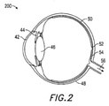
眼科器具および技法は、臨床医によって、眼関連病気を診断および処置するために日常的に使用される。従来の眼科デバイスの実施例は、図1に示される。図示されるデバイスの使用の間、患者は、手技の持続時間全体にわたって、具体的座位に位置付けられ得、これは、典型的には、数秒~数分にわたって続き得る。 Ophthalmic instruments and techniques are routinely used by clinicians to diagnose and treat eye-related illnesses. Examples of conventional ophthalmic devices are shown in FIG. During the use of the illustrated device, the patient may be positioned in a specific sitting position over the duration of the procedure, which can typically last from seconds to minutes.
望ましくないことに、眼科デバイスは、大型で、嵩張り、かつ高価なデバイスである傾向にあり、典型的には、医師のオフィスにおいて排他的に使用される。したがって、患者は、検眼医と予約をとり、任意の診断または処置を受けるために医師を訪問することが要求され得る。これは、多くの患者が、長時間周期にわたって、可能性として、病状が悪化するまで、医師のオフィスに出向くことを遅延させ得る、妨害要因であり得る。悪化した病状は、患者がタイムリーに診断または処置される場合、病状がより容易に寛解されたであろう可能性があるときより、対処するためにさらに徹底的な療法または手技を要求し得る。さらに、大部分の眼科デバイスの大型かつ嵩張る本質は、患者に不快な位置に留めるように強制し、これは、ひいては、誤診および患者エラーのリスクを増加させ得る。 Desirably, ophthalmic devices tend to be large, bulky, and expensive devices, typically used exclusively in the doctor's office. Therefore, the patient may be required to make an appointment with an optometrist and visit the doctor for any diagnosis or treatment. This can be a disturbing factor that can delay many patients from going to the doctor's office over a long cycle, possibly until the condition worsens. Exacerbated medical conditions may require more thorough therapy or procedures to deal with, if the patient is diagnosed or treated in a timely manner, than when the medical condition may have been more easily remitted. .. In addition, the large and bulky nature of most ophthalmic devices forces the patient to stay in an uncomfortable position, which in turn can increase the risk of misdiagnosis and patient error.
故に、上記に説明される難点のうちの1つまたはそれを上回るものに対処する、健康システムの必要がある。 Therefore, there is a need for a health system that addresses one or more of the difficulties described above.
ウェアラブル眼科デバイスが、本明細書に説明される。いくつかの実施形態では、ウェアラブル眼科デバイスは、光をユーザの周囲から受光し、数値的ライトフィールド画像データを生成するように構成される、外向きに面した頭部搭載型ライトフィールドカメラと、数値的ライトフィールド画像データにアクセスし、ユーザの眼に関する光学処方箋を取得し、光学処方箋に基づいて、ある量の正または負の屈折力を数値的ライトフィールド画像データにコンピュータ的に導入し、修正された数値的ライトフィールド画像データを生成するように構成される、ライトフィールドプロセッサと、修正された数値的ライトフィールド画像データに対応する物理的ライトフィールドを生成するように構成される、頭部搭載型ライトフィールドディスプレイとを備える。 Wearable ophthalmic devices are described herein. In some embodiments, the wearable optics device comprises an outward facing head-mounted light field camera configured to receive light from around the user and generate numerical light field image data. Access numerical light field image data, obtain an optical prescription for the user's eye, and computerize and modify a certain amount of positive or negative refractive power into the numerical light field image data based on the optical prescription. Head-mounted, configured to generate a modified numerical light field image data, a light field processor, and a physical light field corresponding to the modified numerical light field image data. Equipped with a type light field display.
ウェアラブル眼科デバイスを使用するための方法もまた、開示される。いくつかの実施形態では、本方法は、ライトフィールドカメラを使用して、光をユーザの周囲から受光し、数値的ライトフィールド画像データを生成するステップと、数値的ライトフィールド画像データにアクセスするステップと、ユーザの眼に関する光学処方箋を取得するステップと、光学処方箋に基づいて、ある量の正または負の屈折力を数値的ライトフィールド画像データにコンピュータ的に導入し、修正された数値的ライトフィールド画像データを生成するステップと、ライトフィールドディスプレイを使用して、修正された数値的ライトフィールド画像データに対応する物理的ライトフィールドを生成するステップとを含む。
本発明は、例えば、以下を提供する。
(項目1)
ウェアラブル眼科デバイスであって、
光をユーザの周囲から受光し、数値的ライトフィールド画像データを生成するように構成される、外向きに面した頭部搭載型ライトフィールドカメラと、
前記数値的ライトフィールド画像データにアクセスし、前記ユーザの眼に関する光学処方箋を取得し、前記光学処方箋に基づいて、ある量の正または負の屈折力を前記数値的ライトフィールド画像データにコンピュータ的に導入し、修正された数値的ライトフィールド画像データを生成するように構成される、ライトフィールドプロセッサと、
前記修正された数値的ライトフィールド画像データに対応する物理的ライトフィールドを生成するように構成される、頭部搭載型ライトフィールドディスプレイと
を備える、デバイス。
(項目2)
前記屈折力は、球面または円柱屈折力を備える、項目1に記載のデバイス。
(項目3)
前記修正された数値的ライトフィールド画像データは、少なくとも部分的に、前記光学処方箋に関して補正される、前記項目のいずれかに記載のデバイス。
(項目4)
前記ライトフィールドプロセッサは、前記数値的ライトフィールド画像データによって表される1つまたはそれを上回る波面を識別し、前記光学処方箋に基づいて、前記1つまたはそれを上回る波面の曲率をコンピュータ的に修正することによって、前記修正された数値的ライトフィールド画像データを生成するように構成される、前記項目のいずれかに記載のデバイス。
(項目5)
前記ライトフィールドプロセッサはさらに、仮想現実または拡張現実画像コンテンツを前記数値的ライトフィールド画像データに追加するように構成される、前記項目のいずれかに記載のデバイス。
(項目6)
前記光学処方箋は、近視に関する処方箋を備える、前記項目のいずれかに記載のデバイス。
(項目7)
前記光学処方箋は、遠視に関する処方箋を備える、前記項目のいずれかに記載のデバイス。
(項目8)
前記光学処方箋は、乱視に関する処方箋を備える、前記項目のいずれかに記載のデバイス。
(項目9)
前記光学処方箋は、前記ユーザの眼の高次収差に関する情報を備える、前記項目のいずれかに記載のデバイス。
(項目10)
前記ライトフィールドカメラは、マイクロレンズの2次元アレイおよび光検出器の対応する2次元アレイを伴う、一体型結像カメラを備える、前記項目のいずれかに記載のデバイス。
(項目11)
前記ライトフィールドディスプレイは、マイクロレンズの2次元アレイおよび光源の対応する2次元アレイを伴う、一体型結像ディスプレイを備える、前記項目のいずれかに記載のデバイス。
(項目12)
前記ライトフィールドディスプレイは、赤外線光を前記ユーザの眼の中に投影し、前記光学処方箋を測定するように構成される、1つまたはそれを上回る赤外線光源を備える、前記項目のいずれかに記載のデバイス。
(項目13)
前記ライトフィールドプロセッサは、前記修正された数値的ライトフィールド画像データをリアルタイムで生成するように構成される、前記項目のいずれかに記載のデバイス。
(項目14)
前記ライトフィールドプロセッサは、前記光学処方箋を生成するように構成される、前記項目のいずれかに記載のデバイス。
(項目15)
前記ライトフィールドプロセッサは、
第1の試験量の正または負の屈折力を前記数値的ライトフィールド画像データにコンピュータ的に導入することと、
前記ユーザから、前記第1の試験量の正または負の屈折力に関するフィードバックを受信することと、
第2の試験量の正または負の屈折力を前記ライトフィールド画像データにコンピュータ的に導入することと
を行うことによって、前記光学処方箋を生成するように構成される、項目14に記載のデバイス。
(項目16)
前記ライトフィールドプロセッサはさらに、前記物理的ライトフィールドの一部として生成される場合、前記ユーザの角膜または水晶体内の障害と相互作用するであろう1つまたはそれを上回る光線を除去することによって、前記修正された数値的ライトフィールド画像データを生成するように構成される、前記項目のいずれかに記載のデバイス。
(項目17)
ウェアラブル眼科デバイスを使用するための方法であって、前記方法は、
修正された数値的ライトフィールド画像データを生成するように、ある量の正または負の屈折力をユーザの周囲の数値的ライトフィールド画像データにコンピュータ的に導入することであって、前記屈折力の量は、前記ユーザに関する光学処方箋に基づく、ことと、
ライトフィールドディスプレイを使用して、前記修正された数値的ライトフィールド画像データに対応する物理的ライトフィールドを生成することと
を含む、方法。
(項目18)
前記修正された数値的ライトフィールド画像データを生成することは、前記数値的ライトフィールド画像データによって表される1つまたはそれを上回る波面を識別し、前記光学処方箋に基づいて、前記1つまたはそれを上回る波面の曲率をコンピュータ的に修正することを含む、項目17に記載の方法。
(項目19)
仮想現実または拡張現実画像コンテンツを前記数値的ライトフィールド画像データに追加することをさらに含む、前記項目のいずれかに記載の方法。
(項目20)
赤外線光を前記ユーザの眼の中に投影させ、前記光学処方箋を測定することをさらに含む、前記項目のいずれかに記載の方法。
(項目21)
前記修正された数値的ライトフィールド画像データをリアルタイムで生成することをさらに含む、前記項目のいずれかに記載の方法。
(項目22)
前記光学処方箋を生成することをさらに含む、前記項目のいずれかに記載の方法。
(項目23)
前記光学処方箋を生成することは、
第1の試験量の正または負の屈折力を前記数値的ライトフィールド画像データにコンピュータ的に導入することと、
前記ユーザから、前記第1の試験量の正または負の屈折力に関するフィードバックを受信することと、
第2の試験量の正または負の屈折力を前記ライトフィールド画像データにコンピュータ的に導入することと
を含む、項目30に記載の方法。
(項目24)
前記物理的ライトフィールドの一部として生成される場合、前記ユーザの角膜または水晶体内の障害と相互作用するであろう1つまたはそれを上回る光線をコンピュータ的に除去することによって、前記修正された数値的ライトフィールド画像データを生成することをさらに含む、前記項目のいずれかに記載の方法。
Methods for using wearable ophthalmic devices are also disclosed. In some embodiments, the method uses a light field camera to receive light from the user's surroundings to generate numerical light field image data, and to access numerical light field image data. And the step of getting an optical prescription for the user's eye, and based on the optical prescription, a certain amount of positive or negative refractive power was computerized into the numerical light field image data and modified numerical light field. It includes a step of generating image data and a step of using a light field display to generate a physical light field corresponding to the modified numerical light field image data.
The present invention provides, for example,:
(Item 1)
A wearable ophthalmic device
An outward-facing head-mounted light field camera that receives light from the user's surroundings and is configured to generate numerical light field image data.
Access the numerical light field image data, obtain an optical prescription for the user's eye, and computerize a certain amount of positive or negative refractive power into the numerical light field image data based on the optical prescription. With a lightfield processor, which is configured to generate modified numerical lightfield image data, introduced and modified.
With a head-mounted lightfield display configured to generate a physical lightfield corresponding to the modified numerical lightfield image data.
The device.
(Item 2)
The device according to
(Item 3)
The device according to any of the above items, wherein the modified numerical light field image data is at least partially corrected with respect to the optical prescription.
(Item 4)
The light field processor identifies one or more wavefronts represented by the numerical light field image data and computer-corrects the curvature of the one or more wavefronts based on the optical prescription. The device according to any of the above items, wherein the device is configured to generate the modified numerical lightfield image data.
(Item 5)
The device according to any of the above items, wherein the light field processor is further configured to add virtual reality or augmented reality image content to the numerical light field image data.
(Item 6)
The device according to any one of the above items, wherein the optical prescription comprises a prescription for myopia.
(Item 7)
The device according to any one of the above items, wherein the optical prescription comprises a prescription for hyperopia.
(Item 8)
The device according to any one of the above items, wherein the optical prescription comprises a prescription for astigmatism.
(Item 9)
The device of any of the above items, wherein the optical prescription comprises information about higher order aberrations of the user's eye.
(Item 10)
The device of any of the above items, wherein the light field camera comprises an integrated imaging camera with a two-dimensional array of microlenses and a corresponding two-dimensional array of photodetectors.
(Item 11)
The device of any of the above items, wherein the light field display comprises an integrated imaging display with a two-dimensional array of microlenses and a corresponding two-dimensional array of light sources.
(Item 12)
The light field display according to any one of the above items, comprising one or more infrared light sources configured to project infrared light into the user's eye and measure the optical prescription. device.
(Item 13)
The device according to any one of the above items, wherein the light field processor is configured to generate the modified numerical light field image data in real time.
(Item 14)
The device according to any of the above items, wherein the light field processor is configured to generate the optical prescription.
(Item 15)
The light field processor is
Computerly introducing the positive or negative refractive power of the first test amount into the numerical light field image data,
Receiving feedback from the user regarding the positive or negative refractive power of the first test dose.
A second test amount of positive or negative refractive power is computerized into the light field image data.
14. The device of item 14, configured to generate the optical prescription by performing.
(Item 16)
The light field processor is further produced by removing one or more light rays that, if generated as part of the physical light field, would interact with the disorder in the user's cornea or crystal body. The device according to any of the above items, configured to generate the modified numerical light field image data.
(Item 17)
A method for using a wearable ophthalmic device, wherein the method is:
Computerly introducing a certain amount of positive or negative power into the numerical light field image data around the user, such as producing modified numerical light field image data, of said refractive power. The amount is based on the optical prescription for the user and
Using a light field display to generate a physical light field corresponding to the modified numerical light field image data.
Including, how.
(Item 18)
Generating the modified numerical light field image data identifies one or more wavefronts represented by the numerical light field image data and, based on the optical prescription, said one or more. 17. The method of item 17, comprising computerically modifying the curvature of the wavefront above.
(Item 19)
The method according to any of the above items, further comprising adding virtual reality or augmented reality image content to the numerical light field image data.
(Item 20)
The method according to any of the above items, further comprising projecting infrared light into the user's eye and measuring the optical prescription.
(Item 21)
The method according to any of the above items, further comprising generating the modified numerical light field image data in real time.
(Item 22)
The method according to any of the above items, further comprising generating the optical prescription.
(Item 23)
Generating the optical prescription is
Computerly introducing the positive or negative refractive power of the first test amount into the numerical light field image data,
Receiving feedback from the user regarding the positive or negative refractive power of the first test dose.
A second test amount of positive or negative refractive power is computerized into the light field image data.
30. The method of
(Item 24)
Corrected by computerically removing one or more rays that, when generated as part of the physical light field, would interact with the disorder in the user's cornea or crystal. The method according to any of the above items, further comprising generating numerical light field image data.
図面は、本明細書に開示されるいくつかの実施例を図示し、本発明を限定するものではない。図は、正確な縮尺で描かれておらず、類似構造または機能の要素は、図全体を通して同様の参照番号によって表されることに留意されたい。 The drawings illustrate some of the embodiments disclosed herein and are not intended to limit the invention. Note that the figures are not drawn to exact scale and elements of similar structure or function are represented by similar reference numbers throughout the figure.
本発明の種々の実施形態は、ユーザにおいて、健康関連診断、監視、および治療法を実施するために使用され得る、ユーザウェアラブル健康システムを実装するためのデバイス、方法、システム、および製造品を対象とする。本発明のある実施形態の種々の目的、特徴、および利点は、発明を実施するための形態、図、および請求項に説明されるが、任意の単一実施形態が、全てのそのような目的、特徴、および利点を含む、または満たすことは、要求されない。 Various embodiments of the invention are directed to devices, methods, systems, and manufactured products for implementing user wearable health systems that may be used to perform health-related diagnostics, monitoring, and treatments in the user. And. The various objectives, features, and advantages of certain embodiments of the invention are described in embodiments, figures, and claims for carrying out the invention, but any single embodiment is all such purpose. , Features, and benefits are not required to be included or met.
種々の実施形態は、図面を参照して詳細に説明されるであろうが、これは、当業者が本発明を実践することを可能にするように、例証的実施例として提供される。着目すべきこととして、以下の図および実施例は、本明細書に説明される本発明の範囲を限定することを意味するものではない。本発明のある要素は、部分的または完全に、公知のコンポーネント(または方法もしくはプロセス)を使用して実装されてもよいが、本発明の理解のために必要なそのような公知のコンポーネント(または方法もしくはプロセス)のそれらの部分のみが、説明され、そのような公知のコンポーネント(または方法もしくはプロセス)の他の部分の詳細な説明は、本発明を曖昧にしないように省略されるであろう。さらに、本発明の実施形態はまた、本明細書で参照されるコンポーネントの現在および将来的公知の均等物を包含する。 Various embodiments will be described in detail with reference to the drawings, which are provided as exemplary embodiments to allow those skilled in the art to practice the invention. Of note, the figures and examples below are not meant to limit the scope of the invention as described herein. Certain elements of the invention may be implemented partially or completely using known components (or methods or processes), such known components (or such known components) that are necessary for the understanding of the invention. Only those parts of the method or process) will be described and detailed description of other parts of such known components (or methods or processes) will be omitted so as not to obscure the invention. .. Further, embodiments of the invention also include current and future known equivalents of the components referred to herein.
ユーザウェアラブル健康システム(例えば、ユーザの眼と相互作用する、ユーザウェアラブル眼科デバイス)を通して、患者の健康異常を診断、処置、および/または監視するための方法ならびにシステムが、本明細書に開示される。1つまたはそれを上回る実施形態では、デバイスは、1つまたはそれを上回る診断または処置計画を実施可能な頭部搭載型システムであってもよい。いくつかの他の実施形態では、デバイスは、定常(例えば、医師のオフィスに定常)であってもよい。1つまたはそれを上回る実施形態では、デバイスは、有利には、健康または眼科目的のために、多くのVR、AR、および/またはMR技法を組み合わせる、仮想現実(VR)、拡張現実(AR)、および/または複合現実(MR)システムであってもよい。VRシステムは、ユーザが体験するためのシミュレートされた環境を作成する。これは、ディスプレイを通して、コンピュータ生成された画像データまたは他の光信号をユーザに提示することによって行われることができる。本画像データは、感覚体験を作成し、これは、ユーザをシミュレートされた環境内に没入させる。VRシナリオは、典型的には、実際の実世界画像データもまた含むのではなく、コンピュータ生成された画像データのみの提示を伴う。ARシステムは、概して、実世界環境をシミュレートされた要素で補完する。例えば、ARシステムは、ユーザに、ディスプレイを介して、周囲実世界環境のビューを提供してもよい。しかしながら、コンピュータ生成された画像データまたは他の光信号もまた、ディスプレイ上に提示され、実世界環境を増強させることができる。本コンピュータ生成された画像データは、実世界環境に状況的に関連する、要素を含むことができる。そのような要素は、シミュレートされたテキスト、画像、オブジェクト等を含むことができる。シミュレートされた要素は、多くの場合、リアルタイムで双方向であることができる。MRシナリオは、ARシナリオの1つのタイプであって、典型的には、自然世界の中に統合され、それに応答する、仮想オブジェクトを伴う。例えば、MRシナリオでは、AR画像コンテンツは、実世界内のオブジェクトと相互作用するように知覚されるような方法で提示されてもよい。 Methods and systems for diagnosing, treating, and / or monitoring a patient's health abnormalities through a user wearable health system (eg, a user wearable ophthalmic device that interacts with the user's eye) are disclosed herein. .. In one or more embodiments, the device may be a head-mounted system capable of performing one or more diagnostic or treatment plans. In some other embodiments, the device may be stationary (eg, stationary in a physician's office). In one or more embodiments, the device advantageously combines many VR, AR, and / or MR techniques for health or ophthalmic purposes, virtual reality (VR), augmented reality (AR). , And / or may be a mixed reality (MR) system. The VR system creates a simulated environment for the user to experience. This can be done by presenting the user with computer-generated image data or other optical signals through the display. The image data creates a sensory experience that immerses the user in a simulated environment. VR scenarios typically involve the presentation of computer-generated image data only, rather than also including real-world image data. AR systems generally complement the real-world environment with simulated elements. For example, the AR system may provide the user with a view of the surrounding real world environment via the display. However, computer-generated image data or other optical signals can also be presented on the display to enhance the real-world environment. The computer-generated image data may contain elements that are contextually relevant to the real world environment. Such elements can include simulated text, images, objects, and the like. Simulated elements can often be bidirectional in real time. MR scenarios are a type of AR scenario, typically with virtual objects that are integrated into and respond to in the natural world. For example, in an MR scenario, AR image content may be presented in such a way that it is perceived to interact with objects in the real world.
いくつかの他の実施形態では、臨床医は、診断および/またはシミュレーションならびに訓練の目的のために、デバイスを装着してもよい。以下に説明される種々の実施形態は、ARシステムに関連して健康システムの新しいパラダイムについて議論するが、本明細書に開示される技法は、任意の既存および/または公知のARシステムから独立して使用されてもよいことを理解されたい。したがって、以下に議論される実施例は、例示的目的のためにすぎず、ARシステムに限定されるように読まれるべきではない。 In some other embodiments, the clinician may wear the device for diagnostic and / or simulation and training purposes. Although the various embodiments described below discuss new paradigms for health systems in relation to AR systems, the techniques disclosed herein are independent of any existing and / or known AR systems. Please understand that it may be used. Therefore, the examples discussed below are for illustrative purposes only and should not be read as limited to AR systems.
前述のように、本発明の実施形態は、眼科器具等のユーザウェアラブル健康診断または健康療法システム(概して、本明細書では、健康システムと称される)が、患者によって装着され、種々の健康関連(例えば、眼関連)病気に特有の1つまたはそれを上回る用途に伴ってプログラムされ得る、新しいパラダイムを提示する。いくつかの実施形態では、診断および/または処置は、光学デバイス、機械的構造、処理アルゴリズム、または前述の任意の組み合わせによって提供されてもよい。いくつかの他の実施形態では、患者装着型健康システムはさらに、増強された処置または診断目的のために、感知および/または刺激能力を伴ってもよい。いくつかの実施形態では、頭部装着型拡張現実システムは、種々の健康関連(例えば、眼科)測定、査定、診断、または処置を提供するために使用されてもよい。 As mentioned above, in embodiments of the present invention, a user-wearable health diagnosis or health therapy system (generally referred to herein as a health system), such as an ophthalmic device, is worn by the patient and is various health related. It presents a new paradigm that can be programmed with one or more uses specific to a disease (eg, eye-related). In some embodiments, the diagnosis and / or treatment may be provided by an optical device, mechanical structure, processing algorithm, or any combination described above. In some other embodiments, the patient-worn health system may further be associated with sensing and / or stimulating capacity for enhanced treatment or diagnostic purposes. In some embodiments, the head-mounted augmented reality system may be used to provide a variety of health-related (eg, ophthalmic) measurements, assessments, diagnoses, or treatments.
頭部搭載型拡張現実ディスプレイシステムがユーザの眼と相互作用することを前提として、多くの用途が、眼関連診断および治療法のために想定され得る。さらに、非眼診断および治療法における多くの他の用途も、同様に想定され得る。故に、本明細書に提示される本開示は、眼の診断、監視、および/または処置に限定されない。本明細書に開示される実施形態はまた、限定ではないが、ユーザの心血管および神経的健康を含む、ユーザの他のエリアの健康を診断、監視、および/または処置するために適用されてもよい。 Given that the head-mounted augmented reality display system interacts with the user's eye, many applications can be envisioned for eye-related diagnostics and treatments. In addition, many other uses in non-ocular diagnosis and treatment can be envisioned as well. Therefore, the disclosure presented herein is not limited to eye diagnosis, monitoring, and / or treatment. The embodiments disclosed herein are also applied to diagnose, monitor, and / or treat the health of other areas of the user, including, but not limited to, the cardiovascular and neurological health of the user. May be good.
健康システムの多くの実施形態は、種々の眼関連および他の病気に関連して議論されるであろう。健康システムの種々の実施形態の詳述に先立って、ヒトの眼の生物学的機構が、患者に影響を及ぼし得る一般的病気に対する状況を提供するために、以下に簡単に議論されるであろう。 Many embodiments of the health system will be discussed in connection with various eye-related and other illnesses. Prior to detailing the various embodiments of the health system, the biological mechanisms of the human eye will be briefly discussed below to provide a situation for common illnesses that can affect patients. Let's go.
図2を参照すると、ヒトの眼の簡略化された断面図が、描写されており、角膜42、虹彩44、レンズ、すなわち、「水晶体」46、強膜48、脈絡膜層50、黄斑52、網膜54、および脳への視神経経路56を特徴とする。黄斑は、網膜の中心であって、これは、中程度の詳細を見るために利用される。黄斑の中心には、「中心窩」と称される、網膜の一部があり、これは、最も微細な詳細を見るために利用され、網膜の任意の他の部分より多くの光受容体(視度あたり約120錐体)を含有する。ヒトの視覚系は、受動センサタイプのシステムではない。すなわち、環境を能動的に走査するように構成される。画像を捕捉するためのフラットベッドスキャナの使用または紙から点字を読み取る指の使用に幾分類似する様式において、眼の光受容体は、刺激の一定状態に一定に応答するのではなく、刺激の変化に応答して発火する。したがって、運動が、光受容体情報を脳に提示するために要求される。実際、眼の筋肉を麻痺さるために利用されている、コブラ毒等の物質を用いた実験において、ヒト対象が、その眼が開放された状態で位置付けられ、静的場面を眼の毒誘発麻痺状態で視認する場合、盲目状態を被るであろうことが示されている。言い換えると、刺激の変化がない場合、光受容体は、入力を脳に提供せず、盲目状態を被る。これは、正常なヒトの眼が、「マイクロサッケード」と呼ばれる側方運動において、往復して移動する、すなわち、微動することが観察されていることの少なくとも1つの理由であると考えられる。
Referring to FIG. 2, a simplified cross-sectional view of the human eye is depicted, including the
前述のように、網膜の中心窩は、視細胞の最大密度を含有し、ヒトは、典型的には、その視野全体を通して高分解能可視化能力を持つ知覚を有するが、概して、実際には、中心窩で直近で捕捉された高分解能情報の持続的記憶とともに、何度も機械的に掃引している小高分解能中心のみを有する。若干類似する様式において、眼の焦点距離制御機構(毛様体弛緩が、毛様体結合線維の緊張を生じさせ、より離れた距離で視認するために使用されるより長い焦点距離のためにレンズを平坦化させる一方、毛様体収縮が、毛様体結合線維の弛緩を生じさせ、より短い処理で視認するために使用されるより短い焦点距離のためにより丸い幾何学形状をとることを可能にする様式で、水晶体に動作可能に結合される毛様筋)は、標的焦点距離の近側および遠側の両方に、少量の「光屈折ぼけ」と呼ばれるものを周期的に誘発するために、約1/4~1/2ジオプタだけ往復微動する。これは、遠近調節を常に補正し、固視されたオブジェクトの網膜画像をほぼ合焦させて保つことに役立つ、周期的負のフィードバックとして、脳の遠近調節制御機能性によって利用される。 As mentioned above, the fovea centralis of the retina contains the maximum density of photoreceptor cells, and humans typically have a perception with high resolution visualization capability throughout their field of view, but in general, in practice, the center. It has only a small high-resolution center that has been mechanically swept many times, with a persistent memory of the high-resolution information most recently captured in the fovea. In a slightly similar fashion, the focal length control mechanism of the eye, the lens for longer focal lengths where ciliary relaxation causes tension in the ciliary connecting fibers and is used for visual recognition at greater distances. While flattening the ciliary body contraction causes relaxation of the ciliary body connecting fibers, it is possible to take a more rounded geometric shape due to the shorter focal length used for visual recognition in shorter processes. The ciliary muscle, which is operably connected to the crystalline body in the manner of the ciliary body), periodically induces a small amount of what is called "light refraction blur" both near and far from the target focal length. , Reciprocating fine movement by about 1/4 to 1/2 diopter. This is utilized by the accommodation control functionality of the brain as periodic negative feedback that helps to constantly correct the accommodation and keep the retinal image of the fixed object nearly in focus.
脳の可視化中枢はまた、両眼およびその構成要素の相互に対する運動から有益な知覚情報を得る。相互に対する両眼の輻輳・開散(vergence)運動(すなわち、眼の視線を輻輳させ、オブジェクトを固視するための相互に向かって、またはそこから離れる、瞳孔の回転移動)は、眼のレンズの合焦(または「遠近調節(accommodation)」)と密接に関連付けられる。正常状態下では、眼のレンズの焦点を変化させる、すなわち、眼を遠近調節させ、異なる距離におけるオブジェクトに合焦させることは、「遠近調節-輻輳・開散運動反射」として知られる関係下、自動的に、同一距離までの輻輳・開散運動における整合変化を生じさせるであろう。同様に、輻輳・開散運動の変化は、正常状態下では、遠近調節の整合変化も誘起するであろう。本反射に逆らう作用は、(従来の立体視ARまたはVR構成のいくつかにおけるように)眼疲労、頭痛、または他の形態の不快感をユーザにもたらすことが知られている。 The visualization center of the brain also obtains useful perceptual information from the mutual movement of both eyes and their components. The accommodation and accommodation movements of both eyes with respect to each other (that is, the rotational movement of the pupil toward or away from each other to congest the line of sight of the eye and fix the object) are the lenses of the eye. Is closely associated with focusing (or "accommodation"). Under normal conditions, changing the focus of the lens of the eye, that is, accommodating the eye and focusing on objects at different distances, is a relationship known as "accommodation-convergence / divergent motion reflex". It will automatically cause a matching change in the convergence / divergence movement up to the same distance. Similarly, changes in convergence and divergence movements will also induce accommodation changes in accommodation under normal conditions. The action against this reflex is known to cause eye fatigue, headache, or other forms of discomfort to the user (as in some conventional stereoscopic AR or VR configurations).
眼を格納する、頭部の移動もまた、オブジェクトの可視化に重要な影響を及ぼす。ヒトは、その頭部を移動させ、その周囲の世界を可視化する。多くの場合、着目オブジェクトに対して、非常に一定した頭部の再位置付けおよび再配向の状態にある。さらに、大部分の人々は、その眼視線が、特定のオブジェクトに合焦させるために中心から約20度を上回って移動する必要があるとき、その頭部を移動させることを好む(すなわち、人々は、典型的には、「眼の隅から」物を見ることを好まない)。ヒトはまた、典型的には、音に連動してその頭部を走査または移動させ、オーディオ信号捕捉を改善し、頭部に対する耳の幾何学形状を利用する。ヒトの視覚系は、頭部の運動および眼の輻輳・開散運動距離の関数として、異なる距離におけるオブジェクトの相対運動に関連する、「頭部運動視差」と呼ばれるものから優れた深度のキューを得る(すなわち、人物が、その頭部を横方向に移動させ、オブジェクトへの固視を維持する場合、そのオブジェクトからより遠いアイテムは、頭部と同一方向に移動するように現れる一方、そのオブジェクトの正面のアイテムは、頭部運動と反対に移動するように現れるであろう。これらは、人物に対する環境内の空間的場所に位置するものの場所に関する非常に顕著なキューであって、おそらく、立体視と同等に優れている)。頭部運動はまた、当然ながら、オブジェクトを見渡すためにも利用される。 The movement of the head, which houses the eyes, also has an important effect on the visualization of the object. Humans move their heads and visualize the world around them. In many cases, the head is in a very constant repositioning and reorientation state with respect to the object of interest. In addition, most people prefer to move their head when their line of sight needs to move more than about 20 degrees from the center to focus on a particular object (ie, people). Typically do not like to see things "from the corner of the eye"). Humans also typically scan or move their heads in conjunction with sound to improve audio signal capture and utilize the geometry of the ears with respect to the head. The human visual system provides excellent depth cues from what is called "head motion disparity", which is associated with the relative motion of objects at different distances as a function of head motion and eye congestion / divergence motion distance. Gain (ie, if a person moves his head laterally and maintains his gaze on an object, items farther from the object will appear to move in the same direction as the head, while the object. The frontal items of the will appear to move in the opposite direction of the head movement. These are very prominent cues about the location of what is located in a spatial location in the environment for the person, and is probably a solid. As good as vision). Head movements are, of course, also used to look over objects.
さらに、頭部および眼の運動は、頭部回転の間、網膜に対する画像情報を安定化させ、したがって、オブジェクト画像情報を網膜のほぼ中心に保つ、「前庭眼反射」と呼ばれるものと協調される。頭部の回転に応答して、眼は、反射的かつ比例的に反対方向に回転され、オブジェクトに対する安定した固定状態を維持する。本補償関係の結果として、多くのヒトは、その頭部を往復して振動させながら、本を読むことができる(興味深いことに、本が、頭部がほぼ定常のまま、同一速度で往復してめくられる場合、同じことは、概して、当てはまらない。すなわち、人は、めくられている本を読むことができない可能性が高い。前庭眼反射は、頭部および眼の運動協調のうちの1つであって、概して、手の運動のために発達されていない)。本パラダイムは、ユーザの頭部運動が、比較的に直接、眼の運動と関連付けられ得るため、患者装着型健康システムのために重要であり得、システムは、好ましくは、本関係と協働する準備ができたものとなるであろう。したがって、患者装着型または定常ディスプレイベースの健康システムを設計するとき、ヒトの眼の特性、時として、限界が、好ましくは、それらにストレスを課すのではなく、眼の自然機構と協働する、有意義な仮想コンテンツを提供するために考慮される。さらに、ARディスプレイシステムの健康関連用途の状況では、これは、本明細書に開示されるような種々の利点を提供することができる。前述のように、健康システムのディスプレイは、ARシステムから独立して実装されてもよいが、以下の多くの実施形態は、例証的目的のためだけに、ARシステムと関連して説明される。 In addition, head and eye movements are coordinated with what is called the "vestibular eye reflex", which stabilizes the image information to the retina during head rotation and thus keeps the object image information approximately centered on the retina. .. In response to head rotation, the eyes are reflexively and proportionally rotated in opposite directions, maintaining a stable fixation to the object. As a result of this compensation relationship, many humans can read a book while reciprocating and vibrating its head (interestingly, the book reciprocates at the same speed with its head almost stationary. The same is generally not the case when flipped, that is, a person is likely unable to read a flipped book. The vestibular eye reflex is one of head and eye motor coordination. However, it is generally not developed for hand movements). This paradigm can be important for patient-worn health systems, as the user's head movements can be relatively directly associated with eye movements, and the system preferably works with this relationship. It will be ready. Therefore, when designing patient-worn or stationary display-based health systems, the characteristics of the human eye, sometimes the limitations, preferably work with the natural mechanisms of the eye rather than stressing them. Considered to provide meaningful virtual content. Moreover, in the context of health-related applications for AR display systems, this can provide various benefits as disclosed herein. As mentioned above, the display of the health system may be implemented independently of the AR system, but many of the following embodiments will be described in connection with the AR system for illustrative purposes only.
ここで図3A-3Dを参照すると、いくつかの一般的コンポーネントオプションが、図示される。図3A-3Dの実施形態は、頭部搭載型ディスプレイを図示するが、同一コンポーネントは、いくつかの実施形態では、定常健康システム内にも同様に組み込まれてもよいことを理解されたい。 Here, with reference to FIGS. 3A-3D, some common component options are illustrated. Although the embodiment of FIG. 3A-3D illustrates a head-mounted display, it should be appreciated that the same components may be incorporated into the steady health system as well in some embodiments.
図3Aに示されるように、ユーザ60は、ユーザの眼の正面に位置付けられるディスプレイシステム62に結合されるフレーム64構造を含む、患者装着型眼科デバイスを装着して描写される。フレーム64は、健康システムの用途に応じて、いくつかの眼科特有の測定サブシステムに結合されてもよい。いくつかの実施形態は、1つまたはそれを上回る眼科用途のために構築されてもよく、他の実施形態は、同様に眼科用途に対応可能な一般的ARシステムであってもよい。いずれの場合も、以下の開示は、眼科計器および/または処置のために使用される、健康システムまたはARシステムの可能性として考えられるコンポーネントを説明する。
As shown in FIG. 3A, the
1つまたはそれを上回る実施形態では、健康システムは、患者、すなわち、ユーザに装着される。いくつかの他の実施形態では、健康システムは、別の人物(例えば、医師または臨床医)によって装着されてもよく、システムの装着者ではない患者において、診断試験および/または処置プロトコルのセットを実施するために使用されてもよい。以下の用途のいずれも、患者において診断試験、処置プロトコル、および/または監視(リアルタイムまたは縦断的に)を行うためにも同様に、他の人物によって装着される健康システムのために使用されてもよいことを理解されたい。 In one or more embodiments, the health system is worn by the patient, i.e., the user. In some other embodiments, the health system may be worn by another person (eg, a doctor or clinician), and in a patient who is not the wearer of the system, a set of diagnostic tests and / or treatment protocols. It may be used to carry out. Any of the following uses may be used for diagnostic tests, treatment protocols, and / or monitoring (real-time or longitudinal) in patients as well as for health systems worn by others. Please understand that it is good.
スピーカ66が、描写される構成では、フレーム64に結合され、ユーザの外耳道に隣接して位置付けられてもよい。(一実施形態では、別のスピーカ(図示せず)が、ステレオ/調節可能音制御を提供するために、ユーザの他の外耳道に隣接して位置付けられる。)マイクロホン55もまた、フレームに結合され、ユーザまたは周囲環境からの音を検出してもよい。いくつかの実施形態では、別のマイクロホン(図示せず)も、提供されてもよい(例えば、ユーザの右手側において、フレーム64に結合される)。1つまたはそれを上回る実施形態では、健康システムは、有線導線または無線コネクティビティ68等によって、レーム64に固定して取り付けられる、図3Bの実施形態に示されるように、ヘルメットまたは帽子80に固定して取り付けられる、ヘッドホン内に内蔵される、図3Cの実施形態に示されるように、リュック式構成において、ユーザ60の胴体82に除去可能に取り付けられる、または図3Dの実施形態に示されるように、ベルト結合式構成において、ユーザ60の腰部84に除去可能に取り付けられる等、種々の構成において搭載され得る、ローカル処理およびデータモジュール70に動作可能に結合される、ディスプレイ62を有してもよい。
The
ローカル処理およびデータモジュール70は、屈折力効率的プロセッサまたはコントローラと、フラッシュメモリ等のデジタルメモリとを含んでもよく、両方とも、a)画像捕捉デバイス(カメラ等)、マイクロホン、慣性測定ユニット、加速度計、コンパス、GPSユニット、無線デバイス、および/またはジャイロスコープ等のフレーム64に動作可能に結合され得る、センサから捕捉される、および/またはb)可能性として、処理または読出後、ディスプレイ62への通過のために、遠隔処理モジュール72および/または遠隔データリポジトリ74を使用して入手および/または処理される、データの処理、キャッシュ、および記憶を補助するために利用されてもよい。ローカル処理およびデータモジュール70は、これらの遠隔モジュール72、74が、相互に動作可能に結合され、ローカル処理およびデータモジュール70へのリソースとして利用可能であるように、有線または無線通信リンク76、78等を介して、遠隔処理モジュール72および遠隔データリポジトリ74に動作可能に結合されてもよい。
The local processing and
いくつかの実施形態では、遠隔処理モジュール72は、データおよび/または画像情報を分析および処理するように構成される、1つまたはそれを上回る比較的に強力なプロセッサまたはコントローラを含んでもよい。いくつかの実施形態では、遠隔データリポジトリ74は、比較的に大規模デジタルデータ記憶設備を含んでもよく、これは、インターネットまたは「クラウド」リソース構成における他のネットワーキング構成を通して利用可能であってもよい。いくつかの実施形態では、全てのデータは、記憶され、全ての算出は、ローカル処理およびデータモジュールにおいて実施され、遠隔モジュールからの完全に自律的使用を可能にする。
In some embodiments, the
有利には、図3A-3Dに説明されるものに類似する、健康システム(または眼科用途を有する、ARシステム)は、ユーザの眼および頭部への一意のアクセスを提供する。健康システムが、ユーザの眼と相互作用し、ユーザが、3D仮想コンテンツを知覚し、多くの実施形態では、ユーザの眼に関連する種々のバイオメトリック(例えば、眼輻輳・開散運動、眼運動、網膜構造、前および後眼幾何学形状、眼移動のパターン等)を追跡することを可能にすることを前提として、得られた追跡されたデータは、有利には、本明細書にさらに詳細に説明されるように、健康関連用途において使用されてもよい。本ユーザの眼へのかつてないアクセスは、種々の健康用途の実装に有益である。健康異常のタイプに応じて、健康システムは、ユーザの眼の結像、感知(測定を含む)、および/またはそこへの刺激を提供し、病気を診断および/または処置するように構成されてもよい。 Advantageously, a health system (or an AR system with an ophthalmic use) similar to that described in FIGS. 3A-3D provides unique access to the user's eyes and head. The health system interacts with the user's eye, the user perceives 3D virtual content, and in many embodiments, various biometrics associated with the user's eye (eg, eye congestion / divergence movement, eye movement). , Retinal structure, anterior and posterior ocular geometry, patterns of eye movement, etc.), the tracked data obtained is advantageously further detailed herein. It may be used in health-related applications as described in. The user's unprecedented access to the eyes is beneficial for the implementation of various health uses. Depending on the type of health disorder, the health system is configured to provide imaging, sensing (including measurements), and / or stimulation to the user's eye to diagnose and / or treat the disease. May be good.
1つまたはそれを上回る実施形態では、拡張現実ディスプレイシステムは、患者装着型、すなわち、ユーザ装着型、眼科デバイスとして使用されてもよい。眼科計器は、臨床医によって、患者の眼を視認および検査し、医療手技を実行する、および/またはユーザの眼に試験または療法を実施するために使用される。従来、眼科デバイスは、大型かつ嵩張る定常デバイスを有しており、多くの場合、患者が医師のオフィスを訪れることを要求し、そこで臨床医または医師は、患者に眼関連試験を実施する。典型的には、患者は、臨床医が一連の試験を完了するまで、眼科計器デバイス(例えば、眼科デバイスの顎置コンポーネント上に顎を載せ、頭部を正面に向けた状態等)に拘束される。したがって、現在のアプローチは、いくつかの限界を有する。 In one or more embodiments, the augmented reality display system may be used as a patient-mounted, i.e., user-mounted, ophthalmic device. Ophthalmic instruments are used by clinicians to visually and inspect a patient's eye, perform medical procedures, and / or perform tests or therapies on the user's eye. Traditionally, ophthalmic devices have large and bulky stationary devices that often require the patient to visit the doctor's office, where the clinician or physician conducts eye-related trials on the patient. Typically, the patient is restrained in an ophthalmic instrument device (eg, with the jaw resting on the jaw-mounted component of the ophthalmic device with the head facing forward) until the clinician completes a series of trials. To. Therefore, the current approach has some limitations.
試験のための重くかつ嵩張るデバイスの使用に加え、従来のアプローチは、医師が監督することを要求し、患者は、さらなる試験/進行度評価のために、臨床医のオフィスに繰り返し戻る必要があり得、かつ長時間周期にわたって、不快なまたは制限的位置に留まる必要があり得る。さらに、患者が眼科デバイスに暴露される短持続時間を前提として、患者を診断または処置するために、臨床医が収集可能なデータの量に限界が存在する。従来のアプローチは、ユーザの挙動およびユーザの配向の動的変化を考慮しない。従来のアプローチ下で実施される多くの試験は、ユーザが特定の通常静的である位置に制約されることを要求する。しかしながら、ユーザが、例えば、視野試験を受けており、限定された注意期間を有する場合、彼らは、その頭部および眼を移動させ、それによって、雑音を生成し、可能性として、不正確な試験結果を生じさせ得る。加えて、従来のアプローチは、人を引きつけるもの、関心を引くもの、または双方向なものではない。 In addition to the use of heavy and bulky devices for testing, traditional approaches require physician supervision and patients must repeatedly return to the clinician's office for further study / progress assessment. Gain and may need to remain in an unpleasant or restrictive position over a long cycle. In addition, there is a limit to the amount of data a clinician can collect to diagnose or treat a patient, given the short duration of exposure of the patient to the ophthalmic device. The traditional approach does not consider dynamic changes in user behavior and user orientation. Many tests performed under the traditional approach require that the user be constrained to a particular normally static location. However, if the user is undergoing a visual field test, for example, and has a limited attention period, they move their head and eyes, thereby producing noise and potentially inaccuracies. Can give rise to test results. In addition, traditional approaches are not attractive, interesting, or bidirectional.
1つまたはそれを上回る実施形態では、図3A-3Dに示されるものに類似する頭部装着型健康(例えば、眼科)デバイスは、患者によって、データを追跡し、1つまたはそれを上回る眼関連病気を識別および補正し、および/または他の健康問題を防止することに役立てるために使用されてもよい。1つまたはそれを上回る実施形態では、ARディスプレイシステムは、頭部装着型健康(例えば、眼科)デバイスとして使用されてもよい。以下に説明されるいくつかの実施形態は、頭部装着型実施形態において実装されてもよい一方、他の実施形態は、定常デバイスにおいて実装されてもよいことを理解されたい。さらに、いくつかの実施形態は、AR技術を利用して、医師監督を伴う(例えば、医療安全上の懸念、規制上の懸念等のために)、診断、監視、および/または処置のためのシステムおよび方法を実装してもよい一方、他の実施形態は、頭部装着型健康デバイスまたはARデバイスを通した自己診断および/または監視のために実装されてもよい、または本明細書に説明されるように、特定の病気のための処置プロトコルの一部として実装されてもよい。例証目的のために、本開示は、主に、頭部装着型健康デバイス、特に、ARデバイスに焦点を当てるであろうが、同一原理は、非頭部装着型実施形態にも同様に適用されてもよいことを理解されたい。 In one or more embodiments, a head-worn health (eg, ophthalmic) device similar to that shown in FIG. 3A-3D tracks data by the patient and is one or more eye-related. It may be used to help identify and correct illness and / or prevent other health problems. In one or more embodiments, the AR display system may be used as a head-worn health (eg, ophthalmic) device. It should be appreciated that some embodiments described below may be implemented in head-mounted embodiments, while other embodiments may be implemented in stationary devices. In addition, some embodiments utilize AR technology and involve physician supervision (eg, for medical safety concerns, regulatory concerns, etc.) for diagnosis, monitoring, and / or treatment. While the system and method may be implemented, other embodiments may be implemented for self-diagnosis and / or monitoring through a head-worn health device or AR device, or described herein. As such, it may be implemented as part of a treatment protocol for a particular disease. For illustration purposes, this disclosure will focus primarily on head-mounted health devices, in particular AR devices, but the same principles apply to non-head-mounted embodiments as well. Please understand that it is okay.
1つまたはそれを上回る実施形態では、ARディスプレイデバイスは、患者装着型健康デバイスとして使用されてもよい。デバイスは、典型的には、特定のユーザの頭部および/または顔特徴のためにフィットされてもよく、光学コンポーネントは、ユーザの眼に整合される。これらの構成ステップは、ユーザが、概して、頭痛、吐き気、不快感等の生理学的副作用がなく、拡張現実体験を提供されることを確実にすることに役立てるために使用されてもよい。したがって、1つまたはそれを上回る実施形態では、患者装着型健康システムは、個々のユーザ毎に構成され(物理的およびデジタル的にの両方で)、プログラムのセットは、ユーザのために具体的に較正されてもよい。他のシナリオでは、ARデバイスは、種々のユーザによって快適に使用されてもよい。例えば、いくつかの実施形態では、患者装着型健康システムは、フィッティング補正目的のために、ユーザの眼間の距離、頭部装着型ディスプレイからユーザの眼までの距離、ユーザの前額の曲率、耳までの距離、または鼻梁の高さのうちの1つまたはそれを上回るものを把握する。これらの測定は全て、所与のユーザのために、正しい頭部装着型ディスプレイシステムを提供するために使用されてもよい。いくつかの他の実施形態では、そのような測定は、眼科機能を実施するために必要ではない場合がある。患者装着型健康システムの状況では、頭部装着型デバイスの本側面は、システムが、ユーザの物理的特徴(例えば、眼サイズ、頭部サイズ、眼間の距離等)についての測定のセットと、患者の療法および診断のために使用され得る、他のデータとをすでに有するため、有利であり得る。 In one or more embodiments, the AR display device may be used as a patient-worn health device. The device may typically be fitted for a particular user's head and / or facial features, and the optical components are aligned with the user's eyes. These configuration steps may be used to help ensure that the user is generally free of physiological side effects such as headache, nausea, discomfort, etc. and is provided with an augmented reality experience. Therefore, in one or more embodiments, the patient-worn health system is configured for each individual user (both physically and digitally) and the set of programs is specifically for the user. It may be calibrated. In other scenarios, the AR device may be comfortably used by different users. For example, in some embodiments, the patient-worn health system is the distance between the user's eyes, the distance from the head-worn display to the user's eyes, the curvature of the user's forehead, for fitting correction purposes. Understand the distance to the ear, or one or more of the height of the bridge of the nose. All of these measurements may be used to provide the correct head-mounted display system for a given user. In some other embodiments, such measurements may not be necessary to perform ophthalmic function. In the context of a patient-worn health system, this aspect of a head-worn device is a set of measurements by which the system measures the user's physical characteristics (eg, eye size, head size, eye-to-eye distance, etc.). It can be advantageous because it already has other data that can be used for patient therapy and diagnosis.
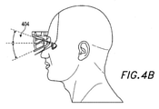
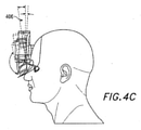
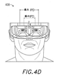
図4A-4Dを参照すると、健康システムは、ユーザ毎にカスタマイズされてもよい。ユーザの頭部形状402が、図4Aに示されるように、頭部搭載患者装着型健康システムをフィッティングするときに考慮されてもよい。同様に、眼コンポーネント404(例えば、光学、光学のための構造等)が、図4Bに示されるように、水平におよび垂直の両方におけるユーザの快適性のために回転または調節されてもよい。1つまたはそれを上回る実施形態では、図4Cに示されるように、ユーザの頭部に対して設定された頭部の回転点は、ユーザの頭部の形状に基づいて調節されてもよい。同様に、瞳孔間距離(IPD)(すなわち、ユーザの眼間の距離)が、図4Dに示されるように、補償されてもよい。
With reference to FIGS. 4A-4D, the health system may be customized for each user. The user's
ユーザにおいて実施される種々の測定および較正に加え、患者装着型健康システムは、患者識別およびセキュア通信のために、ユーザについてのバイオメトリックデータのセットを追跡するように構成されてもよい。例えば、システムは、患者識別のために虹彩認識および/または網膜マッチングを実施し、眼移動、眼移動パターン、瞬目パターン、眼輻輳・開散運動、疲労パラメータ、眼色の変化、焦点距離の変化、および光学拡張現実体験をユーザに提供する際に使用され得る、多くの他のパラメータを追跡してもよい。保険医療用途のために使用されるARデバイスの場合、前述の側面のうちのいくつかは、一般的に利用可能なARデバイスの一部であってもよく、他の特徴は、特定の健康関連用途のために組み込まれてもよいことを理解されたい。 In addition to the various measurements and calibrations performed at the user, the patient-worn health system may be configured to track a set of biometric data about the user for patient identification and secure communication. For example, the system performs iris recognition and / or retinal matching for patient identification, eye movement, eye movement pattern, blink pattern, eye congestion / divergence movement, fatigue parameters, changes in eye color, changes in focal distance. , And many other parameters that can be used in providing the user with an optical augmented reality experience may be tracked. For AR devices used for health insurance applications, some of the aforementioned aspects may be part of commonly available AR devices, while other features are specific health related. Please understand that it may be incorporated for the purpose.
ここで図5を参照すると、例示的患者装着型健康ディスプレイデバイスの種々のコンポーネントが、説明されるであろう。他の実施形態は、システムが使用される用途(例えば、特定の診断ツール)に応じて、付加的またはより少ないコンポーネントを有してもよいことを理解されたい。なお、図5は、患者装着型健康システムまたはARデバイスを通して収集および記憶され得る、種々のコンポーネントおよびバイオメトリックデータのタイプのうちのいくつかの基本概念を提供する。図5は、例証的目的のために、右側にブロック図における頭部搭載型健康システム62の簡略化されたバージョンを示す。
With reference to FIG. 5, various components of an exemplary patient-worn health display device will be described. It should be understood that other embodiments may have additional or fewer components depending on the application in which the system is used (eg, a particular diagnostic tool). Note that FIG. 5 provides some basic concepts of various component and biometric data types that can be collected and stored through a patient-worn health system or AR device. FIG. 5 shows a simplified version of the head-mounted
図5を参照すると、好適なユーザディスプレイデバイス62の一実施形態は、フレーム64(図3A-3D)に対応する、筐体またはフレーム108によってユーザの頭部または眼に搭載され得る、ディスプレイレンズ106を備えるように示される。ディスプレイレンズ106は、ユーザの眼20の正面に筐体108によって位置付けられ、投影された光38を眼20の中に反射させ、ビーム成形を促進する一方、また、ローカル環境からの少なくとも一部の光の伝送を可能にするように構成される、1つまたはそれを上回る半透明ミラーを備えてもよい。図示されるように、2つの広視野マシンビジョンカメラ16が、筐体108に結合され、ユーザの周囲の環境を結像する。いくつかの実施形態では、これらのカメラ16は、二重捕捉可視光/非可視(例えば、赤外線)光カメラである。
Referring to FIG. 5, one embodiment of a suitable
図5を継続して参照すると、光38を眼20の中に投影するように構成される、ディスプレイミラーおよび光学を伴う、一対の走査式レーザ成形波面(すなわち、深度のため)光プロジェクタモジュールが、示される。描写される実施形態はまた、発光ダイオード「LED」等の赤外線光源26とペアリングされる、2つの小型赤外線カメラ24を備え、これは、ユーザの眼20を追跡し、レンダリングおよびユーザ入力をサポート可能であるように構成される。システム62はさらに、センサアセンブリ39を特徴とし、これは、3軸加速度計能力ならびに磁気コンパスおよび3軸ジャイロスコープ能力を含み、好ましくは、200Hz等の比較的に高周波数でデータを提供し得る。描写されるシステムはまた、ASIC(特定用途向け集積回路)、FPGA(フィールドプログラマブルゲートアレイ)、および/またはARMプロセッサ(高度縮小命令セット機械)等のセンサ頭部姿勢プロセッサ32を備え、これは、デジタルおよび/またはアナログ処理を実行し、リアルタイムまたはほぼリアルタイムに、ユーザ頭部姿勢を、センサアセンブリ39からのジャイロスコープ、コンパス、および/または加速度計データから計算するように構成されてもよい。システムはまた、画像頭部姿勢プロセッサ36を含んでもよく、これは、捕捉デバイス16から出力される広視野画像情報を使用して、ユーザの頭部姿勢を判定してもよい。
Continuing with reference to FIG. 5, a pair of scanning laser-formed wavefronts (ie, for depth) optical projector modules with display mirrors and optics configured to project light 38 into the
描写される実施形態はまた、GPS(全地球測位システム)サブシステム37を特徴とし、姿勢および測位分析を補助する。加えて、GPSはさらに、ユーザの環境についての遠隔ベース(例えば、クラウドベース)の情報を提供してもよい。本情報は、診断目的のために使用されてもよい。例えば、ユーザが、周囲空気内に高花粉を有するエリアに位置する場合、本情報は、特定の病気を診断および/または処置するために有用であり得る。または、別の実施例では、特定のエリア内の空気汚染についての情報は、有利には、特定のユーザのための処置オプションを検討する際に使用されてもよい。他のタイプの情報(例えば、花粉数、汚染、人口統計、環境毒素、天候および空気品質状態、生活様式統計、保険医療提供者への近接度等)も同様に、1つまたはそれを上回る用途において使用されてもよい。
The embodiment depicted also features a GPS (Global Positioning System)
描写される実施形態はまた、ユーザに表示されるための仮想コンテンツを提供するように構成されるソフトウェアプログラムを起動するハードウェアを特徴とし得る、レンダリングエンジン34を含んでもよい。レンダリングエンジン34は、レンダリングされた画像データがユーザに投影され得るように(例えば、網膜走査ディスプレイに類似する様式における走査レーザ配列18を使用して)、有線または無線コネクティビティ(例えば、105、94、100、102、104)を介して、センサ頭部姿勢プロセッサ32、画像頭部姿勢プロセッサ36、眼追跡カメラ24、および/または投影サブシステム18に動作可能に結合される。投影された光ビーム38の波面は、投影された光の所望の焦点距離と一致するように修正されてもよい。
The embodiment depicted may also include a rendering engine 34, which may feature hardware that launches a software program configured to provide virtual content for display to the user. The rendering engine 34 has wired or wireless connectivity (eg, 105, 94, etc.) so that the rendered image data can be projected to the user (eg, using a
カメラ24(例えば、小型赤外線カメラ)が、眼を追跡し、レンダリングおよびユーザ入力をサポートするために利用されてもよい(例えば、ユーザが見ている場所、合焦させている深度(眼の輻輳・開散運動が焦点深度/遠近調節を推定するために利用され得る)等)。GPS37、ジャイロスコープ、コンパス、および加速度計39が、大まかなおよび/または高速姿勢推定を提供するために利用されてもよい。カメラ16画像および姿勢が、関連付けられたクラウドコンピューティングリソースからのデータと併せて、ローカル世界をマッピングし、ユーザビューを他者および/または仮想または拡張現実コミュニティならびに/もしくは保険医療プロバイダと共有するために利用されてもよい。1つまたはそれを上回る実施形態では、カメラ16は、包括的保険医療および/または健康増進システムもしくは保険医療監視システムの一部として、ユーザが摂取する食品、薬物、栄養素、および毒素を分析するために使用されてもよい。
A camera 24 (eg, a small infrared camera) may be used to track the eye and support rendering and user input (eg, where the user is looking, depth of focus (eye congestion). -The divergent motion can be used to estimate depth of focus / accommodation) etc.). A
図5を継続して参照すると、ディスプレイデバイス62は、薬品分注モジュール21を含み、薬品をユーザに送達してもよい。薬品分注モジュール21は、1つまたはそれを上回る出口22と、出口22を通して分注された薬品を貯蔵するリザーバであり得る、少なくとも1つの薬品容器23とを含んでもよい。出口22は、1つまたはそれを上回るチャネル22aによって、容器23に接続されてもよく、これは、薬品(例えば、液体または気体)を容器23から出口22に伝達する。いくつかの実施形態では、出口22は、単に、フレーム108内の開口部であってもよい、またはフレーム108に取り付けられる、もしくそれとは一体型である、ノズルであってもよい。いくつかの実施形態では、ノズルは、噴霧器であってもよい。いくつかの実施形態では、チャネル22aは、開口部によってフレーム108および/または管類内に形成される。
With reference to FIG. 5, the
1つまたはそれを上回る実施形態では、ディスプレイデバイスは、発光モジュール27を含み、処置プロトコルに基づいて、装着者の眼の処置等のために、光を装着者に選択的に投与してもよい。発光モジュール27は、光源を備えてもよく、これは、多染性偏光、レーザ、発光ダイオード、蛍光灯、ダイクロイックランプ、フルスペクトル光源等を放出する、光エミッタを含んでもよい。いくつかの実施形態では、1つの発光モジュール27が、両眼のために提供されてもよい。いくつかの他の実施形態では、ディスプレイデバイスは、複数の発光モジュール27を含んでもよく、各眼は、光をその眼に指向するように構成される、少なくとも1つの発光モジュールを有してもよい。
In one or more embodiments, the display device comprises a
図5に特徴とされるディスプレイシステム62内のハードウェアの多くは、直接、ディスプレイ106およびユーザの眼20に隣接する、筐体108に結合されるように描写されるが、描写されるハードウェアコンポーネントは、例えば、図3Dに示されるように、ベルト搭載型コンポーネント等の他のコンポーネント内に搭載または格納されてもよい。加えて、本明細書に記載されるように、複数のセンサおよび他の機能モジュールは、例証および説明を容易にするために、ともに示される。しかしながら、いくつかの実施形態は、これらのセンサおよび/またはモジュールのうちの1つもしくはサブセットのみを含んでもよいことを理解されたい。
Much of the hardware in the
いくつかの実施形態では、図5に特徴とされるシステム62のコンポーネントは全て、画像頭部姿勢プロセッサ36、センサ頭部姿勢プロセッサ32、およびレンダリングエンジン34を除き、直接、ディスプレイ筐体108に結合され、後者の3つおよびシステムの残りのコンポーネント間の通信は、超広帯域等の無線通信または有線通信によって行われてもよい。描写される筐体108は、好ましくは、頭部搭載型かつユーザによって装着可能である。また、これは、ユーザの耳の中に挿入され、音をユーザに提供するために利用され得るもの等、スピーカ(例えば、スピーカ66、図3A-3D)を特徴としてもよい。
In some embodiments, all components of the
ユーザの眼20の中への光38の投影に関して、いくつかの実施形態では、カメラ24が、ユーザの眼20が見ている(例えば、2つの眼の視線が交差する)場所を測定するために利用されてもよく、その情報は、眼20の焦点または遠近調節の状態を判定するために使用されてもよい。眼によって合焦される全ての点の3次元表面は、「単視軌跡」と呼ばれる。焦点距離は、有限数の深度をとってもよい、または無限に変動してもよい。物理的にまたは事実上、輻輳・開散運動距離から投影される光は、対象眼20に合焦されて現れる一方、輻輳・開散運動距離の正面または背面の光は、ぼける。
With respect to the projection of the light 38 into the user's
さらに、理論によって限定されるわけではないが、約0.7ミリメートル未満のビーム直径を伴う空間的にコヒーレントな光は、眼が合焦する場所にかかわらず、ヒトの眼によって正しく分解されることが発見されている。本理解を前提として、適切な焦点深度の錯覚を作成するために、眼の輻輳・開散運動が、カメラ24を用いて追跡されてもよく、レンダリングエンジン34および投影サブシステム18は、単視軌跡上またはそれに近接する全ての仮想オブジェクトを合焦内に、全ての他の仮想オブジェクトを可変程度の合焦外に(すなわち、意図的に作成されたぼけを使用して)レンダリングするために利用されてもよい。好ましくは、システム62は、約60フレーム/秒またはそれを上回るフレームレートでユーザにレンダリングする。上記に説明されるように、好ましくは、カメラ24が、眼追跡のために利用されてもよく、ソフトウェアが、輻輳・開散運動幾何学形状だけではなく、また、ユーザ入力としての役割を果たすための焦点場所キューを選別するように構成されてもよい。好ましくは、そのようなディスプレイシステムは、昼間または夜間使用のために好適な明度およびコントラストを用いて構成される。
Furthermore, spatially coherent light with a beam diameter of less than about 0.7 mm, but not limited by theory, is correctly decomposed by the human eye regardless of where the eye is in focus. Has been discovered. Given this understanding, the congestion and divergence movements of the eye may be tracked using the
いくつかの実施形態では、ディスプレイシステムは、好ましくは、約20ミリ秒未満の視覚的オブジェクト整合、約0.1度未満の角度整合、および約1弧分の分解能の待ち時間を有し、これは、理論によって限定されるわけではないが、ヒトの眼のほぼ限界であると考えられる。ディスプレイシステム62は、位置特定システムと統合されてもよく、これは、GPS要素、光学追跡、コンパス、加速度計、および/または他のデータソースを伴い、位置および姿勢判定を補助してもよい。位置特定情報は、関連世界のユーザのビュー内の正確なレンダリングを促進するために利用されてもよい(例えば、そのような情報は、ディスプレイシステムがそれが実世界に対して位置する場所を把握することを促進するであろう)。
In some embodiments, the display system preferably has a visual object match of less than about 20 ms, an angle match of less than about 0.1 degrees, and a latency of about one arc of resolution. Is considered to be almost the limit of the human eye, though not limited by theory. The
ユーザ装着型健康システム(例えば、眼科システム)のいくつかの実施形態の一般的コンポーネントを説明したので、保険医療および診断に関連する付加的コンポーネントおよび/または特徴が、以下に議論されるであろう。以下に説明される特徴のうちのいくつかは、ユーザ装着型健康システムの種々の実施形態または健康目的のために使用されるARシステムの多くの実施形態に共通であるであろう一方、その他は、健康診断および処置目的のために、付加的またはより少ないコンポーネントを要求するであろうことを理解されたい。 Having described the general components of some embodiments of user-worn health systems (eg, ophthalmic systems), additional components and / or features related to insurance medical care and diagnostics will be discussed below. .. Some of the features described below will be common to various embodiments of user-worn health systems or many embodiments of AR systems used for health purposes, while others It should be understood that additional or less components will be required for health examination and treatment purposes.
いくつかの実施形態では、ユーザ装着型健康システムは、ユーザの眼の遠近調節に基づいて、1つまたはそれを上回る仮想画像を表示するように構成される。ユーザが画像が投影されている場所に合焦するように強制する、以前の3Dディスプレイアプローチと異なり、いくつかの実施形態では、ユーザ装着型健康システムは、投影された仮想コンテンツの焦点を自動的に変動させ、ユーザに提示される1つまたはそれを上回る画像のより快適な視認を可能にするように構成される。例えば、ユーザの眼が、1mの現在の焦点を有する場合、画像は、ユーザの焦点と一致するように投影されてもよい。または、ユーザが、焦点を3mに偏移させる場合、画像は、新しい焦点と一致するように投影される。したがって、ユーザを所定の焦点に強制するのではなく、いくつかの実施形態のユーザ装着型健康システムまたはARディスプレイシステムは、ユーザの眼がより自然な様式で機能することを可能にする。 In some embodiments, the user-worn health system is configured to display one or more virtual images based on the accommodation of the user's eyes. Unlike previous 3D display approaches, which force the user to focus on where the image is projected, in some embodiments the user-worn health system automatically focuses the projected virtual content. It is configured to allow for more comfortable viewing of one or more images presented to the user. For example, if the user's eye has a current focus of 1 m, the image may be projected to match the user's focus. Alternatively, if the user shifts the focus to 3 m, the image is projected to match the new focus. Thus, rather than forcing the user to a predetermined focus, some embodiments of a user-worn health system or AR display system allow the user's eyes to function in a more natural manner.
そのようなユーザ装着型健康システムは、仮想現実デバイスに対して典型的に観察される、眼精疲労、頭痛、および他の生理学的症状の発生を排除または低減させ得る。これを達成するために、患者装着型健康システムの種々の実施形態は、1つまたはそれを上回る可変焦点要素(VFE)を通して、仮想画像を可変焦点距離に投影するように構成される。1つまたはそれを上回る実施形態では、3D知覚は、画像をユーザから離れた固定焦点面に投影する、多平面焦点システムを通して達成されてもよい。他の実施形態は、可変平面焦点を採用し、焦点面は、ユーザの焦点の現在の状態と一致するように、z-方向に往復して移動される。 Such a user-worn health system can eliminate or reduce the occurrence of eye strain, headache, and other physiological symptoms typically observed for virtual reality devices. To achieve this, various embodiments of the patient-worn health system are configured to project a virtual image to a variable focal length through one or more variable focal length elements (VFE). In one or more embodiments, 3D perception may be achieved through a multi-plane focus system that projects the image onto a fixed focus plane away from the user. Another embodiment employs variable planar foci, where the focal plane is reciprocated in the z- direction to match the current state of the user's focal point.
多平面焦点システムおよび可変平面焦点システムの両方において、患者装着型健康システムは、眼追跡を採用し、ユーザの眼の輻輳・開散運動を判定し、ユーザの現在の焦点を判定し、仮想画像を判定された焦点に投影してもよい。 In both multi- and variable-plane focus systems, patient-worn health systems employ eye tracking to determine the user's eye congestion / divergence movement, determine the user's current focus, and virtual images. May be projected onto the determined focal point.
任意の波長の光が、ユーザの眼の中に投影されてもよい。可視光に加え、赤外線光または光の他の波長も同様に、患者装着型健康システムを通して投影されてもよい。患者装着型健康システムの本側面は、以下に説明されるであろうように、健康異常に関して、結像、診断、処置、および/または補償のために使用されてもよい。 Light of any wavelength may be projected into the user's eyes. In addition to visible light, infrared light or other wavelengths of light may be similarly projected through a patient-worn health system. This aspect of a patient-worn health system may be used for imaging, diagnosis, treatment, and / or compensation for health abnormalities, as described below.
保険医療および診断の状況下では、ユーザに提示される1つまたはそれを上回る画像のタイプ、周波数、配色、場所等が、有利には、1つまたはそれを上回る障害の診断、患者監視、および/または処置のために操作されてもよい。例えば、ある病気は、他方の眼に関連して、一方の眼の補強を要求し得る。この目的を達成するために、処置プロトコルは、例えば、強い方の眼と比較して増加された刺激を弱い方の眼に提供することによって、弱い方の眼を「訓練」するために考案されてもよい。または、別の実施例では、網膜の特定の部分は、黄斑変性に起因して、減少された感度を有し得る。これに対抗するために、画像は、変調または再フォーマットされ、網膜の周縁に投影され、それによって、ユーザの減少された視野を補償してもよい。したがって、以下にさらに詳細に説明されるであろうように、仮想画像投影に関連するいくつかのパラメータを変調させる健康システムの能力は、ある健康異常を診断、監視、および/または処置するために使用されてもよい。 Under insurance medical and diagnostic situations, one or more image types, frequencies, color schemes, locations, etc. presented to the user are advantageous in diagnosing one or more disorders, patient monitoring, and / Or may be manipulated for treatment. For example, one disease may require reinforcement of one eye in relation to the other eye. To this end, treatment protocols have been devised to "train" the weaker eye, for example, by providing increased stimulation to the weaker eye compared to the stronger eye. You may. Alternatively, in another embodiment, certain parts of the retina may have reduced sensitivity due to macular degeneration. To counter this, the image may be modulated or reformatted and projected onto the periphery of the retina, thereby compensating for the user's reduced field of view. Therefore, as will be described in more detail below, the ability of health systems to modulate some parameters associated with virtual image projection is to diagnose, monitor, and / or treat certain health abnormalities. May be used.
加えて、上記に概略された種々の原理を使用して、健康システムは、刺激-応答測定分析プロセスを使用して、診断を提供するように設計されてもよい。これら等のデバイスは、臨床医によって使用され得るか、または他の実施形態では、ある病気が、単に、査定される、もしくは症状を患者によって認めさせ得るか(例えば、眼精疲労、ドライアイ、高血圧症、脳卒中または発作の発症等)のいずれかである。これは、ユーザが、その健康を能動的に制御し、ある症状の発症時、それらに先を見越して対処することによって、疾患の発症を防止することに大きく役立ち得る。そのような診断および/または査定は、例えば、現時点のデータを1つまたはそれを上回る追跡されたバイオメトリックパラメータおよび環境変化に関連する履歴データとともに分析することによって行われてもよい。1つまたはそれを上回る実施形態では、健康システムはまた、情報キューを提供する、アラートをユーザおよび/または医師もしくは他者に送信する、もしくは他の応答手段を補助するように構成されてもよい。 In addition, using the various principles outlined above, the health system may be designed to provide diagnostics using a stimulus-response measurement analysis process. Devices such as these can be used by a clinician, or in other embodiments, a disease can simply be assessed or manifested by the patient (eg, eye strain, dry eye, etc.). Hypertension, stroke or onset of seizures, etc.). This can be of great help to prevent the onset of disease by the user by actively controlling their health and proactively coping with certain symptoms when they occur. Such diagnosis and / or assessment may be performed, for example, by analyzing current data with one or more tracked biometric parameters and historical data associated with environmental changes. In one or more embodiments, the health system may also be configured to provide information queues, send alerts to users and / or doctors or others, or assist other means of response. ..
健康システムは、例えば、ユーザを診断、監視、または処置するための健康システムのソフトウェア制御実装におけるように、自律的(すなわち、臨床医または他の人物からの入力または制御を伴わずに、結果を直接ユーザまたは他の人物もしくはエンティティに提供する)である、または半自律的(すなわち、臨床医または他の人物からのある程度の入力もしくは制御)であるように構成されてもよいことを理解されたい。他の実施形態では、健康システムは、臨床医または他の人物によって完全制御されてもよい(例えば、クラウドベースの実装等のネットワーク化またはあらゆる遠隔ベースにおいて、もしくは健康システムが患者を検査するために臨床医によって装着される実装において)。 The health system produces results autonomously (ie, without input or control from a clinician or other person, as in a software controlled implementation of the health system for diagnosing, monitoring, or treating a user, for example. It should be understood that it may be configured to be (provided directly to the user or other person or entity) or semi-autonomous (ie, some input or control from the clinician or other person). .. In other embodiments, the health system may be fully controlled by a clinician or other person (eg, networked such as a cloud-based implementation or at any remote base, or for the health system to examine a patient. In the implementation worn by the clinician).
いくつかの実施形態では、健康システムは、いくつかの付加的健康関連センサとともに設計されてもよい。これらは、例えば、加速度計、ジャイロスコープ、温度センサ、圧力センサ、光センサ、非侵襲性血糖値センサ、ETCO2、EEG、および/または他の生理学的センサ等を含み、ユーザの1つまたはそれを上回る生理学的応答を監視してもよい。 In some embodiments, the health system may be designed with some additional health-related sensors. These include, for example, accelerometers, gyroscopes, temperature sensors, pressure sensors, optical sensors, non-invasive blood glucose sensors, ETCO2, EEG, and / or other physiological sensors, etc. Exceeding physiological responses may be monitored.
本明細書に説明されるように、健康システムは、1つまたはそれを上回る実施形態では、眼追跡モジュールを備える。眼追跡モジュールは、1つまたはそれを上回る仮想画像の投影のために、(輻輳・開散運動と遠近調節との間の直接関係を通した)適切な正常遠近調節を判定するために、ユーザの眼の輻輳・開散運動を判定するように構成されてもよく、また、1つまたはそれを上回る眼関連パラメータ(例えば、眼の位置、眼移動、眼パターン等)を追跡するように構成されてもよい。本データは、以下に説明されるであろうように、いくつかの健康関連診断および処置用途のために使用されてもよい。 As described herein, the health system comprises, in one or more embodiments, an eye tracking module. The eye tracking module determines the proper normal accommodation (through the direct relationship between accommodation / divergence movement and accommodation) for the projection of one or more virtual images. It may be configured to determine eye congestion / divergence movements, or to track one or more eye-related parameters (eg, eye position, eye movement, eye pattern, etc.). May be done. This data may be used for several health-related diagnostic and therapeutic applications, as described below.
本明細書の説明から明白であろうように、健康システムは、診断、監視、および療法のために使用されてもよく、これは、眼関連診断、監視、および療法を含むことができる。眼関連用途では、健康システムは、眼科システムと称され得る。また、本明細書の説明から明白であるように、デバイスのユーザ(または装着者)は、患者と称され得、診断、監視、および療法は、デバイスによって、そのユーザにおいて行われる。いくつかの他の実施形態では、ユーザは、臨床医であってもよく、患者は、ユーザによって評価および処置され得る、第三者であってもよい。また、診断および監視は、概して、健康分析と称され得ることを理解されたい。
ライトフィールドプロセッサシステム
As will be apparent from the description herein, the health system may be used for diagnosis, monitoring, and therapy, which may include eye-related diagnosis, monitoring, and therapy. In eye-related applications, the health system may be referred to as an ophthalmic system. Also, as will be apparent from the description herein, the user (or wearer) of the device may be referred to as a patient, and diagnosis, monitoring, and therapy are performed by the device in that user. In some other embodiments, the user may be a clinician and the patient may be a third party who can be evaluated and treated by the user. It should also be understood that diagnosis and monitoring can generally be referred to as health analysis.
Lightfield processor system
図6は、ユーザの視野の少なくとも一部からライトフィールド画像データ(例えば、写真および/またはビデオ)を捕捉し、次いで、捕捉されたライトフィールド画像データを処理し、処理されたライトフィールド画像データをユーザに表示するためのライトフィールドプロセッサシステム600を図示する。ライトフィールドプロセッサシステム600は、1つまたはそれを上回る外向きに面した一体型結像カメラ16と、ライトフィールドプロセッサ70と、1つまたはそれを上回る一体型結像ディスプレイ62とを含むことができる。これらのコンポーネントはそれぞれ、本明細書で議論されるウェアラブル仮想/拡張現実および健康システムの一部として提供されることができる。いくつかの実施形態では、ライトフィールド画像データは、ユーザが表示されるライトフィールド画像データ内に遅れまたは遅延を知覚しないように、実質的にリアルタイムで捕捉、処理、および表示される。
FIG. 6 captures light field image data (eg, a photo and / or video) from at least a portion of the user's field of view, then processes the captured light field image data, and the processed light field image data. The light
すぐ上で述べられたように、ライトフィールドプロセッサシステム600の一側面は、従来の2次元写真および/またはビデオではなく、ライトフィールド画像データを捕捉、処理、および表示することである。空間世界は、3次元であるが、従来の写真およびビデオは、2次元画像のみを記録する。したがって、従来のカメラは、光と3次元世界内の事物の複雑な相互作用を、カメラの視野内のオブジェクト空間から検出された光強度の平坦な2次元マップに低減させる。本平坦化効果は、カメラの視野内のオブジェクト平面上の異なる点において放出、反射、および/または散乱された光線が、レンズによって画像平面上の対応する点に合焦される、結像の結果である。角度情報は、本プロセスでは、喪失される。すなわち、従来の画像における所与のピクセルにおいて記録される光強度は、視野内のオブジェクト平面上の対応する点から異なる角度配向を伴って生じる、光線の個別の強度寄与を示さない。代わりに、従来の写真およびビデオでは、画像平面内の各点において測定された強度は、視野内のオブジェクト平面上の対応する点から異なる角度配向を伴ってカメラに入射する、種々の光線の組み合わせられた強度を示す。従来のカメラにおける3次元から2次元への平坦化は、画像の情報コンテンツを有意に限定する。
As just mentioned above, one aspect of the
対照的に、ライトフィールドデータは、視野内の種々の点から生じる光の方向および強度についての情報を含む。したがって、従来のカメラを用いて取得される典型的写真は、2次元画像放射照度マップであるが、ライトフィールドデータは、視野内の複数の(x、y)点のそれぞれから複数の角度(θx、θy)において発出する光線の強度または放射照度についての情報を含み得るため、4次元と見なされ得る。ライトフィールドディスプレイを用いて再現されると、ライトフィールド画像は、実際の物理的場面を直接視認する場合に類似する、3次元表現を視認者に提供する。 In contrast, light field data contains information about the direction and intensity of light originating from various points in the field of view. Therefore, a typical photograph acquired using a conventional camera is a two-dimensional image irradiance map, but the light field data is a plurality of angles (θx) from each of a plurality of (x, y) points in the field of view. , Θ y ) can contain information about the intensity or irradiance of the light beam emitted, so it can be considered four-dimensional. When reproduced using a light field display, the light field image provides the viewer with a three-dimensional representation similar to when directly viewing an actual physical scene.
外向きに面した一体型結像カメラ16は、ライトフィールドデータを捕捉可能な任意のカメラまたはデバイスであることができる。1つのそのようなデバイスの実施例は、図7に関して本明細書に説明される。いくつかの実施形態では、1つまたはそれを上回る外向きに面した一体型結像カメラ16は、図3-5に示されるように、ウェアラブルシステムと統合されることができる。2つの(またはそれを上回る)外向きに面した一体型結像カメラ16が、提供されることができ、それぞれ、概して、数値的ライトフィールド画像データを捕捉するために使用され、これは、ユーザの眼のうちの1つに表示されるであろう。具体的には、左外向きに面した一体型結像カメラ16は、ユーザの左眼の正常視野と重複する視野を有するように提供および整合されることができる。同様に、右外向きに面した一体型結像カメラ16は、ユーザの右眼の正常視野と重複する視野を有するように提供および整合されることができる。
The outward facing integrated
ライトフィールドプロセッサ70は、例えば、本明細書に説明されるローカル処理およびデータモジュール70を使用して実装されることができる。ライトフィールドプロセッサ70は、捕捉された4次元の数値的ライトフィールド画像データを一体型結像カメラ16および/または非一過性コンピュータメモリから受信する。ライトフィールドプロセッサは、種々の動作を捕捉されたライトフィールド画像データ上にコンピュータ的に実施することができる。そのような動作は、正または負の球面および/または円柱屈折力を数値的ライトフィールド画像データにコンピュータ的に追加し、数値的ライトフィールド画像データによって表される1つまたはそれを上回る波面を識別し、そのような波面の曲率をコンピュータ的に改変し、ライトフィールド画像データを選択された深度平面に合焦させ、プリズム屈折力をライトフィールド画像データに追加し、仮想オブジェクトまたは他のVR/ARコンテンツを画像データに追加し、オブジェクトまたは他のコンテンツを画像データから削除し、ライトフィールド画像データを上、下、左、または右に偏移させ、捕捉されたライトフィールド画像データの選択された下位部分を拡大し、画像データの空間および/または波長フィルタリングを実施すること等を含むことができる。
The
いくつかの実施形態では、ライトフィールドプロセッサ70は、眼科処方箋またはユーザの眼の他の特性に基づいて、捕捉された数値的ライトフィールド画像データを処理する。(眼科処方箋または他の眼特性は、ライトフィールドプロセッサ70にユーザまたは別のデバイス(例えば、非一過性コンピュータメモリ)から入力されることができる、もしくは眼科処方箋または他の眼特性は、本明細書にさらに説明されるように、ライトフィールドプロセッサシステム600自体によって測定されることができる。)例えば、捕捉された数値的ライトフィールド画像データは、ユーザの視力の少なくとも1つの側面を改善するように処理されることができる。いくつかの実施形態では、数値的ライトフィールド画像データは、少なくとも部分的に、ユーザの近視、遠視、乱視、老眼、斜視、弱視、黄斑変性、高次屈折誤差、色収差、または微小障害を補正するように、処理されることができる。他のタイプの補正もまた、可能性として考えられる。
In some embodiments, the
一体型結像ディスプレイ62は、ライトフィールド画像データを表示可能な任意のデバイスであることができる。1つのそのようなデバイスの実施例は、図7に関して本明細書に説明される。いくつかの実施形態では、1つまたはそれを上回る一体型結像ディスプレイ62は、図3-5に示されるように、ウェアラブルシステムと統合されることができる。一体型結像ディスプレイ62は、ユーザがその実世界環境を視認することを可能にするように、部分的に透明であることができる。代替として、一体型結像ディスプレイは、代わりに、外向きに面した一体型結像カメラ16に完全に依拠し、ユーザにその実世界環境からの画像データを提供してもよい。2つの一体型結像ディスプレイ62が、提供されることができ、それぞれ、概して、処理されたライトフィールド画像データをユーザの眼のうちの1つに表示するために使用される。具体的には、左の一体型結像ディスプレイ62は、ライトフィールド画像データをユーザの左眼に表示するために提供および整合されることができる。同様に、右の一体型結像ディスプレイ62は、ライトフィールド画像データをユーザの右眼に表示するために提供および整合されることができる。
The
図7は、図6のライトフィールドプロセッサシステム600の実施形態の略図である。外向きに面した一体型結像カメラ16は、マイクロレンズ702の2次元アレイと、感光ピクセルを伴う光検出器704の対応する2次元アレイとを含むことができる。光検出器アレイ704は、例えば、相補的金属酸化物半導体(CMOS)センサ、電荷結合素子(CCD)センサ、CMOSまたはCCDセンサのアレイ、もしくは光エネルギーを検出およびデジタル化可能な任意の他のデバイスであることができる。光検出器のアレイは、平面表面または湾曲表面を形成することができる(例えば、光検出器のアレイは、眼の周囲の半径方向に湾曲され、眼が見ている可能性のある任意の場所からの光の捕捉を促進することができる)。マイクロレンズアレイ702は、光をユーザの視野内のオブジェクト空間内の点706から集める。各マイクロレンズ、すなわち、レンズレットは、視野から一体型結像カメラ16に入射する光の波面の空間的に局所化された領域をサンプリングし、局所角度情報が光検出器アレイ704上に記録されることを可能にする。このように、光検出器アレイ704は、異なる角度方向から器具に到着する、光線の個別の強度を検出することができる。例えば、図7に示されるように、光708の種々の円錐が、オブジェクト空間内の異なる角度(θx、θy)において点706から生じる。各レンズレット702は、異なる角度配向を伴って点706から生じる光708の円錐を光検出器アレイ704上に合焦させる。単一点706のみが、図示されるが、各レンズレット702は、オブジェクト空間内の(x、y)平面上の点毎に、本機能を実施する。言い換えると、各レンズレット702は、アレイ内の他のレンズレット702によって作成された基本画像と若干異なる視点を伴う、オブジェクト空間内の場面の基本画像を作成する。各基本画像は、光検出器アレイ704内の光検出器のグループによって記録される。集合的に、基本画像の本2次元アレイは、一体画像と称されるものを形成する。一体画像は、場面の種々の可能性として考えられるライトフィールド表現のうちの1つである。これは、基本画像の2次元アレイを含み、それぞれ、若干異なる視点から捕捉される。
FIG. 7 is a schematic diagram of an embodiment of the light
一体型結像カメラ16から捕捉されたライトフィールド画像データは、一体型結像カメラによってデジタル化された後、種々の数値的形態で表されることができる。これは、ライトフィールドプロセッサ70が、数学的操作(上記に説明されるもの等)を捕捉されたライトフィールド画像データに実施することを可能にする。いったんライトフィールドプロセッサ70が、所望の数学的操作を捕捉されたライトフィールド画像データに実施すると、処理されたライトフィールド画像データは、次いで、一体型結像ディスプレイ62に通過される。いくつかの実施形態では、処理されたライトフィールド画像データは、それぞれ、処理された基本画像のセットから成る、1つまたはそれを上回る処理された一体画像の形態において、一体型結像ディスプレイ62に通過されることができる。
The light field image data captured from the
図7に示されるように、一体型結像ディスプレイ62は、マイクロレンズ712の2次元アレイと、光源714の2次元アレイとを含む。一体型結像ディスプレイ62は、コントローラを含み、例えば、処理されたライトフィールド画像データを使用して、光源714のアレイを変調させてもよい。光源714のアレイは、例えば、発光ダイオード(LED)の赤色、緑色、青色(RGB)アレイであることができる。いくつかの実施形態はまた、赤外線放出光源を含み、本明細書の以降で議論される理由のいずれかのために、赤外線光を装着者の眼の中に投影してもよい。代替として、光源714のアレイは、液晶ディスプレイ(LCD)パネルまたはある他のタイプのディスプレイパネルとして実装されることができる。各光源は処理された一体画像のピクセルまたはサブピクセルに対応する光を放出するために使用されることができる。各光源714から放出された光は、次いで、レンズレット712のうちの1つによって、ユーザの眼の前の空間内の対応する点716に投影される。いくつかの実施形態では、各レンズレット712は、処理された基本画像のうちの1つを投影する。投影された基本画像のそれぞれからの光の重複は、物理的ライトフィールドを再作成し、これは、ユーザによって視認されることができる。本物理的ライトフィールドは、ユーザによって、実際の3次元場面を視認している場合に類似する3次元として知覚される。ライトフィールドプロセッサ70が、一体型結像カメラ16によって収集された一体画像を改変すべきではない場合、一体型結像ディスプレイ62によって作成された物理的ライトフィールドは、カメラ16の視野内のオブジェクト空間内に存在する、同一物理的ライトフィールドの表現となるであろう。これは、図7に示され、光718の全ての投影された円錐の交差点は、放射照度分布をもたし、これは、オリジナル3次元場面の放射輝度を再現する。別様に、ライトフィールドプロセッサ70が、一体画像を改変するために使用される場合、一体型結像ディスプレイ62によって投影された物理的ライトフィールドは、カメラ16の視野内のオブジェクト空間内に存在する、物理的ライトフィールドの同様に改変されるバージョンとなる。
As shown in FIG. 7, the
図7は、ライトフィールド捕捉/処理/表示システム600の一実施形態を図示するが、他の実施形態もまた、可能性として考えられる。例えば、図7に示される一体型結像カメラ16は、ライトフィールド画像データを捕捉可能な任意のタイプのデバイスと置換され得る。同様に、図7に示される一体型結像ディスプレイ62もまた、ライトフィールド画像データを表示可能な任意のタイプのデバイスと置換され得る。
近視、遠視、乱視、および高次収差の補正
FIG. 7 illustrates one embodiment of the light field capture / processing /
Correction of myopia, hyperopia, astigmatism, and higher order aberrations
図8は、図6および7に示されるライトフィールドプロセッサシステム600を使用して、ユーザのために、近視、遠視、および/または乱視を補正するための方法800を図示する、フローチャートである。方法800は、ブロック810から開始し、システム600のライトフィールドプロセッサ70が、ユーザの屈折力測定を受信する。屈折力測定は、球面屈折力、円柱屈折力、および/または円柱屈折力軸測定を含む、眼鏡に関するユーザの光学処方箋を備えてもよい。これらの測定は、システム600自体によって実施されてもよい(本明細書でさらに議論されるように)、またはユーザもしくは別個の診断デバイスから受信されてもよい。光学処方箋は、ライトフィールドプロセッサシステム600の初期化の間、システム600の較正の間、眼処方箋コンフィギュレータプログラムの一部として(例えば、眼位計または他の視力検査を使用して)、またはライトフィールドプロセッサシステムの使用の間の任意の時間において、判定されてもよい。バイオメトリックデータは、ユーザおよび関連付けられた光学処方箋を識別するために使用されてもよい。
FIG. 8 is a flow
すぐ上で述べられたように、ユーザの眼の屈折力測定がライトフィールドプロセッサシステム600に入力され得る、多くの方法が存在する。いくつかの実施形態では、ユーザは、単に、ライトフィールドプロセッサシステム600に情報を提供してもよい。例えば、ユーザは、処方箋をユーザインターフェースに入力してもよい。または、他の実施形態では、ライトフィールドプロセッサシステム600は、自動的または双方向的に、ユーザの光学処方箋を判定するように構成されてもよい。例えば、ライトフィールドプロセッサシステムは、眼処方箋コンフィギュレータプログラムを経由して、手動でかつ双方向的に、ユーザの処方箋を判定してもよい。ライトフィールドプロセッサ70は、収集されたライトフィールド画像データの焦点または改変された波面を調節する際、離散粒度ステップを伴って事前にプログラムされてもよい。焦点の調節または波面の改変は、球面屈折力の調節および/または円柱屈折力/軸の調節を含んでもよい。ユーザは、適切なフィードバック機構(例えば、ユーザインターフェース)を通して、ライトフィールドプロセッサシステムへの屈折力改変の所望の量を規定してもよい。または、いくつかの実施形態では、ユーザは、ユーザが快適な視認処方箋に到着するまで、処方箋値を漸次的に増加または減少させるオプションを有してもよい。
As just mentioned above, there are many ways in which a user's eye refractive power measurement can be input to the
いくつかの実施形態では、ライトフィールドプロセッサシステム600は、眼追跡システム、自動屈折、収差測定、または本明細書に説明されるような他のシステムを介して、眼を監視および追跡することに基づいて、ユーザ入力を要求せずに、眼毎に、ユーザの光学処方箋を自動的に測定してもよい(かつ眼毎に、リアルタイムで適用される補正を漸次的に変化させる)。いくつかの実施形態では、ライトフィールドプロセッサシステム600は、生体フィードバックシステム(本明細書で議論される)を利用して、適用される補正処方箋を自動的に変化させてもよい。
In some embodiments, the light
いくつかの実施形態では、ライトフィールドプロセッサシステム600は、ユーザの光学処方箋を第三者システムから受信するように構成されてもよい。例えば、医師は、ユーザ光学処方箋を無線で(例えば、インターネット、Bluetooth(登録商標)接続等を経由して)送信可能であってもよく、これは、受信機によって受信され、ライトフィールドプロセッサ70のデジタルメモリ内に記憶される。
In some embodiments, the
ブロック820では、システム600の外向きに面した一体型結像カメラ16が、ライトフィールド画像データを捕捉し、捕捉されたライトフィールド画像データをライトフィールドプロセッサ70に入力する。本明細書に議論されるように、捕捉されたライトフィールドは、一体型結像ディスプレイ62によって表示されることに先立って、数学的に操作されることができる。様々な数学的操作が、実施されることができるが、数学的操作のうちのいくつかは、その光学処方箋、角膜の形状または曲率、眼の長さ等のユーザの眼の1つまたはそれを上回る特性に基づいて、少なくとも部分的に、捕捉されたライトフィールド画像データを補正するために使用されてもよい。ライトフィールドプロセッサ70は、次いで、改変されたライトフィールドをユーザに表示する前に、リアルタイム変更をユーザの入射ライトフィールドに行うために使用されることができる。
At
いくつかの実施形態では、ライトフィールドプロセッサによって適用される、具体的補正は、ユーザの視力が経時的に変化するにつれて、視力障害を動的に補正するように調節されることができる。例えば、いくつかの実施形態では、ライトフィールドプロセッサシステム600は、眼処方箋コンフィギュレータプログラムを始動させることによって、動的視力補正を実装してもよい。ライトフィールドプロセッサシステムは、ユーザアクティブ化の有無にかかわらず、ある時間のインターバルにおいて、ユーザの処方箋を判定するように構成されることができる。したがって、ライトフィールドプロセッサシステムは、第1の光学処方箋を第1の時間に動的に識別してもよく、その処方箋に基づいて、視力補正を調節してもよく、第2の光学処方箋を第2の時間において識別してもよく、その第2の処方箋に基づいて、視力補正を調節してもよい。
In some embodiments, the specific corrections applied by the light field processor can be adjusted to dynamically correct the visual impairment as the user's visual acuity changes over time. For example, in some embodiments, the
少なくとも部分的に、ライトフィールドプロセッサ70によって補正され得る、一般的視力障害は、近眼(すなわち、近視)、遠眼(すなわち、遠視)、および乱視を含む。従来、これらの障害は、球面および/または円柱レンズを使用して補正されている。しかしながら、ライトフィールドプロセッサシステム600は、代替として、捕捉されたライトフィールドのコンピュータ的操作を介して、これらの障害を補正することができる。
Common visual impairments that can be corrected, at least in part, by the
近視の場合、ユーザの視野内の1つまたはそれを上回るオブジェクトと関連付けられた光は、図9Aに示されるように、網膜上ではなく、網膜の正面に合焦される。これは、オブジェクトを焦点外から現れさせる。ここで図9Bを参照すると、従来、負の屈折力凹面レンズが障害を補償し、負の屈折力を導入するために使用されることができ、これは、光を網膜上で合焦させる。ライトフィールドプロセッサ70は、図9Bに示される補正凹面レンズと、図6および7に示される外向きに面した一体型結像カメラ16によって捕捉された数値的ライトフィールド画像データの数学的操作を置換することができる。例えば、図8のブロック840に示されるように、ユーザの光学処方箋が、近視を有することを示す場合、ライトフィールドプロセッサ70は、少なくとも部分的に、ユーザの近視を補正するように、ある量の負の球面屈折力波面曲率を選択し、捕捉されたライトフィールド画像データにコンピュータ的に導入する。
In the case of myopia, the light associated with one or more objects in the user's field of view is focused on the front of the retina rather than on the retina, as shown in FIG. 9A. This makes the object appear out of focus. Referring here to FIG. 9B, a negative power concave lens can conventionally be used to compensate for an obstacle and introduce a negative power, which focuses the light on the retina. The
遠視の場合、1つまたはそれを上回るオブジェクトと関連付けられた光は、図10Aに示されるように、網膜上ではなく、網膜の背後に合焦される。これは、オブジェクトを焦点外に現れさせる。ここで図10Bを参照すると、従来、正の屈折力凸面レンズが、障害を補償するために使用されることができる。ここでも、ライトフィールドプロセッサ70は、図10Bに示される補正凸面レンズと、図6および7に示される外向きに面した一体型結像カメラ16によって捕捉されたライトフィールドの数学的操作を置換することができる。例えば、図8のブロック830に示されるように、ユーザの光学処方箋が、遠視を有することを示す場合、ライトフィールドプロセッサ70は、少なくとも部分的に、ユーザの遠視を補正するように、ある量の正の球面屈折力波面曲率を選択し、捕捉されたライトフィールド画像データにコンピュータ的に導入する。
In the case of hyperopia, the light associated with one or more objects is focused behind the retina rather than on the retina, as shown in FIG. 10A. This makes the object appear out of focus. Here, referring to FIG. 10B, conventionally, a positive refractive power convex lens can be used to compensate for the obstacle. Again, the
乱視は、眼が円柱屈折力を呈する(すなわち、眼の屈折力が、1つの子午線に対して測定されるとき、直交子午線に対するものと異なる)、病状である。図11Aに図式的に図示されるように、これは、不規則に成形される角膜によって生じ得る。例えば、1つの子午線に沿った曲率は、垂直子午線に沿った曲率と異なり得る。ここで図11Bを参照すると、従来、乱視は、適切に配向された円柱レンズの導入によって補正されることができる。ここでも、ライトフィールドプロセッサシステム600は、図11Bに示される補正レンズと、図6および7に示される外向きに面した一体型結像カメラ16によって捕捉されたライトフィールドの数学的操作を置換することができる。具体的には、図8のブロック850に示されるように、ライトフィールドプロセッサ70は、ユーザの乱視のために、少なくとも部分的に、捕捉されたライトフィールド画像データを補正するように、ある量の円柱屈折力(ユーザの処方箋によって示される角度軸に配向される)を選択およびコンピュータ的に導入することができる。
Astigmatism is a medical condition in which the eye exhibits cylindrical power (ie, when the power of the eye is measured for one meridian, it is different from that for orthogonal meridians). As illustrated graphically in FIG. 11A, this can be caused by an irregularly shaped cornea. For example, the curvature along one meridian can differ from the curvature along the vertical meridian. Here, referring to FIG. 11B, conventionally, astigmatism can be corrected by introducing a properly oriented cylindrical lens. Again, the light
しかしながら、ライトフィールドプロセッサシステム600は、焦点ぼけおよび/または乱視等の単純低次光学収差の補正に限定されない。実際、ライトフィールドプロセッサ70はまた、同様に、複雑な高次光学収差のために、コンピュータ的補正を捕捉されたライトフィールドに適用することができる。ある場合には、これらの高次収差は、全ての屈折誤差の約10%を考慮してもよい。これらの高次屈折誤差は、眼内に不規則に成形される光学表面によって生じ得、特に、屈折外科手術後に一般的である。例えば、眼の角膜および/または水晶体内の形状不規則性は、高次屈折誤差を眼を通して網膜に通過する光に導入し得る。そのような高次収差は、適切な屈折補正を用いて低減され得る。
However, the light
本明細書に説明されるライトフィールドプロセッサシステム600の種々の実装は、これらの高次収差のために、コンピュータ的補正を入射波面に提供するために適用可能であり得る。そのようなコンピュータ的補正は、ユーザの眼の高次収差の測定に基づいて、ライトフィールドプロセッサ70によって適用されることができる。ゼルニケモード(例えば、乱視、コマ、トレフォイル、球面収差、クワトロフォイル等)によって説明される全ての収差の補正を含む、波面補正は、本明細書に説明されるライトフィールドプロセッサシステム600を利用して行われてもよい。
Various implementations of the
いくつかの実施形態では、ライトフィールドプロセッサシステム600は、本明細書に説明されるように、ユーザの眼の高次収差を測定する能力を有してもよい。これらの測定は、次いで、ライトフィールドプロセッサ70によって、一体型結像カメラ16によって収集されたライトフィールド画像データをコンピュータ的に改変するために使用されることができる。他の実施形態では、ライトフィールドプロセッサ70は、ユーザの眼の高次収差測定を外部デバイスから受信する。例えば、ライトフィールドプロセッサシステム600は、1つまたはそれを上回る送信機および受信機を含み、システムと遠隔処理モジュール72および/または遠隔データリポジトリ74との間のデータの伝送および受信を可能にしてもよい。送信機および受信機は、送受信機の中に組み合わせられてもよい。いくつかの実施形態では、遠隔処理モジュール72および/または遠隔データリポジトリ74は第三者(例えば、医師または他の医療管理者)が、例えば、光学処方箋等のデータを眼科デバイスに伝送することを可能にする、第三者サーバおよびデータベースの一部であってもよい。
In some embodiments, the light
いくつかの実施形態では、高次収差を補正するための方法は、近視、遠視、または乱視を補正するために、図8に説明される方法800に類似してもよい。ライトフィールドプロセッサ70は、最初に、ユーザの眼の高次収差の測定を受信する。これらの測定は、ゼルニケ係数として、角膜のトポグラフィのマップとして、または任意の他の好適なフォーマットにおいて提供されることができる。ライトフィールドプロセッサ70は、次いで、一体型結像カメラ16によって収集されるライトフィールド画像データを受信する。最後に、ライトフィールドプロセッサ70は、少なくとも部分的に、1つまたはそれを上回る高次収差を低減させるように、捕捉されたライトフィールドデータの波面に行うための1つまたはそれを上回る調節を選択する。これらの補正は、コンピュータ的に適用される。
In some embodiments, the method for correcting higher order aberrations may be similar to
ユーザの眼は、高次屈折誤差を被り得、これは、遠近調節の変化に伴って変動する。故に、いくつかの実施形態では、ライトフィールドプロセッサ70は、ユーザの眼の現在の遠近調節に基づいて、および/またはライトフィールド画像データの焦点面に基づいて、入射ライトフィールドに行うための異なる波面調節のセットを選択してもよい。
The user's eye can suffer higher-order refraction errors, which fluctuate with changes in accommodation. Therefore, in some embodiments, the
いくつかの実装では、ライトフィールドプロセッサシステム600はまた、角膜、水晶体、および/または眼の他の解剖学的構造における微視的障害の効果を低減させるように、収集されたライトフィールド画像データを改変するように構成されてもよい。これらの障害は、視覚的品質を損なわせる、複雑な屈折、反射、および散乱パターンを生成し得る。ライトフィールドプロセッサ70は、これらの障害と相互作用するであろう、光線を空間的にフィルタリングし、したがって、視覚的品質を損なわせることに寄与する、それらの光学経路を遮断することができる。これは、ユーザの眼内の障害と相互作用するであろう、収集されたライトフィールド画像データ内の光線を識別し、次いで、それらの選択された光線を処理されたライトフィールドからコンピュータ的に除去することによって行われることができる。
In some implementations, the
いったんライトフィールドプロセッサ70が、所望のコンピュータ的補正を捕捉されたライトフィールド画像データに実施すると、ブロック860では、一体型結像ディスプレイ62は、補正されたライトフィールド画像データをユーザに表示する。
Once the
いくつかの実施形態では、ライトフィールドプロセッサシステム600は、オブジェクトまたは画像を視認する際のユーザの快適性レベルを判定するように構成される、生体フィードバックシステムを備えてもよい。例えば、ユーザの眼が、偏移する、遠近調節を変化させる、瞳孔サイズを変化させる、輻輳・開散運動を変化させる等の場合、これらは、ユーザがオブジェクトまたは画像を快適に視認不能であることのインジケータであり得る。遠近調節または遠近調節と関連付けられた挙動における不安定性もしくは発振は、ユーザがオブジェクトに合焦させることに苦労していることの兆候であり得る。故に、生体フィードバックシステムは、ユーザの眼の状態または性質に関連するリアルタイム入力を受信してもよい。
In some embodiments, the light
種々の実施形態では、ライトフィールドプロセッサシステム600は、1つまたはそれを上回る眼追跡カメラまたは他のカメラもしくは結像システムを含み、ユーザの1つまたはそれを上回る眼を追跡する。例えば、いくつかの実施形態は、ユーザの眼を監視および追跡するように構成される光源26(例えば、赤外線光源)とペアリングされる、カメラ24(例えば、赤外線カメラ)を利用してもよい。これらのカメラおよびソースは、ライトフィールドプロセッサシステム600に動作可能に結合されることができる。そのようなカメラおよび/または結像システムは、眼の配向、眼の瞳孔サイズ、眼の輻輳・開散運動、および眼の個別の視線の対応する方向を監視することができる。いくつかの実施形態では、カメラ24は、眼の輻輳点を判定するために使用されてもよい。加えて、本明細書に説明されるように、システム600は、ユーザの眼の遠近調節を判定するように構成されてもよい。眼追跡システムは、複数の測定を比較することによって、眼の遠近調節における変動を検出してもよい。いくつかの実施形態では、遠近調節は、眼のレンズの形状、眼の輻輳・開散運動、瞳孔サイズ等に基づいて監視されてもよい。いくつかの実施形態では、遠近調節状態の監視は、小画像(例えば、ドットまたは複数のドット)を眼の中に投影させ、内向きに面したカメラを使用して、画像が網膜上に合焦されたかどうかを監視することを含んでもよい。遠近調節における変動は、不快な焦点深度またはぼけ画像を示し得る。したがって、ライトフィールドプロセッサシステムは、変動が停止または減少し、それによって、快適な視認処方箋に到達するまで、処方箋をコンピュータ的に増加または減少させてもよい。
In various embodiments, the light
いくつかの実施形態では、眼科デバイスは、ジャイロスコープセンサ、加速度計、他のセンサ、またはそれらの組み合わせを備え、頭部位置、頭部姿勢、または配向の変化を監視する。いくつかの実施形態では、システム600は、ユーザの頭部の移動に起因して、システムの移動および/または配向を検出するように構成される、センサアセンブリ39を備えてもよい。生体フィードバックシステムは、検出された頭部移動を受信するように構成されてもよく、移動の周波数および/または大きさが、閾値を超える場合、システムは、ユーザが画像を快適に視認不能であることを判定するように構成されてもよい。例えば、一定頭部移動は、画像の快適な視認位置の検索を示し得る。人物が良好に合焦していない可能性があるような兆候が、存在する場合、ライトフィールドプロセッサシステムは、ユーザにそれについてアラートする、主観的視覚試験を実施する、または客観的および自動的に、ユーザの処方箋を評価し、視覚品質を改善するように構成されてもよい。
In some embodiments, the ophthalmic device comprises a gyroscope sensor, an accelerometer, another sensor, or a combination thereof, and monitors changes in head position, head posture, or orientation. In some embodiments, the
以下の段落は、本明細書に説明されるデバイス、システム、および方法の種々の例示的実施形態を説明する。 The following paragraphs describe various exemplary embodiments of the devices, systems, and methods described herein.
ウェアラブル眼科デバイスであって、光をユーザの周囲から受光し、数値的ライトフィールド画像データを生成するように構成される、外向きに面した頭部搭載型ライトフィールドカメラと、数値的ライトフィールド画像データにアクセスし、ユーザの眼に関する光学処方箋を取得し、光学処方箋に基づいて、ある量の正または負の屈折力を数値的ライトフィールド画像データにコンピュータ的に導入し、修正された数値的ライトフィールド画像データを生成するように構成される、ライトフィールドプロセッサと、修正された数値的ライトフィールド画像データに対応する物理的ライトフィールドを生成するように構成される、頭部搭載型ライトフィールドディスプレイとを備える、デバイス。 An outward-facing head-mounted light field camera and a numerical light field image that are wearable optics devices that receive light from the user's surroundings and are configured to generate numerical light field image data. A modified numerical light that accesses the data, obtains an optical prescription for the user's eye, and computer-introduces a certain amount of positive or negative refractive power into the numerical light field image data based on the optical prescription. A light field processor configured to generate field image data and a head-mounted light field display configured to generate a physical light field corresponding to the modified numerical light field image data. The device.
屈折力は、球面または円柱屈折力を備える、先行段落に記載のデバイス。 The device described in the preceding paragraph, wherein the power of refraction comprises a spherical or cylindrical power of refraction.
修正された数値的ライトフィールド画像データは、少なくとも部分的に、光学処方箋に関して補正される、先行段落のいずれかに記載のデバイス。 The device described in any of the preceding paragraphs, where the modified numerical light field image data is at least partially corrected with respect to the optical prescription.
ライトフィールドプロセッサは、数値的ライトフィールド画像データによって表される1つまたはそれを上回る波面を識別し、光学処方箋に基づいて、1つまたはそれを上回る波面の曲率をコンピュータ的に修正することによって、修正された数値的ライトフィールド画像データを生成するように構成される、先行段落のいずれかに記載のデバイス。 The light field processor identifies one or more wavefronts represented by numerical light field image data and computerizes the curvature of one or more wavefronts based on an optical prescription. The device described in any of the preceding paragraphs that is configured to generate modified numerical lightfield image data.
ライトフィールドプロセッサはさらに、仮想現実または拡張現実画像コンテンツを数値的ライトフィールド画像データに追加するように構成される、先行段落のいずれかに記載のデバイス。 The device described in any of the preceding paragraphs, where the lightfield processor is further configured to add virtual reality or augmented reality image content to the numerical lightfield image data.
光学処方箋は、近視に関する処方箋を備える、先行段落のいずれかに記載のデバイス。 An optical prescription is a device described in any of the preceding paragraphs that comprises a prescription for myopia.
光学処方箋は、遠視に関する処方箋を備える、先行段落のいずれかに記載のデバイス。 An optical prescription is a device described in any of the preceding paragraphs that comprises a prescription for hyperopia.
光学処方箋は、乱視に関する処方箋を備える、先行段落のいずれかに記載のデバイス。 An optical prescription is a device described in any of the preceding paragraphs that comprises a prescription for astigmatism.
光学処方箋は、ユーザの眼の高次収差に関する情報を備える、先行段落のいずれかに記載のデバイス。 An optical prescription is a device described in any of the preceding paragraphs that comprises information about higher order aberrations of the user's eye.
ライトフィールドカメラは、マイクロレンズの2次元アレイおよび光検出器の対応する2次元アレイを伴う、一体型結像カメラを備える、先行段落のいずれかに記載のデバイス。 A device according to any of the preceding paragraphs, wherein the light field camera comprises an integrated imaging camera with a two-dimensional array of microlenses and a corresponding two-dimensional array of photodetectors.
ライトフィールドディスプレイは、マイクロレンズの2次元アレイおよび光源の対応する2次元アレイを伴う、一体型結像ディスプレイを備える、先行段落のいずれかに記載のデバイス。 The device described in any of the preceding paragraphs, wherein the light field display comprises an integrated imaging display with a two-dimensional array of microlenses and a corresponding two-dimensional array of light sources.
ライトフィールドディスプレイは、赤外線光をユーザの眼の中に投影し、光学処方箋を測定するように構成される、1つまたはそれを上回る赤外線光源を備える、先行段落のいずれかに記載のデバイス。 A device according to any of the preceding paragraphs, wherein the light field display comprises one or more infrared light sources configured to project infrared light into the user's eye and measure an optical prescription.
ライトフィールドプロセッサは、修正された数値的ライトフィールド画像データをリアルタイムで生成するように構成される、先行段落のいずれかに記載のデバイス。 The device described in any of the preceding paragraphs, where the lightfield processor is configured to generate modified numerical lightfield image data in real time.
ライトフィールドプロセッサは、光学処方箋を生成するように構成される、先行段落のいずれかに記載のデバイス。 A light field processor is a device described in any of the preceding paragraphs that is configured to generate an optical prescription.
ライトフィールドプロセッサは、第1の試験量の正または負の屈折力を数値的ライトフィールド画像データにコンピュータ的に導入し、ユーザから、第1の試験量の正または負の屈折力に関するフィードバックを受信し、第2の試験量の正または負の屈折力をライトフィールド画像データにコンピュータ的に導入することによって、光学処方箋を生成するように構成される、先行段落に記載のデバイス。 The light field processor computerally introduces the positive or negative power of the first test into the numerical light field image data and receives feedback from the user about the positive or negative power of the first test. And the device described in the preceding paragraph configured to generate an optical prescription by computerally introducing a second test dose of positive or negative power into the light field image data.
ライトフィールドプロセッサはさらに、物理的ライトフィールドの一部として生成される場合、ユーザの角膜または水晶体内の障害と相互作用するであろう1つまたはそれを上回る光線を除去することによって、修正された数値的ライトフィールド画像データを生成するように構成される、先行段落のいずれかに記載のデバイス。 The light field processor was further modified by removing one or more rays that would interact with the disorder in the user's cornea or crystal body if generated as part of the physical light field. A device described in any of the preceding paragraphs that is configured to generate numerical light field image data.
ウェアラブル眼科デバイスを使用するための方法であって、修正された数値的ライトフィールド画像データを生成するように、ある量の正または負の屈折力をユーザの周囲の数値的ライトフィールド画像データにコンピュータ的に導入するステップであって、屈折力の量は、ユーザに関する光学処方箋に基づく、ステップと、ライトフィールドディスプレイを使用して、修正された数値的ライトフィールド画像データに対応する物理的ライトフィールドを生成するステップとを含む、方法。 A method for using wearable ophthalmic devices, in which a computer applies a certain amount of positive or negative power to the numerical light field image data around the user so as to generate modified numerical light field image data. The amount of optical power is based on the optical prescription for the user, and the physical light field corresponding to the modified numerical light field image data using the light field display. A method, including steps to generate.
屈折力は、球面または円柱屈折力を備える、先行段落に記載の方法。 The method described in the preceding paragraph, wherein the refractive power comprises a spherical or cylindrical refractive power.
修正された数値的ライトフィールド画像データを生成するステップは、光学処方箋のために、少なくとも部分的に、数値的ライトフィールド画像データを補正するステップを含む、先行段落のいずれかに記載の方法。 The method described in any of the preceding paragraphs, wherein the step of generating the modified numerical light field image data includes, at least in part, the step of correcting the numerical light field image data for an optical prescription.
修正された数値的ライトフィールド画像データを生成するステップは、数値的ライトフィールド画像データによって表される1つまたはそれを上回る波面を識別し、光学処方箋に基づいて、1つまたはそれを上回る波面の曲率をコンピュータ的に修正するステップを含む、先行段落のいずれかに記載の方法。 The step of generating the modified numerical light field image data identifies one or more wavefronts represented by the numerical light field image data and, based on the optical prescription, one or more wavefronts. The method described in any of the preceding paragraphs, which includes steps to computerize the curvature.
仮想現実または拡張現実画像コンテンツを数値的ライトフィールド画像データに追加するステップをさらに含む、先行段落のいずれかに記載の方法。 The method described in any of the preceding paragraphs, further including the step of adding virtual reality or augmented reality image content to the numerical light field image data.
光学処方箋は、近視に関する処方箋を備える、先行段落のいずれかに記載の方法。 Optical prescription is the method described in any of the preceding paragraphs comprising a prescription for myopia.
光学処方箋は、遠視に関する処方箋を備える、先行段落のいずれかに記載の方法。 Optical prescription is the method described in any of the preceding paragraphs comprising a prescription for hyperopia.
光学処方箋は、乱視に関する処方箋を備える、先行段落のいずれかに記載の方法。 Optical prescription is the method described in any of the preceding paragraphs comprising a prescription for astigmatism.
光学処方箋は、ユーザの眼の高次収差に関する情報を備える、先行段落のいずれかに記載の方法。 The method described in any of the preceding paragraphs, wherein the optical prescription comprises information about higher order aberrations of the user's eye.
光をユーザの周囲から受光し、ライトフィールドカメラを使用して、数値的ライトフィールド画像データを生成するステップをさらに含み、ライトフィールドカメラは、マイクロレンズの2次元アレイおよび光検出器の対応する2次元アレイを伴う、一体型結像カメラを備える、先行段落のいずれかに記載の方法。 Further including the step of receiving light from the user's surroundings and using a light field camera to generate numerical light field image data, the light field camera is a two-dimensional array of microlenses and the corresponding 2 of the light detector. The method described in any of the preceding paragraphs, comprising an integrated imaging camera with a dimensional array.
ライトフィールドディスプレイは、マイクロレンズの2次元アレイおよび光源の対応する2次元アレイを伴う、一体型結像ディスプレイを備える、先行段落のいずれかに記載の方法。 The method of any of the preceding paragraphs, wherein the light field display comprises an integrated imaging display with a two-dimensional array of microlenses and a corresponding two-dimensional array of light sources.
赤外線光をユーザの眼の中に投影させ、光学処方箋を測定するステップをさらに含む、先行段落のいずれかに記載の方法。 The method described in any of the preceding paragraphs, further comprising the step of projecting infrared light into the user's eye and measuring an optical prescription.
修正された数値的ライトフィールド画像データをリアルタイムで生成するステップをさらに含む、先行段落のいずれかに記載の方法。 The method described in any of the preceding paragraphs, further including steps to generate modified numerical light field image data in real time.
光学処方箋を生成するステップをさらに含む、先行段落のいずれかに記載の方法。 The method described in any of the preceding paragraphs, further comprising the step of generating an optical prescription.
光学処方箋を生成するステップは、第1の試験量の正または負の屈折力を数値的ライトフィールド画像データにコンピュータ的に導入するステップと、ユーザから、第1の試験量の正または負の屈折力に関するフィードバックを受信するステップと、第2の試験量の正または負の屈折力をライトフィールド画像データにコンピュータ的に導入するステップとを含む、先行段落に記載の方法。 The steps to generate the optical prescription are the step of computerically introducing the positive or negative power of the first test amount into the numerical light field image data, and the positive or negative refraction of the first test amount from the user. The method described in the preceding paragraph, comprising the step of receiving feedback on the force and the step of computerically introducing a second test amount of positive or negative power into the light field image data.
物理的ライトフィールドの一部として生成される場合、ユーザの角膜または水晶体内の障害と相互作用するであろう1つまたはそれを上回る光線をコンピュータ的に除去することによって、修正された数値的ライトフィールド画像データを生成するステップをさらに含む、先行段落のいずれかに記載の方法。 Numerical lights that, when generated as part of a physical light field, have been modified by computerally removing one or more rays that may interact with the disorder in the user's cornea or crystal. The method described in any of the preceding paragraphs, further including steps to generate field image data.
色収差の補正
種々の実施形態では、ライトフィールドプロセッサシステム600は、少なくとも部分的に、色収差を補正または補償するために使用されてもよい。色収差は、ライトフィールドプロセッサシステムの光学またはユーザの眼と異なるように相互作用する、異なる波長の光から生じるものである。色収差は、典型的には、光学材料の屈折率が、通常、光の波長の関数として幾分変動するという事実によって生じる。概して、2つのタイプの色収差が、存在する。すなわち、縦方向色収差および側方色収差である。縦方向色収差は、異なる波長の光がレンズから異なる距離に合焦するときに生じる。側方色収差は、異なる波長の光が光学システムの焦点面上の異なる位置に合焦されるときに生じる。色収差は、画像の色成分を相互に対して偏移または変位させ得る。
Chromatic Aberration Correction In various embodiments, the light
ライトフィールドプロセッサシステム600によって投影され、ユーザによって視認される、ライトフィールド画像データは、典型的には、複数の色成分を備え得る。画像データの異なる色成分は、異なる波長の光を使用して投影され得る。例えば、色ライトフィールド画像データは、赤色成分、緑色成分、および青色成分を含んでもよい(但し、異なる数の色成分が使用されることができ、異なる原色も使用されることができる)。いくつかの実施形態では、ライトフィールドプロセッサシステム600は、異なる波長の光の焦点を変化させることによって、縦方向色収差を補償するように構成されてもよい。すでに議論されたように、ライトフィールドプロセッサシステム600は、正または負の屈折力を導入することによって、ライトフィールド画像データの焦点をコンピュータ的に調節することができる。色毎に、正または負の屈折力をライトフィールド画像データにコンピュータ的に導入すること(すなわち、第1の量の屈折力を第1の色成分に、異なる第2の量の屈折力を第2の色成分にコンピュータ的に導入すること等)によって、ライトフィールドプロセッサシステム600は、少なくとも部分的に、縦方向色収差を低減させるように、画像データの異なる色の焦点を調節することができる。
The light field image data projected by the light
加えて、ライトフィールドプロセッサシステム600は、少なくとも部分的に、側方色収差を低減させるように、異なる色の光が投影される角度をコンピュータ的に改変するように構成されることができる。本角度偏移の量は、異なる色成分に対して異なり得る。いくつかの実施形態では、色成分に対する投影角度の変化は、画像全体を横断して一定である一方、他の実施形態では、色成分に対する投影角度の変化は、画像内の位置の関数として変動してもよい。
In addition, the light
いくつかの実施形態では、ライトフィールドプロセッサシステム600は、ユーザの光学処方箋に基づいて、またはライトフィールドプロセッサシステム600自体の光学によって導入される色収差に基づいて、もしくは両方に基づいて、色収差を補償するように構成されてもよい。
In some embodiments, the light
ユーザの眼は、色収差を網膜において受信された画像データに課し得る。眼によって生じる色収差は、光学処方箋に基づいて判定されてもよい。光学処方箋は、縦方向色収差および/または側方色収差に関する処方箋を備えてもよい。いくつかの実施形態では、ライトフィールドプロセッサシステム600自体が、ユーザの光学処方箋を判定することができる。加えて、または代替として、システムは、ユーザインターフェースを含んでもよく、それによって、ユーザは、光学処方箋を入力する、またはライトフィールドプロセッサシステム600は、眼処方箋コンフィギュレータプログラムを経由して、眼の色収差を判定してもよい。いくつかの実施形態では、本明細書に説明されるように、ライトフィールドプロセッサシステム600は、客観的に監視し、生体フィードバックシステムから受信された入力に基づいて、ユーザの光学処方箋を動的に調節するように構成されてもよい(例えば、リアルタイムで)。
The user's eye may impose chromatic aberration on the image data received in the retina. Chromatic aberration caused by the eye may be determined based on an optical prescription. Optical prescriptions may include prescriptions for longitudinal chromatic aberration and / or lateral chromatic aberration. In some embodiments, the
同様に、ライトフィールドプロセッサシステム600もまた、色収差をその光学を通して通過するライトフィールド画像データに課し得る。システム600によって生じる色収差は、システムの仕様、製造要件、および/または特性評価測定に基づいて判定されてもよい。ライトフィールドプロセッサシステム600は、画像を装着者の眼に投影させるとき、少なくとも部分的に、これらの所定の収差を補償するように構成されてもよい。
Similarly, the light
いったんユーザの眼および/またはライトフィールドプロセッサシステム600自体によって導入される色収差についての情報が、把握されると、システムは、ライトフィールドプロセッサシステム600のディスプレイによってユーザに投影される画像データに適用するための適切な画像修正プログラムを選択することができる。さらに以下に議論されるように、画像修正プログラムは、例えば、画像の1つまたはそれを上回る色成分の焦点を変化させ、縦方向色収差を補償してもよい。別の実施形態では、代替として、または組み合わせて、画像修正プログラムは、画像の1つまたはそれを上回る色成分の投影角度を変化させ、側方色収差を補償してもよい。
Once information about the chromatic aberration introduced by the user's eyes and / or the
ライトフィールドプロセッサ70は、ユーザに表示されるためのライトフィールド画像データの色成分毎に、異なる量の屈折力を提供することによって、色収差を補正するように構成されてもよい。例えば、ライトフィールドプロセッサ70は、ライトフィールド画像データの第1の色成分に関する、第1の屈折力調節をコンピュータ的に提供するように構成され得る。ライトフィールドプロセッサ70は、ライトフィールド画像データの第2の色成分に関する、第1の屈折力調節と異なる、第2の屈折力調節をコンピュータ的に提供するように構成され得る。同様に、ライトフィールドプロセッサ70は、ライトフィールド画像データの第3の色成分に関する、第1および第2の屈折力調節と異なる、第3の屈折力調節をコンピュータ的に提供するように構成され得る。屈折力調節のいずれかは、正または負であり得る。画像データの任意の色成分に提供される屈折力調節の具体的量は、画像データの色成分と関連付けられた個別の焦点面をともにより近づけるように選択されることができる。このように、画像の各色成分の焦点深度は、縦方向色収差を低減させるように選択的に改変されてもよい。
The
いくつかの実施形態では、ライトフィールドプロセッサ70は、ライトフィールド画像データの異なる色成分の投影角度または位置をコンピュータ的に変動させるように構成されてもよい。投影された角度/位置は、画像データの異なる色成分を実質的に整合させるように変動されてもよい。いくつかの実施形態では、ライトフィールドプロセッサ70は、第1の調節量だけ、ライトフィールド画像データの第1の色成分に関する投影角度および/または位置をコンピュータ的に改変してもよい。同じことは、側方色収差を低減させるように、画像データの他の色成分に関しても行われることができる(すなわち、第2の色成分に関する投影角度および/または位置は、第2の調節量だけ、コンピュータ的に改変されることができ、第3の色成分に関する投影角度および/または位置は、第3の調節量だけ、コンピュータ的に改変されることができる)。
In some embodiments, the
前述の調節を行うための適切な画像修正プログラムを選択後、ライトフィールドプロセッサシステム600は、画像修正プログラムを適用し、投影されたライトフィールド画像データ内の色収差をコンピュータ的に補償してもよい。これは、リアルタイムベースで行われることができる。システム600は、色収差を補償するが、全ての色収差が、必ずしも、除去される必要があるわけではない。例えば、いくつかの色収差は、所与のユーザのための深度キューの現実的焦点を作成することに寄与し得る。したがって、色収差の補償は、ある程度の収差を可能にしながら、その他を補正し、改善または最適視覚品質を提供するように制御されてもよい。
After selecting the appropriate image modifier for making the aforementioned adjustments, the
以下の段落は、本明細書に説明されるデバイス、システム、および方法の種々の例示的実施形態を説明する。 The following paragraphs describe various exemplary embodiments of the devices, systems, and methods described herein.
ウェアラブル眼科デバイスであって、光をユーザの周囲から受光し、数値的ライトフィールド画像データを生成するように構成される、外向きに面した頭部搭載型ライトフィールドカメラと、複数の色成分を備える、数値的ライトフィールド画像データと、数値的ライトフィールド画像データをコンピュータ的に修正し、修正された数値的ライトフィールド画像データを生成するように構成される、ライトフィールドプロセッサであって、色成分の異なるものは、少なくとも部分的に、色収差を補償するように、異なるように修正される、ライトフィールドプロセッサと、修正された数値的ライトフィールド画像データに対応する物理的ライトフィールドを生成するように構成される、頭部搭載型ライトフィールドディスプレイとを備える、デバイス。 A wearable ophthalmology device with an outward facing head-mounted light field camera and multiple color components configured to receive light from the user's surroundings and generate numerical light field image data. A light field processor that is configured to computerically modify numerical light field image data and numerical light field image data to generate the modified numerical light field image data, and has a color component. Different ones, at least in part, to generate a light field processor that is modified differently to compensate for chromatic aberration and a physical light field that corresponds to the modified numerical light field image data. A device with a head-mounted light field display that is configured.
色収差は、縦方向色収差を備える、先行段落に記載のデバイス。 Chromatic aberration is the device described in the preceding paragraph that comprises longitudinal chromatic aberration.
ライトフィールドプロセッサは、第1の量の屈折力を数値的ライトフィールド画像データの第1の色成分にコンピュータ的に導入し、第2の量の屈折力を数値的ライトフィールド画像データの第2の色成分にコンピュータ的に導入するように構成され、第2の量の屈折力は、第1の量の屈折力と異なる、先行段落に記載のデバイス。 The light field processor computerly introduces a first amount of power into the first color component of the numerical light field image data and a second amount of power into the second of the numerical light field image data. The device described in the preceding paragraph, configured to be computerically introduced into the color component, where the second amount of power is different from the first amount of power.
第1の量の屈折力および第2の量の屈折力は、第1の色成分の焦点面と第2の色成分の焦点面との間の差異を低減させる、先行段落に記載のデバイス。 The device according to the preceding paragraph, wherein the first amount of refractive power and the second amount of refractive power reduce the difference between the focal plane of the first color component and the focal plane of the second color component.
色収差は、側方色収差を備える、先行段落のいずれかに記載のデバイス。 Chromatic aberration is a device described in any of the preceding paragraphs that comprises lateral chromatic aberration.
ライトフィールドプロセッサは、側方色収差を補償するために、ライトフィールド画像データの第1の色成分を第1の角度に投影し、ライトフィールド画像データの第2の色成分を第1の角度と異なる第2の角度に投影するように構成される、先行段落に記載のデバイス。 The light field processor projects the first color component of the light field image data to the first angle and the second color component of the light field image data is different from the first angle in order to compensate for the lateral chromatic aberration. The device described in the preceding paragraph, configured to project at a second angle.
ライトフィールド画像データの色成分は、ユーザの眼に関する光学処方箋に基づいて修正される、先行段落のいずれかに記載のデバイス。 The device described in any of the preceding paragraphs, where the color components of the light field image data are modified based on the optical prescription for the user's eyes.
ライトフィールド画像データの色成分は、デバイスの色収差の測定に基づいて修正される、先行段落のいずれかに記載のデバイス。 The device described in any of the preceding paragraphs, where the color components of the light field image data are corrected based on the measurement of the chromatic aberration of the device.
色成分は、赤色、緑色、および青色色成分を備える、先行段落のいずれかに記載のデバイス。 The device described in any of the preceding paragraphs, wherein the color component comprises a red, green, and blue color component.
ウェアラブル眼科デバイスを使用するための方法であって、光をユーザの周囲から受光し、外向きに面した頭部搭載型ライトフィールドカメラを使用して、数値的ライトフィールド画像データを生成するステップであって、数値的ライトフィールド画像データは、複数の色成分を備える、ステップと、ライトフィールドプロセッサを使用して、数値的ライトフィールド画像データをコンピュータ的に修正し、修正された数値的ライトフィールド画像データを生成するステップであって、色成分の異なるものは、少なくとも部分的に、色収差を補償するように、異なるように修正される、ステップと、頭部搭載型ライトフィールドディスプレイを使用して、修正された数値的ライトフィールド画像データに対応する物理的ライトフィールドを生成するステップとを含む、方法。 A method for using a wearable ophthalmic device in the step of generating numerical light field image data using a head-mounted light field camera that receives light from the user's surroundings and faces outward. Therefore, the numerical light field image data has a plurality of color components, and the numerical light field image data is computer-corrected by using a step and a light field processor, and the corrected numerical light field image. Steps that generate data, with different color components, are modified differently to compensate for chromatic aberration, at least in part, using steps and a head-mounted light field display. A method that includes a step to generate a physical light field that corresponds to the modified numerical light field image data.
色収差は、縦方向色収差を備える、先行段落に記載の方法。 Chromatic aberration is the method described in the preceding paragraph, comprising longitudinal chromatic aberration.
ライトフィールドプロセッサを使用して、第1の量の屈折力を数値的ライトフィールド画像データの第1の色成分にコンピュータ的に導入し、第2の量の屈折力を数値的ライトフィールド画像データの第2の色成分にコンピュータ的に導入するステップをさらに含み、第2の量の屈折力は、第1の量の屈折力と異なる、先行段落に記載の方法。 Using a light field processor, a first amount of power is computerized into the first color component of the numerical light field image data and a second amount of power is applied to the numerical light field image data. The method according to the preceding paragraph, further comprising a step of computerically introducing into the second color component, wherein the second amount of power is different from the first amount of power.
第1の量の屈折力および第2の量の屈折力は、第1の色成分の焦点面と第2の色成分の焦点面との間の差異を低減させる、先行段落に記載の方法。 The method described in the preceding paragraph, wherein the first amount of refractive power and the second amount of refractive power reduce the difference between the focal plane of the first color component and the focal plane of the second color component.
色収差は、側方色収差を備える、先行段落のいずれかに記載の方法。 Chromatic aberration is the method described in any of the preceding paragraphs, comprising lateral chromatic aberration.
ライトフィールドプロセッサを使用して、側方色収差を補償するために、ライトフィールド画像データの第1の色成分を第1の角度に投影し、ライトフィールド画像データの第2の色成分を第1の角度と異なる第2の角度に投影するステップをさらに含む、先行段落に記載の方法。 Using a light field processor, to compensate for lateral chromatic aberration, the first color component of the light field image data is projected to the first angle and the second color component of the light field image data is the first. The method described in the preceding paragraph, further comprising the step of projecting to a second angle different from the angle.
ライトフィールド画像データの色成分は、ユーザの眼に関する光学処方箋に基づいて修正される、先行段落のいずれかに記載の方法。 The method described in any of the preceding paragraphs, wherein the color component of the light field image data is modified based on an optical prescription for the user's eye.
ライトフィールド画像データの色成分は、デバイスの色収差の測定に基づいて修正される、先行段落のいずれかに記載の方法。 The method described in any of the preceding paragraphs, wherein the color component of the light field image data is corrected based on the measurement of chromatic aberration of the device.
色成分は、赤色、緑色、および青色色成分を備える、先行段落のいずれかに記載の方法。 The method described in any of the preceding paragraphs, wherein the color component comprises a red, green, and blue color component.
老眼の補正
いくつかの実施形態では、ライトフィールドプロセッサシステムは、老眼を補償するために使用されてもよい。老眼は、眼の水晶体の遠近調節の振幅における低減であって、典型的には、加齢と関連付けられる。近いオブジェクトに関して、毛様体筋は、水晶体の形状を変化させ、遠近調節屈折力を提供し、これは、眼によって受光された光網膜上に合焦させ、画像をその上に形成する。加齢に伴って、眼の水晶体が形状を変化させ、近距離視認のために遠近調節する能力は、減少される。従来、老眼は、分割レンズ(例えば、二焦点、三焦点等)を備える多焦点補正レンズシステムを使用することによって、または連続焦点距離勾配(例えば、累進レンズ)を伴うレンズもしくは可変焦点の機械的に変形可能もしくは液晶レンズを使用することによって処置される。
Presbyopia Correction In some embodiments, a light field processor system may be used to compensate for presbyopia. Presbyopia is a reduction in the amplitude of accommodation in the crystalline lens of the eye and is typically associated with aging. For close objects, the ciliary muscle changes the shape of the crystalline lens, providing accommodation power, which focuses on the photoretinal light received by the eye and forms an image on it. With aging, the crystalline lens of the eye changes shape, reducing its ability to adjust for short-range accommodation. Traditionally, the old eye has been either by using a multifocal correction lens system with a split lens (eg, bifocal, trifocal, etc.), or by a lens with a continuous focal distance gradient (eg, a progressive lens) or a mechanical variable focus. Deformable or treated by using a liquid crystal lens.
いくつかの実施形態では、ライトフィールドプロセッサシステム600は、老眼を補助するように構成されてもよい。種々の実施形態では、ライトフィールドプロセッサシステム600は、可変焦点レンズとしてコンピュータ的に機能することができる。上記に説明されるように、例えば、近視、遠視、または乱視を補正する際、ライトフィールドプロセッサシステム600は、コンピュータ的変換を捕捉されたライトフィールド画像データに適用し、球面波面曲率を追加してもよく、これは、適用されるコンピュータ的変換を変動させることによって動的に改変され得る。ライトフィールドプロセッサ70を使用して、近距離視認のための正の球面屈折力を追加することによって、システムは、老眼補正を提供することができる。近距離視認のために追加される補正は、視野全体またはその一部のみ(例えば、視野の下側部分)のライトフィールド画像データに適用されることができる。
In some embodiments, the light
いくつかの実施形態では、ユーザは、ライトフィールドプロセッサ70によって捕捉されたライトフィールドに追加される合焦屈折力を手動で調節可能であってもよい。例えば、いくつかの実施形態では、ライトフィールドプロセッサシステム600は、フィードバック機構(例えば、ユーザインターフェース制御)を有し、屈折力を増加または減少させてもよく、これは、ライトフィールドプロセッサ70によって捕捉されたライトフィールドにコンピュータ的に適用される。ユーザは、自身に提示されている画像データの焦点に基づいて、フィードバックを提供することができる。
In some embodiments, the user may be able to manually adjust the focusing power applied to the light field captured by the
代替として、または加えて、ライトフィールドプロセッサシステム600は、ユーザの眼の主観的または客観的測定に基づいて、ライトフィールドプロセッサ70によって追加される屈折力を自動的または双方向的に調節するように構成されてもよい。例えば、いくつかの実施形態では、ライトフィールドプロセッサシステム600は、1つまたはそれを上回る眼追跡カメラまたは結像システムを含み、眼を追跡する。そのようなカメラおよび/または結像システムは、眼の配向および個別の眼の視線の対応する方向を監視することができる。例えば、ユーザの眼が、下向きに見ている場合、ユーザは、書籍等の近傍オブジェクトを見ている可能性がある、または近傍オブジェクトと典型的に関連付けられる場所(視野の下側部分)内に設置された画像に対応する、投影された画像コンテンツを見ている可能性がある。視線はまた、眼の輻輳・開散運動、すなわち、対の眼の視線がある場所に輻輳する状態および装着者に対するその場所の距離に基づいて判定されてもよい。故に、輻輳・開散運動を監視することによって、視認者がオブジェクトを視認することを意図している距離が、判定され得る。ライトフィールドプロセッサシステム600が、ユーザが、下を見ている、または近傍オブジェクトを視認していることを検出すると、ライトフィールドプロセッサ70は、球面屈折力を捕捉されたライトフィールド画像データに追加し、老眼を補正することに役立てることができる。
Alternatively, or in addition, the
いくつかの実施形態では、ライトフィールドプロセッサシステム600は、ユーザの頭部位置を検出する、センサを含んでもよい。一実施形態では、視認者がオブジェクトを視認することを意図している距離は、ユーザの頭部位置(例えば、頭部姿勢、または配向)に基づいて、推定または検出されてもよい。例えば、ユーザの頭部が、前方および/または下向きに傾斜される場合、装着者は、書籍等の比較的に近いオブジェクトを見ている可能性がある、または近傍オブジェクトと典型的に関連付けられる場所(視野の下側部分)内に設置された画像に対応する、投影された画像コンテンツを見ている可能性がある。
In some embodiments, the light
いくつかの実施形態では、ライトフィールドプロセッサシステム600は、本明細書のいずれかに議論されるように、ユーザの頭部位置(例えば、頭部姿勢または頭部配向、すなわち、直線、下に傾斜される、上を見ている等)および/または頭部移動を判定するように構成される、1つまたはそれを上回る加速度計、ジャイロスコープセンサ等を伴う、センサアセンブリ39を備えてもよい。ライトフィールドプロセッサシステム600はまた、センサアセンブリ39に動作可能に結合され、デジタルおよび/またはアナログ処理を実行し、頭部位置、頭部姿勢、および/または配向をセンサアセンブリ39によって検出された移動から導出するように構成される、プロセッサ32(例えば、頭部姿勢プロセッサ)を含んでもよい。一実施形態では、センサアセンブリ39は、デジタルメモリ内に記憶される、移動データを生成してもよい。いくつかの実施形態では、移動データは、視力障害を診断しながら、信号雑音を低減させるために使用されてもよい(例えば、試験の間の頭部移動の検出は、誤った試験および結果を示し得る)。プロセッサ32は、本移動データを読み出し、処理論理を実行し、頭部位置(例えば、頭部姿勢または配向)を判定してもよい。
In some embodiments, the light
1つまたはそれを上回る実施形態では、視線配向はまた、眼追跡システムを通して眼移動を追跡することに基づいてもよい。一実施形態では、処方箋は、眼の焦点深度を示す、ユーザ眼輻輳点のセットと相関されてもよい。例えば、ユーザの頭部位置が、不変であり得る間、ユーザの眼は、水平線の下方の輻輳点まで追跡され得る。そのような移動は、眼が近距離焦点深度に位置するオブジェクト上に合焦することを示し得る。また、前述のように、眼の輻輳・開散運動は、視認者がその注意を向けている(例えば、合焦させている)、距離を判定することを補助することができる。本距離は、眼の視線の輻輳から確認されてもよい。故に、種々の実施形態では、ユーザの眼は、装着者からの特定の距離における輻輳点まで追跡されてもよい。 In one or more embodiments, gaze orientation may also be based on tracking eye movements through an eye tracking system. In one embodiment, the prescription may be correlated with a set of user eye convergence points that indicate the depth of focus of the eye. For example, the user's eyes can be traced to the point of congestion below the horizon while the user's head position can be invariant. Such movement may indicate that the eye is in focus on an object located at a short depth of focus. Further, as described above, the congestion / divergence movement of the eye can assist the viewer to determine the distance to which the viewer is paying attention (for example, focusing). This distance may be confirmed from the congestion of the line of sight of the eye. Therefore, in various embodiments, the user's eyes may be tracked to a point of congestion at a particular distance from the wearer.
同様に、種々の実施形態では、ライトフィールドプロセッサシステムは、眼が合焦または遠近調節される、焦点深度を判定するように構成されてもよい。いくつかの実施形態では、眼追跡システムは、ユーザの輻輳点を三角測量し、ユーザに提示されるための画像の焦点を適宜調節するために使用されてもよい。例えば、眼追跡システムは、各眼が視認している、方向(例えば、各眼から延在する線)を判定し、方向が交差する、輻輳角度を判定してもよい。輻輳点は、輻輳の判定された角度から判定されてもよい。いくつかの実施形態では、眼追跡システムは、生体フィードバックシステムの一部として含まれてもよい。上記に説明されるように、種々の実施形態では、ライトフィールドプロセッサシステムは、ローカル処理モジュール70に動作可能に結合され得る、光源26(例えば、赤外線光源および赤外線カメラ)とペアリングされるカメラ24を利用して、各眼の位置を追跡してもよい。ローカル処理モジュール70は、実行されると、眼の輻輳点を判定するように構成され得る、ソフトウェアを含んでもよい。本判定から、ライトフィールドプロセッサシステムはまた、論理デバイスを実行し、ユーザの視線の配向または方向に基づいて、焦点場所または深度を判定してもよい。
Similarly, in various embodiments, the light field processor system may be configured to determine the depth of focus, where the eye is in focus or accommodation. In some embodiments, the eye tracking system may be used to triangulate the user's point of congestion and appropriately adjust the focus of the image to be presented to the user. For example, the eye tracking system may determine the direction (eg, a line extending from each eye) that each eye is viewing and determine the angle of congestion at which the directions intersect. The congestion point may be determined from the angle at which the congestion is determined. In some embodiments, the eye tracking system may be included as part of a biological feedback system. As described above, in various embodiments, the light field processor system is paired with a light source 26 (eg, an infrared light source and an infrared camera) that may be operably coupled to the
別の実施形態では、視線配向は、閃光検出を通して判定されてもよい。眼追跡システムは、眼からの1つまたはそれを上回る閃光または反射を判別し、眼の特徴(例えば、瞳孔、角膜等)に対する眼上の1つまたはそれを上回る閃光の位置を判定するように構成されてもよい。眼が移動されるにつれて、眼上の閃光の相対的位置は、変化し得る。例えば、閃光が、眼の上部に位置し、閃光と瞳孔との間の空間が、増加する場合、視線配向が下向きに傾斜しており、眼が、近距離焦点深度に遠近調節している可能性があることを示し得る。 In another embodiment, the line-of-sight orientation may be determined through flash detection. The eye tracking system is to determine one or more flashes or reflections from the eye and the position of one or more flashes on the eye with respect to eye features (eg, pupil, cornea, etc.). It may be configured. As the eye is moved, the relative position of the flash on the eye can change. For example, if the flash is located above the eye and the space between the flash and the pupil increases, the line-of-sight orientation may be tilted downwards and the eye may be accommodating to the depth of focus. It can show that there is sex.
図12は、ライトフィールドプロセッサシステム600を使用して、老眼を補正するための例示的方法を示す。方法1200は、ユーザの処方箋に基づいて、ユーザに提示されるライトフィールド画像データを修正することを対象とする。いくつかの実施形態では、方法1200は、図3A-5に関連して説明されるもの等の患者装着型眼科デバイスによって実施されてもよい。種々の実施形態では、図6および7に説明されるライトフィールドプロセッサシステムは、ユーザの光学処方箋に基づいて、老眼のための補正を提供するために使用されてもよい。
FIG. 12 shows an exemplary method for correcting presbyopia using the
1202では、老眼処方箋が、ユーザのために判定される。処方箋は、情報をユーザから受信することによって判定されてもよい、またはユーザに提示される波面を調節し、ユーザが所望の処方箋を選択することによって、ライトフィールドプロセッサシステム自体によって判定されてもよい。例えば、ライトフィールドプロセッサシステムは、遠近調節の異なる焦点面に関する光学処方箋に関して試験するように構成されてもよい。いくつかの実施形態では、ライトフィールドプロセッサシステムは、複数の焦点深度のためにディスプレイデバイス62を通してユーザに提示されるライトフィールド画像データの波面を改変する際、離散粒度ステップを用いて事前にプログラムされてもよい。例えば、ライトフィールドプロセッサシステムは、本明細書に説明されるように、眼位計技術を採用してもよい。処方箋は、ユーザインターフェースを通してユーザに打ち込まれてもよく、遠隔データリポジトリ74内に記憶されてもよい。処方箋は、ライトフィールドプロセッサシステムの1つまたはそれを上回るプロセッサ、例えば、遠隔処理モジュール72によって読み出されてもよい。
At 1202, a presbyopia prescription is determined for the user. The prescription may be determined by receiving information from the user, or may be determined by the light field processor system itself by adjusting the wavefront presented to the user and allowing the user to select the desired prescription. .. For example, a light field processor system may be configured to test for optical prescriptions for different focal planes of accommodation. In some embodiments, the light field processor system is pre-programmed with discrete particle size steps when modifying the wavefront of light field image data presented to the user through the
別の実施形態では、ライトフィールドプロセッサシステムは、自動的に、かつ可能性として漸次的に、生体フィードバックシステムを介して、ユーザの処方箋を変化させてもよい。生体フィードバックシステムは、オブジェクトまたは画像を視認する際のユーザの快適性レベルを判定するように構成されてもよい。例えば、ユーザの眼が、不安定である、偏移する、発振する、遠近調節を変化させる(例えば、不定常またはランダム様式において)等の場合、これらは、ユーザがオブジェクトを快適に視認不能であることのインジケータであり得る。故に、遠近調節、輻輳・開散運動、瞳孔サイズ等が、監視されてもよく、および/または自動屈折計または他のデバイス(例えば、走査レーザ検眼鏡(SLO))が、網膜の中心窩上に合焦されているかどうか確認するために使用されてもよい。 In another embodiment, the light field processor system may change the user's prescription automatically and possibly incrementally via the biofeedback system. The biofeedback system may be configured to determine the user's level of comfort when viewing an object or image. For example, if the user's eyes are unstable, shift, oscillate, change accommodation (eg, in an unsteady or random fashion), these make the object uncomfortable and invisible to the user. It can be an indicator of something. Therefore, accommodation, convergence / divergence movement, pupil size, etc. may be monitored and / or an automatic refractometer or other device (eg, a scanning laser ophthalmoscope (SLO)) is placed on the fovea centralis of the retina. It may be used to check if it is in focus.
いくつかの実施形態では、ライトフィールドプロセッサシステムは、老眼補正に関する光学処方箋(例えば、追加屈折力)を第三者から受信するように構成されてもよい。例えば、医師は、ユーザの光学処方箋を無線で(例えば、インターネット、Bluetooth(登録商標)接続、病院ネットワーク等を経由して)送信可能であってもよく、これは、受信機または送受信機によって受信され、ローカル処理モジュール70のデジタルメモリ内に記憶される。
In some embodiments, the light field processor system may be configured to receive an optical prescription (eg, additional refractive power) for presbyopia correction from a third party. For example, the physician may be able to transmit the user's optical prescription wirelessly (eg, via the Internet, Bluetooth® connection, hospital network, etc.), which is received by the receiver or transceiver. And stored in the digital memory of the
1204では、システムは、補償波面に関する情報を記憶してもよい。補償波面は、遠近調節の種々の焦点深度のために、ユーザの光学処方箋に基づいてもよい。いくつかの実施形態では、情報は、焦点深度を変動させるための入力パラメータであってもよい。 At 1204, the system may store information about the compensating wavefront. The compensating wavefront may be based on the user's optical prescription for various depths of focus for accommodation. In some embodiments, the information may be an input parameter for varying the depth of focus.
いくつかの実施形態では、各補正関数は、所望の波面補正を達成するための調節を定義する、入力パラメータのセットを備える。入力パラメータは、装着者が近距離焦点深度に合焦させるときのユーザの老眼を補正することに関する光学処方箋に基づいてもよい。システムは、異なる視認距離と対応する補正関数を相関させ、可変焦点深度における遠近調節と関連付けられた屈折誤差を補償してもよい。故に、遠近調節の異なる輻輳点および焦点深度は、異なる処方箋補正と相関されてもよい。 In some embodiments, each correction function comprises a set of input parameters that define the adjustments to achieve the desired wavefront correction. The input parameters may be based on an optical prescription for correcting the user's presbyopia when the wearer focuses on the short range depth of focus. The system may correlate different viewing distances with the corresponding correction functions to compensate for the refraction error associated with accommodation at variable depth of focus. Therefore, different accommodation points and depths of focus of accommodation may be correlated with different prescription corrections.
いくつかの実施形態では、本情報はさらに、頭部位置(例えば、頭部姿勢、配向)および/または視線方向のセットと相関されてもよい。例えば、ユーザの頭部が、下向きに傾斜される場合、眼は、ある(例えば、より近い)焦点深度において遠近調節し得る。故に、種々の実施形態では、老眼に特有のプログラムが、正しい頭部位置(例えば、頭部姿勢、配向)および/または視線配向がある量の老眼補正と正しく合致され得るように、ライトフィールドプロセッサシステムに事前にプログラム(またはダウンロード)されてもよい。異なる視線方向および頭部配向が、遠近調節を補助するために、異なる処方箋補正と相関されることができる。ライトフィールドプロセッサシステムは、したがって、測定された視線方向および/または頭部位置、頭部姿勢、もしくは配向に応じて、異なる光学補正を提供するように構成されてもよい。 In some embodiments, the information may further correlate with a set of head position (eg, head posture, orientation) and / or gaze direction. For example, if the user's head is tilted downwards, the eyes can be accommodated at a certain (eg, closer) depth of focus. Therefore, in various embodiments, the light field processor allows the program specific to presbyopia to be correctly matched with the correct head position (eg, head posture, orientation) and / or a certain amount of presbyopia correction. It may be pre-programmed (or downloaded) to the system. Different gaze directions and head orientations can be correlated with different prescription corrections to aid accommodation. The light field processor system may therefore be configured to provide different optical corrections depending on the measured gaze direction and / or head position, head posture, or orientation.
1206では、システムは、ジャイロスコープ、加速度計、慣性測定ユニット(IMU)、他のセンサ、またはそれらの組み合わせを通して、ユーザの視線の配向および/または頭部位置、頭部姿勢、もしくは配向を検出してもよい。視線配向(例えば、眼の輻輳点を含む)および/または頭部位置、頭部姿勢、もしくは配向は、装着者が近くまたは遠くを視認しているかどうか、したがって、装着者が上記に説明されるように遠近調節する必要があるかどうかを示し得る。故に、異なる補正関数が、遠近調節の異なる焦点深度のために使用されてもよい。 At 1206, the system detects the orientation and / or head position, head orientation, or orientation of the user's line of sight through a gyroscope, accelerometer, inertial measurement unit (IMU), other sensors, or a combination thereof. You may. The line-of-sight orientation (eg, including the point of congestion of the eye) and / or head position, head posture, or orientation is whether the wearer is looking near or far, and thus the wearer is described above. It can indicate if the perspective needs to be adjusted. Therefore, different correction functions may be used for different depths of focus for accommodation.
いくつかの実施形態では、ライトフィールドプロセッサシステムは、センサアセンブリ39と、プロセッサ32と、ユーザの頭部の移動、傾斜、および配向を検出するように構成され得る、頭部姿勢プロセッサ36とを備える。いくつかの実施形態では、センサは、ローカル処理モジュール70に動作可能に結合されてもよく、これは、論理を実行し、検出された頭部移動および/または判定された頭部位置、頭部姿勢、もしくは配向を読み出してもよい。ユーザの頭部の下向き移動は、近距離内のオブジェクトに合焦していることを示し得る。
In some embodiments, the lightfield processor system comprises a
いくつかの実施形態では、視線配向は、上記に説明されるように、眼移動を追跡することに基づいてもよい。例えば、ユーザの1つまたはそれを上回る眼の下向き移動は、近距離内のオブジェクトに合焦していることを示し得る(例えば、視点を水平線から水平線の下方に保持される書籍に偏移させる)。したがって、眼追跡システムが、ユーザの眼が下向きに偏移したことを判定する場合、適切な補正関数が、老眼処方箋に基づいて判定されてもよい。別の実施形態では、眼追跡システムは、輻輳の角度が増加している(すなわち、輻輳点が、ユーザにより近づいている)かどうかを判定するように構成されてもよい。そのような判定は、近距離内のオブジェクトに合焦していることを示し得る。したがって、ライトフィールドプロセッサシステムは、遠近調節の焦点深度を判定可能であり得る。 In some embodiments, the line-of-sight orientation may be based on tracking eye movements, as described above. For example, a downward movement of one or more of the user's eyes may indicate that they are in focus on an object within a short distance (eg, shift the viewpoint from the horizon to a book held below the horizon). ). Therefore, if the eye tracking system determines that the user's eye has shifted downwards, an appropriate correction function may be determined based on the presbyopia prescription. In another embodiment, the eye tracking system may be configured to determine if the angle of congestion is increasing (ie, the point of congestion is closer to the user). Such a determination may indicate that the object is in focus at a short distance. Therefore, the light field processor system may be able to determine the depth of focus for accommodation.
いくつかの実施形態では、システムは、カメラ24を利用して、各眼の位置を追跡してもよく、これは、ライトフィールドプロセッサ70に動作可能に結合されることができる。別の実施形態では、システムは、カメラ24を利用して、閃光検出および監視を実施してもよく、例えば、カメラ24は、眼の特徴(例えば、眼の縁、眼と眼瞼の交差点、瞳孔等)に対する閃光の位置を追跡する。ライトフィールドプロセッサ70は、実行されると、眼移動、閃光移動を追跡し、および/または眼の輻輳点を判定するように構成され得る、ソフトウェアを含んでもよい。いくつかの実施形態では、視線配向は、遠隔データリポジトリ74内に記憶されてもよい。
In some embodiments, the system may utilize a
いくつかの実施形態では、遠隔処理モジュール72は、視線配向、輻輳の角度、および/または頭部位置情報と光学処方箋を相関させるように構成されてもよく、その全ての情報は、ローカルでまたは遠隔データリポジトリ74内に記憶されてもよい。
In some embodiments, the
1208では、検出された視線配向および/または頭部位置に基づいて、システムは、マッピングテーブル(例えば、1204において記憶された情報)を調べ、適切な補正関数を判定し、捕捉されたライトフィールド画像データにコンピュータ的に適用し、補償された波面を生産する。例えば、視線配向もしくは方向および/または頭部位置に基づいて、システムは、眼が遠近調節している焦点深度を判定してもよい。種々の実施形態では、光学処方箋は、遠近調節と関連付けられた1つまたはそれを上回る焦点深度と相関されてもよい。例えば、異なる量の遠近調節と関連付けられた異なる輻輳点または焦点深度が、異なる光学処方箋および補正関数と相関されてもよい。 At 1208, based on the line-of-sight orientation and / or head position detected, the system examines the mapping table (eg, the information stored in 1204), determines the appropriate correction function, and captures the light field image. Computerly applied to the data to produce a compensated wave surface. For example, based on gaze orientation or orientation and / or head position, the system may determine the depth of focus that the eye is accommodating. In various embodiments, the optical prescription may be correlated with one or more depth of focus associated with accommodation. For example, different convergence points or depths of focus associated with different amounts of accommodation may be correlated with different optical prescriptions and correction functions.
種々の実施形態では、1208において、システムは、遠近調節の検出された焦点深度を読み出し、1204において記憶されたマッピングを調べてもよい。マッピングに基づいて、システムは、その識別された焦点深度のための適切な補正関数を判定してもよい。 In various embodiments, at 1208, the system may read the detected depth of focus of accommodation and examine the mapping stored at 1204. Based on the mapping, the system may determine the appropriate correction function for its identified depth of focus.
いくつかの実施形態では、ライトフィールドプロセッサ70は、1206においてデジタルメモリ内に記憶される、検出された視線配向を読み出してもよい。または、検出された視線配向を、直接、眼追跡システム、センサアセンブリ39、および/または頭部姿勢プロセッサ36から受信してもよい。ライトフィールドプロセッサ70は、論理を実行し、1206において記憶されたマッピングテーブルにアクセスし、視線配向、輻輳の角度、および/または頭部位置に基づいて、収集されたライトフィールド画像データにコンピュータ的に適用されるための適切な対応する補正関数を選択し、老眼を補償する。
In some embodiments, the
1210では、適切な補償波面(例えば、正の球面屈折力)が、収集されたライトフィールド画像データにコンピュータ的に適用される。1212では、修正されたライトフィールド画像データが、ユーザに提示される。処理されたライトフィールド画像データは、ブロック1210において適用されるような選択された補正関数に基づいて修正される、波面を有してもよい。
At 1210, a suitable compensating wavefront (eg, positive spherical power) is applied computerically to the collected light field image data. At 1212, the modified light field image data is presented to the user. The processed light field image data may have a wavefront that is modified based on the selected correction function as applied in
故に、方法1200は、ユーザの老眼を動的に補正するために実装されてもよい。ライトフィールドプロセッサによって適用される補正は、動的に再構成されることができる(例えば、ユーザの光学処方箋が変化するにつれてリアルタイムで再構成され、故に、ライトフィールドプロセッサシステムの使用の間、繰り返し更新される)。例えば、老眼処方箋補正は、種々の時間インターバルにおいて調節されてもよい。ライトフィールドプロセッサシステムは、したがって、ユーザの老眼処方箋の変化を動的に補正するように構成されてもよい。インターバルは、事前に判定され、視力障害、悪化、または変化の予期される率もしくは発生に基づいてもよい。例えば、ユーザの老眼は、ユーザの加齢に伴って変化し得る。
Therefore,
いくつかの実施形態では、1210において、ライトフィールドプロセッサシステムは、眼処方箋構成プログラムを実装してもよい。1210では、ライトフィールドプロセッサシステムは、ユーザアクティブ化を伴わずに、各インターバルにおいて、ブロック1202に戻り、上記に説明されるように、生体フィードバックシステムからの入力に基づいて、処方箋を更新または調節し、手動でかつ双方向的に、ユーザの処方箋を判定するように構成されることができる。そのような手技は、プロトコルによって(例えば、1ヶ月に1回、年に数回等、チェックするように構成される)、または視力、例えば、近視が、悪化していると判定されるとき、スケジュールされることができる。別の実施形態では、上記に説明されるように、生体フィードバックシステムは、ユーザの眼の移動および変化を監視し(例えば、カメラ24および光源26を介して)、ユーザが遠近調節に苦労していることを判定してもよい。例えば、ライトフィールドプロセッサシステムは、輻輳・開散運動、散瞳、および/または眼の天然レンズの移動ならびに/もしくは形状を監視してもよい。ライトフィールドプロセッサシステムはまた、自動屈折計または本明細書に説明されるような他の技術を使用して、網膜の中心窩上に形成される画像を監視してもよい。ライトフィールドプロセッサシステムは、次いで、眼処方箋構成プログラムを開始し、新しい光学処方箋を判定し、および/または補正関数を調節(例えば、焦点深度および補正関数のマッピングテーブルを更新する)してもよい。
In some embodiments, at 1210, the lightfield processor system may implement an eye prescription configuration program. At 1210, the light field processor system returns to block 1202 at each interval without user activation and updates or adjusts the prescription based on the input from the biofeedback system as described above. , Can be manually and interactively configured to determine a user's prescription. Such a procedure is configured by protocol (eg, once a month, several times a year, etc.) or when it is determined that visual acuity, eg, myopia, is worsening. Can be scheduled. In another embodiment, as described above, the biological feedback system monitors the movement and change of the user's eyes (eg, via the
1つまたはそれを上回る実施形態では、ライトフィールドプロセッサシステムは、ユーザが、ユーザに提示される1つまたはそれを上回る画像の焦点を手動で調節することを可能にしてもよい。例えば、システムは、焦点を調節する際、離散ステップを用いて事前にプログラムされてもよい。ユーザは、次いで、ユーザインターフェースを通して、ライトフィールドプロセッサシステムに対する所望の焦点を規定してもよい。いくつかの実施形態では、ユーザは、ユーザが快適な視認焦点に到着するまで、処方箋を漸次的に増加または減少させる(例えば、焦点を変化させる)オプションを有してもよい。または、ライトフィールドプロセッサシステムは、可能性として、生体フィードバックシステムおよび他の診断技術(例えば、本明細書の眼位計および自動屈折計技術の説明参照)を利用することによって、自動的に、処方箋を漸次的に増加または減少させてもよい。いくつかの実施形態では、そのようなユーザ入力処方箋は、特定の視線または頭部配向と関連付けられてもよく、装着者がそのような視線または頭部配向を有するときに提供されてもよい。しかし、いくつかの実施形態では、そのようなユーザ入力処方箋は、視線または頭部配向から独立して適用されてもよく、視線、視線、および/または頭部配向の変化に伴って変化しない。 In one or more embodiments, the lightfield processor system may allow the user to manually adjust the focus of one or more images presented to the user. For example, the system may be pre-programmed with discrete steps when adjusting the focus. The user may then define the desired focus on the light field processor system through the user interface. In some embodiments, the user may have the option of gradually increasing or decreasing the prescription (eg, changing the focus) until the user reaches a comfortable visual focus. Alternatively, the light field processor system may automatically utilize a biofeedback system and other diagnostic techniques (see, eg, description of ophthalmoscope and automatic refractometer techniques herein) to automatically prescribe. May be gradually increased or decreased. In some embodiments, such user-input prescriptions may be associated with a particular gaze or head orientation and may be provided when the wearer has such a gaze or head orientation. However, in some embodiments, such user-input prescriptions may be applied independently of gaze or head orientation and do not change with changes in gaze, gaze, and / or head orientation.
以下の段落は、本明細書に説明されるデバイス、システム、および方法の種々の例示的実施形態を説明する。 The following paragraphs describe various exemplary embodiments of the devices, systems, and methods described herein.
ウェアラブル眼科デバイスであって、光をユーザの周囲から受光し、数値的ライトフィールド画像データを生成するように構成される、外向きに面した頭部搭載型ライトフィールドカメラと、数値的ライトフィールド画像データ内のユーザからオブジェクトまでの視認距離に基づいて、ある量の屈折力を数値的ライトフィールド画像データにコンピュータ的に導入することによって、修正された数値的ライトフィールド画像データを生成するように構成される、ライトフィールドプロセッサと、修正された数値的ライトフィールド画像データに対応する物理的ライトフィールドを生成するように構成される、頭部搭載型ライトフィールドディスプレイとを備える、デバイス。 An outward-facing head-mounted light field camera and a numerical light field image that are wearable ophthalmic devices that are configured to receive light from around the user and generate numerical light field image data. Configured to generate modified numerical light field image data by computerally introducing a certain amount of refraction into the numerical light field image data based on the viewing distance from the user to the object in the data. A device with a light field processor and a head-mounted light field display configured to generate a physical light field corresponding to the modified numerical light field image data.
ユーザの頭部配向を判定するために頭部搭載型加速度計センサをさらに備え、視認距離は、ユーザの頭部配向に基づいて推定される、先行段落に記載のデバイス。 The device described in the preceding paragraph, further comprising a head-mounted accelerometer sensor to determine the user's head orientation, the viewing distance being estimated based on the user's head orientation.
1つまたはそれを上回る頭部搭載型眼追跡カメラをさらに備え、ユーザの視線方向を判定し、視認距離は、ユーザの視線方向に基づいて推定される、先行段落のいずれかに記載のデバイス。 The device according to any of the preceding paragraphs, further comprising one or more head-mounted eye tracking cameras, determining the user's line-of-sight direction, and the viewing distance being estimated based on the user's line-of-sight direction.
1つまたはそれを上回る頭部搭載型眼追跡カメラをさらに備え、ユーザの視線の輻輳点を判定し、視認距離は、ユーザの視線の輻輳点に基づいて推定される、先行段落のいずれかに記載のデバイス。 An additional head-mounted eye tracking camera with one or more head-mounted eye tracking cameras is provided to determine the point of congestion of the user's line of sight, and the viewing distance is estimated based on the point of congestion of the user's line of sight, in any of the preceding paragraphs. The device described.
屈折力の量は、ユーザに関する光学処方箋に基づく、先行段落のいずれかに記載のデバイス。 The amount of refractive power is the device described in any of the preceding paragraphs, based on the optical prescription for the user.
ライトフィールドカメラは、一体型結像カメラを備える、先行段落のいずれかに記載のデバイス。 A light field camera is a device described in any of the preceding paragraphs that comprises an integrated imaging camera.
ライトフィールドディスプレイは、一体型結像ディスプレイを備える、先行段落のいずれかに記載のデバイス。 A light field display is a device described in any of the preceding paragraphs that comprises an integrated imaging display.
手動制御をさらに備え、数値的ライトフィールド画像データに導入するための屈折力の量を規定する、先行段落のいずれかに記載のデバイス。 A device described in any of the preceding paragraphs that further comprises manual control and specifies the amount of refractive power to introduce into numerical light field image data.
ライトフィールドプロセッサは、その屈折力の量を数値的ライトフィールド画像データの視野全体に導入するように構成される、先行段落のいずれかに記載のデバイス。 The device described in any of the preceding paragraphs, wherein the light field processor is configured to introduce the amount of its refractive power into the entire field of view of the numerical light field image data.
ライトフィールドプロセッサは、その屈折力の量を数値的ライトフィールド画像データの視野の下側部分のみに導入するように構成される、先行段落のいずれかに記載のデバイス。 The device described in any of the preceding paragraphs, wherein the light field processor is configured to introduce its amount of refractive power only into the lower part of the field of view of the numerical light field image data.
ウェアラブル眼科デバイスを使用するための方法であって、光をユーザの周囲から受光し、外向きに面した頭部搭載型ライトフィールドカメラを使用して、数値的ライトフィールド画像データを生成するステップと、ライトフィールドプロセッサを使用して、ある量の屈折力を数値的ライトフィールド画像データにコンピュータ的に導入することによって、修正された数値的ライトフィールド画像データを生成するステップであって、導入される屈折力の量は、数値的ライトフィールド画像データ内のユーザからオブジェクトまでの視認距離に基づく、ステップと、頭部搭載型ライトフィールドディスプレイを使用して、修正された数値的ライトフィールド画像データに対応する物理的ライトフィールドを生成するステップとを含む、方法。 A method for using a wearable ophthalmology device that receives light from the user's surroundings and uses a head-mounted light field camera facing outward to generate numerical light field image data. , A step of generating modified numerical light field image data by computerally introducing a certain amount of refraction into the numerical light field image data using a light field processor. The amount of refraction corresponds to the modified numerical light field image data using steps and a head-mounted light field display based on the viewing distance from the user to the object in the numerical light field image data. A method that includes steps to generate a physical light field to do.
頭部搭載型加速度計センサを使用して、ユーザの頭部配向を判定するステップをさらに含み、視認距離は、ユーザの頭部配向に基づいて推定される、先行段落に記載の方法。 The method described in the preceding paragraph, further comprising the step of determining the user's head orientation using a head-mounted accelerometer sensor, wherein the viewing distance is estimated based on the user's head orientation.
1つまたはそれを上回る頭部搭載型眼追跡カメラを使用して、ユーザの視線方向を判定するステップをさらに含み、視認距離は、ユーザの視線方向に基づいて推定される、先行段落のいずれかに記載の方法。 One of the preceding paragraphs, further comprising the step of determining the user's gaze direction using one or more head-mounted eye tracking cameras, where the viewing distance is estimated based on the user's gaze direction. The method described in.
1つまたはそれを上回る頭部搭載型眼追跡カメラを使用して、ユーザの視線の輻輳点を判定するステップをさらに含み、視認距離は、ユーザの視線の輻輳点に基づいて推定される、先行段落のいずれかに記載の方法。 Further including the step of determining the congestion point of the user's line of sight using one or more head-mounted eye tracking cameras, the viewing distance is estimated based on the congestion point of the user's line of sight, leading. The method described in any of the paragraphs.
屈折力の量は、ユーザに関する光学処方箋に基づく、先行段落のいずれかに記載の方法。 The amount of refractive power is the method described in any of the preceding paragraphs, based on the optical prescription for the user.
ライトフィールドカメラは、一体型結像カメラを備える、先行段落のいずれかに記載の方法。 The method described in any of the preceding paragraphs, wherein the light field camera comprises an integrated imaging camera.
ライトフィールドディスプレイは、一体型結像ディスプレイを備える、先行段落のいずれかに記載の方法。 The method described in any of the preceding paragraphs, wherein the light field display comprises an integrated imaging display.
数値的ライトフィールド画像データに導入するための屈折力の量を手動制御から受信するステップをさらに含む、先行段落のいずれかに記載の方法。 The method described in any of the preceding paragraphs, further comprising the step of receiving from manual control the amount of refractive power to introduce into the numerical light field image data.
その屈折力の量を数値的ライトフィールド画像データの視野全体に導入するステップをさらに含む、先行段落のいずれかに記載の方法。 The method described in any of the preceding paragraphs, further comprising the step of introducing the amount of refractive power over the entire field of view of the numerical light field image data.
その屈折力の量を数値的ライトフィールド画像データの視野の下側部分にのみ導入するステップをさらに含む、先行段落のいずれかに記載の方法。 The method described in any of the preceding paragraphs, further comprising the step of introducing the amount of refractive power only in the lower part of the field of view of the numerical light field image data.
斜視/弱視の補正
別の一般的視覚的病気は、斜視であって、これは、両眼が、融合された立体画像を生産するために、単一輻輳点において整合不能であるものである。これは、典型的には、弱化した眼球筋肉を伴う眼がその運動をその正常対応物のものと協調不能であることから生じる。同様に、弱視も、視覚的病気であって、片眼または両眼における視力低下が存在する。本視力低下は、乳児期または幼少時の間の視覚の異常発達によって生じ得る。弱視は、時として、「怠惰な眼(lazy eye)」とも称される。
Correction of strabismus / amblyopia Another common visual illness is strabismus, which is inconsistent at a single point of congestion for both eyes to produce a fused stereoscopic image. This typically results from the inability of the eye with weakened eye muscles to coordinate its movements with its normal counterpart. Similarly, amblyopia is a visual disorder in which there is diminished visual acuity in one or both eyes. This diminished visual acuity can be caused by abnormal development of vision during infancy or early childhood. Amblyopia is sometimes referred to as "lazy eye".
いくつかの実施形態では、ウェアラブルライトフィールドプロセッサシステム600は、斜視または弱視から生じる障害等の輻輳不全を処置または補正するために使用されてもよい。実施例として、輻輳が、角度方式においてオフセットされる場合、補償プリズム補正が、両眼の輻輳点を1つにするためにコンピュータ的に適用されてもよい。補償プリズム補正は、ライトフィールドプロセッサによって、収集されたライトフィールド画像データにコンピュータ的に適用されてもよい。
In some embodiments, the wearable light
両眼の輻輳が、角度上オフセットされる場合、以下の技法のうちの1つまたはそれを上回るものが、使用されてもよい。いくつかの実施形態では、眼追跡システムは、健康な眼の視線ベクトルおよび/または焦点を判定してもよい。本情報は、両眼のための標的輻輳点を判定するために外挿されてもよい。ある実施形態では、眼追跡システムおよび深度感知システムが、両眼の輻輳点を判定するために、併用されてもよい。ある実装では、1つまたはそれを上回る眼の筋肉は、処置プロトコルを通して「再訓練」され、両眼の焦点および/または輻輳点を徐々に整合させてもよい。処置プロトコルは、弱い方の眼の筋肉を強化し、および/または弱い方の眼からの光学信号に対する神経応答を刺激するように設計される方法を含む、本明細書に説明される方法を含むことができる。 If binocular congestion is angularly offset, one or more of the following techniques may be used. In some embodiments, the eye tracking system may determine the gaze vector and / or focus of a healthy eye. This information may be extrapolated to determine the target congestion point for both eyes. In certain embodiments, an eye tracking system and a depth sensing system may be used together to determine the point of convergence of both eyes. In some implementations, one or more eye muscles may be "retrained" through a treatment protocol to gradually align the focal and / or convergence points of both eyes. Treatment protocols include those described herein, including methods designed to strengthen the muscles of the weaker eye and / or stimulate neural responses to optical signals from the weaker eye. be able to.
ライトフィールドプロセッサシステム600は、プリズム効果または角度偏移を装着者に提供される画像内に選択的に導入するように構成されることができる。これは、いくつかの方法において、かつ異なる目的のために、行われることができる。例えば、コンピュータ的補償プリズム補正は、装着者のための光学補正として適用されることができる(例えば、装着者の片眼または両眼における輻輳不全を補償するために)。本補正は、装着者が、装着者が斜視および/または弱視を患う場合でも、両眼単一視を達成またはそれに近似させ得るように、収集されたライトフィールド画像データに適用され、装着者の障害を考慮することができる。
The light
補償プリズム補正は、装着者に提供される画像データの場所を調節することによって達成されることができる。ライトフィールドプロセッサは、ディスプレイに提示される画像の場所を側方に(法線視線に直交また光学軸に対して法線に)偏移させることによって(画像データがそのような介入の不在下で投影されるであろう場合と比較して)、これを達成することができる。システム600は、装着者の眼の焦点または整合を検出し、個別の左および右画像の位置を各眼の視野内の標的点にあるように調節するように構成されることができる。例えば、システム600は、眼追跡を含み、各眼の視線を判定することができる。視線が判定されると、システムは、個別の左および右画像を個別の左および右眼の視野内に心合させて位置付けるように構成されることができる。いくつかの実施形態では、弱い方の眼を再訓練するために、システムは、弱い方の眼に提示される画像を所望または標的輻輳点に向かって徐々に移動させることができる。このように、弱い方の眼は、強い方の眼と同一点において適切に見るように再訓練されることができる。
Compensation prism correction can be achieved by adjusting the location of the image data provided to the wearer. The light field processor shifts the location of the image presented on the display laterally (orthogonally to the normal line of sight and normal to the optic axis) so that the image data is in the absence of such intervention. This can be achieved (compared to what would be projected). The
コンピュータ的に適用するためのプリズム補正の量を判定するために、ライトフィールドプロセッサシステム600は、画像および光が装着者の弱い方の眼の網膜上に投影されていた場所を監視するように構成されることができる。(これは、本明細書に説明されるように、統合された眼結像能力を使用して行われることができる。)プリズム補正が、光が網膜の所望の部分を照らすことを可能にする場合、これは、正しい量である。該当しない場合、より多いまたはより少ない量が、必要とされる。本明細書に説明されるように、自動屈折計技術または他の技術(例えば、走査レーザ眼底検査(SLO))が、補償プリズム補正が装着者の不整合視覚を低減または補正したかどうかを判定するために使用されることができる。いくつかの実施形態では、システム600は、ユーザが外斜視または内斜視逸脱を有するかどうかを判定する(またはそれを示す入力を受信する)ように構成される。いったん本逸脱が、デバイスによって把握されると、プリズム補正は、視力障害が実質的に補正されるまで、ライトフィールド画像データにコンピュータ的に適用されることができる。これは、自動的に判定されてもよい、またはユーザ入力に基づいて判定されることができる。いくつかの実施形態では、補正または好適なプリズム補正を自動的に判定するために、システム600は、1つまたはそれを上回る内向きに面したカメラを含み、角度逸脱(例えば、固視における偏移)を測定し、ディスプレイを使用して、一方の眼を閉塞しながら、他方の眼におけるプリズム処方箋を変化させることができる。いくつかの実施形態では、ユーザ入力を使用して、補正または好適なプリズム補正を判定するために、システム600は、マドックス桿試験に類似する試験を実装するように構成されることができる。例えば、システム600は、デジタルフィルタを提供し、試験のために光をフィルタリングすることができる。別の実施例として、システム600は、画像ソースを2つの異なる深度平面から提供することができる。(これは、光を装着者の眼の中に投影するように構成される、光源714を使用して行われることができる。)ユーザ入力に基づいて、システム600は、満足の行く状態が満たされる(例えば、第1の画像が第2の画像と整合される)まで、プリズム補正を調節することができる。
To determine the amount of prism correction for computer application, the
別の実施例として、コンピュータ的補償プリズム補正は、治療目的のために適用されることができる(例えば、眼を徐々に再訓練し、標的輻輳点に到着させるため)。装着者の個別の眼への異なる特性の画像の提示を強調する、眼を再訓練するための方法もまた、本明細書で議論される。 As another embodiment, computerized compensatory prism correction can be applied for therapeutic purposes (eg, to gradually retrain the eye to reach the target convergence point). Methods for eye retraining that emphasize the presentation of images of different characteristics to the wearer's individual eye are also discussed herein.
いくつかの実施形態では、ライトフィールドプロセッサシステム600は、眼追跡システムを含む。眼追跡システムは、装着者の眼の視線を判定するように構成されることができる。眼追跡システムは、装着者の眼の性質を感知するように構成される、1つまたはそれを上回るセンサを含むことができる。いくつかの実施形態では、1つまたはそれを上回るセンサは、本明細書に説明されるように、カメラを含む。種々の実施形態では、カメラを含む、1つまたはそれを上回るセンサは、閃光および/またはプルキンエ画像を結像し、視線を判定するように構成されることができる。眼追跡システムは、少なくとも部分的に、1つまたはそれを上回るセンサを用いて入手された情報に基づいて、装着者の眼の視線の方向を判定するように構成される、分析モジュールを含むことができる。
In some embodiments, the light
いくつかの実施形態では、システム600は、1つまたはそれを上回る外向きに面したカメラを含む。ある実装では、1つまたはそれを上回る外向きに面したカメラは、図5を参照して本明細書に説明されるカメラ16に類似することができる。
In some embodiments, the
システム600は、装着者または他の人物が入力をデバイスに提供することを可能にするように構成される、1つまたはそれを上回るユーザインターフェース特徴を含むことができる。ユーザインターフェース特徴は、システムと統合されることができる。いくつかの実装では、ユーザインターフェース特徴は、システムと物理的に統合されない、デバイスまたはコンポーネントによって提供される。例えば、ユーザインターフェース特徴は、デバイスと通信するデバイスまたはシステムによって提供されることができる。これは、デバイスと有線または無線通信する、スマートフォン、コンピュータ、タブレット、または他の算出デバイスであることができる。いくつかの実施形態では、ユーザインターフェース特徴は、デバイスにリンクされる(例えば、有線または無線通信ネットワークを通して、もしくはデバイスに物理的にリンクされる、またはデバイスと統合される、コンポーネントを通して)異なるデバイスとシステムの組み合わせによって提供されることができる。ユーザインターフェース特徴は、タッチスクリーンを伴うデバイス上に提示されることができ、タッチスクリーンとの相互作用は、システム600への入力を提供する。音声認識および/または仮想タッチスクリーン技術もまた、採用されることができる。ユーザインターフェース特徴は、タッチに敏感な容量特徴、キーボード、ボタン、マイクロホン、光検出器、またはグラフィカルユーザインターフェースによって提供される種々のソフトウェア実装特徴を含むことができる。いくつかの実施形態では、ユーザインターフェース特徴は、ジェスチャ検出コンポーネントを含み、装着者がジェスチャを通してユーザ入力を提供することを可能にする。いくつかの実施形態では、ユーザインターフェース特徴は、視線検出コンポーネントを含み、装着者が眼の視線を通してユーザ入力を提供することを可能にする(例えば、これは、装着者がある時間にわたってボタンを固視すると、または装着者がボタンに固視しているときに瞬目すると、ボタンまたは他の要素を選択することを含むことができる)。そのようなシステムは、本明細書に説明される他のデバイスおよびシステムのためにも使用されることができる。ユーザインターフェース特徴は、タッチスクリーンを用いて、デバイス上に提示されることができ、タッチスクリーンとの相互作用は、入力をウェアラブルライトフィールドプロセッサシステムに提供する。
The
いくつかの実装では、装着者、臨床医、医師、または他のユーザは、インターフェース特徴を使用して、視覚試験および/または療法の側面を制御することができる。これは、例えば、適用されるコンピュータ的プリズム補正の量、画像のコンピュータ的側方偏移の量を変化させる、増強された画像の特性を修正する、または輻輳不全の試験もしくは処置を別様に構成するために行われることができる。 In some implementations, the wearer, clinician, physician, or other user can use interface features to control aspects of visual testing and / or therapy. It may vary, for example, the amount of computerized prism correction applied, the amount of computer lateral deviation of the image, modify the properties of the enhanced image, or otherwise test or treat congestion failure. Can be done to configure.
図13は、ライトフィールドプロセッサシステムを使用して、斜視および/または弱視によって生じるもの等の輻輳不全を処置するための例示的方法1300を図示する。説明を容易にするために、方法1300は、本明細書に説明されるように、ライトフィールドプロセッサシステム600によって実施されるように説明されるであろう。方法1300は、強い方の眼を閉塞または強調解除することによって、怠惰な眼または不整合眼を「再訓練」するプロセスを含む。多くの処置プロトコルは、ユーザの特定の処方箋に基づいて考案され得、正確なパラメータおよび/または技法は、変動し得ることを理解されたい。
FIG. 13 illustrates an
ブロック1302では、ライトフィールドプロセッサシステム600は、両眼の焦点および/または輻輳点における差異を判定する。本明細書に議論されるように、本差異は、ユーザ入力に基づいて、またはライトフィールドプロセッサシステムによって実施される処方箋試験に基づいて判定されてもよい。眼追跡および/または視線検出もまた、使用されることができる。ライトフィールドプロセッサシステムは、例えば、焦点点および/または輻輳点を判定するために、本明細書に説明される方法のいずれかを実施するように構成されることができる。
At
ブロック1304では、ライトフィールドプロセッサシステム600は、装着者の視力障害を処置することに役立てるための処置プロトコルを選択する。いくつかの実施形態では、処置プロトコルは、医師または臨床医によって考案されてもよい、または処置プロトコルは、外部の場所で考案され、ライトフィールドプロセッサシステム上にダウンロードされてもよい。処置プロトコルは、種々のパラメータを備えてもよい。例えば、処置プロトコルは、処置が投与される周波数を伴ってもよい。処置プロトコルは、装着者に提示されるための画像のタイプに関する情報および/または各眼に示される2つのディスプレイまたは画像における差異を含んでもよい。例えば、処置プロトコルは、両眼分離視提示に基づくことができ、異なる特性の画像が、装着者に表示される(例えば、異なる画像または左および/または右眼に示される画像のバージョンが改変された同一画像)。いくつかの実装では、弱い方の眼に示される画像は、増強されることができ、および/または強い方の眼に示される画像は、減退されることができる。例えば、弱い方の眼に示される画像は、装着者により関心を引くまたは注目を引くように改変されることができる(例えば、明るくされる、色が増強される、3次元的に増強される、鮮明化された焦点、より高い分解能、増強されたコントラスト、移動する、より高いリフレッシュレート等)。同様に、強い方の眼に示される画像は、装着者にあまり関心を引かないまたはあまり注目を引かないように改変されることができる(例えば、暗くされる、くすんだ色、平坦化される、ぼかされる、より低い分解能、より低いコントラスト、静的、より低いリフレッシュレート等)。種々の実装では、弱い方の眼に示される画像のみが、改変される一方、強い方の眼に示される画像は、改変されない。種々の実装では、強い方の眼に示される画像のみが、改変される一方、弱い方の眼に示される画像は、改変されない。種々の実装では、弱い方の眼および強い方の眼の両方に示される画像が、改変される。処置プロトコルは、プロトコルの持続時間に関する情報を含んでもよい。処置プロトコルは、双方向仮想オブジェクトを採用し、それによって、「処置」をユーザがより享受可能なものにし、療法計画に対するユーザコンプライアンスを増加させてもよい。処置プロトコルは、動的画像(例えば、映画、ゲーム等)を採用し、処置をより享受可能なものにし、それによって、コンプライアンスを増加させてもよい。
At
ブロック1306では、ライトフィールドプロセッサシステムは、少なくとも部分的に、処置プロトコルに付随する、スケジューラに基づいて、処置プロトコルを開始するための時間または時間枠を検出または判定してもよい。例えば、処置プロトコルは、眼の再訓練が毎日10PMまたは8AM~9AMの間に実施されるようにプログラムされてもよい。処置プロトコルは、例えば、1週間に1回のみ処方されてもよい。処置プロトコルは、1週間に少なくとも2回、1週間に少なくとも5回、毎日、および/または1日に少なくとも1回、2回、3回、4回、もしくは5回等の1日に複数回等、より多くの処置セッションを伴うことができる。いくつかの実施形態では、処置プロトコルは、眼がより多くのまたはより少ない不整合状態になることの検出に応答するようにプログラムされてもよい。種々の実施形態では、処置プロトコルは、眼が前の処置プロトコルから回復したときに生じるようにプログラムされてもよい。
At
ブロック1308では、ライトフィールドプロセッサシステムは、片眼または両眼の視野を改変する。これは、例えば、部分的または完全に、眼をコンピュータ的に閉塞する(例えば、各眼に提示される画像データの全部または一部をブラックアウトすることによって)ことを含むことができる。いくつかの実施形態では、ライトフィールドプロセッサシステムは、異なる画像を各眼に、時として、視野内の異なる場所において提示し、弱い方の眼を強化するか、または脳内の画像融合のために適切な輻輳・開散運動を助長するかのいずれかであってもよい。これは、単に、一例示的技法であって、多くの他の技法が、眼の筋肉を強化または再訓練するために使用されてもよいことを理解されたい。閉塞は、部分的または完全閉塞であってもよい。装着者に提示される画像への完全または部分的焦点ぼけ、ぼけ、減衰、または他の改変も同様に、使用されてもよい。
At
いくつかの実施形態では、ライトフィールドプロセッサシステムは、ブロック1308をスキップしてもよい。例えば、いくつかの処置プロトコルでは、強い方の眼および弱い方の眼の個別の視野は、改変されない。ライトフィールドプロセッサシステムは、異なる視覚的特性の画像を装着者の眼に提示し、弱い方の眼が強度を得ることを促してもよい。
In some embodiments, the lightfield processor system may skip
本明細書に説明されるように、個別の眼に示されるコンテンツは、眼の一方または両方の視野が改変されるかどうかにかかわらず、同様に異なることができる。例えば、より好奇心をそそるコンテンツが、弱い方の眼に示されることができる。これは、より明るい、より高い分解能、より完全、移動する、より高いコントラスト、3次元、色が増強された、複数の深度平面から生じる等の画像を弱い方の眼に投影させることによって遂行されてもよい。別の実施例として、あまり好奇心をそそらないコンテンツが、強い方の眼に示されることができる。これは、より暗い、より低い分解能、欠失部分、静的、より低いコントラスト、平坦化された、くすんだ色、単一深度平面から生じる等の画像を強い方の眼に投影させることによって遂行されてもよい。好奇心をそそるコンテンツは、強い方の眼に投影され得るあまり好奇心をそそらないコンテンツと同時に、弱い方の眼に投影され、それによって、弱い方の眼が強度を得ることを促すことができる。 As described herein, the content presented to an individual eye can be similarly different regardless of whether one or both visual fields of the eye are altered. For example, more intriguing content can be shown to the weaker eye. This is accomplished by projecting images such as brighter, higher resolution, more complete, moving, higher contrast, 3D, color-enhanced, resulting from multiple depth planes, etc. onto the weaker eye. You may. As another embodiment, less intriguing content can be shown to the stronger eye. This is accomplished by projecting images such as darker, lower resolution, deletions, static, lower contrast, flattened, dull colors, resulting from a single depth plane, etc. onto the stronger eye. May be done. Intriguing content can be projected onto the weaker eye at the same time as less curious content that can be projected onto the stronger eye, thereby encouraging the weaker eye to gain strength. ..
ブロック1310では、ライトフィールドプロセッサシステムは、弱い方の眼の注意を引く、刺激性画像を投影する。これらの刺激性画像は、処方された場所において、および/または増強された視覚的特性、すなわち、色飽和、コントラスト、分解能、深度キュー、3次元効果、明度、強度、焦点等を伴って提示され、それによって、眼が標的場所において合焦および/または輻輳することを促し、および/または弱い方の眼からの視覚的コンテンツがそれを強化することを促してもよい。仮想画像は、経時的に、かつ処置プロトコルによって指定された率で移動され、複数の深度平面を横断して輻輳・開散運動の点において眼を1つにすることができる。眼が、輻輳・開散運動の共通点において整合すると、各眼からの画像が融合し、脳には、2つの代わりに、1つの画像が見える。これは、例えば、ゲームの形態で達成されてもよい。
At
種々の実施形態では、例えば、ライトフィールドプロセッサシステムは、処置または治療目的のために、画像を両眼(両眼分離視)に同時に提示するように構成されることができる。個別の眼に提示される画像は、視覚的特性が異なり得る。本差異は、弱い方の眼のパフォーマンスを経時的に増加させることができる。例えば、立体視画像を装着者に提供するために、左および右画像が、装着者に提示されることができる。処置の間、弱い方の眼に対応する画像は、強い方の眼に対して増強されることができる。画像の増強は、例えば、限定ではないが、画像の明度を増加させる、画像のコントラストを増加させる、画像の色飽和を増加させる、画像の強度を増加させる、画像の3次元効果を増加させる、コンテンツを画像に追加すること等を含むことができる。同様に、強い方の眼に対応する画像は、減退されることができる。画像の減退は、例えば、限定ではないが、画像の色飽和を減少させる、画像の強度を減衰または減少させる、画像を平坦化する、画像をぼかす、画像を焦点ぼけさせる、画像を陰影化する、画像を部分的または完全に閉塞すること等を含むことができる。ある実装では、画像を焦点ぼけさせることは、画像を個別の眼に異なる深度平面からコンピュータ的に提示することによって遂行されることができる。いくつかの実施形態では、処置は、弱い方の眼に対する画像を増強し、強い方の眼に対する画像を減退させることを含むことができる。ある実施形態では、処置は、弱い方の眼に対する画像を増強させる一方、強い方の眼に対する画像を改変しないことを含むことができる。種々の実施形態では、処置は、強い方の眼に対する画像を減退させる一方、弱い方の眼に対する画像を改変しないことを含むことができる。画像の増強および/または減退は、徐々におよび/または断続的に適用されることができる。例えば、画像の品質は、30~60秒毎におよび/またはライトフィールドプロセッサシステムが眼がより不整合状態になったことを検出すると、徐々に増強または減退されることができる。別の実施例として、画像は、ある時間周期にわたって増強または減退されることができる、次いで、その効果は、第2の時間周期にわたって除去されることができる。これは、処置周期にわたって交互されることができる。 In various embodiments, for example, a light field processor system can be configured to simultaneously present images to both eyes (binocular segregation) for treatment or therapeutic purposes. Images presented to individual eyes may have different visual characteristics. This difference can increase the performance of the weaker eye over time. For example, left and right images can be presented to the wearer in order to provide the wearer with a stereoscopic image. During the procedure, the image corresponding to the weaker eye can be enhanced for the stronger eye. Image enhancement, for example, increases image brightness, increases image contrast, increases image color saturation, increases image intensity, increases image three-dimensional effects, but is not limited. It can include adding content to the image, etc. Similarly, the image corresponding to the stronger eye can be diminished. Image degradation is, for example, but not limited to, reducing image saturation, reducing or reducing image intensity, flattening an image, blurring an image, blurring an image, or shading an image. , The image can be partially or completely blocked, etc. In some implementations, defocusing an image can be accomplished by computerally presenting the image to individual eyes from different depth planes. In some embodiments, the procedure can include enhancing the image for the weaker eye and diminishing the image for the stronger eye. In certain embodiments, the procedure can include enhancing the image for the weaker eye while not modifying the image for the stronger eye. In various embodiments, the procedure can include diminishing the image for the stronger eye while not altering the image for the weaker eye. Image enhancement and / or degradation can be applied slowly and / or intermittently. For example, image quality can be gradually enhanced or diminished every 30-60 seconds and / or when the light field processor system detects that the eye has become more inconsistent. As another embodiment, the image can be enhanced or diminished over a time cycle, and then the effect can be removed over a second time cycle. This can be alternated over the treatment cycle.
処置はまた、いくつかの実施形態では、画像が提示される深度平面を変動させることを含むことができる。これは、ブロックストリングに類似することができ、複数の深度平面が、輻輳不全を伴う眼を再訓練するために使用される。画像は、種々の深度平面から投影され、それによって、眼が、可変深度において、輻輳し、画像上に合焦することを可能にする。可変深度平面はまた、鉛筆腕立て伏せに類似する処置を提供するために使用されることができる。本処置は、画像を第1の深度平面において(例えば、約1フィート離してまたはより遠くに)提示し、次いで、画像を装着者に対して第2の深度平面までより近づけることを含む。画像の移動は、深度平面を装着者に対して第1の深度平面から第2の深度平面により近づけるように徐々に移動させることを含むことができる。画像が、本より近い深度平面に提示される間、画像の深度は、装着者が合焦させること困難である領域内の画像上に合焦させることを練習し得るように、調節されることができる(例えば、装着者は、画像上に輻輳させることが困難である)。本処置はまた、画像を第1および第2の深度平面からより離れた第3の深度平面に提供することを含む。画像が、第2の深度平面に提示されている間、装着者は、第2の深度平面における画像と第3の深度平面に提示されている画像との間で合焦を交互させることができる。これは、例えば、眼筋を強化することができる。これらの方法は、処置の間、画像の増強および/または減退と組み合わせられることができる。 Treatment can also include, in some embodiments, varying the depth plane in which the image is presented. It can resemble a block string, with multiple depth planes used to retrain the eye with congestion failure. The image is projected from various depth planes, thereby allowing the eye to converge and focus on the image at variable depths. Variable depth planes can also be used to provide procedures similar to pencil push-ups. The procedure comprises presenting the image in a first depth plane (eg, about 1 foot apart or farther) and then bringing the image closer to the wearer to the second depth plane. Moving the image can include gradually moving the depth plane closer to the wearer from the first depth plane to the second depth plane. While the image is presented in a depth plane closer to the book, the depth of the image is adjusted so that the wearer can practice focusing on the image in areas that are difficult to focus on. (For example, it is difficult for the wearer to congest on the image). The procedure also comprises providing the image in a third depth plane further away from the first and second depth planes. While the image is presented in the second depth plane, the wearer can alternate focus between the image in the second depth plane and the image presented in the third depth plane. .. It can strengthen the eye muscles, for example. These methods can be combined with image enhancement and / or degradation during the procedure.
処置は、いくつかの実施形態では、片眼または両眼の選択的閉塞を含むことができる。これは、視覚的に刺激する画像を網膜の標的部分に提示し、処置の有効性を増加させるために行われることができる。いくつかの実施形態では、ライトフィールドプロセッサシステムは、選択的閉塞を使用し、装着者によって見られるオブジェクトの一部を遮断するように構成される。選択的閉塞はまた、眼内の画像を断続的に閉塞することを含む。これは、眼への画像を交互させるために行われることができる(例えば、画像を左眼に提示し、次いで、右眼に提示することを交互させる)。 Treatment can, in some embodiments, include selective obstruction of one or both eyes. This can be done to present a visually stimulating image to the target portion of the retina and increase the effectiveness of the procedure. In some embodiments, the lightfield processor system uses selective occlusion and is configured to block some of the objects seen by the wearer. Selective obstruction also involves intermittent obstruction of the intraocular image. This can be done to alternate images to the eye (eg, alternating images presented to the left eye and then to the right eye).
処置は、いくつかの実施形態では、補償プリズム補正に対する微調節を含み、眼の輻輳に徐々に影響を及ぼすことができる。例えば、補償プリズム補正および/または側方画像偏移の量が、処置の間、低減され、弱い方の眼に影響を及ぼし、標的点に輻輳させることができる。補償プリズム補正および/または側方画像偏移の量は、単一処置の間または複数の処置を経て経時的に低減されることができる。 Treatment, in some embodiments, comprises fine-tuning for compensatory prism correction and can gradually affect ocular congestion. For example, the amount of compensatory prism correction and / or lateral image shift can be reduced during the procedure, affecting the weaker eye and converging on the target point. The amount of compensatory prism correction and / or lateral image shift can be reduced over time during a single treatment or through multiple treatments.
ブロック1312では、システムは、可能性として、遠近調節、輻輳・開散運動等のための眼の機能における正常特性を検出することによって、処置プロトコルのために処方された時間の終了を検出する。そのような時間において、ライトフィールドプロセッサシステムは、ブロック1314において、処置を中断する。これは、閉塞または強調解除が適用されていた場合、装着者に提供される画像データの閉塞または強調解除を終了させることを含むことができる。いくつかの実施形態では、装着者は、装着者のスケジュールに基づいて、処置プロトコルを手動で投与してもよい。同様に、多くの他のそのような処置プロトコルが、想定され得る。
At
加えて、または代替として、処方された処置プロトコルは、パフォーマンスパラメータの監視に基づいて、終了または調節されることができる。パフォーマンスパラメータが、所望の値、状態、または範囲に到達すると、処置プロトコルは、終了または調節されることができる。いくつかの実施形態では、パフォーマンスパラメータは、生体フィードバックパラメータである。例えば、いくつかの実施形態では、ブロック1312において、ライトフィールドプロセッサシステムは、処置の間、装着者のパフォーマンスを追跡することによって、処置が中断されるべきであることを判定する。装着者が、疲労の兆候またはコンプライアンスの欠如を示すと、ライトフィールドプロセッサシステムは、ブロック1314において、処置を中断する。例えば、ライトフィールドプロセッサシステムは、装着者の視線を検出するように構成される、眼追跡システムを含むことができる。眼追跡システムは、処置の間、装着者のパフォーマンス(例えば、提示されている画像に正常に合焦する装着者の能力)が経時的に低下していることを検出し得る。これは、装着者が疲れており、さらなる訓練または処置が限定された利点を有するであろうことを示し得る。いくつかの実施形態では、ライトフィールドプロセッサシステムは、装着者のパフォーマンスを経時的に追跡し、装着者の輻輳不全が経時的に低下しているかどうかを判定することができる(例えば、単一処置の間および/または複数の処置セッションにわたって)。怠惰な眼が、ドリフティングより多く揺動している場合、システムは、より強い療法を開始してもよい。または、怠惰な眼が、強い方の眼とほぼ整合される場合、システムは、処置を終了してもよい。
In addition, or as an alternative, the prescribed treatment protocol can be terminated or adjusted based on the monitoring of performance parameters. Once the performance parameters reach the desired value, state, or range, the treatment protocol can be terminated or adjusted. In some embodiments, the performance parameter is a biofeedback parameter. For example, in some embodiments, at
いくつかの実施形態では、ブロック1312において、ライトフィールドプロセッサシステムは、処置が中断されるべきであることを示す入力をユーザ、臨床医、または外部ソースから受信する。そのようなユーザ入力が、受信されると、ライトフィールドプロセッサシステムは、ブロック1314において、処置を中断する。
In some embodiments, at
いくつかの実施形態では、ブロック1312において、ライトフィールドプロセッサシステムは、投与される処置プロトコルの間、ユーザのパフォーマンスを自動的に検出する。ブロック1312では、ライトフィールドプロセッサシステムは、ブロック1304に戻り、投与される処置プロトコルの間、装着者の検出されたパフォーマンスに基づいて、処置プロトコルを更新または調節するように構成されることができる。例えば、弱い方の眼の輻輳の角度が、処置の間、改善しない場合、ライトフィールドプロセッサシステムは、処置プロトコルパラメータを調節し、ブロック1304において、方法1300の再開を進めることができる。このように、ライトフィールドプロセッサシステムは、試験の間、装着者のパフォーマンスをフィードバックとして使用して、処置プロトコルを調節し、および/または処置を終了すべきときを判定することができる。
In some embodiments, at
種々の実装では、ライトフィールドプロセッサシステムは、終了に先立って、処置プロトコルを終了させるように構成されることができる。例えば、ライトフィールドプロセッサシステムが、眼精疲労(例えば、輻輳の角度が弱い方の眼に対して悪化する)を検出する場合、ライトフィールドプロセッサシステムは、ブロック1314に進むことによって、ブロック1312において、処置プロトコルを終了するように構成されることができる。
In various implementations, the lightfield processor system can be configured to terminate the treatment protocol prior to termination. For example, if the light field processor system detects eye strain (eg, worse for the eye with the weaker angle of convergence), the light field processor system may proceed to block 1314 in
弱視または「怠惰な眼」は、眼のうちの一方が他方より弱い、病状である。これは、入力を弱い方の眼より強い方の眼に偏らせる脳の選好によって生じ得る。いくつかの実施形態では、ライトフィールドプロセッサシステムは、図13を参照して説明される方法1300に類似する方法を実施し、視覚的刺激を増強させ、それによって、弱い方の眼を徐々に強化し、および/または光の強度を選択的に調光する、または強い方の眼に入射する視覚的刺激のレベルを減少させることによって、眼帯の効果を再現するようにプログラムされてもよい。例えば、斜視を参照して上記に説明されるような他の処置および訓練システムならびに技法もまた、採用されてもよい。
Amblyopia or "lazy eye" is a condition in which one of the eyes is weaker than the other. This can be caused by a brain preference that biases input towards the stronger eye rather than the weaker eye. In some embodiments, the light field processor system implements a method similar to
種々の実施形態では、注意散漫を低減させるために、ライトフィールドプロセッサシステムを通した装着者の眼の正面の世界のビューは、検査および/または処置の間、ブラックアウトまたは別様に不可視にされる。 In various embodiments, in order to reduce distraction, the view of the front world of the wearer's eye through the light field processor system is blacked out or otherwise invisible during examination and / or treatment. To.
図14は、ライトフィールドプロセッサシステムの実施形態の略図であって、これは、外向きに面した一体型結像カメラ16と、ライトフィールドプロセッサ70と、1つまたはそれを上回る光検出器もまた含む、一体型結像ディスプレイ62とを含む。図14に示される外向きに面した一体型結像カメラ16およびライトフィールドプロセッサ70は、本明細書のいずれかに説明されるものに類似することができる。
FIG. 14 is a schematic representation of an embodiment of a light field processor system, which also includes an outward facing
図7に関して前述のように、一体型結像ディスプレイ62は、マイクロレンズ712の2次元アレイと、光源714の2次元アレイとを含む。光源714のアレイは、例えば、発光ダイオード(LED)の赤色、緑色、青色(RGB)アレイであることができる。いくつかの実施形態はまた、本明細書で議論される理由のいずれかのために、赤外線光を装着者の眼の中に投影させるための赤外線放出光源を含んでもよい。代替として、光源714のアレイは、液晶ディスプレイ(LCD)パネルまたはある他のタイプのディスプレイパネルとして実装されることができる。各光源は、処理された一体画像のピクセルまたはサブピクセルに対応する光を放出するために使用されることができる。各光源714から放出される光は、次いで、レンズレット712のうちの1つによって、ユーザの眼の前の空間内の対応する点716に投影される。いくつかの実施形態では、各レンズレット712は、1つの処理された基本画像を投影する。投影された基本画像のそれぞれからの光の重複は、物理的ライトフィールドを再作成し、これは、ユーザによって視認されることができる。
As mentioned above with respect to FIG. 7, the
図14では、一体型結像ディスプレイ62は、加えて、光検出器715の2次元アレイ(光源714とともに介在される陰影ボックスとして図示される)を含む。光検出器715は、可視および/または赤外線光に敏感であることができる。光検出器715は、光を装着者の眼から収集し、収集された光をデジタル化するために使用されることができる。いくつかの実施形態では、光検出器715は、その任意の解剖学的部分を含む、装着者の眼を結像する。いくつかの実施形態では、光検出器715は、光源714とともに、その間に介在される。光検出器715および光源714は、光を同一のレンズレット712のセットから受光してもよい。代替として、光検出器715および光源714は、光検出器715が光源714と異なる1つまたはそれを上回るレンズを使用するように十分に物理的に離間されてもよい(例えば、別個のクラスタ内において)。その関連付けられたレンズを伴う光検出器715の1つまたはそれを上回るグループは、光を装着者の眼から捕捉するために、1つまたはそれを上回るカメラを形成することができる。いくつかの実施形態では、1つまたはそれを上回るカメラは、ライトフィールド画像データを装着者の眼から捕捉するためのライトフィールドカメラである。図14に示される光検出器715は、本明細書で議論される目的のいずれかのために、光を装着者の眼から収集するために使用されることができる。例えば、本明細書で議論される自動屈折計および収差計実施形態では、光検出器715は、装着者の網膜から反射された光を捕捉およびデジタル化するために使用されることができる。これらの信号は、次いで、ライトフィールドプロセッサ70によって処理され、装着者の視力についての情報(例えば、その光学処方箋および/または高次収差)を判定することができる。いくつかの実施形態では、光検出器715は、ライトフィールドデータを捕捉する。他の実施形態では、光検出器715は、従来の2D画像を捕捉する。
In FIG. 14, the
図14は、光検出器715が一体型結像ディスプレイ62と統合される、実施形態を図示するが、これは、要求されない。他の実施形態では、光検出器715は、一体型結像ディスプレイ62の側面またはそれらが装着者の眼の適正なビューを取得する(例えば、ビームスプリッタ、ミラー、プリズム等を使用して)ように構成され得る任意の場所に提供されることができる。
FIG. 14 illustrates an embodiment in which the
以下の段落は、本明細書に説明されるデバイス、システム、および方法の種々の例示的実施形態を説明する。 The following paragraphs describe various exemplary embodiments of the devices, systems, and methods described herein.
ウェアラブル眼科デバイスであって、ユーザの左眼のために、光をユーザの周囲から受光し、数値的ライトフィールド画像データを生成するように構成される、左の外向きに面した頭部搭載型ライトフィールドカメラと、ユーザの右眼のために、光をユーザの周囲から受光し、数値的ライトフィールド画像データを生成するように構成される、右の外向きに面した頭部搭載型ライトフィールドカメラと、ユーザの視線の輻輳点に基づいて、ユーザの眼のうちの1つのために、平行移動偏移をライトフィールドカメラによって捕捉された数値的ライトフィールド画像データに導入することによって、修正された数値的ライトフィールド画像データを生成するように構成される、ライトフィールドプロセッサと、修正された数値的ライトフィールド画像データに対応する物理的ライトフィールドを生成するように構成される、頭部搭載型ライトフィールドディスプレイとを備える、デバイス。 A wearable ophthalmic device, left outward facing head-mounted, configured to receive light from around the user and generate numerical light field image data for the user's left eye. A right outward facing head-mounted light field configured to receive light from the user's surroundings and generate numerical light field image data for the light field camera and the user's right eye. Corrected by introducing a parallel movement shift into the numerical light field image data captured by the light field camera for one of the user's eyes, based on the camera and the point of congestion of the user's line of sight. Head-mounted, configured to generate a light field processor that is configured to generate numerical light field image data, and a physical light field that corresponds to the modified numerical light field image data. A device with a light field display.
平行移動偏移をコンピュータ的に導入することは、プリズム屈折力をコンピュータ的に導入することを含む、先行段落のいずれかに記載のデバイス。 The device described in any of the preceding paragraphs, wherein the computerized introduction of translational shift includes the computerized introduction of prismatic power.
ライトフィールドカメラは、一体型結像カメラを備える、先行段落のいずれかに記載のデバイス。 A light field camera is a device described in any of the preceding paragraphs that comprises an integrated imaging camera.
ライトフィールドディスプレイは、一体型結像ディスプレイを備える、先行段落のいずれかに記載のデバイス。 A light field display is a device described in any of the preceding paragraphs that comprises an integrated imaging display.
ウェアラブル眼科デバイスを使用する方法であって、ユーザの左眼のために、左の外向きに面した頭部搭載型ライトフィールドカメラを使用して、光をユーザの周囲から受光し、数値的ライトフィールド画像データを生成するステップと、ユーザの右眼のために、右の外向きに面した頭部搭載型ライトフィールドカメラを使用して、光をユーザの周囲から受光し、数値的ライトフィールド画像データを生成するステップと、ライトフィールドプロセッサを使用して、ユーザの視線の輻輳点に基づいて、ユーザの眼のうちの1つのために、平行移動偏移をライトフィールドカメラによって捕捉された数値的ライトフィールド画像データに導入することによって、修正された数値的ライトフィールド画像データを生成するステップと、頭部搭載型ライトフィールドディスプレイを使用して、修正された数値的ライトフィールド画像データに対応する物理的ライトフィールドを生成するステップとを含む、方法。 A method of using a wearable ophthalmology device that uses a left outward facing head-mounted light field camera for the user's left eye to receive light from around the user and a numerical light. Using a step to generate field image data and a right outward facing head-mounted light field camera for the user's right eye, light is received from around the user and a numerical light field image. Numerically captured by a light field camera for one of the user's eyes, based on the steps to generate the data and the point of congestion of the user's line of sight using a light field processor. The steps to generate modified numerical light field image data by introducing it into the light field image data, and the physics corresponding to the modified numerical light field image data using a head-mounted light field display. A method that includes steps to generate a targeted light field.
平行移動偏移をコンピュータ的に導入するステップは、プリズム屈折力をコンピュータ的に導入するステップを含む、先行段落に記載の方法。 The method described in the preceding paragraph, wherein the step of computer-introducing the translation shift includes the step of computer-introducing the prismatic power.
ライトフィールドカメラは、一体型結像カメラを備える、先行段落のいずれかに記載の方法。 The method described in any of the preceding paragraphs, wherein the light field camera comprises an integrated imaging camera.
ライトフィールドディスプレイは、一体型結像ディスプレイを備える、先行段落のいずれかに記載の方法。 The method described in any of the preceding paragraphs, wherein the light field display comprises an integrated imaging display.
他の眼異常の補正
本明細書に説明されるシステム(例えば、図6、7、および14におけるシステム600)はまた、「METHODS AND SYSTEMS FOR DIAGNOSING AND TREATING HEALTH AILMENTS」と題され、2016年3月16日に出願された米国特許出願第15/072,290号(その全内容は、参照することによって本明細書に組み込まれる)に説明される技法のいずれかを使用して、種々の他の眼異常または歪曲を検出、診断、査定、補正、および/または処置するために使用されることができる。例えば、本明細書に説明されるシステムは、米国特許出願第15/072,290号に説明され、ここで簡単に要約されるように、コントラスト試験、視野試験、または色盲試験を実施するために使用されることができる。
Correction of Other Eye Abnormalities The system described herein (eg,
いくつかの実施形態では、本明細書に説明されるシステム(例えば、システム600)は、装着者のコントラスト感度を試験するように構成されてもよい。コントラスト感度試験は、画像内の異なる輝度を区別する装着者の能力を査定するために使用されてもよい。コントラスト感度試験は、加齢黄斑変性、弱視、および/または白内障等の病状の存在を示し得る。 In some embodiments, the system described herein (eg, system 600) may be configured to test the wearer's contrast sensitivity. Contrast sensitivity tests may be used to assess the wearer's ability to distinguish between different luminances in an image. Contrast sensitivity tests may indicate the presence of pathological conditions such as age-related macular degeneration, amblyopia, and / or cataracts.
システム(例えば、システム600)は、一体型結像ディスプレイ62を使用して、静的または可変画像を投影させることによって、コントラスト感度試験を投与してもよい。システムは、次いで、装着者からの応答を検出することができる。画像は、そのコントラストが徐々に減少する高コントラスト画像またはそのコントラストが徐々に増加する低コントラスト画像であってもよい。例えば、白色背景に対して提示される濃灰色画像は、画像が白色またはほぼ白色になるまで、徐々に明色化されてもよい。装着者は、画像が背景色との類似性に起因してもはや判別され得なくなるときを示すように指示されてもよい。試験は、装着者のコントラスト感度のより正確な推定を得るために、同一または異なる画像を用いて、複数回繰り返されてもよい。例えば、画像は、明色化される度に、異なる数字/文字/形状に変化してもよく、装着者は、各変化の後、画像の数字/文字/形状を報告するように求められてもよい。画像間の色変動および/またはグレア試験も同様に、組み込まれてもよい。
The system (eg, System 600) may administer the contrast sensitivity test by projecting a static or variable image using the
いくつかの実施形態では、システムは、静的画像を使用して、装着者のコントラスト感度を評価してもよい。例えば、システムは、ペリ・ロブソンコントラスト感度チャート等の画像を使用してもよい。ペリ・ロブソンチャートは、白色背景に対して、複数列の大文字を含有する。左上文字は、黒色で印字され、各連続列および/または文字は、より薄い灰色の陰影で印字され、右下列の文字は、白色に近い陰影で印字される。システムは、ペリ・ロブソンチャートまたは類似シーケンスの文字、数字、形状、または他のパターンの増加または減少コントラストを投影してもよい。装着者は、文字または数字のシーケンスを読み取り、もしくは形状またはパターンを説明し、本明細書に説明される応答方法のいずれかを介して、応答を提供するように求められてもよい。システムは、次いで、装着者が、文字、数字、形状、または他のパターンの存在を正確に検出可能である、最低コントラストに基づいて、装着者のコントラスト感度を判定してもよい。 In some embodiments, the system may use static images to assess the wearer's contrast sensitivity. For example, the system may use an image such as a Peri-Robson contrast sensitivity chart. The Peri-Robson chart contains multiple columns of capital letters against a white background. The upper left character is printed in black, each continuous column and / or character is printed in a lighter gray shade, and the lower right character is printed in a near white shade. The system may project an increasing or decreasing contrast of letters, numbers, shapes, or other patterns on a Peri-Robson chart or similar sequence. The wearer may be asked to read a sequence of letters or numbers, or to describe a shape or pattern and provide a response via any of the response methods described herein. The system may then determine the wearer's contrast sensitivity based on the lowest contrast at which the wearer can accurately detect the presence of letters, numbers, shapes, or other patterns.
可変画像を使用する、いくつかの実施形態では、装着者は、自動的に、または医療従事者等の別のユーザによって、画像が出現または消失する時を示し、および/または装着者が異なる輝度の画像間を区別することができるかどうかを示すようにプロンプトされてもよい。静的画像を使用する、他の実施形態では、ユーザは、可視文字、数字、形状、または他のパターン等の画像の観察されるコンテンツを示すようにプロンプトされてもよい。ユーザは、次いで、ユーザインターフェースを通して、装着者の応答を入力してもよい。 In some embodiments that use a variable image, the wearer indicates when the image appears or disappears automatically or by another user, such as a healthcare professional, and / or the wearer has different luminances. You may be prompted to indicate if you can distinguish between the images in. In other embodiments that use static images, the user may be prompted to indicate the observed content of the image, such as visible characters, numbers, shapes, or other patterns. The user may then enter the wearer's response through the user interface.
コントラスト感度試験は、需要に応じた離散試験において実施されてもよい、もしくは周期的におよび/または繰り返し経時的に実施されてもよい。繰り返される分析は、前の結果の履歴分析を通した漸次的に減少または増加するコントラスト感度の追跡ならびに異常の監視または検出を可能にし得る。したがって、コントラスト感度試験機能は、眼科診断のためだけに装着されるデバイスの中に組み込まれてもよい、または検査が規則的インターバルおよび/または種々の時刻、週、月、年等において、自動的に実施され得るように、エンターテインメント、仕事、または他の目的のため等、定期的に装着されるデバイスの一部であってもよい。いくつかの実施形態では、定期的にスケジュールされた試験の頻度は、コントラスト感度試験結果の傾向に基づいて、自動的に調節されてもよい。システムが、装着者が減少されたコントラスト感度を被っていることを検出する場合、システムは、さらなる試験を開始し、および/または臨床医にコンタクトしてもよい。例えば、システムは、装着者が、暗条件下において視覚困難を有している、または合焦することに苦労していることと関連付けられた遠近調節/輻輳・開散運動変動を呈していることを検出する場合、臨床医にコンタクトしてもよい。拡張または仮想現実システムでは、システムは、外向きに面した一体型結像カメラ16を使用して、アラートを装着者に提供してもよい。アラートは、コントラスト感度における障害に起因して装着者に不可視である危険状態の検出に基づいてもよい。システムは、一体型結像カメラ16からの画像と、装着者が低減されたコントラスト感度を有する光条件等の装着者の既知のコントラスト感度データの相関に基づいて、不可視危険の存在を判定してもよい。暗い夜間条件の間の入来暗色オブジェクトまたは地面の穴等の装着者に見える可能性が低い危険が検出されると、システムは、装着者にアラートしてもよい。アラートは、視覚的、聴覚的、または触覚的通知を含んでもよい。
Contrast sensitivity tests may be performed in discrete tests on demand, or may be performed periodically and / or repeatedly over time. Repeated analysis may allow tracking of progressively decreasing or increasing contrast sensitivity as well as monitoring or detection of anomalies through historical analysis of previous results. Therefore, the contrast sensitivity test function may be incorporated into a device worn solely for ophthalmic diagnosis, or the examination may be performed automatically at regular intervals and / or at various times, weeks, months, years, etc. It may be part of a device that is worn on a regular basis, such as for entertainment, work, or other purposes, as can be performed in. In some embodiments, the frequency of regularly scheduled tests may be adjusted automatically based on trends in contrast sensitivity test results. If the system detects that the wearer is suffering from reduced contrast sensitivity, the system may initiate further testing and / or contact the clinician. For example, the system exhibits accommodation / convergence / divergence movement variability associated with the wearer having visual difficulties or having difficulty focusing in dark conditions. May be contacted by a clinician if detected. In an extended or virtual reality system, the system may use an outward facing
いくつかの実施形態では、本明細書に説明されるシステムは、視野障害を検出、診断、および/または補償するように構成されてもよい。視野試験は、対象の視野の種々の場所における定常および/または移動オブジェクトならびに/もしくは画像を見る対象の能力を分析することによって、中心視および/または周辺視における視力障害を検出するために使用されてもよい。視野試験は、暗点、角膜への外傷、硝子体断裂、外傷誘発性白内障、網膜出血、網膜剥離、黄斑変性、または眼球内出血(トーション症候群)等の種々の病状の存在を示し得る。 In some embodiments, the system described herein may be configured to detect, diagnose, and / or compensate for visual field impairment. Perimeter tests are used to detect visual impairment in central and / or peripheral vision by analyzing the subject's ability to view stationary and / or moving objects and / or images at various locations in the subject's visual field. You may. A visual field test may indicate the presence of various medical conditions such as scotoma, trauma to the cortex, vitreous rupture, trauma-induced cataract, retinal hemorrhage, retinal detachment, macular degeneration, or intraocular hemorrhage (torsion syndrome).
システム(例えば、システム600)は、視野内の種々の場所における画像を検出する対象の能力を判定することによって、視野試験を投与してもよい。システムは、例えば、一体型結像ディスプレイ62を使用して、光を装着者の眼の中に投影し、画像を眼内に形成してもよい。システムは、次いで、装着者からの応答を検出することができる。画像は、例えば、視野の健康部分内に投影される場合、明確に見えるが、障害部分内に投影される場合、見えないであろう可能性が高い、小ドットであってもよい。いくつかの実施形態では、装着者は、自動的に、または医療従事者等の別のユーザによって、装着者に画像が見えたかどうかおよび/または装着者が画像を観察した時間を示すようにプロンプトされてもよい。ユーザは、次いで、例えば、本明細書で議論されるユーザインターフェースのいずれかを通して、装着者の応答を入力してもよい。いくつかの実施形態では、システムは、ユーザによる画像の特性(例えば、数字、色、文字、形状等)の照合を要求し、着者に画像が見えたことを確実にしてもよい。
The system (eg, System 600) may administer a visual field test by determining the subject's ability to detect images at various locations within the visual field. The system may use, for example, an
いくつかの実施形態では、システムは、視野の周縁における装着者の視野知覚を評価するために使用されてもよい。例えば、システムは、定常固定標的を光学軸の近傍に提供してもよい。装着者の視線が、固定標的に固視される間、画像は、装着者の視野の外側のディスプレイの外側部分に投影されてもよい。画像は、次いで、視野に進入するまで、固定標的に向かって内向きに移動されてもよい。装着者は、本明細書に説明される応答方法のいずれか等によって、標的が可視になるときを示すように指示されてもよい。いくつかの実施形態では、装着者は、形状、見掛けオブジェクトの数、または他の特徴等の画像の特性を説明するように指示されてもよい。試験は、視野の左、右、上、および/または下等、装着者の視野の周縁の種々の象限または場所内で繰り返されてもよい。 In some embodiments, the system may be used to assess the wearer's visual field perception at the periphery of the visual field. For example, the system may provide a stationary fixed target in the vicinity of the optical axis. The image may be projected onto the outer portion of the display outside the wearer's field of view while the wearer's line of sight is fixed to the fixed target. The image may then be moved inward towards the fixed target until it enters the field of view. The wearer may be instructed to indicate when the target becomes visible, such as by any of the response methods described herein. In some embodiments, the wearer may be instructed to account for image characteristics such as shape, number of apparent objects, or other features. The test may be repeated within various quadrants or locations around the wearer's field of view, such as left, right, top, and / or below the field of view.
視野試験は、需要に応じた離散試験において実施されてもよい、または周期的におよび/または繰り返し経時的に実施されてもよい。繰り返される分析は、前の結果の履歴分析を通して、視野障害の進行度を追跡することを可能にし得る。したがって、視野試験機能は、眼科診断のためだけに装着されるデバイスの中に組み込まれてもよい、または検査が規則的インターバルおよび/または種々の時刻、週、月、年等において自動的に実施され得るように、エンターテインメント、仕事、または他の目的等のために定期的に装着されるデバイスの一部であってもよい。いくつかの実施形態では、定期的にスケジュールされた試験の頻度は、視野試験結果の傾向に基づいて、自動的に調節されてもよい。 The visual field test may be performed in a discrete test on demand, or may be performed periodically and / or repeatedly over time. Repeated analysis may make it possible to track the progression of visual field impairment through historical analysis of previous results. Therefore, the visual field test function may be incorporated into a device worn solely for ophthalmic diagnosis, or the examination is performed automatically at regular intervals and / or at various times, weeks, months, years, etc. As it may be, it may be part of a device that is regularly worn for entertainment, work, or other purposes. In some embodiments, the frequency of regularly scheduled tests may be adjusted automatically based on trends in visual field test results.
拡張または仮想現実システムでは、システムは、アラートを装着者に提供するために、外向きに面した一体型結像カメラ16を使用してもよい。アラートは、視野障害に起因して装着者に不可視の危険条件の検出に基づいてもよい。システムは、一体型結像カメラ16からの画像と、装着者が低減された周辺視を有する象限等の装着者の既知の視野データの相関に基づいて、不可視危険の存在を判定してもよい。入来オブジェクト、地面の穴、または他の条件等の障害象限内の危険が、検出されると、システムは、装着者にアラートしてもよい。アラートは、視覚的、聴覚的、または触覚的通知を含んでもよい。
In an extended or virtual reality system, the system may use an outward facing
本明細書に説明されるシステムはまた、色試験を投与し、具体的色を検出する際の装着者の障害を試験してもよい。例えば、システム(例えば、システム600)は、石原色試験を投与してもよく、これは、赤色-緑色知覚障害に関して試験するように設計される。試験は、一連の着色板(「石原板」)を示すことを含む。色板は、ドットの円形を含有し、これは、ランダムサイズおよびランダムまたは均一色で現れる。各円形内には、ドットのパターンがあり、これは、数字または形状を形成する。いくつかの円形では、数字または形状は、正常色覚を伴う視認者にのみ明確に可視であるが、赤色-緑色覚障害を有する視認者には、見ることが困難または不可能である。他の円形では、数字または形状は、赤色-緑色障害を伴う視認者にのみ可視である。いくつかの実施形態では、色板は、装着者の既知の病状および/または前の応答に基づいて、選択および/または修正されてもよい。色または他の刺激は、漸次的に変化され、装着者の色覚障害の境界を判定してもよい。すなわち、色相が、複数の色相を通して、第1の色から第2の色に変化してもよい。例えば、検出された赤色-緑色障害を伴う装着者は、赤色から橙色または紫色に徐々に変化する板を提示されてもよく、各漸次的変化に対する装着者の応答は、記録されてもよい。 The system described herein may also administer a color test to test the wearer's disability in detecting a specific color. For example, the system (eg, System 600) may administer the Ishihara color test, which is designed to be tested for red-green dysesthesia. The test involves showing a series of colored plates (“Ishihara plates”). The color plate contains a circle of dots, which appears in random size and random or uniform color. Within each circle is a pattern of dots, which form a number or shape. In some circles, the numbers or shapes are clearly visible only to the viewer with normal color vision, but difficult or impossible to see for the viewer with red-green color vision impairment. In other circles, the numbers or shapes are only visible to the viewer with red-green disability. In some embodiments, the color plate may be selected and / or modified based on the wearer's known medical condition and / or previous response. Color or other stimuli may be progressively altered to determine the boundaries of the wearer's color blindness. That is, the hue may change from the first color to the second color through a plurality of hues. For example, a wearer with a detected red-green disorder may be presented with a plate that gradually changes from red to orange or purple, and the wearer's response to each gradual change may be recorded.
1つまたはそれを上回る実施形態では、システムは、前述のプロセスフローに類似する様式において、色板のそれぞれの仮想画像を提供し、色板に関するユーザ入力を受信することによって、石原色試験を投与するようにプログラムされてもよい。色板の画像は、一体型結像ディスプレイ62によって提供されてもよい。
In one or more embodiments, the system administers the Ishihara color test by providing a virtual image of each of the color plates and receiving user input for the color plate in a manner similar to the process flow described above. May be programmed to do so. The image of the color plate may be provided by the
システムは、色試験に応答して装着者から受信された入力に基づいて、ユーザが赤色-緑色視力障害または他の障害を有するかどうかを自動的に判定してもよい。色板に関するユーザ入力は、ユーザが数字、文字、形状、または他の画像特性の説明を入力するための任意の好適な方法によって生産および/または受信されてもよい。例えば、入力は、キーボード、数字パッド、または石原板で利用される数字に対応するキーもしくは仮想ボタンを有するタッチスクリーン等のユーザインターフェースを通して受信されてもよい。いくつかの実施形態では、システムは、装着者から発話された入力を受信し、音声認識を使用して、試験に対する装着者の応答を判定するように構成されてもよい。ユーザインターフェースはさらに、装着者が数字または形状が観察されなかったことを示すオプションを有してもよい。 The system may automatically determine if the user has a red-green visual impairment or other impairment based on the input received from the wearer in response to the color test. User input with respect to the color plate may be produced and / or received by any suitable method for the user to enter a description of numbers, letters, shapes, or other image characteristics. For example, the input may be received through a user interface such as a keyboard, a number pad, or a touch screen with keys or virtual buttons corresponding to the numbers used on the stone board. In some embodiments, the system may be configured to receive input spoken by the wearer and use speech recognition to determine the wearer's response to the test. The user interface may also have an option to indicate that the wearer has not observed a number or shape.
いくつかの実施形態では、システムは、装着者から意識的入力を伴わずに、装着者に投影された石原板内の数字または形状が見えたかどうかを判定するように構成されてもよい。例えば、システムは、数字または形状が見えたことのインジケーションである十分に長時間周期にわたって、石原板内の数字または形状の場所における装着者の視線の固視を検出してもよい(例えば、内向きに面したカメラを使用して)一方、装着者による長時間の画像の走査は、数字または形状が見えないことを示し得る。例えば、システムは、最大1秒、5秒、10秒、またはそれを上回る長い周期にわたって、装着者の視線を追跡してもよい。 In some embodiments, the system may be configured to determine if a number or shape in the stone disc projected onto the wearer is visible without conscious input from the wearer. For example, the system may detect a fixation of the wearer's line of sight at the location of the number or shape in the stone plate over a sufficiently long period of time, which is an indication that the number or shape has been seen (eg,). On the other hand, long scans of the image by the wearer (using an inward facing camera) may indicate that the numbers or shapes are invisible. For example, the system may track the wearer's line of sight over a period of up to 1 second, 5 seconds, 10 seconds, or longer.
種々の実施形態では、システムは、異なる色を検出するための装着者の能力を試験する、石原板以外のパターンおよび/または画像を使用してもよい。例えば、システムは、RGBアノマロスコープとして機能するように構成されてもよい。2つの画像および/または光源の色マッチングに基づく試験が、色検出試験を提供するために使用される。1つのソースまたは画像は、固定対照色を有することができる一方、他のソースまたは画像は、視認者によって調節可能である(例えば、明度が調節され得る、固定スペクトル画像)。視認者は、種々の対照色を提示され得、調節可能画像を対照画像にマッチングさせる、またはマッチングが行われ得ないことを判定するように試みる。 In various embodiments, the system may use patterns and / or images other than stone discs that test the wearer's ability to detect different colors. For example, the system may be configured to function as an RGB anomaloscope. Tests based on color matching of two images and / or light sources are used to provide color detection tests. One source or image can have a fixed contrast color, while the other source or image can be adjusted by the viewer (eg, a fixed spectrum image whose brightness can be adjusted). The viewer may be presented with a variety of contrast colors and attempts to match the adjustable image to the control image or determine that no matching is possible.
種々の実施形態では、システムは、繰り返しおよび/または周期的に、色試験を投与するように構成されてもよい。例えば、システムは、1日あたり数回、または1週間、1ヶ月、もしくは1年あたり1回もしくはそれを上回る回数等、周期的に装着者の色覚を試験し、結果を経時的に比較してもよい。いくつかの実施形態では、定期的にスケジュールされた試験の頻度は、傾向が認められる色盲試験結果に基づいて、および/または装着者が色を区別することに困難を有することの検出に基づいて、自動的に調節されてもよい。そのような場合、システムは、種々の時刻および種々の光条件において、装着者の色覚を試験することによって、装着者の色検出障害の重症度または時間変動をより良好に検出可能であり得る。同様に、システムは、装着者の色覚を繰り返し異なる深度平面、遠近調節度、および/または網膜のエリアにおいて試験することによって、より完全および/または正確な結果を取得可能であり得る。故に、システムは、色覚試験を投与するとき、深度平面、遠近調節、および/または網膜のエリアを変動させることが可能であり得る。数ヶ月または数年等のより長い時間周期にわたって繰り返される試験は、黄斑変性または任意の他の進行性病状等に起因した装着者の色検出障害の任意の改善または変性の追跡を可能にし得る。 In various embodiments, the system may be configured to administer color tests repeatedly and / or periodically. For example, the system periodically tests the wearer's color vision several times a day, or once a week, a month, or once a year or more, and compares the results over time. May be good. In some embodiments, the frequency of regularly scheduled trials is based on the color-blind test results that tend to be observed and / or the detection that the wearer has difficulty distinguishing colors. , May be adjusted automatically. In such cases, the system may be better able to detect the severity or time variation of the wearer's color detection impairment by testing the wearer's color vision at different times of day and at different light conditions. Similarly, the system may be able to obtain more complete and / or accurate results by repeatedly testing the wearer's color vision in different depth planes, accommodation, and / or areas of the retina. Therefore, the system may be able to vary the depth plane, accommodation, and / or area of the retina when administering a color vision test. Repeated tests over longer time cycles, such as months or years, may allow for any improvement or tracking of degeneration of the wearer's color detection deficits due to macular degeneration or any other progressive medical condition.
システムはまた、装着者の色検出障害を補償する等の治療機能のために構成されてもよい。治療機能は、画像および/または世界からの光の色、強度、および/または他の品質をコンピュータ的に修正することを含んでもよい。例えば、システムは、低減された検出の色を含有する画像の一部内の光の強度をコンピュータ的に増加させることによって、増色機構として機能してもよい。いくつかの実施形態では、システムは、装着者がより良好に検出可能である色の光を提示するように、光の波長をコンピュータ的に変化させる、または異なる波長の光を追加すること等によって、そのような領域の色をコンピュータ的に偏移させてもよい。 The system may also be configured for therapeutic functions such as compensating for the wearer's color detection impairment. The therapeutic function may include computerically modifying the color, intensity, and / or other quality of light from the image and / or the world. For example, the system may function as a color increase mechanism by computerically increasing the intensity of light within a portion of an image containing reduced detection colors. In some embodiments, the system computerically changes the wavelength of the light, adds light of a different wavelength, and the like so that the wearer presents light of a color that is better detectable. , The colors of such areas may be computer-shifted.
拡張現実デバイスを備える、実施形態では、システムは同様に、周囲世界からの光の装着者のビューを修正してもよい。拡張現実システムは、リアルタイムまたはほぼリアルタイムで、デバイスに入射する光の色を検出してもよく、光の一部をコンピュータ的に修正し、または付加的光を投影し、装着者の色検出障害を補正してもよい。例えば、システムは、外向きに面した一体型結像カメラ16を使用して、装着者の周囲の世界を結像してもよい。システムは、少なくとも部分的に、装着者の色検出障害を軽減させるように、一体型結像ディスプレイ62を使用して、同一または異なる色の付加的光を投影し、低減された検出能力のエリア内の強度を拡張させてもよい。システムはさらに、ラベル機能を組み込んでもよく、既知の障害色の名称が、その色であることが判定された外光の領域にわたって拡張されてもよい。いくつかの実施形態では、重畳が、色合いを画像に追加すること等により、所望の振幅の光を投影させることによって、ディスプレイの一部内の色を増強させるために使用されてもよい。
In an embodiment comprising an augmented reality device, the system may likewise modify the wearer's view of the light from the surrounding world. Augmented reality systems may detect the color of light incident on the device in real-time or near real-time, computer-correcting some of the light, or projecting additional light, causing the wearer's color detection failure. May be corrected. For example, the system may use an outward facing
眼位計
図15は、本明細書に説明されるウェアラブルデバイスが、眼位計または屈折計として機能し、装着者または患者の視力を補正または改善する好適な屈折を判定するために使用され得る方法を図示する。例えば、本明細書に説明されるライトフィールドプロセッサシステムは、図15に示される眼位計を実装するために使用されることができる。眼位計からの試験の結果は、例えば、装着者または患者の光学処方箋を判定するために使用されることができる(例えば、眼鏡またはコンタクトレンズ内の補正レンズのため、もしくはライトフィールドプロセッサシステムにおいて使用するため)。そのようなシステムは、眼検査を投与するために使用されてもよく、本検査は、典型的には、医師または臨床医のオフィスにおいて投与されてもよいことを理解されたい。1つまたはそれを上回る実施形態では、患者の個々のライトフィールドプロセッサシステムは、可能性として、医師監督を伴って使用されてもよい、または医師のオフィスは、診断目的のために使用され得る、ライトフィールドプロセッサシステムのその独自のバージョンを有してもよい。図15は、拡張現実に関連して議論されるが、類似特徴は同様に、仮想現実アイウェア等の仮想現実デバイス内に含まれることができる。
Ophthalmoscope FIG. 15 can be used by the wearable device described herein to act as an ophthalmoscope or refractometer to determine suitable refraction to correct or improve the wearer's or patient's visual acuity. The method is illustrated. For example, the light field processor system described herein can be used to implement the ophthalmoscope shown in FIG. The results of the test from the ophthalmoscope can be used, for example, to determine the optical prescription of the wearer or patient (eg, for a correction lens in eyeglasses or contact lenses, or in a light field processor system. To use). It should be understood that such a system may be used to administer an eye examination and the examination may typically be administered in the office of a physician or clinician. In one or more embodiments, the patient's individual light field processor system may potentially be used with physician supervision, or the physician's office may be used for diagnostic purposes. It may have its own version of the light field processor system. Although FIG. 15 is discussed in relation to augmented reality, similar features can also be included within virtual reality devices such as virtual reality eyewear.
従来の眼位計は、眼検査のための検眼医療従事者によって使用され、患者の屈折誤差を判定し、したがって、屈折を補正し、任意の眼球異常を補償する。本情報を使用して、検眼医療従事者は、患者の眼の光学処方箋を判定し、患者の視力を改善または補正することができる。従来の眼位計は、典型的には、試験され得る異なるレンズを備え、通常、可変サイズのアルファベットの眼試験チャートを提示し、患者の視力を試験することを伴う。患者は、眼試験チャートを見て、異なる屈折力のレンズが、患者の眼の正面に設置され、患者の視力が改善されたかどうかを判定する。従来の設定は、嵩張る傾向にあり、医師がレンズにおける次のステップサイズを個々に選択することを要求する。臨床医は、典型的には、画像明確性に関して患者のフィードバックを求め、レンズを適宜変化させる。 Conventional ophthalmoscopes are used by optometry professionals for eye examinations to determine a patient's refraction error and thus correct refraction and compensate for any eye abnormalities. Using this information, the optometry professional can determine the optical prescription of the patient's eye and improve or correct the patient's visual acuity. Traditional ophthalmoscopes typically include different lenses that can be tested and usually involve presenting a variable size alphabetic eye test chart to test the patient's visual acuity. The patient looks at the eye test chart to determine if lenses with different optical powers have been placed in front of the patient's eye to improve the patient's visual acuity. Traditional settings tend to be bulky and require the physician to individually select the next step size in the lens. The clinician typically seeks patient feedback regarding image clarity and changes the lens accordingly.
対照的に、ウェアラブルライトフィールドプロセッサシステム1500のいくつかの実施形態が、嵩張る眼位計設定を伴わずに、これらの同一機能を実施するために使用されてもよい。ウェアラブルライトフィールドプロセッサシステム1500は、画像を装着者の眼に投影するように構成される、拡張(または仮想)現実ディスプレイプラットフォーム1502を含む。いくつかの実施形態では、拡張または仮想現実ディスプレイプラットフォーム1502は、本明細書に説明されるライトフィールドプロセッサシステム600のいずれかであることができる。ディスプレイプラットフォーム1502は、例えば、図5を参照して本明細書に説明されるように、ディスプレイレンズ106と同様に構成されることができる。ライトフィールドプロセッサシステムのため等のいくつかの実装では、ディスプレイプラットフォーム1502はまた、世界または環境からの光をディスプレイプラットフォーム1502を通して(例えば、その正面におけるレンズを通して、および/または一体型結像カメラ16を介して)装着者の眼に通過させるように構成されることができる。このように、装着者には、ディスプレイプラットフォーム1502を用いて投影された画像が、装着者に世界内で見えるものと重畳されて見える。いくつかの実施形態では、物理的眼試験チャートではなく、仮想眼試験チャート1520が、ディスプレイプラットフォーム1502を使用して(例えば、一体型結像ディスプレイ62を介して)、装着者に投影されてもよい。眼位計に類似する機能性を提供するために、画像の焦点が、ライトフィールドプロセッサ70によって、コンピュータ的に変動されることができる(本明細書に議論されるように)。ウェアラブルライトフィールドプロセッサシステム1500は、画像の焦点を変動させることによって光学処方箋の漸次的変化を自動的に提供することによって、眼検査を投与または提供するように構成されることができる。これは、ディスプレイプラットフォーム1502内のライトフィールドプロセッサ70によって、画像データに適用される屈折力をコンピュータ的に変動させることによって行われることができる。
In contrast, some embodiments of the wearable light
本明細書に説明されるように、ライトフィールドプロセッサシステム1500は、それに提供される画像データの1つまたはそれを上回る光学性質をコンピュータ的に改変するように構成される、ライトフィールドプロセッサ70を含むことができる。例えば、ライトフィールドプロセッサ70は、例えば、ライトフィールド画像データ内の波面の曲率を改変する、または別様に、正もしくは負の球面/円柱屈折力を導入することによって、屈折力を画像データに加算またはそこから減算することができる。ライトフィールドプロセッサ70は、したがって、球面、円柱、および軸等の可変光学補正または高次収差補正を提供することができる。
As described herein, the
ある実装では、ディスプレイプラットフォーム1502は、ディスプレイ62を含み、これはまた、光を装着者の眼の中に投影するだけではなく、また、光をそこから捕捉する能力を含んでもよい(例えば、図14に関して本明細書に議論されるように)。受光された光は、結像または別様に検出されることができる。これは、眼検査において利用されてもよく、ディスプレイ62は、装着者の網膜を結像し、網膜に形成された画像を監視するように構成される。眼の遠近調節状態を判定するために、網膜からの反射(例えば、装着者の眼の中に投影された画像からの反射)が、ディスプレイ62を使用して測定されることができる。これは、眼の遠近調節状態の高速測定をもたらすことができる。例えば、点ソース画像のシーケンス(例えば、赤外線帯域内の可視波長帯域外)が、種々の見掛け深度から、ディスプレイ62によって、装着者の眼の中に投影されることができ、ディスプレイ62は、同時に、網膜からの反射を測定することができる。ライトフィールドプロセッサシステム1500は、最もコリメートされた反射に基づいて、最明、最小、または最良合焦画像に対応する深度平面を判定することによって、眼の遠近調節状態をリアルタイムで判定するように構成されることができる。(ライトフィールドプロセッサ70が、画像データを異なる見掛け深度平面から提供するために使用されることができる。)ライトフィールドプロセッサシステム1500は、光のビームを光学ソース(例えば、ディスプレイ62)から装着者の眼の中に投影するように構成されることができる。投影されたビームの一部は、装着者の眼の種々の解剖学的特徴によって、反射、散乱、および/または回折され、1つまたはそれを上回る結像デバイスによって受信されることができる。電子ハードウェアプロセッサ(例えば、ライトフィールドプロセッサ70)が、装着者の眼から受光された光を分析し、装着者の眼の種々の構造を検査するために使用されることができる。これは、レンズの形状、縮瞳状態、輻輳・開散運動、動的遠近調節等を含み得る、眼の遠近調節状態の判定または近似をもたらすことができる。いくつかの実施形態では、コンピュータ的屈折補正は、ライトフィールドプロセッサ70を使用して、拡張または仮想現実デバイス1500によって提供されることができる。
In some implementations, the
いくつかの実装では、眼検査を行うために、ユーザ/装着者は、可変サイズ、形状、色、明度、コントラスト等の種々の画像を提示されてもよく、ユーザ/装着者は、ライトフィールドプロセッサシステムのユーザインターフェース1504を通して、画像の明確性に関する入力を提供してもよい。いくつかの実施形態では、ライトフィールドプロセッサシステムは、少なくとも部分的に、画像が装着者の網膜に合焦されているかどうかを検出することに基づいて、画像の明確性を自動的に判定するように構成される。これは、ユーザの網膜を結像し、投影された画像の網膜からの反射を測定、分析、および/または観察することによって行われることができる。ユーザ/装着者が、特定の画像がクリアではない、または画像が快適に見えないことを示す場合、従来の眼位計におけるように、レンズを物理的に変化させるのではなく、画像の焦点が、対応または均等物光学処方箋の漸次的変化を提供するように自動的にコンピュータ的に変動されてもよい。したがって、眼検査は、ローカルでまたは遠隔で、ライトフィールドプロセッサシステムを通してシームレスに行われ得る。例えば、臨床医または医師は、一例として、限定ではないが、電話を経由して、ビデオ会議を使用して、ネットワーク化された通信プログラムを経由して、または同等物によって等、眼検査を遠隔で投与することができる。また、いくつかの実装では、眼検査は、臨床医からの直接相互作用の有無にかかわらず、または臨床医のわずかなもしくは最小限の労力および時間を伴って、行われてもよいことを理解されたい。
In some implementations, the user / wearer may be presented with various images such as variable size, shape, color, brightness, contrast, etc. to perform an eye examination, and the user / wearer may present a light field processor. Inputs regarding image clarity may be provided through the
いくつかの実施形態では、光学処方箋の調節は、遠近調節および/または輻輳・開散運動を試みる間、眼の物理的変化に基づいて、ライトフィールドプロセッサシステムによって自動的に実施されてもよい。例えば、ライトフィールドプロセッサシステムは、弱化している眼の症状である、眼挙動のあるパターンを検出するようにプログラムされてもよい。少なくとも部分的に、追跡された眼挙動に基づいて、眼調節は、ライトフィールドプロセッサシステムによって、自動的に行われてもよい。システムは、例えば、装着者が遠近調節することに苦労していることを検出することに応じて、そのような本明細書に説明されるような眼位計検査を開始してもよい、またはシステムは、装着者または臨床医に、装着者が遠近調節することに苦労していることをアラートしてもよい。いくつかの実施形態では、システムは、遠近調節における微変動(例えば、レンズ形状、輻輳・開散運動、瞳孔サイズ等の小および/または高速変化)を検出することによって、装着者が遠近調節することに苦労していることを検出する。ある実装では、遠近調節することに苦労していることは、本明細書に説明されるように、装着者の網膜上に投影された画像の合焦状態を監視することによって検出されることができる。網膜からの反射が、変動している場合、システムは、装着者が遠近調節することに苦労していることを判定するように構成されることができる。システムは、装着者に画像を提示し、異なる光学補正を試験し、ユーザに、光学補正が画像を改善するかどうかに関するフィードバックを提供するように求め得る。いくつかの実装では、装着者にフィードバックを提供するように求めるのではなく、またはフィードバックを求めることに加え、システムは、装着者の網膜上の画像を観察、測定、および/または分析することによって、画像が合焦しているかどうかを判定するように構成されることができる。前述のように、コンピュータ的光学補正が、検査の間、異なる試験補正を実装するために使用されてもよい。いくつかの実施形態では、システムは、一度に片眼ずつ、画像を装着者の眼に提示することによって、装着者の斜位を判定するために使用されることができる。ある実装では、システムは、標的上の装着者の輻輳・開散運動を監視するために使用されることができる。近い画像(例えば、近深度平面から投影された画像)上に合焦しようとしているとき、装着者が、外斜位にある場合、システムは、装着者が老眼または疲労し得る可能性があること、および/または装着者が斜視または弱視を有し得るかどうかを判定するように構成されることができる。システムはまた、画像を種々の異なる深度平面から提供することによって、視野の種々の試験を投与するように構成されることができる。 In some embodiments, accommodation of the optical prescription may be performed automatically by a light field processor system based on physical changes in the eye while attempting accommodation and / or convergence / divergence movements. For example, a light field processor system may be programmed to detect a pattern of eye behavior that is a weakening eye symptom. Accommodation may be performed automatically by the Lightfield Processor System, at least in part, based on the tracked eye behavior. The system may initiate such an ophthalmologic examination as described herein, for example, in response to detecting that the wearer is having difficulty accommodating. The system may alert the wearer or clinician that the wearer is having difficulty adjusting the perspective. In some embodiments, the system adjusts the accommodation by the wearer by detecting subtle fluctuations in accommodation (eg, small and / or fast changes in lens shape, convergence / divergence movement, pupil size, etc.). Detect that you are having a hard time. In some implementations, the difficulty in accommodation can be detected by monitoring the in-focus state of the image projected onto the wearer's retina, as described herein. can. If the reflexes from the retina are fluctuating, the system can be configured to determine that the wearer is having difficulty accommodating. The system may present the image to the wearer, test different optical corrections, and ask the user to provide feedback on whether the optical correction improves the image. In some implementations, instead of asking the wearer to provide feedback, or in addition to asking for feedback, the system observes, measures, and / or analyzes the image on the wearer's retina. , Can be configured to determine if the image is in focus. As mentioned above, computerized optical corrections may be used to implement different test corrections during the inspection. In some embodiments, the system can be used to determine a wearer's tilt by presenting an image to the wearer's eye, one eye at a time. In some implementations, the system can be used to monitor the wearer's congestion and divergence movements on the target. If the wearer is in strabismus when trying to focus on a close image (eg, an image projected from a near-depth plane), the system may cause the wearer to have presbyopia or fatigue. , And / or can be configured to determine if the wearer may have strabismus or amblyopia. The system can also be configured to administer various tests of the field of view by providing images from a variety of different depth planes.
ライトフィールドプロセッサシステムによって提供される画像は、記憶された画像であることができる。ウェアラブルライトフィールドプロセッサシステム1500は、眼検査を行うため、または装着者に関する光学処方箋を判定するために好適な1つまたはそれを上回る記憶された画像を含む、データ記憶装置を含むことができる。記憶された画像は、眼チャート等内で使用される、文字、数字、記号等であってもよい。画像は、無限遠または別様に大見掛け距離において、例えば、少なくとも20、40、60、80、または100フィート離れて等、所望の深度平面において、視認者に提示されてもよい。本明細書に説明されるように、記憶された画像は、装着者に投影するために、補正された波面を生産するように処理されることができる。補正された波面は、装着者の眼の光学処方箋または異常を考慮するように構成されることができる。いくつかの実施形態では、ディスプレイプラットフォーム内のライトフィールドプロセッサ70は、光学処方箋を考慮するために、調節を装着者に見える画像にコンピュータ的に提供するために使用される。ライトフィールドプロセッサ70はまた、例えば、画像を構成する強度パターンを改変し、例えば、直線が湾曲に現れる、歪曲または魚眼を補償してもよい。例えば、ピンクッション歪曲を補償するために、ある程度の樽歪曲が、画像を構成する強度パターンに導入されてもよい。同様に、樽歪曲を補償するために、ある程度のピンクッション歪曲が、画像を構成する強度パターンに導入されてもよい。画像を構成する強度パターンへの他のタイプの修正も、空間光変調器または光源を駆動し、所望の強度パターンを生産するために使用される、ソフトウェアによって導入されてもよい。いくつかの実施形態では、ウェアラブル拡張または仮想現実デバイス1500は、ディスプレイプラットフォーム1502を使用し、可変サイズの画像を装着者に、または可変深度平面からの画像を装着者に投影するように構成されることができる。いくつかの実装では、画像は、可変サイズの文字または形状を含み、および/または可変深度平面から投影されることができる。種々の実装では、装着者に投影される文字および/または形状のサイズおよび/または深度平面は、眼検査の間、変動されることができる。いくつかの実施形態では、システムは、異なる明度およびグレア条件下における機能視力の客観的測定を含む、明度またはグレア試験を投与するように構成されることができる。種々の実施形態では、システムは、明度視力試験を投与し、種々の明光条件下、機能視力を判定するように構成されることができる。例えば、システムは、3つまたはそれを上回る明光条件、すなわち、1)高-直接の真上からの太陽光、2)中-部分的に曇った日、および3)低-明るい真上からの商業用電灯をシミュレートするように構成されることができる。視力測定は、標準的眼チャート(例えば、眼チャート1520)を使用してこれらの3つの条件下で測定されるであろうものに類似することができる。そのような試験の結果は、機能的視力の査定であってもよい。そのような試験は、明光に対する感度、羞明、損なわれた暗所視、および同等物を試験するために使用されることができる。いくつかの実施形態では、システムは、個々の色を試験するように構成されることができる。例えば、ライトフィールドプロセッサシステムは、個々の色(例えば、赤色、緑色、青色、黄色等)に関する屈折誤差を判定するように構成されることができる。いくつかの実施形態では、システムは、種々の深度平面を試験するように構成されることができる。例えば、ライトフィールドプロセッサシステムは、個々の深度平面に関する屈折誤差を判定するように構成されることができる。これは、少なくとも部分的に、深度平面に基づいて変化する、光学処方箋をもたらすことができる。老眼のための屈折補正もまた、判定されてもよい。
The image provided by the light field processor system can be a stored image. The wearable light
いくつかの実施形態では、ウェアラブル拡張(または仮想現実)デバイス1500は、1つまたはそれを上回る外向きに面したカメラを含むことができる。ある実装では、1つまたはそれを上回る外向きに面したカメラは、図5を参照して本明細書に説明されるカメラ16または図6-7を参照して本明細書に説明される一体型結像カメラ16に類似することができる。拡張現実ディスプレイデバイス内の外向きに面したカメラは、周囲環境の画像を捕捉し、例えば、文字または記号等の試験画像を重畳すべき場所を判定するように構成されることができる。例えば、ライトフィールドプロセッサシステムは、標準的スネレンチャートまたは他の視力チャート等の眼チャートの画像を検眼医のオフィスの壁に対応する装着者の視野内のエリアにわたって重畳し得る。別の実施例では、外向きに面したカメラは、検眼医のオフィスの壁上に実際にある、標準的スネレンチャートまたは他の視力チャート等の眼チャートの画像を捕捉するように構成されることができる。ウェアラブル拡張または仮想現実デバイス1500は、次いで、画像を提示するために、少なくとも部分的に、所望の深度平面に基づいて、捕捉された画像を修正するように構成されることができる。例えば、入手された画像は、ディスプレイプラットフォーム1502によって、遠近調節無限遠に投影されることができる。次いで、ユーザインターフェース1504を通して、画像からの光は、ライトフィールドプロセッサ70によって、従来の眼位計を用いてレンズを物理的に変化させることに類似する、機能性を提供するようにコンピュータ的に操作されることができる。例えば、球面、円柱、または高次収差補正が、導入されることができる。円柱が、追加されるべき場合、適切な軸もまた、判定されることができる。このように、眼検査は、装着者の光学処方箋を判定するために行われることができる。いくつかの実施形態では、システムは、本明細書のいずれかに説明されるように、操作された画像の観察、測定、および/または分析を通して、光学処方箋を客観的に測定または推定し、装着者の網膜上に合焦しているかどうかを判定するように構成される。
In some embodiments, the wearable extended (or virtual reality)
ウェアラブルライトフィールドプロセッサシステム1500は、装着者または他の人物が入力をデバイスに提供することを可能にするように構成される、1つまたはそれを上回るユーザインターフェース特徴1504を含むことができる。ユーザインターフェース特徴1504は、図15に図示されるように、デバイス1500と統合されることができる。いくつかの実装では、ユーザインターフェース特徴1504は、デバイス1500と物理的に統合されない、デバイスまたはコンポーネントによって提供される。例えば、ユーザインターフェース特徴1504は、デバイス1500と通信する、デバイスまたはシステムによって提供されることができる。これは、デバイス1500と有線または無線通信する、スマートフォン、コンピュータ、タブレット、または他の算出デバイスであることができる。いくつかの実施形態では、ユーザインターフェース特徴1504は、例えば、有線または無線通信ネットワークを通して、もしくはデバイスに物理的にリンクされる、またはデバイスと統合される、コンポーネントを通して、デバイスにリンクされた異なるデバイスとシステムの組み合わせによって提供されることができる。タッチスクリーン、音声認識システム、または仮想タッチスクリーンは、インターフェースのいくつかの実施例である。故に、ユーザインターフェース特徴1504は、タッチに敏感な容量特徴、キーボード、ボタン、マイクロホン、光検出器、カメラ、および/またはグラフィカルユーザインターフェースによって提供される種々のソフトウェア実装特徴を含むことができる。ユーザインターフェース特徴1504は、タッチスクリーンを伴うデバイス上に提示されることができ、タッチスクリーンとの相互作用は、入力をウェアラブル拡張または仮想現実デバイス1500に提供する。種々の実施形態では、仮想タッチスクリーンは、ユーザの眼に投影された画像を通して提供され、センサが、ユーザが、身体、例えば、指を移動させることを感知する。いくつかの実施形態では、ユーザインターフェース特徴1504は、ジェスチャ検出コンポーネントを含み、装着者がジェスチャを通してユーザ入力を提供することを可能にする。いくつかの実施形態では、ユーザインターフェース特徴1504は、視線検出コンポーネントを含み、装着者が眼の視線を通してユーザ入力を提供することを可能にする(例えば、これは、装着者がある時間にわたってボタンを固視すると、またはボタンに固視されるとき、装着者が瞬目すると、ボタンまたは他の要素を選択することを含むことができる)。そのようなユーザインターフェースシステムは、本明細書に説明される他のデバイスおよびシステムのために採用されることができる。
The wearable light
ライトフィールドプロセッサシステムでは、ユーザインターフェース特徴1504は、装着者によって、装着者によって知覚されるような画像の品質に関するフィードバックを提供するために使用されることができる。装着者は、ユーザインターフェース特徴1504を通して、例えば、適用される屈折力(例えば、球面、円柱、および軸の漸次的値、および/または高次収差補正)への変化が漸次的に提供されるにつれて、装着者が、ユーザに投影されている画像を快適に視認することができるかどうかに関するフィードバックを提供することができる。このように、装着者に関する適切な光学処方箋が、判定されることができる。
In a light field processor system, the
いくつかの実装では、臨床医または医師はまた、インターフェース特徴1504を使用して、画像が装着者に投影されている焦点および/または深度平面もしくは投影されている画像のサイズを変動させることができる。そのような変化は、所望に応じて、漸次的に使用されることができる。
In some implementations, the clinician or physician can also use the
図16は、仮想眼位計として使用するために構成される、ライトフィールドプロセッサシステムの装着者の光学処方箋を判定するための例示的方法1600を図示する。説明を容易にするために、方法1600は、図15を参照して本明細書に説明される拡張(または仮想)デバイス1500等のライトフィールドプロセッサシステムによって実施されるように説明されるであろう。しかしながら、本明細書に開示される種々の拡張現実(または仮想)デバイスまたは他の類似デバイスのコンポーネントまたは下位部分が、方法1600における任意のステップ、ステップの組み合わせ、またはステップの一部を実施するために使用されてもよいことを理解されたい。
FIG. 16 illustrates an
ブロック1602では、眼科デバイスは、眼試験プログラムを開始する。眼試験プログラムは、眼科デバイスによって提供される機能の記憶されたプロセスまたはシーケンスであることができる。眼試験プログラムの開始は、眼試験または他の眼検査を以前に受けた装着者等の開始光学処方箋を判定する、または読み出すことを含むことができる。いくつかの実装では、眼試験プログラムは、装着者の眼の眼球異常についての情報を統合することができ、眼球異常についての情報は、装着者または臨床医によって打ち込まれる、前の眼試験プログラムから判定される、またはデータ記憶装置(例えば、ライトフィールドプロセッサシステムの一部であるデータ記憶装置またはネットワーク化されたデータ記憶装置)から読み出されることができる。眼試験プログラムの開始は、装着者に投影されるための潜在的画像の画像またはシーケンスを判定することを含むことができる。眼試験プログラムの開始は、臨床医または医師が眼検査を投与するかどうか、または検査が装着者によって自己投与されるかどうかを判定することを含むことができる。いくつかの実施形態では、眼科デバイスは、装着者または臨床医から受信された入力に応答して、眼試験プログラムを開始する。
At
ブロック1604では、ライトフィールドプロセッサシステムは、画像を装着者の眼に投影する。例えば、ライトフィールドプロセッサシステムは、標的サイズのアルファベット、文字、および/または形状を装着者に投影することができる。画像は、記憶された画像であることができる、または画像は、ライトフィールドプロセッサシステムによって入手されることができる。画像は、装着者の視力を判定することを補助するように構成される、要素を含むことができ、視力要素は、例えば、限定ではないが、アイコン、記号、文字、形状、または同等物を備える。画像の視力要素は、画像内に種々のサイズを有することができ、および/または視力要素のサイズは、ライトフィールドプロセッサシステムによって変動されることができる。
At
ブロック1606では、ライトフィールドプロセッサシステムは、画像に関するユーザ入力を受信する。ユーザ入力は、装着者が画像を明確に視認可能であるかどうかを示してもよい。1つまたはそれを上回る実施形態では、ライトフィールドプロセッサシステムは、受信されたユーザ入力が、装着者が投影された画像を明確に見ることができることを示すまで、サイズが増加する、比較的に小文字を投影させることによって開始してもよい。いくつかの実施形態では、ライトフィールドプロセッサシステムは、スネレンチャートのような従来の眼チャート等の眼チャートを提示するように構成される。そのような実施形態では、受信されたユーザ入力は、装着者が明確に見ることができる、投影されたチャートの一部または複数部分を含むことができる。
At
ブロック1608では、ライトフィールドプロセッサシステムは、ユーザが画像(例えば、投影された眼チャート)を快適に視認することができるかどうかを判定する。いくつかの実施形態では、システムは、ユーザインターフェースを通して、ユーザが画像を快適に視認することができるかどうかに関するユーザ入力を受信するように構成される。上記に説明されるように、そのようなユーザインターフェースの実施例は、音声認識システム、タッチスクリーン、または仮想タッチシステムを含んでもよい。
At
いくつかの実施形態では、ブロック1606において受信されたユーザ入力は、装着者の物理的および/または光学特性の分析を通して自動的に判定される。例えば、自動的に判定されるユーザ入力は、装着者の網膜を観察、測定、および/または分析することによって、画像が合焦しているかどうかの分析を含む。本明細書に説明されるように、網膜からの反射を測定することによって、ライトフィールドプロセッサシステムは、装着者の眼によって形成される画像の焦点の品質または程度を査定するように構成されることができる。いくつかの実施形態では、ライトフィールドプロセッサシステムは、一対のスポットを装着者の眼の中に投影するように構成されることができる。これらの投影されたスポットの反射は、測定および分析され、画像の焦点の品質を判定することができる。例えば、網膜上の投影されたスポットの画像が、整合される場合、ライトフィールドプロセッサシステムは、装着者が投影された画像上に合焦させている、または装着者が標的場所において適切に遠近調節していることを判定し得る。
In some embodiments, the user input received in
いくつかの実施形態では、ライトフィールドプロセッサシステムは、少なくとも部分的に、弛緩遠近調節および/または輻輳・開散運動の検出に基づいて、装着者が画像を快適に視認することができることを判定するように構成される。本明細書に説明されるように、ライトフィールドプロセッサシステムは、眼を監視するように構成される、眼検出および/または追跡コンポーネントを含むことができる。そのようなコンポーネントは、装着者の遠近調節、輻輳・開散運動、および/または瞳孔サイズを検出可能であり得る。レンズ遠近調節は、例えば、網膜上の画像のサイズを測定する、自動屈折計(本明細書のいずれかにより詳細に説明されるように)によって検出されてもよい。輻輳・開散運動および瞳孔サイズは、1つまたはそれを上回る内向きに面したカメラを用いて、測定されることができる。いくつかの実施形態では、ライトフィールドプロセッサシステムは、ユーザが標的オブジェクトまたは画像上に合焦することを試みているとき、眼の変動を監視する。例えば、眼が、定常刺激上に合焦すると、眼のレンズの屈折力は、急速かつ持続的に変化する。人物が、定常オブジェクト上に合焦させることに苦労しているとき、これらの変動は、増加し得る。本変動の増加は、ライトフィールドプロセッサシステムによって測定および/または観察され、装着者が標的画像またはオブジェクト上に合焦していないことを判定することができる。いくつかの実施形態では、ライトフィールドプロセッサシステムは、これらの変動を監視し、装着者がオブジェクト上に正常に合焦するまで、投影された画像を移動させる(例えば、投影されている見掛け深度平面を変化させる)ように構成されることができる。例えば、ライトフィールドプロセッサシステムは、画像を装着者の比較的に近傍の見掛け深度平面から投影し、ライトフィールドプロセッサシステムが、装着者が画像上に正確に合焦させていることを判定するまで、画像を後方に動かす(例えば、装着者と深度平面との間の距離を増加させる)ことができる。 In some embodiments, the light field processor system determines, at least in part, that the wearer can comfortably view the image based on accommodation and / or detection of congestion / divergence motion. It is configured as follows. As described herein, a light field processor system can include eye detection and / or tracking components configured to monitor the eye. Such components may be able to detect the wearer's accommodation, convergence / divergence movements, and / or pupil size. Lens perspective accommodation may be detected, for example, by an automatic refractometer (as described in detail further herein), which measures the size of the image on the retina. Convergence / divergence motion and pupil size can be measured using one or more inward facing cameras. In some embodiments, the light field processor system monitors eye variability as the user attempts to focus on a target object or image. For example, when the eye is focused on a steady stimulus, the refractive power of the lens of the eye changes rapidly and continuously. These fluctuations can increase when a person struggles to focus on a stationary object. This increase in variation can be measured and / or observed by a light field processor system to determine that the wearer is out of focus on the target image or object. In some embodiments, the lightfield processor system monitors these fluctuations and moves the projected image until the wearer successfully focuses on the object (eg, the projected apparent depth plane). Can be configured to change). For example, a light field processor system projects an image from an apparent depth plane relatively close to the wearer until the light field processor system determines that the wearer is accurately focused on the image. The image can be moved backwards (eg, increasing the distance between the wearer and the depth plane).
眼の遠近調節反射の監視は、ライトフィールドプロセッサシステムによって、装着者が現在の処方箋で快適であるかどうか、または装着者が光学補正を必要とするかどうかを判定するために採用されることができる。自動屈折計は、レンズを通して、その実施例が本明細書のいずれかに説明される、網膜上に投影される画像のサイズを監視することによって、装着者が遠近調節しているかどうかを判定するために使用されることができる。遠近調節を監視するそのような方法は、装着者が遠近調節しているかどうかを判定するために使用されることができ、これは、装着者が光学補正を必要とするかどうかを査定する際に有用であり得る。 Monitoring of accommodation reflexes of the eye may be employed by the Lightfield Processor System to determine if the wearer is comfortable with the current prescription or if the wearer requires optical correction. can. The automatic refractometer determines if the wearer is accommodating by monitoring the size of the image projected onto the retina through a lens, the embodiment of which is described herein. Can be used for. Such a method of monitoring accommodation can be used to determine if the wearer is accommodating, which is when assessing whether the wearer needs optical correction. Can be useful for
輻輳・開散運動は、輻輳・開散運動が遠近調節反射を試験するために監視される場合、光学補正が同様に必要とされるかどうかを判定することを補助するために採用されることができる。内向きに面したカメラおよび処理電子機器を使用して、ライトフィールドプロセッサシステムは、左および右眼の個別の視線の変化を追跡し、輻輳・開散運動を判定するように構成されることができる。そのような輻輳・開散運動情報は、装着者の眼が種々の深度平面に提示される画像に対して予期されるように応答するかどうかを判定するために使用されることができる。例えば、比較的に近い深度平面における画像が提示されるとき、両眼が、略平行であって、輻輳していない場合、ライトフィールドプロセッサシステムは、装着者が画像を快適に見ていない、または装着者が視力障害を有することを示すものとして、本結果を解釈するように構成されることができる。異なる深度平面のための輻輳・開散運動は、特定の深度平面のための適切な輻輳・開散運動に合致する眼が査定され得るかどうか判定されることができる。同様に、潜在的に、輻輳・開散運動が、無限遠にある深度平面に対して内向きであるように観察される場合、装着者は、光学補正を必要とし得る。 Convergence / divergence motion shall be employed to assist in determining if optical correction is required as well if the convergence / divergence motion is monitored to test the accommodation reflex. Can be done. Using inward-facing cameras and processing electronics, the light field processor system may be configured to track changes in the individual line of sight of the left and right eyes and determine congestion and divergence movements. can. Such congestion / divergence motion information can be used to determine whether the wearer's eye responds as expected to images presented in various depth planes. For example, when an image in a relatively close depth plane is presented, if the eyes are approximately parallel and not congested, the light field processor system may not allow the wearer to comfortably view the image. It can be configured to interpret this result as an indication that the wearer has visual impairment. Convergence / divergence movements for different depth planes can be determined whether an eye that matches the appropriate convergence / divergence movements for a particular depth plane can be assessed. Similarly, the wearer may require optical correction if, potentially, the convergence / divergence motion is observed to be inward with respect to a depth plane at infinity.
別の実施例として、ライトフィールドプロセッサシステムは、画像が装着者に投影されるとき、装着者の瞳孔のサイズまたは装着者の瞳孔のサイズの変化を判定することによって、遠近調節反射を試験することができる。ライトフィールドプロセッサシステムは、眼、特に、虹彩を結像する、内向きに面したカメラを使用して、瞳孔サイズの変化を追跡するように構成されることができる。本情報は、装着者の眼が種々の深度平面に提示される画像に対して予期されるように応答するかどうかを判定するために使用されることができる。例えば、瞳孔のサイズは、より近いオブジェクトを見ているとき、収縮することが予期される(より離れたオブジェクトと比較して)。したがって、ライトフィールドプロセッサシステムは、画像を近い深度平面から提示し、装着者の瞳孔の応答追跡するように構成されることができる。瞳孔が、収縮しない、または十分に収縮しない場合、ライトフィールドプロセッサシステムは、装着者が画像を快適に見ていないことを示すものとして、本結果を解釈するように構成されることができる。 As another embodiment, a light field processor system tests for accommodation reflexes by determining changes in the size of the wearer's pupils or the size of the wearer's pupils when the image is projected onto the wearer. Can be done. The light field processor system can be configured to track changes in pupil size using an inward-facing camera that images the eye, especially the iris. This information can be used to determine if the wearer's eyes respond as expected to images presented in various depth planes. For example, the size of the pupil is expected to contract (compared to a distant object) when looking at a closer object. Thus, a light field processor system can be configured to present an image from a close depth plane and track the response of the wearer's pupil. If the pupil does not contract, or is not sufficiently contracted, the light field processor system can be configured to interpret this result as an indication that the wearer is not comfortably viewing the image.
故に、画像を視認する際の装着者の快適性を判定するために、ライトフィールドプロセッサシステムは、特定の画像がユーザに投影されるとき、遠近調節反射の検査の一部として、装着者の遠近調節、輻輳・開散運動、および/または瞳孔サイズを判定することができる。同様に、装着者の快適性も、画像が種々の深度平面を通して投影されるとき、判定されることができる。いくつかの実施形態では、ライトフィールドプロセッサシステムは、測定された遠近調節、輻輳・開散運動、および/または瞳孔サイズと予期される遠近調節、輻輳・開散運動、および/または瞳孔サイズを比較することができる。測定された特性のうちの1つまたはそれを上回るものが、1つまたはそれを上回る予期される特性の標的範囲内にある場合、ライトフィールドプロセッサシステムは、装着者が画像を快適にまたは正しく見ている(例えば、装着者が、予期される、適正な、または正常視力を用いて、画像を見ている)ことを判定することができる。測定された特性のうちの1つまたはそれを上回るものが、1つまたはそれを上回ることが予期される特性の標的範囲外である場合、ライトフィールドプロセッサシステムは、装着者が画像を快適にまたは正しく見ていない(例えば、装着者が、損なわれた視力を用いて、画像を見ている)ことを判定し得る。いくつかの実施形態では、ライトフィールドプロセッサシステムは、測定された特性に関する情報と、ブロック1606におけるユーザ入力から受信またはから判定された情報を組み合わせ、装着者が投影された画像を快適に見ているかどうかを判定する。例えば、比較的に近い見掛け深度平面からの画像を視認するとき、装着者の眼は、相互に向かって輻輳または移動することが予期され、瞳孔は、収縮することが予期され、レンズの凸面性は、増加することが予期される。これらの予期のうちの1つまたはそれを上回るものからの逸脱は、ユーザが投影された画像を快適にまたは正しく見ていない(例えば、装着者が、損なわれた視力を用いて、画像を見ている)ことを示すものとして解釈されることができる。
Therefore, in order to determine the wearer's comfort when viewing an image, the light field processor system will use the wearer's perspective as part of an accommodation inspection when a particular image is projected onto the user. Accommodation, congestion / divergence movements, and / or pupil size can be determined. Similarly, wearer comfort can be determined when the image is projected through various depth planes. In some embodiments, the light field processor system compares the measured accommodation, convergence / divergence movement, and / or pupil size with the expected accommodation, convergence / divergence movement, and / or pupil size. can do. If one or more of the measured properties are within the target range of one or more expected properties, the light field processor system allows the wearer to view the image comfortably or correctly. (For example, the wearer is looking at the image with expected, proper, or normal visual acuity). If one or more of the measured properties are outside the target range of one or more of the properties expected to exceed, the Lightfield Processor System will allow the wearer to comfortably or exceed the image. It can be determined that the person is not looking correctly (eg, the wearer is looking at the image with impaired vision). In some embodiments, the light field processor system combines information about the measured characteristics with information received or determined from user input in
ライトフィールドプロセッサシステムが、例えば、ユーザインターフェースを通して入力をユーザから受信すること、またはユーザの遠近調節および/または輻輳・開散運動を査定することのいずれかによって、装着者が画像を快適に視認不能であることを判定する場合、ライトフィールドプロセッサシステムは、ブロック1610に進み、焦点を変化させ、処方箋を漸次的に増加させる(例えば、より正または負の球面を加算または減算し、より正または負の球面波面を得る)。システムはまた、乱視を試験し、したがって、軸および円柱を漸次的に変化させることができる。ライトフィールドプロセッサシステムは、次いで、ブロック1606に戻り、ユーザ入力を受信または判定し、再び、ユーザが画像を快適または不快に視認し得る(例えば、正常視力を用いて)かどうかを判定する。本ループは、ユーザに画像が快適に見えるまで繰り返されることができる。 The light field processor system either receives input from the user through the user interface or assesses the user's perspective and / or congestion / divergence movements, making the image uncomfortable for the wearer. If determined to be, the lightfield processor system proceeds to block 1610, changing the focus and gradually increasing the prescription (eg, adding or subtracting more positive or negative spheres, more positive or negative). To obtain the spherical wavefront of). The system can also test astigmatism and, therefore, incrementally change the axis and cylinder. The light field processor system then returns to block 1606 to receive or determine user input and again determine if the image can be viewed comfortably or unpleasantly (eg, using normal vision). This loop can be repeated until the image looks comfortable to the user.
いくつかの実施形態では、ライトフィールドプロセッサシステムは、ブロック1610において、少なくとも部分的に、ブロック1606においてユーザ入力から受信されたフィードバック、および/またはブロック1608において、もしくは本明細書のいずれかに説明されるように判定された客観的査定に基づいて、光学補正を調節するように構成される。いくつかの実施形態では、ライトフィールドプロセッサシステムは、ブロック1610において、少なくとも部分的に、投影された画像を視認するときの装着者の遠近調節、輻輳・開散運動、遠近調節反射、および/または瞳孔サイズの測定に基づいて、光学補正を調節するように構成される。したがって、ある実装では、ライトフィールドプロセッサシステムは、主観的および客観的試験を使用して、眼検査を行い、装着者に関する光学処方箋を判定するように構成されることができる。
In some embodiments, the lightfield processor system is described in
いくつかの実施形態では、眼検査の主観的要素は、画像を投影させ、次いで、コンピュータライトフィールドプロセッサ70等を通して、ジオプタ変化(例えば、±0.01D、±0.1D、±0.125D、±0.25D、±0.5D、±1.0D、またはジオプタ屈折力の実質的連続変化)を伴う画像を投影させ、画質が変化したかどうかに関するユーザ入力を受信することを含むことができる。ある実装では、ライトフィールドプロセッサシステムはまた、ジオプタ値が変化されると、装着者の眼の変化(例えば、遠近調節、輻輳・開散運動、瞳孔サイズ等)を判定するように構成されることができる。本客観的試験データは、装着者の主観的応答と組み合わせられ、ジオプタ値の変化が装着者のために視覚的品質の変化をもたらすかどうかを判定することができる。
In some embodiments, the subjective element of the eye examination is to project an image and then, through a computer
ライトフィールドプロセッサシステムが、装着者が画像を快適に視認可能であることを判定する場合、ライトフィールドプロセッサシステムは、ブロック1612に進み、装着者の眼の処方箋を判定する。いくつかの実装では、同一プロセスは、両眼のために繰り返されてもよい(例えば、両眼は、同一補正を各眼にともに適用する、または異なる補正を左および右眼に個々に適用するように処置されることができる)ことを理解されたい。いくつかの実施形態では、これは、不同視を処置するために使用されることができ、2つの異なる光学処方箋が、装着者の個別の2つの眼に適用される。いくつかの実施形態では、ライトフィールドプロセッサシステムは、装着者によって視認されているものおよび/または装着者によって実施されているアクティビティに応じて、光学処方箋間で動的に切り替えるように構成されることができる。例えば、不同視のためのレンズは、装着者が、近距離、中距離、および遠距離の混合である、画像を視認するときと比較して、主に近いまたは主に遠い画像を視認するとき、装着者を疲労させ得る。故に、ライトフィールドプロセッサシステムは、少なくとも部分的に、装着者の不同視、近視、または遠視を処置することに関する既知の光学処方箋に基づいて、適用される光学処方箋をリアルタイムで動的に変化させるように構成されることができる。 If the light field processor system determines that the image is comfortably visible to the wearer, the light field processor system proceeds to block 1612 to determine the prescription for the wearer's eye. In some implementations, the same process may be repeated for both eyes (eg, both eyes apply the same correction to each eye, or different corrections individually to the left and right eyes. It should be understood that it can be treated as such. In some embodiments, it can be used to treat anisometropia, where two different optical prescriptions are applied to the wearer's individual two eyes. In some embodiments, the light field processor system is configured to dynamically switch between optical prescriptions depending on what is visible to the wearer and / or the activity performed by the wearer. Can be done. For example, a lens for anisometropia is when the wearer sees an image that is near or mostly far away, as compared to when the wearer sees the image, which is a mixture of short, medium, and long distances. , Can tire the wearer. Therefore, the light field processor system will dynamically change the applied optical prescription in real time, at least in part, based on the known optical prescription for treating the wearer's anisometropia, myopia, or hyperopia. Can be configured in.
方法1600は、図15を参照して本明細書に説明されるデバイス1500または本明細書に説明される他の類似デバイス等のライトフィールドプロセッサシステムに情報を提供すルために使用されることができる。したがって、ライトフィールドプロセッサシステムは、本明細書に説明されるように、装着者の光学処方箋に基づいて、投影されている画像の焦点または他の側面を変化させるように構成されることができる。いくつかの実施形態では、装着者が、エンターテインメント、仕事、または他の目的のために使用する、同一ウェアラブルライトフィールドプロセッサシステムが、本明細書に説明される眼検査を実施するために使用されることができる。
方法1600は、異なる深度のための光学処方箋、光学補正、または屈折補正を判定するために使用されることができる。例えば、遠見掛け深度平面に関する第1の光学処方箋、中深度(中間)平面に関する第2の光学処方箋、ならびに近見掛け深度平面、または遠および近、遠および中、近および中に関する第3の光学処方箋が、存在することができる。
方法1600およびシステムは、装着者が老眼を患う、装着者の視力を補正または改善するために使用されることができる。異なる光学補正が、異なる深度平面に適用され、関連付けられたコンテンツが、それらの深度平面から投影されることができる。または、ウェアラブルライトフィールドプロセッサシステムは、ユーザの頭部または眼の感知される配向に基づいて、遠距離(該当する場合)および近距離に関する処方箋の提供間で切り替えるように構成されることができる。本明細書に説明されるように、配向センサまたは他のセンサが、ユーザの頭部または眼の配向を判定するために使用されることができる。
The
方法1600は、リアルタイムで実施され、装着者の光学処方箋を自動的に判定してもよい。本情報は、ライトフィールドプロセッサシステム内に記憶され、将来的試験のために使用されることができる。例えば、ライトフィールドプロセッサシステムは、検査に基づいて、装着者に関する装着者の現在の光学処方箋を更新するように構成されることができる。例えば、ライトフィールドプロセッサシステムは、眼を監視し、装着者の眼挙動を経時的に記録するように構成されることができる。少なくとも部分的に、本情報に基づいて、ライトフィールドプロセッサシステムは、装着者の光学処方箋を経時的に動的に調節することができる。例えば、ライトフィールドプロセッサシステムは、画像を既知の深度に提示するときの眼の挙動を測定することができる。ライトフィールドプロセッサシステムは、画像に対する予期される眼応答からの逸脱を判定し、眼が予期されるように挙動するかどうかを判定することができる。ライトフィールドプロセッサシステムは、検査を開始する、および/または装着者の光学処方箋を更新する、もしくはライトフィールドプロセッサシステムが、判定された逸脱が範囲(例えば、標的、すなわち、予期される挙動の容認可能範囲)外であることを判定する場合、更新された眼検査を開始またはスケジュールするように構成されることができる。
いくつかの実施形態では、ライトフィールドプロセッサシステムは、光学処方箋を目立つように判定するように構成されることができる。例えば、これは、眼検査が行われている間、ライトフィールドプロセッサシステムが代替機能性を装着者に提供しない場合に生じ得る。言い換えると、これは、装着者が眼検査のみに集中することが要求される場合に生じ得る。 In some embodiments, the light field processor system can be configured to prominently determine the optical prescription. For example, this can occur if the light field processor system does not provide the wearer with alternative functionality while the eye examination is being performed. In other words, this can occur when the wearer is required to focus solely on the eye examination.
いくつかの実施形態では、ライトフィールドプロセッサシステムは、光学処方箋を目立たないように判定するように構成されることができる。例えば、これは、装着者が他のことを行なっている(例えば、映画を鑑賞している、テキストを読んでいる、画像を見ている等)間、ライトフィールドプロセッサシステムが装着者の眼挙動の測定を入手するように構成される場合に生じ得る。ライトフィールドプロセッサシステムは、装着者がこれらの他のアクティビティを実施している間、装着者の眼の特性を測定し、装着者の眼の測定された特性を比較し、装着者の眼の予期される特性からの逸脱を判定するように構成されることができる。いくつかの実施形態では、システムは、少なくとも部分的に、これらの判定された逸脱に基づいて、光学処方箋を判定するように構成されることができる。いくつかの実施形態では、装着者の眼の予期される特性は、少なくとも部分的に、見掛け深度平面および装着者に投影されている画像性質に基づくことができる。いくつかの実施形態では、そのような逸脱が、検出されると、システムは、ユーザに、システムによって適用される検査を受ける、または試験光学補正が十分もしくは不十分であることを確認するように求め得る。いくつかの実装では、ライトフィールドプロセッサシステムは、これらの他のアクティビティを実施しながら、遠近調節および輻輳・開散運動を試みている間、装着者の眼の物理的変化を追跡するように構成されることができる。いくつかの実施形態では、本情報は、遠近調節および輻輳・開散運動を試みている間に入手された測定と比較され、光学処方箋を判定することができる。 In some embodiments, the light field processor system can be configured to discreetly determine the optical prescription. For example, this is because the light field processor system is the wearer's eye behavior while the wearer is doing other things (eg watching a movie, reading text, watching an image, etc.). Can occur if configured to obtain measurements of. The Lightfield Processor System measures the characteristics of the wearer's eyes, compares the measured characteristics of the wearer's eyes, and anticipates the wearer's eyes while the wearer is performing these other activities. It can be configured to determine deviations from the characteristics to be made. In some embodiments, the system can be configured to determine the optical prescription, at least in part, based on these determined deviations. In some embodiments, the expected properties of the wearer's eye can be based, at least in part, on the apparent depth plane and the image properties projected onto the wearer. In some embodiments, when such deviations are detected, the system will ask the user to undergo the inspection applied by the system or to ensure that the test optical correction is sufficient or inadequate. Can be sought. In some implementations, the lightfield processor system is configured to track physical changes in the wearer's eye while attempting accommodation and convergence / divergence movements while performing these other activities. Can be done. In some embodiments, this information can be compared to measurements obtained while attempting accommodation and convergence / divergence movements to determine the optical prescription.
いくつかの実施形態では、ライトフィールドプロセッサシステムは、装着者の光学処方箋を客観的に測定するように構成されることができる。種々の実装では、これは、装着者から画質に関するフィードバックを受信せずに、遂行されてもよい。ある実装では、これは、可変サイズの画像をユーザに投影せずに、遂行されてもよい。例えば、ライトフィールドプロセッサシステムは、画像を仮想無限深度から投影するように構成されることができる(例えば、ライトフィールドプロセッサシステムは、画像を無限遠に置く)。ライトフィールドプロセッサシステムは、次いで、装着者の遠近調節反射、遠近調節、輻輳・開散運動、および/または瞳孔サイズを測定する。少なくとも部分的に、装着者の遠近調節、輻輳・開散運動、および/または瞳孔サイズと、予期されるものからの装着者の遠近調節、輻輳・開散運動、および/または瞳孔サイズの逸脱とに基づいて、ライトフィールドプロセッサシステムは、装着者の光学処方箋を客観的に判定することができる。例えば、画像が無限遠に置かれているとき、装着者の眼が、+1Dに遠近調節している場合、ライトフィールドプロセッサシステムは、光学処方箋を客観的に判定することができる。 In some embodiments, the light field processor system can be configured to objectively measure the wearer's optical prescription. In various implementations, this may be performed without receiving feedback on image quality from the wearer. In some implementations, this may be accomplished without projecting a variable size image onto the user. For example, a light field processor system can be configured to project an image from virtual infinity (eg, a light field processor system puts an image at infinity). The light field processor system then measures the wearer's accommodation reflex, accommodation, convergence / divergence movement, and / or pupil size. At least in part with the wearer's accommodation, convergence / divergence movement, and / or pupil size and the wearer's accommodation, convergence / divergence movement, and / or pupil size deviation from what is expected. Based on this, the light field processor system can objectively determine the wearer's optical prescription. For example, if the image is placed at infinity and the wearer's eyes are accommodating to + 1D, the light field processor system can objectively determine the optical prescription.
いくつかの実施形態では、ライトフィールドプロセッサシステムは、適切なジオプタ補正を判定する、および/または少なくとも部分的に、ディスプレイプラットフォームの構成に基づいて、適切なジオプタ補正を考慮するように較正されることができる。例えば、装着者に投影されている画像の深度平面を調節するとき、ライトフィールドプロセッサシステムは、正しく較正され、深度平面の変化とジオプタまたは屈折力の変化を相関させるように構成されることができる。いくつかの実施形態では、較正の間、装着者の虹彩が、分析される。虹彩は、患者を一意に識別するために使用されることができ、本一意の識別は、関連付けられた患者記録にアクセスし、人物およびその医療記録/処方箋等と相関させるために使用されることができる。 In some embodiments, the lightfield processor system is calibrated to determine the appropriate diopter correction and / or at least partially based on the configuration of the display platform to consider the appropriate diopter correction. Can be done. For example, when adjusting the depth plane of an image projected on the wearer, the lightfield processor system can be properly calibrated and configured to correlate changes in the depth plane with changes in diopters or powers. .. In some embodiments, the wearer's iris is analyzed during calibration. The iris can be used to uniquely identify a patient, and this unique identification shall be used to access the associated patient record and correlate it with the person and his or her medical record / prescription, etc. Can be done.
種々の実施形態では、注意散漫を低減させるために、ライトフィールドプロセッサシステムを通した装着者の眼の正面の世界のビューは、検査の間、遮断される、または別様に不可視である。これは、例えば、画像が視認者に提示されるときに生じ得るが、本アプローチは、必要ではない。 In various embodiments, in order to reduce distraction, the view of the world in front of the wearer's eye through the light field processor system is blocked or otherwise invisible during the examination. This can happen, for example, when the image is presented to the viewer, but this approach is not necessary.
ライトフィールドプロセッサシステムは、医療設備または検眼医オフィスもしくは他の場所における試験のために医師または臨床医によって提供される、システムであってもよい。他の実施形態では、システムは、ユーザに属してもよく、エンターテインメント(例えば、ゲームおよび映画)および/または仕事上の作業等の他の目的のために採用されてもよい。上記に説明されるように、検査をユーザのシステム上に実装する1つの利点は、検査が、1年全体を通して複数回(少なくとも2、3、4、5、6、8、10、12、16、18、24、またはそれを上回る回数)、便宜的に受けられ得ることである。いくつかの実施形態では、検査の頻度および/またはスケジュールは、少なくとも部分的に、装着者の視力の低下率に基づくことができる。例えば、低下率が、増加する場合、検査の頻度は、増加することができる。同様に、検査が、検眼医、眼科医、看護師、技術者、医療アシスタント等の医療従事者の有無にかかわらず、実施されることができる。 The light field processor system may be a system provided by a physician or clinician for testing in a medical facility or optometrist office or elsewhere. In other embodiments, the system may belong to the user and may be employed for other purposes such as entertainment (eg, games and movies) and / or work work. As explained above, one advantage of implementing the test on the user's system is that the test is performed multiple times throughout the year (at least 2, 3, 4, 5, 6, 8, 10, 12, 16). , 18, 24, or more times), which can be conveniently received. In some embodiments, the frequency and / or schedule of examinations can be based, at least in part, on the rate of deterioration of the wearer's vision. For example, if the rate of decline increases, the frequency of testing can increase. Similarly, the examination can be performed with or without medical personnel such as optometrists, ophthalmologists, nurses, technicians, and medical assistants.
以下の段落は、本明細書に説明されるデバイス、システム、および方法の種々の例示的実施形態を説明する。 The following paragraphs describe various exemplary embodiments of the devices, systems, and methods described herein.
ウェアラブル眼科デバイスであって、数値的ライトフィールド画像データにアクセスし、漸次的量の正または負の屈折力を数値的ライトフィールド画像データにコンピュータ的に導入し、それによって、眼検査を行うことによって、修正された数値的ライトフィールド画像データを生成するように構成される、ライトフィールドプロセッサと、修正された数値的ライトフィールド画像データに対応する物理的ライトフィールドを生成するように構成される、頭部搭載型ライトフィールドディスプレイとを備える、デバイス。 A wearable ophthalmic device that accesses numerical light-field image data and computerly introduces a gradual amount of positive or negative refractive power into the numerical light-field image data, thereby performing an ocular examination. A light field processor configured to generate modified numerical light field image data and a head configured to generate a physical light field corresponding to the modified numerical light field image data. A device with a built-in light field display.
ライトフィールドディスプレイは、マイクロレンズの2次元アレイおよび光検出器の対応する2次元アレイを伴う、一体型結像ディスプレイを備える、先行段落に記載のデバイス。 The device described in the preceding paragraph, wherein the light field display comprises an integrated imaging display with a two-dimensional array of microlenses and a corresponding two-dimensional array of photodetectors.
ライトフィールド画像データは、可変サイズの文字を備える、先行段落のいずれかに記載のデバイス。 The light field image data is a device described in any of the preceding paragraphs with variable size characters.
ユーザから物理的ライトフィールドの明確性に関する入力を受信するように構成される、ユーザインターフェースをさらに備える、先行段落のいずれかに記載のデバイス。 The device described in any of the preceding paragraphs, further comprising a user interface, configured to receive input from the user regarding the clarity of the physical light field.
ライトフィールドプロセッサは、ユーザ入力に基づいて、ライトフィールド画像データの屈折力を漸次的に変化させるように構成される、先行段落に記載のデバイス。 The device described in the preceding paragraph, wherein the light field processor is configured to gradually change the refractive power of the light field image data based on user input.
ライトフィールドプロセッサは、ユーザの眼の観察に基づいて、ライトフィールド画像データの屈折力を漸次的に変化させるように構成される、先行段落のいずれかに記載のデバイス。 The device described in any of the preceding paragraphs, wherein the light field processor is configured to incrementally change the refractive power of the light field image data based on the observation of the user's eye.
ライトフィールドディスプレイは、赤外線光をユーザの眼の中に投影し、その遠近調節状態を測定するように構成される、1つまたはそれを上回る赤外線光源を備え、漸次的量の正または負の屈折力が、遠近調節状態に基づいて判定される、先行段落のいずれかに記載のデバイス。 The light field display comprises one or more infrared light sources configured to project infrared light into the user's eye and measure its accommodation, with a gradual amount of positive or negative refraction. The device described in any of the preceding paragraphs, where the force is determined based on the accommodation state.
1つまたはそれを上回る赤外線光源は、異なる輻輳・開散運動の2つまたはそれを上回る赤外線ビームをユーザの眼の中に投影し、その遠近調節状態を測定するように構成される、先行段落に記載のデバイス。 One or more infrared light sources are configured to project two or more infrared beams of different convergence and divergence motions into the user's eye and measure their accommodation. The device described in.
光をユーザの周囲から受光し、付加的数値的ライトフィールド画像データを生成するように構成される、外向きに面した頭部搭載型ライトフィールドカメラをさらに備え、ライトフィールドプロセッサは、眼検査の結果に基づいて、付加的数値的ライトフィールド画像データをコンピュータ的に修正するように構成される、先行段落のいずれかに記載のデバイス。 Further equipped with an outward facing head-mounted light field camera configured to receive light from the user's surroundings and generate additional numerical light field image data, the light field processor is an eye examination. The device described in any of the preceding paragraphs configured to computerically modify the additional numerical light field image data based on the results.
ウェアラブル眼科デバイスを使用する方法であって、ライトフィールドプロセッサを使用することによって、数値的ライトフィールド画像データにアクセスし、修正された数値的ライトフィールド画像データを生成し、漸次的量の正または負の屈折力を数値的ライトフィールド画像データにコンピュータ的に導入し、それによって、眼検査を行うステップと、頭部搭載型ライトフィールドディスプレイを使用して、修正された数値的ライトフィールド画像データに対応する物理的ライトフィールドを生成するステップとを含む、方法。 A method of using a wearable ophthalmic device that uses a light field processor to access numerical light field image data and generate modified numerical light field image data in a gradual amount of positive or negative. Computerized introduction of the refraction force of the A method that includes steps to generate a physical light field to do.
ライトフィールドディスプレイは、マイクロレンズの2次元アレイおよび光検出器の対応する2次元アレイを伴う、一体型結像ディスプレイを備える、先行段落のいずれかに記載の方法。 The method of any of the preceding paragraphs, wherein the light field display comprises an integrated imaging display with a two-dimensional array of microlenses and a corresponding two-dimensional array of photodetectors.
ライトフィールド画像データは、可変サイズの文字を備える、先行段落のいずれかに記載の方法。 The light field image data is the method described in any of the preceding paragraphs with variable size characters.
ユーザインターフェースを使用して、ユーザから物理的ライトフィールドの明確性に関する入力を受信するステップをさらに含む、先行段落のいずれかに記載の方法。 The method described in any of the preceding paragraphs, further comprising the step of receiving input from the user regarding the clarity of the physical light field using the user interface.
ユーザ入力に基づいて、ライトフィールド画像データの屈折力を漸次的に変化させるステップをさらに含む、先行段落に記載の方法。 The method described in the preceding paragraph, further comprising a step of gradually changing the refractive power of the light field image data based on user input.
ユーザの眼の観察に基づいて、ライトフィールド画像データの屈折力を漸次的に変化させるステップをさらに含む、先行段落のいずれかに記載の方法。 The method described in any of the preceding paragraphs, further comprising the step of gradually changing the refractive power of the light field image data based on the observation of the user's eyes.
ライトフィールドディスプレイ内の1つまたはそれを上回る赤外線光源を使用して、赤外線光をユーザの眼の中に投影させ、その遠近調節状態を測定するステップと、遠近調節状態に基づいて、漸次的量の正または負の屈折力を判定するステップとをさらに含む、先行段落のいずれかに記載の方法。 Steps to project infrared light into the user's eye and measure its accommodation state using one or more infrared light sources in the light field display, and a gradual amount based on the accommodation state. The method described in any of the preceding paragraphs, further comprising the step of determining the positive or negative refractive power of.
1つまたはそれを上回る赤外線光源を使用して、異なる輻輳・開散運動の2つまたはそれを上回る赤外線ビームをユーザの眼の中に投影させ、その遠近調節状態を測定するステップをさらに含む、先行段落に記載の方法。 It further comprises the step of projecting two or more infrared beams of different convergence and divergence motions into the user's eye using one or more infrared light sources and measuring their accommodation. The method described in the preceding paragraph.
外向きに面した頭部搭載型ライトフィールドカメラを使用して、光をユーザの周囲から受光し、付加的数値的ライトフィールド画像データを生成するステップと、眼検査の結果に基づいて、付加的数値的ライトフィールド画像データをコンピュータ的に修正するステップとをさらに含む、先行段落のいずれかに記載の方法。 Using an outward-facing head-mounted light field camera, additional steps are taken to receive light from the user's surroundings to generate additional numerical light field image data, and additional based on the results of eye examinations. Numerical Lightfield The method described in any of the preceding paragraphs, further including steps to computerically modify the image data.
検影法
本明細書に説明されるウェアラブルライトフィールドプロセッサシステムは、検影器として使用され、装着者または患者の視力障害を判定することができる。特に、ライトフィールドプロセッサシステムは、検影器として動作するとき、近視、遠視、乱視、および/または他の視力障害を検出するために使用されることができる。ライトフィールドプロセッサシステムは、例えば、中立化等の検影法技法を使用することによって、患者の眼の屈折誤差を判定するように構成されることができる。中立化は、眼を横断して掃引される光ビームまたはスポットが、画像を網膜に形成し、網膜を横断して移動することを実質的に停止するまで、眼の正面の屈折力を調節することを含む。ライトフィールドプロセッサシステムは、中立化が達成されるまで、異なる光学補正を伴うビームを提供するように構成されてもよい。ライトフィールドプロセッサシステムは、したがって、識別された視力障害を補正するための光学処方箋を判定するように構成されることができる。そのようなデバイスは、眼検査を投与するために使用されてもよく、本検査は、典型的には、医師または臨床医のオフィスにおいて、もしくは装着者によって自宅で自動的に投与されてもよいことを理解されたい。1つまたはそれを上回る実施形態では、患者の個々のライトフィールドプロセッサシステムは、可能性として、医師監督を伴って使用されてもよい、または医師のオフィスは、診断目的のために使用され得る、ライトフィールドプロセッサシステムのその独自のバージョンを有してもよい。種々の実施形態では、本ライトフィールドプロセッサシステムは、本明細書に開示されるデバイスと同様に構成されることができる。
Imaging Methods The wearable light field processor system described herein can be used as an image detector to determine the wearer's or patient's visual impairment. In particular, a light field processor system can be used to detect myopia, hyperopia, astigmatism, and / or other visual impairments when acting as an image detector. The light field processor system can be configured to determine the refraction error of the patient's eye, for example by using an imaging technique such as neutralization. Neutrality regulates the refractive power of the front of the eye until a light beam or spot swept across the eye effectively stops moving across the retina, forming an image on the retina. Including that. The light field processor system may be configured to provide beams with different optical corrections until neutralization is achieved. The light field processor system can therefore be configured to determine an optical prescription for correcting the identified visual impairment. Such devices may be used to administer an eye examination, which may be administered automatically, typically in the office of a physician or clinician, or at home by the wearer. Please understand that. In one or more embodiments, the patient's individual light field processor system may potentially be used with physician supervision, or the physician's office may be used for diagnostic purposes. It may have its own version of the light field processor system. In various embodiments, the light field processor system can be configured similarly to the devices disclosed herein.
いくつかの実施形態では、ウェアラブルライトフィールドプロセッサシステムは、検影法を実施し、装着者の眼を横断して掃引される光を使用して、視力障害を識別するために使用されてもよい。検影法を実施するように構成され得る、デバイスの実施例は、本明細書に説明されており、例えば、限定ではないが、図5、6、7、14、および15を参照して本明細書に説明されるデバイスを含む。ウェアラブルライトフィールドプロセッサシステムは、光のビームを装着者の眼の中に投影するように構成されることができる。いくつかの実装では、ライトフィールドプロセッサシステムは、世界または環境からの画像データを装着者の眼に表示するように構成されることができる。このように、装着者には、装着者の正面における世界内のオブジェクトが見え、例えば、検影法試験のタイプに応じて、潜在的に、遠いまたは近いオブジェクトを固視することができる。眼の中に投影されるビームの焦点は、変動される、または別様に、光学補正とともに提供されることができる。したがって、ウェアラブルライトフィールドプロセッサシステムは、検影法を実施し、装着者の眼の屈折誤差を測定するように構成されることができる。 In some embodiments, the wearable light field processor system may be used to perform an imaging procedure and use light swept across the wearer's eye to identify visual impairment. .. Examples of devices that may be configured to perform an image calibration are described herein, eg, but not limited to, with reference to FIGS. 5, 6, 7, 14, and 15. Includes the devices described in the specification. The wearable light field processor system can be configured to project a beam of light into the wearer's eyes. In some implementations, the lightfield processor system can be configured to display image data from the world or the environment to the wearer's eyes. In this way, the wearer can see the objects in the world in front of the wearer and, for example, stare at potentially distant or near objects, depending on the type of imaging test. The focus of the beam projected into the eye can be varied or otherwise provided with optical correction. Therefore, the wearable light field processor system can be configured to perform an image inspection method and measure the refraction error of the wearer's eye.
いくつかの実施形態では、ウェアラブルライトフィールドプロセッサシステムは、光を装着者の眼の中に投影するように構成される、少なくとも1つの光源(例えば、図14では714)を含む。検影法のために使用される光源は、装着者の眼を横断して掃引される、光ビームを提供するように構成されることができる。いくつかの実施形態では、ウェアラブルライトフィールドプロセッサシステムはまた、装着者の眼を横断して掃引されている少なくとも1つの光源からの光ビームに応答して、網膜から反射された光を測定するように構成される、1つまたはそれを上回るセンサ(例えば、図14における715)を含む。種々の実施形態では、センサは、眼を結像する。センサは、眼に施行され、例えば、眼を結像するように構成される、眼追跡センサまたは他の内向きに面した光学センサもしくはカメラを備えてもよい。ウェアラブルライトフィールドプロセッサシステムは、検影法を実施し、装着者の眼の屈折誤差を測定するように構成されることができる。例えば、ライトフィールドプロセッサシステムは、光ビームを装着者の眼を横断して1つまたはそれを上回る方向に掃引し、反射、すなわち、装着者の眼の背後(例えば、網膜、眼底等)からの反射を検出、測定、または結像し、反射の観察または測定を通して、視力障害を判定するように構成されることができる。光学補正は、ライトフィールドプロセッサ70によって、光ビームにコンピュータ的に導入されることができ、反射は、観察され、そのような光学補正が装着者の屈折誤差をオフセットするために十分であるときを判定することができる。
In some embodiments, the wearable light field processor system comprises at least one light source (eg, 714 in FIG. 14) configured to project light into the wearer's eye. The light source used for the imaging method can be configured to provide a light beam that is swept across the wearer's eye. In some embodiments, the wearable light field processor system also measures the light reflected from the retina in response to a light beam from at least one light source being swept across the wearer's eye. Includes one or more sensors configured in (eg, 715 in FIG. 14). In various embodiments, the sensor images the eye. The sensor may include an eye tracking sensor or other inward facing optical sensor or camera that is applied to the eye and is configured to image the eye, for example. The wearable light field processor system can be configured to perform an image inspection method and measure the refraction error of the wearer's eye. For example, a light field processor system sweeps a light beam across the wearer's eye in one or more directions and reflects, ie, from behind the wearer's eye (eg, retina, fundus, etc.). Reflections can be detected, measured, or imaged and configured to determine visual impairment through observation or measurement of reflections. Optical corrections can be computer-introduced into the light beam by the
少なくとも1つの光源(例えば、図14における714)は、ライトフィールドプロセッサシステムの装着者の眼を横断して、またはその周囲で移動される、光ビームを提供するように構成されることができる。ある実装では、光源は、眼を横断して移動される、比較的に狭いビームまたは光のストリップを提供する。光のビームは、伸長である、その光学経路の方向に直交する断面を有してもよく、本断面は、1つの方向において、垂直方向より長い。故に、光のビームは、ある実施形態では、光のストリップを眼上に形成し得る。光源によって提供される光は、1つまたはそれを上回る方向に移動されるように構成されることができる。光源によって提供される光が、比較的に狭いビームまたは光のストリップであるとき、ビームまたは光のストリップの配向は、変化されることができる。したがって、光源は、近視、遠視、乱視、色素、加齢黄斑変性、および他の視力障害を識別するために使用され得る、光を提供するように構成されることができる。 At least one light source (eg, 714 in FIG. 14) can be configured to provide a light beam that is moved across or around the eye of the wearer of the light field processor system. In some implementations, the light source provides a relatively narrow beam or strip of light that is moved across the eye. The beam of light may have a cross section that is orthogonal to the direction of its optical path, which is an extension, and this cross section is longer in one direction than in the vertical direction. Thus, the beam of light may, in certain embodiments, form a strip of light on the eye. The light provided by the light source can be configured to travel in one or more directions. When the light provided by the light source is a relatively narrow beam or strip of light, the orientation of the beam or strip of light can be varied. Thus, the light source can be configured to provide light that can be used to identify myopia, hyperopia, astigmatism, pigments, age-related macular degeneration, and other visual impairments.
センサ(例えば、図14における光検出器715のうちの1つまたはそれを上回るもの)は、ライトフィールドプロセッサシステムの装着者の眼の後方または網膜から反射される光(例えば、検影法反射、網膜反射、または反射)を感知し、種々の実施形態で、眼の画像を形成するように構成されることができる。故に、センサは、出された光、可能性として、眼の画像に応答して、信号を提供し得る、画像センサまたはカメラ、1つまたはそれを上回る光検出器、もしくは他のデバイスであることができる。いくつかの実施形態では、センサは、装着者の眼からの反射を優先的に通過させ、他の波長帯域内の光を優先的に遮断するように調整される、1つまたはそれを上回るフィルタ(例えば、反射のために予期される波長の帯域を通過させるように調整された帯域通過フィルタ)を含むことができる。フィルタは、物理的フィルタおよび/または信号もしくは画像処理ソフトウェア内に適用されるフィルタであることができる。
The sensor (eg, one or more of the
光源およびセンサ(例えば、カメラ)は、光源によって提供される光の特性、方向、配向、および/または位置についての情報を処理し、センサによって検出された光の特性、方向、配向、および/または位置についての情報を処理するように構成される、制御システム(例えば、ライトフィールドプロセッサ70)に結合されることができる。本情報から、制御システムは、装着者の眼の1つまたはそれを上回る視力障害を判定するように構成されることができる。いくつかの実施形態では、制御システムは、少なくとも部分的に、センサによって検出された光の分析に基づいて、光源によって提供される光(例えば、方向、配向、ならびにビームに提供される光学補正等)を修正するように構成されることができる。いくつかの実施形態では、制御システムは、事前に定義されたルーチンを実施し、視力障害を判定するように構成される。いくつかの実施形態では、制御システムは、ルーチンの間の任意の時点でセンサによって検出された光の分析の結果に基づいて、検影法ルーチンを適合させることができる。 A light source and a sensor (eg, a camera) process information about the characteristics, direction, orientation, and / or position of the light provided by the light source and the characteristics, direction, orientation, and / or position of the light detected by the sensor. It can be coupled to a control system (eg, a light field processor 70) configured to process information about the location. From this information, the control system can be configured to determine visual impairment in one or more of the wearer's eyes. In some embodiments, the control system, at least in part, is based on the analysis of the light detected by the sensor, such as the light provided by the light source (eg, the direction, orientation, and the optical correction provided to the beam, etc.). ) Can be configured to be modified. In some embodiments, the control system is configured to perform a predefined routine to determine visual impairment. In some embodiments, the control system can adapt the imaging routine based on the results of analysis of the light detected by the sensor at any time during the routine.
ライトフィールドプロセッサシステムは、画像を装着者に投影するように構成されることができる。本明細書に説明されるように、ライトフィールドプロセッサシステムは、装着者に、遠いおよび近い両方の異なる見掛け深度平面に対応する画像を提供することができる。故に、装着者は、ディスプレイを固視し、遠いおよび近いオブジェクトをシミュレートする、画像を見ることができる。このように、装着者は、弛緩遠近調節を有することができるか、または試験に応じて遠近調節を呈してもよいかのいずれかである。 The light field processor system can be configured to project an image onto the wearer. As described herein, a light field processor system can provide the wearer with images corresponding to different apparent depth planes, both far and near. Therefore, the wearer can stare at the display and see the image, simulating distant and near objects. Thus, the wearer can either have accommodation or can exhibit accommodation depending on the test.
ライトフィールドプロセッサシステムは、したがって、静的および/または動的検影法を提供するように構成されることができる。静的検影法に関して、例えば、ライトフィールドプロセッサシステムは、装着者が弛緩遠近調節を有するとき、屈折誤差を判定するように構成されることができる。動的検影法に関して、例えば、ライトフィールドプロセッサシステムは、装着者が異なる距離に遠近調節している間、検影法を実施するように構成されることができる。これは、検影法を実施する間、装着者が合焦する、仮想画像またはオブジェクトを提供することによって遂行されることができる。画像またはオブジェクトまでの見掛け距離は、眼の遠近調節が本明細書に説明される方法およびシステムを通して追跡される間、変化されることができる。画像までの距離は、本明細書に説明されるような様式において、見掛け深度平面を変動させることによって、ライトフィールドプロセッサ70によって、変化されることができる。例えば、ライトフィールドプロセッサは、眼の中に投影される画像データの波面の曲率を変動させ、具体的焦点距離および関連付けられた深度平面に対応させることができる。眼から深度平面までの見掛け距離は、したがって、把握されることができる。ある場合には、投影されたビームを制御する、ライトフィールドプロセッサ70は、選択またはコンピュータ的に調節され得る、可変屈折力を有する。故に、見掛け深度平面は、そのような場合、所望に応じて、変化または調節されることができる。代替として、または加えて、オブジェクトまでの見掛け距離もまた、本明細書に説明されるように、ライトフィールドプロセッサシステムのディスプレイを通して見える、実際のオブジェクトを装着者の正面および装着者の視野内の世界内に設置することによって変化されることができる(例えば、一体型結像カメラ16を介して)。これらのアプローチのいずれも、例えば、標的距離の変化に対する装着者の遠近調節応答を判定するために使用されることができる。これらのアプローチはまた、例えば、眼の近点を判定するために使用されることができる。これは、とりわけ、眼の遠点を判定する、静的検影法と比較されることができる。
The light field processor system can therefore be configured to provide static and / or dynamic interpretation methods. With respect to static imaging methods, for example, a light field processor system can be configured to determine refraction error when the wearer has accommodation. With respect to dynamic imaging methods, for example, a light field processor system can be configured to perform imaging methods while the wearer adjusts the perspective to different distances. This can be accomplished by providing a virtual image or object that the wearer focuses on while performing the imaging method. The apparent distance to the image or object can be varied while accommodation of the eye is tracked through the methods and systems described herein. The distance to the image can be varied by the
ウェアラブルライトフィールドプロセッサシステムは、装着者または他の人物が入力をデバイスに提供することを可能にするように構成される、1人またはそれを上回るユーザインターフェース特徴を含むことができる。ユーザインターフェース特徴は、デバイスと統合されることができる。いくつかの実装では、ユーザインターフェース特徴は、デバイスと物理的に統合されない、デバイスまたはコンポーネントによって提供される。例えば、ユーザインターフェース特徴は、デバイスと通信する、デバイスまたはシステムによって提供されることができる。これは、デバイスと有線または無線通信する、スマートフォン、コンピュータ、タブレット、または他の算出デバイスであることができる。いくつかの実施形態では、ユーザインターフェース特徴は、例えば、有線または無線通信ネットワークを通して、もしくはデバイスに物理的にリンクされた、またはデバイスと統合される、コンポーネントを通して、デバイスにリンクされた異なるデバイスとシステムの組み合わせによって提供されることができる。ユーザインターフェース特徴は、タッチスクリーンを伴うデバイス上に提示されることができ、タッチスクリーンとの相互作用は、入力をウェアラブルライトフィールドプロセッサシステムに提供する。音声認識システムならびに仮想タッチ能力は、加えて、または代替として、含まれてもよい。故に、ユーザインターフェース特徴は、タッチに敏感な容量特徴、キーボード、ボタン、マイクロホン、光検出器、装着者による指し示し等のジェスチャを追跡するためのカメラまたは追跡センサ、もしくはグラフィカルユーザインターフェースによって提供される種々のソフトウェア実装特徴を含むことができる。種々の実施形態では、仮想タッチスクリーンは、ユーザの眼に投影された画像を通して提供され、センサが、ユーザが、身体、例えば、指を移動させることを感知する。いくつかの実施形態では、ユーザインターフェース特徴は、ジェスチャ検出コンポーネントを含み、装着者が、ジェスチャを通してユーザ入力を提供することを可能にする。いくつかの実施形態では、ユーザインターフェース特徴は、視線検出コンポーネントを含み、装着者が、眼の視線を通してユーザ入力を提供することを可能にする(例えば、これは、装着者がある時間にわたってボタンを固視すると、または装着者がボタンに固視しているときに瞬目すると、ボタンまたは他の要素を選択することを含むことができる)。そのようなユーザインターフェースシステムは、本明細書に説明される他のデバイスおよびシステムのために採用されることができる。 A wearable light field processor system can include one or more user interface features configured to allow the wearer or other person to provide input to the device. User interface features can be integrated with the device. In some implementations, user interface features are provided by devices or components that are not physically integrated with the device. For example, user interface features can be provided by a device or system that communicates with the device. It can be a smartphone, computer, tablet, or other computing device that communicates wired or wirelessly with the device. In some embodiments, the user interface features are different devices and systems linked to the device, for example, through a wired or wireless communication network, or through a component that is physically linked to or integrated with the device. Can be provided by a combination of. User interface features can be presented on the device with the touch screen, and the interaction with the touch screen provides the input to the wearable light field processor system. Speech recognition systems as well as virtual touch capabilities may be included in addition or as an alternative. Thus, user interface features are various provided by touch-sensitive capacitive features, keyboards, buttons, microphones, photodetectors, cameras or tracking sensors for tracking gestures such as wearer pointing, or graphical user interfaces. Software implementation features can be included. In various embodiments, the virtual touch screen is provided through an image projected onto the user's eyes and a sensor senses the user moving a body, eg, a finger. In some embodiments, the user interface feature includes a gesture detection component that allows the wearer to provide user input through the gesture. In some embodiments, the user interface feature includes a line-of-sight detection component that allows the wearer to provide user input through the line of sight of the eye (eg, this allows the wearer to press a button over a period of time. When staring, or blinking while the wearer is staring at the button, it can include selecting the button or other element). Such user interface systems can be employed for other devices and systems described herein.
いくつかの実装では、装着者、臨床医、または医師は、インターフェース特徴を使用して、検影法試験の側面を制御することができる。これは、行われる、例えば、画像の特性もしくは提供されている光および/または光もしくは画像が投影されている深度平面を変化させるために行われることができる。これは、装着者に提供されている光および光学補正を改変し、装着者に関する適切な光学処方箋を判定するために使用されることができる。 In some implementations, the wearer, clinician, or physician can use interface features to control aspects of the imaging test. This can be done, for example, to change the characteristics of the image or the provided light and / or the depth plane on which the light or image is projected. It can be used to modify the optical and optical corrections provided to the wearer to determine the appropriate optical prescription for the wearer.
いくつかの実施形態では、ライトフィールドプロセッサシステムは、静的および動的両方の検影法を提供するように構成されてもよい。画像の焦点は、ライトフィールドプロセッサ70を通して動的に修正されることができるため、両タイプの検影法が、同一デバイスを用いて実施されてもよい。ライトフィールドプロセッサシステムはまた、網膜までの光の静的または掃引経路を提供してもよいことを理解されたい。これは、一体型結像ディスプレイ62等の光源によって投影される光ビームであってもよい。いくつかの実装では、ライトフィールドプロセッサシステムは、網膜を横断して光を掃引する、または別様に、網膜上の光を移動させるように構成される、付加的コンポーネントを備えてもよい。ライトフィールドプロセッサシステムは、検影法を実施し、屈折誤差を客観的に判定するために使用されることができ、これは、患者からの主観的フィードバックを使用して、屈折誤差を判定する、他の器具よりも有利であり得る。
In some embodiments, the lightfield processor system may be configured to provide both static and dynamic imaging methods. Since the focus of the image can be dynamically corrected through the
静的検影法を提供するために、ライトフィールドプロセッサシステムは、装着者の眼の遠近調節が弛緩されるときに使用される。これは、例えば、装着者の眼内への毛様体筋麻痺点眼薬の使用を通して遂行されることができる。光スポットまたはビームが、装着者の眼を横断して提供および移動されることができる。波面の形状を改変し得る、コンピュータ的屈折補正が、視力障害を中立化または補償するために適用されることができる。いくつかの実施形態では、静的検影器として動作するとき、固視するために使用される視認のためのライトフィールドプロセッサシステムによって提供される画像は、遠く、例えば、事実上無限遠にある、見掛け深度平面から提供されることができる。いくつかの実施形態では、静的検影器として動作するとき、眼を横断して掃引される、ライトフィールドプロセッサシステムによって提供される光は、静的見掛け深度平面から提供されることができる。仮想画像が投影される、見掛け深度平面は、無限遠~約0.1mに設置されることができる。ある実装では、ライトフィールドプロセッサシステムは、噴霧器または他の送達デバイスを含み、散瞳させる、および/または装着者の眼の遠近調節を緩やかにさせるために使用される、点眼薬または噴霧を送達する。例えば、ライトフィールドプロセッサシステムは、毛様体筋麻痺点眼薬を装着者の眼内に噴霧するように構成されることができる。 To provide static imaging, a light field processor system is used when the accommodation of the wearer's eye is relaxed. This can be accomplished, for example, through the use of ciliary muscle paralysis eye drops into the wearer's eye. Light spots or beams can be provided and moved across the wearer's eyes. Computerized refraction correction, which can modify the shape of the wavefront, can be applied to neutralize or compensate for visual impairment. In some embodiments, when operating as a static image detector, the image provided by the light field processor system for visual recognition used for fixation is at a distance, eg, at virtually infinity. , Can be provided from the apparent depth plane. In some embodiments, the light provided by the light field processor system, which is swept across the eye when operating as a static image detector, can be provided from a static apparent depth plane. The apparent depth plane on which the virtual image is projected can be installed from infinity to about 0.1 m. In one implementation, the lightfield processor system includes a sprayer or other delivery device to deliver eye drops or sprays that are used to dilate and / or slow the perspective of the wearer's eye. .. For example, a light field processor system can be configured to spray a ciliary muscle paralysis eye drop into the wearer's eye.
動的検影法を提供するために、ライトフィールドプロセッサシステムは、装着者の眼が遠近調節することを可能にされるときに使用されることができる。画像が、装着者に表示されることができる、またはオブジェクトが、装着者が固視するために提供されることができる。画像またはオブジェクトの見掛け距離は、遠近調節を誘発するように変動されることができる。いくつかの実施形態では、装着者の眼の遠近調節が、観察および/または測定されることができる。本技法を使用して、遠近調節の遅れまたは進みが、測定されてもよい。 To provide dynamic imaging, light field processor systems can be used when the wearer's eyes are allowed to adjust their perspective. The image can be displayed to the wearer, or the object can be provided for the wearer to gaze. The apparent distance of an image or object can be varied to induce accommodation. In some embodiments, accommodation of the wearer's eye can be observed and / or measured. The technique may be used to measure accommodation lag or advance.
本明細書に説明されるライトフィールドプロセッサシステムは、静的検影法と動的検影法との間で切り替えるために使用されることができる。これは、ライトフィールドプロセッサシステムが使用中に遂行されることができる。ライトフィールドプロセッサシステムは、装着者が視認するための画像を種々の見掛け深度平面から提供し、静的および動的両方の検影法が実施されることを可能にするように構成されることができる。例えば、ライトフィールドプロセッサシステムによって提供される画像は、静的検影法と動的検影法との間で切り替えるように動的に修正されることができる。 The light field processor system described herein can be used to switch between static and dynamic interpretation. This can be accomplished while the write field processor system is in use. The light field processor system may be configured to provide images for the wearer's view from various apparent depth planes, allowing both static and dynamic imaging methods to be performed. can. For example, an image provided by a light field processor system can be dynamically modified to switch between static and dynamic imaging.
前の実施形態における場合のように、入力が、装着者によって受信され、診断を判定してもよい。いくつかの実施形態では、ライトフィールドプロセッサシステムはまた、掃引光に対する網膜の応答を測定するように構成される、眼走査モジュールを含んでもよい。本応答は、検影法特有のアルゴリズムに基づいて記録および分析され、診断を患者に提供してもよい。例えば、アルゴリズムは、少なくとも部分的に、光が眼を横断して掃引され、反射が、観察および測定される、検影法に基づくことができ、屈折誤差は、反射の観察または測定された特性と関連付けられる。いくつかの実装では、反射移動の方向は、屈折誤差を判定するために使用されることができる。例えば、反射が、眼を横断して掃引される光と同一方向に移動する、すなわち、「追随」移動を実証する場合、ライトフィールドプロセッサシステムは、装着者の眼が遠視であると判定し得る。同様に、反射が、眼を横断して掃引される光と反対方向に移動する、すなわち、「対抗」移動を実証する場合、ライトフィールドプロセッサシステムは、装着者の眼が近視であると判定し得る。反射が、光が眼を横断して掃引される方向と平行ではない方向に移動する場合、ライトフィールドプロセッサシステムは、装着者の眼が乱視であると判定し得る。加えて、眼に提供される光の移動の方向に対する反射の移動の方向は、正または負の屈折力が視力障害を補正するために要求されるかどうかを示すことができる。例えば、「追随」移動は、正の屈折力が屈折誤差を補正するために要求され得ることを示し、「対抗」移動は、負の屈折力が要求され得、かつ円柱屈折力を示す斜め移動が要求され得ることを示す。上記に説明されるように、異なる光学補正(例えば、球面および/または可変軸を伴う円柱)が、装着者の処方箋および好適な屈折補正を判定するために提供されることができる。 As in the previous embodiment, the input may be received by the wearer to determine the diagnosis. In some embodiments, the light field processor system may also include an eye scanning module configured to measure the response of the retina to sweep light. The response may be recorded and analyzed based on an algorithm specific to the imaging method to provide the patient with a diagnosis. For example, the algorithm can be based on an imaging method, where light is swept across the eye and reflections are observed and measured, at least in part, and refraction errors are the observed or measured characteristics of the reflections. Associated with. In some implementations, the direction of reflection movement can be used to determine the refraction error. For example, if the reflection travels in the same direction as the light swept across the eye, i.e. demonstrating "following" movement, the lightfield processor system may determine that the wearer's eye is hypermetropic. .. Similarly, if the reflection moves in the opposite direction of the light swept across the eye, i.e. demonstrating a "counter" movement, the lightfield processor system determines that the wearer's eye is myopia. obtain. If the reflection moves in a direction that is not parallel to the direction in which the light is swept across the eye, the light field processor system may determine that the wearer's eye is astigmatism. In addition, the direction of movement of the reflex relative to the direction of movement of light provided to the eye can indicate whether positive or negative refractive power is required to correct the visual impairment. For example, "following" movement indicates that positive power may be required to correct the refraction error, and "counter" movement may require negative power and diagonal movement indicating cylindrical power. Indicates that can be requested. As described above, different optical corrections (eg, a cylinder with a spherical surface and / or a variable axis) can be provided to determine the wearer's prescription and suitable refraction correction.
いくつかの実装では、反射の速度もまた、ライトフィールドプロセッサシステムの仮想作業距離と組み合わせられ、視力障害の特性を判定するために使用されてもよい。例えば、反射の速度は、眼の屈折異常または屈折誤差と相関されることができる(例えば、より高速の速度は、眼のより低い屈折異常またはより小さい屈折誤差を示す)。 In some implementations, the speed of reflexes may also be combined with the virtual working distance of the light field processor system and used to characterize visual impairment. For example, the rate of reflection can be correlated with refractive error or refractive error of the eye (eg, faster speeds indicate lower refractive error or smaller refractive error of the eye).
いくつかの実装では、反射の幅もまた、視力障害の特性を判定するために使用されてもよい。例えば、反射の幅は、眼の屈折誤差と相関されることができる(例えば、より広い反射は、眼のより低い屈折異常またはより小さい屈折誤差を示す)。 In some implementations, the width of the reflex may also be used to characterize visual impairment. For example, the width of the reflection can be correlated with the refractive error of the eye (eg, a wider reflection indicates a lower refractive error or a smaller refractive error of the eye).
いくつかの実装では、ソース光ビームに対する反射の配向もまた、視力障害の特性を判定するために使用されてもよい。例えば、ソース光ビームに対する反射の配向の回転は、乱視を示し得る。 In some implementations, the orientation of the reflection with respect to the source light beam may also be used to determine the characteristics of visual impairment. For example, the rotation of the orientation of the reflection with respect to the source light beam can indicate astigmatism.
いくつかの実装では、反射の相対的明度もまた、視力障害の特性を判定するために使用されてもよい。例えば、反射の相対的明度は、眼の屈折誤差を判定するために使用されることができる(例えば、より明るい反射は、眼のより低い屈折異常またはより小さい屈折誤差を示す)。 In some implementations, the relative brightness of the reflex may also be used to characterize visual impairment. For example, the relative brightness of a reflection can be used to determine the refractive error of the eye (eg, brighter reflections indicate a lower refractive error or smaller refractive error of the eye).
反射の前述の特性の任意の組み合わせも同様に、屈折誤差を判定するために使用されてもよい。同様に、反射の前述の特性の変化も、単独で、または相互の任意の組み合わせにおいて、屈折補正が判定された屈折誤差を改善または悪化させるかどうかを判定するために使用されてもよく、屈折補正は、ライトフィールドプロセッサシステムによって適用される、および/または光学補正を導入する屈折光学コンポーネントもしくは他のコンポーネントの加算または減算から生じる。いくつかの実施形態では、ライトフィールドプロセッサシステムは、屈折補正が判定された屈折誤差を改善または悪化させるかどうかをリアルタイムで判定するように構成されることができる。ライトフィールドプロセッサシステムは、遠近調節、輻輳・開散運動、および/または瞳孔サイズならびにこれらの物理的特性における変動を測定し、装着者が正常視力を用いて画像を見ることが可能であるかどうかを査定することによって、遠近調節反射を測定または監視するように構成されることができる。例えば、眼の遠近調節、輻輳・開散運動、および/または瞳孔サイズは、定常標的を固視するとき、変動する。これらの変動は、眼が画像上に合焦させることに苦労しているとき、増加する。故に、ライトフィールドプロセッサシステムは、眼の特性における変動を監視し、本生体フィードバックを使用して、装着者によって見られる画像の品質(例えば、装着者がオブジェクトまたは画像を正常視力を用いて見ているかどうか)を査定するように構成されることができる。 Any combination of the aforementioned properties of reflection may also be used to determine refraction error. Similarly, changes in the aforementioned properties of reflection may also be used to determine whether refraction correction improves or exacerbates the determined refraction error, either alone or in any combination with each other. The correction results from the addition or subtraction of the dioptric component or other component applied by the light field processor system and / or introducing the optical correction. In some embodiments, the light field processor system can be configured to determine in real time whether refraction correction improves or exacerbates the determined refraction error. The light field processor system measures accommodation, convergence / divergence movement, and / or fluctuations in pupil size and these physical characteristics, and whether the wearer can see the image with normal visual acuity. Can be configured to measure or monitor accommodation reflexes by assessing. For example, accommodation, accommodative and divergent movements, and / or pupil size of the eye fluctuate when staring at a stationary target. These fluctuations increase when the eye struggles to focus on the image. Therefore, the light field processor system monitors variations in eye characteristics and uses biometric feedback to see the quality of the image seen by the wearer (eg, the wearer sees the object or image with normal vision). Can be configured to assess).
図17は、眼科デバイスとして構成され、検影法を実施する、ライトフィールドプロセッサシステムの装着者の屈折誤差を測定するための例示的方法1700を図示する。説明を容易にするために、方法1700は、本明細書に説明されるもの等のライトフィールドプロセッサシステムによって実施されるように説明されるであろう。しかしながら、本明細書に開示される種々のライトフィールドプロセッサシステムまたは他の類似デバイスのいくつかのコンポーネントまたは下位部分は、方法1700におけるいくつかのステップ、ステップの組み合わせ、またはステップの一部を実施するために使用されてもよい。
FIG. 17 illustrates an
ブロック1702では、ライトフィールドプロセッサシステムは、検影法プログラムを開始する。検影法プログラムは、ライトフィールドプロセッサシステムによって提供される機能の記憶されたプロセスまたはシーケンスであることができる。検影法プログラムの開始は、検影法試験または他の眼検査を以前に受けた装着者等のために、開始光学処方箋を判定または読み出すことを含むことができる。いくつかの実装では、検影法プログラムは、装着者の眼の眼球異常についての情報を統合することができ、眼球異常についての情報は、装着者または臨床医によって打ち込まれる、前の検影法プログラムから判定される、またはデータ記憶装置(例えば、ライトフィールドプロセッサシステムの一部であるデータ記憶装置またはネットワーク化されたデータ記憶装置)から読み出されることができる。検影法プログラムの開始は、装着者に投影されるための光ビームを含むことができる。検影法プログラムの開始は、臨床医または医師が眼検査を投与するかどうかまたは検査が装着者によって自己投与されるかどうかを判定することを含むことができる。いくつかの実施形態では、ライトフィールドプロセッサシステムは、装着者または臨床医から受信された入力に応答して、検影法プログラムを開始する。
At
ブロック1704では、光のビームは、装着者の眼を通して掃引される。光は、例えば、ビーム(例えば、眼の中に投影されるスポット)であることができる。光は、コリメートされる、収束する、または発散してもよい。光は、眼を横断して掃引される、または別様に、眼の周囲で移動されることができる。光のビームは、試験されるためのある量の光学補正/屈折力を提供され(例えば、球面および/または円柱(可変軸を伴う))、焦点ぼけ誤差および乱視を判定することができる。 At block 1704, the beam of light is swept through the wearer's eyes. The light can be, for example, a beam (eg, a spot projected into the eye). The light may be collimated, converged, or diverged. Light can be swept across the eye or otherwise moved around the eye. The beam of light is provided with an amount of optical correction / refractive power to be tested (eg spherical and / or cylinder (with variable axis)) and can determine defocus error and astigmatism.
ブロック1706では、ライトフィールドプロセッサシステムの眼走査コンポーネントは、掃引される光に応答した装着者の眼の応答(例えば、装着者の眼からの反射)を測定するように構成される。眼走査コンポーネントは、本明細書に説明されるカメラまたは他のセンサ(例えば、ライトフィールドプロセッサ70によって制御されるような一体型画像ディスプレイ62)であることができる。眼走査コンポーネントは、反射の測定を分析し、屈折誤差を判定するように構成されることができる。例えば、コンポーネント(例えば、カメラ)は、パターン認識測定、応答パターン識別、センサ測定、反射追跡、明度測定、速度追跡、配向判定、または同等物のために構成される、分析モジュールを含むことができる。検影器プログラムは、パターン認識アルゴリズムを用いて事前にコード化され、パターンを識別する、および/または所与のパターンを分析してもよい。検影器プログラムは、装着者からの前の画像を用いて事前にコード化され、履歴分析の変化を識別してもよい。
At block 1706, the eye scanning component of the light field processor system is configured to measure the wearer's eye response (eg, reflection from the wearer's eye) in response to the swept light. The eye scanning component can be a camera or other sensor as described herein (eg, an
ブロック1708では、装着者の眼の応答は、種々の視力障害の対応する応答値を保持する、相関テーブルと比較されてもよい。例えば、ブロック1708では、ライトフィールドプロセッサシステムは、ブロック1706において測定された情報と、種々の視力障害に関する測定の予期される値に対応する相関テーブルまたは他のデータを比較する。比較は、ブロック1706において測定された反射の特性に基づいて、屈折誤差を判定するために使用されることができる。
At
ブロック1710では、値は、任意の視力障害を判定するために比較される。特性および視力障害とのその関係の実施例は、本明細書に前述されている。例えば、反射の方向、速度、明度、および/または幅が、屈折誤差を判定するために使用されることができる。反射の形状は、乱視等の他の視力障害を判定するために使用されることができる。いくつかの実施形態では、試験は、装着者が合焦させることに苦労している場合、またはブロック1710からブロック1702の点線によって現れるように、その視力に関する問題が生じるとき、開始されることができる。
At
種々の実施形態では、注意散漫を低減させるために、ライトフィールドプロセッサシステムを通した装着者の眼の正面の世界のビューは、検影法の間、遮断される、または別様に、不可視である。これは、例えば、画像が装着者に提示されるときに生じ得るが、本アプローチは、必要ではない。いくつかの実施形態では、眼追跡、頭部姿勢(例えば、頭部配向および視線方向)追跡、および/または眼または顔組織の追跡が、装着者が注意散漫または疲労しているかどうかを監視するために採用されることができる。システムは、眼追跡システムを監視する結果に基づいて、注意散漫を動的にフィルタリング除去するように構成されることができる。 In various embodiments, in order to reduce distraction, the view of the world in front of the wearer's eye through the light field processor system is blocked or otherwise invisible during the imaging procedure. be. This can occur, for example, when the image is presented to the wearer, but this approach is not necessary. In some embodiments, eye tracking, head posture (eg, head orientation and gaze direction) tracking, and / or eye or facial tissue tracking monitor whether the wearer is distracted or tired. Can be adopted for. The system can be configured to dynamically filter out distractions based on the results of monitoring the eye tracking system.
ライトフィールドプロセッサシステムは、医療設備または検眼医オフィスもしくは他の場所における試験のために医師または臨床医によって提供される、システムであってもよい。他の実施形態では、システムは、装着者に属してもよく、エンターテインメント(例えば、ゲームおよび映画)および/または仕事上の作業等の他の目的のために採用されてもよい。上記に説明されるように、検影法を装着者のシステム上に実装する1つの利点は、手技が、1年全体を通して複数回(少なくとも2、3、4、5、6、8、10、12、16、18、24、またはそれを上回る回数)、便宜的に受けられことができることである。いくつかの実施形態では、手技の頻度またはスケジュールは、検影法試験の結果および/または結果の傾向に基づいて、改変されることができる。例えば、試験結果が、視力障害が悪化していることを示す場合、またはシステムが、装着者がその視力を用いて苦労していることを検出する場合(例えば、遠近調節変動、輻輳・開散運動変動等の分析を通して)、手技の頻度またはスケジュールは、手技の頻度を増加させる、および/または手技間の時間を短縮するように改変されることができる。同様に、手技は、検眼医、眼科医、看護師、技術者、医療アシスタント等の医療従事者の有無にかかわらず実施されることができる。 The light field processor system may be a system provided by a physician or clinician for testing in a medical facility or optometrist office or elsewhere. In other embodiments, the system may belong to the wearer and may be employed for other purposes such as entertainment (eg, games and movies) and / or work work. As explained above, one advantage of implementing the imaging method on the wearer's system is that the procedure is performed multiple times throughout the year (at least 2, 3, 4, 5, 6, 8, 10, 12, 16, 18, 24, or more times), to be able to receive for convenience. In some embodiments, the frequency or schedule of the procedure can be modified based on the results and / or propensity of the results of the diagnostic imaging test. For example, if the test results indicate that the visual impairment is exacerbated, or if the system detects that the wearer is struggling with that vision (eg, accommodation fluctuations, congestion / divergence). The frequency or schedule of the procedure (through analysis of movement variability, etc.) can be modified to increase the frequency of the procedure and / or reduce the time between procedures. Similarly, the procedure can be performed with or without medical personnel such as optometrists, ophthalmologists, nurses, technicians, and medical assistants.
以下の段落は、本明細書に説明されるデバイス、システム、および方法の種々の例示的実施形態を説明する。 The following paragraphs describe various exemplary embodiments of the devices, systems, and methods described herein.
ウェアラブル眼科デバイスであって、光のビームから成る物理的ライトフィールドを生成し、光のビームをユーザの眼を横断して掃引し、それによって、網膜反射を生産するように構成される、頭部搭載型ライトフィールドディスプレイと、網膜反射を受光し、数値的画像データを生成するように構成される、頭部搭載型光検出器アレイと、ある量の正または負の屈折力を光のビームにコンピュータ的に導入し、光のビームに対する網膜反射応答に基づいて、ユーザの眼に関する光学処方箋を判定するように構成される、ライトフィールドプロセッサとを備える、デバイス。 A head that is a wearable ophthalmic device that is configured to generate a physical light field consisting of a beam of light, sweeping the beam of light across the user's eye, thereby producing a retinal reflex. An on-board light field display, a head-mounted optical detector array configured to receive retinal reflections and generate numerical image data, and a certain amount of positive or negative refractive power into a beam of light. A device with a light field processor that is computer-introduced and configured to determine an optical prescription for the user's eye based on the retinal reflex response to a beam of light.
光検出器アレイは、ライトフィールドカメラの一部であって、数値的画像データは、数値的ライトフィールド画像データを備える、先行段落に記載のデバイス。 The device described in the preceding paragraph, wherein the photodetector array is part of a light field camera and the numerical image data comprises numerical light field image data.
ライトフィールドディスプレイは、一体型結像ディスプレイを備える、先行段落のいずれかに記載のデバイス。 A light field display is a device described in any of the preceding paragraphs that comprises an integrated imaging display.
光検出器アレイは、ライトフィールドディスプレイと統合される、先行段落のいずれかに記載のデバイス。 The photodetector array is the device described in any of the preceding paragraphs that is integrated with the light field display.
ライトフィールドディスプレイは、ライトフィールドカメラと共有される、マイクロレンズアレイを備える、先行段落に記載のデバイス。 A light field display is a device described in the preceding paragraph that comprises a microlens array shared with a light field camera.
光をユーザの周囲から受光し、数値的ライトフィールド画像データを生成するように構成される、外向きに面した頭部搭載型ライトフィールドカメラをさらに備え、ライトフィールドプロセッサは、光学処方箋に基づいて、数値的ライトフィールド画像データをコンピュータ的に修正するように構成される、先行段落のいずれかに記載のデバイス。 Further equipped with an outward facing head-mounted light field camera configured to receive light from the user's surroundings and generate numerical light field image data, the light field processor is based on an optical prescription. , A device described in any of the preceding paragraphs, configured to computerically modify numerical light field image data.
ウェアラブル眼科デバイスを使用するための方法であって、光のビームから成る物理的ライトフィールドを生成し、頭部搭載型ライトフィールドディスプレイを使用して、光のビームをユーザの眼を横断して掃引し、それによって、網膜反射を生産するステップと、頭部搭載型光検出器アレイを使用して、網膜反射を受光し、数値的画像データを生成するステップと、ライトフィールドプロセッサを使用して、ある量の正または負の屈折力を光のビームにコンピュータ的に導入し、光のビームに対する網膜反射応答に基づいて、ユーザの眼に関する光学処方箋を判定するステップとを含む、方法。 A method for using wearable optics devices that generate a physical light field consisting of a beam of light and use a head-mounted light field display to sweep the beam of light across the user's eye. And thereby, using a light field processor, a step to produce retinal reflexes, a step to receive retinal reflexes using a head-mounted optical detector array, and generate numerical image data. A method comprising computerizing an amount of positive or negative refractive force into a beam of light and determining an optical prescription for the user's eye based on the retinal reflex response to the beam of light.
光検出器アレイは、ライトフィールドカメラの一部であって、数値的画像データは、数値的ライトフィールド画像データを備える、先行段落に記載の方法。 The method described in the preceding paragraph, wherein the photodetector array is part of a light field camera and the numerical image data comprises numerical light field image data.
ライトフィールドディスプレイは、一体型結像ディスプレイを備える、先行段落のいずれかに記載の方法。 The method described in any of the preceding paragraphs, wherein the light field display comprises an integrated imaging display.
光検出器アレイは、ライトフィールドディスプレイと統合される、先行段落のいずれかに記載の方法。 The method described in any of the preceding paragraphs, wherein the photodetector array is integrated with the light field display.
ライトフィールドディスプレイは、ライトフィールドカメラと共有される、マイクロレンズアレイを備える、先行段落に記載の方法。 The method described in the preceding paragraph, wherein the light field display comprises a microlens array shared with a light field camera.
外向きに面した頭部搭載型ライトフィールドカメラを使用して、光をユーザの周囲から受光し、数値的ライトフィールド画像データを生成するステップと、光学処方箋に基づいて、数値的ライトフィールド画像データをコンピュータ的に修正するステップとをさらに含む、先行段落のいずれかに記載の方法。 Numerical light field image data based on optical prescriptions and steps to generate numerical light field image data by receiving light from the user's surroundings using an outward facing head-mounted light field camera. The method described in any of the preceding paragraphs, including further steps to computerize the.
自動屈折計
1つまたはそれを上回る実施形態では、本明細書に説明される眼科デバイス(例えば、ライトフィールドプロセッサシステム600)は、自動屈折計として機能するように構成されてもよい。自動屈折計は、人物の屈折誤差の客観的測定を提供する。患者からの主観的応答を伴い得る、眼位計とは対照的に、自動屈折計は、ユーザからの応答に依拠しない。毛様体筋麻痺薬剤(例えば、眼点眼薬)が、毛様体筋を弛緩位置に保ち、ユーザの遠近調節の喪失をもたらすために使用されてもよい。眼の本弛緩位置は、網膜のより一貫したビューを提供する。患者は、自動屈折計デバイスによって投影される画像を視認するように求められてもよい。画像は、機械が読取を行うにつれて、深度平面を横断して合焦内および合焦外に移動し、画像が網膜上に来たときを判定してもよい。機械は、結果を平均し、処方箋を判定してもよい。
Automatic Refractometer In one or more embodiments, the ophthalmic device described herein (eg, the Lightfield Processor System 600) may be configured to function as an automatic refractometer. The automatic refractometer provides an objective measurement of the refraction error of a person. In contrast to ophthalmoscopes, which can be accompanied by a subjective response from the patient, the automatic refractometer does not rely on the response from the user. A ciliary muscle palsy agent (eg, eye drops) may be used to keep the ciliary muscle in a relaxed position, resulting in a loss of accommodation in the user. This relaxed position of the eye provides a more consistent view of the retina. The patient may be asked to see the image projected by the automatic refractometer device. The image may move in and out of focus across the depth plane as the machine reads it to determine when the image is on the retina. The machine may average the results and determine the prescription.
この目的を達成するために、眼科デバイスは、ディスプレイ(例えば、ライトフィールドプロセッサ70によって制御されるような一体型結像ディスプレイ62)を使用して、1つまたはそれを上回る画像を可変見掛け深度に提供し、眼走査モジュール(例えば、図14における光センサ715)を通して走査し、眼が可変見掛け深度の画像に合焦される間、網膜の画像を捕捉してもよい。前の実施例の場合におけるように、種々のアルゴリズムが、患者が画像上に合焦させるときを判定し、続いて、ユーザに関する光学処方箋を判定するために使用されてもよい。眼科デバイスのプロセッサが、可視または赤外線光を使用して、いくつかの客観的屈折検査を実施するために使用されてもよい。1つまたはそれを上回る実施形態では、画質分析/コントラストピーク検出技法が、分析において使用されてもよい。同様に、シャイネルのダブルピンホール整合、シャックハルトマングリッド整合、および/または検影法反射中立化も同様に、使用されてもよい。
To this end, ophthalmic devices use a display (eg, an
いくつかの実施形態では、図14におけるライトフィールドプロセッサシステム600は、自動屈折計として構成されることができる。すでに議論されたように、システム600は、ユーザの眼と整合されるように、頭部に搭載されることができる。自動屈折計システムは、患者の両眼の屈折を同時に試験可能な両眼自動屈折計であり得る。
In some embodiments, the light
一体型結像ディスプレイ62は、ライトフィールドプロセッサ70と併せて使用され、可変量の波面曲率を伴う光を眼に伝送することができる。例えば、一体型結像ディスプレイ62は、正の発散または負の発散を伴う光ビームならびにコリメートされたビームを含む、異なる量の発散を伴う光ビームを眼に伝送することができる。発散の量は、一体型結像ディスプレイ62に提供される画像データの波面曲率に基づいて、ライトフィールドプロセッサ70によって制御されることができる。これは、物理的レンズがビームの発散を変化させることを要求せずに、コンピュータ的に行われることができる。光源714によって提供される光は、可視または赤外線スペクトル内であることができる。
The
すぐ上で説明されたように、一体型結像ディスプレイ62は、正の発散を伴うビームから、負の発散を伴うコリメートされたビームまで、異なる発散の範囲を伴う、光のビームを眼に制御可能に提供するために使用されることができる。一体型結像ディスプレイ62から出力される、光のビームは、ユーザの眼に向かって視軸に沿って伝搬する。いくつかの実施形態では、これらのビームは、ビームスプリッタを通して伝送されてもよく、一体型結像ディスプレイ62と眼との間に提供されることができる。そのようなビームスプリッタは、眼の視軸と整合され得、別個のカメラが眼を視認することを可能にし得る。
As just described above, the
すでに議論されたように、自動屈折計システムは、可変程度の発散を伴う光のビームを使用して、画像データを眼に提供することができる。本画像データが、眼に提供されるにつれて、一体型結像ディスプレイ62内の光検出器715(またはビームスプリッタカメラを通して眼を視認する、別個のカメラ)が、眼の網膜を監視するために使用されることができる。光検出器715は、網膜画像をライトフィールドプロセッサ70に提供することができる。ライトフィールドプロセッサ70は、次いで、画像処理アルゴリズムを網膜画像上で実施し、自動屈折計システムによって投影された画像データが眼の網膜上で最良合焦されるときを判定することができる。そのような画像処理アルゴリズムは、例えば、コントラストピーク検出を含むことができる。(眼の網膜上に投影された画像データは、概して、画像データがぼけているとき、比較的に低コントラストを有し、画像データが眼によって鮮明に合焦されているとき、ピークコントラストを有するであろう。)ライトフィールドプロセッサは、眼が光を網膜上に合焦させることを可能にするために要求される、発散の程度(正、コリメートされた、または負かどうか)に基づいて、眼の屈折力を計算することができる。ライトフィールドプロセッサ70は、眼の球面屈折力だけではなく、また、円柱屈折力および軸も計算するために、複数の子午線における画質を判定することができる。
As already discussed, an automatic refractometer system can use a beam of light with a variable degree of divergence to provide image data to the eye. As this image data is provided to the eye, a photodetector 715 (or a separate camera that sees the eye through a beam splitter camera) in the
ライトフィールドプロセッサは、自動屈折計システムの動作を制御することができる。一例示的実施形態では、制御方法は、光源714のうちの1つまたはそれを上回るものに、第1の発散値(正、コリメートされた、または負かどうか)を有する光のビームを使用して、画像を眼に向かって投影させることを含むことができる。ライトフィールドプロセッサ70は、次いで、カメラ光検出器715を使用して、眼の網膜の画像を捕捉することができる。ライトフィールドプロセッサ70は、捕捉された網膜画像を分析し、第1の発散値を有する光のビームを使用するときの網膜上に形成される画像の品質のメトリックを判定することができる。
The light field processor can control the operation of the automatic refractometer system. In one exemplary embodiment, the control method uses a beam of light with a first divergence value (whether positive, collimated, or negative) in one or more of the
ライトフィールドプロセッサは、次いで、光源714のうちの1つまたはそれを上回るものに、第1の発散値と異なる第2の発散値を有する光のビームを使用して、画像を眼に向かって投影させることができる。ライトフィールドプロセッサ70は、次いで、再び、光検出器715を使用して、眼の網膜の画像を捕捉し、網膜画像を分析し、第2の発散値を有する光のビームを使用するときの網膜上に形成される画像の品質のメトリックを判定することができる。ライトフィールドプロセッサ70は、次いで、第1の画質メトリックと第2の画質メトリックを比較することができる。本比較に基づいて、ライトフィールドプロセッサ70は、種々の最適化アルゴリズムのいずれかを使用して、画像を眼に向かって投影させるときに使用するための第3の発散値を選択することができる。ライトフィールドプロセッサ70は、次いで、第3の発散を有する光のビームを使用するときに網膜上に形成される画像の品質を示す、第3の画質メトリックを計算することができる。本プロセスは、画質メトリックが、最大限にされる、または別様に、十分であると判定されるまで、反復的に実施されることができる。最後に、ライトフィールドプロセッサは、本画質メトリックに対応する発散値に基づいて、眼の屈折力を算出することができる。加えて、ライトフィールドプロセッサ70は、自動屈折計システムが、閾値を上回る屈折誤差を識別する場合、本明細書に説明される眼位計方法の実行を開始することができる。眼位計システムは、自動屈折計システムによる測定の正確度に関するチェックまたはその逆として使用されることができる。このように、本明細書に説明される自動屈折計システムおよび眼位計システムは、ともに使用され、患者の視力を特性評価することができる。
The light field processor then projects an image toward the eye using a beam of light with a second divergence value different from the first divergence value on one or more of the
図18Aは、自動屈折計として構成される、拡張および/または仮想現実システムの別の例示的実施形態を図示する。自動屈折計システムは、図14に図示される自動屈折計システム600の特徴の全てを含むことができる(但し、ライトフィールドプロセッサ70および一体型結像カメラ16は、示されない)。加えて、図18Aに図示される自動屈折計システムは、眼58の前のシステムの光学経路に沿って位置する、シャイネルのピンホールディスク1860を含むことができる。シャイネルのディスク1860は、例えば、一体型結像ディスプレイ62と眼58との間に位置することができる。これは、2つまたはそれを上回る小開口を伴う、不透明ディスクである。図18Aに図示されるように、コリメートされた光のビームが、シャイネルのディスク1860に入射すると、ビームは、2つの開口を通して通過可能な光線を除き、眼に伝送されないように遮断される。正視眼の場合、2つの開口のそれぞれを通して伝送される光線は、眼58の網膜上の共通スポットに合焦される。したがって、光センサ715によって撮影された網膜画像は、単一スポットを露見させるであろう。
FIG. 18A illustrates another exemplary embodiment of an extended and / or virtual reality system configured as an automatic refractometer. The automatic refractometer system can include all of the features of the
図18Aは、シャイネルのディスク1860を通して通過する、コリメートされたビームの正視眼に及ぼす影響を図示するが、図18Bおよび18Cはそれぞれ、遠視眼および近視眼に及ぼす同一影響を示す。図18Bに見られるように、遠視眼の屈折力は、シャイネルのディスク1860の2つの開口を通して伝送される光線を単一スポットに合焦させるために十分に強力ではない。したがって、光センサ715によって撮影される網膜画像は、リメートされたビームが遠視眼の正面のシャイネルのディスクを照明する場合、2つの明確に異なるスポットを露見させるであろう。図18Cに見られるように、近視眼の屈折力は、強力すぎて、これは、シャイネルのディスク1860の2つの開口を通して伝送される光線が網膜の正面に合焦される結果をもたらす。これは、2つの明確に異なるスポットが網膜上に形成される結果ももたらす。
FIG. 18A illustrates the effect of collimated beams passing through Shinel's
自動屈折計システム600は、したがって、単一スポットが眼の網膜上に形成されるまで、シャイネルのディスクに入射する光のビームの発散を変動させることができる。眼58の屈折力が、単一スポットを網膜上に形成するために要求されるビーム発散に基づいて、計算されることができる。
The
ライトフィールドプロセッサ70は、自動屈折計システム600の動作を制御することができる。一例示的実施形態では、制御方法は、光源714のうちの1つまたはそれを上回るものに、第1の発散値(正、コリメートされた、または負かどうか)を有する光のビームをシャイネルのディスク1860上に投影させることを含むことができる。ライトフィールドプロセッサ70は、次いで、光センサ715を使用して、眼58の網膜の画像を捕捉することができる。ライトフィールドプロセッサ70は、網膜画像を分析し、明白であるスポットの数を判定することができる。単一スポットのみが明白である場合、プロセッサは、第1の発散値に基づいて、眼58の屈折力を計算することができる。代替として、複数のスポットが明白である場合、プロセッサ2606は、第1の発散値と異なる、第2の発散値を選択することができる。ライトフィールドプロセッサ70は、次いで、第2の発散値を有する光のビームをシャイネルのディスク1860上に投影させることができる。ライトフィールドプロセッサ70は、再び、光センサ715を使用して、眼58の網膜の画像を捕捉し、網膜画像を分析し、明白であるスポットの数を判定することができる。単一スポットが明白である場合、ライトフィールドプロセッサ70は、第2の発散値に基づいて、眼58の屈折力を計算することができる。そうでなければ、第3の発散値が、選択されることができ、プロセスは、単一スポットが網膜上に形成されるまで、反復的に繰り返されることができる。ライトフィールドプロセッサ70は、次いで、その発散値に基づいて、眼58の屈折力を算出することができる。
The
本明細書に説明される自動屈折計または他の診断方法のいずれも、ユーザがコンテンツを鑑賞している間、リアルタイム調節のために使用され、コンテンツが合焦されていることを確実にすることができる。加えて、ユーザの屈折誤差の監視は、長期ベース(例えば、数週間、数ヶ月、または数年)で実施され、ユーザの屈折誤差の縦断的監視および分析を提供することができる。定期的にスケジュールされた試験の頻度は、試験の傾向に基づいて自動的に調節されてもよい。 Any of the automatic refractometers or other diagnostic methods described herein are used for real-time adjustment while the user is viewing the content to ensure that the content is in focus. Can be done. In addition, the user's refraction error monitoring can be performed on a long-term basis (eg, weeks, months, or years) to provide longitudinal monitoring and analysis of the user's refraction error. The frequency of regularly scheduled trials may be adjusted automatically based on study trends.
以下の段落は、本明細書に説明されるデバイス、システム、および方法の種々の例示的実施形態を説明する。 The following paragraphs describe various exemplary embodiments of the devices, systems, and methods described herein.
ウェアラブル眼科デバイスであって、光のビームから成る物理的ライトフィールドを生成し、光のビームをユーザの眼の中に指向し、それによって、網膜反射を生産するように構成される、頭部搭載型ライトフィールドディスプレイと、網膜反射を受光し、数値的画像データを生成するように構成される、頭部搭載型光検出器アレイと、ライトフィールドディスプレイを制御し、数値的画像データを使用して、網膜反射を分析し、網膜反射の分析に基づいて、ユーザの眼に関する光学処方箋を判定するように構成される、ライトフィールドプロセッサとを備える、デバイス。 A head-mounted device that is a wearable ophthalmic device that is configured to generate a physical light field consisting of a beam of light, directing the beam of light into the user's eye, thereby producing a retinal reflex. Using a type light field display, a head-mounted light detector array configured to receive retinal reflexes and generate numerical image data, and a light field display to control and use the numerical image data. A device comprising a light field processor configured to analyze the retinal reflex and determine an optical prescription for the user's eye based on the analysis of the retinal reflex.
ライトフィールドプロセッサはさらに、数値的画像データの分析に基づいて、ある量の正または負の屈折力を光のビームにコンピュータ的に導入するように構成される、先行段落に記載のデバイス。 The device described in the preceding paragraph, the Lightfield Processor is further configured to computerically introduce a certain amount of positive or negative refractive power into the beam of light based on the analysis of numerical image data.
光検出器アレイは、ライトフィールドカメラの一部であって、数値的画像データは、数値的ライトフィールド画像データを備える、先行段落のいずれかに記載のデバイス。 The device described in any of the preceding paragraphs, wherein the photodetector array is part of a light field camera and the numerical image data comprises numerical light field image data.
ライトフィールドディスプレイは、一体型結像ディスプレイを備える、先行段落のいずれかに記載のデバイス。 A light field display is a device described in any of the preceding paragraphs that comprises an integrated imaging display.
光検出器アレイは、ライトフィールドディスプレイと統合される、先行段落のいずれかに記載のデバイス。 The photodetector array is the device described in any of the preceding paragraphs that is integrated with the light field display.
少なくとも2つのピンホールを伴うディスクをさらに備え、ディスクは、光のビームがピンホールを通して通過するように、眼の正面に位置付けられる、先行段落のいずれかに記載のデバイス。 A device according to any of the preceding paragraphs, further comprising a disc with at least two pinholes, wherein the disc is positioned in front of the eye so that a beam of light passes through the pinhole.
ライトフィールドプロセッサは、網膜反射を分析し、網膜上の光の焦点を判定するように構成される、先行段落のいずれかに記載のデバイス。 The device described in any of the preceding paragraphs, where the light field processor is configured to analyze the retinal reflex and determine the focus of light on the retina.
光をユーザの周囲から受光し、数値的ライトフィールド画像データを生成するように構成される、外向きに面した頭部搭載型ライトフィールドカメラをさらに備え、ライトフィールドプロセッサは、網膜反射の分析に基づいて、数値的ライトフィールド画像データをコンピュータ的に修正するように構成される、先行段落のいずれかに記載のデバイス。 Further equipped with an outward-facing head-mounted light field camera configured to receive light from the user's surroundings and generate numerical light field image data, the light field processor is used to analyze retinal reflexes. Based on the device described in any of the preceding paragraphs, which is configured to computerically modify the numerical light field image data.
ウェアラブル眼科デバイスを使用する方法であって、頭部搭載型ライトフィールドディスプレイを使用して、光のビームから成る物理的ライトフィールドを生成し、光のビームをユーザの眼の中に指向し、それによって、網膜反射を生産するステップと、頭部搭載型光検出器アレイを使用して、網膜反射を受光し、数値的画像データを生成するステップと、ライトフィールドディスプレイを制御し、数値的画像データを使用して、網膜反射を分析し、ライトフィールドプロセッサを使用して、網膜反射の分析に基づいて、ユーザの眼に関する光学処方箋を判定するステップとを含む、方法。 A method of using a wearable optics device that uses a head-mounted light field display to generate a physical light field consisting of a beam of light, directing the beam of light into the user's eye, and then directing it into the user's eye. To produce retinal reflexes, use a head-mounted optical detector array to receive retinal reflexes and generate numerical image data, and control the light field display to control the numerical image data. A method that includes the steps of analyzing the retinal reflex using a light field processor and determining an optical prescription for the user's eye based on the analysis of the retinal reflex.
ライトフィールドプロセッサを使用して、数値的画像データの分析に基づいて、ある量の正または負の屈折力を光のビームにコンピュータ的に導入するステップをさらに含む、先行段落に記載の方法。 The method described in the preceding paragraph, further comprising the step of computerically introducing a certain amount of positive or negative refractive power into the beam of light based on the analysis of numerical image data using a light field processor.
光検出器アレイは、ライトフィールドカメラの一部であって、数値的画像データは、数値的ライトフィールド画像データを備える、先行段落のいずれかに記載の方法。 The method described in any of the preceding paragraphs, wherein the photodetector array is part of a light field camera and the numerical image data comprises numerical light field image data.
ライトフィールドディスプレイは、一体型結像ディスプレイを備える、先行段落のいずれかに記載の方法。 The method described in any of the preceding paragraphs, wherein the light field display comprises an integrated imaging display.
光検出器アレイは、ライトフィールドディスプレイと統合される、先行段落のいずれかに記載の方法。 The method described in any of the preceding paragraphs, wherein the photodetector array is integrated with the light field display.
少なくとも2つのピンホールを伴うディスクを通して、光のビームを伝送するステップをさらに含み、ディスクは、眼の正面に位置付けられる、先行段落のいずれかに記載の方法。 The method described in any of the preceding paragraphs, further comprising the step of transmitting a beam of light through a disc with at least two pinholes, wherein the disc is located in front of the eye.
ライトフィールドプロセッサを使用して、網膜反射を分析し、網膜上の光の焦点を判定するステップをさらに含む、先行段落のいずれかに記載の方法。 The method described in any of the preceding paragraphs, further comprising the step of analyzing the retinal reflex and determining the focus of light on the retina using a light field processor.
外向きに面した頭部搭載型ライトフィールドカメラを使用して、光をユーザの周囲から受光し、数値的ライトフィールド画像データを生成するステップと、網膜反射の分析に基づいて、数値的ライトフィールド画像データをコンピュータ的に修正するステップとをさらに含む、先行段落のいずれかに記載の方法。 A numerical light field based on the steps of receiving light from the user's surroundings and generating numerical light field image data using an outward facing head-mounted light field camera and analysis of retinal reflexes. The method described in any of the preceding paragraphs, further including the step of computerically modifying the image data.
収差計
1つまたはそれを上回る実施形態では、ライトフィールドプロセッサシステム600は、収差計として機能してもよい。収差計は、可能性として、焦点ぼけ、規則的乱視、および高次収差(例えば、球面収差、コマ、トレフォイル、不規則的乱視)を含む、眼内の不規則性を測定する。高次収差さえ、視覚の品質に有意な影響を及ぼし得、深度知覚、コントラスト、色覚、暗視等に影響を及ぼし得る。低次収差に加えた高次収差の識別は、より正確な処方箋アイウェアを生産することに役立ち得る。
In one or more aberration meters, the light
屈折誤差を識別するために、収差計は、光のビームを眼の中に送光し得る。いくつかの実施形態では、光のビームは、赤外線光である。光は、眼の角膜およびレンズを通して通過し、網膜によって反射される。反射された光は、次いで、収差計によって測定され、眼の屈折誤差(高次屈折誤差を含む)に関するデータを生産してもよい。収差計は、多くの場合、レーザ視力補正外科手術を実施するためのデータを集めるために使用される。収差計によって作成されたマップは、角膜を精密に再成形する、レーザ光の送達を指向する。 To identify refraction errors, the aberration meter may send a beam of light into the eye. In some embodiments, the beam of light is infrared light. Light passes through the cornea and lens of the eye and is reflected by the retina. The reflected light may then be measured by an aberration meter to produce data on the refraction error of the eye, including higher order refraction errors. Aberration meters are often used to collect data for performing laser vision correction surgery. The map created by the aberrometer directs the delivery of laser light, which precisely reshapes the cornea.
いくつかの実施形態では、収差計システムは、ライトフィールドプロセッサシステム600の要素を含むことができる。例えば、収差計システムは、ライトフィールドプロセッサ70と、一体型結像ディスプレイ62とを含むことができる。いくつかの実施形態では、一体型結像ディスプレイは、図14に図示される種類のものであって、これは、光センサ715を含む。ライトフィールドプロセッサシステム600の一体型結像ディスプレイ62は、所望の波面を有する光を生産するために使用されてもよい。前の実施形態の場合におけるように、適用される刺激に対する応答が、測定されてもよい。異なる周波数の波面が、適用されてもよいことを理解されたい。同様に、可視または非可視光が、眼の中に投影されてもよい。1つまたはそれを上回る実施形態では、捕捉されたデータは、任意の異常を判定するように処理されてもよい。
In some embodiments, the aberration meter system can include elements of a light
一体型結像ディスプレイ62から出力される、光の波面は、ユーザの眼に向かって視軸に沿って伝搬する。いくつかの実施形態では、一体型結像ディスプレイ62は、平面波面を有する光のプローブビームを出力する。しかし、一体型結像ディスプレイ62はまた、ライトフィールドプロセッサによって制御され、正または負の屈折力を有するプローブビームを出力することができる。プローブビームは、眼58に入射し、最終的に、網膜によって後方散乱される。プローブビームが眼を通して伝搬するにつれて、その平面波面は、眼58の光学内の不規則性または不完全性に影響され得る。そのような不規則性または不完全性は、波面も同様に不規則にさせ得る。
The wavefront of light output from the
いったん後方散乱されたプローブビームが眼から出射すると、一体型結像ディスプレイ62に向かって後方伝搬する。眼から出射する、これらの波面は、典型的には、不規則的である。収差波面の具体的形状は、眼58内の不規則性または不完全性に依存する。システムは、近似的に眼の瞳孔平面における波面をマイクロレンズのアレイ712に中継する、中継レンズシステムを含んでもよい。
Once the backscattered probe beam exits the eye, it propagates back toward the
マイクロレンズ712のアレイは、光センサ715と併せて、波面収差計として作用することができ、これは、これらの波面の形状を測定および特徴付けることが可能である。具体的には、シャックハルトマンタイプ波面センサである。レンズレット712のアレイは、多くの異なる場所において、入射波面を空間的にサンプリングする。例えば、CCDまたはCMOS要素であり得る、光センサ715は、検出器として作用することができる。各レンズレットは、光のスポットを検出器上に合焦させる。検出器上の各スポットの精密な場所は、対応するレンズレットの場所における波面の局所曲率に依存する。検出器は、したがって、スポットのアレイから成る、画像を作成する。本画像は、ライトフィールドプロセッサ70によって分析され、各スポットの精密な場所を判定することができ、これは、順に、対応するレンズレットの場所における波面曲率を示す。このように、ライトフィールドプロセッサ70は、レンズレットアレイによってサンプリングされた各空間場所における波面の曲率を判定することができる。測定された波面の形状に基づいて、プロセッサは、低次および高次両方の収差を含む、眼の収差を計算することができる。これらの収差は、例えば、ゼルニケ係数として数値的に表されることができる。
The array of
いったんライトフィールドプロセッサ70は、眼58の収差を判定すると、それらの測定を、例えば、数値的またはグラフィカル形態において出力することができる。測定は、補正光学処方箋等の眼58のための処置計画を判定するために使用されることができる。加えて、眼58の収差の測定は、ライトフィールドプロセッサによって、一体型結像カメラ16からの入射画像データをコンピュータ的に補正し、したがって、より鮮明な画像をユーザに提供するために使用されることができる。例えば、いくつかの実施形態では、ライトフィールドプロセッサ70は、仮想および/または拡張現実画像データを眼58の中に投影するにつれて、一体型結像ディスプレイ62によって出力される波面の形状をコンピュータ的に制御するために使用されることができる。このように、ユーザに提供される画像データは、ユーザの自身の眼の高次および/または低次収差に基づいて、特別に補正されることができる。
Once the
以下の段落は、本明細書に説明されるデバイス、システム、および方法の種々の例示的実施形態を説明する。 The following paragraphs describe various exemplary embodiments of the devices, systems, and methods described herein.
ウェアラブル眼科デバイスであって、光のビームから成る物理的ライトフィールドを生成し、光のビームをユーザの眼の中に指向し、それによって、網膜反射を生産するように構成される、頭部搭載型ライトフィールドディスプレイと、網膜反射を受光し、数値的ライトフィールド画像データを生成するように構成される、頭部搭載型ライトフィールドカメラと、ライトフィールドディスプレイを制御し、数値的ライトフィールド画像データを使用して、網膜反射の分析に基づいて、眼の高次収差を判定するように構成される、ライトフィールドプロセッサとを備える、デバイス。 A head-mounted device that is a wearable ophthalmic device that is configured to generate a physical light field consisting of a beam of light and direct the beam of light into the user's eye, thereby producing a retinal reflex. Controls a head-mounted light field camera, a head-mounted light field camera that receives retinal reflections and generates numerical light field image data, and a light field display, and produces numerical light field image data. A device with a light field processor that is configured to use to determine higher order aberrations of the eye based on analysis of retinal reflexes.
ライトフィールドプロセッサはさらに、ある量の正または負の屈折力を光のビームにコンピュータ的に導入するように構成される、先行段落に記載のデバイス。 The device described in the preceding paragraph, the light field processor is further configured to computerically introduce a certain amount of positive or negative refractive power into the beam of light.
ライトフィールドディスプレイは、一体型結像ディスプレイを備える、先行段落のいずれかに記載のデバイス。 A light field display is a device described in any of the preceding paragraphs that comprises an integrated imaging display.
ライトフィールドカメラは、ライトフィールドディスプレイと統合される、先行段落のいずれかに記載のデバイス。 A light field camera is a device described in any of the preceding paragraphs that integrates with a light field display.
ライトフィールドディスプレイは、ライトフィールドカメラと共有される、マイクロレンズアレイを備える、先行段落に記載のデバイス。 A light field display is a device described in the preceding paragraph that comprises a microlens array shared with a light field camera.
ライトフィールドカメラは、シャックハルトマンセンサを備える、先行段落に記載のデバイス。 A light field camera is the device described in the preceding paragraph, equipped with a Shack-Hartmann sensor.
光をユーザの周囲から受光し、付加的数値的ライトフィールド画像データを生成するように構成される、外向きに面した頭部搭載型ライトフィールドカメラをさらに備え、ライトフィールドプロセッサは、眼の高次収差に基づいて、付加的数値的ライトフィールド画像データをコンピュータ的に修正するように構成される、先行段落のいずれかに記載のデバイス。 Further equipped with an outward-facing head-mounted light field camera configured to receive light from the user's surroundings and generate additional numerical light field image data, the light field processor is eye-high. The device described in any of the preceding paragraphs configured to computerically modify the additional numerical light field image data based on the next aberration.
ウェアラブル眼科デバイスを使用する方法であって、頭部搭載型ライトフィールドディスプレイを使用して、光のビームから成る物理的ライトフィールドを生成し、光のビームをユーザの眼の中に指向し、それによって、網膜反射を生産するステップと、頭部搭載型ライトフィールドカメラを使用して、網膜反射を受光し、数値的ライトフィールド画像データを生成するステップと、ライトフィールドディスプレイを制御して、数値的ライトフィールド画像データを使用して、網膜反射を分析し、ライトフィールドプロセッサを使用して、網膜反射の分析に基づいて、眼の高次収差を判定するステップとを含む、方法。 A method of using a wearable ophthalmic device that uses a head-mounted light field display to generate a physical light field consisting of a beam of light, directing the beam of light into the user's eye, and then using it. By controlling the light field display, the step of producing the retinal reflex, the step of receiving the retinal reflex and generating the numerical light field image data using the head-mounted light field camera, and the numerical value. A method comprising analyzing retinal reflexes using light field image data and determining higher order aberrations of the eye based on the analysis of retinal reflexes using a light field processor.
ライトフィールドプロセッサを使用して、ある量の正または負の屈折力を光のビームにコンピュータ的に導入するステップをさらに含む、先行段落に記載の方法。 The method described in the preceding paragraph, further comprising the step of computerically introducing a certain amount of positive or negative refractive power into the beam of light using a light field processor.
ライトフィールドディスプレイは、一体型結像ディスプレイを備える、先行段落のいずれかに記載の方法。 The method described in any of the preceding paragraphs, wherein the light field display comprises an integrated imaging display.
ライトフィールドカメラは、ライトフィールドディスプレイと統合される、先行段落のいずれかに記載の方法。 The method described in one of the preceding paragraphs, where the light field camera is integrated with the light field display.
ライトフィールドディスプレイは、ライトフィールドカメラと共有される、マイクロレンズアレイを備える、先行段落に記載の方法。 The method described in the preceding paragraph, wherein the light field display comprises a microlens array shared with a light field camera.
ライトフィールドカメラは、シャックハルトマンセンサを備える、先行段落に記載の方法。 The light field camera is equipped with a Shack-Hartmann sensor, the method described in the preceding paragraph.
外向きに面した頭部搭載型ライトフィールドカメラを使用して、光をユーザの周囲から受光し、付加的数値的ライトフィールド画像データを生成するステップと、ライトフィールドプロセッサを使用して、眼の高次収差に基づいて、付加的数値的ライトフィールド画像データをコンピュータ的に修正するステップとをさらに含む、先行段落のいずれかに記載の方法。 A head-mounted light field camera facing outwards is used to receive light from the user's surroundings and generate additional numerical light field image data, and a light field processor is used to generate additional numerical light field image data. The method described in any of the preceding paragraphs, further comprising the step of computerically modifying additional numerical light field image data based on higher order aberrations.
黄斑変性
1つまたはそれを上回る実施形態では、ライトフィールドプロセッサシステム600は、黄斑障害を検出、診断、および/または補償するように構成されてもよい。黄斑障害(例えば、孔、嚢胞、変性等)は、異常、死点、または光に対する低減された感度の領域もしくはユーザの視野内の光に対する感度の欠如をもたらす、網膜内の黄斑および中心窩組織における損傷である。黄斑障害の一般的形態は、加齢黄斑変性(AMD)、シュタルガルト病、ベスト病、および他の変性状態を含む。加齢黄斑変性は、網膜色素上皮層の萎縮によって特徴付けられる、「ドライ型」AMDと、網膜内の異常血管成長からの合併症に起因して生じる失明である、「ウエット型」AMDとを含む。黄斑障害は、視野の種々の部分における異常、死点、または光に対する低減された感度の領域、ならびにコントラストまたは色感度の喪失をもたらし得る。高頻度において、異常、死点、または低減された感度の領域は、周縁ではなく、視野の中心の近傍に生じる。
Macular Degeneration In one or more embodiments, the
ライトフィールドプロセッサシステム600は、網膜の一部の能力を判定し、画像を検出することによって、黄斑障害を検出または診断するように構成されてもよい。いくつかの実施形態では、ライトフィールドプロセッサシステムは、図6、7、および14に示される一体型結像ディスプレイ等のユーザディスプレイデバイス62を含んでもよく、これは、光を装着者の眼の中に投影し、画像を眼内に形成することができる。ユーザディスプレイデバイス62は、ディスプレイレンズ、画面等106を含んでもよく、これは、筐体またはフレーム108によってユーザの頭部または眼に搭載されてもよい。
The light
システムは、次いで、装着者からの応答を検出することができる。例えば、画像は、網膜の健康な部分に投影される場合、明確に見えるが、障害部分に投影される場合、見えない可能性が高い、小ドットであってもよい。いくつかの実施形態では、装着者は、自動的に、または医療従事者等の別のユーザによって、装着者に画像が見えたかどうかを示すようにプロンプトされてもよい。ユーザは、次いで、ユーザインターフェースを通して、装着者の応答を入力してもよい。いくつかの実施形態では、ライトフィールドプロセッサシステムは、意識的入力を要求せずに、一体型結像ディスプレイデバイス62内の正確度光センサ715、別個の眼追跡カメラ24、または類似検出方法を使用して、不随意的反応が、焦点または視線の変化等の画像の投影もしくは継続眼走査に応答して生じるかどうかを観察することによって、正確度を増加させてもよい。眼追跡カメラ24は、図5に図示されるように、内向きに面した(すなわち、ユーザの眼に向かって指向される)カメラであってもよい。いくつかの実施形態では、ライトフィールドプロセッサシステムは、手動入力によって、または装着者の視線を意図的に画像もしくは投影された仮想ボタン画像に指向することによって等、直接、画像が観察されたかどうかを示すように装着者にプロンプトしてもよい。仮想ボタン画像は、ディスプレイレンズ106によって投影されてもよく、ボタンの装着者の選択は、眼追跡カメラ24によって、またはジェスチャ認識を通して検出されてもよい。
The system can then detect the response from the wearer. For example, the image may be small dots that are clearly visible when projected onto a healthy portion of the retina but are likely to be invisible when projected onto an obstructed portion. In some embodiments, the wearer may be prompted automatically or by another user, such as a healthcare professional, to indicate to the wearer whether the image was visible. The user may then enter the wearer's response through the user interface. In some embodiments, the light field processor system uses an accuracy
いくつかの実施形態では、上記に説明される試験は、網膜の異なる部分において、または網膜の同一部分において異なる画像を用いて繰り返され、黄斑障害のエリアを検出してもよい。例えば、画像が装着者によって見られる網膜の特定の部分は、健康であると判定され得る一方、同一画像が見られない網膜の部分は、障害があると判定され得る。別の実施例では、主に、赤色光等のより長い波長の可視光から成る、画像が、最初に、投影されてもよい。主に、青色光等のより短い波長の可視光から成る、画像が、次いで、網膜の同一部分に投影されてもよく、装着者に対する可視性の任意の相違は、装着者における色感度の喪失を示し得る。いくつかの実施形態では、コントラスト、飽和、色相、強度、周期性、または空間周波数、もしくは任意の他の特性が異なる、複数の画像が、黄斑障害に起因する種々の感度喪失を診断するように、装着者の網膜上の異なる場所において装着者に提示されてもよい。装着者の網膜の画像は、上記に説明される試験の結果に加え、黄斑障害診断の信頼性を改善するために使用されてもよい。そのような画像は、例えば、図14に関して説明されるシステム、検眼鏡または眼底鏡、光干渉断層法、もしくは他の結像技術によって取得されてもよい。 In some embodiments, the tests described above may be repeated with different images in different parts of the retina or in the same part of the retina to detect areas of macular damage. For example, a particular part of the retina where an image is seen by the wearer can be determined to be healthy, while a part of the retina where the same image is not seen can be determined to be impaired. In another embodiment, an image consisting primarily of visible light of longer wavelengths, such as red light, may be initially projected. An image consisting primarily of shorter wavelength visible light, such as blue light, may then be projected onto the same part of the retina, and any difference in visibility to the wearer is a loss of color sensitivity in the wearer. Can be shown. In some embodiments, multiple images differing in contrast, saturation, hue, intensity, periodicity, or spatial frequency, or any other characteristic, so as to diagnose various desensitizations due to macular disorders. , May be presented to the wearer at different locations on the wearer's retina. Images of the wearer's retina may be used to improve the reliability of macular disorder diagnosis, in addition to the results of the tests described above. Such images may be obtained, for example, by the system described with respect to FIG. 14, ophthalmoscope or fundus mirror, optical coherence tomography, or other imaging techniques.
黄斑障害試験は、需要に応じた離散試験において実施されてもよい、もしくは周期的におよび/または繰り返し経時的に実施されてもよい。繰り返される分析は、加齢または他の黄斑変性等の進行性黄斑障害の追跡を可能にし得る。したがって、黄斑障害診断機能は、眼科診断のためだけに装着されるデバイスの中に組み込まれてもよい、または検査が規則的インターバルおよび/または種々の時刻、週、月、年等において自動的に実施され得るように、エンターテインメント、仕事、または他の目的等のために、定期的に装着されるデバイスの一部であってもよい。いくつかの実施形態では、装着者は、アラート音および/または視覚的に表示されるメッセージ等によって、自動検査が投与される前に通知されてもよい。黄斑障害試験の結果は、評価および/または診断のために、デバイスにおいて、リアルタイムで評価されてもよい、もしくはクラウドまたは他のネットワークを介して伝送され、遠隔で評価されてもよい。異常または他の黄斑障害の遠隔評価および/または診断は、デバイスに返送され、以下に説明される処置または補償方法を有効にしてもよい。装着者の眼の一意の特性が、デバイスによって記録され、識別照合のために使用され、伝送されるデータのセキュリティおよびプライバシを確実にしてもよい。例えば、光センサ715は、虹彩を結像してもよく、ライトフィールドプロセッサ70は、パターン認識を実施し、装着者の識別が、試験結果が対応する人物の識別に対応するかどうかを判定してもよい。システムは、次いで、装着者が試験結果が対応する人物である場合、試験結果のみを表示してもよい。
The macular disorder test may be performed in discrete tests on demand, or may be performed periodically and / or repeatedly over time. Repeated analysis may allow tracking of progressive macular disorders such as aging or other macular degeneration. Therefore, the macular disorder diagnostic function may be incorporated into a device worn solely for ophthalmic diagnosis, or the examination is automatically performed at regular intervals and / or at various times, weeks, months, years, etc. As may be performed, it may be part of a device that is worn on a regular basis for entertainment, work, or other purposes. In some embodiments, the wearer may be notified prior to administration of the automated test by an alert sound and / or a visually displayed message or the like. The results of the macular disorder test may be evaluated in real time on the device for evaluation and / or diagnosis, or may be transmitted over the cloud or other network and evaluated remotely. Remote assessment and / or diagnosis of abnormalities or other macular disorders may be returned to the device to enable treatment or compensation methods described below. The unique characteristics of the wearer's eye may ensure the security and privacy of the data recorded by the device, used for identification and collation, and transmitted. For example, the
ライトフィールドプロセッサシステムは、直接、光を網膜の中に投影させ、具体的には、黄斑の周縁における健康細胞を標的化することによって、黄斑変性を補償することに役立ち得る。光が投影される場所を変化させることによって、デバイスは、健康細胞を選択的に標的化し、ユーザの視力の品質を改善することができる。1つまたはそれを上回る実施形態では、光投影源は、画像をユーザの眼の異なる部分の中に投影するように構成されるLED光源を伴う、一体型結像ディスプレイを備える。システムは、光を網膜の異なる部分上に選択的に投影するように構成され得る、他のタイプのディスプレイを備えてもよい。本技術は、画像のピクセルを健康網膜細胞上に選択的に投影するために活用され、損傷エリアに投影される光を低減させる、最小限にする、またはその本質を改変してもよい。例えば、異常に投影されるピクセルは、拡大される、またはより明るくされてもよい。また、本技法はまた、投影される画像データ自体への修正を要求し得、ライトフィールドプロセッサは、ユーザが画像を視認するときに有意な差異に気づかないように、画像の本質を改変し得ることを理解されたい。 Lightfield processor systems can help compensate for macular degeneration by projecting light directly into the retina and specifically targeting healthy cells at the periphery of the macula. By varying where the light is projected, the device can selectively target healthy cells and improve the quality of the user's eyesight. In one or more embodiments, the light projection source comprises an integrated imaging display with an LED light source configured to project the image into different parts of the user's eye. The system may include other types of displays that may be configured to selectively project light onto different parts of the retina. The technique is utilized to selectively project the pixels of the image onto healthy retinal cells and may reduce, minimize, or modify the nature of the light projected onto the damaged area. For example, abnormally projected pixels may be magnified or brightened. The technique may also require modifications to the projected image data itself, and the light field processor may modify the nature of the image so that the user does not notice a significant difference when viewing the image. Please understand that.
ライトフィールドプロセッサシステムは、世界からの装着者の光のビューを修正してもよい。システムは、デバイスに入射する光をリアルタイムまたはほぼリアルタイムで検出してもよく、光の一部を修正し、または付加的光を投影し、装着者の黄斑障害を補正してもよい。例えば、システムは、一体型結像カメラ16等の外向きに面したカメラを使用して、世界を結像してもよい。システムは、次いで、世界の画像を装着者に投影してもよい。投影された画像データは、ピクセルが健康網膜細胞に選択的に投影され得るように改変されてもよい一方、異常に投影されるピクセルは、低減される、最小限にされる、拡大される、明るくされる、または別様に、拡大、強度、色相、飽和、空間周波数、もしくは他の品質において改変されてもよい。システムはまた、概して、黄斑変性に起因する可変光条件に対する調節困難を伴う装着者のために、明るい部屋を暗くし、および/または夜間ビューを明るくするために使用されてもよい。
The light field processor system may modify the wearer's view of light from around the world. The system may detect the light incident on the device in real time or near real time, modify some of the light, or project additional light to correct the wearer's macular disorder. For example, the system may use an outward facing camera, such as an
ライトフィールドプロセッサシステムは、外向きに面したカメラを使用して、アラートを装着者に提供してもよい。アラートは、黄斑障害に起因して装着者に不可視の危険状態の検出に基づいてもよい。システムは、外向きに面したカメラからの画像と網膜上の異常の場所等の装着者の既知の黄斑障害データの相関に基づいて、不可視危険の存在を判定してもよい。盲点内において、入来オブジェクト、地面の穴、または他の状態等の危険が、検出されると、システムは、装着者にアラートしてもよい。アラートは、視覚的、聴覚的、または触覚的通知を含んでもよい。完全盲目の場合、システムは、所望のアイテム(例えば、椅子、テーブル、ベッド等)の存在を検出し、可聴通知等によって近接度情報を装着者に提供するように構成されてもよい。 The light field processor system may use an outward facing camera to provide alerts to the wearer. Alerts may be based on the detection of hazards that are invisible to the wearer due to macular disorders. The system may determine the presence of invisible danger based on the correlation between the image from the outward facing camera and the wearer's known macular disorder data such as the location of the anomaly on the retina. The system may alert the wearer when dangers such as incoming objects, holes in the ground, or other conditions are detected within the blind spot. Alerts may include visual, auditory, or tactile notifications. In the case of total blindness, the system may be configured to detect the presence of a desired item (eg, chair, table, bed, etc.) and provide accessibility information to the wearer, such as by audible notification.
1つまたはそれを上回る実施形態では、ライトフィールドプロセッサシステムは、ユーザの眼の解剖学的構造を診断または評価し、黄斑変性の場所を判定してもよい。ここで図19を参照すると、黄斑変性の任意のエリアを診断、検出、および/または識別するための例示的プロセスフロー1900が、提供される。1902では、黄斑変性診断/評価プログラムが、開始されてもよい。上記に説明される多くの実施形態の場合におけるように、プログラムは、事前にコード化される、またはライトフィールドプロセッサシステムの中にダウンロードされてもよい。1904では、画像が、例えば、1つまたはそれを上回る一体型結像ディスプレイ62を通して、ユーザの眼の特定の部分に投影される。例えば、画像(例えば、小ドット、小形状等)が、ユーザの眼の中心に指向される(例えば、網膜の中心に形成される)。
In one or more embodiments, the lightfield processor system may diagnose or evaluate the anatomy of the user's eye to determine the location of macular degeneration. Referring now to FIG. 19, an
1906では、システムは、任意のタイプのユーザインターフェースを通して、ユーザによって見られるような画像の品質に関する入力を受信してもよい。例えば、ユーザは、画像の品質を1~10で評価するように求められてもよい。または、別の実施形態では、画像は、増加または減少する視覚的刺激とともに投影されてもよく、ユーザは、画像が出現する、もしくはユーザの視覚から消失する、視覚的刺激が低減される、および/または移動するときを識別する必要があり得る。いくつかの実施形態では、システムは、装着者が回答するために要求される時間を検出してもよく、回答までに長い時間がかかる装着者は、刺激を見ることに困難を有し得る。同様に、Pelli Robsonまたは正弦波格子試験等の多くのそのような技法が、使用されてもよい。1908では、受信されたユーザの入力に基づいて、システムは、ユーザの眼のその部分の健康を判定してもよい。 In 1906, the system may receive input regarding image quality as seen by the user through any type of user interface. For example, the user may be asked to rate the quality of the image on a scale of 1-10. Alternatively, in another embodiment, the image may be projected with an increasing or decreasing visual stimulus, and the user can see the image appear or disappear from the user's vision, the visual stimulus is reduced, and. / Or it may be necessary to identify when to move. In some embodiments, the system may detect the time required for the wearer to respond, and the wearer, who takes a long time to respond, may have difficulty seeing the stimulus. Similarly, many such techniques such as Pelli Robson or sinusoidal grid testing may be used. At 1908, the system may determine the health of that part of the user's eye based on the received user input.
1910では、システムは、眼の他の部分も同様に、診断および/または評価される必要があるかどうかを判定してもよい。該当する場合、ステップ1904-1908が、繰り返される。眼の種々の他の部分も同様に、試験された後、1912では、ユーザの眼の種々の部分の健康の結果が、分析され、任意の異常が、識別されてもよい。 At 1910, the system may determine if other parts of the eye need to be diagnosed and / or evaluated as well. If applicable, steps 1904-1908 are repeated. After testing various other parts of the eye as well, in 1912 the health results of the various parts of the user's eye may be analyzed and any abnormalities identified.
1つまたはそれを上回る実施形態では、ARシステムは、偏心固視の測定のための小網線標的を含有する、ビズスコープのように挙動する。光投影源は、画像を患者の網膜上に投影してもよく、患者は、標的の中心を見るように求められてもよい。網線標的の中心に対する中心窩反射の位置は、患者が偏心固視を有するかどうかとその範囲を示し得る。同様に、偏心固視の方向および程度も、前述のプロセスを通して判定されてもよい。 In one or more embodiments, the AR system behaves like a bizscope containing a small mesh line target for the measurement of eccentric fixation. The light projection source may project the image onto the patient's retina, and the patient may be asked to look at the center of the target. The location of the foveal reflex with respect to the center of the net target may indicate whether or not the patient has eccentric fixation and its extent. Similarly, the direction and degree of eccentric fixation may be determined through the process described above.
ユーザが、1つまたはそれを上回る異常を有することが判定される場合、ライトフィールドプロセッサシステムは、画像の大部分が健康抹消網膜細胞を通して視認され、異常に対して投影された任意のピクセルが調節されるように、修正された画像をユーザの眼に投影するように構成されてもよい。投影されるための画像は、ユーザが画像を健康な細胞を通して視認するが、画像自体の有意な変化に気づかないように、所定のアルゴリズムを通して修正される必要があり得ることを理解されたい。 If the user is determined to have one or more anomalies, the lightfield processor system will see most of the image through healthy peripheral retinal cells and adjust any pixel projected for the anomaly. As such, it may be configured to project the modified image onto the user's eye. It should be understood that the image to be projected may need to be modified through a given algorithm so that the user sees the image through healthy cells but does not notice significant changes in the image itself.
以下の段落は、本明細書に説明されるデバイス、システム、および方法の種々の例示的実施形態を説明する。 The following paragraphs describe various exemplary embodiments of the devices, systems, and methods described herein.
ウェアラブル眼科デバイスであって、光のビームから成る物理的ライトフィールドを生成し、光のビームをユーザの眼の網膜の選択された下位部分に指向し、それによって、網膜反射を生成するように構成される、頭部搭載型ライトフィールドディスプレイと、網膜反射を受光し、数値的画像データを生成するように構成される、頭部搭載型光検出器アレイと、ライトフィールドディスプレイを制御し、数値的画像データを使用して、光検出器アレイからの網膜反射を分析し、網膜反射の分析に基づいて、網膜の選択された下位部分の健康を判定するように構成される、ライトフィールドプロセッサとを備える、デバイス。 A wearable ophthalmic device that is configured to generate a physical light field consisting of a beam of light, directing the beam of light to a selected subpart of the retina of the user's eye, thereby producing a retinal reflex. Controls and numerically controls the head-mounted light field display, the head-mounted light detector array, which is configured to receive retinal reflexes and generate numerical image data. With a light field processor configured to use image data to analyze retinal reflexes from an array of light detectors and determine the health of selected inferior parts of the retina based on the analysis of retinal reflexes. A device to prepare.
ユーザから網膜の選択された下位部分の健康に関する入力を受信するように構成される、ユーザインターフェースをさらに備える、先行段落に記載のデバイス。 The device described in the preceding paragraph, further comprising a user interface, configured to receive input about the health of a selected subpart of the retina from the user.
光をユーザの周囲から受光し、数値的ライトフィールド画像データを生成するように構成される、外向きに面した頭部搭載型ライトフィールドカメラをさらに備え、ライトフィールドプロセッサは、ライトフィールド画像データの選択された部分を偏移させ、網膜の健康な部分に入射するように、網膜の健康に基づいて、数値的ライトフィールド画像データをコンピュータ的に修正するように構成される、先行段落のいずれかに記載のデバイス。 Further equipped with an outward facing head-mounted light field camera configured to receive light from the user's surroundings and generate numerical light field image data, the light field processor is a light field image data source. One of the preceding paragraphs configured to computerically modify the numerical light field image data based on the health of the retinal so that the selected part is displaced and incident on the healthy part of the retinal. The device described in.
ウェアラブル眼科デバイスを使用するための方法であって、光のビームから成る物理的ライトフィールドを生成し、光のビームをユーザの眼の網膜の選択された下位部分に指向し、それによって、網膜反射を生成するステップと、頭部搭載型光検出器アレイを使用して、網膜反射を受光し、数値的画像データを生成するステップと、ライトフィールドディスプレイを制御し、数値的画像データを使用して、光検出器アレイからの網膜反射を分析するステップと、ライトフィールドプロセッサを使用して、網膜反射の分析に基づいて、網膜の選択された下位部分の健康を判定するステップとを含む、方法。 A method for using wearable ophthalmic devices, which creates a physical light field consisting of a beam of light, directing the beam of light to a selected subpart of the retina of the user's eye, thereby retinal reflex. And the step of receiving retinal reflexes and generating numerical image data using a head-mounted light detector array, and controlling the light field display using the numerical image data. A method comprising analyzing the retinal reflex from a light detector array and determining the health of a selected subpart of the retina based on the analysis of the retinal retina using a light field processor.
ユーザインターフェースから網膜の選択された下位部分の健康に関する入力を受信するステップをさらに含む、先行段落に記載の方法。 The method described in the preceding paragraph, further comprising the step of receiving input regarding the health of a selected subpart of the retina from the user interface.
光をユーザの周囲から受光し、外向きに面した頭部搭載型ライトフィールドカメラを使用して、数値的ライトフィールド画像データを生成するステップと、ライトフィールド画像データの選択された部分を偏移させ、網膜ライトフィールドプロセッサを使用して、網膜の健康な部分に入射するように、網膜の健康に基づいて、数値的ライトフィールド画像データをコンピュータ的に修正するステップと、をさらに含む、先行段落のいずれかに記載の方法。 Steps to generate numerical light field image data and shift selected parts of the light field image data using a head-mounted light field camera that receives light from the user's surroundings and faces outward. Preceding paragraph, including further steps to computerize the numerical light field image data based on the health of the retinal, so that it is incident on a healthy part of the retinal using a retinal light field processor. The method described in any of.
外向きに面したカメラからの画像データの再レンダリング
本明細書に説明される種々のシステムは、1つまたはそれを上回る外向きに面したカメラを含み、画像情報を周囲環境から捕捉してもよく、本画像情報は、続いて、システムの装着者に提示される画像および/またはビデオとして表示されてもよい。いくつかの実施形態では、システムによって装着者に提示される画像情報は、カメラによって元々捕捉された画像情報に対して修正された画像情報を提供するように再レンダリングされてもよい。修正は、カメラによって捕捉された画像情報を受信し、画像情報を処理し、表示される画像および/またはビデオを生成する光変調器に後に通信される変更を含める、プロセッサ(例えば、画像プロセッサ)によって実施されてもよい。いくつかの実施形態では、世界の装着者のビューおよびそのビュー内の特定の特徴は、所望に応じて、診断または治療目的のために修正されてもよい。
Re-rendering of image data from an outward-facing camera The various systems described herein include one or more outward-facing cameras, even if image information is captured from the surrounding environment. Often, the image information may subsequently be displayed as an image and / or video presented to the wearer of the system. In some embodiments, the image information presented to the wearer by the system may be re-rendered to provide modified image information with respect to the image information originally captured by the camera. Modifications include changes that are later communicated to an optical modulator that receives the image information captured by the camera, processes the image information, and produces the image and / or video displayed (eg, an image processor). May be carried out by. In some embodiments, the wearer's view of the world and certain features within that view may be modified for diagnostic or therapeutic purposes, if desired.
図5を参照すると、頭部搭載型健康システムは、1つまたはそれを上回る外向きに面したカメラ16を含み、装着者の周囲の世界を結像してもよい。システムは、カメラ16によって捕捉された画像情報(例えば、画像および/またはビデオ)を処理し、装着者への表示のために、画像情報を再レンダリングしてもよい。いくつかの実施形態では、デバイスは、世界の再レンダリングされた画像を装着者に投影するように、光をディスプレイデバイス108から装着者の眼に投影してもよい。本明細書に説明される再レンダリング技法は、ライトフィールドカメラから収集されたライトフィールド画像情報または任意の他のタイプのカメラによって収集された任意の他のタイプの画像情報に適用されることができる。同様に、再レンダリングされた画像情報は、ライトフィールドディスプレイデバイス(再レンダリングされる画像情報がライトフィールド画像データから成る場合)または任意の他のタイプのディスプレイデバイスによって表示されることができる。
Referring to FIG. 5, the head-mounted health system may include one or more
いくつかの実施形態では、再レンダリングステップでは、プロセッサ(例えば、ライトフィールドプロセッサ70)は、装着者に表示されるであろう、画像の性質を選択的に修正するように構成されてもよい。例えば、プロセッサは、それらの部分が健康網膜細胞に投影される一方、非健康網膜細胞に投影される画像の部分が、低減される、最小限にされる、拡大される、明るくされる、または別様に、拡大、強度、色相、飽和、空間周波数、もしくは他の品質において改変され得るように、装着者の網膜内の健康および非健康細胞の分布に基づいて、画像の一部を選択的に改変するように構成されてもよい。同様に、画像の任意の所望の部分は、装着者の任意の既知の眼科状態を緩和および/または補償するために要求されるような拡大、強度、色相、飽和、空間周波数、または任意の他の品質において修正されてもよい。画像の波面もまた、いくつかの実施形態では、合焦関連状態を緩和させるように、修正および/または再成形されてもよい。他の実施例では、システムはまた、概して、例えば、ユーザの世界のビューの全部または一部を、所望に応じて、世界のより暗いまたはより明るいビューを提示し得る、再レンダリングされたコンテンツで代用することによって、可変光条件を調節することが困難な装着者のために、明るい部屋を暗くする、および/または夜間ビューを明るくするために使用されてもよい。画像データは、公知の画像処理技法を使用して、暗化または明化されることができる。別の実施例では、システムは、色を修正または偏移させ、色盲装着者を含む、装着者の視力を増強させてもよい。システムは、拡張現実ディスプレイまたは仮想現実ディスプレイを含んでもよく、本明細書に開示されるような画像情報の再レンダリングは、コンテンツをいずれかのタイプのディスプレイ上に表示する際に適用されてもよいことを理解されるであろう。 In some embodiments, in the re-rendering step, the processor (eg, the lightfield processor 70) may be configured to selectively modify the properties of the image that will be visible to the wearer. For example, the processor may project parts of the image onto healthy retinal cells while parts of the image projected onto unhealthy retinal cells are reduced, minimized, magnified, brightened, or brightened. Alternatively, select a portion of the image based on the distribution of healthy and unhealthy cells within the wearer's retina so that it can be modified in magnification, intensity, hue, saturation, spatial frequency, or other qualities. It may be configured to be modified to. Similarly, any desired portion of the image may be magnified, intensity, hue, saturation, spatial frequency, or any other as required to alleviate and / or compensate for any known ophthalmic condition of the wearer. May be modified in quality. The wavefront of the image may also be modified and / or reshaped to alleviate the focus-related state in some embodiments. In other embodiments, the system also generally has re-rendered content that, for example, may present all or part of the user's view of the world, optionally, a darker or brighter view of the world. By substituting, it may be used to darken bright rooms and / or brighten the night view for wearers who have difficulty adjusting variable light conditions. The image data can be darkened or lightened using known image processing techniques. In another embodiment, the system may modify or shift the color to enhance the wearer's vision, including the colorblind wearer. The system may include an augmented reality display or a virtual reality display, and re-rendering of image information as disclosed herein may be applied in displaying the content on any type of display. You will understand that.
図5を継続して参照すると、いくつかの実施形態では、健康システムは、装着者の周囲(例えば、正面)の世界を結像する、1つまたはそれを上回るに前向きおよび外向きに面したカメラ16を有してもよい。システムは、画像の領域の強度、色相、飽和、および/または空間周波数等の画像の種々の特性を判定するように構成されてもよい。システムは、ディスプレイデバイス108を介して、外向きに面したカメラ16によって捕捉された情報に基づいて、世界の画像を処理し、上記に説明されるように、明度、拡大、色、波面、および/または他のパラメータのいくつかの修正を伴って、装着者に再現してもよい。いくつかの実施形態では、ディスプレイデバイスは、部分的画像のみを装着者の眼に投影してもよく、部分的画像は、ディスプレイ(例えば、いくつかの拡張現実実施形態におけるように)を通して装着者の眼に通過する光を拡張させ、所望の修正を生産する。例えば、拡張現実システムは、装着者の既知の色検出障害に基づいて、画像の一部の色を偏移させてもよい。別の実施例では、拡張現実システムは、装着者の既知のコントラスト感度障害に基づいて、画像の2つまたはそれを上回る部分間の明度における差異を増強させてもよい。
Continuing with reference to FIG. 5, in some embodiments, the health system faces forward and outward to image one or more worlds around (eg, frontal) the wearer. It may have a
以下の段落は、プロセッサによって、本明細書に説明されるシステムを使用して収集される画像情報に適用され得る、再レンダリング技法の種々の具体的実施例を説明する。 The following paragraphs describe various specific embodiments of the re-rendering technique that may be applied by the processor to the image information collected using the system described herein.
調光は、再レンダリング動作であって、これは、システムの装着者に表示されることに先立って、外向きに面したカメラによって収集された画像情報に実施されることができる。例えば、画像情報の視野の全部または一部が、コンピュータ的に調光されることができる。または、言い換えると、画像情報の明度が、捕捉された画像情報をユーザに表示することに先立って、プロセッサによってコンピュータ的に低減されることができる。捕捉された画像情報のコンピュータ的調光は、ユーザ入力に応答して手動で実施されることができる。代替として、捕捉された画像情報のコンピュータ的調光は、周囲光条件(カメラ16または別のセンサによって検出されるように)に基づいて、自動的に実施されることができる。画像情報の調光は、多くの異なるシナリオにおいて有益であり得る。例えば、明るい光は、偏頭痛を誘起する、または発作を受けやすい人々もしくは自閉症または社会的不安症を患う人々において、感覚過負荷を生じさせる、主要な要因であり得る。したがって、ユーザに表示することに先立った収集された画像情報の調光は、これらおよび他の病状を患う人々にとって、明るい光に対する負の応答を防止することに役立ち得る。
Dimming is a re-rendering operation that can be performed on image information collected by an outward facing camera prior to being displayed to the wearer of the system. For example, all or part of the field of view of image information can be computer dimmed. Alternatively, in other words, the brightness of the image information can be computerically reduced by the processor prior to displaying the captured image information to the user. Computer dimming of the captured image information can be performed manually in response to user input. Alternatively, computer dimming of the captured image information can be performed automatically based on ambient light conditions (as detected by the
いくつかの実施形態では、画像情報によって包含される視野全体が、調光される。他の実施形態では、調光は、視野の異なる部分に選択的に適用されることができる。例えば、いくつかの実施形態では、眼追跡技術(例えば、本明細書に説明されるシステムおよび技法を使用して提供される)が、ユーザが固視している視野の場所を判定するために使用されることができ、画像情報は、その点に対応する視野の部分内で選択的に調光されることができる。逆に言えば、画像情報は、ユーザが固視している場所以外の視野の部分内で選択的に調光され得る。これは、例えば、ユーザが能動的に視認している画像情報の視野の部分のための協調を提供するために行われることができる。画像情報の視野の一部の選択的調光は、ユーザが見ている場所に基づいて、眼追跡技術によって制御されることができるが、代替として、ジェスチャまたは他のユーザ入力にも同様に基づいて制御されることができる。 In some embodiments, the entire field of view contained by the image information is dimmed. In other embodiments, dimming can be selectively applied to different parts of the field of view. For example, in some embodiments, eye tracking techniques (eg, provided using the systems and techniques described herein) are used to determine the location of the visual field in which the user is staring. It can be used and the image information can be selectively dimmed within the portion of the field of view corresponding to that point. Conversely, the image information can be selectively dimmed within a portion of the visual field other than where the user is staring. This can be done, for example, to provide coordination for a visual field portion of the image information that the user is actively viewing. Selective dimming of some of the visual field of image information can be controlled by eye tracking techniques based on where the user is looking, but as an alternative, it is also based on gestures or other user input. Can be controlled.
調光とは逆に、明度の増加は、別の再レンダリング動作であって、これは、システムの装着者に表示されることに先立って、外向きに面したカメラによって収集される画像情報に実施されることができる。画像情報の明度は、プロセッサによってコンピュータ的に増加されることができる。代替として、または加えて、画像情報の明度は、画像情報を捕捉するために使用されるセンサの感度を増加させることによって、またはユーザの視野内の場面を可視または赤外線光で照明し、次いで、場面からの光の反射を画像情報の一部として捕捉することによって、増加されることができる。 Contrary to dimming, increasing brightness is another re-rendering operation, which is the image information collected by the outward facing camera prior to being displayed to the wearer of the system. Can be carried out. The brightness of the image information can be computerically increased by the processor. As an alternative, or in addition, the brightness of the image information, by increasing the sensitivity of the sensor used to capture the image information, or illuminating the scene in the user's field of view with visible or infrared light, and then It can be increased by capturing the reflection of light from the scene as part of the image information.
いくつかの実施形態では、画像情報によって包含される視野全体の明度は、プロセッサによって増加される。他の実施形態では、明度は、視野の異なる部分に対して選択的に増加されることができる。例えば、眼追跡技術を使用して、ユーザが見ている視野の部分の明度は、選択的に増加されることができる。逆もまた、可能性として考えられ、ユーザが見ている場所以外の視野の部分の明度が、選択的に増加されることができる。選択的に明るくされる視野の部分はまた、ユーザジェスチャまたは他の制御入力等によって、他の方法において制御されることができる。 In some embodiments, the brightness of the entire field of view contained by the image information is increased by the processor. In other embodiments, the brightness can be selectively increased for different parts of the field of view. For example, using eye tracking techniques, the brightness of the portion of the visual field that the user is looking at can be selectively increased. The reverse is also possible, and the brightness of parts of the visual field other than where the user is looking can be selectively increased. The portion of the field of view that is selectively brightened can also be controlled in other ways, such as by user gestures or other control inputs.
画像情報の明度の増強は、いくつかの異なる方法において使用されることができる。例えば、画像情報の増強された明度は、季節性情動障害を患う者を支援するために使用されることができる。いくつかの実施形態では、本明細書に説明されるシステムは、他のセンサと併用され、かつそれに通信可能に結合されることができ、これは、体温、心拍数、血圧、移動等のユーザの生理学的パラメータを検出する。プロセッサは、本感覚入力を監視し、感覚入力から推測され得る、ユーザの気分、生産性、注意力等に基づいて、画像情報の明度を自動的に増強させることができる。加えて、明滅明度は、血流および眼球脈管構造を増加させることが示されている。したがって、プロセッサは、ユーザの眼内の血流を刺激するように、画像情報の明度を選択された周波数で明滅させることができる。 Increasing the brightness of image information can be used in several different ways. For example, the enhanced brightness of the image information can be used to assist those suffering from seasonal affective disorder. In some embodiments, the system described herein can be used in combination with other sensors and communicably coupled to them, such as body temperature, heart rate, blood pressure, mobility, etc. Detect the physiological parameters of. The processor can monitor the sensory input and automatically increase the brightness of the image information based on the user's mood, productivity, attention, etc. that can be inferred from the sensory input. In addition, blinking has been shown to increase blood flow and ocular vascular structure. Therefore, the processor can blink the brightness of the image information at a selected frequency so as to stimulate the blood flow in the user's eye.
ぼかしは、別の再レンダリング動作であって、これは、システムの装着者に表示されることに先立って、外向きに面したカメラによって収集される画像情報に実施されることができる。ぼかしは、例えば、低域通過デジタルフィルタを捕捉された画像情報の全部または一部に適用することによって、プロセッサによってコンピュータ的に実施されることができる。低域通過フィルタは、例えば、ガウスぼかしフィルタであることができる。ぼかしフィルタの適用は、画像雑音を低減させることによって、画質を改善することができる。加えて、より柔らかい画像および混成された詳細および色と組み合わせられる、雑音の低減は、感覚過負荷の潜在性を低減させ得、これは、自閉症および/または社会的不安症を患う人々に利点であり得る。ぼかしは、画像情報の視野全体または単にその一部に適用されることができる。ぼかしが、画像情報の視野の一部のみに選択的に適用される場合、その部分は、ユーザが固視している場所に基づいて選択されることができる。例えば、眼追跡技術が、ユーザが見ている場所を判定するために使用されることができ、ぼかしは、視野のその部分またはユーザが見ている場所以外の視野の部分に適用されることができる。代替として、ユーザは、ジェスチャまたは他の制御入力を用いて、ぼかされるべき視野の一部を選択することができる。 Blurring is another re-rendering operation that can be performed on the image information collected by the outward facing camera prior to being displayed to the wearer of the system. Blurring can be performed computerically by the processor, for example, by applying a low pass digital filter to all or part of the captured image information. The low pass filter can be, for example, a Gaussian blur filter. The application of the blur filter can improve the image quality by reducing the image noise. In addition, noise reduction, combined with softer images and mixed details and colors, can reduce the potential for sensory overload, which can be applied to people suffering from autism and / or social anxiety. It can be an advantage. Blurring can be applied to the entire field of view of image information or simply a portion thereof. If the blur is selectively applied to only a portion of the field of view of the image information, that portion can be selected based on where the user is staring. For example, eye tracking techniques can be used to determine where the user is looking, and blurring may be applied to that part of the field of view or to parts of the field of view other than where the user is looking. can. Alternatively, the user can use gestures or other control inputs to select a portion of the field of view to be blurred.
ぼかしと逆に、鮮明化は、別の再レンダリング動作であって、これは、システムの装着者に表示されることに先立って、外向きに面したカメラによって収集される画像情報に実施されることができる。再び、鮮明化動作も、画像情報の視野全体または単にその一部に適用されることができる。鮮明化動作が、画像情報の視野の一部のみに適用される場合、その部分は、眼追跡技術を使用して、ユーザが見ている場所に基づいて選定されることができる。例えば、鮮明化動作は、ユーザが見ている視野の部分またはユーザが見ている場所以外の視野の部分に適用されることができる。または、ジェスチャもしくは他の制御入力もまた、鮮明化のための画像情報の視野の一部を選択するために使用されることができる。 Sharpening, as opposed to blurring, is another re-rendering operation, which is performed on the image information collected by the outward facing camera prior to being displayed to the wearer of the system. be able to. Again, the sharpening operation can also be applied to the entire field of view of the image information or simply a portion thereof. If the sharpening action is applied to only a portion of the field of view of the image information, that portion can be selected based on where the user is looking, using eye tracking techniques. For example, the sharpening operation can be applied to a portion of the visual field that the user is looking at or a portion of the visual field other than where the user is looking. Alternatively, gestures or other control inputs can also be used to select part of the field of view of the image information for sharpening.
縁検出および/または縁拡張は、さらに他の再レンダリング動作であって、これは、システムの装着者に表示されることに先立って、外向きに面したカメラによって収集される画像情報に実施されることができる。再び、これらの動作は、画像情報の視野全体または単にその一部にコンピュータ的に実施されることができる。 Edge detection and / or edge expansion is yet another re-rendering operation, which is performed on the image information collected by the outward facing camera prior to being displayed to the wearer of the system. Can be Again, these actions can be computerized over the entire field of view of the image information or simply a portion thereof.
縁検出および/または縁拡張動作は、オブジェクトまたは特徴認識アルゴリズムと併用されることができ、これもまた、再レンダリング動作として画像情報に適用されることができる。これらのタイプのアルゴリズムは、画像情報によって示される視野内のオブジェクトを認識することができる。プロセッサは、次いで、任意の認識されるオブジェクトのために、拡張現実タグまたはラベルを挿入することができる。例えば、タグまたはラベルは、画像情報の中に挿入され、それにわたって重畳される、または認識されるオブジェクトの周囲またはその近傍に提供されることができる。タグまたはラベルは、オブジェクトについての任意の所望のタイプの情報を提供することができる。加えて、プロセッサは、拡張現実特徴を適用してもよく、これは、画像情報の視野内の認識されるオブジェクトをハイライトする。例えば、オブジェクトが認識される場合、その縁が、太くされることができる。代替として、ユーザの注意を引く傾向にあるであろう、任意の他の拡張現実特徴が、オブジェクトに追加されることができる。 Edge detection and / or edge expansion actions can be used in conjunction with object or feature recognition algorithms, which can also be applied to image information as re-rendering actions. These types of algorithms can recognize objects in the field of view as indicated by the image information. The processor can then insert augmented reality tags or labels for any recognized object. For example, a tag or label can be provided around or near an object that is inserted into, superimposed on, or recognized in the image information. The tag or label can provide any desired type of information about the object. In addition, the processor may apply augmented reality features, which highlight the recognized objects in the field of view of the image information. For example, if an object is recognized, its edges can be thickened. As an alternative, any other augmented reality feature that will tend to attract the user's attention can be added to the object.
オブジェクト認識アルゴリズムもまた、オブジェクトを識別するために使用されることができ、これは、ユーザによって視認されると、物理的または感情的反応を誘起する。例えば、本明細書に説明されるシステムは、他のセンサと併用され、それに通信可能に結合されることができ、これは、体温、心拍数、血圧等のユーザの生理学的パラメータを検出する。センサの出力は、ユーザが視認している何らかのものに対する物理的または感情的応答を有するときを判定するために監視されることができる。オブジェクト認識および眼追跡技術が、物理的または感情的応答が生じたとき、ユーザが具体的オブジェクトを視認していたかどうかを判定するために使用されることができる。システムは、次いで、応答を誘起したオブジェクト、時間、画像データ等を示すデータを出力し、および/または通知をユーザに提供することができる。本タイプの機能性は、多くの異なるタイプの人々に有益であり得る。例えば、これは、アルツハイマー病を患う人々が日々の生活の中で苦労しているものを判定することに役立ち得る。または、例えば、強迫性障害または外傷後ストレス障害を患う人々が反応を誘起するものを判定することに役立ち得る。 Object recognition algorithms can also be used to identify objects, which, when viewed by the user, elicit a physical or emotional response. For example, the system described herein can be used in combination with other sensors and communicably coupled to them to detect a user's physiological parameters such as body temperature, heart rate, blood pressure and the like. The output of the sensor can be monitored to determine when it has a physical or emotional response to something the user is seeing. Object recognition and eye tracking techniques can be used to determine if a user was viewing a specific object when a physical or emotional response occurred. The system can then output data indicating the object, time, image data, etc. that elicited the response and / or provide notification to the user. This type of functionality can be beneficial to many different types of people. For example, this can help determine what people with Alzheimer's disease are struggling with in their daily lives. Or, for example, it may help determine what induces a response in people suffering from obsessive-compulsive disorder or post-traumatic stress disorder.
いくつかの実施形態では、オブジェクトが、オブジェクト認識アルゴリズムによって認識される場合、プロセッサは、認識されるオブジェクトと拡張現実オブジェクトまたは特徴を置換または改変し得る。例えば、閉症ユーザが、社会的環境において苦労している場合、捕捉された画像情報の視野内で認識される人々は、漫画化された拡張現実キャラクタと置換され得る。これは、自閉症ユーザが、社会的環境において相互作用する際、より快適に感じることに役立ち得る。加えて、プロセッサは、あるタイプの暴露療法を実装することができ、これは、動画が経時的に極端ではなくなり、それによって、ユーザが経時的に実在の人々との関わりに対してより快適となることを可能にする。 In some embodiments, if the object is recognized by an object recognition algorithm, the processor may replace or modify the recognized object with an augmented reality object or feature. For example, if a closed user is struggling in a social environment, those who are perceived within the field of view of the captured image information can be replaced with a cartoonized augmented reality character. This can help autistic users feel more comfortable when interacting in a social environment. In addition, the processor can implement certain types of exposure therapy, which makes the video less extreme over time, thereby making the user more comfortable with real people over time. Allows you to become.
色改変は、付加的再レンダリング動作であって、これは、ユーザに表示される前に、捕捉された画像情報に実施されることができる。種々のそのようなコンピュータ的色改変が、可能性として考えられる。すなわち、画像情報内の選択された色が、別の色にマッピングされることができる。ホワイトバランスが、改変されることができる。色温度が、改変されることができる等である。任意のタイプの色盲を患うユーザの場合、プロセッサは、ユーザのためのコントラストを改善するような方法において、画像情報内の色を改変することができる。例えば、システムは、色盲を患う人物が見ることができない2つの色をコンピュータ的に減衰させることができる。刺激色を減衰させ、最大スペクトル重複を低減または除去することによって、錐体内で刺激される信号間の区別が、改善されることができる。 Color modification is an additional re-rendering operation that can be performed on the captured image information before it is displayed to the user. Various such computer-like color modifications are considered possible. That is, the selected color in the image information can be mapped to another color. The white balance can be modified. The color temperature can be modified, etc. For users suffering from any type of color blindness, the processor can modify the colors in the image information in such a way as to improve the contrast for the user. For example, the system can computerically attenuate two colors that cannot be seen by a person suffering from color blindness. By attenuating the stimulus color and reducing or eliminating maximum spectral overlap, the distinction between signals stimulated within the pyramid can be improved.
加えて、青色光暴露は、意思決定を改善することが示されている。したがって、いくつかの実施形態では、青色の色合いが、本効果を利用するように、画像情報にコンピュータ的に追加されることができる。別の実施例として、赤色光暴露は、網膜上のミトコンドリアの酸素生成に影響を及ぼし得、これは、黄斑変性の影響を低減させることに役立ち得る。したがって、いくつかの実施形態では、赤色の色合いは、本効果を利用するように、画像情報にコンピュータ的に追加されることができる。 In addition, blue light exposure has been shown to improve decision making. Therefore, in some embodiments, a shade of blue can be computerically added to the image information to take advantage of this effect. As another example, red light exposure can affect mitochondrial oxygen production on the retina, which can help reduce the effects of macular degeneration. Therefore, in some embodiments, the shade of red can be computerically added to the image information to take advantage of this effect.
捕捉された画像情報に適用され得る、付加的再レンダリング動作は、ズームイン、ズームアウト、および画像情報の側方への偏移を含む。これらの動作は、ジェスチャまたは他のユーザ入力によって、もしくはユーザが見ている場所に基づいて(眼追跡技術によって示されるように)を含む、種々の方法において制御されることができる。画像情報をコンピュータ的に拡大するとき、ピクセルの加重平均が、その詳細の多くを喪失することなく、画像を縮尺増加可能であるように、例えば、ガウス関数を使用して計算されることができる。画像情報の拡大および側方偏移は、黄斑変性を患う者を含む、多くの人々にとって有益であり得る。例えば、ユーザが見ている画像情報の視野内の場所は、黄斑死点の相対的影響を低減させるように拡大され(視認標的の仮想サイズを増加させることによって)、および/またはユーザの眼内の健康網膜細胞上に現れるように偏移されることができる。ズームインに加え、システムはまた、ズームアウトすることができる。例えば、外向きに面したカメラは、装着者の通常視野を超えて延在するより大きい視野から、画像情報を捕捉するために使用されることができ、次いで、システムは、本より大きい視野からの画像情報をユーザの通常視野内に適合するようにコンピュータ的に圧縮することができる。 Additional re-rendering actions that may be applied to the captured image information include zooming in, zooming out, and laterally shifting the image information. These movements can be controlled in a variety of ways, including by gestures or other user input, or based on where the user is looking (as indicated by eye tracking techniques). When scaling image information computerically, the weighted average of the pixels can be calculated, for example, using a Gaussian function so that the image can be scaled up without losing much of its details. .. Enlargement of image information and lateral shift can be beneficial to many people, including those suffering from macular degeneration. For example, the location of the image information seen by the user in the field of view is magnified to reduce the relative effect of macular dead center (by increasing the virtual size of the visual target) and / or in the user's eye. Can be displaced to appear on healthy retinal cells. In addition to zooming in, the system can also zoom out. For example, an outward facing camera can be used to capture image information from a larger field of view that extends beyond the wearer's normal field of view, and then the system can be used from a larger field of view than the book. The image information can be computerically compressed to fit within the user's normal field of view.
加えて、画像情報の視野の側方偏移は、眼の不随意的移動であり得る、眼振を患う者を支援することができる。例えば、眼追跡技術が、眼振患者の眼移動を監視するために使用されることができ、画像情報の視野は、ユーザのための視野を安定化させることに役立つように、不随意的眼移動と同期して偏移されることができる。画像情報を不随意的眼移動と同期して移動させるのではなく、画像情報は、代替として、ある持続時間にわたって、若干同期からずれて(例えば、若干より低速の周波数において)療法の形態として、移動され、不随意的眼移動を減速させてもよい。類似技法が、患者の視野が発振する視力障害である、動揺視を患う者を支援するために使用されることができる。プロセッサは、その視覚を安定化させることに役立つように、画像情報の視野をユーザの眼と同期して発振させることができる。加えて、療法は、画像情報の視野の発振を経時的に減速させ、その発振量を低減させるように、ユーザの眼を訓練することに役立てることによって、提供されることができる。 In addition, lateral displacement of the visual field of image information can assist those suffering from nystagmus, which can be involuntary movement of the eye. For example, eye tracking techniques can be used to monitor eye movements in nystagmus patients, and the visual field of image information is an involuntary eye so that it helps stabilize the visual field for the user. It can be shifted in synchronization with the movement. Rather than moving the image information in synchronization with involuntary eye movements, the image information is, as an alternative, a form of therapy that is slightly out of sync (eg, at slightly slower frequencies) over a period of time. It may be moved to slow down involuntary eye movements. Similar techniques can be used to assist those suffering from oscillopsia, a visual impairment in which the patient's visual field oscillates. The processor can oscillate the field of view of the image information in synchronization with the user's eyes to help stabilize its vision. In addition, therapy can be provided by helping to train the user's eye to slow down the oscillation of the visual field of the image information over time and reduce the amount of oscillation.
さらに別再レンダリング動作は、システムの外向きに面したカメラによって捕捉された画像情報の分解能をコンピュータ的に増加させることである。これは、公知のアップサンプリング技法を使用して遂行されることができる。より高い分解能画像情報が、次いで、ユーザに表示されることができる。画像情報の分解能をデジタル的に増加させることによって、システムの装着者は、視力において知覚された増加を体験することができる。 Yet another re-rendering operation is to computerically increase the resolution of the image information captured by the outward facing camera of the system. This can be accomplished using known upsampling techniques. Higher resolution image information can then be displayed to the user. By digitally increasing the resolution of the image information, the wearer of the system can experience the perceived increase in visual acuity.
いくつかの実施形態では、これまで議論された再レンダリング動作は、ユーザへの表示のために、外向きに面したカメラによって捕捉された画像情報にリアルタイムで適用されてもよい。しかしながら、実施され得る付加的動作は、画像情報の非リアルタイムの再生である。例えば、時間的に先行して(例えば、数秒、数分、数時間、数日等先行して)収集された画像情報が、ユーザに再生されることができる。そのような場合、システムは、メモリを含んでもよく、これは、任意の所望の先行時点からの画像情報がコマンドに応じた再生のために選択され得るように、捕捉された画像情報を継続ベースで記録する。先行画像情報は、通常時間で再生されることができる、または通常速度より低速もしくは高速で再生されることができる。ユーザは、ジェスチャまたは他の制御入力を用いて、本機能性を制御することができる。 In some embodiments, the re-rendering behavior discussed so far may be applied in real time to image information captured by an outward facing camera for display to the user. However, an additional action that can be performed is non-real-time reproduction of image information. For example, image information collected in advance in time (for example, in advance of several seconds, minutes, hours, days, etc.) can be reproduced by the user. In such cases, the system may include memory, which is continuously based on the captured image information so that image information from any desired prior point can be selected for command-based playback. Record with. The preceding image information can be reproduced in a normal time, or can be reproduced at a lower speed or a higher speed than the normal speed. The user can control this functionality using gestures or other control inputs.
前述の再レンダリング動作のいずれも、自動的に、またはユーザ入力に基づいて、実施されることができる。本明細書に説明されるシステムは、ユーザが、設定、選好、機能等を制御するためにナビゲートし得る、双方向要素またはメニュー等の種々の入力制御、眼追跡、ジェスチャ制御、頭部姿勢、音声等を含むことができる。加えて、これらの機能はまた、眼底カメラ、ダイオードレーザ、画像センサ、赤外線電荷結合デバイス(CCD)カメラ、および高分解能デジタルCCDカメラを使用することによって実施されることができ、その全ては、デバイス上に取り付けられ得る。 Any of the above re-rendering actions can be performed automatically or based on user input. The systems described herein are various input controls such as bidirectional elements or menus, eye tracking, gesture control, head posture that the user can navigate to control settings, preferences, functions, etc. , Voice, etc. can be included. In addition, these functions can also be performed by using fundus cameras, diode lasers, image sensors, infrared charge coupling device (CCD) cameras, and high resolution digital CCD cameras, all of which are devices. Can be mounted on top.
以下の段落は、本明細書に説明されるデバイス、システム、および方法の種々の例示的実施形態を説明する。 The following paragraphs describe various exemplary embodiments of the devices, systems, and methods described herein.
ウェアラブル眼科デバイスであって、光をユーザの周囲から受光し、数値的ライトフィールド画像データを生成するように構成される、外向きに面した頭部搭載型ライトフィールドカメラと、数値的ライトフィールド画像データをコンピュータ的に修正し、修正された数値的ライトフィールド画像データを生成するように構成される、ライトフィールドプロセッサと、修正された数値的ライトフィールド画像データに対応する物理的ライトフィールドを生成するように構成される、頭部搭載型ライトフィールドディスプレイとを備える、デバイス。 An outward-facing head-mounted light field camera and a numerical light field image that are wearable ophthalmic devices that receive light from the user's surroundings and are configured to generate numerical light field image data. A light field processor configured to computerize the data and generate the modified numerical light field image data, and generate a physical light field corresponding to the modified numerical light field image data. A device with a head-mounted light field display that is configured to.
ライトフィールドプロセッサは、数値的ライトフィールド画像データの少なくとも一部をコンピュータ的に調光するように構成される、先行段落に記載のデバイス。 The device described in the preceding paragraph, where the light field processor is configured to computeratically dimm at least part of the numerical light field image data.
ライトフィールドプロセッサは、数値的ライトフィールド画像データの少なくとも一部をコンピュータ的に明るくするように構成される、先行段落のいずれかに記載のデバイス。 A light field processor is a device described in any of the preceding paragraphs that is configured to computerically brighten at least a portion of numerical light field image data.
ライトフィールドプロセッサは、ユーザの気分のインジケーションに基づいて、明度を制御するように構成される、先行段落に記載のデバイス。 The light field processor is the device described in the preceding paragraph that is configured to control the brightness based on the indication of the user's mood.
ライトフィールドプロセッサは、明度を明滅させ、ユーザの眼内の血流を増強させるように構成される、先行段落のいずれかに記載のデバイス。 The device described in any of the preceding paragraphs, where the light field processor is configured to blink lightness and increase blood flow in the user's eye.
ライトフィールドプロセッサは、数値的ライトフィールド画像データの少なくとも一部をコンピュータ的に拡大するように構成される、先行段落のいずれかに記載のデバイス。 A light field processor is a device described in any of the preceding paragraphs that is configured to computerically magnify at least a portion of numerical light field image data.
ライトフィールドプロセッサは、数値的ライトフィールド画像データの少なくとも一部をコンピュータ的にぼかすように構成される、先行段落のいずれかに記載のデバイス。 A light field processor is a device described in any of the preceding paragraphs that is configured to computeratically blur at least a portion of numerical light field image data.
ライトフィールドプロセッサは、数値的ライトフィールド画像データ内の縁をコンピュータ的に検出または増強させるように構成される、先行段落のいずれかに記載のデバイス。 The device described in any of the preceding paragraphs, wherein the light field processor is configured to computerically detect or enhance edges in numerical light field image data.
ライトフィールドプロセッサは、ライトフィールドディスプレイに、前の時間的瞬間からの数値的ライトフィールド画像データに対応する物理的ライトフィールドを再生させるように構成される、先行段落のいずれかに記載のデバイス。 The device described in any of the preceding paragraphs, where the light field processor is configured to cause the light field display to reproduce the physical light field corresponding to the numerical light field image data from the previous temporal moment.
ライトフィールドプロセッサは、ライトフィールド画像データを通常速度より高速または低速で再生させるように構成される、先行段落に記載のデバイス。 The device described in the preceding paragraph, where the light field processor is configured to play light field image data faster or slower than normal speed.
ライトフィールドプロセッサは、ライトフィールドカメラによって捕捉された数値的ライトフィールド画像データ内のオブジェクトを検出するように構成される、先行段落のいずれかに記載のデバイス。 The device described in any of the preceding paragraphs, wherein the light field processor is configured to detect objects in numerical light field image data captured by a light field camera.
ライトフィールドプロセッサは、検出されたオブジェクトと拡張現実特徴を置換または修正するように構成される、先行段落に記載のデバイス。 The light field processor is the device described in the preceding paragraph that is configured to replace or modify the detected objects and augmented reality features.
ライトフィールドプロセッサは、検出されたオブジェクトが検出可能な物理的または感情的応答をユーザから誘発するかどうかを判定するように構成される、先行段落のいずれかに記載のデバイス。 The device described in any of the preceding paragraphs, wherein the light field processor is configured to determine whether the detected object elicits a detectable physical or emotional response from the user.
ライトフィールドプロセッサは、数値的ライトフィールド画像データ内の色をコンピュータ的に改変するように構成される、先行段落のいずれかに記載のデバイス。 The device described in any of the preceding paragraphs, wherein the light field processor is configured to computerically modify the colors in the numerical light field image data.
ライトフィールドプロセッサは、数値的ライトフィールド画像データ内の青色をコンピュータ的に増加させ、ユーザの意思決定を増強させるように構成される、先行段落に記載のデバイス。 The device described in the preceding paragraph, wherein the light field processor is configured to computerically increase the blue color in the numerical light field image data to enhance the user's decision making.
ライトフィールドプロセッサは、数値的ライトフィールド画像データ内の赤色をコンピュータ的に増加させ、網膜の健康を増強させるように構成される、先行段落のいずれかに記載のデバイス。 The device described in any of the preceding paragraphs, the light field processor is configured to computerically increase the red color in the numerical light field image data to enhance retinal health.
ウェアラブル眼科デバイスを使用する方法であって、外向きに面した頭部搭載型ライトフィールドカメラを使用して、光をユーザの周囲から受光し、数値的ライトフィールド画像データを生成するステップと、ライトフィールドプロセッサを使用して、数値的ライトフィールド画像データをコンピュータ的に修正し、修正された数値的ライトフィールド画像データを生成するステップと、頭部搭載型ライトフィールドディスプレイを使用して、修正された数値的ライトフィールド画像データに対応する物理的ライトフィールドを生成するステップとを含む、方法。 A method of using a wearable ophthalmology device that uses an outward facing head-mounted light field camera to receive light from the user's surroundings and generate numerical light field image data. Modified using a field processor to computerize the numerical light field image data and generate the modified numerical light field image data, and using a head-mounted light field display. Numerical Lightfield A method that includes steps to generate a physical lightfield that corresponds to the image data.
数値的ライトフィールド画像データの少なくとも一部をコンピュータ的に調光するステップをさらに含む、先行段落に記載の方法。 Numerical Lightfield The method described in the preceding paragraph, further comprising a step of computer dimming at least part of the image data.
数値的ライトフィールド画像データの少なくとも一部をコンピュータ的に明るくするステップをさらに含む、先行段落のいずれかに記載の方法。 Numerical Lightfield The method described in any of the preceding paragraphs, further comprising a step of computerically brightening at least a portion of the image data.
ユーザの気分のインジケーションに基づいて、明度を制御するステップをさらに含む、先行段落に記載の方法。 The method described in the preceding paragraph, further including steps to control the brightness based on the user's mood indication.
明度を明滅させ、ユーザの眼内の血流を増強させるステップをさらに含む、先行段落のいずれかに記載の方法。 The method described in any of the preceding paragraphs, further comprising the steps of blinking lightness and increasing blood flow in the user's eye.
数値的ライトフィールド画像データの少なくとも一部をコンピュータ的に拡大するステップをさらに含む、先行段落のいずれかに記載の方法。 Numerical Lightfield The method described in any of the preceding paragraphs, further comprising the step of computerically enlarging at least a portion of the image data.
数値的ライトフィールド画像データの少なくとも一部をコンピュータ的にぼかすステップをさらに含む、先行段落のいずれかに記載の方法。 Numerical Lightfield The method described in any of the preceding paragraphs, further comprising a step of computerically blurring at least a portion of the image data.
数値的ライトフィールド画像データ内の縁をコンピュータ的に検出または増強させるステップをさらに含む、先行段落のいずれかに記載の方法。 Numerical Lightfield The method described in any of the preceding paragraphs, further comprising steps to computerally detect or enhance edges in image data.
ライトフィールドディスプレイに、前の時間的瞬間からの数値的ライトフィールド画像データに対応する物理的ライトフィールドを再生させるステップをさらに含む、先行段落のいずれかに記載の方法。 The method described in any of the preceding paragraphs, further comprising the step of causing the light field display to reproduce the physical light field corresponding to the numerical light field image data from the previous temporal moment.
ライトフィールド画像データを通常速度より高速または低速で再生するステップをさらに含む、先行段落に記載の方法。 The method described in the preceding paragraph, further comprising the step of playing the light field image data faster or slower than normal speed.
ライトフィールドカメラによって捕捉された数値的ライトフィールド画像データ内のオブジェクトを検出するステップをさらに含む、先行段落のいずれかに記載の方法。 The method described in any of the preceding paragraphs, further comprising the step of detecting an object in the numerical light field image data captured by the light field camera.
検出されたオブジェクトと拡張現実特徴を置換または修正するステップをさらに含む、先行段落に記載の方法。 The method described in the preceding paragraph, further including steps to replace or modify the detected objects and augmented reality features.
検出されたオブジェクトがユーザから検出可能な物理的または感情的応答を誘発するかどうかを判定するステップをさらに含む、先行段落のいずれかに記載の方法。 The method described in any of the preceding paragraphs, further comprising a step of determining whether the detected object elicits a physical or emotional response detectable by the user.
数値的ライトフィールド画像データ内の色をコンピュータ的に改変するステップをさらに含む、先行段落のいずれかに記載の方法。 Numerical Lightfield The method described in any of the preceding paragraphs, further comprising the step of computerically modifying the colors in the image data.
数値的ライトフィールド画像データ内の青色をコンピュータ的に増加させ、ユーザの意思決定を増強させるステップをさらに含む、先行段落に記載の方法。 Numerical Lightfield The method described in the preceding paragraph, further comprising a step of computerically increasing the blue color in the image data to enhance the user's decision making.
数値的ライトフィールド画像データ内の赤色をコンピュータ的に増加させ、網膜の健康を増強させるステップをさらに含む、先行段落のいずれかに記載の方法。 The method described in any of the preceding paragraphs, further comprising the steps of increasing the red color in the numerical light field image data computerically and enhancing the health of the retina.
コンピュータビジョンおよびセンサベースの誘起イベントの検出
本明細書に説明される実施形態のうちのいくつかでは、ライトフィールドプロセッサシステムは、ユーザの病状または感情的状態等の誘起イベントに基づいて、またはユーザの環境内のイベントまたは検出された状態に基づいて、診断または処置プロトコルを開始、終了、修正等する。他の誘起イベントもまた、適用可能であってもよい。ある場合には、そのような誘起イベントは、コンピュータビジョンシステムによって検出されることができる。
Computer Vision and Sensor-Based Detection of Induced Events In some of the embodiments described herein, a light field processor system is based on an induced event such as a user's medical condition or emotional state, or of a user. Start, end, modify, etc. a diagnostic or treatment protocol based on an event or detected condition in the environment. Other induced events may also be applicable. In some cases, such induced events can be detected by computer vision systems.
誘起イベントは、種々の技法を使用して検出されることができる。誘起イベントは、ユーザの反応に基づいて判定されてもよい。例えば、ライトフィールドプロセッサシステムは、内向きに面した結像システムまたは生理学的センサによって入手されたデータを分析することができる。ライトフィールドプロセッサシステムは、データを使用して、ユーザの感情的状態を判定することができる。ライトフィールドプロセッサシステムは、ユーザがある感情的状態(怒り、恐怖、不快感等)にあるかどうかを判定することによって、誘起イベントの存在を検出することができる。実施例として、ライトフィールドプロセッサシステムは、ユーザの散瞳、心拍数、呼吸数、または発汗率を分析し、ユーザの感情的状態を判定することができる。 Induced events can be detected using a variety of techniques. The induced event may be determined based on the user's reaction. For example, a light field processor system can analyze data obtained by an inward facing imaging system or physiological sensor. The light field processor system can use the data to determine the emotional state of the user. The light field processor system can detect the presence of an induced event by determining if the user is in an emotional state (anger, fear, discomfort, etc.). As an embodiment, a light field processor system can analyze a user's mydriasis, heart rate, respiratory rate, or sweat rate to determine the user's emotional state.
誘起イベントもまた、コンピュータビジョン技法を使用して検出されることができる。例えば、ライトフィールドプロセッサシステムは、外向きに面した結像システムによって入手された画像を分析し、場面再構成、イベント検出、ビデオ追跡、オブジェクト認識、オブジェクト姿勢推定、学習、インデックス化、運動推定、または画像復元等を実施することができる。 Induced events can also be detected using computer vision techniques. For example, a light field processor system analyzes images obtained by an outward facing imaging system to perform scene reconstruction, event detection, video tracking, object recognition, object orientation estimation, learning, indexing, motion estimation, etc. Alternatively, image restoration and the like can be performed.
1つまたはそれを上回るコンピュータビジョンアルゴリズムが、これらのタスクを実施するために使用されてもよい。コンピュータビジョンアルゴリズムの非限定的実施例は、スケール不変特徴変換(SIFT)、スピードアップロバスト特徴(SURF)、配向FASTおよび回転BRIEF(ORB)、バイナリロバスト不変スケーラブルキーポイント(BRISK)、高速網膜キーポイント(FREAK)、Viola-Jonesアルゴリズム、Eigenfacesアプローチ、Lucas-Kanadeアルゴリズム、Horn-Schunkアルゴリズム、Mean-shiftアルゴリズム、視覚的同時位置推定およびマッピング(vSLAM)技法、シーケンシャルベイズ推定器(例えば、カルマンフィルタ、拡張カルマンフィルタ等)、バンドル調節、適応閾値化(および他の閾値化技法)、反復最近傍点(ICP)、セミグローバルマッチング(SGM)、セミグローバルブロックマッチング(SGBM)、特徴点ヒストグラム、種々の機械学習アルゴリズム(例えば、サポートベクトルマシン、k最近傍アルゴリズム、単純ベイズ、ニューラルネットワーク(畳み込みまたは深層ニューラルネットワークを含む)、または他の教師あり/教師なしモデル等)等を含む。 One or more computer vision algorithms may be used to perform these tasks. Non-limiting examples of computer vision algorithms include scale-invariant feature transformations (SIFTs), speed-up robust features (SURF), orientation FAST and rotation BRIEF (ORB), binary robust invariant scalable keypoints (BRISK), and fast retinal keypoints. (FREAK), Viola-Jones algorithm, Eignfaces approach, Lucas-Kande algorithm, Horn-Schunk algorithm, Mean-shift algorithm, visual simultaneous position estimation and mapping (vSLAM) technique, sequential Bayesian estimator (eg, Kalman filter, extended Kalman filter). Etc.), bundle adjustment, adaptive thresholding (and other thresholding techniques), iterative nearest neighbor points (ICP), semi-global matching (SGM), semi-global block matching (SGBM), feature point histograms, various machine learning algorithms ( For example, it includes support vector machines, k-neighborhood algorithms, simple bays, neural networks (including convolutional or deep neural networks), or other supervised / unsupervised models, etc.
これらのコンピュータビジョン技法のうちの1つまたはそれを上回るものはまた、他の環境センサ(例えば、マイクロホン等)から入手されたデータとともに、誘起イベントの存在を検出するために使用されることができる。 One or more of these computer vision techniques can also be used to detect the presence of induced events, along with data obtained from other environment sensors (eg, microphones, etc.). ..
誘起イベントは、1つまたはそれを上回る基準に基づいて検出されてもよい。これらの基準は、ユーザによって定義されてもよい。誘起イベントの存在はまた、ユーザの相互作用によって示されてもよい。例えば、ユーザは、ある姿勢(例えば、手ジェスチャまたは身体姿勢)を行う、またはユーザ入力デバイスを作動させ、誘起イベントの存在を示してもよい。 Induced events may be detected based on one or more criteria. These criteria may be user-defined. The presence of induced events may also be indicated by user interaction. For example, the user may perform certain postures (eg, hand gestures or body postures) or activate a user input device to indicate the presence of induced events.
加えて、または代替として、基準はまた、ユーザの挙動に基づいて学習されてもよい。例えば、ライトフィールドプロセッサシステムは、ユーザがライトフィールドプロセッサシステムをオフにするときを監視することができる。ライトフィールドプロセッサシステムは、ユーザが、あるタイプの仮想コンテンツ(例えば、映画内のあるタイプの場面)に応答して、多くの場合、ライトフィールドプロセッサシステムをオフにすることを観察することができる。ライトフィールドプロセッサシステムは、故に、ユーザの挙動に基づいて、ユーザの挙動を学習し、誘起イベントを予測してもよい。別の実施例として、ライトフィールドプロセッサシステムは、仮想コンテンツとのユーザの以前の相互作用に基づいて、ユーザの感情的状態を関連付けることができる。ライトフィールドプロセッサシステムは、ユーザが仮想オブジェクトと相互作用するとき、本関連付けを使用して、誘起イベントが存在するかどうかを予測することができる。 In addition, or as an alternative, the criteria may also be learned based on user behavior. For example, a light field processor system can monitor when a user turns off the light field processor system. The light field processor system can be observed to turn off the light field processor system in response to a type of virtual content (eg, a type of scene in a movie). The light field processor system may therefore learn the user's behavior and predict the induced event based on the user's behavior. As another embodiment, the light field processor system can correlate a user's emotional state based on the user's previous interaction with virtual content. The lightfield processor system can use this association to predict whether a triggered event will be present when the user interacts with a virtual object.
誘起イベントの機械学習
種々の機械学習アルゴリズムが、誘起イベントを学習するために使用されることができる。いったん訓練されると、機械学習アルゴリズムは、ライトフィールドプロセッサシステムによって記憶されることができる。機械学習アルゴリズムのいくつかの実施例は、回帰アルゴリズム(例えば、通常の最小2乗回帰等)、インスタンスベースのアルゴリズム(例えば、学習ベクトル量子化等)、決定ツリーアルゴリズム(例えば、分類および回帰ツリー等)、Bayesianアルゴリズム(例えば、Naive Bayes等)、クラスタ化アルゴリズム(例えば、k-平均クラスタ化等)、関連付けルール学習アルゴリズム(例えば、アプリオリアルゴリズム等)、人工ニューラルネットワークアルゴリズム(例えば、Perceptron等)、ディープ学習アルゴリズム(例えば、ディープBoltzmannマシン、またはディープニューラルネットワーク等)、次元削減アルゴリズム(例えば、主成分分析等)、アンサンブルアルゴリズム(例えば、スタック汎化等)、および/または他の機械学習アルゴリズムを含む、教師ありまたは教師なし機械学習アルゴリズムを含むことができる。いくつかの実施形態では、個々のモデルは、個々のデータセットのためにカスタマイズされてもよい。例えば、ウェアラブルデバイスは、基本モデルを生成または記憶してもよい。基本モデルは、データタイプ(例えば、特定のユーザ)、データセット(例えば、取得される付加的画像のセット)、条件付き状況、または他の変形例に特有の付加的モデルを生成する開始点として使用されてもよい。いくつかの実施形態では、ウェアラブルライトフィールドプロセッサシステムは、複数の技法を利用し、集約されたデータの分析のためのモデルを生成するように構成されてもよい。他の技法は、事前に定義された閾値またはデータ値を使用することを含んでもよい。
Machine Learning of Induced Events Various machine learning algorithms can be used to learn induced events. Once trained, machine learning algorithms can be stored by the lightfield processor system. Some examples of machine learning algorithms include regression algorithms (eg, normal least-squared regression, etc.), instance-based algorithms (eg, learning vector quantization, etc.), decision tree algorithms (eg, classification and regression tree, etc.). ), Bayesian algorithm (eg, Nive Bayes, etc.), clustering algorithm (eg, k-average clustering, etc.), association rule learning algorithm (eg, apriori algorithm, etc.), artificial neural network algorithm (eg, Perceptron, etc.), deep. Includes learning algorithms (eg, deep Voltzmann machines, or deep neural networks, etc.), dimension reduction algorithms (eg, principal component analysis, etc.), ensemble algorithms (eg, stack generalization, etc.), and / or other machine learning algorithms. Can include supervised or unsupervised machine learning algorithms. In some embodiments, individual models may be customized for individual datasets. For example, a wearable device may generate or store a basic model. The base model is as a starting point for generating additional models specific to a data type (eg, a particular user), a dataset (eg, a set of additional images to be acquired), a conditional situation, or other variant. May be used. In some embodiments, the wearable write field processor system may be configured to utilize multiple techniques to generate a model for the analysis of aggregated data. Other techniques may include using predefined thresholds or data values.
基準は、閾値条件を含むことができる。環境センサによって入手されたデータの分析が、閾値条件を超えたことを示す場合、ライトフィールドプロセッサシステムは、誘起イベントの存在を検出し得る。閾値条件は、定量的および/または定質的測定を伴ってもよい。例えば、閾値条件は、誘起イベントが生じる尤度と関連付けられたスコアまたはパーセンテージを含むことができる。ライトフィールドプロセッサシステムは、環境センサのデータから計算されたスコアと閾値スコアを比較してもよい。スコアが、閾値レベルより高い場合、ライトフィールドプロセッサシステムは、誘起イベントの存在を検出し得る。他の実施形態では、ライトフィールドプロセッサシステムは、スコアが閾値より低い場合、誘起イベントの存在を信号伝達してもよい。 Criteria can include threshold conditions. If the analysis of the data obtained by the environment sensor indicates that the threshold condition has been exceeded, the light field processor system may detect the presence of induced events. The threshold condition may be accompanied by quantitative and / or qualitative measurements. For example, the threshold condition can include a score or percentage associated with the likelihood that an induced event will occur. The light field processor system may compare the score calculated from the data of the environment sensor with the threshold score. If the score is higher than the threshold level, the light field processor system may detect the presence of induced events. In other embodiments, the lightfield processor system may signal the presence of induced events if the score is below the threshold.
閾値条件はまた、「A」、「B」、「C」、「D」等の文字グレードを含んでもよい。各グレードは、状況の深刻度を表し得る。例えば、「A」は、最も深刻であり得る一方、「D」は、最も深刻ではないものであり得る。ライトフィールドプロセッサシステムは、ユーザの環境内のイベントが十分に深刻であることを判定するが(閾値条件と比較して)、ライトフィールドプロセッサシステムは、誘起イベントの存在を示し、措置を講じてもよい(例えば、診断または処置プロトコルを開始、終了、または改変する)。 The threshold condition may also include letter grades such as "A", "B", "C", "D". Each grade can represent the severity of the situation. For example, "A" can be the most serious, while "D" can be the least serious. Although the light field processor system determines that the event in the user's environment is serious enough (compared to the threshold condition), the light field processor system indicates the presence of the induced event and even if action is taken. Good (eg, start, end, or modify a diagnostic or treatment protocol).
閾値条件は、ユーザの物理的環境内のオブジェクト(または人々)に基づいて判定されてもよい。例えば、閾値条件は、ユーザの心拍数に基づいて判定されてもよい。ユーザの心拍数が、閾値数(例えば、1分あたりある数の泊数)を超える場合、ライトフィールドプロセッサシステムは、誘起イベントの存在を信号伝達してもよい。さらに別の実施例として、閾値条件は、ユーザの環境内のあるオブジェクトの存在に基づいて判定されてもよい。 The threshold condition may be determined based on an object (or people) in the user's physical environment. For example, the threshold condition may be determined based on the user's heart rate. If the user's heart rate exceeds a threshold number (eg, a number of nights per minute), the lightfield processor system may signal the presence of an induced event. As yet another embodiment, the threshold condition may be determined based on the presence of an object in the user's environment.
閾値条件はまた、仮想コンテンツに基づいて、または仮想コンテンツとのユーザの相互作用に基づいて、判定されてもよい。例えば、閾値条件は、ユーザの一連の仮想コンテンツを鑑賞している持続時間であってもよい。 The threshold condition may also be determined based on the virtual content or based on the user's interaction with the virtual content. For example, the threshold condition may be the duration of viewing a series of virtual contents of the user.
結論
本明細書に議論されるように、開示される頭部搭載型ディスプレイは、有利には、健康関連診断、監視、および治療法をユーザにおいて実施するために使用され得る、ユーザのウェアラブル診断または健康システムの一部を形成し得る。いくつかの実施形態では、健康関連診断、監視、および治療法は、眼科診断分析、監視、および療法を含んでもよい。しかしながら、本明細書の本開示に照らして、診断または健康システムは、眼科用途に限定されず、概して、健康関連診断、監視、および治療法に適用されてもよいことを理解されるであろう。
CONCLUSIONS As discussed herein, the disclosed head-mounted displays can advantageously be used to perform health-related diagnostics, monitoring, and treatments in the user, the user's wearable diagnostics or. It can form part of the health system. In some embodiments, health-related diagnostics, surveillance, and treatment may include ophthalmic diagnostic analysis, surveillance, and therapy. However, in the light of this disclosure herein, it will be appreciated that the diagnostic or health system is not limited to ophthalmic applications and may generally be applied to health-related diagnostics, monitoring, and treatment. ..
本明細書に説明される、ならびに/または添付される図に描写されるプロセス、方法、およびアルゴリズムはそれぞれ、具体的かつ特定のコンピュータ命令を実行するように構成される、1つまたはそれを上回る物理的コンピューティングシステム、ハードウェアコンピュータプロセッサ、特定用途向け回路、および/もしくは電子ハードウェアによって実行される、コードモジュールにおいて具現化され、それによって完全もしくは部分的に自動化され得ることを理解されたい。例えば、コンピューティングシステムは、具体的コンピュータ命令とともにプログラムされた汎用コンピュータ(例えば、サーバ)または専用コンピュータ、専用回路等を含むことができる。コードモジュールは、実行可能プログラムにコンパイルおよびリンクされる、動的リンクライブラリ内にインストールされ得る、または解釈されるプログラミング言語において書かれ得る。いくつかの実装では、特定の動作および方法が、所与の機能に特有の回路によって実施され得る。 Each of the processes, methods, and algorithms described herein and / or depicted in the accompanying figures is configured to perform specific and specific computer instructions, one or more. It should be understood that it can be embodied in code modules executed by physical computing systems, hardware computer processors, application circuits, and / or electronic hardware, thereby being fully or partially automated. For example, a computing system can include a general purpose computer (eg, a server) or a dedicated computer, a dedicated circuit, etc. programmed with specific computer instructions. Code modules can be written in a programming language that can be compiled and linked to an executable program, installed in a dynamically linked library, or interpreted. In some implementations, certain actions and methods may be performed by circuits specific to a given function.
さらに、本開示の機能性のある実装は、十分に数学的、コンピュータ的、または技術的に複雑であるため、(適切な特殊化された実行可能命令を利用する)特定用途向けハードウェアまたは1つもしくはそれを上回る物理的コンピューティングデバイスは、例えば、関与する計算の量もしくは複雑性に起因して、または結果を実質的にリアルタイムで提供するために、機能性を実施する必要があり得る。例えば、ビデオは、多くのフレームを含み、各フレームは、数百万のピクセルを有し得、具体的にプログラムされたコンピュータハードウェアは、商業的に妥当な時間量において所望の画像処理タスクまたは用途を提供するようにビデオデータを処理する必要がある。 In addition, the functional implementations of the present disclosure are sufficiently mathematical, computer, or technically complex that specific application hardware (using appropriate specialized executable instructions) or 1. One or more physical computing devices may need to perform functionality, for example, due to the amount or complexity of the computation involved, or to provide results in substantially real time. For example, a video may contain many frames, each frame may have millions of pixels, and specifically programmed computer hardware may be a desired image processing task or in a commercially reasonable amount of time. The video data needs to be processed to provide the application.
コードモジュールまたは任意のタイプのデータは、ハードドライブ、ソリッドステートメモリ、ランダムアクセスメモリ(RAM)、読取専用メモリ(ROM)、光学ディスク、揮発性もしくは不揮発性記憶装置、同一物の組み合わせ、および/または同等物を含む、物理的コンピュータ記憶装置等の任意のタイプの非一過性コンピュータ可読媒体上に記憶され得る。いくつかの実施形態では、非一過性コンピュータ可読媒体は、ライトフィールドプロセッサ70、ローカル処理およびデータモジュール70、遠隔処理モジュール72、および遠隔データリポジトリ74のうちの1つまたはそれを上回るものの一部であってもよい。本方法およびモジュール(またはデータ)はまた、無線ベースおよび有線/ケーブルベースの媒体を含む、種々のコンピュータ可読伝送媒体上で生成されたデータ信号として(例えば、搬送波または他のアナログもしくはデジタル伝搬信号の一部として)伝送され得、種々の形態(例えば、単一もしくは多重化アナログ信号の一部として、または複数の離散デジタルパケットもしくはフレームとして)をとり得る。開示されるプロセスまたはプロセスステップの結果は、任意のタイプの非一過性有形コンピュータ記憶装置内に持続的もしくは別様に記憶され得る、またはコンピュータ可読伝送媒体を介して通信され得る。
Code modules or any type of data can be hard drives, solid state memory, random access memory (RAM), read-only memory (ROM), optical disks, volatile or non-volatile storage devices, identical combinations, and / or It can be stored on any type of non-transient computer readable medium, such as physical computer storage, including equivalents. In some embodiments, the non-transient computer readable medium is part of one or more of a
本明細書に説明される、および/または添付される図に描写されるフロー図における任意のプロセス、ブロック、状態、ステップ、もしくは機能性は、プロセスにおいて具体的機能(例えば、論理もしくは算術)またはステップを実装するための1つもしくはそれを上回る実行可能命令を含む、コードモジュール、セグメント、またはコードの一部を潜在的に表すものとして理解されたい。種々のプロセス、ブロック、状態、ステップ、または機能性は、組み合わせられる、再配列される、追加される、削除される、修正される、または別様に本明細書に提供される例証的実施例から変更されることができる。いくつかの実施形態では、付加的または異なるコンピューティングシステムもしくはコードモジュールが、本明細書に説明される機能性のいくつかまたは全てを実施し得る。本明細書に説明される方法およびプロセスはまた、任意の特定のシーケンスに限定されず、それに関連するブロック、ステップ、または状態は、適切な他のシーケンスで、例えば、連続して、並行して、またはある他の様式で実施されることができる。タスクまたはイベントが、開示される例示的実施形態に追加される、またはそれから除去され得る。さらに、本明細書に説明される実装における種々のシステムコンポーネントの分離は、例証を目的とし、全ての実施形態においてそのような分離を要求するものとして理解されるべきではない。説明されるプログラムコンポーネント、方法、およびシステムは、概して、単一のコンピュータ製品においてともに統合される、または複数のコンピュータ製品にパッケージ化され得ることを理解されたい。 Any process, block, state, step, or functionality in the flow diagram described and / or depicted in the accompanying figures herein is a specific function (eg, logic or arithmetic) or in a process. It should be understood as a potential representation of a code module, segment, or piece of code that contains one or more executable instructions for implementing a step. Illustrative examples where various processes, blocks, states, steps, or functionality are combined, rearranged, added, deleted, modified, or otherwise provided herein. Can be changed from. In some embodiments, additional or different computing systems or code modules may implement some or all of the functionality described herein. The methods and processes described herein are also not limited to any particular sequence, and the blocks, steps, or states associated therewith may be in other suitable sequences, eg, contiguously and in parallel. , Or in some other form. The task or event may be added to or removed from the disclosed exemplary embodiments. Moreover, the separation of the various system components in the implementations described herein is for purposes of illustration and should not be understood as requiring such separation in all embodiments. It should be understood that the program components, methods, and systems described may generally be integrated together in a single computer product or packaged in multiple computer products.
前述の明細書では、本発明は、その具体的実施形態を参照して説明された。しかしながら、種々の修正および変更が、本発明のより広義の精神および範囲から逸脱することなくそこ行われ得ることが明白となるであろう。例えば、本明細書に開示される実施形態のための投影される光および画像は、液晶ディスプレイ、マイクロミラーベースのディスプレイ(例えば、DLPディスプレイ)、走査ファイバディスプレイ(FSD)、およびOLEDディスプレイを含む、種々のタイプのディスプレイによって提供されてもよい。 In the above specification, the present invention has been described with reference to specific embodiments thereof. However, it will become clear that various modifications and modifications can be made there without departing from the broader spirit and scope of the invention. For example, projected light and images for embodiments disclosed herein include liquid crystal displays, micromirror-based displays (eg, DLP displays), scanning fiber displays (FSDs), and OLED displays. It may be provided by various types of displays.
明細書および図面は、故に、限定的意味ではなく、例証的であると見なされるべできある。 The specification and drawings should therefore be considered exemplary rather than limiting.
実際、本開示のシステムおよび方法は、それぞれ、いくつかの革新的側面を有し、そのうちのいかなるものも、本明細書に開示される望ましい属性に単独で関与しない、またはそのために要求されないことを理解されたい。上記に説明される種々の特徴およびプロセスは、相互に独立して使用され得る、または種々の方法で組み合わせられ得る。全ての可能な組み合わせおよび副次的組み合わせが、本開示の範囲内に該当することが意図される。 In fact, each of the systems and methods of the present disclosure has several innovative aspects, none of which are solely involved in, or required for, the desired attributes disclosed herein. I want you to understand. The various features and processes described above can be used independently of each other or combined in various ways. All possible combinations and secondary combinations are intended to fall within the scope of this disclosure.
別個の実施形態の文脈において本明細書に説明されるある特徴はまた、単一の実施形態における組み合わせにおいて実装されてもよい。逆に、単一の実施形態の文脈において説明される種々の特徴もまた、複数の実施形態において別個に、または任意の好適な副次的組み合わせにおいて実装されてもよい。さらに、特徴がある組み合わせにおいて作用するものとして上記に説明され、さらに、そのようなものとして最初に請求され得るが、請求される組み合わせからの1つまたはそれを上回る特徴は、いくつかの場合では、組み合わせから削除されてもよく、請求される組み合わせは、副次的組み合わせまたは副次的組み合わせの変形例を対象とし得る。いかなる単一の特徴または特徴のグループも、あらゆる実施形態に必要もしくは必須ではない。 Certain features described herein in the context of separate embodiments may also be implemented in combination in a single embodiment. Conversely, the various features described in the context of a single embodiment may also be implemented separately in multiple embodiments or in any suitable secondary combination. Further, one or more features from the claimed combination are described above as acting in a particular combination and may be initially claimed as such, but in some cases one or more features. , May be removed from the combination, and the claimed combination may be subject to a secondary combination or a variant of the secondary combination. No single feature or group of features is required or required for any embodiment.
見出しは、熟読のための編成上の補助として、本願全体を通して使用される。これらの見出しは、概して、見出しに記載される特定のトピックに関連し得る、方法、装置、および構造の実施例をともにグループ化し得る。しかしながら、見出し下に議論される種々の特徴は、特定のトピックに関連し得るが、見出しは、所与の見出し下に議論される特徴が、見出しに列挙されたトピックまたは複数のトピックに対してのみの可用性を限定されることを示すものと理解されるべきではないことを理解されるであろう。 Headings are used throughout this application as an organizational aid for perusal. These headings can generally be grouped together with examples of methods, devices, and structures that may be relevant to the particular topic described in the heading. However, while the various features discussed under a heading may be related to a particular topic, a heading is one in which the features discussed under a given heading are for the topic or multiple topics listed in the heading. It will be understood that it should not be understood as an indication that the availability of only is limited.
実際、種々の図(例えば、図5)に示されるように、種々の健康分析および/または療法のための構造は、同一健康システム内に共存してもよい。さらに、本明細書に開示されるように、同一特徴は、複数の健康分析および/または療法を促進するために適用されてもよい。例えば、薬品を送達するために使用される構造はまた、本明細書に開示されるように、種々の診断のために利用されてもよい。その結果、いくつかの実施形態による、健康システムは、異なる見出し下に開示される特徴の組み合わせを含む、本明細書に開示される構造特徴の種々の組み合わせを含んでもよい。加えて、健康システムは、異なる見出し下に開示されるものを含む、本明細書に開示される健康分析および療法の種々の組み合わせを実施するように構成されてもよい。 In fact, as shown in the various figures (eg, FIG. 5), the structures for various health analyzes and / or therapies may coexist within the same health system. In addition, as disclosed herein, the same features may be applied to facilitate multiple health analyzes and / or therapies. For example, the structures used to deliver the drug may also be utilized for various diagnostics, as disclosed herein. As a result, according to some embodiments, the health system may include various combinations of structural features disclosed herein, including combinations of features disclosed under different headings. In addition, the health system may be configured to perform various combinations of health analysis and therapies disclosed herein, including those disclosed under different headings.
とりわけ、「~できる(can)」、「~し得る(could)」、「~し得る(might)」、「~し得る(may)」、「例えば(e.g.)」、および同等物等、本明細書で使用される条件文は、別様に具体的に記載されない限り、または使用されるような文脈内で別様に理解されない限り、概して、ある実施形態がある特徴、要素、アクション、および/またはステップを含む一方、他の実施形態がそれらを含まないことを伝えることが意図される。したがって、そのような条件文は、概して、特徴、要素、および/もしくはステップが、1つもしくはそれを上回る実施形態に対していかようにも要求されること、または1つもしくはそれを上回る実施形態が、著者の入力または促しの有無を問わず、これらの特徴、要素、および/もしくはステップが任意の特定の実施形態において含まれる、もしくは実施されるべきかどうかを決定するための論理を必然的に含むことを示唆することを意図されない。用語「~を備える」、「~を含む」、「~を有する」、および同等物は、同義語であり、非限定的方式で包括的に使用され、付加的要素、特徴、行為、動作等を除外しない。また、用語「または」は、その包括的意味において使用され(およびその排他的意味において使用されず)、したがって、例えば、要素のリストを接続するために使用されると、用語「または」は、リスト内の要素のうちの1つ、いくつか、または全てを意味する。加えて、本願および添付される請求項で使用されるような冠詞「a」、「an」、および「the」は、別様に規定されない限り、「1つまたはそれを上回る」または「少なくとも1つ」を意味するように解釈されるべきである。同様に、動作は、特定の順序で図面に描写され得るが、これは、望ましい結果を達成するために、そのような動作が示される特定の順序で、もしくは連続的順序で実施される、または全ての図示される動作が実施される必要はないと認識されるべきである。さらに、図面は、フローチャートの形態で1つまたはそれを上回る例示的プロセスを図式的に描写し得る。しかしながら、描写されない他の動作も、図式的に図示される例示的方法およびプロセス内に組み込まれることができる。例えば、1つまたはそれを上回る付加的動作が、図示される動作のいずれかの前に、その後に、それと同時に、またはその間に実施されることができる。加えて、動作は、他の実装において再配列される、または再順序付けられ得る。ある状況では、マルチタスクおよび並列処理が、有利であり得る。さらに、上記に説明される実施形態における種々のシステムコンポーネントの分離は、全ての実施形態におけるそのような分離を要求するものとして理解されるべきではなく、説明されるプログラムコンポーネントおよびシステムは、概して、単一のソフトウェア製品においてともに統合される、または複数のソフトウェア製品にパッケージ化され得ることを理解されたい。加えて、他の実装も、以下の実施例の範囲内である。いくつかの場合では、実施例に列挙されるアクションは、異なる順序で実施され、依然として、望ましい結果を達成することができる。 In particular, "can", "could", "might", "may", "eg (eg)", and their equivalents. Etc., the conditional statements used herein generally have certain features, elements, etc., unless otherwise specifically stated or otherwise understood in the context in which they are used. It is intended to convey that while other embodiments include actions and / or steps, they do not. Thus, such conditional statements are generally required in any way for one or more embodiments of features, elements, and / or steps, or one or more embodiments. Inevitably, with or without the input or prompting of the author, the logic for determining whether these features, elements, and / or steps are included or should be implemented in any particular embodiment. It is not intended to suggest inclusion in. The terms "with", "including", "having", and equivalents are synonyms and are used comprehensively in a non-limiting manner, with additional elements, features, actions, actions, etc. Do not exclude. Also, the term "or" is used in its inclusive sense (and not in its exclusive sense), and thus, for example, when used to connect a list of elements, the term "or" is used. Means one, some, or all of the elements in the list. In addition, the articles "a", "an", and "the" as used in this application and the accompanying claims are "one or more" or "at least one" unless otherwise specified. It should be interpreted to mean "one". Similarly, the actions may be depicted in the drawings in a particular order, which may be performed in a particular order or in a continuous order in which such actions are shown, or in a continuous order, in order to achieve the desired result. It should be recognized that not all illustrated actions need to be performed. In addition, the drawings may graphically depict one or more exemplary processes in the form of a flow chart. However, other behaviors not depicted can also be incorporated into the exemplary methods and processes graphically illustrated. For example, one or more additional actions can be performed before, after, and simultaneously with, or in between, any of the actions shown. In addition, the behavior can be rearranged or rearranged in other implementations. In some situations, multitasking and parallel processing can be advantageous. Moreover, the separation of the various system components in the embodiments described above should not be understood as requiring such separation in all embodiments, and the program components and systems described are generally. It should be understood that they can be integrated together in a single software product or packaged in multiple software products. In addition, other implementations are also within the scope of the following examples. In some cases, the actions listed in the examples are performed in different orders and can still achieve the desired result.
故に、請求項は、本明細書に示される実装に限定されることを意図されず、本明細書に開示される本開示、原理、および新規の特徴と一貫する最も広い範囲を与えられるべきである。 Therefore, the claims are not intended to be limited to the implementations set forth herein and should be given the broadest scope consistent with the disclosures, principles and novel features disclosed herein. be.
Claims (23)
光をユーザの周囲から受光し、数値的ライトフィールド画像データを生成するように構成される、外向きに面した頭部搭載型ライトフィールドカメラと、
前記数値的ライトフィールド画像データにアクセスし、前記ユーザの眼に関する光学処方箋を取得し、前記光学処方箋に基づいて、ある量の正または負の屈折力を前記数値的ライトフィールド画像データにコンピュータ的に導入し、修正された数値的ライトフィールド画像データを生成するように構成される、ライトフィールドプロセッサと、
前記修正された数値的ライトフィールド画像データに対応する物理的ライトフィールドを生成するように構成される、頭部搭載型ライトフィールドディスプレイと
を備える、デバイス。 A wearable ophthalmic device
An outward-facing head-mounted light field camera that receives light from the user's surroundings and is configured to generate numerical light field image data.
Access the numerical light field image data, obtain an optical prescription for the user's eye, and computerize a certain amount of positive or negative refractive power into the numerical light field image data based on the optical prescription. With a lightfield processor, which is configured to generate modified numerical lightfield image data, introduced and modified.
A device comprising a head-mounted lightfield display configured to generate a physical lightfield corresponding to the modified numerical lightfield image data.
第1の試験量の正または負の屈折力を前記数値的ライトフィールド画像データにコンピュータ的に導入することと、
前記ユーザから、前記第1の試験量の正または負の屈折力に関するフィードバックを受信することと、
第2の試験量の正または負の屈折力を前記ライトフィールド画像データにコンピュータ的に導入することと
を行うことによって、前記光学処方箋を生成するように構成される、請求項14に記載のデバイス。 The light field processor is
Computerly introducing the positive or negative refractive power of the first test amount into the numerical light field image data,
Receiving feedback from the user regarding the positive or negative refractive power of the first test dose.
14. The device of claim 14, configured to generate the optical prescription by computerically introducing a second test amount of positive or negative refractive power into the light field image data. ..
前記ライトフィールドプロセッサによって、修正された数値的ライトフィールド画像データを生成するように、ある量の正または負の屈折力をユーザの周囲の数値的ライトフィールド画像データにコンピュータ的に導入することであって、前記屈折力の量は、前記ユーザに関する光学処方箋に基づく、ことと、
前記ライトフィールドディスプレイによって、前記修正された数値的ライトフィールド画像データに対応する物理的ライトフィールドを生成することと
を含む、作動方法。 A method of operating a wearable ophthalmic device, wherein the wearable ophthalmic device comprises a light field processor and a light field display .
A certain amount of positive or negative refractive power is computerized into the numerical light field image data around the user so that the light field processor produces modified numerical light field image data. The amount of the refractive power is based on the optical prescription for the user.
A method of operation comprising generating a physical light field corresponding to the modified numerical light field image data by the light field display.
前記ライトフィールドプロセッサによって、第1の試験量の正または負の屈折力を前記数値的ライトフィールド画像データにコンピュータ的に導入することと、
前記ライトフィールドプロセッサによって、前記ユーザから、前記第1の試験量の正または負の屈折力に関するフィードバックを受信することと、
前記ライトフィールドプロセッサによって、第2の試験量の正または負の屈折力を前記ライトフィールド画像データにコンピュータ的に導入することと
を含む、請求項21に記載の作動方法。 Generating the optical prescription by the light field processor
The light field processor computerly introduces a first test amount of positive or negative refractive power into the numerical light field image data.
The light field processor receives feedback from the user regarding the positive or negative refractive power of the first test dose.
21. The method of operation of claim 21 , comprising computerically introducing a second test amount of positive or negative refractive power into the light field image data by the light field processor .
Priority Applications (3)
| Application Number | Priority Date | Filing Date | Title |
|---|---|---|---|
| JP2021106332A JP7229302B2 (en) | 2016-07-25 | 2021-06-28 | light field processor system |
| JP2022160190A JP7441915B2 (en) | 2016-07-25 | 2022-10-04 | light field processor system |
| JP2023208409A JP2024019478A (en) | 2016-07-25 | 2023-12-11 | light field processor system |
Applications Claiming Priority (5)
| Application Number | Priority Date | Filing Date | Title |
|---|---|---|---|
| US201662366524P | 2016-07-25 | 2016-07-25 | |
| US62/366,524 | 2016-07-25 | ||
| US201662440286P | 2016-12-29 | 2016-12-29 | |
| US62/440,286 | 2016-12-29 | ||
| PCT/US2017/043552 WO2018022521A1 (en) | 2016-07-25 | 2017-07-24 | Light field processor system |
Related Child Applications (1)
| Application Number | Title | Priority Date | Filing Date |
|---|---|---|---|
| JP2021106332A Division JP7229302B2 (en) | 2016-07-25 | 2021-06-28 | light field processor system |
Publications (3)
| Publication Number | Publication Date |
|---|---|
| JP2019531769A JP2019531769A (en) | 2019-11-07 |
| JP2019531769A5 JP2019531769A5 (en) | 2020-06-18 |
| JP6992046B2 true JP6992046B2 (en) | 2022-01-13 |
Family
ID=61016766
Family Applications (4)
| Application Number | Title | Priority Date | Filing Date |
|---|---|---|---|
| JP2019503287A Active JP6992046B2 (en) | 2016-07-25 | 2017-07-24 | Lightfield processor system |
| JP2021106332A Active JP7229302B2 (en) | 2016-07-25 | 2021-06-28 | light field processor system |
| JP2022160190A Active JP7441915B2 (en) | 2016-07-25 | 2022-10-04 | light field processor system |
| JP2023208409A Pending JP2024019478A (en) | 2016-07-25 | 2023-12-11 | light field processor system |
Family Applications After (3)
| Application Number | Title | Priority Date | Filing Date |
|---|---|---|---|
| JP2021106332A Active JP7229302B2 (en) | 2016-07-25 | 2021-06-28 | light field processor system |
| JP2022160190A Active JP7441915B2 (en) | 2016-07-25 | 2022-10-04 | light field processor system |
| JP2023208409A Pending JP2024019478A (en) | 2016-07-25 | 2023-12-11 | light field processor system |
Country Status (6)
| Country | Link |
|---|---|
| US (4) | US10451895B2 (en) |
| EP (2) | EP4235366A3 (en) |
| JP (4) | JP6992046B2 (en) |
| KR (3) | KR102412525B1 (en) |
| CN (2) | CN117770757A (en) |
| WO (1) | WO2018022521A1 (en) |
Families Citing this family (162)
| Publication number | Priority date | Publication date | Assignee | Title |
|---|---|---|---|---|
| US9485506B2 (en) * | 2012-09-11 | 2016-11-01 | Texas Instruments Incorporated | Method and system for constraining slice header processing overhead in video coding |
| US11126040B2 (en) | 2012-09-30 | 2021-09-21 | Optica Amuka (A.A.) Ltd. | Electrically-tunable lenses and lens systems |
| US10466391B2 (en) | 2014-06-05 | 2019-11-05 | Optica Amuka (A.A.) Ltd. | Control of dynamic lenses |
| KR102630754B1 (en) | 2015-03-16 | 2024-01-26 | 매직 립, 인코포레이티드 | Augmented Reality Pulse Oximetry |
| CA2901477C (en) | 2015-08-25 | 2023-07-18 | Evolution Optiks Limited | Vision correction system, method and graphical user interface for implementation on electronic devices having a graphical display |
| AU2017246901B2 (en) | 2016-04-08 | 2022-06-02 | Magic Leap, Inc. | Augmented reality systems and methods with variable focus lens elements |
| WO2017182906A1 (en) | 2016-04-17 | 2017-10-26 | Optica Amuka (A.A.) Ltd. | Liquid crystal lens with enhanced electrical drive |
| KR102412525B1 (en) | 2016-07-25 | 2022-06-23 | 매직 립, 인코포레이티드 | Optical Field Processor System |
| EP4345831A3 (en) | 2016-07-25 | 2024-04-24 | Magic Leap, Inc. | Imaging modification, display and visualization using augmented and virtual reality eyewear |
| US10338409B2 (en) | 2016-10-09 | 2019-07-02 | eyeBrain Medical, Inc. | Lens with off-axis curvature center |
| KR101803407B1 (en) * | 2016-10-19 | 2017-11-30 | 주식회사 픽셀 디스플레이 | User equipment and computer program stored in computer-readable medium for controlling the display |
| US11826098B2 (en) * | 2016-11-02 | 2023-11-28 | Massachusetts Eye And Ear Infirmary | System and method for the treatment of amblyopia |
| US10885676B2 (en) * | 2016-12-27 | 2021-01-05 | Samsung Electronics Co., Ltd. | Method and apparatus for modifying display settings in virtual/augmented reality |
| CN106646882A (en) * | 2016-12-30 | 2017-05-10 | 北京七鑫易维信息技术有限公司 | Head-mounted display device and adjusting parameter determining method thereof |
| CN110537122B (en) | 2017-02-23 | 2022-04-29 | 奇跃公司 | Variable-focus virtual image device based on polarization conversion |
| CN106932904A (en) * | 2017-02-27 | 2017-07-07 | 阿里巴巴集团控股有限公司 | Virtual reality helmet |
| JP2018169428A (en) * | 2017-03-29 | 2018-11-01 | セイコーエプソン株式会社 | Image display device |
| EP3381351A1 (en) * | 2017-03-29 | 2018-10-03 | Vivior AG | System for assessing a health condition of a user |
| US10386923B2 (en) * | 2017-05-08 | 2019-08-20 | International Business Machines Corporation | Authenticating users and improving virtual reality experiences via ocular scans and pupillometry |
| CN111052720A (en) | 2017-06-12 | 2020-04-21 | 奇跃公司 | Augmented reality display with multi-element adaptive lens to modify depth plane |
| US10810773B2 (en) * | 2017-06-14 | 2020-10-20 | Dell Products, L.P. | Headset display control based upon a user's pupil state |
| US11953764B2 (en) | 2017-07-10 | 2024-04-09 | Optica Amuka (A.A.) Ltd. | Tunable lenses with enhanced performance features |
| WO2019012385A1 (en) | 2017-07-10 | 2019-01-17 | Optica Amuka (A.A.) Ltd. | Virtual reality and augmented reality systems with dynamic vision correction |
| US10546430B1 (en) * | 2017-08-29 | 2020-01-28 | Facebook Technologies, Llc | Image plane adjustment in a near-eye display |
| US10420467B2 (en) * | 2017-09-05 | 2019-09-24 | eyeBrain Medical, Inc. | Method and system for measuring binocular alignment |
| US11589745B2 (en) | 2017-09-05 | 2023-02-28 | Neurolens, Inc. | Method and system for measuring binocular alignment |
| US10930709B2 (en) | 2017-10-03 | 2021-02-23 | Lockheed Martin Corporation | Stacked transparent pixel structures for image sensors |
| US11556012B2 (en) * | 2017-10-16 | 2023-01-17 | Optica Amuka (A.A.) Ltd. | Spectacles with electrically-tunable lenses controllable by an external system |
| US10510812B2 (en) | 2017-11-09 | 2019-12-17 | Lockheed Martin Corporation | Display-integrated infrared emitter and sensor structures |
| US11360329B2 (en) | 2017-12-31 | 2022-06-14 | Neurolens, Inc. | Negative power eye-strain reducing lens |
| US10921614B2 (en) | 2017-12-31 | 2021-02-16 | Neurolens, Inc. | Low-convergence negative power spectacles |
| US10908434B2 (en) | 2018-01-01 | 2021-02-02 | Neurolens, Inc. | Negative power lens with off-axis curvature center |
| US10979699B2 (en) | 2018-02-07 | 2021-04-13 | Lockheed Martin Corporation | Plenoptic cellular imaging system |
| US10652529B2 (en) | 2018-02-07 | 2020-05-12 | Lockheed Martin Corporation | In-layer Signal processing |
| US10838250B2 (en) | 2018-02-07 | 2020-11-17 | Lockheed Martin Corporation | Display assemblies with electronically emulated transparency |
| US11616941B2 (en) | 2018-02-07 | 2023-03-28 | Lockheed Martin Corporation | Direct camera-to-display system |
| US10951883B2 (en) | 2018-02-07 | 2021-03-16 | Lockheed Martin Corporation | Distributed multi-screen array for high density display |
| US10594951B2 (en) | 2018-02-07 | 2020-03-17 | Lockheed Martin Corporation | Distributed multi-aperture camera array |
| US10690910B2 (en) | 2018-02-07 | 2020-06-23 | Lockheed Martin Corporation | Plenoptic cellular vision correction |
| US11353699B2 (en) | 2018-03-09 | 2022-06-07 | Evolution Optiks Limited | Vision correction system and method, light field display and light field shaping layer and alignment therefor |
| US11693239B2 (en) * | 2018-03-09 | 2023-07-04 | Evolution Optiks Limited | Vision correction system and method, light field display and light field shaping layer and alignment therefor |
| CA3021636A1 (en) | 2018-10-22 | 2020-04-22 | Evolution Optiks Limited | Light field display, adjusted pixel rendering method therefor, and vision correction system and method using same |
| WO2019171334A1 (en) | 2018-03-09 | 2019-09-12 | Evolution Optiks Limited | Vision correction system and method, light field display and light field shaping layer and alignment therefor |
| MX2018003217A (en) * | 2018-03-14 | 2019-09-16 | Centro De Ensenanza Tecnica Ind | Automated apparatus for testing visual acuity. |
| WO2019190174A1 (en) | 2018-03-26 | 2019-10-03 | Samsung Electronics Co., Ltd. | Electronic device for monitoring health of eyes of user and method for operating the same |
| US11234588B2 (en) | 2018-04-09 | 2022-02-01 | Shui T Lai | Concise representation for review of a subjective refraction test |
| US11442534B1 (en) | 2018-04-10 | 2022-09-13 | Red Pacs, Llc | Smart glasses system |
| US11006100B1 (en) * | 2018-04-10 | 2021-05-11 | Robert Edwin Douglas | Smart glasses system |
| CN108519824B (en) * | 2018-04-13 | 2021-02-05 | 京东方科技集团股份有限公司 | Virtual reality display device, equipment and sight angle calculation method |
| EP3567419A1 (en) | 2018-05-11 | 2019-11-13 | Essilor International (Compagnie Generale D'optique) | A system for generating a virtual image for a wearer |
| JP7341166B2 (en) | 2018-05-22 | 2023-09-08 | マジック リープ, インコーポレイテッド | Transmode input fusion for wearable systems |
| EP3586720A1 (en) * | 2018-06-29 | 2020-01-01 | Carl Zeiss Vision International GmbH | Method for optimising an optical aid using automatic determination of subjective vision |
| JP7302342B2 (en) * | 2018-07-02 | 2023-07-04 | 株式会社ニデック | Fundus camera |
| WO2020014074A1 (en) | 2018-07-07 | 2020-01-16 | Acucela Inc. | Device to prevent retinal hypoxia |
| EP3598209A1 (en) * | 2018-07-18 | 2020-01-22 | Essilor International | Method for determining an opththalmic equipment and system associated |
| CN112740099A (en) | 2018-07-30 | 2021-04-30 | 奥克塞拉有限公司 | Optical design of electronic contact lenses for retarding myopia progression |
| US10706281B2 (en) * | 2018-08-10 | 2020-07-07 | Microsoft Technology Licensing, Llc | Controlling focal parameters of a head mounted display based on estimated user age |
| US10997948B2 (en) * | 2018-09-21 | 2021-05-04 | Apple Inc. | Electronic device with adaptive lighting system |
| US10636116B1 (en) * | 2018-10-22 | 2020-04-28 | Evolution Optiks Limited | Light field display, adjusted pixel rendering method therefor, and vision correction system and method using same |
| US11500460B2 (en) | 2018-10-22 | 2022-11-15 | Evolution Optiks Limited | Light field device, optical aberration compensation or simulation rendering |
| US10761604B2 (en) | 2018-10-22 | 2020-09-01 | Evolution Optiks Limited | Light field vision testing device, adjusted pixel rendering method therefor, and vision testing system and method using same |
| US11287883B2 (en) | 2018-10-22 | 2022-03-29 | Evolution Optiks Limited | Light field device, pixel rendering method therefor, and adjusted vision perception system and method using same |
| US10936064B2 (en) | 2018-10-22 | 2021-03-02 | Evolution Optiks Limited | Light field display, adjusted pixel rendering method therefor, and adjusted vision perception system and method using same addressing astigmatism or similar conditions |
| US11327563B2 (en) | 2018-10-22 | 2022-05-10 | Evolution Optiks Limited | Light field vision-based testing device, adjusted pixel rendering method therefor, and online vision-based testing management system and method using same |
| US10860099B2 (en) | 2018-10-22 | 2020-12-08 | Evolution Optiks Limited | Light field display, adjusted pixel rendering method therefor, and adjusted vision perception system and method using same addressing astigmatism or similar conditions |
| KR20210093247A (en) * | 2018-11-20 | 2021-07-27 | 에씰로 앙터나시오날 | Apparatus and method for positioning a porter head in a horizontal position |
| JP7298144B2 (en) * | 2018-12-03 | 2023-06-27 | 株式会社ニデック | Subjective optometric device and subjective optometric program |
| US10866413B2 (en) | 2018-12-03 | 2020-12-15 | Lockheed Martin Corporation | Eccentric incident luminance pupil tracking |
| JP2020089433A (en) * | 2018-12-03 | 2020-06-11 | 株式会社ニデック | Subjective optometer |
| JP2022512391A (en) * | 2018-12-12 | 2022-02-03 | エコール・ポリテクニーク・フェデラル・ドゥ・ローザンヌ (ウ・ペ・エフ・エル) | Ophthalmic systems and methods for clinical devices with transscleral illumination with multiple point sources |
| JP7283075B2 (en) * | 2018-12-27 | 2023-05-30 | 株式会社ニデック | Display device |
| WO2020141537A1 (en) * | 2019-01-03 | 2020-07-09 | Immersix Ltd | System and method for eye tracking |
| CN113518577A (en) * | 2019-01-13 | 2021-10-19 | 威视力-路尼奥科技(以色列) | Virtual reality eye inspection system |
| US11789531B2 (en) | 2019-01-28 | 2023-10-17 | Evolution Optiks Limited | Light field vision-based testing device, system and method |
| US11500461B2 (en) | 2019-11-01 | 2022-11-15 | Evolution Optiks Limited | Light field vision-based testing device, system and method |
| EP3924768A1 (en) | 2019-02-13 | 2021-12-22 | Corning Incorporated | Waveguide for transmitting light |
| WO2020172203A1 (en) * | 2019-02-18 | 2020-08-27 | Lai Shui T | Self service refraction device and method |
| NL2022598B1 (en) * | 2019-02-19 | 2020-08-31 | Easee Health B V | A method of performing an eye examination test for examining eyes of a user as well as a corresponding computing device. |
| CN111616672A (en) * | 2019-02-27 | 2020-09-04 | 艾科股份有限公司 | Method and apparatus for measuring visual function |
| US11300445B2 (en) * | 2019-03-05 | 2022-04-12 | Gaston Daniel Baudat | System and method of wavefront sensing with engineered images |
| US20200275071A1 (en) * | 2019-03-20 | 2020-08-27 | Anton Zavoyskikh | Electronic visual headset |
| CA3134521A1 (en) | 2019-03-22 | 2020-10-01 | Cognoa, Inc. | Personalized digital therapy methods and devices |
| CN109870820B (en) * | 2019-03-26 | 2023-10-17 | 成都工业学院 | Pinhole reflector array integrated imaging augmented reality device and method |
| US10698201B1 (en) | 2019-04-02 | 2020-06-30 | Lockheed Martin Corporation | Plenoptic cellular axis redirection |
| US20220217301A1 (en) * | 2019-04-15 | 2022-07-07 | Shanghai New York University | Systems and methods for interpolative three-dimensional imaging within the viewing zone of a display |
| WO2020219711A1 (en) * | 2019-04-23 | 2020-10-29 | Evolution Optiks Limited | Light field display and vibrating light field shaping layer and vision testing and/or correction device |
| WO2020219446A1 (en) | 2019-04-23 | 2020-10-29 | Evolution Optiks Limited | Digital display device comprising a complementary light field display or display portion, and vision correction system and method using same |
| US20220240772A1 (en) * | 2019-05-09 | 2022-08-04 | Evolution Optiks Limited | Corrective light field display profile management, communication and integration system and method |
| EP3967211A4 (en) * | 2019-05-09 | 2022-12-28 | Nidek Co., Ltd. | Optometric device |
| US11650421B1 (en) * | 2019-05-23 | 2023-05-16 | Meta Platforms Technologies, Llc | Wearable display solutions for presbyopic ametropia |
| WO2020243014A1 (en) | 2019-05-24 | 2020-12-03 | Magic Leap, Inc. | Variable focus assemblies |
| DE102019115929A1 (en) * | 2019-06-12 | 2020-12-17 | Oculus Optikgeräte GmbH | Procedure for checking the eyes and the vision system |
| JP2022542965A (en) | 2019-07-31 | 2022-10-07 | アキュセラ インコーポレイテッド | A device for projecting an image onto the retina |
| US11099642B2 (en) * | 2019-08-01 | 2021-08-24 | International Business Machines Corporation | Display adaptation for visual impairment |
| EP3782535A1 (en) * | 2019-08-23 | 2021-02-24 | Carl Zeiss Vision International GmbH | Joint determination of accommodation and vergence |
| WO2021038422A2 (en) | 2019-08-26 | 2021-03-04 | Evolution Optiks Limited | Binocular light field display, adjusted pixel rendering method therefor, and vision correction system and method using same |
| WO2021038430A1 (en) * | 2019-08-26 | 2021-03-04 | Evolution Optiks Limited | Light field vision-based testing device, adjusted pixel rendering method therefor, and online vision-based testing management system and method using same |
| CN114600032A (en) * | 2019-08-26 | 2022-06-07 | 艾沃鲁什奥普提克斯有限公司 | Light field vision testing device, adjusted pixel rendering method for the same, and vision testing system and method using the same |
| CN114615921A (en) * | 2019-08-26 | 2022-06-10 | 艾沃鲁什奥普提克斯有限公司 | Light field display, adjusted pixel rendering method therefor, and adjusted vision perception system and method using same to address astigmatism or similar conditions |
| US11029755B2 (en) | 2019-08-30 | 2021-06-08 | Shopify Inc. | Using prediction information with light fields |
| US11430175B2 (en) | 2019-08-30 | 2022-08-30 | Shopify Inc. | Virtual object areas using light fields |
| JP2022547621A (en) | 2019-09-16 | 2022-11-14 | アキュセラ インコーポレイテッド | Assembly process for electronic soft contact lenses designed to inhibit the progression of myopia |
| USD938986S1 (en) | 2019-09-17 | 2021-12-21 | Lombart Brothers, Inc. | Display screen or portion thereof with graphical user interface |
| USD938485S1 (en) | 2019-09-17 | 2021-12-14 | Lombart Brothers, Inc. | Display screen or portion thereof with graphical user interface |
| US11779202B2 (en) | 2019-09-17 | 2023-10-10 | Lombart Brothers, Inc. | Systems and methods for automated subjective refractions |
| JPWO2021059080A1 (en) * | 2019-09-27 | 2021-04-01 | ||
| EP4037543A1 (en) * | 2019-09-30 | 2022-08-10 | Alcon Inc. | Improved ocular aberrometer systems and methods |
| JP2021053219A (en) * | 2019-09-30 | 2021-04-08 | ホヤ レンズ タイランド リミテッドHOYA Lens Thailand Ltd | Binocular function measuring method, binocular function measuring program, spectacle lens design method, spectacle lens manufacturing method, and binocular function measuring system |
| US11487361B1 (en) | 2019-11-01 | 2022-11-01 | Evolution Optiks Limited | Light field device and vision testing system using same |
| US11823598B2 (en) | 2019-11-01 | 2023-11-21 | Evolution Optiks Limited | Light field device, variable perception pixel rendering method therefor, and variable perception system and method using same |
| EP4052248A4 (en) * | 2019-11-01 | 2023-12-13 | Evolution Optiks Limited | Light field device, multi-depth pixel rendering method therefor, and multi-depth vision perception system and method using same |
| EP3826432A1 (en) | 2019-11-22 | 2021-05-26 | Oberalp Spa | Headlamp with an ai unit |
| EP4066264A4 (en) * | 2019-11-29 | 2023-12-13 | Electric Puppets Incorporated | System and method for virtual reality based human biological metrics collection and stimulus presentation |
| TWI745000B (en) * | 2019-12-17 | 2021-11-01 | 中強光電股份有限公司 | Light field near-eye display device and method of light field near-eye display |
| EP4076141A1 (en) * | 2019-12-19 | 2022-10-26 | Alcon Inc. | Vision quality assessment based on machine learning model and wavefront analysis |
| US11687778B2 (en) | 2020-01-06 | 2023-06-27 | The Research Foundation For The State University Of New York | Fakecatcher: detection of synthetic portrait videos using biological signals |
| US11642018B1 (en) * | 2020-01-15 | 2023-05-09 | Meta Platforms Technologies, Llc | Volumetric depth imaging for lens fit |
| US11768378B1 (en) | 2020-01-15 | 2023-09-26 | Meta Platforms Technologies, Llc | Prescription optical element based on optical-mechanical profile |
| US11614638B1 (en) | 2020-01-15 | 2023-03-28 | Meta Platforms Technologies, Llc | Prescription optical element for selected head mounted device |
| EP3861923A1 (en) * | 2020-02-07 | 2021-08-11 | Essilor International | Method for determining at least one parameter of an eye of a person |
| WO2021156503A1 (en) | 2020-02-07 | 2021-08-12 | Essilor International | Method for displaying a sharp image on a retina of an eye of the person |
| WO2021168481A1 (en) | 2020-02-21 | 2021-08-26 | Acucela Inc. | Charging case for electronic contact lens |
| CN111427166B (en) * | 2020-03-31 | 2022-07-05 | 京东方科技集团股份有限公司 | Light field display method and system, storage medium and display panel |
| TW202206896A (en) | 2020-05-13 | 2022-02-16 | 美商艾尤席拉有限公司 | Electro-switchable spectacles for myopia treatment |
| WO2021237065A1 (en) | 2020-05-21 | 2021-11-25 | Looking Glass Factory, Inc. | System and method for holographic image display |
| EP4161636A1 (en) | 2020-06-08 | 2023-04-12 | Acucela Inc. | Projection of defocused images on the peripheral retina to treat refractive error |
| EP4162316A1 (en) | 2020-06-08 | 2023-04-12 | Acucela Inc. | Stick on devices using peripheral defocus to treat progressive refractive error |
| EP4162317A1 (en) | 2020-06-08 | 2023-04-12 | Acucela Inc. | Lens with asymmetric projection to treat astigmatism |
| US11281022B2 (en) | 2020-06-10 | 2022-03-22 | Acucela Inc. | Apparatus and methods for the treatment of refractive error using active stimulation |
| WO2021262860A1 (en) | 2020-06-23 | 2021-12-30 | Looking Glass Factory, Inc. | System and method for holographic communication |
| CN111781739B (en) * | 2020-06-23 | 2022-02-01 | 江南大学 | Large-depth-of-field variable-viewing-angle three-dimensional display module and augmented reality glasses thereof |
| CN111882608A (en) * | 2020-07-14 | 2020-11-03 | 中国人民解放军军事科学院国防科技创新研究院 | Pose estimation method between augmented reality glasses tracking camera and human eyes |
| JP2023537486A (en) | 2020-08-07 | 2023-09-01 | マジック リープ, インコーポレイテッド | Adjustable cylindrical lens and head mounted display containing same |
| US11354575B1 (en) * | 2020-08-14 | 2022-06-07 | Facebook Technologies, Llc. | Calibrated sensitivity model approximating the eye |
| CN112213859B (en) * | 2020-10-12 | 2022-09-23 | 歌尔科技有限公司 | Head-mounted display device and imaging method thereof |
| US11388388B2 (en) | 2020-12-01 | 2022-07-12 | Looking Glass Factory, Inc. | System and method for processing three dimensional images |
| CN112634182A (en) * | 2020-12-18 | 2021-04-09 | 平安普惠企业管理有限公司 | Image correction method, device and equipment based on light field and storage medium |
| US11789259B2 (en) * | 2020-12-28 | 2023-10-17 | Passion Light Inc. | Vision inspection and correction method, together with the system apparatus thereof |
| US11289196B1 (en) | 2021-01-12 | 2022-03-29 | Emed Labs, Llc | Health testing and diagnostics platform |
| EP4308996A1 (en) * | 2021-03-15 | 2024-01-24 | Magic Leap, Inc. | Optical devices and head-mounted displays employing tunable cylindrical lenses |
| CN113080842B (en) | 2021-03-15 | 2023-06-27 | 青岛小鸟看看科技有限公司 | Head-mounted vision testing equipment, vision testing method and electronic equipment |
| US11681146B2 (en) | 2021-03-18 | 2023-06-20 | Snap Inc. | Augmented reality display for macular degeneration |
| CN113064278A (en) * | 2021-03-22 | 2021-07-02 | 海南南岛眼镜有限公司 | Visual enhancement method and system, computer storage medium and intelligent glasses |
| US11929168B2 (en) | 2021-05-24 | 2024-03-12 | Emed Labs, Llc | Systems, devices, and methods for diagnostic aid kit apparatus |
| US11615888B2 (en) | 2021-03-23 | 2023-03-28 | Emed Labs, Llc | Remote diagnostic testing and treatment |
| US11209672B1 (en) | 2021-04-06 | 2021-12-28 | Acucela Inc. | Supporting pillars for encapsulating a flexible PCB within a soft hydrogel contact lens |
| US11350506B1 (en) * | 2021-05-03 | 2022-05-31 | Ober Alp S.P.A. | Adaptive illumination control via activity classification |
| US11366341B1 (en) | 2021-05-04 | 2022-06-21 | Acucela Inc. | Electronic case for electronic spectacles |
| US11369454B1 (en) | 2021-05-24 | 2022-06-28 | Emed Labs, Llc | Systems, devices, and methods for diagnostic aid kit apparatus |
| US11564568B1 (en) * | 2021-05-25 | 2023-01-31 | Agnya Perceptive Solutions, L.L.C. | Eye imaging system and fundus camera positioning device |
| GB2623461A (en) | 2021-06-22 | 2024-04-17 | Emed Labs Llc | Systems, methods, and devices for non-human readable diagnostic tests |
| CN113486878B (en) * | 2021-07-08 | 2023-09-26 | 南通科技职业学院 | Graphical interactive machine vision system |
| WO2023010086A1 (en) * | 2021-07-29 | 2023-02-02 | Snap Inc. | Vision test and provision of prescription glasses |
| EP4133992A1 (en) * | 2021-08-13 | 2023-02-15 | Welch Allyn, Inc. | Determining color vision ability using a vision screening device |
| WO2023052809A1 (en) * | 2021-09-28 | 2023-04-06 | Creal Sa | Light-field projector generating optically corrected virtual images and method of generating corrected virtual images by using the light field projector |
| WO2023064792A1 (en) * | 2021-10-12 | 2023-04-20 | Acucela Inc. | Adaptive system for the treatment of myopia progression |
| US20230300470A1 (en) * | 2022-02-03 | 2023-09-21 | Facebook Technologies, Llc | Techniques for producing glints and iris illumination for eye tracking |
| WO2023172395A1 (en) * | 2022-03-08 | 2023-09-14 | Apple Inc. | Accommodation tracking based on retinal-imaging |
| US20230296877A1 (en) * | 2022-03-17 | 2023-09-21 | Snap Inc. | Prescription system for flexible lenses |
| GB2621148A (en) * | 2022-08-03 | 2024-02-07 | South East Technological Univ | Visual acuity testing system and method |
| DE102022210945A1 (en) | 2022-10-17 | 2024-04-18 | Robert Bosch Gesellschaft mit beschränkter Haftung | Deflection unit |
| CN116734995B (en) * | 2023-08-16 | 2023-11-07 | 安徽猫头鹰科技有限公司 | Reading and writing-based ambient light index detection and health degree assessment system |
Citations (6)
| Publication number | Priority date | Publication date | Assignee | Title |
|---|---|---|---|---|
| JP2012513604A (en) | 2008-12-22 | 2012-06-14 | エシロール アンテルナシオナル (コンパニー ジェネラル ドプティック) | Method and apparatus for simulating the optical effect of an optical lens |
| JP2014508016A (en) | 2011-03-18 | 2014-04-03 | ゼンソモトリック インストゥルメンツ ゲゼルシャフト ヒューア イノベイティブ ゼンソリック エムベーハー | Method and optical measuring device for determining at least one parameter in two eyes by setting a data transfer rate |
| US20140340390A1 (en) | 2013-05-17 | 2014-11-20 | Nvidia Corporation | System, method, and computer program product to produce images for a near-eye light field display having a defect |
| US20150178923A1 (en) | 2013-12-24 | 2015-06-25 | Lytro, Inc. | Light-field aberration correction |
| US20160066780A1 (en) | 2013-04-10 | 2016-03-10 | Eyenetra, Inc. | Methods and Apparatus for Assessment of Refractive Condition |
| US20160116979A1 (en) | 2014-01-21 | 2016-04-28 | Osterhout Group, Inc. | Eye glint imaging in see-through computer display systems |
Family Cites Families (57)
| Publication number | Priority date | Publication date | Assignee | Title |
|---|---|---|---|---|
| JPS6141433A (en) * | 1984-08-02 | 1986-02-27 | ヨセフ エヌ.トラツチマン | Sight control and training method and apparatus |
| CN2082601U (en) * | 1990-10-06 | 1991-08-14 | 空军航空杂志社 | Variable object distance random dot-pattern stereo visual detector |
| US6222525B1 (en) | 1992-03-05 | 2001-04-24 | Brad A. Armstrong | Image controllers with sheet connected sensors |
| US5670988A (en) | 1995-09-05 | 1997-09-23 | Interlink Electronics, Inc. | Trigger operated electronic device |
| US7597453B2 (en) * | 2004-01-14 | 2009-10-06 | Simon Jerome H | Luminaires using multiple quasi-point sources for unified radially distributed illumination |
| CN101237811B (en) * | 2005-07-29 | 2011-07-20 | 爱尔康折射视界公司 | Ophthalmic device positioning system and associated methods |
| US11428937B2 (en) | 2005-10-07 | 2022-08-30 | Percept Technologies | Enhanced optical and perceptual digital eyewear |
| US8696113B2 (en) | 2005-10-07 | 2014-04-15 | Percept Technologies Inc. | Enhanced optical and perceptual digital eyewear |
| US20070081123A1 (en) | 2005-10-07 | 2007-04-12 | Lewis Scott W | Digital eyewear |
| US7771051B2 (en) * | 2007-06-13 | 2010-08-10 | Rahim Hirji | Near eye opthalmic device |
| JP5243983B2 (en) | 2009-01-30 | 2013-07-24 | 浜松ホトニクス株式会社 | Solid-state image sensor with built-in electron multiplication function |
| US20110213664A1 (en) * | 2010-02-28 | 2011-09-01 | Osterhout Group, Inc. | Local advertising content on an interactive head-mounted eyepiece |
| US8488246B2 (en) * | 2010-02-28 | 2013-07-16 | Osterhout Group, Inc. | See-through near-eye display glasses including a curved polarizing film in the image source, a partially reflective, partially transmitting optical element and an optically flat film |
| US9049966B2 (en) * | 2010-07-27 | 2015-06-09 | Euro-Pro Operating Llc | Food processor |
| US9304319B2 (en) | 2010-11-18 | 2016-04-05 | Microsoft Technology Licensing, Llc | Automatic focus improvement for augmented reality displays |
| US10156722B2 (en) | 2010-12-24 | 2018-12-18 | Magic Leap, Inc. | Methods and systems for displaying stereoscopy with a freeform optical system with addressable focus for virtual and augmented reality |
| KR101997852B1 (en) | 2010-12-24 | 2019-10-01 | 매직 립, 인코포레이티드 | An ergonomic head mounted display device and optical system |
| US9033502B2 (en) * | 2011-03-18 | 2015-05-19 | Sensomotoric Instruments Gesellschaft Fur Innovative Sensorik Mbh | Optical measuring device and method for capturing at least one parameter of at least one eye wherein an illumination characteristic is adjustable |
| US9033510B2 (en) * | 2011-03-30 | 2015-05-19 | Carl Zeiss Meditec, Inc. | Systems and methods for efficiently obtaining measurements of the human eye using tracking |
| CN107656615B (en) | 2011-05-06 | 2021-09-14 | 奇跃公司 | Massively simultaneous remote digital presentation of the world |
| WO2013049861A1 (en) | 2011-09-29 | 2013-04-04 | Magic Leap, Inc. | Tactile glove for human-computer interaction |
| EP3404894B1 (en) | 2011-10-28 | 2020-02-12 | Magic Leap, Inc. | System and method for augmented and virtual reality |
| KR102116697B1 (en) | 2011-11-23 | 2020-05-29 | 매직 립, 인코포레이티드 | Three dimensional virtual and augmented reality display system |
| US9060718B2 (en) * | 2012-02-13 | 2015-06-23 | Massachusetts Institute Of Technology | Methods and apparatus for retinal imaging |
| BR112014024941A2 (en) | 2012-04-05 | 2017-09-19 | Magic Leap Inc | Active Focusing Wide-field Imaging Device |
| US20130285885A1 (en) * | 2012-04-25 | 2013-10-31 | Andreas G. Nowatzyk | Head-mounted light-field display |
| US10629003B2 (en) | 2013-03-11 | 2020-04-21 | Magic Leap, Inc. | System and method for augmented and virtual reality |
| EP2859403B1 (en) | 2012-06-11 | 2022-10-19 | Magic Leap, Inc. | Multiple depth plane three-dimensional display using a wave guide reflector array projector |
| US9671566B2 (en) | 2012-06-11 | 2017-06-06 | Magic Leap, Inc. | Planar waveguide apparatus with diffraction element(s) and system employing same |
| EP2895910A4 (en) | 2012-09-11 | 2016-04-20 | Magic Leap Inc | Ergonomic head mounted display device and optical system |
| CN103190883B (en) * | 2012-12-20 | 2015-06-24 | 苏州触达信息技术有限公司 | Head-mounted display device and image adjusting method |
| AU2013370897B2 (en) * | 2012-12-31 | 2017-03-30 | Gentex Corporation | Apparatus and method for fitting head mounted vision augmentation systems |
| AU2014207545B2 (en) | 2013-01-15 | 2018-03-15 | Magic Leap, Inc. | Ultra-high resolution scanning fiber display |
| US20150262424A1 (en) | 2013-01-31 | 2015-09-17 | Google Inc. | Depth and Focus Discrimination for a Head-mountable device using a Light-Field Display System |
| US9417452B2 (en) | 2013-03-15 | 2016-08-16 | Magic Leap, Inc. | Display system and method |
| US9874749B2 (en) | 2013-11-27 | 2018-01-23 | Magic Leap, Inc. | Virtual and augmented reality systems and methods |
| US10262462B2 (en) | 2014-04-18 | 2019-04-16 | Magic Leap, Inc. | Systems and methods for augmented and virtual reality |
| JP5967597B2 (en) | 2013-06-19 | 2016-08-10 | パナソニックIpマネジメント株式会社 | Image display device and image display method |
| CN104434020A (en) * | 2013-09-18 | 2015-03-25 | 哈尔滨光凯科技开发有限公司 | Novel vision tester |
| CN105829953B (en) | 2013-10-16 | 2019-05-28 | 奇跃公司 | Virtual or augmented reality helmet with adjustable interpupillary distance |
| CN109445095B (en) * | 2013-11-27 | 2021-11-23 | 奇跃公司 | Virtual and augmented reality systems and methods |
| US9857591B2 (en) | 2014-05-30 | 2018-01-02 | Magic Leap, Inc. | Methods and system for creating focal planes in virtual and augmented reality |
| EP4099274B1 (en) | 2014-01-31 | 2024-03-06 | Magic Leap, Inc. | Multi-focal display system and method |
| AU2015210708B2 (en) | 2014-01-31 | 2020-01-02 | Magic Leap, Inc. | Multi-focal display system and method |
| US10203762B2 (en) | 2014-03-11 | 2019-02-12 | Magic Leap, Inc. | Methods and systems for creating virtual and augmented reality |
| CN107087431B (en) | 2014-05-09 | 2021-02-05 | 谷歌有限责任公司 | System and method for discriminating eye signals and continuous biometric identification |
| CN106662754B (en) | 2014-05-30 | 2021-05-25 | 奇跃公司 | Method and system for generating virtual content display using virtual or augmented reality device |
| US20150374233A1 (en) * | 2014-06-30 | 2015-12-31 | GuoTong Medical Development Co., Ltd | Visual Problem Diagnosis Using Refractive Parameters Measured With A Retinal Camera |
| CN105326471B (en) * | 2014-07-31 | 2018-05-22 | 汉王科技股份有限公司 | Infant eyesight test device |
| JP2016036390A (en) * | 2014-08-05 | 2016-03-22 | 富士通株式会社 | Information processing unit, focal point detection method and focal point detection program |
| CN104161495B (en) * | 2014-08-25 | 2016-08-31 | 苏州四海通仪器有限公司 | Examination of visual acuity prediction means |
| US9883798B2 (en) * | 2014-11-14 | 2018-02-06 | Ricoh Company, Ltd. | Simultaneous capture of filtered images of the eye |
| CN104618710B (en) * | 2015-01-08 | 2017-01-18 | 左旺孟 | Dysopia correction system based on enhanced light field display |
| CN104490359B (en) * | 2015-01-19 | 2015-12-16 | 天津市索维电子技术有限公司 | For the mancarried device of juvenile's Vision screening |
| KR102630754B1 (en) * | 2015-03-16 | 2024-01-26 | 매직 립, 인코포레이티드 | Augmented Reality Pulse Oximetry |
| USD758367S1 (en) | 2015-05-14 | 2016-06-07 | Magic Leap, Inc. | Virtual reality headset |
| KR102412525B1 (en) | 2016-07-25 | 2022-06-23 | 매직 립, 인코포레이티드 | Optical Field Processor System |
-
2017
- 2017-07-24 KR KR1020197005220A patent/KR102412525B1/en active IP Right Grant
- 2017-07-24 CN CN202311801820.6A patent/CN117770757A/en active Pending
- 2017-07-24 JP JP2019503287A patent/JP6992046B2/en active Active
- 2017-07-24 CN CN201780060450.1A patent/CN109788901B/en active Active
- 2017-07-24 WO PCT/US2017/043552 patent/WO2018022521A1/en unknown
- 2017-07-24 KR KR1020237011540A patent/KR20230050479A/en active IP Right Grant
- 2017-07-24 EP EP23181771.9A patent/EP4235366A3/en active Pending
- 2017-07-24 US US15/658,262 patent/US10451895B2/en active Active
- 2017-07-24 KR KR1020227020786A patent/KR102520143B1/en active IP Right Grant
- 2017-07-24 EP EP17835068.2A patent/EP3488284B1/en active Active
-
2019
- 2019-09-06 US US16/563,750 patent/US11048101B2/en active Active
-
2021
- 2021-04-13 US US17/229,669 patent/US11733542B2/en active Active
- 2021-06-28 JP JP2021106332A patent/JP7229302B2/en active Active
-
2022
- 2022-10-04 JP JP2022160190A patent/JP7441915B2/en active Active
-
2023
- 2023-06-19 US US18/337,249 patent/US20230333410A1/en active Pending
- 2023-12-11 JP JP2023208409A patent/JP2024019478A/en active Pending
Patent Citations (6)
| Publication number | Priority date | Publication date | Assignee | Title |
|---|---|---|---|---|
| JP2012513604A (en) | 2008-12-22 | 2012-06-14 | エシロール アンテルナシオナル (コンパニー ジェネラル ドプティック) | Method and apparatus for simulating the optical effect of an optical lens |
| JP2014508016A (en) | 2011-03-18 | 2014-04-03 | ゼンソモトリック インストゥルメンツ ゲゼルシャフト ヒューア イノベイティブ ゼンソリック エムベーハー | Method and optical measuring device for determining at least one parameter in two eyes by setting a data transfer rate |
| US20160066780A1 (en) | 2013-04-10 | 2016-03-10 | Eyenetra, Inc. | Methods and Apparatus for Assessment of Refractive Condition |
| US20140340390A1 (en) | 2013-05-17 | 2014-11-20 | Nvidia Corporation | System, method, and computer program product to produce images for a near-eye light field display having a defect |
| US20150178923A1 (en) | 2013-12-24 | 2015-06-25 | Lytro, Inc. | Light-field aberration correction |
| US20160116979A1 (en) | 2014-01-21 | 2016-04-28 | Osterhout Group, Inc. | Eye glint imaging in see-through computer display systems |
Also Published As
| Publication number | Publication date |
|---|---|
| US20210231973A1 (en) | 2021-07-29 |
| US20180136486A1 (en) | 2018-05-17 |
| EP3488284B1 (en) | 2023-06-28 |
| JP2019531769A (en) | 2019-11-07 |
| JP2021164665A (en) | 2021-10-14 |
| KR102412525B1 (en) | 2022-06-23 |
| US20230333410A1 (en) | 2023-10-19 |
| WO2018022521A1 (en) | 2018-02-01 |
| EP3488284A4 (en) | 2020-03-18 |
| EP3488284A1 (en) | 2019-05-29 |
| US20200073143A1 (en) | 2020-03-05 |
| JP7441915B2 (en) | 2024-03-01 |
| KR102520143B1 (en) | 2023-04-11 |
| JP7229302B2 (en) | 2023-02-27 |
| JP2022176291A (en) | 2022-11-25 |
| US11048101B2 (en) | 2021-06-29 |
| US10451895B2 (en) | 2019-10-22 |
| KR20220090591A (en) | 2022-06-29 |
| KR20230050479A (en) | 2023-04-14 |
| CN109788901A (en) | 2019-05-21 |
| US11733542B2 (en) | 2023-08-22 |
| KR20190029727A (en) | 2019-03-20 |
| CN117770757A (en) | 2024-03-29 |
| CN109788901B (en) | 2024-01-02 |
| EP4235366A3 (en) | 2023-11-01 |
| JP2024019478A (en) | 2024-02-09 |
| EP4235366A2 (en) | 2023-08-30 |
Similar Documents
| Publication | Publication Date | Title |
|---|---|---|
| JP7441915B2 (en) | light field processor system | |
| US11747627B2 (en) | Augmented and virtual reality display systems and methods for diagnosing health conditions based on visual fields | |
| NZ753160B2 (en) | Methods and systems for diagnosing and treating health ailments |
Legal Events
| Date | Code | Title | Description |
|---|---|---|---|
| A521 | Request for written amendment filed |
Free format text: JAPANESE INTERMEDIATE CODE: A523 Effective date: 20200501 |
|
| A621 | Written request for application examination |
Free format text: JAPANESE INTERMEDIATE CODE: A621 Effective date: 20200501 |
|
| A131 | Notification of reasons for refusal |
Free format text: JAPANESE INTERMEDIATE CODE: A131 Effective date: 20210329 |
|
| A521 | Request for written amendment filed |
Free format text: JAPANESE INTERMEDIATE CODE: A523 Effective date: 20210628 |
|
| TRDD | Decision of grant or rejection written | ||
| A01 | Written decision to grant a patent or to grant a registration (utility model) |
Free format text: JAPANESE INTERMEDIATE CODE: A01 Effective date: 20211111 |
|
| A61 | First payment of annual fees (during grant procedure) |
Free format text: JAPANESE INTERMEDIATE CODE: A61 Effective date: 20211208 |
|
| R150 | Certificate of patent or registration of utility model |
Ref document number: 6992046 Country of ref document: JP Free format text: JAPANESE INTERMEDIATE CODE: R150 |