JP6992013B2 - Fuel consumption calculation of a mixture of fuel and water - Google Patents
Fuel consumption calculation of a mixture of fuel and water Download PDFInfo
- Publication number
- JP6992013B2 JP6992013B2 JP2018564333A JP2018564333A JP6992013B2 JP 6992013 B2 JP6992013 B2 JP 6992013B2 JP 2018564333 A JP2018564333 A JP 2018564333A JP 2018564333 A JP2018564333 A JP 2018564333A JP 6992013 B2 JP6992013 B2 JP 6992013B2
- Authority
- JP
- Japan
- Prior art keywords
- fuel
- water
- flow rate
- mixture
- measured
- Prior art date
- Legal status (The legal status is an assumption and is not a legal conclusion. Google has not performed a legal analysis and makes no representation as to the accuracy of the status listed.)
- Active
Links
Images


Classifications
-
- F—MECHANICAL ENGINEERING; LIGHTING; HEATING; WEAPONS; BLASTING
- F02—COMBUSTION ENGINES; HOT-GAS OR COMBUSTION-PRODUCT ENGINE PLANTS
- F02D—CONTROLLING COMBUSTION ENGINES
- F02D19/00—Controlling engines characterised by their use of non-liquid fuels, pluralities of fuels, or non-fuel substances added to the combustible mixtures
- F02D19/06—Controlling engines characterised by their use of non-liquid fuels, pluralities of fuels, or non-fuel substances added to the combustible mixtures peculiar to engines working with pluralities of fuels, e.g. alternatively with light and heavy fuel oil, other than engines indifferent to the fuel consumed
- F02D19/08—Controlling engines characterised by their use of non-liquid fuels, pluralities of fuels, or non-fuel substances added to the combustible mixtures peculiar to engines working with pluralities of fuels, e.g. alternatively with light and heavy fuel oil, other than engines indifferent to the fuel consumed simultaneously using pluralities of fuels
- F02D19/082—Premixed fuels, i.e. emulsions or blends
- F02D19/085—Control based on the fuel type or composition
- F02D19/087—Control based on the fuel type or composition with determination of densities, viscosities, composition, concentration or mixture ratios of fuels
- F02D19/088—Control based on the fuel type or composition with determination of densities, viscosities, composition, concentration or mixture ratios of fuels by estimation, i.e. without using direct measurements of a corresponding sensor
-
- G—PHYSICS
- G01—MEASURING; TESTING
- G01F—MEASURING VOLUME, VOLUME FLOW, MASS FLOW OR LIQUID LEVEL; METERING BY VOLUME
- G01F1/00—Measuring the volume flow or mass flow of fluid or fluent solid material wherein the fluid passes through a meter in a continuous flow
- G01F1/74—Devices for measuring flow of a fluid or flow of a fluent solid material in suspension in another fluid
-
- B—PERFORMING OPERATIONS; TRANSPORTING
- B63—SHIPS OR OTHER WATERBORNE VESSELS; RELATED EQUIPMENT
- B63G—OFFENSIVE OR DEFENSIVE ARRANGEMENTS ON VESSELS; MINE-LAYING; MINE-SWEEPING; SUBMARINES; AIRCRAFT CARRIERS
- B63G8/00—Underwater vessels, e.g. submarines; Equipment specially adapted therefor
- B63G8/08—Propulsion
- B63G8/12—Propulsion using internal-combustion engines
-
- F—MECHANICAL ENGINEERING; LIGHTING; HEATING; WEAPONS; BLASTING
- F02—COMBUSTION ENGINES; HOT-GAS OR COMBUSTION-PRODUCT ENGINE PLANTS
- F02M—SUPPLYING COMBUSTION ENGINES IN GENERAL WITH COMBUSTIBLE MIXTURES OR CONSTITUENTS THEREOF
- F02M25/00—Engine-pertinent apparatus for adding non-fuel substances or small quantities of secondary fuel to combustion-air, main fuel or fuel-air mixture
- F02M25/022—Adding fuel and water emulsion, water or steam
- F02M25/0221—Details of the water supply system, e.g. pumps or arrangement of valves
- F02M25/0225—Water atomisers or mixers, e.g. using ultrasonic waves
-
- F—MECHANICAL ENGINEERING; LIGHTING; HEATING; WEAPONS; BLASTING
- F02—COMBUSTION ENGINES; HOT-GAS OR COMBUSTION-PRODUCT ENGINE PLANTS
- F02M—SUPPLYING COMBUSTION ENGINES IN GENERAL WITH COMBUSTIBLE MIXTURES OR CONSTITUENTS THEREOF
- F02M25/00—Engine-pertinent apparatus for adding non-fuel substances or small quantities of secondary fuel to combustion-air, main fuel or fuel-air mixture
- F02M25/022—Adding fuel and water emulsion, water or steam
- F02M25/025—Adding water
-
- G—PHYSICS
- G01—MEASURING; TESTING
- G01F—MEASURING VOLUME, VOLUME FLOW, MASS FLOW OR LIQUID LEVEL; METERING BY VOLUME
- G01F1/00—Measuring the volume flow or mass flow of fluid or fluent solid material wherein the fluid passes through a meter in a continuous flow
- G01F1/76—Devices for measuring mass flow of a fluid or a fluent solid material
- G01F1/78—Direct mass flowmeters
- G01F1/80—Direct mass flowmeters operating by measuring pressure, force, momentum, or frequency of a fluid flow to which a rotational movement has been imparted
- G01F1/84—Coriolis or gyroscopic mass flowmeters
-
- G—PHYSICS
- G01—MEASURING; TESTING
- G01F—MEASURING VOLUME, VOLUME FLOW, MASS FLOW OR LIQUID LEVEL; METERING BY VOLUME
- G01F1/00—Measuring the volume flow or mass flow of fluid or fluent solid material wherein the fluid passes through a meter in a continuous flow
- G01F1/76—Devices for measuring mass flow of a fluid or a fluent solid material
- G01F1/86—Indirect mass flowmeters, e.g. measuring volume flow and density, temperature or pressure
-
- B—PERFORMING OPERATIONS; TRANSPORTING
- B63—SHIPS OR OTHER WATERBORNE VESSELS; RELATED EQUIPMENT
- B63H—MARINE PROPULSION OR STEERING
- B63H21/00—Use of propulsion power plant or units on vessels
- B63H21/38—Apparatus or methods specially adapted for use on marine vessels, for handling power plant or unit liquids, e.g. lubricants, coolants, fuels or the like
-
- Y—GENERAL TAGGING OF NEW TECHNOLOGICAL DEVELOPMENTS; GENERAL TAGGING OF CROSS-SECTIONAL TECHNOLOGIES SPANNING OVER SEVERAL SECTIONS OF THE IPC; TECHNICAL SUBJECTS COVERED BY FORMER USPC CROSS-REFERENCE ART COLLECTIONS [XRACs] AND DIGESTS
- Y02—TECHNOLOGIES OR APPLICATIONS FOR MITIGATION OR ADAPTATION AGAINST CLIMATE CHANGE
- Y02T—CLIMATE CHANGE MITIGATION TECHNOLOGIES RELATED TO TRANSPORTATION
- Y02T10/00—Road transport of goods or passengers
- Y02T10/10—Internal combustion engine [ICE] based vehicles
- Y02T10/12—Improving ICE efficiencies
Landscapes
- Engineering & Computer Science (AREA)
- Chemical & Material Sciences (AREA)
- Physics & Mathematics (AREA)
- Fluid Mechanics (AREA)
- General Physics & Mathematics (AREA)
- Combustion & Propulsion (AREA)
- Mechanical Engineering (AREA)
- General Engineering & Computer Science (AREA)
- Aviation & Aerospace Engineering (AREA)
- Oil, Petroleum & Natural Gas (AREA)
- Health & Medical Sciences (AREA)
- Public Health (AREA)
- Water Supply & Treatment (AREA)
- Measuring Volume Flow (AREA)
- Output Control And Ontrol Of Special Type Engine (AREA)
- Feeding And Controlling Fuel (AREA)
- Combined Controls Of Internal Combustion Engines (AREA)
- Management, Administration, Business Operations System, And Electronic Commerce (AREA)
Description
以下に説明する実施形態は、燃料消費量計算に関し、より詳細には、燃料と水の混合物の燃料消費量計算に関する。 The embodiments described below relate to fuel consumption calculation, and more particularly to fuel consumption calculation of a mixture of fuel and water.
海洋産業は船舶のエンジンに重油を使用している。 エンジンに燃料を供給する燃料ライン内の水の量は、重油の量に対して少ない。この低濃度の水は、高濃度の重油の後に蒸発する。水は重油よりも安価なので、水を燃やすとエンジンの効率が向上する。しかし、多くの基準は水が無い状態での燃料の消費に基づいている。 The marine industry uses heavy oil for the engines of ships. The amount of water in the fuel line that fuels the engine is less than the amount of heavy oil. This low concentration of water evaporates after the high concentration of heavy oil. Water is cheaper than heavy oil, so burning water improves engine efficiency. However, many criteria are based on fuel consumption in the absence of water.
例えば、燃料消費率(SFOC)値は、船舶用エンジンの燃料効率である。エンジンの現在のライフサイクルの使用状況を判断するために、エンジンのSFOCをISO規格(ISO 3046-1)に基づいて計算し、工場受入れ試験SFOCと比較することができる。エンジンの一般的な寿命は10年以上であるため、このISO規格の比較は、エンジン製造業者によって販売されている予防メインテナンス/サービスプログラムの有効性を証明するためにも使用され得る。以下は、エンジンのSFOCをISO規格に修正するのに用いられる測定データの少ない例である。
・大気温度
・大気湿度
・燃料カロリー量
For example, the fuel consumption rate (SFOC) value is the fuel efficiency of a marine engine. To determine the current life cycle usage of an engine, the engine's SFOC can be calculated based on the ISO standard (ISO 3046-1) and compared to the factory acceptance test SFOC. Since the typical life of an engine is 10 years or more, this comparison of ISO standards can also be used to prove the effectiveness of preventive maintenance / service programs sold by engine manufacturers. The following is a small example of the measurement data used to modify the engine's SFOC to ISO standards.
・ Atmospheric temperature ・ Atmospheric humidity ・ Fuel calorie content
水が燃料に混合されると、燃焼混合物のカロリー(発熱)量は、純粋な燃料のカロリー量とは異なる。カロリー量に対するこの影響が考慮されない場合、顧客は誤ったSFOCデータを解釈し、それ故にエンジンメインテナンスサービスの効率の増減を誤って評価する。従って、燃料と水の混合物の燃料消費量計算を求めるニーズがある。 When water is mixed with fuel, the calorie content (calorie) of the combustion mixture is different from the calorie content of pure fuel. If this effect on calorie content is not taken into account, the customer interprets incorrect SFOC data and therefore incorrectly assesses the increase or decrease in efficiency of engine maintenance services. Therefore, there is a need to calculate the fuel consumption of a mixture of fuel and water.
ミキサーを含み、燃料と水の混合物の燃料消費量計算のための燃料制御システムが提供される。実施形態によれば、燃料制御システムは、ミキサーに流体が行き来可能に連結され、ミキサーへの燃料の流量を測定するように構成された燃料源と、ミキサーに流体が行き来可能に連結され、ミキサーへの水の流量を測定するように構成された水源と、ミキサーに行き来可能に連結された混合物流量計であって、混合物流量計は、ミキサーから燃料/水の混合物の特性を受け取って測定するように構成されている。 A fuel control system is provided for fuel consumption calculation of a mixture of fuel and water, including a mixer. According to an embodiment, the fuel control system is connected to a fuel source configured to allow fluid to flow to and from the mixer and to measure the flow rate of fuel to the mixer, and to the mixer to allow fluid to flow to and from the mixer. A mixture flow meter configured to measure the flow rate of water to and from the mixer, the mixture flow meter receives and measures the characteristics of the fuel / water mixture from the mixer. It is configured as follows.
燃料と水の混合物の燃料消費量を計算する方法が提供される。実施形態によれば、方法は、燃料/水の混合物を流すステップと、燃料/水の混合物中の燃料と水の流量を測定するステップと、測定された燃料と水の流量に基づいて燃料消費量を計算するステップを含む。 A method of calculating the fuel consumption of a mixture of fuel and water is provided. According to embodiments, the method involves flowing a fuel / water mixture, measuring the flow rate of fuel and water in the fuel / water mixture, and consuming fuel based on the measured flow rate of fuel and water. Includes steps to calculate the quantity.
態様
一態様によれば、燃料と水の混合物の燃料消費量計算のための燃料制御システム(300)は、ミキサー(330)と、ミキサー(330)に流体が行き来可能に連結され、ミキサー(330)への燃料の流量を測定するように構成された燃料源(310)と、ミキサー(330)に流体が行き来可能に連結され、ミキサー(330)への水の流量を測定するように構成された水源(315)と、ミキサー(330)に行き来可能に連結された混合物流量計(5)であって、混合物流量計(5)は、ミキサー(330)から燃料/水の混合物の特性を受け取って測定するように構成されている。
Aspect According to one aspect, the fuel control system (300) for calculating the fuel consumption of a mixture of fuel and water is a mixer (330) and a mixer (330) connected to the mixer (330) so that fluid can flow back and forth. ), A fuel source (310) configured to measure the flow rate of fuel to the mixer (330) and a fluid connected to the mixer (330) so as to measure the flow rate of water to the mixer (330). A mixture flow meter (5) that is interconnected to a water source (315) and a mixer (330), the mixture flow meter (5) receiving the characteristics of the fuel / water mixture from the mixer (330). It is configured to measure.
好ましくは、燃料制御システム(300)は更に、燃料源(310)と水源(315)と混合物流量計(5)に通信可能に連結されたコントローラ(360)を備え、コントローラ(360)は、測定された燃料の流量と測定された水の流量とに基づいて燃料消費量を計算するように構成される。 Preferably, the fuel control system (300) further comprises a controller (360) communicably linked to a fuel source (310), a water source (315) and a mixture flow meter (5), wherein the controller (360) measures. It is configured to calculate fuel consumption based on the measured fuel flow rate and the measured water flow rate.
好ましくは、測定された燃料の流量と測定された水の流量とに基づいて燃料消費量を計算するように構成されているコントローラ(360)は、以下の式に基づいて燃料消費量を計算するように構成されている。

SFOC =燃料消費率(g/kWh);
QTEST =試験中の燃料油の正味カロリー(発熱)量(MJ/kg);
QCONT = 工場受入れ試験と言及されるエンジンのベースライン特性評価中の燃料油の正味カロリー量(MJ/kg)
α =パワー調整係数
K =示されたパワーの比率;
Be =試験ベッドでの燃料油消費量(g/kWh); 及び
EDP = エンジン駆動ポンプ(g/kWh)
である。
Preferably, the controller (360), which is configured to calculate the fuel consumption based on the measured fuel flow rate and the measured water flow rate, calculates the fuel consumption based on the following equation. It is configured as follows.
SFOC = fuel consumption rate (g / kWh);
Q TEST = Net calorie (calorific value) amount of fuel oil under test (MJ / kg);
Q CONT = Net calorie content of fuel oil during baseline characterization of engine referred to as factory acceptance test (MJ / kg)
α = power adjustment coefficient
K = ratio of power shown;
Be = Fuel oil consumption in test bed (g / kWh); and
EDP = engine drive pump (g / kWh)
Is.
好ましくは、試験中の燃料油の正味カロリー量(QTEST)は以下の式を用いて書き換えられる。
![]()
QNEW = 燃料/水の混合物のカロリー量;
QFUEL =燃料油のカロリー量;
QWATER = 水のカロリー量;
mFUEL =燃料の質量流量濃縮係数;及び
mWATER = 水の質量流量濃縮係数
である。
Preferably, the net calorie content (Q TEST ) of the fuel oil under test is rewritten using the following equation.
![]()
Q NEW = Calorie content of fuel / water mixture;
Q FUEL = calorie content of fuel oil;
Q WATER = water calorie content;
m FUEL = fuel mass flow enrichment factor; and
m WATER = mass flow rate concentration factor of water.
好ましくは、測定された燃料及び水の流量に基づいて燃料消費量を計算するように構成されているコントローラ(360)は、測定された燃料の流量、測定された水の流量、及び混合物流量計(5)によって提供された燃料/水の混合物の測定された流量に基いて、燃料の質量流量濃縮係数(mFUEL)及び水の質量流量濃縮係数(mWATER)を計算するように構成される。 Preferably, the controller (360), which is configured to calculate fuel consumption based on the measured fuel and water flow rate, is a measured fuel flow rate, a measured water flow rate, and a mixture flow meter. Based on the measured flow rate of the fuel / water mixture provided by (5), it is configured to calculate the mass flow rate enrichment factor (m FUEL ) of the fuel and the mass flow rate enrichment coefficient (m WATER ) of the water. ..
好ましくは、水源(315)は水源流量計(5W)を含み、燃料源(310)は燃料源流量計(5f)を含む。
好ましくは、水の流量を測定するように構成されている水源(315)は、水の質量流量(mFLOW WATER)を測定するように構成され、燃料の流量を測定するように構成されている燃料源(310)は、燃料の質量流量(mFLOW FUEL) を測定するように構成されている。
Preferably, the water source (315) comprises a water source flow meter (5W) and the fuel source (310) comprises a fuel source flow meter (5f).
Preferably, the water source (315) configured to measure the flow rate of water is configured to measure the mass flow rate of water (m FLOW WATER ) and is configured to measure the flow rate of fuel. The fuel source (310) is configured to measure the mass flow rate (m FLOW FUEL ) of the fuel.
好ましくは、ミキサー(330)から燃料/水の混合物の特性を受け取って測定するように構成されている混合物流量計(5)は、燃料/水の混合物の質量流量(mFLOW TOTAL) を測定するように構成されている。
好ましくは、測定された燃料の流量と測定された水の流量は体積流量であり、燃料源(310)は更に、燃料の流量の密度を測定するように構成され、水源(315)は更に、水の流量の密度を測定するように構成され、燃料/水の混合物の特性は、燃料/水の混合物の体積流量及び密度のうちの少なくとも1つを含む。
Preferably, the mixture flow meter (5), which is configured to receive and measure the characteristics of the fuel / water mixture from the mixer (330), measures the mass flow rate (m FLOW TOTAL ) of the fuel / water mixture. It is configured as follows.
Preferably, the measured fuel flow rate and the measured water flow rate are volumetric flow rates, the fuel source (310) is further configured to measure the density of the fuel flow rate, and the water source (315) is further configured. It is configured to measure the density of the water flow rate, and the characteristics of the fuel / water mixture include at least one of the volumetric flow rate and density of the fuel / water mixture.
一態様によれば、燃料と水の混合物の燃料消費量を計算する方法は、燃料/水の混合物を流すステップと、燃料/水の混合物中の燃料と水の流量を測定するステップと、測定された燃料と水の流量に基づいて燃料消費量を計算するステップを含む。 According to one aspect, the method of calculating the fuel consumption of the fuel / water mixture includes a step of flowing a fuel / water mixture and a step of measuring the flow rate of fuel and water in the fuel / water mixture. Includes steps to calculate fuel consumption based on fuel and water flow.
好ましくは、測定された燃料と水の流量に基づいて燃料消費量を計算するステップは、以下の式に基づいて燃料消費量を計算するステップを含む。

SFOC =燃料消費率(g/kWh);
QTEST =試験中の燃料油の正味カロリー(発熱)量(MJ/kg);
QCONT = 工場受入れ試験と言及されるエンジンのベースライン特性評価中の燃料油の正味カロリー量(MJ/kg)
α =パワー調整係数
K =示されたパワーの比率;
Be =試験ベッドでの燃料油消費量(g/kWh); 及び
EDP = エンジン駆動ポンプ(g/kWh).
である。
Preferably, the step of calculating the fuel consumption based on the measured fuel and water flow rate includes the step of calculating the fuel consumption based on the following equation.
SFOC = fuel consumption rate (g / kWh);
Q TEST = Net calorie (calorific value) amount of fuel oil under test (MJ / kg);
Q CONT = Net calorie content of fuel oil during baseline characterization of engine referred to as factory acceptance test (MJ / kg)
α = power adjustment coefficient
K = ratio of power shown;
Be = Fuel oil consumption in test bed (g / kWh); and
EDP = engine driven pump (g / kWh).
Is.
好ましくは、試験中の燃料油の正味カロリー量(QTEST)は以下の式を用いて書き換えられる。
![]()
QNEW = 燃料/水の混合物のカロリー量;
QFUEL =燃料油のカロリー量;
QWATER = 水のカロリー量;
mFUEL =燃料の質量流量濃縮係数;及び
mWATER = 水の質量流量濃縮係数
である。
Preferably, the net calorie content (Q TEST ) of the fuel oil under test is rewritten using the following equation.
![]()
Q NEW = Calorie content of fuel / water mixture;
Q FUEL = calorie content of fuel oil;
Q WATER = water calorie content;
m FUEL = fuel mass flow enrichment factor; and
m WATER = mass flow rate concentration factor of water.
好ましくは、測定された燃料と水の流量に基づいて燃料消費量を計算するステップは、燃料及び水の測定された流量、及び燃料/水の混合物の測定された流量に基いて、燃料の質量流量濃縮係数(mFUEL)及び水の質量流量濃縮係数(mWATER)を計算するステップを含む。
好ましくは、燃料と水の流量を測定するステップは、水の質量流量(mFLOW WATER)及び燃料の質量流量(mFLOW FUEL) を測定するステップを含む。
好ましくは、燃料と水の流量を測定するステップは、燃料/水の混合物の質量流量(mFLOW TOTAL)を測定するステップを含む。
好ましくは、測定された燃料の流量と測定された水の流量は体積流量であり、方法は更に燃料の流量及び水の流量の少なくとも1つの密度を測定するステップを含む。
Preferably, the step of calculating the fuel consumption based on the measured fuel and water flow rate is the mass of the fuel based on the measured flow rate of fuel and water and the measured flow rate of the fuel / water mixture. Includes steps to calculate the flow enrichment factor (m FUEL ) and the mass flow rate enrichment factor (m WATER ) for water.
Preferably, the step of measuring the fuel and water flow rate includes the step of measuring the mass flow rate of water (m FLOW WATER ) and the mass flow rate of fuel (m FLOW FUEL ).
Preferably, the step of measuring the flow rate of fuel and water includes the step of measuring the mass flow rate (m FLOW TOTAL ) of the fuel / water mixture.
Preferably, the measured fuel flow rate and the measured water flow rate are volumetric flow rates, and the method further comprises measuring the density of at least one of the fuel flow rate and the water flow rate.
同じ参照番号は、全ての図面上の同じ要素を表す。図面は必ずしも縮尺通りではないことを理解すべきである。
図1-図4及び以下の説明は、当業者に燃料と水の混合物の燃料消費量の計算の最良の形態の実施形態を作成および使用する方法を教示する特定の例を示す。本発明の原理を教示する目的のために、いくつかの従来の態様は簡略化または省略されている。当業者は、本明細書の範囲内に入るこれらの例からの変形を理解するであろう。当業者であれば、以下に説明する構成を多種の方法で組み合わせて、燃料と水の混合物の燃料消費量の計算の複数の変形を形成できることを理解するであろう。その結果、以下に説明する実施形態は、後述する特定の例に限定されるものではない。 FIGS. 1-4 and the following description show specific examples that will teach one of ordinary skill in the art how to make and use embodiments of the best embodiments of fuel consumption calculation of fuel and water mixtures. For the purposes of teaching the principles of the invention, some conventional embodiments have been simplified or omitted. Those of skill in the art will appreciate variations from these examples that fall within the scope of this specification. Those skilled in the art will appreciate that the configurations described below can be combined in a variety of ways to form multiple variants of the fuel consumption calculation of a fuel-water mixture. As a result, the embodiments described below are not limited to the specific examples described below.
燃料制御システム
図1は、燃料と水の混合物の燃料消費量を計算するための燃料制御システム100を示す。図1に示すように、燃料制御システム100は、エンジン20に流体が行き来可能に連結された混合物流量計5を含む。また、エンジン20によって供給された未消費燃料を運ぶ燃料ラインからなる再循環器150が示されている。再循環器150は、消費されるべき未消費燃料をエンジン20に再循環する。混合物流量計5は、再循環器150を介してエンジン20に流体的に連結されている。
Fuel Control System FIG. 1 shows a
図1に示すように、混合物流量計5は、コリオリ流量計のような振動式流量計であるが、代替の実施形態では、他の適切な流量計が用いられ得る。混合物流量計5は、混合物流量計5を通って流れる燃料の特性及び特質を測定及び/又は決定するように構成され得る。例えば、混合物流量計5は、混合物流量計5を通って流れる燃料/水の混合物の流量を測定することができる。
As shown in FIG. 1, the
混合物流量計5は単一の一体化ユニットとして示されるが、混合物流量計5は、燃料制御システム100全体に分配された別個の構成要素から構成されてもよい。例えば、混合物流量計5内のメータ電子機器は、例えばエンジン20に通信可能に連結された別個のコントローラの一部とすることができる。更に又はこれに代えて、混合物流量計5は、燃料の密度を測定する第1の構成要素、流量を測定する第2の構成要素など、特定の機能を実行する別個の構成要素から構成することができる。混合物流量計5はまた、燃料制御システム100内の異なる場所に配置されてもよい。例えば、混合物流量計5は、エンジン20のより近くに配置されてもよく、再循環器150の一部などであってもよい。
Although the
図1に示すように、混合物流量計5は燃料/水の混合物を受け取り、燃料/水の混合物を再循環器150に供給する。混合物流量計5によって供給された燃料/水の混合物は、エンジン20によって供給された未消費の燃料/水の混合物と混合される。理解されるように、混合物流量計5は、エンジン20による消費量と同じ量で燃料/水混合物を再循環器150に供給する。理解されるように、図1はシリアル構成を示す。即ち、燃料/水の混合物をエンジン20に供給するためにただ1つの混合物流量計5が使用される。さらに、エンジン20による消費量は混合物流量計5から決定される。以下の説明が示すように、他の構成が用いられ得る。
As shown in FIG. 1, the
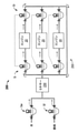
図2は、燃料と水の混合物の燃料消費量を計算するための他の燃料制御システム200を示す。図2に示すように、燃料制御システム200は、エンジン20に流体が行き来可能に連結された入口側流量計5iを含む。戻り側流量計5rもエンジン20に流体的に結合されている。また、エンジン20によって供給された未消費の燃料/水混合物を再循環させる燃料ラインからなる再循環器250も示されている。再循環器250は、再循環した燃料/水の混合物を消費すべきエンジン20に戻すように搬送する。入口側流量計51はエンジン20に流体が行き来可能に連結され、戻り側流量計5rは再循環器250を介して入口側流量計51に流体が行き来可能に連結されている。入口側流量計5i、戻り側流量計5rは、図1を参照して説明した混合物流量計5と同じである。水源側流量計5w及び燃料源側流量計5fも示されており、これらはミキサー230に流体が行き来可能に連結されている。ミキサー230は入口側流量計5i、戻り側流量計5rに流体が行き来可能に連結されている。
FIG. 2 shows another
水源側流量計5w及び燃料源側流量計5fは夫々、水及び燃料をミキサー230に供給する。水源側流量計5w及び燃料源側流量計5fは、ミキサー230に供給される水及び燃料の流量を測定する。測定された流量は、体積流量又は質量流量などの任意の適切な流量である。ミキサー230は、燃料と水を混合して燃料/水の混合物にし、燃料/水の混合物を入口側流量計5iに供給する。
The water source side flow meter 5w and the fuel source
入口側流量計5iは、ミキサー230から燃料/水の混合物を受け取り、燃料/水の混合物をエンジン20に供給する。入口側流量計5iによって提供される燃料/水の混合物は、エンジン20によって提供される未消費の燃料/水の混合物と混合される。理解されるように、入口側流量計5iは、エンジン20による消費量と同様である量の再混合された燃料/水の混合物をエンジン20に提供する。エンジン20による消費量はまた、入口側流量計5i及び戻り側流量計5rによって測定された流量の差と同様である。理解されるように、図2は、入口側流量計5i、エンジン20、および戻り側流量計5rの並列構成を示している。
The inlet-
燃料と水の混合物の燃料消費量を計算するための他の燃料制御システム300を示す。図3に示すように、燃料制御システム300は、バルブ320に流体が行き来可能に連結された燃料源310を含む。バルブ320は、バルブ320を介して供給される燃料を受け取るように構成されている第1のミキサー330に流体が行き来可能に連結されている。第1のミキサー330は、水源315に流体が行き来可能に連結されており、水源315によって提供された水を受け取るように構成されている。第1のミキサー330は、図3に示す混合物流量計5に流体が行き来可能に連結され、 燃料/水の混合物を混合物流量計5に供給するように構成されている。混合物流量計5は、供給された燃料/水の混合物を受け取って、その特性を測定するように構成されている。混合物流量計5は、第2のミキサー340に流体が行き来可能に連結されている。第2のミキサー340もエンジン20及び再循環器350に流体が行き来可能に連結されている。第2のミキサー340及び再循環器350はエンジン20に流体が行き来可能に連結されている。第2のミキサー340は、混合物流量計5によって供給された燃料/水の混合物と再循環器350からの再循環された燃料/水の混合物とを受け取り、混合して再混合した燃料/水の混合物にするように構成される。第2のミキサー340は、再混合された燃料/水の混合物をエンジン20に供給する。混合物流量計5、エンジン20、燃料源310、水源315、バルブ320、及び再循環器350は、コントローラ360に通信可能に連結されている。
Another
燃料源310及び水源315は、水源側流量計5w及び燃料源側流量計5fから構成されるかまたはそれらを含む。例えば、燃料源310及び水源315は、水源側流量計5w及び燃料源側流量計5fの入口に流体が行き来可能に連結されたタンクを含む。従って、水源側流量計5w及び燃料源側流量計5fは、コントローラ360に通信可能に連結される。水源側流量計5w及び燃料源側流量計5fはまた、燃料と水を第1のミキサー330に供給する。混合物流量計5は、入口側流量計5i、戻り側流量計5rを簡略化して表すことができる。混合物流量計5は、エンジン20による燃料/水の混合物の消費量を測定することができる。
The
第1及び第2のミキサー330、340は、燃料/水の混合物を保持し混合して均質な混合物にするように構成されたタンクであり得る。第1及び第2のミキサー330、340は、燃料を均質化するために様々な機構に依存する(rely on)。例えば、第1および第2のミキサー330、340は、燃料を均質化するために、例えば、環境振動、攪拌機などを使用することができる。しかし、他の実施形態では、任意の適切な構成を採用することができる。均質化されることによって、燃料/水の混合物は、均一に受け取った燃料と水とからなる。理解されるように、均一ではあるが、燃料及び水の濃度は経時的に変化し得る。
The first and
再循環器350は、エンジン20によって再循環される燃料/水の混合物を調整して、エンジン20によって消費されるように構成されてもよい。再循環器350は、圧力コントローラ、温度コントローラなどから構成することができるが、任意の適切な構成を採用することができる。再循環された燃料/水の混合物がエンジン20による使用に適しているように、圧力、温度などを制御するコントローラ360を含んで、エンジン20によって再循環された燃料/水の混合物を調整する。しかし、代替の実施形態において、コントローラ360によって制御されない構成要素を利用して、燃料/水の混合物を再調整する。
The
コントローラ360は、メモリ及びI/ Oポートに通信可能に結合されたプロセッサを含む回路基板であるが、代替の実施形態では任意の適切なコントローラを使用することができる。コントローラ360は、本明細書に記載の方法などの方法を実行して、図3に示す燃料制御システム300を通る燃料/水の混合物の流量を制御するソフトウェアを含むことができる。ソフトウェアはメモリに格納され、且つコントローラ360内のプロセッサによって実行されてもよい。コントローラ360は単一の回路基板として説明されているが、代替実施形態では、他のコントローラは、サブボード、モジュールなどの2つ以上の基板から構成されてもよい。
The
図3には示されていないが、燃料制御システム300は、温度または圧力センサ、流量制御バルブ、圧力調整器などの更なる構成要素から構成することができる。或いは、他の実施形態では図3に示す全ての要素を用いない。例えば、他の実施形態は、第1及び第2のミキサー330、340、再循環器350などを使用しよい。更に又はこれに代えて、図3の構成は他の構成を有してもよい。例えば、第1及び第2のミキサー330、340は、コントローラ360によって制御されるセンサ及び/又はアクチュエータを含み、第1及び第2のミキサー330、340によって受け取られた燃料/水の混合物を混合する。
Although not shown in FIG. 3, the
示されるように、コントローラ360は、I /Oポートを使用して混合物流量計5、エンジン20、燃料源310、水源315、バルブ320、及び再循環器350と通信するように構成されてもよい。I /Oポートは、例えば、シリアル、パラレル、パケットベースなどの任意の適切な通信手段を使用して通信するように構成され得る。コントローラ360は、例えば、I / Oポートを介して燃料源310、水源315、混合物流量計5からの流量測定値、エンジン20からの燃料消費量データ、バルブ320からのバルブ位置情報、及び再循環器350からの燃料/水の混合物の再循環データを受信することができる。コントローラ360はまた、バルブ開閉コマンドなどのコマンドをバルブ320に送信し、燃料調整コマンドを再循環器350に送信する。
As shown, the
コントローラ360内のプロセッサは、受信した流量データを使用して、混合物流量計5を通って流れる燃料/水の混合物の流量を計算する。コントローラ360内のプロセッサはまた、混合物流量計5によって提供される燃料/水の混合物の流量を使用して燃料/水の混合物の消費率を決定するように構成されてもよい。コントローラ360内のプロセッサはまた、I / Oポートを介してバルブ320を開閉するためのコマンドを送信する。コントローラ360はまた、コマンドがバルブ320に送信される時間を決定するためにプロセッサによって使用されるタイマを含み得る。以下により詳細に説明されるように、コントローラ360は、燃料/水の混合物の燃料消費量を計算することができる。
The processor in
燃料(水分を含まない)のカロリー量は、ISO-SFOC計算で使用され、下記の式(1)でQTEST として表示される。

SFOC =燃料消費率(g/kWh);
QTEST =試験中の燃料油の正味カロリー(発熱)量(MJ/kg);
QCONT = 工場受入れ試験と言及されるエンジンのベースライン特性評価中の燃料油の正味カロリー量(MJ/kg)
α =パワー調整係数
K =示されたパワーの比率;
Be =試験ベッドでの燃料油消費量(g/kWh); 及び
EDP = エンジン駆動ポンプ(g/kWh)
である。
用語「SFOC」が用いられるが、例えばBISOのような代替の用語が用いられ、これはまたISO3046-1に従った燃料油消費率とも言及される。
The calorie content of the fuel (not including water) is used in the ISO-SFOC calculation and is displayed as Q TEST in the following formula (1).
SFOC = fuel consumption rate (g / kWh);
Q TEST = Net calorie (calorific value) amount of fuel oil under test (MJ / kg);
Q CONT = Net calorie content of fuel oil during baseline characterization of engine referred to as factory acceptance test (MJ / kg)
α = power adjustment coefficient
K = ratio of power shown;
Be = Fuel oil consumption in test bed (g / kWh); and
EDP = engine drive pump (g / kWh)
Is.
The term "SFOC" is used, although alternative terms such as BISO are used, which are also referred to as fuel oil consumption rates in accordance with ISO 3046-1.
燃料/水の混合物が混合物流量計5に供給されると、以下の式(2)に見られるように、書き換えられた燃料/水の混合物のカロリー(発熱)量値が計算される。

QNEW = 燃料/水の混合物のカロリー量;
QFUEL =燃料油のカロリー量;
QWATER = 水のカロリー量;
mFUEL =燃料の質量流量濃度係数;及び
mWATER = 水の質量流量濃度係数
である。
When the fuel / water mixture is supplied to the
Q NEW = Calorie content of fuel / water mixture;
Q FUEL = calorie content of fuel oil;
Q WATER = water calorie content;
m FUEL = Fuel mass flow rate concentration factor; and
m WATER = mass flow rate concentration coefficient of water.
質量流量濃縮係数mFUEL及びmWATERは、夫々以下の式(3)及び式(4)にて計算される。

mFLOW FUEL =燃料の質量流量,
mFLOW
WATER =水の質量流量;及び
mFLOW TOTAL =燃料/水の質量流量
である。
The mass flow rate enrichment coefficients m FUEL and m WATER are calculated by the following equations (3) and (4), respectively.
m FLOW FUEL = mass flow rate of fuel,
m FLOW WATER = mass flow rate of water; and
m FLOW TOTAL = fuel / water mass flow rate.
燃料、水及び燃料/水の混合物は、図3を参照して記載した水源側流量計及び燃料源側流量計5w、5f及び混合物流量計5によって測定される。水源側流量計及び燃料源側流量計5w、5f及び混合物流量計5は測定された質量流量をコントローラ360に提供し、該コントローラは式(3)及び(4)を用いて質量流量濃度係数を計算し、式(2)を用いて燃料/水の混合物のカロリー量QNEW を計算し、燃料/水の混合物についてSFOC を計算する。
The fuel, water and fuel / water mixture are measured by the water source side flow meter and the fuel source
燃料/水の混合物についてSFOC を計算するとき、次の式(5)に示されるように、燃料/水の混合物のカロリー量QNEWがQTEST の代わりに使用される。

SFOCCORR=燃料/水の混合物について補正された燃料油消費率(g/kWh)
When calculating the SFOC for a fuel / water mixture, the calorie content Q NEW of the fuel / water mixture is used instead of Q TEST , as shown in equation (5) below.
SFOC CORR = fuel oil consumption rate corrected for fuel / water mixture (g / kWh)
従って、ベースラインまたは工場での受入れ試験SFOCでは燃料油の発熱量QCONTしか使用されていなかったが、修正された燃料油消費率SFOCCORRには水分のカロリー量が含まれている。 Therefore, while the baseline or factory acceptance test SFOC used only fuel oil calorific value Q CONT , the modified fuel oil consumption rate SFOC CORR includes the calorie content of water.
SFOC を修正するのに他の方法が用いられる。例えば、混合物についてSFOCを修正するための代替方法は、「消費される燃料質量」値を修正し、「燃料カロリー量」値を修正しないままにすることによる。「消費される燃料質量」の値は、全流体の燃焼測定値を使用する代わりに、燃料の混合物に添加された燃料のみを使用することによって修正される。或いは、水源側流量計及び燃料源側流量計5w、5f及び混合物流量計5による流量測定は体積流量測定であり得る。従って、燃料消費量の計算は、質量ではなく体積に基づいている。以下は、燃料/水の混合物の燃料消費量を計算する方法を示す。
Other methods are used to modify the SFOC. For example, an alternative way to modify the SFOC for a mixture is to modify the "fuel mass consumed" value and leave the "fuel calorie content" value uncorrected. The value of "fuel mass consumed" is modified by using only the fuel added to the mixture of fuels instead of using the combustion measurements of the whole fluid. Alternatively, the flow rate measurement by the water source side flow meter and the fuel source
方法
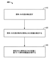
図4は、燃料と水の混合物の燃料消費量を計算する方法400を示す。方法400は、ステップ410において燃料/水の混合物を流すことによって開始する。燃料/水の混合物は、燃料源310によって供給される燃料油と水源315によって供給される水との混合物であり得るが、任意の適切な燃料/水の混合物を使用することができる。燃料/水の混合物は、第1のミキサー330内で混合され、混合物流量計5に供給されてもよい。燃料及び水の濃度は、例えば、燃料又は水の流量を制御することによって経時的に変化し得る。
Method FIG. 4 shows a
ステップ420にて、方法400は、燃料/水の混合物中の燃料と水の流量を測定する。燃料及び水の濃度が変化するために、燃料及び/又は水の測定された質量流量は変化する。水及び燃料の流量は、水源側流量計及び燃料源側流量計5w、5fによって測定することができる。水源側流量計及び燃料源側流量計5w、5fは、測定された燃料及び水の流量をコントローラ360に提供することができる。同様に、燃料/水の混合物の流量は、混合物流量計5によって測定され、コントローラ360に供給される。
At
ステップ430にて、方法400は、測定された燃料及び水の流量に基づいて燃料消費量を計算する。計算された燃料消費量は、式(5)を使用して計算され修正された燃料油消費率SFOCCORRであり得るが、任意の適切な燃料消費量計算が使用され得る。式(2)―(5)を参照すると、燃料/水の混合物の正味のカロリー量QNEWは、燃料と水の質量流量mFLOW FUEL、mFLOW WATERに基づいて計算することができる。修正された燃料油消費率SFOCCORRは、燃料/水の混合物の正味のカロリー量に基づいて計算することができる。
At
燃料消費量は連続して計算される。例えば、コントローラ360は水源側流量計及び燃料源側流量計5w、5fからmFLOW FUEL、mFLOW WATERを連続して受信し、混合物流量計5から総質量流量mFLOW TOTAL を連続して受信し、連続して且つ反復して修正された燃料油消費率SFOCCORRを計算する。更に又はこれに代えて、質量流量mFLOW FUEL、mFLOW WATER、mFLOW TOTAL 測定値間の時間遅延及び対応する燃料/水の混合物の消費量が含まれる。例えば、修正された燃料油消費率SFOCCORRは遅延分が相殺された測定データで計算されて、指示された出力Kとエンジン駆動ポンプEDPとの比、ならびに経時的に変化する他の任意の補正係数が、エンジン20によって実際に消費される燃料/水の混合物に対応することを確実にする。遅延は固定値でもよく、又は燃料/水の混合物の質量流量mFLOW TOTALに相関してもよい。
Fuel consumption is calculated continuously. For example, the
上記で説明したように、燃料制御システム300と方法400は、燃料/水の混合物の燃料消費量を計算する。燃料消費量は、燃料の質量流量及び水の質量流量に基づいて計算することができ、それらは水源側流量計及び燃料源側流量計5w、5fによって測定され得る。コントローラ360は、燃料/水の混合物中の燃料と水の両方のカロリー量を使用して燃料消費量を計算することができる。燃料/水の混合物の発熱量は、燃料/水の混合物中の燃料と水の質量濃度に基づく。例えば、修正された燃料油消費率SFOCCORRは、修正された燃料/水の混合物のカロリー量QNEWを用いて計算することができ、それによって燃料/水の混合物中の水のカロリー量を修正する。
As described above, the
その結果、エンジン20が燃料/水の混合物を消費しているとしても、エンジン20の燃料油消費率SFOCは、ISO規格(例えば、ISO 3046-1)に基づいて計算され、工場受入れ試験SFOCと比較されて、エンジンの現在のライフサイクル使用量を決定する。このISO規格比較はまた、エンジン製造業者によって販売されている予防メンテナンス/保守プログラムの有効性を証明するためにも使用することができる。修正された燃料油消費率SFOCCORRを使用すると、未修正の燃料油消費率SFOC計算を使用した場合よりも、予防メインテナンス/サービスプログラムの有効性をより正確に評価し得る。
As a result, even if the
上記の実施形態の詳細な説明は、本発明の範囲内であると本発明者らが考えているすべての実施形態の網羅的な説明ではない。実際、当業者であれば、上述の実施形態の特定の要素は、さらなる実施形態を作成するために様々に組み合わせるまたは削除されることができ、このようなさらなる実施形態は本明細書の範囲および教示に含まれることを認識すべきであろう。また、当業者には、上述の実施形態を全体的または部分的に組み合わせて、本明細書の範囲および教示内の追加の実施形態を作成することができることは明らかであろう。 The detailed description of the above embodiments is not an exhaustive description of all embodiments that the inventors consider to be within the scope of the present invention. In fact, one of ordinary skill in the art may combine or remove certain elements of the above embodiments in various ways to create further embodiments, such additional embodiments being within the scope of the present specification and. It should be recognized that it is included in the teaching. It will also be apparent to those skilled in the art that the above embodiments can be combined in whole or in part to create additional embodiments within the scope and teachings of this specification.
従って、特定の実施形態が本明細書において例示目的で記載されているが、当業者が認識するように、本明細書の範囲内で様々な均等な変更が可能である。本明細書で提供される教示は、上述され添付の図面に示される実施形態だけでなく、他の燃料/水の混合物の燃料消費計算にも適用することができる。従って、上記の実施形態の範囲は、以下の特許請求の範囲から決定されるべきである。 Accordingly, although certain embodiments are described herein for illustrative purposes, various even modifications are possible within the scope of this specification, as will be appreciated by those skilled in the art. The teachings provided herein can be applied not only to the embodiments shown above and in the accompanying drawings, but also to fuel consumption calculations for other fuel / water mixtures. Therefore, the scope of the above embodiment should be determined from the following claims.
Claims (15)
ミキサー(330)と、
ミキサー(330)に連結され、ミキサー(330)への燃料の流量を測定するように構成された燃料源(310)と、
ミキサー(330)に連結され、ミキサー(330)への水の流量を測定するように構成された水源(315)と、
ミキサー(330)に連結された混合物流量計(5)であって、ミキサー(330)から燃料と水の混合物を受け取って該混合物の特性を測定するように構成され、該混合物の特性は測定された燃料と水の混合物の流量を含む、混合物流量計(5)と、
燃料源(310)と水源(315)と混合物流量計(5)に通信可能に連結されたコントローラ(360)を備え、
コントローラ(360)は、測定された燃料の流量と測定された水の流量と、測定された燃料と水の混合物の流量に基づいて燃料消費率を計算するように構成される、燃料制御システム(300)。 A fuel control system (300) for calculating the fuel consumption rate of a mixture of fuel and water consumed by an engine .
Mixer (330) and
A fuel source (310) connected to the mixer (330) and configured to measure the flow rate of fuel to the mixer (330).
A water source (315) connected to the mixer (330) and configured to measure the flow rate of water to the mixer (330),
A mixture flowmeter (5) connected to a mixer (330), configured to receive a mixture of fuel and water from the mixer (330) and measure the characteristics of the mixture, the characteristics of the mixture being measured. A mixture flow meter (5), which contains the flow rate of the mixture of fuel and water.
Equipped with a controller (360) communicatively connected to a fuel source (310), a water source (315) and a mixture flow meter (5).
The controller (360) is a fuel control system (360) configured to calculate the fuel consumption rate based on the measured fuel flow rate and the measured water flow rate, and the measured fuel and water mixture flow rate. 300).

SFOC =燃料消費率(g/kWh);
QTEST =試験中に消費される燃料油の正味カロリー(発熱)量(MJ/kg);
QCONT =試験ベッドでのエンジンのベースライン特性評価中に消費される燃料油の正味カロリー量(MJ/kg)
α =パワー調整係数
K =示されたパワーの比率;
Be =試験ベッドでのエンジンのベースライン特性評価中に決定される燃料油消費率(g/kWh); 及び
EDP = エンジン駆動ポンプの燃料油消費率(g/kWh)
である、請求項1に記載の燃料制御システム(300)。 The controller (360), which is configured to calculate the fuel consumption rate during the test based on the measured fuel flow rate and the measured water flow rate and the measured fuel and water mixture flow rate, is as follows: It is configured to calculate the fuel consumption rate based on the formula,
SFOC = fuel consumption rate (g / kWh);
Q TEST = Net calorie (calorific value) amount of fuel oil consumed during the test (MJ / kg);
Q CONT = Net calorie content of fuel oil consumed during engine baseline characterization in test bed (MJ / kg)
α = power adjustment coefficient
K = ratio of power shown;
Be = Fuel oil consumption rate (g / kWh) determined during engine baseline characterization in test bed; and
EDP = Fuel oil consumption rate of engine drive pump (g / kWh)
The fuel control system (300) according to claim 1.

QNEW = 燃料と水の混合物のカロリー量;
QFUEL =燃料油のカロリー量;
QWATER = 水のカロリー量;
mFUEL =燃料の質量流量濃縮係数;及び
mWATER = 水の質量流量濃縮係数
である、請求項2に記載の燃料制御システム(300)。 The net calorie content (Q TEST ) of the fuel oil consumed during the test is rewritten as Q NEW in the following formula.
Q NEW = Calorie content of fuel and water mixture;
Q FUEL = calorie content of fuel oil;
Q WATER = water calorie content;
m FUEL = fuel mass flow enrichment factor; and
The fuel control system (300) according to claim 2, wherein m WATER = mass flow rate enrichment coefficient of water.
測定された燃料と水の混合物の流量を含む前記混合物の特性は、燃料と水の混合物の体積流量及び密度のうちの少なくとも1つを含む、請求項1に記載の燃料制御システム(300)。 The measured fuel flow rate and the measured water flow rate are volumetric flow rates, the fuel source (310) is further configured to measure the fuel density , and the water source (315) further measures the water density . Configured to
The fuel control system (300) of claim 1, wherein the characteristics of the mixture , including the measured flow rate of the fuel and water mixture, include at least one of the volumetric flow rate and density of the fuel and water mixture.
燃料と水の混合物を流すステップと、
燃料と水の混合物の流量を測定するステップと、
燃料と水の混合物となる燃料の流量と水の流量を測定するステップと、
測定された燃料の流量と測定された水の流量と測定された燃料と水の混合物の流量に基づいて燃料消費率を計算するステップを含む、方法。 A method of calculating the fuel consumption rate of a mixture of fuel and water consumed by an engine .
The step of flowing a mixture of fuel and water,
Steps to measure the flow rate of the fuel and water mixture,
Steps to measure the flow rate of fuel and the flow rate of water, which is a mixture of fuel and water,
A method comprising the step of calculating the fuel consumption rate based on the measured fuel flow rate and the measured water flow rate and the measured fuel and water mixture flow rate.

SFOC =燃料消費率(g/kWh);
QTEST =試験中に消費される燃料油の正味カロリー(発熱)量(MJ/kg);
QCONT =試験ベッドでのエンジンのベースライン特性評価中に消費される燃料油の正味カロリー量(MJ/kg)
α =パワー調整係数
K =示されたパワーの比率;
Be =試験ベッドでのエンジンのベースライン特性評価中に決定される燃料油消費率(g/kWh); 及び
EDP = エンジン駆動ポンプの燃料油消費率(g/kWh).
である、請求項9に記載の方法。 The step of calculating the fuel consumption rate based on the measured fuel flow rate and the measured water flow rate includes the step of calculating the fuel consumption rate under test based on the following formula.
SFOC = fuel consumption rate (g / kWh);
Q TEST = Net calorie (calorific value) amount of fuel oil consumed during the test (MJ / kg);
Q CONT = Net calorie content of fuel oil consumed during engine baseline characterization in test bed (MJ / kg)
α = power adjustment coefficient
K = ratio of power shown;
Be = Fuel oil consumption rate (g / kWh) determined during engine baseline characterization in test bed; and
EDP = Fuel oil consumption rate of engine drive pump (g / kWh).
The method according to claim 9.

QNEW = 燃料と水の混合物のカロリー量;
QFUEL =燃料油のカロリー量;
QWATER = 水のカロリー量;
mFUEL =燃料の質量流量濃縮係数;及び
mWATER = 水の質量流量濃縮係数
である、請求項10に記載の方法。 The net calorie content (Q TEST ) of the fuel oil consumed during the test is rewritten as Q NEW in the following formula.
Q NEW = Calorie content of fuel and water mixture;
Q FUEL = calorie content of fuel oil;
Q WATER = water calorie content;
m FUEL = fuel mass flow enrichment factor; and
The method of claim 10, wherein m WATER = mass flow rate concentration factor of water.
Applications Claiming Priority (3)
| Application Number | Priority Date | Filing Date | Title |
|---|---|---|---|
| US201662347999P | 2016-06-09 | 2016-06-09 | |
| US62/347,999 | 2016-06-09 | ||
| PCT/US2017/036058 WO2017214082A1 (en) | 2016-06-09 | 2017-06-06 | Fuel consumption calculation of a fuel and water mixture |
Related Child Applications (1)
| Application Number | Title | Priority Date | Filing Date |
|---|---|---|---|
| JP2020112541A Division JP2020172930A (en) | 2016-06-09 | 2020-06-30 | Fuel consumption calculation of fuel and water mixture |
Publications (2)
| Publication Number | Publication Date |
|---|---|
| JP2019519715A JP2019519715A (en) | 2019-07-11 |
| JP6992013B2 true JP6992013B2 (en) | 2022-01-13 |
Family
ID=59315690
Family Applications (2)
| Application Number | Title | Priority Date | Filing Date |
|---|---|---|---|
| JP2018564333A Active JP6992013B2 (en) | 2016-06-09 | 2017-06-06 | Fuel consumption calculation of a mixture of fuel and water |
| JP2020112541A Pending JP2020172930A (en) | 2016-06-09 | 2020-06-30 | Fuel consumption calculation of fuel and water mixture |
Family Applications After (1)
| Application Number | Title | Priority Date | Filing Date |
|---|---|---|---|
| JP2020112541A Pending JP2020172930A (en) | 2016-06-09 | 2020-06-30 | Fuel consumption calculation of fuel and water mixture |
Country Status (12)
| Country | Link |
|---|---|
| US (1) | US11441496B2 (en) |
| EP (1) | EP3469318B1 (en) |
| JP (2) | JP6992013B2 (en) |
| KR (1) | KR102135872B1 (en) |
| CN (1) | CN109219736A (en) |
| AU (1) | AU2017278274B2 (en) |
| BR (1) | BR112018073916B1 (en) |
| CA (1) | CA3027042C (en) |
| MX (1) | MX2018013603A (en) |
| RU (1) | RU2712989C1 (en) |
| SG (1) | SG11201810026VA (en) |
| WO (1) | WO2017214082A1 (en) |
Families Citing this family (2)
| Publication number | Priority date | Publication date | Assignee | Title |
|---|---|---|---|---|
| DE102020129992B4 (en) * | 2020-11-13 | 2022-09-08 | Volkswagen Aktiengesellschaft | Method for determining fuel consumption of a vehicle |
| CN112502865A (en) * | 2020-11-25 | 2021-03-16 | 江苏科技大学 | Dynamic intelligent emulsification system |
Family Cites Families (11)
| Publication number | Priority date | Publication date | Assignee | Title |
|---|---|---|---|---|
| JPH0233458A (en) * | 1988-07-25 | 1990-02-02 | Toyota Motor Corp | Operating method for diesel engine |
| US6612186B1 (en) | 2000-02-16 | 2003-09-02 | Micro Motion, Inc. | Mass fraction metering device |
| JP4864952B2 (en) * | 2008-09-30 | 2012-02-01 | 川崎重工業株式会社 | Diesel engine operation control method, operation control device, and diesel engine |
| DE102009015198A1 (en) * | 2009-03-31 | 2010-10-14 | Germanischer Lloyd Ag | A method for determining in real time a momentary energy transfer size of a ship |
| US20110265773A1 (en) | 2009-10-30 | 2011-11-03 | Bp Corporation North America Inc. | Composition and Method for Reducing NOx and Smoke Emissions From Diesel Engines at Minimum Fuel Consumption |
| WO2011053905A1 (en) | 2009-10-30 | 2011-05-05 | Cummins Inc. | Engine control techniques to account for fuel effects |
| JP5481310B2 (en) * | 2010-08-05 | 2014-04-23 | 川崎重工業株式会社 | Specific gravity monitoring control device and fuel supply device having the same |
| KR20120113321A (en) * | 2011-04-05 | 2012-10-15 | 무원엘에스 주식회사 | Emulsified fuel production and supply system of marine engine using chocked and swirl flow |
| KR101110015B1 (en) * | 2011-09-02 | 2012-04-18 | 이엔에프씨 주식회사 | Fuel supply system and emission reduction system for marine engine or boiler |
| WO2015030187A1 (en) | 2013-08-29 | 2015-03-05 | 独立行政法人水産大学校 | Water-mixture-fuel generation device |
| KR101463972B1 (en) * | 2014-01-10 | 2014-11-26 | 이지현 | Apparatus for manufacturing emulsified fuel and burning system using same |
-
2017
- 2017-06-06 AU AU2017278274A patent/AU2017278274B2/en active Active
- 2017-06-06 CA CA3027042A patent/CA3027042C/en active Active
- 2017-06-06 WO PCT/US2017/036058 patent/WO2017214082A1/en unknown
- 2017-06-06 EP EP17737931.0A patent/EP3469318B1/en active Active
- 2017-06-06 KR KR1020197000664A patent/KR102135872B1/en active IP Right Grant
- 2017-06-06 MX MX2018013603A patent/MX2018013603A/en unknown
- 2017-06-06 RU RU2018144363A patent/RU2712989C1/en active
- 2017-06-06 JP JP2018564333A patent/JP6992013B2/en active Active
- 2017-06-06 US US16/303,046 patent/US11441496B2/en active Active
- 2017-06-06 SG SG11201810026VA patent/SG11201810026VA/en unknown
- 2017-06-06 CN CN201780035531.6A patent/CN109219736A/en active Pending
- 2017-06-06 BR BR112018073916-2A patent/BR112018073916B1/en active IP Right Grant
-
2020
- 2020-06-30 JP JP2020112541A patent/JP2020172930A/en active Pending
Also Published As
| Publication number | Publication date |
|---|---|
| US20190301374A1 (en) | 2019-10-03 |
| AU2017278274A1 (en) | 2018-11-29 |
| MX2018013603A (en) | 2019-02-21 |
| RU2712989C1 (en) | 2020-02-03 |
| JP2020172930A (en) | 2020-10-22 |
| AU2017278274B2 (en) | 2019-08-15 |
| EP3469318A1 (en) | 2019-04-17 |
| CA3027042C (en) | 2021-07-06 |
| CN109219736A (en) | 2019-01-15 |
| WO2017214082A1 (en) | 2017-12-14 |
| BR112018073916B1 (en) | 2022-10-11 |
| EP3469318B1 (en) | 2022-03-02 |
| KR20190015557A (en) | 2019-02-13 |
| CA3027042A1 (en) | 2017-12-14 |
| SG11201810026VA (en) | 2018-12-28 |
| BR112018073916A2 (en) | 2019-02-26 |
| US11441496B2 (en) | 2022-09-13 |
| KR102135872B1 (en) | 2020-07-20 |
| JP2019519715A (en) | 2019-07-11 |
Similar Documents
| Publication | Publication Date | Title |
|---|---|---|
| JP2020172930A (en) | Fuel consumption calculation of fuel and water mixture | |
| EP2602547A1 (en) | Specific gravity monitoring control device and fuel supply apparatus provided with same | |
| US7428838B2 (en) | Calibration for an oil-consumption-measurement system | |
| US11592430B2 (en) | Method for estimating a combustion characteristic of a gas that may contain dihydrogen | |
| EP3723599A1 (en) | Breathing simulator and method for calibrating a gas analyzer with such a breathing simulator | |
| CN106194451A (en) | The method that multifuel engine and multifuel engine are run | |
| US7249530B2 (en) | Oil consumption simulating device | |
| CN111033016A (en) | Fuel metering circuit and method for compensating for fuel density variability | |
| CN101387633A (en) | Virtual fuel sensor for dual fuel tank applications | |
| JP6818756B2 (en) | How to characterize the flow period of a mixed fuel | |
| CN114199582A (en) | Online fuel consumption rate testing system and method for common rail type engine | |
| NO332544B1 (en) | System for monitoring and supplying additives in a fuel |
Legal Events
| Date | Code | Title | Description |
|---|---|---|---|
| A621 | Written request for application examination |
Free format text: JAPANESE INTERMEDIATE CODE: A621 Effective date: 20190108 |
|
| A977 | Report on retrieval |
Free format text: JAPANESE INTERMEDIATE CODE: A971007 Effective date: 20191113 |
|
| A131 | Notification of reasons for refusal |
Free format text: JAPANESE INTERMEDIATE CODE: A131 Effective date: 20191119 |
|
| A521 | Request for written amendment filed |
Free format text: JAPANESE INTERMEDIATE CODE: A523 Effective date: 20200127 |
|
| A02 | Decision of refusal |
Free format text: JAPANESE INTERMEDIATE CODE: A02 Effective date: 20200303 |
|
| A521 | Request for written amendment filed |
Free format text: JAPANESE INTERMEDIATE CODE: A523 Effective date: 20200630 |
|
| C60 | Trial request (containing other claim documents, opposition documents) |
Free format text: JAPANESE INTERMEDIATE CODE: C60 Effective date: 20200630 |
|
| A911 | Transfer to examiner for re-examination before appeal (zenchi) |
Free format text: JAPANESE INTERMEDIATE CODE: A911 Effective date: 20200710 |
|
| C21 | Notice of transfer of a case for reconsideration by examiners before appeal proceedings |
Free format text: JAPANESE INTERMEDIATE CODE: C21 Effective date: 20200714 |
|
| A912 | Re-examination (zenchi) completed and case transferred to appeal board |
Free format text: JAPANESE INTERMEDIATE CODE: A912 Effective date: 20200814 |
|
| C211 | Notice of termination of reconsideration by examiners before appeal proceedings |
Free format text: JAPANESE INTERMEDIATE CODE: C211 Effective date: 20200818 |
|
| C22 | Notice of designation (change) of administrative judge |
Free format text: JAPANESE INTERMEDIATE CODE: C22 Effective date: 20201027 |
|
| C13 | Notice of reasons for refusal |
Free format text: JAPANESE INTERMEDIATE CODE: C13 Effective date: 20210105 |
|
| C22 | Notice of designation (change) of administrative judge |
Free format text: JAPANESE INTERMEDIATE CODE: C22 Effective date: 20210209 |
|
| A521 | Request for written amendment filed |
Free format text: JAPANESE INTERMEDIATE CODE: A523 Effective date: 20210330 |
|
| C22 | Notice of designation (change) of administrative judge |
Free format text: JAPANESE INTERMEDIATE CODE: C22 Effective date: 20210413 |
|
| C13 | Notice of reasons for refusal |
Free format text: JAPANESE INTERMEDIATE CODE: C13 Effective date: 20210601 |
|
| A521 | Request for written amendment filed |
Free format text: JAPANESE INTERMEDIATE CODE: A523 Effective date: 20210826 |
|
| C23 | Notice of termination of proceedings |
Free format text: JAPANESE INTERMEDIATE CODE: C23 Effective date: 20211005 |
|
| C03 | Trial/appeal decision taken |
Free format text: JAPANESE INTERMEDIATE CODE: C03 Effective date: 20211109 |
|
| C30A | Notification sent |
Free format text: JAPANESE INTERMEDIATE CODE: C3012 Effective date: 20211109 |
|
| A61 | First payment of annual fees (during grant procedure) |
Free format text: JAPANESE INTERMEDIATE CODE: A61 Effective date: 20211208 |
|
| R150 | Certificate of patent or registration of utility model |
Ref document number: 6992013 Country of ref document: JP Free format text: JAPANESE INTERMEDIATE CODE: R150 |
|
| S802 | Written request for registration of partial abandonment of right |
Free format text: JAPANESE INTERMEDIATE CODE: R311802 |
|
| R350 | Written notification of registration of transfer |
Free format text: JAPANESE INTERMEDIATE CODE: R350 |