JP6991895B2 - CAN frame relay device, measurement system, recording system and CAN frame relay method - Google Patents

CAN frame relay device, measurement system, recording system and CAN frame relay method Download PDF

Info

Publication number
JP6991895B2
JP6991895B2 JP2018039508A JP2018039508A JP6991895B2 JP 6991895 B2 JP6991895 B2 JP 6991895B2 JP 2018039508 A JP2018039508 A JP 2018039508A JP 2018039508 A JP2018039508 A JP 2018039508A JP 6991895 B2 JP6991895 B2 JP 6991895B2
Authority
JP
Japan
Prior art keywords
frame
serial bus
voltage
unit
data
Prior art date
Legal status (The legal status is an assumption and is not a legal conclusion. Google has not performed a legal analysis and makes no representation as to the accuracy of the status listed.)
Active
Application number
JP2018039508A
Other languages
Japanese (ja)
Other versions
JP2019153995A (en
Inventor
浩一 柳沢
Current Assignee (The listed assignees may be inaccurate. Google has not performed a legal analysis and makes no representation or warranty as to the accuracy of the list.)
Hioki EE Corp
Original Assignee
Hioki EE Corp
Priority date (The priority date is an assumption and is not a legal conclusion. Google has not performed a legal analysis and makes no representation as to the accuracy of the date listed.)
Filing date
Publication date
Application filed by Hioki EE Corp filed Critical Hioki EE Corp
Priority to JP2018039508A priority Critical patent/JP6991895B2/en
Publication of JP2019153995A publication Critical patent/JP2019153995A/en
Application granted granted Critical
Publication of JP6991895B2 publication Critical patent/JP6991895B2/en
Active legal-status Critical Current
Anticipated expiration legal-status Critical

Links

Images

Landscapes

  • Small-Scale Networks (AREA)

Description

本発明は、第1のシリアルバスを介して伝送されているCANフレームを読み取って第2のシリアルバスに出力するCANフレーム中継装置およびCANフレーム中継方法、そのようなCANフレーム中継装置と測定装置とを備えた測定システム、並びにそのようなCANフレーム中継装置と記録装置とを備えた記録システムに関するものである。 The present invention includes a CAN frame relay device and a CAN frame relay method that reads a CAN frame transmitted via a first serial bus and outputs it to a second serial bus, such a CAN frame relay device and a measuring device. The present invention relates to a measurement system including, and a recording system including such a CAN frame relay device and a recording device.

例えば、自動車の開発者(自動車製造メーカ)や、自動者用アフターパーツの開発者などは、実使用を想定した各種環境下で自動車を走行させて走行性能や搭載機器の動作状態を評価する作業を繰り返し行っている。そのような評価の作業のなかには、車両に常設の各種機器からどのようなCANフレームが出力されているかのモニタリング(CAN通信用のシリアルバスを介して伝送されているCANフレームに基づく各種パラメータの測定処理や、伝送されているCANフレームの記録処理など)を行う評価項目が存在する。 For example, automobile developers (automobile manufacturers) and developers of after-parts for automatic users drive automobiles in various environments assuming actual use and evaluate the driving performance and operating conditions of on-board equipment. Is repeated. In such evaluation work, monitoring what kind of CAN frame is output from various devices permanently installed in the vehicle (measurement of various parameters based on the CAN frame transmitted via the serial bus for CAN communication). There are evaluation items for processing (processing, recording processing of transmitted CAN frames, etc.).

一方、下記の特許文献には、CAN通信用のシリアルバス(車内LAN)を介して伝送されている各種CANフレーム(制御データ)を収集して記録可能に構成された車両データ収集装置(以下、単に「収集装置」ともいう)の発明が開示されている。この収集装置は、故障診断やメンテナンスなどを目的として外部機器を接続可能にシリアルバスに設けられているダイアグコネクタ(診断機器接続用コネクタ:以下、単に「コネクタ」ともいう)に接続可能に構成されている。また、この収集装置は、収集したCANフレームをパーソナルコンピュータや分析装置などの解析装置にUSBケーブル等を介して出力することができるように構成されている。 On the other hand, the following patent documents include a vehicle data collection device (hereinafter referred to as a vehicle data collection device) configured to collect and record various CAN frames (control data) transmitted via a serial bus (in-vehicle LAN) for CAN communication. The invention of (simply also referred to as a "collector") is disclosed. This collection device is configured to be connectable to a diagnostic connector (connector for connecting diagnostic equipment: hereinafter simply referred to as "connector") provided on the serial bus so that external equipment can be connected for the purpose of failure diagnosis and maintenance. ing. Further, this collecting device is configured so that the collected CAN frames can be output to an analysis device such as a personal computer or an analysis device via a USB cable or the like.

この収集装置では、上記のコネクタに接続することでコネクタを介して供給される電源によって動作し、イグニッションスイッチの操作に連動してシリアルバスからのCANフレームの収集の開始/停止を自動的に実行する構成が採用されている。また、この収集装置では、USBケーブルを介して解析装置(パーソナルコンピュータ等)が接続されたときに、収集済のCANフレームを解析装置に対して自動的に出力する構成が採用されている。これにより、収集装置によって収集した各種CANフレームを解析装置に転送して解析装置においてCANフレームの内容を解析することにより、走行時等における各種機器の動作状態を評価することが可能となる。 This collection device is operated by the power supplied through the connector by connecting to the above connector, and automatically starts / stops the collection of CAN frames from the serial bus in conjunction with the operation of the ignition switch. The configuration is adopted. Further, in this collecting device, when an analysis device (personal computer or the like) is connected via a USB cable, a configuration is adopted in which the collected CAN frames are automatically output to the analysis device. This makes it possible to evaluate the operating state of various devices during traveling or the like by transferring the various CAN frames collected by the collecting device to the analysis device and analyzing the contents of the CAN frames in the analysis device.

特開2008-70133号公報(第4-11頁、第1-17図)Japanese Unexamined Patent Publication No. 2008-70133 (Pages 4-11, Fig. 1-17)

ところが、上記特許文献に開示の収集装置には、以下のような解決すべき問題点が存在する。具体的には、上記の収集装置では、コネクタを介して接続したシリアルバスから各種のCANフレームを収集する構成が採用されている。 However, the collection device disclosed in the above patent document has the following problems to be solved. Specifically, the above-mentioned collecting device adopts a configuration in which various CAN frames are collected from a serial bus connected via a connector.

この場合、前述したように、シリアルバスに設けられているコネクタは、故障診断やメンテナンスなどを目的とする外部機器、すなわち、車両の開発者(製造メータ)が、車両の出荷後に故障診断やメンテナンスなどを目的として接続されることを想定している機器を接続するためのコネクタである。したがって、開発者が想定している診断機器等をコネクタに接続することは問題とはならないが、開発者が想定していない機器をコネクタに接続したときには、その車両において想定外のトラブルが生じる可能性がある。例えば、接続した機器の回路構成によっては、機器がノイズ源となってシリアルバスにノイズが流れ込み、シリアルバスを介して伝送されるべきCANフレームの伝送が阻害されたり、シリアルバスに接続されている車両搭載機器の誤動作を招いたりするおそれがある。 In this case, as described above, the connector provided on the serial bus is an external device for the purpose of failure diagnosis and maintenance, that is, the vehicle developer (manufacturing meter) performs failure diagnosis and maintenance after the vehicle is shipped. It is a connector for connecting devices that are supposed to be connected for the purpose of. Therefore, it is not a problem to connect the diagnostic equipment that the developer envisions to the connector, but when the equipment that the developer envisions is connected to the connector, unexpected troubles may occur in the vehicle. There is sex. For example, depending on the circuit configuration of the connected device, the device becomes a noise source and noise flows into the serial bus, which hinders the transmission of CAN frames that should be transmitted via the serial bus or is connected to the serial bus. There is a risk of causing malfunction of vehicle-mounted equipment.

また、自動車の分野においては、一般的には、上記のコネクタが運転席や助手席の足下に設置されている。このため、このコネクタを介してシリアルバスに接続しようとする機器が大型の場合には、コネクタの近傍に大型の機器を設置することから、運転操作の妨げとなったり、助手席の同乗者(評価作業の補助者)の動作の妨げとなったりする。また、接続しようとする機器が防振を要する機器の場合には、コネクタの近傍に設置すること自体が困難となる。このように、上記のコネクタを介してシリアルバスに各種の機器を接続する構成では、機器の設置場所の自由度が低いことに起因する各種の問題点が存在する。 Further, in the field of automobiles, the above connectors are generally installed under the feet of the driver's seat and the passenger seat. For this reason, if the device to be connected to the serial bus via this connector is large, the large device will be installed near the connector, which may interfere with driving operations or allow passengers in the passenger seat (passenger seat). It interferes with the operation of the evaluation work assistant). Further, when the device to be connected is a device that requires vibration isolation, it is difficult to install it in the vicinity of the connector. As described above, in the configuration in which various devices are connected to the serial bus via the above-mentioned connector, there are various problems due to the low degree of freedom in the installation location of the devices.

さらに、例えば車両やアフターパーツの開発に際しては、シリアルバスを介して伝送されている各種CANフレームを単に記録するだけでなく、評価すべき事項に応じて複数の装置をシリアルバスに接続し、いずれかの装置がCANフレームに基づいて演算した演算結果(演算結果を示すCANフレーム)を他の装置に転送してデータ処理させたり、シリアルバスを介して伝送されているCANフレームとは別個に新たに生成したCANフレーム(例えば、車両に搭載されている各種センサとは別個に取り付けたセンサを介して測定した測定値を示すCANフレーム)を他の装置に転送してデータ処理させたりする必要が生じることがある。この場合、上記のコネクタに分岐ケーブルや分岐コネクタを増設することで複数の装置をシリアルバスに接続することができる。 Furthermore, for example, when developing vehicles and after-parts, not only recording various CAN frames transmitted via the serial bus, but also connecting multiple devices to the serial bus according to the matters to be evaluated, eventually. The calculation result calculated by the device based on the CAN frame (CAN frame indicating the calculation result) is transferred to another device for data processing, or is newly added separately from the CAN frame transmitted via the serial bus. It is necessary to transfer the CAN frame generated in the above (for example, the CAN frame showing the measured value measured through the sensor mounted separately from the various sensors mounted on the vehicle) to another device for data processing. May occur. In this case, a plurality of devices can be connected to the serial bus by adding a branch cable or a branch connector to the above connector.

しかしながら、分岐ケーブル等を介してコネクタに接続した複数の外部機器間で上記のようにCANフレームを伝送させようとした場合には、そのCANフレームがコネクタを介して車両のシリアルバスに流れ込むこととなる。このため、外部機器間で多数のCANフレームを短い時間間隔で伝送させた場合には、シリアルバスに接続されている車両搭載機器間におけるCANフレームの伝送が阻害されるおそれがある。また、車両搭載機器間におけるCANフレームの伝送を阻害することのないように外部機器間でCANフレームを伝送させる場合には、少数のCANフレームを長い時間間隔で伝送させることしかできないため、評価に必要な詳細な情報を得るのが困難となる。 However, when the CAN frame is to be transmitted between a plurality of external devices connected to the connector via a branch cable or the like as described above, the CAN frame flows into the serial bus of the vehicle via the connector. Become. Therefore, when a large number of CAN frames are transmitted between external devices at short time intervals, the transmission of CAN frames between the vehicle-mounted devices connected to the serial bus may be hindered. In addition, when transmitting CAN frames between external devices so as not to interfere with the transmission of CAN frames between vehicle-mounted devices, only a small number of CAN frames can be transmitted at long time intervals, so this is an evaluation. It becomes difficult to obtain the necessary detailed information.

加えて、近年では、シリアルバスに接続されている各種ノードの動作を阻害する目的の悪意のCANフレームを出力する機器がコネクタに接続されたり、シリアルバスを介して伝送されているCANフレームを悪意の第三者に対して移動体通信網等を介して転送する機器がコネクタに接続されたりする事象が確認されている。このため、例えば車両の開発現場等においては、セキュリティの観点から、任意の外部機器を容易に接続可能な上記のコネクタをシリアルバスに配設しない構成の採用が検討されている。このような構成が採用された場合には、想定外の機器がシリアルバスに接続される可能性が低下する。しかしながら、前述の収集装置等をシリアルバスに接続するには、シリアルバスの信号線における絶縁被覆を剥がすなどして収集装置等を信号線の導線に対して直接接続する作業が必要となる。 In addition, in recent years, devices that output malicious CAN frames for the purpose of obstructing the operation of various nodes connected to the serial bus are connected to connectors, or CAN frames transmitted via the serial bus are malicious. It has been confirmed that a device that transfers to a third party via a mobile communication network or the like is connected to a connector. Therefore, for example, at a vehicle development site or the like, from the viewpoint of security, the adoption of a configuration in which the above-mentioned connector to which any external device can be easily connected is not arranged on the serial bus is being considered. When such a configuration is adopted, the possibility that an unexpected device is connected to the serial bus is reduced. However, in order to connect the above-mentioned collecting device or the like to the serial bus, it is necessary to directly connect the collecting device or the like to the lead wire of the signal line by removing the insulating coating on the signal line of the serial bus.

なお、自動車の分野における問題点について例示したが、自動車以外の分野、例えば、工場内の機械設備の分野においても、CAN通信用のシリアルバスを介して伝送されているCANフレームの取得に際して上記の問題と同様の問題が生じている。 Although the problems in the field of automobiles have been exemplified, the above-mentioned is also used in fields other than automobiles, for example, in the field of machinery and equipment in factories, when acquiring a CAN frame transmitted via a serial bus for CAN communication. A problem similar to the problem is occurring.

本発明は、かかる解決すべき問題点に鑑みてなされたものであり、第1のシリアルバス(中継すべきCANフレームを伝送しているシリアルバス)におけるCANフレームの伝送や、第1のシリアルバスに接続されているノードの動作を阻害することなく、第2のシリアルバス(CANフレームを中継すべきシリアルバス)に接続されているノード間で任意のCANフレームを確実かつ容易に伝送可能とし、かつ第2のシリアルバスに接続されているノードの設置場所の自由度を十分に向上させ得るCANフレーム中継装置、測定システム、記録システムおよびCANフレーム中継方法を提供することを主目的とする。 The present invention has been made in view of the problem to be solved, and the transmission of the CAN frame in the first serial bus (the serial bus transmitting the CAN frame to be relayed) and the first serial bus. Any CAN frame can be reliably and easily transmitted between the nodes connected to the second serial bus (the serial bus to which the CAN frame should be relayed) without disturbing the operation of the node connected to the CAN frame. Moreover, it is a main object to provide a CAN frame relay device, a measurement system, a recording system and a CAN frame relay method that can sufficiently improve the degree of freedom of the installation location of the node connected to the second serial bus.

上記目的を達成すべく、請求項1記載のCANフレーム中継装置は、CAN通信用の第1のシリアルバスを介して伝送されるCANフレームを当該第1のシリアルバスから読み取るCANフレーム読取部と、前記CANフレーム読取部によって読み取られた前記CANフレームを前記第1のシリアルバスとは異なるCAN通信用の第2のシリアルバスに出力するCANフレーム出力部とを備え、前記CANフレーム読取部は、前記CANフレームの伝送時に前記第1のシリアルバスにおけるフレーム伝送用導体に印加される電圧を当該フレーム伝送用導体に対して非接触で検出可能な非接触式電圧センサを有する電圧検出部と、当該電圧検出部によって検出された前記電圧の電圧レベルの変化に基づいて前記第1のシリアルバスを介して伝送された前記CANフレームを特定するフレーム特定部とを備えている。 In order to achieve the above object, the CAN frame relay device according to claim 1 includes a CAN frame reading unit that reads a CAN frame transmitted via a first serial bus for CAN communication from the first serial bus. The CAN frame reading unit includes a CAN frame output unit that outputs the CAN frame read by the CAN frame reading unit to a second serial bus for CAN communication different from the first serial bus, and the CAN frame reading unit is the CAN frame reading unit. A voltage detection unit having a non-contact type voltage sensor that can detect the voltage applied to the frame transmission conductor in the first serial bus in a non-contact manner with respect to the frame transmission conductor during CAN frame transmission, and the voltage. It includes a frame specifying unit that identifies the CAN frame transmitted via the first serial bus based on the change in the voltage level of the voltage detected by the detecting unit.

請求項2記載のCANフレーム中継装置は、請求項1記載のCANフレーム中継装置において、前記CANフレーム読取部によって前記第1のシリアルバスから読み取られた前記CANフレームのフレームIDを予め規定された変更規則に従って変更し、変更後の当該CANフレームを前記CANフレーム出力部から前記第2のシリアルバスに出力させるID変更処理部を備えている。 The CAN frame relay device according to claim 2 is the CAN frame relay device according to claim 1, in which the frame ID of the CAN frame read from the first serial bus by the CAN frame reader is changed in advance. It is provided with an ID change processing unit that changes according to the rules and outputs the changed CAN frame from the CAN frame output unit to the second serial bus.

請求項3記載のCANフレーム中継装置は、請求項1または2記載のCANフレーム中継装置において、前記CANフレーム読取部によって前記第1のシリアルバスから読み取られた前記CANフレームのうちの予め規定された条件を満たす当該CANフレームを前記CANフレーム出力部から前記第2のシリアルバスに出力させるフィルタリング処理部を備えている。 The CAN frame relay device according to claim 3 is defined in advance among the CAN frames read from the first serial bus by the CAN frame reader in the CAN frame relay device according to claim 1 or 2. A filtering processing unit for outputting the CAN frame satisfying the conditions from the CAN frame output unit to the second serial bus is provided.

請求項4記載の測定システムは、請求項1から3のいずれかに記載のCANフレーム中継装置と、前記第2のシリアルバスに接続されると共に、前記CANフレーム読取部によって前記第1のシリアルバスから読み取られて前記CANフレーム出力部によって前記第2のシリアルバスに出力された前記CANフレームに基づいて予め規定された被測定量を測定可能に構成された測定装置とを備えている。 The measuring system according to claim 4 is connected to the CAN frame relay device according to any one of claims 1 to 3 and the second serial bus, and is connected to the first serial bus by the CAN frame reading unit. It is provided with a measuring device configured to be able to measure a pre-defined measure measure based on the CAN frame read from the CAN frame and output to the second serial bus by the CAN frame output unit.

請求項5記載の記録システムは、請求項1から3のいずれかに記載のCANフレーム中継装置と、前記第2のシリアルバスに接続されると共に、前記CANフレーム読取部によって前記第1のシリアルバスから読み取られて前記CANフレーム出力部によって前記第2のシリアルバスに出力された前記CANフレーム、および当該CANフレームに基づいて予め規定された演算処理によって演算した演算結果の少なくとも一方を記録可能に構成された記録装置とを備えている。 The recording system according to claim 5 is connected to the CAN frame relay device according to any one of claims 1 to 3 and the second serial bus, and is connected to the first serial bus by the CAN frame reader. Can record at least one of the CAN frame read from and output to the second serial bus by the CAN frame output unit and the calculation result calculated by a predetermined calculation process based on the CAN frame. It is equipped with a recording device.

請求項6記載のCANフレーム中継方法は、CAN通信用の第1のシリアルバスを介して伝送されるCANフレームを当該第1のシリアルバスから読み取ると共に、読み取った前記CANフレームを前記第1のシリアルバスとは異なるCAN通信用の第2のシリアルバスに出力する際に、前記CANフレームの伝送時に前記第1のシリアルバスにおけるフレーム伝送用導体に印加される電圧を当該フレーム伝送用導体に対して非接触で検出し、検出した前記電圧の電圧レベルの変化に基づいて前記第1のシリアルバスを介して伝送された前記CANフレームを特定する。 The CAN frame relay method according to claim 6 reads a CAN frame transmitted via a first serial bus for CAN communication from the first serial bus, and reads the read CAN frame into the first serial. When outputting to a second serial bus for CAN communication different from the bus, the voltage applied to the frame transmission conductor in the first serial bus during transmission of the CAN frame is applied to the frame transmission conductor. The CAN frame detected in a non-contact manner and transmitted via the first serial bus is specified based on the change in the voltage level of the detected voltage.

請求項7記載のCANフレーム中継方法は、請求項6記載のCANフレーム中継方法において、前記第1のシリアルバスから読み取った前記CANフレームのフレームIDを予め規定された変更規則に従って変更し、変更後の当該CANフレームを前記第2のシリアルバスに出力する。 The CAN frame relay method according to claim 7 is the CAN frame relay method according to claim 6, wherein the frame ID of the CAN frame read from the first serial bus is changed according to a predetermined change rule, and after the change. The CAN frame is output to the second serial bus.

請求項8記載のCANフレーム中継方法は、請求項6または7記載のCANフレーム中継方法において、前記第1のシリアルバスから読み取った前記CANフレームのうちの予め規定された条件を満たす当該CANフレームを前記第2のシリアルバスに出力するフィルタリング処理を実行する。 The CAN frame relay method according to claim 8 is the CAN frame relay method according to claim 6 or 7, wherein the CAN frame satisfying a predetermined condition among the CAN frames read from the first serial bus is used. The filtering process to be output to the second serial bus is executed.

請求項1記載のCANフレーム中継装置、および請求項6記載のCANフレーム中継方法では、CAN通信用の第1のシリアルバスを介して伝送されるCANフレームを第1のシリアルバスから読み取り、読み取ったCANフレームを第1のシリアルバスとは異なるCAN通信用の第2のシリアルバスに出力する際に、CANフレームの伝送時に第1のシリアルバスにおけるフレーム伝送用導体に印加される電圧をフレーム伝送用導体に対して非接触で検出し、検出した電圧の電圧レベルの変化に基づいて第1のシリアルバスを介して伝送されたCANフレームを特定する。 In the CAN frame relay device according to claim 1 and the CAN frame relay method according to claim 6, a CAN frame transmitted via the first serial bus for CAN communication is read from the first serial bus and read. When outputting a CAN frame to a second serial bus for CAN communication different from the first serial bus, the voltage applied to the frame transmission conductor in the first serial bus during transmission of the CAN frame is used for frame transmission. It detects non-contact with the conductor and identifies the CAN frame transmitted via the first serial bus based on the change in the voltage level of the detected voltage.

また、請求項4記載の測定システムでは、請求項1から3のいずれかに記載のCANフレーム中継装置と、第2のシリアルバスに接続されると共に、CANフレーム読取部によって第1のシリアルバスから読み取られてCANフレーム出力部によって第2のシリアルバスに出力されたCANフレームに基づいて予め規定された被測定量を測定可能に構成された測定装置とを備えている。さらに、請求項5記載の記録システムでは、請求項1から3のいずれかに記載のCANフレーム中継装置と、第2のシリアルバスに接続されると共に、CANフレーム読取部によって第1のシリアルバスから読み取られてCANフレーム出力部によって第2のシリアルバスに出力されたCANフレーム、およびCANフレームに基づいて予め規定された演算処理によって演算した演算結果の少なくとも一方を記録可能に構成された記録装置とを備えている。 Further, in the measurement system according to claim 4, the CAN frame relay device according to any one of claims 1 to 3 is connected to the second serial bus, and the CAN frame reading unit is used to connect the CAN frame repeater to the first serial bus. It is provided with a measuring device configured to be able to measure a pre-defined measured quantity based on a CAN frame that has been read and output to a second serial bus by a CAN frame output unit. Further, in the recording system according to claim 5, the CAN frame relay device according to any one of claims 1 to 3 is connected to the second serial bus, and the CAN frame reading unit is used to connect the CAN frame repeater to the first serial bus. A recording device configured to be able to record at least one of a CAN frame that has been read and output to the second serial bus by the CAN frame output unit and an operation result calculated by a predetermined arithmetic process based on the CAN frame. It is equipped with.

したがって、請求項1記載のCANフレーム中継装置、および請求項6記載のCANフレーム中継方法、並びに請求項4記載の測定システム、および請求項5記載の記録システムによれば、第1のシリアルバスの信号線に非接触式電圧センサを装着する簡易な作業を行うことで第1のシリアルバスからCANフレームを読み取って第2のシリアルバスに出力する(CANフレームを中継する)ことができる。これにより、第1のシリアルバスにコネクタが配設されていなくても、第2のシリアルバスに中継すべきCANフレームを読み取ることができ、また、第1のシリアルバスにコネクタが配設されている場合においても、コネクタの配設場所の近傍に限定されることなく、第1のシリアルバスの任意の場所においてCANフレームを読み取ることができる。 Therefore, according to the CAN frame relay device according to claim 1, the CAN frame relay method according to claim 6, the measurement system according to claim 4, and the recording system according to claim 5, the first serial bus. By simply attaching a non-contact voltage sensor to the signal line, the CAN frame can be read from the first serial bus and output to the second serial bus (relaying the CAN frame). As a result, the CAN frame to be relayed to the second serial bus can be read even if the connector is not arranged on the first serial bus, and the connector is arranged on the first serial bus. Even in this case, the CAN frame can be read at any place on the first serial bus without being limited to the vicinity of the place where the connector is arranged.

また、CANフレーム中継装置や、CANフレーム中継装置が接続されている第2のシリアルバスに接続された測定装置および記録装置等においてノイズが生じたとしても、このノイズがCANフレーム中継装置を介して第1のシリアルバスの伝送用導体に流れ込む事態が回避されるため、第1のシリアルバスを介してのCANフレームの伝送や、第1のシリアルバスに接続されている各ノードの動作が阻害される事態を招くことなく、第1のシリアルバスからCANフレームを読み取ることができる。さらに、第1のシリアルバスの信号線における伝送用導体に対して非接触の状態で非接触式電圧センサを介してCANフレームを読み取ることで、信号線から非接触式電圧センサを取り外した状態においても、非接触式電圧センサを装着する以前の状態と同様の絶縁状態を維持することができる。 Further, even if noise is generated in the CAN frame relay device, the measuring device and the recording device connected to the second serial bus to which the CAN frame relay device is connected, this noise is transmitted through the CAN frame relay device. Since the situation of flowing into the transmission conductor of the first serial bus is avoided, the transmission of the CAN frame via the first serial bus and the operation of each node connected to the first serial bus are hindered. The CAN frame can be read from the first serial bus without causing a situation. Further, by reading the CAN frame through the non-contact voltage sensor in a non-contact state with respect to the transmission conductor in the signal line of the first serial bus, the non-contact voltage sensor is removed from the signal line. However, it is possible to maintain the same insulation state as before the non-contact voltage sensor is attached.

また、第2のシリアルバスに接続された機器(測定装置等)において新たに生成されて第2のシリアルバスを介して伝送されるCANフレーム(第1のシリアルバスから中継されたCANフレームを除くCANフレーム)が第2のシリアルバスから第1のシリアルバスに伝送されることがないため、第1のシリアルバスにおいて伝送されるべきCANフレームの伝送が阻害されたり、第1のシリアルバスに接続されている各ノードの動作が阻害されたりする事態を招くことなく、第2のシリアルバスに接続された機器は、第2のシリアルバスを介して任意のCANフレームを自由に伝送させることができる。さらに、CANフレーム中継装置については、第1のシリアルバスからのCANフレームの読み取りが可能な任意の場所に設置することができ、また、測定装置および記録装置については、第2のシリアルバスに接続可能な任意の場所に設置することができるため、これらの設置場所についての自由度を十分に向上させることができる。 Further, the CAN frame newly generated in the device (measuring device, etc.) connected to the second serial bus and transmitted via the second serial bus (excluding the CAN frame relayed from the first serial bus). Since the CAN frame) is not transmitted from the second serial bus to the first serial bus, the transmission of the CAN frame to be transmitted in the first serial bus is hindered or connected to the first serial bus. A device connected to the second serial bus can freely transmit an arbitrary CAN frame via the second serial bus without causing a situation in which the operation of each node is disturbed. .. Further, the CAN frame relay device can be installed at any place where the CAN frame can be read from the first serial bus, and the measuring device and the recording device are connected to the second serial bus. Since it can be installed in any possible place, the degree of freedom regarding these installation places can be sufficiently improved.

請求項2記載のCANフレーム中継装置、および請求項7記載のCANフレーム中継方法によれば、第1のシリアルバスから読み取ったCANフレームのフレームIDを予め規定された変更規則に従って変更し、変更後のCANフレームを第2のシリアルバスに出力することにより、第1のシリアルバスにおける各CANフレームの伝送時に付与されたフレームIDによって示されている優先順位とは無関係に、第2のシリアルバスにおいて伝送されるべき優先順位のフレームIDを付与して各種のCANフレームを第2のシリアルバスにおいて伝送させることができるため、測定システムや記録システムにおける重要度が高いCANフレームの第2のシリアルバスにおける伝送が阻害される事態を好適に回避することができる。 According to the CAN frame relay device according to claim 2 and the CAN frame relay method according to claim 7, the frame ID of the CAN frame read from the first serial bus is changed according to a predetermined change rule, and after the change. By outputting the CAN frame of the above to the second serial bus, in the second serial bus regardless of the priority indicated by the frame ID given at the time of transmission of each CAN frame in the first serial bus. Since various CAN frames can be transmitted on the second serial bus by assigning a frame ID of the priority to be transmitted, the CAN frame is of high importance in the measurement system and the recording system in the second serial bus. It is possible to preferably avoid a situation in which transmission is obstructed.

請求項3記載のCANフレーム中継装置、および請求項8記載のCANフレーム中継方法によれば、第1のシリアルバスから読み取ったCANフレームのうちの予め規定された条件を満たすCANフレームを第2のシリアルバスに出力するフィルタリング処理を実行することにより、第2のシリアルバスに接続された各機器(測定装置や記録装置)において使用されることのないCANフレームが第1のシリアルバスから第2のシリアルバスに中継され、このCANフレームによって、第2のシリアルバスにおいて伝送されるべきCANフレーム(第2のシリアルバスに接続された各機器のいずれかが使用するCANフレーム)の伝送が阻害される事態を好適に回避することができる。 According to the CAN frame relay device according to claim 3 and the CAN frame relay method according to claim 8, the CAN frame that satisfies the predetermined condition among the CAN frames read from the first serial bus is the second CAN frame. By executing the filtering process to output to the serial bus, the CAN frame that is not used in each device (measuring device or recording device) connected to the second serial bus is transferred from the first serial bus to the second. It is relayed to the serial bus, and this CAN frame hinders the transmission of the CAN frame (the CAN frame used by any of the devices connected to the second serial bus) to be transmitted in the second serial bus. The situation can be avoided suitably.

自動車100およびデータ収集システム10の構成の一例を示す構成図である。It is a block diagram which shows an example of the structure of the automobile 100 and the data collection system 10. データ収集システム10における中継装置1の構成を示す構成図である。It is a block diagram which shows the structure of the relay device 1 in the data collection system 10. データ収集システム10における測定装置2の構成を示す構成図である。It is a block diagram which shows the structure of the measuring apparatus 2 in the data collection system 10. データ収集システム10における測定装置3の構成を示す構成図である。It is a block diagram which shows the structure of the measuring apparatus 3 in the data collection system 10. データ収集システム10におけるデータ処理装置4の構成を示す構成図である。It is a block diagram which shows the structure of the data processing apparatus 4 in the data collection system 10. データ収集システム10における記録装置5の構成を示す構成図である。It is a block diagram which shows the structure of the recording apparatus 5 in the data collection system 10. 他の実施の形態に係る電圧検出部60の構成を示す構成図である。It is a block diagram which shows the structure of the voltage detection part 60 which concerns on other embodiment.

以下、CANフレーム中継装置、測定システム、記録システムおよびCANフレーム中継方法の実施の形態について、添付図面を参照して説明する。 Hereinafter, embodiments of a CAN frame relay device, a measurement system, a recording system, and a CAN frame relay method will be described with reference to the accompanying drawings.

本件発明に係るCANフレーム中継装置およびCANフレーム中継方法は、各種CANフレームが伝送されているシリアルバスと、そのシリアルバスとは異なるシリアルバスとを並設してCANフレームを中継する各種の環境下で実施することができる。また、本件発明に係る測定システムおよび記録システムは、シリアルバスを伝送されているCANフレームを利用した測定処理や、CANフレームそのもの、およびCANフレームに基づいて生成される各種データの記録処理を行う各種の環境下で実施することができる。以下、一例として、図1に示す自動車100の評価を行うときにこれらを実施する例について説明する。 The CAN frame relay device and the CAN frame relay method according to the present invention are under various environments in which a serial bus in which various CAN frames are transmitted and a serial bus different from the serial bus are arranged side by side to relay the CAN frame. Can be carried out at. In addition, the measurement system and recording system according to the present invention perform measurement processing using CAN frames transmitted on a serial bus, CAN frames themselves, and various types of recording processing of various data generated based on CAN frames. It can be carried out in the environment of. Hereinafter, as an example, an example of carrying out these when evaluating the automobile 100 shown in FIG. 1 will be described.

自動車100は、「CAN通信用の第1のシリアルバス」に相当するシリアルバスSB1を備え、このシリアルバスSB1に、搭載機器の動作を制御するコントローラ(ECU)や、搭載機器等の動作状態を検出する検出器(センサー)などの複数のノード101a,101b・・(以下、区別しないときには「ノード101」ともいう)が接続されている。この場合、本例では、前述した「診断機器接続用コネクタ」に相当するコネクタがシリアルバスSB1に配設されておらず、既存の「CAN通信対応機器(診断機器接続用コネクタに接続可能な機器)」のシリアルバスSB1への接続が阻止されているものとする。 The automobile 100 includes a serial bus SB1 corresponding to a "first serial bus for CAN communication", and the serial bus SB1 is provided with an operating state of a controller (ECU) for controlling the operation of the mounted equipment, the mounted equipment, and the like. A plurality of nodes 101a, 101b, etc. (hereinafter, also referred to as "node 101" when not distinguished) such as a detector (sensor) for detection are connected. In this case, in this example, the connector corresponding to the above-mentioned "diagnostic device connection connector" is not arranged on the serial bus SB1, and the existing "CAN communication compatible device (device that can be connected to the diagnostic device connection connector"). ) ”Is assumed to be blocked from connecting to the serial bus SB1.

また、本例では、一例として、自動車100の空調機器の動作制御を目的として、バッテリー等の電源から空調機器に電力ラインLpを介して電力を供給させるときに、各ノード101のうちの1つである電源制御装置が、電力ラインLpに印加している電圧の電圧値を特定可能なCANフレームFcである電圧値データフレームFcv1や、電力ラインLpを流れる電流の電流値を特定可能なCANフレームFcである電流値データフレームFca1を、各ノード101のうちの他の1つである空調制御装置に対してシリアルバスSB1を介して伝送するものとする。 Further, in this example, as an example, one of the nodes 101 is used to supply electric power from a power source such as a battery to the air conditioner via the power line Lp for the purpose of controlling the operation of the air conditioner of the automobile 100. The voltage value data frame Fcv1, which is a CAN frame Fc that can specify the voltage value of the voltage applied to the power line Lp by the power supply control device, and the CAN frame that can specify the current value of the current flowing through the power line Lp. It is assumed that the current value data frame Fca1, which is an Fc, is transmitted to the air conditioning control device, which is the other one of the nodes 101, via the serial bus SB1.

さらに、本例では、一例として、自動車100における上記の空調機器の動作制御を目的として、各ノード101のうちの1つである空調制御装置が、車外温度センサからのセンサ信号に基づいて車外温度を特定すると共に、車内温度センサからのセンサ信号に基づいて車内温度を特定し、特定した車外温度や車内温度を特定可能なCANフレームFcである温度データフレームFct1を、各ノード101のうちの他の1つである主制御装置に対してシリアルバスSB1を介して伝送するものとする。 Further, in this example, as an example, for the purpose of controlling the operation of the above-mentioned air-conditioning device in the automobile 100, the air-conditioning control device, which is one of the nodes 101, has the outside-vehicle temperature based on the sensor signal from the outside-vehicle temperature sensor. The temperature data frame Fct1 which is a CAN frame Fc capable of specifying the vehicle interior temperature based on the sensor signal from the vehicle interior temperature sensor and specifying the specified vehicle exterior temperature and vehicle interior temperature is the other of the nodes 101. It is assumed that the signal is transmitted to the main control device, which is one of the above, via the serial bus SB1.

一方、同図に示すデータ収集システム10は、「測定システム」および「記録システム」の一例であって、「第1のシリアルバスとは異なるCAN通信用の第2のシリアルバス」に相当するシリアルバスSB2を備え、このシリアルバスSB2に、中継装置1、測定装置2,3、データ処理装置4および記録装置5などの各種の「ノード」が接続されて自動車100についての各種の評価に必要なデータを収集することができるように構成されている。なお、シリアルバスSB2に対して上記の構成要素1~5以外の「ノード」を接続することが可能であるが、本例のデータ収集システム10の構成要素以外の「ノード」については、図示および説明を省略する。 On the other hand, the data acquisition system 10 shown in the figure is an example of a "measurement system" and a "recording system", and is a serial corresponding to a "second serial bus for CAN communication different from the first serial bus". A bus SB2 is provided, and various "nodes" such as a relay device 1, a measuring device 2, 3, a data processing device 4, and a recording device 5 are connected to the serial bus SB2, which is necessary for various evaluations of the automobile 100. It is configured to be able to collect data. It is possible to connect "nodes" other than the above components 1 to 5 to the serial bus SB2, but the "nodes" other than the components of the data collection system 10 of this example are shown in the figure and The explanation is omitted.

この場合、前述の自動車100におけるシリアルバスSB1や、本例のデータ収集システム10におけるシリアルバスSB2は、「CANH(CAN high)」、「CANL(CAN low )」および「SG」などの複数のCAN通信用の信号線を備え、これらの信号線は、絶縁被覆された導線(「フレーム伝送用導体」の一例)を介して電気的信号を伝送可能に構成されている。この「CAN通信用のシリアルバス」を構成する信号線の種類および構造については公知のため、詳細な説明を省略する。 In this case, the serial bus SB1 in the automobile 100 described above and the serial bus SB2 in the data acquisition system 10 of this example have a plurality of CANs such as "CANH (CAN high)", "CANL (CAN low)" and "SG". A signal line for communication is provided, and these signal lines are configured to be capable of transmitting an electrical signal via an insulatingly coated conductor (an example of a "frame transmission conductor"). Since the types and structures of the signal lines constituting this "serial bus for CAN communication" are known, detailed description thereof will be omitted.

中継装置1は、「CANフレーム中継方法」に従ってシリアルバスSB1からシリアルバスSB2にCANフレームFcを中継する「CANフレーム中継装置」の一例であって、図2に示すように、電圧検出部11、操作部12、表示部13、信号出力部14、処理部15および記憶部16を備えている。 The relay device 1 is an example of a “CAN frame relay device” that relays a CAN frame Fc from the serial bus SB1 to the serial bus SB2 according to the “CAN frame relay method”, and as shown in FIG. 2, the voltage detection unit 11 It includes an operation unit 12, a display unit 13, a signal output unit 14, a processing unit 15, and a storage unit 16.

電圧検出部11は、「電圧検出部」に相当し、一例として、シリアルバスSB1の任意の部位に対して着脱自在なクランプ型の非接触式電圧センサ11a(「非接触式電圧センサ」の一例)を備えて処理部15と相俟って「CANフレーム読取部」を構成する。具体的には、電圧検出部11は、処理部15の制御に従い、後述するようにノード101からのシリアルバスSB1へのCANフレームFcの伝送時にシリアルバスSB1のフレーム伝送用導体に印加される電圧を非接触式電圧センサ11aを介してフレーム伝送用導体に対して非接触で検出し、検出した電圧の電圧レベルを特定可能な情報を処理部15に出力する。 The voltage detection unit 11 corresponds to a "voltage detection unit", and as an example, an example of a clamp-type non-contact voltage sensor 11a ("non-contact voltage sensor" that can be attached to and detached from any part of the serial bus SB1. ) Is provided to form a "CAN frame reading unit" in combination with the processing unit 15. Specifically, the voltage detection unit 11 follows the control of the processing unit 15, and as will be described later, the voltage applied to the frame transmission conductor of the serial bus SB1 when the CAN frame Fc is transmitted from the node 101 to the serial bus SB1. Is non-contactly detected with respect to the frame transmission conductor via the non-contact voltage sensor 11a, and information that can specify the voltage level of the detected voltage is output to the processing unit 15.

操作部12は、中継装置1の動作条件(主として、シリアルバスSB1からシリアルバスSB2へのCANフレームFcの中継条件)等の設定操作が可能な複数の操作スイッチを備え(図示せず)、スイッチ操作に応じた操作信号を処理部15に出力する。表示部13は、中継装置1の動作状態(CANフレームFcの中継状態)等を処理部15の制御下で表示する。信号出力部14は、処理部15と相俟って「CANフレーム出力部」を構成し、後述するように、電圧検出部11(非接触式電圧センサ11a)を介してシリアルバスSB1から読み取られたCANフレームFcを処理部15の制御下でシリアルバスSB2に出力する。 The operation unit 12 includes a plurality of operation switches capable of setting operations such as operating conditions of the relay device 1 (mainly relay conditions of the CAN frame Fc from the serial bus SB1 to the serial bus SB2) (not shown), and switches. The operation signal corresponding to the operation is output to the processing unit 15. The display unit 13 displays the operating state of the relay device 1 (relay state of the CAN frame Fc) and the like under the control of the processing unit 15. The signal output unit 14 constitutes a "CAN frame output unit" in combination with the processing unit 15, and is read from the serial bus SB1 via the voltage detection unit 11 (non-contact voltage sensor 11a) as described later. The CAN frame Fc is output to the serial bus SB2 under the control of the processing unit 15.

処理部15は、中継装置1を総括的に制御する。具体的には、処理部15は、「フレーム特定部」として機能し、自動車100のシリアルバスSB1におけるCANフレームFcの伝送時に電圧検出部11によって検出される電圧の「電圧レベル」の変化に基づき、シリアルバスSB1を伝送されているCANフレームFcを特定する処理を実行する。また、処理部15は、「フィルタリング処理部」として機能し、上記のように「フレーム特定部」として機能して特定した各CANフレームFcのうちの「予め規定された条件(一例として、利用者によって指定された条件)」を満たすCANフレームFcだけを信号出力部14からシリアルバスSB2に対して選択的に出力させる後述の「フィルタリング処理」を実行する。 The processing unit 15 comprehensively controls the relay device 1. Specifically, the processing unit 15 functions as a "frame identification unit" and is based on a change in the "voltage level" of the voltage detected by the voltage detection unit 11 during transmission of the CAN frame Fc in the serial bus SB1 of the automobile 100. , Performs a process of identifying the CAN frame Fc transmitted on the serial bus SB1. Further, the processing unit 15 functions as a "filtering processing unit", and "predetermined conditions (as an example, a user) of each CAN frame Fc specified by functioning as a" frame specifying unit "as described above. The "filtering process" described later is executed in which only the CAN frame Fc satisfying the "condition specified by the above)" is selectively output from the signal output unit 14 to the serial bus SB2.

さらに、処理部15は、「ID変更処理部」として機能し、シリアルバスSB1から読み取ったCANフレームFcについて、そのデータ本体の内容を変更することなく「予め規定された変更規則」に従ってフレームIDを変更し、ID変更後のCANフレームFcを信号出力部14からシリアルバスSB2に出力させる「ID変更処理」を実行する。なお、上記のように「フィルタリング処理」を実行する本例において、処理部15は、「フィルタリング処理」によってシリアルバスSB2に出力すべきと判別したCANフレームFcだけを対象として後述の「ID変更処理」を実行する。 Further, the processing unit 15 functions as an "ID change processing unit", and for the CAN frame Fc read from the serial bus SB1, the frame ID is changed according to the "predetermined change rule" without changing the content of the data body. The "ID change process" of changing and outputting the CAN frame Fc after the ID change from the signal output unit 14 to the serial bus SB2 is executed. In this example of executing the "filtering process" as described above, the processing unit 15 targets only the CAN frame Fc determined to be output to the serial bus SB2 by the "filtering process", and will be described later as "ID change process". Is executed.

記憶部16は、処理部15の動作プログラムや、CANフレームFc、CANフレームFcを特定するためのフレーム特定用データ、および利用者によって指定された上記の各種条件を示す条件データなどを記憶する。 The storage unit 16 stores the operation program of the processing unit 15, the CAN frame Fc, the frame specification data for specifying the CAN frame Fc, the condition data indicating the above-mentioned various conditions specified by the user, and the like.

測定装置2は、「電圧・電流測定装置」であって、一例として、自動車100の電力ラインLpに印加されている電圧の電圧値、および電力ラインLpを流れている電流の電流値を測定可能に構成されている。この測定装置2は、図3に示すように、電流測定部21、電圧測定部22、操作部23、表示部24、信号出力部25、処理部26および記憶部27を備えてシリアルバスSB2に接続されている。 The measuring device 2 is a "voltage / current measuring device", and as an example, can measure the voltage value of the voltage applied to the power line Lp of the automobile 100 and the current value of the current flowing through the power line Lp. It is configured in. As shown in FIG. 3, the measuring device 2 includes a current measuring unit 21, a voltage measuring unit 22, an operating unit 23, a display unit 24, a signal output unit 25, a processing unit 26, and a storage unit 27 in the serial bus SB2. It is connected.

電流測定部21は、一例として、任意の測定部位(本例では、電力ラインLp)に対して着脱自在なクランプ型の非接触式電流センサ21aを備えている。この電流測定部21は、自動車100において電力ラインLpを介して電力が供給されている状態で電力ラインLpの電力供給用導体を流れている電流の電流値を非接触式電流センサ21aを介して電力供給用導体に対して非接触で測定し、測定結果を示す電流値データDaを処理部26に出力する。 As an example, the current measuring unit 21 includes a clamp-type non-contact current sensor 21a that can be attached to and detached from an arbitrary measurement site (in this example, the power line Lp). The current measuring unit 21 measures the current value of the current flowing through the power supply conductor of the power line Lp in a state where power is supplied via the power line Lp in the automobile 100 via the non-contact current sensor 21a. The current value data Da indicating the measurement result is output to the processing unit 26 by measuring in a non-contact manner with respect to the power supply conductor.

電圧測定部22は、一例として、任意の測定部位(本例では、電力ラインLp)に対して着脱自在なクランプ型の非接触式電圧センサ22aを備えている。この電圧測定部22は、自動車100において電力ラインLpを介して電力が供給されている状態で電力ラインLpの電力供給用導体に印加されている電圧の電圧値を非接触式電圧センサ22aを介して電力供給用導体に対して非接触で測定し、測定結果を示す電圧値データDvを処理部26に出力する。 As an example, the voltage measuring unit 22 includes a clamp-type non-contact voltage sensor 22a that can be attached to and detached from an arbitrary measurement site (in this example, the power line Lp). The voltage measuring unit 22 transmits the voltage value of the voltage applied to the power supply conductor of the power line Lp in the state where power is supplied via the power line Lp in the automobile 100 via the non-contact type voltage sensor 22a. The voltage value data Dv indicating the measurement result is output to the processing unit 26 by measuring in a non-contact manner with respect to the power supply conductor.

操作部23は、測定装置2の動作条件(電流測定条件および電圧測定条件等)の設定操作が可能な複数の操作スイッチを備え(図示せず)、スイッチ操作に応じた操作信号を処理部26に出力する。表示部24は、測定装置2の動作状態や測定結果などを処理部26の制御下で表示する。信号出力部25は、後述するように処理部26によって生成される電流値データフレームFca2や電圧値データフレームFcv2などのCANフレームFcを処理部26の制御下でシリアルバスSB2に出力する。 The operation unit 23 includes a plurality of operation switches (not shown) capable of setting and operating the operating conditions (current measurement conditions, voltage measurement conditions, etc.) of the measuring device 2, and processes operation signals corresponding to the switch operations. Output to. The display unit 24 displays the operating state of the measuring device 2, the measurement result, and the like under the control of the processing unit 26. The signal output unit 25 outputs the CAN frame Fc such as the current value data frame Fca2 and the voltage value data frame Fcv2 generated by the processing unit 26 to the serial bus SB2 under the control of the processing unit 26, as will be described later.

処理部26は、測定装置2を総括的に制御する。具体的には、処理部26は、電流測定部21から出力される電流値データDaの電流値(電流測定部21の測定結果)や、電圧測定部22から出力される電圧値データDvの電圧値(電圧測定部22の測定結果)を表示部24に表示させる。また、処理部26は、電流値データDaに基づいて電流値データフレームFca2を生成すると共に、電圧値データDvに基づいて電圧値データフレームFcv2を生成する。 The processing unit 26 comprehensively controls the measuring device 2. Specifically, the processing unit 26 includes the current value of the current value data Da output from the current measurement unit 21 (measurement result of the current measurement unit 21) and the voltage of the voltage value data Dv output from the voltage measurement unit 22. The value (measurement result of the voltage measuring unit 22) is displayed on the display unit 24. Further, the processing unit 26 generates the current value data frame Fca2 based on the current value data Da, and also generates the voltage value data frame Fcv2 based on the voltage value data Dv.

さらに、処理部26は、生成した電流値データフレームFca2や電圧値データフレームFcv2を信号出力部25からシリアルバスSB2に出力させることで、電力ラインLpを介して供給されている電力の電力値をデータ処理装置4に演算(測定)させると共に、電流値データフレームFca2に基づいて特定される電流値データDa、電圧値データフレームFcv2に基づいて特定される電圧値データDv、および電流値データフレームFca2や電圧値データフレームFcv2自体を記録装置5によって記録させる。 Further, the processing unit 26 outputs the generated current value data frame Fca2 and voltage value data frame Fcv2 from the signal output unit 25 to the serial bus SB2 to obtain the power value of the power supplied via the power line Lp. The data processing device 4 is made to calculate (measure), and the current value data Da specified based on the current value data frame Fca2, the voltage value data Dv specified based on the voltage value data frame Fcv2, and the current value data frame Fca2. And the voltage value data frame Fcv2 itself is recorded by the recording device 5.

記憶部27は、処理部26の動作プログラムや、CANフレームFcを特定するためのフレーム特定用データ、および上記の各CANフレームFcなどを記憶する。 The storage unit 27 stores the operation program of the processing unit 26, the frame specification data for specifying the CAN frame Fc, the above-mentioned CAN frame Fc, and the like.

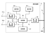
測定装置3は、「温度測定装置」であって、一例として、自動車100に取り付けられた温度センサ31a,32aを介して自動車100における任意の部位の温度を測定可能に構成されている。この測定装置3は、図4に示すように、温度測定部31,32、操作部33、表示部34、信号出力部35、処理部36および記憶部37を備えてシリアルバスSB2に接続される。 The measuring device 3 is a "temperature measuring device", and as an example, is configured to be capable of measuring the temperature of an arbitrary portion of the automobile 100 via the temperature sensors 31a and 32a attached to the automobile 100. As shown in FIG. 4, the measuring device 3 includes a temperature measuring unit 31, 32, an operating unit 33, a display unit 34, a signal output unit 35, a processing unit 36, and a storage unit 37, and is connected to the serial bus SB2. ..

温度測定部31,32は、一例として、任意の測定部位に対して着脱自在な温度センサ31a,32aを備えている。この温度測定部31,32は、自動車100において温度センサ31a,32aが装着された部位の温度を温度センサ31a,32aを介して測定し、測定結果を示す温度データDtを処理部36に出力する。この場合、本例では、一例として、温度センサ31aが自動車100の車外温度を検出可能な部位に装着され、温度センサ32aが自動車100の車内温度を検出可能な部位に装着されている。 As an example, the temperature measuring units 31 and 32 include temperature sensors 31a and 32a that can be attached to and detached from an arbitrary measuring portion. The temperature measuring units 31 and 32 measure the temperature of the portion where the temperature sensors 31a and 32a are mounted in the automobile 100 via the temperature sensors 31a and 32a, and output the temperature data Dt indicating the measurement result to the processing unit 36. .. In this case, in this example, as an example, the temperature sensor 31a is attached to a portion where the outside temperature of the automobile 100 can be detected, and the temperature sensor 32a is attached to the portion where the inside temperature of the automobile 100 can be detected.

操作部33は、測定装置3の動作条件(温度測定条件等)の設定操作が可能な複数の操作スイッチを備え(図示せず)、スイッチ操作に応じた操作信号を処理部36に出力する。表示部34は、測定装置3の動作状態や測定結果などを処理部36の制御下で表示する。信号出力部35は、後述するように処理部36によって生成される温度データフレームFct2などのCANフレームFcを処理部36の制御下でシリアルバスSB2に出力する。 The operation unit 33 includes a plurality of operation switches (not shown) capable of setting operation conditions (temperature measurement conditions, etc.) of the measuring device 3, and outputs an operation signal corresponding to the switch operation to the processing unit 36. The display unit 34 displays the operating state of the measuring device 3, the measurement result, and the like under the control of the processing unit 36. The signal output unit 35 outputs the CAN frame Fc such as the temperature data frame Fct2 generated by the processing unit 36 to the serial bus SB2 under the control of the processing unit 36, as will be described later.

処理部36は、測定装置3を総括的に制御する。具体的には、処理部36は、温度測定部31,32から出力される温度データDtに基づいて特定される温度(温度測定部31,32の測定結果)を表示部34に表示させる。また、処理部36は、温度データDtに基づいて温度データフレームFct2を生成する。さらに、処理部36は、生成した温度データフレームFct2を信号出力部35からシリアルバスSB2出力させることで、温度データフレームFct2に基づいて特定される温度データDt、および温度データフレームFct2自体を記録装置5によって記録させる。 The processing unit 36 comprehensively controls the measuring device 3. Specifically, the processing unit 36 causes the display unit 34 to display the temperature specified based on the temperature data Dt output from the temperature measuring units 31 and 32 (measurement results of the temperature measuring units 31 and 32). Further, the processing unit 36 generates the temperature data frame Fct2 based on the temperature data Dt. Further, the processing unit 36 outputs the generated temperature data frame Fct2 from the signal output unit 35 to the serial bus SB2, thereby recording the temperature data Dt specified based on the temperature data frame Fct2 and the temperature data frame Fct2 itself. Record by 5.

記憶部37は、処理部36の動作プログラムや、CANフレームFcを特定するためのフレーム特定用データ、および上記の各CANフレームFcなどを記憶する。 The storage unit 37 stores the operation program of the processing unit 36, the frame specification data for specifying the CAN frame Fc, the above-mentioned CAN frame Fc, and the like.

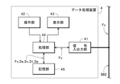
データ処理装置4は、「測定装置」の一例であって、シリアルバスSB2に接続されると共に、中継装置1によってシリアルバスSB1から読み取られてシリアルバスSB2に出力されたCANフレームFcや、測定装置2,3からシリアルバスSB2に出力されたCANフレームFcに基づき、「被測定量」の一例である「電力値」を測定可能に(演算可能に)構成されている。具体的には、図5に示すように、データ処理装置4は、信号入出力部41、操作部42、表示部43、処理部44および記憶部45を備えてシリアルバスSB2に接続されている。 The data processing device 4 is an example of a “measuring device”, which is a CAN frame Fc connected to the serial bus SB2, read from the serial bus SB1 by the relay device 1 and output to the serial bus SB2, and a measuring device. Based on the CAN frame Fc output from a few to the serial bus SB2, the "power value" which is an example of the "measured quantity" is configured to be measurable (calculable). Specifically, as shown in FIG. 5, the data processing device 4 includes a signal input / output unit 41, an operation unit 42, a display unit 43, a processing unit 44, and a storage unit 45, and is connected to the serial bus SB2. ..

信号入出力部41は、中継装置1によってシリアルバスSB1からシリアルバスSB2に中継されたCANフレームFc、および測定装置2,3によってシリアルバスSB2に出力されたCANフレームFcをシリアルバスSB2から取得して処理部44に出力する。また、信号入出力部41は、後述するように処理部44によって生成される電力値データフレームFcp12などのCANフレームFcを処理部44の制御下でシリアルバスSB2に出力する。操作部42は、データ処理装置4の動作条件(後述する電力値の測定条件等)の設定操作が可能な複数の操作スイッチを備え(図示せず)、スイッチ操作に応じた操作信号を処理部44に出力する。表示部43は、データ処理装置4の動作状態や測定結果などを処理部44の制御下で表示する。 The signal input / output unit 41 acquires the CAN frame Fc relayed from the serial bus SB1 to the serial bus SB2 by the relay device 1 and the CAN frame Fc output to the serial bus SB2 by the measuring devices 2 and 3 from the serial bus SB2. Is output to the processing unit 44. Further, the signal input / output unit 41 outputs the CAN frame Fc such as the power value data frame Fcp12 generated by the processing unit 44 to the serial bus SB2 under the control of the processing unit 44, as will be described later. The operation unit 42 includes a plurality of operation switches (not shown) capable of setting and operating the operating conditions (power value measurement conditions, etc. described later) of the data processing device 4, and processes operation signals corresponding to the switch operations. Output to 44. The display unit 43 displays the operating state of the data processing device 4, the measurement result, and the like under the control of the processing unit 44.

処理部44は、データ処理装置4を総括的に制御する。具体的には、処理部44は、信号入出力部41を介してシリアルバスSB2から取得したCANフレームFcのうちの中継装置1によって中継された電流値データフレームFca1や電圧値データフレームFcv1(シリアルバスSB1において伝送されていた電流値データフレームFca1や電圧値データフレームFcv1と同じ内容のCANフレームFc)に基づき、自動車100のノード101の1つである電源制御装置が測定した「電流値」および「電圧値」を特定し、特定した「電流値」および「電圧値」(すなわち、自動車100において測定された測定値)に基づいて電力ラインLpを介して供給されている電力の「電力値」を演算する処理(「予め規定された演算処理」の一例)を実行する。 The processing unit 44 comprehensively controls the data processing device 4. Specifically, the processing unit 44 is a current value data frame Fca1 or a voltage value data frame Fcv1 (serial) relayed by the relay device 1 among the CAN frame Fc acquired from the serial bus SB2 via the signal input / output unit 41. The "current value" measured by the power supply control device, which is one of the nodes 101 of the automobile 100, based on the current value data frame Fca1 and the voltage value data frame Fcv1 transmitted in the bus SB1. The "voltage value" is specified, and the "power value" of the power supplied through the power line Lp based on the specified "current value" and "voltage value" (that is, the measured value measured in the automobile 100). Is executed (an example of "predetermined arithmetic processing").

また、処理部44は、信号入出力部41を介してシリアルバスSB2から取得したCANフレームFcのうちの測定装置2から出力された電流値データフレームFca2に基づいて特定される「電流値」、および測定装置2から出力された電圧値データフレームFcv2に基づいて特定される「電圧値」(すなわち、データ収集システム10において測定した測定値)に基づき、電力ラインLpを介して供給されている電力の「電力値」を演算する処理を実行する。 Further, the processing unit 44 has a "current value" specified based on the current value data frame Fca2 output from the measuring device 2 among the CAN frame Fc acquired from the serial bus SB2 via the signal input / output unit 41. And the power supplied via the power line Lp based on the "voltage value" (that is, the measured value measured by the data acquisition system 10) specified based on the voltage value data frame Fcv2 output from the measuring device 2. Executes the process of calculating the "power value" of.

さらに、処理部44は、上記の両処理によって演算した電力値を表示部43に表示させると共に、演算した電力値を特定可能な電力値データフレームFcp12を生成する。また、処理部44は、生成した電力値データフレームFcp12を信号入出力部41からシリアルバスSB2に出力させることにより、後述するように、電力値データフレームFcp12に基づいて記録装置5において生成される電力値データDpおよび電力値データフレームFcp12自体を記録装置5に記録させる。 Further, the processing unit 44 displays the power value calculated by both of the above processes on the display unit 43, and generates a power value data frame Fcp12 capable of specifying the calculated power value. Further, the processing unit 44 outputs the generated power value data frame Fcp12 from the signal input / output unit 41 to the serial bus SB2, so that the processing unit 44 is generated in the recording device 5 based on the power value data frame Fcp12 as described later. The power value data Dp and the power value data frame Fcp12 itself are recorded in the recording device 5.

記憶部45は、処理部44の動作プログラム、CANフレームFcを特定するためのフレーム特定用データ、処理部15の演算結果、および上記の各CANフレームFcなどを記憶する。なお、本例のデータ収集システム10では、前述の中継装置1とデータ処理装置4とが相俟って「測定システム」が構成されている。 The storage unit 45 stores the operation program of the processing unit 44, the frame specifying data for specifying the CAN frame Fc, the calculation result of the processing unit 15, and each of the above-mentioned CAN frame Fc. In the data collection system 10 of this example, the above-mentioned relay device 1 and the data processing device 4 are combined to form a “measurement system”.

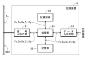
記録装置5は、「記録装置」の一例であって、シリアルバスSB2に接続されると共に、中継装置1によってシリアルバスSB1から読み取られてシリアルバスSB2に出力されたCANフレームFc、測定装置2,3やデータ処理装置4からシリアルバスSB2に出力されたCANフレームFc、およびそれらのCANフレームFcによって示されている各種の測定値データ(「CANフレームに基づいて予め規定された演算処理によって演算した演算結果」の一例)を記録可能に構成されている。具体的には、図6に示すように、記録装置5は、信号入出力部51、記録媒体52、データ入出力部53、処理部54および記憶部55を備えてシリアルバスSB2に接続されている。 The recording device 5 is an example of a “recording device”, and is a CAN frame Fc, a measuring device 2, which is connected to the serial bus SB2, is read from the serial bus SB1 by the relay device 1, and is output to the serial bus SB2. CAN frame Fc output from 3 and the data processing device 4 to the serial bus SB2, and various measured value data indicated by those CAN frame Fc ("calculated by a predetermined arithmetic process based on the CAN frame". An example of "calculation result") can be recorded. Specifically, as shown in FIG. 6, the recording device 5 includes a signal input / output unit 51, a recording medium 52, a data input / output unit 53, a processing unit 54, and a storage unit 55, and is connected to the serial bus SB2. There is.

信号入出力部51は、中継装置1によってシリアルバスSB1からシリアルバスSB2に中継されたCANフレームFc、および測定装置2,3やデータ処理装置4によってシリアルバスSB2に出力されたCANフレームFcをシリアルバスSB2から取得して処理部54に出力する。記録媒体52は、HDDやSSD等の大容量記録媒体で構成され、処理部54の制御下で各種のCANフレームFcや、CANフレームFcに基づいて特定される各種のデータ(電流値データDa、電圧値データDv、温度データDtおよび電力値データDp等)を記録する。データ入出力部53は、処理部54の制御に従い、外部装置(携帯型電子端末等)から入力された各データを処理部54に伝送して記録媒体52に記録させたり、記録媒体52に記録されているデータを外部装置に出力したりする。 The signal input / output unit 51 serializes the CAN frame Fc relayed from the serial bus SB1 to the serial bus SB2 by the relay device 1 and the CAN frame Fc output to the serial bus SB2 by the measuring devices 2 and 3 and the data processing device 4. It is acquired from the bus SB2 and output to the processing unit 54. The recording medium 52 is composed of a large-capacity recording medium such as an HDD or SSD, and under the control of the processing unit 54, various CAN frame Fcs and various data specified based on the CAN frame Fc (current value data Da, Voltage value data Dv, temperature data Dt, power value data Dp, etc.) are recorded. According to the control of the processing unit 54, the data input / output unit 53 transmits each data input from an external device (portable electronic terminal or the like) to the processing unit 54 and causes the recording medium 52 to record the data, or records the data on the recording medium 52. Output the data to an external device.

処理部54は、記録装置5を総括的に制御する。具体的には、処理部54は、中継装置1によってシリアルバスSB2に中継された電流値データフレームFca1に基づき、自動車100において測定された「電流値」を特定して電流値データDaを生成すると共に、測定装置2からシリアルバスSB2に出力された電流値データフレームFca2に基づき、データ収集システム10において測定された「電流値」を特定して電流値データDaを生成する。また、処理部54は、中継装置1によってシリアルバスSB2に中継された電圧値データフレームFcv1に基づき、自動車100において測定された「電圧値」を特定して電圧値データDvを生成すると共に、測定装置2からシリアルバスSB2に出力された電圧値データフレームFcv2に基づき、データ収集システム10において測定された「電圧値」を特定して電圧値データDvを生成する。 The processing unit 54 comprehensively controls the recording device 5. Specifically, the processing unit 54 specifies the "current value" measured in the automobile 100 and generates the current value data Da based on the current value data frame Fca1 relayed to the serial bus SB2 by the relay device 1. At the same time, based on the current value data frame Fca2 output from the measuring device 2 to the serial bus SB2, the "current value" measured by the data acquisition system 10 is specified and the current value data Da is generated. Further, the processing unit 54 specifies the "voltage value" measured in the automobile 100 based on the voltage value data frame Fcv1 relayed to the serial bus SB2 by the relay device 1, generates the voltage value data Dv, and measures the voltage value data Dv. Based on the voltage value data frame Fcv2 output from the device 2 to the serial bus SB2, the "voltage value" measured by the data acquisition system 10 is specified and the voltage value data Dv is generated.

さらに、処理部54は、中継装置1によってシリアルバスSB2に中継された温度データフレームFct1に基づき、自動車100において測定された「車外温度」や「車内温度」を特定して温度データDtを生成すると共に、測定装置2からシリアルバスSB2に出力された温度データフレームFct2に基づき、データ収集システム10において測定された「車外温度」や「車内温度」を特定して温度データDtを生成する。また、処理部54は、データ処理装置4からシリアルバスSB2に出力された電力値データフレームFcp12に基づき、自動車100において測定された「電流値」および「電圧値」に基づいてデータ収集システム10において演算された「電力値」、並びにデータ収集システム10において測定された「電流値」および「電圧値」に基づいてデータ収集システム10において演算された「電力値」を特定して電力値データDpを生成する。 Further, the processing unit 54 specifies the "outside temperature" and "inside temperature" measured in the automobile 100 based on the temperature data frame Fct1 relayed to the serial bus SB2 by the relay device 1 and generates the temperature data Dt. At the same time, the temperature data Dt is generated by specifying the "outside temperature" and "inside temperature" measured by the data acquisition system 10 based on the temperature data frame Fct2 output from the measuring device 2 to the serial bus SB2. Further, the processing unit 54 is in the data collection system 10 based on the "current value" and the "voltage value" measured in the automobile 100 based on the power value data frame Fcp12 output from the data processing device 4 to the serial bus SB2. The power value data Dp is specified by specifying the calculated "power value" and the "power value" calculated in the data collection system 10 based on the "current value" and the "voltage value" measured in the data collection system 10. Generate.

さらに、処理部54は、取得した各CANフレームFcや、生成した電流値データDa、電圧値データDv、温度データDtおよび電力値データDpなどを記録媒体52に記録させる。また、処理部54は、外部装置からデータ入出力部53を介して各種データが伝送されたときに、そのデータを記録媒体52に記録させると共に、外部装置からの要求に従って記録媒体52から各CANフレームFcや、生成した電流値データDa、電圧値データDv、温度データDtおよび電力値データDpなどを外部装置に対してデータ入出力部53から出力する。 Further, the processing unit 54 causes the recording medium 52 to record the acquired CAN frame Fc, the generated current value data Da, voltage value data Dv, temperature data Dt, power value data Dp, and the like. Further, when various data are transmitted from the external device via the data input / output unit 53, the processing unit 54 records the data on the recording medium 52, and each CAN is recorded from the recording medium 52 according to the request from the external device. The frame Fc, the generated current value data Da, the voltage value data Dv, the temperature data Dt, the power value data Dp, and the like are output from the data input / output unit 53 to the external device.

記憶部55は、処理部54の動作プログラムや、CANフレームFcを特定するためのフレーム特定用データなどを記憶する。なお、本例のデータ収集システム10では、前述の中継装置1およびデータ処理装置4と記録装置5とが相俟って「記録システム」が構成されている。 The storage unit 55 stores the operation program of the processing unit 54, frame specification data for specifying the CAN frame Fc, and the like. In the data collection system 10 of this example, the above-mentioned relay device 1, the data processing device 4, and the recording device 5 are combined to form a “recording system”.

次に、自動車100の評価の作業を例に挙げて、データ収集システム10(中継装置1、測定装置2,3、データ処理装置4および記録装置5)による各種処理の具体的な内容の一例を説明する。 Next, taking the work of evaluating the automobile 100 as an example, an example of specific contents of various processes by the data collection system 10 (relay device 1, measuring device 2, 3, data processing device 4 and recording device 5) is taken as an example. explain.

例えば、自動車100に搭載されている空調機器を評価するには、自動車100の搭載機器(いずれかのノード101)によって測定される「電流値」、「電圧値」、「車外温度」および「車内温度」と、自動車100の搭載機器とは別個独立して上記のパラメータを測定可能な測定装置(本例では、データ収集システム10の測定装置2,3等)によって測定される「電流値」、「電圧値」、「車外温度」および「車内温度」とを比較することで、搭載機器による測定結果が許容範囲内の値であるかや、空調機器が正常に動作しているかを判定することができる。 For example, in order to evaluate the air conditioning equipment mounted on the automobile 100, the "current value", the "voltage value", the "outside temperature" and the "inside the vehicle" measured by the onboard equipment (any node 101) of the automobile 100 are evaluated. "Temperature" and "current value" measured by a measuring device (in this example, measuring devices 2, 3, etc. of the data acquisition system 10) that can measure the above parameters independently of the on-board equipment of the automobile 100. By comparing the "voltage value", "outside temperature" and "inside temperature", it is possible to determine whether the measurement result by the on-board equipment is within the allowable range and whether the air conditioning equipment is operating normally. Can be done.

このような評価に際しては、まず、データ収集システム10における測定装置2,3、データ処理装置4および記録装置5を自動車100内の任意の場所に設置すると共に、図1に示すように、データ収集システム10専用の通信網を構成するシリアルバスSB2に対して各構成要素2~5をそれぞれ接続する。この際に、各構成要素2~5を接続するシリアルバスSB2を構成するケーブルについては、自動車100の任意の位置に引き回すことができる。したがって、設置可能なスペースの有無や、各センサ21a,22a,31a,32aの自動車100への装着の容易性などを考慮して、各構成要素2~5を自動車100内の任意の場所に自由に設置することができる。 In such an evaluation, first, the measuring devices 2 and 3, the data processing device 4 and the recording device 5 in the data collection system 10 are installed at arbitrary places in the automobile 100, and data collection is performed as shown in FIG. Each component 2 to 5 is connected to the serial bus SB2 constituting the communication network dedicated to the system 10. At this time, the cable constituting the serial bus SB2 connecting the components 2 to 5 can be routed to an arbitrary position of the automobile 100. Therefore, considering the presence or absence of a space that can be installed and the ease of mounting the sensors 21a, 22a, 31a, 32a on the automobile 100, each component 2 to 5 can be freely placed at any place in the automobile 100. Can be installed in.

次いで、測定装置2における電流測定部21の非接触式電流センサ21a、および電圧測定部22の非接触式電圧センサ22aを電気自動車100の電力ラインLpにそれぞれ装着する(電力ラインLpを非接触式電流センサ21aおよび非接触式電圧センサ22aによってそれぞれクランプする)。この際には、電力ラインLpの電力供給用導体と非接触式電流センサ21aの検出用コイルとが電線の絶縁被覆および非接触式電流センサ21aのケーシング等を介して近接した状態になると共に、電力ラインLpの電力供給用導体と非接触式電圧センサ22aの電極とが電線の絶縁被覆を介して近接した状態となり、電力供給用導体と非接触式電圧センサ22aの電極とが容量結合した状態となる。 Next, the non-contact current sensor 21a of the current measuring unit 21 and the non-contact voltage sensor 22a of the voltage measuring unit 22 in the measuring device 2 are attached to the power line Lp of the electric vehicle 100 (the power line Lp is non-contact type). It is clamped by the current sensor 21a and the non-contact voltage sensor 22a, respectively). At this time, the power supply conductor of the power line Lp and the detection coil of the non-contact current sensor 21a are in close proximity to each other via the insulating coating of the electric wire and the casing of the non-contact current sensor 21a. The power supply conductor of the power line Lp and the electrode of the non-contact voltage sensor 22a are in close proximity to each other via the insulating coating of the electric wire, and the power supply conductor and the electrode of the non-contact voltage sensor 22a are capacitively coupled. Will be.

また、測定装置3における温度測定部31の温度センサ31aを車外(自動車100の常設機器である車外温度センサの近傍)に設置すると共に、温度測定部32の温度センサ32aを車内(自動車100の常設機器である車内温度センサの近傍)に設置する。 Further, the temperature sensor 31a of the temperature measuring unit 31 in the measuring device 3 is installed outside the vehicle (near the vehicle exterior temperature sensor which is a permanent device of the automobile 100), and the temperature sensor 32a of the temperature measuring unit 32 is installed inside the vehicle (permanently installed in the automobile 100). Install near the temperature sensor inside the vehicle, which is a device).

次いで、シリアルバスSB1を介して伝送されるCANフレームFcをシリアルバスSB2に中継させるために、データ処理装置4を介してシリアルバスSB1,SB2を電気的に接続する。具体的には、まず、データ処理装置4を自動車100内の任意の場所に設置すると共に、非接触式電圧センサ11aをシリアルバスSB1に装着する(シリアルバスSB1の信号線を非接触式電圧センサ11aによってクランプする)ことでデータ処理装置4をシリアルバスSB1に接続する。この際には、シリアルバスSB1に対する非接触式電圧センサ11aの装着により、シリアルバスSB1を構成する上記の信号線のフレーム伝送用導体と非接触式電圧センサ11aの電極とが信号線の絶縁被覆を介して近接した状態となり、フレーム伝送用導体と非接触式電圧センサ11aの電極とが容量結合した状態となる。続いて、信号出力部14をシリアルバスSB2に接続する。 Next, in order to relay the CAN frame Fc transmitted via the serial bus SB1 to the serial bus SB2, the serial buses SB1 and SB2 are electrically connected via the data processing device 4. Specifically, first, the data processing device 4 is installed at an arbitrary location in the automobile 100, and the non-contact voltage sensor 11a is attached to the serial bus SB1 (the signal line of the serial bus SB1 is a non-contact voltage sensor). The data processing device 4 is connected to the serial bus SB1 by (clamping by 11a). At this time, by mounting the non-contact voltage sensor 11a on the serial bus SB1, the frame transmission conductor of the above signal line constituting the serial bus SB1 and the electrode of the non-contact voltage sensor 11a are insulated and coated on the signal line. The frame transmission conductor and the electrode of the non-contact voltage sensor 11a are capacitively coupled to each other. Subsequently, the signal output unit 14 is connected to the serial bus SB2.

なお、図1,2では、シリアルバスSB1に対して1つの非接触式電圧センサ11aを装着し、かつシリアルバスSB2に対して1本の信号線で信号出力部14を接続した状態を図示しているが、実際には、シリアルバスSB1における「CANH」および「CANL」毎の電圧値を検出するために両信号線毎に別個の非接触式電圧センサ11aを装着すると共に、シリアルバスSB2における「CANH」および「CANL」に対して別個の信号線で信号出力部14を接続する。以下、データ収集システム10の動作原理についての理解を容易とするために、「CANH」および「CANL」を区別することなく各部の動作について説明する。 Note that FIGS. 1 and 2 show a state in which one non-contact voltage sensor 11a is attached to the serial bus SB1 and the signal output unit 14 is connected to the serial bus SB2 by one signal line. However, in reality, in order to detect the voltage values for each "CANH" and "CANL" in the serial bus SB1, a separate non-contact voltage sensor 11a is attached to each signal line, and the serial bus SB2 is equipped with a separate non-contact voltage sensor 11a. The signal output unit 14 is connected to "CANH" and "CANL" by a separate signal line. Hereinafter, in order to facilitate understanding of the operating principle of the data collection system 10, the operation of each part will be described without distinguishing between “CANH” and “CANL”.

この場合、本例のデータ収集システム10におけるデータ処理装置4では、シリアルバスSB1の信号線に非接触式電圧センサ11aを装着する(信号線を非接触式電圧センサ11aによってクランプする)ことでシリアルバスSB1からCANフレームFcを読み取ることができる。このため、シリアルバスSB1にコネクタが配設されているか否かを問わず、中継装置1によってシリアルバスSB1からシリアルバスSB2にCANフレームFcを中継することが可能となっている。 In this case, in the data processing device 4 in the data acquisition system 10 of this example, the non-contact voltage sensor 11a is attached to the signal line of the serial bus SB1 (the signal line is clamped by the non-contact voltage sensor 11a) to serialize. The CAN frame Fc can be read from the bus SB1. Therefore, the CAN frame Fc can be relayed from the serial bus SB1 to the serial bus SB2 by the relay device 1 regardless of whether or not the connector is arranged on the serial bus SB1.

また、シリアルバスSB1の信号線自体を加工する(絶縁被覆を剥がす)ことなく信号線に非接触式電圧センサ11aを装着することができる。このため、シリアルバスSB1にコネクタが配設されていたとしても、シリアルバスSB1に対するデータ処理装置4の接続場所(非接触式電圧センサ11aによってクランプする場所)がコネクタの配設場所に限定されない。したがって、自動車100の各所に引き回されているシリアルバスSB1の任意の場所に非接触式電圧センサ11aを装着して後述のようにCANフレームFcをシリアルバスSB1からシリアルバスSB2に中継させることができる。 Further, the non-contact voltage sensor 11a can be attached to the signal line without processing the signal line itself of the serial bus SB1 (peeling off the insulating coating). Therefore, even if the connector is arranged on the serial bus SB1, the connection place of the data processing device 4 to the serial bus SB1 (the place to be clamped by the non-contact voltage sensor 11a) is not limited to the place where the connector is arranged. Therefore, the non-contact voltage sensor 11a can be attached to any place of the serial bus SB1 routed to various parts of the automobile 100, and the CAN frame Fc can be relayed from the serial bus SB1 to the serial bus SB2 as described later. can.

さらに、本例のデータ収集システム10では、中継装置1の電圧検出部11における非接触式電圧センサ11aの電極がシリアルバスSB1の伝送用導体に接触することなく非接触の状態で伝送用導体の電位が検出される構成が採用されている。したがって、中継装置1や、中継装置1が接続されているシリアルバスSB2に接続された測定装置2,3、データ処理装置4および記録装置5などにおいてノイズが生じたとしても、このノイズが中継装置1を介してシリアルバスSB1に流れ込む事態が回避される。 Further, in the data acquisition system 10 of this example, the electrode of the non-contact type voltage sensor 11a in the voltage detection unit 11 of the relay device 1 does not come into contact with the transmission conductor of the serial bus SB1 and is in a non-contact state. A configuration in which the potential is detected is adopted. Therefore, even if noise occurs in the relay device 1, the measuring devices 2 and 3 connected to the serial bus SB2 to which the relay device 1 is connected, the data processing device 4, the recording device 5, and the like, the noise is generated by the relay device. The situation of flowing into the serial bus SB1 via 1 is avoided.

一方、中継装置1が接続されたシリアルバスSB1では、データ収集システム10によって自動車100を評価するのに必要なCANフレームFcだけでなく、評価には不要な多数のCANフレームFcも伝送されている。例えば、自動車100においてメインスイッチがオフ状態に操作されているときであっても、ノード101のうちの1つである防犯装置から検出結果を示すCANフレームFcがシリアルバスSB1に対して周期的に出力されている。また、メインスイッチがオフ状態に操作されているときには、空調機器の評価とは直接的には関係のないさらに多くのCANフレームFcがシリアルバスSB1を介して伝送された状態となる。 On the other hand, in the serial bus SB1 to which the relay device 1 is connected, not only the CAN frame Fc necessary for evaluating the automobile 100 but also a large number of CAN frame Fcs unnecessary for the evaluation are transmitted by the data collection system 10. .. For example, even when the main switch is operated in the off state in the automobile 100, the CAN frame Fc showing the detection result from the security device, which is one of the nodes 101, periodically with respect to the serial bus SB1. It is being output. Further, when the main switch is operated in the off state, more CAN frames Fc, which are not directly related to the evaluation of the air conditioner, are transmitted via the serial bus SB1.

このため、シリアルバスSB1を介して各ノード101間で伝送されているCANフレームFcのすべてをシリアルバスSB2に中継した場合には、中継されたCANフレームFcの一部がデータ収集システム10において利用されないこととなる。また、中継されるCANフレームFcの数が非常に多い場合には、シリアルバスSB2において、中継装置1によって中継されたCANフレームFc以外の後述の新たなCANフレームFcを伝送するのが困難となるおそれもある。このため、シリアルバスSB1におけるCANフレームFcの伝送状態(どのようなCANフレームFcがどの程度伝送されているか)や、データ収集システム10におけるCANフレームFcの利用目的に応じて、シリアルバスSB1からシリアルバスSB2に中継するCANフレームFcをフィルタリングする必要が生じることがある。 Therefore, when all the CAN frame Fcs transmitted between the nodes 101 via the serial bus SB1 are relayed to the serial bus SB2, a part of the relayed CAN frame Fc is used in the data collection system 10. Will not be done. Further, when the number of CAN frame Fcs relayed is very large, it becomes difficult to transmit a new CAN frame Fc described later other than the CAN frame Fc relayed by the relay device 1 in the serial bus SB2. There is also a risk. Therefore, depending on the transmission state of the CAN frame Fc in the serial bus SB1 (what kind of CAN frame Fc is transmitted and how much) and the purpose of using the CAN frame Fc in the data acquisition system 10, the serial bus SB1 is serialized. It may be necessary to filter the CAN frame Fc relaying to bus SB2.

したがって、データ収集システム10を用いた自動車100の評価に際しては、上記のような観点に基づき、シリアルバスSB1を介して伝送される各CANフレームFcのうちのいずれのCANフレームFcをシリアルバスSB2に中継させるかとの条件(「フィルタリング処理」の条件)を予め規定し、規定した条件を中継装置1に設定しておく。 Therefore, when evaluating the automobile 100 using the data collection system 10, any CAN frame Fc among the CAN frame Fcs transmitted via the serial bus SB1 is used as the serial bus SB2 based on the above viewpoints. The conditions for relaying (conditions for "filtering processing") are specified in advance, and the specified conditions are set in the relay device 1.

また、CAN通信においては、CANフレームFcを出力する「ノード」に対して個別的に付与されたID(識別情報)を「フレームID」として付加したCANフレームFcを「シリアルバス(本例では、シリアルバスSB1,SB2)」に出力するように規定されている。さらに、CAN通信においては、接続されている「シリアルバス」に対して複数の「ノード」からCANフレームFcが同時に出力されてCANフレームFcの伝送が妨げられる事態を招くことがないように、上記の「フレームID」が規定されている。 Further, in CAN communication, a CAN frame Fc in which an ID (identification information) individually assigned to a "node" that outputs a CAN frame Fc is added as a "frame ID" is added to the "serial bus (in this example, in this example). It is specified to output to the serial bus SB1, SB2) ”. Further, in CAN communication, the CAN frame Fc is output simultaneously from a plurality of "nodes" to the connected "serial bus" so as not to cause a situation in which the transmission of the CAN frame Fc is hindered. "Frame ID" is specified.

具体的には、CANフレームFcを出力する「ノード」毎に予め優先順位が定められ、この優先順位を特定可能に各「ノード」のIDが規定されてCANフレームFcに「フレームID」が付加される。また、CANフレームFcを出力する「ノード」においては、自らに付与されているIDの優先順位よりも高位の優先順位を示すIDの「フレームID」が付加されたCANフレームFcが「シリアルバス」を伝送されてから一定期間に亘ってCANフレームFcの出力が規制される。これにより、CAN通信においては、優先順位が高いIDが付与された「ノード」から出力されたCANフレームFcが「シリアルバス」を介して確実に伝送されることとなる。 Specifically, a priority is set in advance for each "node" that outputs the CAN frame Fc, an ID of each "node" is defined so that this priority can be specified, and a "frame ID" is added to the CAN frame Fc. Will be done. Further, in the "node" that outputs the CAN frame Fc, the CAN frame Fc to which the "frame ID" of the ID indicating the higher priority than the priority of the ID assigned to itself is added is the "serial bus". The output of the CAN frame Fc is regulated for a certain period after being transmitted. As a result, in CAN communication, the CAN frame Fc output from the "node" to which the ID having a high priority is given is surely transmitted via the "serial bus".

一方、本例のように、自動車100の評価を目的としてシリアルバスSB1からCANフレームFcをシリアルバスSB2に中継させるときには、シリアルバスSB1においてCANフレームFcを伝送する際のCANフレームFcの優先度(各ノード101に対して付与されるIDの優先順位)と、シリアルバスSB2においてCANフレームFcを伝送する際のCANフレームFcの優先度(測定装置2,3やデータ処理装置4による処理に必要となる情報の優先順位)とが相違する状態となることがある。 On the other hand, as in this example, when the CAN frame Fc is relayed from the serial bus SB1 to the serial bus SB2 for the purpose of evaluating the automobile 100, the priority of the CAN frame Fc when transmitting the CAN frame Fc in the serial bus SB1 ( The priority of the ID given to each node 101) and the priority of the CAN frame Fc when transmitting the CAN frame Fc on the serial bus SB2 (necessary for processing by the measuring devices 2 and 3 and the data processing device 4). (Priority of information) may be different.

このため、シリアルバスSB1からシリアルバスSB2に中継されたCANフレームFcのなかに、自動車100の評価の観点からの優先度が低いにも拘わらす「フレームID」のIDによって示される優先順位が高いCANフレームFcが含まれていた場合には、そのCANフレームFcがシリアルバスSB2においても優先的に伝送されることなり、自動車100の評価の観点からの優先度が高いCANフレームFc(測定装置2,3等によって生成されるCANフレームFcのうちの優先度が高いCANフレームFcなど)のシリアルバスSB2におけるCANフレームFcが阻害されるおそれがある。 Therefore, among the CAN frame Fc relayed from the serial bus SB1 to the serial bus SB2, the priority indicated by the ID of the "frame ID" is high even though the priority is low from the viewpoint of evaluation of the automobile 100. When the CAN frame Fc is included, the CAN frame Fc is preferentially transmitted also in the serial bus SB2, and the CAN frame Fc (measuring device 2) having a high priority from the viewpoint of evaluation of the automobile 100 is used. The CAN frame Fc in the serial bus SB2 of the CAN frame Fc having a high priority among the CAN frame Fc generated by, 3 and the like) may be inhibited.

また、シリアルバスSB1からシリアルバスSB2に中継されたCANフレームFcのなかに、自動車100の評価の観点からの優先度が高いにも拘わらす「フレームID」のIDによって示される優先順位が低いCANフレームFcが含まれていた場合には、シリアルバスSB2において、そのCANフレームFcよりも高位のIDの「フレームID」が付加されたCANフレームFcの伝送が優先される結果、評価の観点からの優先度が高いCANフレームFcの伝送が阻害されるおそれがある。 Further, among the CAN frame Fc relayed from the serial bus SB1 to the serial bus SB2, the CAN with a low priority indicated by the ID of the "frame ID" is high in priority from the viewpoint of evaluation of the automobile 100. When the frame Fc is included, in the serial bus SB2, the transmission of the CAN frame Fc to which the "frame ID" of the higher ID is added than the CAN frame Fc is prioritized, and as a result, from the viewpoint of evaluation. The transmission of the high priority CAN frame Fc may be hindered.

このため、シリアルバスSB1を介して伝送されているCANフレームFcの「フレームID」によって示されている優先順位と、シリアルバスSB2を介して伝送すべきCANフレームFcの「フレームID」によって示すべき優先順位とが相違している場合には、シリアルバスSB1からシリアルバスSB2に中継するCANフレームFcの「フレームID(フレームIDによって示す優先順位)」を変更する必要が生じることがある。 Therefore, it should be indicated by the priority indicated by the "frame ID" of the CAN frame Fc transmitted via the serial bus SB1 and the "frame ID" of the CAN frame Fc to be transmitted via the serial bus SB2. If the priority is different, it may be necessary to change the "frame ID (priority indicated by the frame ID)" of the CAN frame Fc relayed from the serial bus SB1 to the serial bus SB2.

したがって、データ収集システム10を用いた自動車100の評価に際しては、上記のような観点に基づき、まず、シリアルバスSB1からシリアルバスSB2に中継させたCANフレームFc、および後述のように測定装置2,3やデータ処理装置4によって生成されてシリアルバスSB2に出力されるCANフレームFcのそれぞれの優先順位を規定する。また、規定した条件に基づいて、測定装置2,3およびデータ処理装置4に対して付与するID(測定装置2,3およびデータ処理装置4から出力するCANフレームFcの「フレームID」)を定めると共に、中継装置1によってシリアルバスSB1からシリアルバスSB2に中継するCANフレームFcに付与する「フレームID」を定め、どのような「フレームID」のCANフレームFcをどのような「フレームID」に変更するかとの条件(「ID変更処理」の条件)を中継装置1に設定しておく。以上により、データ収集システム10を使用する準備が整う。 Therefore, when evaluating the automobile 100 using the data collection system 10, first, the CAN frame Fc relayed from the serial bus SB1 to the serial bus SB2, and the measuring device 2, as described later, are evaluated based on the above viewpoints. It defines the priority of each of the CAN frame Fc generated by 3 and the data processing device 4 and output to the serial bus SB2. Further, based on the specified conditions, an ID assigned to the measuring devices 2 and 3 and the data processing device 4 (“frame ID” of the CAN frame Fc output from the measuring devices 2 and 3 and the data processing device 4) is determined. At the same time, the "frame ID" to be assigned to the CAN frame Fc relayed from the serial bus SB1 to the serial bus SB2 by the relay device 1 is determined, and the CAN frame Fc of what "frame ID" is changed to what "frame ID". The condition for doing so (condition for "ID change processing") is set in the relay device 1. With the above, the data collection system 10 is ready to be used.

一方、自動車100において任意の室温への空調を行うよう指示されたときには、前述したように、電力ラインLpに印加されている電圧の電圧値を示す電圧値データフレームFcv1や、電力ラインLpを流れている電流の電流値を示す電流値データフレームFca1が、ノード101の1つである電源制御装置からシリアルバスSB1に出力されると共に、車外温度や車内温度を示す温度データフレームFct1がノード101の他の1つである空調制御装置からシリアルバスSB1に出力される。また、空調制御装置からの制御データを示すCANフレームFcに従い、電源制御装置から電力ラインLpを介して空調機器(冷凍サイクルの圧縮器や、伝熱ヒータなど)に電力が供給される。この状態において、データ収集システム10の各構成要素1~5の電源を投入することにより、中継装置1によるCANフレームFcの中継処理、測定装置2,3による測定処理、データ処理装置4による演算処理(測定処理)および記録装置5による記録処理が開始される。 On the other hand, when instructed to perform air conditioning to an arbitrary room temperature in the automobile 100, as described above, the voltage value data frame Fcv1 indicating the voltage value of the voltage applied to the power line Lp and the power line Lp flow. The current value data frame Fca1 indicating the current value of the current is output to the serial bus SB1 from the power supply control device which is one of the nodes 101, and the temperature data frame Fct1 indicating the vehicle outside temperature and the vehicle interior temperature is the node 101. It is output to the serial bus SB1 from the other one, the air conditioning control device. Further, according to the CAN frame Fc indicating the control data from the air conditioning control device, power is supplied from the power supply control device to the air conditioning equipment (refrigeration cycle compressor, heat transfer heater, etc.) via the power line Lp. In this state, by turning on the power of each component 1 to 5 of the data collection system 10, the relay device 1 relays the CAN frame Fc, the measuring devices 2 and 3, and the data processing device 4 performs arithmetic processing. (Measurement processing) and recording processing by the recording device 5 are started.

具体的には、中継装置1においては、処理部15が、シリアルバスSB1を介して伝送されているCANフレームFcのシリアルバスSB2への中継処理を開始する。この中継処理において、処理部15は、まず、シリアルバスSB1を介して伝送されているCANフレームFcをシリアルバスSB1から読み取る(取得する)。 Specifically, in the relay device 1, the processing unit 15 starts relay processing of the CAN frame Fc transmitted via the serial bus SB1 to the serial bus SB2. In this relay process, the processing unit 15 first reads (acquires) the CAN frame Fc transmitted via the serial bus SB1 from the serial bus SB1.

この場合、シリアルバスSB1を介して伝送されているCANフレームFcは、「CANH」に対応する信号線のフレーム伝送用導体に印加される電圧(「SG」に対応する信号線のフレーム伝送用導体の電位に対する「CANH」に対応する信号線のフレーム伝送用導体の電位)の変動、および「CANL」に対応する信号線のフレーム伝送用導体に印加される電圧(「SG」に対応する信号線のフレーム伝送用導体の電位に対する「CANL」に対応する信号線のフレーム伝送用導体の電位)の変動に基づく「2線差動電圧方式」で伝送される。このCANフレームFcの伝送方式については公知のため詳細な説明を省略するが、以下、理解を容易とするために、主として「CANH」に対応する信号線のフレーム伝送用導体の電圧に着目してCANフレームFcの読取りについて説明する。 In this case, the CAN frame Fc transmitted via the serial bus SB1 is the voltage applied to the frame transmission conductor of the signal line corresponding to "CANH" (the frame transmission conductor of the signal line corresponding to "SG"). Fluctuations in the frame transmission conductor of the signal line corresponding to "CANH" with respect to the potential of, and the voltage applied to the frame transmission conductor of the signal line corresponding to "CANL" (signal line corresponding to "SG"). It is transmitted by the "2-wire differential voltage method" based on the fluctuation of the frame transmission conductor potential of the signal line corresponding to "CANL" with respect to the frame transmission conductor potential of. Since the transmission method of this CAN frame Fc is known, detailed description thereof will be omitted. However, for ease of understanding, the voltage of the frame transmission conductor of the signal line corresponding to "CAN H" is mainly focused on below. The reading of the CAN frame Fc will be described.

このCANフレームFcの伝送時には、「CANH」に対応する信号線のフレーム伝送用導体(以下、単に「伝送用導体」ともいう)の電圧と、「SG」に対応する信号線の伝送用導体の電圧(すなわち、電圧検出部11内の基準電位の電圧)との電位差が増加しているときに、伝送用導体から非接触式電圧センサ11aの電極に結合容量を介して流れ込む電流信号の電流量が増加する。また、CANフレームFcの伝送時には、「CANH」に対応する伝送用導体の電圧と、「SG」に対応する伝送用導体の電圧(電圧検出部11内の基準電位の電圧)との電位差が減少しているときに、伝送用導体から非接触式電圧センサ11aの電極に結合容量を介して流れ込む電流信号の電流量が減少する。 At the time of transmission of this CAN frame Fc, the voltage of the frame transmission conductor of the signal line corresponding to "CANH" (hereinafter, also simply referred to as "transmission conductor") and the transmission conductor of the signal line corresponding to "SG". The amount of current of the current signal flowing from the transmission conductor to the electrode of the non-contact voltage sensor 11a via the coupling capacitance when the potential difference with the voltage (that is, the voltage of the reference potential in the voltage detection unit 11) is increasing. Will increase. Further, during transmission of the CAN frame Fc, the potential difference between the voltage of the transmission conductor corresponding to "CANH" and the voltage of the transmission conductor corresponding to "SG" (voltage of the reference potential in the voltage detection unit 11) decreases. At this time, the amount of current of the current signal flowing from the transmission conductor to the electrode of the non-contact voltage sensor 11a via the coupling capacitance is reduced.

したがって、本例の中継装置1では、一例として、電圧検出部11が、非接触式電圧センサ11aの電極が「CANH」の伝送用導体と同電位となって上記の電流値が「0」となるように、電極の電位をフィードバック制御する処理を行い、その状態において電極の電位を測定することで、「CANH」の伝送用導体に印加されている電圧の「電圧レベル」を特定(測定)する処理を予め規定された周期で繰り返し実行する。また、電圧検出部11は、特定結果(電圧レベル)示す電圧データを処理部15に順次出力する。これに応じて、処理部15は、電圧検出部11から出力される電圧データによって示される電圧値に基づき、シリアルバスSB1を介して伝送されているCANフレームFcの内容を特定する。 Therefore, in the relay device 1 of this example, as an example, the voltage detection unit 11 has the electrode of the non-contact voltage sensor 11a having the same potential as the transmission conductor of "CANH", and the above current value is "0". By performing a process of feedback-controlling the potential of the electrode and measuring the potential of the electrode in that state, the "voltage level" of the voltage applied to the "CANH" transmission conductor is specified (measured). The processing to be performed is repeatedly executed at a predetermined cycle. Further, the voltage detection unit 11 sequentially outputs voltage data indicating a specific result (voltage level) to the processing unit 15. In response to this, the processing unit 15 identifies the content of the CAN frame Fc transmitted via the serial bus SB1 based on the voltage value indicated by the voltage data output from the voltage detection unit 11.

具体的には、「CANH」に対応する伝送用導体に容量結合している電極の電圧が予め規定された電圧レベルを超え、かつ「CANL」に対応する伝送用導体に容量結合している電極の電圧が予め規定された電圧レベルを下回っているとき(「CANH」と「CANL」との電位差が予め規定されたレベルを超えているとき)に、デジタル信号の「0」が伝送されていると判別する。また、「CANH」に対応する伝送用導体に容量結合している電極の電圧が予め規定された電圧レベル以下で、かつ「CANL」に対応する伝送用導体に容量結合している電極の電圧が予め規定された電圧レベル以上のとき(「CANH」と「CANL」との電位差が予め規定されたレベル以下のとき)に、デジタル信号の「1」が伝送されていると判別する。 Specifically, an electrode whose voltage of the electrode capacitively coupled to the transmission conductor corresponding to "CANH" exceeds a predetermined voltage level and is capacitively coupled to the transmission conductor corresponding to "CANL". When the voltage of is below the predetermined voltage level (when the potential difference between "CANH" and "CANL" exceeds the predetermined level), the digital signal "0" is transmitted. To determine. In addition, the voltage of the electrode capacitively coupled to the transmission conductor corresponding to "CANH" is below the predetermined voltage level, and the voltage of the electrode capacitively coupled to the transmission conductor corresponding to "CANL" is When the voltage level is equal to or higher than the predetermined voltage level (when the potential difference between "CANH" and "CANL" is equal to or lower than the predetermined level), it is determined that the digital signal "1" is transmitted.

このように、非接触式電圧センサ11aにおける電極の電圧、および記憶部16に記憶されているフレーム特定用データに基づいてデジタル信号の「0」および「1」のいずれが伝送されているかを逐次判定することにより、非接触式電圧センサ11aが装着されているシリアルバスSB1を介して伝送されているCANフレームFcの内容が特定される。 In this way, which of the digital signals "0" and "1" is sequentially transmitted based on the voltage of the electrode in the non-contact voltage sensor 11a and the frame identification data stored in the storage unit 16. By determining, the content of the CAN frame Fc transmitted via the serial bus SB1 to which the non-contact voltage sensor 11a is mounted is specified.

次いで、処理部15は、「フィルタリング処理」を実行する。具体的には、処理部15は、上記のように特定したCANフレームFcの「フレームID」と、予め設定されたフィルタリング条件とに基づき、特定したCANフレームFcが、シリアルバスSB1からシリアルバスSB2に中継すべきCANフレームFcであるか否かを判定する。この際に、特定したCANフレームFcの「フレームID」が、シリアルバスSB1からシリアルバスSB2に中継すべきであると設定されているCANフレームFcとは異なる「フレームID」であったときに、処理部15は、そのCANフレームFcについての処理を終了し、シリアルバスSB1を介して次のCANフレームFcが伝送されるまで待機する。 Next, the processing unit 15 executes the "filtering process". Specifically, in the processing unit 15, the specified CAN frame Fc is transferred from the serial bus SB1 to the serial bus SB2 based on the "frame ID" of the CAN frame Fc specified as described above and the preset filtering conditions. It is determined whether or not the CAN frame Fc should be relayed to. At this time, when the "frame ID" of the specified CAN frame Fc is a "frame ID" different from the CAN frame Fc that is set to be relayed from the serial bus SB1 to the serial bus SB2, The processing unit 15 ends the processing for the CAN frame Fc and waits until the next CAN frame Fc is transmitted via the serial bus SB1.

一方、特定したCANフレームFcの「フレームID」が、シリアルバスSB1からシリアルバスSB2に中継すべきであると設定されているCANフレームFcの「フレームID」であったときに、処理部15は、そのCANフレームFcを対象とする「ID変更処理」を実行する。この「ID変更処理」において、処理部15は、「フィルタリング処理」においてシリアルバスSB2に中継すべきと判定したCANフレームFcの「フレームID」が、シリアルバスSB2を介して伝送させる際に付与すべき「フレームID」と一致しているときに、そのCANフレームFcを、「フレームID」を変更することなく、信号出力部14からシリアルバスSB2に出力させる。 On the other hand, when the "frame ID" of the specified CAN frame Fc is the "frame ID" of the CAN frame Fc that is set to be relayed from the serial bus SB1 to the serial bus SB2, the processing unit 15 performs. , Execute "ID change processing" targeting the CAN frame Fc. In this "ID change processing", the processing unit 15 assigns the "frame ID" of the CAN frame Fc, which is determined to be relayed to the serial bus SB2 in the "filtering processing", when transmitting the "frame ID" via the serial bus SB2. When it matches the power "frame ID", the CAN frame Fc is output from the signal output unit 14 to the serial bus SB2 without changing the "frame ID".

また、シリアルバスSB2に中継すべきと判定したCANフレームFcの「フレームID」が、シリアルバスSB2を介して伝送させる際に付与すべき「フレームID」とは異なる「フレームID」のときに、予め設定された条件(変更規則)に従って「フレームID」を変更し、変更後のCANフレームFcを信号出力部14からシリアルバスSB2に出力させる。このように、本例のデータ収集システム10(中継装置1)では、シリアルバスSB1を介して伝送されているCANフレームFcのうちのシリアルバスSB2に中継すべきと設定されているCANフレームFcが、シリアルバスSB2内での伝送に適した優先順位の「フレームID」で信号出力部14からシリアルバスSB2に出力される。 Further, when the "frame ID" of the CAN frame Fc determined to be relayed to the serial bus SB2 is a "frame ID" different from the "frame ID" to be assigned when transmitting via the serial bus SB2, The "frame ID" is changed according to a preset condition (change rule), and the changed CAN frame Fc is output from the signal output unit 14 to the serial bus SB2. As described above, in the data acquisition system 10 (relay device 1) of this example, the CAN frame Fc set to be relayed to the serial bus SB2 among the CAN frame Fc transmitted via the serial bus SB1 is , It is output from the signal output unit 14 to the serial bus SB2 with a priority "frame ID" suitable for transmission in the serial bus SB2.

また、測定装置2においては、電力ラインLpを流れている電流の「電流値」、および電力ラインLpに印加されている電圧の「電圧値」をそれぞれ測定する測定処理が開始される。具体的には、処理部26は、電流測定部21を制御して「電流値」の測定を開始させると共に、電圧測定部22を制御して「電圧値」の測定を開始させる。これに応じて、電流測定部21は、電力ラインLpの電力供給用導体を流れている電流の電流値を測定して電流値データDaを生成し、生成した電流値データDaを処理部26に出力する。また、電圧測定部22は、電力ラインLpの電力供給用導体に印加されている電圧の電圧値を測定して電圧値データDvを生成し、生成した電圧値データDvを処理部26に出力する。 Further, in the measuring device 2, the measurement process for measuring the "current value" of the current flowing through the power line Lp and the "voltage value" of the voltage applied to the power line Lp is started. Specifically, the processing unit 26 controls the current measuring unit 21 to start the measurement of the "current value", and controls the voltage measuring unit 22 to start the measurement of the "voltage value". In response to this, the current measuring unit 21 measures the current value of the current flowing through the power supply conductor of the power line Lp to generate current value data Da, and transfers the generated current value data Da to the processing unit 26. Output. Further, the voltage measuring unit 22 measures the voltage value of the voltage applied to the power supply conductor of the power line Lp to generate the voltage value data Dv, and outputs the generated voltage value data Dv to the processing unit 26. ..

なお、電流測定部21による非接触式電流センサ21a等の「非接触式電流センサ」を用いた「電流値」の測定処理については公知のため、詳細な説明を省略する。また、電圧測定部22による非接触式電圧センサ22aを介しての「電圧値」の測定は、電圧検出部11による非接触式電圧センサ11aを介しての「電圧値」の測定等の同様の原理のため、詳細な説明を省略する。 Since the measurement process of the "current value" using the "non-contact current sensor" such as the non-contact current sensor 21a by the current measuring unit 21 is known, detailed description thereof will be omitted. Further, the measurement of the "voltage value" by the voltage measuring unit 22 via the non-contact type voltage sensor 22a is the same as the measurement of the "voltage value" via the non-contact type voltage sensor 11a by the voltage detecting unit 11. For the sake of principle, detailed description will be omitted.

これに応じて、処理部26は、出力された電流値データDaおよび電圧値データDvを記憶部27にそれぞれ記憶させると共に、電流値データDaに基づいて特定した「電流値」、および電圧値データDvに基づいて特定した「電圧値」を表示部24にそれぞれ表示させる。また、処理部26は、電流値データDaに基づいて特定した「電流値」を示す電流値データフレームFca2、および電圧値データDvに基づいて特定した「電圧値」を示す電圧値データフレームFcv2をそれぞれ生成して記憶部27に記憶させる。この際に、処理部26は、測定装置2に対して予め付与されたIDに応じた「フレームID」を付与して電流値データフレームFca2および電圧値データフレームFcv2を生成する。次いで、処理部26は、生成した電流値データフレームFca2および電圧値データフレームFcv2を信号出力部25からシリアルバスSB2に出力させる。 In response to this, the processing unit 26 stores the output current value data Da and voltage value data Dv in the storage unit 27, respectively, and also stores the “current value” specified based on the current value data Da and the voltage value data. The "voltage value" specified based on Dv is displayed on the display unit 24, respectively. Further, the processing unit 26 has a current value data frame Fca2 indicating a “current value” specified based on the current value data Da, and a voltage value data frame Fcv2 indicating a “voltage value” specified based on the voltage value data Dv. Each is generated and stored in the storage unit 27. At this time, the processing unit 26 assigns the “frame ID” corresponding to the ID assigned in advance to the measuring device 2 to generate the current value data frame Fca2 and the voltage value data frame Fcv2. Next, the processing unit 26 outputs the generated current value data frame Fca2 and voltage value data frame Fcv2 from the signal output unit 25 to the serial bus SB2.

また、測定装置3においては、「車外温度」、および「車内温度」をそれぞれ測定する測定処理が開始される。具体的には、処理部36は、温度測定部31を制御して「車外温度」の測定を開始させると共に、温度測定部32を制御して「車内温度」の測定を開始させる。これに応じて、温度測定部31は、温度センサ31aを介して「車外温度」を測定して温度データDtを生成し、生成した温度データDtを処理部36に出力する。また、温度測定部32は、温度センサ32aを介して「車内温度」を測定して温度データDtを生成し、生成した温度データDtを処理部36に出力する。 Further, in the measuring device 3, the measurement process for measuring the "outside temperature" and the "inside temperature" is started. Specifically, the processing unit 36 controls the temperature measuring unit 31 to start the measurement of the "outside vehicle temperature", and controls the temperature measuring unit 32 to start the measurement of the "inside vehicle temperature". In response to this, the temperature measuring unit 31 measures the "outside temperature" via the temperature sensor 31a to generate temperature data Dt, and outputs the generated temperature data Dt to the processing unit 36. Further, the temperature measuring unit 32 measures the "in-vehicle temperature" via the temperature sensor 32a to generate temperature data Dt, and outputs the generated temperature data Dt to the processing unit 36.

これに応じて、処理部36は、出力された温度データDt,Dtを記憶部37にそれぞれ記憶させると共に、温度データDtに基づいて特定した「車外温度」および「車内温度」を表示部34にそれぞれ表示させる。また、処理部36は、温度データDtに基づいて特定した「車外温度」および「車内温度」を示す温度データフレームFct2を生成して記憶部37に記憶させる。この際に、処理部36は、測定装置3に対して予め付与されたIDに応じた「フレームID」を付与して温度データフレームFct2を生成する。次いで、処理部36は、生成した温度データフレームFct2を信号出力部35からシリアルバスSB2に出力させる。 In response to this, the processing unit 36 stores the output temperature data Dt and Dt in the storage unit 37, respectively, and displays the “outside vehicle temperature” and “inside vehicle temperature” specified based on the temperature data Dt on the display unit 34. Display each. Further, the processing unit 36 generates a temperature data frame Fct2 indicating the “outside vehicle temperature” and the “inside vehicle temperature” specified based on the temperature data Dt, and stores the temperature data frame Fct2 in the storage unit 37. At this time, the processing unit 36 assigns a "frame ID" corresponding to the ID assigned in advance to the measuring device 3 to generate the temperature data frame Fct2. Next, the processing unit 36 outputs the generated temperature data frame Fct2 from the signal output unit 35 to the serial bus SB2.

一方、データ処理装置4では、自動車100において電力ラインLpを介して供給されている電力に関し、中継装置1によってシリアルバスSB1からシリアルバスSB2に中継された電流値データフレームFca1および電圧値データフレームFcv1に基づく「電力値」の演算処理(自動車100の搭載機器による測定結果に基づく「電力値」の測定処理)と、測定装置2によって生成された上記の電流値データフレームFca2および電圧値データフレームFcv2に基づく「電力値」の演算処理(測定装置2の測定結果に基づく「電力値」の測定処理)とが開始される。 On the other hand, in the data processing device 4, regarding the electric power supplied via the power line Lp in the automobile 100, the current value data frame Fca1 and the voltage value data frame Fcv1 relayed from the serial bus SB1 to the serial bus SB2 by the relay device 1 Calculation processing of "electric power value" based on (measurement processing of "electric power value" based on the measurement result by the on-board equipment of the automobile 100), and the above-mentioned current value data frame Fca2 and voltage value data frame Fcv2 generated by the measuring device 2. The calculation process of the "power value" based on (the measurement process of the "power value" based on the measurement result of the measuring device 2) is started.

具体的には、前述したように中継装置1によってシリアルバスSB1からシリアルバスSB2に中継された電流値データフレームFca1および電圧値データフレームFcv1が信号入出力部41を介して入力されたときに、処理部44は、まず、入力された電流値データフレームFca1に基づいて特定される「電流値」、および電圧値データフレームFcv1に基づいて特定される「電圧値」を表示部43にそれぞれ表示させる。次いで、処理部44は、特定した「電流値」および「電圧値」に基づき、電力ラインLpを介して供給されている電力(空調機器の動作に伴って消費されている電力)の「電力値」を演算すると共に、演算した「電力値」を、自動車100の搭載機器による測定値に基づく「電力値」として表示部43に表示させる。 Specifically, when the current value data frame Fca1 and the voltage value data frame Fcv1 relayed from the serial bus SB1 to the serial bus SB2 by the relay device 1 are input via the signal input / output unit 41 as described above, First, the processing unit 44 causes the display unit 43 to display a "current value" specified based on the input current value data frame Fca1 and a "voltage value" specified based on the voltage value data frame Fcv1. .. Next, the processing unit 44 determines the "electric power value" of the electric power (electric power consumed by the operation of the air conditioning equipment) supplied via the electric power line Lp based on the specified "current value" and "voltage value". Is calculated, and the calculated "electric power value" is displayed on the display unit 43 as a "power value" based on the measured value by the on-board device of the automobile 100.

また、処理部44は、入力された電流値データフレームFca2に基づいて特定される「電流値」、および電圧値データフレームFcv2に基づいて特定される「電圧値」を表示部43にそれぞれ表示させる。次いで、処理部44は、特定した「電流値」および「電圧値」に基づき、電力ラインLpを介して供給されている電力の「電力値」を演算すると共に、演算した「電力値」を、データ収集システム10(測定装置2)による測定値に基づく「電力値」として表示部43に表示させる。 Further, the processing unit 44 causes the display unit 43 to display a “current value” specified based on the input current value data frame Fca2 and a “voltage value” specified based on the voltage value data frame Fcv2, respectively. .. Next, the processing unit 44 calculates the "power value" of the power supplied via the power line Lp based on the specified "current value" and "voltage value", and calculates the calculated "power value". It is displayed on the display unit 43 as a "power value" based on the value measured by the data collection system 10 (measurement device 2).

続いて、処理部44は、演算した両「電力値」を特定可能な電力値データフレームFcp12を生成する。この際に、処理部44は、データ処理装置4に対して予め付与されたIDに応じた「フレームID」を付与して電力値データフレームFcp12を生成する。次いで、処理部44は、生成した電力値データフレームFcp12を信号入出力部41からシリアルバスSB2に出力させる。 Subsequently, the processing unit 44 generates a power value data frame Fcp12 capable of specifying both calculated "power values". At this time, the processing unit 44 assigns a "frame ID" corresponding to the ID assigned in advance to the data processing device 4 to generate the power value data frame Fcp12. Next, the processing unit 44 outputs the generated power value data frame Fpc12 from the signal input / output unit 41 to the serial bus SB2.

また、記録装置5においては、シリアルバスSB2を介して伝送されている各CANフレームFcや、CANフレームFcに基づいて特定される各種データの記録処理が開始される。具体的には、前述したように中継装置1によってシリアルバスSB2に中継された電流値データフレームFca1、電圧値データフレームFcv1および温度データフレームFct1や、測定装置2によってシリアルバスSB2に出力された電流値データフレームFca2および電圧値データフレームFcv2、測定装置3によってシリアルバスSB2に出力された温度データフレームFct2、並びにデータ処理装置4によってシリアルバスSB2に出力された電力値データフレームFcp12がデータ入出力部53を介して入力されたときに、処理部54は、これらのCANフレームFcを記憶部55に記憶させ、かつ記録媒体52に記録させる。 Further, in the recording device 5, recording processing of each CAN frame Fc transmitted via the serial bus SB2 and various data specified based on the CAN frame Fc is started. Specifically, as described above, the current value data frame Fca1 relayed to the serial bus SB2 by the relay device 1, the voltage value data frame Fcv1 and the temperature data frame Fct1, and the current output to the serial bus SB2 by the measuring device 2. The data input / output unit includes the value data frame Fca2 and the voltage value data frame Fcv2, the temperature data frame Fct2 output to the serial bus SB2 by the measuring device 3, and the power value data frame Fcp12 output to the serial bus SB2 by the data processing device 4. When input via 53, the processing unit 54 stores these CAN frame Fcs in the storage unit 55 and records them in the recording medium 52.

次いで、処理部54は、電流値データフレームFca1に基づいて特定される「電流値」を示す電流値データDa、電流値データフレームFca2に基づいて特定される「電流値」を示す電流値データDa、電圧値データフレームFcv1に基づいて特定される「電圧値」を示す電圧値データDv、電圧値データフレームFcv2に基づいて特定される「電圧値」を示す電圧値データDv、温度データフレームFct1に基づいて特定される「車外温度」や「車内温度」を示す温度データDt、温度データフレームFct2に基づいて特定される「車外温度」や「車内温度」を示す温度データDt、並びに電力値データフレームFcp12に基づいて特定される「電力値」を示す電力値データDpをそれぞれ生成する。 Next, the processing unit 54 determines the current value data Da indicating the "current value" specified based on the current value data frame Fca1, and the current value data Da indicating the "current value" specified based on the current value data frame Fca2. , Voltage value data Dv indicating "voltage value" specified based on voltage value data frame Fcv1, voltage value data Dv indicating "voltage value" specified based on voltage value data frame Fcv2, temperature data frame Fct1 Temperature data Dt indicating "outside vehicle temperature" and "inside vehicle temperature" specified based on, temperature data Dt indicating "outside vehicle temperature" and "inside vehicle temperature" specified based on Fct2, and power value data frame Power value data Dp indicating the "power value" specified based on Fcp12 is generated respectively.

また、処理部54は、生成した電流値データDa、電圧値データDv、温度データDtおよび電力値データDpを記憶部55に記憶させ、かつ記録媒体52に記録させる。これにより、自動車100における空調機器の評価に必要な各種の情報が記録媒体52に順次蓄積される。 Further, the processing unit 54 stores the generated current value data Da, voltage value data Dv, temperature data Dt, and power value data Dp in the storage unit 55 and records them in the recording medium 52. As a result, various types of information necessary for evaluation of the air conditioning equipment in the automobile 100 are sequentially stored in the recording medium 52.

この後、データ収集システム10の各構成要素1~5に対する処理停止の指示操作が行われるまで、中継装置1によるCANフレームFcの中継処理、測定装置2,3による測定処理、データ処理装置4による演算処理(測定処理)および記録装置5による記録処理が継続的に繰り返し実行される。 After that, the CAN frame Fc is relayed by the relay device 1, the measurement process is performed by the measuring devices 2 and 3, and the data processing device 4 is used until the processing stop instruction operation is performed for each component 1 to 5 of the data collection system 10. The arithmetic processing (measurement processing) and the recording processing by the recording device 5 are continuously and repeatedly executed.

また、空調機器の評価に必要となる十分な量の情報が記録装置5に記録されたときには、データ入出力部53に外部装置としての各種情報処理端末を接続することにより、それらの情報(各CANフレームFcや、生成した電流値データDa、電圧値データDv、温度データDtおよび電力値データDpなど)を記録装置5から情報処理端末に出力させることができる。これにより、外部装置としての情報処理端末において、データ収集システム10(記録装置5)から取得した情報の表示および印刷や解析などを行うことが可能となる。以上により、自動車100(空調機器)の評価に必要な情報についてのデータ収集システム10による収集処理が完了する。 Further, when a sufficient amount of information necessary for evaluation of the air conditioning equipment is recorded in the recording device 5, the information (each) is obtained by connecting various information processing terminals as external devices to the data input / output unit 53. The CAN frame Fc, the generated current value data Da, voltage value data Dv, temperature data Dt, power value data Dp, etc.) can be output from the recording device 5 to the information processing terminal. This makes it possible for the information processing terminal as an external device to display, print, and analyze the information acquired from the data collection system 10 (recording device 5). As described above, the collection process by the data collection system 10 for the information necessary for the evaluation of the automobile 100 (air conditioning equipment) is completed.

一方、上記のような一連の作業を完了し、データ収集システム10による上記の各種処理を継続する必要がなくなったときには、自動車100から、中継装置1、測定装置2,3、データ処理装置4および記録装置5やシリアルバスSB2を取り外す。 On the other hand, when the series of operations as described above is completed and it is no longer necessary to continue the above-mentioned various processes by the data collection system 10, the relay device 1, the measuring devices 2, 3 and the data processing device 4 are transmitted from the automobile 100. Remove the recording device 5 and the serial bus SB2.

この際に、本例のデータ収集システム10では、中継装置1における電圧検出部11の非接触式電圧センサ11aをシリアルバスSB1の伝送用導体に対して非接触の状態(信号線を非接触式電圧センサ11aによってクランプした状態)でCANフレームFcの伝送に伴う「電圧レベル」の変化を特定する構成を採用している。したがって、シリアルバスSB1から非接触式電圧センサ11aを取り外した状態において、非接触式電圧センサ11aの装着前の状態からシリアルバスSB1における信号線の絶縁性が低下する事態が回避される。 At this time, in the data acquisition system 10 of this example, the non-contact type voltage sensor 11a of the voltage detection unit 11 in the relay device 1 is in a non-contact state (the signal line is non-contact type) with respect to the transmission conductor of the serial bus SB1. A configuration is adopted in which the change in the "voltage level" accompanying the transmission of the CAN frame Fc is specified in the state of being clamped by the voltage sensor 11a). Therefore, in a state where the non-contact voltage sensor 11a is removed from the serial bus SB1, it is possible to avoid a situation in which the insulation of the signal line in the serial bus SB1 deteriorates from the state before the non-contact voltage sensor 11a is attached.

また、本例のデータ収集システム10(測定装置2)では、測定装置2における電流測定部21の非接触式電流センサ21aや電圧測定部22の非接触式電圧センサ22aを電力ラインLpの電力供給用導体に対して非接触の状態(電力線を非接触式電流センサ21aや非接触式電圧センサ22aによってクランプした状態)で電力ラインLpを流れる電流の「電流値」や印加されている電圧の「電圧値」を検出する構成を採用している。したがって、電力ラインLpから非接触式電流センサ21aや非接触式電圧センサ22aを取り外した状態において、非接触式電流センサ21aや非接触式電圧センサ22aの装着前の状態から電力ラインLpにおける電力線の絶縁性が低下する事態が回避される。 Further, in the data acquisition system 10 (measuring device 2) of this example, the non-contact current sensor 21a of the current measuring unit 21 and the non-contact voltage sensor 22a of the voltage measuring unit 22 in the measuring device 2 are supplied with power from the power line Lp. The "current value" of the current flowing through the power line Lp and the "current value" of the applied voltage in a non-contact state with respect to the conductor (a state in which the power line is clamped by the non-contact type current sensor 21a or the non-contact type voltage sensor 22a). A configuration that detects "voltage value" is adopted. Therefore, in the state where the non-contact current sensor 21a and the non-contact voltage sensor 22a are removed from the power line Lp, the power line in the power line Lp is changed from the state before the non-contact current sensor 21a and the non-contact voltage sensor 22a are mounted. The situation where the insulation property is deteriorated is avoided.

このように、この中継装置1、およびそのCANフレーム中継方法では、CAN通信用のシリアルバスSB1を介して伝送されるCANフレームFcをシリアルバスSB1から読み取り、読み取ったCANフレームをシリアルバスSB1とは異なるCAN通信用のシリアルバスSB2に出力する際に、CANフレームFcの伝送時にシリアルバスSB1におけるフレーム伝送用導体に印加される電圧をフレーム伝送用導体に対して非接触で検出し、検出した電圧の電圧レベルの変化に基づいてシリアルバスSB1を介して伝送されたCANフレームFcを特定する。 As described above, in this relay device 1 and its CAN frame relay method, the CAN frame Fc transmitted via the serial bus SB1 for CAN communication is read from the serial bus SB1, and the read CAN frame is referred to as the serial bus SB1. When outputting to the serial bus SB2 for different CAN communication, the voltage applied to the frame transmission conductor in the serial bus SB1 during the transmission of the CAN frame Fc is detected in a non-contact manner with respect to the frame transmission conductor, and the detected voltage is detected. The CAN frame Fc transmitted via the serial bus SB1 is identified based on the change in the voltage level of.

また、このデータ収集システム10では、上記の中継装置1と、シリアルバスSB2に接続されると共に中継装置1によってシリアルバスSB1からシリアルバスSB2に中継されたCANフレームFcに基づいて予め規定された「被測定量(本例では、「電流値」、「電圧値」、「電力値」、「車外温度」および「車内温度」」を測定可能に構成されたデータ処理装置4とを備えている。さらに、このデータ収集システム10では、上記の中継装置1と、シリアルバスSB2に接続されると共に中継装置1によってシリアルバスSB1からシリアルバスSB2に中継されたCANフレームFcに基づいて演算した「演算結果(本例では、「電流値」、「電圧値」、「電力値」、「車外温度」および「車内温度」や、シリアルバスSB2を伝送された各CANフレームFcを記録可能に構成された記録装置5とを備えている。 Further, in this data acquisition system 10, the above-mentioned relay device 1 and the CAN frame Fc connected to the serial bus SB2 and relayed from the serial bus SB1 to the serial bus SB2 by the relay device 1 are defined in advance. It is equipped with a data processing device 4 configured to be able to measure a measure to be measured (in this example, a "current value", a "voltage value", a "power value", an "outside temperature", and a "inside temperature". Further, in this data acquisition system 10, the "calculation result" calculated based on the above-mentioned relay device 1 and the CAN frame Fc connected to the serial bus SB2 and relayed from the serial bus SB1 to the serial bus SB2 by the relay device 1. (In this example, "current value", "voltage value", "power value", "outside vehicle temperature" and "inside vehicle temperature", and each CAN frame Fc transmitted through the serial bus SB2 can be recorded. It is equipped with a device 5.

したがって、この中継装置1、データ収集システム10、および中継装置1によるCANフレーム中継方法によれば、シリアルバスSB1の信号線に非接触式電圧センサ11aを装着する簡易な作業を行うことでシリアルバスSB1からCANフレームFcを読み取ってシリアルバスSB2に出力する(CANフレームFcを中継する)ことができる。これにより、シリアルバスSB1にコネクタが配設されていなくても、シリアルバスSB2に中継すべきCANフレームFcを読み取ることができ、また、シリアルバスSB1にコネクタが配設されている場合においても、コネクタの配設場所の近傍に限定されることなく、シリアルバスSB1の任意の場所においてCANフレームFcを読み取ることができる。 Therefore, according to the CAN frame relay method by the relay device 1, the data acquisition system 10, and the relay device 1, the serial bus can be simply installed by attaching the non-contact voltage sensor 11a to the signal line of the serial bus SB1. The CAN frame Fc can be read from the SB1 and output to the serial bus SB2 (relaying the CAN frame Fc). As a result, the CAN frame Fc to be relayed to the serial bus SB2 can be read even if the connector is not arranged on the serial bus SB1, and even when the connector is arranged on the serial bus SB1. The CAN frame Fc can be read at any place on the serial bus SB1 without being limited to the vicinity of the place where the connector is arranged.

また、中継装置1や、中継装置1が接続されているシリアルバスSB2に接続された測定装置2,3、データ処理装置4および記録装置5等においてノイズが生じたとしても、このノイズが中継装置1を介してシリアルバスSB1の伝送用導体に流れ込む事態が回避されるため、シリアルバスSB1を介してのCANフレームFcの伝送や、シリアルバスSB1に接続されている各ノード101の動作が阻害される事態を招くことなく、シリアルバスSB1からCANフレームFcを読み取ることができる。さらに、シリアルバスSB1の信号線における伝送用導体に対して非接触の状態で非接触式電圧センサ11aを介してCANフレームFcを読み取ることで、信号線から非接触式電圧センサ11aを取り外した状態においても、非接触式電圧センサ11aを装着する以前の状態と同様の絶縁状態を維持することができる。 Further, even if noise is generated in the relay device 1, the measuring devices 2 and 3, the data processing device 4, the recording device 5, and the like connected to the serial bus SB2 to which the relay device 1 is connected, this noise is generated in the relay device. Since the situation of flowing into the transmission conductor of the serial bus SB1 via 1 is avoided, the transmission of the CAN frame Fc via the serial bus SB1 and the operation of each node 101 connected to the serial bus SB1 are hindered. The CAN frame Fc can be read from the serial bus SB1 without causing such a situation. Further, the non-contact voltage sensor 11a is removed from the signal line by reading the CAN frame Fc through the non-contact voltage sensor 11a in a non-contact state with respect to the transmission conductor in the signal line of the serial bus SB1. Even in the above case, the same insulation state as before the non-contact voltage sensor 11a is attached can be maintained.

また、シリアルバスSB2に接続された機器(本例では、測定装置2,3およびデータ処理装置4)において新たに生成されてシリアルバスSB2を介して伝送されるCANフレームFc(シリアルバスSB1から中継されたCANフレームFcを除くCANフレームFc)がシリアルバスSB2からシリアルバスSB1に伝送されることがないため、シリアルバスSB1において伝送されるべきCANフレームFcの伝送が阻害されたり、シリアルバスSB1に接続されている各ノード101の動作が阻害されたりする事態を招くことなく、シリアルバスSB2に接続された機器は、シリアルバスSB2を介して任意のCANフレームFcを自由に伝送させることができる。さらに、中継装置1については、シリアルバスSB1からのCANフレームFcの読み取りが可能な任意の場所に設置することができ、また、測定装置2,3、データ処理装置4および記録装置5については、シリアルバスSB2に接続可能な任意の場所に設置することができるため、これらの設置場所についての自由度を十分に向上させることができる。 Further, the CAN frame Fc (relay from the serial bus SB1) newly generated in the equipment connected to the serial bus SB2 (in this example, the measuring devices 2 and 3 and the data processing device 4) and transmitted via the serial bus SB2. Since the CAN frame Fc excluding the CAN frame Fc) is not transmitted from the serial bus SB2 to the serial bus SB1, the transmission of the CAN frame Fc to be transmitted in the serial bus SB1 is hindered, or the transmission of the CAN frame Fc to be transmitted to the serial bus SB1 is hindered. The device connected to the serial bus SB2 can freely transmit an arbitrary CAN frame Fc via the serial bus SB2 without causing a situation in which the operation of each connected node 101 is disturbed. Further, the relay device 1 can be installed at any place where the CAN frame Fc can be read from the serial bus SB1, and the measuring devices 2 and 3, the data processing device 4 and the recording device 5 can be installed at any place. Since it can be installed at any place that can be connected to the serial bus SB2, the degree of freedom regarding these installation places can be sufficiently improved.

また、この中継装置1、およびそのCANフレームFc中継方法によれば、シリアルバスSB1から読み取ったCANフレームFcの「フレームID」を「予め規定された変更規則」に従って変更し、変更後のCANフレームFcをシリアルバスSB2に出力することにより、シリアルバスSB1における各CANフレームFcの伝送時に付与された「フレームID」によって示されている優先順位とは無関係に、シリアルバスSB2において伝送されるべき優先順位の「フレームID」を付与して各種のCANフレームFcをシリアルバスSB2において伝送させることができるため、データ収集システム10における重要度が高いCANフレームFcのシリアルバスSB2における伝送が阻害される事態を好適に回避することができる。 Further, according to the relay device 1 and its CAN frame Fc relay method, the "frame ID" of the CAN frame Fc read from the serial bus SB1 is changed according to the "predetermined change rule", and the changed CAN frame is changed. By outputting the Fc to the serial bus SB2, the priority to be transmitted in the serial bus SB2 is independent of the priority indicated by the "frame ID" given at the time of transmission of each CAN frame Fc in the serial bus SB1. Since various CAN frame Fcs can be transmitted on the serial bus SB2 by assigning a rank "frame ID", the transmission of the CAN frame Fc, which is of high importance in the data acquisition system 10, on the serial bus SB2 is hindered. Can be suitably avoided.

さらに、この中継装置1、およびそのCANフレームFc中継方法によれば、シリアルバスSB1から読み取ったCANフレームFcのうちの「予め規定された条件」を満たすCANフレームFcをシリアルバスSB2に出力する「フィルタリング処理」を実行することにより、シリアルバスSB2に接続された各機器(本例では、測定装置2,3、データ処理装置4および記録装置5)において使用されることのないCANフレームFcがシリアルバスSB1からシリアルバスSB2に中継され、このCANフレームFcによって、シリアルバスSB2において伝送されるべきCANフレームFc(シリアルバスSB2に接続された各機器のいずれかが使用するCANフレームFc)の伝送が阻害される事態を好適に回避することができる。 Further, according to the relay device 1 and the CAN frame Fc relay method thereof, the CAN frame Fc satisfying the "predetermined conditions" among the CAN frame Fc read from the serial bus SB1 is output to the serial bus SB2. By executing the "filtering process", the CAN frame Fc that is not used in each device (in this example, the measuring device 2, 3, the data processing device 4 and the recording device 5) connected to the serial bus SB2 is serialized. The CAN frame Fc relayed from the bus SB1 to the serial bus SB2 and to be transmitted in the serial bus SB2 is transmitted by the CAN frame Fc (the CAN frame Fc used by any of the devices connected to the serial bus SB2). It is possible to preferably avoid the situation of being hindered.

なお、「CANフレーム中継装置」、「測定システム」および「記録システム」の構成や、「CANフレーム中継方法」の手順は、上記の中継装置1およびデータ収集システム10の構成や、その「CANフレーム中継方法」の手順の例に限定されない。 The configurations of the "CAN frame relay device", the "measurement system" and the "recording system" and the procedure of the "CAN frame relay method" are the above-mentioned configurations of the relay device 1 and the data collection system 10 and their "CAN frame". It is not limited to the example of the procedure of "relay method".

例えば、自動車100のシリアルバスSB1からの非接触式電圧センサ11aを介してのCANフレームFcの読み取りに際して、「CANH」に対応する信号線のフレーム伝送用導体の電圧、および「CANL」に対応する信号線のフレーム伝送用導体の電圧を電圧検出部11によってそれぞれ検出し、処理部15が、検出された両フレーム伝送用導体の電圧の差に基づいて、シリアルバスSB1を介して伝送されているCANフレームFcの内容を特定する構成・方法の例について説明したが、次の構成を採用することもできる。 For example, when reading the CAN frame Fc from the serial bus SB1 of the automobile 100 via the non-contact voltage sensor 11a, it corresponds to the voltage of the frame transmission conductor of the signal line corresponding to "CANH" and "CANL". The voltage of the frame transmission conductor of the signal line is detected by the voltage detection unit 11, and the processing unit 15 is transmitted via the serial bus SB1 based on the difference between the detected voltages of the two frame transmission conductors. Although an example of a configuration / method for specifying the contents of the CAN frame Fc has been described, the following configuration can also be adopted.

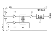
具体的には、「2線差動電圧方式」で伝送されるCANフレームFcの読み取りに際しては、前述の例の中継装置1における電圧検出部11に代えて、図7に示す電圧検出部60を備えて「CANフレーム中継装置」を構成することにより、処理部15によるCANフレームFcの読み取り(内容の特定)を正確かつ容易に行うことが可能となる。この電圧検出部60は、同図に示すように、増幅器61h,61l、差分回路(一例として、トランス)62、増幅器63およびA/D変換器64を備えて構成されている。 Specifically, when reading the CAN frame Fc transmitted by the "2-wire differential voltage method", the voltage detection unit 60 shown in FIG. 7 is used instead of the voltage detection unit 11 in the relay device 1 of the above example. By configuring the "CAN frame relay device", the processing unit 15 can accurately and easily read the CAN frame Fc (specify the contents). As shown in the figure, the voltage detection unit 60 includes amplifiers 61h and 61l, a differential circuit (as an example, a transformer) 62, an amplifier 63, and an A / D converter 64.

前述の電圧検出部11に代えて上記の電圧検出部60を備えた中継装置1によってシリアルバスSB1からCANフレームFcを読み取る際には、「CANH」に対応する信号線、および「CANL」に対応する信号線に非接触式電圧センサ11aをそれぞれ装着する。この状態においてシリアルバスSB1にCANフレームFcが伝送されたときには、「CANH」に対応する信号線のフレーム伝送用導体(以下、「「CANH」の伝送用導体」ともいう)と非接触式電圧センサ11aの検出用電極との間の結合容量を介して、「CANH」の伝送用導体の電位に応じて流れる電流に応じた電圧が増幅器61hによって増幅されると共に、「CANL」に対応する信号線のフレーム伝送用導体(以下、「「CANL」の伝送用導体」ともいう)と非接触式電圧センサ11aの検出用電極との間の結合容量を介して、「CANL」の伝送用導体の電位に応じて流れる電流に応じた電圧が増幅器61lによって増幅される。 When reading the CAN frame Fc from the serial bus SB1 by the relay device 1 provided with the voltage detection unit 60 instead of the voltage detection unit 11, the signal line corresponding to "CANH" and the signal line corresponding to "CANL" are supported. A non-contact voltage sensor 11a is attached to each of the signal lines. When the CAN frame Fc is transmitted to the serial bus SB1 in this state, the frame transmission conductor of the signal line corresponding to "CANH" (hereinafter, also referred to as "the transmission conductor of" CANH ") and the non-contact type voltage sensor". Through the coupling capacitance between the detection electrode and the detection electrode of 11a, the voltage corresponding to the current flowing according to the potential of the transmission conductor of "CANH" is amplified by the amplifier 61h, and the signal line corresponding to "CANL" is amplified. Through the coupling capacitance between the frame transmission conductor (hereinafter, also referred to as “CANL” transmission conductor) and the detection electrode of the non-contact voltage sensor 11a, the potential of the “CANL” transmission conductor. The voltage corresponding to the flowing current is amplified by the amplifier 61l.

また、増幅器61hからの出力電圧と増幅器61lからの出力電圧の差分に対応する電圧が差分回路62から出力され、この出力電圧が増幅器63によって増幅されてA/D変換器64によってA/D変換されて電圧値データとして処理部15に出力される。一方、処理部15は、A/D変換器64から出力された電圧値データの値が予め規定された電圧値レベル以上のときに、デジタル信号の「0」が伝送されていると判別する。また、処理部15は、A/D変換器64から出力された電圧値データの値が予め規定された電圧値レベルを下回っているときに、デジタル信号の「1」が伝送されていると判別する。これにより、前述した電圧検出部11を備えた中継装置1におけるCANフレームFcの読み取り時と同様にして、シリアルバスSB1を伝送されているCANフレームFcの内容が特定される。 Further, a voltage corresponding to the difference between the output voltage from the amplifier 61h and the output voltage from the amplifier 61l is output from the difference circuit 62, and this output voltage is amplified by the amplifier 63 and A / D converted by the A / D converter 64. It is output to the processing unit 15 as voltage value data. On the other hand, the processing unit 15 determines that the digital signal "0" is transmitted when the value of the voltage value data output from the A / D converter 64 is equal to or higher than a predetermined voltage value level. Further, the processing unit 15 determines that the digital signal "1" is transmitted when the value of the voltage value data output from the A / D converter 64 is lower than the predetermined voltage value level. do. Thereby, the content of the CAN frame Fc transmitted through the serial bus SB1 is specified in the same manner as when the CAN frame Fc is read in the relay device 1 provided with the voltage detection unit 11 described above.

また、自動車100の電力ラインLpを流れている電流の「電流値」の測定に際して、電力供給用導体に対して非接触で非接触式電流センサ21aを介して「電流値」を測定する電流測定部21を有する測定装置2を備えたデータ収集システム10の例について説明したが、電力ラインLpの電力供給用導体に対して直接接触して「電流値」を測定する「電流測定部」を備えて「CANフレーム中継装置」を構成することもできる(図示せず)。 Further, when measuring the "current value" of the current flowing through the power line Lp of the automobile 100, the current measurement measures the "current value" via the non-contact type current sensor 21a in a non-contact manner with respect to the power supply conductor. The example of the data acquisition system 10 provided with the measuring device 2 having the unit 21 has been described, but the present invention includes a “current measuring unit” that directly contacts the power supply conductor of the power line Lp and measures the “current value”. It is also possible to configure a "CAN frame relay device" (not shown).

同様にして、自動車100の電力ラインLpに印加されている電圧の「電圧値」の測定に際して、電力供給用導体に対して非接触で非接触式電圧センサ22aを介して「電圧値」を測定する電圧測定部22を有する測定装置2を備えたデータ収集システム10の例について説明したが、電力ラインLpの電力供給用導体に対して直接接触して「電圧値」を測定する「電圧測定部」を備えて「CANフレーム中継装置」を構成することもできる(図示せず)。 Similarly, when measuring the "voltage value" of the voltage applied to the power line Lp of the automobile 100, the "voltage value" is measured via the non-contact type voltage sensor 22a in a non-contact manner with respect to the power supply conductor. Although an example of a data acquisition system 10 including a measuring device 2 having a voltage measuring unit 22 is described, a “voltage measuring unit” that measures a “voltage value” by directly contacting a power supply conductor of a power line Lp has been described. It is also possible to configure a "CAN frame relay device" with "" (not shown).

さらに、電流値データフレームFca2および電圧値データフレームFcv2を測定装置2からシリアルバスSB2を介してデータ処理装置4に伝送し、データ処理装置4において、電流値データフレームFca2および電圧値データフレームFcv2に基づいて「電力値」を演算して電力値データフレームFcp12を生成する構成を例に挙げて説明したが、測定装置2において電流値データDaおよび電圧値データDvに基づいて「電力値」を演算して電力値データフレームFcp12を生成する構成を採用することもできる(図示せず)。 Further, the current value data frame Fca2 and the voltage value data frame Fcv2 are transmitted from the measuring device 2 to the data processing device 4 via the serial bus SB2, and in the data processing device 4, the current value data frame Fca2 and the voltage value data frame Fcv2 are transmitted. The configuration for generating the power value data frame Fpc12 by calculating the "power value" based on the above has been described as an example, but the "power value" is calculated based on the current value data Da and the voltage value data Dv in the measuring device 2. It is also possible to adopt a configuration for generating a power value data frame Fpc12 (not shown).

また、データ収集システム10内で演算された「電力値」を示す電力値データフレームFcp12、および電力値データフレームFcp12に基づいて特定される電力値データDpを記録する記録装置5を備えたデータ収集システム10の例について説明したが、電力値データフレームFcp12や電力値データDpを記録する構成は、「測定システム」に必須の構成要素ではないため、これらを記録しない構成(記録装置5を設けない構成)を採用することもできる(図示せず)。 Further, data collection including a power value data frame Fcp12 indicating the "power value" calculated in the data collection system 10 and a recording device 5 for recording the power value data Dp specified based on the power value data frame Fcp12. An example of the system 10 has been described, but since the configuration for recording the power value data frame Fcp12 and the power value data Dp is not an essential component of the “measurement system”, the configuration for not recording these (the recording device 5 is not provided). Configuration) can also be adopted (not shown).

さらに、電流値データDa、電圧値データDvおよび温度データDtを測定する構成や、電流値データDaおよび電圧値データDvに基づいて電力値データDpを演算する(「電力値」を測定する)構成は、「記録装置」に必須の構成要素ではないため、測定装置2,3やデータ処理装置4を設けずに、シリアルバスSB1から中継装置1を介してシリアルバスSB2に中継された各CANフレームFcや、それらのCANフレームFcに基づいて特定される「電流値」、「電圧値」、「車外温度」および「車内温度」等だけを記録装置5において記録する構成を採用することもできる(図示せず)。 Further, a configuration for measuring current value data Da, voltage value data Dv and temperature data Dt, and a configuration for calculating power value data Dp based on current value data Da and voltage value data Dv (measuring "power value"). Is not an essential component of the "recording device", so each CAN frame relayed from the serial bus SB1 to the serial bus SB2 via the relay device 1 without providing the measuring devices 2 and 3 and the data processing device 4. It is also possible to adopt a configuration in which only the "current value", "voltage value", "outside temperature", "inside temperature", etc. specified based on the Fc and their CAN frame Fc are recorded by the recording device 5 ( Not shown).

また、データ収集システム10の各構成要素1~5については、自動車100などの車両以外の各種の分野(工場内設備用のネットワークや、耕作地内ネットワーク等の分野)において使用することもできる。加えて、「第1のシリアルバス」から「第2のシリアルバス」に中継する「CANフレーム」は、上記の例におけるCANフレームFcに限定されず、「CAN FD」、「FlexRay(登録商標)」および「LIN」などの各種通信規格に準ずるフレーム(デジタルデータ)や、「LVDS」による小振幅低消費電力通信が可能な各種通信規格に準ずるフレーム(デジタルデータ)を異なる「シリアルバス」間で中継することができる。 Further, each component 1 to 5 of the data collection system 10 can be used in various fields other than the vehicle such as the automobile 100 (a field for a network for equipment in a factory, a network in a cultivated land, etc.). In addition, the "CAN frame" relayed from the "first serial bus" to the "second serial bus" is not limited to the CAN frame Fc in the above example, and is "CAN FD" and "FlexRay (registered trademark)". Frames (digital data) conforming to various communication standards such as "" and "LIN", and frames (digital data) conforming to various communication standards capable of small amplitude and low power consumption communication by "LVDS" between different "serial buses". It can be relayed.

10 データ収集システム
1 中継装置
2,3 測定装置
4 データ処理装置
5 記録装置
11 電圧検出部
11a 非接触式電圧センサ
14,35 信号出力部
15,26,36,44,54 処理部
16,27,37,45,55 記憶部
21 電流測定部
21a 非接触式電流センサ
22 電圧測定部
22a 非接触式電圧センサ
25 信号出力部
31,32 温度測定部
31a,32a 温度センサ
41,51 信号入出力部
52 記録媒体
53 データ入出力部
60 電圧検出部
61h,61l 増幅器
62 差分回路
63 増幅器
64 A/D変換器
100 自動車
101a,101b・・ ノード
Da 電流値データ
Dp 電力値データ
Dt 温度データ
Dv 電圧値データ
Fc CANフレーム
Fca1,Fca2 電流値データフレーム
Fcp12 電力値データフレーム
Fct1,Fct2 温度データフレーム
Fcv1,Fcv2 電圧値データフレーム
Lp 電力ライン
SB1,SB2 シリアルバス
10 Data acquisition system 1 Relay device 2, 3 Measuring device 4 Data processing device 5 Recording device 11 Voltage detection unit 11a Non-contact voltage sensor 14, 35 Signal output unit 15, 26, 36, 44, 54 Processing unit 16, 27, 37,45,55 Storage unit 21 Current measurement unit 21a Non-contact current sensor 22 Voltage measurement unit 22a Non-contact type voltage sensor 25 Signal output unit 31, 32 Temperature measurement unit 31a, 32a Temperature sensor 41,51 Signal input / output unit 52 Recording medium 53 Data input / output unit 60 Voltage detection unit 61h, 61l Amplifier 62 Difference circuit 63 Amplifier 64 A / D converter 100 Automobile 101a, 101b ... Node Da Current value data Dp Power value data Dt Temperature data Dv Voltage value data Fc CAN frame Fca1, Fca2 current value data frame Fcp12 power value data frame Fct1, Fct2 temperature data frame Fcv1, Fcv2 voltage value data frame Lp power line SB1, SB2 serial bus

Claims (8)

CAN通信用の第1のシリアルバスを介して伝送されるCANフレームを当該第1のシリアルバスから読み取るCANフレーム読取部と、
前記CANフレーム読取部によって読み取られた前記CANフレームを前記第1のシリアルバスとは異なるCAN通信用の第2のシリアルバスに出力するCANフレーム出力部とを備え、
前記CANフレーム読取部は、前記CANフレームの伝送時に前記第1のシリアルバスにおけるフレーム伝送用導体に印加される電圧を当該フレーム伝送用導体に対して非接触で検出可能な非接触式電圧センサを有する電圧検出部と、当該電圧検出部によって検出された前記電圧の電圧レベルの変化に基づいて前記第1のシリアルバスを介して伝送された前記CANフレームを特定するフレーム特定部とを備えているCANフレーム中継装置。
A CAN frame reader that reads a CAN frame transmitted via a first serial bus for CAN communication from the first serial bus, and a CAN frame reader.
It is provided with a CAN frame output unit that outputs the CAN frame read by the CAN frame reading unit to a second serial bus for CAN communication different from the first serial bus.
The CAN frame reader is a non-contact voltage sensor capable of detecting the voltage applied to the frame transmission conductor in the first serial bus in a non-contact manner with respect to the frame transmission conductor during transmission of the CAN frame. It includes a voltage detecting unit having a voltage detecting unit, and a frame specifying unit that identifies the CAN frame transmitted via the first serial bus based on a change in the voltage level of the voltage detected by the voltage detecting unit. CAN frame relay device.
前記CANフレーム読取部によって前記第1のシリアルバスから読み取られた前記CANフレームのフレームIDを予め規定された変更規則に従って変更し、変更後の当該CANフレームを前記CANフレーム出力部から前記第2のシリアルバスに出力させるID変更処理部を備えている請求項1記載のCANフレーム中継装置。 The frame ID of the CAN frame read from the first serial bus by the CAN frame reading unit is changed according to a predetermined change rule, and the changed CAN frame is changed from the CAN frame output unit to the second unit. The CAN frame relay device according to claim 1, further comprising an ID change processing unit for outputting to a serial bus. 前記CANフレーム読取部によって前記第1のシリアルバスから読み取られた前記CANフレームのうちの予め規定された条件を満たす当該CANフレームを前記CANフレーム出力部から前記第2のシリアルバスに出力させるフィルタリング処理部を備えている請求項1または2記載のCANフレーム中継装置。 Filtering process to output the CAN frame that satisfies the predetermined condition among the CAN frames read from the first serial bus by the CAN frame reading unit from the CAN frame output unit to the second serial bus. The CAN frame relay device according to claim 1 or 2, further comprising a unit. 請求項1から3のいずれかに記載のCANフレーム中継装置と、
前記第2のシリアルバスに接続されると共に、前記CANフレーム読取部によって前記第1のシリアルバスから読み取られて前記CANフレーム出力部によって前記第2のシリアルバスに出力された前記CANフレームに基づいて予め規定された被測定量を測定可能に構成された測定装置とを備えている測定システム。
The CAN frame relay device according to any one of claims 1 to 3 and the CAN frame relay device.
Based on the CAN frame connected to the second serial bus, read from the first serial bus by the CAN frame reader, and output to the second serial bus by the CAN frame output unit. A measurement system equipped with a measuring device configured to be able to measure a predetermined measured amount.
請求項1から3のいずれかに記載のCANフレーム中継装置と、
前記第2のシリアルバスに接続されると共に、前記CANフレーム読取部によって前記第1のシリアルバスから読み取られて前記CANフレーム出力部によって前記第2のシリアルバスに出力された前記CANフレーム、および当該CANフレームに基づいて予め規定された演算処理によって演算した演算結果の少なくとも一方を記録可能に構成された記録装置とを備えている記録システム。
The CAN frame relay device according to any one of claims 1 to 3 and the CAN frame relay device.
The CAN frame connected to the second serial bus, read from the first serial bus by the CAN frame reader, and output to the second serial bus by the CAN frame output unit, and the CAN frame. A recording system including a recording device configured to be able to record at least one of the calculation results calculated by a predetermined calculation process based on a CAN frame.
CAN通信用の第1のシリアルバスを介して伝送されるCANフレームを当該第1のシリアルバスから読み取ると共に、読み取った前記CANフレームを前記第1のシリアルバスとは異なるCAN通信用の第2のシリアルバスに出力する際に、
前記CANフレームの伝送時に前記第1のシリアルバスにおけるフレーム伝送用導体に印加される電圧を当該フレーム伝送用導体に対して非接触で検出し、検出した前記電圧の電圧レベルの変化に基づいて前記第1のシリアルバスを介して伝送された前記CANフレームを特定するCANフレーム中継方法。
A CAN frame transmitted via the first serial bus for CAN communication is read from the first serial bus, and the read CAN frame is used for a second CAN communication different from the first serial bus. When outputting to the serial bus
The voltage applied to the frame transmission conductor in the first serial bus during transmission of the CAN frame is detected in a non-contact manner with respect to the frame transmission conductor, and the voltage level of the detected voltage is changed. A CAN frame relay method for specifying the CAN frame transmitted via the first serial bus.
前記第1のシリアルバスから読み取った前記CANフレームのフレームIDを予め規定された変更規則に従って変更し、変更後の当該CANフレームを前記第2のシリアルバスに出力する請求項6記載のCANフレーム中継方法。 The CAN frame relay according to claim 6, wherein the frame ID of the CAN frame read from the first serial bus is changed according to a predetermined change rule, and the changed CAN frame is output to the second serial bus. Method. 前記第1のシリアルバスから読み取った前記CANフレームのうちの予め規定された条件を満たす当該CANフレームを前記第2のシリアルバスに出力するフィルタリング処理を実行する請求項6または7記載のCANフレーム中継方法。 The CAN frame relay according to claim 6 or 7, which executes a filtering process for outputting the CAN frame that satisfies the predetermined condition among the CAN frames read from the first serial bus to the second serial bus. Method.
JP2018039508A 2018-03-06 2018-03-06 CAN frame relay device, measurement system, recording system and CAN frame relay method Active JP6991895B2 (en)

Priority Applications (1)

Application Number Priority Date Filing Date Title
JP2018039508A JP6991895B2 (en) 2018-03-06 2018-03-06 CAN frame relay device, measurement system, recording system and CAN frame relay method

Applications Claiming Priority (1)

Application Number Priority Date Filing Date Title
JP2018039508A JP6991895B2 (en) 2018-03-06 2018-03-06 CAN frame relay device, measurement system, recording system and CAN frame relay method

Publications (2)

Publication Number Publication Date
JP2019153995A JP2019153995A (en) 2019-09-12
JP6991895B2 true JP6991895B2 (en) 2022-01-13

Family

ID=67947175

Family Applications (1)

Application Number Title Priority Date Filing Date
JP2018039508A Active JP6991895B2 (en) 2018-03-06 2018-03-06 CAN frame relay device, measurement system, recording system and CAN frame relay method

Country Status (1)

Country Link
JP (1) JP6991895B2 (en)

Families Citing this family (1)

* Cited by examiner, † Cited by third party
Publication number Priority date Publication date Assignee Title
JP7577610B2 (en) * 2021-06-15 2024-11-05 日置電機株式会社 Measuring Equipment

Citations (5)

* Cited by examiner, † Cited by third party
Publication number Priority date Publication date Assignee Title
JP2003204371A (en) 2001-08-29 2003-07-18 Sensor Technologies Inc Analyzer sensor
JP2003244779A (en) 2002-02-18 2003-08-29 Takasaki Kyodo Keisan Center:Kk CAN communication diagnostic device
CN101943901A (en) 2010-08-11 2011-01-12 西安电子科技大学 Online data monitoring device of non-contact-type 485 bus
JP2014225768A (en) 2013-05-16 2014-12-04 学校法人慶應義塾 Coated electric wire coupling information communication network, electromagnetic field coupling communication method, and electromagnetic field coupler
JP2016223866A (en) 2015-05-29 2016-12-28 日置電機株式会社 Voltage detecting probe, and measuring device

Patent Citations (5)

* Cited by examiner, † Cited by third party
Publication number Priority date Publication date Assignee Title
JP2003204371A (en) 2001-08-29 2003-07-18 Sensor Technologies Inc Analyzer sensor
JP2003244779A (en) 2002-02-18 2003-08-29 Takasaki Kyodo Keisan Center:Kk CAN communication diagnostic device
CN101943901A (en) 2010-08-11 2011-01-12 西安电子科技大学 Online data monitoring device of non-contact-type 485 bus
JP2014225768A (en) 2013-05-16 2014-12-04 学校法人慶應義塾 Coated electric wire coupling information communication network, electromagnetic field coupling communication method, and electromagnetic field coupler
JP2016223866A (en) 2015-05-29 2016-12-28 日置電機株式会社 Voltage detecting probe, and measuring device

Also Published As

Publication number Publication date
JP2019153995A (en) 2019-09-12

Similar Documents

Publication Publication Date Title
US9087420B2 (en) System and method for identifying, diagnosing, maintaining, and repairing a vehicle
US8340855B2 (en) USB isolation for vehicle communication interface
US9317977B2 (en) Mobile communication interface, system having a mobile communication interface, and method for identifying, diagnosing, maintaining, and repairing a vehicle
US9665993B2 (en) Mobile communication interface, system having a mobile communication interface, and method for identifying, diagnosing, maintaining, and repairing a vehicle
US9479220B2 (en) Methods and systems for detection and analysis of abnormalities in a power line communication network of a vehicle
EP4033318B1 (en) Automobile diagnosis device, system and method
US10626877B2 (en) Method and system for controlling cooling fan in vehicle
CN102150057A (en) Monitoring system for an accumulator
CN105745551B (en) Device and method for testing motor vehicle batteries
US20180370459A1 (en) Apparatus and method for checking or monitoring in-vehicle control unit
JP2021043026A (en) Signal generation device and signal reading system
JP6991895B2 (en) CAN frame relay device, measurement system, recording system and CAN frame relay method
CN111907445B (en) A CAN bus layout structure based on electric light truck
CN207851175U (en) An EMC Free Field Immunity Test Network Communication Monitoring System
CN104160427B (en) Current measuring device and method
CN110896158A (en) Battery management system, battery management unit and unit to be managed
CN118844047A (en) Device with communication means for data transmission via a data transmission bus and data transmission system with such a device
KR20170039950A (en) Apparatus and method for inspecting vehicle
JP2020167491A (en) Data transmission system
JP7279009B2 (en) Power calculation device and power calculation method
JP5175641B2 (en) Communication system disconnection detection apparatus and communication system
JP6265767B2 (en) Communication diagnostic device, communication diagnostic system, communication diagnostic method, and program
JP2019144246A (en) Electric power computing device and electric power computing method
JP7027232B2 (en) Waveform data generator, power calculation system, waveform data generation method and power calculation method
JP2010136521A (en) Information communication system with electric vehicle and vehicle-body diagnosis system

Legal Events

Date Code Title Description
A621 Written request for application examination

Free format text: JAPANESE INTERMEDIATE CODE: A621

Effective date: 20210125

A977 Report on retrieval

Free format text: JAPANESE INTERMEDIATE CODE: A971007

Effective date: 20211028

TRDD Decision of grant or rejection written
A01 Written decision to grant a patent or to grant a registration (utility model)

Free format text: JAPANESE INTERMEDIATE CODE: A01

Effective date: 20211124

A61 First payment of annual fees (during grant procedure)

Free format text: JAPANESE INTERMEDIATE CODE: A61

Effective date: 20211208

R150 Certificate of patent or registration of utility model

Ref document number: 6991895

Country of ref document: JP

Free format text: JAPANESE INTERMEDIATE CODE: R150

R250 Receipt of annual fees

Free format text: JAPANESE INTERMEDIATE CODE: R250

R250 Receipt of annual fees

Free format text: JAPANESE INTERMEDIATE CODE: R250