JP6991879B2 - Printer - Google Patents
Printer Download PDFInfo
- Publication number
- JP6991879B2 JP6991879B2 JP2018023093A JP2018023093A JP6991879B2 JP 6991879 B2 JP6991879 B2 JP 6991879B2 JP 2018023093 A JP2018023093 A JP 2018023093A JP 2018023093 A JP2018023093 A JP 2018023093A JP 6991879 B2 JP6991879 B2 JP 6991879B2
- Authority
- JP
- Japan
- Prior art keywords
- cover
- paper
- printer
- opening
- main body
- Prior art date
- Legal status (The legal status is an assumption and is not a legal conclusion. Google has not performed a legal analysis and makes no representation as to the accuracy of the status listed.)
- Active
Links
Images

Classifications
-
- B—PERFORMING OPERATIONS; TRANSPORTING
- B41—PRINTING; LINING MACHINES; TYPEWRITERS; STAMPS
- B41J—TYPEWRITERS; SELECTIVE PRINTING MECHANISMS, i.e. MECHANISMS PRINTING OTHERWISE THAN FROM A FORME; CORRECTION OF TYPOGRAPHICAL ERRORS
- B41J2/00—Typewriters or selective printing mechanisms characterised by the printing or marking process for which they are designed
- B41J2/315—Typewriters or selective printing mechanisms characterised by the printing or marking process for which they are designed characterised by selective application of heat to a heat sensitive printing or impression-transfer material
- B41J2/32—Typewriters or selective printing mechanisms characterised by the printing or marking process for which they are designed characterised by selective application of heat to a heat sensitive printing or impression-transfer material using thermal heads
-
- B—PERFORMING OPERATIONS; TRANSPORTING
- B41—PRINTING; LINING MACHINES; TYPEWRITERS; STAMPS
- B41J—TYPEWRITERS; SELECTIVE PRINTING MECHANISMS, i.e. MECHANISMS PRINTING OTHERWISE THAN FROM A FORME; CORRECTION OF TYPOGRAPHICAL ERRORS
- B41J11/00—Devices or arrangements of selective printing mechanisms, e.g. ink-jet printers or thermal printers, for supporting or handling copy material in sheet or web form
- B41J11/02—Platens
- B41J11/04—Roller platens
-
- B—PERFORMING OPERATIONS; TRANSPORTING
- B41—PRINTING; LINING MACHINES; TYPEWRITERS; STAMPS
- B41J—TYPEWRITERS; SELECTIVE PRINTING MECHANISMS, i.e. MECHANISMS PRINTING OTHERWISE THAN FROM A FORME; CORRECTION OF TYPOGRAPHICAL ERRORS
- B41J13/00—Devices or arrangements of selective printing mechanisms, e.g. ink-jet printers or thermal printers, specially adapted for supporting or handling copy material in short lengths, e.g. sheets
- B41J13/10—Sheet holders, retainers, movable guides, or stationary guides
- B41J13/106—Sheet holders, retainers, movable guides, or stationary guides for the sheet output section
-
- B—PERFORMING OPERATIONS; TRANSPORTING
- B41—PRINTING; LINING MACHINES; TYPEWRITERS; STAMPS
- B41J—TYPEWRITERS; SELECTIVE PRINTING MECHANISMS, i.e. MECHANISMS PRINTING OTHERWISE THAN FROM A FORME; CORRECTION OF TYPOGRAPHICAL ERRORS
- B41J15/00—Devices or arrangements of selective printing mechanisms, e.g. ink-jet printers or thermal printers, specially adapted for supporting or handling copy material in continuous form, e.g. webs
- B41J15/04—Supporting, feeding, or guiding devices; Mountings for web rolls or spindles
- B41J15/042—Supporting, feeding, or guiding devices; Mountings for web rolls or spindles for loading rolled-up continuous copy material into printers, e.g. for replacing a used-up paper roll; Point-of-sale printers with openable casings allowing access to the rolled-up continuous copy material
-
- B—PERFORMING OPERATIONS; TRANSPORTING
- B41—PRINTING; LINING MACHINES; TYPEWRITERS; STAMPS
- B41J—TYPEWRITERS; SELECTIVE PRINTING MECHANISMS, i.e. MECHANISMS PRINTING OTHERWISE THAN FROM A FORME; CORRECTION OF TYPOGRAPHICAL ERRORS
- B41J3/00—Typewriters or selective printing or marking mechanisms characterised by the purpose for which they are constructed
- B41J3/407—Typewriters or selective printing or marking mechanisms characterised by the purpose for which they are constructed for marking on special material
- B41J3/4075—Tape printers; Label printers
-
- B—PERFORMING OPERATIONS; TRANSPORTING
- B65—CONVEYING; PACKING; STORING; HANDLING THIN OR FILAMENTARY MATERIAL
- B65H—HANDLING THIN OR FILAMENTARY MATERIAL, e.g. SHEETS, WEBS, CABLES
- B65H19/00—Changing the web roll
- B65H19/22—Changing the web roll in winding mechanisms or in connection with winding operations
- B65H19/30—Lifting, transporting, or removing the web roll; Inserting core
-
- B—PERFORMING OPERATIONS; TRANSPORTING
- B41—PRINTING; LINING MACHINES; TYPEWRITERS; STAMPS
- B41J—TYPEWRITERS; SELECTIVE PRINTING MECHANISMS, i.e. MECHANISMS PRINTING OTHERWISE THAN FROM A FORME; CORRECTION OF TYPOGRAPHICAL ERRORS
- B41J3/00—Typewriters or selective printing or marking mechanisms characterised by the purpose for which they are constructed
- B41J3/36—Typewriters or selective printing or marking mechanisms characterised by the purpose for which they are constructed for portability, i.e. hand-held printers or laptop printers
Landscapes
- Accessory Devices And Overall Control Thereof (AREA)
- Printers Characterized By Their Purpose (AREA)
- Electronic Switches (AREA)
Description
本発明の実施形態は、プリンタに関する。 Embodiments of the present invention relate to printers.
プリンタの一種に、店舗のバックヤードで用いられるラベルプリンタがある。プリンタは、用紙補充やメンテナンスに際し、筐体を開閉する必要があるが、雑多なバックヤードにおいては、プリンタの周囲に、筐体を開閉するためのスペースを確保するのが困難なことがある。 One type of printer is a label printer used in the backyard of a store. The printer needs to open and close the housing for paper replenishment and maintenance, but in a miscellaneous backyard, it may be difficult to secure a space for opening and closing the housing around the printer.
例えば、筐体の上面に開閉蓋があるプリンタならば、筐体の上方に、蓋の開け閉めのための空間を確保しなければならないし、また例えば、筐体の前面に開閉蓋があるプリンタならば、筐体の前方に、蓋の開け閉めのための空間を確保しなければならない。 For example, in the case of a printer having an opening / closing lid on the upper surface of the housing, a space for opening / closing the lid must be secured above the housing, and for example, a printer having an opening / closing lid on the front surface of the housing. If so, a space for opening and closing the lid must be secured in front of the housing.
このように、プリンタは、設置場所によってアクセス可能な方向が制約されることがある。このような問題は、バックヤードで用いられるラベルプリンタでなくとも、同様に起こり得る。 As described above, the accessible direction of the printer may be restricted depending on the installation location. Such problems can occur as well, even if the label printer is not used in the backyard.
本発明が解決しようとする課題は、設置の自由度が高いプリンタを提供することである。 An object to be solved by the present invention is to provide a printer having a high degree of freedom in installation.
実施形態のプリンタは、本体部、第一カバー、第二カバー、印字部、共通位置決め部、第一カバーに設けられたレバーおよび第二カバーに設けられたレバーを、備える。本体部は、用紙を収納する用紙収納部を内蔵し、隣り合う2面に、それぞれ前記用紙収納部への用紙補充を可能にする開口部を有する。第一カバーは、前記開口部のうちの一方である第一開口部を開閉する。第二カバーは、前記開口部のうちの他方である第二開口部を開閉する。印字部は、前記第一カバーに設けられた印字ヘッドと、前記第二カバーに設けられて前記印字ヘッドとの間に挟んだ用紙を搬送するプラテンローラとを備え、前記用紙収納部から引き出された用紙に印字し、前記第一カバーおよび前記第二カバーの互いに隣り合う端部の間から用紙を排出する。共通位置決め部は、前記第一開口部を閉じる位置に前記第一カバーを位置決めするとともに前記第二開口部を閉じる位置に前記第二カバーを位置決めするための、前記本体部に設けられている。前記第一カバーに設けられたレバーは、前記第一カバーが前記第一開口部を閉じる位置にあるときに前記共通位置決め部に引っかかる。前記第二カバーに設けられたレバーは、前記第二カバーが前記第二開口部を閉じる位置にあるときに前記共通位置決め部に引っかかる。 The printer of the embodiment includes a main body unit, a first cover , a second cover , a printing unit, a common positioning unit, a lever provided on the first cover, and a lever provided on the second cover . The main body has a built-in paper storage unit for storing paper, and has openings on two adjacent sides, each of which allows paper to be replenished to the paper storage unit. The first cover opens and closes one of the first openings . The second cover opens and closes the second opening, which is the other of the openings . The printing unit includes a printing head provided on the first cover and a platen roller provided on the second cover and transporting paper sandwiched between the printing heads, and is drawn out from the paper storage unit. The paper is printed on the paper, and the paper is ejected from between the adjacent ends of the first cover and the second cover. The common positioning portion is provided on the main body portion for positioning the first cover at a position where the first opening is closed and positioning the second cover at a position where the second opening is closed. The lever provided on the first cover is caught on the common positioning portion when the first cover is in a position to close the first opening. The lever provided on the second cover is caught on the common positioning portion when the second cover is in the position of closing the second opening .
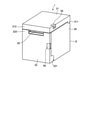
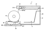
実施形態について図面を用いて説明する。図1は、実施形態のプリンタ1の外観を示す斜視図である。プリンタ1は、筐体2を有する。筐体2の形状は、箱型(例えば略直方体もしくは略立方体)である。筐体2は、筐体2の主部を構成する本体部20と、筐体2の一部を構成する第一カバー21および第二カバー22と、を備えている。
The embodiment will be described with reference to the drawings. FIG. 1 is a perspective view showing the appearance of the
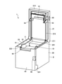
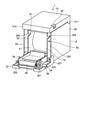
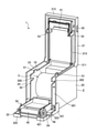
図2は、第一カバー21を開放した状態のプリンタ1の斜視図である。図3は、第二カバー22を開放した状態のプリンタ1の斜視図である。図4は、第一カバー21および第二カバー22を開放したプリンタ1の斜視図である。本体部20は、筐体2の異なる2面に、開口部23,24を有している。第一カバー21は、一方の開口部23を開閉する。第二カバー22は、他方の開口部24を開閉する。
FIG. 2 is a perspective view of the
図5は、第一カバー21および第二カバー22を閉じたプリンタ1の縦断側面図である。図6は、図3に対応し、第二カバー22を開放した状態のプリンタ1の縦断側面図である。プリンタ1は、さらに、用紙収納部3および印字部4を備えている。
FIG. 5 is a vertical sectional side view of the
用紙収納部3は、本体部20内に設けられており、ロール紙10を収納し、回転自在に保持する。ロール紙10は、用紙を巻いたものであって、例えばラベルロールやレシートロールである。ラベルロールは、ラベルが所定間隔で貼付された帯状の台紙が巻かれたものである。レシートロールは、帯状の紙が巻かれたものである。開口部23,24は、それぞれが、用紙収納部3への用紙の補充や交換を、可能にする。
The
ここで、用紙収納部3は、ロール紙10を、いわゆる投げ込み式で保持するのであってもよいし、或いは、ロール紙10の中空部に差し込まれて回転の軸となる芯材を、所定の保持部で保持するのであってもよい。
Here, the
印字部4は、用紙収納部3から引き出された用紙に印字する。印字部4は、印字ヘッド41とプラテンローラ42とを備えている。
The
本実施形態では、開口部23,24は、筐体2の隣り合う2面に設けられており、第一カバー21と第二カバー22との間に、用紙を排出する排紙口25(図1および図5参照)が設けられている。
In the present embodiment, the
また、本実施形態では、第一カバー21は、本体部20に、一端部211を回動可能に取り付けられていて、回動に伴って開口部23を開閉する。この第一カバー21の他端部212は、排紙口25に面している。さらに、第二カバー22は、本体部20に、一端部221を回動可能に取り付けられていて、回動に伴って開口部24を開閉する。この第二カバー22の他端部222は、排紙口25に面している。
Further, in the present embodiment, the
印字ヘッド41は、第一カバー21に取り付けられていて、プラテンローラ42は、第二カバー22に取り付けられている。第一カバー21が開口部23を閉じ、且つ、第二カバー22が開口部24を閉じているとき、印字ヘッド41にプラテンローラ42が接して、プリンタ1が印字可能な状態になる。
The
印字ヘッド41は、例えばサーマルヘッドである。プラテンローラ42は、ステッピングモータなどの駆動力を、ギヤ421(図4等参照)を介して伝達されることにより、回転する。プラテンローラ42が回転すると、印字ヘッド41との間に挟まれた用紙が搬送される。
The
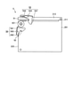
図7は、ロック部5の外観を示すプリンタ1内部の側面図である。なお、図7に示したのは、プリンタ1から筐体2の外装部分を取り除いたものである。以下、本体部20の外装を除いたもの(フレーム部分)を本体フレーム201、第一カバー21から外装を除いたものを第一フレーム213、第二カバー22から外装を除いたものを第二フレーム223、とする。本体フレーム201には、ギヤ421とプラテンローラ42との回転軸を避ける切欠き202(図4等参照)が設けられている。第二カバー22が筐体2を閉じる位置に位置するとき、ギヤ421とプラテンローラ42との間に本体フレーム201の切欠き202周りの部分が位置し、ギヤ421の回転軸が切欠き202に入り込む。
FIG. 7 is a side view of the inside of the
プリンタ1は、ロック部5を、さらに備えている。ロック部5は、ピン51,52と、レバー53,54と、ボタン55,56(図1参照)と、を備えている。
The
レバー53,54は、鉤状の形状のロック端531,541と、オペレータからの力が伝達される操作端532,542と、回動中心533,543と、を有している。レバー53は、回動中心533において、第一カバー21に軸支されている。レバー54は、回動中心543において、第二カバー22に軸支されている。
The
ロック端531は、第一フレーム213の排紙口25寄りの端部を幅方向に挟む一対の位置に、設けられている。また、ロック端541は、第二フレーム223の排紙口25寄りの端部を幅方向に挟む一対の位置に、設けられている。
The
操作端532は、図7に示す側面視において、回動中心533を挟んでロック端531の反対側に位置し、一対のロック端531をつなぐ部分に設けられている。また、操作端542は、図7に示す側面視において、回動中心543を挟んでロック端541の反対側に位置し、一対のロック端541をつなぐ部分に設けられている。
The
ピン51は、本体フレーム201に設けられていて、第一カバー21を閉じたときにレバー53が引っかかるものである。ピン52は、本体フレーム201に設けられていて、第二カバー22を閉じたときにレバー54が引っかかるものである。
The
ボタン55は、第一カバー21に設けられていて、レバー53の操作端532の近傍に位置し、オペレータから受けた力を操作端532に伝達してレバー53を回動させる。
The
このような構成において、プリンタ1は、用紙収納部3に収納・保持されたロール紙10を、プラテンローラ42を回転させて引き出し、引き出された用紙に印字ヘッド41で印字し、用紙を排紙口25から排出する。
In such a configuration, the
また、このような構成のプリンタ1に対して、オペレータは、用紙収納部3に対する用紙の補充・交換を、第一カバー21または第二カバー22を開放することにより行う。また、オペレータは、用紙収納部3に入れ込んだロール紙10から引き出した用紙の先端部を筐体2外に保持した状態で、開放されている第一カバー21または第二カバー22を閉じる。これにより、用紙が印字ヘッド41とプラテンローラ42とに挟まれ、用紙の先端部が排紙口25から筐体2外に出た状態になる。
Further, for the
このようなプリンタ1を用いるオペレータは、用紙の補充・交換、或いはプリンタ1のメンテナンスなど、筐体2を開放する必要がある場合に、第一カバー21および第二カバー22のどちらを開放するのかを、選択することができる。よって、オペレータは、プリンタ1を設置する環境を整えるにあたり、第一カバー21か第二カバー22のどちらかが開放可能な状態を保てればよい。つまり、本実施形態により、設置の自由度が高いプリンタ1を提供することができる。
Which of the
このように、プリンタ1は、筐体2の異なる2面に用紙補充を可能にする開口部23,24を有し、各開口部23,24を第一カバー21,第二カバー22で開閉するようにしたので、プリンタ1の設置環境に応じて、第一カバー21,第二カバー22のうち開放可能な方を使用することができる。
In this way, the
また、プリンタ1は、筐体2の隣り合う2面に開口部23,24を有しているので、第一カバー21,第二カバー22の両方を開放することにより、装置内部を大きく開放することができるため、メンテナンス等に際して好適である。
Further, since the
また、プリンタ1においては、印字ヘッド41が第一カバー21に、プラテンローラ42が第二カバー22に、取り付けられている。これにより、第一カバー21,第二カバー22のどちらが開放された場合であっても、印字ヘッド41とプラテンローラ42とを離間させることができ、筐体2を閉じることによって、用紙を印字ヘッド41とプラテンローラ42との間に容易に挟むことができる。
Further, in the
また、本実施形態では、第一カバー21および第二カバー22は、本体部20に回動可能に取り付けられ、回動に伴って筐体2を開閉する構造とされている。実施にあたっては、第一カバー21および第二カバー22を、例えば本体部20に対してスライド可能に設けて、スライドに伴って筐体2を開閉する構造とすることも可能である。しかしながら、後者の構造に比べ、前者の方が、開閉のための構造の実現に要するコストを低く抑えやすい。
Further, in the present embodiment, the
なお、本実施形態では、用紙としてロール紙10を用いるプリンタ1を例に説明したが、実施にあたっては、別の形態の用紙に印字するプリンタに、筐体の異なる2面を開閉する構造を適用しても構わない。また、本実施形態では、図1等において、排紙口25を正面に向けてプリンタ1を図示したが、実施にあたっては、排紙口25が例えば上向きなど他の向きを向く状態でプリンタ1が使用されてもよい。
In the present embodiment, the
また、本実施形態の開口部23,24は、各々、筐体2の一面の全体を構成するが、実施にあたっては、筐体2の一面の全体でなく一部を構成するのであってもよい。
Further, although the
また、本実施形態のレバー53,54は、回動することによりロックおよびロック解除をするものであるが、実施にあたって、レバー53,54の動作は回動以外であってもよい。
Further, although the
(変形例)
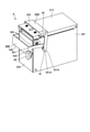
以下、ロック部の変形例について説明する。図8は、ロック部の他の例(ロック部6)の外観を示すプリンタ1内部の斜視図である。ロック部6の説明にあたっては、ロック部5の各部と同じである部分については同じ符号を用い、対応するが異なる部分については、末尾に「A」を付けた符号を用いる。
(Modification example)
Hereinafter, a modified example of the lock portion will be described. FIG. 8 is a perspective view of the inside of the
ロック部6は、ロック部5のピン51とピン52とを共通化して1本にしたピン61と、ピン61に合わせてレバー53を変形させたレバー53Aと、ピン61に合わせてレバー54を変形させたレバー54Aと、を備えている。ピン61は、共通位置決め部の一例であって、第一カバー21を位置決めするとともに、第二カバー22を位置決めする。
The
レバー53A,54Aのロック端531A,541Aは、図7に示すロック端531,541よりも長く、先端部が回動中心533,543から離れている。ピン61は、ロック端531A,541Aが交わる位置に設けられている。
The lock ends 531A and 541A of the
このように、ピン61を共通化することによって、プリンタ1における印字精度を得やすくすることができる。というのも、印字部4における印字ヘッド41とプラテンローラ42との位置精度が、印字精度に重要であるためである。プリンタ1において、印字ヘッド41とプラテンローラ42との位置精度を好適にするには、本体部20に対する第一カバー21の位置精度を良くするとともに、本体部20に対する第二カバー22の位置精度をも良くしなければならない。
By sharing the
ロック部5のように、第一カバー21を固定するためのピン51と第二カバー22を固定するためのピン52とが別々に本体部20に設けられていると、ピン51とピン52とのそれぞれの位置の誤差を合計した誤差が、印字部4に影響することとなる。
When the
これに対して、ロック部6のように、本体部20に設けられた一つのピン61に、第一カバー21も第二カバー22も固定するのであれば、位置の誤差の原因が一つになるので、誤差の管理が比較的容易になる。
On the other hand, if both the
本発明のいくつかの実施形態を説明したが、これらの実施形態は、例として提示したものであり、発明の範囲を限定することは意図していない。これら新規な実施形態は、その他の様々な形態で実施されることが可能であり、発明の要旨を逸脱しない範囲で、種々の省略、置き換え、変更を行うことができる。これら実施形態やその変形は、発明の範囲や要旨に含まれるとともに、特許請求の範囲に記載された発明とその均等の範囲に含まれる。 Although some embodiments of the present invention have been described, these embodiments are presented as examples and are not intended to limit the scope of the invention. These novel embodiments can be implemented in various other embodiments, and various omissions, replacements, and changes can be made without departing from the gist of the invention. These embodiments and variations thereof are included in the scope and gist of the invention, and are also included in the scope of the invention described in the claims and the equivalent scope thereof.
1 …プリンタ
10…ロール紙
2 …筐体
20…本体部、201…本体フレーム
21…第一カバー、211…一端部、212…他端部、213…第一フレーム
22…第二カバー、221…一端部、222…他端部、223…第二フレーム
23,24…開口部
25…排紙口
3 …用紙収納部
4 …印字部
41…印字ヘッド
42…プラテンローラ、421…ギヤ
5…ロック部
51,52…ピン
53…レバー、531…ロック端、532…操作端、533…回動中心
54…レバー、541…ロック端、542…操作端、543…回動中心
55,56…ボタン
6…ロック部、61…ピン
53A,54A…レバー
531A,541A…ロック端
1 ...
Claims (3)
前記開口部のうちの一方である第一開口部を開閉する第一カバーと、
前記開口部のうちの他方である第二開口部を開閉する第二カバーと、
前記第一カバーに設けられた印字ヘッドと、前記第二カバーに設けられて前記印字ヘッドとの間に挟んだ用紙を搬送するプラテンローラとを備え、前記用紙収納部から引き出された用紙に印字し、前記第一カバーおよび前記第二カバーの互いに隣り合う端部の間から用紙を排出する印字部と、
前記第一開口部を閉じる位置に前記第一カバーを位置決めするとともに前記第二開口部を閉じる位置に前記第二カバーを位置決めするための、前記本体部に設けられた共通位置決め部と、
前記第一カバーが前記第一開口部を閉じる位置にあるときに前記共通位置決め部に引っかかる、前記第一カバーに設けられたレバーと、
前記第二カバーが前記第二開口部を閉じる位置にあるときに前記共通位置決め部に引っかかる、前記第二カバーに設けられたレバーと、
を備えるプリンタ。 A main body unit that has a built-in paper storage unit for storing paper and has openings on two adjacent sides that allow paper to be replenished to the paper storage unit.
A first cover that opens and closes the first opening, which is one of the openings ,
A second cover that opens and closes the second opening, which is the other of the openings ,
A print head provided on the first cover and a platen roller provided on the second cover to convey the paper sandwiched between the print heads are provided, and printing is performed on the paper drawn from the paper storage unit. Then, a printing unit that ejects paper from between the first cover and the adjacent ends of the second cover, and a printing unit.
A common positioning unit provided on the main body for positioning the first cover at a position where the first opening is closed and positioning the second cover at a position where the second opening is closed.
A lever provided on the first cover that is caught on the common positioning portion when the first cover is in a position to close the first opening.
A lever provided on the second cover that is caught on the common positioning portion when the second cover is in a position to close the second opening.
A printer equipped with.
請求項1に記載のプリンタ。 The printer according to claim 1 , wherein the common positioning portion is provided on a surface of the main body portion adjacent to both the first opening portion and the second opening portion .
請求項1または2に記載のプリンタ。 The printer according to claim 1 or 2, wherein the first cover and the second cover are rotatably attached to the main body at ends separated from each other .
Priority Applications (4)
| Application Number | Priority Date | Filing Date | Title |
|---|---|---|---|
| JP2018023093A JP6991879B2 (en) | 2018-02-13 | 2018-02-13 | Printer |
| US16/254,294 US10773527B2 (en) | 2018-02-13 | 2019-01-22 | Printer |
| CN201920154913.7U CN209971900U (en) | 2018-02-13 | 2019-01-29 | Printer with a movable platen |
| EP19156641.3A EP3524437B1 (en) | 2018-02-13 | 2019-02-12 | Printer |
Applications Claiming Priority (1)
| Application Number | Priority Date | Filing Date | Title |
|---|---|---|---|
| JP2018023093A JP6991879B2 (en) | 2018-02-13 | 2018-02-13 | Printer |
Publications (2)
| Publication Number | Publication Date |
|---|---|
| JP2019136962A JP2019136962A (en) | 2019-08-22 |
| JP6991879B2 true JP6991879B2 (en) | 2022-01-13 |
Family
ID=65411806
Family Applications (1)
| Application Number | Title | Priority Date | Filing Date |
|---|---|---|---|
| JP2018023093A Active JP6991879B2 (en) | 2018-02-13 | 2018-02-13 | Printer |
Country Status (4)
| Country | Link |
|---|---|
| US (1) | US10773527B2 (en) |
| EP (1) | EP3524437B1 (en) |
| JP (1) | JP6991879B2 (en) |
| CN (1) | CN209971900U (en) |
Families Citing this family (4)
| Publication number | Priority date | Publication date | Assignee | Title |
|---|---|---|---|---|
| JP6096023B2 (en) * | 2013-03-26 | 2017-03-15 | サトーホールディングス株式会社 | printer |
| JP6834901B2 (en) * | 2017-10-20 | 2021-02-24 | ブラザー工業株式会社 | Thermal transfer printer |
| CN112389101B (en) * | 2020-11-27 | 2022-11-22 | 联想(北京)有限公司 | Electronic device |
| US12565052B2 (en) | 2023-09-21 | 2026-03-03 | Hand Held Products, Inc. | Detachable media door |
Citations (4)
| Publication number | Priority date | Publication date | Assignee | Title |
|---|---|---|---|---|
| JP2001232875A (en) | 1999-12-15 | 2001-08-28 | Seiko Epson Corp | Printer |
| JP2009208436A (en) | 2008-03-06 | 2009-09-17 | Citizen Systems Japan Co Ltd | Printer |
| JP2009208434A (en) | 2008-03-06 | 2009-09-17 | Citizen Systems Japan Co Ltd | Printer |
| US20130038905A1 (en) | 2010-04-09 | 2013-02-14 | Qiangzi Cong | Scanning-printing integrated machine for lotter ticket printing and cashing |
Family Cites Families (20)
| Publication number | Priority date | Publication date | Assignee | Title |
|---|---|---|---|---|
| JPS63267581A (en) * | 1987-04-24 | 1988-11-04 | Matsushita Graphic Commun Syst Inc | Recorder |
| US5247325A (en) * | 1990-02-15 | 1993-09-21 | Fuji Photo Film Co., Ltd. | Photographic film cassette |
| JP3329174B2 (en) * | 1996-02-29 | 2002-09-30 | セイコーエプソン株式会社 | Multifunctional printing device |
| US6261013B1 (en) * | 1999-04-01 | 2001-07-17 | Eltron International, Inc. | Door mounted roll support |
| US6364552B1 (en) * | 1999-07-08 | 2002-04-02 | Brady Worldwide, Inc. | Method and apparatus for recording used labels |
| JP2002347294A (en) * | 2001-05-28 | 2002-12-04 | Nidec Copal Corp | Thermal printer |
| US6609844B1 (en) * | 2001-11-09 | 2003-08-26 | Zih Corp. | Portable printer having automatic print alignment |
| ATE540819T1 (en) * | 2005-05-20 | 2012-01-15 | Prinics Co Ltd | A PRINTER CARTRIDGE COMBINING THERMAL RIBBON AND A TRANSFER MEDIUM AND THERMAL TRANSFER PRINTER USING SAME |
| JP4587474B2 (en) | 2005-06-30 | 2010-11-24 | シチズンホールディングス株式会社 | Printer |
| JP5444301B2 (en) * | 2011-09-30 | 2014-03-19 | 東芝テック株式会社 | Printer |
| JP5991466B2 (en) * | 2012-05-02 | 2016-09-14 | ブラザー工業株式会社 | Adhesive tape printer |
| US8882374B2 (en) * | 2012-05-25 | 2014-11-11 | Datamax—O'Neil Corporation | Printer with print frame interlock and adjustable media support |
| JP6007708B2 (en) * | 2012-09-27 | 2016-10-12 | ブラザー工業株式会社 | Tape cartridge |
| JP5924500B2 (en) * | 2013-01-31 | 2016-05-25 | ブラザー工業株式会社 | Tape printer |
| US9333776B2 (en) * | 2013-07-16 | 2016-05-10 | Esselte Ipr Ab | Cartridge for label printer |
| JP6398174B2 (en) * | 2013-10-22 | 2018-10-03 | セイコーエプソン株式会社 | Recording device |
| JP6117712B2 (en) | 2014-02-06 | 2017-04-19 | 東芝テック株式会社 | Printer |
| JP6355354B2 (en) * | 2014-02-13 | 2018-07-11 | 三栄電機株式会社 | Label printer |
| JP6303598B2 (en) * | 2014-02-28 | 2018-04-04 | ブラザー工業株式会社 | Printing device |
| JP6409564B2 (en) * | 2014-12-25 | 2018-10-24 | セイコーエプソン株式会社 | Printing device |
-
2018
- 2018-02-13 JP JP2018023093A patent/JP6991879B2/en active Active
-
2019
- 2019-01-22 US US16/254,294 patent/US10773527B2/en active Active
- 2019-01-29 CN CN201920154913.7U patent/CN209971900U/en not_active Expired - Fee Related
- 2019-02-12 EP EP19156641.3A patent/EP3524437B1/en active Active
Patent Citations (4)
| Publication number | Priority date | Publication date | Assignee | Title |
|---|---|---|---|---|
| JP2001232875A (en) | 1999-12-15 | 2001-08-28 | Seiko Epson Corp | Printer |
| JP2009208436A (en) | 2008-03-06 | 2009-09-17 | Citizen Systems Japan Co Ltd | Printer |
| JP2009208434A (en) | 2008-03-06 | 2009-09-17 | Citizen Systems Japan Co Ltd | Printer |
| US20130038905A1 (en) | 2010-04-09 | 2013-02-14 | Qiangzi Cong | Scanning-printing integrated machine for lotter ticket printing and cashing |
Also Published As
| Publication number | Publication date |
|---|---|
| US10773527B2 (en) | 2020-09-15 |
| US20190248155A1 (en) | 2019-08-15 |
| JP2019136962A (en) | 2019-08-22 |
| CN209971900U (en) | 2020-01-21 |
| EP3524437B1 (en) | 2023-08-30 |
| EP3524437A1 (en) | 2019-08-14 |
Similar Documents
| Publication | Publication Date | Title |
|---|---|---|
| JP6991879B2 (en) | Printer | |
| KR101727993B1 (en) | Tape cartridge | |
| CN100513187C (en) | Tape printer | |
| TWI642555B (en) | Printing unit and thermal printer | |
| JP4059282B2 (en) | Cassette and tape printer | |
| US8711194B2 (en) | Printer | |
| JP7060990B2 (en) | Thermal printer module and thermal printer | |
| JP6326741B2 (en) | Recording device | |
| JP2001232875A (en) | Printer | |
| JP2013121659A (en) | Recording apparatus | |
| JP2016087847A (en) | Liquid consumption device | |
| JP2019077058A (en) | Thermal transfer printer | |
| US10618326B2 (en) | Printing apparatus | |
| JP2005335292A (en) | Cartridge and printer device | |
| JP6753932B2 (en) | Printer | |
| JP6988962B2 (en) | Recording device | |
| JPH11314773A (en) | Paper feeding cassette | |
| JP7615105B2 (en) | Image reading device and recording device | |
| JP6644925B1 (en) | Printer | |
| CN214083430U (en) | Ink cartridge and pad printing machine having the same | |
| JP2013107339A (en) | Unlocking mechanism and printer | |
| US20070274756A1 (en) | Ink ribbon cassette and printer including ink ribbon | |
| JP4561673B2 (en) | Printing device | |
| JP7404903B2 (en) | printing device | |
| JP2019214204A (en) | Waste ink carrier device and image formation apparatus |
Legal Events
| Date | Code | Title | Description |
|---|---|---|---|
| A621 | Written request for application examination |
Free format text: JAPANESE INTERMEDIATE CODE: A621 Effective date: 20200909 |
|
| A131 | Notification of reasons for refusal |
Free format text: JAPANESE INTERMEDIATE CODE: A131 Effective date: 20210629 |
|
| A977 | Report on retrieval |
Free format text: JAPANESE INTERMEDIATE CODE: A971007 Effective date: 20210630 |
|
| A521 | Request for written amendment filed |
Free format text: JAPANESE INTERMEDIATE CODE: A523 Effective date: 20210826 |
|
| TRDD | Decision of grant or rejection written | ||
| A01 | Written decision to grant a patent or to grant a registration (utility model) |
Free format text: JAPANESE INTERMEDIATE CODE: A01 Effective date: 20211130 |
|
| A61 | First payment of annual fees (during grant procedure) |
Free format text: JAPANESE INTERMEDIATE CODE: A61 Effective date: 20211208 |
|
| R150 | Certificate of patent or registration of utility model |
Ref document number: 6991879 Country of ref document: JP Free format text: JAPANESE INTERMEDIATE CODE: R150 |