JP6096023B2 - printer - Google Patents
printer Download PDFInfo
- Publication number
- JP6096023B2 JP6096023B2 JP2013063676A JP2013063676A JP6096023B2 JP 6096023 B2 JP6096023 B2 JP 6096023B2 JP 2013063676 A JP2013063676 A JP 2013063676A JP 2013063676 A JP2013063676 A JP 2013063676A JP 6096023 B2 JP6096023 B2 JP 6096023B2
- Authority
- JP
- Japan
- Prior art keywords
- platen roller
- opening
- printer
- closing cover
- roll support
- Prior art date
- Legal status (The legal status is an assumption and is not a legal conclusion. Google has not performed a legal analysis and makes no representation as to the accuracy of the status listed.)
- Active
Links
- 238000003780 insertion Methods 0.000 claims description 15
- 230000037431 insertion Effects 0.000 claims description 15
- 238000001514 detection method Methods 0.000 claims description 14
- 238000011144 upstream manufacturing Methods 0.000 claims description 6
- 238000010380 label transfer Methods 0.000 description 5
- 230000005540 biological transmission Effects 0.000 description 3
- 239000000463 material Substances 0.000 description 3
- 239000002184 metal Substances 0.000 description 3
- 238000000034 method Methods 0.000 description 3
- 230000002093 peripheral effect Effects 0.000 description 3
- 230000001154 acute effect Effects 0.000 description 2
- 238000010438 heat treatment Methods 0.000 description 2
- 239000011347 resin Substances 0.000 description 2
- 229920005989 resin Polymers 0.000 description 2
- 229920006311 Urethane elastomer Polymers 0.000 description 1
- 230000006866 deterioration Effects 0.000 description 1
- 230000000694 effects Effects 0.000 description 1
- 230000007613 environmental effect Effects 0.000 description 1
- 238000012423 maintenance Methods 0.000 description 1
- 229920002379 silicone rubber Polymers 0.000 description 1
- 239000004945 silicone rubber Substances 0.000 description 1
- 229910001220 stainless steel Inorganic materials 0.000 description 1
- 239000010935 stainless steel Substances 0.000 description 1
Images


Classifications
-
- B—PERFORMING OPERATIONS; TRANSPORTING
- B41—PRINTING; LINING MACHINES; TYPEWRITERS; STAMPS
- B41J—TYPEWRITERS; SELECTIVE PRINTING MECHANISMS, i.e. MECHANISMS PRINTING OTHERWISE THAN FROM A FORME; CORRECTION OF TYPOGRAPHICAL ERRORS
- B41J11/00—Devices or arrangements of selective printing mechanisms, e.g. ink-jet printers or thermal printers, for supporting or handling copy material in sheet or web form
- B41J11/02—Platens
- B41J11/04—Roller platens
-
- B—PERFORMING OPERATIONS; TRANSPORTING
- B41—PRINTING; LINING MACHINES; TYPEWRITERS; STAMPS
- B41J—TYPEWRITERS; SELECTIVE PRINTING MECHANISMS, i.e. MECHANISMS PRINTING OTHERWISE THAN FROM A FORME; CORRECTION OF TYPOGRAPHICAL ERRORS
- B41J11/00—Devices or arrangements of selective printing mechanisms, e.g. ink-jet printers or thermal printers, for supporting or handling copy material in sheet or web form
- B41J11/0095—Detecting means for copy material, e.g. for detecting or sensing presence of copy material or its leading or trailing end
-
- B—PERFORMING OPERATIONS; TRANSPORTING
- B41—PRINTING; LINING MACHINES; TYPEWRITERS; STAMPS
- B41J—TYPEWRITERS; SELECTIVE PRINTING MECHANISMS, i.e. MECHANISMS PRINTING OTHERWISE THAN FROM A FORME; CORRECTION OF TYPOGRAPHICAL ERRORS
- B41J15/00—Devices or arrangements of selective printing mechanisms, e.g. ink-jet printers or thermal printers, specially adapted for supporting or handling copy material in continuous form, e.g. webs
- B41J15/04—Supporting, feeding, or guiding devices; Mountings for web rolls or spindles
- B41J15/042—Supporting, feeding, or guiding devices; Mountings for web rolls or spindles for loading rolled-up continuous copy material into printers, e.g. for replacing a used-up paper roll; Point-of-sale printers with openable casings allowing access to the rolled-up continuous copy material
-
- B—PERFORMING OPERATIONS; TRANSPORTING
- B41—PRINTING; LINING MACHINES; TYPEWRITERS; STAMPS
- B41J—TYPEWRITERS; SELECTIVE PRINTING MECHANISMS, i.e. MECHANISMS PRINTING OTHERWISE THAN FROM A FORME; CORRECTION OF TYPOGRAPHICAL ERRORS
- B41J2/00—Typewriters or selective printing mechanisms characterised by the printing or marking process for which they are designed
- B41J2/315—Typewriters or selective printing mechanisms characterised by the printing or marking process for which they are designed characterised by selective application of heat to a heat sensitive printing or impression-transfer material
- B41J2/32—Typewriters or selective printing mechanisms characterised by the printing or marking process for which they are designed characterised by selective application of heat to a heat sensitive printing or impression-transfer material using thermal heads
-
- B—PERFORMING OPERATIONS; TRANSPORTING
- B41—PRINTING; LINING MACHINES; TYPEWRITERS; STAMPS
- B41J—TYPEWRITERS; SELECTIVE PRINTING MECHANISMS, i.e. MECHANISMS PRINTING OTHERWISE THAN FROM A FORME; CORRECTION OF TYPOGRAPHICAL ERRORS
- B41J29/00—Details of, or accessories for, typewriters or selective printing mechanisms not otherwise provided for
- B41J29/02—Framework
- B41J29/023—Framework with reduced dimensions
-
- B—PERFORMING OPERATIONS; TRANSPORTING
- B41—PRINTING; LINING MACHINES; TYPEWRITERS; STAMPS
- B41J—TYPEWRITERS; SELECTIVE PRINTING MECHANISMS, i.e. MECHANISMS PRINTING OTHERWISE THAN FROM A FORME; CORRECTION OF TYPOGRAPHICAL ERRORS
- B41J29/00—Details of, or accessories for, typewriters or selective printing mechanisms not otherwise provided for
- B41J29/12—Guards, shields or dust excluders
- B41J29/13—Cases or covers
-
- B—PERFORMING OPERATIONS; TRANSPORTING
- B41—PRINTING; LINING MACHINES; TYPEWRITERS; STAMPS
- B41J—TYPEWRITERS; SELECTIVE PRINTING MECHANISMS, i.e. MECHANISMS PRINTING OTHERWISE THAN FROM A FORME; CORRECTION OF TYPOGRAPHICAL ERRORS
- B41J3/00—Typewriters or selective printing or marking mechanisms characterised by the purpose for which they are constructed
- B41J3/36—Typewriters or selective printing or marking mechanisms characterised by the purpose for which they are constructed for portability, i.e. hand-held printers or laptop printers
-
- B—PERFORMING OPERATIONS; TRANSPORTING
- B41—PRINTING; LINING MACHINES; TYPEWRITERS; STAMPS
- B41J—TYPEWRITERS; SELECTIVE PRINTING MECHANISMS, i.e. MECHANISMS PRINTING OTHERWISE THAN FROM A FORME; CORRECTION OF TYPOGRAPHICAL ERRORS
- B41J2202/00—Embodiments of or processes related to ink-jet or thermal heads
- B41J2202/30—Embodiments of or processes related to thermal heads
- B41J2202/31—Thermal printer with head or platen movable
Description
本発明はプリンターに係り、詳しくは、簡素な機構とすることでプリンターの小型化を実現するプリンターに関する。 The present invention relates to a printer, and more particularly to a printer that achieves downsizing of a printer by using a simple mechanism.
従来、印字媒体をサーマルヘッドおよびプラテンローラーで圧接挟持し、サーマルヘッド上の発熱素子を選択的に発熱させて、印字媒体に熱転写により印字を施すサーマル式プリンターが知られている。 2. Description of the Related Art Conventionally, thermal printers are known in which a print medium is pressed and sandwiched between a thermal head and a platen roller, a heating element on the thermal head is selectively heated, and printing is performed on the print medium by thermal transfer.
上記プリンターのプラテンローラーは、印字媒体の移送によるローラーの磨耗、時間の経過や環境要因によるローラー素材の劣化等の問題が生じるので、定期的な交換が必要となる。そして、その都度の交換は、ユーザーやサービスマンが行い、より簡易な方法で素早く行えることが望まれている。 The platen roller of the printer has problems such as roller wear due to transfer of the printing medium, deterioration of the roller material due to the passage of time and environmental factors, and therefore needs to be replaced periodically. And it is desired that each exchange is performed by a user or a service person and can be quickly performed by a simpler method.
また、上記プリンターが、持ち運び可能な携帯式プリンターである場合には、従来の携帯式プリンターと比較して、持ち運びをより簡便に行うために、より小型で軽量化されたものが望まれている。 In addition, when the printer is a portable printer that can be carried, a smaller and lighter printer is desired in order to carry more easily than a conventional portable printer. .
特開2001−302073には、プラテンと固定刃とをユニット化して、部品の取り外し作業を一回の作業で行うことができ、またメインテナンス作業を容易に行うことができる発明が開示されている。 Japanese Patent Application Laid-Open No. 2001-302073 discloses an invention in which a platen and a fixed blade are unitized so that parts can be removed in a single operation, and maintenance can be easily performed.
本発明はこのような事情に鑑みてなされたものであり、簡便な機構および方法でプラテンローラーを交換および取付けができ、かつ、プリンターの小型化、軽量化を実現するプリンターを提供することを目的とする。 The present invention has been made in view of such circumstances, and an object of the present invention is to provide a printer in which the platen roller can be replaced and attached with a simple mechanism and method, and the printer can be reduced in size and weight. And
本発明は、ロール状のシート状部材を回転可能に保持する供給部を有するプリンター本体と、前記プリンター本体に対して開閉可能に設けられた開閉カバーと、前記プリンター本体に設けられ、シート状部材に印字を施すサーマルヘッドと、
前記開閉カバーに設けられ、閉止状態で前記サーマルヘッドと対向する位置に設けられて、前記シート状部材を搬送するプラテンローラーと、前記プラテンローラーを前記開閉カバーに着脱可能に保持するとともに、前記供給部のロール状のシート状部材を回転可能に案内する断面円弧状の面を有するラベルロール支持部を備えるプラテンローラー保持機構と、を有することを特徴とする。
また、前記シート状部材を検出する検出部を有し、前記検出部は、プラテンローラー保持機構に取り付けられていることを特徴とする。
また、前記ラベルロール支持部は、複数のリブで形成された第1のロール支持部を有することを特徴とする。
また、前記プラテンローラー保持機構は、前記プラテンローラーの上流近傍のシート状部材を案内するガイドを有することを特徴とする。
また、前記開閉カバーは、プラテンローラーの軸を挿脱可能とする挿入口を有し、前記プラテンローラー保持機構は、前記挿入口を塞ぐプラテンローラー保持部を有することを特徴とする。
また、前記開閉カバーは、プラテンローラーを回転可能に支持する保持用孔を有し、前記保持孔は、長孔であってプラテンローラーが前記長孔内を移動可能であることを特徴とする。
また、前記開閉カバーの内面には第2のロール支持部が形成され、プラテンローラー保持機構の前記第1のロール支持部と並び、一つの円弧を形成してなることを特徴とする。
The present invention provides a printer main body having a supply unit that rotatably holds a roll-shaped sheet- like member, an opening / closing cover provided to be openable / closable with respect to the printer main body, and a sheet-like member provided in the printer main body. A thermal head that prints on
Provided in the cover, is provided at a position opposed to the thermal head in a closed position, a platen roller for conveying the sheet-shaped member, thereby removably held before Symbol the cover the platen roller, wherein And a platen roller holding mechanism including a label roll support portion having a circular arc-shaped surface that rotatably guides a roll-like sheet- like member of the supply portion.
Moreover, it has a detection part which detects the said sheet-like member , The said detection part is attached to the platen roller holding mechanism , It is characterized by the above-mentioned.
In addition, the label roll support portion includes a first roll support portion formed of a plurality of ribs.
Further, the platen roller holding mechanism has a guide for guiding a sheet-like member in the vicinity of the upstream side of the platen roller.
Moreover, the open-close cover has an insertion opening that allows insertion and removal of the shaft of the platen roller, the platen roller retaining mechanism is characterized by having a busy fixture platen roller holding portion the insertion opening.
The opening / closing cover has a holding hole for rotatably supporting the platen roller, and the holding hole is a long hole, and the platen roller is movable in the long hole.
Further, a second roll support portion is formed on the inner surface of the opening / closing cover, and is formed along with the first roll support portion of the platen roller holding mechanism to form one arc.
本発明のプリンターによれば、簡便な機構および方法でプラテンローラーの交換およびプリンターの小型化、軽量化を可能とする。 According to the printer of the present invention, the platen roller can be replaced and the printer can be reduced in size and weight by a simple mechanism and method.
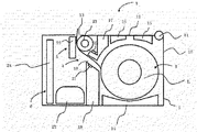
実施例1を図1ないし図6に基づいて説明する。図1は、本発明の実施例1に係るサーマルプリンター1の概略側面図であり、開閉カバー12がプリンターハウジング10に対して閉状態であるときの図である。図2は、開閉カバー12がプリンターハウジング10に対して開状態であるときの図である。サーマルプリンター1は、バッテリー内蔵のポータブルプリンターであり、プリンター本体2と、供給部3と、検出部4と、印字部5と、制御部6とを有する。
A first embodiment will be described with reference to FIGS. FIG. 1 is a schematic side view of the
実施例1で使用する印字媒体は、帯状の台紙上に所定間隔をおいて複数のラベルが仮着されたラベル連続体Lであり、ロール状に巻回されて使用される。 The printing medium used in Example 1 is a label continuum L in which a plurality of labels are temporarily attached on a belt-like mount at a predetermined interval, and is used after being wound in a roll shape.
プリンター本体2は、プリンターハウジング10と、カバー開閉軸11と、開閉カバー12と、ラベル排出口13とを有する。プリンターハウジング10は、底板と側板とを有し、側板の一端にはカバー開閉軸11が取り付けられるようになっている。開閉カバー12は、カバー開閉軸11に取り付けられ回動可能となり、プリンターハウジング10に対して図1に示す閉状態と図2に示す開状態とを形成する。プリンターハウジング10と開閉カバー12の他端部との間には、ラベル排出口13としての隙間が設けけられ、供給部3が設けられた搬送方向上流側から印字部5を経て印字が施されたラベル連続体Lがラベル排出口13が設けられた搬送方向下流側に向けて搬送され、プリンター本体2の外部へ排出されるようになっている。
The printer main body 2 includes a printer housing 10, a cover opening /
ラベル供給部3は、第一ロール支持部14と、第二ロール支持部15と、第三ロール支持部16とを有し、ロール状のラベル連続体Lを回転可能に保持する。第一ロール支持部14は、その一側面が円弧状に切り欠かれた薄板であり、複数の第一ロール支持部14が所定の間隔を空けて、前記円弧面がロール状のラベル連続体L側に向き、かつラベル連続体Lの繰出し方向と平行に、プリンターハウジング10に立設されている。また、第二ロール支持部15および第三ロール支持部16は、それぞれの一側面が、後述するプラテンローラー保持機構17の第四ロール支持部39と共に一の円弧を形成するように切り欠かれた薄板であり、開閉カバー12の内面に立設されている。複数の第二ロール支持部15は、開閉カバー12の一端側(搬送方向上流側)において、ラベルの幅方向に所定の間隔を空けて、開閉カバー12が閉状態の際に円弧面がラベル連続体Lに向き、かつラベル連続体Lの繰出し方向と平行となるように取り付けられている。複数の第三ロール支持部16は、それぞれ対応する第二ロール支持部15と同じ列上に、第二ロール支持部15、第三ロール支持部16、プラテンローラー保持機構17の第四ロール支持部39が一の円弧を描くように開閉カバー12の他端側(搬送方向下流側)に取り付けられている。これらロール支持部により供給部3内のロール状のラベル連続体Lとの接触面積を減らすことで、回転不可なくスムーズにラベル連続体Lを移送可能としている。
Label feed unit 3, a first roll support 14, a
ラベル検出部4は、検出器である発光器20および受光器21とを有する。受光器21は、プリンターハウジング10に設けられた第一のラベルガイド部18に取り付けられている。第一のラベルガイド部18は、ラベル連続体Lの表面側(印字面側)をガイドして、ラベル連続体Lのばたつきを抑え、搬送経路の一部として構成されている。
また、発光器20は、開閉カバー12の他端側に設けられたプラテンローラー保持機構17に取り付けられている。プラテンローラー保持機構17は、樹脂等の素材でできた部材であり、第三ロール支持部16とプラテンローラー23との間(印字部5の上流側近傍)に配置されている。また、第一のラベルガイド部18も、樹脂等の素材でできた部材であり、プリンターハウジング10に取り付けられ、第一ロール支持部14とバッテリー25との間に配置されている。
開閉カバー12が閉状態の際には、プラテンローラー保持機構17と第一のラベルガイド部18は互いに対向配置され、第一のラベルガイド部18と対向するプラテンローラー保持機構17の一部がラベル連続体Lの裏面側(台紙側)をガイドする第二のラベルガイド部37となる。この対向配置した両者の面は、印字部5に向かって互いに平行な斜面となっており、第一のラベルガイド部18と第二のラベルガイド部37により、ラベル連続体Lのラベル移送路19を形成するようになっている。発光器20は、ラベル移送路19上のラベル連続体Lの裏面側から発光するようにプラテンローラー保持機構17に取り付けられている。受光器21は、ラベル移送路19上のラベル連続体Lの表面側にある第1のラベルガイド18に取り付けられ、ラベル連続体Lに向けて発光器20から発光された透過光を受光するようになっている。
なお、透過型のセンサーとしたが、発光した光の反射量を受光する反射型センサーをプラテンローラー保持機構17に設けてもよい。また、反射型センサーおよび透過型センサーの発光器または受光器の一方をプラテンローラー保持機構17に設け、透過型センサーの発光器または受光器の他方を第一のラベルガイド部18に設けるようにしても良い。
The label detection unit 4 includes a light emitter 20 and a light receiver 21 that are detectors. The light receiver 21 is attached to a first
The light emitter 20 is attached to a platen
When the open /
Although a transmission type sensor is used, a reflection type sensor that receives a reflection amount of emitted light may be provided in the platen
ラベル印字部5は、サーマルヘッド22と、プラテンローラー23とを有している。サーマルヘッド22は、ラベル排出口13近傍のプリンターハウジング10に設けられている。プラテンローラー23は、開閉カバー12のプラテンローラー保持機構17に対して回転可能に取り付けられており、開閉カバー12が閉状態の時には、サーマルヘッド22表面の発熱素子とプラテンローラー23とが互いに対向配置される。
また、プリンターハウジング10には図示しない駆動モータを備え、開閉カバー12が閉状態でプラテンローラー23のギアと噛み合い、回転駆動を可能としている。
また、サーマルヘッド22は図示しないヘッドブラケットを有して、開閉カバー12が閉状態でこのヘッドブラケットの両側面に設けられたプラテン係合部によりプラテンローラー34の軸受35を回転可能に支持するように構成されている。
また、ヘッドブラケットには図示しない弾性部材が設けられ、プラテンローラー23とサーマルヘッド22によりラベル連続体Lを挟持した際に所定の押圧力でサーマルヘッド22をプラテンローラー23側に押圧して、ラベル連続体Lに印字を行うとともに、ラベル連続体Lをラベル排出口13へ移送するようになっている。
弾性部材は、プラテンローラー34の軸受35をプラテン係合部で支持する方向に付勢して、開閉カバー2の閉状態を維持し、弾性部材の付勢力に抗してヘッドブラケットを回動して、軸受35とプラテン係合部との係合を解除することにより、開閉カバー12を開放可能としている。
The label printing unit 5 includes a thermal head 22 and a
Further, the printer housing 10 is provided with a drive motor (not shown), and meshes with the gear of the
The thermal head 22 has a head bracket (not shown) so that the bearing 35 of the
Further, the head bracket is provided with an elastic member (not shown), and when the label continuous body L is sandwiched between the
The elastic member urges the bearing 35 of the
制御部6は、制御基板24とバッテリー25とを有する。制御基板24は、CPU、ROM、RAM等を有し、各部の動作の制御を行う。バッテリー25は、各部が動作するための電力を各部に供給する。 The control unit 6 includes a control board 24 and a battery 25. The control board 24 includes a CPU, a ROM, a RAM, and the like, and controls the operation of each unit. The battery 25 supplies power for operating each unit to each unit.
本実施例1のサーマルプリンター1は以上の構成を有し、ラベル連続体Lは、ラベル供給部3にて供給され、供給されたラベル連続体Lはラベル検出部4を通過してラベル印字部5に移送される。ラベル印字部5ではラベル連続体Lをサーマルヘッド22とプラテンローラー23とで挟み込み、所定の位置に印字が施される。印字が施された後、ラベル連続体Lは、ラベル排出口13から外部に排出される。
The
次に、開閉カバー12の周辺部をより具体的に説明する。図3は、開閉カバー12の裏側の斜視図である。開閉カバー12の内側面には、前述した第二ロール支持部15と、第三ロール支持部16と、ネジ孔30と、プラテンローラー保持用突出片31と、間隙32が設けられている。開閉カバー12の一端には、カバー開閉軸貫通孔12Aおよびカバー開閉軸貫通孔15Aが設けられ、金属の円柱軸であるカバー開閉軸11が挿通される。一対のネジ孔30は、複数の第三ロール支持部16の下流側に設けられた孔であり、図示しないネジを螺合してプラテンローラー保持機構17を開閉カバー12に取り付け固定するようになっている。
これら第二ロール支持部15および第三ロール支持部16は、プリンターハウジング10の第一ロール支持部14および後述するプラテンローラー保持機構17の第四ロール支持部39と共にラベル供給部3に装填されたロール状のラベル連続体Lの周面をガイドするロールガイドとして機能する。
また、プラテンローラー保持用突出片31は、カバー開閉軸11およびカバー開閉軸貫通孔12Aが設けられた側と反対の端の両側面に設けられ、プラテンローラー保持用突出片31と開閉カバー12との間には、間隙32が形成され、後述するプラテンローラー保持機構17のプラテンローラー保持部38が嵌るプラテンローラー挿入口32Aと、プラテンローラー23の軸33が貫通するプラテンローラー保持用孔32Bとを含む。
そして、図7に示すようにプラテンローラー挿入口32Aをプラテンローラー保持部38で塞ぐことにより、長孔形状のプラテンローラー保持用孔32Bとして形成される。
この長孔は、プラテンローラー軸33の軸径よりも長くなっており、プラテンローラー軸33は、長孔内で回転自在かつラベル連続体Lの移送方向に移動可能となっている。そして、開閉カバー12を閉状態とするときに、上述したヘッドブラケットのプラテン係合部によって、サーマルヘッド22とプラテンローラー23の相対的な位置合わせを行うことができる。すなわち、装置の組み付け誤差があっても長孔内でプラテンローラー34の位置を調整できるため、組み付け誤差の影響なくーマルヘッド22とプラテンローラー23の最適な位置あわせを可能としている。
Next, the peripheral part of the opening /
The second
The platen roller holding protruding
Then, as shown in FIG. 7, the platen
The long hole is longer than the shaft diameter of the
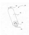
図4は、プラテンローラー23の斜視図であり、プラテンローラー23は、プラテンローラー軸33と、プラテンローラー本体34と、軸受35とを有する。プラテンローラー軸33は、ステンレス等の金属であり、円柱形状の金属棒の一端部が、断面D型にカットされ、この位置にプラテンローラー34のギア(図示せず)が固定される。プラテンローラー本体34は、中心軸が空孔の、例えばウレタンゴムやシリコーンゴムでできた弾性体である。空孔にプラテンローラー軸33が挿通して固定されており、プラテンローラー軸33が回転駆動されると、プラテンローラー本体34も共に回転駆動するようになっている。一対の軸受35はプラテンローラー軸33の両側かつプラテンローラー本体34の外側にそれぞれ間隙を空けて固定されている。
FIG. 4 is a perspective view of the
図5は、プラテンローラー保持機構17の斜視図である。プラテンローラー保持機構17は、プリンターハウジング10の幅方向と略等しい幅を有する部材であり、ラベルロール支持部36と、第二のラベルガイド部37と、プラテンローラー保持部38とを有する。
FIG. 5 is a perspective view of the platen
ラベルロール支持部36は、プラテンローラー保持機構17の一方の面に配された断面円弧状の面であり、第四ロール支持部39を有する。複数の第四ロール支持部39は、ラベル支持部36の面に垂直に起立させた板状部材であり、その上部の辺は、供給部3内のロール状のラベル連続体Lを回転可能に支持するために円弧状になっている。
また、プラテンローラー保持機構17には2つのネジ貫通孔40が設けられ、図示しないネジによりプラテンローラー保持機構17が開閉カバー12に取り付けられる。
The label
Further, the platen
第二のラベルガイド部37は、ラベルロール支持部36の反対面に配された面であり、上述の第一のラベルガイド部18とで搬送経路の一部を形成している。この第2のラベルガイドには検出部用窓41が設けられ、第二のラベルガイド部37およびラベルロール支持部36は、鋭角状に折り曲げられた折曲部17Aを介して互いに一体成形されている。このように鋭角状にすることで、ラベル供給部を円弧状により大きく設けることができるのでロール紙の支持もより安定して行うことができ、また、ラベル連続体Lをしごくことができ、かつ第一のラベルガイド部18と第二のラベルガイド部37との間隔であるラベル移送路が狭くなるので、ラベル連続体Lを印字部により正確に移送することができる。そして検出器が検出部用窓41の位置に検出器の一部を構成する発光器20を設け、狭い移送路内でラベル連続体Lのばたつきを抑えることができるので、高い精度でラベルの一検出を行うことができる。
The second
一対のプラテンローラー保持部38は、プラテンローラー保持機構17の両端に、ラベルロール支持部36および第二のラベルガイド部37の間かつ第二のラベルガイド部37の下部に配置されている。プラテンローラー保持部38は、プラテンローラー保持機構17と一体成形されており、湾曲形状に外方に突出した突出片である。その突出片は、プリンター本体2のプラテンローラー挿入口32Aに嵌合するようになっている。
The pair of platen
図6は、開閉カバー12にカバー開閉軸11、プラテンローラー23、プラテンローラー保持機構17を取り付けた際の斜視図である。開閉カバー12の周辺部は以上の構成を有し、一端に備えられたカバー開閉軸貫通孔12A、15Aにカバー開閉軸11が挿通され、開閉カバー12はプリンターハウジング10に対して回動自在となり、開閉カバー12はプリンターハウジング10に対して開閉可能となる。反対側の端には、プラテンローラー23のプラテンローラー本体34と軸受35との間にあるプラテンローラー軸33が、プラテンローラー保持用孔32Bに貫通し、プラテンローラー保持機構17のプラテンローラー保持部38がプラテンローラー挿入口32Aに嵌合することによって、プラテンローラー挿入口32Aが閉じられ、プラテンローラー23がプラテンローラー保持用孔32B内で回転可能に支持される。プラテンローラー保持機構17のラベルロール支持部36は、ロール状のラベル連続体Lを回転可能に支持し、複数の第四ロール支持部39は、対応する第二ロール支持部15および第三ロール支持部16と並び、一つの円弧を形成し、ラベル連続体Lの周囲を直線状で支持することで、面状で支持するよりも摩擦が少なくなり、ラベル連続体Lの移送を円滑に行うことができる。
FIG. 6 is a perspective view when the cover opening / closing
かくして、本発明の構成によれば、プラテンローラー保持機構にロール紙支持部およびロール紙検出部を設けてそれぞれ一体化させたので、各部が独立したものよりも、部品が少なくて済み、組み立ての簡便化、プリンターの小型化などの効果を奏することができる。 Thus, according to the configuration of the present invention, since the roll paper support part and the roll paper detection part are provided and integrated in the platen roller holding mechanism, each part has fewer parts than the independent parts, and Effects such as simplification and downsizing of the printer can be achieved.
1 サーマルプリンター(実施例1、図1)
2 プリンター本体
3 ラベル供給部
4 ラベル検出部
5 ラベル印字部
6 制御部
10 プリンターハウジング
11 カバー開閉軸
12 開閉カバー
12A カバー開閉軸貫通孔
13 ラベル排出口
14 第一ロール支持部
15 第二ロール支持部
15A カバー開閉軸貫通孔
16 第三ロール支持部
17 プラテンローラー保持機構
18 第一のラベルガイド部
19 ラベル移送路
20 発光器
21 受光器
22 サーマルヘッド
23 プラテンローラー
24 制御基板
25 バッテリー
30 ネジ孔
31 プラテンローラー保持用突出片
32 間隙
32A プラテンローラー挿入口
32B プラテンローラー保持用孔
33 プラテンローラー軸
34 プラテンローラー本体
35 軸受
36 ラベルロール支持部
37 第二のラベルガイド部
38 プラテンローラー保持部
39 第四ロール支持部
40 ネジ貫通孔
41 検出部用窓
1 Thermal printer (Example 1, Fig. 1)
2 Printer body 3 Label supply unit 4 Label detection unit 5 Label printing unit 6 Control unit 10
Claims (22)
前記プリンター本体に対して開閉可能に設けられた開閉カバーと、
前記プリンター本体に設けられ、シート状部材に印字を施すサーマルヘッドと、
前記開閉カバーに設けられ、閉止状態で前記サーマルヘッドと対向する位置に設けられて、前記シート状部材を搬送するプラテンローラーと、
前記プラテンローラーを前記開閉カバーに着脱可能に保持するとともに、前記供給部のロール状のシート状部材を回転可能に案内する断面円弧状の面を有するラベルロール支持部を備えるプラテンローラー保持機構と、を有することを特徴とするプリンター。 A printer main body having a supply unit for rotatably holding a roll-like sheet-like member;
An opening / closing cover provided to be openable / closable with respect to the printer body;
A thermal head provided in the printer body for printing on a sheet-like member;
A platen roller that is provided on the opening and closing cover, is provided at a position facing the thermal head in a closed state, and conveys the sheet-like member;
A platen roller holding mechanism comprising a label roll support portion having a cross-section arc-shaped surface that rotatably holds the platen roller on the opening / closing cover and rotatably guides a roll-like sheet-like member of the supply portion; A printer comprising:
前記プラテンローラー保持機構は、前記挿入口を塞ぐプラテンローラー保持部を有することを特徴とする請求項1ないし4のいずれかに記載のプリンター。 The opening / closing cover has an insertion port that allows the shaft of the platen roller to be inserted and removed,
The printer according to claim 1, wherein the platen roller holding mechanism includes a platen roller holding unit that closes the insertion port.
前記プリンター本体に対して開閉可能に設けられた開閉カバーと、
前記プリンター本体に設けられ、シート状部材に印字を施すサーマルヘッドと、
前記開閉カバーに設けられ、閉止状態で前記サーマルヘッドと対向する位置に設けられて、前記シート状部材を搬送するプラテンローラーと、
前記開閉カバーに取付けられたときに前記プラテンローラーを前記開閉カバーに保持し、前記開閉カバーから外されたときに前記プラテンローラーを前記開閉カバーから開放するように構成されているとともに、前記供給部のロール状のシート状部材を回転可能に案内する断面円弧状の面を有するラベルロール支持部を備えるプラテンローラー保持機構と、を有することを特徴とするプリンター。 A printer main body having a supply unit for rotatably holding a roll-like sheet-like member;
An opening / closing cover provided to be openable / closable with respect to the printer body;
A thermal head provided in the printer body for printing on a sheet-like member;
A platen roller that is provided on the opening and closing cover, is provided at a position facing the thermal head in a closed state, and conveys the sheet-like member;
The platen roller is held by the opening / closing cover when attached to the opening / closing cover, and is configured to open the platen roller from the opening / closing cover when removed from the opening / closing cover, and the supply unit A platen roller holding mechanism including a label roll support portion having a circular arc-shaped section for rotatably guiding a roll-shaped sheet-like member.
前記プラテンローラー保持機構は、第2のラベルガイド部を有し、
前記第2のラベルガイド部は、前記開閉カバーが閉止状態の際に前記第1のラベルガイド部と対向する位置に配置され、前記シート状部材を案内することを特徴とする請求項8ないし10のいずれかに記載のプリンター。 A first label guide part,
The platen roller holding mechanism has a second label guide part,
Said second label guide portion, the cover is arranged at a position facing the first label guide portion when the closed state, the preceding claims 8, characterized in that for guiding the sheet-like member 10 The printer according to any one of the above.
前記プラテンローラー保持機構は、前記挿入口を塞ぐプラテンローラー保持部を有することを特徴とする請求項8ないし11のいずれかに記載のプリンター。 The opening / closing cover has an insertion port that allows the shaft of the platen roller to be inserted and removed,
The printer according to claim 8 , wherein the platen roller holding mechanism includes a platen roller holding portion that closes the insertion port.
前記プリンター本体に対して開閉可能に設けられた開閉カバーと、
前記プリンター本体に設けられ、前記印字媒体に印字を施すサーマルヘッドと、
前記開閉カバーに着脱可能に設けられ、閉止状態で前記サーマルヘッドと対向する位置に設けられて、前記印字媒体を搬送するプラテンローラーと、
前記開閉カバーに取付けられたときに前記プラテンローラーを前記開閉カバーに保持し、前記開閉カバーから外されたときに前記プラテンローラーを前記開閉カバーから開放するように構成されているとともに、前記印字媒体を案内するプラテンローラー保持機構と、を有することを特徴とするプリンター。 A printer body having a supply unit for supplying a print medium wound in a roll;
An opening / closing cover provided to be openable / closable with respect to the printer body;
A thermal head provided on the printer body for printing on the print medium ;
A platen roller that is detachably provided on the opening / closing cover, is provided at a position facing the thermal head in a closed state, and conveys the print medium ;
The printing medium is configured to hold the platen roller on the opening / closing cover when attached to the opening / closing cover, and to release the platen roller from the opening / closing cover when removed from the opening / closing cover. A platen roller holding mechanism for guiding the printer.
前記印字媒体のロール状部分を前記第1のロール支持部の断面円弧状の面で回転可能に案内する、
請求項15に記載のプリンター。 The platen roller holding mechanism is provided with a first roll support part having an arc-shaped cross section,
A roll-shaped portion of the print medium is rotatably guided by a circular arc-shaped surface of the first roll support portion;
The printer according to claim 15 .
請求項15に記載のプリンター。The printer according to claim 15.
請求項16に記載のプリンター。The printer according to claim 16.
前記プラテンローラー保持機構は、前記挿入口を塞ぐプラテンローラー保持部を有することを特徴とする請求項15ないし19のいずれかに記載のプリンター。 The opening / closing cover has an insertion port that allows the shaft of the platen roller to be inserted and removed,
The printer according to claim 15 , wherein the platen roller holding mechanism includes a platen roller holding unit that closes the insertion port.
Priority Applications (9)
| Application Number | Priority Date | Filing Date | Title |
|---|---|---|---|
| JP2013063676A JP6096023B2 (en) | 2013-03-26 | 2013-03-26 | printer |
| PCT/JP2013/084826 WO2014155881A1 (en) | 2013-03-26 | 2013-12-26 | Printer |
| CN201610886036.3A CN107081969B (en) | 2013-03-26 | 2013-12-26 | Printer |
| EP13880607.0A EP2979879B1 (en) | 2013-03-26 | 2013-12-26 | Printer |
| CN201380075026.6A CN105050822B (en) | 2013-03-26 | 2013-12-26 | Printer |
| US14/779,734 US9821572B2 (en) | 2013-03-26 | 2013-12-26 | Printer |
| EP17203596.6A EP3308970B1 (en) | 2013-03-26 | 2013-12-26 | Printer |
| US15/783,104 US10272701B2 (en) | 2013-03-26 | 2017-10-13 | Printer |
| US16/354,903 US11059305B2 (en) | 2013-03-26 | 2019-03-15 | Printer |
Applications Claiming Priority (1)
| Application Number | Priority Date | Filing Date | Title |
|---|---|---|---|
| JP2013063676A JP6096023B2 (en) | 2013-03-26 | 2013-03-26 | printer |
Related Child Applications (1)
| Application Number | Title | Priority Date | Filing Date |
|---|---|---|---|
| JP2017025827A Division JP6448678B2 (en) | 2017-02-15 | 2017-02-15 | printer |
Publications (3)
| Publication Number | Publication Date |
|---|---|
| JP2014188708A JP2014188708A (en) | 2014-10-06 |
| JP2014188708A5 JP2014188708A5 (en) | 2015-11-19 |
| JP6096023B2 true JP6096023B2 (en) | 2017-03-15 |
Family
ID=51622912
Family Applications (1)
| Application Number | Title | Priority Date | Filing Date |
|---|---|---|---|
| JP2013063676A Active JP6096023B2 (en) | 2013-03-26 | 2013-03-26 | printer |
Country Status (5)
| Country | Link |
|---|---|
| US (3) | US9821572B2 (en) |
| EP (2) | EP2979879B1 (en) |
| JP (1) | JP6096023B2 (en) |
| CN (2) | CN105050822B (en) |
| WO (1) | WO2014155881A1 (en) |
Cited By (1)
| Publication number | Priority date | Publication date | Assignee | Title |
|---|---|---|---|---|
| KR20200127489A (en) * | 2019-05-02 | 2020-11-11 | 포항공과대학교 산학협력단 | Artificial vascular model including lubricating layer and elastic layer, and fabricating method thereof |
Families Citing this family (11)
| Publication number | Priority date | Publication date | Assignee | Title |
|---|---|---|---|---|
| JP6096023B2 (en) | 2013-03-26 | 2017-03-15 | サトーホールディングス株式会社 | printer |
| US9493017B2 (en) * | 2015-02-13 | 2016-11-15 | Zih Corp. | Modular print drive assembly and platen assembly |
| JP6886233B2 (en) * | 2015-09-09 | 2021-06-16 | 富士通コンポーネント株式会社 | Printer equipment |
| JP6684387B2 (en) * | 2016-04-07 | 2020-04-22 | ヒューレット−パッカード デベロップメント カンパニー エル.ピー.Hewlett‐Packard Development Company, L.P. | Door extension |
| JP6829008B2 (en) * | 2016-05-24 | 2021-02-10 | 富士通コンポーネント株式会社 | Printer |
| WO2019065653A1 (en) * | 2017-09-26 | 2019-04-04 | サトーホールディングス株式会社 | Printer |
| JP7031439B2 (en) * | 2018-03-30 | 2022-03-08 | ブラザー工業株式会社 | Printing equipment |
| JP2019217635A (en) * | 2018-06-15 | 2019-12-26 | 富士通コンポーネント株式会社 | Printer device |
| CN108909189A (en) * | 2018-07-26 | 2018-11-30 | 深圳怡化电脑股份有限公司 | A kind of printing equipment |
| WO2022107661A1 (en) | 2020-11-18 | 2022-05-27 | サトーホールディングス株式会社 | Printer |
| JP2022080715A (en) * | 2020-11-18 | 2022-05-30 | サトーホールディングス株式会社 | Printer |
Family Cites Families (28)
| Publication number | Priority date | Publication date | Assignee | Title |
|---|---|---|---|---|
| JPS60142943U (en) | 1984-03-06 | 1985-09-21 | 株式会社田村電機製作所 | printer |
| JPH0264056U (en) * | 1988-11-04 | 1990-05-14 | ||
| JP2584078B2 (en) | 1989-12-28 | 1997-02-19 | 株式会社テック | Platen support device in line thermal printer |
| JPH0430952U (en) | 1990-07-05 | 1992-03-12 | ||
| JPH0535385A (en) | 1991-07-30 | 1993-02-12 | Canon Inc | Key code converter |
| JP2545854Y2 (en) * | 1991-10-18 | 1997-08-27 | グラフテック株式会社 | Roller support device for recording device |
| JPH07132653A (en) | 1993-11-11 | 1995-05-23 | Fuji Photo Film Co Ltd | Thermal printer |
| US6118469A (en) | 1995-11-21 | 2000-09-12 | Seiko Epson Corporation | Thermal printer |
| JP3487397B2 (en) * | 1997-04-09 | 2004-01-19 | 理想科学工業株式会社 | Thermal recording device |
| US6004053A (en) * | 1998-09-11 | 1999-12-21 | Comtec Informationsystems, Inc. | Printer apparatus |
| JP4543494B2 (en) * | 2000-04-19 | 2010-09-15 | セイコーエプソン株式会社 | Printer |
| JP3334704B2 (en) * | 2000-04-27 | 2002-10-15 | セイコーエプソン株式会社 | Printer |
| JP2002166610A (en) | 2000-11-30 | 2002-06-11 | Toshiba Tec Corp | Printer |
| JP3997821B2 (en) | 2002-04-10 | 2007-10-24 | セイコーエプソン株式会社 | Printer and control method thereof |
| JP2005081730A (en) * | 2003-09-09 | 2005-03-31 | Ishida Co Ltd | Label printer |
| US7284922B2 (en) * | 2004-08-09 | 2007-10-23 | Seiko Epson Corporation | Label printer |
| JP4244960B2 (en) * | 2005-05-25 | 2009-03-25 | ブラザー工業株式会社 | Inkjet recording device |
| JP4207955B2 (en) * | 2005-12-27 | 2009-01-14 | ブラザー工業株式会社 | Inkjet recording device |
| JP2009086923A (en) * | 2007-09-28 | 2009-04-23 | Brother Ind Ltd | Tag label creation device |
| JP2010167680A (en) | 2009-01-23 | 2010-08-05 | Sato Knowledge & Intellectual Property Institute | Cutter unit and printer |
| JP4950261B2 (en) * | 2009-09-04 | 2012-06-13 | 東芝テック株式会社 | Platen roller support structure and printer |
| JP2011111311A (en) * | 2009-11-30 | 2011-06-09 | Seiko Epson Corp | Recording medium processing device |
| EP2390099B1 (en) * | 2010-05-31 | 2016-04-20 | Brother Kogyo Kabushiki Kaisha | Printer |
| JP5993161B2 (en) * | 2012-02-29 | 2016-09-14 | サトーホールディングス株式会社 | Opening and closing device and printer having the opening and closing device |
| CN102689523B (en) * | 2012-05-29 | 2014-05-21 | 福建联迪商用设备有限公司 | Electronic equipment with printing function |
| JP6096023B2 (en) * | 2013-03-26 | 2017-03-15 | サトーホールディングス株式会社 | printer |
| JP6991879B2 (en) * | 2018-02-13 | 2022-01-13 | 東芝テック株式会社 | Printer |
| JP6694940B2 (en) | 2018-12-04 | 2020-05-20 | サトーホールディングス株式会社 | printer |
-
2013
- 2013-03-26 JP JP2013063676A patent/JP6096023B2/en active Active
- 2013-12-26 WO PCT/JP2013/084826 patent/WO2014155881A1/en active Application Filing
- 2013-12-26 EP EP13880607.0A patent/EP2979879B1/en active Active
- 2013-12-26 EP EP17203596.6A patent/EP3308970B1/en active Active
- 2013-12-26 US US14/779,734 patent/US9821572B2/en active Active
- 2013-12-26 CN CN201380075026.6A patent/CN105050822B/en active Active
- 2013-12-26 CN CN201610886036.3A patent/CN107081969B/en active Active
-
2017
- 2017-10-13 US US15/783,104 patent/US10272701B2/en active Active
-
2019
- 2019-03-15 US US16/354,903 patent/US11059305B2/en active Active
Cited By (2)
| Publication number | Priority date | Publication date | Assignee | Title |
|---|---|---|---|---|
| KR20200127489A (en) * | 2019-05-02 | 2020-11-11 | 포항공과대학교 산학협력단 | Artificial vascular model including lubricating layer and elastic layer, and fabricating method thereof |
| KR102232226B1 (en) * | 2019-05-02 | 2021-03-25 | 포항공과대학교 산학협력단 | Artificial vascular model including lubricating layer and elastic layer, and fabricating method thereof |
Also Published As
| Publication number | Publication date |
|---|---|
| CN107081969B (en) | 2018-09-11 |
| US11059305B2 (en) | 2021-07-13 |
| CN107081969A (en) | 2017-08-22 |
| CN105050822B (en) | 2017-07-28 |
| US9821572B2 (en) | 2017-11-21 |
| US20190210382A1 (en) | 2019-07-11 |
| EP3308970B1 (en) | 2019-08-21 |
| JP2014188708A (en) | 2014-10-06 |
| CN105050822A (en) | 2015-11-11 |
| WO2014155881A1 (en) | 2014-10-02 |
| US10272701B2 (en) | 2019-04-30 |
| US20160052304A1 (en) | 2016-02-25 |
| EP2979879A4 (en) | 2016-10-12 |
| EP2979879B1 (en) | 2018-03-07 |
| US20180043706A1 (en) | 2018-02-15 |
| EP2979879A1 (en) | 2016-02-03 |
| EP3308970A1 (en) | 2018-04-18 |
Similar Documents
| Publication | Publication Date | Title |
|---|---|---|
| JP6096023B2 (en) | printer | |
| JP2014188708A5 (en) | ||
| EP2363292B1 (en) | Label separator and label printer incorporating the label separator | |
| JP2011032008A (en) | Supply shaft device of printing paper, supply method thereof and printer for printing paper | |
| JP4776023B2 (en) | Label printer | |
| JP6694940B2 (en) | printer | |
| JP2014037294A (en) | Roll paper supply device and printer | |
| KR101593037B1 (en) | Apparatus for protecting paper skew of printer | |
| JP2009286002A (en) | Cover supporting apparatus | |
| JP2011207549A (en) | Roll paper printer | |
| JP2015123625A (en) | Printer | |
| JP6448678B2 (en) | printer | |
| JP5395103B2 (en) | Label printer | |
| JP6886532B2 (en) | printer | |
| JP5613703B2 (en) | Label peeling device | |
| JP2011194614A (en) | End detecting device in printer and end detecting method | |
| JP2009179013A (en) | Printer | |
| JP2013216470A (en) | Label peeling mechanism and printer | |
| JP5679184B2 (en) | Printer | |
| JP6966243B2 (en) | Printer | |
| JP6146216B2 (en) | Conveying apparatus and recording apparatus | |
| JP3954441B2 (en) | Printer device system including automatic paper feeder and paper holder | |
| JP2014034152A (en) | Printer | |
| JP2011207550A (en) | Roll paper printer | |
| JP2015000479A (en) | Printer |
Legal Events
| Date | Code | Title | Description |
|---|---|---|---|
| A521 | Request for written amendment filed |
Free format text: JAPANESE INTERMEDIATE CODE: A523 Effective date: 20150929 |
|
| A621 | Written request for application examination |
Free format text: JAPANESE INTERMEDIATE CODE: A621 Effective date: 20151117 |
|
| A131 | Notification of reasons for refusal |
Free format text: JAPANESE INTERMEDIATE CODE: A131 Effective date: 20160802 |
|
| A521 | Request for written amendment filed |
Free format text: JAPANESE INTERMEDIATE CODE: A523 Effective date: 20160920 |
|
| TRDD | Decision of grant or rejection written | ||
| A01 | Written decision to grant a patent or to grant a registration (utility model) |
Free format text: JAPANESE INTERMEDIATE CODE: A01 Effective date: 20170117 |
|
| A61 | First payment of annual fees (during grant procedure) |
Free format text: JAPANESE INTERMEDIATE CODE: A61 Effective date: 20170215 |
|
| R150 | Certificate of patent or registration of utility model |
Ref document number: 6096023 Country of ref document: JP Free format text: JAPANESE INTERMEDIATE CODE: R150 |
|
| R250 | Receipt of annual fees |
Free format text: JAPANESE INTERMEDIATE CODE: R250 |
|
| R250 | Receipt of annual fees |
Free format text: JAPANESE INTERMEDIATE CODE: R250 |
|
| R250 | Receipt of annual fees |
Free format text: JAPANESE INTERMEDIATE CODE: R250 |
|
| R250 | Receipt of annual fees |
Free format text: JAPANESE INTERMEDIATE CODE: R250 |
|
| R250 | Receipt of annual fees |
Free format text: JAPANESE INTERMEDIATE CODE: R250 |