JP6991827B2 - Anti-aircraft sign - Google Patents
Anti-aircraft sign Download PDFInfo
- Publication number
- JP6991827B2 JP6991827B2 JP2017199852A JP2017199852A JP6991827B2 JP 6991827 B2 JP6991827 B2 JP 6991827B2 JP 2017199852 A JP2017199852 A JP 2017199852A JP 2017199852 A JP2017199852 A JP 2017199852A JP 6991827 B2 JP6991827 B2 JP 6991827B2
- Authority
- JP
- Japan
- Prior art keywords
- aircraft
- sign
- ground
- marker
- aerial
- Prior art date
- Legal status (The legal status is an assumption and is not a legal conclusion. Google has not performed a legal analysis and makes no representation as to the accuracy of the status listed.)
- Active
Links
Images


Landscapes
- Length Measuring Devices By Optical Means (AREA)
Description
本発明は、対空標識に関し、特に、空中写真測量に好適な対空標識に関する。 The present invention relates to an anti-aircraft marker, and more particularly to an anti-aircraft marker suitable for aerial photographic surveying.
従来、公共測量等では、高度の高い飛行機での空中写真測量が利用されてきたが、近年、明かり工事においてもドローン等のUAVによる空中写真測量が主流となりつつある。UAVによる空中写真測量では、例えば、特許文献1に示すような平板状の対空標識が測量対象となる工事範囲に複数水平状態で配置される。そして、UAVを利用して工事範囲を撮影し、工事範囲に設けられた基準点から対空標識の位置を地上測量することで、空中写真に対して地上の座標の対応付けがなされる。
Conventionally, aerial photo surveying by a high-altitude airplane has been used for public surveying and the like, but in recent years, aerial photo surveying by UAV such as a drone is becoming mainstream even in lighting construction. In the aerial photograph survey by UAV, for example, a flat plate-shaped anti-aircraft marker as shown in
しかしながら、従来の対空標識は、平板状であるとともに水平に配置されているため、空中写真の撮影高度によっては、空中写真を見ただけでは撮影された方向や向き、地形の傾斜等の状態等が分かりにくいという問題がある。空中写真測量では、所定範囲が重複するように撮影された2つの空中写真をステレオ写真としてコンピュータにより処理することにより、工事範囲の地形形状を復元しているが、空中写真に対応点として設けられた対空標識の向き等の変化が分かりにくいと、地形の3次元化の処理において誤差が生じ、地形の3次元化の処理に時間を要したり、測量精度が低下したりする等の問題が生じ易い。
本発明では、空中写真測量における精度を向上可能な対空標識を提供することを目的とする。
However, since the conventional anti-aircraft sign is flat and horizontally arranged, depending on the shooting altitude of the aerial photograph, the direction and direction in which the aerial photograph was taken, the state of the slope of the terrain, etc., etc. There is a problem that it is difficult to understand. In aerial photogrammetry, the topographical shape of the construction area is restored by processing two aerial photographs taken so as to overlap a predetermined range as stereo photographs by a computer, but it is provided as a corresponding point in the aerial photographs. If it is difficult to understand the change in the direction of the anti-aircraft sign, an error will occur in the process of making the terrain three-dimensional, and there will be problems such as the time required for the process of making the terrain three-dimensional and the measurement accuracy will decrease. It is easy to occur.
It is an object of the present invention to provide an anti-aircraft marker capable of improving the accuracy in aerial photographic surveying.
上記課題を解決するための対空標識の構成として、空中写真測量における標定点として設けられる多角錘形状の対空標識であって、錐体の錐面を構成するそれぞれの頂点から延長し、対辺を2等分する直線により複数の領域に区画され、互いに隣接する領域同士の色彩が異なる構成とした。
本構成によれば、錐面に施された色彩を明瞭に空中写真に写り込ませることができ、撮影された空中写真をつなぎ合わせる後段の処理において、錐面における色彩の境界線や境界点、立体形状の稜線等を対応点として利用して空中写真をつなぎ合わせることができるので、空中写真測量の測量精度を向上させることができる。また、錐体が多角錐であるので、錐面における色彩の境界線や境界点、錐面の稜線等を対応点として利用して空中写真をつなぎ合わせることができるので、空中写真測量の測量精度を向上させることができる。
また、対空標識の他の構成として、頂部に地上測量用のターゲットを備える構成としたので、空中写真に地上測量用のターゲットも撮影されるため、空中写真と地上との関係を
紐付けする作業において同一の地物に基づいて空中写真を地上の座標系に対応付けが可能となり、空中写真測量の精度をより向上させることができる。
また、対空標識の他の構成として、多角錘形状における接地面は、複数の領域に区画され、互いに隣接する領域同士の色彩が異なるようにしても良い。
As a configuration of the anti-aircraft marker for solving the above problem, it is a polygonal weight-shaped anti-aircraft marker provided as a control point in aerial photography, and is extended from each vertex constituting the pyramid surface of the cone, and the opposite side is set to 2. It is divided into a plurality of areas by a straight line that divides it into equal parts, and the colors of the areas adjacent to each other are different.
According to this configuration, the colors applied to the conical surface can be clearly reflected in the aerial photograph, and in the subsequent processing of joining the aerial photographs taken, the boundary line or boundary point of the color on the conical surface, Since it is possible to connect aerial photographs by using a three-dimensional ridgeline or the like as a corresponding point, it is possible to improve the measurement accuracy of aerial photogrammetry. In addition, since the cone is a polygonal cone, it is possible to connect aerial photographs using the boundary lines and boundaries of colors on the cone surface, the ridgeline of the cone surface, etc. as corresponding points, so that the measurement accuracy of aerial photogrammetry can be achieved. Can be improved.
In addition, as another configuration of the anti-aircraft sign, since the target for ground survey is provided at the top, the target for ground survey is also taken in the aerial photograph, so the work of linking the relationship between the aerial photograph and the ground. In, it is possible to associate an aerial photograph with a coordinate system on the ground based on the same feature, and it is possible to further improve the accuracy of aerial photogrammetry.
Further, as another configuration of the anti-aircraft marker, the ground plane in the polygonal weight shape may be divided into a plurality of regions, and the colors of the regions adjacent to each other may be different.
図1は、対空標識の一実施形態を示す斜視図及び展開図である。図2は、対空標識1の5面図(正面,上下左右の5方向)である。図1に示すように、本実施形態に係る対空標識1は、全体形状が立体の頂点(頂部)A~Dを有する正三角錐として形成される。
FIG. 1 is a perspective view and a developed view showing an embodiment of an anti-aircraft sign. FIG. 2 is a five-view view (front, up, down, left, and right) of the
図1,図2に示すように、頂部Aから裾広がりに延びる錐面としての面S1~S4には、空中からの視認性を向上させるための色彩が施される。なお、本実施形態では、各面S1~S4には、同一の配色パターンが施されるものとして説明する。図2(ア)に示すように、面S1は、頂部Aから延長し、対辺である辺BCを2等分する直線L1と、頂部Bから延長し、対辺である辺ACを2等分する直線L2と、頂部Cから延長し、対辺である辺ABを2等分する直線L3とにより、複数の三角形の領域r1~r6に区画される。また、他の面S2~S4も面S1と同様に、各頂部A~Dから延長し、対辺を2等分する複数の直線により領域r1~r6に区画される。 As shown in FIGS. 1 and 2, the surfaces S1 to S4 as conical surfaces extending from the top A to the hem are colored to improve visibility from the air. In this embodiment, it is assumed that the same color scheme is applied to each of the surfaces S1 to S4. As shown in FIG. 2A, the surface S1 extends from the top A and divides the opposite side BC into two equal parts L1, and extends from the top B and divides the opposite side AC into two equal parts. It is divided into a plurality of triangular regions r1 to r6 by a straight line L2 and a straight line L3 that extends from the top C and bisects the opposite side AB. Further, the other surfaces S2 to S4 also extend from the tops A to D and are divided into regions r1 to r6 by a plurality of straight lines that bisect the opposite sides in the same manner as the surfaces S1.
各図に示すように、区画された複数の領域r1~r6には、隣接する領域同士が互いに異なるように白色又は黒色に着色されている。また、各面S1~S4が同一の配色パターンにより着色されていることにより、同一の面内において隣接する領域r1~r6のみならず、稜線を挟んで隣接する領域同士も異なる着色となる。ここで言う隣接する領域とは、同一面内において領域r1~r6が、線(本例では直線L1~L3)によって接しているもの、或いは、稜線Fによって接しているものをいい、点で接しているものは含まない。 As shown in each figure, the plurality of partitioned regions r1 to r6 are colored white or black so that adjacent regions are different from each other. Further, since each of the surfaces S1 to S4 is colored by the same color scheme, not only the adjacent regions r1 to r6 in the same surface but also the adjacent regions across the ridge line are colored differently. The adjacent regions referred to here are those in which the regions r1 to r6 are in contact with each other by a line (straight line L1 to L3 in this example) or by a ridge line F in the same plane, and are in contact with each other at a point. Does not include what is.
各領域r1~r6の色彩は、白色又は黒色の組み合わせに限定されず、地物の色彩に対して明確に異なる色彩を組み合わせたものであれば良い。また、隣接する領域についての異なる色彩の組み合わせとしては、反対色の関係にある組み合わせが好ましい。このような色彩を施すことにより、撮影された空中写真から対空標識1を視認し易くなる。
The color of each region r1 to r6 is not limited to the combination of white or black, and may be a combination of colors that are clearly different from the color of the feature. Further, as a combination of different colors for adjacent regions, a combination having a relationship of opposite colors is preferable. By applying such a color, the
対空標識1の一辺の寸法は例えば50cmに設定されているが、その寸法は、対空標識1を空中写真上で明瞭に識別できる寸法であれば良い。例えば、航空機のように高い高度から撮影する場合には全体形状が大きくなるように設定し、ドローン等のように低い高度から撮影する場合には全体形状を小さく形成することもできる。
The dimension of one side of the
対空標識1は、例えば、ベニヤ板や樹脂板等の板状の素材により中空状、或いは中実に形成しても良い。また、対空標識1の素材は、利用形態に応じて選定しても良い。例えば、環境に負荷を与えない素材を用いることで、対空標識1を回収する手間を省くことができる。環境に負荷を与えない素材とは、自然界の力によって分解される素材をいい、地上に放置した状態で微生物や雨等によって分解されるものをいう。
The
本実施形態に係る対空標識1は、面S1~S4のいずれかを接地面として直接地表面に設置される。従来の平板状の(対空)標識では、色彩の施された面を水平に設置することが求められていたが、対空標識1は、地表面から立ち上がる錐面を備える立体形状であるため、上空のいずれの方向から撮影しても、いずれかの面が空中写真として明瞭に識別可能となると共に、形状(対空標識1の全体としての形状や各面S1~S4の形状、或いは各面S1~S4に区画された領域r1~r6の形状等)の見え方の変化が大きく、地表面の傾きの状態が把握し易くなるため、設置における水平姿勢の維持(水平な地表面に設置したときを想定した状態)が要求されず、傾斜地等にそのまま設置することができる。また、空中写真に写り込む各面S1~S4には、上述のようなパターンの色彩が施されているため、同一範囲を含むように連続して撮影された空中写真をステレオ写真としてコンピュータにより処理し、地形形状をコンピュータ内で復元する場合、各空中写真に写り込んだ対空標識1の各面における色彩の境界線L1~L3、境界点P、或いは稜線Fや頂部A~Dを明確に共通する対応点として用いることができ、空中写真測量の精度を向上させることができる。
The
図2(イ)に示すように、例えば、面S4を接地面として対空標識1を直上から撮影した場合、上空から表面(例えばS1~S3)に施された白色と黒色の色彩を明瞭に空中写真に写り込ませることができる。従って、撮影された空中写真をつなぎ合わせる後段の処理において、各面S1~S3における色彩の境界線L1~L3や境界点P、面S1~S3同士の立体形状の稜線F等を対応点として利用することができる。
As shown in FIG. 2A, for example, when the
また、対空標識1は立体形状であるので、空中写真と地上座標との対応付けを行う際の現地調査(測量)において、地上から対空標識1の位置を容易に視認できるので、従来必要であった対空標識1の探索という手間を省くことができる。例えば、公共測量のような広範囲の空中写真測量では、2次元の平板の対空標識であったため、現地調査では対空標識に近づかないと見つけられないことが多く、時間を要する作業であったが、本実施形態の対空標識1は、立体形状であるため、現地調査において発見し易い。
Further, since the
図3は、対空標識1の頂部Aに地上測量用のターゲット10を設置した例を示す。同図に示すように、ターゲット10としては、地上測量において使用されるトータルステーション等による光波測距に用いる反射シート、ミラーやプリズム等が採用できる。ターゲット10の好ましい形態としては、360°の方向から利用できるもの、例えば、外周面に複数のミラーが配置された円筒状や球形状のものを用いると良い。このようなターゲット10を用いることにより、360°いずれの方向からも対空標識1の位置を測量することができる。なお、ターゲット10は、対空標識1の全ての頂部に設けても良く、又、一部の頂部に設けても良い。また、ターゲット10の取付形態は、対空標識1に常設しても着脱可能に設けても良い。
FIG. 3 shows an example in which a
対空標識1は、立体的であるため、例えば、ターゲット10を頂部A等に取り付けることにより、その配置された位置(座標)を直接地上測量することができる。これにより、対空標識1の位置を、地上に設定された基準点に基づいて地上の座標系に対応させることができる。
Since the
また、ターゲット10をあらかじめ取り付けた対空標識1を地上に配置しておくことにより、測量作業者が一人であっても標定点として設けた対空標識1の位置を簡単に測量することができる。即ち、従来における現地調査において、トータルステーション等の光波測距儀により地上測量する際に、一人の測量作業者がターゲットとともに対空標識のもとに移動し、もう一人の測量作業者が測量機器を操作しなくてはならなかったが、ターゲット10を対空標識まで運ぶための測量作業者の人員を削減できる。
Further, by arranging the
また、対空標識1に設けられたターゲット10は、空中写真にも写り込むため、空中写真に写されたターゲット10の位置に基づいて、地上の座標を結び付けることができるので、空中写真測量における測量精度を向上させることができる。
Further, since the
なお、ターゲット10が、空中写真に明確に撮影されていなくても、図2(イ)に示すように、頂部Aを囲む色彩によって、ターゲット10の位置が特定できるので、空中写真と地上との座標の結び付きの精度を低下させることはない。
Even if the
このように、対空標識1にターゲット10を取り付けておくことにより、単に地上から対空標識1を視認できるだけでなく、航空機やUAV等による空中写真の撮影と同時に、地上における測量作業を同時に進行できるので、測量に要する手間や時間を短縮することができる。
By attaching the
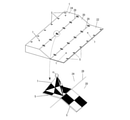
図4は、空中写真測量により造成後の法面20の仕上がり形状を測量するときの対空標識1の使用例を示している。図4は、従来の矩形平面状の標識5と、本実施形態に係る対空標識1とを併用した例を示す。具体的には、標識5を法面20、下段面22、上段面24、法面20と下段面22との境界線26、法面20と上段面24との境界線28に沿って複数配置している。また、対空標識1は、図4の拡大図に示すように、先に配置された標識5に重ねて配置される場合や、下段面22、上段面24に点在して複数配置される場合がある。各対空標識1の頂部Aには、図3に示すように、地上測量用のターゲット10が取り付けられている。
FIG. 4 shows an example of using the
そして、法面20を含む下段面22側及び上段面24側の複数の対空標識1を含むように法面20の延長方向に沿って、ドローンを飛行させることにより、各空中写真同士に所定の重複が得られるように、造成範囲を撮影する。
撮影された空中写真は、画像データとしてコンピュータにより対空標識1及び標識5に基づいて位置合わせされ、撮影範囲の3次元の地形データが生成される。
Then, by flying the drone along the extension direction of the
The aerial photograph taken is aligned as image data based on the
図5は、ターゲット10を備えた対空標識1の例示図である。図5に示すように、対空標識1に取り付けられたターゲット10を用いて、対空標識1の位置をトータルステーション等の測量機器12を用いて地上から測量することにより、空中写真に基づいて生成された地形データにおける対空標識1の(地球上における)座標位置が特定される。これにより、空中写真測量によって得られた3次元形状に地上の座標を対応させることができる。従って、従来のように2次元の標識5を用いて空撮した後に、測量作業者が対空標識の設置場所を探し、標識5にターゲット(ミラー付きのポール等)を立てて測量したときに比べて、空中写真測量の精度を向上させることができる。即ち、これまで平板状であった対空標識を立体化することで、上空及び地上から対空標識の位置を容易に確認できる。
FIG. 5 is an exemplary view of the
また、図6は、対空標識1の使用例の他の形態を示す図である。図4では、立体形状の対空標識1を従来の標識5に重ねた使用例を示したが、図6に示すように、すべての標識に立体形状の対空標識1を用いても良い。
Further, FIG. 6 is a diagram showing another form of the use example of the
図7は、対空標識1における他の色彩を示す図である。図1等では、各面S1~S4を複数の領域に区画し、各領域を白又は黒で着色するものとしたが、各面S1~S4における領域の一部を白,黒以外の他の色で着色しても良い。例えば、図2に示す対空標識1において、各面S1~S4における領域r4を黒、青、黄、赤等のように異なる色に着色することにより、撮影された空中写真における対空標識1の向きが把握し易くなり、空中写真の重ね合わせの誤処理を防ぐことができる。
FIG. 7 is a diagram showing other colors in the
また、各面S1~S4を複数の領域r1~r6等のように区画せずに、面S1~S4毎の色彩が異なるように、単一の色で着色しても良い。例えば、面S1を黒、面S2を白、面S3を赤、面S4を緑等。このように、各面S1~S4の色彩を異ならせることにより、重複して撮影された写真同士を重ね合わせるときの向きを把握し易くなり、重ね合わせの誤処理を防ぐことができる。 Further, each surface S1 to S4 may be colored with a single color so that the colors of the surfaces S1 to S4 are different without partitioning each of the surfaces S1 to S4 as in the plurality of regions r1 to r6. For example, the surface S1 is black, the surface S2 is white, the surface S3 is red, the surface S4 is green, and the like. By making the colors of the respective surfaces S1 to S4 different in this way, it becomes easy to grasp the orientation when superimposing the photographs taken in duplicate, and it is possible to prevent erroneous processing of superimposition.
図7は、対空標識1の他の形状を示す図である。
対空標識1の形状は、上述のような正三角錐に限らず他の三角錐、或いは、三角錐以上の多角錐形状であっても良い。また、円錐であっても良い。図7は、対空標識1の形状を四角錐とした場合について示したものである。この場合、対空標識1は矩形の面S5を接地面、即ち底面として標識1を設置される。対空標識1の頂部Aから延びる各錐面S1~S4には、例えば、図7(a)に示すように、各面S1~S4において頂部Aから延長して対辺を2等分する直線により2つの領域に区画され、各領域は、隣接する領域同士が異なる色彩となるように白色又は黒色に着色される。また、他の配色として、図7(b)に示すように、領域を縦横に2分することにより、各面S1~S4を4つの領域に区画し、 隣接する領域同士が異なる色彩となるように白又は黒に着色しても良い。また、図7(c)に示すように、接地面となる面S5から頂部Aまでの高さを低くするようにしても良い。
FIG. 7 is a diagram showing another shape of the
The shape of the
なお、対空標識1の形状を四角錐とした場合において矩形の面S5を接地面としたが、対空標識1が立体形状であることを踏まえれば、面S1~S4のいずれかを接地面としても良いが、この場合2つの頂部が、地上から視認され得ることになるため、例えば、トータルステーション等の測量機器から対象となる対空標識1までの距離が遠い場合には、地上測量により得られた座標位置を写真にあてはめるときに、異なる頂部を設定したりするミスが起こり得るため、好ましくは、1つの標識1において1つの頂部のみが視認し得るように、面S5を接地面とすると良い。
When the shape of the
図8は、対空標識1の他の形態の斜視図、平面図及び上面図である。図8に示すように、図1等において正三角錐として例示した対空標識1についても、図7(c)と同様に、接地面である面S4から頂部Aまでの高さの低い三角錐形状としても良い。地表面の傾斜の状態によっては、図7(c)や図8に示すように、対空標識1の形状を接地面から頂部までの高さの低い形状とすることにより、各空中写真に写り込んだ対空標識1の各面における色彩の境界線、境界点、或いは稜線や頂部を明確に共通する対応点として用いることができ、空中写真測量の精度を向上させることができる。なお、図8に示す対空標識1において施される色彩は、これに限定されず、例えば図7に示すように、互いに隣接する領域同士の色彩が異なるものに適宜変更可能である。
FIG. 8 is a perspective view, a plan view, and a top view of another form of the
上述したように、対空標識1を立体、特に錐面を有する錐形状としたことにより、地上測量をする場合に、一つの頂部のみが視認されるため、空中写真と地上とを対応付けるときの処理において1つの対象物により規定できるため、間違いを防止するとともに、空中写真測量における各点の座標位置の精度を向上させることができる。
As described above, since the
即ち、対空標識1は、撮影された空中写真において地物との差異を明確化するための色彩が表面に施され、異なる方向から撮影したときの形状の変化が大きい立体形状であれば良い。より好ましくは、図1,図7等に例示するような頂部と、頂部から裾広がりに延びる錐面を有する立体形状であることが良い。
なお、上記説明では、図1,図7に示した対空標識1は、頂部が鋭角や鈍角等の角状の頂部を有するように示してあるが、頂部の形状は、角状の頂部に限定されず、球状に丸められたものであっても良い。また、対空標識1は、頂部が平面状の錐台形状であっても良い。
That is, the
In the above description, the
上記実施形態では、対空標識1の形状が全体として錐形状としたが、他の立体形状と組み合わせ、一部に錐面を有するように形成しても良い。例えば、上記使用例で示したように、平板と錐体とを一体化して対空標識1としても良い。
In the above embodiment, the shape of the
なお、対空標識1の他の形態として、錐形状に形成された立体物の表面に直接着色するのではなく、立体物の表面を覆う被覆体として構成し、その表面に上述のような彩色を施して立体物に被せるようにしても良い。
As another form of the
また、対空標識1を地面に接地する接地面を特定して使用する場合には、接地面に色彩が無くても良く、また、面部材を省略しても良い。
Further, when the
なお、対空標識1の形状は、上述のような錐形状に限定されず、撮影された空中写真において地物との差異を明確化するための色彩が表面に施され、異なる方向から撮影したときの形状の変化が大きい円柱や多角柱等の柱体等の他の立体形状物であっても良い。
The shape of the
1 対空標識、10 ターゲット、
A~D 頂部、F 稜線、L 境界線、P 境界点、S1~S4 (錐)面。
1 anti-aircraft sign, 10 targets,
A to D tops, F ridges, L boundary lines, P boundary points, S1 to S4 (conical) planes.
Claims (3)
前記錐体の錐面を構成するそれぞれの頂点から延長し、対辺を2等分する直線により複数の領域に区画され、互いに隣接する領域同士の色彩が異なることを特徴とする対空標識。 It is a polygonal weight-shaped anti-aircraft sign provided as a control point in aerial photo surveying.
An anti-aircraft marker that extends from each vertex constituting the conical surface of the cone, is divided into a plurality of regions by a straight line that bisects the opposite side, and the colors of the regions adjacent to each other are different.
Priority Applications (1)
| Application Number | Priority Date | Filing Date | Title |
|---|---|---|---|
| JP2017199852A JP6991827B2 (en) | 2017-10-13 | 2017-10-13 | Anti-aircraft sign |
Applications Claiming Priority (1)
| Application Number | Priority Date | Filing Date | Title |
|---|---|---|---|
| JP2017199852A JP6991827B2 (en) | 2017-10-13 | 2017-10-13 | Anti-aircraft sign |
Publications (2)
| Publication Number | Publication Date |
|---|---|
| JP2019074386A JP2019074386A (en) | 2019-05-16 |
| JP6991827B2 true JP6991827B2 (en) | 2022-01-13 |
Family
ID=66543993
Family Applications (1)
| Application Number | Title | Priority Date | Filing Date |
|---|---|---|---|
| JP2017199852A Active JP6991827B2 (en) | 2017-10-13 | 2017-10-13 | Anti-aircraft sign |
Country Status (1)
| Country | Link |
|---|---|
| JP (1) | JP6991827B2 (en) |
Families Citing this family (4)
| Publication number | Priority date | Publication date | Assignee | Title |
|---|---|---|---|---|
| JP7161298B2 (en) * | 2018-03-26 | 2022-10-26 | 株式会社トプコン | target device, surveying system |
| CN110186432A (en) * | 2019-07-08 | 2019-08-30 | 中国电建集团成都勘测设计研究院有限公司 | Ground control point installation aiding device for earth's surface deformation evolution |
| KR102108756B1 (en) * | 2019-12-02 | 2020-05-11 | 대한민국 | The Signal for Aerial Survey Transformable to Hand-fan Shape |
| JP7362524B2 (en) * | 2020-03-19 | 2023-10-17 | 戸田建設株式会社 | Markers, detection methods and detection programs |
Citations (2)
| Publication number | Priority date | Publication date | Assignee | Title |
|---|---|---|---|---|
| JP2003023561A (en) | 2001-07-06 | 2003-01-24 | Minolta Co Ltd | Measurement apparatus |
| JP2017138109A (en) | 2016-02-01 | 2017-08-10 | 三菱マテリアルテクノ株式会社 | Aerial photogrammetry, three-dimensional solid model generation indicator, and aerial photogrammetry method |
-
2017
- 2017-10-13 JP JP2017199852A patent/JP6991827B2/en active Active
Patent Citations (2)
| Publication number | Priority date | Publication date | Assignee | Title |
|---|---|---|---|---|
| JP2003023561A (en) | 2001-07-06 | 2003-01-24 | Minolta Co Ltd | Measurement apparatus |
| JP2017138109A (en) | 2016-02-01 | 2017-08-10 | 三菱マテリアルテクノ株式会社 | Aerial photogrammetry, three-dimensional solid model generation indicator, and aerial photogrammetry method |
Also Published As
| Publication number | Publication date |
|---|---|
| JP2019074386A (en) | 2019-05-16 |
Similar Documents
| Publication | Publication Date | Title |
|---|---|---|
| JP6991827B2 (en) | Anti-aircraft sign | |
| Vallet et al. | Photogrammetric performance of an ultra light weight swinglet" UAV" | |
| CN102074047B (en) | High-fineness urban three-dimensional modeling method | |
| CN107656259B (en) | Combined calibration system and method for external field environment calibration | |
| Themistocleous et al. | More than a flight: the extensive contributions of UAV flights to archaeological research–the case study of curium site in Cyprus | |
| Tahar et al. | A simulation study on the capabilities of rotor wing unmanned aerial vehicle in aerial terrain mapping | |
| CN111707238A (en) | Method and system for generating aviation digital orthophoto map | |
| JP2012137933A (en) | Position specifying method of planimetric features to be photographed, program thereof, display map, photographic position acquiring method, program thereof and photographic position acquiring device | |
| CN108931235A (en) | Application method of the unmanned plane oblique photograph measuring technique in planing final construction datum | |
| Sužiedelytė Visockienė et al. | Comparison of UAV images processing softwares | |
| KR900700851A (en) | Surveying by large scale parameter of multidimensional structures in natural spaces | |
| Maiellaro et al. | Laser scanner and camera-equipped UAV architectural surveys | |
| Kurkov et al. | DEM accuracy research based on unmanned aerial survey data | |
| US20190204417A1 (en) | Ground control target | |
| Redweik | Photogrammetry | |
| Nasrullah | Systematic analysis of unmanned aerial vehicle (UAV) derived product quality | |
| Ballarin et al. | Integrated surveying techniques for sensitive areas: San Felice sul Panaro | |
| Hlotov et al. | Accuracy investigation of creating orthophotomaps based on images obtained by applying Trimble-UX5 UAV | |
| JP6296444B2 (en) | Plotting method by point cloud image and plotting apparatus by point cloud image | |
| Kattan et al. | 3D modelling and visualization of large building using photogrammetric approach | |
| Rönnholm et al. | Registration of laser scanning point clouds and aerial images using either artificial or natural tie features | |
| CN113514037A (en) | Rock mass outcrop measurement method based on portable drone photography screening | |
| JP6730502B1 (en) | Point cloud distribution visualization device, point cloud distribution visualization method, and point cloud distribution visualization program | |
| JP7703246B2 (en) | Orthoimage creation method, orthoimage creation system, three-dimensional model creation method, three-dimensional model creation system, and signs used therein | |
| ABDULRAHMAN et al. | A comparison between unmanned aerial vehicle and aerial survey acquired in separate dates for the production of orthophotos |
Legal Events
| Date | Code | Title | Description |
|---|---|---|---|
| A621 | Written request for application examination |
Free format text: JAPANESE INTERMEDIATE CODE: A621 Effective date: 20200915 |
|
| A977 | Report on retrieval |
Free format text: JAPANESE INTERMEDIATE CODE: A971007 Effective date: 20210714 |
|
| A131 | Notification of reasons for refusal |
Free format text: JAPANESE INTERMEDIATE CODE: A131 Effective date: 20210720 |
|
| A521 | Written amendment |
Free format text: JAPANESE INTERMEDIATE CODE: A523 Effective date: 20210921 |
|
| TRDD | Decision of grant or rejection written | ||
| A01 | Written decision to grant a patent or to grant a registration (utility model) |
Free format text: JAPANESE INTERMEDIATE CODE: A01 Effective date: 20211207 |
|
| A61 | First payment of annual fees (during grant procedure) |
Free format text: JAPANESE INTERMEDIATE CODE: A61 Effective date: 20211208 |
|
| R150 | Certificate of patent or registration of utility model |
Ref document number: 6991827 Country of ref document: JP Free format text: JAPANESE INTERMEDIATE CODE: R150 |