JP6991805B2 - Body wear - Google Patents
Body wear Download PDFInfo
- Publication number
- JP6991805B2 JP6991805B2 JP2017176021A JP2017176021A JP6991805B2 JP 6991805 B2 JP6991805 B2 JP 6991805B2 JP 2017176021 A JP2017176021 A JP 2017176021A JP 2017176021 A JP2017176021 A JP 2017176021A JP 6991805 B2 JP6991805 B2 JP 6991805B2
- Authority
- JP
- Japan
- Prior art keywords
- wearer
- conductive
- cloth
- particles
- electrodes
- Prior art date
- Legal status (The legal status is an assumption and is not a legal conclusion. Google has not performed a legal analysis and makes no representation as to the accuracy of the status listed.)
- Active
Links
- 239000004744 fabric Substances 0.000 claims description 129
- 210000003109 clavicle Anatomy 0.000 claims description 6
- 210000002445 nipple Anatomy 0.000 claims description 3
- 239000002245 particle Substances 0.000 description 63
- 239000000835 fiber Substances 0.000 description 54
- 239000010410 layer Substances 0.000 description 41
- 229910052751 metal Inorganic materials 0.000 description 39
- 239000002184 metal Substances 0.000 description 39
- 229920001971 elastomer Polymers 0.000 description 31
- 239000005060 rubber Substances 0.000 description 24
- 238000000034 method Methods 0.000 description 22
- 238000009429 electrical wiring Methods 0.000 description 21
- 239000000463 material Substances 0.000 description 19
- 239000004020 conductor Substances 0.000 description 17
- 239000011888 foil Substances 0.000 description 17
- OKTJSMMVPCPJKN-UHFFFAOYSA-N Carbon Chemical compound [C] OKTJSMMVPCPJKN-UHFFFAOYSA-N 0.000 description 14
- 229920005989 resin Polymers 0.000 description 14
- 239000011347 resin Substances 0.000 description 14
- 229920001940 conductive polymer Polymers 0.000 description 12
- 239000000126 substance Substances 0.000 description 12
- BQCADISMDOOEFD-UHFFFAOYSA-N Silver Chemical compound [Ag] BQCADISMDOOEFD-UHFFFAOYSA-N 0.000 description 10
- 229910052799 carbon Inorganic materials 0.000 description 9
- 239000002344 surface layer Substances 0.000 description 9
- 210000001099 axilla Anatomy 0.000 description 8
- 229910052709 silver Inorganic materials 0.000 description 8
- 239000004332 silver Substances 0.000 description 8
- 229920000742 Cotton Polymers 0.000 description 7
- 239000000806 elastomer Substances 0.000 description 7
- 239000000203 mixture Substances 0.000 description 7
- 229920002635 polyurethane Polymers 0.000 description 7
- 239000004814 polyurethane Substances 0.000 description 7
- 238000007639 printing Methods 0.000 description 7
- RYGMFSIKBFXOCR-UHFFFAOYSA-N Copper Chemical compound [Cu] RYGMFSIKBFXOCR-UHFFFAOYSA-N 0.000 description 6
- PXHVJJICTQNCMI-UHFFFAOYSA-N Nickel Chemical compound [Ni] PXHVJJICTQNCMI-UHFFFAOYSA-N 0.000 description 6
- 229920000459 Nitrile rubber Polymers 0.000 description 5
- 229910045601 alloy Inorganic materials 0.000 description 5
- 239000000956 alloy Substances 0.000 description 5
- -1 for example Substances 0.000 description 5
- 125000002560 nitrile group Chemical group 0.000 description 5
- 239000000843 powder Substances 0.000 description 5
- 239000002904 solvent Substances 0.000 description 5
- 229920003051 synthetic elastomer Polymers 0.000 description 5
- 239000005061 synthetic rubber Substances 0.000 description 5
- 239000011889 copper foil Substances 0.000 description 4
- 239000002923 metal particle Substances 0.000 description 4
- BASFCYQUMIYNBI-UHFFFAOYSA-N platinum Chemical compound [Pt] BASFCYQUMIYNBI-UHFFFAOYSA-N 0.000 description 4
- 229920000728 polyester Polymers 0.000 description 4
- 229920002379 silicone rubber Polymers 0.000 description 4
- 239000004945 silicone rubber Substances 0.000 description 4
- 239000002759 woven fabric Substances 0.000 description 4
- NLHHRLWOUZZQLW-UHFFFAOYSA-N Acrylonitrile Chemical compound C=CC#N NLHHRLWOUZZQLW-UHFFFAOYSA-N 0.000 description 3
- 244000043261 Hevea brasiliensis Species 0.000 description 3
- 229920001410 Microfiber Polymers 0.000 description 3
- ATJFFYVFTNAWJD-UHFFFAOYSA-N Tin Chemical compound [Sn] ATJFFYVFTNAWJD-UHFFFAOYSA-N 0.000 description 3
- 210000001015 abdomen Anatomy 0.000 description 3
- 230000036760 body temperature Effects 0.000 description 3
- 239000002041 carbon nanotube Substances 0.000 description 3
- 229910021393 carbon nanotube Inorganic materials 0.000 description 3
- 210000000038 chest Anatomy 0.000 description 3
- 229920001577 copolymer Polymers 0.000 description 3
- PCHJSUWPFVWCPO-UHFFFAOYSA-N gold Chemical compound [Au] PCHJSUWPFVWCPO-UHFFFAOYSA-N 0.000 description 3
- 239000007788 liquid Substances 0.000 description 3
- 229910044991 metal oxide Inorganic materials 0.000 description 3
- 150000004706 metal oxides Chemical class 0.000 description 3
- 229920003052 natural elastomer Polymers 0.000 description 3
- 229920001194 natural rubber Polymers 0.000 description 3
- 229910052759 nickel Inorganic materials 0.000 description 3
- 239000004745 nonwoven fabric Substances 0.000 description 3
- 229920001084 poly(chloroprene) Polymers 0.000 description 3
- 239000002861 polymer material Substances 0.000 description 3
- 229920002994 synthetic fiber Polymers 0.000 description 3
- 239000012209 synthetic fiber Substances 0.000 description 3
- RLLPVAHGXHCWKJ-IEBWSBKVSA-N (3-phenoxyphenyl)methyl (1s,3s)-3-(2,2-dichloroethenyl)-2,2-dimethylcyclopropane-1-carboxylate Chemical compound CC1(C)[C@H](C=C(Cl)Cl)[C@@H]1C(=O)OCC1=CC=CC(OC=2C=CC=CC=2)=C1 RLLPVAHGXHCWKJ-IEBWSBKVSA-N 0.000 description 2
- 229910000906 Bronze Inorganic materials 0.000 description 2
- KAKZBPTYRLMSJV-UHFFFAOYSA-N Butadiene Chemical compound C=CC=C KAKZBPTYRLMSJV-UHFFFAOYSA-N 0.000 description 2
- 229910001111 Fine metal Inorganic materials 0.000 description 2
- 125000002066 L-histidyl group Chemical group [H]N1C([H])=NC(C([H])([H])[C@](C(=O)[*])([H])N([H])[H])=C1[H] 0.000 description 2
- KDLHZDBZIXYQEI-UHFFFAOYSA-N Palladium Chemical compound [Pd] KDLHZDBZIXYQEI-UHFFFAOYSA-N 0.000 description 2
- 229920001609 Poly(3,4-ethylenedioxythiophene) Polymers 0.000 description 2
- PPBRXRYQALVLMV-UHFFFAOYSA-N Styrene Chemical compound C=CC1=CC=CC=C1 PPBRXRYQALVLMV-UHFFFAOYSA-N 0.000 description 2
- 229910052782 aluminium Inorganic materials 0.000 description 2
- XAGFODPZIPBFFR-UHFFFAOYSA-N aluminium Chemical compound [Al] XAGFODPZIPBFFR-UHFFFAOYSA-N 0.000 description 2
- 239000011230 binding agent Substances 0.000 description 2
- 230000015572 biosynthetic process Effects 0.000 description 2
- 230000036772 blood pressure Effects 0.000 description 2
- 239000010974 bronze Substances 0.000 description 2
- 238000004891 communication Methods 0.000 description 2
- 239000011231 conductive filler Substances 0.000 description 2
- 230000008602 contraction Effects 0.000 description 2
- 239000010949 copper Substances 0.000 description 2
- 229910052802 copper Inorganic materials 0.000 description 2
- KUNSUQLRTQLHQQ-UHFFFAOYSA-N copper tin Chemical compound [Cu].[Sn] KUNSUQLRTQLHQQ-UHFFFAOYSA-N 0.000 description 2
- 238000005260 corrosion Methods 0.000 description 2
- 230000007797 corrosion Effects 0.000 description 2
- 238000005520 cutting process Methods 0.000 description 2
- 238000001035 drying Methods 0.000 description 2
- 230000007613 environmental effect Effects 0.000 description 2
- 238000005530 etching Methods 0.000 description 2
- 229920005570 flexible polymer Polymers 0.000 description 2
- 210000000245 forearm Anatomy 0.000 description 2
- 239000011521 glass Substances 0.000 description 2
- 229910052737 gold Inorganic materials 0.000 description 2
- 239000010931 gold Substances 0.000 description 2
- 230000007774 longterm Effects 0.000 description 2
- 238000002156 mixing Methods 0.000 description 2
- 229910000510 noble metal Inorganic materials 0.000 description 2
- 238000002161 passivation Methods 0.000 description 2
- 238000007747 plating Methods 0.000 description 2
- 229910052697 platinum Inorganic materials 0.000 description 2
- 229920000172 poly(styrenesulfonic acid) Polymers 0.000 description 2
- 229940005642 polystyrene sulfonic acid Drugs 0.000 description 2
- 230000036387 respiratory rate Effects 0.000 description 2
- 239000004065 semiconductor Substances 0.000 description 2
- 230000008054 signal transmission Effects 0.000 description 2
- 238000003860 storage Methods 0.000 description 2
- 230000035900 sweating Effects 0.000 description 2
- 229920002803 thermoplastic polyurethane Polymers 0.000 description 2
- 229920005992 thermoplastic resin Polymers 0.000 description 2
- 229920001187 thermosetting polymer Polymers 0.000 description 2
- 229920000178 Acrylic resin Polymers 0.000 description 1
- 239000004925 Acrylic resin Substances 0.000 description 1
- 229910001369 Brass Inorganic materials 0.000 description 1
- 235000005156 Brassica carinata Nutrition 0.000 description 1
- 244000257790 Brassica carinata Species 0.000 description 1
- VYZAMTAEIAYCRO-UHFFFAOYSA-N Chromium Chemical compound [Cr] VYZAMTAEIAYCRO-UHFFFAOYSA-N 0.000 description 1
- 229910000570 Cupronickel Inorganic materials 0.000 description 1
- 241000196324 Embryophyta Species 0.000 description 1
- JOYRKODLDBILNP-UHFFFAOYSA-N Ethyl urethane Chemical compound CCOC(N)=O JOYRKODLDBILNP-UHFFFAOYSA-N 0.000 description 1
- 229920000181 Ethylene propylene rubber Polymers 0.000 description 1
- 241000283883 Kobus ellipsiprymnus Species 0.000 description 1
- 239000004640 Melamine resin Substances 0.000 description 1
- 229920000877 Melamine resin Polymers 0.000 description 1
- 241001465754 Metazoa Species 0.000 description 1
- ZOKXTWBITQBERF-UHFFFAOYSA-N Molybdenum Chemical compound [Mo] ZOKXTWBITQBERF-UHFFFAOYSA-N 0.000 description 1
- 229910000792 Monel Inorganic materials 0.000 description 1
- 239000004677 Nylon Substances 0.000 description 1
- OAICVXFJPJFONN-UHFFFAOYSA-N Phosphorus Chemical compound [P] OAICVXFJPJFONN-UHFFFAOYSA-N 0.000 description 1
- 239000004952 Polyamide Substances 0.000 description 1
- 239000005062 Polybutadiene Substances 0.000 description 1
- 239000004698 Polyethylene Substances 0.000 description 1
- 239000004793 Polystyrene Substances 0.000 description 1
- KJTLSVCANCCWHF-UHFFFAOYSA-N Ruthenium Chemical compound [Ru] KJTLSVCANCCWHF-UHFFFAOYSA-N 0.000 description 1
- 229920002125 Sokalan® Polymers 0.000 description 1
- 229920002334 Spandex Polymers 0.000 description 1
- UCKMPCXJQFINFW-UHFFFAOYSA-N Sulphide Chemical compound [S-2] UCKMPCXJQFINFW-UHFFFAOYSA-N 0.000 description 1
- 241000270666 Testudines Species 0.000 description 1
- QHTQREMOGMZHJV-UHFFFAOYSA-N Thiobencarb Chemical group CCN(CC)C(=O)SCC1=CC=C(Cl)C=C1 QHTQREMOGMZHJV-UHFFFAOYSA-N 0.000 description 1
- 229920006311 Urethane elastomer Polymers 0.000 description 1
- HCHKCACWOHOZIP-UHFFFAOYSA-N Zinc Chemical compound [Zn] HCHKCACWOHOZIP-UHFFFAOYSA-N 0.000 description 1
- NIXOWILDQLNWCW-UHFFFAOYSA-N acrylic acid group Chemical group C(C=C)(=O)O NIXOWILDQLNWCW-UHFFFAOYSA-N 0.000 description 1
- 229920000800 acrylic rubber Polymers 0.000 description 1
- 239000000654 additive Substances 0.000 description 1
- 230000000996 additive effect Effects 0.000 description 1
- 239000003125 aqueous solvent Substances 0.000 description 1
- 230000000386 athletic effect Effects 0.000 description 1
- 230000017531 blood circulation Effects 0.000 description 1
- 239000010951 brass Substances 0.000 description 1
- 229920005549 butyl rubber Polymers 0.000 description 1
- 210000000085 cashmere Anatomy 0.000 description 1
- 239000000919 ceramic Substances 0.000 description 1
- YACLQRRMGMJLJV-UHFFFAOYSA-N chloroprene Chemical compound ClC(=C)C=C YACLQRRMGMJLJV-UHFFFAOYSA-N 0.000 description 1
- 229910052804 chromium Inorganic materials 0.000 description 1
- 239000011651 chromium Substances 0.000 description 1
- 239000011248 coating agent Substances 0.000 description 1
- 238000000576 coating method Methods 0.000 description 1
- 239000002131 composite material Substances 0.000 description 1
- 230000007423 decrease Effects 0.000 description 1
- 238000007598 dipping method Methods 0.000 description 1
- 238000002296 dynamic light scattering Methods 0.000 description 1
- 230000000694 effects Effects 0.000 description 1
- 239000003822 epoxy resin Substances 0.000 description 1
- 150000002148 esters Chemical class 0.000 description 1
- YYJNOYZRYGDPNH-MFKUBSTISA-N fenpyroximate Chemical compound C=1C=C(C(=O)OC(C)(C)C)C=CC=1CO/N=C/C=1C(C)=NN(C)C=1OC1=CC=CC=C1 YYJNOYZRYGDPNH-MFKUBSTISA-N 0.000 description 1
- 239000000945 filler Substances 0.000 description 1
- 239000006260 foam Substances 0.000 description 1
- 229910021389 graphene Inorganic materials 0.000 description 1
- 229910002804 graphite Inorganic materials 0.000 description 1
- 239000010439 graphite Substances 0.000 description 1
- 238000007731 hot pressing Methods 0.000 description 1
- 150000004678 hydrides Chemical class 0.000 description 1
- 229920002681 hypalon Polymers 0.000 description 1
- 229910052738 indium Inorganic materials 0.000 description 1
- APFVFJFRJDLVQX-UHFFFAOYSA-N indium atom Chemical compound [In] APFVFJFRJDLVQX-UHFFFAOYSA-N 0.000 description 1
- 229920003049 isoprene rubber Polymers 0.000 description 1
- 210000003127 knee Anatomy 0.000 description 1
- 238000009940 knitting Methods 0.000 description 1
- 238000003698 laser cutting Methods 0.000 description 1
- 239000011344 liquid material Substances 0.000 description 1
- 238000004519 manufacturing process Methods 0.000 description 1
- 239000003658 microfiber Substances 0.000 description 1
- 229910052750 molybdenum Inorganic materials 0.000 description 1
- 239000011733 molybdenum Substances 0.000 description 1
- 239000002121 nanofiber Substances 0.000 description 1
- 229920001778 nylon Polymers 0.000 description 1
- 230000003287 optical effect Effects 0.000 description 1
- 239000003960 organic solvent Substances 0.000 description 1
- 229910052763 palladium Inorganic materials 0.000 description 1
- 210000004417 patella Anatomy 0.000 description 1
- 230000035699 permeability Effects 0.000 description 1
- 239000012466 permeate Substances 0.000 description 1
- 239000005011 phenolic resin Substances 0.000 description 1
- 229910052698 phosphorus Inorganic materials 0.000 description 1
- 239000011574 phosphorus Substances 0.000 description 1
- 229920000058 polyacrylate Polymers 0.000 description 1
- 239000004584 polyacrylic acid Substances 0.000 description 1
- 229920002647 polyamide Polymers 0.000 description 1
- 229920002857 polybutadiene Polymers 0.000 description 1
- 229920000647 polyepoxide Polymers 0.000 description 1
- 229920000573 polyethylene Polymers 0.000 description 1
- 229920000642 polymer Polymers 0.000 description 1
- 229920006254 polymer film Polymers 0.000 description 1
- 229920001296 polysiloxane Polymers 0.000 description 1
- 229920002223 polystyrene Polymers 0.000 description 1
- 229920003009 polyurethane dispersion Polymers 0.000 description 1
- 229920002689 polyvinyl acetate Polymers 0.000 description 1
- 239000011118 polyvinyl acetate Substances 0.000 description 1
- 239000004800 polyvinyl chloride Substances 0.000 description 1
- 229920000915 polyvinyl chloride Polymers 0.000 description 1
- 238000004080 punching Methods 0.000 description 1
- 230000001105 regulatory effect Effects 0.000 description 1
- 230000029058 respiratory gaseous exchange Effects 0.000 description 1
- 229910052703 rhodium Inorganic materials 0.000 description 1
- 239000010948 rhodium Substances 0.000 description 1
- MHOVAHRLVXNVSD-UHFFFAOYSA-N rhodium atom Chemical compound [Rh] MHOVAHRLVXNVSD-UHFFFAOYSA-N 0.000 description 1
- 238000005096 rolling process Methods 0.000 description 1
- 229910052707 ruthenium Inorganic materials 0.000 description 1
- 239000004576 sand Substances 0.000 description 1
- 238000007650 screen-printing Methods 0.000 description 1
- 238000009958 sewing Methods 0.000 description 1
- 229920002050 silicone resin Polymers 0.000 description 1
- 239000002356 single layer Substances 0.000 description 1
- 229910000679 solder Inorganic materials 0.000 description 1
- 239000004759 spandex Substances 0.000 description 1
- 238000004544 sputter deposition Methods 0.000 description 1
- 229920003048 styrene butadiene rubber Polymers 0.000 description 1
- YBBRCQOCSYXUOC-UHFFFAOYSA-N sulfuryl dichloride Chemical compound ClS(Cl)(=O)=O YBBRCQOCSYXUOC-UHFFFAOYSA-N 0.000 description 1
- 210000004243 sweat Anatomy 0.000 description 1
- 238000009864 tensile test Methods 0.000 description 1
- 239000004753 textile Substances 0.000 description 1
- 230000001131 transforming effect Effects 0.000 description 1
- WFKWXMTUELFFGS-UHFFFAOYSA-N tungsten Chemical compound [W] WFKWXMTUELFFGS-UHFFFAOYSA-N 0.000 description 1
- 229910052721 tungsten Inorganic materials 0.000 description 1
- 239000010937 tungsten Substances 0.000 description 1
- 210000001364 upper extremity Anatomy 0.000 description 1
- 210000000689 upper leg Anatomy 0.000 description 1
- 238000007740 vapor deposition Methods 0.000 description 1
- 239000002982 water resistant material Substances 0.000 description 1
- 210000002268 wool Anatomy 0.000 description 1
- 239000011701 zinc Substances 0.000 description 1
- 229910052725 zinc Inorganic materials 0.000 description 1
Images


Landscapes
- Measuring And Recording Apparatus For Diagnosis (AREA)
Description
本発明は、身体装着具に関し、詳細には、身体の生体情報を取得、計測するための身体装着具に関する。 The present invention relates to a body wearer, and more particularly to a body wearer for acquiring and measuring biological information of the body.
身体の心拍数、脈拍数、呼吸数、血圧、体温、筋電などの生体情報を運動中に取得、計測し、運動内容を見直したり、運動負荷を調整することによって、運動の安全性を高めたり、運動効率を向上できる。また、身体の生体情報は、例えば、病人の治療や介護などにも利用できる。 Improve exercise safety by acquiring and measuring body information such as heart rate, pulse rate, respiratory rate, blood pressure, body temperature, and myoelectricity during exercise, reviewing exercise content, and adjusting exercise load. Or you can improve your exercise efficiency. In addition, the biological information of the body can be used, for example, for the treatment and long-term care of the sick.
身体の生体情報を取得、計測する身体装着具として、ウェアラブル電子機器が開発されている。ウェアラブル電子機器とは、身体に極近接するか、身体に密着した状態で使用する機器であり、この機器では、身体の生体情報を入出力、演算、外部へ通信などできる。ウェアラブル電子機器には、各種センサを付属させることもでき、気温、湿度、気圧などの環境情報も計測できる。 Wearable electronic devices have been developed as body-worn devices that acquire and measure biological information of the body. A wearable electronic device is a device that is used in a state of being extremely close to or in close contact with the body, and this device can input / output, calculate, and communicate with the outside of the body's biological information. Various sensors can be attached to wearable electronic devices, and environmental information such as temperature, humidity, and atmospheric pressure can be measured.
ウェアラブル電子機器としては、例えば、腕時計、メガネ、イヤホン、ベルトなどのアクセサリ型の電子機器の他、衣服に電子機能を組み込んだテキスタイル集積型の電子機器が知られている。 As wearable electronic devices, for example, accessory-type electronic devices such as wristwatches, glasses, earphones, and belts, as well as textile-integrated electronic devices incorporating electronic functions in clothing are known.
テキスタイル集積型の電子機器としては、例えば、特許文献1に、衣料の表面または裏面に導電部材を固着することにより配線パターンを形成すると共に、所定の電気的機能を発揮させるための電気回路を形成した電気回路付き衣料が提案されている。また、特許文献2には、電子デバイスと、該電子デバイスを機能させるための配線パターンおよび/または電子回路を有する電子布または電子布から構成される電子衣料が提案されている。
As a textile-integrated electronic device, for example, in
テキスタイル集積型の電子機器は、電子機能が衣服に組み込まれているため、装着者は衣服を着るだけでよく、アクセサリ型の電子機器のように、電子機器を身体に装着する必要がない。そのため、電子機器を新たに装着するという装着者のストレスを低減できる。また、電子機器の遺失を防止できる。 Since the electronic function of the textile-integrated electronic device is built into the clothes, the wearer only needs to wear the clothes, and unlike the accessory-type electronic device, the electronic device does not need to be worn on the body. Therefore, it is possible to reduce the stress of the wearer who newly wears the electronic device. In addition, it is possible to prevent the loss of electronic devices.
こうしたウェアラブル電子機器には、身体の生体情報を取得、計測するために、電極が備えられており、電極で、身体の電気信号を取得する。また、ウェアラブル電子機器には、電極で取得した電気信号を計測する機能を有する電子ユニットを備えており、電極と電子ユニットは、電力供給用や信号伝送用の電気配線で接続されている。 Such wearable electronic devices are provided with electrodes for acquiring and measuring biological information of the body, and the electrodes acquire electrical signals of the body. Further, the wearable electronic device is provided with an electronic unit having a function of measuring an electric signal acquired by an electrode, and the electrode and the electronic unit are connected by electric wiring for power supply or signal transmission.
テキスタイル集積型の電子機器の場合は、衣服は、身体の動きに合わせて伸縮するため、衣服に設けられた電気配線には伸縮性が求められる。しかし、電気配線の素材となる金属線や金属箔は、伸縮性を有していないため、金属線や金属箔からなる電気配線を、例えば、波形模様やジグザグ模様、馬蹄形が繰り返された模様として衣服に形成することにより、擬似的に伸縮性を付与している。例えば、金属線からなる電気配線の場合は、金属線を刺繍糸と見なして衣服にジグザグ模様に縫い付けることにより、擬似的に伸縮性を付与できる。また、金属箔からなる電気配線の場合は、金属箔と、伸縮性を有する樹脂シートとを貼り合わせ、プリント配線板と同様の手法で衣服に波形模様などを形成することにより、擬似的に伸縮性を付与できる。 In the case of textile-integrated electronic devices, clothes expand and contract according to the movement of the body, so the electrical wiring provided on the clothes is required to have elasticity. However, since the metal wire or metal foil that is the material of the electric wiring does not have elasticity, the electric wiring made of the metal wire or the metal foil is used as a pattern in which a wavy pattern, a zigzag pattern, or a horseshoe shape is repeated, for example. By forming it on clothes, it gives pseudo elasticity. For example, in the case of an electric wiring made of a metal wire, the metal wire can be regarded as an embroidery thread and sewn on clothes in a zigzag pattern to give pseudo elasticity. In the case of electrical wiring made of metal foil, the metal foil and the elastic resin sheet are bonded together to form a corrugated pattern on the clothes in the same manner as a printed wiring board, thereby causing pseudo expansion and contraction. Gender can be given.
電気配線に伸縮性を付与する方法として、例えば、特許文献3には、ゴムを主成分とした伸縮性を有する基材に、導電性粒子を互いに接触させて形成した導電部を設けたゴム材料が開示されている。ゴムとしては、シリコーンゴムが用いられており、導電性粒子としては、銀粒子が用いられている。 As a method for imparting elasticity to electrical wiring, for example, in Patent Document 3, a rubber material provided with a conductive portion formed by contacting conductive particles with each other on a stretchable base material containing rubber as a main component. Is disclosed. Silicone rubber is used as the rubber, and silver particles are used as the conductive particles.
また、電気配線に伸縮性を付与する方法として、導電性ペーストを用いて電気配線を衣服に印刷、描画する方法も知られている。導電性ペーストとしては、例えば、銀粒子、カーボン粒子、カーボンナノチューブ等の導電性粒子と、伸縮性を有するウレタン樹脂などのエラストマー、天然ゴム、合成ゴム等のバインダーと、溶剤などを混練したものが用いられる。例えば、特許文献4には、ポリウレタン分散液と導電粒子の導電性ペーストを乾燥させて形成される電気配線が記載されている。導電粒子としては銀粒子が用いられている。 Further, as a method of imparting elasticity to the electric wiring, a method of printing and drawing the electric wiring on clothes using a conductive paste is also known. The conductive paste is, for example, a mixture of conductive particles such as silver particles, carbon particles and carbon nanotubes, an elastomer such as elastic urethane resin, a binder such as natural rubber and synthetic rubber, and a solvent. Used. For example, Patent Document 4 describes an electric wiring formed by drying a polyurethane dispersion liquid and a conductive paste of conductive particles. Silver particles are used as the conductive particles.
導電性ペーストを用いて電気配線を衣服に印刷、描画する方法としては、衣服に導電性ペーストを直接印刷、描画する方法の他、導電性ペーストと伸縮性のフィルム基材などを組み合わせたものを衣服に印刷、描画する方法などが知られている。 As a method of printing and drawing electrical wiring on clothes using a conductive paste, in addition to a method of directly printing and drawing a conductive paste on clothes, a combination of a conductive paste and an elastic film base material is used. Methods for printing and drawing on clothes are known.
導電性ペーストを用いて電気配線を形成すると、巨視的には、電気配線に伸縮性を付与できる。この電気配線の比抵抗は、巨視的には、金属線や金属箔を用いて形成した電気配線の比抵抗よりも高いが、導電性ペーストを用いて形成した電気配線は、それ自体が伸縮性を有するため、電気配線の形状を、波形模様やジグザグ模様、馬蹄形が繰り返された模様などにする必要が無い。そのため、電気配線の幅と厚さの自由度が高くなり、結果として、金属線や金属箔を用いて形成した電気配線よりも低抵抗な電気配線を形成できる。 When the electric wiring is formed by using the conductive paste, the electric wiring can be macroscopically stretched. The specific resistance of this electric wiring is macroscopically higher than the specific resistance of the electric wiring formed by using a metal wire or a metal foil, but the electric wiring formed by using a conductive paste is elastic in itself. Therefore, it is not necessary to change the shape of the electric wiring to a wavy pattern, a zigzag pattern, a pattern in which a horseshoe shape is repeated, or the like. Therefore, the degree of freedom in the width and thickness of the electric wiring is increased, and as a result, it is possible to form an electric wiring having a lower resistance than the electric wiring formed by using a metal wire or a metal foil.
人は、発汗によって体温を調節でき、運動すると発汗量が増加するため、衣服は著しく湿潤する。しかし、ウェアラブル電子機器として、電子機能を組み込んだテキスタイル集積型の衣服を着用している場合には、衣服が湿潤したり、土砂や泥等で汚れても、身体の生体情報を取得、計測し続けるために、衣服を着用し続けなければならない。もちろん、衣服を着替えることもできるが、電子機能を組み込んだテキスタイル集積型の衣服は、一般の衣服と比べて高価なため、同様の衣服を複数準備することは経済的に難しく、気軽に着替えられないのが実情である。また、衣服を着替えると、電子機器によっては、身体の生体情報を取得、計測するための設定を再度行う必要があるため、操作が煩雑となる場合がある。そのため、テキスタイル集積型のウェアラブル電子機器よりも、アクセサリ型のウェアラブル電子機器の方が、衣服を替えやすいという利点がある。 A person's body temperature can be regulated by sweating, and the amount of sweating increases when exercising, so that the clothes become significantly moist. However, as a wearable electronic device, if you are wearing textile-integrated clothing with built-in electronic functions, even if the clothing gets wet or gets dirty with earth and sand, mud, etc., the biometric information of the body is acquired and measured. To continue, you must continue to wear clothing. Of course, you can change clothes, but textile-integrated clothes with built-in electronic functions are more expensive than ordinary clothes, so it is economically difficult to prepare multiple similar clothes, so you can easily change clothes. The reality is that there is no such thing. Further, when changing clothes, depending on the electronic device, it may be necessary to reconfigure the settings for acquiring and measuring the biological information of the body, which may complicate the operation. Therefore, the accessory-type wearable electronic device has an advantage that it is easier to change clothes than the textile-integrated wearable electronic device.
また、身体の生体情報を取得するにあたっては、電極が身体に密着するように、電極部分に伸縮性を持たせればよいが、テキスタイル集積型の衣服の場合は、衣服全体に伸縮性を持たせる必要があるため、着用者は必要以上に衣服による圧迫を受けることとなり、不快感を覚える。 In addition, when acquiring biometric information of the body, the electrode portion may be made elastic so that the electrodes are in close contact with the body, but in the case of textile-integrated clothing, the entire clothing is made elastic. Because of the need, the wearer is unnecessarily pressured by the clothes and feels uncomfortable.
アクセサリ型のウェアラブル電子機器としては、心拍ベルト(チェストベルト)に代表されるベルトが知られている。 As an accessory-type wearable electronic device, a belt typified by a heartbeat belt (chest belt) is known.
ところが、身体のくびれた部分以外の箇所にベルトを装着すると、運動時の動きや自重に伴ってズレやすいため、ベルトを身体の特定位置に固定することは難しい。例えば、肩、腋窩(わきのした)、肘窩(肘の反対側)、肘、膝蓋(膝)などの関節周りや、頸の特定位置、上腕の特定位置、前腕の特定位置、胸や腹など体幹の特定位置、大腿の特定位置、下腿の特定位置、殿(臀)などに固定することは難しい。 However, if the belt is attached to a place other than the constricted part of the body, it is easy to shift due to the movement during exercise and its own weight, so it is difficult to fix the belt to a specific position on the body. For example, around joints such as shoulders, armpits (armpits), elbows (opposite the elbows), elbows, patella (knees), specific positions of the neck, specific positions of the upper arm, specific positions of the forearm, chest and abdomen. It is difficult to fix it to a specific position of the trunk, a specific position of the thigh, a specific position of the lower leg, a palace (elbow), etc.
ベルトがズレないように、きつく締め付けることが考えられるが、きつく締め付けると、装着者は不快になるし、身体の自由度が制限されたり、血行が悪くなる。また、きつく締め付けると、ベルトと身体が擦れ、擦り傷が生じることがある。更に、ベルトを体幹に固定すると、呼吸の妨げになることがある。そのため、ベルトを用いて自然な状態で身体の生体情報を取得、計測することは困難であった。 It is conceivable to tighten the belt so that it does not shift, but tightening it makes the wearer uncomfortable, limits the degree of freedom of the body, and impairs blood circulation. Also, if tightened tightly, the belt and body may rub against each other, causing scratches. In addition, fixing the belt to the trunk can interfere with breathing. Therefore, it has been difficult to acquire and measure the biological information of the body in a natural state using a belt.
更に、ベルトは意匠性に乏しいため、そのようなベルトを装着することに魅力は感じにくい。また、胸部にベルトを装着すると、ブラジャーを付けているように見えるため、特に男性はベルトの装着に抵抗を示すことがある。 Furthermore, since the belt lacks design, it is difficult to find it attractive to wear such a belt. Also, when wearing a belt on the chest, it looks like you are wearing a bra, so men in particular may be reluctant to wear the belt.
本発明は上記の様な事情に着目してなされたものであって、その目的は、身体の特定位置に固定しやすく、自然な状態で身体の生体情報を取得、計測でき、意匠性にも優れる身体装着具を提供することにある。 The present invention has been made by paying attention to the above-mentioned circumstances, and an object thereof is that it is easy to fix to a specific position of the body, it is possible to acquire and measure the biological information of the body in a natural state, and it is also designed. It is to provide excellent body fittings.
上記課題を解決することのできた本発明に係る身体装着具は、以下の構成からなる。
[1]装着者の肌に接触する複数の電極を有する身体装着具であって、装着者の右腕を通す右側布帛部と、装着者の左腕を通す左側布帛部と、を有し、前記右側布帛部と前記左側布帛部は、装着者の背面側において接続されており、装着者の前面側において1本のベルトにより接続されている身体装着具。
[2]前記ベルトは、長さ調節手段を有する[1]に記載の身体装着具。
[3]前記右側布帛部および前記左側布帛部は帯状である[1]または[2]に記載の身体装着具。
[4]前記帯状の右側布帛部および前記帯状の左側布帛部は、長さ調節手段を有する[3]に記載の身体装着具。
[5]前記右側布帛部は前記右腕の上腕を覆う袖筒部を有し、前記左側布帛部は前記左腕の上腕を覆う袖筒部を有する[1]または[2]に記載の身体装着具。
[6]前記装着者の腹側に一対の電極を少なくとも一組有する[1]~[5]のいずれかに記載の身体装着具。
[7]前記装着者の背側に一対の電極を少なくとも一組有する[1]~[5]のいずれかに記載の身体装着具。
[8]前記装着者の右外側と左外側で一対となる電極を少なくとも一組有する[1]~[5]のいずれかに記載の身体装着具。
[9]前記装着者の腹側と背側で一対となる電極を少なくとも一組有する[1]~[5]のいずれかに記載の身体装着具。
[10]前記装着者の腹側には、鎖骨と乳頭の間に一方電極を有し、前記装着者の背側には、前記一方電極より身長方向の下方に他方電極を有する[9]に記載の身体装着具。
[11]小物収容部を有する[1]~[10]のいずれかに記載の身体装着具。
The body-worn device according to the present invention, which has been able to solve the above problems, has the following configuration.
[1] A body-wearing tool having a plurality of electrodes that come into contact with the wearer's skin, and having a right-hand cloth portion through which the wearer's right arm passes and a left-side cloth portion through which the wearer's left arm passes. A body wearer in which the cloth portion and the left cloth portion are connected on the back side of the wearer and are connected by one belt on the front side of the wearer.
[2] The body wearing tool according to [1], wherein the belt has a length adjusting means.
[3] The body-wearing tool according to [1] or [2], wherein the right side cloth part and the left side cloth part are band-shaped.
[4] The body-wearing tool according to [3], wherein the band-shaped right side cloth portion and the band-shaped left side cloth portion have length adjusting means.
[5] The body wearing tool according to [1] or [2], wherein the right side cloth portion has a sleeve tube portion covering the upper arm of the right arm, and the left cloth portion has a sleeve tube portion covering the upper arm of the left arm.
[6] The body wearing tool according to any one of [1] to [5], which has at least one pair of electrodes on the ventral side of the wearer.
[7] The body wearing tool according to any one of [1] to [5], which has at least one pair of electrodes on the back side of the wearer.
[8] The body wearing tool according to any one of [1] to [5], which has at least one pair of electrodes on the right outer side and the left outer side of the wearer.
[9] The body wearing tool according to any one of [1] to [5], which has at least one pair of electrodes on the ventral side and the dorsal side of the wearer.
[10] On the ventral side of the wearer, one electrode is provided between the clavicle and the papilla, and on the dorsal side of the wearer, the other electrode is provided below the one electrode in the height direction [9]. Described body wearer.
[11] The body wearing device according to any one of [1] to [10], which has an accessory accommodating portion.
本発明によれば、身体装着具の形状を、装着者の右腕を通す右側布帛部と、装着者の左腕を通す左側布帛部と、を有し、前記右側布帛部と前記左側布帛部は、装着者の背面側において接続されており、装着者の前面側において1本のベルトにより接続する形状としているため、身体の特定位置に固定できる。また、きつく締め付けなくても固定できるため、自然な状態で身体の生体情報を取得、計測できる。更に、意匠性を改善できるため、男性も抵抗なく装着可能となる。 According to the present invention, the shape of the body-wearing tool includes a right-hand cloth portion through which the wearer's right arm is passed and a left-side cloth portion through which the wearer's left arm is passed. Since it is connected on the back side of the wearer and is connected by a single belt on the front side of the wearer, it can be fixed at a specific position on the body. In addition, since it can be fixed without tightening, it is possible to acquire and measure the biological information of the body in a natural state. Furthermore, since the design can be improved, men can wear it without any resistance.
本発明に係る身体装着具は、装着者の肌に接触する複数の電極を有しており、装着者の右腕を通す右側布帛部と、装着者の左腕を通す左側布帛部と、を有している。そして、前記右側布帛部と前記左側布帛部は、装着者の背面側において接続されており、装着者の前面側において1本のベルトにより接続されているところに特徴がある。以下、本発明に係る身体装着具に関して、図面を参照しつつ具体的に説明するが、本発明は図示例に限定される訳ではなく、前記および後記の趣旨に適合し得る範囲で適当に変更を加えて実施することも可能であり、それらはいずれも本発明の技術的範囲に包含される。 The body-wearing tool according to the present invention has a plurality of electrodes that come into contact with the wearer's skin, and has a right-hand cloth portion through which the wearer's right arm passes and a left-side cloth portion through which the wearer's left arm passes. ing. The right side fabric portion and the left side fabric portion are connected on the back side of the wearer, and are characterized in that they are connected by one belt on the front side of the wearer. Hereinafter, the body-worn device according to the present invention will be specifically described with reference to the drawings, but the present invention is not limited to the illustrated examples, and is appropriately modified to the extent that it can be adapted to the above and the following purposes. It is also possible to carry out in addition, and all of them are included in the technical scope of the present invention.
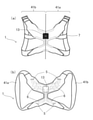
図1は、本発明に係る身体装着具1の装着状態を示す模式図である。図1に示した点線は、人の輪郭を示しており、図1の(a)は、装着者を背面から見た図、図1の(b)は、装着者を正面から見た図をそれぞれ示している。図2は、図1に示した身体装着具1の拡大図であり、図2の(a)は身体装着具1の背面図、図2の(b)は身体装着具1の正面図である。なお、図2の(b)では、ベルト7は図示していない。
FIG. 1 is a schematic view showing a wearing state of the
本発明の身体装着具1は、図1の(a)および図2の(a)に示すように、装着者の右腕を通す右側布帛部41aと、装着者の左腕を通す左側布帛部41bと、を有し、前記右側布帛部41aと前記左側布帛部41bは、装着者の背面側において接続されている。
As shown in FIGS. 1 (a) and 2 (a), the body-wearing
上記身体装着具1は、右側布帛部41aと左側布帛部41bのパーツが縫い合わされて接続されていてもよいし、身体装着具1を背面から見たときに、右側布帛部41aと左側布帛部41bが左右対称となるように一つの布帛で構成されていてもよい。
The
上記右側布帛部41aと上記左側布帛部41bは、いずれも環状であり、図1の(b)に示すように、上記右側布帛部41aには装着者の右腕を通すことができ、上記左側布帛部41bには装着者の左腕を通すことができる。即ち、右側布帛部41aは、一方肩部2aと一方腋窩31aを通っており、左側布帛部41bは、他方肩部2bと他方腋窩31bを通っている。このように、装着者の右腕と左腕とを通す形状としているため、身体の特定位置に固定できる。なお、腋窩とは、わきの下を意味する。また、一方腋窩31aは、一方肩部2a側のわきの下であり、他方腋窩31bは、他方肩部2b側のわきの下である。
The right
上記右側布帛部41aおよび上記左側布帛部41bは、図1、図2に示すように、帯状であってもよいし、後述する図3、図4に示すように、右側布帛部41aは右腕の上腕を覆う袖筒部を有し、左側布帛部41bは左腕の上腕を覆う袖筒部を有してもよい。
The right
上記右側布帛部41aおよび上記左側布帛部41bが帯状の場合、帯の幅は特に限定されないが、例えば、20cm以下が好ましく、より好ましくは15cm以下、更に好ましくは10cm以下である。幅の下限は特に限定されないが、幅が狭すぎると身体へ食い込み、装着者に不快感を与えることがあるため、例えば、1.5cm以上が好ましく、より好ましくは2cm以上、更に好ましくは2.5cm以上である。
When the right
上記右側布帛部41aおよび上記左側布帛部41bが帯状の場合は、幅は一定でもよいし、変化させてもよい。例えば、背側の幅は広くし、腹側の幅は狭くしてもよいし、逆でもよい。
When the right
上記右側布帛部41aおよび上記左側布帛部41bが帯状の場合は、図1の(b)に示すように、長さ調節手段12a、12bを設けることが好ましい。長さ調節手段12a、12bを有することにより、身体装着具1のズレを一層防止できるため、きつく締め付けなくても身体の特定位置に固定でき、自然な状態で身体の生体情報を取得、計測できる。
When the right
上記長さ調節手段12a、12bとしては、例えば、バックル、ホック、面ファスナー、ボタン、スナップボタン、コキ(リュックカン、アジャスター)などの係合部材を用いることができ、単独で、或いは2種以上を併用してもよい。これらのなかでも、留め外し易さの観点から、コキまたはバックルが好ましい。上記長さ調節手段12aと12bは異なっていてもよいが、同じであることが好ましい。なお、図1の(b)に示した長さ調節手段12a、12bは、コキである。 As the length adjusting means 12a and 12b, for example, an engaging member such as a buckle, a hook, a hook-and-loop fastener, a button, a snap button, and a koki (backpack can, adjuster) can be used, and may be used alone or in combination of two or more. May be used together. Among these, a koki or a buckle is preferable from the viewpoint of ease of fastening and removal. The length adjusting means 12a and 12b may be different, but are preferably the same. The length adjusting means 12a and 12b shown in FIG. 1 (b) are handjobs.
上記長さ調節手段12a、12bの数は特に限定されず、1つでもよいし、2つ以上でもよい。長さ調節手段12a、12bを複数設け、間に、例えば、長さ調節ベルトを接続することにより、体格の異なる人同士で上記身体装着具を共有できる。 The number of the length adjusting means 12a and 12b is not particularly limited, and may be one or two or more. By providing a plurality of length adjusting means 12a and 12b and connecting, for example, a length adjusting belt between them, the body wearer can be shared among people having different physiques.
上記右側布帛部41aと上記左側布帛部41bは、図1の(b)に示すように、装着者の前面側において1本のベルト7で接続されている。1本のベルト7で上記右側布帛部41aと上記左側布帛部41bとを接続することによって、装着者が動いても身体装着具1がズレにくくなるため、身体の特定位置に固定できる。また、本発明の身体装着具1は、テキスタイル集積型の衣服や、アクセサリ型のベルトのように、きつく締め付けなくても固定できるため、自然な状態で身体の生体情報を取得、計測できる。更に、本発明の身体装着具1は意匠性が改善されており、装着してもブラジャーを付けているようには見えないため、男性も抵抗なく装着可能となる。本発明の身体装着具1は、衣服の下に装着できるため、衣服が湿潤したり、汚れた場合には、衣服を気軽に着替えることができるし、着用者は好みの衣服を着用できる。
As shown in FIG. 1B, the right
上記ベルト7を設ける位置は特に限定されないが、例えば、鎖骨と乳頭との間であってもよいし、乳頭と腹との間であってもよい。
The position where the
上記ベルト7には、図1の(b)に示すように、長さ調節手段12を設けることが好ましい。長さ調節手段12を有することにより、身体装着具1のズレを一層防止できるため、きつく締め付けなくても身体の特定位置に固定でき、自然な状態で身体の生体情報を取得、計測できる。
As shown in FIG. 1B, it is preferable that the
上記長さ調節手段12としては、上記長さ調節手段12a、12bとして例示したものを用いることができる。なお、図1の(b)に示した長さ調節手段12は、コキである。 As the length adjusting means 12, those exemplified as the length adjusting means 12a and 12b can be used. The length adjusting means 12 shown in FIG. 1 (b) is a job.
上記長さ調節手段12の数は特に限定されず、1つでもよいし、2つ以上でもよい。長さ調節手段12を複数設け、間に、例えば、長さ調節ベルトを接続することにより、体格の異なる人同士で上記身体装着具を共有できる。 The number of the length adjusting means 12 is not particularly limited, and may be one or two or more. By providing a plurality of length adjusting means 12 and connecting, for example, a length adjusting belt between them, the body wearing device can be shared among people having different physiques.
上記ベルトの幅は特に限定されないが、例えば、8cm以下が好ましく、より好ましくは5cm以下、更に好ましくは3cm以下である。幅の下限も特に限定されないが、幅が狭すぎると身体へ食い込み、装着者に不快感を与えることがあるため、例えば、1.5cm以上が好ましく、より好ましくは2cm以上、更に好ましくは2.5cm以上である。 The width of the belt is not particularly limited, but is preferably 8 cm or less, more preferably 5 cm or less, still more preferably 3 cm or less. The lower limit of the width is not particularly limited, but if the width is too narrow, it may bite into the body and cause discomfort to the wearer. Therefore, for example, 1.5 cm or more is preferable, 2 cm or more is more preferable, and 2. It is 5 cm or more.
上記右側布帛部41aと上記左側布帛部41bとの境界付近には、図2の(a)に示したように、電子ユニット13を設けることが好ましい。電子ユニット13は、装着者の肌に接触しない側に設けることが好ましい。一方、装着者の肌に接触する側には、例えば、図2の(b)に示したように、複数の電極5を設け、電極5と電子ユニット13は、電気配線6で接続すればよい。電子ユニット13、電極5、および電気配線6については、後で説明する。
As shown in FIG. 2A, it is preferable to provide an
次に、本発明に係る身体装着具1の他の構成例について、図3および図4を用いて説明する。なお、上記図1、図2と同じ箇所には同一の符号を付すことにより重複説明を避ける。
Next, another configuration example of the
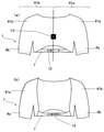
図3は、本発明に係る他の身体装着具1の装着状態を示す模式図である。図3に示した点線は、人の輪郭を示しており、図3の(a)は、装着者を背面から見た図、図3の(b)は、装着者を正面から見た図をそれぞれ示している。図4は、図3に示した身体装着具1の拡大図であり、図4の(a)は身体装着具1の背面図、図4の(b)は身体装着具1の正面図である。
FIG. 3 is a schematic view showing a wearing state of another
図3、図4に示した本発明に係る他の身体装着具1は、上記図1、図2に示した身体装着具1と同様、装着者の右腕を通す右側布帛部41aと、装着者の左腕を通す左側布帛部41bと、を有し、前記右側布帛部41aと前記左側布帛部41bは、装着者の背面側において接続されている点で同じである。
The
図3、図4に示した身体装着具1は、上記図1、図2に示した身体装着具1と異なり、上記右側布帛部41aは右腕の上腕を覆う袖筒部4aを有し、上記左側布帛部41bは左腕の上腕を覆う袖筒部4bを有している。袖筒部4a、4bにそれぞれ腕を通すことにより、身体装着具1を身体の特定位置に固定できる。特に、図3、図4に示した身体装着具1は、身体と接触する面積が広いため、きつく締め付けなくても固定できるため、自然な状態で身体の生体情報を取得、計測できる。更に、本発明の身体装着具1は意匠性が改善されており、装着してもブラジャーを付けているようには見えないため、男性も抵抗なく装着可能となる。本発明の身体装着具1は、衣服の下に装着できるため、衣服が湿潤したり、汚れた場合には、衣服を気軽に着替えることができるし、着用者は好みの衣服を着用できる。
The body fitting 1 shown in FIGS. 3 and 4 is different from the body fitting 1 shown in FIGS. 1 and 2, and the
上記右側布帛部41aが上記袖筒部4aを有する場合は、上記右側布帛部41aのうち胴体を覆う部分と袖筒部4aとの縫い目をなくして一体成形してもよいし、胴体を覆う部分と袖筒部4bとを別パーツとして準備し、縫い合わせて接続してもよい。一体成形することが好ましく、身体への負担を軽減できる。上記左側布帛部41bが上記袖筒部4bを有する場合についても同様である。
When the right
上記袖筒部4a、4bの長さは特に限定されず、一方肩部2a側の上腕および他方肩部2b側の上腕を少なくとも覆うことが好ましく、上腕および前腕(即ち、上肢)を覆ってもよい。
The lengths of the
上記袖筒部4a、4bの袖口には、例えば、装着者の肌に接触する側に滑り止めを設けることが好ましい。滑り止めとしては、袖口と装着者の肌との摩擦力を大きくするために、例えば、シリコーンやゴムなどを袖口に設けることが好ましい。
It is preferable that the cuffs of the
図3、図4に示した身体装着具1の着丈は特に限定されないが、ウエストラインより短いボレロ形状であることが好ましく、一方腋窩31aと他方腋窩31bとを結ぶラインまでの着丈であってもよい。
The length of the body fitting 1 shown in FIGS. 3 and 4 is not particularly limited, but it is preferably a bolero shape shorter than the waistline, and even if the length is up to the line connecting the
上記右側布帛部41aと上記左側布帛部41bは、図3の(b)および図4の(b)に示すように、装着者の前面側において1本のベルト7で接続されている。
The right
上記ベルト7を設ける位置は着丈に応じて調整すればよく、特に限定されないが、例えば、鎖骨と乳頭との間であってもよいし、乳頭と腹との間であってもよい。
The position where the
上記ベルト7には、図3の(b)および図4の(b)に示すように、長さ調節手段12を設けることが好ましい。上記長さ調節手段12としては、上記長さ調節手段12a、12bとして例示したものを用いることができる。なお、図3の(b)および図4の(b)に示した長さ調節手段12は、コキである。
It is preferable that the
上記長さ調節手段12の数は特に限定されず、1つでもよいし、2つ以上でもよい。長さ調節手段12を複数設け、間に、例えば、長さ調節ベルトを接続することにより、体格の異なる人同士で上記身体装着具を共有できる。 The number of the length adjusting means 12 is not particularly limited, and may be one or two or more. By providing a plurality of length adjusting means 12 and connecting, for example, a length adjusting belt between them, the body wearing device can be shared among people having different physiques.
上記ベルト7の幅は特に限定されないが、例えば、8cm以下が好ましく、より好ましくは5cm以下、更に好ましくは3cm以下である。幅の下限も特に限定されないが、幅が狭すぎると身体へ食い込み、装着者に不快感を与えることがあるため、例えば、1.5cm以上が好ましく、より好ましくは2cm以上、更に好ましくは2.5cm以上である。
The width of the
上記右側布帛部41aと上記左側布帛部41bとの境界付近には、図4の(a)に示したように、電子ユニット13を設けることが好ましい。電子ユニット13は、装着者の肌に接触しない側に設けることが好ましい。一方、装着者の肌に接触する側には、例えば、複数の電極5を設け、電極5と電子ユニット13は、電気配線6で接続すればよい(図示せず)。電子ユニット13、電極5、および電気配線6については、後で説明する。
As shown in FIG. 4A, it is preferable to provide an
図1~図4に示した上記身体装着具1の身体への密着圧力は、例えば、0.5kPa以上が好ましい。密着圧力は、より好ましくは0.6kPa以上、更に好ましくは0.8kPa以上である。上限は、例えば、1.2kPa以下が好ましい。上記密着圧力は、例えば、歪みゲージ、ウォーターバック型圧力センサ、エアパック式圧力センサ等を用いて測定できる。
The contact pressure of the body-worn
図1~図4に示した上記身体装着具1には、例えば、上記右側布帛部41aや上記左側布帛部41bに、小物収容部を設けることが好ましい。小物収容部を設けることにより、例えば、スマートフォンや携帯電話、財布、鍵などの小物を入れることができる。
In the
上記小物収容部としては、小物を出し入れするための開口部と、小物を収容し、保持するための保持部を有していればよく、具体的には、ポケット、網状の小物ホルダーなどを設ければよい。 The accessory accommodating portion may have an opening for taking in and out the accessory and a holding portion for accommodating and holding the accessory. Specifically, a pocket, a net-like accessory holder, and the like are provided. Just do it.
上記小物収容部の素材は特に限定されないが、例えば、通気性を高めるためにメッシュ素材で構成してもよいし、収容物を濡らさないように、耐水性を有する素材で構成してもよい。 The material of the accessory accommodating portion is not particularly limited, but for example, it may be composed of a mesh material in order to improve air permeability, or may be composed of a water resistant material so as not to wet the contained object.
上記小物収容部は、装着者の肌に接触しない側に設けてもよいし、装着者の肌に接触する側に設けてもよい。 The accessory accommodating portion may be provided on the side that does not come into contact with the wearer's skin, or may be provided on the side that comes into contact with the wearer's skin.
上記右側布帛部41a、上記左側布帛部41b、上記袖筒部4a、4b、ベルト7を構成する布帛としては、織物、編み物、不織布を例示できる。
Examples of the cloth constituting the right
上記布帛が織物の場合は、例えば、平織、綾織、朱子織等で織られたものを用いることができる。 When the cloth is a woven fabric, for example, a plain weave, a twill weave, a satin weave, or the like can be used.
上記布帛が編み物の場合は、例えば、平編、鹿の子編、アムンゼン編、レース編、アイレット編、添え糸編、パイル編、リブ編、リップル編、亀甲編、ブリスター編、ミラノリブ編、シングルピケ編、ダブルピケ編、斜文編、ヘリボーン編、ポンチローマ編、バスケット編、トリコット編、ハーフトリコット編、サテントリコット編、ダブルトリコット編、クインズコード編、ストライプサッカー編、ラッセル編、チュールメッシュ編、およびこれらを変形・組み合わせて編まれたものを用いることができる。 If the above fabric is knitted, for example, flat knit, Kanoko knit, Amunzen knit, lace knit, eyelet knit, splicing thread knit, pile knit, rib knit, ripple knit, turtle shell knit, blister knit, Milan rib knit, single picket knit. , Double picket, Weave, Heliborn, Ponchi Roma, Basket, Tricot, Half tricot, Satin tricot, Double tricot, Quinn's cord, Striped soccer, Russell, Tulle mesh, and these Can be used by transforming and combining the above.
上記不織布としては、例えば、エラストマー繊維などを用いたものが挙げられる。 Examples of the non-woven fabric include those using elastomer fibers and the like.
上記布帛の素材となる繊維の種類は特に限定されず、天然繊維または化学繊維を用いることができる。上記天然繊維としては、例えば、綿や麻などの植物繊維、羊毛、絹、カシミヤなどの動物繊維などを用いることができる。上記化学繊維としては、例えば、ナイロン、アクリル、ポリエステル、ポリウレタンなどを用いることができる。 The type of fiber used as the material of the cloth is not particularly limited, and natural fiber or chemical fiber can be used. As the natural fiber, for example, plant fiber such as cotton and linen, animal fiber such as wool, silk and cashmere can be used. As the chemical fiber, for example, nylon, acrylic, polyester, polyurethane or the like can be used.
上記繊維は、それぞれ単独で、または混紡して用いることができる。 The fibers can be used alone or in combination.
上記繊維を混紡する場合は、天然繊維と化学繊維を混紡してもよいし、複数種類の天然繊維を混紡してもよいし、複数種類の化学繊維を混紡してもよい。 When the above fibers are blended, natural fibers and chemical fibers may be blended, a plurality of types of natural fibers may be blended, or a plurality of types of chemical fibers may be blended.
混紡する場合の組み合わせとしては、例えば、綿とポリウレタンの組み合わせや、綿、ポリエステル、およびポリウレタンの組み合わせが挙げられる。 Examples of the combination in the case of blending include a combination of cotton and polyurethane, and a combination of cotton, polyester, and polyurethane.
上記布帛が綿を含む場合は、布帛全体の質量を100%としたとき、綿を25質量%以上含有することが好ましい。上記綿の含有量は、より好ましくは45質量%以上、更に好ましくは65質量%以上である。上限は特に限定されず、綿100質量%であってもよいが、より好ましくは95質量%以下である。 When the cloth contains cotton, it is preferable that the cloth contains 25% by mass or more when the total mass of the cloth is 100%. The content of the cotton is more preferably 45% by mass or more, still more preferably 65% by mass or more. The upper limit is not particularly limited and may be 100% by mass of cotton, but more preferably 95% by mass or less.
上記布帛は、綿以外に、更に伸縮性を有する素材を含むことが好ましい。上記伸縮性を有する素材としては、例えば、ポリエステル、ポリウレタン、天然ゴム、合成ゴム、各種エラストマー等からなるスパンデックスなどが挙げられる。 In addition to cotton, the cloth preferably contains a material having further elasticity. Examples of the stretchable material include spandex made of polyester, polyurethane, natural rubber, synthetic rubber, various elastomers and the like.
上記伸縮性を有する素材は、布帛全体の質量を100%としたとき、5質量%以上含有することが好ましい。上記伸縮性を有する素材は、より好ましくは10質量%以上、更に好ましくは15質量%以上である。上限は特に限定されないが、例えば、55質量%以下が好ましい。 The stretchable material preferably contains 5% by mass or more when the total mass of the fabric is 100%. The stretchable material is more preferably 10% by mass or more, still more preferably 15% by mass or more. The upper limit is not particularly limited, but is preferably 55% by mass or less, for example.
上記布帛は、繰り返し10%以上の伸縮が可能な伸縮性を有することが好ましい。伸縮性は、例えば、JIS L1096(2010)における伸縮織物及び編物の伸縮性試験を繰り返し行う事で測定できる。 It is preferable that the fabric has elasticity capable of repeatedly expanding and contracting by 10% or more. The elasticity can be measured, for example, by repeatedly performing the elasticity test of the elastic woven fabric and the knitted fabric in JIS L1096 (2010).
また、上記布帛は、50%以上の破断伸度(引張伸び)を有することが好ましい。破断伸度は、引張強度試験によって測定できる。 Further, the fabric preferably has a breaking elongation (tensile elongation) of 50% or more. The elongation at break can be measured by a tensile strength test.
上記布帛には、樹脂を被覆したり、樹脂を含浸させてもよい。上記布帛に被覆したり、含浸させる樹脂としては、例えば、ポリウレタン、合成ゴム、天然ゴムなどを用いることができる。 The cloth may be coated with a resin or impregnated with the resin. As the resin to be coated or impregnated with the cloth, for example, polyurethane, synthetic rubber, natural rubber or the like can be used.
また、上記布帛の一部に、ゴムシートを用いてもよい。ゴムシートとしては、例えば、クロロプレンに代表される合成ゴムシートの発泡体を用いることができる。合成ゴムシートは、ネオプレン(登録商標)として販売されているものを用いることができる。 Moreover, you may use a rubber sheet as a part of the said cloth. As the rubber sheet, for example, a foam of a synthetic rubber sheet typified by chloroprene can be used. As the synthetic rubber sheet, one sold as neoprene (registered trademark) can be used.
上記右側布帛部41aを構成する布帛と、上記左側布帛部41bを構成する布帛の素材は異なっていてもよいが、同じであることが好ましい。
The materials of the fabric constituting the right
上記右側布帛部41aが上記袖筒部4aを有する場合は、上記右側布帛部41aのうち胴体を覆う部分の布帛と、上記袖筒部4aを構成する布帛の素材は異なっていてもよいが、同じであることが好ましい。上記右側布帛部41bが上記袖筒部4bを有する場合も同様である。
When the right
上記右側布帛部41aおよび上記左側布帛部41bを構成する布帛の素材と、上記ベルトを構成する布帛の素材は同じであってもよいし、異なっていてもよい。
The material of the cloth constituting the right
次に、電子ユニット13、電極5、および電気配線6について説明する。上記身体装着具1は、装着者の肌に接触する複数の電極を有しており、上記電極では、電気信号を取得する。
Next, the
上記身体装着具1は、(a)装着者の腹側に一対の電極を少なくとも一組有してもよいし、(b)装着者の背側に一対の電極を少なくとも一組有してもよいし、(c)装着者の右外側と左外側で一対となる電極を少なくとも一組有してもよいし、(d)装着者の腹側と背側で一対となる電極を少なくとも一組有してもよい。上記(d)の場合は、装着者の腹側には、鎖骨と乳頭の間に一方電極を有し、装着者の背側には、前記一方電極より身長方向の下方に他方電極を有してもよい。上記電極は、一組でもよいし、二組以上設けてもよい。
The
上記電極の形状や大きさは特に限定されず、上記身体装着具1の形状や大きさを考慮して定めればよい。
The shape and size of the electrodes are not particularly limited, and may be determined in consideration of the shape and size of the
上記電極としては、例えば、(1)金属箔、(2)導電性ファブリック、(3)伸縮性導体層などを形成すればよい。 As the electrode, for example, (1) a metal foil, (2) a conductive fabric, (3) an elastic conductor layer, or the like may be formed.
(1)金属箔
上記金属箔としては、例えば、銅箔、りん青銅箔、ニッケルメッキ銅箔、錫メッキ銅箔、ニッケル/金メッキ銅箔、アルミニウム箔、銀箔、および金箔よりなる群から選択される少なくとも一種の金属箔が好ましい。
(1) Metal Foil The metal foil is selected from the group consisting of, for example, copper foil, phosphorus bronze foil, nickel-plated copper foil, tin-plated copper foil, nickel / gold-plated copper foil, aluminum foil, silver foil, and gold foil. At least one type of metal leaf is preferred.
上記金属箔の平均厚さは、例えば、0.08μm以上が好ましい。また、平均厚さは、50μm以下が好ましく、より好ましくは25μm以下、更に好ましくは15μm以下、特に好ましくは8μm以下、最も好ましくは4μm以下である。 The average thickness of the metal foil is preferably 0.08 μm or more, for example. The average thickness is preferably 50 μm or less, more preferably 25 μm or less, still more preferably 15 μm or less, particularly preferably 8 μm or less, and most preferably 4 μm or less.
上記金属箔は、例えば、電解法、無電解法、圧延法、蒸着法、スパッタリング法など公知の方法で形成すればよい。 The metal foil may be formed by a known method such as an electrolytic method, a non-electrolytic method, a rolling method, a vapor deposition method, or a sputtering method.
また、上記金属箔は、例えば、エッチング法、リフトオフ法、アディティブ法、打ち抜き法、レーザーカッティング法などの方法により、所定のパターン形状に加工することが好ましい。 Further, the metal leaf is preferably processed into a predetermined pattern shape by, for example, an etching method, a lift-off method, an additive method, a punching method, a laser cutting method, or the like.
(2)導電性ファブリック
上記導電性ファブリックとは、導電性を有する繊維構造体を意味する。上記導電性ファブリックとしては、例えば、導電糸(導電性糸、導電性繊維を含む意味。以下、同じ。)を含む繊維で構成された織物、編み物、不織布が挙げられる。上記導電糸とは、繊維長1cmあたりの抵抗値が100Ω以下の糸を意味する。
(2) Conductive fabric The conductive fabric means a fiber structure having conductivity. Examples of the conductive fabric include textiles, knitting fabrics, and non-woven fabrics made of fibers containing conductive yarns (meaning including conductive yarns and conductive fibers; the same applies hereinafter). The conductive yarn means a yarn having a resistance value of 100 Ω or less per 1 cm of fiber length.
上記導電糸とは、導電性繊維、導電性繊維の繊維束、導電性繊維を含む繊維から得られる撚糸、組み糸、紡績糸、混紡糸、金属線を極細に延伸した極細金属線、フィルムを極細の繊維状に切断した極細フィルムの総称である。 The conductive yarns include conductive fibers, fiber bundles of conductive fibers, twisted yarns obtained from fibers containing conductive fibers, braided yarns, spun yarns, blended yarns, ultrafine metal wires obtained by finely stretching metal wires, and films. It is a general term for ultra-fine films cut into ultra-fine fibers.
上記導電性繊維としては、例えば、金属で被覆された化学繊維または天然繊維、導電性金属酸化物で被覆された化学繊維または天然繊維、グラファイト、カーボン、カーボンナノチューブ、グラフェンなどのカーボン系導電性材料で被覆された化学繊維または天然繊維、導電性高分子で被覆された化学繊維または天然繊維などが挙げられる。 Examples of the conductive fiber include a chemical fiber or a natural fiber coated with a metal, a chemical fiber or a natural fiber coated with a conductive metal oxide, and a carbon-based conductive material such as graphite, carbon, carbon nanotube, and graphene. Examples thereof include chemical fibers or natural fibers coated with a conductive polymer, chemical fibers or natural fibers coated with a conductive polymer, and the like.
また、上記導電性繊維として、例えば、金属、導電性金属酸化物、カーボン系導電性材料、および導電性高分子よりなる群から選ばれる少なくとも1種の導電性材料を含む高分子材料を紡糸して得られた繊維を用いることができる。 Further, as the conductive fiber, a polymer material containing at least one conductive material selected from the group consisting of, for example, a metal, a conductive metal oxide, a carbon-based conductive material, and a conductive polymer is spun. The obtained fiber can be used.
上記導電性繊維の繊維束としては、例えば、上記導電性繊維のマイクロファイバーやナノファイバーなどからなる繊維束に、導電性フィラーや導電性高分子等を担持、含浸させて得られたものを用いることができる。 As the fiber bundle of the conductive fiber, for example, a fiber bundle made of microfibers or nanofibers of the conductive fiber is impregnated with a conductive filler or a conductive polymer and is used. be able to.
上記導電糸として、上記導電性繊維を含む繊維を用いて得られた撚糸、組み糸、紡績糸、混紡糸など用いてもよい。 As the conductive yarn, twisted yarn, braided yarn, spun yarn, blended yarn or the like obtained by using the fiber containing the conductive fiber may be used.
上記導電糸には、金属線を極細に延伸した極細金属線も包含される。 The conductive thread also includes an extra-fine metal wire obtained by drawing an ultra-fine metal wire.
上記導電性繊維、上記導電性繊維の繊維束、上記導電性繊維を含む繊維から得られる撚糸、組み糸、紡績糸、混紡糸、上記極細金属線の平均直径は、250μm以下が好ましく、より好ましくは120μm以下、更に好ましくは80μm以下、特に好ましくは50μm以下である。 The average diameter of the conductive fiber, the fiber bundle of the conductive fiber, the twisted yarn, the braided yarn, the spun yarn, the blended yarn obtained from the fiber containing the conductive fiber, and the ultrafine metal wire is preferably 250 μm or less, more preferably. Is 120 μm or less, more preferably 80 μm or less, and particularly preferably 50 μm or less.
上記導電糸には、フィルムを極細の繊維状に切断した極細フィルムも包含され、上記極細フィルムとは、金属、導電性金属酸化物、カーボン系導電性材料、および導電性高分子よりなる群から選ばれる少なくとも1種の導電性材料を被覆した高分子フィルムを幅800μm以下に切断して得られた繊維状フィルムを意味する。 The conductive thread also includes an ultrafine film obtained by cutting a film into ultrafine fibers, and the ultrafine film is composed of a group consisting of a metal, a conductive metal oxide, a carbon-based conductive material, and a conductive polymer. It means a fibrous film obtained by cutting a polymer film coated with at least one selected conductive material to a width of 800 μm or less.
上記導電糸のなかでも、金属で被覆された化学繊維、導電性高分子を担持、含浸させた導電性繊維の繊維束、および平均直径が50μm以下の極細金属線よりなる群から選ばれる少なくとも1種を用いることが好ましい。 Among the above conductive threads, at least one selected from the group consisting of metal-coated chemical fibers, fiber bundles of conductive fibers carrying and impregnating a conductive polymer, and ultrafine metal wires having an average diameter of 50 μm or less. It is preferable to use seeds.
上記導電性ファブリックとしては、具体的には、非導電性の布帛に導電糸を刺繍した繊維構造体、非導電性の布帛に導電性高分子含有溶液を含浸、乾燥させた繊維構造体、導電性フィラーとバインダー樹脂とを含む溶液を含浸、乾燥させた繊維構造体などが挙げられる。これらのなかでも、非導電性の布帛に導電性高分子含有溶液を含浸、乾燥させた繊維構造体を用いることが好ましい。 Specific examples of the conductive fabric include a fiber structure in which a conductive thread is embroidered on a non-conductive cloth, a fiber structure in which a non-conductive cloth is impregnated with a conductive polymer-containing solution and dried, and a conductive fabric. Examples thereof include a fiber structure impregnated with a solution containing a sex filler and a binder resin and dried. Among these, it is preferable to use a fiber structure in which a non-conductive fabric is impregnated with a conductive polymer-containing solution and dried.
上記導電性高分子としては、例えば、ポリ(3,4-エチレンジオキシチオフェン)とポリスチレンスルホン酸とを含む混合物を好ましく用いることができる。 As the conductive polymer, for example, a mixture containing poly (3,4-ethylenedioxythiophene) and polystyrene sulfonic acid can be preferably used.
上記導電糸を含む繊維としては、合成繊維マルチフィラメントが好ましく、該合成繊維マルチフィラメントの少なくとも一部が、繊度が30dtex未満の極細フィラメントであるか、或いは、繊度が400dtexを超え、かつ単糸繊度が0.2dtex以下の合成繊維マルチフィラメントであることが好ましい。 As the fiber containing the conductive yarn, a synthetic fiber multifilament is preferable, and at least a part of the synthetic fiber multifilament is an ultrafine filament having a fineness of less than 30 dtex, or a fineness of more than 400 dtex and a single yarn fineness. It is preferable that the synthetic fiber multifilament has a value of 0.2 dtex or less.
上記導電性ファブリックが、導電糸を含む繊維で構成された織物であるか、編み物である場合は、目付けは50g/m2未満が好ましく、導電性高分子の脱落を防止できる。また、目付けは300g/m2を超えることが好ましく、充分な導電性を確保できる。 When the conductive fabric is a woven fabric composed of fibers containing conductive threads or is knitted, the texture is preferably less than 50 g / m 2 , and the conductive polymer can be prevented from falling off. Further, the basis weight is preferably more than 300 g / m 2 , and sufficient conductivity can be ensured.
(3)伸縮性導体層
上記伸縮性導体層とは、伸縮性を有し、且つ比抵抗が1×100Ωcm以下の層を意味する。上記伸縮性とは、導電性を保った状態で、繰り返し10%以上の伸縮が可能であることを意味する。
(3) Stretchable Conductor Layer The stretchable conductor layer means a layer having elasticity and having a specific resistance of 1 × 100 Ωcm or less. The above-mentioned elasticity means that expansion and contraction of 10% or more is possible repeatedly while maintaining conductivity.
上記伸縮性導体層は、層単独で40%以上の破断伸度を有することが好ましい。破断伸度は、より好ましくは50%以上、更に好ましくは80%以上である。破断伸度は、導電性ペーストを離型シート上に所定の膜厚に塗布し、乾燥後に剥離し、引張試験を行って測定できる。 The stretchable conductor layer is preferably a single layer having a breaking elongation of 40% or more. The elongation at break is more preferably 50% or more, still more preferably 80% or more. The elongation at break can be measured by applying a conductive paste on a release sheet to a predetermined film thickness, drying it, peeling it off, and performing a tensile test.
上記伸縮性導体層は、引張弾性率が10~500MPaであることが好ましい。 The elastic conductor layer preferably has a tensile elastic modulus of 10 to 500 MPa.
上記伸縮性導体層の平均厚さは、例えば、15μm以上が好ましく、より好ましくは30μm以上である。平均厚さは、例えば、250μm以下が好ましく、より好ましくは150μm以下、更に好ましくは80μm以下である。 The average thickness of the stretchable conductor layer is, for example, preferably 15 μm or more, and more preferably 30 μm or more. The average thickness is, for example, preferably 250 μm or less, more preferably 150 μm or less, still more preferably 80 μm or less.
このような伸縮性導体層を形成できる材料を、以下、伸縮性導体層用組成物と呼ぶことがある。 A material capable of forming such an elastic conductor layer may be hereinafter referred to as a composition for an elastic conductor layer.
上記伸縮性導体層は、例えば、伸縮性導体層用組成物として導電性ペーストを用いて形成できる。 The stretchable conductor layer can be formed, for example, by using a conductive paste as a composition for a stretchable conductor layer.
導電性ペーストは、少なくとも(i)導電性粒子、(ii)柔軟性樹脂、および(iii)溶剤を含むものである。 The conductive paste contains at least (i) conductive particles, (ii) a flexible resin, and (iii) a solvent.
(i)導電性粒子
上記導電性粒子とは、比抵抗が1×10⁻¹Ωcm以下の粒子を意味する。上記比抵抗が1×10⁻¹Ωcm以下の粒子としては、例えば、金属粒子、合金粒子、カーボン粒子、カーボンナノチューブ粒子、ドーピングされた半導体粒子、導電性高分子粒子、ハイブリッド粒子などが挙げられる。
(I) Conductive particles The conductive particles mean particles having a specific resistance of 1 × 10 -1 Ωcm or less. Examples of the particles having a specific resistance of 1 × 10 -1 Ωcm or less include metal particles, alloy particles, carbon particles, carbon nanotube particles, doped semiconductor particles, conductive polymer particles, hybrid particles and the like.
上記金属粒子としては、例えば、銀粒子、金粒子、白金粒子、パラジウム粒子、銅粒子、ニッケル粒子、アルミニウム粒子、亜鉛粒子、鉛粒子、錫粒子などが挙げられる。上記合金粒子としては、例えば、黄銅粒子、青銅粒子、白銅粒子、半田粒子などが挙げられる。上記ドーピングされた半導体粒子としては、例えば、錫の酸化物、インジウムと錫の複合酸化物などが挙げられる。上記導電性高分子粒子としては、例えば、ポリ(3,4-エチレンジオキシチオフェン)とポリスチレンスルホン酸とを含む混合物からなる粒子や、金属被覆した高分子粒子が挙げられる。上記ハイブリッド粒子としては、例えば、金属被覆した金属粒子、金属被覆したガラス粒子、金属被覆したセラミック粒子などが挙げられる。上記金属被覆した金属粒子としては、例えば、銀被覆銅粒子が挙げられる。 Examples of the metal particles include silver particles, gold particles, platinum particles, palladium particles, copper particles, nickel particles, aluminum particles, zinc particles, lead particles, tin particles and the like. Examples of the alloy particles include brass particles, bronze particles, cupronickel particles, solder particles and the like. Examples of the doped semiconductor particles include an oxide of tin and a composite oxide of indium and tin. Examples of the conductive polymer particles include particles composed of a mixture containing poly (3,4-ethylenedioxythiophene) and polystyrene sulfonic acid, and metal-coated polymer particles. Examples of the hybrid particles include metal-coated metal particles, metal-coated glass particles, and metal-coated ceramic particles. Examples of the metal-coated metal particles include silver-coated copper particles.
上記導電性粒子の平均粒子径は、例えば、100μm以下が好ましく、より好ましくは30μm以下、更に好ましくは12μm以下である。上記平均粒子径の下限は特に限定されないが、例えば、0.08μm以上である。 The average particle size of the conductive particles is, for example, preferably 100 μm or less, more preferably 30 μm or less, still more preferably 12 μm or less. The lower limit of the average particle size is not particularly limited, but is, for example, 0.08 μm or more.
上記粒子は、例えば、フレーク状粉であってもよいし、不定形凝集粉であってもよい。例えば、上記銀粒子としては、フレーク状銀粒子や不定形凝集銀粉を用いることができる。 The particles may be, for example, flake-like powder or amorphous agglomerated powder. For example, as the silver particles, flake-shaped silver particles or amorphous aggregated silver powder can be used.
上記フレーク状粉の平均粒子径は、動的光散乱法により測定した平均粒子径(50%D)が、例えば、0.5~20μmであるものが好ましい。平均粒子径が0.5μm未満では、粒子同士が接触できないことがあり、導電性が悪化するおそれがある。平均粒子径は、より好ましくは3μm以上、更に好ましくは5μm以上である。しかし、平均粒子径が20μmを超えると、微細な配線の形成が困難になることがある。また、スクリーン印刷などを行うと、目詰まりすることがある。平均粒子径は、より好ましくは15μm以下、更に好ましくは12μm以下である。 The average particle size of the flake-like powder is preferably such that the average particle size (50% D) measured by the dynamic light scattering method is, for example, 0.5 to 20 μm. If the average particle size is less than 0.5 μm, the particles may not come into contact with each other, and the conductivity may deteriorate. The average particle size is more preferably 3 μm or more, still more preferably 5 μm or more. However, if the average particle size exceeds 20 μm, it may be difficult to form fine wiring. In addition, screen printing or the like may cause clogging. The average particle size is more preferably 15 μm or less, still more preferably 12 μm or less.
上記不定形凝集粉の平均粒子径は、光錯乱法により測定した平均粒子径(50%D)が、例えば、1~20μmであるものが好ましい。平均粒子径が1μm未満では、凝集粉としての効果が失われ、導電性を維持できないことがある。平均粒子径は、より好ましくは3μm以上、更に好ましくは5μm以上である。しかし、平均粒子径が20μmを超えると、溶剤への分散性が低下し、ペースト化が難しくなる。平均粒子径は、より好ましくは15μm以下、更に好ましくは12μm以下である。 The average particle size of the amorphous agglomerated powder is preferably 1 to 20 μm, for example, the average particle size (50% D) measured by the optical confusion method. If the average particle size is less than 1 μm, the effect as agglomerated powder may be lost and the conductivity may not be maintained. The average particle size is more preferably 3 μm or more, still more preferably 5 μm or more. However, if the average particle size exceeds 20 μm, the dispersibility in the solvent is lowered and it becomes difficult to make a paste. The average particle size is more preferably 15 μm or less, still more preferably 12 μm or less.
(ii)柔軟性樹脂
上記柔軟性樹脂とは、弾性率が1~1000MPaの熱可塑性樹脂、熱硬化性樹脂、ゴムなどを用いることができる。膜の伸縮性を発現させるために、ゴムを用いることが好ましい。上記弾性率は、好ましくは3MPa以上、より好ましくは10MPa以上、更に好ましくは30MPa以上である。上記弾性率は、好ましくは600MPa以下、より好ましく500MPa以下、更に好ましくは300MPa以下である。
(Ii) Flexible Resin As the flexible resin, a thermoplastic resin having an elastic modulus of 1 to 1000 MPa, a thermosetting resin, rubber, or the like can be used. It is preferable to use rubber in order to develop the elasticity of the film. The elastic modulus is preferably 3 MPa or more, more preferably 10 MPa or more, still more preferably 30 MPa or more. The elastic modulus is preferably 600 MPa or less, more preferably 500 MPa or less, still more preferably 300 MPa or less.
上記熱可塑性樹脂としては、例えば、ポリエチレン、ポリ塩化ビニル、ポリスチレン、ポリ酢酸ビニル、ポリウレタン、アクリル樹脂、ポリアミド、ポリエステルなどを用いることができる。上記熱硬化性樹脂としては、例えば、フェノール樹脂、エポキシ樹脂、メラミン樹脂、シリコーン樹脂などを用いることができる。 As the thermoplastic resin, for example, polyethylene, polyvinyl chloride, polystyrene, polyvinyl acetate, polyurethane, acrylic resin, polyamide, polyester and the like can be used. As the thermosetting resin, for example, a phenol resin, an epoxy resin, a melamine resin, a silicone resin, or the like can be used.
上記ゴムとしては、例えば、ウレタンゴム、アクリルゴム、シリコーンゴム、ブタジエンゴム、ニトリルゴムや水素化ニトリルゴムなどのニトリル基含有ゴム、イソプレンゴム、硫化ゴム、スチレンブタジエンゴム、ブチルゴム、クロロプレンゴム、クロロスルホン化ポリエチレンゴム、エチレンプロピレンゴム、フッ化ビニリデンコポリマーなどが挙げられる。これらの中でも、ニトリル基含有ゴム、クロロプレンゴム、クロロスルホン化ポリエチレンゴムが好ましく、ニトリル基含有ゴムが特に好ましい。 Examples of the rubber include urethane rubber, acrylic rubber, silicone rubber, butadiene rubber, nitrile group-containing rubber such as nitrile rubber and hydride nitrile rubber, isoprene rubber, sulfide rubber, styrene butadiene rubber, butyl rubber, chloroprene rubber, and chlorosulfone. Examples thereof include styrene rubber, ethylene propylene rubber, and vinylidene fluoride copolymer. Among these, nitrile group-containing rubber, chloroprene rubber, and chlorosulfonated polyethylene rubber are preferable, and nitrile group-containing rubber is particularly preferable.
上記ニトリル基含有ゴムは、ニトリル基を含有するゴムやエラストマーであれば特に限定されず、例えば、ニトリルゴムと水素化ニトリルゴムが好ましい。ニトリルゴムはブタジエンとアクリロニトリルの共重合体であり、結合アクリロニトリル量が多いと金属との親和性が増加するが、伸縮性に寄与するゴム弾性は逆に減少する。従って、アクリロニトリル-ブタジエン共重合体ゴム中の結合アクリロニトリル量は18~50質量%が好ましく、より好ましくは40~50質量%である。 The nitrile group-containing rubber is not particularly limited as long as it is a nitrile group-containing rubber or elastomer, and for example, nitrile rubber and hydrogenated nitrile rubber are preferable. Nitrile rubber is a copolymer of butadiene and acrylonitrile, and when the amount of bound acrylonitrile is large, the affinity with the metal increases, but the rubber elasticity that contributes to elasticity decreases. Therefore, the amount of bonded acrylonitrile in the acrylonitrile-butadiene copolymer rubber is preferably 18 to 50% by mass, more preferably 40 to 50% by mass.
上記柔軟性樹脂の配合量は、導電性粒子と柔軟性樹脂の合計に対して、7~35質量%であり、より好ましくは9質量%以上、更に好ましくは12質量%以上、より好ましくは28質量%以下、更に好ましくは20質量%以下である。 The blending amount of the flexible resin is 7 to 35% by mass, more preferably 9% by mass or more, still more preferably 12% by mass or more, and more preferably 28 with respect to the total of the conductive particles and the flexible resin. It is 0% by mass or less, more preferably 20% by mass or less.
(iii)溶剤
上記溶剤は特に限定されず、公知の有機溶媒または水系溶媒を用いることができる。
(Iii) Solvent The solvent is not particularly limited, and a known organic solvent or aqueous solvent can be used.
上記電極の表面、即ち、装着者の肌に接触する側には、電極表面層を有することが好ましい。一方、上記電極と上記布帛部との境界には、絶縁性を高めるために、下地層を有することが好ましい。 It is preferable to have an electrode surface layer on the surface of the electrode, that is, on the side in contact with the wearer's skin. On the other hand, it is preferable to have a base layer at the boundary between the electrode and the cloth portion in order to improve the insulating property.
(電極表面層)
上記電極表面層としては、例えば、貴金属メッキ層、不動態形成により酸化しにくい金属層、耐食性合金層、カーボン層、伸縮性導電層などが挙げられ、単独で、あるいは2種以上を積層して設けてもよい。
(Electrode surface layer)
Examples of the electrode surface layer include a noble metal plating layer, a metal layer that is difficult to oxidize due to passivation formation, a corrosion-resistant alloy layer, a carbon layer, an elastic conductive layer, and the like, and may be used alone or in combination of two or more. It may be provided.
上記貴金属メッキ層としては、例えば、金、銀、白金、ロジウム、およびルテニウムよりなる群から選ばれる少なくとも1種の層が挙げられる。上記不動態形成により酸化しにくい金属層としては、例えば、クロム、モリブデン、タングステン、およびニッケルよりなる群から選ばれる1種の層が挙げられる。上記耐食性合金層としては、例えば、モネル合金などの層が挙げられる。上記カーボン層は、上記電極の表面に、例えば、カーボンペーストなどを印刷して層を形成することが好ましい。上記伸縮性導電層としては、例えば、導電性フィラーと柔軟性樹脂などを含む伸縮性導電組成物を用いて層を形成することが好ましい。 Examples of the noble metal plating layer include at least one layer selected from the group consisting of gold, silver, platinum, rhodium, and ruthenium. Examples of the metal layer that is difficult to oxidize due to the passivation formation include one layer selected from the group consisting of chromium, molybdenum, tungsten, and nickel. Examples of the corrosion-resistant alloy layer include layers such as Monel alloy. It is preferable that the carbon layer is formed by printing, for example, carbon paste on the surface of the electrode. As the stretchable conductive layer, it is preferable to form the layer by using, for example, a stretchable conductive composition containing a conductive filler and a flexible resin.
上記電極表面層の平均厚さは、12μm以上が好ましく、より好ましくは20μm以上、更に好ましくは40μm以上である。上記平均厚さとは、電極表面層の算術平均厚さであり、厚さを無作為に10点測定した値の算術平均値である。 The average thickness of the electrode surface layer is preferably 12 μm or more, more preferably 20 μm or more, and further preferably 40 μm or more. The above-mentioned average thickness is an arithmetic average thickness of the electrode surface layer, and is an arithmetic average value of a value obtained by randomly measuring 10 points of the thickness.
(下地層)
上記絶縁性とは、電気的な絶縁性に加え、機械的、化学的、生物学的な絶縁性を含む意味である。即ち、布帛を透過してくる汗などの水分や、化学物質、生体物質から電極を絶縁する機能を有している。
(Underground layer)
The above-mentioned insulating property means that it includes mechanical, chemical, and biological insulating properties in addition to electrical insulating properties. That is, it has a function of insulating the electrode from moisture such as sweat that permeates the cloth, chemical substances, and biological substances.
上記下地層は、柔軟な高分子材料であることが好ましい。上記柔軟な高分子材料としては、ゴム、エラストマーと呼ばれる材料を用いることができる。上記ゴム、エラストマーとしては、伸縮性導体層用組成物として例示した柔軟性樹脂で具体的に挙げたゴム、エラストマーを好ましく用いることができる。 The base layer is preferably a flexible polymer material. As the flexible polymer material, materials called rubber and elastomer can be used. As the rubber and the elastomer, the rubber and the elastomer specifically mentioned in the flexible resin exemplified as the composition for the elastic conductor layer can be preferably used.
上記下地層の平均厚さは、12μm以上が好ましく、より好ましくは20μm以上、更に好ましくは40μm以上である。上記平均厚さとは、下地層の算術平均厚さであり、厚さを無作為に10点測定した値の算術平均値である。 The average thickness of the base layer is preferably 12 μm or more, more preferably 20 μm or more, and further preferably 40 μm or more. The above-mentioned average thickness is the arithmetic average thickness of the base layer, and is the arithmetic mean value of the value obtained by randomly measuring the thickness at 10 points.
上記下地層は、繰り返し10%以上の伸縮が可能な伸縮性を有することが好ましい。また、上記下地層は、50%以上の破断伸度を有することが好ましい。更に、上記下地層は、引張弾性率が10~500MPaであることが好ましい。 It is preferable that the base layer has elasticity capable of repeatedly expanding and contracting by 10% or more. Further, the underlying layer preferably has a breaking elongation of 50% or more. Further, the underlying layer preferably has a tensile elastic modulus of 10 to 500 MPa.
上記下地層は、布帛の表面に、例えば、コーティング液、浸漬液、印刷インクまたは印刷ペースト等の液状物、スラリー状物を介して形成することが好ましい。 The base layer is preferably formed on the surface of the fabric via, for example, a coating liquid, a dipping liquid, a liquid material such as a printing ink or a printing paste, or a slurry-like material.
また、上記下地層として、予めウレタン樹脂、あるいはゴムなどをシート化したものを準備しておき、ホットプレスなどの手法で布帛と貼り合わせて形成してもよい。 Further, as the base layer, a urethane resin or a sheet made of rubber or the like may be prepared in advance and bonded to the cloth by a method such as hot pressing.
(電子ユニット)
上記身体装着具は、上記電極の他、電極で取得した電気信号を演算する機能(演算手段)を有する電子ユニットを備えていることが好ましい。上記電子ユニットでは、電極で取得した電気信号を演算することにより、例えば、心拍数、脈拍数、呼吸数、血圧、体温、筋電などの身体の生体情報が得られる。
(Electronic unit)
In addition to the electrodes, the body-worn device preferably includes an electronic unit having a function (calculation means) for calculating an electric signal acquired by the electrodes. In the electronic unit, by calculating the electric signal acquired by the electrodes, for example, biological information of the body such as heart rate, pulse rate, respiratory rate, blood pressure, body temperature, and myoelectricity can be obtained.
上記電子ユニットは、更に、表示手段、記憶手段、通信手段、USBコネクタなどを有することが好ましい。 The electronic unit preferably further includes a display means, a storage means, a communication means, a USB connector, and the like.
上記通信手段としては、例えば、ブルートゥース(登録商標)などにより変換された生体情報を、外部機器(例えば、腕時計や、パーソナルコンピューター、タブレット型パーソナルコンピューター、スマートフォンなどの携帯情報機器など)へ無線で送信できる機能を備えることが好ましい。また、電子ユニットにコネクタを設け、電子ユニットと外部機器とを有線で接続し、電子ユニット内に記憶させた生体情報を外部機器へ送信できる機能を備えることも好ましい。 As the above-mentioned communication means, for example, biometric information converted by Bluetooth (registered trademark) or the like is wirelessly transmitted to an external device (for example, a wristwatch, a personal computer, a tablet-type personal computer, a mobile information device such as a smartphone). It is preferable to have a function capable of performing. It is also preferable to provide a connector in the electronic unit, connect the electronic unit and the external device by wire, and have a function of transmitting the biometric information stored in the electronic unit to the external device.
上記電子ユニットは、気温、湿度、気圧などの環境情報を計測できるセンサや、GPSを用いた位置情報を計測できるセンサなどを備えてもよい。 The electronic unit may include a sensor capable of measuring environmental information such as temperature, humidity, and atmospheric pressure, a sensor capable of measuring position information using GPS, and the like.
上記電子ユニットは、身体装着具に対して脱着できることが好ましい。 It is preferable that the electronic unit can be attached to and detached from the body wearer.
(電気配線)
上記電極と上記電子ユニットは、電力供給用や信号伝送用の電気配線で接続されている。
(Electric wiring)
The electrodes and the electronic units are connected by electrical wiring for power supply and signal transmission.
上記電気配線としては、上記電極と同様、例えば、(1)金属箔、(2)導電性ファブリック、(3)伸縮性導体層などを形成すればよい。 As the electrical wiring, for example, (1) a metal foil, (2) a conductive fabric, (3) an elastic conductor layer and the like may be formed in the same manner as the above electrodes.
電気配線の厚みは、電極の厚みと同じであってもよい。 The thickness of the electrical wiring may be the same as the thickness of the electrodes.
上記電気配線として、金属箔を形成する場合は、例えば、ゴムシート、ウレタンシート、シリコーンゴムシートなどの伸縮可能なシートと金属箔との積層体を形成した後、サブトラクティブ法で、金属箔の不要部分を除去し、所定のパターンを形成すればよい。上記サブトラクティブ法とは、一般的なプリント配線板製法に用いられるエッチング法と同義である。 When forming a metal foil as the above electrical wiring, for example, after forming a laminate of a stretchable sheet such as a rubber sheet, a urethane sheet, or a silicone rubber sheet and the metal foil, the metal foil is formed by a subtractive method. The unnecessary portion may be removed to form a predetermined pattern. The subtractive method is synonymous with the etching method used in a general printed wiring board manufacturing method.
上記伸縮可能なシートは、布帛との境界に、下地層を兼ねてもよく、下地層の一部として構成してもよい。 The stretchable sheet may also serve as a base layer at the boundary with the fabric, or may be configured as a part of the base layer.
上記電気配線として、導電性ファブリックを形成する場合は、電気配線を導電糸とし、導電性ファブリックを用いた電極と組み合わせることが好ましい。 When forming a conductive fabric as the electrical wiring, it is preferable to use the electrical wiring as a conductive thread and combine it with an electrode using the conductive fabric.
上記電気配線は、冗長性を有することが好ましい。上記冗長性とは、空間中に、点A、点Bの二点を定義したときに、二点間の最短距離Xに対して、最短距離よりも長い経路Yを用いて2点を結ぶことにより、二点間の距離が伸びた際にも余裕をもって接続状態が維持される状態を意味する。冗長性は、下記式で定義される冗長性係数で評価できる。
冗長性係数=Y/X
The electrical wiring is preferably redundant. The above-mentioned redundancy means that when two points A and B are defined in space, two points are connected by using a path Y longer than the shortest distance with respect to the shortest distance X between the two points. This means that the connected state is maintained with a margin even when the distance between the two points is extended. Redundancy can be evaluated by the redundancy coefficient defined by the following equation.
Redundancy coefficient = Y / X
二点間の距離を測定して冗長性係数を算出するにあたり、線路が幅を有している場合は、線路の中央を通る線の長さを測定すればよい。 When measuring the distance between two points and calculating the redundancy coefficient, if the line has a width, the length of the line passing through the center of the line may be measured.
上記電気配線に冗長性を持たせるには、上記電気配線の形状を、例えば、波形模様やジグザグ模様、馬蹄形が繰り返された模様などにすればよい。例えば、導電性ファブリックの場合は、導電糸をニットに組み込み、導電糸でループを作って冗長性を確保し、ニット生地そのものを電気配線として用いることができる。 In order to give redundancy to the electric wiring, the shape of the electric wiring may be, for example, a corrugated pattern, a zigzag pattern, a pattern in which a horseshoe shape is repeated, or the like. For example, in the case of a conductive fabric, the conductive yarn can be incorporated into the knit, a loop can be formed with the conductive yarn to ensure redundancy, and the knit fabric itself can be used as electrical wiring.
本発明において、上記冗長性係数は1.41以上が好ましく、より好ましくは1.8以上、更に好ましくは2.2以上、特に好ましくは2.8以上である。 In the present invention, the redundancy coefficient is preferably 1.41 or more, more preferably 1.8 or more, still more preferably 2.2 or more, and particularly preferably 2.8 or more.
上記電気配線の表面、即ち、布帛とは反対側には、電気配線表面層を設けることが好ましい。一方、上記電極と同様、上記電気配線と上記布帛部との境界には、絶縁性を高めるために、下地層を設けることが好ましい。 It is preferable to provide an electric wiring surface layer on the surface of the electric wiring, that is, on the side opposite to the cloth. On the other hand, as with the electrodes, it is preferable to provide a base layer at the boundary between the electrical wiring and the cloth portion in order to improve the insulating property.
(電気配線表面層)
上記電気配線表面層としては、絶縁性を有する絶縁皮膜を設けることが好ましい。上記絶縁皮膜の抵抗率は、1×10⁹Ωcm以上が好ましい。
(Electrical wiring surface layer)
As the electrical wiring surface layer, it is preferable to provide an insulating film having an insulating property. The resistivity of the insulating film is preferably 1 × 10 9 Ωcm or more.
上記絶縁皮膜としては、例えば、ポリウレタン、シリコーンゴム、ポリアクリル酸エステルなどからなる絶縁層を設けることが好ましい。 As the insulating film, for example, it is preferable to provide an insulating layer made of polyurethane, silicone rubber, polyacrylic acid ester or the like.
上記電気配線表面層の平均厚さは、12μm以上が好ましく、より好ましくは20μm以上、更に好ましくは40μm以上である。上記平均厚さとは、絶縁皮膜の算術平均厚さであり、厚さを無作為に10点測定した値の算術平均値である。 The average thickness of the electric wiring surface layer is preferably 12 μm or more, more preferably 20 μm or more, and further preferably 40 μm or more. The above-mentioned average thickness is the arithmetic average thickness of the insulating film, and is the arithmetic mean value of the value obtained by randomly measuring the thickness at 10 points.
上記絶縁皮膜は、絶縁性の他、更に伸縮性を有することが好ましい。 The insulating film preferably has elasticity in addition to insulating properties.
以上の通り、本発明の身体装着具によれば、身体の特定位置に固定でき、自然な状態で身体の生体情報を取得、計測できる。また、男性も抵抗なく装着できる。 As described above, according to the body wearing tool of the present invention, the body can be fixed at a specific position of the body, and the biological information of the body can be acquired and measured in a natural state. Also, men can wear it without any resistance.
上記身体装着具は、例えば、空手、ボクシング、テコンドー、剣道、フェンシング、柔道などの格闘技、野球、ソフトボール、サッカー、ラグビー、アメリカンフットボール、テニス、卓球、バスケットボール、ハンドボール、バレーボールなどの球技、ジョギング、ランニング、競歩などの陸上競技、自転車競技などスポーツを行う際に好ましく装着できる。また、上記身体装着具は、例えば、病人や要介護者に装着してもよい。 The above body fittings include, for example, martial arts such as karate, boxing, taekondo, kendo, fencing, and judo, baseball, softball, soccer, rugby, American football, tennis, table tennis, basketball, handball, volleyball and other ball games, jogging, etc. It can be preferably installed when performing sports such as running, athletics such as walking, and bicycle competition. Further, the body wearing tool may be worn on, for example, a sick person or a person requiring long-term care.
1 身体装着具
2a 一方肩部
2b 他方肩部
4a、4b 袖筒部
5 電極
6 電気配線
7 ベルト
12、12a、12b 長さ調節手段
13 電子ユニット
31a 一方腋窩
31b 他方腋窩
41a 右側布帛部
41b 左側布帛部
1
Claims (11)
装着者の右腕を通す右側布帛部と、装着者の左腕を通す左側布帛部と、を有し、
前記右側布帛部と前記左側布帛部は、装着者の背面側において接続されており、装着者の前面側において1本のベルトにより接続されており、
前記ベルトは、着用者の鎖骨と乳頭との間に配置されている身体装着具。 A body-wearing device that has multiple electrodes that come into contact with the wearer's skin.
It has a right side cloth part through which the wearer's right arm is passed and a left side cloth part through which the wearer's left arm is passed.
The right side fabric part and the left side cloth part are connected on the back side of the wearer, and are connected by one belt on the front side of the wearer .
The belt is a body-wearing device placed between the wearer's clavicle and the nipple .
Priority Applications (1)
| Application Number | Priority Date | Filing Date | Title |
|---|---|---|---|
| JP2017176021A JP6991805B2 (en) | 2017-09-13 | 2017-09-13 | Body wear |
Applications Claiming Priority (1)
| Application Number | Priority Date | Filing Date | Title |
|---|---|---|---|
| JP2017176021A JP6991805B2 (en) | 2017-09-13 | 2017-09-13 | Body wear |
Publications (2)
| Publication Number | Publication Date |
|---|---|
| JP2019050934A JP2019050934A (en) | 2019-04-04 |
| JP6991805B2 true JP6991805B2 (en) | 2022-01-13 |
Family
ID=66012581
Family Applications (1)
| Application Number | Title | Priority Date | Filing Date |
|---|---|---|---|
| JP2017176021A Active JP6991805B2 (en) | 2017-09-13 | 2017-09-13 | Body wear |
Country Status (1)
| Country | Link |
|---|---|
| JP (1) | JP6991805B2 (en) |
Families Citing this family (1)
| Publication number | Priority date | Publication date | Assignee | Title |
|---|---|---|---|---|
| CN117653151B (en) * | 2023-12-15 | 2024-07-19 | 中国人民解放军总医院第四医学中心 | A wearable reverse osmosis electrode device based on nanofibers |
Citations (2)
| Publication number | Priority date | Publication date | Assignee | Title |
|---|---|---|---|---|
| JP2014500099A (en) | 2010-12-09 | 2014-01-09 | ゾール メディカル コーポレイション | Electrodes with redundant impedance reduction |
| US20160361022A1 (en) | 2011-03-25 | 2016-12-15 | Zoll Medical Corporation | Method of detecting signal clipping in a wearable ambulatory medical device |
-
2017
- 2017-09-13 JP JP2017176021A patent/JP6991805B2/en active Active
Patent Citations (2)
| Publication number | Priority date | Publication date | Assignee | Title |
|---|---|---|---|---|
| JP2014500099A (en) | 2010-12-09 | 2014-01-09 | ゾール メディカル コーポレイション | Electrodes with redundant impedance reduction |
| US20160361022A1 (en) | 2011-03-25 | 2016-12-15 | Zoll Medical Corporation | Method of detecting signal clipping in a wearable ambulatory medical device |
Non-Patent Citations (1)
| Title |
|---|
| 機械器具(12)理学診療用器具 高度管理医療機器 一般的名称:着用型自動除細動器(コード:48051003) 販売名:着用型自動除細動器 LifeVest,添付文書,独立行政法人 医薬品医療機器総合機構,2017年04月,pp.1-3,https://www.pmda.go.jp/PmdaSearch/kikiDetail/ResultDataSetPDF/112154_22500BZI00017000_A_01_05 |
Also Published As
| Publication number | Publication date |
|---|---|
| JP2019050934A (en) | 2019-04-04 |
Similar Documents
| Publication | Publication Date | Title |
|---|---|---|
| US12342877B2 (en) | Conductive band for biosensing garments | |
| JP6986667B2 (en) | Wearing device for detecting human body movement | |
| CN107404955B (en) | Apparatus, system and method for optimizing and masking compression in biosensing garments | |
| JP7079199B2 (en) | Biological signal detection clothing | |
| USRE46470E1 (en) | Sensory for measuring of signals on the surface of the skin and method for producing of the sensory | |
| JP2017512542A5 (en) | ||
| US20100317954A1 (en) | Conductive elastic band | |
| TW201906577A (en) | Biological information measuring clothing | |
| JP7069063B2 (en) | clothing | |
| JP7108413B2 (en) | clothing | |
| WO2019044649A1 (en) | Living-body contact electrode and clothing for measuring living-body information | |
| US20250169701A1 (en) | Biometric Sensor Infused Garment | |
| JP2019047963A (en) | Body fitting | |
| JP2017125269A (en) | Smart helmet | |
| JP7017067B2 (en) | Clothes for measuring biometric information | |
| JP2022133335A (en) | clothing | |
| EP3525610A1 (en) | Biosensing garment | |
| JP2019050936A (en) | Wearable implement | |
| JP2019050935A (en) | Wearable implement | |
| JP6772403B1 (en) | clothing | |
| JP6991805B2 (en) | Body wear | |
| JP2022547943A (en) | Stretch sensors and wearable articles containing stretch sensors | |
| JP2019047962A (en) | Body mounting structure | |
| WO2021192748A1 (en) | Motion-detecting member | |
| JP2019123963A (en) | Garment |
Legal Events
| Date | Code | Title | Description |
|---|---|---|---|
| RD02 | Notification of acceptance of power of attorney |
Free format text: JAPANESE INTERMEDIATE CODE: A7422 Effective date: 20190605 |
|
| A621 | Written request for application examination |
Free format text: JAPANESE INTERMEDIATE CODE: A621 Effective date: 20200608 |
|
| A977 | Report on retrieval |
Free format text: JAPANESE INTERMEDIATE CODE: A971007 Effective date: 20210331 |
|
| A131 | Notification of reasons for refusal |
Free format text: JAPANESE INTERMEDIATE CODE: A131 Effective date: 20210511 |
|
| A521 | Request for written amendment filed |
Free format text: JAPANESE INTERMEDIATE CODE: A523 Effective date: 20210621 |
|
| TRDD | Decision of grant or rejection written | ||
| A01 | Written decision to grant a patent or to grant a registration (utility model) |
Free format text: JAPANESE INTERMEDIATE CODE: A01 Effective date: 20211116 |
|
| A61 | First payment of annual fees (during grant procedure) |
Free format text: JAPANESE INTERMEDIATE CODE: A61 Effective date: 20211208 |
|
| R150 | Certificate of patent or registration of utility model |
Ref document number: 6991805 Country of ref document: JP Free format text: JAPANESE INTERMEDIATE CODE: R150 |
|
| S531 | Written request for registration of change of domicile |
Free format text: JAPANESE INTERMEDIATE CODE: R313531 |
|
| R350 | Written notification of registration of transfer |
Free format text: JAPANESE INTERMEDIATE CODE: R350 |
|
| R250 | Receipt of annual fees |
Free format text: JAPANESE INTERMEDIATE CODE: R250 |