JP6991166B2 - Press tool - Google Patents
Press tool Download PDFInfo
- Publication number
- JP6991166B2 JP6991166B2 JP2018568962A JP2018568962A JP6991166B2 JP 6991166 B2 JP6991166 B2 JP 6991166B2 JP 2018568962 A JP2018568962 A JP 2018568962A JP 2018568962 A JP2018568962 A JP 2018568962A JP 6991166 B2 JP6991166 B2 JP 6991166B2
- Authority
- JP
- Japan
- Prior art keywords
- die
- core portion
- die member
- core
- press
- Prior art date
- Legal status (The legal status is an assumption and is not a legal conclusion. Google has not performed a legal analysis and makes no representation as to the accuracy of the status listed.)
- Active
Links
Images


Classifications
-
- B—PERFORMING OPERATIONS; TRANSPORTING
- B22—CASTING; POWDER METALLURGY
- B22F—WORKING METALLIC POWDER; MANUFACTURE OF ARTICLES FROM METALLIC POWDER; MAKING METALLIC POWDER; APPARATUS OR DEVICES SPECIALLY ADAPTED FOR METALLIC POWDER
- B22F3/00—Manufacture of workpieces or articles from metallic powder characterised by the manner of compacting or sintering; Apparatus specially adapted therefor ; Presses and furnaces
- B22F3/02—Compacting only
- B22F3/03—Press-moulding apparatus therefor
-
- B—PERFORMING OPERATIONS; TRANSPORTING
- B30—PRESSES
- B30B—PRESSES IN GENERAL
- B30B11/00—Presses specially adapted for forming shaped articles from material in particulate or plastic state, e.g. briquetting presses, tabletting presses
- B30B11/004—Presses specially adapted for forming shaped articles from material in particulate or plastic state, e.g. briquetting presses, tabletting presses involving the use of very high pressures
-
- B—PERFORMING OPERATIONS; TRANSPORTING
- B30—PRESSES
- B30B—PRESSES IN GENERAL
- B30B11/00—Presses specially adapted for forming shaped articles from material in particulate or plastic state, e.g. briquetting presses, tabletting presses
- B30B11/007—Presses specially adapted for forming shaped articles from material in particulate or plastic state, e.g. briquetting presses, tabletting presses using a plurality of pressing members working in different directions
-
- B—PERFORMING OPERATIONS; TRANSPORTING
- B30—PRESSES
- B30B—PRESSES IN GENERAL
- B30B15/00—Details of, or accessories for, presses; Auxiliary measures in connection with pressing
- B30B15/02—Dies; Inserts therefor; Mounting thereof; Moulds
- B30B15/022—Moulds for compacting material in powder, granular of pasta form
-
- B—PERFORMING OPERATIONS; TRANSPORTING
- B22—CASTING; POWDER METALLURGY
- B22F—WORKING METALLIC POWDER; MANUFACTURE OF ARTICLES FROM METALLIC POWDER; MAKING METALLIC POWDER; APPARATUS OR DEVICES SPECIALLY ADAPTED FOR METALLIC POWDER
- B22F3/00—Manufacture of workpieces or articles from metallic powder characterised by the manner of compacting or sintering; Apparatus specially adapted therefor ; Presses and furnaces
- B22F3/02—Compacting only
- B22F3/03—Press-moulding apparatus therefor
- B22F2003/033—Press-moulding apparatus therefor with multiple punches working in the same direction
-
- B—PERFORMING OPERATIONS; TRANSPORTING
- B22—CASTING; POWDER METALLURGY
- B22F—WORKING METALLIC POWDER; MANUFACTURE OF ARTICLES FROM METALLIC POWDER; MAKING METALLIC POWDER; APPARATUS OR DEVICES SPECIALLY ADAPTED FOR METALLIC POWDER
- B22F2301/00—Metallic composition of the powder or its coating
- B22F2301/15—Nickel or cobalt
-
- B—PERFORMING OPERATIONS; TRANSPORTING
- B22—CASTING; POWDER METALLURGY
- B22F—WORKING METALLIC POWDER; MANUFACTURE OF ARTICLES FROM METALLIC POWDER; MAKING METALLIC POWDER; APPARATUS OR DEVICES SPECIALLY ADAPTED FOR METALLIC POWDER
- B22F2302/00—Metal Compound, non-Metallic compound or non-metal composition of the powder or its coating
- B22F2302/10—Carbide
-
- B—PERFORMING OPERATIONS; TRANSPORTING
- B22—CASTING; POWDER METALLURGY
- B22F—WORKING METALLIC POWDER; MANUFACTURE OF ARTICLES FROM METALLIC POWDER; MAKING METALLIC POWDER; APPARATUS OR DEVICES SPECIALLY ADAPTED FOR METALLIC POWDER
- B22F2999/00—Aspects linked to processes or compositions used in powder metallurgy
Description
本開示は切削インサート素地体を製造するためのプレス工具に関する。 The present disclosure relates to a press tool for manufacturing a cutting insert substrate.
切削インサートは、フライス加工、ドリル穿孔もしくは旋削により、または同様の切屑形成方法により、金属を機械加工するための金属切削工具である。切削インサートは、金属粉末、例えば超硬合金粉末などの炭化タングステンおよびコバルトを含む混合物から、またはセラミック粉末、例えば酸化アルミニウム、窒化ケイ素および炭化ケイ素を含む混合物から、粉末冶金法により製造される。また、切削インサートは、陶製合金、例えば炭化チタンおよびニッケルを含む混合物、または例えばcBN材料などの他の材料から製造されてもよい。粉末は、ダイキャビティ内で第1のポンチおよび第2のポンチを対向させることにより、切削インサート素地体に加圧成形される。加圧成形後、切削インサート素地体はダイキャビティから除去され、硬い切削インサートへと焼結される。 A cutting insert is a metal cutting tool for machining metal by milling, drilling or turning, or by similar chip forming methods. Cutting inserts are manufactured by powder metallurgy from metal powders, such as mixtures containing tungsten carbide and cobalt, such as cemented carbide powder, or from ceramic powders, such as aluminum oxide, silicon nitride, and mixtures containing silicon carbide. The cutting insert may also be made from a porcelain alloy, such as a mixture containing titanium carbide and nickel, or other materials such as, for example, a cBN material. The powder is pressure molded into the cutting insert substrate by facing the first punch and the second punch in the die cavity. After pressure forming, the cutting insert substrate is removed from the die cavity and sintered into a hard cutting insert.
通常、切削インサートは、切削インサートがねじまたはピンを用いて工具ホルダに取り付けられてもよい貫通孔を設けられている。 Cutting inserts are typically provided with through holes through which the cutting insert may be attached to the tool holder using screws or pins.
ある種の切削インサート、いわゆる「タンジェンシャルインサート(tangential insert)」または「交差孔インサート」の製造では、貫通孔は、主プレス方向に非平行な方向に、ダイキャビティ内へ挿入される2つのコアにより形成され得る。 In the manufacture of certain cutting inserts, so-called "tangential inserts" or "cross-hole inserts", the through holes are inserted into the die cavity in a direction non-parallel to the main press direction. Can be formed by.
交差孔インサートの製造に関連する問題は、主プレス方向に対するコアの非平行配置が切削インサート素地体内の密度分布を不均一にすることである。一般に、ポンチとコアとの間の距離が短い場合、加圧成形された粉末の密度は最大である。すなわち、密度は切削インサートの端部において比較的高く、切削インサート素地体の中心領域において比較的低い。切削インサート素地体が焼結中に収縮する場合、不均一な密度分布は切削インサート素地体を望ましくない形状に変形させる。簡単に言えば、側面から見て、矩形形状は図11に示されている望ましくない砂時計形状(time-glass shape)に変形する。したがって、許容可能な最終製品を提供するために、切削インサートを最終寸法に研削する必要があることが多い。 A problem associated with the manufacture of cross-hole inserts is that the non-parallel arrangement of the core with respect to the main press direction makes the density distribution in the cutting insert substrate non-uniform. Generally, when the distance between the punch and the core is short, the density of the pressure formed powder is maximum. That is, the density is relatively high at the ends of the cutting insert and relatively low at the central region of the cutting insert substrate. If the cutting insert substrate shrinks during sintering, the non-uniform density distribution deforms the cutting insert substrate into an undesired shape. Simply put, when viewed from the side, the rectangular shape transforms into the undesired time-glass shape shown in FIG. Therefore, it is often necessary to grind the cutting insert to the final dimensions in order to provide an acceptable final product.
切削インサートの費用のかかる後加工の必要を低減する1つの方法が、いわゆる「工具補正」を用いることである。本方法によれば、切削インサート素地体を製造するために使用されるダイキャビティは、簡単に言えば、側面から見て、樽形切削インサート素地体が形成されるように設計されている(図12参照)。焼結中、そのような素地体の収縮は、結果として、望ましい矩形のニアネットシェイプ切削インサートをもたらす。他の(正射影)方向から見て、素地体は、焼結後に最終的なニアネットシェイプを達成する目的のために、付加的な凹形、凸形または他の複雑な形状を有していてもよい。 One way to reduce the costly post-machining needs of cutting inserts is to use so-called "tool compensation". According to the method, the die cavities used to manufacture the cutting insert substrate are simply designed to form a barrel-shaped cutting insert substrate when viewed from the side (figure). See 12). During sintering, such shrinkage of the substrate results in a desirable rectangular near-net-shaped cutting insert. Seen from other (orthographic) directions, the substrate has additional concave, convex or other complex shapes for the purpose of achieving the final near-net shape after sintering. You may.
しかし、樽形切削インサート素地体、すなわち中心領域が端部より幅広である切削インサート素地体は、分割不可能なダイキャビティを有するプレス工具内で製造されることが不可能である。これは、切削インサート素地体に損傷を与えることなく、下方ポンチを用いて、加圧成形された切削インサート素地体を分割不可能なダイキャビティから外へ押し出すことにより取り出すことが不可能であるためである。 However, a barrel-shaped cutting insert substrate, i.e., a cutting insert substrate whose central region is wider than the end, cannot be manufactured in a press tool with an indivisible die cavity. This is because it is not possible to remove the pressure-formed cutting insert substrate by pushing it out of the indivisible die cavity using a lower punch without damaging the cutting insert substrate. Is.
欧州特許第2808106号が、分割不可能なダイキャビティを有する、切削インサート素地体をプレスするプレス工具を示す。しかし、該プレス工具は従来の切削インサート素地体を製造するために有用であるが、これは分割されることが不可能なダイキャビティを有するので、樽形切削インサート素地体を製造することには適さない。 European Patent No. 2808106 describes a press tool that presses a cutting insert substrate with an indivisible die cavity. However, although the press tool is useful for making conventional cutting insert substrates, it has a die cavity that cannot be split, so it is suitable for making barrel-shaped cutting insert substrates. Not suitable.
米国特許出願公開第2009/0263527号が、基本的に樽形を有する切削インサート素地体をプレスするプレス工具を示す。ダイ部は、ポンチのプレス軸と平行な方向に、上方に/下方に移動可能であり、一方、コアはプレス軸と非平行な方向に移動させられる。したがって、米国特許出願公開第2009/0263527号の全体的構造は複雑である。 U.S. Patent Application Publication No. 2009/0263527 describes a press tool that presses a cutting insert substrate that is essentially barrel-shaped. The die portion can be moved up / down in a direction parallel to the punch axis, while the core is moved in a direction non-parallel to the press axis. Therefore, the overall structure of US Patent Application Publication No. 2009/0263527 is complex.
米国特許第8033805号が、プレス軸に非平行な方向に移動可能なダイ部と移動可能なコアとを含むプレス工具を示す。しかし、ダイ部およびコアは同軸に沿って単独で変位する必要があるので、このプレス工具の構造もやはり複雑である。 U.S. Pat. No. 8,833,805 describes a press tool that includes a die portion that is movable in a direction non-parallel to the press axis and a movable core. However, the structure of this press tool is also complicated because the die and core need to be displaced independently along the same axis.
したがって、本開示者の目的は、先行技術の1つの問題を解決するかまたは少なくとも緩和する、切削インサート素地体を製造するためのプレス工具を提供することである。詳細には、本開示の目的は、簡単で頑丈な設計のプレス工具を提供することである。さらに、本開示の目的は、貫通孔を有する切削インサートの迅速かつ確実な製造を可能にするプレス工具を提供することである。 Therefore, an object of the present disclosure is to provide a press tool for manufacturing a cutting insert substrate that solves, or at least alleviates, one problem of the prior art. In particular, an object of the present disclosure is to provide a press tool with a simple and rugged design. Further, an object of the present disclosure is to provide a press tool that enables the rapid and reliable manufacture of a cutting insert having a through hole.
本開示によれば、これらの目的のうちの少なくとも1つが、
- 第1のプレス軸(A)に沿って、互いに向かってかつ互いから離れて移動可能に配置されている第1のポンチ8および第2のポンチ9と、
- 第1のプレス軸(A)に非平行である少なくとも第2の軸(B)に沿って、端部位置に向かってかつこれから離れて移動可能に配置されている第1のダイ部材100および第2のダイ部材200と、ここで、
- 該第1のダイ部材100は第1のダイキャビティ面103を含み、該第2のダイ部材200は第2のダイキャビティ面203を含み、ダイ部材100、200は、端部位置に、第1のポンチ8および第2のポンチ9を受容する第1の開口部4および第2の開口部5を有するダイキャビティ3を形成するように構成されており、
- 第1のダイ部材100および第2のダイ部材200が端部位置にある場合、ダイキャビティ3を貫通して、第1のダイキャビティ面103と第2のダイキャビティ面203との間に延在しているコア6と、
- 該コア6の少なくとも部分を形成する少なくとも第1のコア部分40、50と
を含む、切削インサート素地体2を製造するためのプレス工具1において、
少なくとも第1のコア部分40、50が第1のダイ部材100または第2のダイ部材200と一緒に端部位置へ移動させられるように、少なくとも第1のコア部分40、50は第1のダイ部材100および第2のダイ部材200内に配置されており、第1のダイ部材100または第2のダイ部材200に結合されていることを特徴とする、プレス工具1により満たされる。
According to the present disclosure, at least one of these purposes is
-With the
-A
-The
-When the
-In a
At least the
本開示によるプレス工具では、切削インサート素地体内の貫通孔を達成するコアは、ダイ部材の少なくとも1つに一体化されている少なくとも1つのコア部分により形成される。該コア部分は、プレスサイクルの様々なステップの間、ダイ部材の移動に従うので、ダイ部材に関連してコア部分を移動させる補助駆動装置の必要が省かれる。したがって、本開示によるプレス工具では、主プレス軸に非平行な方向にプレス工具の部品を移動させる駆動部の必要は低減され、ダイ部材を移動させる駆動部に基本的に限定される。全体的に、このことは、生産において比較的低コストで設計され、製造され、維持され、使用され得る低複雑度のプレス工具をもたらす。 In the press tool according to the present disclosure, the core that achieves the through hole in the cutting insert substrate is formed by at least one core portion integrated into at least one of the die members. The core portion follows the movement of the die member during the various steps of the press cycle, eliminating the need for an auxiliary drive to move the core portion in relation to the die member. Therefore, in the press tool according to the present disclosure, the need for a drive unit for moving the parts of the press tool in a direction non-parallel to the main press axis is reduced, and the drive unit is basically limited to the drive unit for moving the die member. Overall, this results in a low complexity press tool that can be designed, manufactured, maintained and used at a relatively low cost in production.
第1の実施形態によれば、第1のコア部分40が第1のダイ部材100と一緒に端部位置へ移動させられかつ第2のコア部分50が第2のダイ部材200と一緒に端部位置へ移動させられて、ダイキャビティ3を貫通するコア6を形成するように、プレス工具1は、第1のダイ部材100内に配置されておりかつこれに結合されている第1のコア部分40と、第2のダイ部材200内に配置されておりかつこれに結合されている第2のコア部分50とを含む。
According to the first embodiment, the
第2の実施形態によれば、1つだけのコア部分40、50が第1のダイ部材100と第2のダイ部材200のうちの一方と一緒に移動させられ、かつ第1のダイキャビティ面103と第2のダイキャビティ面203のうちの一方から、ダイキャビティ3を貫通して、第1のダイキャビティ面103および第2のダイキャビティ面203のうちの他方まで延在しているコア6を形成するように、プレス工具1は、第1のダイ部材100と第2のダイ部材200のうちの前記一方に配置されておりかつ第1のダイ部材100と第2のダイ部材200のうちの前記一方に結合されている1つだけのコア部分40、50を含む。
According to the second embodiment, only one
本開示によるプレス工具のさらなる代替案および利点が、添付の特許請求の範囲および以下の詳細な説明において開示されている。 Further alternatives and advantages of the press tool according to the present disclosure are disclosed in the appended claims and the detailed description below.
定義
本開示では、「上方の」および「下方の」または「垂直の」および「水平の」などの方向に言及する場合がある。これらの言及は地面に対してと解釈されるべきであることが分かる。すなわち、水平方向は地面と平行であり、垂直方向は地面に対して垂直である。
Definitions This disclosure may refer to directions such as "upper" and "lower" or "vertical" and "horizontal". It turns out that these references should be interpreted as for the ground. That is, the horizontal direction is parallel to the ground and the vertical direction is perpendicular to the ground.
少なくとも第1のコア部分が「第1のダイ部材100または第2のダイ部材200に結合されている」という表現により、少なくとも第1のコア部分が第1のダイ部材または第2のダイ部材の移動に従うように、少なくとも第1のコア部分は第1のダイ部材もしくは第2のダイ部材に取り付けられているかもしくはこれと一体に形成されているか、またはこれに任意の他の方法で組み込まれていることが意図されている。
By the expression "at least the first core portion is coupled to the
本開示によるプレス工具は、以下に、より完全に説明される。しかし、本開示によるプレス工具は多くの異なる形態で具現化される可能性があり、本明細書に記載されている実施形態に限定されると見なされるべきではない。むしろ、これらの実施形態は例として与えられており、その結果、本開示は完全になり(thorough and complete)、本開示の範囲を当業者に完全に伝えるであろう。明細書を通じて、同一参照番号は同一要素を指す。 The press tools according to the present disclosure are described more fully below. However, the press tools according to the present disclosure may be embodied in many different forms and should not be considered limited to the embodiments described herein. Rather, these embodiments are given by way of example, and as a result, the present disclosure will be complete and the scope of the present disclosure will be fully communicated to those of skill in the art. Throughout the specification, the same reference number refers to the same element.
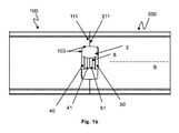
図1aは、本開示の第1の実施形態によるプレス工具1の部分分解図を示す。プレス工具1は、金属粉末もしくはセラミック粉末またはこれらの混合などの粉末を切削インサート素地体にプレスするように構成されている。プレス工具1は、第1のプレス軸Aに沿って、互いに向かって移動可能な第1の上方ポンチ8と第2の下方ポンチ9とを含む。プレス工具1は、第2の軸Bに沿って、互いに向かってかつ互いから離れて移動可能な第1のダイ部材100と第2のダイ部材200とをさらに含む。第1のポンチ8および第2のポンチ9の組と第1のダイ部材100および第2のダイ部材200の組とは、第1のプレス軸Aと第2の軸Bとが互いに対して非平行配向であるように配置されている。したがって、図1aに示されているプレス工具1は垂直プレス工具であり、したがって、第1のプレス軸Aは垂直軸である。第2の軸Bは水平軸であり、したがって、第1のプレス軸Aに対して垂直に配向されている。図1aに示されているプレス工具1は多軸プレス機械内で利用されることが意図されている。
FIG. 1a shows a partially exploded view of the
図1aに示されている実施形態では、第1のダイ部材100および第2のダイ部材200それぞれが、ダイ部101、201と、プレス機械(図示せず)の様々な構成要素がこれによりプレス工具1に取り付けられ得る取付けブロック102、202とを含む。例えば、ダイ部材100、200を移動させる駆動ユニット。図1a~図1dでは、取付けブロック102、202およびダイ部101、102は、例えばボルト継ぎ手により結合されている個別構成要素である。しかし、また、ダイ部材100、200を一体ユニットに設計することが可能である。その場合、各ダイ部材100、200は、1つだけの細長いダイ部101、201により構成される。
In the embodiment shown in FIG. 1a, the
ダイ部材100、200の移動が、ボールねじ機構(図示せず)により、第1のダイ部材100および第2のダイ部材200の各端部110、210に接続されている、電動機などの電気駆動により達成されてもよい。また、油圧シリンダ(図示せず)などの、他のタイプの線形アクチュエータを使用して、第1のダイ部材100および第2のダイ部材200を互いに向かってかつこれから離して移動させることが可能である。
The movement of the
また、第1のポンチ8および第2のポンチ9の移動が、前述されている電気駆動または油圧シリンダにより達成されてもよい。
Further, the movement of the
第1のダイ部材100および第2のダイ部材200は、それぞれ、ダイ部材100、200の対向する前端部109、209に形成されているダイキャビティ面103、203を含む。ダイ部材100、200の該前端部109、209は各ダイ接触面111、211をさらに含んでいてもよい。
The
また、第1のポンチ8および第2のポンチ9は、第1のポンチ8および第2のポンチ9の対向する前端部10、11に形成されている各形成面12、13を含む。
Further, the
図1aでは、第2のポンチ9の形成面13および第2のダイ部材200のダイキャビティ面203のみが、図面の斜視に因り可視である。しかし、第1のポンチ8の形成面12および第1のダイ部材100のダイキャビティ面103の位置は点線矢印により示されており、第2のダイ部材のダイキャビティ面203および第2のポンチ9の形成面13の位置に対応している。
In FIG. 1a, only the forming
本開示の一実施形態によれば、プレス工具1は、第1のダイ部材100内に配置されている第1のコア部分40と、第2のダイ部材200内に配置されている第2のコア部分50とを含む。第1のコア部分40は第1のダイ部材100のダイキャビティ面103から延出しており、すなわち突出しており、第2のコア部分50は第2のダイ部材200のダイキャビティ面203から延出している、すなわち突出している。図1aに示されている実施形態では、第1のコア部分40および第2のコア部分50は、それぞれ、第2の軸Bに平行な方向に、ダイキャビティ面103、203から延出している。しかし、また、コア部分40、50は他の配向を有し得ると考えられる。
According to one embodiment of the present disclosure, the
第1のダイ部材100および第2のダイ部材200のダイキャビティ面103、203と第1のポンチ8および第2のポンチ9の形成面12、13とは、コア部分40、50と共に、プレス工具1内で製造される切削インサート素地体の所望の幾何学的形態および表面構造を与えるように設計されている。
The
図1bを参照する。動作中、第1のダイ部材100および第2のダイ部材200は、軸Bに沿って、ダイキャビティ3が第1のダイキャビティ面103と第2のダイキャビティ面203との間に形成されている端部位置まで、互いに向かって移動させられる。図1bは、ダイ部材100、200が端部位置にある状態の、プレス工具1の部分の上方からの図を示す。図1bに示されている実施形態では、第1のダイ部材100および第2のダイ部材200のダイ接触面111、211は互いに当接している。しかし、ダイ部材100、200が端部位置にある場合、ダイ部材100、200上の磨耗を回避するために、小間隙すなわち遊び(図示せず)もまた、ダイ接触面111と211との間に存在することが分かる。第1のコア部分40および第2のコア部分50はダイキャビティ内へ延出しており、ダイキャビティ3を貫通してコア6を形成している。したがって、第1のコア部分40はコア6の第1の部分を形成しており、第2のコア部分50はコア6の第2の部分を形成している。コア6は切削インサート内に貫通孔、例えば十字孔、をもたらす。互いに相互係合するために、図1a、図1bの実施形態に示されているコア部分40、50の各前部41、51が、他方のコア部分の接触面(接触面56が図1cに示されている)と当接するように構成されている接触面46、56を設けられていてもよい。しかし、ある環境下で、例えばコア部分40、50の磨耗に因り、または意図的に磨耗を回避するために、コア部分40、50の接触面46と56との間に小さい遊びが存在し得ることが分かる。しかし、第1のコア部分40と第2のコア部分50とは互いに係合しておりかつダイキャビティ3を貫通する連続コア6を形成することが好ましい。
See FIG. 1b. During operation, the
例えば、接触面46、56は平面である。各コア部分40、50の長さすなわち軸方向延長部は、コア部分40、50がダイキャビティ内で係合するように選択されることが分かる。図1bでは、第1のコア部分40および第2のコア部分50は長さが等しく、ダイキャビティの中心で互いに係合する。しかし、また、一方のコア部分が他方のコア部分(図示せず)より長いように異なる軸方向延長部を有して、コア部分40、50を設計することが可能である。これの利点が、コア部分40、50が係合する、切削インサート素地体の十字孔内に形成される可能性があるめくれ(flash)すなわちプレスばりの位置(軸方向位置)を制御する可能性である。
For example, the contact surfaces 46 and 56 are flat. It can be seen that the length or axial extension of each
図1cは、コア部分50と接触面56とを含む、第2のダイ部材200の前端部209の斜視図を示す。また、図1cは、本実施形態では平面すなわち真っ直ぐな外形である、第2のダイ部材200のダイ接触面211の構造を示す。しかし、ダイ接触面211は他の構造(図示せず)、例えば非平坦、であることが可能である。ダイ接触面111、211の構造は、切削インサート素地体の幾何学的形状に依存して選択される。第1の部材と第2の部材との間の分割線が、ダイ部材が切削インサート素地体から離れて(軸Bの方向に)移動すること、および切削インサート素地体を損傷することなくダイキャビティ3を開くことを可能にする位置にある必要があるので、これはこのようになっている。第1のダイ部材100のダイ接触面111(図示せず)は第2のダイ部材200のダイ接触面211に対応して構成されていることが分かる。
FIG. 1c shows a perspective view of the
また、第1のコア部分40および第2のコア部分50の他の構造が、本明細書の最後に説明される通り可能である。
Also, other structures of the
さらに、本開示の例示的実施形態によれば、第1のコア部分40および第2のコア部分50が、軸Bに沿って、端部位置に向かってかつこれから離れて、第1のダイ部材および第2のダイ部材と一緒に移動させられるように、第1のコア部分40および第2のコア部分50は各第1のダイ部材100および第2のダイ部材200に結合されている。これにより、コア部分40、50は、以下に説明される通り、第1のダイ部材100および第2のダイ部材200に解除可能に取り付けられていることが好ましい。コア部分40、50は磨耗に晒され、時々交換される必要があるので、解除可能な取付けは有利である。コア部分40、50はダイ部101、201より頻繁に交換されることが求められる。
Further, according to an exemplary embodiment of the present disclosure, the
図1aに戻って、第1のダイ部材100は、ダイキャビティ面103から第1のダイ部材100の後端部110に向かって延在している穴部105を含む。相応に、第2のダイ部材200は、ダイキャビティ面203から第2のダイ部材200の後端部210に向かって延在している穴部205を含む。記載されている実施形態では、穴部105、205は、ダイキャビティ面103、203から、ダイ部101、201を貫通して、各ダイ部材100、200の取付けブロック102、202へ延在している。しかし、該穴部は任意の長さであってもよい。例えば、穴部は、ダイキャビティ面から各ダイ部材100、200の後端部までの貫通孔であってもよい。また、穴部は、ダイ部材100、200内の止まり穴であってもよい。
Returning to FIG. 1a, the
第1のコア部分40は、第1のコア部分40の前部41から離れる方向に延在しているピン42を含む。第2のコア部分50は、第2のコア部分50の前部51から離れる方向に延在しているピン52を含む。前部41、51は図1bに示されている。第1のコア部分40および第2のコア部分50ならびにこれらの各ピン41、51は、これにより一体であってもよい、すなわち1個の部品にまたは例えばはんだ付けにより結合されている2つの別個の部品で形成されていてもよい。
The
穴部105、205内にあるピンが、各ダイ部材100、200の後端部110、210に向かって延在しているように、かつコア部分40、50が各ダイキャビティ面103、203から延在しているように、コア部分40、50のピン42、52は、第1のダイ部材100および第2のダイ部材200にある各穴部105、205内に配置されている、すなわち挿入されている。
The pins in the
記載されている実施形態では、第1のコア部分40および第2のコア部分50は、第1のコア部分40および第2のコア部分50を各第1のダイ部材100および第2のダイ部材200に機械的に結合することにより、各第1のダイ部材100および第2のダイ部材200に解除可能に取り付けられている。機械的結合は、各第1のダイ部材100および第2のダイ部材200内での第1のコア部分40および第2のコア部分50の形状適合(form-fitting)により達成されてもよい。図1aに示されている実施形態では、第1のピン42および第2のピン52は、形状適合係合で、第1のダイ部材100および第2のダイ部材200にある各凹部107、207内に受容される各ロック部材45、55に取り付けられている。
In the described embodiment, the
図1dは第1のダイ部材100の分解図を示す。図1dに示されている特徴および以下の説明もまた、第2のダイ部材200に有効であることが分かる。
FIG. 1d shows an exploded view of the
前述の通り、第1のダイ部材100は、第1のダイ部材100を通って、ダイキャビティ面103から第1のダイ部材100の端110に向かって延在している穴部105を含む。第1のダイ部材100は、穴部105の端106に配置されている凹部107をさらに含む。記載されている実施形態では、凹部107は、第1のダイ部101に隣接して、第1の取付けブロック102内に配置されている。しかし、凹部107は、あるいは、第1のダイ部101内にまたは第1のダイ部材100の端110に配置されていてもよい。また、凹部107およびこれの機能は、一方は第1の取付けブロック102内に配置されておりかつ他方は第1のダイ部101内に配置されている2つの合致する凹部(図示せず)を組み合わせることにより達成されてもよい。
As described above, the
第1のコア部分40のピン42は、第1のダイ部材100にある凹部107(図1aに示されている)内に受容されるように構成されているロック部材45を含む。該ロック部材45は、コア部分40のピン42の端43に配置されていてもよい。通常、ロック部材45が固定されて凹部107内に受容され、保持されて、コア部分40の回転移動および/または並進移動を制限するかまたは防止するように、ロック部材45および凹部107は対応する形状および寸法を有する。したがって、図1aおよび図1dに示されている実施形態では、凹部107およびロック部材45は矩形形状であり、軸Bの方向に見た、凹部107とロック部材45の幅(w)とは同一のまたは少なくとも対応する寸法である。凹部107の高さ(h)は、(図1dに示されている通り)ロック部材45の高さ(h)より大きい。しかし、また、ロック部材45および凹部107の高さ(h)は同一であってもよく、これにより、ロック部材45と凹部107との間に密な形状適合がもたらされる。また、凹部107の深さ(d)とロック部材45の厚さ(t)とが対応しているまたは同一の寸法であり、コア部分40の回転移動および/または並進移動を制限する。
The
第1のコア部分40のピン42は、ピン42の端43をロック部材45にある穴部48内に挿入することにより、ロック部材45に取り付けられ、そしてピン42の端43をロック部材45に接着で取り付けてもよい。接着取付けは、例えば糊付けまたははんだ付けにより、達成され得る。また、例えばピンを金属固体ブロックから機械加工で作り出すことにより、ピンをロック部材と一体で形成することが可能である。
The
また、ロック機能は、例えばダウエルピン連結を用いることによるなど、他のロック原理により達成されてもよい。一代替案(図示せず)によれば、円筒形ダウエルピンが、締まり嵌めで、好ましくは軸Bに対して垂直な方向に、第1のダイ部材100およびコア部分40のピン42の両方を貫通して延在している円筒形穴部内に挿入され、これにより、回転移動および/または並進移動を制限するかまたは防止する。該円筒形ダウエルピンは、円筒形穴部に対応する直径を有し、遊びを防止する。
Further, the locking function may be achieved by other locking principles, for example by using a dowel pin connection. According to one alternative (not shown), the cylindrical dowel pin penetrates both the
ピン構造の他の例およびコア部分をダイ部材に結合する他の方法が明細書の最後に記載される。 Other examples of pin structures and other methods of connecting core portions to die members are described at the end of the specification.
図1aに描写されているプレス工具1は長手方向横断面図で示されていること、およびいくつかの構成要素が他の構成要素を可視化するために除去されていることが分かる。完全性のために、図2はプレス工具1の斜視全体図を示す。したがって、プレス工具1は、前述されている構成要素に加えて、第1のダイ部101および第2のダイ部201と、ダイ/フィルテーブル(fill table)14とを封入しているダイ部材ホルダ7を含む。また、第1のダイ部材100および第2のダイ部材200の第1のポンチ8および第2のポンチ9ならびに取付けブロック102、202が図2において可視である。
It can be seen that the
プレス工具1は、第3の軸に沿って端部位置に向かってかつこれから離れて移動可能な第3のダイ部材および第4のダイ部材などの、ダイ部材(図示せず)をさらに含んでいてもよいことがさらに分かる。該第3のダイ部材および該第4のダイ部材はコア部分を含んでいてもよいか、または含んでいなくてもよい。また、プレス工具は、第1のコア部分および第2のコア部分より多くを含んでいてもよい。例えば、第1のダイ部材は第1のコア部分と第2のコア部分とを含んでいてもよく、第2のダイ部材は第3のコア部分と第4のコア部分とを含んでいてもよい。また、プレス工具は、第3のポンチおよび第4のポンチなどのさらなるポンチを含むことが可能である。
The
本開示によるプレス工具1は、以下において、プレスサイクルのステップを示す図3a~図3eを参照して記載される。
The
図3aは、第1のダイ部材100と第2のダイ部材200とが端部位置から離れて移動させられた初期位置にあるプレス工具1を示す。コア部分40、50は、各第1のダイ部材100および第2のダイ部材200のダイキャビティ面103、203から延出している。第1の上方ポンチ8は第1のダイ部材100および第2のダイ部材200の上方に持ち上げられ、第2の下方ポンチ9は第1のダイ部材100および第2のダイ部材200の前端部109と209との間の位置にある。
FIG. 3a shows the
図3bは、第1のダイ部材100と第2のダイ部材200とが軸Bに沿って端部位置へ互いに向かう方向に移動させられた場合のプレス工具1を示す。第1のダイ部材100および第2のダイ部材200のダイ接触面111、211は互いに接触しており、ダイキャビティ3が第1のダイ部材100および第2のダイ部材200のダイキャビティ面103と203との間に形成されている。第1のダイ部材100および第2のダイ部材200に結合されている第1のコア部分40および第2のコア部分50は、第1のダイ部材100および第2のダイ部材200と一緒に移動させられており、ここで、ダイキャビティ3内へ延出しており、ダイキャビティ3を貫通するコア6を形成している。ダイ部材100およびダイ部材200の端部位置では、ダイキャビティ3は、第1の上方ポンチ8を受容する第1の上方開口部4と、第2の下方ポンチ9を受容する第2の下方開口部5とを含む。この位置では、粉末が、例えばフィルシュー(fill shoe)(図示せず)により、ダイキャビティ内へ導入される。
FIG. 3b shows the
図3cでは、第1の上方ポンチ8はダイキャビティ3の第1の開口部4内に受容されており、第1のポンチ8および第2のポンチ9は第1のプレス軸Aに沿って互いに向かって移動させられ、ダイキャビティ内の粉末を切削インサート素地体2に加圧成形する。
In FIG. 3c, the first
図3dでは、ダイキャビティ3は、第1のダイ部材100および第2のダイ部材200を、端部位置から、第2の軸Bに沿って、互いから離して移動させることにより開いている。これにより、第1のコア部分40および第2のコア部分50は第1のダイ部材100および第2のダイ部材200と一緒に移動させられ、切削インサート素地体にある貫通孔から後退させられる。
In FIG. 3d, the
図3eでは、切削インサート素地体は、第1の上方ポンチ8(図示せず)および第2の下方ポンチ9を上方に移動させることにより、プレス工具1から取り出されている。その後、第1の上方ポンチ8(図示せず)はさらに持ち上げられて、切削インサート素地体2が回収されることを可能にする。
In FIG. 3e, the cutting insert substrate is removed from the
以下では、図1a~図1dに示されている第1の実施形態のプレス工具1の、以下の様々な代替案が説明される。これらの代替案の説明では、第1の実施形態と異なる特徴のみが示され、詳細に説明される。しかし、また、これらの代替案は第1の実施形態の適切な特徴を含み、これらと完全に互換性があることが分かる。
In the following, the following various alternatives of the
図4は、第1のコア部分40および第2のコア部分50が各第1のダイ部材100および第2のダイ部材200と一体である、プレス工具1の代替案を示す。これにより、該コア部分40、50と各第1のダイ部材100および第2のダイ部材200とは、各々、コア部分40、50が各ダイ部材100、200と永久的に結合されている単一の部品を形成している。例えば、第1のコア部分40および第2のコア部分50とダイ部材100、200とは、それぞれ、例えば放電加工またはフライス加工により、単一の金属部品から形成されていてもよい。
FIG. 4 shows an alternative to the
図5は、第1のコア部分40および第2のコア部分50が雌/雄構造である、プレス工具1の代替案を示す。これにより、第1のコア部分40の前部41は第2のコア部分50の前部51の凹部57内に受容されるように構成されている。第1の例示的実施形態との比較では、雌/雄構造のコア部分の使用が、連続コアを達成するための、各コア部分の接触面間の当接の必要を省く。したがって、コア部分の雌/雄構造は、コア部分の長さ寸法の精度がより低くても、コア部分間の係合を実現する。あるいは、第1のコア部分40の前部41は雌構造であってもよく、第2のコア部分50の前部51は雄構造であってもよいことが分かる。
FIG. 5 shows an alternative to the
また、図5は、第1のコア部分40および第2のコア部分50それぞれが、各第1のダイ部材100および第2のダイ部材200のダイキャビティ面103、203上に載るように構成されている肩状部44、54を含む、プレス工具1のさらなる代替案を示す。該肩状部44、54は、コア部分40、50の端が閉じたダイキャビティ内で係合する場合、これが、コア部分が互いをダイ部材100、200の穴部105、205内へ押し込まないようにするので、有利である。あるいは、第1のコア部分40と第2のコア部分50の一方のみが肩状部を含んでいてもよいことが分かる。
Further, FIG. 5 is configured such that the
図6は、第2のダイ部材200のダイキャビティ面203が、穴部205を取り囲みかつ図5に示されているコア部分50の肩状部54を支持するように構成されている環状載置面(annular resting surface)208を含む、プレス工具1のさらなる代替案を示す。また、第1のダイ部材100のキャビティ面103は載置面108(図示せず)を含んでいてもよい。該載置面208の利点は、これが、肩状部54への密な接触を実現するために、非常に高精度に、例えば平面に、機械加工され得る、ダイ表面の限られた区分を構成することである。
FIG. 6 shows an annular mounting in which the
図7は、第1のコア部分40と第2のコア部分50のうちの一方の全圧縮剛性が第1のコア部分40および第2のコア部分50のうちの他方の全圧縮剛性より大きい、代替案を示す。本体の圧縮剛性は、弾性変形に対して本体により与えられる抵抗の尺度である。全圧縮剛性は、本開示では、第1のコア部分40および第2のコア部分50の材料組成により制御され得る。すなわち、例えば、コア部分40、50のうちの一方は、第1のピン42および第2のピン52のうちの他方の材料と異なる剛性の材料で構成されていてもよい。また、全圧縮剛性は、第1のコア部分および第2のコア部分の幾何学的寸法により制御されてもよい。例えば、第1のコア部分40と第2のコア部分50のうちの一方のピン42、52は、第1のコア部分および第2のコア部分のうちの他方のピン42、52より大きい横断面積を有していてもよい。また、第1のコア部分40および第2のコア部分50の材料組成と幾何学的寸法との組合せにより、全圧縮剛性を制御することが可能である。
FIG. 7 shows that the total compressive stiffness of one of the
図7に示されている実施形態では、ピンは同一材料であるが、第2のコア部分50のピン52は第1のコア部分40のピン42より小さい横断面積を有する。したがって、第2のコア部分50のピン52は第1のコア部分40のピン42より圧縮剛性が低い。全圧縮剛性の差異は、第1のコア部分40と第2のコア部分50とがダイキャビティ3内で係合した場合、第2のピン52が降伏するという結果になる。これは、より低い全圧縮剛性を有するピン52がばねとしての機能を果たしかつ第1のコア部分40のより粗いピン42からの力の下で屈曲するという結果になる。この構造の利点は、これが第1のコア部分および第2のコア部分の軸方向延長部の寸法の不正確さを補償することである。すなわち、第1のピン42および第2のピン52の全圧縮剛性の差異は、コア部分40、50の過剰な長さを自己補償する。また、コア部分の軸方向延長部を意図的に過剰な寸法で作製し(over-dimension)、ばね効果を用いて、第1のコア部分と第2のコア部分との間の完全な密な接触を確実することが可能である。
In the embodiment shown in FIG. 7, the pins are made of the same material, but the
図8は部分分解図であり、コア部分50が、コア部分50のピン52の少なくとも部分とダイ部材200にある穴部205との間での接着剤の塗布により、第2のダイ部材200に解除可能に取り付けられているように構成されている、プレス工具1の代替案を示す。接着剤(図示せず)は、通常、ピン52を穴部205内へ挿入する前に、ピン52の少なくとも部分上に塗布される。あるいは、接着剤は、ピン52を穴部205内へ挿入する前に、該穴部内に塗布される。接着剤は糊、例えばLoctite 6300またはLoctite 3090、の形であってもよい。また、接着剤ははんだ、例えばMeltolit 449 MPまたはMeltolit WC 75、の形であってもよい。糊およびはんだは低温状態でピンを穴部に強力に取り付けるが、加熱されると軟化し、これによりピンおよびコア部分を除去することが可能になるので、これらの物質はどちらも有利である。
FIG. 8 is a partial exploded view, wherein the
ピン52の少なくとも部分の寸法は、ピン52と穴部205との間に接着剤を塗布するために十分な空間が存在するように選択されることが分かる。また、接着剤はピン52の全長に塗布されてもよく、これにより、ピン52と穴部205との間に強力な結合がもたらされることが分かる。あるいは、接着剤は単にピン52の部分に塗布される。例えば、接着剤の塗布はピン52の後端部53に限定されていてもよい。次いで、ピンを除去するために、ダイ部材200の小区分だけを加熱して、接着剤を軟化すればよい。
It can be seen that the dimensions of at least a portion of the
図9は、図4に示されているように、第2のコア部分50が第2のダイ部材200と一体である、プレス工具1の代替案を示す。しかし、本代替案によれば、第2のダイ部材200は、第2のコア部分50を通って延在している第2の穴部205を含む。第2のピン52の端が第2のコア部分50の前部51から外に延出しているように、プレス工具1は、第2のコア部分50から離れておりかつ第2の穴部205を通って延在している第2のピン52をさらに含む。この構造に関する1つの利点が、コア部分50とダイキャビティ面203との間に界面が存在せず、一方、ピン52が穴部205内で屈曲する可能性があることである。コア部分50とダイキャビティ面203との間の界面の欠如は、粉末がコア部分50とダイキャビティ面203との間に進入しかつ切削インサート素地体上にめくれまたは跡を形成する可能性を排除する。また、第1のダイ部材100は、第1のコア部分40を通って延在している穴部105と、前述されているように配置されているピン42とを含んでいてもよいこと(図示せず)が分かる。
FIG. 9 shows an alternative to the
第1の実施形態および様々な代替案は様々な組合せに組み合わされ得ることが分かる。例えば、図4に示されている、ダイ部材と一体で形成されているコア部分が、図5に示されている雌/雄構造を設けられていてもよい。または、図5のピンは図7に示されている寸法を与えられていてもよい。または、図7のプレス工具1のコア部分40を含む第1のダイ部材100は、一体のコア部分40を有する、図4の第1のダイ部材100と置き換えられていてもよい。
It can be seen that the first embodiment and the various alternatives can be combined in various combinations. For example, the core portion, which is shown in FIG. 4 and is integrally formed with the die member, may be provided with the female / male structure shown in FIG. Alternatively, the pins of FIG. 5 may be given the dimensions shown in FIG. Alternatively, the
さらに、第1のピン42および第2のピン52は非円形横断面を有していてもよく、第1の穴部105および第2の穴部205は、対応する非円形横断面を有していてもよい(図示せず)。これは、第1のコア部分40および第2のコア部分50が穴部内で回転しないようにされること、およびしたがって、コア部分が正確な整合でロックされることを確実にする。
Further, the
各第1のダイ部材および第2のダイ部材内の第1のコア部分および第2のコア部分が同軸に配置されてもよいことがさらに分かる。すなわち、これにより、第1のコア部分40および第2のコア部分50は、第1のコア部分および第2のコア部分の端が互いに対向するように整合される。これは、切削インサート素地体内の精密な貫通孔をもたらす。
It is further found that the first core portion and the second core portion within each first die member and second die member may be arranged coaxially. That is, thereby, the
以上に、本開示によるプレス工具1の第1の例示的実施形態を、ダイキャビティ3を貫通してコア6を一緒に形成する第1のコア部分40および第2のコア部分50を有するプレス工具1に関して記載した。しかし、第2の例示的実施形態によれば、プレス工具1は、第1のダイ部材100または第2のダイ部材200内に配置されている少なくとも1つのコア部分40、50を含んでいてもよい。少なくとも1つのコア部分40、50は、第1のダイ部材100および第2のダイ部材200が端部位置にある場合、ダイキャビティ3を貫通してコア6を形成するように構成されている。
As described above, the first exemplary embodiment of the
図10aは、本開示の第2の例示的実施形態によるプレス工具1の側面図を概略的に示す。第2の例示的実施形態によるプレス工具1は、第1の例示的実施形態において説明されているプレス工具と同一であり、これの全特徴を含み、差異は、第2の例示的実施形のプレス工具が、第1のコア部分40および第2のコア部分50の代りに、1つだけのコア部分40を含むことのみであることが分かる。
FIG. 10a schematically shows a side view of the
したがって、図10aに示されているプレス工具1では、第1のダイ部材100および第2のダイ部材200は、第1のダイ部材100と第2のダイ部材200との間にダイキャビティ3が形成されている端部位置にある。第1のポンチおよび第2のポンチは図10aでは不可視である。第1のコア部分40が第1のダイ部材100内に配置されており、第1のダイ部材100のダイキャビティ面103から、ダイキャビティ3を通って、第2のダイ部材200のダイキャビティ面203まで延在している。これにより、第1のコア部分40は、ダイキャビティ3を貫通してコア6を形成している。これにより、連続コア6がダイキャビティ3を貫通して形成されるように、第1のコア部分40の接触面46は第2のダイ部材200のダイキャビティ面203と係合していてもよい。しかし、第1の例示的実施形態において記載されている通り、第1のコア部分40の接触面46と第2のダイ部材のダイキャビティ面203との間に小さい遊びが存在していてもよい。
Therefore, in the
あるいは、少なくとも1つのコア部分が第2のダイ部材200内に配置されている可能性があることが分かる。図10bは、本開示の第2の例示的実施形態によるプレス工具1の斜視図を概略的に示す。1つだけのコア部分50は第2のダイ部材200内に配置されており、第2のダイキャビティ面203から、ダイキャビティ3を通って、第1のダイ部材100の第1のキャビティ面103(図示せず)まで延在しているコア6を形成している。
Alternatively, it can be seen that at least one core portion may be located within the
Claims (13)
- 前記第1のプレス軸(A)に非平行である少なくとも第2の軸(B)に沿って、端部位置に向かってかつこれから離れて移動可能に配置されている第1のダイ部材(100)および第2のダイ部材(200)とを備える、切削インサート素地体(2)を製造するためのプレス工具(1)であって、
- 前記第1のダイ部材(100)は第1のダイキャビティ面(103)を含み、前記第2のダイ部材(200)は第2のダイキャビティ面(203)を含み、前記ダイ部材(100、200)は、前記端部位置に、前記第1のポンチ(8)および前記第2のポンチ(9)を受容する第1の開口部(4)および第2の開口部(5)を有するダイキャビティ(3)を形成するように構成されており、さらに、
- 前記第1のダイ部材(100)および前記第2のダイ部材(200)が前記端部位置にある場合、前記ダイキャビティ(3)を貫通して、前記第1のダイキャビティ面(103)と前記第2のダイキャビティ面(203)との間に延在しているコア(6)と、
- 前記コア(6)の少なくとも部分を形成する第1のコア部分(40)と
を備え、
前記第1のコア部分(40)は、前記第1のダイ部材(100)または前記第2のダイ部材(200)内に配置されており、前記第1のコア部分(40)は、前記第1のダイ部材(100)または前記第2のダイ部材(200)と一緒に前記端部位置へ移動させられるように、前記第1のダイ部材(100)または前記第2のダイ部材(200)に結合されており、前記第1のコア部分(40)は、前記第1のダイ部材(100)または前記第2のダイ部材(200)に解除可能に取り付けられている、プレス工具(1)。 -With the first punch (8) and the second punch (9), which are arranged so as to be movable toward and away from each other along the first press axis (A).
-A first die member that is movably arranged towards and away from the end position along at least a second axis (B) that is non-parallel to the first press axis (A). A press tool (1) for manufacturing a cutting insert substrate (2), comprising 100) and a second die member (200).
-The first die member (100) includes a first die cavity surface (103), the second die member (200) includes a second die cavity surface (203), and the die member (100). , 200) have a first opening (4) and a second opening (5) at the end position to receive the first punch (8) and the second punch (9). It is configured to form a die cavity (3), and further
-When the first die member (100) and the second die member (200) are at the end positions, the first die cavity surface (103) penetrates the die cavity (3). And the core (6) extending between the second die cavity surface (203) and
-With a first core portion (40 ) forming at least a portion of the core (6).
The first core portion (40 ) is arranged in the first die member (100) or the second die member (200), and the first core portion (40 ) is , The first die member (100) or the second die so that it can be moved to the end position together with the first die member (100) or the second die member (200). A press that is coupled to a member (200) and the first core portion (40) is releasably attached to the first die member (100) or the second die member (200). Tool (1).
One of claims 1 to 12 , wherein the first core portion (40 ) includes a shoulder portion (44, 54) configured to rest on the die cavity surface (103, 203). The press tool (1) according to item 1.
Applications Claiming Priority (3)
| Application Number | Priority Date | Filing Date | Title |
|---|---|---|---|
| EP16177300.7 | 2016-06-30 | ||
| EP16177300.7A EP3263249B1 (en) | 2016-06-30 | 2016-06-30 | A press-tool |
| PCT/EP2017/066232 WO2018002282A1 (en) | 2016-06-30 | 2017-06-29 | A press-tool |
Publications (3)
| Publication Number | Publication Date |
|---|---|
| JP2019527297A JP2019527297A (en) | 2019-09-26 |
| JP2019527297A5 JP2019527297A5 (en) | 2021-08-19 |
| JP6991166B2 true JP6991166B2 (en) | 2022-01-12 |
Family
ID=56296693
Family Applications (1)
| Application Number | Title | Priority Date | Filing Date |
|---|---|---|---|
| JP2018568962A Active JP6991166B2 (en) | 2016-06-30 | 2017-06-29 | Press tool |
Country Status (6)
| Country | Link |
|---|---|
| US (1) | US11285535B2 (en) |
| EP (1) | EP3263249B1 (en) |
| JP (1) | JP6991166B2 (en) |
| KR (1) | KR102325177B1 (en) |
| CN (1) | CN109475935B (en) |
| WO (1) | WO2018002282A1 (en) |
Families Citing this family (2)
| Publication number | Priority date | Publication date | Assignee | Title |
|---|---|---|---|---|
| US11504932B2 (en) * | 2017-11-30 | 2022-11-22 | Bayer Healthcare Llc | Die insertion tool |
| CN116689760A (en) * | 2023-06-30 | 2023-09-05 | 宁波迈泰克磁材科技有限公司 | Sintered NdFeB forming equipment and method |
Citations (4)
| Publication number | Priority date | Publication date | Assignee | Title |
|---|---|---|---|---|
| JP2006513317A (en) | 2002-11-04 | 2006-04-20 | ケンナメタル インコーポレイテッド | Method and apparatus for performing cross-hole molding to produce cutting inserts |
| JP2011505258A (en) | 2007-11-27 | 2011-02-24 | ケンナメタル インコーポレイテッド | Method and apparatus for compression molding a part using a split case mold and part manufactured thereby |
| JP2014528838A (en) | 2011-08-14 | 2014-10-30 | イスカーリミテッド | Apparatus and method for manufacturing a cutting insert |
| CN104368811A (en) | 2014-11-26 | 2015-02-25 | 江西稀有稀土金属钨业集团有限公司 | Die and method for pressing special-shaped powder product |
Family Cites Families (22)
| Publication number | Priority date | Publication date | Assignee | Title |
|---|---|---|---|---|
| GB121239A (en) * | 1918-03-19 | 1918-12-12 | William John Mellersh-Jackson | Improvements in Methods of and Apparatus for Making Bodies of Elastic Material. |
| US3720491A (en) * | 1970-07-15 | 1973-03-13 | Burroughs Corp | Apparatus for forming articles from powdered metal |
| DK546377A (en) * | 1977-12-08 | 1979-06-09 | O P Olling | PROCEDURE FOR THE PREPARATION OF POWDER-PRESSED ITEMS AND TOOLS FOR CARRYING OUT THE PROCEDURE |
| US4408807A (en) * | 1981-02-11 | 1983-10-11 | The Charles Stark Draper Laboratory, Inc. | Compression molding of porous retainers |
| US5378416A (en) * | 1992-07-28 | 1995-01-03 | Nissan Motor Co., Ltd. | Method of and system for manufacturing powder moldings |
| IT1260870B (en) * | 1992-10-16 | 1996-04-29 | Gt B Components Limited | MOLDING PROCEDURE OF AN ITEM PROVIDED WITH AT LEAST ONE HOLE, MOLD USABLE IN THE PROCEDURE AND ARTICLE OBTAINABLE FROM THE PROCEDURE |
| US6113378A (en) * | 1996-08-28 | 2000-09-05 | Minebea Co., Ltd. | Mold for drum-shaped magnetic core |
| DE19635183A1 (en) * | 1996-08-30 | 1998-03-05 | Krebsoege Sinterholding Gmbh | Procedure for calibrating a preformed recess |
| JPH10118796A (en) * | 1996-10-18 | 1998-05-12 | Mitsubishi Materials Corp | Method and device for producing green compact having horizontal hole |
| JP4348750B2 (en) * | 1998-04-21 | 2009-10-21 | 日産自動車株式会社 | Powder molding apparatus and driving method thereof |
| JP3558531B2 (en) * | 1998-08-31 | 2004-08-25 | 日立粉末冶金株式会社 | Powder molding equipment |
| JP2002307199A (en) * | 2001-04-11 | 2002-10-22 | Kobayashi Kogyo Kk | Powder compression molding method, and device therefor |
| KR200297708Y1 (en) * | 2002-08-12 | 2002-12-12 | (주)대림엠티아이 | Die set apparatus for trimming yoke |
| IL166530A (en) | 2005-01-27 | 2009-06-15 | Iscar Ltd | Method for manufacturing cutting inserts |
| US7829015B2 (en) * | 2007-05-31 | 2010-11-09 | Borgwarner Inc. | Formation of non-axial features in compacted powder metal components |
| US8033805B2 (en) | 2007-11-27 | 2011-10-11 | Kennametal Inc. | Method and apparatus for cross-passageway pressing to produce cutting inserts |
| US8029724B2 (en) * | 2007-12-27 | 2011-10-04 | Sandvik Intellectual Property Ab | Method of making a cutting insert with a hole for clamping |
| US20140086695A1 (en) * | 2012-09-25 | 2014-03-27 | Kennametal Inc. | Processes and apparatuses for making cutting tool inserts |
| EP2808106B1 (en) | 2013-05-30 | 2019-11-06 | Sandvik Intellectual Property AB | Method for manufacturing a cutting insert |
| AT14230U1 (en) * | 2014-02-17 | 2015-06-15 | Ceratizit Austria Gmbh | Mold, method of making a green compact and use of the mold |
| CN205110783U (en) * | 2015-08-19 | 2016-03-30 | 宁波凌珂新材料科技有限公司 | Suppression device of powder forming spare with cross bore |
| CN204975328U (en) * | 2015-09-02 | 2016-01-20 | 苏州永佳超硬耐磨材料有限公司 | An abnormal shape dry pressing device |
-
2016
- 2016-06-30 EP EP16177300.7A patent/EP3263249B1/en active Active
-
2017
- 2017-06-29 KR KR1020187037814A patent/KR102325177B1/en active IP Right Grant
- 2017-06-29 CN CN201780039713.0A patent/CN109475935B/en active Active
- 2017-06-29 WO PCT/EP2017/066232 patent/WO2018002282A1/en active Application Filing
- 2017-06-29 JP JP2018568962A patent/JP6991166B2/en active Active
- 2017-06-29 US US16/311,479 patent/US11285535B2/en active Active
Patent Citations (4)
| Publication number | Priority date | Publication date | Assignee | Title |
|---|---|---|---|---|
| JP2006513317A (en) | 2002-11-04 | 2006-04-20 | ケンナメタル インコーポレイテッド | Method and apparatus for performing cross-hole molding to produce cutting inserts |
| JP2011505258A (en) | 2007-11-27 | 2011-02-24 | ケンナメタル インコーポレイテッド | Method and apparatus for compression molding a part using a split case mold and part manufactured thereby |
| JP2014528838A (en) | 2011-08-14 | 2014-10-30 | イスカーリミテッド | Apparatus and method for manufacturing a cutting insert |
| CN104368811A (en) | 2014-11-26 | 2015-02-25 | 江西稀有稀土金属钨业集团有限公司 | Die and method for pressing special-shaped powder product |
Also Published As
| Publication number | Publication date |
|---|---|
| WO2018002282A1 (en) | 2018-01-04 |
| KR102325177B1 (en) | 2021-11-10 |
| CN109475935B (en) | 2021-06-29 |
| US20190240731A1 (en) | 2019-08-08 |
| JP2019527297A (en) | 2019-09-26 |
| EP3263249B1 (en) | 2019-01-23 |
| CN109475935A (en) | 2019-03-15 |
| KR20190024907A (en) | 2019-03-08 |
| EP3263249A1 (en) | 2018-01-03 |
| US11285535B2 (en) | 2022-03-29 |
Similar Documents
| Publication | Publication Date | Title |
|---|---|---|
| US20170282254A1 (en) | Method and arrangement for manufacturing a cutting insert | |
| US7560068B2 (en) | Method and apparatus for manufacturing a cutting insert | |
| CN102458735B (en) | A tool for chip removing machining as well as a solid indexable cutting insert and a solid basic body therefor | |
| JP6991166B2 (en) | Press tool | |
| JP6875515B2 (en) | Cemented Carbide Pressed Product Manufacturing Method and Equipment and Cemented Carbide Pressed Product | |
| EP2242601B1 (en) | Method of making a cutting insert with a hole for clamping | |
| JP2011505258A (en) | Method and apparatus for compression molding a part using a split case mold and part manufactured thereby | |
| US20100159051A1 (en) | Method and apparatus for cross-passageway pressing to produce cutting inserts | |
| IT201800003877A1 (en) | EXTRACTOR DEVICE FOR MOLDS | |
| CN104718036B (en) | Method and apparatus for manufacturing coated cutting tool | |
| KR20190136012A (en) | Compacting device and method for manufacturing cutting insert green body by compacting powder | |
| JPH11129102A (en) | Manufacture of throw-away chip and throw-away chip | |
| JP7236397B2 (en) | Cutting plate and method and compression mold for manufacturing cutting plate green body | |
| JP2023520722A (en) | Press tool and method for forming cutting insert green bodies with through holes | |
| EP3698901B1 (en) | A press tool |
Legal Events
| Date | Code | Title | Description |
|---|---|---|---|
| A621 | Written request for application examination |
Free format text: JAPANESE INTERMEDIATE CODE: A621 Effective date: 20200430 |
|
| A977 | Report on retrieval |
Free format text: JAPANESE INTERMEDIATE CODE: A971007 Effective date: 20210308 |
|
| A131 | Notification of reasons for refusal |
Free format text: JAPANESE INTERMEDIATE CODE: A131 Effective date: 20210406 |
|
| A524 | Written submission of copy of amendment under article 19 pct |
Free format text: JAPANESE INTERMEDIATE CODE: A524 Effective date: 20210706 |
|
| TRDD | Decision of grant or rejection written | ||
| A01 | Written decision to grant a patent or to grant a registration (utility model) |
Free format text: JAPANESE INTERMEDIATE CODE: A01 Effective date: 20211130 |
|
| A61 | First payment of annual fees (during grant procedure) |
Free format text: JAPANESE INTERMEDIATE CODE: A61 Effective date: 20211207 |
|
| R150 | Certificate of patent or registration of utility model |
Ref document number: 6991166 Country of ref document: JP Free format text: JAPANESE INTERMEDIATE CODE: R150 |