JP6989397B2 - Time measurement circuit - Google Patents
Time measurement circuit Download PDFInfo
- Publication number
- JP6989397B2 JP6989397B2 JP2018003183A JP2018003183A JP6989397B2 JP 6989397 B2 JP6989397 B2 JP 6989397B2 JP 2018003183 A JP2018003183 A JP 2018003183A JP 2018003183 A JP2018003183 A JP 2018003183A JP 6989397 B2 JP6989397 B2 JP 6989397B2
- Authority
- JP
- Japan
- Prior art keywords
- signal
- clock
- circuit
- input
- output
- Prior art date
- Legal status (The legal status is an assumption and is not a legal conclusion. Google has not performed a legal analysis and makes no representation as to the accuracy of the status listed.)
- Active
Links
Images


Landscapes
- Electric Clocks (AREA)
Description
本発明は、高分解能な時間測定を行うことが可能な時間計測回路に関するものである。 The present invention relates to a time measurement circuit capable of performing high resolution time measurement.
psecオーダーの高分解能な時間測定を行う場合、論理回路のゲート遅延を用いるTDC(Time-to-Digital Converter)と呼ばれる手法(非特許文献1参照)が広く知られている。ただし、非特許文献1に開示されている構成では時間計測範囲を広げれば広げるほど接続する遅延回路を増やすこととなるため、実際はNutt Method(非特許文献2参照)と呼ばれる低速カウンタと高速カウンタを併用して時間計測を行う手法がよく用いられる(以降、本願で述べるTDCは全てNutt Methodを適用した計測方式とする。)。
When performing high-resolution time measurement on the order of psec, a method called TDC (Time-to-Digital Converter) using a gate delay of a logic circuit (see Non-Patent Document 1) is widely known. However, in the configuration disclosed in
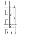
Nutt Methodは、高速クロックの動作期間を図17の開始信号Startの立ち上がりからクロックCLKrefの立ち上がりまでの期間、および停止信号Stopの立ち上がりからクロックCLKrefの立ち上がりまでの期間のみとし、これらの時間間隔ΔTstart,ΔTstopを高速クロックを用いて計測する手法である。 The Nut Method limits the operating period of the high-speed clock to only the period from the rising edge of the start signal Start to the rising edge of the clock CLK ref in FIG. 17 and the period from the rising edge of the stop signal Stop to the rising edge of the clock CLK ref. This is a method of measuring ΔT start and ΔT stop using a high-speed clock.
開始信号Startの立ち上がり直後のクロックCLKrefの立ち上がりから停止信号Stopの立ち上がり直後のクロックCLKrefの立ち上がりまでの期間NTrefを低速カウンタで測定すれば、開始信号Startの立ち上がりから停止信号Stopの立ち上がりまでの時間間隔ΔTinを次式のように求めることができる。
ΔTin=NTref+ΔTstart−ΔTstop ・・・(1)
By measuring the period NT ref from the rising of the clock CLK ref immediately rise of the start signal Start to rising of the clock CLK ref immediately after rise of the stop signal Stop at a low speed counter from the rising of the start signal Start to the rising of the stop signal Stop The time interval ΔT in of can be obtained by the following equation.
ΔT in = NT ref + ΔT start −ΔT stop・ ・ ・ (1)
Nutt Methodによれば、高速クロックによる2回の時間計測期間は、それぞれ低速クロックCLKrefの1周期よりも短くなる。Nutt Methodを用いる場合、低速カウンタと高速カウンタの位相を合わせるためにDLL(Delay Locked Loop)、またはPLL(Phase Locked Loop)をベースとしたTDCを用いるのが一般的である。しかしながら、DLLやPLLはクロックの発振の安定化に例えば5〜10μsec(低速カウンタの周波数を4MHz、高速カウンタの周波数を630MHzとした場合)の時間を要するので、時間計測開始前にTDCを動作させておく必要があり、低消費電力化の実現が難しいという問題点があった。 According to Nut Method, the two time measurement periods by the high-speed clock are shorter than one cycle of the low-speed clock CLKref, respectively. When the Nut Method is used, it is common to use a TDC based on a PLL (Delay Locked Loop) or a PLL (Phase Locked Loop) in order to match the phases of the low-speed counter and the high-speed counter. However, the PLL and PLL require, for example, 5 to 10 μsec (when the frequency of the low-speed counter is 4 MHz and the frequency of the high-speed counter is 630 MHz) to stabilize the oscillation of the clock, so the TDC is operated before the start of time measurement. There was a problem that it was difficult to realize low power consumption.
例えばガスメータ向け超音波流量計は、超音波の伝搬時間差を低消費電力かつ高分解能で測定する必要があるため、高速カウンタの動作期間(高速クロックの発振期間)をできる限り短くする必要がある。しかし、上記のとおりDLL方式のTDCとPLL方式のTDCは遅延回路の発振安定化に時間を要するため、高速クロックの発振期間が長くなり消費電力面で不利である。 For example, an ultrasonic flow meter for a gas meter needs to measure the propagation time difference of ultrasonic waves with low power consumption and high resolution, so that the operating period of a high-speed counter (high-speed clock oscillation period) needs to be as short as possible. However, as described above, the DLL type TDC and the PLL type TDC require time to stabilize the oscillation of the delay circuit, so that the oscillation period of the high-speed clock becomes long, which is disadvantageous in terms of power consumption.
TDCの動作時間(高速クロックの発振時間)を最小にする他の構成として、例えば特許文献1に開示されたリングオシレータ型の構成も考えられる。しかしながら、リングオシレータ型のTDCでは、TDCに入力される開始信号と停止信号のタイミングによってRSフリップフロップ回路や遅延回路(Dラッチ)の出力信号がメタステーブル状態となってしまうことがある。
As another configuration that minimizes the operating time of the TDC (oscillation time of the high-speed clock), for example, a ring oscillator type configuration disclosed in
このように、リングオシレータ型のTDCでは、内部で使用されているRSフリップフロップ回路へのRESET信号とSET信号が競合することにより、RSフリップフロップ回路の出力信号がメタステーブル状態となる可能性があるため、正確な時間測定を行うことができないという課題があった。 In this way, in the ring oscillator type TDC, there is a possibility that the output signal of the RS flip-flop circuit will be in the metastable state due to the conflict between the SET signal and the SET signal to the RS flip-flop circuit used internally. Therefore, there is a problem that accurate time measurement cannot be performed.
本発明は、上記課題を解決するためになされたもので、低消費電力と、開始信号と停止信号の入力タイミングによらない正確で高分解能な時間測定とを両立させることができる時間計測回路を提供することを目的とする。 The present invention has been made to solve the above problems, and is a time measurement circuit capable of achieving both low power consumption and accurate and high-resolution time measurement regardless of the input timing of a start signal and a stop signal. The purpose is to provide.
本発明の時間計測回路は、外部から入力される第1のクロックを数えるように構成された第1のカウンタと、時間計測の開始信号または停止信号の入力のタイミングであるSET入力のタイミングで有意となり、RESET入力のタイミングで無意となる発振許可信号を出力するように構成されたフリップフロップ回路と、前記発振許可信号が有意の期間中に前記第1のクロックよりも高速な第2のクロックを生成するように構成された発振回路と、前記第2のクロックを数えるように構成された第2のカウンタと、前記第1のカウンタの計数結果と前記第2のカウンタの計数結果とを基に前記開始信号の入力から前記停止信号の入力までの時間間隔を算出するように構成された時間算出回路と、前記開始信号および前記停止信号と前記第1のクロックとから生成した発振停止信号を、前記フリップフロップ回路に前記RESET入力として与えるように構成された制御回路とを備え、前記制御回路は、前記SET入力のタイミングから前記RESET入力のタイミングまでの期間が前記第1のクロックの1周期以上3周期以下の期間となる前記発振停止信号を生成することを特徴とするものである。
The time measurement circuit of the present invention is significant in terms of the first counter configured to count the first clock input from the outside and the timing of SET input, which is the timing of input of the start signal or stop signal of time measurement. A flip flop circuit configured to output an unexpected oscillation permission signal at the timing of the RESET input, and a second clock faster than the first clock during a period in which the oscillation permission signal is significant. Based on the oscillation circuit configured to generate, the second counter configured to count the second clock, the counting result of the first counter, and the counting result of the second counter. A time calculation circuit configured to calculate a time interval from the input of the start signal to the input of the stop signal, and an oscillation stop signal generated from the start signal, the stop signal, and the first clock. The flip flop circuit is provided with a control circuit configured to be given as the RESET input, and the control circuit has a period from the timing of the SET input to the timing of the RESET input for one cycle or more of the first clock. It is characterized in that the oscillation stop signal having a period of three cycles or less is generated.
また、本発明の時間計測回路の1構成例において、前記制御回路は、前記開始信号および前記停止信号の入力の度に反転する検出信号を出力するように構成された検出信号生成回路と、前記検出信号を、前記第1のクロックの1クロック分遅延させた第1の遅延信号を出力するように構成された第1のDフリップフロップ回路と、前記第1の遅延信号を、前記第1のクロックの1/2クロック分遅延させた第2の遅延信号を出力するように構成された第2のDフリップフロップ回路と、前記第2の遅延信号を、前記第1のクロックの1/2クロック分遅延させた第3の遅延信号を出力するように構成された第3のDフリップフロップ回路と、前記第3の遅延信号が入力されたタイミングで有意となり、次の第1のクロックが入力されたタイミングで無意となる前記発振停止信号を生成するように構成された発振停止信号生成回路と、前記発振停止信号を、前記第1のクロックの1/2クロック分遅延させた取り込み許可信号を出力するように構成された第4のDフリップフロップ回路とから構成され、前記時間算出回路は、前記取り込み許可信号が有意となるタイミングで前記第2のカウンタの計数結果を取り込むことを特徴とするものである。
また、本発明の時間計測回路の1構成例において、前記第2のカウンタは、前記発振停止信号が有意から無意へと変わるタイミングで計数結果を0に初期化することを特徴とするものである。
また、本発明の時間計測回路の1構成例において、前記制御回路は、前記取り込み許可信号が有意となるタイミングで前記取り込み許可信号を微分した結果をリセット信号として出力するように構成された微分回路をさらに備え、前記第2のカウンタは、前記リセット信号が有意となるタイミングで計数結果を0に初期化することを特徴とするものである。
Further, in one configuration example of the time measurement circuit of the present invention, the control circuit includes a detection signal generation circuit configured to output a detection signal that is inverted each time the start signal and the stop signal are input. The first D flipflop circuit configured to output the first delay signal obtained by delaying the detection signal by one clock of the first clock, and the first delay signal are the first delay signal. A second D flipflop circuit configured to output a second delay signal delayed by 1/2 clock of the clock and the second delay signal are combined with the 1/2 clock of the first clock. It becomes significant at the timing when the third D flip flop circuit configured to output the third delay signal delayed by a minute and the third delay signal is input, and the next first clock is input. Outputs an oscillation stop signal generation circuit configured to generate the oscillation stop signal that becomes unintentional at the same timing, and an capture permission signal in which the oscillation stop signal is delayed by 1/2 clock of the first clock. It is composed of a fourth D flip flop circuit configured to perform the above, and the time calculation circuit is characterized in that the counting result of the second counter is fetched at the timing when the fetch permission signal becomes significant. Is.
Further, in one configuration example of the time measurement circuit of the present invention, the second counter is characterized in that the counting result is initialized to 0 at the timing when the oscillation stop signal changes from significant to unexpected. ..
Further, in one configuration example of the time measurement circuit of the present invention, the control circuit is a differentiating circuit configured to output the result of differentiating the capture permission signal as a reset signal at the timing when the capture permission signal becomes significant. The second counter is characterized in that the counting result is initialized to 0 at the timing when the reset signal becomes significant.
また、本発明の時間計測回路の1構成例において、前記制御回路は、前記開始信号および前記停止信号の入力の度に反転する検出信号を出力するように構成された検出信号生成回路と、前記検出信号を、前記第1のクロックの1/2クロック分遅延させた第1の遅延信号を出力するように構成された第1のDフリップフロップ回路と、前記第1の遅延信号を、前記第1のクロックの1/2クロック分遅延させた第2の遅延信号を出力するように構成された第2のDフリップフロップ回路と、前記第2の遅延信号を、前記第1のクロックの1/2クロック分遅延させた第3の遅延信号を出力するように構成された第3のDフリップフロップ回路と、前記第2の遅延信号と前記第3の遅延信号との排他的論理和の結果を、前記発振停止信号および取り込み許可信号として出力するように構成された排他的論理和回路と、前記取り込み許可信号が無意となるタイミングで前記取り込み許可信号を微分した結果をリセット信号として出力するように構成された微分回路とから構成され、前記時間算出回路は、前記取り込み許可信号が有意となるタイミングで前記第2のカウンタの計数結果を取り込み、前記第2のカウンタは、前記リセット信号が有意となるタイミングで計数結果を0に初期化することを特徴とするものである。 Further, in one configuration example of the time measurement circuit of the present invention, the control circuit includes a detection signal generation circuit configured to output a detection signal that is inverted each time the start signal and the stop signal are input. The first D flipflop circuit configured to output the first delay signal obtained by delaying the detection signal by 1/2 clock of the first clock, and the first delay signal are the first. A second D flipflop circuit configured to output a second delay signal delayed by 1/2 clock of one clock, and the second delay signal are one-third of the first clock. The result of the exclusive logical sum of the third D flipflop circuit configured to output the third delay signal delayed by two clocks, the second delay signal, and the third delay signal. , The exclusive logic sum circuit configured to output as the oscillation stop signal and the capture permission signal, and the result of differentiating the capture permission signal at the timing when the capture permission signal becomes unintentional are output as a reset signal. It is composed of a differential circuit configured, and the time calculation circuit captures the counting result of the second counter at the timing when the capture permission signal becomes significant, and the second counter captures the reset signal. It is characterized in that the counting result is initialized to 0 at the timing.
また、本発明の時間計測回路の1構成例において、前記制御回路は、前記開始信号および前記停止信号の入力の度に反転する検出信号を出力するように構成された検出信号生成回路と、前記検出信号を、前記第1のクロックの1クロック分遅延させた第1の遅延信号を出力するように構成された第1のDフリップフロップ回路と、前記第1の遅延信号を、前記第1のクロックの1クロック分遅延させた第2の遅延信号を出力するように構成された第2のDフリップフロップ回路と、前記第2の遅延信号を、前記第1のクロックの1クロック分遅延させた第3の遅延信号を出力するように構成された第3のDフリップフロップ回路と、前記第3の遅延信号が入力されたタイミングで有意となり、次の第1のクロックが入力されたタイミングで無意となる前記発振停止信号を生成するように構成された発振停止信号生成回路と、前記発振停止信号を、前記第1のクロックの1/2クロック分遅延させた取り込み許可信号を出力するように構成された第4のDフリップフロップ回路とから構成され、前記時間算出回路は、前記取り込み許可信号が有意となるタイミングで前記第2のカウンタの計数結果を取り込むことを特徴とするものである。 Further, in one configuration example of the time measurement circuit of the present invention, the control circuit includes a detection signal generation circuit configured to output a detection signal that is inverted each time the start signal and the stop signal are input. The first D flipflop circuit configured to output the first delay signal obtained by delaying the detection signal by one clock of the first clock, and the first delay signal are the first delay signal. The second D flipflop circuit configured to output the second delay signal delayed by one clock of the clock and the second delay signal are delayed by one clock of the first clock. It becomes significant at the timing when the third D flipflop circuit configured to output the third delay signal and the third delay signal are input, and is unintentional at the timing when the next first clock is input. The oscillation stop signal generation circuit configured to generate the oscillation stop signal and the capture permission signal obtained by delaying the oscillation stop signal by 1/2 clock of the first clock are output. It is composed of the fourth D flip flop circuit, and the time calculation circuit is characterized in that the counting result of the second counter is fetched at the timing when the fetch permission signal becomes significant.
本発明によれば、第1のカウンタとフリップフロップ回路と発振回路と第2のカウンタと時間算出回路とを設け、さらにSET入力のタイミングからRESET入力のタイミングまでの期間が第1のクロックの1周期以上3周期以下の期間となる発振停止信号を生成してフリップフロップ回路のRESET入力として与える制御回路を設けることにより、低消費電力化と、開始信号と停止信号の入力タイミングによらない正確で高分解能な時間測定とを両立させることができる。 According to the present invention, a first counter, a flip-flop circuit, an oscillation circuit, a second counter, and a time calculation circuit are provided, and the period from the SET input timing to the RESET input timing is 1 of the first clock. By providing a control circuit that generates an oscillation stop signal with a period of 1 cycle or more and 3 cycles or less and gives it as the RESET input of the flip-flop circuit, the power consumption is reduced and the start signal and the stop signal are accurately input regardless of the input timing. It is possible to achieve both high-resolution time measurement.
また、本発明では、取り込み許可信号が有意となるタイミングで取り込み許可信号を微分した結果を第2のカウンタのリセット信号として出力する微分回路を設けることにより、2つの停止信号間の受け付け可能間隔を短縮することができる。 Further, in the present invention, the acceptable interval between the two stop signals is set by providing a differentiating circuit that outputs the result of differentiating the capture permission signal as the reset signal of the second counter at the timing when the capture permission signal becomes significant. Can be shortened.
また、本発明では、取り込み許可信号が無意となるタイミングで取り込み許可信号を微分した結果を第2のカウンタのリセット信号として出力する微分回路を設けることにより、2つの停止信号間の受け付け可能間隔をさらに短縮することができる。 Further, in the present invention, the acceptable interval between the two stop signals is set by providing a differentiating circuit that outputs the result of differentiating the capture permission signal as the reset signal of the second counter at the timing when the capture permission signal becomes unintentional. It can be further shortened.
[第1の実施例]
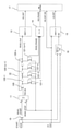
以下、本発明の実施例について図面を参照して説明する。図1は本発明の第1の実施例に係る時間計測回路の構成を示す回路図である。時間計測回路は、リングオシレータ型TDC1と、リングオシレータ型TDC制御回路2とを備えている。
[First Example]
Hereinafter, examples of the present invention will be described with reference to the drawings. FIG. 1 is a circuit diagram showing a configuration of a time measurement circuit according to a first embodiment of the present invention. The time measurement circuit includes a ring
リングオシレータ型TDC1は、外部から入力される、時間計測の開始信号STARTと停止信号STOPの論理和の結果を発振開始信号ROSC_STARTとして出力するOR回路10と、発振開始信号ROSC_START(開始信号STARTと停止信号STOP)をSET入力とし、リングオシレータ型TDC制御回路2から出力された発振停止信号ROSC_STOPをRESET入力とし、発振許可信号TDC_ENを出力するRSフリップフロップ回路11と、発振許可信号TDC_ENが有意の期間中に高速クロックROSC_CLK(第2のクロック)を生成するリングオシレータ12(発振回路)と、高速クロックROSC_CLKをカウントする高速カウンタ13(第2のカウンタ)と、発振停止信号ROSC_STOPのタイミングを示すタイミング信号HS_PHASEを出力するデコーダ14と、外部から入力される低速クロックLS_CLK(第1のクロック)をカウントする低速カウンタ15(第1のカウンタ)と、低速カウンタ15のカウント開始/停止を制御する低速クロックイネーブル作成回路16と、高速カウンタ13の計数結果HS_CNTと低速カウンタ15の計数結果LS_CNTとを基に、開始信号STARTの立ち上がりから停止信号STOPの立ち上がりまでの時間間隔を算出する時間算出回路17とから構成される。
The ring oscillator type TDC1 has an
リングオシレータ12は、発振許可信号TDC_ENと高速クロックROSC_CLKとの論理積をとるAND回路120と、AND回路120の出力に縦続接続された複数のインバータ回路120−1〜120−n(nは2以上の整数)と、AND回路120と各インバータ回路120−1〜120−nの出力をそれぞれD入力とし、発振停止信号ROSC_STOPをクロック入力とする複数のDフリップフロップ回路121−1〜121−(n+1)とから構成される。
The
リングオシレータ型TDC制御回路2は、発振開始信号ROSC_STARTをクロック入力とし、発振開始信号ROSC_STARTの立ち上がりの度に反転する検出信号ST_DETを出力するDフリップフロップ回路20と、検出信号ST_DETの反転信号をDフリップフロップ回路20のD入力とするインバータ回路21と、検出信号ST_DETをD入力、低速クロックLS_CLKをクロック入力として、低速クロックLS_CLKの立ち上がりで検出信号ST_DETを取り込み、検出信号ST_DETを遅延させた信号ST_DET_SYNC_1D(第1の遅延信号)を出力するDフリップフロップ回路22と、Dフリップフロップ回路22から出力された信号ST_DET_SYNC_1DをD入力、低速クロックLS_CLKをクロック入力として、低速クロックLS_CLKの立ち下がりで信号ST_DET_SYNC_1Dを取り込み、信号ST_DET_SYNC_1Dを遅延させた信号ST_DET_SYNC_2D(第2の遅延信号)を出力するDフリップフロップ回路23と、Dフリップフロップ回路23から出力された信号ST_DET_SYNC_2DをD入力、低速クロックLS_CLKをクロック入力として、低速クロックLS_CLKの立ち上がりで信号ST_DET_SYNC_2Dを取り込み、信号ST_DET_SYNC_2Dを遅延させた信号ST_DET_SYNC_3D(第3の遅延信号)を出力するDフリップフロップ回路24と、発振停止信号ROSC_STOPを生成する発振停止信号生成回路25と、発振停止信号ROSC_STOPをD入力、低速クロックLS_CLKをクロック入力として、高速カウンタ13の計数結果HS_CNTの取り込み許可信号HS_CNT_ENを出力するDフリップフロップ回路26とから構成される。
The ring oscillator type
Dフリップフロップ回路20とインバータ回路21とは、検出信号ST_DETを生成する検出信号生成回路33を構成している。
The D flip-
以下、本実施例の時間計測回路の動作を説明する。図2は時間計測回路の動作を説明するタイミングチャートである。
OR回路10は、開始信号STARTと停止信号STOPの論理和の結果を、図2に示すような発振開始信号ROSC_STARTとして出力する。
Hereinafter, the operation of the time measurement circuit of this embodiment will be described. FIG. 2 is a timing chart illustrating the operation of the time measurement circuit.
The OR
リングオシレータ型TDC制御回路2のDフリップフロップ回路20とインバータ回路21とは、図2に示すように発振開始信号ROSC_STARTの立ち上がりの度に反転する検出信号ST_DETを出力する。すなわち、検出信号ST_DETは、開始信号STARTまたは停止信号STOPの入力の度に反転する。
As shown in FIG. 2, the D flip-
RSフリップフロップ回路11は、発振開始信号ROSC_STARTをSET入力とし、後述のようにリングオシレータ型TDC制御回路2から出力された発振停止信号ROSC_STOPをRESET入力とし、図2に示すように発振開始信号ROSC_STARTの立ち上がりで有意(High)となり、発振停止信号ROSC_STOPの立ち上がりで無意(Low)となる発振許可信号TDC_ENを出力する。すなわち、RSフリップフロップ回路11は、開始信号STARTまたは停止信号STOPの立ち上がりで有意となる発振許可信号TDC_ENを出力する。
The RS
リングオシレータ12は、RSフリップフロップ回路11から出力された発振許可信号TDC_ENが有意の期間中に、図2に示すように、低速クロックLS_CLKよりも高速なクロックROSC_CLKを生成する。
高速カウンタ13は、リングオシレータ型TDC制御回路2から出力された発振停止信号ROSC_STOPが無意(Low)の期間中に、高速クロックROSC_CLKをカウントして計数結果HS_CNTを出力する。
The
The high-
デコーダ14は、Dフリップフロップ回路121−1〜121−(n+1)の出力ROSC_PHASEを基に、発振停止信号ROSC_STOPのタイミングを示すタイミング信号HS_PHASEを出力する。
The
リングオシレータ型TDC制御回路2のDフリップフロップ回路22は、検出信号ST_DETをD入力、低速クロックLS_CLKをクロック入力として、低速クロックLS_CLKの立ち上がりで検出信号ST_DETを取り込み、図2に示すように検出信号ST_DETを、低速クロックLS_CLKの1クロック分遅延させた信号ST_DET_SYNC_1Dを出力する。
The
リングオシレータ型TDC制御回路2のDフリップフロップ回路23は、Dフリップフロップ回路22から出力された信号ST_DET_SYNC_1DをD入力、低速クロックLS_CLKをクロック入力として、低速クロックLS_CLKの立ち下がりで信号ST_DET_SYNC_1Dを取り込み、図2に示すように信号ST_DET_SYNC_1Dを、低速クロックLS_CLKの1/2クロック分遅延させた信号ST_DET_SYNC_2Dを出力する。
The D
リングオシレータ型TDC制御回路2のDフリップフロップ回路24は、Dフリップフロップ回路23から出力された信号ST_DET_SYNC_2DをD入力、低速クロックLS_CLKをクロック入力として、低速クロックLS_CLKの立ち上がりで信号ST_DET_SYNC_2Dを取り込み、図2に示すように信号ST_DET_SYNC_2Dを、低速クロックLS_CLKの1/2クロック分遅延させた信号ST_DET_SYNC_3Dを出力する。
The D
リングオシレータ型TDC制御回路2の発振停止信号生成回路25は、信号ST_DET_SYNC_2D,ST_DET_SYNC_3Dと低速クロックLS_CLKとを入力とし、信号ST_DET_SYNC_3Dの立ち上がりで有意(High)となり、次の低速クロックLS_CLKの立ち上がりで無意(Low)となる発振停止信号ROSC_STOPを生成する。
The oscillation stop
図3は発振停止信号生成回路25の構成例を示す回路図である。発振停止信号生成回路25は、信号ST_DET_SYNC_2DとST_DET_SYNC_3Dとの排他的論理和をとるXOR回路250と、“0 ”(Low)を第1の入力とし、XOR回路250の出力を第2の入力とし、発振停止信号ROSC_STOPを制御入力とし、制御入力が“1 ”(High)のときに第1の入力側を選択して出力し、制御入力が“0 ”のときに第2の入力側を選択して出力するセレクタ251と、セレクタ251の出力をD入力とし、低速クロックLS_CLKをクロック入力として、発振停止信号ROSC_STOPを出力するDフリップフロップ回路252とから構成される。
FIG. 3 is a circuit diagram showing a configuration example of the oscillation stop
発振停止信号ROSC_STOPが有意(High)になると、上記のとおり発振許可信号TDC_ENが無意(Low)となるので、リングオシレータ12による高速クロックROSC_CLKの生成が停止する。
When the oscillation stop signal ROSC_STOP becomes significant (High), the oscillation permission signal TDC_EN becomes involuntary (Low) as described above, so that the
リングオシレータ型TDC制御回路2のDフリップフロップ回路26は、発振停止信号ROSC_STOPをD入力、低速クロックLS_CLKをクロック入力として、低速クロックLS_CLKの立ち下がりで発振停止信号ROSC_STOPを取り込み、図2に示すように発振停止信号ROSC_STOPを、低速クロックLS_CLKの1/2クロック分遅延させた取り込み許可信号HS_CNT_ENを出力する。
The D flip-
一方、低速カウンタ15は、低速クロックLS_CLKをカウントして計数結果LS_CNTを出力する。
低速クロックイネーブル作成回路16は、開始信号STARTの立ち上がりで低速カウンタ15に低速クロックLS_CLKのカウントを開始させ、停止信号STOPの立ち上がりで低速クロックLS_CLKのカウントを停止させて計数結果LS_CNTを0に初期化させる。なお、超音波流量計のように1回の開始信号STARTに対して複数回の停止信号STOPが入力される場合には、低速クロックイネーブル作成回路16は、1回のSTOP毎ではなく、最後の停止信号STOPの受け付け後に(後述する図15の例では4回受け付け後)に計数結果LS_CNTを0に初期化させる。
On the other hand, the
The low-speed clock enable
時間算出回路17は、取り込み許可信号HS_CNT_ENが有意(High)になった時点で高速カウンタ13の計数結果HS_CNTを取り込む。
また、本実施例では、発振停止信号ROSC_STOPが高速カウンタ13のCLR(クリア)入力となっているので、高速カウンタ13は、発振停止信号ROSC_STOPの立ち下がりのタイミング(有意から無意へと変わるタイミング)でリセットされ、計数結果HS_CNTを0に初期化する。
The
Further, in this embodiment, since the oscillation stop signal ROSC_STOP is the CLR (clear) input of the high-
時間算出回路17は、開始信号STARTを契機とする発振開始信号ROSC_STARTの出力により開始される高速カウンタ13の計数の結果HS_CNTに基づいて、図17のΔTstartに相当する時間間隔を算出することができる。また、時間算出回路17は、停止信号STOPを契機とする発振開始信号ROSC_STARTの出力により開始される高速カウンタ13の計数の結果HS_CNTに基づいて、図17のΔTstopに相当する時間間隔を算出することができる。
The
また、時間算出回路17は、開始信号STARTに応じた発振開始信号ROSC_STARTの直後に出力される発振停止信号ROSC_STOPのタイミングを示すタイミング信号HS_PHASEと、停止信号STOPに応じた発振開始信号ROSC_STARTの直後に出力される発振停止信号ROSC_STOPのタイミングを示すタイミング信号HS_PHASEと、これら2つのタイミング間の低速カウンタ15の計数結果LS_CNTと基づいて、図17のNTrefに相当する時間間隔を算出することができる。したがって、時間算出回路17は、式(1)と同様に開始信号STARTの立ち上がりから停止信号STOPの立ち上がりまでの時間間隔ΔTinを算出することができる。
Further, the
本実施例では、RSフリップフロップ回路11の出力をメタステーブル状態にさせないタイミング(SET入力(ROSC_START)とRESET入力(ROSC_STOP)とが競合しないタイミング)で発振停止信号ROSC_STOPを有意にするリングオシレータ型TDC制御回路2を追加することにより、開始信号STARTと停止信号STOPの入力タイミングによらず正確な時間計測結果を得ることができるようにしている。
In this embodiment, the ring oscillator type TDC that makes the oscillation stop signal ROSC_STOP significant at the timing when the output of the RS flip-
本実施例では、リングオシレータ型TDC制御回路2を加えることにより、高速クロックROSC_CLKの発振期間が、低速クロックLS_CLKの1周期以上2周期以下の期間となるようにしている。本実施例では、Dフリップフロップ回路22,24を低速クロックLS_CLKの立ち上がりに同期させ、Dフリップフロップ回路23を低速クロックLS_CLKの立ち下がりに同期させることで、上記のような高速クロックROSC_CLKの発振期間の設定を実現している。
In this embodiment, the ring oscillator type
従来のNutt Methodの思想と比較すると、本実施例では、高速クロックROSC_CLKの発振期間が長くなるが、発振開始信号ROSC_STARTと発振停止信号ROSC_STOPとの間が少なくとも低速クロックLS_CLKの1周期分確保されるため、RSフリップフロップ回路11のSET入力とRESET入力の競合が生じることはない。
Compared with the conventional idea of Nut Method, in this embodiment, the oscillation period of the high-speed clock ROSC_CLK is longer, but at least one cycle of the low-speed clock LS_CLK is secured between the oscillation start signal ROSC_START and the oscillation stop signal ROSC_STOP. Therefore, there is no conflict between the SET input and the RESET input of the RS flip-
図2に示したように発振開始信号ROSC_STARTが低速クロックLS_CLKの立ち上がり付近で入力された場合に計測実行時間は最大となる(低速クロックを4MHzとすると、3×(1/4MHz)=750ns)。したがって、連続して停止信号STOPを入力する場合、停止信号STOPと次の停止信号STOP間は最低750ns空ける必要がある。 As shown in FIG. 2, when the oscillation start signal ROSC_START is input near the rising edge of the low-speed clock LS_CLK, the measurement execution time becomes maximum (3 × (1/4 MHz) = 750 ns when the low-speed clock is 4 MHz). Therefore, when the stop signal STOP is continuously input, it is necessary to leave at least 750 ns between the stop signal STOP and the next stop signal STOP.
こうして、本実施例では、リングオシレータ型TDC1の採用による低消費電力化と、開始信号STARTと停止信号STOPの入力タイミングによらない正確で高分解能な時間測定とを両立させることができる。 In this way, in this embodiment, it is possible to achieve both low power consumption by adopting the ring oscillator type TDC1 and accurate and high-resolution time measurement regardless of the input timing of the start signal START and the stop signal STOP.
本実施例との比較のため、従来のリングオシレータ型TDCの構成を図4に示す。この構成は、Nutt Methodを従来のリングオシレータ型TDCに適用したものである。図4の構成のうち、本実施例に相当する構成要素には、図1と同一の符号を付してある。 For comparison with this embodiment, the configuration of the conventional ring oscillator type TDC is shown in FIG. This configuration is an application of Nut Method to a conventional ring oscillator type TDC. Of the configurations shown in FIG. 4, the components corresponding to the present embodiment are designated by the same reference numerals as those in FIG.
図5は図4のリングオシレータ型TDCの動作を説明するタイミングチャートである。低速クロックLS_CLKの周波数を4MHzとすると、低速カウンタ15は250nsの分解能で時間を計測することができる。開始信号STARTの立ち上がりから次の低速クロックLS_CLKの立ち上がりまでのTDC計測期間#1(ΔTstart)および停止信号STOPの立ち上がりから次の低速クロックLS_CLKの立ち上がりまでのTDC計測期間#2(ΔTstop)のような250nsに満たない期間は高速カウンタ13で計測される。この計測期間は、開始信号STARTもしくは停止信号STOPが入力されたタイミングにより、0〜250nsの範囲で変化する。
FIG. 5 is a timing chart illustrating the operation of the ring oscillator type TDC of FIG. Assuming that the frequency of the low-speed clock LS_CLK is 4 MHz, the low-
図5の例では、低速クロックLS_CLKの立ち上がりの直後に開始信号STARTが立ち上がっているため、TDC計測期間#1は低速クロックLS_CLKの周期(250ns)に近くなる。
一方、低速クロックLS_CLKの立ち上がりの直前に停止信号STOPが立ち上がっているため、TDC計測期間#2は0nsに近くなる。
In the example of FIG. 5, since the start signal START rises immediately after the rise of the low-speed clock LS_CLK, the TDC
On the other hand, since the stop signal STOP rises immediately before the rise of the low-speed clock LS_CLK, the TDC
本実施例でも説明したとおり、リングオシレータ12の発振許可信号TDC_ENは、RSフリップフロップ回路11の出力である。通常、このRSフリップフロップ回路11の入力であるRESET入力(図4の例では低速クロックLS_CLK)とSET入力(図4の例では発振開始信号ROSC_START、すなわち開始信号STARTもしくは停止信号STOP)との間には、使用時にユーザーが保障しなければならない時間の制約が存在する。
As described in this embodiment, the oscillation permission signal TDC_EN of the
上記のとおり低速クロックLS_CLKの周波数を4MHzとすると、高速クロックROSC_CLKの発振期間は0〜250nsの範囲である。この発振期間は、発振開始信号ROSC_STARTの立ち上がりから発振停止信号ROSC_STOP(図4の例では低速クロックLS_CLK)の立ち上がりまでの期間となる。 As described above, assuming that the frequency of the low-speed clock LS_CLK is 4 MHz, the oscillation period of the high-speed clock ROSC_CLK is in the range of 0 to 250 ns. This oscillation period is the period from the rise of the oscillation start signal ROSC_START to the rise of the oscillation stop signal ROSC_STOP (low-speed clock LS_CLK in the example of FIG. 4).
この発振開始信号ROSC_STARTと発振停止信号ROSC_STOPの2つの立ち上がりの時間差が短くなった場合(例えば1ns)、RSフリップフロップ回路11の出力(発振許可信号TDC_EN)がメタステーブル状態となり、高速クロックROSC_CLKを入力とする高速カウンタ13が誤動作する可能性がある。すなわち、RSフリップフロップ回路11のSET入力の立ち上がりからRESET入力の立ち上がりまでの時間を1ns以上空ける必要がある、という制約が存在する。
When the time difference between the two rising edges of the oscillation start signal ROSC_START and the oscillation stop signal ROSC_STOP becomes short (for example, 1 ns), the output of the RS flip-flop circuit 11 (oscillation permission signal TDC_EN) is in the metastable state, and the high-speed clock ROSC_CLK is input. There is a possibility that the high-
時間計測開始を示す開始信号STARTおよび時間計測停止を示す停止信号STOPは当然、低速クロックLS_CLKとは非同期で入力される。したがって、図4に示したような構成では、開始信号STARTもしくは停止信号STOPの入力タイミング次第で、上記の制約を満たすことができなくなり、正確な時間測定が不可能となる。 Naturally, the start signal START indicating the start of time measurement and the stop signal STOP indicating the stop of time measurement are input asynchronously with the low-speed clock LS_CLK. Therefore, in the configuration as shown in FIG. 4, depending on the input timing of the start signal START or the stop signal STOP, the above constraint cannot be satisfied, and accurate time measurement becomes impossible.
そこで、本実施例では、リングオシレータ型TDC制御回路2を追加し、RSフリップフロップ回路11のSET入力(発振開始信号ROSC_START)の立ち上がりからRESET入力(発振停止信号ROSC_STOP)の立ち上がりまでの期間が低速クロックLS_CLKの1周期以上2周期以下の期間となるようにすることにより、開始信号STARTおよび停止信号STOPがどのようなタイミングで入力されても、RSフリップフロップ回路11のSET入力とRESET入力の間の時間制約を満たすことができ、従来の問題点を解決することができる。
Therefore, in this embodiment, the ring oscillator type
[第2の実施例]
次に、本発明の第2の実施例について説明する。図6は本発明の第2の実施例に係る時間計測回路の構成を示す回路図であり、図1と同一の構成には同一の符号を付してある。本実施例の時間計測回路は、リングオシレータ型TDC1と、リングオシレータ型TDC制御回路2aとを備えている。
[Second Example]
Next, a second embodiment of the present invention will be described. FIG. 6 is a circuit diagram showing the configuration of the time measurement circuit according to the second embodiment of the present invention, and the same configuration as that of FIG. 1 is designated by the same reference numeral. The time measurement circuit of this embodiment includes a ring
リングオシレータ型TDC制御回路2aは、Dフリップフロップ回路20と、インバータ回路21と、Dフリップフロップ回路22〜24と、発振停止信号生成回路25と、Dフリップフロップ回路26と、Dフリップフロップ回路26から出力された取り込み許可信号HS_CNT_ENを微分した結果を、高速カウンタリセット信号HS_CNT_CLRとして出力する微分回路27とから構成される。
The ring oscillator type
図7は微分回路27の構成を示す回路図である。微分回路27は、取り込み許可信号HS_CNT_ENを入力とするバッファ回路270と、バッファ回路270の出力を入力とするバッファ回路271と、バッファ回路270の出力とバッファ回路271の出力の反転信号との論理積をとるAND回路272と、AND回路272の出力を反転させるインバータ回路273とから構成される。
FIG. 7 is a circuit diagram showing the configuration of the differentiating
図8は本実施例の時間計測回路の動作を説明するタイミングチャートである。リングオシレータ型TDC制御回路2aの微分回路27は、Dフリップフロップ回路26から出力された取り込み許可信号HS_CNT_ENの立ち上がりを微分して反転させた結果を、図8に示すように高速カウンタリセット信号HS_CNT_CLRとして出力する。バッファ回路270は、高速カウンタリセット信号HS_CNT_CLRのパルスを生成するために、取り込み許可信号HS_CNT_ENを一定時間だけ遅らせるために使用される。
FIG. 8 is a timing chart illustrating the operation of the time measurement circuit of this embodiment. The differentiating
高速カウンタ13は、高速カウンタリセット信号HS_CNT_CLRが有意(Low)となるタイミングで計数結果HS_CNTを0に初期化する。
The high-
本発明の時間計測回路は、連続時間測定(1回の開始信号STARTに対して複数回の停止信号STOPを受け付ける動作)が可能であることを求められる場合がある。しかし、1回の時間計測に要する時間が例えば750nsだとすると、1回目の停止信号STOPと2回目の停止信号STOPの間隔は最低でも750ns空ける必要がある。この停止信号STOPの間隔は低速クロックLS_CLKの周波数に依存し、停止信号STOPの間隔を短くするためには低速クロックLS_CLKの周波数を上げる必要がある。しかし、低速クロックLS_CLKの周波数を上げると消費電力が増大してしまう。 The time measurement circuit of the present invention may be required to be capable of continuous time measurement (operation of receiving a plurality of stop signals STOP for one start signal START). However, if the time required for one time measurement is, for example, 750 ns, the interval between the first stop signal STOP and the second stop signal STOP must be at least 750 ns. The interval of the stop signal STOP depends on the frequency of the low-speed clock LS_CLK, and it is necessary to increase the frequency of the low-speed clock LS_CLK in order to shorten the interval of the stop signal STOP. However, if the frequency of the low-speed clock LS_CLK is increased, the power consumption increases.
そこで、本実施例では、第1の実施例の回路に対して高速カウンタ13をリセットするための微分回路27を加えることにより、1回の時間計測に要する時間をさらに短くし、1回目の停止信号STOPと2回目の停止信号STOPの最低間隔を短くする。
Therefore, in this embodiment, by adding a differentiating
第1の実施例では、発振停止信号ROSC_STOPにより高速カウンタ13をリセットしていた。これに対し、本実施例では、新たに微分回路27で高速カウンタリセット信号HS_CNT_CLRを生成することにより、図8に示すように高速カウンタ13をリセットするタイミングを第1の実施例よりも早めることができる。
In the first embodiment, the high-
低速クロックLS_CLKの周波数を4MHzとし、微分回路27を用いた高速カウンタ13のリセットに要する時間を10nsとすると、1回の時間計測に要する最長時間は2.5×(1/4MHz)+10ns=635nsとなる。したがって、2つの停止信号STOP間の最小間隔も635nsとなる。
Assuming that the frequency of the low-speed clock LS_CLK is 4 MHz and the time required for resetting the high-
[第3の実施例]
次に、本発明の第3の実施例について説明する。図9は本発明の第3の実施例に係る時間計測回路の構成を示す回路図であり、図1、図6と同一の構成には同一の符号を付してある。本実施例の時間計測回路は、リングオシレータ型TDC1と、リングオシレータ型TDC制御回路2bとを備えている。
[Third Example]
Next, a third embodiment of the present invention will be described. FIG. 9 is a circuit diagram showing the configuration of the time measurement circuit according to the third embodiment of the present invention, and the same configurations as those in FIGS. 1 and 6 are designated by the same reference numerals. The time measurement circuit of this embodiment includes a ring
リングオシレータ型TDC制御回路2bは、Dフリップフロップ回路20と、インバータ回路21と、Dフリップフロップ回路20から出力された検出信号ST_DETをD入力、低速クロックLS_CLKをクロック入力として、低速クロックLS_CLKの立ち下がりで検出信号ST_DETを取り込み、検出信号ST_DETを遅延させた信号ST_DET_SYNC_1D(第1の遅延信号)を出力するDフリップフロップ回路28と、Dフリップフロップ回路28から出力された信号ST_DET_SYNC_1DをD入力、低速クロックLS_CLKをクロック入力として、低速クロックLS_CLKの立ち上がりで信号ST_DET_SYNC_1Dを取り込み、信号ST_DET_SYNC_1Dを遅延させた信号ST_DET_SYNC_2D(第2の遅延信号)を出力するDフリップフロップ回路29と、Dフリップフロップ回路29から出力された信号ST_DET_SYNC_2DをD入力、低速クロックLS_CLKをクロック入力として、低速クロックLS_CLKの立ち下がりで信号ST_DET_SYNC_2Dを取り込み、信号ST_DET_SYNC_2Dを遅延させた信号ST_DET_SYNC_3D(第3の遅延信号)を出力するDフリップフロップ回路30と、信号ST_DET_SYNC_2DとST_DET_SYNC_3Dとの排他的論理和の結果を発振停止信号ROSC_STOPおよび取り込み許可信号HS_CNT_ENとして出力するXOR(排他的論理和)回路31と、取り込み許可信号HS_CNT_ENを微分した結果を、高速カウンタリセット信号HS_CNT_CLRとして出力する微分回路32とから構成される。
In the ring oscillator type
図10は微分回路32の構成を示す回路図である。微分回路32は、取り込み許可信号HS_CNT_ENを入力とするバッファ回路320と、バッファ回路320の出力を入力とするバッファ回路321と、バッファ回路320の出力の反転信号とバッファ回路321の出力との論理積をとるAND回路322と、AND回路322の出力を反転させるインバータ回路323とから構成される。
FIG. 10 is a circuit diagram showing the configuration of the differentiating
図11は本実施例の時間計測回路の動作を説明するタイミングチャートである。リングオシレータ型TDC制御回路2bのDフリップフロップ回路28は、検出信号ST_DETをD入力、低速クロックLS_CLKをクロック入力として、低速クロックLS_CLKの立ち下がりで検出信号ST_DETを取り込み、図11に示すように検出信号ST_DETを、低速クロックLS_CLKの1/2クロック分遅延させた信号ST_DET_SYNC_1Dを出力する。
FIG. 11 is a timing chart illustrating the operation of the time measurement circuit of this embodiment. The
リングオシレータ型TDC制御回路2bのDフリップフロップ回路29は、Dフリップフロップ回路28から出力された信号ST_DET_SYNC_1DをD入力、低速クロックLS_CLKをクロック入力として、低速クロックLS_CLKの立ち上がりで信号ST_DET_SYNC_1Dを取り込み、図11に示すように信号ST_DET_SYNC_1Dを、低速クロックLS_CLKの1/2クロック分遅延させた信号ST_DET_SYNC_2Dを出力する。
The D
リングオシレータ型TDC制御回路2bのDフリップフロップ回路30は、Dフリップフロップ回路29から出力された信号ST_DET_SYNC_2DをD入力、低速クロックLS_CLKをクロック入力として、低速クロックLS_CLKの立ち下がりで信号ST_DET_SYNC_2Dを取り込み、図11に示すように信号ST_DET_SYNC_2Dを、低速クロックLS_CLKの1/2クロック分遅延させた信号ST_DET_SYNC_3Dを出力する。
The D
リングオシレータ型TDC制御回路2bのXOR回路31は、Dフリップフロップ回路29から出力された信号ST_DET_SYNC_2DとDフリップフロップ回路30から出力された信号ST_DET_SYNC_3Dとの排他的論理和の結果を、図11に示すように取り込み許可信号HS_CNT_ENおよび発振停止信号ROSC_STOPとして出力する。
FIG. 11 shows the result of the exclusive logical sum of the signal ST_DET_SYNC_2D output from the D flip-
なお、第1、第2の実施例の発振停止信号生成回路25の場合、発振停止信号ROSC_STOPがDフリップフロップ回路252から出力されるので、検出信号ST_DETの立ち上がり検出、立ち下がり検出のどちらの場合でも出力遅延時間は同じとなる。したがって、汎用性のある時間計測が可能である。ただし、検出信号ST_DETの立ち上がり検出または立ち下がり検出から発振停止信号ROSC_STOPが立ち上がるまでの時間は本実施例のXOR回路31よりも長くなる。すなわち、1回の時間計測に要する時間が長くなるため、連続した停止信号STOPの受け付け時に不利となる。
In the case of the oscillation stop
一方、本実施例のXOR回路31では、検出信号ST_DETの立ち上がり検出または立ち下がり検出から発振停止信号ROSC_STOPが立ち上がるまでの時間は第1、第2の実施例よりも短くなる。したがって、連続した停止信号STOPの受け付け時に有利となる。ただし、XOR回路31を用いる場合、検出信号ST_DETの立ち上がり検出時と立ち下がり検出時で発振停止信号ROSC_STOPの遅延値が数10ps異なる。しかしながら、超音波流量計向けの時間計測の場合には、高分解能で取得する必要があるのは後述のように時間差なので、検出信号ST_DETの立ち上がり検出時と立ち下がり検出時の遅延値の違いは問題にならない。
On the other hand, in the
リングオシレータ型TDC制御回路2bの微分回路32は、XOR回路31から出力された取り込み許可信号HS_CNT_EN(発振停止信号ROSC_STOP)の立ち下がりを微分した結果を、図11に示すように高速カウンタリセット信号HS_CNT_CLRとして出力する。
The differentiating
本実施例では、低速クロックLS_CLKの周波数を上げずに2つの停止信号STOP間の受け付け可能間隔をさらに短くするため、Dフリップフロップ回路28〜30による検出信号ST_DETの遅延時間を減らし、信号ST_DET_SYNC_2DとST_DET_SYNC_3Dとの排他的論理和の結果を、発振停止信号ROSC_STOPとしている。
In this embodiment, in order to further shorten the acceptable interval between the two stop signals STOP without increasing the frequency of the low-speed clock LS_CLK, the delay time of the detection signal ST_DET by the D flip-
ただし通常、回路の遅延時間は信号の立ち上がりと立ち下がりで異なるため、Dフリップフロップ回路28〜30とXOR回路31で発振停止信号ROSC_STOPを生成すると、信号ST_DETを遅延させたST_DET_SYNC_3Dの立ち上がり検出時と立ち下がり検出時で計測時間が異なってしまう。
However, since the delay time of the circuit is usually different between the rising edge and the falling edge of the signal, when the oscillation stop signal ROSC_STOP is generated by the D flip-
例えば、信号ST_DET_SYNC_3Dの立ち下がりを検出したときの遅延が信号ST_DET_SYNC_3Dの立ち上がりを検出したときの遅延よりも10ps遅い回路の場合、図11の偶数番目の計測時間に、10psのオフセットがのってしまう。すなわち、Dフリップフロップ回路28〜30の出力ST_DET_SYNC_1D〜ST_DET_SYNC_3Dが“1”→“0”に遷移する場合の遅延時間が“0”→“1”に遷移する場合の遅延時間と比較して10ps遅いと、信号ST_DET_SYNC_3Dの立ち下がりの検出時に取り込み許可信号HS_CNT_EN(ROSC_STOP)が立ち上がる時間が信号ST_DET_SYNC_3Dの立ち上がり検出時の場合と比較して10ps遅くなる。しかし、例えば超音波流量計のような順方向計測時間と逆方向計測時間の差分を取るようなアプリケーションであれば、このオフセットは順方向計測時間と逆方向計測時間の減算時に取り除かれるため問題とならない。
For example, in the case of a circuit in which the delay when the falling edge of the signal ST_DET_SYNC_3D is detected is 10 ps slower than the delay when the rising edge of the signal ST_DET_SYNC_3D is detected, an offset of 10 ps is added to the even-numbered measurement time in FIG. .. That is, the delay time when the outputs ST_DET_SYNC_1D to ST_DET_SYNC_3D of the D flip-
低速クロックLS_CLKの周波数を4MHzとし、微分回路32を用いた高速カウンタ13のリセットに要する時間を10nsとすると、1回の時間計測に要する最長時間は2×(1/4MHz)+10ns=510nsとなる。したがって、停止信号STOP間の最小間隔も510nsとなる。
Assuming that the frequency of the low-speed clock LS_CLK is 4 MHz and the time required for resetting the high-
[第4の実施例]
次に、本発明の第4の実施例について説明する。図12は本発明の第4の実施例に係る時間計測回路の構成を示す回路図であり、図1、図6、図9と同一の構成には同一の符号を付してある。本実施例の時間計測回路は、リングオシレータ型TDC1と、リングオシレータ型TDC制御回路2cとを備えている。
[Fourth Example]
Next, a fourth embodiment of the present invention will be described. FIG. 12 is a circuit diagram showing the configuration of the time measurement circuit according to the fourth embodiment of the present invention, and the same configurations as those in FIGS. 1, 6, and 9 are designated by the same reference numerals. The time measurement circuit of this embodiment includes a ring
リングオシレータ型TDC制御回路2cは、Dフリップフロップ回路20と、インバータ回路21と、検出信号ST_DETをD入力、低速クロックLS_CLKをクロック入力として、低速クロックLS_CLKの立ち上がりで検出信号ST_DETを取り込み、検出信号ST_DETを遅延させた信号ST_DET_SYNC_1D(第1の遅延信号)を出力するDフリップフロップ回路22と、Dフリップフロップ回路22から出力された信号ST_DET_SYNC_1DをD入力、低速クロックLS_CLKをクロック入力として、低速クロックLS_CLKの立ち上がりで信号ST_DET_SYNC_1Dを取り込み、信号ST_DET_SYNC_1Dを遅延させた信号ST_DET_SYNC_2D(第2の遅延信号)を出力するDフリップフロップ回路23cと、Dフリップフロップ回路23から出力された信号ST_DET_SYNC_2DをD入力、低速クロックLS_CLKをクロック入力として、低速クロックLS_CLKの立ち上がりで信号ST_DET_SYNC_2Dを取り込み、信号ST_DET_SYNC_2Dを遅延させた信号ST_DET_SYNC_3D(第3の遅延信号)を出力するDフリップフロップ回路24と、発振停止信号生成回路25と、Dフリップフロップ回路26とから構成される。
The ring oscillator type
図13は本実施例の時間計測回路の動作を説明するタイミングチャートである。本実施例と第1の実施例との相違点は、リングオシレータ型TDC制御回路2cのDフリップフロップ回路23cが、低速クロックLS_CLKの立ち上がりで信号ST_DET_SYNC_1Dを取り込むようにしたことである。
FIG. 13 is a timing chart illustrating the operation of the time measurement circuit of this embodiment. The difference between this embodiment and the first embodiment is that the D flip-
これにより、本実施例では、RSフリップフロップ回路11のSET入力(発振開始信号ROSC_START)の立ち上がりからRESET入力(発振停止信号ROSC_STOP)の立ち上がりまでの期間(高速クロックROSC_CLKの発振期間)が、低速クロックLS_CLKの2周期以上3周期以下の期間となるようにしている。すなわち、本発明において、高速クロックROSC_CLKの発振期間は、低速クロックLS_CLKの1周期以上3周期以下の期間であればよい。
As a result, in this embodiment, the period from the rise of the SET input (oscillation start signal ROSC_START) of the RS flip-
その他の構成は第1の実施例と同じである。ただし、本実施例では、1回の時間計測に要する処理時間が長くなるため、超音波流量計のような1回の開始信号STARTに対して複数回の停止信号STOPを受け付ける必要があるアプリケーションに対して採用する際は不利となる。 Other configurations are the same as in the first embodiment. However, in this embodiment, since the processing time required for one time measurement becomes long, it is necessary to accept a plurality of stop signal STOPs for one start signal START such as an ultrasonic flow meter. On the other hand, it is disadvantageous when adopting.
最後に、本発明と従来例との比較結果、および本発明のアプリケーションの1例について説明する。表1に、従来のDLL型TDC、PLL型TDC、リングオシレータ型TDCと、第1〜第4の実施例の比較結果を示す。 Finally, a comparison result between the present invention and a conventional example, and an example of the application of the present invention will be described. Table 1 shows the results of comparison between the conventional DLL type TDC, PLL type TDC, ring oscillator type TDC, and the first to fourth embodiments.

上記のとおり、DLL型TDCおよびPLL型TDCでは、クロックの発振周期の安定化に5〜10μsec(低速クロックの周波数を4MHzとした場合)の時間を要するのに対し、従来のリングオシレータ型TDCおよび第1〜第4の実施例では、TDC動作時間(高速カウンタ13の動作時間)を短縮することができ、低消費電力化を実現することができる。なお、第2の実施例はTDC動作時間は第1の実施例と同じであるが、微分回路を追加することで処理時間を短縮することができる。 As described above, in the PLL type TDC and the PLL type TDC, it takes 5 to 10 μsec (when the frequency of the low speed clock is 4 MHz) to stabilize the oscillation cycle of the clock, whereas the conventional ring oscillator type TDC and the conventional ring oscillator type TDC and In the first to fourth embodiments, the TDC operating time (operating time of the high-speed counter 13) can be shortened, and low power consumption can be realized. The TDC operating time of the second embodiment is the same as that of the first embodiment, but the processing time can be shortened by adding a differentiating circuit.
時間計測の精度については、DLL型TDCおよびPLL型TDCでは、アナログ回路による制御が行われるため、温度変化/電圧変化に対してリングオシレータ型TDCよりも安定した精度を実現できる。
従来のリングオシレータ型TDCでは、上記のとおり開始信号STARTもしくは停止信号STOPの入力タイミングによって正確な時間計測が不可能な場合が起こり得る。
Since the DLL type TDC and the PLL type TDC are controlled by an analog circuit, the accuracy of time measurement can be more stable than that of the ring oscillator type TDC with respect to temperature change / voltage change.
In the conventional ring oscillator type TDC, accurate time measurement may not be possible depending on the input timing of the start signal START or the stop signal STOP as described above.
一方、第1〜第4の実施例では、開始信号STARTと停止信号STOPの入力タイミングによらず正確な時間計測を行うことができる。 On the other hand, in the first to fourth embodiments, accurate time measurement can be performed regardless of the input timings of the start signal START and the stop signal STOP.
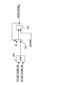
次に、本発明のアプリケーションの1例である、超音波流量計における時間測定について説明する。図14は超音波流量計の計測原理を説明する断面図である。超音波流量計は、超音波センサ102と超音波センサ103のそれぞれから超音波信号を送出して、超音波センサ102から超音波センサ103までの順方向(流体101が流れる方向)の超音波の伝搬時間FW1と、超音波センサ103から超音波センサ102までの逆方向の超音波の伝搬時間RV1とをそれぞれ求め、伝搬時間FW1とRV1の差分から、配管100を流れる流体101の流量を算出するものである。
Next, time measurement in an ultrasonic flow meter, which is an example of the application of the present invention, will be described. FIG. 14 is a cross-sectional view illustrating the measurement principle of the ultrasonic flow meter. The ultrasonic flow meter sends ultrasonic signals from each of the
図15は超音波センサ102から送信する超音波送信信号SS_FWと超音波センサ103で受信した超音波受信信号RS_FW、および超音波センサ103から送信する超音波送信信号SS_RVと超音波センサ103で受信した超音波受信信号RS_RVの波形例を示す図である。
FIG. 15 shows an ultrasonic transmission signal SS_FW transmitted from an
超音波流量計向けの時間計測では、1回の開始信号START(時間計測開始)に対して複数回の停止信号STOPの受け付けが可能であることが求められる。しかし、1回の時間計測に必要な処理時間が存在するため、連続で停止信号STOPを受け付け可能だとしても、2つの停止信号STOP間の最低間隔の制約が時間計測回路には必ず存在する。この制約を短くするためには、低速クロックLS_CLKの周波数を上げるという対応が最も容易であるが、このような対処は消費電力面で不利となる。 In the time measurement for the ultrasonic flow meter, it is required that the stop signal STOP can be accepted a plurality of times for one start signal START (time measurement start). However, since the processing time required for one time measurement exists, even if the stop signal STOP can be continuously received, the time measurement circuit always has a restriction on the minimum interval between the two stop signal STOPs. In order to shorten this restriction, it is easiest to increase the frequency of the low-speed clock LS_CLK, but such measures are disadvantageous in terms of power consumption.
そこで、本発明の第2、第3の実施例では、低速クロックLS_CLKの周波数を上げずに2つの停止信号STOP間の受け付け可能間隔を短くしている。上記のとおり、低速クロックLS_CLKの周波数が4MHzの場合、第2の実施例では、2つの停止信号STOP間の受け付け可能間隔は635ns、第3の実施例では、2つの停止信号STOP間の受け付け可能間隔は510nsである。 Therefore, in the second and third embodiments of the present invention, the acceptable interval between the two stop signals STOP is shortened without increasing the frequency of the low-speed clock LS_CLK. As described above, when the frequency of the low-speed clock LS_CLK is 4 MHz, the acceptable interval between the two stop signal STOPs is 635 ns in the second embodiment, and the acceptable interval between the two stop signal STOPs is possible in the third embodiment. The interval is 510 ns.
なお、第1〜第4の実施例では、RSフリップフロップ回路11を用いているが、これに限るものではなく、RSフリップフロップ回路11の代わりにDフリップフロップ回路を用いてもよい。Dフリップフロップ回路を用いる場合にも、クロックの変化とRESETの変化とが競合することは避けなければならない。RSフリップフロップ回路11の代わりにDフリップフロップ回路を用いる場合には、D入力を“1”に固定し、発振開始信号ROSC_STARTをクロック入力とし、発振停止信号ROSC_STOPをRESET入力とすればよい。
Although the RS flip-
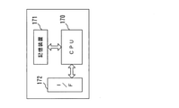
第1〜第4の実施例で説明した時間計測回路の時間算出回路17は、CPU(Central Processing Unit)、記憶装置及びインタフェースを備えたコンピュータと、これらのハードウェア資源を制御するプログラムによって実現することができる。このコンピュータの構成例を図16に示す。コンピュータは、CPU170と、記憶装置171と、インターフェース装置(以下、I/Fと略する)172とを備えている。I/F172には、高速カウンタ13とデコーダ14と低速カウンタ15とリングオシレータ型TDC制御回路2,2a,2bの出力(HS_CNT_EN)とが接続される。このようなコンピュータにおいて、本発明を実現させるためのプログラムは記憶装置171に格納される。CPU170は、記憶装置171に格納されたプログラムに従って第1〜第4の実施例で説明した処理を実行する。
The
本発明は、psecオーダーの時間を計測する技術に適用することができる。 The present invention can be applied to a technique for measuring time on the order of psec.
1…リングオシレータ型TDC、2,2a,2b,2c…リングオシレータ型TDC制御回路、10…OR回路、11…RSフリップフロップ回路、12…リングオシレータ、13…高速カウンタ、14…デコーダ、15…低速カウンタ、16…低速クロックイネーブル作成回路、17…時間算出回路、20,22,23,23c,24,26,28〜30,121−1〜121−(n+1)…Dフリップフロップ回路、21,120−1〜120−n,272,322…インバータ回路、25…発振停止信号生成回路、27,32…微分回路、31…XOR回路、33…検出信号生成回路、120,271,321…AND回路、270,320…バッファ回路。
1 ... Ring oscillator type TDC, 2,2a, 2b, 2c ... Ring oscillator type TDC control circuit, 10 ... OR circuit, 11 ... RS flip-flop circuit, 12 ... Ring oscillator, 13 ... High-speed counter, 14 ... Decoder, 15 ... Low speed counter, 16 ... low speed clock enable creation circuit, 17 ... time calculation circuit, 20, 22, 23, 23c, 24, 26, 28 to 30, 121-11 to 121- (n + 1) ... D flip-flop circuit, 21, 120-1 to 120-n, 272,322 ... Inverter circuit, 25 ... Oscillation stop signal generation circuit, 27,32 ... Differentiating circuit, 31 ... XOR circuit, 33 ... Detection signal generation circuit, 120, 271,321 ... AND
Claims (6)
時間計測の開始信号または停止信号の入力のタイミングであるSET入力のタイミングで有意となり、RESET入力のタイミングで無意となる発振許可信号を出力するように構成されたフリップフロップ回路と、
前記発振許可信号が有意の期間中に前記第1のクロックよりも高速な第2のクロックを生成するように構成された発振回路と、
前記第2のクロックを数えるように構成された第2のカウンタと、
前記第1のカウンタの計数結果と前記第2のカウンタの計数結果とを基に前記開始信号の入力から前記停止信号の入力までの時間間隔を算出するように構成された時間算出回路と、
前記開始信号および前記停止信号と前記第1のクロックとから生成した発振停止信号を、前記フリップフロップ回路に前記RESET入力として与えるように構成された制御回路とを備え、
前記制御回路は、前記SET入力のタイミングから前記RESET入力のタイミングまでの期間が前記第1のクロックの1周期以上3周期以下の期間となる前記発振停止信号を生成することを特徴とする時間計測回路。 A first counter configured to count the first clock input from the outside,
A flip-flop circuit configured to output an oscillation permission signal that becomes significant at the timing of SET input, which is the timing of input of the start signal or stop signal of time measurement, and becomes unintentional at the timing of REST input.
An oscillation circuit configured to generate a second clock faster than the first clock during a significant period of time for the oscillation permission signal.
A second counter configured to count the second clock,
A time calculation circuit configured to calculate the time interval from the input of the start signal to the input of the stop signal based on the count result of the first counter and the count result of the second counter.
A control circuit configured to give an oscillation stop signal generated from the start signal, the stop signal, and the first clock to the flip-flop circuit as the RESET input is provided.
The control circuit is characterized in that it generates the oscillation stop signal in which the period from the timing of the SET input to the timing of the SET input is a period of 1 cycle or more and 3 cycles or less of the first clock. circuit.
前記制御回路は、
前記開始信号および前記停止信号の入力の度に反転する検出信号を出力するように構成された検出信号生成回路と、
前記検出信号を、前記第1のクロックの1クロック分遅延させた第1の遅延信号を出力するように構成された第1のDフリップフロップ回路と、
前記第1の遅延信号を、前記第1のクロックの1/2クロック分遅延させた第2の遅延信号を出力するように構成された第2のDフリップフロップ回路と、
前記第2の遅延信号を、前記第1のクロックの1/2クロック分遅延させた第3の遅延信号を出力するように構成された第3のDフリップフロップ回路と、
前記第3の遅延信号が入力されたタイミングで有意となり、次の第1のクロックが入力されたタイミングで無意となる前記発振停止信号を生成するように構成された発振停止信号生成回路と、
前記発振停止信号を、前記第1のクロックの1/2クロック分遅延させた取り込み許可信号を出力するように構成された第4のDフリップフロップ回路とから構成され、
前記時間算出回路は、前記取り込み許可信号が有意となるタイミングで前記第2のカウンタの計数結果を取り込むことを特徴とする時間計測回路。 In the time measurement circuit according to claim 1,
The control circuit is
A detection signal generation circuit configured to output a detection signal that is inverted each time the start signal and the stop signal are input.
A first D flip-flop circuit configured to output a first delay signal obtained by delaying the detection signal by one clock of the first clock.
A second D flip-flop circuit configured to output a second delay signal obtained by delaying the first delay signal by 1/2 clock of the first clock.
A third D flip-flop circuit configured to output a third delay signal obtained by delaying the second delay signal by 1/2 clock of the first clock.
An oscillation stop signal generation circuit configured to generate the oscillation stop signal that becomes significant at the timing when the third delay signal is input and becomes unintentional at the timing when the next first clock is input.
It is composed of a fourth D flip-flop circuit configured to output an capture permission signal obtained by delaying the oscillation stop signal by 1/2 clock of the first clock.
The time calculation circuit is a time measurement circuit characterized in that the count result of the second counter is captured at a timing when the capture permission signal becomes significant.
前記第2のカウンタは、前記発振停止信号が有意から無意へと変わるタイミングで計数結果を0に初期化することを特徴とする時間計測回路。 In the time measurement circuit according to claim 1 or 2.
The second counter is a time measurement circuit characterized in that the counting result is initialized to 0 at the timing when the oscillation stop signal changes from significant to unexpected.
前記制御回路は、前記取り込み許可信号が有意となるタイミングで前記取り込み許可信号を微分した結果をリセット信号として出力するように構成された微分回路をさらに備え、
前記第2のカウンタは、前記リセット信号が有意となるタイミングで計数結果を0に初期化することを特徴とする時間計測回路。 In the time measurement circuit according to claim 2,
The control circuit further includes a differentiating circuit configured to output the result of differentiating the capture permission signal as a reset signal at the timing when the capture permission signal becomes significant.
The second counter is a time measurement circuit characterized in that the counting result is initialized to 0 at the timing when the reset signal becomes significant.
前記制御回路は、
前記開始信号および前記停止信号の入力の度に反転する検出信号を出力するように構成された検出信号生成回路と、
前記検出信号を、前記第1のクロックの1/2クロック分遅延させた第1の遅延信号を出力するように構成された第1のDフリップフロップ回路と、
前記第1の遅延信号を、前記第1のクロックの1/2クロック分遅延させた第2の遅延信号を出力するように構成された第2のDフリップフロップ回路と、
前記第2の遅延信号を、前記第1のクロックの1/2クロック分遅延させた第3の遅延信号を出力するように構成された第3のDフリップフロップ回路と、
前記第2の遅延信号と前記第3の遅延信号との排他的論理和の結果を、前記発振停止信号および取り込み許可信号として出力するように構成された排他的論理和回路と、
前記取り込み許可信号が無意となるタイミングで前記取り込み許可信号を微分した結果をリセット信号として出力するように構成された微分回路とから構成され、
前記時間算出回路は、前記取り込み許可信号が有意となるタイミングで前記第2のカウンタの計数結果を取り込み、
前記第2のカウンタは、前記リセット信号が有意となるタイミングで計数結果を0に初期化することを特徴とする時間計測回路。 In the time measurement circuit according to claim 1,
The control circuit is
A detection signal generation circuit configured to output a detection signal that is inverted each time the start signal and the stop signal are input.
A first D flip-flop circuit configured to output a first delay signal obtained by delaying the detection signal by 1/2 clock of the first clock.
A second D flip-flop circuit configured to output a second delay signal obtained by delaying the first delay signal by 1/2 clock of the first clock.
A third D flip-flop circuit configured to output a third delay signal obtained by delaying the second delay signal by 1/2 clock of the first clock.
An exclusive OR circuit configured to output the result of the exclusive OR of the second delay signal and the third delay signal as the oscillation stop signal and the capture permission signal.
It is composed of a differentiating circuit configured to output the result of differentiating the capture permission signal as a reset signal at the timing when the capture permission signal becomes unintentional.
The time calculation circuit captures the counting result of the second counter at the timing when the capture permission signal becomes significant.
The second counter is a time measurement circuit characterized in that the counting result is initialized to 0 at the timing when the reset signal becomes significant.
前記制御回路は、
前記開始信号および前記停止信号の入力の度に反転する検出信号を出力するように構成された検出信号生成回路と、
前記検出信号を、前記第1のクロックの1クロック分遅延させた第1の遅延信号を出力するように構成された第1のDフリップフロップ回路と、
前記第1の遅延信号を、前記第1のクロックの1クロック分遅延させた第2の遅延信号を出力するように構成された第2のDフリップフロップ回路と、
前記第2の遅延信号を、前記第1のクロックの1クロック分遅延させた第3の遅延信号を出力するように構成された第3のDフリップフロップ回路と、
前記第3の遅延信号が入力されたタイミングで有意となり、次の第1のクロックが入力されたタイミングで無意となる前記発振停止信号を生成するように構成された発振停止信号生成回路と、
前記発振停止信号を、前記第1のクロックの1/2クロック分遅延させた取り込み許可信号を出力するように構成された第4のDフリップフロップ回路とから構成され、
前記時間算出回路は、前記取り込み許可信号が有意となるタイミングで前記第2のカウンタの計数結果を取り込むことを特徴とする時間計測回路。 In the time measurement circuit according to claim 1,
The control circuit is
A detection signal generation circuit configured to output a detection signal that is inverted each time the start signal and the stop signal are input.
A first D flip-flop circuit configured to output a first delay signal obtained by delaying the detection signal by one clock of the first clock.
A second D flip-flop circuit configured to output a second delay signal obtained by delaying the first delay signal by one clock of the first clock.
A third D flip-flop circuit configured to output a third delay signal obtained by delaying the second delay signal by one clock of the first clock.
An oscillation stop signal generation circuit configured to generate the oscillation stop signal that becomes significant at the timing when the third delay signal is input and becomes unintentional at the timing when the next first clock is input.
It is composed of a fourth D flip-flop circuit configured to output an capture permission signal obtained by delaying the oscillation stop signal by 1/2 clock of the first clock.
The time calculation circuit is a time measurement circuit characterized in that the count result of the second counter is captured at a timing when the capture permission signal becomes significant.
Priority Applications (1)
| Application Number | Priority Date | Filing Date | Title |
|---|---|---|---|
| JP2018003183A JP6989397B2 (en) | 2018-01-12 | 2018-01-12 | Time measurement circuit |
Applications Claiming Priority (1)
| Application Number | Priority Date | Filing Date | Title |
|---|---|---|---|
| JP2018003183A JP6989397B2 (en) | 2018-01-12 | 2018-01-12 | Time measurement circuit |
Publications (2)
| Publication Number | Publication Date |
|---|---|
| JP2019124478A JP2019124478A (en) | 2019-07-25 |
| JP6989397B2 true JP6989397B2 (en) | 2022-01-05 |
Family
ID=67398595
Family Applications (1)
| Application Number | Title | Priority Date | Filing Date |
|---|---|---|---|
| JP2018003183A Active JP6989397B2 (en) | 2018-01-12 | 2018-01-12 | Time measurement circuit |
Country Status (1)
| Country | Link |
|---|---|
| JP (1) | JP6989397B2 (en) |
Families Citing this family (1)
| Publication number | Priority date | Publication date | Assignee | Title |
|---|---|---|---|---|
| CN114675525B (en) * | 2021-09-30 | 2022-09-02 | 绍兴圆方半导体有限公司 | Time-to-digital converter and clock synchronization system |
Family Cites Families (4)
| Publication number | Priority date | Publication date | Assignee | Title |
|---|---|---|---|---|
| JPS6295487A (en) * | 1985-10-22 | 1987-05-01 | Yokogawa Electric Corp | Time width measuring instrument |
| US5027298A (en) * | 1989-06-29 | 1991-06-25 | Genrad, Inc. | Low-dead-time interval timer |
| JPH07209447A (en) * | 1994-01-21 | 1995-08-11 | Advantest Corp | Elapsed time measuring circuit |
| JP6299516B2 (en) * | 2014-08-05 | 2018-03-28 | 株式会社デンソー | Time measurement circuit |
-
2018
- 2018-01-12 JP JP2018003183A patent/JP6989397B2/en active Active
Also Published As
| Publication number | Publication date |
|---|---|
| JP2019124478A (en) | 2019-07-25 |
Similar Documents
| Publication | Publication Date | Title |
|---|---|---|
| TWI644516B (en) | A circuit delay monitoring apparatus and method | |
| US8732509B2 (en) | Timing synchronization circuit with loop counter | |
| US7804290B2 (en) | Event-driven time-interval measurement | |
| US8081013B1 (en) | Digital phase and frequency detector | |
| US8779816B2 (en) | Low area all digital delay-locked loop insensitive to reference clock duty cycle and jitter | |
| WO2013069173A1 (en) | Digital time difference converter | |
| JP6433955B2 (en) | High resolution time-to-digital converter | |
| Polzer et al. | An approach for efficient metastability characterization of FPGAs through the designer | |
| JP2011159873A (en) | Semiconductor integrated circuit and voltage controller therewith | |
| TWI768384B (en) | Circuit and method for generating pulse output | |
| JP6989397B2 (en) | Time measurement circuit | |
| US10177747B2 (en) | High resolution capture | |
| US8436604B2 (en) | Measuring apparatus, parallel measuring apparatus, testing apparatus and electronic device | |
| KR20190063492A (en) | Time-to-digital converter supporting run-time calibration | |
| CN102230826B (en) | Signal processing method for heterodyne interferometer | |
| Angeli et al. | A scalable fully synthesized phase-to-digital converter for phase and duty-cycle measurement of high-speed clocks | |
| KR102655138B1 (en) | time measurement circuit | |
| Chen et al. | A coarse-fine time-to-digital converter | |
| JPS62147371A (en) | Pulse width meter | |
| JP3864583B2 (en) | Variable delay circuit | |
| JP7393300B2 (en) | time measurement circuit | |
| Russo et al. | FPGA-based Trigger-Synchronizer for low Frame-Jitter Signal Generation | |
| Perko et al. | A programmable delay line | |
| Russo et al. | FPGA-Based Clock Phase Alignment Circuit for Frame Jitter Reduction | |
| JP2005201709A (en) | Time measuring circuit |
Legal Events
| Date | Code | Title | Description |
|---|---|---|---|
| A621 | Written request for application examination |
Free format text: JAPANESE INTERMEDIATE CODE: A621 Effective date: 20200911 |
|
| A977 | Report on retrieval |
Free format text: JAPANESE INTERMEDIATE CODE: A971007 Effective date: 20210719 |
|
| A131 | Notification of reasons for refusal |
Free format text: JAPANESE INTERMEDIATE CODE: A131 Effective date: 20210810 |
|
| A521 | Request for written amendment filed |
Free format text: JAPANESE INTERMEDIATE CODE: A523 Effective date: 20210910 |
|
| TRDD | Decision of grant or rejection written | ||
| A01 | Written decision to grant a patent or to grant a registration (utility model) |
Free format text: JAPANESE INTERMEDIATE CODE: A01 Effective date: 20211109 |
|
| A61 | First payment of annual fees (during grant procedure) |
Free format text: JAPANESE INTERMEDIATE CODE: A61 Effective date: 20211202 |
|
| R150 | Certificate of patent or registration of utility model |
Ref document number: 6989397 Country of ref document: JP Free format text: JAPANESE INTERMEDIATE CODE: R150 |
|
| R250 | Receipt of annual fees |
Free format text: JAPANESE INTERMEDIATE CODE: R250 |
|
| R250 | Receipt of annual fees |
Free format text: JAPANESE INTERMEDIATE CODE: R250 |