JP6988198B2 - Vehicle lighting - Google Patents

Vehicle lighting Download PDF

Info

Publication number
JP6988198B2
JP6988198B2 JP2017126055A JP2017126055A JP6988198B2 JP 6988198 B2 JP6988198 B2 JP 6988198B2 JP 2017126055 A JP2017126055 A JP 2017126055A JP 2017126055 A JP2017126055 A JP 2017126055A JP 6988198 B2 JP6988198 B2 JP 6988198B2
Authority
JP
Japan
Prior art keywords
light source
source unit
light
vehicle
bracket
Prior art date
Legal status (The legal status is an assumption and is not a legal conclusion. Google has not performed a legal analysis and makes no representation as to the accuracy of the status listed.)
Active
Application number
JP2017126055A
Other languages
Japanese (ja)
Other versions
JP2019009065A (en
Inventor
央充 大倉
和昭 山本
Current Assignee (The listed assignees may be inaccurate. Google has not performed a legal analysis and makes no representation or warranty as to the accuracy of the list.)
Ichikoh Industries Ltd
Original Assignee
Ichikoh Industries Ltd
Priority date (The priority date is an assumption and is not a legal conclusion. Google has not performed a legal analysis and makes no representation as to the accuracy of the date listed.)
Filing date
Publication date
Application filed by Ichikoh Industries Ltd filed Critical Ichikoh Industries Ltd
Priority to JP2017126055A priority Critical patent/JP6988198B2/en
Publication of JP2019009065A publication Critical patent/JP2019009065A/en
Application granted granted Critical
Publication of JP6988198B2 publication Critical patent/JP6988198B2/en
Active legal-status Critical Current
Anticipated expiration legal-status Critical

Links

Images

Landscapes

  • Non-Portable Lighting Devices Or Systems Thereof (AREA)

Description

本発明は、車両用灯具に関する。 The present invention relates to a vehicle lamp.

例えばロービームのパターンを照射する光源ユニットと、ハイビームのパターンを照射する光源ユニットとを備える車両用灯具等のように、複数の光源ユニットを有する車両用灯具が知られている(例えば、特許文献1参照)。 For example, a vehicle lighting device having a plurality of light source units is known, such as a vehicle lighting device including a light source unit that irradiates a low beam pattern and a light source unit that irradiates a high beam pattern (for example, Patent Document 1). reference).

特開2012−38609号公報Japanese Unexamined Patent Publication No. 2012-38609

上記のような車両用灯具は、複数の光源ユニットが例えばブラケットに支持された状態でハウジングに収容される。この場合、複数の光源ユニット及びブラケットをハウジング内にコンパクトに配置させることが求められる。 A vehicle lamp as described above is housed in a housing in a state where a plurality of light source units are supported by, for example, brackets. In this case, it is required to compactly arrange a plurality of light source units and brackets in the housing.

本発明は、上記に鑑みてなされたものであり、複数の光源ユニット及びブラケットをコンパクトに配置させることが可能な車両用灯具を提供することを目的とする。 The present invention has been made in view of the above, and an object of the present invention is to provide a vehicle lamp in which a plurality of light source units and brackets can be compactly arranged.

本発明に係る車両用灯具は、車両搭載状態における前後方向である一方向の前方に光を照射する第1光源ユニットと、前記一方向の前方に光を照射する光照射部を有する第2光源ユニットと、前記第1光源ユニット及び前記第2光源ユニットを支持し、前記一方向の前方から見て前記第1光源ユニットを内側に囲う環状のブラケットと、を備え、前記光照射部は、前記一方向の前方から見て、前記ブラケットによって囲まれる領域の外側に配置される。 The vehicle lighting equipment according to the present invention has a first light source unit that irradiates light in the front in one direction, which is the front-rear direction in the vehicle-mounted state, and a second light source having a light irradiation unit that irradiates light in the front in the one direction. The unit is provided with an annular bracket that supports the first light source unit and the second light source unit and surrounds the first light source unit inward when viewed from the front in one direction, and the light irradiation unit is the light irradiation unit. Seen from the front in one direction, it is located outside the area enclosed by the bracket.

上記の車両用灯具において、前記光照射部は、リフレクタであってもよい。 In the above-mentioned vehicle lighting equipment, the light irradiation unit may be a reflector.

上記の車両用灯具において、前記ブラケットは、前記一方向の後方に凹状に湾曲した湾曲部を有し、前記第2光源ユニットは、前記湾曲部によって形成される凹部に配置されてもよい。 In the vehicle lamp, the bracket may have a concavely curved portion rearward in one direction, and the second light source unit may be arranged in the concave portion formed by the curved portion.

上記の車両用灯具において、前記第2光源ユニットは、前記光照射部に向けて光を出射する半導体型光源と、前記半導体型光源及び前記光照射部を支持するヒートシンクとを有し、前記ヒートシンクは、前記凹部に配置され、前記ブラケットは、前記湾曲部から前記一方向の後方に突出する突出片を有してもよい。 In the above-mentioned vehicle lamp, the second light source unit has a semiconductor type light source that emits light toward the light irradiation unit, the semiconductor type light source, and a heat sink that supports the light irradiation unit, and the heat sink. Is disposed in the recess, the bracket may have a protruding piece projecting rearward in one direction from the curved portion.

上記の車両用灯具は、前記第1光源ユニット、前記第2光源ユニット及び前記ブラケットを収容するハウジングを更に備え、前記ハウジングは、前記突出片を収容して前記突出片の上方及び下方への移動を規制する収容部を有してもよい。 The vehicle lighting fixture further includes a housing for accommodating the first light source unit, the second light source unit, and the bracket, and the housing accommodates the projecting piece and moves upward and downward of the projecting piece. It may have a containment unit that regulates.

上記の車両用灯具において、前記ブラケットは、車両搭載状態で水平面に平行な仮想直線軸の軸回り方向に回動可能に設けられ、前記突出片は、車両搭載状態で前記仮想直線軸と等しい高さ位置に配置されてもよい。 In the above-mentioned vehicle lighting equipment, the bracket is provided so as to be rotatable in the axial direction of a virtual linear axis parallel to a horizontal plane in the vehicle-mounted state, and the projecting piece has a height equal to the virtual linear axis in the vehicle-mounted state. It may be placed in a parallel position.

上記の車両用灯具において、前記光照射部は、前記一方向の前方から見て、前記ブラケットに対して車両搭載状態における上方に配置されてもよい。 In the above-mentioned vehicle lighting equipment, the light irradiation unit may be arranged above the bracket in the vehicle-mounted state when viewed from the front in the one direction.

上記の車両用灯具において、前記第1光源ユニットは、光を照射する投影レンズを有し、前記光照射部は、前記一方向の前方から見て、前記投影レンズの車両搭載状態における斜め上方に配置されてもよい。 In the above-mentioned vehicle lighting equipment, the first light source unit has a projection lens that irradiates light, and the light irradiation unit is obliquely upward in the vehicle-mounted state of the projection lens when viewed from the front in one direction. It may be arranged.

本発明によれば、複数の光源ユニット及びブラケットをコンパクトに配置させることが可能な車両用灯具を提供することができる。 According to the present invention, it is possible to provide a vehicle lighting fixture capable of compactly arranging a plurality of light source units and brackets.

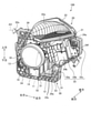
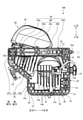
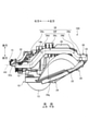
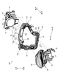
図1は、本実施形態に係る車両用灯具の一例を示す斜視図である。FIG. 1 is a perspective view showing an example of a vehicle lamp according to the present embodiment. 図2は、本実施形態に係る車両用灯具の一例を示す斜視図である。FIG. 2 is a perspective view showing an example of a vehicle lamp according to the present embodiment. 図3は、車両用灯具を前方から見た状態を示す図(正面図)である。FIG. 3 is a view (front view) showing a state in which the vehicle lamp is viewed from the front. 図4は、車両用灯具を後方から見た状態を示す図(背面図)である。FIG. 4 is a view (rear view) showing a state in which the vehicle lamp is viewed from the rear. 図5は、車両用灯具を上方から見た状態を示す図(平面図)である。FIG. 5 is a view (plan view) showing a state in which the vehicle lamp is viewed from above. 図6は、ブラケットの一部を拡大して示す図である。FIG. 6 is an enlarged view showing a part of the bracket. 図7は、本実施形態に係る車両用灯具の分解斜視図である。FIG. 7 is an exploded perspective view of a vehicle lamp according to the present embodiment. 図8は、図3におけるA−A断面に沿った構成を示す図である。FIG. 8 is a diagram showing a configuration along a cross section taken along the line AA in FIG.

以下、本発明に係る車両用灯具の実施形態を図面に基づいて説明する。なお、この実施形態によりこの発明が限定されるものではない。また、下記実施形態における構成要素には、当業者が置換可能かつ容易なもの、あるいは実質的に同一のものが含まれる。 Hereinafter, embodiments of the vehicle lamp according to the present invention will be described with reference to the drawings. The present invention is not limited to this embodiment. In addition, the components in the following embodiments include those that can be easily replaced by those skilled in the art, or those that are substantially the same.

以下の説明において、前後方向、上下方向、左右方向の各方向は、水平面に平行な面に配置された車両に車両用灯具が取り付けられた状態(車両搭載状態)における方向であって、運転席から正面を見た場合における方向を示す。したがって、本実施形態では、上下方向は鉛直方向であり、前後方向(一方向)及び左右方向は水平面に平行な方向(水平方向)となる。 In the following description, each of the front-rear direction, the vertical direction, and the left-right direction is the direction in which the vehicle lighting equipment is attached to the vehicle arranged on the plane parallel to the horizontal plane (vehicle-mounted state), and is the direction in which the driver's seat is mounted. The direction when looking at the front from the front is shown. Therefore, in the present embodiment, the vertical direction is the vertical direction, and the front-back direction (one direction) and the left-right direction are the directions parallel to the horizontal plane (horizontal direction).

図1及び図2は、本実施形態に係る車両用灯具100の一例を示す斜視図である。図1は左前方から見た状態、図2は左後方から見た状態を示している。図3は、車両用灯具100を前方から見た状態を示す図(正面図)である。図4は、車両用灯具100を後方から見た状態を示す図(背面図)である。図5は、車両用灯具100を上方から見た状態を示す図(平面図)である。 1 and 2 are perspective views showing an example of a vehicle lamp 100 according to the present embodiment. FIG. 1 shows a state viewed from the front left, and FIG. 2 shows a state viewed from the rear left. FIG. 3 is a view (front view) showing a state in which the vehicle lamp 100 is viewed from the front. FIG. 4 is a view (rear view) showing a state in which the vehicle lamp 100 is viewed from the rear. FIG. 5 is a view (plan view) showing a state in which the vehicle lamp 100 is viewed from above.

図1から図5に示すように、車両用灯具100は、例えば車両の前照灯として用いられる。車両用灯具100は、車両の前部において、左右に1つずつ配置される。本実施形態では、車両の前部左側に配置された車両用灯具100を例に挙げて説明する。なお、車両の前部右側に配置された車両用灯具は、本実施形態において説明する車両用灯具100に対して、左右対称の構成である。車両用灯具100は、第1光源ユニット10と、第2光源ユニット20と、ブラケット30とを備えている。 As shown in FIGS. 1 to 5, the vehicle lighting fixture 100 is used, for example, as a vehicle headlight. The vehicle lighting equipment 100 is arranged one on each side in the front part of the vehicle. In the present embodiment, a vehicle lamp 100 arranged on the left side of the front part of the vehicle will be described as an example. The vehicle lighting fixture arranged on the right side of the front portion of the vehicle has a symmetrical configuration with respect to the vehicle lighting fixture 100 described in the present embodiment. The vehicle lamp 100 includes a first light source unit 10, a second light source unit 20, and a bracket 30.

第1光源ユニット10は、ロービームのパターンを例えば車両搭載状態の前方に照射する。第1光源ユニット10は、第1光源11と、リフレクタ12と、投影レンズ13と、ヒートシンク14と、コネクタ15とを有している。 The first light source unit 10 irradiates the low beam pattern, for example, in front of the vehicle mounted state. The first light source unit 10 has a first light source 11, a reflector 12, a projection lens 13, a heat sink 14, and a connector 15.

第1光源11は、本実施形態において、例えばLED(Light Emitting Diode)やOEL(Organic Electroluminescence)、OLED(Organic Light Emitting Diode)などの半導体型光源である。第1光源11は、発光面からランバーシアン分布を形成するように光を出射する。第1光源11は、不図示の回路基板等に実装される。回路基板には、コネクタ15及び配線を介して電源が供給される。 In the present embodiment, the first light source 11 is a semiconductor type light source such as an LED (Light Emitting Diode), an OEL (Organic Electroluminescence), or an OLED (Organic Light Emitting Diode). The first light source 11 emits light from the light emitting surface so as to form a Lambersian distribution. The first light source 11 is mounted on a circuit board or the like (not shown). Power is supplied to the circuit board via the connector 15 and wiring.

リフレクタ12は、第1光源11の鉛直方向の上方に配置される。リフレクタ12は、例えばヒートシンク14に支持される。リフレクタ12は、内側に反射面を有している。反射面は、第1光源11からの光を車両の前方に反射する。反射面は、例えば楕円を基調とする自由曲面からなる反射面、あるいは、回転楕円面からなる反射面とすることができる。 The reflector 12 is arranged above the first light source 11 in the vertical direction. The reflector 12 is supported by, for example, a heat sink 14. The reflector 12 has a reflective surface inside. The reflecting surface reflects the light from the first light source 11 to the front of the vehicle. The reflecting surface can be, for example, a reflecting surface having a free curved surface based on an ellipse, or a reflecting surface having a spheroidal surface.

投影レンズ13は、リフレクタ12に対して車両の前方に配置される。投影レンズ13は、ヒートシンク14に支持される。投影レンズ13は、レンズ焦点(図示せず)と、レンズ軸(図示せず)とを有する。投影レンズ13のレンズ焦点は、リフレクタ12の基準焦点と一致もしくはほぼ一致する。投影レンズ13のレンズ軸は、リフレクタ12の基準光軸と一致もしくはほぼ一致する。投影レンズ13は、反射面12aからの反射光であって、投影レンズ13とリフレクタ12との間に配置される不図示のシェードにより遮蔽された反射光以外の反射光を車両の前方に照射する。 The projection lens 13 is arranged in front of the vehicle with respect to the reflector 12. The projection lens 13 is supported by the heat sink 14. The projection lens 13 has a lens focal point (not shown) and a lens axis (not shown). The lens focal point of the projection lens 13 coincides with or substantially coincides with the reference focal point of the reflector 12. The lens axis of the projection lens 13 coincides with or substantially coincides with the reference optical axis of the reflector 12. The projection lens 13 is the reflected light from the reflecting surface 12a, and irradiates the front of the vehicle with reflected light other than the reflected light shielded by a shade (not shown) arranged between the projection lens 13 and the reflector 12. ..

ヒートシンク14は、第1光源11で生じる熱を外部に放熱する。ヒートシンク14は、例えば金型成形等を用いて製造可能である。ヒートシンク14は、基部14aと、複数のフィン14bと、固定片14c、14d、14e(図4参照)とを有する。基部14aは、板状であり、第1光源11を支持する。複数のフィン14bは、板状であり、基部14aから下方に向けて延びている。固定片14c、14d、14eは、後述するように、基部14aの左右両端に配置され、ネジ等の固定部材を介してブラケット30の後面側に固定される(図4参照)。 The heat sink 14 dissipates heat generated by the first light source 11 to the outside. The heat sink 14 can be manufactured by using, for example, mold molding or the like. The heat sink 14 has a base 14a, a plurality of fins 14b, and fixing pieces 14c, 14d, 14e (see FIG. 4). The base portion 14a has a plate shape and supports the first light source 11. The plurality of fins 14b are plate-shaped and extend downward from the base 14a. As will be described later, the fixing pieces 14c, 14d, and 14e are arranged at both left and right ends of the base portion 14a, and are fixed to the rear surface side of the bracket 30 via fixing members such as screws (see FIG. 4).

第2光源ユニット20は、ハイビームのパターンを例えば車両搭載状態の前方に照射する。第2光源ユニット20は、第2光源21と、リフレクタ(光照射部)22と、ヒートシンク24と、コネクタ25と、を有している。 The second light source unit 20 irradiates the high beam pattern, for example, in front of the vehicle mounted state. The second light source unit 20 has a second light source 21, a reflector (light irradiation unit) 22, a heat sink 24, and a connector 25.

第2光源21は、本実施形態において、第1光源11と同様に、例えばLEDやOEL、OLED等の半導体型光源である。第2光源21は、発光面からランバーシアン分布を形成するように光を出射する。第2光源21は、不図示の回路基板等に実装される。回路基板には、コネクタ25及び配線を介して電源が供給される。 In the present embodiment, the second light source 21 is a semiconductor type light source such as an LED, an OEL, or an OLED, like the first light source 11. The second light source 21 emits light from the light emitting surface so as to form a Lambersian distribution. The second light source 21 is mounted on a circuit board or the like (not shown). Power is supplied to the circuit board via the connector 25 and the wiring.

リフレクタ22は、第2光源21からの光を前方に照射する光照射部である。リフレクタ22は、第2光源21からの光の進行方向上に配置される。リフレクタ22は、ヒートシンク24に支持される。リフレクタ22は、反射面22aを有している。反射面22aは、第2光源21からの光を車両の前方に反射する。反射面22aは、例えば楕円を基調とする自由曲面からなる反射面、あるいは、回転楕円面からなる反射面とすることができる。 The reflector 22 is a light irradiation unit that irradiates the light from the second light source 21 forward. The reflector 22 is arranged in the traveling direction of the light from the second light source 21. The reflector 22 is supported by the heat sink 24. The reflector 22 has a reflecting surface 22a. The reflecting surface 22a reflects the light from the second light source 21 to the front of the vehicle. The reflecting surface 22a can be, for example, a reflecting surface made of a free curved surface based on an ellipse, or a reflecting surface made of a spheroidal surface.

ヒートシンク24は、第2光源21及びリフレクタ22を支持し、第2光源21で生じる熱を外部に放熱する。ヒートシンク24は、支持部24aと、壁部24bと、フィン24c、24dと、固定片24e、24f、24gとを有する。ヒートシンク24は、例えば金型成形等により製造可能である。 The heat sink 24 supports the second light source 21 and the reflector 22, and dissipates the heat generated by the second light source 21 to the outside. The heat sink 24 has a support portion 24a, a wall portion 24b, fins 24c and 24d, and fixed pieces 24e, 24f and 24g. The heat sink 24 can be manufactured, for example, by molding or the like.

支持部24aは、例えば板状であり、第2光源21及びリフレクタ22を支持する。壁部24bは、支持部24aの下面に配置され、例えばリフレクタ22からの光の出射方向に直交して配置される。フィン24c、24dは、例えば板状である。フィン24cは、壁部24bから前方に向けて延びている。フィン24dは、壁部24bから後方に向けて延びている。壁部24bから後方に向けて延びるフィン24dは、後述するブラケット30の上部フレーム34の下側から後方に突出する。フィン24c、24dの上下方向の寸法及び前後方向(突出方向)の寸法については、図示された構成に限定されず、適宜変更等してもよい。 The support portion 24a has, for example, a plate shape and supports the second light source 21 and the reflector 22. The wall portion 24b is arranged on the lower surface of the support portion 24a, and is arranged, for example, orthogonal to the emission direction of light from the reflector 22. The fins 24c and 24d are, for example, plate-shaped. The fin 24c extends forward from the wall portion 24b. The fin 24d extends rearward from the wall portion 24b. The fins 24d extending rearward from the wall portion 24b project rearward from the lower side of the upper frame 34 of the bracket 30, which will be described later. The dimensions of the fins 24c and 24d in the vertical direction and the dimensions in the front-rear direction (protruding direction) are not limited to the illustrated configuration, and may be appropriately changed.

固定片24eは、壁部24bから下方に突出している。固定片24fは、壁部24bから左方に突出している。固定片24gは、基部24aから右方に突出している。固定片24e、24f、24gは、後述するように、ネジ等の固定部材を介してブラケット30の前面側に固定される(図3参照)。 The fixed piece 24e projects downward from the wall portion 24b. The fixed piece 24f projects to the left from the wall portion 24b. The fixed piece 24g projects to the right from the base 24a. The fixing pieces 24e, 24f, and 24g are fixed to the front surface side of the bracket 30 via fixing members such as screws, as will be described later (see FIG. 3).

第2光源ユニット20は、全体が下部から上部にかけて右側に傾斜した状態で配置される。このため、第2光源ユニット20では、第2光源21の発光面が右斜め上方を向くように水平方向に対して傾いた状態で配置される。したがって、第2光源21から出射する光は、右斜め上方に進行する。リフレクタ22は、第2光源21から右斜め上方に進行する光を前方に向けて反射するように位置及び姿勢が設定される。 The second light source unit 20 is arranged in a state of being inclined to the right from the lower part to the upper part as a whole. Therefore, in the second light source unit 20, the light emitting surface of the second light source 21 is arranged in a state of being tilted with respect to the horizontal direction so as to face diagonally upward to the right. Therefore, the light emitted from the second light source 21 travels diagonally upward to the right. The position and orientation of the reflector 22 are set so as to reflect the light traveling diagonally upward to the right from the second light source 21 toward the front.

このように第2光源ユニット20を傾けて配置することにより、当該第2光源ユニット20は、リフレクタ22が右方つまり投影レンズ13側にずれた状態で配置され、ヒートシンク24が左方、つまり投影レンズ13側とは反対側にずれた状態で配置される。このため、リフレクタ22を投影レンズ13に近づけて配置することが可能となり、省スペース化を図ることができる。なお、第2光源ユニット20は、鉛直方向に対して傾いていなくてもよい。 By arranging the second light source unit 20 at an angle in this way, the second light source unit 20 is arranged with the reflector 22 shifted to the right, that is, toward the projection lens 13, and the heat sink 24 is arranged to the left, that is, the projection. It is arranged so as to be offset to the side opposite to the lens 13 side. Therefore, the reflector 22 can be arranged close to the projection lens 13, and space can be saved. The second light source unit 20 does not have to be tilted with respect to the vertical direction.

ブラケット30は、第1光源ユニット10及び第2光源ユニット20を支持する。ブラケット30は、車両搭載状態における前方から見て、第1光源ユニット10を内側に囲う環状に形成される。ブラケット30は、外枠部51と、内枠部52と、仕切り部53と、環状リブ部54、55とを有する。 The bracket 30 supports the first light source unit 10 and the second light source unit 20. The bracket 30 is formed in an annular shape that surrounds the first light source unit 10 inward when viewed from the front in the vehicle-mounted state. The bracket 30 has an outer frame portion 51, an inner frame portion 52, a partition portion 53, and annular rib portions 54 and 55.

外枠部51は、環状に形成され、ブラケット30の外周面を構成する。内枠部52は、環状に形成され、ブラケット30の内周面を構成する。仕切り部53は、外枠部51と内枠部52との間に配置され、外枠部51と内枠部52とで挟まれた空間を前後に仕切っている。環状リブ部54は、仕切り部53の前面に配置され、例えば正六角形状の複数の環状リブ同士が連結された構成を有する。環状リブ部55は、仕切り部53の後面に配置され、例えば正六角形状の複数の環状リブ同士が連結された構成を有する。環状リブ部54及び環状リブ部55が設けられることにより、仕切り部53ひいてはブラケット30が補強される。外枠部51、内枠部52、仕切り部54及び環状リブ部54、55は、それぞれPBT−2(ポリブチレンテレフタレート)等の樹脂により形成されている。 The outer frame portion 51 is formed in an annular shape and constitutes the outer peripheral surface of the bracket 30. The inner frame portion 52 is formed in an annular shape and constitutes the inner peripheral surface of the bracket 30. The partition portion 53 is arranged between the outer frame portion 51 and the inner frame portion 52, and partitions the space sandwiched between the outer frame portion 51 and the inner frame portion 52 back and forth. The annular rib portion 54 is arranged on the front surface of the partition portion 53, and has a structure in which a plurality of annular ribs having a regular hexagonal shape are connected to each other, for example. The annular rib portion 55 is arranged on the rear surface of the partition portion 53, and has a structure in which a plurality of annular ribs having a regular hexagonal shape are connected to each other, for example. By providing the annular rib portion 54 and the annular rib portion 55, the partition portion 53 and thus the bracket 30 are reinforced. The outer frame portion 51, the inner frame portion 52, the partition portion 54, and the annular rib portions 54, 55 are each made of a resin such as PBT-2 (polybutylene terephthalate).

図6は、ブラケット30の一部を拡大して示す図である。図6では、一例として、側部フレーム32を拡大して示しており、環状リブ部54と環状リブ部55との位置関係を示している。図6に示すように、環状リブ部54、55は、正六角形状の環状リブ同士が辺を共有するように複数連結された構成である。環状リブ部54の各環状リブは、上下方向に平行な2つのリブ辺54aと、リブ辺54aに対して前方から見て反時計回りに60°傾いた方向に平行な2つのリブ辺54bと、リブ辺54aに対して前方から見て時計回りに60°傾いた方向に平行な2つのリブ辺54cとを有している。同様に、環状リブ部55の各環状リブは、上下方向に平行な2つのリブ辺55aと、リブ辺55aに対して前方から見て反時計回りに60°傾いた方向に平行な2つのリブ辺55bと、リブ辺55aに対して前方から見て時計回りに60°傾いた方向に平行な2つのリブ辺55cとを有している。リブ辺54a、54b、54c、及びリブ辺55a、55b、55cは、長さが等しい。 FIG. 6 is an enlarged view showing a part of the bracket 30. In FIG. 6, as an example, the side frame 32 is enlarged and shown, and the positional relationship between the annular rib portion 54 and the annular rib portion 55 is shown. As shown in FIG. 6, the annular rib portions 54 and 55 have a configuration in which a plurality of regular hexagonal annular ribs are connected so as to share a side. Each annular rib of the annular rib portion 54 has two rib sides 54a parallel to the vertical direction and two rib sides 54b parallel to the rib side 54a in a direction inclined by 60 ° counterclockwise when viewed from the front. It has two rib sides 54c parallel to the rib side 54a in a direction inclined by 60 ° clockwise when viewed from the front. Similarly, each annular rib of the annular rib portion 55 has two rib sides 55a parallel to the vertical direction and two ribs parallel to the rib side 55a in a direction inclined by 60 ° counterclockwise when viewed from the front. It has a side 55b and two rib sides 55c parallel to the rib side 55a in a direction inclined by 60 ° clockwise when viewed from the front. The rib sides 54a, 54b, 54c and the rib sides 55a, 55b, 55c have the same length.

環状リブ部54と環状リブ部55とは、例えば上下方向に延びるリブ辺54aとリブ辺55aとが左右方向にずれた位置に配置されている。本実施形態では、上下方向に平行なリブ辺54aは、左右方向に距離d1を空けて等ピッチで配置される。これに対して、リブ辺55aは、リブ辺54aに対して距離d1の半分の距離d2だけ左右方向にずれて配置される。このような配置により、リブ辺54aとリブ辺55aとが重なる位置に配置される場合に比べて、ブラケット30の強度が向上することになる。なお、環状リブ54と環状リブ55との位置関係については、上記に限定されない。例えば、環状リブ54と環状リブ55とは、上下方向にずれて配置される構成であってもよいし、左右方向及び上下方向にそれぞれずれて配置される構成であってもよい。 The annular rib portion 54 and the annular rib portion 55 are arranged at positions where, for example, the rib side 54a extending in the vertical direction and the rib side 55a are displaced in the left-right direction. In the present embodiment, the rib sides 54a parallel to the vertical direction are arranged at equal pitches with a distance d1 in the horizontal direction. On the other hand, the rib side 55a is arranged so as to be offset in the left-right direction by a distance d2 which is half the distance d1 with respect to the rib side 54a. With such an arrangement, the strength of the bracket 30 is improved as compared with the case where the rib side 54a and the rib side 55a are arranged at the overlapping position. The positional relationship between the annular rib 54 and the annular rib 55 is not limited to the above. For example, the annular rib 54 and the annular rib 55 may be arranged so as to be displaced in the vertical direction, or may be arranged so as to be displaced in the left-right direction and the vertical direction, respectively.

図7は、車両用灯具100の分解斜視図である。上記のように構成されたブラケット30は、図1から図7に示すように、下部フレーム31と、側部フレーム32、33と、上部フレーム34とを含んだ構成である。下部フレーム31は、第1光源ユニット10の下方に配置される。下部フレーム31は、左右方向に延びている。下部フレーム31は、左側端部が右側端部よりも後方に配置されており、左右方向の途中の部分が湾曲した形状である。 FIG. 7 is an exploded perspective view of the vehicle lamp 100. As shown in FIGS. 1 to 7, the bracket 30 configured as described above includes a lower frame 31, side frames 32 and 33, and an upper frame 34. The lower frame 31 is arranged below the first light source unit 10. The lower frame 31 extends in the left-right direction. The lower frame 31 has a left end portion arranged behind the right end portion, and has a curved shape in the middle portion in the left-right direction.

側部フレーム32は、第1光源ユニット10の右方に配置される。側部フレーム32は、下部フレーム31の右側端部から上方に延びている。側部フレーム32は、例えば鉛直方向に平行に配置されるが、これに限定されず、鉛直方向に対して傾いて配置されてもよい。 The side frame 32 is arranged to the right of the first light source unit 10. The side frame 32 extends upward from the right end of the lower frame 31. The side frame 32 is arranged in parallel with, for example, in the vertical direction, but the present invention is not limited to this, and the side frame 32 may be arranged at an angle with respect to the vertical direction.

側部フレーム32の上側部分には、軸部32aが配置される。軸部32aは、側部フレーム32から右方に突出している。軸部32aは、左右方向に平行な仮想直線軸AXを中心とした円柱状又は円筒状に形成される。軸部32aは、後述のハウジング40に対して仮想直線軸AXの軸回り方向に回動可能に支持される。つまり、ブラケット30は、仮想直線軸AXの軸回り方向に回動可能に設けられる。ブラケット30を仮想直線軸AXの軸回り方向に回動させることにより、ロービーム及びハイビームの照射方向の調整が可能である。 A shaft portion 32a is arranged on the upper portion of the side frame 32. The shaft portion 32a projects to the right from the side frame 32. The shaft portion 32a is formed in a columnar or cylindrical shape centered on a virtual linear axis AX parallel to the left-right direction. The shaft portion 32a is rotatably supported in the axial direction of the virtual linear axis AX with respect to the housing 40 described later. That is, the bracket 30 is provided so as to be rotatable in the axial direction of the virtual linear axis AX. By rotating the bracket 30 in the axial direction of the virtual linear axis AX, it is possible to adjust the irradiation directions of the low beam and the high beam.

側部フレーム33は、第1光源ユニット10の左方に配置される。側部フレーム33は、下部フレーム31の左側端部から上方に延びている。側部フレーム33は、第1直線部33aと、第2直線部33bと、第3直線部33cとを有する。第1直線部33aは、下部フレーム31の左側端部から上方に延びており、第2直線部33bに接続される。第2直線部33bは、第1直線部33aから左斜め上方かつ後方に延びており、第3直線部33cに接続される。第2直線部33bは、第2光源ユニット20のヒートシンク24の下端部に沿って配置される。第3直線部33cは、第2直線部33bから上方に延びており、上部フレーム34に接続される。なお、第1直線部33aと第2直線部33bとを接続する接続部分、及び第2直線部33bと第3直線部33cとを接続する接続部分は、それぞれ例えば湾曲した形状であるが、これに限定されず、角部を有する形状であってもよい。また、側部フレーム33の構成により、ブラケット30の左下部分を省スペース化することができる。 The side frame 33 is arranged on the left side of the first light source unit 10. The side frame 33 extends upward from the left end of the lower frame 31. The side frame 33 has a first straight line portion 33a, a second straight line portion 33b, and a third straight line portion 33c. The first straight line portion 33a extends upward from the left end portion of the lower frame 31 and is connected to the second straight line portion 33b. The second straight line portion 33b extends diagonally upward to the left and rearward from the first straight line portion 33a, and is connected to the third straight line portion 33c. The second straight line portion 33b is arranged along the lower end portion of the heat sink 24 of the second light source unit 20. The third straight line portion 33c extends upward from the second straight line portion 33b and is connected to the upper frame 34. The connecting portion connecting the first straight line portion 33a and the second straight line portion 33b and the connecting portion connecting the second straight line portion 33b and the third straight line portion 33c have, for example, curved shapes. The shape is not limited to, and may have a shape having corners. Further, the configuration of the side frame 33 can save space in the lower left portion of the bracket 30.

上部フレーム34は、側部フレーム32と側部フレーム33との間に配置される。上部フレーム34は、第1直線部34a、第2直線部34b、第3直線部34c、第4直線部34d、及び第5直線部34eを有する。第1直線部34aは、側部フレーム32から左方に延びている。第2直線部34bは、第1直線部34aから左斜め後方に延びている。 The upper frame 34 is arranged between the side frame 32 and the side frame 33. The upper frame 34 has a first straight line portion 34a, a second straight line portion 34b, a third straight line portion 34c, a fourth straight line portion 34d, and a fifth straight line portion 34e. The first straight line portion 34a extends to the left from the side frame 32. The second straight line portion 34b extends diagonally rearward to the left from the first straight line portion 34a.

第3直線部34cは、第2直線部34bから左方に延びている。第3直線部34cは、第1直線部34aに平行である。また、第3直線部34cは、第1直線部34aに対して後方に配置される。第3直線部34cは、ヒートシンク24の後方に配置される。第3直線部34cは、寸法公差を考慮し、ヒートシンク24に対して隙間を空けて配置される。なお、第3直線部34cは、ヒートシンク24に接触させた状態で配置されてもよい。 The third straight line portion 34c extends to the left from the second straight line portion 34b. The third straight line portion 34c is parallel to the first straight line portion 34a. Further, the third straight line portion 34c is arranged behind the first straight line portion 34a. The third straight line portion 34c is arranged behind the heat sink 24. The third straight line portion 34c is arranged with a gap with respect to the heat sink 24 in consideration of the dimensional tolerance. The third straight line portion 34c may be arranged in contact with the heat sink 24.

第4直線部34dは、第3直線部34cから左斜め前方に延びている。第5直線部34eは、第4直線部34dから左方に延びており、側部フレーム33に接続される。第5直線部34eは、第1直線部34a及び第3直線部34cと平行である。第5直線部34eは、第3直線部34cに対して前方に配置される。なお、第4直線部34dは、第2直線部34bよりも直線方向の長さが短い。したがって、第5直線部34eは、第1直線部34aに対して後方に配置される。つまり、第5直線部34eは、前後方向について、第1直線部34aの後方かつ第3直線部34cの前方に配置される。 The fourth straight line portion 34d extends diagonally forward to the left from the third straight line portion 34c. The fifth straight line portion 34e extends to the left from the fourth straight line portion 34d and is connected to the side frame 33. The fifth straight line portion 34e is parallel to the first straight line portion 34a and the third straight line portion 34c. The fifth straight line portion 34e is arranged forward with respect to the third straight line portion 34c. The length of the fourth straight line portion 34d is shorter in the straight line direction than that of the second straight line portion 34b. Therefore, the fifth straight line portion 34e is arranged behind the first straight line portion 34a. That is, the fifth straight line portion 34e is arranged behind the first straight line portion 34a and in front of the third straight line portion 34c in the front-rear direction.

上部フレーム34は、第1直線部34aから第5直線部34eにかけて、第2光源ユニット20のヒートシンク24を後方に迂回するように凹状に湾曲している。つまり、上記の第2直線部34b、第3直線部34c及び第4直線部34dにより、後方に凹状に湾曲した湾曲部34fが形成されている。また、湾曲部34fによって形成される凹部34gには、第2光源ユニット20のヒートシンク24が配置される。 The upper frame 34 is concavely curved from the first straight line portion 34a to the fifth straight line portion 34e so as to bypass the heat sink 24 of the second light source unit 20 rearward. That is, the second straight line portion 34b, the third straight line portion 34c, and the fourth straight line portion 34d form a curved portion 34f that is concavely curved rearward. Further, the heat sink 24 of the second light source unit 20 is arranged in the recess 34g formed by the curved portion 34f.

湾曲部34fが設けられることにより、上部フレーム34をリフレクタ22の上側に配置しなくてもよいため、ブラケット30全体の上下方向の寸法が抑制される。また、ブラケット30は、上部フレーム34に湾曲部34fが設けられることで、側部フレーム32、33の上端部同士が連結された構成を実現できる。この場合、ブラケット30は、例えば上部フレーム34のうち湾曲部34fに相当する部分が取り除かれて隙間が形成された構成に比べて、強度が高くなる。 By providing the curved portion 34f, the upper frame 34 does not have to be arranged on the upper side of the reflector 22, so that the vertical dimension of the entire bracket 30 is suppressed. Further, the bracket 30 can realize a configuration in which the upper end portions of the side frame 32 and 33 are connected to each other by providing the curved portion 34f on the upper frame 34. In this case, the bracket 30 has higher strength than, for example, a configuration in which a portion of the upper frame 34 corresponding to the curved portion 34f is removed to form a gap.

また、湾曲部34fは、第2光源ユニット20のヒートシンク24に対して後方に配置され、ヒートシンク24とほぼ等しい高さ位置となる。この場合、リフレクタ22は、ブラケット30で囲まれる領域、つまり、下部フレーム31、側部フレーム32、33、及び上部フレーム34によって囲まれる領域に対して、外側に配置される。具体的には、リフレクタ22は、ヒートシンク24の上部に配置されるため、ブラケット30の上部フレーム34に対して上方に配置される。 Further, the curved portion 34f is arranged behind the heat sink 24 of the second light source unit 20 and has a height position substantially equal to that of the heat sink 24. In this case, the reflector 22 is arranged outside the area surrounded by the bracket 30, that is, the area surrounded by the lower frame 31, the side frames 32, 33, and the upper frame 34. Specifically, since the reflector 22 is arranged above the heat sink 24, it is arranged above the upper frame 34 of the bracket 30.

本実施形態では、投影レンズ13がブラケット30で囲まれる領域の内側に配置され、リフレクタ22がブラケット30で囲まれる領域の外側に配置される。また、投影レンズ13及びリフレクタ22は、上部フレーム34に対して上下方向の両側に配置される。このため、投影レンズ13及びリフレクタ22を安定して支持しつつ、コンパクトに配置することが可能となる。 In the present embodiment, the projection lens 13 is arranged inside the area surrounded by the bracket 30, and the reflector 22 is arranged outside the area surrounded by the bracket 30. Further, the projection lens 13 and the reflector 22 are arranged on both sides in the vertical direction with respect to the upper frame 34. Therefore, the projection lens 13 and the reflector 22 can be stably supported and compactly arranged.

上部フレーム34は、湾曲部34fから後方に突出する突出片35を有する。突出片35は、湾曲部34fのうち例えば第3直線部34cに配置される。突出片35は、板状であり、水平面に平行に配置される。第2光源ユニット20では、第2光源21で生じた熱が、ヒートシンク24から第3直線部34cに伝達される。第3直線部34cは、第2光源21の後方であって第2光源21の近傍に配置されるため、第2光源21からの熱が伝わりやすい部分となる。これに対して、第3直線部34cに突出片35が配置されることにより、第2光源21から第3直線部34cに伝達される熱を効率的に放出可能である。このように、突出片35は、第2光源ユニット20における放熱機能の一部を担っている。突出片35が設けられることにより、その分、ヒートシンク24側からの放熱を低減させることができる。このため、ヒートシンク24の寸法を抑制できる。突出片35は、車両搭載状態において上記の仮想直線軸AXとほぼ等しい高さ位置に配置される。 The upper frame 34 has a protruding piece 35 projecting rearward from the curved portion 34f. The projecting piece 35 is arranged, for example, in the third straight line portion 34c of the curved portion 34f. The projecting piece 35 has a plate shape and is arranged parallel to the horizontal plane. In the second light source unit 20, the heat generated by the second light source 21 is transferred from the heat sink 24 to the third straight line portion 34c. Since the third straight line portion 34c is arranged behind the second light source 21 and in the vicinity of the second light source 21, heat from the second light source 21 is easily transferred. On the other hand, by arranging the projecting piece 35 in the third straight line portion 34c, the heat transferred from the second light source 21 to the third straight line portion 34c can be efficiently discharged. As described above, the projecting piece 35 plays a part of the heat dissipation function in the second light source unit 20. By providing the projecting piece 35, heat dissipation from the heat sink 24 side can be reduced by that amount. Therefore, the dimensions of the heat sink 24 can be suppressed. The projecting piece 35 is arranged at a height position substantially equal to the above-mentioned virtual linear axis AX in the vehicle-mounted state.

ここで、第1ユニット10、第2ユニット20と、ブラケット30との固定構造について説明する。図4に示すように、第1ユニット10は、固定片14c、14d、14eがネジ等の固定部材を介して、ブラケット30の後面側に固定される。具体的には、固定片14cは、下部フレーム31の後面側に固定される。また、固定片14dは、側部フレーム32の後面側に固定される。また、固定片14eは、第1直線部33aと第2直線部33bとの接続部分の後面側に固定される。このように、第1光源ユニット10は、ブラケット30の後面側に固定される。 Here, the fixing structure of the first unit 10, the second unit 20, and the bracket 30 will be described. As shown in FIG. 4, in the first unit 10, fixing pieces 14c, 14d, 14e are fixed to the rear surface side of the bracket 30 via fixing members such as screws. Specifically, the fixing piece 14c is fixed to the rear surface side of the lower frame 31. Further, the fixing piece 14d is fixed to the rear surface side of the side frame 32. Further, the fixing piece 14e is fixed to the rear surface side of the connecting portion between the first straight line portion 33a and the second straight line portion 33b. In this way, the first light source unit 10 is fixed to the rear surface side of the bracket 30.

また、図3及び図7に示すように、第2ユニット20は、固定片24e、24f、24gがネジ等の固定部材を介して、ブラケット30の前面側に固定される。具体的には、固定片24eは、第1直線部33aと第2直線部33bとの接続部分の前面側に固定される。また、固定片24fは、第3直線部33cの前面側に固定される。また、固定片24gは、上部フレーム34の第2直線部34bの前面側に設けられる固定部34h(図7参照)に固定される。このように、第2光源ユニット20は、ブラケット30の前面側に固定される。 Further, as shown in FIGS. 3 and 7, in the second unit 20, the fixing pieces 24e, 24f, and 24g are fixed to the front surface side of the bracket 30 via a fixing member such as a screw. Specifically, the fixing piece 24e is fixed to the front surface side of the connecting portion between the first straight line portion 33a and the second straight line portion 33b. Further, the fixing piece 24f is fixed to the front surface side of the third straight line portion 33c. Further, the fixing piece 24g is fixed to the fixing portion 34h (see FIG. 7) provided on the front surface side of the second straight line portion 34b of the upper frame 34. In this way, the second light source unit 20 is fixed to the front surface side of the bracket 30.

また、図3に示すように、車両用灯具100は、ハウジング40を備える。ハウジング40は、第1光源ユニット10、第2光源ユニット20及びブラケット30を収容する。ハウジング40には、他の光源ユニット(不図示)等が収容されてもよい。ハウジング40は、例えば右側(車両内側)の端辺40aが下部から上部にかけて左側(車両外側)に傾斜した形状である。ハウジング40の形状は、例えば車両搭載状態における車両用灯具100のデザイン等に応じて設定される。本実施形態において、車両用灯具100は、投影レンズ13とリフレクタ22とが端辺40aに沿った位置に配置される。つまり、投影レンズ13の左斜め上方にリフレクタ22が配置される。 Further, as shown in FIG. 3, the vehicle lamp 100 includes a housing 40. The housing 40 houses the first light source unit 10, the second light source unit 20, and the bracket 30. Another light source unit (not shown) or the like may be housed in the housing 40. The housing 40 has, for example, a shape in which the end side 40a on the right side (inside the vehicle) is inclined to the left side (outside the vehicle) from the lower part to the upper part. The shape of the housing 40 is set according to, for example, the design of the vehicle lighting fixture 100 in the vehicle-mounted state. In the present embodiment, in the vehicle lamp 100, the projection lens 13 and the reflector 22 are arranged at positions along the end side 40a. That is, the reflector 22 is arranged diagonally upward to the left of the projection lens 13.

図8は、図3におけるA−A断面に沿った構成を示す図である。図8に示すように、ハウジング40は、突出片35を収容する収容部41を有する。収容部41は、突出片35を収容して突出片35の上方及び下方への移動を規制する。収容部41は、突出片35が挿入された状態で突出片35の上方に配置される壁部42と、突出片35の下方に配置される壁部43とを有する。 FIG. 8 is a diagram showing a configuration along a cross section taken along the line AA in FIG. As shown in FIG. 8, the housing 40 has an accommodating portion 41 accommodating the projecting piece 35. The accommodating portion 41 accommodates the projecting piece 35 and restricts the movement of the projecting piece 35 upward and downward. The accommodating portion 41 has a wall portion 42 arranged above the protruding piece 35 with the protruding piece 35 inserted, and a wall portion 43 arranged below the protruding piece 35.

例えばブラケット30が振動等により仮想直線軸AXの軸回り方向に回動する場合、回動により突出片35が上方又は下方に移動する。この場合、壁部42、43は、突出片35に当接して、当該突出片35の上方又は下方への移動を規制する。壁部42、43が突出片35の移動を規制することにより、仮想直線軸AXの軸回り方向におけるブラケット30の回動が抑制される。本実施形態では、突出片35が車両搭載状態において水平面に平行に配置されているため、壁部42と壁部43との間隔を狭くすることができる。また、本実施形態では、突出片35が車両搭載状態において上記の仮想直線軸AXと等しい高さ位置に配置されるため、仮想直線軸AXの軸回り方向への突出片35の回動が抑制される。 For example, when the bracket 30 rotates in the axial direction of the virtual linear axis AX due to vibration or the like, the protruding piece 35 moves upward or downward due to the rotation. In this case, the wall portions 42 and 43 abut on the projecting piece 35 to restrict the upward or downward movement of the projecting piece 35. By restricting the movement of the protruding pieces 35 by the wall portions 42 and 43, the rotation of the bracket 30 in the axial direction of the virtual linear axis AX is suppressed. In the present embodiment, since the projecting pieces 35 are arranged parallel to the horizontal plane in the vehicle-mounted state, the distance between the wall portion 42 and the wall portion 43 can be narrowed. Further, in the present embodiment, since the projecting piece 35 is arranged at the same height position as the virtual linear axis AX in the vehicle mounted state, the rotation of the projecting piece 35 in the axial direction of the virtual linear axis AX is suppressed. Will be done.

次に、上記のように構成された車両用灯具100の動作を説明する。車両用灯具100において、第1光源ユニット10の第1光源11を点灯させると、発光面から光が放射され、リフレクタ12の反射面によって投影レンズ13側に反射される。リフレクタ12によって反射された光は、投影レンズ13の入射面に入射し、レンズ内を透過して出射面から出射される。投影レンズ13から出射された光は、ロービームのパターンとして車両の前方に照射される。 Next, the operation of the vehicle lamp 100 configured as described above will be described. When the first light source 11 of the first light source unit 10 is turned on in the vehicle lamp 100, light is radiated from the light emitting surface and reflected to the projection lens 13 side by the reflecting surface of the reflector 12. The light reflected by the reflector 12 enters the incident surface of the projection lens 13, passes through the lens, and is emitted from the exit surface. The light emitted from the projection lens 13 is radiated to the front of the vehicle as a low beam pattern.

また、車両用灯具100において、第2光源ユニット20の第2光源21を点灯させると、発光面から光が放射され、リフレクタ22の反射面22aによって車両の前方に反射される。リフレクタ22によって反射された光は、ハイビームのパターンとして車両の前方に照射される。 Further, when the second light source 21 of the second light source unit 20 is turned on in the vehicle lighting tool 100, light is radiated from the light emitting surface and reflected to the front of the vehicle by the reflecting surface 22a of the reflector 22. The light reflected by the reflector 22 is radiated to the front of the vehicle as a pattern of high beams.

以上のように、本実施形態に係る車両用灯具100は、車両搭載状態における前後方向の前方に光を照射する第1光源ユニット10と、前方に光を照射する光照射部であるリフレクタ22を有する第2光源ユニット20と、第1光源ユニット10及び第2光源ユニット20を支持し、前方から見て第1光源ユニット10を内側に囲う環状のブラケット30と、を備え、リフレクタ22は、前方から見て、ブラケット30によって囲まれる領域の外側に配置される。 As described above, the vehicle lamp 100 according to the present embodiment includes a first light source unit 10 that irradiates light in the front-rear direction in the vehicle-mounted state, and a reflector 22 that is a light irradiating unit that irradiates light in the front. A second light source unit 20 having a second light source unit 20 and an annular bracket 30 that supports the first light source unit 10 and the second light source unit 20 and surrounds the first light source unit 10 inward when viewed from the front, and the reflector 22 is a front Seen from the outside, it is arranged outside the area surrounded by the bracket 30.

この構成によれば、ブラケット30をリフレクタ22の外側まで配置しない構成であるため、ブラケット30の寸法を抑制できる。これにより、第1光源ユニット10、第2光源ユニット20及びブラケット30をコンパクトに配置することができる。また、光照射部としてリフレクタ22を用いることにより、前後方向についてもコンパクト化することが可能となる。 According to this configuration, since the bracket 30 is not arranged to the outside of the reflector 22, the dimensions of the bracket 30 can be suppressed. As a result, the first light source unit 10, the second light source unit 20, and the bracket 30 can be compactly arranged. Further, by using the reflector 22 as the light irradiation unit, it is possible to make the reflector 22 compact in the front-rear direction as well.

また、本実施形態に係る車両用灯具100において、ブラケット30は、後方に凹状に湾曲した湾曲部34fを有し、第2光源ユニット20は、湾曲部34fによって形成される凹部34gに配置される。この構成によれば、ブラケット30(上部フレーム34)を第2光源ユニット20の上部に配置することなく、第2光源ユニット20の後方を迂回させる構成とすることができる。これにより、ブラケット30の上下方向の寸法を抑制できる。また、ブラケット30は、湾曲部34fが設けられることで、例えば湾曲部34fに相当する部分が取り除かれて隙間が形成された構成に比べて、強度が高くなる。 Further, in the vehicle lamp 100 according to the present embodiment, the bracket 30 has a curved portion 34f curved rearward, and the second light source unit 20 is arranged in the concave portion 34g formed by the curved portion 34f. .. According to this configuration, the bracket 30 (upper frame 34) can be configured to bypass the rear of the second light source unit 20 without arranging the bracket 30 (upper frame 34) above the second light source unit 20. As a result, the vertical dimension of the bracket 30 can be suppressed. Further, the bracket 30 is provided with the curved portion 34f, so that the strength is higher than that in the configuration in which the portion corresponding to the curved portion 34f is removed to form a gap.

また、本実施形態に係る車両用灯具100において、第2光源ユニット20は、リフレクタ22に向けて光を出射する第2光源21と、第2光源21及びリフレクタ22を支持するヒートシンク24とを有し、ヒートシンク24は、凹部34gに配置され、ブラケット30は、湾曲部34fから後方に突出する突出片35を有する。この構成によれば、突出片35が設けられることにより、ヒートシンク24から湾曲部34fに伝達される熱を効率的に放出可能となる。 Further, in the vehicle lamp 100 according to the present embodiment, the second light source unit 20 includes a second light source 21 that emits light toward the reflector 22, and a heat sink 24 that supports the second light source 21 and the reflector 22. The heat sink 24 is arranged in the recess 34g, and the bracket 30 has a projecting piece 35 projecting rearward from the curved portion 34f. According to this configuration, by providing the projecting piece 35, the heat transferred from the heat sink 24 to the curved portion 34f can be efficiently released.

また、本実施形態に係る車両用灯具100は、第1光源ユニット10、第2光源ユニット20及びブラケット30を収容するハウジング40を更に備え、ハウジング40は、突出片35を収容して突出片35の上方及び下方への移動を規制する収容部41を有する。この構成によれば、突出片35の上方又は下方への移動が規制されるため、ブラケット30の回動を抑制できる。 Further, the vehicle lighting fixture 100 according to the present embodiment further includes a housing 40 that houses the first light source unit 10, the second light source unit 20, and the bracket 30, and the housing 40 houses the projecting piece 35 and the projecting piece 35. It has a housing unit 41 that regulates the movement of the light source upward and downward. According to this configuration, the movement of the protruding piece 35 upward or downward is restricted, so that the rotation of the bracket 30 can be suppressed.

また、本実施形態に係る車両用灯具100において、ブラケット30は、車両搭載状態で水平面に平行な仮想直線軸AXの軸回り方向に回動可能に設けられ、突出片35は、車両搭載状態で仮想直線軸AXと等しい高さ位置に配置される。これにより、仮想直線軸AXの軸回り方向への突出片35の回動が抑制される。 Further, in the vehicle lighting tool 100 according to the present embodiment, the bracket 30 is provided so as to be rotatable in the axial direction of the virtual linear axis AX parallel to the horizontal plane in the vehicle mounted state, and the projecting piece 35 is provided in the vehicle mounted state. It is arranged at the same height as the virtual linear axis AX. As a result, the rotation of the protruding piece 35 in the axial direction of the virtual linear axis AX is suppressed.

また、本実施形態に係る車両用灯具100において、リフレクタ22は、前方から見て、ブラケット30に対して上方に配置される。これにより、第1光源ユニット10の投影レンズ13とリフレクタ22とが上下方向に並んだ状態で配置される構成において、各部をコンパクトに配置することができる。 Further, in the vehicle lamp 100 according to the present embodiment, the reflector 22 is arranged above the bracket 30 when viewed from the front. As a result, in a configuration in which the projection lens 13 and the reflector 22 of the first light source unit 10 are arranged side by side in the vertical direction, each part can be arranged compactly.

また、本実施形態に係る車両用灯具100において、第1光源ユニット10は、光を照射する投影レンズ13を有し、リフレクタ22は、前方から見て、投影レンズ13の斜め上方に配置される。このように、投影レンズ13に対してリフレクタ22が斜め上方に配置される構成において、投影レンズ13とリフレクタ22とがブラケット30(上部フレーム34)の両側に配置されるため、コンパクトな配置が可能となる。 Further, in the vehicle lamp 100 according to the present embodiment, the first light source unit 10 has a projection lens 13 that irradiates light, and the reflector 22 is arranged diagonally above the projection lens 13 when viewed from the front. .. In this way, in the configuration in which the reflector 22 is arranged diagonally upward with respect to the projection lens 13, the projection lens 13 and the reflector 22 are arranged on both sides of the bracket 30 (upper frame 34), so that a compact arrangement is possible. It becomes.

本発明の技術範囲は上記実施形態に限定されるものではなく、本発明の趣旨を逸脱しない範囲で適宜変更を加えることができる。例えば、上記実施形態では、リフレクタ22がブラケット30の上方に配置された構成を例に挙げて説明したが、これに限定されない。リフレクタ22は、例えばブラケット30の側方(右方、左方)又は下方に配置されてもよい。 The technical scope of the present invention is not limited to the above-described embodiment, and changes can be made as appropriate without departing from the spirit of the present invention. For example, in the above embodiment, the configuration in which the reflector 22 is arranged above the bracket 30 has been described as an example, but the present invention is not limited thereto. The reflector 22 may be arranged, for example, on the side (right side, left side) or below the bracket 30.

また、上記実施形態では、湾曲部34fがヒートシンク24の後方に湾曲する構成を例に挙げて説明したが、これに限定されない。湾曲部34fがヒートシンク24の前方、側方、上方又は下方に迂回する構成であってもよい。 Further, in the above embodiment, the configuration in which the curved portion 34f is curved to the rear of the heat sink 24 has been described as an example, but the present invention is not limited to this. The curved portion 34f may be configured to detour to the front, side, upward or downward of the heat sink 24.

また、上記実施形態では、突出片35が後方に突出し、形状が板状であり、水平面に平行に配置される場合を例に挙げて説明したが、これに限定されない。突出片35は、湾曲部34fの迂回方向と同一方向に突出する構成とすることができる。また、突出片35は、例えば角柱状、円柱状、円筒状等、他の形状であってもよい。また、突出片35は、水平面に対して傾いて配置されてもよい。 Further, in the above embodiment, the case where the protruding piece 35 protrudes rearward, has a plate shape, and is arranged in parallel with the horizontal plane has been described as an example, but the present invention is not limited to this. The projecting piece 35 may be configured to project in the same direction as the detour direction of the curved portion 34f. Further, the projecting piece 35 may have another shape such as a prismatic shape, a cylindrical shape, a cylindrical shape, or the like. Further, the projecting piece 35 may be arranged so as to be inclined with respect to the horizontal plane.

また、上記実施形態では、光照射部として、リフレクタ22が用いられる構成を例に挙げて説明したが、これに限定されない。例えば、光照射部として、第2光源21からの光が直接入射する入射面と、入射面に入射した光を前方に出射する出射面とを有するレンズが用いられる構成であってもよい。このように、第2光源ユニット20をいわゆる直射型の構成とする場合、第2光源ユニット20の前後方向についてもコンパクト化することが可能となる。 Further, in the above embodiment, the configuration in which the reflector 22 is used as the light irradiation unit has been described as an example, but the present invention is not limited to this. For example, as the light irradiation unit, a lens having an incident surface on which the light from the second light source 21 is directly incident and an emitting surface on which the light incident on the incident surface is emitted forward may be used. As described above, when the second light source unit 20 has a so-called direct light type configuration, it is possible to make the second light source unit 20 compact in the front-rear direction as well.

10…第1光源ユニット、11…第1光源、12,22…リフレクタ、12a,22a…反射面、13…投影レンズ、14,24…ヒートシンク、14a…基部、14b,24c,24d…フィン、14c,14d,14e,24e,24f,24g…固定片、15,25…コネクタ、20…第2光源ユニット、21…第2光源、24a…支持部、24b,42,43…壁部、30…ブラケット、31…下部フレーム、32,33…側部フレーム、32a…軸部、33a,34a…第1直線部、33b,34b…第2直線部、33c,34c…第3直線部、34…上部フレーム、34d…第4直線部、34e…第5直線部、34f…湾曲部、34g…凹部、34h…固定部、35…突出片、40…ハウジング、40a…端辺、41…収容部、51…外枠部、52…内枠部、53…仕切り部、54,55…環状リブ部、54a,54b,54c,55a,55b,55c…リブ辺、100…車両用灯具、AX…仮想直線軸。 10 ... 1st light source unit, 11 ... 1st light source, 12, 22 ... reflector, 12a, 22a ... reflective surface, 13 ... projection lens, 14, 24 ... heat sink, 14a ... base, 14b, 24c, 24d ... fins, 14c , 14d, 14e, 24e, 24f, 24g ... Fixed piece, 15, 25 ... Connector, 20 ... Second light source unit, 21 ... Second light source, 24a ... Support, 24b, 42, 43 ... Wall, 30 ... Bracket , 31 ... lower frame, 32, 33 ... side frame, 32a ... shaft part, 33a, 34a ... first straight line part, 33b, 34b ... second straight line part, 33c, 34c ... third straight line part, 34 ... upper frame , 34d ... 4th straight line part, 34e ... 5th straight line part, 34f ... curved part, 34g ... concave part, 34h ... fixed part, 35 ... protruding piece, 40 ... housing, 40a ... end edge, 41 ... accommodating part, 51 ... Outer frame part, 52 ... Inner frame part, 53 ... Partition part, 54, 55 ... Circular rib part, 54a, 54b, 54c, 55a, 55b, 55c ... Rib side, 100 ... Vehicle lighting equipment, AX ... Virtual linear axis.

Claims (11)

車両搭載状態における前後方向である一方向の前方に光を照射する第1光源ユニットと、
前記一方向の前方に光を照射する光照射部を有する第2光源ユニットと、
前記第1光源ユニット及び前記第2光源ユニットを支持し、前記一方向の前方から見て前記第1光源ユニットを内側に囲うように前記第1光源ユニットの車両搭載状態における上方、下方、左方及び右方に配置される環状のブラケットと、
を備え、
前記光照射部は、前記一方向の前方から見て、前記ブラケットによって囲まれる領域の外側に配置される
車両用灯具。
The first light source unit that irradiates light in one direction, which is the front-rear direction in the vehicle-mounted state, and
A second light source unit having a light irradiation unit that irradiates light in the front in one direction, and a second light source unit.
The first light source unit and the second light source unit are supported, and the first light source unit is upward, downward, and left in a vehicle-mounted state so as to surround the first light source unit inward when viewed from the front in one direction. And the annular bracket placed on the right,
Equipped with
The light irradiation unit is a vehicle lamp arranged outside the area surrounded by the bracket when viewed from the front in one direction.
前記光照射部は、リフレクタである
請求項1に記載の車両用灯具。
The vehicle lighting device according to claim 1, wherein the light irradiation unit is a reflector.
前記ブラケットは、前記一方向の後方に凹状に湾曲した湾曲部を有し、
前記第2光源ユニットは、前記湾曲部によって形成される凹部に配置される
請求項1又は請求項2に記載の車両用灯具。
The bracket has a curved portion that is concavely curved rearward in the one direction.
The vehicle lamp according to claim 1 or 2, wherein the second light source unit is arranged in a recess formed by the curved portion.
前記第2光源ユニットは、前記光照射部に向けて光を出射する半導体型光源と、前記半導体型光源及び前記光照射部を支持するヒートシンクとを有し、
前記ヒートシンクは、前記凹部に配置され、
前記ブラケットは、前記湾曲部から前記一方向の後方に突出する突出片を有する
請求項3に記載の車両用灯具。
The second light source unit has a semiconductor type light source that emits light toward the light irradiation unit, the semiconductor type light source, and a heat sink that supports the light irradiation unit.
The heat sink is placed in the recess and
The vehicle lamp according to claim 3, wherein the bracket has a protruding piece that protrudes rearward in one direction from the curved portion.
前記第1光源ユニット、前記第2光源ユニット及び前記ブラケットを収容するハウジングを更に備え、
前記ハウジングは、前記突出片を収容して前記突出片の上方及び下方への移動を規制する収容部を有する
請求項4に記載の車両用灯具。
A housing for accommodating the first light source unit, the second light source unit, and the bracket is further provided.
The vehicle lamp according to claim 4, wherein the housing has a housing portion for accommodating the projecting piece and restricting the movement of the projecting piece upward and downward.
前記ブラケットは、車両搭載状態で水平面に平行な仮想直線軸の軸回り方向に回動可能に設けられ、
前記突出片は、車両搭載状態で前記仮想直線軸と等しい高さ位置に配置される
請求項5に記載の車両用灯具。
The bracket is provided so as to be rotatable in the axial direction of a virtual linear axis parallel to a horizontal plane when mounted on a vehicle.
The vehicle lighting tool according to claim 5, wherein the projecting piece is arranged at a height equal to the virtual linear axis when mounted on a vehicle.
前記光照射部は、前記一方向の前方から見て、前記ブラケットに対して車両搭載状態における上方に配置される
請求項1から請求項6のいずれか一項に記載の車両用灯具。
The vehicle lighting device according to any one of claims 1 to 6, wherein the light irradiation unit is arranged above the bracket in a vehicle-mounted state when viewed from the front in one direction.
前記第1光源ユニットは、光を照射する投影レンズを有し、
前記光照射部は、前記一方向の前方から見て、前記投影レンズの車両搭載状態における斜め上方に配置される
請求項1から請求項7のいずれか一項に記載の車両用灯具。
The first light source unit has a projection lens that irradiates light.
The vehicle lighting device according to any one of claims 1 to 7, wherein the light irradiation unit is arranged diagonally upward in a vehicle-mounted state of the projection lens when viewed from the front in one direction.
車両搭載状態における前後方向である一方向の前方に光を照射する第1光源ユニットと、The first light source unit that irradiates light in one direction, which is the front-rear direction in the vehicle-mounted state, and
前記一方向の前方に光を照射する光照射部を有する第2光源ユニットと、A second light source unit having a light irradiation unit that irradiates light in the front in one direction, and a second light source unit.
前記第1光源ユニット及び前記第2光源ユニットを支持し、前記一方向の前方から見て前記第1光源ユニットを内側に囲う環状のブラケットと、An annular bracket that supports the first light source unit and the second light source unit and surrounds the first light source unit inward when viewed from the front in one direction.
を備え、Equipped with
前記光照射部は、前記一方向の前方から見て、前記ブラケットによって囲まれる領域の外側に配置され、The light irradiation unit is arranged outside the area surrounded by the bracket when viewed from the front in the one direction.
前記ブラケットは、前記一方向の後方に凹状に湾曲した湾曲部を有し、The bracket has a curved portion that is concavely curved rearward in the one direction.
前記第2光源ユニットは、前記湾曲部によって形成される凹部に配置され、The second light source unit is arranged in a recess formed by the curved portion.
前記第2光源ユニットは、前記光照射部に向けて光を出射する半導体型光源と、前記半導体型光源及び前記光照射部を支持するヒートシンクとを有し、The second light source unit has a semiconductor type light source that emits light toward the light irradiation unit, the semiconductor type light source, and a heat sink that supports the light irradiation unit.
前記ヒートシンクは、前記凹部に配置され、The heat sink is placed in the recess and
前記ブラケットは、前記湾曲部から前記一方向の後方に突出する突出片を有するThe bracket has a protruding piece that projects rearward in one direction from the curved portion.
車両用灯具。Vehicle lighting equipment.
車両搭載状態における前後方向である一方向の前方に光を照射する第1光源ユニットと、The first light source unit that irradiates light in one direction, which is the front-rear direction in the vehicle-mounted state, and
前記一方向の前方に光を照射する光照射部を有する第2光源ユニットと、A second light source unit having a light irradiation unit that irradiates light in the front in one direction, and a second light source unit.
前記第1光源ユニット及び前記第2光源ユニットを支持し、前記一方向の前方から見て前記第1光源ユニットを内側に囲う環状のブラケットと、An annular bracket that supports the first light source unit and the second light source unit and surrounds the first light source unit inward when viewed from the front in one direction.
を備え、Equipped with
前記光照射部は、前記一方向の前方から見て、前記ブラケットによって囲まれる領域の外側に配置され、The light irradiation unit is arranged outside the area surrounded by the bracket when viewed from the front in the one direction.
前記光照射部は、前記一方向の前方から見て、前記ブラケットに対して車両搭載状態における上方に配置されるThe light irradiation unit is arranged above the bracket in a vehicle-mounted state when viewed from the front in one direction.
車両用灯具。Vehicle lighting equipment.
車両搭載状態における前後方向である一方向の前方に光を照射する第1光源ユニットと、The first light source unit that irradiates light in one direction, which is the front-rear direction in the vehicle-mounted state, and
前記一方向の前方に光を照射する光照射部を有する第2光源ユニットと、A second light source unit having a light irradiation unit that irradiates light in the front in one direction, and a second light source unit.
前記第1光源ユニット及び前記第2光源ユニットを支持し、前記一方向の前方から見て前記第1光源ユニットを内側に囲う環状のブラケットと、An annular bracket that supports the first light source unit and the second light source unit and surrounds the first light source unit inward when viewed from the front in one direction.
を備え、Equipped with
前記光照射部は、前記一方向の前方から見て、前記ブラケットによって囲まれる領域の外側に配置され、The light irradiation unit is arranged outside the area surrounded by the bracket when viewed from the front in the one direction.
前記第1光源ユニットは、光を照射する投影レンズを有し、The first light source unit has a projection lens that irradiates light.
前記光照射部は、前記一方向の前方から見て、前記投影レンズの車両搭載状態における斜め上方に配置されるThe light irradiation unit is arranged diagonally upward when the projection lens is mounted on a vehicle when viewed from the front in one direction.
車両用灯具。Vehicle lighting equipment.
JP2017126055A 2017-06-28 2017-06-28 Vehicle lighting Active JP6988198B2 (en)

Priority Applications (1)

Application Number Priority Date Filing Date Title
JP2017126055A JP6988198B2 (en) 2017-06-28 2017-06-28 Vehicle lighting

Applications Claiming Priority (1)

Application Number Priority Date Filing Date Title
JP2017126055A JP6988198B2 (en) 2017-06-28 2017-06-28 Vehicle lighting

Publications (2)

Publication Number Publication Date
JP2019009065A JP2019009065A (en) 2019-01-17
JP6988198B2 true JP6988198B2 (en) 2022-01-05

Family

ID=65026908

Family Applications (1)

Application Number Title Priority Date Filing Date
JP2017126055A Active JP6988198B2 (en) 2017-06-28 2017-06-28 Vehicle lighting

Country Status (1)

Country Link
JP (1) JP6988198B2 (en)

Families Citing this family (1)

* Cited by examiner, † Cited by third party
Publication number Priority date Publication date Assignee Title
JP2021176136A (en) * 2020-05-01 2021-11-04 株式会社小糸製作所 Bracket member

Family Cites Families (4)

* Cited by examiner, † Cited by third party
Publication number Priority date Publication date Assignee Title
JP2009087734A (en) * 2007-09-28 2009-04-23 Koito Mfg Co Ltd Vehicle lighting
JP6176931B2 (en) * 2013-01-28 2017-08-09 株式会社小糸製作所 Vehicle headlamp
JP2015076241A (en) * 2013-10-08 2015-04-20 株式会社小糸製作所 Vehicle lighting appliance
JP6645018B2 (en) * 2015-03-17 2020-02-12 市光工業株式会社 Vehicle headlights

Also Published As

Publication number Publication date
JP2019009065A (en) 2019-01-17

Similar Documents

Publication Publication Date Title
JP5953742B2 (en) Vehicle headlamp
US7481561B2 (en) Vehicle lighting device
JP6510330B2 (en) Vehicle lighting system
JP2010238604A (en) Light emitting element modularized member and lamp unit
CN107543116B (en) Vehicle headlamp and light source unit
JP6211349B2 (en) Vehicle lighting
CN106152007B (en) lights for vehicles
JP5828278B2 (en) Vehicle headlamp
JP5614001B2 (en) Vehicle lighting
JP2012104423A (en) Headlight for two-wheeled vehicle
JP6988198B2 (en) Vehicle lighting
JP2014056792A (en) Vehicular lighting fixture
JP5942424B2 (en) Vehicle headlamp
JP2016173942A (en) Vehicle headlamp
JP4677971B2 (en) Vehicle lighting
JP6736978B2 (en) Vehicle lighting
JP6078276B2 (en) Lamp unit
JP7199524B2 (en) vehicle lamp
JP6832718B2 (en) Vehicle lighting
EP4692639A1 (en) Lamp fitting unit and lamp fitting for vehicles
JP2021072198A (en) Vehicular headlight
JP6869811B2 (en) Automatic vehicle lighting and / or signaling
JP7535473B2 (en) Lighting unit
JP2019175680A (en) Vehicular lighting fixture
JP6442871B2 (en) Vehicle lighting

Legal Events

Date Code Title Description
A621 Written request for application examination

Free format text: JAPANESE INTERMEDIATE CODE: A621

Effective date: 20200608

A131 Notification of reasons for refusal

Free format text: JAPANESE INTERMEDIATE CODE: A131

Effective date: 20210323

A521 Request for written amendment filed

Free format text: JAPANESE INTERMEDIATE CODE: A523

Effective date: 20210520

TRDD Decision of grant or rejection written
A01 Written decision to grant a patent or to grant a registration (utility model)

Free format text: JAPANESE INTERMEDIATE CODE: A01

Effective date: 20211102

A61 First payment of annual fees (during grant procedure)

Free format text: JAPANESE INTERMEDIATE CODE: A61

Effective date: 20211115

R150 Certificate of patent or registration of utility model

Ref document number: 6988198

Country of ref document: JP

Free format text: JAPANESE INTERMEDIATE CODE: R150

R250 Receipt of annual fees

Free format text: JAPANESE INTERMEDIATE CODE: R250

R250 Receipt of annual fees

Free format text: JAPANESE INTERMEDIATE CODE: R250