JP6988146B2 - Arithmetic processing device and arithmetic processing method - Google Patents
Arithmetic processing device and arithmetic processing method Download PDFInfo
- Publication number
- JP6988146B2 JP6988146B2 JP2017083376A JP2017083376A JP6988146B2 JP 6988146 B2 JP6988146 B2 JP 6988146B2 JP 2017083376 A JP2017083376 A JP 2017083376A JP 2017083376 A JP2017083376 A JP 2017083376A JP 6988146 B2 JP6988146 B2 JP 6988146B2
- Authority
- JP
- Japan
- Prior art keywords
- tracking
- unit
- tracking target
- tracking mode
- arithmetic processing
- Prior art date
- Legal status (The legal status is an assumption and is not a legal conclusion. Google has not performed a legal analysis and makes no representation as to the accuracy of the status listed.)
- Active
Links
- 238000012545 processing Methods 0.000 title claims description 148
- 238000003672 processing method Methods 0.000 title claims description 49
- 238000012544 monitoring process Methods 0.000 claims description 111
- 238000003384 imaging method Methods 0.000 claims description 18
- 230000008859 change Effects 0.000 claims description 3
- 238000000034 method Methods 0.000 description 176
- 230000008569 process Effects 0.000 description 105
- 230000004048 modification Effects 0.000 description 41
- 238000012986 modification Methods 0.000 description 41
- 238000004364 calculation method Methods 0.000 description 40
- 230000006870 function Effects 0.000 description 34
- 230000007246 mechanism Effects 0.000 description 32
- 238000010586 diagram Methods 0.000 description 15
- 238000001514 detection method Methods 0.000 description 7
- 230000000694 effects Effects 0.000 description 7
- 230000003287 optical effect Effects 0.000 description 7
- 238000004891 communication Methods 0.000 description 6
- 238000005516 engineering process Methods 0.000 description 5
- 230000004044 response Effects 0.000 description 5
- 230000009471 action Effects 0.000 description 4
- 239000003086 colorant Substances 0.000 description 4
- 238000004590 computer program Methods 0.000 description 3
- 238000003860 storage Methods 0.000 description 3
- 230000000007 visual effect Effects 0.000 description 3
- 230000005540 biological transmission Effects 0.000 description 2
- 238000005520 cutting process Methods 0.000 description 2
- 238000011156 evaluation Methods 0.000 description 2
- 238000010191 image analysis Methods 0.000 description 2
- 230000001151 other effect Effects 0.000 description 2
- 239000013589 supplement Substances 0.000 description 2
- CONKBQPVFMXDOV-QHCPKHFHSA-N 6-[(5S)-5-[[4-[2-(2,3-dihydro-1H-inden-2-ylamino)pyrimidin-5-yl]piperazin-1-yl]methyl]-2-oxo-1,3-oxazolidin-3-yl]-3H-1,3-benzoxazol-2-one Chemical compound C1C(CC2=CC=CC=C12)NC1=NC=C(C=N1)N1CCN(CC1)C[C@H]1CN(C(O1)=O)C1=CC2=C(NC(O2)=O)C=C1 CONKBQPVFMXDOV-QHCPKHFHSA-N 0.000 description 1
- 230000037237 body shape Effects 0.000 description 1
- 230000000295 complement effect Effects 0.000 description 1
- 230000008034 disappearance Effects 0.000 description 1
- 238000005401 electroluminescence Methods 0.000 description 1
- 239000000284 extract Substances 0.000 description 1
- 238000009434 installation Methods 0.000 description 1
- 239000004973 liquid crystal related substance Substances 0.000 description 1
- 229910044991 metal oxide Inorganic materials 0.000 description 1
- 150000004706 metal oxides Chemical class 0.000 description 1
- 238000004091 panning Methods 0.000 description 1
- 238000003825 pressing Methods 0.000 description 1
- 239000004065 semiconductor Substances 0.000 description 1
Images


Classifications
-
- H—ELECTRICITY
- H04—ELECTRIC COMMUNICATION TECHNIQUE
- H04N—PICTORIAL COMMUNICATION, e.g. TELEVISION
- H04N7/00—Television systems
- H04N7/18—Closed-circuit television [CCTV] systems, i.e. systems in which the video signal is not broadcast
- H04N7/183—Closed-circuit television [CCTV] systems, i.e. systems in which the video signal is not broadcast for receiving images from a single remote source
- H04N7/185—Closed-circuit television [CCTV] systems, i.e. systems in which the video signal is not broadcast for receiving images from a single remote source from a mobile camera, e.g. for remote control
-
- G—PHYSICS
- G06—COMPUTING; CALCULATING OR COUNTING
- G06T—IMAGE DATA PROCESSING OR GENERATION, IN GENERAL
- G06T7/00—Image analysis
- G06T7/20—Analysis of motion
- G06T7/246—Analysis of motion using feature-based methods, e.g. the tracking of corners or segments
-
- H—ELECTRICITY
- H04—ELECTRIC COMMUNICATION TECHNIQUE
- H04N—PICTORIAL COMMUNICATION, e.g. TELEVISION
- H04N23/00—Cameras or camera modules comprising electronic image sensors; Control thereof
- H04N23/60—Control of cameras or camera modules
- H04N23/61—Control of cameras or camera modules based on recognised objects
- H04N23/611—Control of cameras or camera modules based on recognised objects where the recognised objects include parts of the human body
-
- B—PERFORMING OPERATIONS; TRANSPORTING
- B64—AIRCRAFT; AVIATION; COSMONAUTICS
- B64C—AEROPLANES; HELICOPTERS
- B64C39/00—Aircraft not otherwise provided for
- B64C39/02—Aircraft not otherwise provided for characterised by special use
- B64C39/024—Aircraft not otherwise provided for characterised by special use of the remote controlled vehicle type, i.e. RPV
-
- G—PHYSICS
- G01—MEASURING; TESTING
- G01S—RADIO DIRECTION-FINDING; RADIO NAVIGATION; DETERMINING DISTANCE OR VELOCITY BY USE OF RADIO WAVES; LOCATING OR PRESENCE-DETECTING BY USE OF THE REFLECTION OR RERADIATION OF RADIO WAVES; ANALOGOUS ARRANGEMENTS USING OTHER WAVES
- G01S3/00—Direction-finders for determining the direction from which infrasonic, sonic, ultrasonic, or electromagnetic waves, or particle emission, not having a directional significance, are being received
- G01S3/78—Direction-finders for determining the direction from which infrasonic, sonic, ultrasonic, or electromagnetic waves, or particle emission, not having a directional significance, are being received using electromagnetic waves other than radio waves
- G01S3/782—Systems for determining direction or deviation from predetermined direction
- G01S3/785—Systems for determining direction or deviation from predetermined direction using adjustment of orientation of directivity characteristics of a detector or detector system to give a desired condition of signal derived from that detector or detector system
- G01S3/786—Systems for determining direction or deviation from predetermined direction using adjustment of orientation of directivity characteristics of a detector or detector system to give a desired condition of signal derived from that detector or detector system the desired condition being maintained automatically
- G01S3/7864—T.V. type tracking systems
-
- G—PHYSICS
- G06—COMPUTING; CALCULATING OR COUNTING
- G06T—IMAGE DATA PROCESSING OR GENERATION, IN GENERAL
- G06T7/00—Image analysis
- G06T7/10—Segmentation; Edge detection
- G06T7/194—Segmentation; Edge detection involving foreground-background segmentation
-
- G—PHYSICS
- G06—COMPUTING; CALCULATING OR COUNTING
- G06T—IMAGE DATA PROCESSING OR GENERATION, IN GENERAL
- G06T7/00—Image analysis
- G06T7/20—Analysis of motion
- G06T7/254—Analysis of motion involving subtraction of images
-
- G—PHYSICS
- G06—COMPUTING; CALCULATING OR COUNTING
- G06T—IMAGE DATA PROCESSING OR GENERATION, IN GENERAL
- G06T7/00—Image analysis
- G06T7/70—Determining position or orientation of objects or cameras
-
- G—PHYSICS
- G08—SIGNALLING
- G08B—SIGNALLING OR CALLING SYSTEMS; ORDER TELEGRAPHS; ALARM SYSTEMS
- G08B13/00—Burglar, theft or intruder alarms
- G08B13/18—Actuation by interference with heat, light, or radiation of shorter wavelength; Actuation by intruding sources of heat, light, or radiation of shorter wavelength
- G08B13/189—Actuation by interference with heat, light, or radiation of shorter wavelength; Actuation by intruding sources of heat, light, or radiation of shorter wavelength using passive radiation detection systems
- G08B13/194—Actuation by interference with heat, light, or radiation of shorter wavelength; Actuation by intruding sources of heat, light, or radiation of shorter wavelength using passive radiation detection systems using image scanning and comparing systems
- G08B13/196—Actuation by interference with heat, light, or radiation of shorter wavelength; Actuation by intruding sources of heat, light, or radiation of shorter wavelength using passive radiation detection systems using image scanning and comparing systems using television cameras
- G08B13/19602—Image analysis to detect motion of the intruder, e.g. by frame subtraction
- G08B13/19608—Tracking movement of a target, e.g. by detecting an object predefined as a target, using target direction and or velocity to predict its new position
-
- G—PHYSICS
- G08—SIGNALLING
- G08B—SIGNALLING OR CALLING SYSTEMS; ORDER TELEGRAPHS; ALARM SYSTEMS
- G08B13/00—Burglar, theft or intruder alarms
- G08B13/18—Actuation by interference with heat, light, or radiation of shorter wavelength; Actuation by intruding sources of heat, light, or radiation of shorter wavelength
- G08B13/189—Actuation by interference with heat, light, or radiation of shorter wavelength; Actuation by intruding sources of heat, light, or radiation of shorter wavelength using passive radiation detection systems
- G08B13/194—Actuation by interference with heat, light, or radiation of shorter wavelength; Actuation by intruding sources of heat, light, or radiation of shorter wavelength using passive radiation detection systems using image scanning and comparing systems
- G08B13/196—Actuation by interference with heat, light, or radiation of shorter wavelength; Actuation by intruding sources of heat, light, or radiation of shorter wavelength using passive radiation detection systems using image scanning and comparing systems using television cameras
- G08B13/19617—Surveillance camera constructional details
- G08B13/1963—Arrangements allowing camera rotation to change view, e.g. pivoting camera, pan-tilt and zoom [PTZ]
-
- G—PHYSICS
- G08—SIGNALLING
- G08B—SIGNALLING OR CALLING SYSTEMS; ORDER TELEGRAPHS; ALARM SYSTEMS
- G08B13/00—Burglar, theft or intruder alarms
- G08B13/18—Actuation by interference with heat, light, or radiation of shorter wavelength; Actuation by intruding sources of heat, light, or radiation of shorter wavelength
- G08B13/189—Actuation by interference with heat, light, or radiation of shorter wavelength; Actuation by intruding sources of heat, light, or radiation of shorter wavelength using passive radiation detection systems
- G08B13/194—Actuation by interference with heat, light, or radiation of shorter wavelength; Actuation by intruding sources of heat, light, or radiation of shorter wavelength using passive radiation detection systems using image scanning and comparing systems
- G08B13/196—Actuation by interference with heat, light, or radiation of shorter wavelength; Actuation by intruding sources of heat, light, or radiation of shorter wavelength using passive radiation detection systems using image scanning and comparing systems using television cameras
- G08B13/19678—User interface
-
- H—ELECTRICITY
- H04—ELECTRIC COMMUNICATION TECHNIQUE
- H04N—PICTORIAL COMMUNICATION, e.g. TELEVISION
- H04N23/00—Cameras or camera modules comprising electronic image sensors; Control thereof
- H04N23/60—Control of cameras or camera modules
- H04N23/66—Remote control of cameras or camera parts, e.g. by remote control devices
- H04N23/661—Transmitting camera control signals through networks, e.g. control via the Internet
-
- H—ELECTRICITY
- H04—ELECTRIC COMMUNICATION TECHNIQUE
- H04N—PICTORIAL COMMUNICATION, e.g. TELEVISION
- H04N23/00—Cameras or camera modules comprising electronic image sensors; Control thereof
- H04N23/60—Control of cameras or camera modules
- H04N23/667—Camera operation mode switching, e.g. between still and video, sport and normal or high- and low-resolution modes
-
- H—ELECTRICITY
- H04—ELECTRIC COMMUNICATION TECHNIQUE
- H04N—PICTORIAL COMMUNICATION, e.g. TELEVISION
- H04N23/00—Cameras or camera modules comprising electronic image sensors; Control thereof
- H04N23/60—Control of cameras or camera modules
- H04N23/695—Control of camera direction for changing a field of view, e.g. pan, tilt or based on tracking of objects
-
- H—ELECTRICITY
- H04—ELECTRIC COMMUNICATION TECHNIQUE
- H04N—PICTORIAL COMMUNICATION, e.g. TELEVISION
- H04N5/00—Details of television systems
- H04N5/222—Studio circuitry; Studio devices; Studio equipment
- H04N5/2224—Studio circuitry; Studio devices; Studio equipment related to virtual studio applications
- H04N5/2226—Determination of depth image, e.g. for foreground/background separation
-
- B—PERFORMING OPERATIONS; TRANSPORTING
- B64—AIRCRAFT; AVIATION; COSMONAUTICS
- B64U—UNMANNED AERIAL VEHICLES [UAV]; EQUIPMENT THEREFOR
- B64U2101/00—UAVs specially adapted for particular uses or applications
- B64U2101/30—UAVs specially adapted for particular uses or applications for imaging, photography or videography
- B64U2101/31—UAVs specially adapted for particular uses or applications for imaging, photography or videography for surveillance
-
- G—PHYSICS
- G06—COMPUTING; CALCULATING OR COUNTING
- G06T—IMAGE DATA PROCESSING OR GENERATION, IN GENERAL
- G06T2207/00—Indexing scheme for image analysis or image enhancement
- G06T2207/10—Image acquisition modality
- G06T2207/10024—Color image
-
- G—PHYSICS
- G06—COMPUTING; CALCULATING OR COUNTING
- G06T—IMAGE DATA PROCESSING OR GENERATION, IN GENERAL
- G06T2207/00—Indexing scheme for image analysis or image enhancement
- G06T2207/30—Subject of image; Context of image processing
- G06T2207/30196—Human being; Person
-
- G—PHYSICS
- G06—COMPUTING; CALCULATING OR COUNTING
- G06T—IMAGE DATA PROCESSING OR GENERATION, IN GENERAL
- G06T2207/00—Indexing scheme for image analysis or image enhancement
- G06T2207/30—Subject of image; Context of image processing
- G06T2207/30232—Surveillance
Description
本開示は、演算処理装置及び演算処理方法に関する。 The present disclosure relates to an arithmetic processing unit and an arithmetic processing method.
監視カメラで撮影した監視対象領域の画像(監視領域画像)を監視者(以下、オペレータともいう)側に設けた表示装置に表示させる監視システムにおいて、当該監視カメラのパン、チルト及び/又はズームを制御することにより、監視対象である人物又は物体を手動で又は自動で追尾可能な技術が開発されている。ここで、パン、チルト及び/又はズームが制御可能な監視カメラのことをPTZカメラともいう。また、PTZカメラにおいてパン、チルト及び/又はズームを制御することを、PTZ制御ともいう。 In a surveillance system that displays an image of a surveillance target area (surveillance area image) taken by a surveillance camera on a display device provided on the observer (hereinafter, also referred to as an operator) side, pan, tilt and / or zoom of the surveillance camera is performed. By controlling, a technique has been developed that can manually or automatically track a person or an object to be monitored. Here, a surveillance camera capable of controlling pan, tilt and / or zoom is also referred to as a PTZ camera. Further, controlling pan, tilt and / or zoom in the PTZ camera is also referred to as PTZ control.
PTZカメラを備えた監視システムにおいては、追尾対象を追尾する際のオペレータの操作性を向上させるために、様々な技術が開発されている。例えば、特許文献1には、広角で監視対象領域を撮影可能な広角カメラと、PTZカメラと、を備える監視システムにおいて、広角カメラで撮影した監視領域画像から移動体を検出するとともに、監視システムに自動追尾させる追尾対象をオペレータが指定する際に、検出した当該移動体が抽象化された抽象化画像が表示されたGUI(Graphical User Interface)を提供する技術が開示されている。当該GUIでは、抽象化画像内の所望の領域を自動追尾における追尾対象としてオペレータが指定することが可能である。特許文献1に記載の技術によれば、オペレータがより容易な操作によって自動追尾における追尾対象を指定できるとしている。 In the surveillance system equipped with the PTZ camera, various techniques have been developed in order to improve the operability of the operator when tracking the tracking target. For example, in Patent Document 1, in a surveillance system including a wide-angle camera capable of capturing a surveillance target area at a wide angle and a PTZ camera, a moving object is detected from a surveillance region image captured by the wide-angle camera and the surveillance system is used. A technique for providing a GUI (Graphical User Interface) in which an abstracted image in which the detected moving object is abstracted when the operator specifies a tracking target to be automatically tracked is disclosed. In the GUI, the operator can specify a desired area in the abstracted image as a tracking target in automatic tracking. According to the technique described in Patent Document 1, the operator can specify the tracking target in the automatic tracking by a simpler operation.
また、特許文献2には、PTZカメラからオペレータの下への画像データの伝送遅延が生じ得る環境において、当該オペレータの操作性を向上させるための技術が開示されている。具体的には、特許文献2に記載の技術では、オペレータ側に設置される表示装置の画面に、PTZカメラによる現在の撮影領域と、現在表示されている表示領域と、を重畳表示させる技術が開示されている。特許文献2に記載の技術によれば、上記の重畳表示を行うことにより、オペレータは、どの程度映像遅延が生じているのかを把握しやすくなるため、手動追尾における当該オペレータによるPTZ制御に係る操作が容易になるとしている。
Further,
しかし、特許文献1に記載の監視システムでは、カメラが複数台必要であり、また、これら複数のカメラをそれぞれ制御する制御システムを構築しなければならないため、実現のためのコストが高くなる。また、追尾対象の候補となり得る移動体の検出精度が、広角カメラの解像度に依存するため、例えば遠方を監視する際には高精度な移動体の検出が困難になる恐れがある。また、特許文献2に記載の監視システムは、手動追尾におけるオペレータの作業負荷の軽減を対象としたものであり、自動追尾については考慮されていない。
However, the surveillance system described in Patent Document 1 requires a plurality of cameras, and a control system for controlling each of the plurality of cameras must be constructed, which increases the cost for realization. Further, since the detection accuracy of a moving object that can be a candidate for tracking depends on the resolution of the wide-angle camera, it may be difficult to detect the moving object with high accuracy when monitoring a distant place, for example. Further, the monitoring system described in
上記事情に鑑みれば、PTZカメラを備える監視システムにおいては、上記のような不都合を生じさせることなく、オペレータの操作性を向上させることが可能な技術が求められていた。そこで、本開示では、オペレータの操作性をより向上させることが可能な、新規かつ改良された演算処理装置及び演算処理方法を提案する。 In view of the above circumstances, in a surveillance system equipped with a PTZ camera, there has been a demand for a technique capable of improving the operability of an operator without causing the above-mentioned inconveniences. Therefore, the present disclosure proposes a new and improved arithmetic processing unit and arithmetic processing method capable of further improving the operability of the operator.
本開示によれば、撮像部のパン、チルト及びズームの少なくともいずれかが外部の入力装置を介した指示に従って制御されて追尾対象が追尾される手動追尾モードにおいて、前記撮像部によって撮影された撮影対象領域の画像の中から前記追尾対象を推定する追尾対象推定部、を備える、演算処理装置が提供される。 According to the present disclosure, in a manual tracking mode in which at least one of pan, tilt, and zoom of the image pickup unit is controlled according to an instruction via an external input device to track the tracking target, the image taken by the image pickup unit is taken. Provided is an arithmetic processing apparatus including a tracking target estimation unit that estimates the tracking target from an image of a target area.
また、本開示によれば、プロセッサが、撮像部のパン、チルト及びズームの少なくともいずれかが外部の入力装置を介した指示に従って制御されて追尾対象が追尾される手動追尾モードにおいて、前記撮像部によって撮影された撮影対象領域の画像の中から前記追尾対象を推定すること、を含む、演算処理方法が提供される。 Further, according to the present disclosure, in the manual tracking mode in which the processor controls at least one of pan, tilt and zoom of the image pickup unit according to an instruction via an external input device to track the tracking target, the image pickup unit is described. Provided is an arithmetic processing method including estimating the tracking target from an image of a shooting target area shot by.
本開示によれば、手動追尾モードにおいてオペレータが手動でカメラのパン、チルト及び/又はズームを操作して追尾対象を追尾している最中に、その追尾対象が推定される。従って、手動追尾モードから自動追尾モードに移行する際に、その推定された追尾対象をそのまま自動追尾モードにおける追尾対象として指定することができる。よって、オペレータが煩雑な操作を行わなくても自動追尾モードにおける追尾対象として指定することができるようになるため、当該オペレータの操作性をより向上させることができる。 According to the present disclosure, the tracking target is estimated while the operator manually operates the pan, tilt and / or zoom of the camera to track the tracking target in the manual tracking mode. Therefore, when shifting from the manual tracking mode to the automatic tracking mode, the estimated tracking target can be designated as the tracking target in the automatic tracking mode as it is. Therefore, the operator can be designated as a tracking target in the automatic tracking mode without performing complicated operations, and the operability of the operator can be further improved.
以上説明したように本開示によれば、オペレータの操作性をより向上させることが可能になる。なお、上記の効果は必ずしも限定的なものではなく、上記の効果とともに、又は上記の効果に代えて、本明細書に示されたいずれかの効果、又は本明細書から把握され得る他の効果が奏されてもよい。 As described above, according to the present disclosure, it is possible to further improve the operability of the operator. It should be noted that the above effects are not necessarily limited, and together with or in place of the above effects, any of the effects shown herein, or any other effect that can be grasped from this specification. May be played.
以下に添付図面を参照しながら、本開示の好適な実施形態について詳細に説明する。なお、本明細書及び図面において、実質的に同一の機能構成を有する構成要素については、同一の符号を付することにより重複説明を省略する。 Preferred embodiments of the present disclosure will be described in detail below with reference to the accompanying drawings. In the present specification and the drawings, components having substantially the same functional configuration are designated by the same reference numerals, and duplicate description will be omitted.
なお、説明は以下の順序で行うものとする。
1.本開示に至った背景
2.監視システムの構成
3.演算処理方法
3−1.手動追尾モード
3−1−1.カメラの駆動に係る演算処理方法
3−1−2.表示画像データの生成に係る演算処理方法
3−2.自動追尾モード
3−2−1.カメラの駆動に係る演算処理方法
3−2−2.表示画像データの生成に係る演算処理方法
4.追尾対象の推定処理
4−1.色による追尾対象の推定処理
4−2.移動体の検出による追尾対象の推定処理
4−3.その他の追尾対象の推定処理
5.変形例
5−1.装置構成が異なる変形例
5−2.電子的なPTZカメラを備える変形例
5−3.ドローンを備える変形例
5−3−1.監視システムの構成
5−3−2.演算処理方法
5−3−2−1.手動追尾モードでのドローンの機体の動作に係る演算処理方法
5−3−2−2.自動追尾モードでのドローンの機体の動作に係る演算処理方法
6.補足
The explanations will be given in the following order.
1. 1. Background to this
(1.本開示に至った背景)
本開示の好適な実施形態について説明するに先立ち、本発明者らが本開示に想到した背景について説明する。
(1. Background leading to this disclosure)
Prior to explaining a preferred embodiment of the present disclosure, the background of the present inventors' idea of the present disclosure will be described.
近年、監視カメラの普及が爆発的に伸びており、年間に撮影される映像の記録時間は、既に1兆時間を超えていると言われている。この流れは今後も加速する傾向にあり、数年後には現在の数倍の記録時間に達すると予測されている。 In recent years, the spread of surveillance cameras has exploded, and it is said that the recording time of images taken annually has already exceeded 1 trillion hours. This trend will continue to accelerate, and it is predicted that the recording time will reach several times the current recording time in a few years.
監視カメラの中でも、PTZカメラは、広域を監視する際等に用いられている。PTZカメラでは、オペレータによる手動での操作に応じてPTZ制御が行われ、追尾対象が追尾される。なお、本明細書において、追尾とは、PTZカメラの画角の中に追尾対象を捉えるように、当該PTZカメラのPTZ制御が行われることをいう。また、上記のような、オペレータによる手動での操作に応じたパン、チルト及び/又はズームの制御値(以下、PTZ制御値ともいう)に従ってPTZ制御が行われ、追尾対象を追尾する追尾モードのことを、本明細書では手動追尾モードという。 Among the surveillance cameras, the PTZ camera is used when monitoring a wide area. In the PTZ camera, PTZ control is performed according to a manual operation by the operator, and the tracking target is tracked. In the present specification, tracking means that the PTZ control of the PTZ camera is performed so that the tracking target is captured in the angle of view of the PTZ camera. Further, in the tracking mode in which the PTZ control is performed according to the pan, tilt and / or zoom control values (hereinafter, also referred to as PTZ control values) according to the manual operation by the operator as described above, and the tracking target is tracked. This is referred to as a manual tracking mode in this specification.
一方、近年、オペレータの作業負荷を軽減するために、画像解析技術を用いて、監視領域画像中の指定した人物又は物体を自動的に追尾する機能を有するものが登場している。このような、指定された追尾対象を追尾するようにプロセッサによって算出されたPTZ制御値に従ってPTZ制御が行われ、追尾対象を追尾する追尾モードのことを、本明細書では自動追尾モードという。 On the other hand, in recent years, in order to reduce the workload of the operator, those having a function of automatically tracking a designated person or an object in a monitored area image by using an image analysis technique have appeared. Such a tracking mode in which PTZ control is performed according to a PTZ control value calculated by a processor so as to track a designated tracking target and the tracking target is tracked is referred to as an automatic tracking mode in the present specification.
しかしながら、自動追尾モードにおいては、追尾対象が障害物や他の移動物体と交差することや、街灯等の照明変動に起因して、自動追尾が失敗するケースが多く、完全な自動追尾が実現されているとは言い難い状況にある。従って、自動追尾が失敗した際には、一旦追尾モードを手動追尾モードに切り替え、オペレータが手動でパン、チルト及び/又はズームを操作し、追尾対象が画角に収まるように調整したのち、再度追尾モードを自動追尾モードに切り替えることが行われている。このようなオペレータによる手動追尾モードから自動追尾モードへの切り替え操作について、下記の不都合が生じている。 However, in the automatic tracking mode, there are many cases where automatic tracking fails due to the fact that the tracking target intersects with obstacles or other moving objects, or due to lighting fluctuations such as street lights, and complete automatic tracking is realized. It is hard to say that it is. Therefore, when the automatic tracking fails, the tracking mode is once switched to the manual tracking mode, the operator manually operates the pan, tilt and / or zoom, adjusts the tracking target so that it fits in the angle of view, and then again. The tracking mode is switched to the automatic tracking mode. The following inconveniences occur in the operation of switching from the manual tracking mode to the automatic tracking mode by such an operator.
多くのPTZカメラにおいては、自動追尾モードにおける追尾対象をオペレータが指定する際に、PTZカメラによって撮影された監視領域画像から移動体を検出し、当該監視領域画像内の当該移動体に対して枠を重畳して表示させるGUIが提供されている。オペレータが、その表示画面に表示されている枠の中のいずれかを選択することにより、追尾対象が指定される。このとき、移動体の検出は、カメラが静止している場合にのみ行われることが一般的であるため、手動追尾モードから自動追尾モードに追尾モードを切り替える際には、オペレータは、以下の手順を踏む必要がある。 In many PTZ cameras, when the operator specifies the tracking target in the automatic tracking mode, a moving object is detected from the monitoring area image captured by the PTZ camera, and a frame is set for the moving object in the monitoring area image. There is provided a GUI that superimposes and displays. The tracking target is specified by the operator selecting one of the frames displayed on the display screen. At this time, since the detection of a moving object is generally performed only when the camera is stationary, when switching the tracking mode from the manual tracking mode to the automatic tracking mode, the operator performs the following procedure. You need to step on.
すなわち、まず、手動での操作を停止し、PTZカメラを静止させる。次に、移動体の検出が精度良く行われるまでしばらくそのまま待機する(一般的に、精度の良い検出結果が得られるようになるまでには数秒を要する)。そして、表示された追尾対象の候補を示す枠のうちのいずれかを指定する。 That is, first, the manual operation is stopped and the PTZ camera is stopped. Next, it waits for a while until the moving object is detected accurately (generally, it takes several seconds until an accurate detection result can be obtained). Then, one of the displayed frames indicating the tracking target candidates is specified.
このような操作は、オペレータにとって煩雑であるだけでなく、追尾モードの切り替えの間に追尾対象がフレームアウトしてしまい、撮り逃しを生じさせる恐れがある。 Such an operation is not only complicated for the operator, but also may cause the tracking target to be out of frame during the switching of the tracking mode, resulting in missed shooting.
また、ネットワーク越しに監視している場合には、映像遅延が生じ得る。すなわち、現在のPTZカメラによる撮影領域と、オペレータ側の表示装置に表示されている表示領域との間に差が生じ得る。ここで、一般的に、検出した移動体に重畳表示される枠にはIDが割り当てられており、当該IDによってオペレータが指定した枠が同定されるシステムになっていることが多いが、当該IDは人物又は物体の移動により比較的変動しやすい。従って、上記のような映像遅延が生じている場合には、現在PTZカメラが撮影している監視領域画像と、オペレータ側の表示装置に表示されている監視領域画像とで、同一の移動体に対して異なるIDを有する枠が割り当てられてしまうことがある。かかる状況においては、オペレータが指定した枠が、実際に撮影されている監視領域画像内には存在しないと判定されることとなり、自動追尾を開始することができなくなってしまう。この場合には、オペレータは、追尾対象を指定する操作を、追尾対象が正常に指定されるまで繰り返し行わなくてはいけないため、オペレータの負担が増大する恐れがある。 Also, when monitoring over the network, video delay may occur. That is, there may be a difference between the shooting area of the current PTZ camera and the display area displayed on the display device on the operator side. Here, in general, an ID is assigned to the frame to be superimposed and displayed on the detected moving object, and the system often identifies the frame specified by the operator by the ID. Is relatively liable to fluctuate due to the movement of a person or object. Therefore, when the above-mentioned video delay occurs, the monitoring area image currently taken by the PTZ camera and the monitoring area image displayed on the display device on the operator side are displayed on the same moving object. On the other hand, a frame having a different ID may be assigned. In such a situation, it is determined that the frame specified by the operator does not exist in the surveillance area image actually taken, and automatic tracking cannot be started. In this case, the operator must repeat the operation of designating the tracking target until the tracking target is normally designated, which may increase the burden on the operator.
一方、他のGUIとして、オペレータが直接マウスドラッグ等により画面上に矩形を描くことにより、自動追尾モードにおける追尾対象を指定可能なものも存在する。しかしながら、手動でパン、チルト及び/又はズームを操作している最中に矩形指定を精度良く行うことは困難である。 On the other hand, as another GUI, the operator can directly draw a rectangle on the screen by dragging the mouse or the like to specify the tracking target in the automatic tracking mode. However, it is difficult to accurately specify the rectangle while manually operating the pan, tilt, and / or zoom.
ここで、例えば、上述したように、特許文献1には、手動モードから自動モードへの切り替え時におけるオペレータの作業負荷の軽減を目的とした技術が開示されているが、当該技術では、以上説明した不都合を十分に解消し得るとは言い難い。具体的には、特許文献1に記載の技術は、自動追尾させる追尾対象をオペレータが指定する際のGUIに関するものであるが、当該技術では、撮影した画像から移動体を検出し、検出した当該移動体をオペレータに対して追尾対象の候補として提示している。従って、上記の移動体の検出処理を精度良く行うために一定時間待機しなくてはならない点や、映像遅延に起因して追尾対象の指定が上手く機能しない点は解消し得ないと考えられる。 Here, for example, as described above, Patent Document 1 discloses a technique for reducing the workload of the operator when switching from the manual mode to the automatic mode. It is hard to say that the inconvenience caused can be sufficiently eliminated. Specifically, the technique described in Patent Document 1 relates to a GUI when an operator specifies a tracking target to be automatically tracked, but the technique detects a moving object from a captured image and detects the moving object. The moving object is presented to the operator as a candidate for tracking. Therefore, it is considered that the point that the above-mentioned moving object detection process must be waited for a certain period of time in order to be performed accurately and the point that the designation of the tracking target does not work well due to the video delay cannot be solved.
以上、一般的な既存の技術について本発明者らが検討した結果について説明した。以上説明した検討結果に鑑みれば、PTZカメラを備える監視システムにおいては、自動追尾モードにおける追尾対象の指定をより正確に、より簡易に行うことを可能にすることにより、オペレータの操作性をより向上させるための技術が求められていた。このような要望を実現するための技術について鋭意検討した結果、本発明者らは本開示に想到したものである。以下では、本発明者らが想到した本開示の好適な実施形態について具体的に説明する。 The results of studies by the present inventors on general existing technologies have been described above. In view of the examination results described above, in the monitoring system equipped with the PTZ camera, the operator's operability is further improved by making it possible to specify the tracking target in the automatic tracking mode more accurately and easily. There was a need for technology to make it happen. As a result of diligent studies on a technique for realizing such a request, the present inventors have come up with the present disclosure. Hereinafter, preferred embodiments of the present disclosure conceived by the present inventors will be specifically described.
(2.監視システムの構成)
図1を参照して、本開示の一実施形態に係る監視システムの構成について説明する。図1は、本実施形態に係る監視システムの概略構成を示すブロック図である。
(2. Configuration of monitoring system)
A configuration of a monitoring system according to an embodiment of the present disclosure will be described with reference to FIG. FIG. 1 is a block diagram showing a schematic configuration of a monitoring system according to the present embodiment.
図1を参照すると、本実施形態に係る監視システム1は、カメラ110と、表示装置120と、追尾モード切り替え入力装置130と、PTZ操作入力装置140と、を備える。カメラ110はPTZカメラであり、オペレータによる手動での操作に応じて、又は自動で、PTZ制御が可能である。このように、監視システム1は、PTZカメラを備える監視システムである。
Referring to FIG. 1, the monitoring system 1 according to the present embodiment includes a
監視システム1を構成する装置のうち、カメラ110は、監視対象領域を撮影し得る場所に設置され、表示装置120、追尾モード切り替え入力装置130及びPTZ操作入力装置140は、オペレータが監視業務を行う場所に設置される。このように、カメラ110と、その他の装置とは、互いに離れた場所に設置され、ネットワークを介して互いに通信可能に接続されている。
Among the devices constituting the monitoring system 1, the
表示装置120は、オペレータから視認される位置に設置され、後述するカメラ110の表示画像データ生成部119からの制御により、当該表示画像データ生成部119によって生成された表示画像データに基づいて、カメラ110によって撮影された監視領域画像を表示する。また、表示装置120は、同じく表示画像データ生成部119からの制御により、当該表示画像データ生成部119によって生成された表示画像データに基づいて、手動追尾モード又は自動追尾モードで追尾対象を追尾している最中に、当該追尾対象を示す枠(後述する追尾対象推定枠403又は追尾対象表示枠405)を、監視領域画像に重畳して表示する。表示装置120の種類は限定されず、表示装置120としては、液晶表示装置、プラズマ表示装置、有機EL(electroluminescence)表示装置等、各種の公知の表示装置が用いられてよい。
The
追尾モード切り替え入力装置130は、オペレータが追尾モードを手動追尾モード又は自動追尾モードに切り替える旨の指示を後述するカメラ110の演算処理装置114に対して入力するための入力装置である。本実施形態では、追尾モード切り替え入力装置130としては、例えばボタン等、ワンアクションでその切り替えの指示を入力可能なものが用いられる。これにより、オペレータは、煩雑な操作を行うことなく、より簡易な操作によって追尾モードを切り替えることが可能になる。
The tracking mode switching
PTZ操作入力装置140は、手動追尾モードにおいて、オペレータがカメラ110のパン、チルト及び/又はズームを操作する旨の指示を後述するカメラ110の演算処理装置114に入力するための装置である。オペレータによるPTZ操作入力装置140を介した操作に応じて、カメラ110のPTZ制御が行われ、カメラ110の画角が調整される。具体的には、PTZ操作入力装置140としては、ジョイスティック等が用いられ得る。ただし、本実施形態はかかる例に限定されず、PTZ操作入力装置140としては、一般的にPTZカメラを備える監視システムにおいて手動での追尾時における操作に用いられている各種の入力装置が適用されてよい。
The PTZ
なお、図1に示す構成例では、追尾モード切り替え入力装置130とPTZ操作入力装置140を別個の装置として示しているが、実際には、これらは1つの入力装置として構成されてもよい。
In the configuration example shown in FIG. 1, the tracking mode switching
カメラ110は、撮像部111と、駆動機構112と、メモリ113と、演算処理装置114と、を有する。
The
撮像部111は、撮像素子、当該撮像素子に観察光を集光する光学系、及び当該撮像素子によって得られた画像信号に対して各種の画像処理を施す処理回路等から構成される。
The
撮像素子は、光学系によって集光された観察光を光電変換することにより、観察光に対応する電気信号、すなわち観察像(監視領域画像)に対応する画像信号を生成する。なお、当該撮像素子は、CMOS(Complementary Metal Oxide Semiconductor)イメージセンサ又はCCD(Charge Coupled Device)イメージセンサ等、各種の公知の撮像素子であってよい。 The image pickup device generates an electric signal corresponding to the observation light, that is, an image signal corresponding to the observation image (surveillance region image) by photoelectrically converting the observation light collected by the optical system. The image sensor may be various known image sensors such as a CMOS (Complementary Metal Oxide Semiconductor) image sensor or a CCD (Charge Coupled Device) image sensor.
光学系は、ズームレンズ及びフォーカスレンズを含む複数のレンズが組み合わされて構成される。光学系の光学特性は、観察光を撮像素子の受光面上に結像するように調整されている。 The optical system is composed of a combination of a plurality of lenses including a zoom lens and a focus lens. The optical characteristics of the optical system are adjusted so that the observed light is imaged on the light receiving surface of the image pickup device.
処理回路は、撮像素子によって取得された画像信号に対して各種の画像処理を施すことにより、例えばJPEG等の所定のデータ形式を有する画像データを生成する。ここで、生成される画像データのデータ形式は、一般的にPTZカメラにおいて用いられている各種の公知のものであってよい。また、画像データの生成方法としては、そのデータ形式に応じた各種の公知の方法が用いられてよいため、ここではその詳細な処理内容についての説明を省略する。処理回路によって生成された画像データは、メモリ113に格納される。
The processing circuit performs various image processing on the image signal acquired by the image pickup device to generate image data having a predetermined data format such as JPEG. Here, the data format of the generated image data may be various known ones generally used in PTZ cameras. Further, as the image data generation method, various known methods according to the data format may be used, and therefore, the detailed processing contents thereof will be omitted here. The image data generated by the processing circuit is stored in the
なお、撮像部111の具体的な構成は特に限定されず、一般的なPTZカメラにおいて用いられている各種の構成が適用されてよい。
The specific configuration of the
ここで、本実施形態では、後述するように、表示画像データ生成部119が、撮像部111の処理回路においた生成された画像データに基づいて、実際に表示装置120に表示させる画像データを生成する。本明細書では、区別のため、撮像部111によって生成される画像データのことを撮像画像データともいい、表示画像データ生成部119によって生成され表示装置120に表示される画像データのことを表示画像データともいうこととする。
Here, in the present embodiment, as will be described later, the display image
駆動機構112は、カメラ110のパン、チルト及びズームを変更するためのモータ等の駆動機構である。なお、図1では、便宜的に駆動機構112から撮像部111に伸びる矢印しか図示していないが、実際には駆動機構112は、カメラ110が載置されている雲台等、パン、チルト及びズームの調整に係るカメラ110の各部を動作させることが可能である。具体的には、駆動機構112は、後述する演算処理装置114の駆動制御部117からの制御により、撮像部111の光学系のズームレンズや、当該雲台等を動作させ、カメラ110のパン、チルト及びズームを変更する。駆動機構112の具体的な構成は特に限定されず、一般的なPTZカメラにおいて用いられている各種の構成が適用されてよい。
The
メモリ113は、撮像部111によって生成された撮像画像データを格納する記憶素子である。メモリ113は、後述する演算処理装置114の追尾対象推定部118による追尾対象の推定処理、及び表示画像データ生成部119による表示画像データの生成処理を行うために必要な、所定の時間分(所定のフレーム分)の撮像画像データを一時的に記憶可能である。メモリ113は、撮像画像データを随時更新しながら、最新の撮像画像データを含む上記所定の時間分の撮像画像データを記憶する。
The
演算処理装置114は、例えばCPU(Central Processing Unit)やDSP(Digital Signal Processor)等のプロセッサによって構成され、所定の処理を実行することにより、監視システム1の動作を統合的に制御する。演算処理装置114は、その機能として、追尾モード設定部115と、自動追尾PTZ制御値算出部116と、駆動制御部117と、追尾対象推定部118と、表示画像データ生成部119と、を有する。演算処理装置114を構成するプロセッサが所定のプログラムに従って演算処理を実行することにより、上記の各機能が実現される。
The
追尾モード設定部115は、追尾モード切り替え入力装置130を介して入力されるオペレータの指示に応じて、監視システム1における追尾モードを、手動追尾モードと自動追尾モードのいずれかに設定する。追尾モード設定部115は、設定した現在の追尾モードについての情報を、自動追尾PTZ制御値算出部116、駆動制御部117、追尾対象推定部118及び表示画像データ生成部119に提供する。自動追尾PTZ制御値算出部116、駆動制御部117、追尾対象推定部118及び表示画像データ生成部119では、追尾モード設定部115によって設定された追尾モードに応じた処理がそれぞれ実行される。
The tracking
自動追尾PTZ制御値算出部116は、自動追尾モードにおいて、追尾対象を追尾するためのカメラ110のPTZ制御値を算出する。具体的には、自動追尾PTZ制御値算出部116は、メモリ113に格納されている撮像画像データから、画像解析により追尾対象、並びに当該追尾対象の移動方向及び移動速度等を抽出し、当該追尾対象が画角の中に含まれるように、PTZ制御値を算出する。ここで、本実施形態では、当該追尾対象は、追尾モードが自動追尾モードに切り替えられる際に、追尾対象推定部118によって推定されている追尾対象として指定される。この追尾対象の指定方法については、図2−図4を参照して後述する。本実施形態では、自動追尾モードにおけるPTZ制御値の算出方法としては、一般的なPTZカメラにおいて用いられている各種の公知の方法が適用されてよいため、ここではその詳細な処理内容についての説明を省略する。自動追尾PTZ制御値算出部116は、算出したPTZ制御値についての情報を、駆動制御部117に提供する。
The automatic tracking PTZ control
駆動制御部117は、駆動機構112の駆動を制御し、追尾対象を追尾するようにカメラ110のパン、チルト及び/又はズームを変更させる。駆動制御部117は、手動追尾モードにおいては、PTZ操作入力装置140を介して入力されるオペレータの指示に応じたPTZ制御値に従って、駆動機構112を駆動させる。一方、駆動制御部117は、自動追尾モードにおいては、自動追尾PTZ制御値算出部116によって算出されたPTZ制御値に従って、駆動機構112を駆動させる。
The
追尾対象推定部118は、手動追尾モードにおいてオペレータの操作に従って追尾対象が追尾されている最中に、メモリ113に格納されている撮像画像データに基づいて、カメラ110によって撮影された監視対象領域の画像の中からその追尾対象を推定する。追尾対象推定部118による追尾対象の推定の具体的な方法は限定されず、各種の方法が用いられ得る。追尾対象推定部118によって行われる追尾対象の推定処理の詳細については、下記(4.追尾対象の推定処理)で改めて説明する。追尾対象推定部118は、推定した追尾対象についての情報(具体的には、監視領域画像内における追尾対象に対応する領域についての情報)を、表示画像データ生成部119に提供する。また、追尾対象推定部118は、追尾モード設定部115から提供される情報に基づいて、追尾モードが手動追尾モードから自動追尾モードに切り替えられたことを把握した場合には、そのタイミングで推定している追尾対象についての情報を、自動追尾PTZ制御値算出部116に提供する。自動追尾PTZ制御値算出部116は、この追尾モードが手動追尾モードから自動追尾モードに切り替えられた際に推定されていた追尾対象を、自動追尾モードにおける追尾対象とみなして、自動追尾のためのPTZ制御値を算出する。
The tracking
表示画像データ生成部119は、表示装置120に表示させる画像データを生成する。具体的には、表示画像データ生成部119は、自動追尾モードにおいては、メモリ113に格納されている撮像画像データに基づいて、監視領域画像に追尾対象を示す枠(以下、追尾対象表示枠ともいう)が重畳された画像データとして、表示画像データを生成する。なお、自動追尾モードにおいて監視領域画像内で追尾対象に対応する領域を特定する処理、及び監視領域画像において特定した追尾対象に対応する領域に対して枠を重畳する処理は、各種の公知の方法を用いて実行可能であるため、ここではその詳細な処理内容についての説明を省略する。ただし、本実施形態はかかる例に限定されず、本実施形態では、自動追尾モードにおける表示画像に、追尾対象表示枠は必ずしも表示されなくてもよい。つまり、表示画像データ生成部119は、自動追尾モードにおいて、メモリ113に格納されている撮像画像データをそのまま表示画像データとしてもよい。また、例えば障害物で追尾対象が遮られてしまった場合等、監視領域画像内で追尾対象を認識できなくなってしまった場合にも、表示画像データ生成部119は、追尾対象表示枠を生成することなく、撮像画像データをそのまま表示画像データとする。
The display image
一方、表示画像データ生成部119は、手動追尾モードにおいては、メモリ113に格納されている撮像画像データと、追尾対象推定部118によって推定された追尾対象についての情報と、に基づいて、監視領域画像に推定された追尾対象を示す枠(以下、追尾対象推定枠ともいう)が重畳された画像データとして、表示画像データを生成する。ここで、オペレータが視覚的に追尾対象表示枠と追尾対象推定枠とを判別可能なように、表示画像データ生成部119は、追尾対象表示枠及び追尾対象推定枠を、互いに異なる視覚的な様態を有する枠として生成する。例えば、追尾対象表示枠及び追尾対象推定枠は、互いに異なる色及び/又は形等を有するように生成される。ただし、本実施形態はかかる例に限定されず、本実施形態では、追尾対象表示枠及び追尾対象推定枠は、同一の視覚的様態を有するように生成されてもよい。
On the other hand, in the manual tracking mode, the display image
表示画像データ生成部119は、生成した表示画像データを表示装置120に送信するとともに、当該表示装置120の駆動を制御し、当該表示装置120に当該表示画像データに基づく画像を表示させる。これにより、表示装置120に、自動追尾モードにおいては監視領域画像に追尾対象表示枠が重畳された画像が表示され、手動追尾モードにおいては監視領域画像に追尾対象推定枠が重畳された画像が表示される。
The display image
ここで、上記のように、本実施形態では、監視システム1は、手動追尾モードにおいてオペレータが追尾モード切り替え入力装置130を介して追尾モードを自動追尾モードに切り替える旨の指示を入力した際に、追尾対象推定枠が付されている人物又は物体(すなわち、追尾対象推定部118が推定した追尾対象)が、自動追尾モードにおける追尾対象として指定されるように構成される。かかる構成によれば、オペレータは、追尾モードを手動追尾モードから自動追尾モードに切り替える旨の操作を行うだけで、同時に自動追尾モードにおける追尾対象を指定することができる。そして、この切り替え操作は、例えばボタンを押下するといったワンアクションでの操作によって実行可能である。従って、オペレータは、より簡便な操作で、より容易に自動追尾モードにおける追尾対象を指定することが可能になる。
Here, as described above, in the present embodiment, when the operator in the manual tracking mode inputs an instruction to switch the tracking mode to the automatic tracking mode via the tracking mode switching
図2−図4を参照して、監視システム1を用いて追尾対象を追尾する際のオペレータの操作について詳細に説明する。図2−図4は、監視システム1を用いて追尾対象を追尾する際のオペレータの操作について説明するための図である。図2−図4では、監視システム1において表示装置120に表示される画像を模擬的に示している。
2 to FIG. 4 will be described in detail with reference to the operator's operation when tracking the tracking target using the monitoring system 1. FIG. 2-FIG. 4 is a diagram for explaining an operator's operation when tracking a tracking target using the monitoring system 1. 2 to 4 show a simulated image displayed on the
今、手動追尾モードにおいて、オペレータが、PTZ操作入力装置140を介した操作によってカメラ110のPTZ制御を行い、ある人物401を追尾しているとする。この場合、図2に示すように、表示装置120には、監視領域画像において当該人物401に、追尾対象推定部118によって推定された追尾対象を示す追尾対象推定枠403が重畳された画像が表示される。
Now, in the manual tracking mode, it is assumed that the operator controls the PTZ of the
この状態で、図示するように自身が追尾している人物401が適切に推定されている場合(すなわち、自身が追尾している人物401に追尾対象推定枠403が付されている場合)には、オペレータは、追尾モード切り替え入力装置130を介して追尾モードを自動追尾モードに切り替える旨の指示を入力する。この指示の入力に応じて、追尾モードが自動追尾モードに切り替えられるとともに、追尾対象推定枠403が付されていた人物401が、自動追尾モードにおける追尾対象として指定される。そして、自動追尾PTZ制御値算出部116によって各種の公知の方法を用いて自動追尾のためのカメラ110のPTZ制御値が算出され、当該PTZ制御値に従って自動的に人物401の追尾が実行される。
In this state, when the
この自動追尾モードで人物401を追尾している最中には、図3に示すように、表示装置120には、監視領域画像において当該人物401に追尾対象表示枠405が重畳された画像が表示される。この際、図示する例では、図2に示す追尾対象推定枠403と、図3に示す追尾対象表示枠405とは、互いに異なる色を有する枠として表示されている。従って、オペレータは、現在表示されている枠の種類、及び現在の追尾モードを、視覚的に、直感的に把握することができる。
While tracking the
なお、手動追尾モードにおいて、自身が追尾している人物401が適切に推定されていない場合(すなわち、自身が追尾している人物401に追尾対象推定枠403が付されていない場合)には、オペレータは、追尾対象推定枠403が適切に表示されるまで、手動での追尾を続行すればよい。
In the manual tracking mode, when the
自動追尾モードで人物401を追尾している最中に、図4に示すように、例えば街路樹等の障害物に遮られて、演算処理装置114が当該人物401を監視領域画像内から認識できなくなってしまった場合には、追尾対象表示枠405の表示が消滅する。この場合には、オペレータは、追尾対象表示枠405の表示が消滅したことによって自動追尾が失敗したことを認識し、追尾モード切り替え入力装置130を介して追尾モードを手動追尾モードに切り替える旨の指示を入力する。そして、手動追尾モードにおいて、自身の操作によって人物401の追尾を続行する。以降、以上説明した操作を繰り返すことにより、人物401の追尾が行われる。
While tracking the
以上、監視システム1の構成について説明した。以上説明したように、本実施形態では、手動追尾モードにおいて、オペレータが手動で追尾している追尾対象が推定される。また、推定した当該追尾対象に対して追尾対象推定枠が重畳された監視領域画像が、オペレータに対して表示される。そして、手動追尾モードにおいてオペレータが追尾モードを自動追尾モードに切り替える旨の指示を入力した際に、追尾対象推定枠が付されている人物又は物体が、自動追尾モードにおける追尾対象として指定される。 The configuration of the monitoring system 1 has been described above. As described above, in the present embodiment, the tracking target manually tracked by the operator is estimated in the manual tracking mode. Further, the monitoring area image in which the tracking target estimation frame is superimposed on the estimated tracking target is displayed to the operator. Then, when the operator inputs an instruction to switch the tracking mode to the automatic tracking mode in the manual tracking mode, the person or the object to which the tracking target estimation frame is attached is designated as the tracking target in the automatic tracking mode.
ここで、上記(1.本開示に至った背景)で説明したように、一般的な既存の技術では、自動追尾モードにおける追尾対象を指定する操作が煩雑であるために、オペレータの作業負荷が大きい、当該追尾対象を正確に指定できない、及び、当該追尾対象の指定に時間を要することにより当該追尾対象を撮り逃す、等の不都合が生じる恐れがあった。これに対して、本実施形態に係る監視システム1によれば、上記のような構成を有することにより、オペレータの簡易な操作によって自動追尾モードにおける追尾対象をより正確に指定することができ、手動追尾モードから自動追尾モードへの切り替えをシームレスに行うことが可能となる。よって、オペレータの操作性を向上させるとともに、追尾モードの切り替えに伴う追尾対象の撮り逃しを生じさせないことが可能となる。 Here, as described above (1. Background to the present disclosure), in the general existing technology, the operation of designating the tracking target in the automatic tracking mode is complicated, so that the operator's workload is increased. There is a possibility that there may be inconveniences such as a large size, the inability to accurately specify the tracking target, and the fact that it takes time to specify the tracking target, so that the tracking target is missed. On the other hand, according to the monitoring system 1 according to the present embodiment, by having the above configuration, it is possible to more accurately specify the tracking target in the automatic tracking mode by a simple operation of the operator, and the tracking target can be manually specified. It is possible to seamlessly switch from the tracking mode to the automatic tracking mode. Therefore, it is possible to improve the operability of the operator and prevent the tracking target from being missed due to the switching of the tracking mode.
(3.演算処理方法)
図5−図8を参照して、本実施形態に係る演算処理方法の処理手順について説明する。図5−図8は、本実施形態に係る演算処理方法の処理手順の一例を示すフロー図である。ここで、図5−図8に示す各処理は、上述した図1に示す監視システム1の演算処理装置114によって実行される処理に対応している。これらの各処理の詳細については、監視システム1の機能構成について説明する際に既に説明しているため、以下の演算処理方法の処理手順についての説明では、各処理についての詳細な説明は割愛する。
(3. Arithmetic processing method)
A processing procedure of the arithmetic processing method according to the present embodiment will be described with reference to FIGS. 5 to 8. 5 and 8 are flow charts showing an example of a processing procedure of the arithmetic processing method according to the present embodiment. Here, each process shown in FIGS. 5 to 8 corresponds to the process executed by the
以下、手動追尾モード及び自動追尾モードのそれぞれの場合における演算処理方法について、順に説明する。 Hereinafter, the arithmetic processing methods in each of the manual tracking mode and the automatic tracking mode will be described in order.
(3−1.手動追尾モード)
(3−1−1.カメラの駆動に係る演算処理方法)
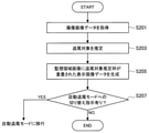
図5は、手動追尾モードでのカメラ110の駆動に係る演算処理方法の処理手順を示している。図5を参照すると、手動追尾モードでのカメラ110の駆動に係る演算処理方法では、まず、オペレータの操作に応じたPTZ制御値に従って、カメラ110が駆動される(ステップS101)。つまり、手動での追尾対象の追尾が行われる。ステップS101に示す処理は、図1に示す駆動制御部117が、PTZ操作入力装置140を介して入力されるオペレータの指示に応じたPTZ制御値に従って、駆動機構112を駆動させる処理に対応している。
(3-1. Manual tracking mode)
(3-1-1. Arithmetic processing method related to camera drive)
FIG. 5 shows a processing procedure of an arithmetic processing method related to driving the
次に、追尾モードを自動追尾モードに切り替える旨の指示が入力されたかどうかが判断される(ステップS103)。ステップS103に示す処理は、図1に示す追尾モード設定部115によって実行される処理に対応している。当該指示の入力がなかった場合には、追尾モードは切り替えられないため、一連の処理を終了し、次にオペレータから入力される指示に応じてステップS101以降の処理が繰り返し実行される。
Next, it is determined whether or not an instruction to switch the tracking mode to the automatic tracking mode has been input (step S103). The process shown in step S103 corresponds to the process executed by the tracking
一方、ステップS103で追尾モードを自動追尾モードに切り替える旨の指示の入力があった場合には、当該指示に従って追尾モード設定部115によって追尾モードが切り替えられ、自動追尾モードに移行する。自動追尾モードでは、後述する図7及び図8に示す処理が実行される。
On the other hand, when an instruction to switch the tracking mode to the automatic tracking mode is input in step S103, the tracking
(3−1−2.表示画像データの生成に係る演算処理方法)
図6は、手動追尾モードでの表示画像データの生成に係る演算処理方法の処理手順を示している。なお、図6に示す一連の処理を実行している間には、図5に示す一連の処理(すなわち、手動での追尾処理)が随時行われている。また、図6に示す一連の処理は、カメラ110によって撮影される1フレーム分の撮像画像データに対応する処理に対応している。
(3-1-2. Operation processing method related to generation of display image data)
FIG. 6 shows a processing procedure of an arithmetic processing method related to generation of display image data in the manual tracking mode. While the series of processes shown in FIG. 6 is being executed, the series of processes shown in FIG. 5 (that is, manual tracking processing) is being performed at any time. Further, the series of processes shown in FIG. 6 correspond to the processes corresponding to the captured image data for one frame captured by the
図6を参照すると、手動追尾モードでの表示画像データの生成に係る演算処理方法では、まず、手動での追尾中に撮像画像データが取得される(ステップS201)。ステップS201に示す処理は、図1に示す撮像部111によって手動での追尾中に随時生成され、メモリ113に格納された撮像画像データを、追尾対象推定部118及び表示画像データ生成部119が取得する処理に対応している。
Referring to FIG. 6, in the arithmetic processing method relating to the generation of the display image data in the manual tracking mode, first, the captured image data is acquired during the manual tracking (step S201). The process shown in step S201 is generated at any time by the
次に、手動での追尾中に取得された撮像画像データに基づいて、追尾対象が推定される(ステップS203)。ステップS203に示す処理は、図1に示す追尾対象推定部118によって実行される処理に対応している。
Next, the tracking target is estimated based on the captured image data acquired during the manual tracking (step S203). The process shown in step S203 corresponds to the process executed by the tracking
次に、監視領域画像に追尾対象推定枠が重畳された表示画像データが生成される(ステップS205)。ステップS205に示す処理は、図1に示す表示画像データ生成部119によって実行される処理に対応している。
Next, the display image data in which the tracking target estimation frame is superimposed on the monitoring area image is generated (step S205). The process shown in step S205 corresponds to the process executed by the display image
次に、追尾モードを自動追尾モードに切り替える旨の指示が入力されたかどうかが判断される(ステップS207)。ステップS207に示す処理は、図1に示す追尾モード設定部115によって実行される処理に対応している。ステップS207で当該指示の入力がなかった場合には、追尾モードは切り替えられないため、一連の処理を終了し、次フレームに対してステップS201以降の処理が繰り返し実行される。
Next, it is determined whether or not an instruction to switch the tracking mode to the automatic tracking mode has been input (step S207). The process shown in step S207 corresponds to the process executed by the tracking
一方、ステップS207で追尾モードを自動追尾モードに切り替える旨の指示の入力があった場合には、当該指示に従って追尾モード設定部115によって追尾モードが切り替えられ、自動追尾モードに移行する。自動追尾モードでは、後述する図7及び図8に示す処理が実行される。
On the other hand, when an instruction to switch the tracking mode to the automatic tracking mode is input in step S207, the tracking
(3−2.自動追尾モード)
(3−2−1.カメラの駆動に係る演算処理方法)
図7は、自動追尾モードでのカメラ110の駆動に係る演算処理方法の処理手順を示している。図7を参照すると、自動追尾モードでのカメラ110の駆動に係る演算処理方法では、まず、撮像画像データに基づいて、追尾対象を自動追尾するためのPTZ制御値が算出される(ステップS301)。ステップS301に示す処理は、図1に示す自動追尾PTZ制御値算出部116によって実行される処理に対応している。
(3-2. Automatic tracking mode)
(3-2-1. Arithmetic processing method related to camera drive)
FIG. 7 shows a processing procedure of an arithmetic processing method related to driving the
次に、算出されたPTZ制御値に従って、カメラ110が駆動される(ステップS303)。つまり、自動での追尾対象の追尾が行われる。ステップS303に示す処理は、図1に示す駆動制御部117が、自動追尾PTZ制御値算出部116によって算出されるPTZ制御値に従って、駆動機構112を駆動させる処理に対応している。
Next, the
次に、追尾モードを手動追尾モードに切り替える旨の指示が入力されたかどうかが判断される(ステップS305)。ステップS305に示す処理は、図1に示す追尾モード設定部115によって実行される処理に対応している。当該指示の入力がなかった場合には、追尾モードは切り替えられないため、一連の処理を終了し、次にPTZ制御値が算出されるタイミングでステップS301以降の処理が繰り返し実行される。なお、PTZ制御値が算出される間隔は、撮像画像データが生成されるフレームレートと同様であってもよいし、当該フレームレートよりも遅い任意の間隔であってもよい。
Next, it is determined whether or not an instruction to switch the tracking mode to the manual tracking mode has been input (step S305). The process shown in step S305 corresponds to the process executed by the tracking
一方、ステップS305で追尾モードを手動追尾モードに切り替える旨の指示の入力があった場合には、当該指示に従って追尾モード設定部115によって追尾モードが切り替えられ、手動追尾モードに移行する。手動追尾モードでは、上述した図5及び図6に示す処理が実行される。
On the other hand, when an instruction to switch the tracking mode to the manual tracking mode is input in step S305, the tracking
(3−2−2.表示画像データの生成に係る演算処理方法)
図8は、自動追尾モードでの表示画像データの生成に係る演算処理方法の処理手順を示している。なお、図8に示す一連の処理を実行している間には、図7に示す一連の処理(すなわち、自動での追尾処理)が随時行われている。また、図8に示す一連の処理は、カメラ110によって撮影される1フレーム分の撮像画像データに対応する処理に対応している。
(3-2-2. Arithmetic processing method related to the generation of display image data)
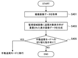
FIG. 8 shows a processing procedure of an arithmetic processing method related to generation of display image data in the automatic tracking mode. While the series of processes shown in FIG. 8 is being executed, the series of processes shown in FIG. 7 (that is, automatic tracking processing) is being performed at any time. Further, the series of processes shown in FIG. 8 correspond to the processes corresponding to the captured image data for one frame captured by the
図8を参照すると、自動追尾モードでの表示画像データの生成に係る演算処理方法では、まず、自動での追尾中に撮像画像データが取得される(ステップS401)。ステップS401に示す処理は、図1に示す撮像部111によって自動での追尾中に随時生成され、メモリ113に格納された撮像画像データを、表示画像データ生成部119が取得するに対応している。
Referring to FIG. 8, in the arithmetic processing method related to the generation of the display image data in the automatic tracking mode, first, the captured image data is acquired during the automatic tracking (step S401). The process shown in step S401 is generated at any time during automatic tracking by the
次に、自動での追尾中に取得された撮像画像データに基づいて、監視領域画像に追尾対象表示枠が重畳された表示画像データが生成される(ステップS403)。ステップS403に示す処理は、図1に示す表示画像データ生成部119によって実行される処理に対応している。
Next, based on the captured image data acquired during automatic tracking, display image data in which the tracking target display frame is superimposed on the monitoring area image is generated (step S403). The process shown in step S403 corresponds to the process executed by the display image
次に、追尾モードを手動追尾モードに切り替える旨の指示が入力されたかどうかが判断される(ステップS405)。ステップS405に示す処理は、図1に示す追尾モード設定部115によって実行される処理に対応している。ステップS405で当該指示の入力がなかった場合には、追尾モードは切り替えられないため、一連の処理を終了し、次フレームに対してステップS401以降の処理が繰り返し実行される。
Next, it is determined whether or not an instruction to switch the tracking mode to the manual tracking mode has been input (step S405). The process shown in step S405 corresponds to the process executed by the tracking
一方、ステップS407で追尾モードを手動追尾モードに切り替える旨の指示の入力があった場合には、当該指示に従って追尾モード設定部115によって追尾モードが切り替えられ、手動追尾モードに移行する。手動追尾モードでは、上述した図5及び図6に示す処理が実行される。
On the other hand, when an instruction to switch the tracking mode to the manual tracking mode is input in step S407, the tracking
以上、本実施形態に係る演算処理方法の処理手順について説明した。 The processing procedure of the arithmetic processing method according to the present embodiment has been described above.
(4.追尾対象の推定処理)
図1に示す追尾対象推定部118が行う追尾対象の推定処理の詳細について説明する。本実施形態では、追尾対象推定部118は、以下のいずれかの方法に従って、手動での追尾中に追尾対象を推定することができる。
(4. Estimating processing of tracking target)
The details of the tracking target estimation process performed by the tracking
(4−1.色による追尾対象の推定処理)
追尾対象推定部118は、監視領域画像において、前景領域の中で周囲と色が異なる領域を追尾対象が存在する領域と推定することができる。図9は、このような、追尾対象の推定処理の一例である、色を用いた追尾対象の推定処理の処理手順を示すフロー図である。なお、図9に示す追尾対象の推定処理では、手動での追尾中には、追尾対象は画角内の略中央に存在し続けていること、及び追尾対象は周囲の背景とは異なる色を有すること、の2点を前提として、追尾対象が推定される。
(4-1. Estimating processing of tracking target by color)
The tracking
図9を参照すると、色を用いた追尾対象の推定処理では、まず、撮像画像データが取得され、バッファしている所定のフレーム分の撮像画像データ(フレームバッファ)が最新のものに更新される(ステップS501)。ステップS501に示す処理は、図1に示す撮像部111によって手動での追尾中に随時生成され、メモリ113に格納された撮像画像データを、追尾対象推定部118が取得し、フレームバッファを更新する処理に対応している。
Referring to FIG. 9, in the estimation process of the tracking target using color, first, the captured image data is acquired, and the captured image data (frame buffer) for a predetermined frame buffered is updated to the latest one. (Step S501). The process shown in step S501 is generated at any time by the
次に、前景領域及び後景領域の色ヒストグラムが算出される(ステップS503)。具体的な色ヒストグラムの算出処理としては、各種の公知の方法が用いられてよい。ここで、前景領域は、画角の中心から所定の範囲の領域として予め設定されている。また、後景領域は、当該前景領域の周囲の所定の範囲の領域として予め設定されている。この前景領域及び後景領域の設定は、上述した追尾対象は画角内の略中央に存在し続けているとの前提に基づくものである。 Next, the color histograms of the foreground region and the background region are calculated (step S503). As a specific color histogram calculation process, various known methods may be used. Here, the foreground region is preset as an region within a predetermined range from the center of the angle of view. Further, the background area is preset as an area of a predetermined range around the foreground area. The setting of the foreground region and the background region is based on the premise that the above-mentioned tracking target continues to exist in the substantially center of the angle of view.
次に、算出された色ヒストグラムに基づいて、前景領域の中から、前景領域の方により多く存在する色を含む領域が抽出される(ステップS505)。そして、抽出された領域の最外矩形が、追尾対象推定枠として画定される(ステップS507)。これらの処理は、上述した追尾対象は周囲の背景とは異なる色を有するとの前提に基づくものである。 Next, based on the calculated color histogram, a region containing more colors in the foreground region is extracted from the foreground region (step S505). Then, the outermost rectangle of the extracted region is defined as a tracking target estimation frame (step S507). These processes are based on the premise that the tracked object described above has a color different from that of the surrounding background.
(4−2.移動体の検出による追尾対象の推定処理)
追尾対象推定部118は、監視領域画像内で検出された移動体を前記追尾対象と推定することができる。図10は、このような、追尾対象の推定処理の一例である、移動体の検出による追尾対象の推定処理の処理手順を示すフロー図である。なお、図10に示す追尾対象の推定処理では、手動での追尾中には追尾対象は画角内の略中央に存在し続けていることを前提として、追尾対象が推定される。
(4-2. Estimating processing of tracking target by detecting moving object)
The tracking
図10を参照すると、移動体の検出による追尾対象の推定処理では、まず、撮像画像データが取得され、バッファしている所定のフレーム分の撮像画像データ(フレームバッファ)が最新のものに更新される(ステップS601)。ステップS601に示す処理は、図1に示す撮像部111によって手動での追尾中に随時生成され、メモリ113に格納された撮像画像データを、追尾対象推定部118が取得し、フレームバッファを更新する処理に対応している。
Referring to FIG. 10, in the estimation process of the tracking target by detecting a moving object, first, the captured image data is acquired, and the captured image data (frame buffer) for a predetermined frame buffered is updated to the latest one. (Step S601). The process shown in step S601 is generated at any time by the
次に、バッファしたフレーム間で監視領域画像の位置合わせが行われる(ステップS603)。 Next, the monitoring area image is aligned between the buffered frames (step S603).
次に、位置合わせされた監視領域画像について、フレーム間での差分が算出される(ステップS605)。 Next, the difference between the frames is calculated for the aligned monitoring area image (step S605).
次に、算出されたフレーム間差分に基づいて、移動体に対応する領域が抽出される(ステップS607)。 Next, a region corresponding to the moving body is extracted based on the calculated difference between frames (step S607).
そして、抽出された領域の中で、画角の中央付近に存在する領域の最外矩形が、追尾対象推定枠として画定される(ステップS609)。当該処理は、上述した追尾対象は画角内の略中央に存在し続けているとの前提に基づくものである。 Then, in the extracted region, the outermost rectangle of the region existing near the center of the angle of view is defined as the tracking target estimation frame (step S609). This process is based on the premise that the above-mentioned tracking target continues to exist in the substantially center of the angle of view.
(4−3.その他の追尾対象の推定処理)
その他、追尾対象推定部118は、以下に記載する方法によって追尾対象を推定してもよい。
(4-3. Estimating processing of other tracking targets)
In addition, the tracking
例えば、追尾対象推定部118は、以上説明した推定処理に対して、画像認識処理を組み合わせてもよい。例えば、事前に追尾対象の視覚的な特徴(例えば、人物であれば顔、服装、体型等)を設定しておく。追尾対象推定部118は、撮像画像データに対して画像認識処理を行うことにより、監視領域画像内から、設定された特徴に適合する人物又は物体を追尾対象の候補として抽出する。そして、その抽出した追尾対象の候補の中から、上述した方法に従って、色、又は移動体の検出結果に基づいて最終的な追尾対象を推定する。当該方法によれば、事前に設定された外観的な特徴を有する人物又は物体以外は追尾対象として推定されないこととなるため、追尾対象の推定処理の精度をより向上させることが可能になる。
For example, the tracking
あるいは、例えば、追尾対象推定部118は、オペレータの「くせ」も加味して、追尾対象を推定してもよい。例えば、オペレータをIDによって管理し、現在手動で追尾を行っているオペレータを監視システム1が個別に認識可能にする。また、手動での追尾中におけるオペレータごとの操作の傾向をデータベース化しておく。当該操作の傾向のデータベースには、例えば、オペレータごとの手動での追尾中における画角内での追尾対象の大きさ、位置等についての情報が含まれ得る。そして、追尾対象推定部118は、追尾対象の推定処理を実行する際に、IDによって現在手動で追尾を行っているオペレータを認識するとともに、上記データベースにアクセスすることにより、当該オペレータの操作の傾向を把握する。そして、その把握したオペレータの操作の傾向を加味して、上述した色を用いた追尾対象の推定処理又は移動体の検出による追尾対象の推定処理を実行する。
Alternatively, for example, the tracking
例えば、以上説明した色を用いた追尾対象の推定処理又は移動体の検出による追尾対象の推定処理では、画角の略中央に追尾対象が存在するとの前提の下に推定処理が行われていたが、現在手動で追尾を行っているオペレータが、画角の中央から比較的左に寄った位置において、画角の略1/4程度の大きさで追尾対象を捉える傾向が強いことが、データベースを介して把握されている場合には、追尾対象推定部118は、追尾対象が画角の中央から比較的左に寄った位置において上記の大きさを有するとの前提の下で、色、又は移動体の検出結果に基づいて追尾対象を推定する。当該方法によれば、オペレータごとの操作の「くせ」を考慮して追尾対象を推定することができるため、追尾対象の推定処理の精度をより向上させることが可能になる。
For example, in the estimation process of the tracking target using the colors described above or the estimation process of the tracking target by detecting the moving object, the estimation process is performed on the premise that the tracking target exists in the substantially center of the angle of view. However, there is a strong tendency for operators who are currently manually tracking to capture the tracking target at a position relatively to the left of the center of the angle of view, with a size of about 1/4 of the angle of view. When grasped through the above, the tracking
あるいは、上述した色を用いた追尾対象の推定処理及び移動体の検出による追尾対象の推定処理以外の方法として、追尾対象推定部118は、表示画像データにおける画像の見掛けの移動速度(すなわち、表示装置120に表示される画像の見掛けの移動速度)と、監視領域画像内での人物又は物体の移動速度との関係に基づいて、追尾対象を推定してもよい。具体的には、手動で追尾を行っている最中には、表示装置120に表示される画像内の略一定の位置に追尾対象が表示されるように、パン、チルト及び/又はズームが操作される場合が多いため、表示画像データにおける画像の見掛けの移動速度と、追尾対象となる移動体の移動速度とは略等しいと考えられる。従って、追尾対象推定部118は、表示画像データにおける画像の見掛けの移動速度と略等しく移動している人物又は物体(すなわち、表示装置120に表示される画像内において略一定の場所に存在し続ける人物又は物体)を、監視領域画像の中から抽出し、その抽出した人物又は物体を追尾対象として推定してもよい。
Alternatively, as a method other than the above-mentioned estimation process of the tracking object using the color and the estimation process of the tracking object by detecting the moving object, the tracking
ここで、上記のいずれかの推定方法の結果、例えば画角の中央付近に移動体が複数存在する場合等、監視領域画像内において追尾対象の候補が複数推定される場合もあり得る。この場合、追尾対象推定部118は、適当な評価関数によってそれらの追尾対象の候補の確からしさを評価し、それらの中から最も適切なものを1つだけ選定して、最終的な追尾対象として推定する。例えば、追尾対象推定部118は、複数抽出された追尾対象の候補の中で、最も画角の中央に存在するものを最終的な追尾対象として推定する。このように、追尾対象推定部118が最終的な追尾対象を1つだけ選定することにより、オペレータに対して表示される追尾対象推定枠も1つだけになる。従って、上述したような、ワンアクションでの追尾対象の指定が可能となり、オペレータの操作性の向上が実現され得る。もしも追尾対象推定部118による推定が誤っており、オペレータの所望の人物又は物体に追尾対象推定枠が表示されなかった場合には、上述したように、追尾対象推定枠が適切に表示されるまで、追尾モードを切り替えずに手動での追尾を続行すればよい。
Here, as a result of any of the above estimation methods, there may be a case where a plurality of tracking target candidates are estimated in the monitored area image, for example, when a plurality of moving objects are present near the center of the angle of view. In this case, the tracking
ただし、本実施形態はかかる例に限定されず、追尾対象推定部118が追尾対象の候補を複数推定した場合には、表示画像データ生成部119は、それらに対応して、複数の追尾対象推定枠を監視領域画像に重畳させてもよい。この場合、監視システム1では、オペレータに対して、これら複数の追尾対象推定枠の中から1つを選択し、自動追尾モードにおける追尾対象を指定するGUIが提供され得る。当該GUIによれば、複数の追尾対象推定枠の中から1つを選択する操作が要求される分、上記のワンアクションでの操作に比べて追尾対象の指定に係るオペレータの操作の手間は増大するが、上述したような追尾対象推定枠が適切に表示されるまで手動での追尾を続行する作業を行う必要はなくなるため、手動追尾モードでの追尾を実行する時間を短くできる可能性があり、相対的にはオペレータの作業負荷を軽減できる可能性がある。追尾対象推定枠を1つだけ表示させるか、複数表示させるかは、オペレータの特性(例えば性格や嗜好、技量等)、及び監視対象領域の環境等に応じて、適宜設定されてよい。
However, this embodiment is not limited to such an example, and when the tracking
また、以上説明した各方法は、併用されてもよい。例えば、追尾対象推定部118は、以上説明した方法をそれぞれ並行して実行し、各方法によってそれぞれ追尾対象を推定してもよい。この場合、各方法に応じて複数の追尾対象が推定され得るが、上記のように、追尾対象推定部118は、適当な評価関数を用いてその推定された複数の追尾対象の中から最も確からしい1つのみを選定してもよいし、推定された複数の追尾対象の全てに追尾対象推定枠が表示されてもよい。
Moreover, each method described above may be used together. For example, the tracking
(5.変形例)
以上説明した実施形態におけるいくつかの変形例について説明する。
(5. Modification example)
Some modifications of the embodiments described above will be described.
(5−1.装置構成が異なる変形例)
図11を参照して、本実施形態の一変形例である、監視システムが異なる装置構成を有する変形例について説明する。図11は、装置構成が異なる変形例に係る監視システムの概略構成を示すブロック図である。
(5-1. Modification example with different device configuration)
With reference to FIG. 11, a modified example in which the monitoring system has a different device configuration, which is a modified example of the present embodiment, will be described. FIG. 11 is a block diagram showing a schematic configuration of a monitoring system according to a modified example having a different device configuration.
図11を参照すると、本変形例に係る監視システム2は、カメラ210と、表示装置120と、追尾モード切り替え入力装置130と、PTZ操作入力装置140と、メモリ113と、演算処理装置250と、を備える。ここで、表示装置120、追尾モード切り替え入力装置130、PTZ操作入力装置140及びメモリ113は、図1に示すものと同様の構成及び機能を有するものである。
Referring to FIG. 11, the
カメラ210はPTZカメラであり、オペレータによる手動での操作に応じて、又は自動で、PTZ制御が可能である。カメラ210は、撮像部111と、駆動機構112と、を有する。撮像部111及び駆動機構112は、図1に示すものと同様の構成及び機能を有するものである。
The
演算処理装置250は、例えばCPUやDSP等のプロセッサによって構成され、所定の処理を実行することにより、監視システム2の動作を統合的に制御する。演算処理装置250は、その機能として、追尾モード設定部115と、自動追尾PTZ制御値算出部116と、駆動制御部117と、追尾対象推定部118と、表示画像データ生成部119と、を有する。演算処理装置250を構成するプロセッサが所定のプログラムに従って演算処理を実行することにより、上記の各機能が実現される。なお、演算処理装置250は、図1に示す演算処理装置114と同様の構成及び機能を有するものである。
The
監視システム2では、これらの装置のうち、カメラ210は、監視領域を撮影し得る場所に設置され、表示装置120、追尾モード切り替え入力装置130、PTZ操作入力装置140、メモリ113及び演算処理装置250は、オペレータが監視業務を行う場所に設置される。つまり、カメラ210と、その他の装置とは、互いに離れた場所に設置され、ネットワークを介して互いに通信可能に接続されている。
In the
このように、上述した実施形態に係る監視システム1では、カメラ110にメモリ113及び演算処理装置114が搭載されていたのに対して、本変形例に係る監視システム2では、メモリ113及び演算処理装置114はオペレータ側に設置される。本実施形態では、本変形例のように、メモリ113及び演算処理装置114がオペレータ側に設置されて、当該監視システム2が構成されてもよい。なお、監視システム2において、メモリ113及び演算処理装置114の設置場所以外の事項は、監視システム1と同様であるため、各装置についての詳細な説明は省略する。
As described above, in the monitoring system 1 according to the above-described embodiment, the
(5−2.電子的なPTZカメラを備える変形例)
図12を参照して、本実施形態の他の変形例である、監視システムが電子的なPTZカメラを備える変形例について説明する。図12は、電子的なPTZカメラを備える変形例に係る監視システムの概略構成を示すブロック図である。
(5-2. Modification example equipped with an electronic PTZ camera)
A modified example in which the monitoring system includes an electronic PTZ camera, which is another modified example of the present embodiment, will be described with reference to FIG. 12. FIG. 12 is a block diagram showing a schematic configuration of a monitoring system according to a modified example including an electronic PTZ camera.
図12を参照すると、本変形例に係る監視システム3は、カメラ310と、表示装置120と、追尾モード切り替え入力装置130と、PTZ操作入力装置140と、を備える。ここで、表示装置120、追尾モード切り替え入力装置130及びPTZ操作入力装置140は、図1に示すものと同様の構成及び機能を有するものである。
Referring to FIG. 12, the monitoring system 3 according to this modification includes a camera 310, a
カメラ310はPTZカメラであり、オペレータによる手動での操作に応じて、又は自動で、PTZ制御が可能である。カメラ310は、撮像部111と、メモリ113と、演算処理装置314と、を有する。撮像部111及びメモリ113は、図1に示すものと同様の構成及び機能を有するものである。
The camera 310 is a PTZ camera, and PTZ control can be performed according to a manual operation by an operator or automatically. The camera 310 includes an
ここで、本変形例に係るカメラ310では、PTZ制御を行う際に、駆動機構によってハードウェア(上述した実施形態であればズームレンズや雲台等)を動作させるのではなく、取得された撮像画像データに対して画像処理を施すことによってパン、チルト及び/又はズームの変更を実現する。このようなソフトウェア的にPTZ制御を実行可能なPTZカメラのことを、本明細書では電子的なPTZカメラともいうこととする。 Here, in the camera 310 according to the present modification, when the PTZ control is performed, the hardware (zoom lens, pan head, etc. in the above-described embodiment) is not operated by the drive mechanism, but the acquired image is captured. Pan, tilt and / or zoom can be changed by performing image processing on the image data. Such a PTZ camera capable of performing PTZ control by software is also referred to as an electronic PTZ camera in the present specification.
具体的には、本変形例では、カメラ310の撮像部111は、比較的高解像度で、広角な画像を撮影可能なように構成される。そして、撮像部111が生成した撮像画像データの画角内の一部を切り出して適宜拡大することにより、パン、チルト及び/又はズームが変更された表示画像データが生成される。例えば、右方向にパンを変更する場合であれば、そのパンに係る制御値に対応するだけ画角の中央から右側にずれた部位を切り出し、表示画面に合うように適宜拡大して表示画像データが生成される。撮像部111が比較的高解像度の画像を撮影可能に構成されることにより、このような切り出し処理を行っても、表示画像データの画質が著しく劣化することはない。
Specifically, in this modification, the
このように、カメラ310が電子的なPTZカメラとして構成されることにより、カメラ310には、上述した実施形態とは異なり、駆動機構は設けられない。そして、これに対応して、演算処理装置314の機能も上述した実施形態とは異なる。 As described above, since the camera 310 is configured as an electronic PTZ camera, the camera 310 is not provided with a drive mechanism unlike the above-described embodiment. Correspondingly, the function of the arithmetic processing unit 314 is also different from the above-described embodiment.
演算処理装置314の機能について詳細に説明する。演算処理装置314は、例えばCPUやDSP等のプロセッサによって構成され、所定の処理を実行することにより、監視システム3の動作を統合的に制御する。演算処理装置314は、その機能として、追尾モード設定部315と、自動追尾PTZ制御値算出部316と、追尾対象推定部318と、表示画像データ生成部319と、を有する。演算処理装置314を構成するプロセッサが所定のプログラムに従って演算処理を実行することにより、上記の各機能が実現される。 The function of the arithmetic processing unit 314 will be described in detail. The arithmetic processing device 314 is configured by a processor such as a CPU or a DSP, and controls the operation of the monitoring system 3 in an integrated manner by executing a predetermined process. The arithmetic processing unit 314 has a tracking mode setting unit 315, an automatic tracking PTZ control value calculation unit 316, a tracking target estimation unit 318, and a display image data generation unit 319 as its functions. Each of the above functions is realized by the processor constituting the arithmetic processing unit 314 executing arithmetic processing according to a predetermined program.
追尾モード設定部315の機能は、図1に示す追尾モード設定部115と同様である。ただし、本変形例では、上述した実施形態とは異なり駆動制御部117は設けられないため、追尾モード設定部315は、設定した現在の追尾モードについての情報を、自動追尾PTZ制御値算出部316、及び追尾対象推定部318及び表示画像データ生成部319に提供する。
The function of the tracking mode setting unit 315 is the same as that of the tracking
自動追尾PTZ制御値算出部316は、図1に示す自動追尾PTZ制御値算出部116に対応するものである。自動追尾PTZ制御値算出部316は、自動追尾モードにおいて、追尾対象を追尾するためのPTZ制御値を算出する。PTZ制御値の算出方法は、上述した実施形態と同様である。ここで、上述した実施形態では、自動追尾PTZ制御値算出部116は、算出したPTZ制御値についての情報を駆動制御部117に提供していたが、本変形例では、PTZ制御に係るカメラ310の駆動制御は行われず、上記のように画像処理によってPTZ制御が行われる。従って、本変形例では、自動追尾PTZ制御値算出部316は、算出したPTZ制御値についての情報を、表示画像データ生成部319に提供する。
The automatic tracking PTZ control value calculation unit 316 corresponds to the automatic tracking PTZ control
追尾対象推定部318は、図1に示す追尾対象推定部118に対応するものである。追尾対象推定部318は、手動追尾モードにおいてオペレータの操作に従って追尾対象が追尾されている最中に、その追尾対象を推定する。追尾対象の推定処理の具体的な方法は、上述した実施形態と同様である。ここで、上述した実施形態では、追尾対象推定部118は、メモリ113に格納されている撮像画像データに基づいて追尾対象を推定していたが、本変形例では、上記のように画像処理によってPTZ制御が行われるため、手動で追尾している間において、撮像画像データはほぼ変化せず(すなわち、一定の画角の画像が撮影され続け)、表示画像データにおいて追尾対象が追尾されている画像が得られることとなる。従って、本変形例では、追尾対象推定部318は、手動での追尾中に表示画像データ生成部319によって生成された表示画像データに基づいて、追尾対象を推定する。追尾対象推定部318は、推定した追尾対象についての情報を、表示画像データ生成部319に提供する。
The tracking target estimation unit 318 corresponds to the tracking
表示画像データ生成部319は、図1に示す表示画像データ生成部119に対応するものである。表示画像データ生成部319は、表示装置120に表示させる画像データを生成する。具体的には、表示画像データ生成部319は、自動追尾モードにおいては、メモリ113に格納されている撮像画像データと、自動追尾PTZ制御値算出部316によって算出されたPTZ制御値についての情報と、に基づいて、当該PTZ制御値に従って監視領域画像内の所定の領域を切り出して拡大するとともに、その拡大した領域に対して追尾対象表示枠が重畳された画像データとして、表示画像データを生成する。
The display image data generation unit 319 corresponds to the display image
また、手動追尾モードにおいては、表示画像データ生成部319に、PTZ操作入力装置140を介したオペレータのPTZ制御に係る指示が入力される。そして、表示画像データ生成部319は、手動追尾モードにおいて、メモリ113に格納されている撮像画像データと、追尾対象推定部118によって推定された追尾対象についての情報と、PTZ操作入力装置140を介して入力されるオペレータのPTZ制御に係る指示と、に基づいて、当該PTZ制御に係る指示に応じたPTZ制御値に従って監視領域画像内の所定の領域を切り出して拡大するとともに、その拡大した領域に追尾対象推定枠が重畳された画像データとして、表示画像データを生成する。
Further, in the manual tracking mode, an instruction related to the operator's PTZ control via the PTZ
以上説明したように、本実施形態では、電子的なPTZカメラを備える監視システム3が構成されてもよい。なお、図12に示す構成例では、演算処理装置314がカメラ310内に設けられていたが、上記(5−1.装置構成が異なる変形例)で説明した変形例と同様に、監視システム3も、演算処理装置314がカメラ310とは別個の装置としてオペレータ側に設けられて構成されてもよい。 As described above, in the present embodiment, the monitoring system 3 including an electronic PTZ camera may be configured. In the configuration example shown in FIG. 12, the arithmetic processing unit 314 is provided in the camera 310, but the monitoring system 3 is similar to the modification described in the above (5-1. Modification example in which the device configuration is different). Also, the arithmetic processing unit 314 may be provided on the operator side as a device separate from the camera 310.
(5−3.ドローンを備える変形例)
本実施形態の他の変形例である、監視システムがドローンを備える変形例について説明する。近年、ドローンにおいては、当該ドローンに搭載される撮像部を用いた追尾対象の自動追尾機能が搭載されつつある。しかしながら、ドローンにおいて、追尾モードを手動追尾モードから自動追尾モードに切り替える際には、操縦者(すなわち、オペレータ)は、追尾対象を指定する操作、及び追尾モードを切り替える操作を、ドローンを操縦しながら行う必要がある。従って、これらの操作を簡易に行えない場合には、オペレータには煩雑な作業が要求されることとなり、操縦ミスを誘発する恐れがある。
(5-3. Modification example with drone)
A modified example in which the monitoring system includes a drone, which is another modified example of the present embodiment, will be described. In recent years, drones are being equipped with an automatic tracking function for tracking targets using an imaging unit mounted on the drone. However, in the drone, when switching the tracking mode from the manual tracking mode to the automatic tracking mode, the operator (that is, the operator) performs an operation of designating the tracking target and an operation of switching the tracking mode while operating the drone. There is a need to do. Therefore, if these operations cannot be performed easily, the operator is required to perform complicated work, which may induce a steering error.
一方、以上説明したように、本実施形態に係る技術によれば、手動追尾モードから自動追尾モードに切り替える際に、追尾対象を指定する操作、及び追尾モードを切り替える操作を、ワンアクションで簡便に実行することが可能である。従って、本実施形態に係る技術を、ドローンを備える監視システムに適用することにより、オペレータの操作性を大幅に向上させることができる。 On the other hand, as described above, according to the technique according to the present embodiment, when switching from the manual tracking mode to the automatic tracking mode, the operation of specifying the tracking target and the operation of switching the tracking mode can be easily performed with one action. It is possible to do it. Therefore, by applying the technique according to the present embodiment to a monitoring system including a drone, the operability of the operator can be significantly improved.
(5−3−1.監視システムの構成)
図13を参照して、本実施形態の他の変形例である、監視システムがドローンを備える変形例について説明する。図13は、ドローンを備える変形例に係る監視システムの概略構成を示すブロック図である。
(5-3-1. Configuration of monitoring system)
A modified example in which the monitoring system includes a drone, which is another modified example of the present embodiment, will be described with reference to FIG. FIG. 13 is a block diagram showing a schematic configuration of a monitoring system according to a modified example including a drone.
図13を参照すると、本変形例に係る監視システム4は、ドローン510と、表示装置120と、送信機530と、を備える。ここで、表示装置120は、図1に示すものと同様の構成及び機能を有するものである。なお、図示する構成例では、表示装置120と送信機530は別個の装置として配置されているが、表示装置120は、送信機530と一体的に構成されてもよい。
Referring to FIG. 13, the
送信機530は、ドローン510を操縦するための各種の指示を入力するための入力装置である。送信機530に入力された各種の指示は、無線通信によって、ドローン510に対して送信される。送信機530は、その機能として、追尾モード切り替え入力部531と、機体動作入力部532と、を有する。
The
追尾モード切り替え入力部531は、図1に示す追尾モード切り替え入力装置130と同様の機能を有するものである。オペレータは、追尾モード切り替え入力部531を介して、追尾モードを手動追尾モード又は自動追尾モードに切り替える旨の指示を、ドローン510に対して入力することができる。追尾モード切り替え入力部531は、例えばボタン等、ワンアクションでその切り替えの指示を入力可能な入力装置によって構成される。
The tracking mode switching
機体動作入力部532は、ドローン510を動作させる旨の指示を、当該ドローン510に入力する機能を有する。機体動作入力部532は、例えばジョイスティック等の入力装置によって構成される。ただし、機体動作入力部532の装置構成はかかる例に限定されず、機体動作入力部532は、一般的なドローンの送信機において当該ドローンの動作の指示入力に用いられている入力装置によって構成されてよい。オペレータは、機体動作入力部532を介して、ドローン510を移動(上昇、下降、前進、後退、及び旋回等)させる旨の指示を入力することができる。また、後述する撮像部111が、ドローン510の機体に対してジンバル構造等を介して移動可能に取り付けられている場合であれば、オペレータは、機体動作入力部532を介して、当該撮像部111を機体に対して移動させる旨の指示を入力してもよい。本明細書では、上述したドローン510を移動させる動作、及びジンバル構造等を介して撮像部111を移動させる動作を、「機体の動作」と総称することとする。
The aircraft
ここで、監視システム4では、ドローン510に搭載された撮像部111によって、追尾対象の追尾を行う。このとき、当該撮像部111のパン、チルト及び/又はズームの制御は、ドローン510の機体を動作させることによって、実現される。例えば、パンは、ドローン510の機体を、鉛直方向を回転軸方向として回転動作させる(ヨーイングさせる)ことで実現される。また、例えば、チルトは、ドローン510の機体を、左右方向を回転軸方向として回転動作させる(ピッチングさせる)ことで実現される。また、例えば、ズームは、ドローン510の機体を、前進動作又は後退動作させることで実現される。なお、撮像部111が、ドローン510の機体に対してジンバル構造等を介して移動可能に取り付けられている場合であれば、パン及びチルトについては、ドローン510の機体全体を移動させることに代えて、又はドローン510の機体全体を移動させることに加えて、当該ジンバル構造を介して撮像部111を移動させることによって、実現されてもよい。
Here, in the
従って、手動追尾モードにおいては、機体動作入力部532を介したオペレータの指示入力に従ってドローン510の機体が動作されることにより、撮像部111のパン、チルト及び/又はズームが制御され、追尾対象が追尾されることとなる。
Therefore, in the manual tracking mode, the pan, tilt and / or zoom of the
ドローン510は、撮像部111と、機体駆動機構512と、メモリ113と、演算処理装置514と、無線通信部520と、を有する。本変形例では、ドローン510に搭載された撮像部111によって、追尾対象の追尾が行われる。
The
撮像部111及びメモリ113は、図1に示すものと同様の構成及び機能を有するものである。なお、本変形例では、撮像部111は、ドローン510の機体に対して、固定的に、又はジンバル構造を介して移動可能に取り付けられる。
The
無線通信部520は、信号を送受信するアンテナ、及び送受信する信号を処理する処理回路等から構成される。無線通信部520は、送信機530から送信される、追尾モードの切り替えについての指示や、ドローン510の機体の動作についての指示を受信し、これらの指示を演算処理装置514に提供する。また、無線通信部520は、演算処理装置514によって生成された表示画像データを、表示装置120に送信する。このように、本変形例では、送信機530は、少なくとも無線送信が可能に構成され、表示装置120は、少なくとも無線受信が可能に構成される。
The
機体駆動機構512は、ドローン510の機体を動作させるための駆動機構である。機体駆動機構512は、例えば、ドローン510移動用のプロペラを回転させるためのモータであり得る。また、撮像部111が、ドローン510の機体に対してジンバル構造等を介して移動可能に取り付けられている場合であれば、機体駆動機構512は、当該ジンバル構造等を介して撮像部111を移動させるためのモータを含んでもよい。
The
演算処理装置514は、例えばCPUやDSP等のプロセッサによって構成され、所定の処理を実行することにより、監視システム4の動作を統合的に制御する。演算処理装置514は、その機能として、追尾モード設定部515と、自動追尾機体動作制御値算出部516と、機体駆動制御部517と、追尾対象推定部518と、表示画像データ生成部519と、を有する。演算処理装置514を構成するプロセッサが所定のプログラムに従って演算処理を実行することにより、上記の各機能が実現される。
The
追尾モード設定部515の機能は、図1に示す追尾モード設定部115と略同様である。追尾モード設定部515は、無線通信部520を介して提供された、追尾モードの切り替えについての指示に応じて、追尾モードを手動追尾モード又は自動追尾モードに設定する。追尾モード設定部515は、設定した現在の追尾モードについての情報を、自動追尾機体動作制御値算出部516、及び追尾対象推定部518及び表示画像データ生成部519に提供する。
The function of the tracking
自動追尾機体動作制御値算出部516は、図1に示す自動追尾PTZ制御値算出部116に対応するものである。ここで、監視システム4では、上述したように、ドローン510の機体を動作させることによって、撮像部111のパン、チルト及び/又はズームを制御し、追尾対象の追尾を行う。従って、監視システム4では、自動追尾機体動作制御値算出部516は、自動追尾モードにおいて、追尾対象を追尾するためのパン、チルト及び/又はズームに係る制御値として、ドローン510の機体の動作を制御するための制御値(以下、機体動作制御値ともいう)を算出する。つまり、本変形例に係る機体動作制御値は、上述した実施形態におけるPTZ制御値に対応するものである。例えば、自動追尾機体動作制御値算出部516は、メモリ113に格納されている撮像画像データを解析することにより、かかる機体動作制御値を算出する。なお、自動追尾を実現するような機体動作制御値の算出方法としては、一般的なドローンにおいて用いられている各種の公知の方法が適用されてよいため、ここではその詳細な処理内容についての説明を省略する。
The automatic tracking machine operation control
自動追尾機体動作制御値算出部516は、算出した機体動作制御値についての情報を、機体駆動制御部517に提供する。
The automatic tracking machine operation control
機体駆動制御部517は、図1に示す駆動制御部117に対応するものである。本変形例では、機体駆動制御部517は、機体駆動機構512の駆動を制御することによって撮像部111のパン、チルト及び/又はズームを制御し、追尾対象を追尾するようにドローン510の機体を動作させる。機体駆動制御部517は、手動追尾モードにおいては、機体動作入力部532を介して入力されるオペレータの指示に応じた機体動作制御値に従って、機体駆動機構512を駆動させる。一方、機体駆動制御部517は、自動追尾モードにおいては、自動追尾機体動作制御値算出部516によって算出された機体動作制御値に従って、機体駆動機構512を駆動させる。
The airframe
追尾対象推定部518の機能は、図1に示す追尾対象推定部118と同様である。追尾対象推定部518は、手動追尾モードにおいてオペレータの指示に従って追尾対象が追尾されている最中に、その追尾対象を推定する。追尾対象の推定処理の具体的な方法は、上述した実施形態と同様である。追尾対象推定部518は、推定した追尾対象についての情報を、表示画像データ生成部519に提供する。また、追尾対象推定部518は、追尾モード設定部515から提供される情報に基づいて、追尾モードが手動追尾モードから自動追尾モードに切り替えられたことを把握した場合には、そのタイミングで推定している追尾対象についての情報を、自動追尾機体動作制御値算出部516に提供する。自動追尾機体動作制御値算出部516は、この追尾モードが手動追尾モードから自動追尾モードに切り替えられた際に推定されていた追尾対象を、自動追尾モードにおける追尾対象とみなして、自動追尾のための機体動作制御値を算出する。
The function of the tracking
表示画像データ生成部519の機能は、図1に示す表示画像データ生成部119と同様ある。自動追尾モードにおいては、表示画像データ生成部519は、メモリ113に格納されている撮像画像データに基づいて、監視領域画像に追尾対象表示枠が重畳された画像データとして、表示画像データを生成する。ただし、上述した実施形態と同様に、本変形例においても、自動追尾モードにおける表示画像に、追尾対象表示枠は必ずしも表示されなくてもよい。一方、手動追尾モードにおいては、表示画像データ生成部519は、メモリ113に格納されている撮像画像データと、追尾対象推定部518によって推定された追尾対象についての情報と、に基づいて、監視領域画像に追尾対象推定枠が重畳された画像データとして、表示画像データを生成する。
The function of the display image
以上、ドローン510を備える変形例に係る監視システム4の構成について説明した。以上説明したように、本変形例によれば、ドローン510を用いて追尾対象を追尾する際に、オペレータは、手動追尾モードから自動追尾モードへの切り替えの指示を、追尾モード切り替え入力部531を介したワンアクションの操作で入力することができる。このとき、切り替えの指示を入力した際に追尾対象推定枠が付されている追尾対象が、自動追尾モードにおける追尾対象として指定されるため、オペレータは、当該追尾対象を指定する操作を別途行う必要はない。従って、オペレータは、ドローン510を操縦しながらでも、簡便な操作で、より容易に、手動追尾モードから自動追尾モードへの切り替えを実行することが可能になる。よって、操縦ミス等を招くことなく、追尾対象の追尾をより円滑に実行することができ、オペレータの利便性が向上する。
The configuration of the
ここで、以上説明した構成例では、撮像部111のパン、チルト及び/又はズームの制御がドローン510の機体を動作させることによって実現されていたが、ドローン510を備える監視システムの構成はかかる例に限定されない。例えば、ドローン510の機体の動作とは独立して、撮像部111がパン、チルト及び/又はズームを実行可能である場合には、ドローン510を備える監視システムとして、撮像部111がドローン510に搭載されること以外は、上記(5−2.電子的なPTZカメラを備える変形例)までで説明した監視システムと同様の監視システムが構成されてよい。あるいは、パン、チルト及び/又はズームのうちの一部がドローン510の機体の動作によって実現され、残りのものが撮像部111の動作によって実現されてもよい。この場合には、監視システムは、図1に示す駆動機構112、自動追尾PTZ制御値算出部116、及び駆動制御部117、並びに図13に示す機体駆動機構512、自動追尾機体動作制御値算出部516及び機体駆動制御部517を少なくとも含むシステムによって実現され得る。具体的には、当該監視システムにおいては、パン、チルト及び/又はズームのうち、ドローン510の機体の動作によって実現されるものは、図13に示す機体駆動機構512、自動追尾機体動作制御値算出部516、及び機体駆動制御部517の構成及び機能によって制御され得る。また、当該監視システムにおいては、パン、チルト及び/又はズームのうち、撮像部111の動作によって実現されるものは、図1に示す駆動機構112、自動追尾PTZ制御値算出部116、及び駆動制御部117の構成及び機能によって制御され得る。もちろん、当該監視システムには、図1及び図13に示す他の構成及び機能が更に備えられてもよい。
Here, in the configuration example described above, the pan, tilt, and / or zoom control of the
(5−3−2.演算処理方法)
図14及び図15を参照して、以上説明した監視システム4の演算処理装置514において実行される、演算処理方法の処理手順について説明する。図14及び図15は、ドローン510を備える変形例に係る演算処理方法の処理手順の一例を示すフロー図である。
(5-3-2. Arithmetic processing method)
With reference to FIGS. 14 and 15, a processing procedure of the arithmetic processing method executed in the
ここで、演算処理装置514における演算処理としては、主に、ドローン510の機体の動作に係る演算処理と、表示画像データの生成に係る演算処理が実行され得る。このうち、表示画像データの生成に係る演算処理については、その方法は、上述した実施形態と同様である(例えば、かかる演算処理は、図6及び図8に示す処理手順によって実行され得る)。従って、ここでは、演算処理装置514における演算処理方法として、ドローン510の機体の動作に係る演算処理方法について具体的に説明する。
Here, as the arithmetic processing in the
(5−3−2−1.手動追尾モードでのドローンの機体の動作に係る演算処理方法)
図14は、手動追尾モードでのドローン510の機体の動作に係る演算処理方法の処理手順を示している。図14を参照すると、手動追尾モードでのドローン510の機体の動作に係る演算処理方法では、まず、オペレータの操作に応じた機体動作制御値に従って、ドローン510の機体が動作される(ステップS701)。ステップS701では、オペレータの操作に応じてドローン510の機体が動作されることにより、手動での追尾対象の追尾が行われる。ステップS701に示す処理は、図13に示す機体駆動制御部517が、機体動作入力部532を介して入力されるオペレータの指示に応じた機体動作制御値に従って、機体駆動機構512を駆動させる処理に対応している。
(5--3-2-1. Arithmetic processing method related to the operation of the drone aircraft in the manual tracking mode)
FIG. 14 shows a processing procedure of an arithmetic processing method relating to the operation of the
次に、追尾モードを自動追尾モードに切り替える旨の指示が入力されたかどうかが判断される(ステップS703)。ステップS703に示す処理は、図13に示す追尾モード設定部515によって実行される処理に対応している。当該指示の入力がなかった場合には、追尾モードは切り替えられないため、一連の処理を終了し、次にオペレータから入力される指示に応じてステップS701以降の処理が繰り返し実行される。
Next, it is determined whether or not an instruction to switch the tracking mode to the automatic tracking mode has been input (step S703). The process shown in step S703 corresponds to the process executed by the tracking
一方、ステップS703で追尾モードを自動追尾モードに切り替える旨の指示の入力があった場合には、当該指示に従って追尾モード設定部515によって追尾モードが切り替えられ、自動追尾モードに移行する。自動追尾モードでは、後述する図15に示す処理、及び上述した図8に示す処理が実行される。
On the other hand, when an instruction to switch the tracking mode to the automatic tracking mode is input in step S703, the tracking
(5−3−2−2.自動追尾モードでのドローンの機体の動作に係る演算処理方法)
図15は、自動追尾モードでのドローン510の機体の動作に係る演算処理方法の処理手順を示している。図15を参照すると、自動追尾モードでのドローン510の機体の動作に係る演算処理方法では、まず、撮像画像データに基づいて、追尾対象を自動追尾するための機体動作制御値が算出される(ステップS801)。ステップS801に示す処理は、図13に示す自動追尾機体動作制御値算出部516によって実行される処理に対応している。
(5-3-2-2. Arithmetic processing method related to the operation of the drone aircraft in the automatic tracking mode)
FIG. 15 shows a processing procedure of an arithmetic processing method related to the operation of the
次に、算出された機体動作制御値に従って、ドローン510の機体が動作される(ステップS803)。ステップS803では、ステップS801で算出された機体動作制御値に応じてドローン510の機体が動作されることにより、自動での追尾対象の追尾が行われる。ステップS803に示す処理は、図13に示す機体駆動制御部517が、自動追尾機体動作制御値算出部516によって算出される機体動作制御値に従って、機体駆動機構512を動作させる処理に対応している。
Next, the aircraft of the
次に、追尾モードを手動追尾モードに切り替える旨の指示が入力されたかどうかが判断される(ステップS805)。ステップS805に示す処理は、図13に示す追尾モード設定部515によって実行される処理に対応している。当該指示の入力がなかった場合には、追尾モードは切り替えられないため、一連の処理を終了し、次に機体動作制御値が算出されるタイミングでステップS801以降の処理が繰り返し実行される。なお、機体動作制御値が算出される間隔は、撮像画像データが生成されるフレームレートと同様であってもよいし、当該フレームレートよりも遅い任意の間隔であってもよい。
Next, it is determined whether or not an instruction to switch the tracking mode to the manual tracking mode has been input (step S805). The process shown in step S805 corresponds to the process executed by the tracking
一方、ステップS805で追尾モードを手動追尾モードに切り替える旨の指示の入力があった場合には、当該指示に従って追尾モード設定部515によって追尾モードが切り替えられ、手動追尾モードに移行する。手動追尾モードでは、上述した図14及び図6に示す処理が実行される。
On the other hand, when an instruction to switch the tracking mode to the manual tracking mode is input in step S805, the tracking
(6.補足)
以上、添付図面を参照しながら本開示の好適な実施形態について詳細に説明したが、本開示の技術的範囲はかかる例に限定されない。本開示の技術分野における通常の知識を有する者であれば、特許請求の範囲に記載された技術的思想の範疇内において、各種の変更例または修正例に想到し得ることは明らかであり、これらについても、当然に本開示の技術的範囲に属するものと了解される。
(6. Supplement)
Although the preferred embodiments of the present disclosure have been described in detail with reference to the accompanying drawings, the technical scope of the present disclosure is not limited to such examples. It is clear that anyone with ordinary knowledge in the art of the present disclosure may come up with various modifications or amendments within the scope of the technical ideas set forth in the claims. Is, of course, understood to belong to the technical scope of the present disclosure.
例えば、上記実施形態及びその変形例では、監視システムにおける各種の処理を実行する演算処理装置がカメラ又はドローンと一体的に構成される場合、及びオペレータ側に設置される場合について説明したが、本開示に係る技術はかかる例に限定されない。例えば、本開示に係る技術では、演算処理装置は、カメラとも、オペレータ側に設置される各種の装置(表示装置、追尾モード切り替え入力装置、PTZ操作入力装置、及び送信機)とも異なる場所に設置され、これらの装置が通信可能に接続されることにより、監視システムが構成されてもよい。この場合、例えば、演算処理装置は、いわゆるクラウド上に設置されてよい。 For example, in the above-described embodiment and its modification, the case where the arithmetic processing unit that executes various processes in the monitoring system is integrally configured with the camera or the drone and the case where the arithmetic processing unit is installed on the operator side have been described. The disclosed technology is not limited to such examples. For example, in the technique according to the present disclosure, the arithmetic processing device is installed in a place different from the camera and various devices (display device, tracking mode switching input device, PTZ operation input device, and transmitter) installed on the operator side. The monitoring system may be configured by connecting these devices so as to be communicable. In this case, for example, the arithmetic processing unit may be installed on a so-called cloud.
また、演算処理装置の具体的な装置構成は任意であってよい。例えば、演算処理装置は1台の装置であってもよいし、複数の装置によって構成されてもよい。演算処理装置が複数の装置によって構成される場合には、演算処理装置が有する各機能がこれら複数の装置に分散して搭載され、これら複数の装置が互いに各種の情報をやり取りすることにより、全体として上述した演算処理装置と同様の機能が実現され得る。 Further, the specific device configuration of the arithmetic processing unit may be arbitrary. For example, the arithmetic processing unit may be one device or may be composed of a plurality of devices. When the arithmetic processing unit is composed of a plurality of devices, each function of the arithmetic processing unit is distributed and mounted on the plurality of devices, and the plurality of devices exchange various information with each other to exchange various information with each other. The same function as the above-mentioned arithmetic processing unit can be realized.
また、上記実施形態及びその変形例では、撮像画像データがカメラ又はドローンに設けられた記憶装置(メモリ)に記録されていたが、本開示に係る技術はかかる例に限定されない。撮像画像データは、当該メモリに記録されるとともに、又は当該メモリに記録される代わりに、カメラ又はドローンとネットワークを介して接続される外部の記憶装置に記録されてもよい。 Further, in the above-described embodiment and its modification, the captured image data is recorded in a storage device (memory) provided in the camera or the drone, but the technique according to the present disclosure is not limited to such an example. The captured image data may be recorded in the memory, or instead of being recorded in the memory, may be recorded in an external storage device connected to the camera or drone via a network.
また、以上の実施形態では、監視を目的として追尾対象を追尾する監視システムが構成されていたが、本開示はかかる例に限定されない。本開示に係る技術は、他の用途に対しても適用可能である。具体的には、本開示に係る技術は、監視目的だけでなく、より広く、撮影対象である人物、動物又は物体を追尾しながら撮影し、その撮影された撮影対象領域の画像(撮影領域画像)をオペレータに対して提示する、撮影システムに対して適用され得るものである。例えば、監視以外の撮影の目的として、人物等の観察や、人物等の活動を示す画像の記録が挙げられる。つまり、本開示では、人物、動物又は物体の観察を目的として、上述した監視システムと同様の構成を有する観察システムが構成されてもよい。あるいは、本開示では、人物、動物又は物体の活動の記録を目的として、上述した監視システムと同様の構成を有する記録システムが構成されてもよい。当該観察システム又は記録システムは、例えば、ドキュメンタリー番組の作成等のために動物を撮影する場合や、いわゆる見守りシステムにおいて1人暮らしの高齢者の様子を撮影する場合等に好適に適用され得る。これらの場合には、当該動物又は当該高齢者が、観察対象又は記録対象となるとともに、追尾対象となる。なお、屋外において観察対象又は記録対象を観察又は記録する場合において、上述したドローンを備える変形例に係る監視システムを観察システム又は記録システムとして転用する場合であれば、自身が移動可能であるドローンを用いた、より自由度の高い観察又は記録が実現され得る。 Further, in the above embodiment, a monitoring system for tracking a tracking target is configured for the purpose of monitoring, but the present disclosure is not limited to such an example. The technology according to the present disclosure is also applicable to other uses. Specifically, the technique according to the present disclosure is not only for monitoring purposes, but also for a wider range of shooting while tracking a person, animal or object to be shot, and an image of the shot target area (shooting area image). ) Can be applied to an imaging system that presents to the operator. For example, for the purpose of shooting other than surveillance, observation of a person or the like and recording of an image showing an activity of the person or the like can be mentioned. That is, in the present disclosure, an observation system having the same configuration as the above-mentioned monitoring system may be configured for the purpose of observing a person, an animal, or an object. Alternatively, in the present disclosure, a recording system having the same configuration as the above-mentioned monitoring system may be configured for the purpose of recording the activity of a person, animal or object. The observation system or recording system can be suitably applied to, for example, a case of photographing an animal for creating a documentary program, a case of photographing an elderly person living alone in a so-called watching system, and the like. In these cases, the animal or the elderly is subject to observation or recording, and is subject to tracking. In addition, when observing or recording an observation target or a recording target outdoors, if the monitoring system according to the modification provided with the above-mentioned drone is diverted as an observation system or a recording system, a drone that can be moved by itself is used. The more flexible observations or records used can be realized.
また、以上説明した実施形態及び各変形例に係る演算処理装置の各機能を実現するためのコンピュータプログラムを作製し、PC(Personal Computer)等の汎用的な演算処理装置に実装することが可能である。また、このようなコンピュータプログラムが格納された、コンピュータで読み取り可能な記録媒体も提供することができる。記録媒体は、例えば、磁気ディスク、光ディスク、光磁気ディスク又はフラッシュメモリ等である。また、上記のコンピュータプログラムは、記録媒体を用いずに、例えばネットワークを介して配信されてもよい。 Further, it is possible to create a computer program for realizing each function of the arithmetic processing unit according to the above-described embodiment and each modification, and implement it on a general-purpose arithmetic processing unit such as a PC (Personal Computer). be. It is also possible to provide a computer-readable recording medium in which such a computer program is stored. The recording medium is, for example, a magnetic disk, an optical disk, a magneto-optical disk, a flash memory, or the like. Further, the above computer program may be distributed, for example, via a network without using a recording medium.
また、本明細書に記載された効果は、あくまで説明的又は例示的なものであって限定的なものではない。つまり、本開示に係る技術は、上記の効果とともに、又は上記の効果に代えて、本明細書の記載から当業者には明らかな他の効果を奏し得る。 Moreover, the effects described in the present specification are merely explanatory or exemplary, and are not limited. That is, the technique according to the present disclosure may exert other effects apparent to those skilled in the art from the description of the present specification, in addition to or in place of the above effects.
なお、以下のような構成も本開示の技術的範囲に属する。
(1)
撮像部のパン、チルト及びズームの少なくともいずれかが外部の入力装置を介した指示に従って制御されて追尾対象が追尾される手動追尾モードにおいて、前記撮像部によって撮影された撮影対象領域の画像の中から前記追尾対象を推定する追尾対象推定部、
を備える、演算処理装置。
(2)
前記手動追尾モードにおいて、表示装置に表示される画像データであって、前記撮像部によって撮影された撮影対象領域の画像に対して推定された前記追尾対象を示す追尾対象推定枠が重畳された画像データを生成する表示画像データ生成部、を更に備える、
前記(1)に記載の演算処理装置。
(3)
追尾モードを、前記手動追尾モードと、指定された追尾対象を追尾するように前記撮像部のパン、チルト及びズームの少なくともいずれかが前記演算処理装置の内部で算出された制御値に従って制御される自動追尾モードと、のいずれかに設定する追尾モード設定部、を更に備え、
前記追尾モード設定部によって前記追尾モードが前記手動追尾モードから前記自動追尾モードに切り替えられた際に前記追尾対象推定部によって推定されていた追尾対象が、前記自動追尾モードにおける追尾対象として指定される、
前記(1)又は(2)に記載の演算処理装置。
(4)
前記追尾対象推定部は、前記撮像部によって撮影された撮影対象領域の画像において、前景領域の中で周囲と色が異なる領域を前記追尾対象が存在する領域と推定する、
前記(1)〜(3)のいずれか1項に記載の演算処理装置。
(5)
前記追尾対象推定部は、前記撮像部によって撮影された撮影対象領域の画像内で検出された移動体を前記追尾対象と推定する、
前記(1)〜(3)のいずれか1項に記載の演算処理装置。
(6)
前記追尾対象推定部は、前記撮像部によって撮影された撮影対象領域の画像の中から予め設定された外観的な特徴を有する物体を抽出することにより、前記追尾対象を推定する、
前記(4)又は(5)に記載の演算処理装置。
(7)
指定された前記追尾対象を追尾するように前記撮像部のパン、チルト及びズームの少なくともいずれかが前記演算処理装置の内部で算出された制御値に従って制御される自動追尾モードにおいて、表示装置に表示される画像データであって、前記撮像部によって撮影された撮影対象領域の画像に対して前記追尾対象を示す追尾対象表示枠が重畳された画像データを生成する表示画像データ生成部、を更に備える、
前記(1)〜(6)のいずれか1項に記載の演算処理装置。
(8)
前記撮像部と前記演算処理装置とが同一の装置に搭載される、
前記(1)〜(7)のいずれか1項に記載の演算処理装置。
(9)
前記撮像部と前記演算処理装置とは、互いに離れた場所に設置され、ネットワークを介して互いに通信可能に接続される、
前記(1)〜(7)のいずれか1項に記載の演算処理装置。
(10)
前記撮像部は、監視用のPTZカメラに搭載される、
前記(1)〜(9)のいずれか1項に記載の演算処理装置。
(11)
前記撮像部は、ドローンに搭載される、
前記(1)〜(9)のいずれか1項に記載の演算処理装置。
(12)
プロセッサが、撮像部のパン、チルト及びズームの少なくともいずれかが外部の入力装置を介した指示に従って制御されて追尾対象が追尾される手動追尾モードにおいて、前記撮像部によって撮影された撮影対象領域の画像の中から前記追尾対象を推定すること、
を含む、演算処理方法。
The following configurations also belong to the technical scope of the present disclosure.
(1)
In the manual tracking mode in which at least one of pan, tilt, and zoom of the image pickup unit is controlled according to an instruction via an external input device to track the tracking target, the image in the image capture target area captured by the image pickup unit. Tracking target estimation unit that estimates the tracking target from
An arithmetic processing unit.
(2)
In the manual tracking mode, the image data displayed on the display device is an image on which the tracking target estimation frame indicating the tracking target estimated for the image of the shooting target area captured by the imaging unit is superimposed. Further equipped with a display image data generation unit for generating data,
The arithmetic processing unit according to (1) above.
(3)
In the tracking mode, at least one of the manual tracking mode and the pan, tilt, and zoom of the imaging unit so as to track the specified tracking target is controlled according to the control value calculated inside the arithmetic processing unit. It also has an automatic tracking mode and a tracking mode setting unit that sets one of them.
The tracking target estimated by the tracking target estimation unit when the tracking mode is switched from the manual tracking mode to the automatic tracking mode by the tracking mode setting unit is designated as the tracking target in the automatic tracking mode. ,
The arithmetic processing unit according to (1) or (2) above.
(4)
The tracking target estimation unit estimates that in the image of the shooting target area captured by the imaging unit, the region in the foreground region whose color is different from the surroundings is the region where the tracking target exists.
The arithmetic processing unit according to any one of (1) to (3) above.
(5)
The tracking target estimation unit estimates a moving object detected in the image of the imaging target area captured by the imaging unit as the tracking target.
The arithmetic processing unit according to any one of (1) to (3) above.
(6)
The tracking target estimation unit estimates the tracking target by extracting an object having preset appearance characteristics from an image of a shooting target area captured by the imaging unit.
The arithmetic processing unit according to (4) or (5) above.
(7)
Displayed on the display device in the automatic tracking mode in which at least one of the pan, tilt, and zoom of the image pickup unit is controlled according to the control value calculated inside the arithmetic processing device so as to track the specified tracking target. The image data is further provided with a display image data generation unit that generates image data in which a tracking target display frame indicating the tracking target is superimposed on an image of a shooting target area captured by the imaging unit. ,
The arithmetic processing unit according to any one of (1) to (6) above.
(8)
The image pickup unit and the arithmetic processing unit are mounted on the same device.
The arithmetic processing unit according to any one of (1) to (7) above.
(9)
The image pickup unit and the arithmetic processing unit are installed at locations separated from each other and are communicably connected to each other via a network.
The arithmetic processing unit according to any one of (1) to (7) above.
(10)
The image pickup unit is mounted on a monitoring PTZ camera.
The arithmetic processing unit according to any one of (1) to (9) above.
(11)
The image pickup unit is mounted on the drone.
The arithmetic processing unit according to any one of (1) to (9) above.
(12)
In the manual tracking mode in which the processor controls at least one of pan, tilt, and zoom of the image pickup unit according to an instruction via an external input device to track the tracking target, the image pickup target area captured by the image pickup unit. Estimating the tracking target from the image,
Arithmetic processing method, including.
1、2、3、4 監視システム
110、210、310 カメラ
111 撮像部
112 駆動機構
113 メモリ
114、250、314、514 演算処理装置
115、315、515 追尾モード設定部
116、316 自動追尾PTZ制御値算出部
117 駆動制御部
118、318、518 追尾対象推定部
119、319、519 表示画像データ生成部
120 表示装置
130 追尾モード切り替え入力装置
140 PTZ操作入力装置
401 人物
403 追尾対象推定枠
405 追尾対象表示枠
510 ドローン
512 機体駆動機構
516 自動追尾機体動作制御値算出部
517 機体駆動制御部
530 送信機
531 追尾モード切り替え入力部
532 機体動作入力部
1, 2, 3, 4
Claims (10)
追尾モードを、前記手動追尾モードと、指定された追尾対象を追尾するように前記撮像部のパン、チルト及びズームの少なくともいずれかが演算処理装置の内部で算出された制御値に従って制御される自動追尾モードと、のいずれかに設定する追尾モード設定部と、
前記手動追尾モードにおいて、前記撮影対象領域の画像に対して推定された追尾対象を示す追尾対象推定枠が重畳された画像データを生成する一方で、前記自動追尾モードにおいて、前記撮影対象領域の画像に対して追尾対象を示す追尾対象表示枠が重畳された画像データを生成する画像データ生成部と、
を備え、
前記画像データ生成部は、前記追尾モード設定部によって前記追尾モードが前記手動追尾モードから前記自動追尾モードに切り替えられた際に、追尾対象を示す枠を前記追尾対象推定枠から、前記追尾対象推定枠と異なる態様である前記追尾対象表示枠に変化させる、
演算処理装置。 In the manual tracking mode in which at least one of pan, tilt, and zoom of the image pickup unit is controlled according to an instruction via an external input device to track the tracking target, the image in the image capture target area captured by the image pickup unit. and tracking target estimation unit to estimate the add tail object from,
The tracking mode is an automatic tracking mode in which at least one of the pan, tilt, and zoom of the image pickup unit is controlled according to a control value calculated inside the arithmetic processing unit so as to track the specified tracking target. The tracking mode setting unit to be set to either the tracking mode or
In the manual tracking mode, the image data in which the tracking target estimation frame indicating the estimated tracking target is superimposed on the image in the shooting target area is generated, while in the automatic tracking mode, the image of the shooting target area is generated. An image data generation unit that generates image data on which a tracking target display frame indicating a tracking target is superimposed on the image data.
Equipped with
When the tracking mode is switched from the manual tracking mode to the automatic tracking mode by the tracking mode setting unit, the image data generation unit estimates the tracking target from the tracking target estimation frame. Change to the tracking target display frame, which is a mode different from the frame.
Arithmetic processing unit.
請求項1に記載の演算処理装置。 Before Symbol tracking target to the tracking mode by tracking mode setting unit has been estimated by the tracking target estimator when the switching from the manual tracking mode to the automatic tracking mode is specified as the tracking target in the automatic tracking mode Ru,
The arithmetic processing unit according to claim 1.
請求項1または2に記載の演算処理装置。 The tracking object estimation section, the image of the imaging object region captured by the imaging unit, the ambient color is estimated that different areas area additionally tail object is present within the foreground region,
The arithmetic processing unit according to claim 1 or 2.
請求項1または2に記載の演算処理装置。 The tracking object estimation unit estimates the add tail target mobile object detected in the image of the imaging object region captured by the imaging unit,
The arithmetic processing unit according to claim 1 or 2.
請求項3又は4に記載の演算処理装置。 The tracking object estimation unit by extracting an object having a predetermined appearance characteristics from an image of the imaging target region captured by the imaging unit, estimates the add tail object,
The arithmetic processing unit according to claim 3 or 4.
請求項1〜5のいずれか1項に記載の演算処理装置。 The image pickup unit and the arithmetic processing unit are mounted on the same device.
The arithmetic processing unit according to any one of claims 1 to 5.
請求項1〜5のいずれか1項に記載の演算処理装置。 The image pickup unit and the arithmetic processing unit are installed at locations separated from each other and are communicably connected to each other via a network.
The arithmetic processing unit according to any one of claims 1 to 5.
請求項1〜7のいずれか1項に記載の演算処理装置。 The image pickup unit is mounted on a monitoring PTZ camera.
The arithmetic processing unit according to any one of claims 1 to 7.
請求項1〜7のいずれか1項に記載の演算処理装置。 The image pickup unit is mounted on the drone.
The arithmetic processing unit according to any one of claims 1 to 7.
撮像部のパン、チルト及びズームの少なくともいずれかが外部の入力装置を介した指示に従って制御されて追尾対象が追尾される手動追尾モードにおいて、前記撮像部によって撮影された撮影対象領域の画像の中から追尾対象を推定することと、
追尾モードを、前記手動追尾モードと、指定された追尾対象を追尾するように前記撮像部のパン、チルト及びズームの少なくともいずれかが演算処理装置の内部で算出された制御値に従って制御される自動追尾モードと、のいずれかに設定することと、
前記手動追尾モードにおいて、前記撮影対象領域の画像に対して推定された追尾対象を示す追尾対象推定枠が重畳された画像データを生成する一方で、前記自動追尾モードにおいて、前記撮影対象領域の画像に対して追尾対象を示す追尾対象表示枠が重畳された画像データを生成することと、
前記追尾モードを前記手動追尾モードから前記自動追尾モードに切り替えた際に、追尾対象を示す枠を前記追尾対象推定枠から、前記追尾対象推定枠と異なる態様である前記追尾対象表示枠に変化させることと、
を含む、演算処理方法。 The processor,
In the manual tracking mode in which at least one of pan, tilt, and zoom of the image pickup unit is controlled according to an instruction via an external input device to track the tracking target, the image in the image capture target area captured by the image pickup unit. and to estimate the add tail object from,
The tracking mode is an automatic tracking mode in which at least one of the pan, tilt, and zoom of the image pickup unit is controlled according to a control value calculated inside the arithmetic processing unit so as to track the specified tracking target. Setting to either tracking mode or
In the manual tracking mode, the image data in which the tracking target estimation frame indicating the estimated tracking target is superimposed on the image in the shooting target area is generated, while in the automatic tracking mode, the image of the shooting target area is generated. To generate image data on which the tracking target display frame indicating the tracking target is superimposed on the
When the tracking mode is switched from the manual tracking mode to the automatic tracking mode, the frame indicating the tracking target is changed from the tracking target estimation frame to the tracking target display frame having a mode different from the tracking target estimation frame. That and
Arithmetic processing method, including.
Priority Applications (4)
| Application Number | Priority Date | Filing Date | Title |
|---|---|---|---|
| EP17729203.4A EP3466060A1 (en) | 2016-05-25 | 2017-04-27 | Computational processing device and computational processing method |
| KR1020187033663A KR20190013759A (en) | 2016-05-25 | 2017-04-27 | Arithmetic processing device and arithmetic processing method |
| US16/094,082 US20200059595A1 (en) | 2016-05-25 | 2017-04-27 | Computational processing device and computational processing method |
| PCT/JP2017/016778 WO2017203933A1 (en) | 2016-05-25 | 2017-04-27 | Computational processing device and computational processing method |
Applications Claiming Priority (2)
| Application Number | Priority Date | Filing Date | Title |
|---|---|---|---|
| JP2016104237 | 2016-05-25 | ||
| JP2016104237 | 2016-05-25 |
Publications (3)
| Publication Number | Publication Date |
|---|---|
| JP2017216675A JP2017216675A (en) | 2017-12-07 |
| JP2017216675A5 JP2017216675A5 (en) | 2020-05-07 |
| JP6988146B2 true JP6988146B2 (en) | 2022-01-05 |
Family
ID=60577378
Family Applications (1)
| Application Number | Title | Priority Date | Filing Date |
|---|---|---|---|
| JP2017083376A Active JP6988146B2 (en) | 2016-05-25 | 2017-04-20 | Arithmetic processing device and arithmetic processing method |
Country Status (4)
| Country | Link |
|---|---|
| US (1) | US20200059595A1 (en) |
| EP (1) | EP3466060A1 (en) |
| JP (1) | JP6988146B2 (en) |
| KR (1) | KR20190013759A (en) |
Families Citing this family (14)
| Publication number | Priority date | Publication date | Assignee | Title |
|---|---|---|---|---|
| JP6587006B2 (en) * | 2018-03-14 | 2019-10-09 | エスゼット ディージェイアイ テクノロジー カンパニー リミテッドSz Dji Technology Co.,Ltd | Moving body detection device, control device, moving body, moving body detection method, and program |
| US10917557B2 (en) * | 2018-04-16 | 2021-02-09 | United States Of America As Represented By The Secretary Of The Air Force | Human-automation collaborative tracker of fused object |
| US11336831B2 (en) * | 2018-07-06 | 2022-05-17 | Canon Kabushiki Kaisha | Image processing device, control method, and program storage medium |
| JP6905504B2 (en) * | 2018-11-27 | 2021-07-21 | パナソニックi−PROセンシングソリューションズ株式会社 | Security system and security method |
| JP7266989B2 (en) * | 2018-10-22 | 2023-05-01 | 三菱重工業株式会社 | Display device and display method |
| DE112019006564T5 (en) * | 2019-01-03 | 2021-10-14 | Intel Corporation | Continuous object tracking learning |
| JP7291452B2 (en) | 2019-08-06 | 2023-06-15 | 直之 村上 | Computer eyes (PCEYE) |
| JP7307643B2 (en) | 2019-09-25 | 2023-07-12 | キヤノン株式会社 | IMAGING DEVICE, SYSTEM, CONTROL METHOD OF IMAGING DEVICE, AND PROGRAM |
| JP7328849B2 (en) * | 2019-09-25 | 2023-08-17 | キヤノン株式会社 | IMAGING DEVICE, SYSTEM, CONTROL METHOD OF IMAGING DEVICE, AND PROGRAM |
| JP2021052325A (en) | 2019-09-25 | 2021-04-01 | キヤノン株式会社 | Image capture device, system, method for controlling image capture device, and program |
| KR102264185B1 (en) * | 2019-12-10 | 2021-06-10 | 재단법인 경북아이티융합 산업기술원 | SYSTEM and METHOD FOR controling multiple drone camera and video proccessing |
| CN111461103B (en) * | 2020-05-14 | 2023-05-16 | 广东小天才科技有限公司 | Method and device for eliminating interference of click-to-read scene, electronic equipment and storage medium |
| JP2022136866A (en) * | 2021-03-08 | 2022-09-21 | キヤノン株式会社 | Imaging apparatus and control method for the same |
| TWI813168B (en) * | 2022-02-11 | 2023-08-21 | 圓展科技股份有限公司 | Automatic tracking method and tracking system applied to ptz camera device |
Family Cites Families (18)
| Publication number | Priority date | Publication date | Assignee | Title |
|---|---|---|---|---|
| US7173650B2 (en) * | 2001-03-28 | 2007-02-06 | Koninklijke Philips Electronics N.V. | Method for assisting an automated video tracking system in reaquiring a target |
| JP2006229321A (en) * | 2005-02-15 | 2006-08-31 | Matsushita Electric Ind Co Ltd | Apparatus and method for automatic image tracking method, and program |
| JP4241742B2 (en) * | 2006-01-31 | 2009-03-18 | パナソニック株式会社 | Automatic tracking device and automatic tracking method |
| JP4766495B2 (en) * | 2007-09-28 | 2011-09-07 | 株式会社ソニー・コンピュータエンタテインメント | Object tracking device and object tracking method |
| FR2925705A1 (en) * | 2007-12-20 | 2009-06-26 | Thomson Licensing Sas | IMAGE CAPTURE ASSISTING DEVICE |
| JP2010011441A (en) * | 2008-05-26 | 2010-01-14 | Sanyo Electric Co Ltd | Imaging apparatus and image playback device |
| JP5848507B2 (en) * | 2011-03-08 | 2016-01-27 | キヤノン株式会社 | Image capturing apparatus and method with tracking function |
| JP5962083B2 (en) * | 2012-03-14 | 2016-08-03 | オムロン株式会社 | Region extraction result display method and image processing apparatus |
| US20140140575A1 (en) * | 2012-11-19 | 2014-05-22 | Mace Wolf | Image capture with privacy protection |
| CN104300311A (en) * | 2013-07-15 | 2015-01-21 | 凡甲电子(苏州)有限公司 | An electrical connector assembly |
| JP6296801B2 (en) * | 2013-07-24 | 2018-03-20 | キヤノン株式会社 | IMAGING DEVICE, IMAGING DEVICE CONTROL METHOD, AND IMAGING DEVICE CONTROL PROGRAM |
| US9629220B2 (en) * | 2013-08-05 | 2017-04-18 | Peter Panopoulos | Sensor-based controllable LED lighting system with repositionable components and method |
| US10089330B2 (en) * | 2013-12-20 | 2018-10-02 | Qualcomm Incorporated | Systems, methods, and apparatus for image retrieval |
| US9986378B2 (en) * | 2014-07-29 | 2018-05-29 | GeoFrenzy, Inc. | Systems and methods for defining and implementing rules for three dimensional geofences |
| EP3862837B1 (en) * | 2014-07-30 | 2023-05-03 | SZ DJI Technology Co., Ltd. | Systems and methods for target tracking |
| TWI621101B (en) * | 2015-10-23 | 2018-04-11 | Morpho, Inc. | Image processing device, electronic device, image processing method and non-transitory computer readable recording medium |
| US20170180680A1 (en) * | 2015-12-21 | 2017-06-22 | Hai Yu | Object following view presentation method and system |
| US10168704B2 (en) * | 2017-06-05 | 2019-01-01 | Hanzhou Zero Zero Technology Co., Ltd. | System and method for providing easy-to-use release and auto-positioning for drone applications |
-
2017
- 2017-04-20 JP JP2017083376A patent/JP6988146B2/en active Active
- 2017-04-27 KR KR1020187033663A patent/KR20190013759A/en not_active Application Discontinuation
- 2017-04-27 US US16/094,082 patent/US20200059595A1/en not_active Abandoned
- 2017-04-27 EP EP17729203.4A patent/EP3466060A1/en active Pending
Also Published As
| Publication number | Publication date |
|---|---|
| US20200059595A1 (en) | 2020-02-20 |
| JP2017216675A (en) | 2017-12-07 |
| EP3466060A1 (en) | 2019-04-10 |
| KR20190013759A (en) | 2019-02-11 |
Similar Documents
| Publication | Publication Date | Title |
|---|---|---|
| JP6988146B2 (en) | Arithmetic processing device and arithmetic processing method | |
| JP6696615B2 (en) | Monitoring system, monitoring method, and recording medium storing monitoring program | |
| US9736356B2 (en) | Photographing apparatus, and method for photographing moving object with the same | |
| JP4699040B2 (en) | Automatic tracking control device, automatic tracking control method, program, and automatic tracking system | |
| US9438783B2 (en) | Automatic tracking control apparatus for camera apparatus and automatic tracking camera system having same | |
| JP2017216675A5 (en) | ||
| US20040179121A1 (en) | System and method for displaying captured images according to imaging device position | |
| CN110754080B (en) | Image acquisition method, imaging device and shooting system | |
| US20130314547A1 (en) | Controlling apparatus for automatic tracking camera, and automatic tracking camera having the same | |
| WO2019104569A1 (en) | Focusing method and device, and readable storage medium | |
| KR20130130544A (en) | Method and system for presenting security image | |
| KR101586700B1 (en) | Sensing apparatus event sensing method and photographing system | |
| JP2017062529A (en) | Direction control method | |
| JP5858741B2 (en) | Automatic tracking camera system | |
| WO2017203933A1 (en) | Computational processing device and computational processing method | |
| JP2017005400A (en) | Imaging control device, imaging apparatus and imaging control program | |
| US11823715B2 (en) | Image processing device and image processing method | |
| JP5317607B2 (en) | Automatic tracking camera control device, automatic tracking camera system, and automatic tracking camera control method | |
| KR20110121426A (en) | System for observation moving objects | |
| JP3615867B2 (en) | Automatic camera system | |
| WO2022137928A1 (en) | Image processing device, image processing method, and program | |
| KR102285078B1 (en) | Remote detection and tracking of objects | |
| JP2017224981A (en) | Moving image playback device and method for controlling the same, program, and storage medium | |
| JP2013162154A (en) | Photographing apparatus and photographing system | |
| JP7435621B2 (en) | Image processing device, image processing system, and image processing method |
Legal Events
| Date | Code | Title | Description |
|---|---|---|---|
| RD04 | Notification of resignation of power of attorney |
Free format text: JAPANESE INTERMEDIATE CODE: A7424 Effective date: 20190208 |
|
| RD03 | Notification of appointment of power of attorney |
Free format text: JAPANESE INTERMEDIATE CODE: A7423 Effective date: 20190214 |
|
| RD04 | Notification of resignation of power of attorney |
Free format text: JAPANESE INTERMEDIATE CODE: A7424 Effective date: 20190222 |
|
| RD02 | Notification of acceptance of power of attorney |
Free format text: JAPANESE INTERMEDIATE CODE: A7422 Effective date: 20190515 |
|
| RD04 | Notification of resignation of power of attorney |
Free format text: JAPANESE INTERMEDIATE CODE: A7424 Effective date: 20190522 |
|
| A521 | Request for written amendment filed |
Free format text: JAPANESE INTERMEDIATE CODE: A523 Effective date: 20200326 |
|
| A621 | Written request for application examination |
Free format text: JAPANESE INTERMEDIATE CODE: A621 Effective date: 20200326 |
|
| A977 | Report on retrieval |
Free format text: JAPANESE INTERMEDIATE CODE: A971007 Effective date: 20210312 |
|
| A131 | Notification of reasons for refusal |
Free format text: JAPANESE INTERMEDIATE CODE: A131 Effective date: 20210330 |
|
| A521 | Request for written amendment filed |
Free format text: JAPANESE INTERMEDIATE CODE: A523 Effective date: 20210519 |
|
| TRDD | Decision of grant or rejection written | ||
| A01 | Written decision to grant a patent or to grant a registration (utility model) |
Free format text: JAPANESE INTERMEDIATE CODE: A01 Effective date: 20211102 |
|
| A61 | First payment of annual fees (during grant procedure) |
Free format text: JAPANESE INTERMEDIATE CODE: A61 Effective date: 20211115 |
|
| R151 | Written notification of patent or utility model registration |
Ref document number: 6988146 Country of ref document: JP Free format text: JAPANESE INTERMEDIATE CODE: R151 |