JP6987687B2 - How to operate electronic devices, control programs and electronic devices - Google Patents

How to operate electronic devices, control programs and electronic devices Download PDF

Info

Publication number
JP6987687B2
JP6987687B2 JP2018061904A JP2018061904A JP6987687B2 JP 6987687 B2 JP6987687 B2 JP 6987687B2 JP 2018061904 A JP2018061904 A JP 2018061904A JP 2018061904 A JP2018061904 A JP 2018061904A JP 6987687 B2 JP6987687 B2 JP 6987687B2
Authority
JP
Japan
Prior art keywords
pressure
electronic device
target surface
control unit
detection target
Prior art date
Legal status (The legal status is an assumption and is not a legal conclusion. Google has not performed a legal analysis and makes no representation as to the accuracy of the status listed.)
Active
Application number
JP2018061904A
Other languages
Japanese (ja)
Other versions
JP2019175090A (en
Inventor
茂輝 田辺
泰弘 上野
英樹 森田
功 益池
浩太郎 山内
学 佐久間
健史 島田
Current Assignee (The listed assignees may be inaccurate. Google has not performed a legal analysis and makes no representation or warranty as to the accuracy of the list.)
Kyocera Corp
Original Assignee
Kyocera Corp
Priority date (The priority date is an assumption and is not a legal conclusion. Google has not performed a legal analysis and makes no representation as to the accuracy of the date listed.)
Filing date
Publication date
Application filed by Kyocera Corp filed Critical Kyocera Corp
Priority to JP2018061904A priority Critical patent/JP6987687B2/en
Priority to US16/365,494 priority patent/US20190303549A1/en
Publication of JP2019175090A publication Critical patent/JP2019175090A/en
Application granted granted Critical
Publication of JP6987687B2 publication Critical patent/JP6987687B2/en
Active legal-status Critical Current
Anticipated expiration legal-status Critical

Links

Images

Classifications

    • GPHYSICS
    • G06COMPUTING; CALCULATING OR COUNTING
    • G06FELECTRIC DIGITAL DATA PROCESSING
    • G06F21/00Security arrangements for protecting computers, components thereof, programs or data against unauthorised activity
    • G06F21/30Authentication, i.e. establishing the identity or authorisation of security principals
    • G06F21/31User authentication
    • G06F21/32User authentication using biometric data, e.g. fingerprints, iris scans or voiceprints
    • GPHYSICS
    • G06COMPUTING; CALCULATING OR COUNTING
    • G06FELECTRIC DIGITAL DATA PROCESSING
    • G06F1/00Details not covered by groups G06F3/00 - G06F13/00 and G06F21/00
    • G06F1/16Constructional details or arrangements
    • G06F1/1613Constructional details or arrangements for portable computers
    • G06F1/1626Constructional details or arrangements for portable computers with a single-body enclosure integrating a flat display, e.g. Personal Digital Assistants [PDAs]
    • GPHYSICS
    • G06COMPUTING; CALCULATING OR COUNTING
    • G06FELECTRIC DIGITAL DATA PROCESSING
    • G06F3/00Input arrangements for transferring data to be processed into a form capable of being handled by the computer; Output arrangements for transferring data from processing unit to output unit, e.g. interface arrangements
    • G06F3/01Input arrangements or combined input and output arrangements for interaction between user and computer
    • G06F3/03Arrangements for converting the position or the displacement of a member into a coded form
    • G06F3/041Digitisers, e.g. for touch screens or touch pads, characterised by the transducing means
    • G06F3/0414Digitisers, e.g. for touch screens or touch pads, characterised by the transducing means using force sensing means to determine a position
    • G06F3/04142Digitisers, e.g. for touch screens or touch pads, characterised by the transducing means using force sensing means to determine a position the force sensing means being located peripherally, e.g. disposed at the corners or at the side of a touch sensing plate
    • GPHYSICS
    • G06COMPUTING; CALCULATING OR COUNTING
    • G06FELECTRIC DIGITAL DATA PROCESSING
    • G06F3/00Input arrangements for transferring data to be processed into a form capable of being handled by the computer; Output arrangements for transferring data from processing unit to output unit, e.g. interface arrangements
    • G06F3/01Input arrangements or combined input and output arrangements for interaction between user and computer
    • G06F3/03Arrangements for converting the position or the displacement of a member into a coded form
    • G06F3/041Digitisers, e.g. for touch screens or touch pads, characterised by the transducing means
    • G06F3/044Digitisers, e.g. for touch screens or touch pads, characterised by the transducing means by capacitive means
    • GPHYSICS
    • G06COMPUTING; CALCULATING OR COUNTING
    • G06VIMAGE OR VIDEO RECOGNITION OR UNDERSTANDING
    • G06V40/00Recognition of biometric, human-related or animal-related patterns in image or video data
    • G06V40/10Human or animal bodies, e.g. vehicle occupants or pedestrians; Body parts, e.g. hands
    • G06V40/12Fingerprints or palmprints
    • G06V40/13Sensors therefor
    • G06V40/1306Sensors therefor non-optical, e.g. ultrasonic or capacitive sensing
    • GPHYSICS
    • G06COMPUTING; CALCULATING OR COUNTING
    • G06VIMAGE OR VIDEO RECOGNITION OR UNDERSTANDING
    • G06V40/00Recognition of biometric, human-related or animal-related patterns in image or video data
    • G06V40/10Human or animal bodies, e.g. vehicle occupants or pedestrians; Body parts, e.g. hands
    • G06V40/12Fingerprints or palmprints
    • G06V40/1365Matching; Classification
    • GPHYSICS
    • G06COMPUTING; CALCULATING OR COUNTING
    • G06FELECTRIC DIGITAL DATA PROCESSING
    • G06F2203/00Indexing scheme relating to G06F3/00 - G06F3/048
    • G06F2203/033Indexing scheme relating to G06F3/033
    • G06F2203/0338Fingerprint track pad, i.e. fingerprint sensor used as pointing device tracking the fingertip image
    • GPHYSICS
    • G06COMPUTING; CALCULATING OR COUNTING
    • G06VIMAGE OR VIDEO RECOGNITION OR UNDERSTANDING
    • G06V40/00Recognition of biometric, human-related or animal-related patterns in image or video data
    • G06V40/10Human or animal bodies, e.g. vehicle occupants or pedestrians; Body parts, e.g. hands
    • G06V40/12Fingerprints or palmprints
    • G06V40/13Sensors therefor
    • G06V40/1318Sensors therefor using electro-optical elements or layers, e.g. electroluminescent sensing

Description

本開示は、電子機器に関する。 This disclosure relates to electronic devices.

特許文献1に記載されているように、電子機器に関して様々な技術が提案されている。 As described in Patent Document 1, various techniques have been proposed for electronic devices.

特開2004−259103号公報Japanese Unexamined Patent Publication No. 2004-259103

電子機器については、その利便性の向上が望まれている。 It is desired to improve the convenience of electronic devices.

そこで、本発明は上述の点に鑑みて成されたものであり、電子機器の利便性を向上することが可能な技術を提供することを目的とする。 Therefore, the present invention has been made in view of the above points, and an object of the present invention is to provide a technique capable of improving the convenience of an electronic device.

電子機器、制御装置、制御プログラム及び電子機器の動作方法が開示される。一の実施の形態では、電子機器は、指紋センサ、圧力検出装置及び制御部を備える。指紋センサは、検出対象面を有し、当該検出対象面をさわる指の指紋を検出する。圧力検出装置は、検出対象面にかかる圧力を検出することが可能な複数の圧力センサを有する。制御部は、指紋センサでの指紋検出結果と、圧力検出装置での圧力検出結果とに基づいて処理を行う。圧力検出結果は、検出対象面での圧力がかかる位置に応じて変化する。 Electronic devices, control devices, control programs, and operating methods of electronic devices are disclosed. In one embodiment, the electronic device comprises a fingerprint sensor, a pressure detector and a control unit. The fingerprint sensor has a detection target surface and detects the fingerprint of a finger touching the detection target surface. The pressure detection device has a plurality of pressure sensors capable of detecting the pressure applied to the surface to be detected. The control unit performs processing based on the fingerprint detection result of the fingerprint sensor and the pressure detection result of the pressure detection device. The pressure detection result changes depending on the position where the pressure is applied on the surface to be detected.

また、一の実施の形態では、制御装置は、電子機器が備える制御装置である。電子機器は、検出対象面を有し、当該検出対象面をさわる指の指紋を検出する指紋センサと、検出対象面にかかる圧力を検出することが可能な複数の圧力センサを有する圧力検出装置とを備える。圧力検出装置での圧力検出結果は、検出対象面での圧力がかかる位置に応じて変化する。制御装置は、指紋センサでの指紋検出結果と圧力検出結果とに基づいて処理を行う。 Further, in one embodiment, the control device is a control device included in the electronic device. The electronic device includes a fingerprint sensor having a detection target surface and detecting a finger fingerprint touching the detection target surface, and a pressure detection device having a plurality of pressure sensors capable of detecting the pressure applied to the detection target surface. To prepare for. The pressure detection result of the pressure detection device changes depending on the position where the pressure is applied on the surface to be detected. The control device performs processing based on the fingerprint detection result and the pressure detection result of the fingerprint sensor.

また、一の実施の形態では、制御プログラムは、電子機器を制御する制御プログラムである。電子機器は、検出対象面を有し、当該検出対象面をさわる指の指紋を検出する指紋センサと、検出対象面にかかる圧力を検出することが可能な複数の圧力センサを有する圧力検出装置とを備える。圧力検出装置での圧力検出結果は、検出対象面での圧力がかかる位置に応じて変化する。制御プログラムは、電子機器に、指紋センサでの指紋検出結果と圧力検出結果とに基づいて処理を行わせる。 Further, in one embodiment, the control program is a control program that controls an electronic device. The electronic device includes a fingerprint sensor having a detection target surface and detecting a finger fingerprint touching the detection target surface, and a pressure detection device having a plurality of pressure sensors capable of detecting the pressure applied to the detection target surface. To prepare for. The pressure detection result of the pressure detection device changes depending on the position where the pressure is applied on the surface to be detected. The control program causes the electronic device to perform processing based on the fingerprint detection result and the pressure detection result of the fingerprint sensor.

また、一の実施の形態では、電子機器の動作方法は、検出対象面を有し、当該検出対象面をさわる指の指紋を検出する指紋センサと、検出対象面にかかる圧力を検出することが可能な複数の圧力センサを有する圧力検出装置とを備え、圧力検出装置での圧力検出結果が、検出対象面での圧力がかかる位置に応じて変化する電子機器の動作方法である。電子機器の動作方法は、指紋センサでの指紋検出結果と圧力検出結果とに基づいて処理を行う。 Further, in one embodiment, the operation method of the electronic device may include a fingerprint sensor that has a detection target surface and detects the fingerprint of a finger touching the detection target surface, and detects the pressure applied to the detection target surface. It is an operation method of an electronic device including a pressure detection device having a plurality of possible pressure sensors, and the pressure detection result of the pressure detection device changes according to a position where pressure is applied on a surface to be detected. The operation method of the electronic device performs processing based on the fingerprint detection result and the pressure detection result of the fingerprint sensor.

電子機器の利便性が向上する。 The convenience of electronic devices is improved.

電子機器の外観の一例を示す斜視図である。It is a perspective view which shows an example of the appearance of an electronic device. 電子機器の外観の一例を示す背面図である。It is a rear view which shows an example of the appearance of an electronic device. 電子機器の構成の一例を示すブロック図である。It is a block diagram which shows an example of the structure of an electronic device. 電子機器の構成の一例を示す図である。It is a figure which shows an example of the structure of an electronic device. 電子機器の構成の一例を示す図である。It is a figure which shows an example of the structure of an electronic device. 電子機器の表示の一例を示す図である。It is a figure which shows an example of the display of an electronic device. 電子機器の表示の一例を示す図である。It is a figure which shows an example of the display of an electronic device. 電子機器の表示の一例を示す図である。It is a figure which shows an example of the display of an electronic device. 電子機器の動作の一例を示すフローチャートである。It is a flowchart which shows an example of the operation of an electronic device. 電子機器の表示の一例を示す図である。It is a figure which shows an example of the display of an electronic device. 電子機器の表示の一例を示す図である。It is a figure which shows an example of the display of an electronic device. 電子機器の動作の一例を示すフローチャートである。It is a flowchart which shows an example of the operation of an electronic device. 検出対象面に対する操作の一例を示す図である。It is a figure which shows an example of the operation with respect to the detection target surface. 検出対象面に対する操作の一例を示す図である。It is a figure which shows an example of the operation with respect to the detection target surface. 検出対象面に対する操作の一例を示す図である。It is a figure which shows an example of the operation with respect to the detection target surface. 検出対象面に対する操作の一例を示す図である。It is a figure which shows an example of the operation with respect to the detection target surface. 検出対象面に対する操作の一例を示す図である。It is a figure which shows an example of the operation with respect to the detection target surface. 電子機器の表示の一例を示す図である。It is a figure which shows an example of the display of an electronic device. 表示面に対する操作の一例を示す図である。It is a figure which shows an example of the operation with respect to a display surface. 電子機器の動作の一例を説明するための図である。It is a figure for demonstrating an example of the operation of an electronic device. 電子機器の動作の一例を示すフローチャートである。It is a flowchart which shows an example of the operation of an electronic device. 電子機器の表示の一例を示す図である。It is a figure which shows an example of the display of an electronic device. 電子機器の表示の一例を示す図である。It is a figure which shows an example of the display of an electronic device. 電子機器の表示の一例を示す図である。It is a figure which shows an example of the display of an electronic device. 電子機器の動作の一例を示すフローチャートである。It is a flowchart which shows an example of the operation of an electronic device. 電子機器の表示の一例を示す図である。It is a figure which shows an example of the display of an electronic device. 電子機器の動作の一例を示すフローチャートである。It is a flowchart which shows an example of the operation of an electronic device. 電子機器の表示の一例を示す図である。It is a figure which shows an example of the display of an electronic device. 電子機器の動作の一例を示すフローチャートである。It is a flowchart which shows an example of the operation of an electronic device. 電子機器の表示の一例を示す図である。It is a figure which shows an example of the display of an electronic device. 電子機器の動作の一例を示すフローチャートである。It is a flowchart which shows an example of the operation of an electronic device. 電子機器の動作の一例を示すフローチャートである。It is a flowchart which shows an example of the operation of an electronic device. 電子機器の動作の一例を示すフローチャートである。It is a flowchart which shows an example of the operation of an electronic device. 電子機器の動作の一例を示すフローチャートである。It is a flowchart which shows an example of the operation of an electronic device. 電子機器の表示の一例を示す図である。It is a figure which shows an example of the display of an electronic device. 電子機器の表示の一例を示す図である。It is a figure which shows an example of the display of an electronic device. 電子機器の動作の一例を示すフローチャートである。It is a flowchart which shows an example of the operation of an electronic device. 電子機器の動作の一例を示すフローチャートである。It is a flowchart which shows an example of the operation of an electronic device. 電子機器の構成の一例を示す図である。It is a figure which shows an example of the structure of an electronic device. 電子機器の構成の一例を示す図である。It is a figure which shows an example of the structure of an electronic device. 電子機器の構成の一例を示す図である。It is a figure which shows an example of the structure of an electronic device.

<電子機器の外観の一例>
図1及び2は電子機器1の外観の一例を示す斜視図及び背面図である。図1及び2に示されるように、電子機器1は、平面視で略長方形の板状の機器ケース11を備えている。機器ケース11は電子機器1の外装を構成している。
<An example of the appearance of electronic devices>
1 and 2 are a perspective view and a rear view showing an example of the appearance of the electronic device 1. As shown in FIGS. 1 and 2, the electronic device 1 includes a plate-shaped device case 11 having a substantially rectangular shape in a plan view. The device case 11 constitutes the exterior of the electronic device 1.

機器ケース11の前面11aには、言い換えれば電子機器1の前面には、文字、記号及び図形等の各種情報が表示される表示面121が位置している。表示面121の背面側には後述するタッチパネル130が位置している。これにより、ユーザは、電子機器1の前面の表示面121を指等で操作することによって、電子機器1に対して各種情報を入力することができる。なお、ユーザは、指以外の操作子、例えば、スタイラスペンなどのタッチパネル用ペンで表示面121を操作することによっても、電子機器1に対して各種情報を入力することができる。 In other words, on the front surface 11a of the device case 11, a display surface 121 on which various information such as characters, symbols, and figures is displayed is located on the front surface of the electronic device 1. A touch panel 130, which will be described later, is located on the back side of the display surface 121. As a result, the user can input various information to the electronic device 1 by operating the display surface 121 on the front surface of the electronic device 1 with a finger or the like. The user can also input various information to the electronic device 1 by operating the display surface 121 with an operator other than the finger, for example, a touch panel pen such as a stylus pen.

機器ケース11の前面11aの上端部にはレシーバ穴12が位置している。機器ケース11の下側の側面11dにはマイク穴14が位置している。機器ケース11の前面11aの上端部からは、後述する第1カメラ180が有するレンズ181が視認可能となっている。図2に示されるように、機器ケース11の背面11b、言い換えれば電子機器1の背面の上端部からは、後述する第2カメラ190が有するレンズ191が視認可能となっている。また、機器ケース11の背面11bにはスピーカ穴13が位置している。 A receiver hole 12 is located at the upper end of the front surface 11a of the device case 11. A microphone hole 14 is located on the lower side surface 11d of the device case 11. The lens 181 of the first camera 180, which will be described later, is visible from the upper end of the front surface 11a of the device case 11. As shown in FIG. 2, the lens 191 of the second camera 190, which will be described later, is visible from the back surface 11b of the device case 11, in other words, from the upper end of the back surface of the electronic device 1. Further, a speaker hole 13 is located on the back surface 11b of the device case 11.

機器ケース11の前面11aの下端部には、指紋センサ200が有する検出対象面201が位置している。検出対象面201は、電子機器1の前面から露出していると言える。指紋センサ200は、検出対象面201をさわる指の指紋を検出することが可能である。検出対象面201は検出対象領域201であるとも言える。 The detection target surface 201 of the fingerprint sensor 200 is located at the lower end of the front surface 11a of the device case 11. It can be said that the detection target surface 201 is exposed from the front surface of the electronic device 1. The fingerprint sensor 200 can detect the fingerprint of the finger touching the detection target surface 201. It can be said that the detection target surface 201 is the detection target area 201.

電子機器1は、複数の操作ボタンから成る後述の操作ボタン群140を有する。各操作ボタンは、例えばハードウェアボタンであって、機器ケース11の表面に位置する。各操作ボタンは、例えば押しボタンである。操作ボタン群140には電源ボタン141が含まれる。電源ボタン141は、機器ケース11の右側の側面11cに位置している。本明細書では、右側と言えば、表示面121を見た場合の右側を意味する。また、左側と言えば、表示面121を見た場合の左側を意味する。操作ボタン群140には、電源ボタン141以外の操作ボタンが含まれる。例えば、操作ボタン群140には、ボリュームボタンが含まれてもよい。 The electronic device 1 has a group of operation buttons 140, which will be described later, including a plurality of operation buttons. Each operation button is, for example, a hardware button and is located on the surface of the device case 11. Each operation button is, for example, a push button. The operation button group 140 includes a power button 141. The power button 141 is located on the right side surface 11c of the device case 11. In the present specification, the right side means the right side when the display surface 121 is viewed. Further, the left side means the left side when the display surface 121 is viewed. The operation button group 140 includes operation buttons other than the power button 141. For example, the operation button group 140 may include a volume button.

<電子機器の電気的構成の一例>
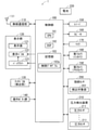
図3は電子機器1の電気的構成の一例を主に示すブロック図である。図3に示されるように、電子機器1は、制御部100、無線通信部110、表示部120、タッチパネル130及び操作ボタン群140を備える。さらに電子機器1は、レシーバ150、スピーカ160、マイク170、第1カメラ180、第2カメラ190、指紋センサ200、圧力検出装置210及び電池220を備える。電子機器1が備えるこれらの構成要素は、機器ケース11内に収められている。
<Example of electrical configuration of electronic devices>
FIG. 3 is a block diagram mainly showing an example of the electrical configuration of the electronic device 1. As shown in FIG. 3, the electronic device 1 includes a control unit 100, a wireless communication unit 110, a display unit 120, a touch panel 130, and an operation button group 140. Further, the electronic device 1 includes a receiver 150, a speaker 160, a microphone 170, a first camera 180, a second camera 190, a fingerprint sensor 200, a pressure detection device 210, and a battery 220. These components included in the electronic device 1 are housed in the device case 11.

制御部100は、電子機器1の他の構成要素を制御することによって、電子機器1の動作を統括的に管理することが可能である。制御部100は制御装置あるいは制御回路とも言える。制御部100は、以下にさらに詳細に述べられるように、種々の機能を実行するための制御及び処理能力を提供するために、少なくとも1つのプロセッサを含む。 The control unit 100 can comprehensively manage the operation of the electronic device 1 by controlling other components of the electronic device 1. The control unit 100 can also be said to be a control device or a control circuit. The control unit 100 includes at least one processor to provide control and processing power for performing various functions, as described in more detail below.

種々の実施形態によれば、少なくとも1つのプロセッサは、単一の集積回路(IC)として、または複数の通信可能に接続された集積回路(IC)及び/またはディスクリート回路(discrete circuits)として実行されてもよい。少なくとも1つのプロセッサは、種々の既知の技術に従って実行されることが可能である。 According to various embodiments, the at least one processor is performed as a single integrated circuit (IC) or as multiple communicable integrated circuits (ICs) and / or discrete circuits. You may. At least one processor can be run according to a variety of known techniques.

1つの実施形態において、プロセッサは、例えば、関連するメモリに記憶された指示を実行することによって1以上のデータ計算手続又は処理を実行するように構成された1以上の回路又はユニットを含む。他の実施形態において、プロセッサは、1以上のデータ計算手続き又は処理を実行するように構成されたファームウェア(例えば、ディスクリートロジックコンポーネント)であってもよい。 In one embodiment, the processor comprises, for example, one or more circuits or units configured to perform one or more data calculation procedures or processes by performing instructions stored in the associated memory. In other embodiments, the processor may be firmware (eg, a discrete logic component) configured to perform one or more data calculation procedures or processes.

種々の実施形態によれば、プロセッサは、1以上のプロセッサ、コントローラ、マイクロプロセッサ、マイクロコントローラ、特定用途向け集積回路(ASIC)、デジタル信号処理装置、プログラマブルロジックデバイス、フィールドプログラマブルゲートアレイ、またはこれらのデバイス若しくは構成の任意の組み合わせ、または他の既知のデバイス及び構成の組み合わせを含み、以下に説明される機能を実行してもよい。 According to various embodiments, the processor is one or more processors, controllers, microprocessors, microcontrollers, application specific integrated circuits (ASICs), digital signal processing devices, programmable logic devices, field programmable gate arrays, or these. Any combination of devices or configurations, or other known device and configuration combinations may be included to perform the functions described below.

本例では、制御部100は、CPU(Central Processing Unit)101、DSP(Digital Signal Processor)102及び記憶部103を備える。記憶部103は、ROM(Read Only Memory)及びRAM(Random Access Memory)などの、CPU101及びDSP102が読み取り可能な非一時的な記録媒体を含む。記憶部103が有するROMは、例えば、不揮発性メモリであるフラッシュROM(フラッシュメモリ)である。記憶部103には、電子機器1を制御するための複数の制御プログラム103a等が記憶されている。制御部100の各種機能は、CPU101及びDSP102が記憶部103内の各種制御プログラム103aを実行することによって実現される。 In this example, the control unit 100 includes a CPU (Central Processing Unit) 101, a DSP (Digital Signal Processor) 102, and a storage unit 103. The storage unit 103 includes a non-temporary recording medium such as a ROM (Read Only Memory) and a RAM (Random Access Memory) that can be read by the CPU 101 and the DSP 102. The ROM included in the storage unit 103 is, for example, a flash ROM (flash memory) which is a non-volatile memory. The storage unit 103 stores a plurality of control programs 103a and the like for controlling the electronic device 1. Various functions of the control unit 100 are realized by the CPU 101 and the DSP 102 executing various control programs 103a in the storage unit 103.

なお制御部100は、複数のCPU101を備えてもよい。また制御部100は、DSP102を備えなくてもよいし、複数のDSP102を備えてもよい。また、制御部100の全ての機能あるいは制御部100の一部の機能は、その機能の実現にソフトウェアが不要なハードウェア回路によって実現されてもよい。 The control unit 100 may include a plurality of CPUs 101. Further, the control unit 100 may not be provided with the DSP 102, or may be provided with a plurality of DSP 102. Further, all the functions of the control unit 100 or some functions of the control unit 100 may be realized by a hardware circuit that does not require software to realize the functions.

記憶部103は、ROM及びRAM以外の、コンピュータが読み取り可能な非一時的な記録媒体を備えていてもよい。記憶部103は、例えば、小型のハードディスクドライブ及びSSD(Solid State Drive)などを備えていてもよい。 The storage unit 103 may include a non-temporary recording medium other than ROM and RAM that can be read by a computer. The storage unit 103 may include, for example, a small hard disk drive, an SSD (Solid State Drive), or the like.

記憶部103内の複数の制御プログラム103aには、様々なアプリケーション(つまり、アプリケーションプログラム)が含まれている。記憶部103には、例えば、音声通話及びビデオ通話を行うための通話アプリケーション、ウェブサイトを表示するためのブラウザ、電子メールの作成、閲覧及び送受信を行うためのメールアプリケーションが記憶されている。また記憶部103には、第1カメラ180及び第2カメラ190を利用して被写体を撮影するためのカメラアプリケーション、記憶部103に記録されている静止画及び動画を表示するための記録画像表示アプリケーション、記憶部103に記憶されている音楽データの再生制御を行うための音楽再生制御アプリケーションなどが記憶されている。記憶部103内の少なくとも一つのアプリケーションは、記憶部103内にあらかじめ記憶されているものであってよい。また、記憶部103内の少なくとも一つのアプリケーションは、電子機器1が他の装置からダウンロードして記憶部103内に記憶したものであってよい。 The plurality of control programs 103a in the storage unit 103 include various applications (that is, application programs). The storage unit 103 stores, for example, a call application for making a voice call and a video call, a browser for displaying a website, and a mail application for creating, viewing, and transmitting / receiving an e-mail. Further, the storage unit 103 has a camera application for shooting a subject using the first camera 180 and the second camera 190, and a recorded image display application for displaying still images and moving images recorded in the storage unit 103. , A music reproduction control application for controlling reproduction of music data stored in the storage unit 103, and the like are stored. At least one application in the storage unit 103 may be stored in the storage unit 103 in advance. Further, at least one application in the storage unit 103 may be one that the electronic device 1 has downloaded from another device and stored in the storage unit 103.

無線通信部110は、アンテナ111を有している。無線通信部110は、アンテナ111を用いて、例えば複数種類の通信方式で無線通信することが可能である。無線通信部110の無線通信は、制御部100によって制御される。 The wireless communication unit 110 has an antenna 111. The wireless communication unit 110 can use the antenna 111 to perform wireless communication by, for example, a plurality of types of communication methods. The wireless communication of the wireless communication unit 110 is controlled by the control unit 100.

無線通信部110は、携帯電話システムの基地局と無線通信することが可能である。無線通信部110は、当該基地局及びインターネット等のネットワークを通じて、電子機器1とは別の携帯電話機及びウェブサーバ等と通信することが可能である。電子機器1は、他の携帯電話機等と、データ通信、音声通話及びビデオ通話等を行うことが可能である。 The wireless communication unit 110 can wirelessly communicate with the base station of the mobile phone system. The wireless communication unit 110 can communicate with a mobile phone, a web server, or the like other than the electronic device 1 through the base station and a network such as the Internet. The electronic device 1 can perform data communication, voice call, video call, and the like with another mobile phone and the like.

また無線通信部110、Wifi等の無線LAN(Local Area Network)を用いて無線通信を行うことが可能である。また無線通信部110は、近距離無線通信を行うことが可能である。例えば、無線通信部110は、Bluetooth(登録商標)に準拠して無線通信することが可能である。無線通信部110は、ZigBee(登録商標)及びNFC(Near Field Communication)の少なくとも一方に準拠して無線通信することが可能であってもよい。 Further, wireless communication can be performed using a wireless LAN (Local Area Network) such as the wireless communication unit 110 and Wifi. Further, the wireless communication unit 110 can perform short-range wireless communication. For example, the wireless communication unit 110 can perform wireless communication in accordance with Bluetooth (registered trademark). The wireless communication unit 110 may be capable of wireless communication in accordance with at least one of ZigBee (registered trademark) and NFC (Near Field Communication).

無線通信部110は、アンテナ111で受信した信号に対して増幅処理等の各種処理を行い、処理後の受信信号を制御部100に出力する。制御部100は、入力される受信信号に対して各種処理を行って、当該受信信号に含まれる情報を取得する。また、制御部100は、情報を含む送信信号を無線通信部110に出力する。無線通信部110は、入力される送信信号に対して増幅処理等の各種処理を行って、処理後の送信信号をアンテナ111から無線送信する。 The wireless communication unit 110 performs various processing such as amplification processing on the signal received by the antenna 111, and outputs the processed reception signal to the control unit 100. The control unit 100 performs various processes on the input received signal to acquire the information included in the received signal. Further, the control unit 100 outputs a transmission signal including information to the wireless communication unit 110. The wireless communication unit 110 performs various processing such as amplification processing on the input transmission signal, and wirelessly transmits the processed transmission signal from the antenna 111.

表示部120は、電子機器1の前面に位置する表示面121と、表示パネル122と、バックライト123とを備えている。表示部120は、表示面121に各種情報を表示することが可能である。表示パネル122は、例えば、液晶表示パネルであって、複数の画素(「画素部」あるいは「画素回路」とも呼ばれる)を備える。表示パネル122は、例えば、液晶、ガラス基板及び偏光板等を備える。表示パネル122は、機器ケース11内において、表示面121と対向している。表示部120に表示される情報は、電子機器1の表面の表示面121に表示される。バックライト123は、表示パネル122の裏側から当該表示パネル122に対して光を照射する。バックライト123は、例えば、少なくとも一つのLED(発光ダイオード)を備える。表示パネル122は、制御部100によって制御されることにより、画素単位で、バックライト123からの光の透過量を制御することが可能である。これにより、表示パネル122は、各種情報を表示することが可能である。バックライト123が点灯しているときに表示パネル122の各画素が制御部100によって制御されることにより、表示部120は、文字、記号及び図形などの各種情報を表示することが可能である。制御部100は、バックライト123を制御することが可能である。制御部100は、例えば、バックライト123を点灯させたり、消灯させたりすることが可能である。 The display unit 120 includes a display surface 121 located on the front surface of the electronic device 1, a display panel 122, and a backlight 123. The display unit 120 can display various information on the display surface 121. The display panel 122 is, for example, a liquid crystal display panel and includes a plurality of pixels (also referred to as a “pixel unit” or a “pixel circuit”). The display panel 122 includes, for example, a liquid crystal display, a glass substrate, a polarizing plate, and the like. The display panel 122 faces the display surface 121 in the device case 11. The information displayed on the display unit 120 is displayed on the display surface 121 on the surface of the electronic device 1. The backlight 123 irradiates the display panel 122 with light from the back side of the display panel 122. The backlight 123 includes, for example, at least one LED (light emitting diode). The display panel 122 can be controlled by the control unit 100 to control the amount of light transmitted from the backlight 123 on a pixel-by-pixel basis. As a result, the display panel 122 can display various types of information. Since each pixel of the display panel 122 is controlled by the control unit 100 when the backlight 123 is lit, the display unit 120 can display various information such as characters, symbols, and figures. The control unit 100 can control the backlight 123. The control unit 100 can turn on or off the backlight 123, for example.

なお表示パネル122は、液晶表示パネル以外の表示パネルであってもよい。例えば、表示パネル122は、有機EL(Electroluminescence)パネルなどの自発光型の表示パネルであってもよい。この場合には、バックライト123は不要になる。 The display panel 122 may be a display panel other than the liquid crystal display panel. For example, the display panel 122 may be a self-luminous display panel such as an organic EL (Electroluminescence) panel. In this case, the backlight 123 becomes unnecessary.

タッチパネル130は、表示面121に対する指等の操作子による操作を検出することが可能である。タッチパネル130は、表示面121に対する操作入力を検出する検出部であるとも言える。タッチパネル130は、例えば、投影型静電容量方式のタッチパネルである。タッチパネル130は、例えば、表示面121の裏側に位置する。ユーザが指等の操作子によって表示面121に対して操作を行ったとき、その操作に応じた電気信号をタッチパネル130は制御部100に入力することが可能である。制御部100は、タッチパネル130からの電気信号(出力信号)に基づいて、表示面121に対して行われた操作の内容を特定することが可能である。そして制御部100は、特定した操作内容に応じた処理を行うことが可能である。これにより、制御部100は、タッチパネル130で検出された操作入力に応じた処理を行うことが可能である。なお、表示パネル122及びタッチパネル130の代わりに、タッチパネルが組み込まれたインセル型の表示パネルが採用されてもよい。この場合には、当該表示パネルは、表示面121に対する操作入力を検出する検出部としても機能する。 The touch panel 130 can detect an operation by an operator such as a finger on the display surface 121. It can be said that the touch panel 130 is a detection unit that detects an operation input to the display surface 121. The touch panel 130 is, for example, a projection type capacitance type touch panel. The touch panel 130 is located, for example, on the back side of the display surface 121. When the user performs an operation on the display surface 121 with an operator such as a finger, the touch panel 130 can input an electric signal corresponding to the operation to the control unit 100. The control unit 100 can specify the content of the operation performed on the display surface 121 based on the electric signal (output signal) from the touch panel 130. Then, the control unit 100 can perform processing according to the specified operation content. As a result, the control unit 100 can perform processing according to the operation input detected by the touch panel 130. Instead of the display panel 122 and the touch panel 130, an in-cell type display panel incorporating a touch panel may be adopted. In this case, the display panel also functions as a detection unit for detecting an operation input to the display surface 121.

操作ボタン群140の各操作ボタンは、ユーザによって操作されると、操作されたことを示す操作信号を制御部100に出力することが可能である。これにより、制御部100は、各操作ボタンについて、当該操作ボタンが操作されたか否かを判断することができる。操作信号が入力された制御部100が他の構成要素を制御することによって、電子機器1では、操作された操作ボタンに割り当てられている機能が実行される。 When each operation button of the operation button group 140 is operated by the user, it is possible to output an operation signal indicating that the operation has been performed to the control unit 100. As a result, the control unit 100 can determine whether or not the operation button has been operated for each operation button. When the control unit 100 to which the operation signal is input controls other components, the electronic device 1 executes the function assigned to the operated operation button.

マイク170は、電子機器1の外部から入力される音を電気的な音信号に変換して制御部100に出力することが可能である。電子機器1の外部からの音は、マイク穴14から電子機器1の内部に取り込まれてマイク170に入力される。 The microphone 170 can convert a sound input from the outside of the electronic device 1 into an electrical sound signal and output it to the control unit 100. The sound from the outside of the electronic device 1 is taken into the inside of the electronic device 1 through the microphone hole 14 and input to the microphone 170.

スピーカ160は、例えばダイナミックスピーカである。スピーカ160は、制御部100からの電気的な音信号を音に変換して出力することが可能である。スピーカ160から出力される音は、スピーカ穴13から外部に出力される。ユーザは、スピーカ穴13から出力される音を、電子機器1から離れた場所でも聞こえることが可能である。 The speaker 160 is, for example, a dynamic speaker. The speaker 160 can convert an electrical sound signal from the control unit 100 into sound and output it. The sound output from the speaker 160 is output to the outside through the speaker hole 13. The user can hear the sound output from the speaker hole 13 even at a place away from the electronic device 1.

レシーバ150は受話音を出力することが可能である。レシーバ150は例えばダイナミックスピーカである。レシーバ150は、制御部100からの電気的な音信号を音に変換して出力することが可能である。レシーバ150から出力される音はレシーバ穴12から外部に出力される。レシーバ穴12から出力される音の音量は、スピーカ穴13から出力される音の音量よりも小さくなっている。ユーザは、レシーバ穴12から出力される音を、当該レシーバ穴12に耳を近づけることによって聞くことができる。なお、レシーバ150の代わりに、機器ケース11の前面部分を振動させる、圧電振動素子等の振動素子を設けてもよい。この場合には、音は、当該前面部分の振動によりユーザに伝達される。 The receiver 150 can output the received sound. The receiver 150 is, for example, a dynamic speaker. The receiver 150 can convert an electrical sound signal from the control unit 100 into sound and output it. The sound output from the receiver 150 is output to the outside through the receiver hole 12. The volume of the sound output from the receiver hole 12 is lower than the volume of the sound output from the speaker hole 13. The user can hear the sound output from the receiver hole 12 by bringing his / her ear close to the receiver hole 12. Instead of the receiver 150, a vibration element such as a piezoelectric vibration element that vibrates the front surface portion of the device case 11 may be provided. In this case, the sound is transmitted to the user by the vibration of the front portion.

第1カメラ180は、レンズ181及びイメージセンサなどを備えている。第2カメラ190は、レンズ191及びイメージセンサなどを備えている。第1カメラ180及び第2カメラ190のそれぞれは、制御部100による制御に基づいて被写体を撮影し、撮影した被写体を示す静止画あるいは動画を生成して制御部100に出力することが可能である。 The first camera 180 includes a lens 181 and an image sensor. The second camera 190 includes a lens 191 and an image sensor. Each of the first camera 180 and the second camera 190 can shoot a subject based on the control by the control unit 100, generate a still image or a moving image showing the shot subject, and output it to the control unit 100. ..

第1カメラ180のレンズ181は、機器ケース11の前面11aから視認可能となっている。したがって、第1カメラ180は、電子機器1の前面側(言い換えれば、表示面121側)に存在する被写体を撮影することが可能である。第1カメラ180はインカメラと呼ばれる。一方で、第2カメラ190のレンズ191は、機器ケース11の背面11bから視認可能となっている。したがって、第2カメラ190は、電子機器1の背面側に存在する被写体を撮影することが可能である。第2カメラ190はアウトカメラと呼ばれる。 The lens 181 of the first camera 180 is visible from the front surface 11a of the device case 11. Therefore, the first camera 180 can photograph a subject existing on the front side (in other words, the display surface 121 side) of the electronic device 1. The first camera 180 is called an in-camera. On the other hand, the lens 191 of the second camera 190 is visible from the back surface 11b of the device case 11. Therefore, the second camera 190 can capture a subject existing on the back side of the electronic device 1. The second camera 190 is called an out-camera.

指紋センサ200は、検出対象面201にさわる指の指紋を検出することが可能である。そして、指紋センサ200は、検出した指紋を示す指紋情報を制御部100に出力することが可能である。 The fingerprint sensor 200 can detect the fingerprint of the finger touching the detection target surface 201. Then, the fingerprint sensor 200 can output the fingerprint information indicating the detected fingerprint to the control unit 100.

ここで、検出対象面201に指がさわることには、検出対象面201に対して指が軽くくっつくことと、検出対象面201を指が押すこと(言い換えれば検出対象面201を指が押圧すること)の両方を含む。したがって、指紋センサ200は、指が検出対象面201に軽くくっついている場合に当該指の指紋を検出することができる。また指紋センサ200は、指によって検出対象面201が押されている場合に当該指の指紋を検出することができる。指紋センサ200は、検出対象面201を指が弱く押す場合であっても、指が強く押す場合であっても、当該指の指紋を検出することができる。指紋センサ200での指紋検出方式は、例えば、静電容量方式である。指紋センサ200での指紋検出方式は、静電容量方式以外の方式であってもよい。例えば、指紋センサ200での指紋検出方式は光学式であってもよい。制御部100は、後述するように、指紋センサ200での指紋検出結果に基づいて処理を行うことが可能である。以後、指紋センサ200で検出された指紋を「検出指紋」と呼ぶことがある。また、指紋センサ200から出力される指紋情報を「検出指紋情報」と呼ぶことがある。また、単に指紋検出結果と言えば、指紋センサ200での指紋検出結果を意味する。 Here, when the finger touches the detection target surface 201, the finger lightly sticks to the detection target surface 201 and the finger presses the detection target surface 201 (in other words, the finger presses the detection target surface 201). That) includes both. Therefore, the fingerprint sensor 200 can detect the fingerprint of the finger when the finger is lightly attached to the detection target surface 201. Further, the fingerprint sensor 200 can detect the fingerprint of the finger when the detection target surface 201 is pressed by the finger. The fingerprint sensor 200 can detect the fingerprint of the finger regardless of whether the finger weakly presses the detection target surface 201 or the finger strongly presses the detection target surface 201. The fingerprint detection method of the fingerprint sensor 200 is, for example, a capacitance method. The fingerprint detection method of the fingerprint sensor 200 may be a method other than the capacitance method. For example, the fingerprint detection method in the fingerprint sensor 200 may be an optical method. As will be described later, the control unit 100 can perform processing based on the fingerprint detection result of the fingerprint sensor 200. Hereinafter, the fingerprint detected by the fingerprint sensor 200 may be referred to as a "detected fingerprint". Further, the fingerprint information output from the fingerprint sensor 200 may be referred to as "detection fingerprint information". Further, the fingerprint detection result simply means the fingerprint detection result of the fingerprint sensor 200.

圧力検出装置210は、検出対象面201にかかる圧力を検出することが可能である。圧力検出装置210は、例えば、検出対象面201に指がさわるときの当該検出対象面201にかかる圧力を検出することが可能である。圧力検出装置210は複数の圧力センサ211を備えている。各圧力センサ211は、検出対象面201にかかる圧力を検出することが可能である。圧力検出装置210での圧力検出結果は、検出対象面201での圧力がかかる位置に応じて変化する。具体的には、圧力検出装置210では、複数の圧力センサ211で検出される圧力の関係が、検出対象面201での圧力がかかる位置に応じて変化する。制御部100は、後述するように、圧力検出装置210での圧力検出結果に基づいて処理を行うことが可能である。例えば、制御部100は、圧力検出装置210での圧力検出結果に基づいて、検出対象面201に対する操作を特定することが可能である。以後、圧力センサ211で検出された圧力を「検出圧力」と呼ぶことがある。また、単に圧力検出結果と言えば、圧力検出装置210での圧力検出結果を意味する。 The pressure detection device 210 can detect the pressure applied to the detection target surface 201. The pressure detecting device 210 can detect, for example, the pressure applied to the detection target surface 201 when the finger touches the detection target surface 201. The pressure detection device 210 includes a plurality of pressure sensors 211. Each pressure sensor 211 can detect the pressure applied to the detection target surface 201. The pressure detection result of the pressure detection device 210 changes depending on the position where the pressure is applied on the detection target surface 201. Specifically, in the pressure detection device 210, the relationship between the pressures detected by the plurality of pressure sensors 211 changes according to the position where the pressure is applied on the detection target surface 201. As will be described later, the control unit 100 can perform processing based on the pressure detection result of the pressure detection device 210. For example, the control unit 100 can specify an operation on the detection target surface 201 based on the pressure detection result of the pressure detection device 210. Hereinafter, the pressure detected by the pressure sensor 211 may be referred to as "detected pressure". Further, the pressure detection result simply means the pressure detection result in the pressure detection device 210.

電池220は電子機器1の電源を出力することが可能である。電池220は例えば充電式の電池である。電池220から出力される電源は、電子機器1が備える制御部100及び無線通信部110などの各種構成に対して供給される。 The battery 220 can output the power supply of the electronic device 1. The battery 220 is, for example, a rechargeable battery. The power output from the battery 220 is supplied to various configurations such as the control unit 100 and the wireless communication unit 110 included in the electronic device 1.

なお電子機器1は、タッチパネル130、指紋センサ200及び圧力検出装置210以外のセンサを備えてもよい。例えば、電子機器1は、加速度センサ、気圧センサ、地磁気センサ、温度センサ、近接センサ、照度センサ、ジャイロセンサ及び位置検出センサの少なくとも一つを備えてもよい。 The electronic device 1 may include a sensor other than the touch panel 130, the fingerprint sensor 200, and the pressure detection device 210. For example, the electronic device 1 may include at least one of an acceleration sensor, a pressure sensor, a geomagnetic sensor, a temperature sensor, a proximity sensor, an illuminance sensor, a gyro sensor, and a position detection sensor.

以下では、主に、表示面121及び検出対象面201が指で操作される場合の電子機器1の動作について説明する。 Hereinafter, the operation of the electronic device 1 when the display surface 121 and the detection target surface 201 are operated by a finger will be mainly described.

<指紋センサ及び複数の圧力センサの配置例>
図4は、電子機器1の機器ケース11内における、指紋センサ200付近の構造の一例を示す平面図である。図5は、図4に示される構造の矢視A−Aにおける断面構造を示す図である。
<Example of arrangement of fingerprint sensor and multiple pressure sensors>
FIG. 4 is a plan view showing an example of a structure near the fingerprint sensor 200 in the device case 11 of the electronic device 1. FIG. 5 is a diagram showing a cross-sectional structure of the structure shown in FIG. 4 in arrow view AA.

図4及び5に示されるように、機器ケース11内には、フレキシブル基板250が位置している。指紋センサ200と、圧力検出装置210を構成する複数の圧力センサ211とは、フレキシブル基板250に実装されている。 As shown in FIGS. 4 and 5, the flexible substrate 250 is located in the equipment case 11. The fingerprint sensor 200 and the plurality of pressure sensors 211 constituting the pressure detection device 210 are mounted on the flexible substrate 250.

フレキシブル基板250は、第1主面251と、それとは反対側の第2主面252とを備えている。第1主面251は前面11a側に位置し、第2主面252は背面11b側に位置する。 The flexible substrate 250 includes a first main surface 251 and a second main surface 252 on the opposite side thereof. The first main surface 251 is located on the front surface 11a side, and the second main surface 252 is located on the back surface 11b side.

指紋センサ200は第1主面251上に位置する。指紋センサ200から出力される信号は、フレキシブル基板250が備える信号配線を通じて制御部100に入力される。 The fingerprint sensor 200 is located on the first main surface 251. The signal output from the fingerprint sensor 200 is input to the control unit 100 through the signal wiring included in the flexible substrate 250.

圧力検出装置210は、例えば4つの圧力センサ211a〜211dを備えている。圧力センサ211a〜211dは、フレキシブル基板250の第2主面252に位置している。圧力センサ211a〜211dから出力される信号は、フレキシブル基板250が備える信号配線を通じて制御部100に入力される。 The pressure detection device 210 includes, for example, four pressure sensors 211a to 211d. The pressure sensors 211a to 211d are located on the second main surface 252 of the flexible substrate 250. The signals output from the pressure sensors 211a to 211d are input to the control unit 100 through the signal wiring included in the flexible substrate 250.

圧力センサ211aは、例えば、フレキシブル基板250の第2主面252側から平面透視したときに、指紋センサ200の検出対象面201の左上部分201aと部分的に重なるように位置する。図5を用いて説明すると、圧力センサ211aは、矢印270が示す方向から平面透視したときに、検出対象面201の左上部分201aと部分的に重なるように位置する。言い換えれば、圧力センサ211aは、電子機器1の厚み方向(言い換えれば、表示面121に垂直な方向)において、フレキシブル基板250を介して、検出対象面201の左上部分201aと部分的に対向するように位置する。圧力センサ211bは、例えば、第2主面252側から平面透視したときに、検出対象面201の左下部分201bと部分的に重なるように位置する。圧力センサ211cは、例えば、第2主面252側から平面透視したときに、検出対象面201の右上部分201cと部分的に重なるように位置する。圧力センサ211dは、例えば、第2主面252側から平面透視したときに、検出対象面201の右下部分201dと部分的に重なるように位置する。 The pressure sensor 211a is located, for example, so as to partially overlap the upper left portion 201a of the detection target surface 201 of the fingerprint sensor 200 when viewed in a plane from the second main surface 252 side of the flexible substrate 250. Explaining with reference to FIG. 5, the pressure sensor 211a is positioned so as to partially overlap the upper left portion 201a of the detection target surface 201 when viewed in a plane from the direction indicated by the arrow 270. In other words, the pressure sensor 211a partially faces the upper left portion 201a of the detection target surface 201 via the flexible substrate 250 in the thickness direction of the electronic device 1 (in other words, the direction perpendicular to the display surface 121). Located in. The pressure sensor 211b is located, for example, so as to partially overlap the lower left portion 201b of the detection target surface 201 when viewed in a plane from the second main surface 252 side. The pressure sensor 211c is located, for example, so as to partially overlap the upper right portion 201c of the detection target surface 201 when viewed in a plane from the second main surface 252 side. The pressure sensor 211d is located, for example, so as to partially overlap the lower right portion 201d of the detection target surface 201 when viewed in a plane from the second main surface 252 side.

このように配置された複数の圧力センサ211a〜211dを備える圧力検出装置210では、圧力センサ211a〜211dの検出圧力の関係が、検出対象面201での圧力がかかる位置に応じて変化する。 In the pressure detection device 210 including the plurality of pressure sensors 211a to 211d arranged in this way, the relationship between the detection pressures of the pressure sensors 211a to 211d changes depending on the position where the pressure is applied on the detection target surface 201.

例えば、検出対象面201の左上部分201aに圧力がかかる場合、圧力センサ211a〜211dの検出圧力において、圧力センサ211aの検出圧力が最大となる。検出対象面201の左下部分201bに圧力がかかる場合、圧力センサ211a〜211dの検出圧力において、圧力センサ211bの検出圧力が最大となる。検出対象面201の右上部分201cに圧力がかかる場合、圧力センサ211a〜211dの検出圧力において、圧力センサ211cの検出圧力が最大となる。検出対象面201の右下部分201dに圧力がかかる場合、圧力センサ211a〜211dの検出圧力において、圧力センサ211dの検出圧力が最大となる。 For example, when pressure is applied to the upper left portion 201a of the detection target surface 201, the detection pressure of the pressure sensor 211a becomes the maximum in the detection pressures of the pressure sensors 211a to 211d. When pressure is applied to the lower left portion 201b of the detection target surface 201, the detection pressure of the pressure sensor 211b becomes the maximum in the detection pressures of the pressure sensors 211a to 211d. When pressure is applied to the upper right portion 201c of the detection target surface 201, the detection pressure of the pressure sensor 211c becomes the maximum at the detection pressure of the pressure sensors 211a to 211d. When pressure is applied to the lower right portion 201d of the detection target surface 201, the detection pressure of the pressure sensor 211d becomes the maximum in the detection pressures of the pressure sensors 211a to 211d.

また、検出対象面201の中心201eに圧力がかかる場合、圧力センサ211a〜211dの検出圧力がほぼ同じになる。検出対象面201の左中央部分201fに圧力がかかる場合、圧力センサ211a及び211bの検出圧力が、圧力センサ211c及び211dの検出圧力よりも大きくなり、圧力センサ211a及び211bの検出圧力がほぼ同じになり、圧力センサ211c及び211dの検出圧力がほぼ同じになる。検出対象面201の右中央部分201gに圧力がかかる場合、圧力センサ211c及び211dの検出圧力が、圧力センサ211a及び211bの検出圧力よりも大きくなり、圧力センサ211a及び211bの検出圧力がほぼ同じになり、圧力センサ211c及び211dの検出圧力がほぼ同じになる。検出対象面201の上中央部分201hに圧力がかかる場合、圧力センサ211a及び211cの検出圧力が、圧力センサ211b及び211dの検出圧力よりも大きくなり、圧力センサ211a及び211cの検出圧力がほぼ同じになり、圧力センサ211b及び211dの検出圧力がほぼ同じになる。検出対象面201の下中央部分201iに圧力がかかる場合、圧力センサ211b及び211dの検出圧力が、圧力センサ211a及び211cの検出圧力よりも大きくなり、圧力センサ211a及び211cの検出圧力がほぼ同じになり、圧力センサ211b及び211dの検出圧力がほぼ同じになる。 Further, when pressure is applied to the center 201e of the detection target surface 201, the detection pressures of the pressure sensors 211a to 211d are substantially the same. When pressure is applied to the left central portion 201f of the detection target surface 201, the detection pressures of the pressure sensors 211a and 211b become larger than the detection pressures of the pressure sensors 211c and 211d, and the detection pressures of the pressure sensors 211a and 211b become almost the same. Therefore, the detected pressures of the pressure sensors 211c and 211d are almost the same. When pressure is applied to the right center portion 201g of the detection target surface 201, the detection pressures of the pressure sensors 211c and 211d become larger than the detection pressures of the pressure sensors 211a and 211b, and the detection pressures of the pressure sensors 211a and 211b become almost the same. Therefore, the detected pressures of the pressure sensors 211c and 211d are almost the same. When pressure is applied to the upper central portion 201h of the detection target surface 201, the detection pressures of the pressure sensors 211a and 211c become larger than the detection pressures of the pressure sensors 211b and 211d, and the detection pressures of the pressure sensors 211a and 211c become almost the same. Therefore, the detected pressures of the pressure sensors 211b and 211d are almost the same. When pressure is applied to the lower central portion 201i of the detection target surface 201, the detection pressures of the pressure sensors 211b and 211d become larger than the detection pressures of the pressure sensors 211a and 211c, and the detection pressures of the pressure sensors 211a and 211c become almost the same. Therefore, the detected pressures of the pressure sensors 211b and 211d are almost the same.

なお、圧力センサ211aは、フレキシブル基板250の第2主面252側から平面透視したときに、指紋センサ200の検出対象面201の左上部分201aと完全に重なっていてもよいし、完全に重なっていなくてもよい。他の圧力センサ211b〜211dについても同様である。 The pressure sensor 211a may or may not completely overlap the upper left portion 201a of the detection target surface 201 of the fingerprint sensor 200 when viewed in a plane from the second main surface 252 side of the flexible substrate 250. It does not have to be. The same applies to the other pressure sensors 211b to 211d.

図5に示されるように、電子機器1は、機器ケース11内において、圧力センサ211a〜211dと機器ケース11との間の隙間を無くすための部材260を備えている。部材260は、圧力センサ211a〜211dと、機器ケース11との間の隙間を埋めるように、圧力センサ211a〜211dと、機器ケース11の背面部分11Bとの間に位置する。部材260には、樹脂部材が含まれてもよいし、金属部材が含まれてもよいし、電子部品が含まれてもよい。 As shown in FIG. 5, the electronic device 1 includes a member 260 in the device case 11 for eliminating a gap between the pressure sensors 211a to 211d and the device case 11. The member 260 is located between the pressure sensors 211a to 211d and the back surface portion 11B of the equipment case 11 so as to fill the gap between the pressure sensors 211a to 211d and the equipment case 11. The member 260 may include a resin member, a metal member, or an electronic component.

このような部材260が存在することによって、圧力センサ211a〜211dにかかる圧力が逃げる可能性を低減することができる。その結果、圧力センサ211a〜211dは、検出対象面201にかかる圧力を適切に検出することができる。なお、電子機器1は部材260を備えていなくてよい。この場合、機器ケース11の背面部分11Bの少なくとも一部が、圧力センサ211a〜211dまで延びてそれらを支持してもよい。この場合であっても、圧力センサ211a〜211dにかかる圧力が逃げる可能性を低減することができる。 The presence of such a member 260 can reduce the possibility that the pressure applied to the pressure sensors 211a to 211d escapes. As a result, the pressure sensors 211a to 211d can appropriately detect the pressure applied to the detection target surface 201. The electronic device 1 does not have to include the member 260. In this case, at least a part of the back surface portion 11B of the device case 11 may extend to the pressure sensors 211a to 211d to support them. Even in this case, the possibility that the pressure applied to the pressure sensors 211a to 211d escapes can be reduced.

<電子機器の動作モードの一例>
電子機器1は多数の動作モードを有している。電子機器1の動作モードには、例えば、通常モード、スリープモード及びシャットダウンモードが含まれる。シャットダウンモードでは、電子機器1がシャットダウンし、電子機器1のほとんどの機能が停止する。スリープモードでは、電子機器1における、表示機能を含む一部の機能が停止する。通常モードは、電子機器1がスリープモード及びシャットダウンモード以外で動作している状態を意味する。制御部100が、設定すべき動作モードに応じて電子機器1の所定の構成を制御することによって、電子機器1の動作モードが設定される。
<Example of operation mode of electronic device>
The electronic device 1 has a large number of operation modes. The operation mode of the electronic device 1 includes, for example, a normal mode, a sleep mode, and a shutdown mode. In the shutdown mode, the electronic device 1 shuts down and most of the functions of the electronic device 1 are stopped. In the sleep mode, some functions including the display function in the electronic device 1 are stopped. The normal mode means a state in which the electronic device 1 is operating in a mode other than the sleep mode and the shutdown mode. The operation mode of the electronic device 1 is set by the control unit 100 controlling a predetermined configuration of the electronic device 1 according to the operation mode to be set.

スリープモードでは、例えば、表示パネル122、バックライト123、タッチパネル130、第1カメラ180及び第2カメラ190等を含む電子機器1の一部の構成が動作しない。シャットダウンモードでは、表示パネル122、バックライト123、タッチパネル130、第1カメラ180及び第2カメラ190等を含む電子機器1のほとんどの構成が動作しない。スリープモードでは、通常モードよりも電子機器1の消費電力が低減する。シャットダウンモードでは、スリープモードよりも電子機器1の消費電力が低減する。 In the sleep mode, for example, some configurations of the electronic device 1 including the display panel 122, the backlight 123, the touch panel 130, the first camera 180, the second camera 190, and the like do not operate. In the shutdown mode, most configurations of the electronic device 1 including the display panel 122, the backlight 123, the touch panel 130, the first camera 180, the second camera 190, and the like do not operate. In the sleep mode, the power consumption of the electronic device 1 is reduced as compared with the normal mode. In the shutdown mode, the power consumption of the electronic device 1 is reduced as compared with the sleep mode.

また、スリープモード及びシャットダウンモードでは、表示面121は非表示状態となる。ここで、表示状態とは、電子機器1が意図的に表示面121に表示を行っている状態を意味する。また非表示状態とは、電子機器1が意図的に表示面121に表示を行うことを実行してない状態を意味する。本例では、バックライト123が消灯すると、電子機器1は、意図的に表示面121に表示を行うことができない。したがって、バックライト123が消灯することによって、表示面121が非表示状態となる。言い換えれば、バックライト123が駆動されていないときに、表示面121が非表示状態となる。また、表示パネル122が有機ELパネル等の自発光型の表示パネルである場合には、全画素が発光していない場合に表示面121が非表示状態となる。つまり、表示パネル122の表示領域の全領域が消灯状態の場合に表示面121が非表示状態となる。 Further, in the sleep mode and the shutdown mode, the display surface 121 is in a non-display state. Here, the display state means a state in which the electronic device 1 intentionally displays on the display surface 121. Further, the non-display state means a state in which the electronic device 1 intentionally does not perform display on the display surface 121. In this example, when the backlight 123 is turned off, the electronic device 1 cannot intentionally display on the display surface 121. Therefore, when the backlight 123 is turned off, the display surface 121 is in a non-display state. In other words, the display surface 121 is in a non-display state when the backlight 123 is not driven. Further, when the display panel 122 is a self-luminous display panel such as an organic EL panel, the display surface 121 is in a non-display state when all the pixels do not emit light. That is, when the entire display area of the display panel 122 is in the off state, the display surface 121 is in the non-display state.

本例では、通常モードにおいて、電源ボタン141が長時間押されると、通常モードからシャットダウンモードに遷移させるか否かをユーザに確認するための確認画面が表示面121に表示される。表示面121に確認画面が表示されている状態において、ユーザが表示面121に対して所定の操作を行うと、通常モードからシャットダウンモードに遷移する。 In this example, when the power button 141 is pressed for a long time in the normal mode, a confirmation screen for confirming with the user whether or not to transition from the normal mode to the shutdown mode is displayed on the display surface 121. When the user performs a predetermined operation on the display surface 121 while the confirmation screen is displayed on the display surface 121, the mode transitions from the normal mode to the shutdown mode.

また通常モードにおいて、電子機器1に対して一定時間以上操作が行われなければ、通常モードからスリープモードに遷移する。また、通常モードにおいて、電源ボタン141が短時間押されると、通常モードからスリープモードに遷移する。 Further, in the normal mode, if the electronic device 1 is not operated for a certain period of time or longer, the mode transitions from the normal mode to the sleep mode. Further, in the normal mode, when the power button 141 is pressed for a short time, the mode transitions from the normal mode to the sleep mode.

一方で、スリープモードにおいて、電源ボタン141が短時間押されたとき、スリープモードから通常モードに遷移する。つまり、スリープモードにおいて、電源ボタン141が短時間押されたとき、電子機器1では、スリープモードに遷移するときに停止された機能が復帰する。本例では、通常モードには、後述するロックモードが含まれている。スリープモードにおいて、電源ボタン141が短時間押されたとき、スリープモードからロックモードに遷移する。また、後述するように、スリープモードにおいて、ユーザ認証に成功したとき、スリープモードから通常モードに遷移する。 On the other hand, in the sleep mode, when the power button 141 is pressed for a short time, the mode transitions from the sleep mode to the normal mode. That is, when the power button 141 is pressed for a short time in the sleep mode, the function stopped when the electronic device 1 transitions to the sleep mode is restored. In this example, the normal mode includes a lock mode described later. In the sleep mode, when the power button 141 is pressed for a short time, the sleep mode is changed to the lock mode. Further, as will be described later, in the sleep mode, when the user authentication is successful, the sleep mode is changed to the normal mode.

なお、以下に説明する、シャットダウンモード及びスリープモード以外の電子機器1の動作モードは、特に説明しなくても、通常モードに含まれる。また、単に動作モードと言えば、電子機器1の動作モードを意味する。 The operation modes of the electronic device 1 other than the shutdown mode and the sleep mode described below are included in the normal mode without any particular description. Further, the operation mode simply means the operation mode of the electronic device 1.

<表示面に表示される画面の一例>
通常モードにおいては、様々な画面が表示面121に表示される。表示面121に表示される画面は、表示面121に表示される画像であるとも言える。表示面121には、例えば、ホーム画面及びロック画面が表示される。図6はロック画面300の一例を示す図である。図7はホーム画面400の一例を示す図である。
<Example of screen displayed on the display surface>
In the normal mode, various screens are displayed on the display surface 121. It can be said that the screen displayed on the display surface 121 is an image displayed on the display surface 121. For example, a home screen and a lock screen are displayed on the display surface 121. FIG. 6 is a diagram showing an example of the lock screen 300. FIG. 7 is a diagram showing an example of the home screen 400.

図6に示されるように、ロック画面300には、例えば、現在の時刻301と、現在の日付302と、現在の曜日303とが示される。 As shown in FIG. 6, the lock screen 300 shows, for example, the current time 301, the current date 302, and the current day of the week 303.

ここで、通常モードには、記憶部103内の複数のアプリケーションのうち、特定のアプリケーション(例えば通話アプリケーション及びカメラアプリケーション)以外のアプリケーションを、ユーザが電子機器1に実行させることができないロックモードが含まれる。ロックモードは、画面ロックモードとも呼ばれる。ロックモードでは、ユーザは、記憶部103内の複数のアプリケーションのうち、特定のアプリケーション以外の各アプリケーションについて、当該アプリケーションの実行を電子機器1に指示することができない。ロック画面300は、電子機器1がロックモードであることを通知する画面であって、動作モードがロックモードのときに表示面121に表示される。なお、ロックモードでは、記憶部103内のすべてのアプリケーションをユーザが電子機器1に実行させることができなくてもよい。 Here, the normal mode includes a lock mode in which the user cannot cause the electronic device 1 to execute an application other than a specific application (for example, a call application and a camera application) among a plurality of applications in the storage unit 103. Is done. The lock mode is also called the screen lock mode. In the lock mode, the user cannot instruct the electronic device 1 to execute the application for each application other than the specific application among the plurality of applications in the storage unit 103. The lock screen 300 is a screen for notifying that the electronic device 1 is in the lock mode, and is displayed on the display surface 121 when the operation mode is the lock mode. In the lock mode, the user may not be able to execute all the applications in the storage unit 103 on the electronic device 1.

スリープモードにおいて、電源ボタン141が短時間押されたとき、スリープモードが解除されて、動作モードはロックモードとなる。これにより、表示面121にロック画面300が表示される。表示面121がロック画面300を表示している場合に、ユーザが電子機器1に対して所定の操作を行うと、電子機器1ではロックモードが解除されて、表示面121の表示はロック画面300から他の画面、例えばホーム画面400(図7参照)に遷移する。以後、通常モードにおいて、ロックモードが解除されている状態を「非ロックモード」と呼ぶことがある。 In the sleep mode, when the power button 141 is pressed for a short time, the sleep mode is released and the operation mode becomes the lock mode. As a result, the lock screen 300 is displayed on the display surface 121. When the user performs a predetermined operation on the electronic device 1 when the display surface 121 is displaying the lock screen 300, the lock mode is released on the electronic device 1, and the display on the display surface 121 is displayed on the lock screen 300. To another screen, for example, the home screen 400 (see FIG. 7). Hereinafter, in the normal mode, the state in which the lock mode is released may be referred to as a "non-lock mode".

また、ロック画面300だけに限らず、表示面121に表示される各画面には、電子機器1の状態を通知する通知領域500が含まれる。通知領域500は、ステータスバーとも呼ばれる。図6に示されるように、ロック画面300に含まれる通知領域500には、例えば、通信状態を示すアイコン(言い換えれば図形)501と、電池残量を示すアイコン502とが含まれる。一方で、ホーム画面400に含まれる通知領域500には、図7に示されるように、例えば、アイコン501及び502と、現在時刻を示すアイコン503とが含まれる。 Further, not only the lock screen 300 but also each screen displayed on the display surface 121 includes a notification area 500 for notifying the state of the electronic device 1. The notification area 500 is also called a status bar. As shown in FIG. 6, the notification area 500 included in the lock screen 300 includes, for example, an icon (in other words, a figure) 501 indicating a communication state and an icon 502 indicating the remaining battery level. On the other hand, the notification area 500 included in the home screen 400 includes, for example, icons 501 and 502 and icons 503 indicating the current time, as shown in FIG.

また、電子機器1において特定のイベントが発生すると、通知領域500には、発生したイベントに関する情報が示される。当該情報には、例えば、新しい電子メールの受信を通知するアイコン及び不在着信を通知するアイコンなどが含まれる。 Further, when a specific event occurs in the electronic device 1, the notification area 500 shows information about the event that has occurred. The information includes, for example, an icon notifying the receipt of new e-mail and an icon notifying the missed call.

図7に示されるように、ホーム画面400には、複数の操作ボタン401〜403が示される。操作ボタン401〜403のそれぞれはソフトウェアボタンである。操作ボタン401〜403は、非ロックモードにおいて、ホーム画面400以外の画面にも示される。 As shown in FIG. 7, a plurality of operation buttons 401 to 403 are shown on the home screen 400. Each of the operation buttons 401 to 403 is a software button. The operation buttons 401 to 403 are also shown on screens other than the home screen 400 in the non-lock mode.

操作ボタン401は例えばバックボタンである。バックボタンは、表示面121の表示を一つ前の表示に切り替えるための操作ボタンである。ユーザが操作ボタン401に対して所定の操作を行うことよって、表示面121の表示が一つ前の表示に切り替わる。例えば、ユーザが操作ボタン401に対してタップ操作を行うことよって、表示面121の表示が一つ前の表示に切り替わる。タップ操作は、指等の操作子が操作対象面を押してから、その押した箇所からすぐに離れる操作である。 The operation button 401 is, for example, a back button. The back button is an operation button for switching the display of the display surface 121 to the previous display. When the user performs a predetermined operation on the operation button 401, the display on the display surface 121 is switched to the previous display. For example, when the user taps the operation button 401, the display on the display surface 121 is switched to the previous display. The tap operation is an operation in which an operator such as a finger presses the operation target surface and then immediately leaves the pressed portion.

操作ボタン402は例えばホームボタンである。ホームボタンは、表示面121にホーム画面400を表示させるための操作ボタンである。ユーザが操作ボタン402に対して例えばタップ操作を行うことによって、表示面121にホーム画面が表示される。 The operation button 402 is, for example, a home button. The home button is an operation button for displaying the home screen 400 on the display surface 121. When the user taps the operation button 402, for example, the home screen is displayed on the display surface 121.

操作ボタン403は、例えば履歴ボタンである。履歴ボタンは、電子機器1で実行されたアプリケーションの履歴を表示面121に表示させるための操作ボタンである。ユーザが操作ボタン403に対して例えばタップ操作を行うことよって、表示面121には、電子機器1で実行されたアプリケーションの履歴が表示される。 The operation button 403 is, for example, a history button. The history button is an operation button for displaying the history of the application executed by the electronic device 1 on the display surface 121. When the user performs, for example, a tap operation on the operation button 403, the history of the application executed by the electronic device 1 is displayed on the display surface 121.

また、ホーム画面400には、記憶部103内のアプリケーションに対応し、対応するアプリケーションの実行を電子機器1に指示するためのアイコン405が示される。図7の例では、ホーム画面400に10個のアイコン405が示されている。ユーザは、アイコン405に対して所定の操作(例えばタップ操作)を行うことによって、当該アイコン450を選択することができる。制御部100は、選択されたアイコン405に対応するアプリケーションを記憶部103から読み出して実行する。つまり、制御部100は、タッチパネル130がアイコン405に対する所定の操作を検出すると、当該アイコン405に対応するアプリケーションを記憶部103から読み出して実行する。これにより、ユーザは、アイコン405を操作することによって当該アイコン405を選択し、選択したアイコン405に対応するアプリケーションを電子機器1に実行させることができる。例えば、ユーザが、ブラウザに対応するアイコン405をタップ操作すると、電子機器1ではブラウザが実行される。またユーザが、カメラアプリケーションに対応するアイコン405をタップ操作すると、電子機器1ではカメラアプリケーションが実行される。 Further, on the home screen 400, an icon 405 for instructing the electronic device 1 to execute the corresponding application corresponding to the application in the storage unit 103 is shown. In the example of FIG. 7, ten icons 405 are shown on the home screen 400. The user can select the icon 450 by performing a predetermined operation (for example, a tap operation) on the icon 405. The control unit 100 reads the application corresponding to the selected icon 405 from the storage unit 103 and executes it. That is, when the touch panel 130 detects a predetermined operation for the icon 405, the control unit 100 reads the application corresponding to the icon 405 from the storage unit 103 and executes it. As a result, the user can select the icon 405 by operating the icon 405 and cause the electronic device 1 to execute the application corresponding to the selected icon 405. For example, when the user taps the icon 405 corresponding to the browser, the browser is executed in the electronic device 1. When the user taps the icon 405 corresponding to the camera application, the camera application is executed in the electronic device 1.

ホーム画面400は、例えば複数のページで構成されている。図7には、ホーム画面400のあるページが示されている。各ページには、操作ボタン401〜403とアイコン405が示される。ホーム画面400を構成する複数のページは仮想的に左右方向に並べられている。ユーザが表示面121に対して左右方向のフリック操作あるいはスワイプ操作を行うと、表示面121には、隣のページが表示される。フリック操作は、指等の操作子が操作対象面を払う操作である。スワイプ操作は、指等の操作子が、操作対象面をさわった状態で、移動して停止する操作である。スワイプ操作はスライド操作とも呼ばれる。図8は、図7に示されるページとは別のページを示す図である。ホーム画面400の各ページは、表示面121に表示される一種の画面であると言える。 The home screen 400 is composed of, for example, a plurality of pages. FIG. 7 shows a page with a home screen 400. Operation buttons 401-403 and icons 405 are shown on each page. A plurality of pages constituting the home screen 400 are virtually arranged in the left-right direction. When the user performs a left-right flick operation or a swipe operation on the display surface 121, the adjacent page is displayed on the display surface 121. The flick operation is an operation in which an operator such as a finger pays the operation target surface. The swipe operation is an operation in which an operator such as a finger moves and stops while touching the operation target surface. The swipe operation is also called a slide operation. FIG. 8 is a diagram showing a page different from the page shown in FIG. 7. It can be said that each page of the home screen 400 is a kind of screen displayed on the display surface 121.

<指紋認証の一例>
動作モードが通常モードである場合、制御部100は、検出指紋情報に基づいて指紋認証を行うことが可能である。この指紋認証は、指紋検出結果に基づくユーザ認証であると言える。制御部100は、指紋認証を行う際、検出指紋情報、つまり、指紋センサ200で検出された指紋を示す指紋情報と、記憶部103に記憶されている基準指紋情報とを比較する。基準指紋情報は、正規ユーザ(例えば電子機器1の所有者)の指紋を示す指紋情報である。制御部100は、検出指紋情報と基準指紋情報とを比較した結果、両者が類似する場合には、指紋認証が成功であると判定する。つまり、制御部100は、検出指紋情報と基準指紋情報とが類似する場合には、指紋センサ200が検出した指紋を有するユーザが正規ユーザであると判定する。一方で、制御部100は、検出指紋情報と基準指紋情報とが類似しない場合には、指紋認証に失敗したと判定する。つまり、制御部100は、指紋センサ200が検出した指紋を有するユーザが非正規ユーザであると判定する。
<Example of fingerprint authentication>
When the operation mode is the normal mode, the control unit 100 can perform fingerprint authentication based on the detected fingerprint information. It can be said that this fingerprint authentication is user authentication based on the fingerprint detection result. When performing fingerprint authentication, the control unit 100 compares the detected fingerprint information, that is, the fingerprint information indicating the fingerprint detected by the fingerprint sensor 200 with the reference fingerprint information stored in the storage unit 103. The reference fingerprint information is fingerprint information indicating the fingerprint of a legitimate user (for example, the owner of the electronic device 1). As a result of comparing the detected fingerprint information and the reference fingerprint information, the control unit 100 determines that the fingerprint authentication is successful when both are similar. That is, when the detected fingerprint information and the reference fingerprint information are similar, the control unit 100 determines that the user having the fingerprint detected by the fingerprint sensor 200 is a legitimate user. On the other hand, if the detected fingerprint information and the reference fingerprint information are not similar, the control unit 100 determines that the fingerprint authentication has failed. That is, the control unit 100 determines that the user having the fingerprint detected by the fingerprint sensor 200 is a non-genuine user.

通常モードには、指紋センサ200で検出される指紋を示す指紋情報を基準指紋情報として電子機器1に登録するための指紋登録モードが含まれる。電子機器1は、非ロックモードにおいて、表示面121に対して所定の操作が行われると、指紋登録モードで動作する。指紋登録モードにおいて、正規ユーザが自身の手の指(詳細には指の腹)で検出対象面201をさわるとき、指紋センサ200はその指の指紋を検出し、検出した指紋を示す指紋情報を出力する。電子機器1が指紋登録モードで動作するときには、正規ユーザは、例えば、自身の手の指の腹のうち、検出対象面201にさわる部分を変えながら、当該指の腹で検出対象面201を複数回さわる。これにより、指紋センサ200は、正規ユーザの指の指紋を複数回検出する。つまり、指紋センサ200は、正規ユーザの指紋を示す検出指紋情報を複数回出力する。制御部100は、指紋センサ200から複数回出力される検出指紋情報をまとめて基準指紋情報として記憶部103に記憶する。これにより、正規ユーザの指紋を示す基準指紋情報が電子機器1に登録される。 The normal mode includes a fingerprint registration mode for registering fingerprint information indicating a fingerprint detected by the fingerprint sensor 200 in the electronic device 1 as reference fingerprint information. The electronic device 1 operates in the fingerprint registration mode when a predetermined operation is performed on the display surface 121 in the non-lock mode. In the fingerprint registration mode, when a legitimate user touches the detection target surface 201 with the finger of his / her hand (specifically, the pad of the finger), the fingerprint sensor 200 detects the fingerprint of the finger and outputs the fingerprint information indicating the detected fingerprint. Output. When the electronic device 1 operates in the fingerprint registration mode, the legitimate user, for example, changes the portion of the finger pad of his / her hand that touches the detection target surface 201, and uses the finger pad to display a plurality of detection target surfaces 201. Turn around. As a result, the fingerprint sensor 200 detects the fingerprint of the finger of the legitimate user a plurality of times. That is, the fingerprint sensor 200 outputs the detected fingerprint information indicating the fingerprint of the legitimate user a plurality of times. The control unit 100 collectively stores the detected fingerprint information output from the fingerprint sensor 200 a plurality of times in the storage unit 103 as reference fingerprint information. As a result, the reference fingerprint information indicating the fingerprint of the regular user is registered in the electronic device 1.

なお記憶部103には、複数の基準指紋情報が記憶されることもある。記憶部103内の複数の基準指紋情報には、例えば、同じ正規ユーザについての複数本の指の指紋をそれぞれ示す複数の基準指紋情報が含まれることがある。また、記憶部103内の複数の基準指紋情報には、例えば、互いに異なる複数の正規ユーザ(例えば家族を構成する複数のユーザ)の指の指紋をそれぞれ示す複数の基準指紋情報が含まれることがある。記憶部103に複数の基準指紋情報が記憶される場合には、制御部100は、検出指紋情報と、記憶部103内の複数の基準指紋情報のそれぞれとを比較する。その結果、制御部100は、複数の基準指紋情報の中に、検出指紋情報と類似するものがある場合には、指紋認証が成功したと判定する。一方で、制御部100は、複数の基準指紋情報の中に、検出指紋情報と類似するものが無い場合には、指紋認証が失敗したと判定する。 The storage unit 103 may store a plurality of reference fingerprint information. The plurality of reference fingerprint information in the storage unit 103 may include, for example, a plurality of reference fingerprint information indicating fingerprints of a plurality of fingers for the same legitimate user. Further, the plurality of reference fingerprint information in the storage unit 103 may include, for example, a plurality of reference fingerprint information indicating the fingerprints of the fingers of a plurality of legitimate users (for example, a plurality of users constituting a family) different from each other. be. When a plurality of reference fingerprint information is stored in the storage unit 103, the control unit 100 compares the detected fingerprint information with each of the plurality of reference fingerprint information in the storage unit 103. As a result, the control unit 100 determines that the fingerprint authentication is successful when the plurality of reference fingerprint information is similar to the detected fingerprint information. On the other hand, the control unit 100 determines that the fingerprint authentication has failed when there is no reference fingerprint information similar to the detected fingerprint information among the plurality of reference fingerprint information.

<指紋認証の利用方法の一例>
ユーザは、制御部100で行われる指紋認証を様々な場面で利用することができる。例えば、ユーザは、電子機器1にアプリケーションを提供するサーバ装置からアプリケーションをダウンロードさせたい場合に、指紋認証を利用することができる。例えば、アプリケーションを提供するサーバ装置と通信する電子機器1は、制御部100が指紋認証に成功した場合には、当該サーバ装置からアプリケーションをダウンロードする。一方で、電子機器1は、制御部100が指紋認証に失敗した場合には、当該サーバ装置からアプリケーションをダウンロードできない。
<Example of how to use fingerprint authentication>
The user can use the fingerprint authentication performed by the control unit 100 in various situations. For example, the user can use fingerprint authentication when he / she wants the electronic device 1 to download the application from the server device that provides the application. For example, the electronic device 1 that communicates with the server device that provides the application downloads the application from the server device when the control unit 100 succeeds in fingerprint authentication. On the other hand, if the control unit 100 fails in fingerprint authentication, the electronic device 1 cannot download the application from the server device.

またユーザは、電子機器1を利用したクレジットカード決済を行うために、指紋認証を利用することができる。例えば、商品を提供する会社が管理するウェブサイトにアクセスする電子機器1は、制御部100が指紋認証に成功した場合には、ユーザがクレジットカード決済を行う意思があることを、当該会社が管理するサーバ装置等に通知する。一方で、電子機器1は、制御部100が指紋認証に失敗した場合には、ユーザがクレジットカード決済を行う意思があることを当該会社のサーバ装置等には通知しない。 Further, the user can use fingerprint authentication to perform credit card payment using the electronic device 1. For example, in the electronic device 1 that accesses the website managed by the company that provides the product, the company manages that the user intends to make a credit card payment when the control unit 100 succeeds in fingerprint authentication. Notify the server device, etc. On the other hand, when the control unit 100 fails in fingerprint authentication, the electronic device 1 does not notify the server device or the like of the company that the user intends to make a credit card payment.

またユーザは、電子機器1にその動作モードをスリープモードから非ロックモードに変更させるために、指紋認証を利用することができる。図9は、動作モードがスリープモードから非ロックモードに変更する場合の電子機器1の動作の一例を示すフローチャートである。 Further, the user can use fingerprint authentication to cause the electronic device 1 to change its operation mode from the sleep mode to the non-lock mode. FIG. 9 is a flowchart showing an example of the operation of the electronic device 1 when the operation mode is changed from the sleep mode to the non-lock mode.

本例では、圧力検出装置210の各圧力センサ211は、動作モードがスリープモード及び通常モードの場合には、常に動作している。一方で、指紋センサ200は、動作モードがスリープモード及び通常モードの場合には、基本的には停止しており、必要に応じて起動される。なお、動作モードがシャットダウンモードの場合、各圧力センサ211及び指紋センサ200は、例えば常に停止している。 In this example, each pressure sensor 211 of the pressure detection device 210 is always operating when the operation mode is the sleep mode or the normal mode. On the other hand, when the operation mode is the sleep mode and the normal mode, the fingerprint sensor 200 is basically stopped and is activated as needed. When the operation mode is the shutdown mode, the pressure sensor 211 and the fingerprint sensor 200 are always stopped, for example.

図9に示されるように、制御部100は、動作モードがスリープモードに設定されている場合(ステップs1)、ステップs2において、圧力検出結果に基づいて、圧力検出装置210が圧力を検出したことを特定すると、ステップs3において、指紋センサ200を起動する。制御部100は、ステップs2において、圧力検出結果に基づいて、複数の圧力センサ211の少なくとも一つが圧力を検出したことを特定すると、ステップs3において指紋センサ200を起動する。 As shown in FIG. 9, when the operation mode is set to the sleep mode (step s1), the control unit 100 detects the pressure by the pressure detection device 210 based on the pressure detection result in step s2. Then, in step s3, the fingerprint sensor 200 is activated. When the control unit 100 identifies in step s2 that at least one of the plurality of pressure sensors 211 has detected the pressure based on the pressure detection result, the control unit 100 activates the fingerprint sensor 200 in step s3.

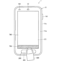
図10は、動作モードがスリープモードである場合に、ユーザの指600が検出対象面201をさわる様子の一例を示す図である。図10のように、指600が検出対象面201をさわると、圧力検出装置210が圧力を検出し、指紋センサ200が起動する。 FIG. 10 is a diagram showing an example of how the user's finger 600 touches the detection target surface 201 when the operation mode is the sleep mode. As shown in FIG. 10, when the finger 600 touches the detection target surface 201, the pressure detection device 210 detects the pressure and the fingerprint sensor 200 is activated.

ステップs3の後、ステップs4において、指紋センサ200が指紋を検出すると、ステップs5において、制御部100は、スリープモードを解除して、動作モードをロックモードに設定する。これにより、表示面121にはロック画面300(図6参照)が表示される。なお図9の例では、ステップs5は、ステップs4の後に実行されているが、ステップs4の前に実行されてもよい。 After step s3, when the fingerprint sensor 200 detects a fingerprint in step s4, in step s5, the control unit 100 cancels the sleep mode and sets the operation mode to the lock mode. As a result, the lock screen 300 (see FIG. 6) is displayed on the display surface 121. In the example of FIG. 9, step s5 is executed after step s4, but may be executed before step s4.

次にステップs6において、制御部100は、上述のようにして、ステップs4で得られる指紋検出結果に基づいて指紋認証を行う。ステップs6の後、制御部100は、ステップs7において、指紋認証が成功したか否かを判定する。ステップs7においてYesと判定されると、制御部100は、ステップs8において、ロックモードを解除して、動作モードを非ロックモードに設定する。そして、ステップs9において、制御部100は、表示部120にホーム画面400(図7,8参照)を表示させる。その後、ステップs10において、制御部100は、指紋センサ200を停止する。 Next, in step s6, the control unit 100 performs fingerprint authentication based on the fingerprint detection result obtained in step s4 as described above. After step s6, the control unit 100 determines in step s7 whether or not the fingerprint authentication was successful. If it is determined to be Yes in step s7, the control unit 100 releases the lock mode and sets the operation mode to the non-lock mode in step s8. Then, in step s9, the control unit 100 causes the display unit 120 to display the home screen 400 (see FIGS. 7 and 8). After that, in step s10, the control unit 100 stops the fingerprint sensor 200.

一方で、ステップs7においてNoと判定されると、ステップs11において、制御部100は、ユーザ認証が失敗したことを通知する失敗通知情報を、表示部120に表示させる。図11は失敗通知情報650の表示例を示す図である。図11に示されるように、失敗通知情報650はロック画面300に示される。本例では、図11に示されるように、制御部100は、失敗通知情報650だけではなく、検出対象面201を再度さわることを指示する再実行指示情報651も表示部120に表示させる。ステップs11の後、制御部100は、ステップs10を実行して指紋センサ200を停止する。 On the other hand, if No is determined in step s7, in step s11, the control unit 100 causes the display unit 120 to display the failure notification information notifying that the user authentication has failed. FIG. 11 is a diagram showing a display example of the failure notification information 650. As shown in FIG. 11, the failure notification information 650 is shown on the lock screen 300. In this example, as shown in FIG. 11, the control unit 100 causes the display unit 120 to display not only the failure notification information 650 but also the re-execution instruction information 651 instructing the detection target surface 201 to be touched again. After step s11, the control unit 100 executes step s10 to stop the fingerprint sensor 200.

このように、本例では、圧力検出装置210での圧力の検出に応じて、指紋センサ200が起動する。これにより、指紋センサ200が常に動作している場合と比較して、電子機器1の消費電力を低減することができる。 As described above, in this example, the fingerprint sensor 200 is activated in response to the pressure detection by the pressure detection device 210. As a result, the power consumption of the electronic device 1 can be reduced as compared with the case where the fingerprint sensor 200 is always in operation.

動作モードがロックモードである場合、ユーザは、検出対象面201を指でさわることによって、電子機器1にその動作モードをロックモードから非ロックモードに変更させることができる。上述のステップs11において、失敗通知情報650が表示面121に表示されるときには、動作モードはロックモードである。したがって、ステップs11の後に、ユーザは、検出対象面201を指でさわることによって、電子機器1にその動作モードをロックモードから非ロックモードに変更させることができる。 When the operation mode is the lock mode, the user can cause the electronic device 1 to change the operation mode from the lock mode to the unlock mode by touching the detection target surface 201 with a finger. In step s11 described above, when the failure notification information 650 is displayed on the display surface 121, the operation mode is the lock mode. Therefore, after step s11, the user can change the operation mode of the electronic device 1 from the locked mode to the unlocked mode by touching the detection target surface 201 with a finger.

図12は、動作モードがロックモードである場合に検出対象面201が指でさわられるときの電子機器1の動作の一例を示すフローチャートである。図12に示されるように、制御部100は、動作モードがロックモードである場合(ステップs21)、上述のステップs2と同様に、ステップs22において、圧力検出結果に基づいて、圧力検出装置210が圧力を検出したことを特定すると、ステップs23において指紋センサ200を起動する。 FIG. 12 is a flowchart showing an example of the operation of the electronic device 1 when the detection target surface 201 is touched by a finger when the operation mode is the lock mode. As shown in FIG. 12, when the operation mode is the lock mode (step s21), the control unit 100 uses the pressure detection device 210 based on the pressure detection result in step s22 as in step s2 described above. When it is specified that the pressure is detected, the fingerprint sensor 200 is activated in step s23.

ステップs23の後、ステップs24において、指紋センサ200が指紋を検出すると、ステップs25において、制御部100は、ステップs24で得られる指紋検出結果に基づいて指紋認証を行う。ステップs25の後、制御部100は、ステップs26において、指紋認証が成功したか否かを判定する。ステップs26においてYesと判定されると、制御部100は、ステップs27において、ロックモードを解除して、動作モードを非ロックモードに設定する。そして、ステップs28において、制御部100は、表示部120にホーム画面400を表示させる。その後、ステップs29において、制御部100は、指紋センサ200を停止する。 After step s23, when the fingerprint sensor 200 detects a fingerprint in step s24, in step s25, the control unit 100 performs fingerprint authentication based on the fingerprint detection result obtained in step s24. After step s25, the control unit 100 determines in step s26 whether or not the fingerprint authentication is successful. If it is determined to be Yes in step s26, the control unit 100 releases the lock mode and sets the operation mode to the non-lock mode in step s27. Then, in step s28, the control unit 100 causes the display unit 120 to display the home screen 400. After that, in step s29, the control unit 100 stops the fingerprint sensor 200.

一方で、ステップs26においてNoと判定されると、ステップs30において、制御部100は、上述のステップs11と同様に、失敗通知情報650を表示部120に表示させる。その後、制御部100は、ステップs29を実行して、指紋センサ200を停止する。 On the other hand, if No is determined in step s26, in step s30, the control unit 100 causes the display unit 120 to display the failure notification information 650 as in the above-mentioned step s11. After that, the control unit 100 executes step s29 to stop the fingerprint sensor 200.

なお、圧力検出装置210と同様に、スリープモード及び通常モードにおいて、指紋センサ200が常に動作する場合には、上記のステップs2,s3,s22,s23の実行は不要となる。 As with the pressure detection device 210, when the fingerprint sensor 200 always operates in the sleep mode and the normal mode, it is not necessary to execute the above steps s2, s3, s22, and s23.

<圧力検出結果を利用した検出対象面に対する操作の特定>
本例では、動作モードが非ロックモードである場合、制御部100は、圧力検出結果に基づいて、検出対象面201に対する操作を特定することが可能である。
<Specification of operation for the surface to be detected using the pressure detection result>
In this example, when the operation mode is the non-lock mode, the control unit 100 can specify the operation for the detection target surface 201 based on the pressure detection result.

例えば、制御部100は、圧力検出結果に基づいて、検出対象面201上を指等の操作子が移動する操作を特定することができる。また制御部100は、例えば、検出対象面201を指等の操作子が押す操作を、圧力検出結果に基づいて特定することができる。以後、操作対象面上を指等の操作子が移動する操作を単に「移動操作」と呼ぶことがある。また、操作対象面を指等の操作子が押す操作を「押し操作」と呼ぶことがある。 For example, the control unit 100 can specify an operation in which an operator such as a finger moves on the detection target surface 201 based on the pressure detection result. Further, the control unit 100 can specify, for example, an operation in which an operator such as a finger presses the detection target surface 201 based on the pressure detection result. Hereinafter, the operation in which an operator such as a finger moves on the operation target surface may be simply referred to as a “movement operation”. Further, an operation in which an operator such as a finger presses the operation target surface may be referred to as a "pushing operation".

移動操作には、例えば、フリック操作及びスワイプ操作が含まれる。押し操作には、例えば、タップ操作、ロングタップ操作及びダブルタップ操作が含まれる。ロングタップ操作は、指等の操作子が操作対象面を押してから、その押した状態をしばらく維持してその押した箇所から離れる操作である。ダブルタップ操作は、操作子が操作対象面を押してから、その押した箇所からすぐに離れる操作を連続して2回繰り返す操作である。また、押し操作には、タップ操作のように、操作子が操作対象面を押してから離れる操作ではなく、操作子が操作対象面から離れるか否かは関係なく、操作子が操作対象面を押すだけの操作も含まれる。以後、この操作を「単純な押し操作」と呼ぶことがある。 The move operation includes, for example, a flick operation and a swipe operation. The push operation includes, for example, a tap operation, a long tap operation and a double tap operation. The long tap operation is an operation in which an operator such as a finger presses the operation target surface, maintains the pressed state for a while, and then moves away from the pressed portion. The double-tap operation is an operation in which the operator presses the operation target surface and then immediately leaves the pressed portion twice in succession. Further, the push operation is not an operation in which the operator presses and then leaves the operation target surface as in the tap operation, but the operator presses the operation target surface regardless of whether or not the operator leaves the operation target surface. Only operations are included. Hereinafter, this operation may be referred to as a "simple push operation".

また、制御部100は、圧力検出結果に基づいて、検出対象面201に対する移動操作の速さ及び方向を特定することができる。また、制御部100は、圧力検出結果に基づいて、検出対象面201に対する押し操作の強さを特定することができる。 Further, the control unit 100 can specify the speed and direction of the movement operation with respect to the detection target surface 201 based on the pressure detection result. Further, the control unit 100 can specify the strength of the pushing operation with respect to the detection target surface 201 based on the pressure detection result.

上述のように、圧力検出結果は、検出対象面201での圧力がかかる位置に応じて変化する。また、検出対象面201において、圧力がかかる位置が連続的に変化する場合、その位置の変化の速さに応じて圧力検出結果が変化する。さらに、圧力検出結果は、検出対象面201にかかる圧力の大きさに応じて変化する。したがって、制御部100は、圧力検出結果に基づいて、検出対象面201に対する移動操作及び押し操作を特定することができるとともに、移動操作の速さ及び方向と、押し操作の強さを特定することができる。 As described above, the pressure detection result changes depending on the position where the pressure is applied on the detection target surface 201. Further, when the position where the pressure is applied changes continuously on the detection target surface 201, the pressure detection result changes according to the speed of the change in the position. Further, the pressure detection result changes according to the magnitude of the pressure applied to the detection target surface 201. Therefore, the control unit 100 can specify the moving operation and the pushing operation with respect to the detection target surface 201 based on the pressure detection result, and also specify the speed and direction of the moving operation and the strength of the pushing operation. Can be done.

図13〜17は、検出対象面201に対する移動操作の一例を示す図である。例えば、図13に示されるように、検出対象面201の左側部分上を指600が上側に移動する場合を考える。この場合、圧力センサ211bの検出圧力は、指600の移動に応じて徐々に小さくなる。そして、圧力センサ211bの検出圧力が小さくなる速さは、指600の移動の速さ応じて大きくなる。これに対して、圧力センサ211aの検出圧力は、指600の移動に応じて徐々に大きくなっていく。そして、圧力センサ211aの検出圧力が大きくなる速さは、指600の移動の速さ応じて大きくなる。なお、圧力センサ211c及び211dの検出圧力はあまり変化しない。 13 to 17 are diagrams showing an example of a movement operation with respect to the detection target surface 201. For example, consider a case where the finger 600 moves upward on the left side portion of the detection target surface 201 as shown in FIG. In this case, the detected pressure of the pressure sensor 211b gradually decreases as the finger 600 moves. Then, the speed at which the detected pressure of the pressure sensor 211b decreases increases with the speed of movement of the finger 600. On the other hand, the detected pressure of the pressure sensor 211a gradually increases as the finger 600 moves. Then, the speed at which the detected pressure of the pressure sensor 211a increases increases with the speed of movement of the finger 600. The detected pressures of the pressure sensors 211c and 211d do not change much.

次に、図14に示されるように、検出対象面201の左右方向の中央部分上を指600が上側に移動する場合を考える。この場合、指600の移動に応じて、圧力センサ211b及び211dの検出圧力が徐々に小さくなるとともに、圧力センサ211a及び211cの検出圧力が徐々に大きくなる。そして、圧力センサ211b及び211dの検出圧力が小さくなる速さと、圧力センサ211a及び211cの検出圧力が大きくなる速さとが、指600の移動の速さ応じて大きくなる。 Next, as shown in FIG. 14, consider a case where the finger 600 moves upward on the central portion in the left-right direction of the detection target surface 201. In this case, as the finger 600 moves, the detected pressures of the pressure sensors 211b and 211d gradually decrease, and the detected pressures of the pressure sensors 211a and 211c gradually increase. Then, the speed at which the detected pressures of the pressure sensors 211b and 211d decrease and the speed at which the detected pressures of the pressure sensors 211a and 211c increase increase with the speed of movement of the finger 600.

次に、図15に示されるように、検出対象面201の右側部分上を指600が下側に移動する場合を考える。この場合、指600の移動に応じて、圧力センサ211cの検出圧力が徐々に小さくなるとともに、圧力センサ211dの検出圧力が徐々に大きくなる。そして、圧力センサ211cの検出圧力が小さくなる速さと、圧力センサ211dの検出圧力が大きくなる速さとが、指600の移動の速さ応じて大きくなる。なお、圧力センサ211a及び211bの検出圧力はあまり変化しない。 Next, consider a case where the finger 600 moves downward on the right side portion of the detection target surface 201 as shown in FIG. In this case, as the finger 600 moves, the detected pressure of the pressure sensor 211c gradually decreases, and the detected pressure of the pressure sensor 211d gradually increases. Then, the speed at which the detected pressure of the pressure sensor 211c decreases and the speed at which the detected pressure of the pressure sensor 211d increases increase according to the speed of movement of the finger 600. The detected pressures of the pressure sensors 211a and 211b do not change much.

次に、図16に示されるように、指600が検出対象面201の上下方向の中央部分上を左側から右側へ移動する場合を考える。この場合、指600の移動に応じて、圧力センサ211a及び211bの検出圧力が徐々に小さくなるとともに、圧力センサ211c及び211dの検出圧力が徐々に大きくなる。そして、圧力センサ211a及び211bの検出圧力が小さくなる速さと、圧力センサ211c及び211dの検出圧力が大きくなる速さとが、指600の移動の速さ応じて大きくなる。 Next, as shown in FIG. 16, consider a case where the finger 600 moves from the left side to the right side on the central portion in the vertical direction of the detection target surface 201. In this case, as the finger 600 moves, the detected pressures of the pressure sensors 211a and 211b gradually decrease, and the detected pressures of the pressure sensors 211c and 211d gradually increase. Then, the speed at which the detected pressures of the pressure sensors 211a and 211b decrease and the speed at which the detected pressures of the pressure sensors 211c and 211d increase increase with the speed of movement of the finger 600.

次に、図17に示されるように、指600が検出対象面201の上下方向の中央部分上を右側から左側へ移動する場合を考える。この場合、指600の移動に応じて、圧力センサ211c及び211dの検出圧力が徐々に小さくなるとともに、圧力センサ211a及び211bの検出圧力が徐々に大きくなる。そして、圧力センサ211c及び211dの検出圧力が小さくなる速さと、圧力センサ211a及び211bの検出圧力が大きくなる速さとが、指600の移動の速さ応じて大きくなる。 Next, as shown in FIG. 17, consider a case where the finger 600 moves from the right side to the left side on the central portion in the vertical direction of the detection target surface 201. In this case, as the finger 600 moves, the detected pressures of the pressure sensors 211c and 211d gradually decrease, and the detected pressures of the pressure sensors 211a and 211b gradually increase. Then, the speed at which the detected pressures of the pressure sensors 211c and 211d decrease and the speed at which the detected pressures of the pressure sensors 211a and 211b increase increase with the speed of movement of the finger 600.

このように、圧力検出結果は、検出対象面201に対する移動操作に応じて変化することから、制御部100は、圧力検出結果に基づいて、検出対象面201に対する移動操作を特定することができる。また、圧力検出結果は、検出対象面201に対する移動操作の速さ及び方向に応じて変化することから、制御部100は、圧力検出結果に基づいて、検出対象面201に対する移動操作の速さ及び方向を特定することができる。 As described above, since the pressure detection result changes according to the movement operation with respect to the detection target surface 201, the control unit 100 can specify the movement operation with respect to the detection target surface 201 based on the pressure detection result. Further, since the pressure detection result changes according to the speed and direction of the movement operation with respect to the detection target surface 201, the control unit 100 has the speed of the movement operation with respect to the detection target surface 201 and the speed of the movement operation with respect to the detection target surface 201 based on the pressure detection result. The direction can be specified.

また、圧力検出結果は、検出対象面201にかかる圧力の大きさに応じて変化することから、制御部100は、圧力検出結果に基づいて、検出対象面201に対する押し操作を特定することができるとともに、当該押し操作の強さを特定することができる。制御部100は、圧力検出結果に基づいて、検出対象面201が押される強さを特定することができると言える。 Further, since the pressure detection result changes according to the magnitude of the pressure applied to the detection target surface 201, the control unit 100 can specify the pushing operation on the detection target surface 201 based on the pressure detection result. At the same time, the strength of the pushing operation can be specified. It can be said that the control unit 100 can specify the strength with which the detection target surface 201 is pressed based on the pressure detection result.

なお、上記の説明から理解できるように、制御部100が圧力検出結果に基づいて特定することが可能な検出対象面201に対する操作は、圧力検出装置210が備える複数の圧力センサ211の数と当該複数の圧力センサ211の配置位置とに応じて変化する。 As can be understood from the above description, the operation for the detection target surface 201 that can be specified by the control unit 100 based on the pressure detection result is the number of the plurality of pressure sensors 211 included in the pressure detection device 210 and the corresponding operation. It changes according to the arrangement position of the plurality of pressure sensors 211.

<検出対象面に対する操作に応じた処理の一例>
動作モードが非ロックモードである場合、制御部100は、タッチパネル130が検出する表示面121に対する操作に応じて様々な処理を行うことが可能であるのと同様に、特定した検出対象面201に対する操作に応じて様々な処理を行うことが可能である。
<Example of processing according to the operation on the surface to be detected>
When the operation mode is the non-lock mode, the control unit 100 can perform various processes depending on the operation on the display surface 121 detected by the touch panel 130, and similarly, the specified detection target surface 201 can be processed. It is possible to perform various processes according to the operation.

例えば、制御部100は、特定した、検出対象面201に対する操作に応じて、表示部120(言い換えれば表示面121)の表示を制御することが可能である。制御部100は、例えば、検出対象面201に対するスワイプ操作及びフリック操作に応じて、表示部120の表示をスクロールすることができる。例えば、制御部100は、検出対象面201に対するスワイプ操作を特定すると、そのスワイプ操作の方向(例えば下方向)に表示部120の表示をスクロールする。このとき、制御部100は、スワイプ操作の速さが大きいほど、表示部120の表示をスクロールする速さを大きくしてもよい。また、制御部100は、検出対象面201に対するフリック操作に応じて、表示部120の表示をスクロールする場合、フリック操作の速さが大きいほど、表示部120の表示のスクロール量を大きくしてもよい。 For example, the control unit 100 can control the display of the display unit 120 (in other words, the display surface 121) in response to the specified operation on the detection target surface 201. The control unit 100 can scroll the display of the display unit 120 in response to a swipe operation and a flick operation on the detection target surface 201, for example. For example, when the control unit 100 specifies a swipe operation for the detection target surface 201, the control unit 100 scrolls the display of the display unit 120 in the direction of the swipe operation (for example, downward direction). At this time, the control unit 100 may increase the speed of scrolling the display of the display unit 120 as the speed of the swipe operation increases. Further, when the control unit 100 scrolls the display of the display unit 120 in response to the flick operation on the detection target surface 201, the faster the flick operation speed, the larger the scroll amount of the display of the display unit 120 may be. good.

また、制御部100は、検出対象面201に対するスワイプ操作及びフリック操作に応じて、表示面121に表示されているページを別のページに切り替えてもよい。例えば、表示面121にホーム画面400が表示されている場合を考える。この場合、制御部100は、検出対象面201に対する右方向のフリック操作を検出すると、現在表示されているページ(例えば図7に示されるページ)の右隣のページ(例えば図8に示されるページ)を表示面121に表示する。 Further, the control unit 100 may switch the page displayed on the display surface 121 to another page in response to a swipe operation and a flick operation on the detection target surface 201. For example, consider the case where the home screen 400 is displayed on the display surface 121. In this case, when the control unit 100 detects a flick operation in the right direction with respect to the detection target surface 201, the page to the right of the currently displayed page (for example, the page shown in FIG. 7) (for example, the page shown in FIG. 8) ) Is displayed on the display surface 121.

また、制御部100は、検出対象面201に対する下方向のスワイプ操作及びフリック操作に応じて、電子機器1に発生したイベントに関する情報を通知するための通知画面700を表示部120に表示させてもよい。この場合、制御部100は、圧力検出結果に基づいて、検出対象面201に対する下方向のスワイプ操作あるいはフリック操作を特定すると、通知画面700を表示部120に表示させる。図18は通知画面700の一例を示す図である。 Further, the control unit 100 may display the notification screen 700 for notifying the information regarding the event generated in the electronic device 1 on the display unit 120 in response to the downward swipe operation and the flick operation with respect to the detection target surface 201. good. In this case, when the control unit 100 specifies a downward swipe operation or a flick operation with respect to the detection target surface 201 based on the pressure detection result, the notification screen 700 is displayed on the display unit 120. FIG. 18 is a diagram showing an example of the notification screen 700.

図18の例では、表示面121が表示する表示画面には、上述の通知領域500及び操作ボタン401〜403と、通知画面700とが含まれる。通知画面700には、電子機器1に発生したイベントに関する情報710が含まれる。図18の例では、通知画面700には、情報710として、不在着信の発生を通知する情報710aと、新しい電子メールの受信の発生を通知する情報710bとが含まれている。情報710aには、不在着信の発生を通知するアイコン710aa及び文字列710abが含まれる。情報710bには、新しい電子メールの受信の発生を通知するアイコン710ba及び文字列710bbが含まれる。 In the example of FIG. 18, the display screen displayed by the display surface 121 includes the above-mentioned notification area 500, the operation buttons 401 to 403, and the notification screen 700. The notification screen 700 includes information 710 regarding an event that has occurred in the electronic device 1. In the example of FIG. 18, the notification screen 700 includes information 710a for notifying the occurrence of a missed call and information 710b for notifying the occurrence of a new e-mail as information 710. The information 710a includes an icon 710aa for notifying the occurrence of a missed call and a character string 710ab. The information 710b includes an icon 710ba and a character string 710bb notifying that a new e-mail has been received.

表示面121に通知画面700が表示されている場合に、制御部100は、検出対象面201に対する上方向のスワイプ操作あるいはフリック操作を特定すると、表示部120に、通知画面700を表示面121から消去させる。 When the notification screen 700 is displayed on the display surface 121 and the control unit 100 specifies an upward swipe operation or flick operation with respect to the detection target surface 201, the notification screen 700 is displayed on the display unit 120 from the display surface 121. Erase.

なお制御部100は、タッチパネル130が、図19に示されるように、表示面121に対する、通知領域500からの下方向のスワイプ操作あるいはフリック操作を検出すると、図18のように、表示部120に通知画面700を表示させてもよい。 When the touch panel 130 detects a downward swipe operation or a flick operation from the notification area 500 with respect to the display surface 121 as shown in FIG. 19, the control unit 100 displays the display unit 120 as shown in FIG. The notification screen 700 may be displayed.

また制御部100は、タッチパネル130が、表示面121に表示される通知画面700に対する上方向のスワイプ操作あるいはフリック操作を検出すると、表示部120に、通知画面700を表示面121から消去させてもよい。 Further, when the touch panel 130 detects an upward swipe operation or a flick operation on the notification screen 700 displayed on the display surface 121, the control unit 100 may cause the display unit 120 to erase the notification screen 700 from the display surface 121. good.

また制御部100は、特定した、検出対象面201に対する操作に応じたアプリケーションを実行してもよい。この場合、検出対象面201に対する操作と、その操作が行われたときに実行されるアプリケーションとが対応付けられる。検出対象面201に対する操作とアプリケーションとの対応関係は記憶部103に記憶される。 Further, the control unit 100 may execute an application corresponding to the specified operation on the detection target surface 201. In this case, the operation on the detection target surface 201 is associated with the application executed when the operation is performed. The correspondence between the operation on the detection target surface 201 and the application is stored in the storage unit 103.

例えば、検出対象面201の左上部分201a、左下部分201b、右上部分201c及び右下部分201d(図4参照)に対する、強さが大きい単純な押し操作に対して、記憶部103内の第1乃至第4アプリケーションがそれぞれ対応付けられている場合を考える。この場合、制御部100は、検出対象面201の左上部分201aに対する、強さが大きい単純な押し操作を特定すると、記憶部103内の第1アプリケーション(例えばカメラアプリケーション)を実行する。制御部100は、圧力センサ211aの検出圧力が第1基準圧力以上のとき、検出対象面201の左上部分201aに対して、強さが大きい単純な押し操作が行われたと判定する。制御部100は、検出対象面201の左下部分201bに対する、強さが大きい単純な押し操作を特定すると、記憶部103内の第2アプリケーション(例えば通話アプリケーション)を実行する。制御部100は、検出対象面201の右上部分201cに対する、強さが大きい単純な押し操作を特定すると、記憶部103内の第3アプリケーション(例えば音楽再生制御アプリケーション)を実行する。そして、制御部100は、検出対象面201の右下部分201dに対する、強さが大きい単純な押し操作を特定すると、記憶部103内の第4アプリケーション(例えばブラウザ)を実行する。 For example, for a simple pressing operation with high strength with respect to the upper left portion 201a, the lower left portion 201b, the upper right portion 201c, and the lower right portion 201d (see FIG. 4) of the detection target surface 201, the first to the first in the storage unit 103. Consider the case where the fourth application is associated with each other. In this case, the control unit 100 executes a first application (for example, a camera application) in the storage unit 103 when a simple pressing operation having a high strength is specified with respect to the upper left portion 201a of the detection target surface 201. When the detection pressure of the pressure sensor 211a is equal to or higher than the first reference pressure, the control unit 100 determines that a simple pushing operation having a high strength has been performed on the upper left portion 201a of the detection target surface 201. When the control unit 100 specifies a simple pressing operation having a high strength with respect to the lower left portion 201b of the detection target surface 201, the control unit 100 executes a second application (for example, a call application) in the storage unit 103. When the control unit 100 specifies a simple pressing operation having a high strength with respect to the upper right portion 201c of the detection target surface 201, the control unit 100 executes a third application (for example, a music reproduction control application) in the storage unit 103. Then, when the control unit 100 specifies a simple pressing operation having a high strength with respect to the lower right portion 201d of the detection target surface 201, the control unit 100 executes a fourth application (for example, a browser) in the storage unit 103.

他の例として、検出対象面201に対する右方向及び左方向のフリック操作に対して、記憶部103内の第1及び第2アプリケーションがそれぞれ対応付けられている場合を考える。この場合、制御部100は、検出対象面201に対する左方向のフリック操作を特定すると、そのフリック操作の速さにかかわらず、記憶部103内の第1アプリケーションを実行する。そして、制御部100は、検出対象面201に対する右方向のフリック操作を特定すると、そのフリック操作の速さにかかわらず、記憶部103内の第2アプリケーションを実行する。 As another example, consider a case where the first and second applications in the storage unit 103 are associated with the flick operation in the right direction and the left direction with respect to the detection target surface 201, respectively. In this case, when the control unit 100 specifies a flick operation in the left direction with respect to the detection target surface 201, the control unit 100 executes the first application in the storage unit 103 regardless of the speed of the flick operation. Then, when the control unit 100 specifies a flick operation in the right direction with respect to the detection target surface 201, the control unit 100 executes the second application in the storage unit 103 regardless of the speed of the flick operation.

他の例として、検出対象面201に対する、速さが大きいフリック操作及び速さが小さいフリック操作に対して、記憶部103内の第1及び第2アプリケーションがそれぞれ対応付けられている場合を考える。この場合、制御部100は、検出対象面201に対する、速さが大きいフリック操作を特定すると、そのフリック操作の方向にかかわらず、記憶部103内の第1アプリケーションを実行する。そして、制御部100は、検出対象面201に対する、速さが小さいフリック操作を特定すると、そのフリック操作の方向にかかわらず、記憶部103内の第2アプリケーションを実行する。 As another example, consider a case where the first and second applications in the storage unit 103 are associated with a flick operation having a high speed and a flick operation having a low speed with respect to the detection target surface 201, respectively. In this case, when the control unit 100 specifies a flick operation having a high speed with respect to the detection target surface 201, the control unit 100 executes the first application in the storage unit 103 regardless of the direction of the flick operation. Then, when the control unit 100 specifies a flick operation having a low speed with respect to the detection target surface 201, the control unit 100 executes the second application in the storage unit 103 regardless of the direction of the flick operation.

なお、記憶部103に記憶される、検出対象面201に対する操作とアプリケーションの対応関係は、ユーザによって設定可能であってもよい。 The correspondence between the operation and the application stored in the storage unit 103 with respect to the detection target surface 201 may be set by the user.

また上記の例では、制御部100は、検出対象面201に対する操作の速さ、方向及び強さのすべてを特定しているが、検出対象面201に対する操作の速さ、方向及び強さの少なくとも一つを特定してもよい。 Further, in the above example, the control unit 100 specifies all of the speed, direction, and strength of the operation with respect to the detection target surface 201, but at least the speed, direction, and strength of the operation with respect to the detection target surface 201. You may specify one.

以上のように、本例に係る電子機器1は、指紋センサ200の検出対象面201にかかる圧力を検出することが可能な複数の圧力センサ211を有する圧力検出装置210を備えている。そして、圧力検出装置210での圧力検出結果は、検出対象面201での圧力がかかる位置に応じて変化する。電子機器1は、このような圧力検出結果を利用した処理が可能となることから、電子機器1の利便性が向上する。 As described above, the electronic device 1 according to this example includes a pressure detection device 210 having a plurality of pressure sensors 211 capable of detecting the pressure applied to the detection target surface 201 of the fingerprint sensor 200. Then, the pressure detection result by the pressure detection device 210 changes according to the position where the pressure is applied on the detection target surface 201. Since the electronic device 1 can perform processing using such a pressure detection result, the convenience of the electronic device 1 is improved.

また、圧力センサの厚さは、押しボタン等のハードウェアボタンの厚さよりも小さくすることが可能である。したがって、本例のように、電子機器1が、検出対象面201にかかる圧力を検出する圧力センサ211を備えることによって、検出対象面201が押されるとオン状態となる押しボタン等のハードウェアボタンを備える場合よりも、電子機器の1の厚みを小さくすることが可能となる。 Further, the thickness of the pressure sensor can be made smaller than the thickness of a hardware button such as a push button. Therefore, as in this example, the electronic device 1 is provided with a pressure sensor 211 that detects the pressure applied to the detection target surface 201, so that a hardware button such as a push button that is turned on when the detection target surface 201 is pressed is provided. It is possible to reduce the thickness of 1 of the electronic device as compared with the case of providing.

また上記のように、制御部100が、圧力検出結果に基づいて、検出対象面201に対する操作を特定し、特定した操作に応じた処理を行う場合には、ユーザは、検出対象面201を操作することによって、その操作に応じた処理を電子機器1に実行させることができる。よって、電子機器1の利便性が向上する。本例のように、検出対象面201が、例えば電子機器1の前面の下端部に位置する場合には、電子機器1を片手で持つユーザは、電子機器1を持つその手で検出対象面201を操作することが容易となる。よって、電子機器1の利便性がさらに向上する。 Further, as described above, when the control unit 100 identifies an operation on the detection target surface 201 based on the pressure detection result and performs a process according to the specified operation, the user operates the detection target surface 201. By doing so, the electronic device 1 can be made to execute the process corresponding to the operation. Therefore, the convenience of the electronic device 1 is improved. As in this example, when the detection target surface 201 is located at the lower end of the front surface of the electronic device 1, for example, a user holding the electronic device 1 with one hand can use the electronic device 1 with his / her hand to detect the detection target surface 201. It becomes easy to operate. Therefore, the convenience of the electronic device 1 is further improved.

また、制御部100が、圧力検出結果に基づいて、検出対象面201に対する操作の速さを特定する場合には、ユーザは、検出対象面201に対する操作の速さに応じた処理を、電子機器1に実行させることができる。また、制御部100が、圧力検出結果に基づいて、検出対象面201に対する操作の方向を特定する場合には、ユーザは、検出対象面201に対する操作の方向に応じた処理を、電子機器1に実行させることができる。また、制御部100が、圧力検出結果に基づいて、検出対象面201に対する操作の強さを特定する場合には、ユーザは、検出対象面に対する操作の強さに応じた処理を、電子機器1に実行させることができる。よって、電子機器1の利便性が向上する。 Further, when the control unit 100 specifies the operation speed with respect to the detection target surface 201 based on the pressure detection result, the user performs a process according to the operation speed with respect to the detection target surface 201 as an electronic device. Can be executed by 1. Further, when the control unit 100 specifies the direction of operation with respect to the detection target surface 201 based on the pressure detection result, the user performs processing according to the direction of operation with respect to the detection target surface 201 to the electronic device 1. Can be executed. Further, when the control unit 100 specifies the strength of the operation on the detection target surface 201 based on the pressure detection result, the user performs the processing according to the strength of the operation on the detection target surface 1 in the electronic device 1. Can be executed. Therefore, the convenience of the electronic device 1 is improved.

また、制御部100が、特定した検出対象面201に対する操作に応じて表示部120の表示を制御する場合には、ユーザは、検出対象面201に対して操作を行うことによって、その操作に応じた表示部120の表示の制御を電子機器1に実行させることができる。よって、電子機器1の利便性が向上する。 Further, when the control unit 100 controls the display of the display unit 120 in response to the operation on the specified detection target surface 201, the user responds to the operation by performing the operation on the detection target surface 201. It is possible to cause the electronic device 1 to control the display of the display unit 120. Therefore, the convenience of the electronic device 1 is improved.

また、制御部100は、特定した検出対象面201に対する操作に応じたアプリケーションを実行する場合には、ユーザは、検出対象面201に対して操作を行うことによって、その操作に応じたアプリケーションを電子機器1に実行させることができる。よって、電子機器1の利便性が向上する。 Further, when the control unit 100 executes an application corresponding to an operation on the specified detection target surface 201, the user performs an operation on the detection target surface 201 to electronically execute the application corresponding to the operation. It can be executed by the device 1. Therefore, the convenience of the electronic device 1 is improved.

<電子機器の動作の他の例>
以下に電子機器1の動作の他の例について説明する。
<Other examples of the operation of electronic devices>
Other examples of the operation of the electronic device 1 will be described below.

<第1の他の例>
ユーザが検出対象面201を指等でさわるとき、表示面121を誤ってさわってしまう可能性がある。その結果、タッチパネル130が表示面121に対する誤った操作入力を検出し、それに応じて、制御部100が、ユーザが意図しない処理を実行する可能性がある。特に、本例のように、検出対象面201が表示面121と同じ面(本例では機器ケース11の前面11a)に位置する場合には、ユーザが検出対象面201を指等でさわるときに、タッチパネル130が表示面121に対する誤った操作入力を検出する可能性が高くなる。例えば、表示面121のうち、検出対象面201に近い場所に表示される操作ボタン401〜403のいずれか一つに対する誤った操作をタッチパネル130が検出する可能性がある。
<First other example>
When the user touches the detection target surface 201 with a finger or the like, the display surface 121 may be erroneously touched. As a result, the touch panel 130 may detect an erroneous operation input to the display surface 121, and the control unit 100 may execute a process unintended by the user accordingly. In particular, when the detection target surface 201 is located on the same surface as the display surface 121 (in this example, the front surface 11a of the device case 11) as in this example, when the user touches the detection target surface 201 with a finger or the like. , The touch panel 130 is more likely to detect an erroneous operation input to the display surface 121. For example, the touch panel 130 may detect an erroneous operation on any one of the operation buttons 401 to 403 displayed on the display surface 121 near the detection target surface 201.

そこで、本例では、制御部100は、圧力検出装置210での圧力の検出中に、表示面121の少なくとも一部に対する操作入力を無効にする。例えば、制御部100は、複数の圧力センサ211の少なくとも一つが圧力を検出しているときには、表示面121の少なくとも一部に対する操作入力を無効にする。これにより、ユーザが意図しない処理が電子機器1で実行される可能性を低減することができる。 Therefore, in this example, the control unit 100 invalidates the operation input to at least a part of the display surface 121 during the pressure detection by the pressure detection device 210. For example, the control unit 100 invalidates the operation input to at least a part of the display surface 121 when at least one of the plurality of pressure sensors 211 detects the pressure. As a result, it is possible to reduce the possibility that the processing not intended by the user is executed by the electronic device 1.

制御部100は、表示面121の全領域に対する操作入力を無効にしてもよいし、表示面121の一部に対する操作入力を無効にしてもよい。制御部100は、タッチパネル130の動作を停止することによって、表示面121の全領域に対する操作入力を無効にしてもよいし、タッチパネル130の出力をすべて無視することによって、表示面121の全領域に対する操作入力を無効にしてもよい。また、制御部100は、タッチパネル130の一部の動作を停止することによって、表示面121の一部に対する操作入力を無効にしてもよい。また、制御部100は、タッチパネル130の出力の一部を無視することによって、表示面121の一部に対する操作入力を無効にしてもよい。 The control unit 100 may invalidate the operation input for the entire area of the display surface 121, or may invalidate the operation input for a part of the display surface 121. The control unit 100 may invalidate the operation input for the entire area of the display surface 121 by stopping the operation of the touch panel 130, or may disable the operation input for the entire area of the display surface 121, or ignore all the outputs of the touch panel 130 for the entire area of the display surface 121. The operation input may be invalidated. Further, the control unit 100 may invalidate the operation input for a part of the display surface 121 by stopping the operation of a part of the touch panel 130. Further, the control unit 100 may invalidate the operation input for a part of the display surface 121 by ignoring a part of the output of the touch panel 130.

制御部100が、表示面121の一部に対する操作入力を無効にする場合には、表示面121は、それに対する操作入力が無効にされる対象部分と、それに対する操作入力が無効にされない非対象部分とを有することになる。この場合、対象部分は、非対象部分よりも検出対象面201に近い場所に位置してもよい。図20は、対象部分750及び非対象部分760の一例を示す図である。図20の例では、表示面121において、検出対象面201に近い下端部が対象部分750となっており、それ以外が非対象部分760となっている。表示面121のうち、例えば、操作ボタン401〜403が表示される部分が、対象部分750に設定される。 When the control unit 100 invalidates the operation input for a part of the display surface 121, the display surface 121 has a target portion in which the operation input for the target portion is invalidated and a non-target portion in which the operation input for the target portion is not invalidated. Will have a portion. In this case, the target portion may be located closer to the detection target surface 201 than the non-target portion. FIG. 20 is a diagram showing an example of a target portion 750 and a non-target portion 760. In the example of FIG. 20, in the display surface 121, the lower end portion near the detection target surface 201 is the target portion 750, and the other portion is the non-target portion 760. Of the display surface 121, for example, the portion where the operation buttons 401 to 403 are displayed is set to the target portion 750.

なお、制御部100は、指紋認証中、かつ圧力検出装置210での圧力の検出中に、表示面121の少なくとも一部に対する操作入力を無効にしてもよい。例えば、制御部100は、指紋認証の実行中であって(例えば上述のステップs6あるいはステップs25の実行中)、複数の圧力センサ211の少なくとも一つが圧力を検出しているときには、表示面121の少なくとも一部に対する操作入力を無効にしてもよい。これにより、ユーザが検出対象面201をさわって電子機器1に指紋認証を実行させる場合、ユーザが意図しない処理が電子機器1で実行される可能性を低減することができる。 The control unit 100 may invalidate the operation input to at least a part of the display surface 121 during fingerprint authentication and pressure detection by the pressure detection device 210. For example, when the control unit 100 is executing fingerprint authentication (for example, during the execution of step s6 or step s25 described above) and at least one of the plurality of pressure sensors 211 is detecting pressure, the control unit 100 of the display surface 121. The operation input for at least a part may be invalidated. As a result, when the user touches the detection target surface 201 to cause the electronic device 1 to perform fingerprint authentication, it is possible to reduce the possibility that the processing not intended by the user is executed on the electronic device 1.

<第2の他の例>
ユーザが指で検出対象面201をさわって、電子機器1に指紋認証を実行させる場合、検出対象面201での指の位置が適切でない場合には、制御部100は適切に指紋認証を行えない可能性がある。例えば、検出対象面201での指の位置が、検出対象面201の左端あるいは右端である場合には、制御部100は適切に指紋認証を行えない可能性がある。
<Second other example>
When the user touches the detection target surface 201 with a finger to cause the electronic device 1 to perform fingerprint authentication, if the position of the finger on the detection target surface 201 is not appropriate, the control unit 100 cannot properly perform fingerprint authentication. there is a possibility. For example, if the position of the finger on the detection target surface 201 is the left end or the right end of the detection target surface 201, the control unit 100 may not be able to properly perform fingerprint authentication.

そこで、本例では、制御部100は、指紋認証を行う場合に、検出対象面201での指の位置についての基準位置からのずれを、圧力検出結果に基づいて特定する。そして、制御部100は、ユーザに対して通知を行う通知部に、特定したずれを通知させる。ユーザに対して通知を行う通知部には、表示部120及びスピーカ160が含まれる。また、電子機器1が、機器ケース11を振動させて、当該機器ケース11をさわるユーザに対して振動を伝えることが可能なバイブレータを備える場合には、当該バイブレータが通知部に含まれる。また、電子機器1が、機器ケース11の外部に光を発光する発光部(例えばLEDなど)を備える場合には、当該発光部が通知部に含まれる。 Therefore, in this example, when performing fingerprint authentication, the control unit 100 specifies the deviation of the finger position on the detection target surface 201 from the reference position based on the pressure detection result. Then, the control unit 100 causes the notification unit that notifies the user to notify the specified deviation. The notification unit that notifies the user includes a display unit 120 and a speaker 160. Further, when the electronic device 1 includes a vibrator capable of vibrating the device case 11 and transmitting the vibration to the user who touches the device case 11, the vibrator is included in the notification unit. When the electronic device 1 includes a light emitting unit (for example, an LED) that emits light outside the device case 11, the light emitting unit is included in the notification unit.

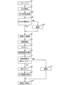
図21は本例に係る電子機器1の動作の一例を示すフローチャートである。図21に示されるフローチャートは、上述の図9に示されるフローチャートにおいて、ステップs11の替わりにステップs51,s52が実行されるものである。 FIG. 21 is a flowchart showing an example of the operation of the electronic device 1 according to this example. In the flowchart shown in FIG. 21, in the flowchart shown in FIG. 9 described above, steps s51 and s52 are executed instead of step s11.

図21に示されるように、ステップs7において指紋認証が失敗したと判定されると、ステップs51において、制御部100は、ステップs2で得られる圧力検出結果に基づいて、検出対象面201での指の位置についての基準位置からのずれを特定する。基準位置としては、例えば、検出対象面201の中心201e(図4参照)が採用される。 As shown in FIG. 21, when it is determined in step s7 that the fingerprint authentication has failed, in step s51, the control unit 100 uses a finger on the detection target surface 201 based on the pressure detection result obtained in step s2. Identify the deviation from the reference position for the position of. As the reference position, for example, the center 201e (see FIG. 4) of the detection target surface 201 is adopted.

ステップs51において、制御部100は、例えば、圧力センサ211aの検出圧力が、圧力センサ211cの検出圧力よりも大きい場合、検出対象面201での指の位置が基準位置よりも左にずれていると判定する。また、制御部100は、圧力センサ211bの検出圧力が、圧力センサ211dの検出圧力よりも大きい場合、検出対象面201での指の位置が基準位置よりも左にずれていると判定する。一方で、制御部100は、圧力センサ211cの検出圧力が、圧力センサ211aの検出圧力よりも大きい場合、検出対象面201での指の位置が基準位置よりも右にずれていると判定する。また、制御部100は、圧力センサ211dの検出圧力が、圧力センサ211bの検出圧力よりも大きい場合、検出対象面201での指の位置が基準位置よりも右にずれていると判定する。以後、検出対象面201での指の位置についての基準位置からのずれを単に「位置ずれ」と呼ぶことがある。 In step s51, for example, when the detected pressure of the pressure sensor 211a is larger than the detected pressure of the pressure sensor 211c, the control unit 100 determines that the position of the finger on the detection target surface 201 is shifted to the left from the reference position. judge. Further, when the detected pressure of the pressure sensor 211b is larger than the detected pressure of the pressure sensor 211d, the control unit 100 determines that the position of the finger on the detection target surface 201 is shifted to the left from the reference position. On the other hand, when the detected pressure of the pressure sensor 211c is larger than the detected pressure of the pressure sensor 211a, the control unit 100 determines that the position of the finger on the detection target surface 201 is shifted to the right from the reference position. Further, when the detected pressure of the pressure sensor 211d is larger than the detected pressure of the pressure sensor 211b, the control unit 100 determines that the position of the finger on the detection target surface 201 is shifted to the right from the reference position. Hereinafter, the deviation of the finger position on the detection target surface 201 from the reference position may be simply referred to as “positional deviation”.

ステップs51の後、ステップs52において、制御部100は、位置ずれを通知部に通知させる。制御部100は、例えば、位置ずれを通知する位置ずれ通知情報652を表示部120に表示させる。ステップs53の後、ステップs10が実行される。 After step s51, in step s52, the control unit 100 causes the notification unit to notify the misalignment. For example, the control unit 100 causes the display unit 120 to display the position shift notification information 652 for notifying the position shift. After step s53, step s10 is executed.

図22は位置ずれ通知情報652の一例を示す図である。図22に示されるように、本例では、制御部100は、位置ずれ通知情報652だけではなく、失敗通知情報650及び再実行指示情報651も表示部120に表示させる。なお、検出対象面201での指の位置が基準位置からずれていない場合には、位置ずれがユーザに通知されずに、例えば上述の図11のように失敗通知情報650及び再実行指示情報651が表示面121に表示されてもよい。この場合、表示面121には、位置ずれが無いことを示す情報が表示されてもよい。 FIG. 22 is a diagram showing an example of the position shift notification information 652. As shown in FIG. 22, in this example, the control unit 100 causes the display unit 120 to display not only the misalignment notification information 652 but also the failure notification information 650 and the re-execution instruction information 651. If the position of the finger on the detection target surface 201 does not deviate from the reference position, the misalignment is not notified to the user, and the failure notification information 650 and the re-execution instruction information 651 are not notified to the user, for example, as shown in FIG. 11 above. May be displayed on the display surface 121. In this case, information indicating that there is no misalignment may be displayed on the display surface 121.

ステップs51については、ステップs2の後であって、ステップs7の前に実行されてもよい。また、上述の図12に示されるフローチャートにおいて、ステップs30の替わりにステップs51及びs52が実行されてもよい。この場合、ステップs51は、ステップs22の後であって、ステップs26の前に実行されてもよい。 Step s51 may be performed after step s2 and before step s7. Further, in the flowchart shown in FIG. 12 above, steps s51 and s52 may be executed instead of step s30. In this case, step s51 may be performed after step s22 and before step s26.

位置ずれを通知する通知部は表示部120に限られない。例えば、スピーカ160が位置ずれを通知してもよい。この場合、スピーカ160は、例えば、「指の位置がずれています。」という音声を出力してもよい。また、電子機器1が、機器ケース11を振動させるバイブレータを備える場合には、当該バイブレータが位置ずれを通知してもよい。この場合、バイブレータは、特定の振動パターンで機器ケース11を振動させることによって、ユーザに位置ずれを通知してもよい。また、電子機器1がLED等の発光部を備える場合には、当該発光部が位置ずれを通知してもよい。この場合、発光部は、特定の発光パターンで発光することによって、ユーザに位置ずれを通知してもよい。また、表示部120、スピーカ160、バイブレータ及び発光部の少なくとも二つが位置ずれを通知してもよい。 The notification unit for notifying the misalignment is not limited to the display unit 120. For example, the speaker 160 may notify the misalignment. In this case, the speaker 160 may output, for example, the voice "The position of the finger is misaligned." Further, when the electronic device 1 includes a vibrator that vibrates the device case 11, the vibrator may notify the position shift. In this case, the vibrator may notify the user of the misalignment by vibrating the device case 11 with a specific vibration pattern. Further, when the electronic device 1 includes a light emitting unit such as an LED, the light emitting unit may notify the position shift. In this case, the light emitting unit may notify the user of the misalignment by emitting light in a specific light emitting pattern. Further, at least two of the display unit 120, the speaker 160, the vibrator and the light emitting unit may notify the position shift.

通知部は、位置ずれを通知する場合には、検出対象面201での指の位置の変更を案内する案内情報653を通知してもよい。図23,24は、表示部120が通知する案内情報653、言い換えれば、表示部120が表示する案内情報653の一例を示す図である。図23には、検出対象面201での指の位置が基準位置から左側にずれている場合の案内情報653が示されている。図24には、検出対象面201での指の位置が基準位置から右側にずれている場合の案内情報653が示されている。 When notifying the position shift, the notification unit may notify the guidance information 653 for guiding the change of the finger position on the detection target surface 201. 23 and 24 are diagrams showing an example of the guidance information 653 notified by the display unit 120, in other words, the guidance information 653 displayed by the display unit 120. FIG. 23 shows guidance information 653 when the position of the finger on the detection target surface 201 is deviated to the left from the reference position. FIG. 24 shows guidance information 653 when the position of the finger on the detection target surface 201 is deviated to the right from the reference position.

図23,24に示されるように、表示面121には、失敗通知情報650及び位置ずれ通知情報652とともに案内情報653が表示される。図23に示される案内情報653には、「指をもう少し右にずらしてさわってください。」という文字列が含まれている。したがって、図23に示される案内情報653は、検出対象面201での指の位置を右側にずらすことをユーザに案内する情報であると言える。一方で、図24に示される案内情報653には、「指をもう少し左にずらしてさわってください。」という文字列が含まれている。したがって、図24に示される案内情報653は、検出対象面201での指の位置を左側にずらすことをユーザに案内する情報であると言える。ユーザは、案内情報653から、位置ずれが発生していることを理解できることから、案内情報653は、位置ずれを通知する通知情報であるとも言える。制御部100は、案内情報653を表示部120に表示させる場合には、位置ずれ通知情報652を表示部120に表示させなくてもよい。 As shown in FIGS. 23 and 24, the guidance information 653 is displayed on the display surface 121 together with the failure notification information 650 and the misalignment notification information 652. The guidance information 653 shown in FIG. 23 includes the character string "Please move your finger a little further to the right and touch it." Therefore, it can be said that the guidance information 653 shown in FIG. 23 is information for guiding the user to shift the position of the finger on the detection target surface 201 to the right side. On the other hand, the guidance information 653 shown in FIG. 24 includes the character string "Please move your finger a little further to the left and touch it." Therefore, it can be said that the guidance information 653 shown in FIG. 24 is information for guiding the user to shift the position of the finger on the detection target surface 201 to the left side. Since the user can understand from the guidance information 653 that the misalignment has occurred, it can be said that the guidance information 653 is the notification information for notifying the misalignment. When the guidance information 653 is displayed on the display unit 120, the control unit 100 does not have to display the misalignment notification information 652 on the display unit 120.

なお、表示部120、スピーカ160、バイブレータ及び発光部の少なくとも一つが案内情報を通知してもよい。スピーカ160は、指をずらす方向を通知する音声を出力することによって案内情報を通知してもよい。バイブレータは、振動パターンを、指をずらす方向に応じて変更することによって、案内情報を通知してもよい。発光部は、発光パターンを、指をずらす方向に応じて変更することによって、案内情報を通知してもよい。 At least one of the display unit 120, the speaker 160, the vibrator, and the light emitting unit may notify the guidance information. The speaker 160 may notify the guidance information by outputting a voice notifying the direction in which the finger is moved. The vibrator may notify the guidance information by changing the vibration pattern according to the direction in which the finger is moved. The light emitting unit may notify the guidance information by changing the light emitting pattern according to the direction in which the finger is moved.

上記の例では、指紋認証が失敗した場合に、位置ずれがユーザに通知されているが、指紋センサ200で指紋が検出される前に、位置ずれがユーザに通知されてもよい。図25はこの場合の電子機器1の動作の一例を示すフローチャートである。図25に示されるフローチャートは、上述の図9に示されるフローチャートにおいて、ステップs2とステップs3の間にステップs56,57が実行されるものである。 In the above example, when the fingerprint authentication fails, the misalignment is notified to the user, but the misalignment may be notified to the user before the fingerprint is detected by the fingerprint sensor 200. FIG. 25 is a flowchart showing an example of the operation of the electronic device 1 in this case. In the flowchart shown in FIG. 25, steps s56 and 57 are executed between steps s2 and s3 in the flowchart shown in FIG. 9 above.

図25に示されるように、ステップs2が実行されると、ステップs55において、上述のステップs51と同様に、制御部100は、ステップs2で得られる圧力検出結果に基づいて位置ずれを特定する。そして、ステップs56において、制御部100は、特定した位置ずれを通知部に通知させる。通知部が例えば表示部120である場合には、制御部100は、位置ずれを通知する位置ずれ通知情報652を表示部120に表示させる。図26は位置ずれ通知情報652の一例を示す図である。図26の例では、表示面121には、位置ずれ通知情報652とともに案内情報653が表示されているが、案内情報653は表示されなくてもよい。 As shown in FIG. 25, when step s2 is executed, in step s55, similarly to step s51 described above, the control unit 100 identifies the misalignment based on the pressure detection result obtained in step s2. Then, in step s56, the control unit 100 causes the notification unit to notify the specified positional deviation. When the notification unit is, for example, the display unit 120, the control unit 100 causes the display unit 120 to display the position shift notification information 652 for notifying the position shift. FIG. 26 is a diagram showing an example of the position shift notification information 652. In the example of FIG. 26, the guidance information 653 is displayed together with the misalignment notification information 652 on the display surface 121, but the guidance information 653 may not be displayed.

ステップs56の実行から所定時間が経過すると、制御部100は、ステップs3を実行して指紋センサ200を起動する。その後、電子機器1は同様に動作する。 When a predetermined time has elapsed from the execution of step s56, the control unit 100 executes step s3 to activate the fingerprint sensor 200. After that, the electronic device 1 operates in the same manner.

なお、ステップs55において、検出対象面201での指の位置が基準位置からずれていないと判定される場合には、ステップs56が実行されない。 If it is determined in step s55 that the position of the finger on the detection target surface 201 does not deviate from the reference position, step s56 is not executed.

また、上述の図12に示されるフローチャートにおいて、ステップs22とステップs23の間にステップs55及びs56が実行されてもよい。 Further, in the flowchart shown in FIG. 12 above, steps s55 and s56 may be executed between steps s22 and s23.

このように、ユーザに対して位置ずれが通知されることから、電子機器1の利便性が向上する。 In this way, since the position shift is notified to the user, the convenience of the electronic device 1 is improved.

また、ユーザに対して、検出対象面201での指の位置の変更を案内する案内情報が通知される場合には、電子機器1の利便性がさらに向上する。 Further, when the user is notified of the guidance information for guiding the change of the finger position on the detection target surface 201, the convenience of the electronic device 1 is further improved.

なお、指紋認証が実行される場合に位置ずれが発生していたとしても、指紋認証が成功する場合には、当該位置ずれをユーザが知る必要性はあまりないと言える。したがって、図21に示されるように、指紋認証が失敗したときに位置ずれを通知することによって、図25の例と比較して電子機器1の利便性が向上する。 Even if the position shift occurs when the fingerprint authentication is executed, it can be said that there is not much need for the user to know the position shift if the fingerprint authentication is successful. Therefore, as shown in FIG. 21, the convenience of the electronic device 1 is improved as compared with the example of FIG. 25 by notifying the position shift when the fingerprint authentication fails.

<第3の他の例>
ユーザが指で検出対象面201をさわって、電子機器1に指紋認証を実行させる場合、検出対象面201にかかる圧力が適切でないと、制御部100は適切に指紋認証をできない可能性がある。
<Third other example>
When the user touches the detection target surface 201 with a finger to cause the electronic device 1 to perform fingerprint authentication, if the pressure applied to the detection target surface 201 is not appropriate, the control unit 100 may not be able to properly perform fingerprint authentication.

そこで、本例では、制御部100は、指紋認証を行う場合に、検出対象面201にかかる圧力が指紋認証にとって適切か否かを判定する圧力判定処理を行う。そして、制御部100は、圧力判定処理において、検出対象面201にかかる圧力が適切でないと判定したとき、当該圧力が適切でないことを通知部に通知させる。本例の通知部としては、上記の第2の他の例と同様に、表示部120、スピーカ160、バイブレータ及び発光部の少なくとも一つを使用することができる。 Therefore, in this example, when performing fingerprint authentication, the control unit 100 performs a pressure determination process for determining whether or not the pressure applied to the detection target surface 201 is appropriate for fingerprint authentication. Then, when the control unit 100 determines in the pressure determination process that the pressure applied to the detection target surface 201 is not appropriate, the control unit 100 causes the notification unit to notify that the pressure is not appropriate. As the notification unit of this example, at least one of the display unit 120, the speaker 160, the vibrator, and the light emitting unit can be used as in the second other example described above.

図27は本例に係る電子機器1の動作の一例を示すフローチャートである。図27に示されるフローチャートは、上述の図9に示されるフローチャートにおいて、ステップs61〜s63を追加したものである。 FIG. 27 is a flowchart showing an example of the operation of the electronic device 1 according to this example. The flowchart shown in FIG. 27 is the flowchart shown in FIG. 9 with the addition of steps s61 to s63.

図27に示されるように、ステップs7において、指紋認証が失敗したと判定されると、ステップs61において、制御部100は、ステップs2で得られる圧力検出結果に基づいて、検出対象面201にかかる圧力が指紋認証にとって適切であるか否かを判定する圧力判定処理を行う。言い換えれば、制御部100は、圧力検出結果に基づいて、検出対象面201にかかる圧力が、指紋認証を適切に行える程度の圧力となっているか否かを判定する。 As shown in FIG. 27, when it is determined in step s7 that the fingerprint authentication has failed, in step s61, the control unit 100 touches the detection target surface 201 based on the pressure detection result obtained in step s2. Performs a pressure determination process to determine whether the pressure is appropriate for fingerprint authentication. In other words, the control unit 100 determines, based on the pressure detection result, whether or not the pressure applied to the detection target surface 201 is such that the fingerprint authentication can be appropriately performed.

ここで、指紋認証が実行される場合に検出対象面201にかかる圧力が大きすぎると、検出指紋がつぶれて、制御部100が適切に指紋認証をできない可能性がある。本例では、検出対象面201にかかる圧力が大きい場合、検出対象面201にかかる圧力が指紋認証にとって適切でないと判定する。具体的には、ステップs61において、制御部100は、例えば、複数の圧力センサ211の検出圧力の平均値が第2基準圧力以上のとき、検出対象面201にかかる圧力が適切でないと判定する。一方で、制御部100は、複数の圧力センサ211の検出圧力の平均値が第2基準圧力未満のとき、検出対象面201にかかる圧力が適切であると判定する。 Here, if the pressure applied to the detection target surface 201 is too large when fingerprint authentication is executed, the detected fingerprint may be crushed and the control unit 100 may not be able to perform fingerprint authentication properly. In this example, when the pressure applied to the detection target surface 201 is large, it is determined that the pressure applied to the detection target surface 201 is not appropriate for fingerprint authentication. Specifically, in step s61, when the average value of the detected pressures of the plurality of pressure sensors 211 is equal to or higher than the second reference pressure, the control unit 100 determines that the pressure applied to the detection target surface 201 is not appropriate. On the other hand, when the average value of the detected pressures of the plurality of pressure sensors 211 is less than the second reference pressure, the control unit 100 determines that the pressure applied to the detection target surface 201 is appropriate.

第2基準圧力は、例えば記憶部103内に予め記憶されている。第2基準圧力は、検出対象面201にかかる圧力がそれ以上になると、正規ユーザの指紋認証が失敗する可能性が高くなるような値に設定される。第2基準圧力は、実機実験及びシミュレーション等に基づいて設定することができる。なお、制御部100は、複数の圧力センサ211の検出圧力の平均値が第2基準圧力よりも大きいとき、検出対象面201にかかる圧力が適切ではないと判定し、複数の圧力センサ211の検出圧力の平均値が第2基準圧力以下のとき、検出対象面201にかかる圧力が適切であると判定してもよい。 The second reference pressure is stored in advance in, for example, the storage unit 103. The second reference pressure is set to a value such that when the pressure applied to the detection target surface 201 becomes higher than that, there is a high possibility that the fingerprint authentication of the legitimate user will fail. The second reference pressure can be set based on actual machine experiments, simulations, and the like. When the average value of the detected pressures of the plurality of pressure sensors 211 is larger than the second reference pressure, the control unit 100 determines that the pressure applied to the detection target surface 201 is not appropriate, and detects the plurality of pressure sensors 211. When the average value of the pressure is equal to or less than the second reference pressure, it may be determined that the pressure applied to the detection target surface 201 is appropriate.

制御部100は、ステップs61での圧力判定処理において、検出対象面201にかかる圧力が適切であると判定する場合には(ステップs62のYes)、上述のステップs11を実行して、上述の図11と同様に失敗通知情報650及び再実行指示情報651を表示部120に表示させる。その後、ステップs10が実行されて指紋センサ200が停止する。 When the control unit 100 determines in the pressure determination process in step s61 that the pressure applied to the detection target surface 201 is appropriate (Yes in step s62), the control unit 100 executes the above step s11 to perform the above figure. Similar to No. 11, the failure notification information 650 and the re-execution instruction information 651 are displayed on the display unit 120. After that, step s10 is executed and the fingerprint sensor 200 is stopped.

一方で、制御部100は、ステップs61での圧力判定処理において、検出対象面201にかかる圧力が適切ではないと判定する合には(ステップs62のNo)、ステップs63において、制御部100は、検出対象面201にかかる圧力が適切でないことを通知部に通知させる。図28は、通知部としての表示部120が、検出対象面201にかかる圧力が適切でないことを通知する様子の一例を示す図である。図28に示されるように、表示部120は、例えば、失敗通知情報650及び再実行指示情報651とともに、検出対象面201にかかる圧力が適切でないことを通知する通知情報654を表示面121に表示する。ステップs63の後、ステップs10が実行されて指紋センサ200が停止する。 On the other hand, when the control unit 100 determines that the pressure applied to the detection target surface 201 is not appropriate in the pressure determination process in step s61 (No in step s62), the control unit 100 in step s63 determines that the pressure is not appropriate. Notify the notification unit that the pressure applied to the detection target surface 201 is not appropriate. FIG. 28 is a diagram showing an example of how the display unit 120 as the notification unit notifies that the pressure applied to the detection target surface 201 is not appropriate. As shown in FIG. 28, the display unit 120 displays, for example, the failure notification information 650 and the re-execution instruction information 651, as well as the notification information 654 for notifying that the pressure applied to the detection target surface 201 is not appropriate on the display surface 121. do. After step s63, step s10 is executed and the fingerprint sensor 200 is stopped.

ステップs61については、ステップs2の後であって、ステップs7の前に実行されてもよい。また、上述の図12に示されるフローチャートにおいて、ステップs61〜s63が実行されてもよい。この場合、ステップs26でNoと判定されると、ステップs61,s62が実行される。ステップs62においてYesと判定される場合にステップs30が実行され、ステップs62においてNoと判定される場合にステップs63が実行される。ステップs61は、ステップs22の後であって、ステップs26の前に実行されてもよい。 Step s61 may be performed after step s2 and before step s7. Further, in the flowchart shown in FIG. 12 above, steps s61 to s63 may be executed. In this case, if No is determined in step s26, steps s61 and s62 are executed. If it is determined to be Yes in step s62, step s30 is executed, and if it is determined to be No in step s62, step s63 is executed. Step s61 may be performed after step s22 and before step s26.

また、上述の図21に示さるフローチャートにおいて、ステップs61〜s63が実行されてもよい。この場合、ステップs7においてNoと判定されると、ステップs51の直前あるいは直後にステップs61及びs62が実行される。ステップs62においてYesと判定されると、ステップs52が実行される。一方で、ステップs62においてNoと判定されると、ステップs63が実行される。このステップs63では、表示面121に、例えば、位置ずれ通知情報652及び案内情報653が表示される。また、上述の図25に示さるフローチャートにおいて、図27と同様にしてステップs61〜s63が実行されてもよい。 Further, in the flowchart shown in FIG. 21 above, steps s61 to s63 may be executed. In this case, if No is determined in step s7, steps s61 and s62 are executed immediately before or after step s51. If Yes is determined in step s62, step s52 is executed. On the other hand, if No is determined in step s62, step s63 is executed. In this step s63, for example, the position shift notification information 652 and the guidance information 653 are displayed on the display surface 121. Further, in the flowchart shown in FIG. 25 above, steps s61 to s63 may be executed in the same manner as in FIG. 27.

なお、ステップs63では、スピーカ160が、例えば、「強く押しすぎです。」という音声を出力してもよい。またバイブレータが、特定の振動パターンで機器ケース11を振動させることによって、検出対象面201にかかる圧力が適切でないことをユーザに通知してもよい。また発光部が、特定の発光パターンで発光することによって、検出対象面201にかかる圧力が適切でないことをユーザに通知してもよい。 In step s63, the speaker 160 may output, for example, a voice saying "pressing too hard." Further, the vibrator may vibrate the device case 11 with a specific vibration pattern to notify the user that the pressure applied to the detection target surface 201 is not appropriate. Further, the light emitting unit may notify the user that the pressure applied to the detection target surface 201 is not appropriate by emitting light in a specific light emitting pattern.

上記の例では、検出対象面201にかかる圧力が適切でないことが、指紋認証が失敗した場合にユーザに通知されているが、指紋センサ200で指紋が検出される前にユーザに通知されてもよい。図29はこの場合の電子機器1の動作の一例を示すフローチャートである。図29に示されるフローチャートは、上述の図9に示されるフローチャートにおいて、ステップs2とステップs3の間にステップs65〜67が実行されるものである。 In the above example, the user is notified when the fingerprint authentication fails that the pressure applied to the detection target surface 201 is not appropriate, but the user is notified before the fingerprint is detected by the fingerprint sensor 200. good. FIG. 29 is a flowchart showing an example of the operation of the electronic device 1 in this case. In the flowchart shown in FIG. 29, steps s65 to 67 are executed between steps s2 and s3 in the flowchart shown in FIG. 9 above.

図29に示されるように、ステップs2が実行されると、ステップs65において、上述のステップs61と同様に、制御部100は、ステップs2で得られる圧力検出結果に基づいて圧力判定処理を行う。制御部100は、圧力判定処理において、検出対象面201にかかる圧力が適切であると判定する場合(ステップs66のYes)、ステップs3を実行して指紋センサ200を起動する。以後、電子機器1は同様に動作する。 As shown in FIG. 29, when step s2 is executed, in step s65, similarly to step s61 described above, the control unit 100 performs a pressure determination process based on the pressure detection result obtained in step s2. When the control unit 100 determines in the pressure determination process that the pressure applied to the detection target surface 201 is appropriate (Yes in step s66), the control unit 100 executes step s3 to activate the fingerprint sensor 200. After that, the electronic device 1 operates in the same manner.

一方で、制御部100は、圧力判定処理において、検出対象面201にかかる圧力が適切でないと判定する場合(ステップs66のNo)、ステップs67において、検出対象面201にかかる圧力が適切でないことを通知部に通知させる。通知部が例えば表示部120である場合には、制御部100は、通知情報654を表示部120に表示させる。図30は通知情報654の一例を示す図である。図30に示されるように、表示部120は、通知情報654とともに、検出対象面201をさわり直すことをユーザに通知する通知情報655を表示面121に表示してもよい。 On the other hand, when the control unit 100 determines in the pressure determination process that the pressure applied to the detection target surface 201 is not appropriate (No in step s66), the control unit 100 determines that the pressure applied to the detection target surface 201 is not appropriate in step s67. Notify the notification section. When the notification unit is, for example, the display unit 120, the control unit 100 causes the display unit 120 to display the notification information 654. FIG. 30 is a diagram showing an example of notification information 654. As shown in FIG. 30, the display unit 120 may display the notification information 655 on the display surface 121 together with the notification information 654 to notify the user that the detection target surface 201 should be touched again.

ステップs67の実行から所定時間が経過すると、制御部100は、ステップs3を実行して指紋センサ200を起動する。その後、電子機器1は同様に動作する。 When a predetermined time has elapsed from the execution of step s67, the control unit 100 executes step s3 to activate the fingerprint sensor 200. After that, the electronic device 1 operates in the same manner.

なお、上述の図12に示されるフローチャートにおいて、ステップs22とステップs23の間にステップs65〜s67が実行されてもよい。 In the flowchart shown in FIG. 12 above, steps s65 to s67 may be executed between steps s22 and s23.

また、上述の図21に示さるフローチャートにおいて、図29と同様に、ステップs2とステップs3の間にステップs65〜s67が実行されてもよい。また、上述の図25に示さるフローチャートにおいて、ステップs65〜s67が実行されてもよい。この場合、ステップs55の直前あるいは直後にステップs65及びs66が実行される。ステップs66においてYesと判定されるとステップs56が実行される。一方で、ステップs66においてNoと判定されるとステップs67が実行される。このステップs67では、表示面121に、例えば、位置ずれ通知情報652及び案内情報653が表示される。 Further, in the flowchart shown in FIG. 21 above, steps s65 to s67 may be executed between steps s2 and s3, as in FIG. 29. Further, in the flowchart shown in FIG. 25 above, steps s65 to s67 may be executed. In this case, steps s65 and s66 are executed immediately before or after step s55. If Yes is determined in step s66, step s56 is executed. On the other hand, if No is determined in step s66, step s67 is executed. In this step s67, for example, the position shift notification information 652 and the guidance information 653 are displayed on the display surface 121.

このように、本例では、ユーザに対して、検出対象面201にかかる圧力が指紋認証にとって適切でないことが通知されることから、電子機器1の利便性が向上する。 As described above, in this example, the user is notified that the pressure applied to the detection target surface 201 is not appropriate for fingerprint authentication, so that the convenience of the electronic device 1 is improved.

また、指紋認証が実行される場合に、制御部100が、検出対象面201にかかる圧力が適切でないと判定したとしても、指紋認証が成功する場合には、検出対象面201にかかる圧力が適切でないことをユーザが知る必要性はあまりないと言える。したがって、図27に示されるように、指紋認証が失敗したときに、検出対象面201にかかる圧力が適切でないことをユーザに通知することによって、図29の例と比較して電子機器1の利便性が向上する。 Further, even if the control unit 100 determines that the pressure applied to the detection target surface 201 is not appropriate when fingerprint authentication is executed, if the fingerprint authentication is successful, the pressure applied to the detection target surface 201 is appropriate. It can be said that there is not much need for the user to know that this is not the case. Therefore, as shown in FIG. 27, when the fingerprint authentication fails, the convenience of the electronic device 1 is compared with the example of FIG. 29 by notifying the user that the pressure applied to the detection target surface 201 is not appropriate. Sex improves.

なお制御部100は、圧力判定処理で使用される第2基準圧力を、圧力検出結果に基づいて設定してもよい。この場合、制御部100は、動作モードが指紋登録モードである場合に、基準指紋情報を電子機器1に登録するときに得られる圧力検出結果に基づいて、第2基準圧力を設定してもよい。上述のように、基準指紋情報が電子機器1に登録される場合、検出対象面201は、ユーザによって複数回さわられる。制御部100は、動作モードが指紋登録モードである場合、検出対象面201がさわられるたびに、複数の圧力センサ211の検出圧力の平均値を1次平均値として求める。これにより、動作モードが指紋登録モードである場合に検出対象面201がユーザによって複数回さわられることによって、複数の1次平均値が得られる。制御部100は、得られた複数の1次平均値の平均値を2次平均値として求める。制御部100は、求めた2次平均値に基づいて第2基準圧力を設定する。例えば、制御部100は、2次平均値の1.5倍〜2倍の値を、第2基準圧力とする。なお、第2基準圧力の設定方法はこれに限られない。また、第2基準圧力は、動作モードが指紋登録モード以外である場合に得られる圧力検出結果に基づいて決定されてもよい。 The control unit 100 may set the second reference pressure used in the pressure determination process based on the pressure detection result. In this case, the control unit 100 may set the second reference pressure based on the pressure detection result obtained when the reference fingerprint information is registered in the electronic device 1 when the operation mode is the fingerprint registration mode. .. As described above, when the reference fingerprint information is registered in the electronic device 1, the detection target surface 201 is touched a plurality of times by the user. When the operation mode is the fingerprint registration mode, the control unit 100 obtains the average value of the detected pressures of the plurality of pressure sensors 211 as the primary average value each time the detection target surface 201 is touched. As a result, when the operation mode is the fingerprint registration mode, the detection target surface 201 is touched a plurality of times by the user, so that a plurality of primary average values can be obtained. The control unit 100 obtains the average value of the obtained plurality of primary average values as the secondary average value. The control unit 100 sets the second reference pressure based on the obtained secondary average value. For example, the control unit 100 uses a value 1.5 to 2 times the secondary average value as the second reference pressure. The method for setting the second reference pressure is not limited to this. Further, the second reference pressure may be determined based on the pressure detection result obtained when the operation mode is other than the fingerprint registration mode.

このように、制御部100が、基準指紋情報を登録する場合に得られる圧力検出結果に基づいて第2基準圧力を設定する場合には、ユーザは、電子機器1に基準指紋情報を登録させるための操作と、電子機器1に第2基準圧力を設定させるための操作とを別々に行う必要がなくなる。よって、ユーザの電子機器1に対する操作が簡素化される。その結果、電子機器1の利便性が向上する。 In this way, when the control unit 100 sets the second reference pressure based on the pressure detection result obtained when the reference fingerprint information is registered, the user causes the electronic device 1 to register the reference fingerprint information. It is not necessary to separately perform the operation of the above and the operation for causing the electronic device 1 to set the second reference pressure. Therefore, the user's operation on the electronic device 1 is simplified. As a result, the convenience of the electronic device 1 is improved.

<第4の他の例>
本例では、制御部100は、圧力検出結果が第1条件を満たす場合には指紋認証を実行し、圧力検出結果が第2条件を満たす場合には指紋認証を実行しない。図31は本例に係る電子機器1の動作の一例を示すフローチャートである。図31に示されるフローチャートは、図29に示されるフローチャートにおいて、ステップs66においてNoと判定されるとステップs67が実行されずにステップs1が実行されるものである。
<Fourth other example>
In this example, the control unit 100 executes fingerprint authentication when the pressure detection result satisfies the first condition, and does not execute fingerprint authentication when the pressure detection result satisfies the second condition. FIG. 31 is a flowchart showing an example of the operation of the electronic device 1 according to this example. In the flowchart shown in FIG. 31, in the flowchart shown in FIG. 29, if No is determined in step s66, step s1 is executed without executing step s67.

図31に示されるように、ステップs65での圧力判定処理において、圧力が適切であると判定されると(ステップs66のYes)、ステップs3が実行されて指紋センサ200が起動する。以後、電子機器1は同様に動作する。一方で、ステップs65での圧力判定処理において、圧力が適切でないと判定されると(ステップs66のNo)、制御部100は、動作モードをスリープモードに維持する(ステップs1)。その後、ステップs2が実行されると、以後、電子機器1は同様に動作する。 As shown in FIG. 31, in the pressure determination process in step s65, when it is determined that the pressure is appropriate (Yes in step s66), step s3 is executed and the fingerprint sensor 200 is activated. After that, the electronic device 1 operates in the same manner. On the other hand, if it is determined in the pressure determination process in step s65 that the pressure is not appropriate (No in step s66), the control unit 100 maintains the operation mode in the sleep mode (step s1). After that, when step s2 is executed, the electronic device 1 operates in the same manner thereafter.

なお、上述の図12に示されるフローチャートにおいて、ステップs22とステップs23の間に、ステップs65及びs66が実行されてもよい。この場合、ステップs66においてYesと判定されるとステップs23が実行される。一方で、ステップs66においてNoと判定されると、動作モードがロックモードに維持される(ステップs21)。 In the flowchart shown in FIG. 12 above, steps s65 and s66 may be executed between steps s22 and s23. In this case, if Yes is determined in step s66, step s23 is executed. On the other hand, if No is determined in step s66, the operation mode is maintained in the lock mode (step s21).

また、上述の図21に示さるフローチャートにおいて、図31と同様に、ステップs2とステップs3の間にステップs65及びs66が実行されてもよい。また、上述の図25に示さるフローチャートにおいて、ステップs65及びs66が実行されてもよい。この場合、ステップs55の直前にステップs65及びs66が実行される。ステップs66においてYesと判定されるとステップs55が実行される。 Further, in the flowchart shown in FIG. 21 above, steps s65 and s66 may be executed between steps s2 and s3, as in FIG. 31. Further, in the flowchart shown in FIG. 25 above, steps s65 and s66 may be executed. In this case, steps s65 and s66 are executed immediately before step s55. If Yes is determined in step s66, step s55 is executed.

以上のように、本例では、制御部100は、検出対象面201にかかる圧力が適切である場合には指紋認証を実行し、当該圧力が適切でない場合には指紋認証を実行しない。上述のように、制御部100は、複数の圧力センサ211の検出圧力の平均値が第2基準圧力未満のとき、検出対象面201にかかる圧力が適切であると判定する。したがって、本例では、制御部100は、複数の圧力センサ211の検出圧力の平均値が第2基準圧力未満のとき(ステップs66のYes)、指紋認証を行うと言える。よって、本例では、制御部100は、圧力検出結果が、それに含まれる複数の検出圧力の平均値が第2基準圧力未満という第1条件を満たす場合、指紋認証を行うと言える。 As described above, in this example, the control unit 100 executes fingerprint authentication when the pressure applied to the detection target surface 201 is appropriate, and does not execute fingerprint authentication when the pressure is not appropriate. As described above, when the average value of the detected pressures of the plurality of pressure sensors 211 is less than the second reference pressure, the control unit 100 determines that the pressure applied to the detection target surface 201 is appropriate. Therefore, in this example, it can be said that the control unit 100 performs fingerprint authentication when the average value of the detected pressures of the plurality of pressure sensors 211 is less than the second reference pressure (Yes in step s66). Therefore, in this example, it can be said that the control unit 100 performs fingerprint authentication when the pressure detection result satisfies the first condition that the average value of the plurality of detected pressures included in the pressure detection result is less than the second reference pressure.

一方で、制御部100は、複数の圧力センサ211の検出圧力の平均値が第2基準圧力以上のとき、検出対象面201にかかる圧力が適切でないと判定する。したがって、本例では、制御部100は、複数の圧力センサ211の検出圧力の平均値が第2基準圧力以上のとき(ステップs66のYes)、指紋認証を行わないと言える。よって、本例では、制御部100は、圧力検出結果が、それに含まれる複数の検出圧力の平均値が第2基準圧力以上という第2条件を満たす場合、指紋認証を行わないと言える。 On the other hand, when the average value of the detected pressures of the plurality of pressure sensors 211 is equal to or higher than the second reference pressure, the control unit 100 determines that the pressure applied to the detection target surface 201 is not appropriate. Therefore, in this example, it can be said that the control unit 100 does not perform fingerprint authentication when the average value of the detected pressures of the plurality of pressure sensors 211 is equal to or higher than the second reference pressure (Yes in step s66). Therefore, in this example, it can be said that the control unit 100 does not perform fingerprint authentication when the pressure detection result satisfies the second condition that the average value of the plurality of detected pressures included in the pressure detection result is equal to or higher than the second reference pressure.

このように、本例では、圧力検出結果が満たす条件に応じて、指紋認証が実行されたり、指紋認証が実行されなかったりすることから、電子機器1の利便性が向上する。 As described above, in this example, the fingerprint authentication is executed or the fingerprint authentication is not executed depending on the conditions satisfied by the pressure detection result, so that the convenience of the electronic device 1 is improved.

また、本例のように、検出対象面201にかかる圧力が、指紋認証にとって適切である場合に指紋認証が行われ、そうでない場合に指紋認証が行われない場合には、指紋認証が適切に行われる可能性を高めることができる。よって、誤った指紋認証結果が得られる可能性を低減することができる。 Further, as in this example, if the pressure applied to the detection target surface 201 is appropriate for fingerprint authentication, fingerprint authentication is performed, and if not, fingerprint authentication is not performed appropriately. It can increase the likelihood that it will be done. Therefore, it is possible to reduce the possibility of obtaining an erroneous fingerprint authentication result.

なお、ステップs66においてNoと判定されたとき、制御部100は、ステップs5と同様の処理を実行してもよい。この場合、制御部100は、表示部120に、例えば上述の図30のように通知情報654及び655をロック画面300上に表示させてもよい。 When No is determined in step s66, the control unit 100 may execute the same process as in step s5. In this case, the control unit 100 may display the notification information 654 and 655 on the lock screen 300 on the display unit 120, for example, as shown in FIG. 30 described above.

<第5の他の例>
本例では、制御部100は、ユーザが検出対象面201を指で強く押している間、動作モードをスリープモードからロックモードに一時的に変更する。これにより、ユーザは、検出対象面201を指で強く押している間、ロック画面300を確認することができる。図32は、本例に係る電子機器1の動作の一例を示すフローチャートである。図32に示されるフローチャートは、図9に示されるフローチャートに対してステップs71〜s73を追加したものである。
<Fifth other example>
In this example, the control unit 100 temporarily changes the operation mode from the sleep mode to the lock mode while the user strongly presses the detection target surface 201 with a finger. As a result, the user can check the lock screen 300 while strongly pressing the detection target surface 201 with his / her finger. FIG. 32 is a flowchart showing an example of the operation of the electronic device 1 according to this example. The flowchart shown in FIG. 32 is obtained by adding steps s71 to s73 to the flowchart shown in FIG.

図32に示されるように、ステップs2の後、ステップs71において、制御部100は、圧力検出結果に基づいて、検出対象面201にかかる圧力が大きいか否かを判定する。ステップs71において、制御部100は、例えば、複数の圧力センサ211の検出圧力の平均値が第3基準圧力以上のとき、検出対象面201にかかる圧力が大きいと判定する。一方で、制御部100は、複数の圧力センサ211の検出圧力の平均値が第3基準圧力未満のとき、検出対象面201にかかる圧力は大きくはないと判定する。第3基準圧力は、上述の第2基準圧力と同じであってもよいし、異なってもよい。 As shown in FIG. 32, after step s2, in step s71, the control unit 100 determines whether or not the pressure applied to the detection target surface 201 is large based on the pressure detection result. In step s71, for example, when the average value of the detected pressures of the plurality of pressure sensors 211 is equal to or higher than the third reference pressure, the control unit 100 determines that the pressure applied to the detection target surface 201 is large. On the other hand, the control unit 100 determines that the pressure applied to the detection target surface 201 is not large when the average value of the detected pressures of the plurality of pressure sensors 211 is less than the third reference pressure. The third reference pressure may be the same as or different from the second reference pressure described above.

ステップs71においてNoと判定されると、制御部100はステップs3を実行して指紋センサ200を起動する。以後、電子機器1は図9と同様に動作する。 If No is determined in step s71, the control unit 100 executes step s3 to activate the fingerprint sensor 200. After that, the electronic device 1 operates in the same manner as in FIG.

一方で、ステップs71においてYesと判定されると、ステップs72において、制御部100は動作モードをロックモードに設定する。そしてステップs73において、制御部100は、ステップs71と同様に、圧力検出結果に基づいて、検出対象面201にかかる圧力が大きいか否かを判定する。ステップs73においてYesと判定されると、ステップs72が実行されて動作モードがロックモードに維持される。その後、ステップs73が実行され、以後、電子機器1は同様に動作する。一方で、ステップs73においてNoと判定されると、制御部100は動作モードをスリープモードに設定する(ステップs1)。その後、ステップs2が実行されると、以後、電子機器1は同様に動作する。 On the other hand, if Yes is determined in step s71, the control unit 100 sets the operation mode to the lock mode in step s72. Then, in step s73, the control unit 100 determines whether or not the pressure applied to the detection target surface 201 is large based on the pressure detection result, as in step s71. If Yes is determined in step s73, step s72 is executed and the operation mode is maintained in the lock mode. After that, step s73 is executed, and thereafter, the electronic device 1 operates in the same manner. On the other hand, if No is determined in step s73, the control unit 100 sets the operation mode to the sleep mode (step s1). After that, when step s2 is executed, the electronic device 1 operates in the same manner thereafter.

以上のように、図32の例では、制御部100は、動作モードがスリープモードである場合、複数の圧力センサ211の検出圧力の平均値が第3基準圧力未満のとき、指紋認証を行っている。言い換えれば、制御部100は、表示面121が非表示状態の場合、圧力検出結果が、それに含まれる複数の検出圧力の平均値が第3基準圧力未満という第1条件を満たす場合、指紋認証を行う。 As described above, in the example of FIG. 32, when the operation mode is the sleep mode, the control unit 100 performs fingerprint authentication when the average value of the detected pressures of the plurality of pressure sensors 211 is less than the third reference pressure. There is. In other words, when the display surface 121 is in the non-display state, the control unit 100 performs fingerprint authentication when the pressure detection result satisfies the first condition that the average value of the plurality of detected pressures included in the display surface 121 is less than the third reference pressure. conduct.

一方で、制御部100は、動作モードがスリープモードである場合、複数の圧力センサ211の検出圧力の平均値が第3基準圧力以上のとき、指紋認証を行わずに動作モードをロックモードに設定している。そして、制御部100は、圧力センサ211の検出圧力の平均値が第3基準圧力未満になると、動作モードをスリープモードに設定している。言い換えれば、制御部100は、表示面121が非表示状態の場合、圧力検出結果が、それに含まれる複数の検出圧力の平均値が第3基準圧力以上という第2条件を満たすとき、指紋認証を行わずロック画面300を表示面121に表示する。そして、制御部100は、圧力検出結果が第2条件を満たさなくなると、表示面121を非表示状態にする。これにより、ユーザは、圧力検出結果が第2条件を満たしている間、ロック画面300を確認することができる。本例では、ユーザは、検出対象面201を指で強く押している間、ロック画面300を確認することができる。よって、電子機器1の利便性が向上する。 On the other hand, when the operation mode is the sleep mode, the control unit 100 sets the operation mode to the lock mode without performing fingerprint authentication when the average value of the detected pressures of the plurality of pressure sensors 211 is equal to or higher than the third reference pressure. is doing. Then, when the average value of the detected pressures of the pressure sensor 211 becomes less than the third reference pressure, the control unit 100 sets the operation mode to the sleep mode. In other words, when the display surface 121 is in the non-display state, the control unit 100 performs fingerprint authentication when the pressure detection result satisfies the second condition that the average value of the plurality of detected pressures included in the display surface 121 is equal to or higher than the third reference pressure. The lock screen 300 is displayed on the display surface 121 without performing the operation. Then, when the pressure detection result does not satisfy the second condition, the control unit 100 hides the display surface 121. As a result, the user can confirm the lock screen 300 while the pressure detection result satisfies the second condition. In this example, the user can check the lock screen 300 while strongly pressing the detection target surface 201 with a finger. Therefore, the convenience of the electronic device 1 is improved.

なお、検出対象面201を指で強く押さえているユーザが、検出対象面201から指を離すと、動作モードがスリープモードに設定され、指紋認証が実行されない。また、検出対象面201を指で強く押さえているユーザが、検出対象面201から指を離さずに、検出対象面201を指で弱く押さえるようになると、ステップs3以降が実行されて、指紋認証が実行される。 When the user who strongly presses the detection target surface 201 with his / her finger releases his / her finger from the detection target surface 201, the operation mode is set to the sleep mode and the fingerprint authentication is not executed. Further, when the user who strongly presses the detection target surface 201 with his / her finger does not take his / her finger off the detection target surface 201 and weakly presses the detection target surface 201 with his / her finger, steps s3 and subsequent steps are executed to perform fingerprint authentication. Is executed.

また、上述の図21に示されるフローチャートにおいて、図32と同様にしてステップs71〜s73が実行されてもよい。また、上述の図25に示されるフローチャートにおいて、ステップs71〜s73が実行されてもよい。この場合、ステップs55の直前にステップs71が実行される。ステップs71においてNoと判定されるとステップs55が実行される。 Further, in the flowchart shown in FIG. 21 above, steps s71 to s73 may be executed in the same manner as in FIG. 32. Further, in the flowchart shown in FIG. 25 above, steps s71 to s73 may be executed. In this case, step s71 is executed immediately before step s55. If No is determined in step s71, step s55 is executed.

<第6の他の例>
本例に係る電子機器1は、検出対象面201が指でさわられると、指紋認証の替わりに、指紋検出結果及び圧力検出結果に基づくユーザ認証を行う。図33は、本例に係る電子機器1の動作の一例を示すフローチャートである。図33に示されるフローチャートは、図9に示されるフローチャートにおいて、ステップs6及びステップs7の替わりに、ステップs81及びステップs82がそれぞれ実行されるものである。
<Sixth other example>
When the detection target surface 201 is touched by a finger, the electronic device 1 according to this example performs user authentication based on the fingerprint detection result and the pressure detection result instead of the fingerprint authentication. FIG. 33 is a flowchart showing an example of the operation of the electronic device 1 according to this example. In the flowchart shown in FIG. 9, in the flowchart shown in FIG. 9, steps s81 and s82 are executed instead of steps s6 and s7, respectively.

図33に示されるように、ステップs5が実行されると、ステップs81において、制御部100は、ステップs2で得られる圧力検出結果と、ステップs4で得られる指紋検出結果とに基づいて、ユーザ認証を行う。 As shown in FIG. 33, when step s5 is executed, in step s81, the control unit 100 performs user authentication based on the pressure detection result obtained in step s2 and the fingerprint detection result obtained in step s4. I do.

ステップs81において、制御部100は、上述の指紋認証と同様に、ステップs2で得られる検出指紋情報と、記憶部103内の基準指紋情報とを比較する。また、制御部100は、ステップs2で得られる圧力検出結果に基づいて、検出対象面201にかかる圧力が、正規ユーザが検出対象面201を指でさわる場合に当該検出対象面201にかかるであろう圧力(以後、「正規ユーザの操作時の圧力」と呼ぶことがある)と同程度であるか否かを判定する。ステップs81において、制御部100は、複数の圧力センサ211の検出圧力の平均値と記憶部103内の第4基準圧力とを比較し、それらの差分の絶対値を求める。そして、制御部100は、求めた絶対値がしきい値以下のとき、検出対象面201にかかる圧力が、正規ユーザの操作時の圧力と同程度であると判定する。一方で、制御部100は、求めた絶対値がしきい値よりも大きいとき、検出対象面201にかかる圧力が、正規ユーザの操作時の圧力と同程度ではないと判定する。 In step s81, the control unit 100 compares the detected fingerprint information obtained in step s2 with the reference fingerprint information in the storage unit 103, as in the fingerprint authentication described above. Further, the control unit 100 applies the pressure applied to the detection target surface 201 to the detection target surface 201 when the legitimate user touches the detection target surface 201 with a finger based on the pressure detection result obtained in step s2. It is determined whether or not the pressure is about the same as the brazing pressure (hereinafter, may be referred to as "pressure at the time of operation by a regular user"). In step s81, the control unit 100 compares the average value of the detected pressures of the plurality of pressure sensors 211 with the fourth reference pressure in the storage unit 103, and obtains the absolute value of the difference between them. Then, when the obtained absolute value is equal to or less than the threshold value, the control unit 100 determines that the pressure applied to the detection target surface 201 is about the same as the pressure at the time of operation by a regular user. On the other hand, when the obtained absolute value is larger than the threshold value, the control unit 100 determines that the pressure applied to the detection target surface 201 is not the same as the pressure at the time of operation by a regular user.

第4基準圧力は、上述の第2基準圧力と同様に、例えば、圧力検出結果に基づいて設定される。例えば、制御部100は、動作モードが指紋登録モードである場合に、基準指紋情報を電子機器1に登録するときに得られる圧力検出結果に基づいて、第4基準圧力を設定する。第2基準圧力が設定される場合と同様に、制御部100は、動作モードが指紋登録モードである場合、検出対象面201がさわられるたびに、複数の圧力センサ211の検出圧力の平均値を1次平均値として求める。これにより、動作モードが指紋登録モードである場合に検出対象面201がユーザによって複数回さわられることによって、複数の1次平均値が得られる。制御部100は、得られた複数の1次平均値の平均値を2次平均値として求める。制御部100は、求めた2次平均値に基づいて第4基準圧力を設定する。例えば、制御部100は、2次平均値と同じ値を第4基準圧力とする。なお、第4基準圧力の設定方法はこれに限られない。 The fourth reference pressure is set, for example, based on the pressure detection result, as in the case of the second reference pressure described above. For example, the control unit 100 sets the fourth reference pressure based on the pressure detection result obtained when the reference fingerprint information is registered in the electronic device 1 when the operation mode is the fingerprint registration mode. Similar to the case where the second reference pressure is set, when the operation mode is the fingerprint registration mode, the control unit 100 calculates the average value of the detected pressures of the plurality of pressure sensors 211 each time the detection target surface 201 is touched. Obtained as the primary average value. As a result, when the operation mode is the fingerprint registration mode, the detection target surface 201 is touched a plurality of times by the user, so that a plurality of primary average values can be obtained. The control unit 100 obtains the average value of the obtained plurality of primary average values as the secondary average value. The control unit 100 sets the fourth reference pressure based on the obtained secondary average value. For example, the control unit 100 uses the same value as the secondary average value as the fourth reference pressure. The method for setting the fourth reference pressure is not limited to this.

ステップs81において、制御部100は、検出指紋情報と記憶部103内の基準指紋情報とが類似し、かつ、検出対象面201にかかる圧力が正規ユーザの操作時の圧力と同程度であると判定すると、ユーザ認証が成功したと判定する。つまり、制御部100は、検出対象面201をさわる指を有するユーザは、正規ユーザであると判定する。一方で、制御部100は、検出指紋情報と記憶部103内の基準指紋情報とが類似しない場合、ユーザ認証が失敗したと判定する。つまり、制御部100は、検出対象面201をさわる指を有するユーザは、非正規ユーザであると判定する。また、制御部100は、検出対象面201にかかる圧力が正規ユーザの操作時の圧力と同程度ではない場合、ユーザ認証に失敗したと判定する。 In step s81, the control unit 100 determines that the detected fingerprint information and the reference fingerprint information in the storage unit 103 are similar, and the pressure applied to the detection target surface 201 is about the same as the pressure at the time of operation by a regular user. Then, it is determined that the user authentication is successful. That is, the control unit 100 determines that the user who has a finger touching the detection target surface 201 is a regular user. On the other hand, if the detected fingerprint information and the reference fingerprint information in the storage unit 103 are not similar, the control unit 100 determines that the user authentication has failed. That is, the control unit 100 determines that the user holding the finger touching the detection target surface 201 is a non-regular user. Further, if the pressure applied to the detection target surface 201 is not the same as the pressure at the time of operation by the regular user, the control unit 100 determines that the user authentication has failed.

ステップs81でのユーザ認証が成功すると(ステップs82のYes)、制御部100は、ステップs8を実行して動作モードを非ロックモードに設定する。以後、電子機器1は同様に動作する。一方で、ステップs81でのユーザ認証が失敗すると(ステップs82のNo)、制御部100は、ステップs11を実行して、失敗通知情報650を表示部120に表示させる。その後ステップs10が実行されて指紋センサ200が停止する。 If the user authentication in step s81 is successful (Yes in step s82), the control unit 100 executes step s8 to set the operation mode to the non-lock mode. After that, the electronic device 1 operates in the same manner. On the other hand, if the user authentication in step s81 fails (No in step s82), the control unit 100 executes step s11 to display the failure notification information 650 on the display unit 120. After that, step s10 is executed and the fingerprint sensor 200 is stopped.

このように、本例では、指紋検出結果と圧力検出結果とに基づくユーザ認証が行わることから、検出対象面201をさわるユーザが正規ユーザであるか否かをより適切に判定することができる。よって、電子機器1のセキュリティ性を向上することができる。 As described above, in this example, since the user authentication is performed based on the fingerprint detection result and the pressure detection result, it is possible to more appropriately determine whether or not the user touching the detection target surface 201 is a legitimate user. .. Therefore, the security of the electronic device 1 can be improved.

なお、上述の図12に示されるフローチャートにおいて、ステップs25及びステップs26の替わりに、ステップs81及びステップs82がそれぞれ実行されてもよい。また、上述の図21,25に示されるフローチャートにおいて、ステップs6及びステップs7の替わりに、ステップs81及びステップs82がそれぞれ実行されてもよい。 In the flowchart shown in FIG. 12 above, steps s81 and s82 may be executed instead of steps s25 and s26, respectively. Further, in the flowchart shown in FIGS. 21 and 25 described above, steps s81 and s82 may be executed instead of steps s6 and s7, respectively.

また上記の例では、ステップs81において、指紋検出結果と圧力検出結果とに基づくユーザ認証が実行されているが、指紋検出結果と圧力検出結果のうち圧力検出結果だけに基づくユーザ認証が実行されてもよい。この場合、ステップs81においては、制御部100は、検出対象面201にかかる圧力が、正規ユーザの操作時の圧力と同程度であると判定すると、ユーザ認証が成功したと判定する。一方で、制御部100は、検出対象面201にかかる圧力が正規ユーザの操作時の圧力と同程度ではないと判定すると、ユーザ認証に失敗したと判定する。 Further, in the above example, in step s81, the user authentication based on the fingerprint detection result and the pressure detection result is executed, but the user authentication based only on the pressure detection result among the fingerprint detection result and the pressure detection result is executed. May be good. In this case, in step s81, if the control unit 100 determines that the pressure applied to the detection target surface 201 is about the same as the pressure at the time of operation by the regular user, it is determined that the user authentication is successful. On the other hand, if the control unit 100 determines that the pressure applied to the detection target surface 201 is not the same as the pressure at the time of operation by the regular user, it is determined that the user authentication has failed.

<第7の他の例>
本例に係る電子機器1は、指紋認証に失敗した場合に、当該指紋認証の実行の後に得られる圧力検出結果に基づくユーザ認証を行う。図34は本例に係る電子機器1の動作の一例を示すフローチャートである。図34に示されるフローチャートは、図9に示されるフローチャートにおいて、ステップs11の替わりに、ステップs91〜s95を実行するものである。
<7th other example>
When the fingerprint authentication fails, the electronic device 1 according to this example performs user authentication based on the pressure detection result obtained after the execution of the fingerprint authentication. FIG. 34 is a flowchart showing an example of the operation of the electronic device 1 according to this example. The flowchart shown in FIG. 34 is the flowchart shown in FIG. 9 in which steps s91 to s95 are executed instead of steps s11.

ステップs7において指紋認証が失敗したと判定されると、ステップs91において、制御部100は、指紋認証が失敗したことを通知する失敗通知情報660と、検出対象面201に対してユーザ認証用の操作を行うことを指示する操作指示情報661とを表示部120に表示させる。図35は失敗通知情報660及び操作指示情報661の一例を示す図である。 When it is determined in step s7 that the fingerprint authentication has failed, in step s91, the control unit 100 performs a user authentication operation for the failure notification information 660 for notifying that the fingerprint authentication has failed and the detection target surface 201. The operation instruction information 661 and the like instructing to perform the above are displayed on the display unit 120. FIG. 35 is a diagram showing an example of failure notification information 660 and operation instruction information 661.

ステップs91の後、制御部100は、ステップs92において、圧力検出結果に基づいて、圧力検出装置210が圧力を検出したことを特定すると、ステップs93を実行する。制御部100は、複数の圧力センサ211の少なくとも一つが圧力を検出すると、ステップs93を実行する。 After step s91, the control unit 100 determines in step s92 that the pressure detection device 210 has detected the pressure based on the pressure detection result, and executes step s93. When at least one of the plurality of pressure sensors 211 detects the pressure, the control unit 100 executes step s93.

ステップs93では、制御部100は、ステップs92で得られる圧力検出結果に基づくユーザ認証を行う。本例では、制御部100は、圧力検出結果に基づいて、検出対象面201に対する操作を特定する。そして、制御部100は、特定した操作が、記憶部103に登録されている基準操作と一致する場合には、圧力検出結果に基づくユーザ認証が成功したと判定する。一方で、制御部100は、特定した操作が、記憶部103に登録されている基準操作と一致しない場合には、圧力検出結果に基づくユーザ認証が失敗したと判定する。 In step s93, the control unit 100 performs user authentication based on the pressure detection result obtained in step s92. In this example, the control unit 100 specifies an operation on the detection target surface 201 based on the pressure detection result. Then, when the specified operation matches the reference operation registered in the storage unit 103, the control unit 100 determines that the user authentication based on the pressure detection result is successful. On the other hand, if the specified operation does not match the reference operation registered in the storage unit 103, the control unit 100 determines that the user authentication based on the pressure detection result has failed.

ここで、通常モードには、検出対象面201に対するユーザの操作を基準操作として電子機器1に登録するための操作登録モードが含まれる。電子機器1は、非ロックモードにおいて、表示面121に対して所定の操作が行われると、操作登録モードで動作する。操作登録モードにおいて、正規ユーザが検出対象面201に対して所定の操作を行う場合、制御部100は、圧力検出結果に基づいて当該所定の操作を特定し、それを基準操作として記憶部103に登録する。 Here, the normal mode includes an operation registration mode for registering the user's operation on the detection target surface 201 in the electronic device 1 as a reference operation. The electronic device 1 operates in the operation registration mode when a predetermined operation is performed on the display surface 121 in the non-lock mode. In the operation registration mode, when a regular user performs a predetermined operation on the detection target surface 201, the control unit 100 identifies the predetermined operation based on the pressure detection result, and stores the predetermined operation as a reference operation in the storage unit 103. sign up.

基準操作としては、様々な操作が考えられる。例えば、基準操作は、検出対象面201の所定箇所(例えば左上部分201a)を複数回連続して指で強く押す操作であってもよい。また基準操作は、検出対象面201上を指が左側から右側へ移動し、続けて右側から左側へ移動するような操作であってもよい。 Various operations can be considered as the reference operation. For example, the reference operation may be an operation in which a predetermined portion (for example, the upper left portion 201a) of the detection target surface 201 is strongly pressed with a finger a plurality of times in succession. Further, the reference operation may be an operation in which the finger moves from the left side to the right side on the detection target surface 201 and then continuously moves from the right side to the left side.

ステップs93でのユーザ認証が成功すると(ステップs94のYes)、ステップs8が実行され、以後電子機器1は同様に動作する。一方で、ステップs93でのユーザ認証が失敗すると(ステップs94のNo)、ステップs95において、制御部100は、圧力検出結果に基づくユーザ認証が失敗したことを通知する失敗通知情報670を表示部120に表示させる。図36は失敗通知情報670の表示例を示す図である。本例では、図36に示されるように、制御部100は、失敗通知情報670だけではなく、検出対象面201に対してユーザ認証用の操作を再度行うことを指示する再実行指示情報671も表示部120に表示させる。 If the user authentication in step s93 is successful (Yes in step s94), step s8 is executed, and the electronic device 1 operates in the same manner thereafter. On the other hand, if the user authentication in step s93 fails (No in step s94), in step s95, the control unit 100 displays the failure notification information 670 for notifying that the user authentication based on the pressure detection result has failed. To display. FIG. 36 is a diagram showing a display example of the failure notification information 670. In this example, as shown in FIG. 36, the control unit 100 includes not only the failure notification information 670 but also the re-execution instruction information 671 instructing the detection target surface 201 to perform the user authentication operation again. It is displayed on the display unit 120.

ステップs95の後、圧力検出装置210が圧力を再度検出すると(ステップs92)、制御部100は再度ステップs93を実行する。以後、電子機器1は同様に動作する。 After step s95, when the pressure detection device 210 detects the pressure again (step s92), the control unit 100 executes step s93 again. After that, the electronic device 1 operates in the same manner.

このように、本例では、制御部100は、指紋認証に失敗した場合に、当該指紋認証の実行の後に得られる圧力検出結果に基づくユーザ認証を行う。したがって、正規ユーザは、指紋認証が仮に失敗した場合であっても、検出対象面201をさわることによって、電子機器1に圧力検出結果に基づくユーザ認証を実行させることができる。よって、電子機器1の利便性が向上する。 As described above, in this example, when the fingerprint authentication fails, the control unit 100 performs user authentication based on the pressure detection result obtained after the execution of the fingerprint authentication. Therefore, even if the fingerprint authentication fails, the legitimate user can make the electronic device 1 execute the user authentication based on the pressure detection result by touching the detection target surface 201. Therefore, the convenience of the electronic device 1 is improved.

なお記憶部103には、複数種類の基準操作が登録されてもよい。この場合、ステップs93において、制御部100は、圧力検出結果に基づいて特定した操作と一致する操作が、複数種類の基準操作に含まれる場合、圧力検出結果に基づくユーザ認証が成功したと判定する。一方で、制御部100は、圧力検出結果に基づいて特定した操作と一致する操作が、複数種類の基準操作に含まれない場合、圧力検出結果に基づくユーザ認証が失敗したと判定する。 A plurality of types of reference operations may be registered in the storage unit 103. In this case, in step s93, the control unit 100 determines that the user authentication based on the pressure detection result is successful when the operation matching the operation specified based on the pressure detection result is included in the plurality of types of reference operations. .. On the other hand, if the operation matching the operation specified based on the pressure detection result is not included in the plurality of types of reference operations, the control unit 100 determines that the user authentication based on the pressure detection result has failed.

また、図12に示されるフローチャートにおいて、ステップs30の替わりに、ステップs91〜s95が実行されてもよい。この場合、ステップs94においてYesと判定されると、ステップs27が実行される。また、上述の図25に示されるフローチャートにおいて、図34と同様に、ステップs11の替わりに、ステップs91〜s95が実行されてもよい。 Further, in the flowchart shown in FIG. 12, steps s91 to s95 may be executed instead of step s30. In this case, if Yes is determined in step s94, step s27 is executed. Further, in the flowchart shown in FIG. 25 described above, steps s91 to s95 may be executed instead of step s11, as in FIG. 34.

<第8の他の例>
本例に係る電子機器1は、指紋認証が成功した場合、当該指紋認証を行うときに得られた圧力検出結果に応じたアプリケーションを実行することが可能である。図37は本例に係る電子機器1の動作の一例を示すフローチャートである。図37に示されるフローチャートは、図9に示されるフローチャートにおいて、ステップs9及びs10の替わりにステップs101〜s103が実行されるものである。
<Eighth other example>
When the fingerprint authentication is successful, the electronic device 1 according to this example can execute an application according to the pressure detection result obtained when the fingerprint authentication is performed. FIG. 37 is a flowchart showing an example of the operation of the electronic device 1 according to this example. In the flowchart shown in FIG. 9, in the flowchart shown in FIG. 9, steps s101 to s103 are executed instead of steps s9 and s10.

図37に示されるように、ステップs11が実行されると、ステップs101において、制御部100は指紋センサ200を停止する。また、ステップs8が実行されると、ステップs102において、制御部100は指紋センサ200を停止する。その後、ステップs103において、制御部100は、ステップs2で得られた圧力検出結果に応じたアプリケーションを実行する。ステップs103において、制御部100は、ステップs2で得られた圧力検出結果に基づいて、検出対象面201に対する操作を特定する。そして、制御部100は、特定した操作に応じたアプリケーションを実行する。 As shown in FIG. 37, when step s11 is executed, in step s101, the control unit 100 stops the fingerprint sensor 200. Further, when step s8 is executed, the control unit 100 stops the fingerprint sensor 200 in step s102. Then, in step s103, the control unit 100 executes an application according to the pressure detection result obtained in step s2. In step s103, the control unit 100 specifies an operation on the detection target surface 201 based on the pressure detection result obtained in step s2. Then, the control unit 100 executes the application corresponding to the specified operation.

本例では、検出対象面201に対する操作と、その操作が行われたことがステップs101で特定されたときに実行されるアプリケーションとが対応付けられる。検出対象面201に対する操作とアプリケーションとの対応関係は記憶部103に記憶される。本例では、例えば、検出対象面201の左側部分が指でさわられる操作と、記憶部103内の第1アプリケーション(例えばカメラプリケーション)とが対応付けられている。また、検出対象面201の右側部分が指でさわられる操作と、記憶部103内の第2アプリケーション(ウェブブラウザ)とが対応付けられている。 In this example, the operation on the detection target surface 201 is associated with the application executed when the operation is specified in step s101. The correspondence between the operation on the detection target surface 201 and the application is stored in the storage unit 103. In this example, for example, an operation in which the left side portion of the detection target surface 201 is touched by a finger is associated with a first application (for example, a camera application) in the storage unit 103. Further, the operation of touching the right side portion of the detection target surface 201 with a finger is associated with the second application (web browser) in the storage unit 103.

ステップs103において、制御部100は、圧力センサ211aの検出圧力が圧力センサ211cの検出圧力よりも大きい場合、検出対象面201の左側部分が指でさわられる操作が行われたと判定する。また、制御部100は、圧力センサ211bの検出圧力が圧力センサ211dの検出圧力よりも大きい場合、検出対象面201の左側部分が指でさわられる操作が行われたと判定する。ステップs103において、制御部100は、特定した操作が、検出対象面201の左側部分が指でさわられる操作である場合、記憶部103内の第1アプリケーションを実行する。 In step s103, when the detected pressure of the pressure sensor 211a is larger than the detected pressure of the pressure sensor 211c, the control unit 100 determines that the operation of touching the left side portion of the detection target surface 201 with a finger has been performed. Further, when the detected pressure of the pressure sensor 211b is larger than the detected pressure of the pressure sensor 211d, the control unit 100 determines that the operation of touching the left side portion of the detection target surface 201 with a finger has been performed. In step s103, the control unit 100 executes the first application in the storage unit 103 when the specified operation is an operation in which the left side portion of the detection target surface 201 is touched by a finger.

一方で、制御部100は、圧力センサ211cの検出圧力が圧力センサ211aの検出圧力よりも大きい場合、検出対象面201の右側部分が指でさわられる操作が行われたと判定する。また、制御部100は、圧力センサ211dの検出圧力が圧力センサ211bの検出圧力よりも大きい場合、検出対象面201の右側部分が指でさわられる操作が行われたと判定する。ステップs103において、制御部100は、特定した操作が、検出対象面201の右側部分が指でさわられる操作である場合、記憶部103内の第2アプリケーションを実行する。 On the other hand, when the detected pressure of the pressure sensor 211c is larger than the detected pressure of the pressure sensor 211a, the control unit 100 determines that the operation of touching the right side portion of the detection target surface 201 with a finger has been performed. Further, when the detected pressure of the pressure sensor 211d is larger than the detected pressure of the pressure sensor 211b, the control unit 100 determines that the operation of touching the right side portion of the detection target surface 201 with a finger has been performed. In step s103, the control unit 100 executes the second application in the storage unit 103 when the specified operation is an operation in which the right side portion of the detection target surface 201 is touched by a finger.

ステップs102の実行後、実行中のアプリケーションに応じた画面が表示面121に表示される。 After the execution of step s102, a screen corresponding to the application being executed is displayed on the display surface 121.

なお、図12に示されるフローチャートにおいて、ステップs28及びs29の替わりにステップs101〜s103が実行されてもよい。この場合、ステップs30の後にステップs101が実行され、ステップs27の後にステップs102及びs103が実行される。また、図21に示されるフローチャートにおいて、ステップs9及びステップs10の替わりに、ステップs101〜s103が実行されてもよい。この場合、ステップs52の後にステップs101が実行され、ステップs8の後にステップs102及びs103が実行される。また、図25、図29、図31、図32及び図33に示されるフローチャートにおいて、図37と同様に、ステップs9及びステップs10の替わりに、ステップs101〜s103が実行されてもよい。また、図27に示されるフローチャートにおいて、ステップs9及びステップs10の替わりに、ステップs101〜s103が実行されてもよい。この場合、ステップs11及びs63の後にステップs101が実行され、ステップs8の後にステップs102及びs103が実行される。また、図38に示されるように、図34に示されるフローチャートにおいて、ステップs7においてYesと判定された場合には、ステップs8〜s10が実行されずに、ステップs104において動作モードが非ロックモードに設定された後に、ステップs102及びs103が実行されてもよい。 In the flowchart shown in FIG. 12, steps s101 to s103 may be executed instead of steps s28 and s29. In this case, step s101 is executed after step s30, and steps s102 and s103 are executed after step s27. Further, in the flowchart shown in FIG. 21, steps s101 to s103 may be executed instead of steps s9 and s10. In this case, step s101 is executed after step s52, and steps s102 and s103 are executed after step s8. Further, in the flowcharts shown in FIGS. 25, 29, 31, 32 and 33, steps s101 to s103 may be executed instead of steps s9 and s10, as in FIG. 37. Further, in the flowchart shown in FIG. 27, steps s101 to s103 may be executed instead of steps s9 and s10. In this case, step s101 is executed after steps s11 and s63, and steps s102 and s103 are executed after step s8. Further, as shown in FIG. 38, in the flowchart shown in FIG. 34, when Yes is determined in step s7, steps s8 to s10 are not executed, and the operation mode is changed to the unlock mode in step s104. After being set, steps s102 and s103 may be executed.

また、検出対象面201に対する操作と、その操作が行われたことがステップs101で特定されたときに実行されるアプリケーションとの対応関係は上記の限りではない。 Further, the correspondence between the operation on the detection target surface 201 and the application executed when the operation is specified in step s101 is not limited to the above.

このように、本例では、制御部100は、指紋認証が成功した場合、当該指紋認証を行うときに得られた圧力検出結果に応じたアプリケーションを実行する。したがって、ユーザは、電子機器1に指紋認証を実行させる場合の検出対象面201に対する操作に応じたアプリケーションを電子機器1に実行させることができる。よって、電子機器1の利便性が向上する。 As described above, in this example, when the fingerprint authentication is successful, the control unit 100 executes the application according to the pressure detection result obtained when the fingerprint authentication is performed. Therefore, the user can make the electronic device 1 execute an application corresponding to the operation on the detection target surface 201 when the electronic device 1 is made to execute the fingerprint authentication. Therefore, the convenience of the electronic device 1 is improved.

上記の例では、電子機器1は、スマートフォン等の携帯電話機であったが、他の種類の電子機器であってよい。電子機器1は、例えば、タブレット端末、パーソナルコンピュータ、ウェアラブル機器などであってよい。電子機器1として採用されるウェアラブル機器は、リストバンド型あるいは腕時計型などの腕に装着するタイプであってもよいし、ヘッドバンド型あるいはメガネ型などの頭に装着するタイプであってもよいし、服型などの体に装着するタイプであってもよい。 In the above example, the electronic device 1 is a mobile phone such as a smartphone, but may be another type of electronic device. The electronic device 1 may be, for example, a tablet terminal, a personal computer, a wearable device, or the like. The wearable device adopted as the electronic device 1 may be a wristband type, a wristwatch type, or the like worn on the arm, or a headband type, a glasses type, or the like worn on the head. , It may be a type that is worn on the body such as a clothes type.

以上のように、電子機器1は詳細に説明されたが、上記した説明は、全ての局面において例示であって、この開示がそれに限定されるものではない。例えば、圧力センサ211の数及び配置と検出対象面201の形状の少なくとも一つは、上記の例と異なってもよい。例えば、図39に示されるように、圧力センサ211の数は2つであってもよい。図39の例では、機器ケース11の前面11aから平面透視した場合、検出対象面201の左側端部及び右側端部とそれぞれ重なるように2つの圧力センサ211が位置する。 As described above, the electronic device 1 has been described in detail, but the above description is an example in all aspects, and the disclosure is not limited thereto. For example, at least one of the number and arrangement of pressure sensors 211 and the shape of the detection target surface 201 may differ from the above example. For example, as shown in FIG. 39, the number of pressure sensors 211 may be two. In the example of FIG. 39, the two pressure sensors 211 are located so as to overlap the left end portion and the right end portion of the detection target surface 201 when viewed from the front surface 11a of the device case 11.

また図40に示されるように、検出対象面201の形状は四角形であってもよい。図40の例では、機器ケース11の前面11aから平面透視した場合、検出対象面201の左上の角部、左下の角部、右上の角部及び右下の角部とそれぞれ重なるように4つの圧力センサ211が位置する。図40の例では、制御部100は、矢印800に示されるような、検出対象面201上を指600が円を描くように移動する操作も、4つの圧力センサ211の検出圧力に基づいて特定することが可能となる。 Further, as shown in FIG. 40, the shape of the detection target surface 201 may be a quadrangle. In the example of FIG. 40, when viewed in a plane from the front surface 11a of the device case 11, four parts are overlapped with the upper left corner portion, the lower left corner portion, the upper right corner portion, and the lower right corner portion of the detection target surface 201, respectively. The pressure sensor 211 is located. In the example of FIG. 40, the control unit 100 also specifies an operation in which the finger 600 moves in a circle on the detection target surface 201 as shown by the arrow 800, based on the detection pressures of the four pressure sensors 211. It becomes possible to do.

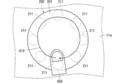
また図41に示されるように、検出対象面201の形状は円形であってもよい。図41の例では、機器ケース11の前面11aから平面透視した場合、検出対象面201の周端部に沿って、当該周端部と重なるように8つの圧力センサ211が位置する。図41の例では、上述の図40の例と同様に、制御部100は、矢印810に示されるような、検出対象面201上を指600が円を描くように移動する操作も、8つの圧力センサ211の検出圧力に基づいて特定することが可能となる。 Further, as shown in FIG. 41, the shape of the detection target surface 201 may be circular. In the example of FIG. 41, eight pressure sensors 211 are located along the peripheral end of the detection target surface 201 so as to overlap the peripheral end when viewed from the front surface 11a of the device case 11. In the example of FIG. 41, similarly to the example of FIG. 40 described above, the control unit 100 also performs eight operations of moving the finger 600 in a circle on the detection target surface 201 as shown by the arrow 810. It is possible to specify based on the detected pressure of the pressure sensor 211.

また、上述した各種の例は、相互に矛盾しない限り組み合わせて適用可能である。そして、例示されていない無数の例が、この開示の範囲から外れることなく想定され得るものと解される。 In addition, the various examples described above can be applied in combination as long as they do not contradict each other. And it is understood that innumerable examples not illustrated can be assumed without departing from the scope of this disclosure.

1 電子機器
100 制御部
120 表示部
121 表示面
130 タッチパネル
200 指紋センサ
201 検出対象面
210 圧力検出装置
211 圧力センサ
1 Electronic device 100 Control unit 120 Display unit 121 Display surface 130 Touch panel 200 Fingerprint sensor 201 Detection target surface 210 Pressure detection device 211 Pressure sensor

Claims (22)

検出対象面を有し、当該検出対象面をさわる指の指紋を検出する指紋センサと、
前記検出対象面にかかる圧力を検出することが可能な複数の圧力センサを有する圧力検出装置と、
前記指紋センサでの指紋検出結果と、前記圧力検出装置での圧力検出結果とに基づいて処理を行う制御部と、
情報を表示する表示面を有する表示部と
を備え、
前記圧力検出結果は、前記検出対象面での前記圧力がかかる位置に応じて変化し、
前記制御部は、
前記表示面が非表示状態の場合、前記圧力検出結果が第1条件を満たすとき、前記指紋検出結果に基づく第1のユーザ認証を行い、
前記表示面が非表示状態の場合、前記圧力検出結果が第2条件を満たすとき、前記第1のユーザ認証を行わずに所定画面を前記表示面に表示し、前記圧力検出結果が前記第2条件を満たさなくなると、前記表示面を非表示状態にする、電子機器。
A fingerprint sensor that has a detection target surface and detects the fingerprint of a finger touching the detection target surface,
A pressure detection device having a plurality of pressure sensors capable of detecting the pressure applied to the surface to be detected, and a pressure detection device.
A control unit that performs processing based on the fingerprint detection result of the fingerprint sensor and the pressure detection result of the pressure detection device.
It is equipped with a display unit having a display surface for displaying information.
The pressure detection result changes according to the position where the pressure is applied on the detection target surface.
The control unit
When the display surface is in the non-display state and the pressure detection result satisfies the first condition, the first user authentication based on the fingerprint detection result is performed.
When the display surface is in the non-display state, when the pressure detection result satisfies the second condition, the predetermined screen is displayed on the display surface without performing the first user authentication, and the pressure detection result is the second. An electronic device that hides the display surface when the conditions are no longer satisfied.
検出対象面を有し、当該検出対象面をさわる指の指紋を検出する指紋センサと、
前記検出対象面にかかる圧力を検出することが可能な複数の圧力センサを有する圧力検出装置と、
前記指紋センサでの指紋検出結果と、前記圧力検出装置での圧力検出結果とに基づいて処理を行う制御部と
を備え、
前記圧力検出結果は、前記検出対象面での前記圧力がかかる位置に応じて変化し、
前記制御部は、前記指紋検出結果に基づく第1のユーザ認証を行い、
前記制御部は、前記第1のユーザ認証が成功した場合、前記第1のユーザ認証の実行のときに得られた前記圧力検出結果に応じたアプリケーションプログラムを実行する、電子機器。
A fingerprint sensor that has a detection target surface and detects the fingerprint of a finger touching the detection target surface,
A pressure detection device having a plurality of pressure sensors capable of detecting the pressure applied to the surface to be detected, and a pressure detection device.
A control unit that performs processing based on the fingerprint detection result of the fingerprint sensor and the pressure detection result of the pressure detection device is provided.
The pressure detection result changes according to the position where the pressure is applied on the detection target surface.
The control unit performs the first user authentication based on the fingerprint detection result, and performs the first user authentication.
The control unit is an electronic device that, when the first user authentication is successful, executes an application program according to the pressure detection result obtained at the time of executing the first user authentication.
請求項1及び請求項2のいずれか一つに記載の電子機器であって、
前記制御部は、前記圧力検出装置での前記圧力の検出に応じて前記指紋センサを起動する、電子機器。
The electronic device according to any one of claims 1 and 2.
The control unit is an electronic device that activates the fingerprint sensor in response to the detection of the pressure by the pressure detection device.
請求項1乃至請求項3のいずれか一つに記載の電子機器であって、
前記制御部は、前記圧力検出結果に基づいて、前記検出対象面に対する操作を特定し、特定した操作に応じた処理を行う、電子機器。
The electronic device according to any one of claims 1 to 3.
The control unit is an electronic device that identifies an operation on the surface to be detected based on the pressure detection result and performs a process according to the specified operation.
請求項4に記載の電子機器であって、
前記制御部は、前記圧力検出結果に基づいて、前記検出対象面に対する操作の速さ、方向及び強さの少なくとも一つを特定する、電子機器。
The electronic device according to claim 4.
The control unit is an electronic device that specifies at least one of the speed, direction, and strength of the operation with respect to the detection target surface based on the pressure detection result.
請求項1に記載の電子機器であって、
前記制御部は、前記圧力検出結果に基づいて、前記検出対象面に対する操作を特定し、特定した操作に応じた処理を行い、
前記制御部は、前記操作に応じて前記表示部の表示を制御する、電子機器。
The electronic device according to claim 1.
The control unit identifies an operation on the detection target surface based on the pressure detection result, and performs a process according to the specified operation.
The control unit is an electronic device that controls the display of the display unit in response to the operation.
請求項4乃至請求項6のいずれか一つに記載の電子機器であって、
前記制御部は、前記操作に応じたアプリケーションプログラムを実行する、電子機器。
The electronic device according to any one of claims 4 to 6.
The control unit is an electronic device that executes an application program corresponding to the operation.
請求項1に記載の電子機器であって、
前記表示面に対する操作入力を検出する検出部を備え、
前記制御部は、
前記操作入力に応じた処理を行い、
前記圧力検出装置での前記圧力の検出中に、前記表示面の少なくとも一部に対する前記操作入力を無効にする、電子機器。
The electronic device according to claim 1.
A detector for detecting an operation input to the display surface is provided.
The control unit
Perform processing according to the operation input
An electronic device that disables the operational input to at least a portion of the display surface during the detection of the pressure by the pressure detector.
請求項8に記載の電子機器であって、
前記表示面は、
前記圧力検出装置での前記圧力の検出中に、それに対する前記操作入力が無効にされない第1部分と、
前記圧力検出装置での前記圧力の検出中に、それに対する前記操作入力が無効にされ、前記第1部分よりも前記検出対象面に近い場所に位置する第2部分と
を有する、電子機器。
The electronic device according to claim 8.
The display surface is
During the detection of the pressure by the pressure detector, the first part in which the operation input for the pressure is not invalidated, and
An electronic device having a second portion located closer to the detection target surface than the first portion, with the operation input to it disabled during the detection of the pressure by the pressure detector.
請求項2に記載の電子機器であって、
ユーザに通知を行う通知部を備える、電子機器。
The electronic device according to claim 2.
An electronic device provided with a notification unit that notifies a user.
請求項10に記載の電子機器であって、
前記制御部は、前記第1のユーザ認証を行う場合に、前記検出対象面での前記指の位置についての基準位置からのずれを、前記圧力検出結果に基づいて特定し、当該ずれを前記通知部に通知させる、電子機器。
The electronic device according to claim 10.
When performing the first user authentication, the control unit identifies a deviation from the reference position of the finger position on the detection target surface based on the pressure detection result, and notifies the deviation. An electronic device that notifies the department.
請求項11に記載の電子機器であって、
前記通知部は、前記ずれを通知する場合、前記位置の変更を案内する案内情報を通知する、電子機器。
The electronic device according to claim 11.
When notifying the deviation, the notification unit is an electronic device that notifies guidance information for guiding a change in the position.
請求項11及び請求項12のいずれか一つに記載の電子機器であって、
前記制御部は、前記第1のユーザ認証が失敗したときに、前記ずれを前記通知部に通知させる、電子機器。
The electronic device according to any one of claims 11 and 12.
The control unit is an electronic device that notifies the notification unit of the deviation when the first user authentication fails.
請求項10乃至請求項13のいずれか一つに記載の電子機器であって、
前記制御部は、
前記第1のユーザ認証を行う場合に、前記圧力検出結果に基づいて、前記圧力が前記第1のユーザ認証にとって適切か否かを判定する判定処理を実行し、
前記判定処理において、前記圧力が適切でないと判定したとき、前記圧力が適切でないことを前記通知部に通知させる、電子機器。
The electronic device according to any one of claims 10 to 13.
The control unit
When performing the first user authentication, a determination process for determining whether or not the pressure is appropriate for the first user authentication is executed based on the pressure detection result.
An electronic device that causes the notification unit to notify that the pressure is not appropriate when it is determined in the determination process that the pressure is not appropriate.
請求項14に記載の電子機器であって、
前記制御部は、前記第1のユーザ認証が失敗したときに、前記圧力が適切でないことを前記通知部に通知させる、電子機器。
The electronic device according to claim 14.
The control unit is an electronic device that causes the notification unit to notify that the pressure is not appropriate when the first user authentication fails.
請求項14及び請求項15のいずれか一つに記載の電子機器であって、
前記制御部は、
前記指紋センサで得られる指紋情報を、前記第1のユーザ認証で使用される基準指紋情報として前記電子機器に登録し、
前記基準指紋情報を登録する場合に得られる前記圧力検出結果に基づいて、前記判定処理で使用される基準圧力を設定する、電子機器。
The electronic device according to any one of claims 14 and 15.
The control unit
The fingerprint information obtained by the fingerprint sensor is registered in the electronic device as the reference fingerprint information used in the first user authentication.
An electronic device that sets a reference pressure used in the determination process based on the pressure detection result obtained when the reference fingerprint information is registered.
請求項2及び請求項10のいずれか一つに記載の電子機器であって、
前記制御部は、前記指紋検出結果及び前記圧力検出結果に基づく前記第1のユーザ認証を行う、電子機器。
The electronic device according to any one of claims 2 and 10.
The control unit is an electronic device that performs the first user authentication based on the fingerprint detection result and the pressure detection result.
請求項2及び請求項10のいずれか一つに記載の電子機器であって、
前記制御部は、前記第1のユーザ認証が失敗した場合、前記第1のユーザ認証の実行後に得られる前記圧力検出結果に基づく第2のユーザ認証を行う、電子機器。
The electronic device according to any one of claims 2 and 10.
The control unit is an electronic device that, when the first user authentication fails, performs a second user authentication based on the pressure detection result obtained after the execution of the first user authentication.
検出対象面を有し、当該検出対象面をさわる指の指紋を検出する指紋センサと、前記検出対象面にかかる圧力を検出することが可能な複数の圧力センサを有する圧力検出装置と、情報を表示する表示面を有する表示部とを備え、前記圧力検出装置での圧力検出結果が、前記検出対象面での前記圧力がかかる位置に応じて変化する電子機器を制御する制御プログラムであって、
前記電子機器に、
前記表示面が非表示状態の場合、前記圧力検出結果が第1条件を満たすとき、前記指紋センサでの指紋検出結果に基づく第1のユーザ認証を行う工程と、
前記表示面が非表示状態の場合、前記圧力検出結果が第2条件を満たすとき、前記第1のユーザ認証を行わずに所定画面を前記表示面に表示し、前記圧力検出結果が前記第2条件を満たさなくなると、前記表示面を非表示状態にする工程と
を実行させる制御プログラム。
Information includes a fingerprint sensor having a detection target surface and detecting a finger fingerprint touching the detection target surface, and a pressure detection device having a plurality of pressure sensors capable of detecting the pressure applied to the detection target surface. A control program having a display unit having a display surface for displaying, and controlling an electronic device whose pressure detection result by the pressure detection device changes according to a position where the pressure is applied on the detection target surface.
To the electronic device
When the display surface is in the non-display state and the pressure detection result satisfies the first condition, the step of performing the first user authentication based on the fingerprint detection result of the fingerprint sensor and the step of performing the first user authentication.
When the display surface is in the non-display state, when the pressure detection result satisfies the second condition, the predetermined screen is displayed on the display surface without performing the first user authentication, and the pressure detection result is the second. A control program that executes a step of hiding the display surface when the conditions are no longer satisfied.
検出対象面を有し、当該検出対象面をさわる指の指紋を検出する指紋センサと、前記検出対象面にかかる圧力を検出することが可能な複数の圧力センサを有する圧力検出装置とを備え、前記圧力検出装置での圧力検出結果が、前記検出対象面での前記圧力がかかる位置に応じて変化する電子機器を制御する制御プログラムであって、
前記電子機器に、
前記指紋センサでの指紋検出結果に基づく第1のユーザ認証を行う工程と、
前記第1のユーザ認証が成功した場合、前記第1のユーザ認証の実行のときに得られた前記圧力検出結果に応じたアプリケーションプログラムを実行する工程と
を実行させる制御プログラム。
A fingerprint sensor having a detection target surface and detecting a finger fingerprint touching the detection target surface, and a pressure detection device having a plurality of pressure sensors capable of detecting the pressure applied to the detection target surface are provided. A control program for controlling an electronic device in which the pressure detection result of the pressure detection device changes according to the position where the pressure is applied on the detection target surface.
To the electronic device
The process of performing the first user authentication based on the fingerprint detection result of the fingerprint sensor and
A control program for executing a step of executing an application program according to the pressure detection result obtained at the time of executing the first user authentication when the first user authentication is successful.
検出対象面を有し、当該検出対象面をさわる指の指紋を検出する指紋センサと、前記検出対象面にかかる圧力を検出することが可能な複数の圧力センサを有する圧力検出装置と、情報を表示する表示面を有する表示部とを備え、前記圧力検出装置での圧力検出結果が、前記検出対象面での前記圧力がかかる位置に応じて変化する電子機器の動作方法であって、
前記表示面が非表示状態の場合、前記圧力検出結果が第1条件を満たすとき、前記指紋センサでの指紋検出結果に基づく第1のユーザ認証を行う工程と、
前記表示面が非表示状態の場合、前記圧力検出結果が第2条件を満たすとき、前記第1のユーザ認証を行わずに所定画面を前記表示面に表示し、前記圧力検出結果が前記第2条件を満たさなくなると、前記表示面を非表示状態にする工程と
を備える、電子機器の動作方法。
Information includes a fingerprint sensor having a detection target surface and detecting a finger fingerprint touching the detection target surface, and a pressure detection device having a plurality of pressure sensors capable of detecting the pressure applied to the detection target surface. It is an operation method of an electronic device including a display unit having a display surface for displaying, and the pressure detection result by the pressure detection device changes according to the position where the pressure is applied on the detection target surface.
When the display surface is in the non-display state and the pressure detection result satisfies the first condition, the step of performing the first user authentication based on the fingerprint detection result of the fingerprint sensor and the step of performing the first user authentication.
When the display surface is in the non-display state, when the pressure detection result satisfies the second condition, the predetermined screen is displayed on the display surface without performing the first user authentication, and the pressure detection result is the second. A method of operating an electronic device, comprising a step of hiding the display surface when the conditions are no longer satisfied.
検出対象面を有し、当該検出対象面をさわる指の指紋を検出する指紋センサと、前記検出対象面にかかる圧力を検出することが可能な複数の圧力センサを有する圧力検出装置とを備え、前記圧力検出装置での圧力検出結果が、前記検出対象面での前記圧力がかかる位置に応じて変化する電子機器の動作方法であって、
前記指紋センサでの指紋検出結果に基づく第1のユーザ認証を行う工程と、
前記第1のユーザ認証が成功した場合、前記第1のユーザ認証の実行のときに得られた前記圧力検出結果に応じたアプリケーションプログラムを実行する工程と
を備える電子機器の動作方法。
A fingerprint sensor having a detection target surface and detecting a finger fingerprint touching the detection target surface, and a pressure detection device having a plurality of pressure sensors capable of detecting the pressure applied to the detection target surface are provided. A method of operating an electronic device in which the pressure detection result of the pressure detection device changes according to the position where the pressure is applied on the detection target surface.
The process of performing the first user authentication based on the fingerprint detection result of the fingerprint sensor and
A method of operating an electronic device including a step of executing an application program according to the pressure detection result obtained at the time of executing the first user authentication when the first user authentication is successful.
JP2018061904A 2018-03-28 2018-03-28 How to operate electronic devices, control programs and electronic devices Active JP6987687B2 (en)

Priority Applications (2)

Application Number Priority Date Filing Date Title
JP2018061904A JP6987687B2 (en) 2018-03-28 2018-03-28 How to operate electronic devices, control programs and electronic devices
US16/365,494 US20190303549A1 (en) 2018-03-28 2019-03-26 Electronic device, controller, and operation method of electronic device

Applications Claiming Priority (1)

Application Number Priority Date Filing Date Title
JP2018061904A JP6987687B2 (en) 2018-03-28 2018-03-28 How to operate electronic devices, control programs and electronic devices

Publications (2)

Publication Number Publication Date
JP2019175090A JP2019175090A (en) 2019-10-10
JP6987687B2 true JP6987687B2 (en) 2022-01-05

Family

ID=68055011

Family Applications (1)

Application Number Title Priority Date Filing Date
JP2018061904A Active JP6987687B2 (en) 2018-03-28 2018-03-28 How to operate electronic devices, control programs and electronic devices

Country Status (2)

Country Link
US (1) US20190303549A1 (en)
JP (1) JP6987687B2 (en)

Families Citing this family (5)

* Cited by examiner, † Cited by third party
Publication number Priority date Publication date Assignee Title
US11132707B2 (en) * 2018-04-25 2021-09-28 At&T Intellectual Property I, L.P. Blockchain solution for an automated advertising marketplace
CN109144360B (en) * 2018-05-31 2021-04-23 北京小米移动软件有限公司 Screen lighting method, electronic device, and storage medium
EP3644202B1 (en) * 2018-10-26 2023-10-04 IDEMIA France Biometric-secured non-biometric applications on a card
WO2022269964A1 (en) * 2021-06-25 2022-12-29 ソニーグループ株式会社 Information processing device, information processing method, and program
US11830281B2 (en) * 2021-08-12 2023-11-28 Samsung Electronics Co., Ltd. Electronic device including a fingerprint sensor

Family Cites Families (9)

* Cited by examiner, † Cited by third party
Publication number Priority date Publication date Assignee Title
JP4252994B2 (en) * 2005-12-26 2009-04-08 株式会社日立製作所 Mobile phone
JP4963388B2 (en) * 2006-09-12 2012-06-27 日立オムロンターミナルソリューションズ株式会社 Biometric authentication device and operation guidance notification method
JP2015169948A (en) * 2014-03-04 2015-09-28 シャープ株式会社 Information processing device, information processing method, and information processing program
JP6177729B2 (en) * 2014-06-26 2017-08-09 京セラ株式会社 Electronics
US9390308B2 (en) * 2014-09-12 2016-07-12 Blackberry Limited Fingerprint scanning method
KR102481643B1 (en) * 2017-01-31 2022-12-28 삼성전자주식회사 Electric device and method for controlling display
KR102364678B1 (en) * 2017-06-20 2022-02-18 엘지전자 주식회사 Mobile terminal
JP6266833B1 (en) * 2017-07-28 2018-01-24 京セラ株式会社 Electronic device, program, and control method
KR102496531B1 (en) * 2018-01-24 2023-02-07 삼성전자주식회사 Method for providing fingerprint recognition, electronic apparatus and storage medium

Also Published As

Publication number Publication date
JP2019175090A (en) 2019-10-10
US20190303549A1 (en) 2019-10-03

Similar Documents

Publication Publication Date Title
JP6987687B2 (en) How to operate electronic devices, control programs and electronic devices
CN107402663B (en) Fingerprint verification method and electronic device for executing the method
CN107810470B (en) Portable device and method for changing screen thereof
US9973685B2 (en) Mobile terminal and method of controlling the same
JP6940353B2 (en) Electronics
RU2605359C2 (en) Touch control method and portable terminal supporting same
EP2687943B1 (en) Mobile terminal device and operation method.
US20190130087A1 (en) Electronic apparatus, control device, and non-transitory computer readable storage medium
CN110858860B (en) Electronic device control responsive to finger rotation on a fingerprint sensor and corresponding method
CN109491573B (en) Electronic device control method and electronic device for executing the method
US10289887B2 (en) Electronic apparatus, operating method of electronic apparatus, and recording medium
US11354031B2 (en) Electronic apparatus, computer-readable non-transitory recording medium, and display control method for controlling a scroll speed of a display screen
JP2015064680A (en) Electronic device, control method thereof, and control program thereof
JP2018160239A (en) Touch input device and control method thereof
JP6871846B2 (en) Electronics and control methods
JP6616379B2 (en) Electronics
JP7034856B2 (en) Electronic devices, control programs and display control methods
JP2018014111A (en) Electronic apparatus
JP2019144724A (en) Electronic apparatus and control method
JP6067245B2 (en) Mobile phone, control method, and computer program
JP5763726B2 (en) Electronic device, electronic device control method, and electronic device control program
JP2017069990A (en) Electronic apparatus
JP2013073512A (en) Device, method, and program

Legal Events

Date Code Title Description
A621 Written request for application examination

Free format text: JAPANESE INTERMEDIATE CODE: A621

Effective date: 20200417

A977 Report on retrieval

Free format text: JAPANESE INTERMEDIATE CODE: A971007

Effective date: 20210129

A131 Notification of reasons for refusal

Free format text: JAPANESE INTERMEDIATE CODE: A131

Effective date: 20210209

A521 Request for written amendment filed

Free format text: JAPANESE INTERMEDIATE CODE: A523

Effective date: 20210305

A131 Notification of reasons for refusal

Free format text: JAPANESE INTERMEDIATE CODE: A131

Effective date: 20210817

A521 Request for written amendment filed

Free format text: JAPANESE INTERMEDIATE CODE: A523

Effective date: 20211001

TRDD Decision of grant or rejection written
A01 Written decision to grant a patent or to grant a registration (utility model)

Free format text: JAPANESE INTERMEDIATE CODE: A01

Effective date: 20211102

A61 First payment of annual fees (during grant procedure)

Free format text: JAPANESE INTERMEDIATE CODE: A61

Effective date: 20211201

R150 Certificate of patent or registration of utility model

Ref document number: 6987687

Country of ref document: JP

Free format text: JAPANESE INTERMEDIATE CODE: R150