JP6986825B2 - How to store the fuel cell coolant container and fuel cell coolant - Google Patents
How to store the fuel cell coolant container and fuel cell coolant Download PDFInfo
- Publication number
- JP6986825B2 JP6986825B2 JP2015225551A JP2015225551A JP6986825B2 JP 6986825 B2 JP6986825 B2 JP 6986825B2 JP 2015225551 A JP2015225551 A JP 2015225551A JP 2015225551 A JP2015225551 A JP 2015225551A JP 6986825 B2 JP6986825 B2 JP 6986825B2
- Authority
- JP
- Japan
- Prior art keywords
- layer
- coolant
- fuel cell
- container
- resin
- Prior art date
- Legal status (The legal status is an assumption and is not a legal conclusion. Google has not performed a legal analysis and makes no representation as to the accuracy of the status listed.)
- Active
Links
Images


Classifications
-
- Y—GENERAL TAGGING OF NEW TECHNOLOGICAL DEVELOPMENTS; GENERAL TAGGING OF CROSS-SECTIONAL TECHNOLOGIES SPANNING OVER SEVERAL SECTIONS OF THE IPC; TECHNICAL SUBJECTS COVERED BY FORMER USPC CROSS-REFERENCE ART COLLECTIONS [XRACs] AND DIGESTS
- Y02—TECHNOLOGIES OR APPLICATIONS FOR MITIGATION OR ADAPTATION AGAINST CLIMATE CHANGE
- Y02E—REDUCTION OF GREENHOUSE GAS [GHG] EMISSIONS, RELATED TO ENERGY GENERATION, TRANSMISSION OR DISTRIBUTION
- Y02E60/00—Enabling technologies; Technologies with a potential or indirect contribution to GHG emissions mitigation
- Y02E60/30—Hydrogen technology
- Y02E60/50—Fuel cells
Description
本発明は、燃料電池用冷却液収容容器及びそれを用いた燃料電池用冷却液の保管方法に関する。より詳細には、保管後の燃料電池用冷却液の電気伝導率の上昇が小さく、初期の電気伝導率を維持することができる燃料電池用冷却液収容容器及びそれを用いた燃料電池用冷却液の保管方法に関する。 The present invention relates to a fuel cell coolant container and a method for storing the fuel cell coolant using the container. More specifically, a fuel cell coolant accommodating container capable of maintaining the initial electrical conductivity with a small increase in the electric conductivity of the fuel cell coolant after storage and a fuel cell coolant using the same. Regarding the storage method of.
燃料電池は、一般に発電単位である単セルを多数積層した構造のスタックとして構成されている。発電時にはスタックから熱が発生するので、このスタックを冷却するために数セル毎に冷却板が挿入されている。この冷却板内部には冷却液通路が形成されており、この通路を冷却液が流れることにより、スタックが冷却される。 A fuel cell is generally configured as a stack having a structure in which a large number of single cells, which are power generation units, are stacked. Since heat is generated from the stack during power generation, a cooling plate is inserted every few cells to cool the stack. A coolant passage is formed inside the cooling plate, and the coolant flows through the passage to cool the stack.
燃料電池用冷却液(以下、単に「冷却液」という。)は、発電を実行しているスタック内を循環してスタックを冷却する。よって、冷却液の電気伝導率が高いと、スタックで生じた電気が冷却液側へと流れて電気を損失し、当該燃料電池における発電力を低下させる。そこで、従来の冷却液には導電率が低い、換言すれば電気絶縁性が高い純水が使用されている。また、冷却液には通常、凍結防止のためのグリコール類又はアルコール類が添加されている。このような水系の冷却液を運搬及び保管する場合、金属製容器では錆が生じるおそれがある。この弊害を避けるため、従来、冷却液は、ポリエチレン等の樹脂製容器に収容して運搬及び保管されていた。 The fuel cell coolant (hereinafter, simply referred to as “coolant”) circulates in the stack executing power generation to cool the stack. Therefore, when the electric conductivity of the coolant is high, the electricity generated in the stack flows to the coolant side and loses electricity, which reduces the power generation in the fuel cell. Therefore, pure water having low conductivity, in other words, high electrical insulation, is used as the conventional coolant. In addition, glycols or alcohols for preventing freezing are usually added to the coolant. When transporting and storing such an aqueous coolant, rust may occur in the metal container. In order to avoid this adverse effect, the coolant has conventionally been transported and stored in a resin container such as polyethylene.
冷却液の製造から使用までの期間は状況によって様々である。例えば、燃料電池搭載車のディーラー及び自動車修理工場では、必要に応じて冷却液の補充が行われることから、冷却液がストックされている。このような所では、冷却液の購入から補充までの期間が長くなることもあり、その結果、冷却液の保管が長期間に及ぶことがある。一方、燃料電池搭載車等の製造現場では、通常、冷却液は短期間のうちに使用される。しかし、コスト等の観点から、冷却液の長期保管が可能であることが望ましい。 The period from production to use of the coolant varies depending on the situation. For example, at dealers of vehicles equipped with fuel cells and automobile repair shops, the coolant is replenished as needed, so that the coolant is stocked. In such places, the period from the purchase of the coolant to the replenishment may be long, and as a result, the storage of the coolant may be extended for a long period of time. On the other hand, at a manufacturing site such as a vehicle equipped with a fuel cell, the coolant is usually used in a short period of time. However, from the viewpoint of cost and the like, it is desirable that the coolant can be stored for a long period of time.
本発明者らは、冷却液の保管後の性質について研究する過程で、保管中に冷却液の電気伝導率が高くなる現象が認められることを新たに確認した。その結果、本発明者らは、冷却液の長期保管により、冷却液の電気伝導率の上昇に起因して燃料電池における発電力が低下するおそれがあるという技術的課題があることを新たに見出した。 In the process of studying the properties of the coolant after storage, the present inventors have newly confirmed that a phenomenon in which the electrical conductivity of the coolant increases during storage is observed. As a result, the present inventors have newly found that there is a technical problem that the power generation in the fuel cell may decrease due to the increase in the electric conductivity of the coolant due to the long-term storage of the coolant. rice field.
本発明者らは、この技術的課題に着目して鋭意研究を重ねた結果、特定の構成の容器を用いることにより、保管後の冷却液の電気伝導率の上昇を抑制することができることを見出し、本発明を完成させるに至った。 As a result of diligent research focusing on this technical problem, the present inventors have found that it is possible to suppress an increase in the electric conductivity of the coolant after storage by using a container having a specific configuration. , The present invention has been completed.
本発明は、保管後の冷却液の電気伝導率の上昇が小さく、初期の電気伝導率を維持することができる冷却液収容容器及びそれを用いた冷却液の保管方法を提供することを目的とする。 An object of the present invention is to provide a cooling liquid storage container capable of maintaining the initial electric conductivity with a small increase in the electric conductivity of the cooling liquid after storage, and a method for storing the cooling liquid using the same. do.
上記目的を達成するため、本発明は、樹脂で構成される内層と、該内層の外側表面に設けられた金属層と、を有する冷却液収容容器及びそれを用いた冷却液の保存方法をその要旨とする。 In order to achieve the above object, the present invention comprises a cooling liquid storage container having an inner layer made of a resin and a metal layer provided on the outer surface of the inner layer, and a method for storing the cooling liquid using the same. It is a summary.
本発明の冷却液収容容器及び冷却液の保存方法によれば、保管後の冷却液の電気伝導率の上昇を抑制することにより、かかる冷却液を使用した燃料電池の発電力の低下を抑制することができる。 According to the coolant accommodating container and the method for storing the coolant of the present invention, the decrease in the electric power generation of the fuel cell using the coolant is suppressed by suppressing the increase in the electric conductivity of the coolant after storage. be able to.
以下、本発明の冷却液収容容器及び冷却液の保存方法を更に詳しく説明する。尚、上記のように、本明細書において、特段の記載がない限り、「冷却液」は「燃料電池用冷却液」の意味である。 Hereinafter, the coolant container and the method for storing the coolant of the present invention will be described in more detail. As described above, unless otherwise specified in the present specification, "coolant" means "fuel cell coolant".
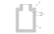
本発明の冷却液収容容器の一例を図1に示す。本発明の一例の容器1aは、樹脂で構成される内層11と、該内層11の外側表面に設けられた金属層12と、を有する。
An example of the coolant container of the present invention is shown in FIG. The
前記内層11は、容器1の内部に面した層であり、内層表面111は、冷却液2と接する。本発明の作用効果を阻害しない限り、前記内層の構造には特に限定はない。前記内層は図1に示すように1層でもよく、図2に示すように2層以上の多層(図2の11A及び11B)で構成されていてもよい。
The
前記内層を構成する樹脂の種類には特に限定はない。前記樹脂は単独重合体でもよく、共重合体でもよい。前記樹脂として具体的には、例えば、ポリオレフィン樹脂(例えば、ポリエチレン、ポリプロピレン)、ポリスチレン、ポリエステル樹脂(例えば、ポリエチレンテレフタレート(PET)、ポリブチレンテレフタレート(PBT)、ポリエチレンナフタレート(PEN))、ポリ塩化ビニリデン、ポリビニルアルコール樹脂、ポリアミド、ポリアクリロニトリル、ポリカーボネートが挙げられる。前記ポリエチレンは、高密度ポリエチレン(比重0.92〜0.96、荷重たわみ温度 130℃以下。)、低密度ポリエチレン(比重0.91〜0.92、荷重たわみ温度100℃ 以下)超低密度ポリエチレン(比重0.9未満)、直鎖状低密度ポリエチレン(比重0.94未満)、超高分子量(例えば、分子量が100万以上)ポリエチレンのいずれでもよい。 The type of resin constituting the inner layer is not particularly limited. The resin may be a homopolymer or a copolymer. Specifically, as the resin, for example, a polyolefin resin (for example, polyethylene, polypropylene), polystyrene, a polyester resin (for example, polyethylene terephthalate (PET), polybutylene terephthalate (PBT), polyethylene naphthalate (PEN)), polychloride. Examples thereof include vinylidene, polyvinyl alcohol resin, polyamide, polyacrylonitrile, and polycarbonate. The polyethylene is high-density polyethylene (specific gravity 0.92 to 0.96, deflection temperature under load 130 ° C or less), low-density polyethylene (specific gravity 0.91 to 0.92, deflection temperature under load 100 ° C or less), ultra-low density polyethylene. It may be any of (specific gravity less than 0.9), linear low density polyethylene (specific gravity less than 0.94), and ultrahigh molecular weight (for example, molecular weight of 1 million or more) polyethylene.
前記内層11は、樹脂材料で構成されるが、本発明の作用効果を阻害しない限り、内層中に他の成分を含んでいてもよい。該他の成分として具体的には、例えば、公知の樹脂添加剤が挙げられる。該樹脂添加剤として具体的には、例えば、酸化防止剤、光安定剤、難燃剤、可塑剤、染料、顔料及び着色剤が挙げられる。
The
前記内層11の厚さは、本発明の作用効果を阻害しない限り特に限定はなく、必要に応じて種々の厚さとすることができる。前記内層の厚さは通常、7〜30μmである。
The thickness of the
前記金属層12は、該内層11の外側表面(内側表面111の反対側の表面)に設けられた層である。前記金属層を構成する金属の種類には特に限定はない。該金属として具体的には、例えば、アルミニウムが挙げられる。
The
本発明の作用効果を阻害しない限り、前記金属層の構造には特に限定はない。通常、前記金属層は図1に示すように1層であるが、図3に示すように2層以上の多層(図3の12A及び12B)で構成されていてもよい。また、前記金属層の厚さについても、本発明の作用効果を阻害しない限り特に限定はなく、必要に応じて種々の厚さとすることができる。前記金属層の厚さは通常、7〜25μmである。 The structure of the metal layer is not particularly limited as long as it does not inhibit the action and effect of the present invention. Normally, the metal layer is one layer as shown in FIG. 1, but may be composed of two or more layers (12A and 12B in FIG. 3) as shown in FIG. Further, the thickness of the metal layer is not particularly limited as long as it does not hinder the action and effect of the present invention, and may be various thicknesses as needed. The thickness of the metal layer is usually 7 to 25 μm.
前記内層11の外側表面に前記金属層12を形成する手段には特に限定はない。例えば、前記金属層11を構成する金属箔を形成し、次いで、これを接着剤又はヒートシール性を有する他の樹脂フィルム等により前記内層に張り合わせてもよい。あるいは、前記内層を構成する樹脂材料(例えば、フィルム状又はシート状の樹脂材料)の表面に、化学蒸着、プラズマ蒸着、スパッタリング等により前記金属層を形成してもよい。
The means for forming the
また、前記内層及び金属層の形成と容器の形成の順序にも特に限定はない。前記のように、樹脂材料の一方の表面に金属層を形成した後、これを用いて容器を製造してもよい。あるいは、射出成形又はブロー成形等により、予め樹脂材料から中空容器を製造した後、プラズマ蒸着等により、該中空容器の外側表面に前記金属層を形成してもよい。 Further, the order of forming the inner layer and the metal layer and forming the container is not particularly limited. As described above, a metal layer may be formed on one surface of a resin material and then used to manufacture a container. Alternatively, a hollow container may be manufactured in advance from a resin material by injection molding, blow molding, or the like, and then the metal layer may be formed on the outer surface of the hollow container by plasma vapor deposition or the like.
本発明の容器は、前記内層及び金属層を有する限り、その具体的構成には特に限定はない。本発明の容器の一例を図1〜図5に示す。 As long as the container of the present invention has the inner layer and the metal layer, the specific structure thereof is not particularly limited. An example of the container of the present invention is shown in FIGS. 1 to 5.
図1に示す容器1aは、前記内層11及び前記金属層12が各1層であり、前記金属層12が外層(外部環境と接する層)を構成している。
In the
図2に示す容器1bは、前記内層11が多層構造(11A及び11B)である。また、前記金属層12は1層であり、これが外層を構成している。前記内層11が多層構造の場合、少なくとも最内層(燃料電池用冷却液と接する層、図2では内層11Aに相当する。)を構成する材料が樹脂であり、本発明の作用効果を阻害しない限り、内層を構成する材料には特に限定はない。通常、内層11を構成する各層は全て樹脂層である。この場合、各樹脂層を構成する樹脂材料にも特に限定はない。該樹脂層は同じ樹脂材料でもよく、異なる樹脂材料でもよい。
In the
図3に示す容器1cは、前記金属層12が多層構造(12A及び12B)である。前記金属層が多層構造である場合、本発明の作用効果を阻害しない限り、各金属層を構成する金属材料には特に限定はない。該金属層は異なる種類の金属層で構成されてもよく、同じ種類の金属層で構成されていてもよい。
In the
図4に示す容器1dは、前記内層11が多層構造(11A及び11B)であり、且つ前記金属層12が多層構造(12A及び12B)である。前記内層11及び金属層12については、容器1B及び1Cに関する説明が妥当する。
In the
図5に示す容器1eは、前記金属層12の外側表面に更に他の外層13を有する。即ち、本発明の容器は、前記金属層の外側表面に更に他の外層を有していてもよい。該他の外層の材質は、本発明の作用効果を阻害しない限り特に限定はない。該他の外層は通常、樹脂層である。該樹脂層を構成する樹脂として具体的には、例えば、前記内層を構成する樹脂として例示された樹脂が挙げられる。前記内層を構成する樹脂と前記他の外層を構成する樹脂は、同じ樹脂でもよく、異なる樹脂でもよい。前記内層を構成する樹脂と前記他の外層を構成する樹脂の組み合わせとしては、例えば、ポリオレフィン樹脂とポリエステル樹脂の組み合わせが挙げられる。図5に示す容器1eにおいて、通常、内層11がポリエステル樹脂であり、他の外層13がポリオレフィン樹脂であるが、逆でもよい。
The
図5(a)に示すように、前記他の外層は1層でもよく、あるいは、図5(b)に示すように多層構造(13A及び13B)でもよい。前記他の外層が多層構造である場合、本発明の作用効果を阻害しない限り、各層を構成する材料には特に限定はない。通常、各層は樹脂層であるが、樹脂層と金属層との組み合わせでもよい。 As shown in FIG. 5A, the other outer layer may be a single layer, or may be a multilayer structure (13A and 13B) as shown in FIG. 5B. When the other outer layer has a multi-layer structure, the material constituting each layer is not particularly limited as long as the action and effect of the present invention are not impaired. Normally, each layer is a resin layer, but a combination of a resin layer and a metal layer may be used.
本発明の容器において、前記内層、金属層、及び他の外層が多層構造の場合、各層を一体化する方法には特に限定はない。例えば、多層構造を構成する層を、接着剤又はヒートシール性を有する他の樹脂フィルムにより一体化することができる。この場合、正確には、多層構造を構成する層の間に接着層又はヒートシール性樹脂層が形成されるが、図1〜図5では、このような接着層又はヒートシール性樹脂層の記載を省略している。即ち、図1〜図5で例示した容器には、多層構造の各層の間の少なくともいずれかに、接着層又はヒートシール性樹脂層を有する態様も含まれる。 In the container of the present invention, when the inner layer, the metal layer, and the other outer layer have a multi-layer structure, the method of integrating each layer is not particularly limited. For example, the layers constituting the multilayer structure can be integrated with an adhesive or another resin film having a heat-sealing property. In this case, to be precise, an adhesive layer or a heat-sealing resin layer is formed between the layers constituting the multilayer structure, and FIGS. 1 to 5 show the description of such an adhesive layer or the heat-sealing resin layer. Is omitted. That is, the container illustrated in FIGS. 1 to 5 also includes an embodiment in which at least one of the layers of the multilayer structure has an adhesive layer or a heat-sealing resin layer.
本発明の容器の大きさには特に限定はない。本発明の容器は用途に応じて種々の大きさにすることができる。 The size of the container of the present invention is not particularly limited. The container of the present invention can be made into various sizes depending on the application.
本発明の保管方法は、本発明の容器に冷却液を収容する。本発明の「保管」には、単に冷却液をそのまま(冷却液を冷却液として使用しない態様で)保管する場合(単純保管)だけでなく、冷却液として使用しながら保管する場合(使用保管)の両者を含む。例えば、本発明の容器を、車両搭載用燃料電池と共に車両に搭載し、冷却液を冷却液として使用しながら保管する場合も含む。 In the storage method of the present invention, the coolant is stored in the container of the present invention. The "storage" of the present invention includes not only the case where the coolant is stored as it is (in a mode in which the coolant is not used as the coolant) (simple storage) but also the case where the coolant is stored while being used as the coolant (use storage). Including both. For example, the case where the container of the present invention is mounted on a vehicle together with a fuel cell for mounting on a vehicle and the coolant is stored while being used as the coolant is also included.
本発明の保管方法は、本発明の容器に冷却液を収容する限り、具体的な保管方法及び保管条件には特に限定はない。保管方法及び保管条件は、必要に応じて適宜の方法及び条件を設定することができる。また、前記冷却液の組成にも特に限定はなく、例えば、公知の冷却液を用いることができる。前記冷却液として具体的には、例えば、水(イオン交換水等)、又は水(イオン交換水等)とグリコール類及び/若しくはアルコール類とを含有する冷却液が挙げられる。 The storage method of the present invention is not particularly limited in the specific storage method and storage conditions as long as the cooling liquid is contained in the container of the present invention. As for the storage method and storage conditions, appropriate methods and conditions can be set as necessary. Further, the composition of the coolant is not particularly limited, and for example, a known coolant can be used. Specific examples of the coolant include water (ion-exchanged water and the like) or a coolant containing water (ion-exchanged water and the like) and glycols and / or alcohols.
本発明の容器及び保管方法は、特許請求の範囲に記載された範囲内で自由に変更することができる。 The container and storage method of the present invention can be freely changed within the scope of the claims.
以下、実施例により本発明を具体的に説明する。尚、本発明は、実施例に示す形態に限定されない。本発明の実施形態は、目的及び用途等に応じて、本発明の範囲内で種々変更することができる。 Hereinafter, the present invention will be specifically described with reference to Examples. The present invention is not limited to the embodiment shown in the examples. The embodiments of the present invention can be variously modified within the scope of the present invention according to the purpose, use and the like.
実施例1〜2及び比較例の各容器の組成を表1に示す。各容器の容量はいずれも2Lである。実施例1の容器は、内層がPET(ポリエチレンテレフタレート)12μm、金属層がアルミ箔9μm、外層がONY(ナイロン)15μm及びLLDPE(直鎖状低密度ポリエチレン)160μmで構成されている(最外層がLLDPE)。実施例1の容器は、各層をドライラミネート法により積層して形成した。実施例2の容器は、内層がPET12μm、金属層がアルミ、外層がPET、ONY25μm及びLLDPE180μmで構成されている(最外層がLLDPE。金属層と接しているのがPET)。実施例2の容器は、PET上にアルミを蒸着させたアルミ蒸着PETを用い(厚さ12μm)、これと外層及び内層を構成する各層をドライラミネート法により積層して形成した。
The composition of each container of Examples 1 and 2 and Comparative Example is shown in Table 1. The capacity of each container is 2 L. Container Example 1, the inner layer is PET (polyethylene terephthalate) 12 [mu] m, the metal layer is aluminum foil 9 .mu.m, the outer layer is composed of ONY (nylon) 15 [mu] m and LLDPE (linear low density polyethylene) 160 .mu.m (top the outer layer is LLDPE). The container of Example 1 was formed by laminating each layer by a dry laminating method. Containers Example 2, (PET the outermost layer is in contact with the LLDPE. Metal layer) to the inner layer PET12myuemu, the metal layer is aluminum, the outer layer is PET, ONY25myuemu and are composed of LLDPE180myuemu. The container of Example 2 was formed by using aluminum-deposited PET in which aluminum was vapor-deposited on PET (
実施例1〜2及び比較例1の各容器に、燃料電池用冷却液(シーシーアイ株式会社製、エチレングリコール/イオン交換水)を2L収容した。次いで、温度50℃の条件で該冷却液を保存し、168、336、504及び672時間後の電気伝導率(μS/cm)を導電率計ES−12(株式会社堀場製作所製)により測定した。その結果を表1に示す。 In each of the containers of Examples 1 and 2 and Comparative Example 1, 2 L of a fuel cell coolant (ethylene glycol / ion-exchanged water manufactured by CCI Co., Ltd.) was contained. Next, the coolant was stored under the condition of a temperature of 50 ° C., and the electric conductivity (μS / cm) after 168, 336, 504 and 672 hours was measured with a conductivity meter ES-12 (manufactured by HORIBA, Ltd.). .. The results are shown in Table 1.

表1より、従来の樹脂製容器(比較例)で保管された冷却液は、保管中に電気伝導率が上昇していることが分かる。特に保管から168時間(7日間)の時点で既に電気伝導率が初期の4倍程度の上昇し、672時間(28日間)の時点で初期の8倍まで上昇している。一方、本発明の容器に含まれる実施例1及び2の容器で保存された冷却液は、保管から672時間(28日間)の時点でも依然として初期の電気伝導率を維持している。よって、本発明の容器は、保管中の冷却液の電気伝導率の上昇抑制効果に著しく優れており、冷却液の保存に好適であることが分かる。 From Table 1, it can be seen that the cooling liquid stored in the conventional resin container (comparative example) has an increased electric conductivity during storage. In particular, at 168 hours (7 days) after storage, the electrical conductivity has already increased about 4 times the initial value, and at 672 hours (28 days), it has increased up to 8 times the initial value. On the other hand, the coolant stored in the containers of Examples 1 and 2 contained in the container of the present invention still maintains the initial electrical conductivity even at 672 hours (28 days) after storage. Therefore, it can be seen that the container of the present invention is remarkably excellent in the effect of suppressing an increase in the electric conductivity of the cooling liquid during storage, and is suitable for storing the cooling liquid.
1a〜1e;燃料電池用冷却液収容容器、11;内層、111;内層表面、12;金属層、13;他の外層、2;燃料電池用冷却液。 1a to 1e; fuel cell coolant container, 11; inner layer, 111; inner layer surface, 12; metal layer, 13; other outer layer, 2; fuel cell coolant.
Claims (4)
Priority Applications (1)
| Application Number | Priority Date | Filing Date | Title |
|---|---|---|---|
| JP2015225551A JP6986825B2 (en) | 2015-11-18 | 2015-11-18 | How to store the fuel cell coolant container and fuel cell coolant |
Applications Claiming Priority (1)
| Application Number | Priority Date | Filing Date | Title |
|---|---|---|---|
| JP2015225551A JP6986825B2 (en) | 2015-11-18 | 2015-11-18 | How to store the fuel cell coolant container and fuel cell coolant |
Publications (3)
| Publication Number | Publication Date |
|---|---|
| JP2017097958A JP2017097958A (en) | 2017-06-01 |
| JP2017097958A5 JP2017097958A5 (en) | 2018-09-13 |
| JP6986825B2 true JP6986825B2 (en) | 2021-12-22 |
Family
ID=58817954
Family Applications (1)
| Application Number | Title | Priority Date | Filing Date |
|---|---|---|---|
| JP2015225551A Active JP6986825B2 (en) | 2015-11-18 | 2015-11-18 | How to store the fuel cell coolant container and fuel cell coolant |
Country Status (1)
| Country | Link |
|---|---|
| JP (1) | JP6986825B2 (en) |
Families Citing this family (2)
| Publication number | Priority date | Publication date | Assignee | Title |
|---|---|---|---|---|
| KR101621161B1 (en) * | 2013-09-30 | 2016-05-13 | 주식회사 엘지화학 | Preparing method for thin polarizer, thin polarizer and polarizing plate comprising the same |
| CN114100392A (en) * | 2021-11-15 | 2022-03-01 | 郝建强 | Preparation method of non-contact hydrogen fuel cell cooling liquid |
Family Cites Families (6)
| Publication number | Priority date | Publication date | Assignee | Title |
|---|---|---|---|---|
| JP2005100698A (en) * | 2003-09-22 | 2005-04-14 | Nissan Motor Co Ltd | Storage tank and fuel cell system |
| JP2005129469A (en) * | 2003-10-27 | 2005-05-19 | Toyo Tire & Rubber Co Ltd | Fuel cell |
| JP4573525B2 (en) * | 2003-12-24 | 2010-11-04 | 本田技研工業株式会社 | Solid polymer electrolyte fuel cell |
| JP2005310549A (en) * | 2004-04-21 | 2005-11-04 | Toyota Motor Corp | Conductivity retaining device of cooling liquid |
| CN101478053A (en) * | 2004-11-19 | 2009-07-08 | 东洋制罐株式会社 | Cartridge for methanol fuel cell |
| JP2013131428A (en) * | 2011-12-22 | 2013-07-04 | Panasonic Corp | Battery with cooling part |
-
2015
- 2015-11-18 JP JP2015225551A patent/JP6986825B2/en active Active
Also Published As
| Publication number | Publication date |
|---|---|
| JP2017097958A (en) | 2017-06-01 |
Similar Documents
| Publication | Publication Date | Title |
|---|---|---|
| KR102239167B1 (en) | Vacuum Insulation Material and Method of Manufacturing Same | |
| JP6986825B2 (en) | How to store the fuel cell coolant container and fuel cell coolant | |
| KR101712990B1 (en) | Flexible cell pouch and secondary battery including the same | |
| JP2013225412A (en) | Battery case packaging material for cold molding including biaxially-oriented polybutylene terephthalate film | |
| KR20220123043A (en) | A packaging material for an electrical storage device, a method for manufacturing an electrical storage device using the same, a packaging material for an electrical storage device, and a method for selecting a sealant film used as a sealant layer in the packaging material for an electrical storage device | |
| JP6491271B2 (en) | Ser pouch with excellent moldability | |
| US10723530B2 (en) | Outer packing material for vacuum insulation material, vacuum insulation material, and article provided with vacuum insulation material | |
| JP5998231B2 (en) | Sealing material for vacuum insulation panels with excellent impact resistance and non-flammability | |
| JP2008130548A (en) | Polymer packing material for film battery of multilayer structure and collector also serving as packing material equipped with it | |
| JP6776618B2 (en) | Outer packaging material for vacuum heat insulating material, vacuum heat insulating material, and equipment with vacuum heat insulating material | |
| KR100867996B1 (en) | Multi-layered polymer wrapper for film battery and current collector combined with the wrapper | |
| EP3467900A1 (en) | Battery packaging material and preparation method therefor, battery pack seal cover, battery pack body, power battery and electric vehicle | |
| JP2018059524A (en) | Outer packing material for vacuum heat insulation material, vacuum heat insulation material, and article with vacuum heat insulation material | |
| JP6436758B2 (en) | Power storage device exterior material and power storage device | |
| JP2020176677A (en) | Outer wrapping material for vacuum heat insulation material, vacuum heat insulation material, and article with vacuum heat insulation material | |
| KR102317718B1 (en) | Laminated Structure and Vacuum Insulating Material Including Laminated Structure | |
| KR102316076B1 (en) | Battery Cell Tray Having Volatile Corrosion Inhibitor | |
| JP6094088B2 (en) | Laminate for vacuum insulation | |
| JP6060493B2 (en) | Heat insulating laminated thin film covering the upper surface of the container in the transport container | |
| JP2020063844A (en) | Outer wrapping material for vacuum heat insulation material, vacuum heat insulation material, and item with vacuum heat insulation material | |
| JP2008277135A5 (en) | ||
| JP6119106B2 (en) | Liquid paper container | |
| JP2018059625A (en) | Outer packing material for vacuum heat insulation material, vacuum heat insulation material, and article with vacuum heat insulation material | |
| JP2020008084A (en) | Outer packaging material for vacuum insulation material, vacuum heat insulation material, and articles with vacuum insulation material | |
| US20240042254A1 (en) | Fire extinguishing body and battery pack |
Legal Events
| Date | Code | Title | Description |
|---|---|---|---|
| A521 | Written amendment |
Free format text: JAPANESE INTERMEDIATE CODE: A523 Effective date: 20180803 |
|
| A621 | Written request for application examination |
Free format text: JAPANESE INTERMEDIATE CODE: A621 Effective date: 20180803 |
|
| A131 | Notification of reasons for refusal |
Free format text: JAPANESE INTERMEDIATE CODE: A131 Effective date: 20190528 |
|
| A977 | Report on retrieval |
Free format text: JAPANESE INTERMEDIATE CODE: A971007 Effective date: 20190529 |
|
| A521 | Written amendment |
Free format text: JAPANESE INTERMEDIATE CODE: A523 Effective date: 20190726 |
|
| A131 | Notification of reasons for refusal |
Free format text: JAPANESE INTERMEDIATE CODE: A131 Effective date: 20191218 |
|
| A02 | Decision of refusal |
Free format text: JAPANESE INTERMEDIATE CODE: A02 Effective date: 20200804 |
|
| C60 | Trial request (containing other claim documents, opposition documents) |
Free format text: JAPANESE INTERMEDIATE CODE: C60 Effective date: 20201102 |
|
| C116 | Written invitation by the chief administrative judge to file amendments |
Free format text: JAPANESE INTERMEDIATE CODE: C116 Effective date: 20201117 |
|
| C22 | Notice of designation (change) of administrative judge |
Free format text: JAPANESE INTERMEDIATE CODE: C22 Effective date: 20201117 |
|
| C22 | Notice of designation (change) of administrative judge |
Free format text: JAPANESE INTERMEDIATE CODE: C22 Effective date: 20210216 |
|
| C22 | Notice of designation (change) of administrative judge |
Free format text: JAPANESE INTERMEDIATE CODE: C22 Effective date: 20210420 |
|
| C13 | Notice of reasons for refusal |
Free format text: JAPANESE INTERMEDIATE CODE: C13 Effective date: 20210615 |
|
| A521 | Written amendment |
Free format text: JAPANESE INTERMEDIATE CODE: A523 Effective date: 20210812 |
|
| RD02 | Notification of acceptance of power of attorney |
Free format text: JAPANESE INTERMEDIATE CODE: A7422 Effective date: 20210812 |
|
| RD04 | Notification of resignation of power of attorney |
Free format text: JAPANESE INTERMEDIATE CODE: A7424 Effective date: 20210816 |
|
| C23 | Notice of termination of proceedings |
Free format text: JAPANESE INTERMEDIATE CODE: C23 Effective date: 20211026 |
|
| C03 | Trial/appeal decision taken |
Free format text: JAPANESE INTERMEDIATE CODE: C03 Effective date: 20211124 |
|
| C30A | Notification sent |
Free format text: JAPANESE INTERMEDIATE CODE: C3012 Effective date: 20211124 |
|
| A61 | First payment of annual fees (during grant procedure) |
Free format text: JAPANESE INTERMEDIATE CODE: A61 Effective date: 20211130 |
|
| R150 | Certificate of patent or registration of utility model |
Ref document number: 6986825 Country of ref document: JP Free format text: JAPANESE INTERMEDIATE CODE: R150 |