JP6985876B2 - Imaging device - Google Patents

Imaging device Download PDF

Info

Publication number
JP6985876B2
JP6985876B2 JP2017188267A JP2017188267A JP6985876B2 JP 6985876 B2 JP6985876 B2 JP 6985876B2 JP 2017188267 A JP2017188267 A JP 2017188267A JP 2017188267 A JP2017188267 A JP 2017188267A JP 6985876 B2 JP6985876 B2 JP 6985876B2
Authority
JP
Japan
Prior art keywords
movable member
image pickup
fixing member
vibration
slider
Prior art date
Legal status (The legal status is an assumption and is not a legal conclusion. Google has not performed a legal analysis and makes no representation as to the accuracy of the status listed.)
Active
Application number
JP2017188267A
Other languages
Japanese (ja)
Other versions
JP2019066506A5 (en
JP2019066506A (en
Inventor
正史 木村
Current Assignee (The listed assignees may be inaccurate. Google has not performed a legal analysis and makes no representation or warranty as to the accuracy of the list.)
Canon Inc
Original Assignee
Canon Inc
Priority date (The priority date is an assumption and is not a legal conclusion. Google has not performed a legal analysis and makes no representation as to the accuracy of the date listed.)
Filing date
Publication date
Application filed by Canon Inc filed Critical Canon Inc
Priority to JP2017188267A priority Critical patent/JP6985876B2/en
Priority to US16/142,166 priority patent/US11340469B2/en
Priority to CN201811138374.4A priority patent/CN109586610B/en
Publication of JP2019066506A publication Critical patent/JP2019066506A/en
Publication of JP2019066506A5 publication Critical patent/JP2019066506A5/ja
Application granted granted Critical
Publication of JP6985876B2 publication Critical patent/JP6985876B2/en
Active legal-status Critical Current
Anticipated expiration legal-status Critical

Links

Images

Classifications

    • HELECTRICITY
    • H02GENERATION; CONVERSION OR DISTRIBUTION OF ELECTRIC POWER
    • H02NELECTRIC MACHINES NOT OTHERWISE PROVIDED FOR
    • H02N2/00Electric machines in general using piezoelectric effect, electrostriction or magnetostriction
    • GPHYSICS
    • G02OPTICS
    • G02BOPTICAL ELEMENTS, SYSTEMS OR APPARATUS
    • G02B27/00Optical systems or apparatus not provided for by any of the groups G02B1/00 - G02B26/00, G02B30/00
    • G02B27/64Imaging systems using optical elements for stabilisation of the lateral and angular position of the image
    • G02B27/646Imaging systems using optical elements for stabilisation of the lateral and angular position of the image compensating for small deviations, e.g. due to vibration or shake
    • GPHYSICS
    • G03PHOTOGRAPHY; CINEMATOGRAPHY; ANALOGOUS TECHNIQUES USING WAVES OTHER THAN OPTICAL WAVES; ELECTROGRAPHY; HOLOGRAPHY
    • G03BAPPARATUS OR ARRANGEMENTS FOR TAKING PHOTOGRAPHS OR FOR PROJECTING OR VIEWING THEM; APPARATUS OR ARRANGEMENTS EMPLOYING ANALOGOUS TECHNIQUES USING WAVES OTHER THAN OPTICAL WAVES; ACCESSORIES THEREFOR
    • G03B5/00Adjustment of optical system relative to image or object surface other than for focusing
    • HELECTRICITY
    • H02GENERATION; CONVERSION OR DISTRIBUTION OF ELECTRIC POWER
    • H02NELECTRIC MACHINES NOT OTHERWISE PROVIDED FOR
    • H02N2/00Electric machines in general using piezoelectric effect, electrostriction or magnetostriction
    • H02N2/0005Electric machines in general using piezoelectric effect, electrostriction or magnetostriction producing non-specific motion; Details common to machines covered by H02N2/02 - H02N2/16
    • H02N2/001Driving devices, e.g. vibrators
    • HELECTRICITY
    • H02GENERATION; CONVERSION OR DISTRIBUTION OF ELECTRIC POWER
    • H02NELECTRIC MACHINES NOT OTHERWISE PROVIDED FOR
    • H02N2/00Electric machines in general using piezoelectric effect, electrostriction or magnetostriction
    • H02N2/10Electric machines in general using piezoelectric effect, electrostriction or magnetostriction producing rotary motion, e.g. rotary motors
    • H02N2/14Drive circuits; Control arrangements or methods
    • HELECTRICITY
    • H04ELECTRIC COMMUNICATION TECHNIQUE
    • H04NPICTORIAL COMMUNICATION, e.g. TELEVISION
    • H04N23/00Cameras or camera modules comprising electronic image sensors; Control thereof
    • H04N23/60Control of cameras or camera modules
    • H04N23/66Remote control of cameras or camera parts, e.g. by remote control devices
    • H04N23/663Remote control of cameras or camera parts, e.g. by remote control devices for controlling interchangeable camera parts based on electronic image sensor signals
    • HELECTRICITY
    • H04ELECTRIC COMMUNICATION TECHNIQUE
    • H04NPICTORIAL COMMUNICATION, e.g. TELEVISION
    • H04N23/00Cameras or camera modules comprising electronic image sensors; Control thereof
    • H04N23/60Control of cameras or camera modules
    • H04N23/68Control of cameras or camera modules for stable pick-up of the scene, e.g. compensating for camera body vibrations
    • H04N23/681Motion detection
    • H04N23/6812Motion detection based on additional sensors, e.g. acceleration sensors
    • HELECTRICITY
    • H04ELECTRIC COMMUNICATION TECHNIQUE
    • H04NPICTORIAL COMMUNICATION, e.g. TELEVISION
    • H04N23/00Cameras or camera modules comprising electronic image sensors; Control thereof
    • H04N23/60Control of cameras or camera modules
    • H04N23/68Control of cameras or camera modules for stable pick-up of the scene, e.g. compensating for camera body vibrations
    • H04N23/682Vibration or motion blur correction
    • H04N23/685Vibration or motion blur correction performed by mechanical compensation
    • H04N23/687Vibration or motion blur correction performed by mechanical compensation by shifting the lens or sensor position
    • GPHYSICS
    • G03PHOTOGRAPHY; CINEMATOGRAPHY; ANALOGOUS TECHNIQUES USING WAVES OTHER THAN OPTICAL WAVES; ELECTROGRAPHY; HOLOGRAPHY
    • G03BAPPARATUS OR ARRANGEMENTS FOR TAKING PHOTOGRAPHS OR FOR PROJECTING OR VIEWING THEM; APPARATUS OR ARRANGEMENTS EMPLOYING ANALOGOUS TECHNIQUES USING WAVES OTHER THAN OPTICAL WAVES; ACCESSORIES THEREFOR
    • G03B2205/00Adjustment of optical system relative to image or object surface other than for focusing
    • G03B2205/0007Movement of one or more optical elements for control of motion blur
    • G03B2205/0038Movement of one or more optical elements for control of motion blur by displacing the image plane with respect to the optical axis
    • GPHYSICS
    • G03PHOTOGRAPHY; CINEMATOGRAPHY; ANALOGOUS TECHNIQUES USING WAVES OTHER THAN OPTICAL WAVES; ELECTROGRAPHY; HOLOGRAPHY
    • G03BAPPARATUS OR ARRANGEMENTS FOR TAKING PHOTOGRAPHS OR FOR PROJECTING OR VIEWING THEM; APPARATUS OR ARRANGEMENTS EMPLOYING ANALOGOUS TECHNIQUES USING WAVES OTHER THAN OPTICAL WAVES; ACCESSORIES THEREFOR
    • G03B2205/00Adjustment of optical system relative to image or object surface other than for focusing
    • G03B2205/0053Driving means for the movement of one or more optical element
    • G03B2205/0061Driving means for the movement of one or more optical element using piezoelectric actuators

Description

本発明は撮像装置に関し、特に振動波アクチュエータを用いた撮像装置に関する。 The present invention relates to an image pickup device , and more particularly to an image pickup device using a vibration wave actuator.

近年、撮像装置は高性能化しており、防振機能(手持ち撮影において手振れを抑制することにより長い露光時間でも高解像度に撮影可能な機能)を備えた撮像装置が増えている。また、高速に応答可能であるとともに駆動部の位置を保持可能なアクチュエータとして超音波モータが様々な用途で用いられている。特許文献1には、防振装置に振動型駆動装置を用いるとともに、1軸方向の変位が他の軸に影響を与えないような機構とすることで、2軸方向に移動可能な防振装置が開示されている。特許文献2には、防振装置に駆動装置を用いるとともに、可動部が積層するような構成とすることで2軸方向に移動可能な防振装置が開示されている。 In recent years, image pickup devices have become more sophisticated, and an increasing number of image pickup devices have an anti-vibration function (a function that enables high-resolution shooting even with a long exposure time by suppressing camera shake in handheld shooting). Further, an ultrasonic motor is used in various applications as an actuator capable of responding at high speed and holding the position of a drive unit. In Patent Document 1, a vibration type drive device is used as the vibration isolator, and the mechanism is such that the displacement in the uniaxial direction does not affect the other axes, so that the vibration isolator can move in the biaxial direction. Is disclosed. Patent Document 2 discloses a vibration isolator that can move in two axial directions by using a drive device as the vibration isolator and having a configuration in which movable portions are laminated.

特開2014−142562号公報Japanese Unexamined Patent Publication No. 2014-142562 特開2008−220031号公報Japanese Unexamined Patent Publication No. 2008-220031

しかしながら、上記特許文献1の構成では、振動型駆動装置の出力部から防振のための変位取出し部までに介する部品が多いためガタの影響を受けやすく、また部品の撓みなどの影響を受けやすいといった問題がある。特許文献2の構成では、X軸方向に移動させる機構の上にY軸方向に移動させる機構を設ける(構成が積層する)ため、装置が大型化するという問題がある。 However, in the configuration of Patent Document 1, since there are many parts that are interposed from the output part of the vibration type drive device to the displacement extraction part for vibration isolation, they are easily affected by backlash and are easily affected by bending of the parts. There is a problem such as. In the configuration of Patent Document 2, since a mechanism for moving in the Y-axis direction is provided on the mechanism for moving in the X-axis direction (the configurations are stacked), there is a problem that the device becomes large.

本発明は上記の問題点に鑑み、大型化することなくガタ等の影響を低減した撮像装置を提供することを目的とする。 In view of the above problems, it is an object of the present invention to provide an image pickup apparatus in which the influence of backlash and the like is reduced without increasing the size.

本発明に係る撮像装置は、撮像素子と、第1の固定部材と、前記撮像素子を保持し、光軸に垂直な平面内で移動可能に支持される可動部材と、前記可動部材と前記第1の固定部材とに挟持されたボールと、圧電素子と振動板とを備え、前記可動部材を移動させる振動波アクチュエータと、前記振動板に当接し、前記可動部材に設けられたスライダと、前記振動板を前記スライダに加圧するバネと、前記振動板と前記スライダとを所定の圧力をもって接触させるように前記第1の固定部材に固定される第2の固定部材と、を備え、前記光軸の方向において、被写体側から前記第2の固定部材、前記振動波アクチュエータ、前記可動部材、前記ボール、前記第1の固定部材の順に部材が配置されていて、前記可動部材は、前記光軸の方向において前記第2の固定部材よりも前記撮像素子が被写体側に位置するように前記撮像素子を保持していることを特徴とする。 The image pickup apparatus according to the present invention includes an image pickup element, a first fixing member, a movable member that holds the image pickup element and is movably supported in a plane perpendicular to the optical axis, the movable member, and the first. A vibration wave actuator provided with a ball sandwiched between the fixing members 1 and a piezoelectric element and a vibrating plate to move the movable member, a slider abutting on the vibrating plate and provided on the movable member, and the above. The optical axis comprises a spring that pressurizes the vibrating plate against the slider, and a second fixing member that is fixed to the first fixing member so as to bring the vibrating plate and the slider into contact with each other with a predetermined pressure. In the direction of, the second fixing member, the vibration wave actuator, the movable member, the ball, and the first fixing member are arranged in this order from the subject side, and the movable member is of the optical axis. The image pickup element is held so that the image pickup element is located closer to the subject than the second fixing member in the direction.

本発明によれば、大型化することなくガタ等の影響を低減した撮像装置を提供することができる。

According to the present invention, it is possible to provide an image pickup apparatus in which the influence of backlash and the like is reduced without increasing the size.

本発明の実施例1における防振装置100の分解斜視図である。It is an exploded perspective view of the vibration isolation device 100 in Example 1 of this invention. (A)本発明の実施例1における防振装置100を示す正面図である。(B)同底面図である。(C)、(D)同断面図である。(E)拡大図(断面図)である。(A) It is a front view which shows the vibration isolation device 100 in Example 1 of this invention. (B) It is the same bottom view. (C) and (D) are the same sectional views. (E) It is an enlarged view (cross-sectional view). 本発明の実施例1における防振装置100の第2の固定部材32、振動波アクチュエータ及びFPC35を取り外した状態の正面図である。It is a front view of the state which the 2nd fixing member 32, the vibration wave actuator and FPC35 of the vibration isolator 100 in Example 1 of this invention are removed. (A)、(B)本発明における振動波アクチュエータの斜視図である。(A), (B) is a perspective view of the vibration wave actuator in the present invention. (A)本発明の実施例1における防振装置100を備えた撮像装置10及びレンズユニット20からなるカメラシステムの断面図である。(B)同電気的構成を示すブロック図である。(A) It is sectional drawing of the camera system which comprises the image pickup apparatus 10 and the lens unit 20 provided with the anti-vibration apparatus 100 in Example 1 of this invention. (B) It is a block diagram which shows the electric structure. 本発明の実施例2における防振装置200の分解斜視図である。It is an exploded perspective view of the vibration isolation device 200 in Example 2 of this invention. (A)本発明の実施例2における防振装置200を示す正面図である。(B)同底面図である。(C)、(D)同断面図である。(A) It is a front view which shows the vibration isolation device 200 in Example 2 of this invention. (B) It is the same bottom view. (C) and (D) are the same sectional views. (A)本発明の実施例2における防振装置200の第2の固定部材232を取り外した状態の正面図である。(B)同断面図である。(A) It is a front view of the state in which the 2nd fixing member 232 of the vibration isolator 200 in Example 2 of this invention is removed. (B) It is the same sectional view. 本発明の実施例2における防振装置200の第2の固定部材232及び可動部材241を取り外した状態の正面図である。It is a front view of the state in which the 2nd fixing member 232 and the movable member 241 of the vibration isolator 200 in Example 2 of this invention are removed. 本発明の実施例2における防振装置200の第2の固定部材232、可動部材241及びアンチロールプレート281を取り外した状態の正面図である。It is a front view of the state in which the 2nd fixing member 232, the movable member 241 and the anti-roll plate 281 of the vibration isolation device 200 in Example 2 of this invention are removed. (A)本発明の実施例2における防振装置200を備えたレンズユニット20及び撮像装置10からなるカメラシステムの断面図である。(B)同電気的構成を示すブロック図である。(A) It is sectional drawing of the camera system which comprises the lens unit 20 and the image pickup apparatus 10 provided with the anti-vibration apparatus 200 in Example 2 of this invention. (B) It is a block diagram which shows the electric structure.

以下、図面を参照しながら本発明の好適な実施の形態を説明する。各図面において、同一部材は同一符号で示されている。また、部材の番号にa、b、cを付したものは同様の構成の部材が複数(この場合3個)あることを示している。同様の構成の部材を峻別しない場合、部材の番号のみを用いることにより代表の部材として取り扱う。 Hereinafter, preferred embodiments of the present invention will be described with reference to the drawings. In each drawing, the same members are designated by the same reference numerals. Further, those having a, b, and c added to the member numbers indicate that there are a plurality of members (three in this case) having the same configuration. If members with similar configurations are not distinguished, they are treated as representative members by using only the member numbers.

(実施例1)
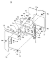
図1は、本発明の実施例1における防振装置100の分解斜視図である。実施例1の防振装置100は、光軸OAの方向に沿って第1の固定部材31、ボール51、可動部材41、駆動ユニット33、FPC35、第2の固定部材32から構成されている。すなわち、実施例1の防振装置100は、第1の固定部材31と第2の固定部材32によって可動部材41が挟まれた構成となっている。
(Example 1)
FIG. 1 is an exploded perspective view of the vibration isolator 100 according to the first embodiment of the present invention. The vibration isolator 100 of the first embodiment is composed of a first fixing member 31, a ball 51, a movable member 41, a drive unit 33, an FPC 35, and a second fixing member 32 along the direction of the optical axis OA. That is, the vibration isolator 100 of the first embodiment has a configuration in which the movable member 41 is sandwiched between the first fixing member 31 and the second fixing member 32.

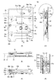
図2(A)は、防振装置100を光軸OAの方向に見た正面図、図2(B)は同底面図である。図2(C)は図2(A)の断面線IIC−IICにおける断面図、図2(D)は図2(A)の断面線IID−IIDにおける断面図、図2(E)は図2(C)の断面図における円で囲まれた駆動ユニット33a付近の拡大図である。 FIG. 2A is a front view of the vibration isolator 100 as viewed in the direction of the optical axis OA, and FIG. 2B is a bottom view of the same. 2 (C) is a sectional view taken along line IIC-IIC of FIG. 2 (A), FIG. 2 (D) is a sectional view taken along line IID-IID of FIG. 2 (A), and FIG. 2 (E) is FIG. It is an enlarged view around the drive unit 33a surrounded by a circle in the cross-sectional view of (C).

図2(A)において、3個の駆動ユニット33a、33b、33cがそれぞれ破線の矩形で示されるとともに、各駆動ユニット33a、33b、33cの発生する駆動力a、b、cがそれぞれ矢印で示されている。各穴34a、34b、34cは、第1の固定部材31を後述の撮像装置10の本体に固定するための穴である。FPC35は、駆動ユニット33に給電するためのフレキシブルプリント基板である。そして、締結部材であるネジ36a、36b、36cは、第1の固定部材31と第2の固定部材32を光軸OAの方向にスペーサ部材37a、37b、37cを介して連結し、締結する。なお、明細書における30番台の数字は、固定部(防振のための駆動に対して移動しない部材)に付されている。 In FIG. 2A, the three drive units 33a, 33b, 33c are indicated by dashed rectangles, and the driving forces a, b, c generated by the drive units 33a, 33b, 33c are indicated by arrows, respectively. Has been done. The holes 34a, 34b, and 34c are holes for fixing the first fixing member 31 to the main body of the image pickup apparatus 10 described later. The FPC 35 is a flexible printed board for supplying power to the drive unit 33. Then, the screws 36a, 36b, 36c, which are fastening members, connect the first fixing member 31 and the second fixing member 32 in the direction of the optical axis OA via the spacer members 37a, 37b, 37c and fasten them. The numbers in the 30s in the specification are attached to the fixed portion (a member that does not move with respect to the drive for vibration isolation).

防振装置100は、駆動ユニット33により適切な変位を発生させることにより、2方向の並進及び1軸周りの回転運動を可能としている。すなわち図2(A)の正面図の投影方向に直交する平面内の2方向の並進と、投影方向を回転軸とする1軸周りの回転運動が可能となっている。投影方向は光軸OAの方向であるので、可動部材41が光軸OAの方向に垂直な平面内で移動可能に支持されている。可動部材41には、撮像素子12を取り付けるためのネジ穴と位置決めピンを備えた素子固定部40a、40b、40cが光軸OAの方向に突出して備えられている。そして、後述の図5(B)で示されるブレ検知手段19の信号に基づいて、駆動ユニット33を適切に駆動させることで、手振れの影響を抑制し、撮像素子12における像を安定させることができる。 The vibration isolator 100 enables translation in two directions and rotational movement around one axis by generating an appropriate displacement by the drive unit 33. That is, translation in two directions in a plane orthogonal to the projection direction in the front view of FIG. 2A and rotational movement around one axis with the projection direction as the rotation axis are possible. Since the projection direction is the direction of the optical axis OA, the movable member 41 is movably supported in a plane perpendicular to the direction of the optical axis OA. The movable member 41 is provided with element fixing portions 40a, 40b, 40c provided with screw holes for attaching the image pickup element 12 and positioning pins so as to project in the direction of the optical axis OA. Then, by appropriately driving the drive unit 33 based on the signal of the blur detection means 19 shown in FIG. 5 (B) described later, the influence of camera shake can be suppressed and the image in the image sensor 12 can be stabilized. can.

可動部材41には基板42が取り付けられ、この基板42には実装された電子部品43が配置されている。電子部品43は、不図示のFPC(振動波アクチュエータに給電するFPC35とは異なるフレキシブルプリント基板)を介して、画像処理部13へ信号を伝送する。なお、明細書における40番台の数字は、可動部(防振のための駆動により移動する被駆動部材)に付されている。 A substrate 42 is attached to the movable member 41, and mounted electronic components 43 are arranged on the substrate 42. The electronic component 43 transmits a signal to the image processing unit 13 via an FPC (flexible printed board different from the FPC 35 that supplies power to the vibration wave actuator) (not shown). The numbers in the 40s in the specification are attached to the movable portion (the driven member that moves by driving for vibration isolation).

図2(E)を参照して、駆動ユニット33aの構成について説明する。駆動ユニット33aは、振動板52a及び圧電素子53aから構成される振動波アクチュエータと、振動波アクチュエータを加圧するバネ55aとフェルト54a、振動波アクチュエータにより駆動されるスライダ44aを有する。また、その他の駆動ユニット33b、33cについては、駆動ユニット33aと同様の構成であるため説明を省略する。なお、明細書における50番台の数字は、駆動部を構成する部材に付されている。 The configuration of the drive unit 33a will be described with reference to FIG. 2 (E). The drive unit 33a has a vibration wave actuator composed of a vibration plate 52a and a piezoelectric element 53a, a spring 55a and a felt 54a for pressurizing the vibration wave actuator, and a slider 44a driven by the vibration wave actuator. Further, since the other drive units 33b and 33c have the same configuration as the drive unit 33a, the description thereof will be omitted. The numbers in the 50s in the specification are attached to the members constituting the drive unit.

スライダ44aは、可動部材41に固定されるとともに、振動板52aに当接している。一方、バネ55aは第2の固定部材32に固定されており、フェルト54aはバネ55aの表面に固定されている。そして、FPC35を介して圧電素子53aに適宜電圧を印加することで、振動板52aが超音波領域の周波数の振動(超音波振動)を発生し、スライダ44aを駆動することにより可動部材41を移動させる。 The slider 44a is fixed to the movable member 41 and is in contact with the diaphragm 52a. On the other hand, the spring 55a is fixed to the second fixing member 32, and the felt 54a is fixed to the surface of the spring 55a. Then, by applying an appropriate voltage to the piezoelectric element 53a via the FPC 35, the diaphragm 52a generates vibration (ultrasonic vibration) at a frequency in the ultrasonic region, and drives the slider 44a to move the movable member 41. Let me.

第1の固定部材31とスライダ44aの間には、ボール51aが挟持され、振動板52aにより駆動されるスライダ44aが案内される。スライダ44aは、可動部材41に設けられているため、すなわちボール51aは第1の固定部材31と可動部材41に狭持されることになる。図2(E)に示すような構成とすることで、バネ55aの弾性力により振動波アクチュエータの振動板52aを所定の圧力をもってスライダ44aに当接させることができる。 A ball 51a is sandwiched between the first fixing member 31 and the slider 44a, and the slider 44a driven by the diaphragm 52a is guided. Since the slider 44a is provided on the movable member 41, that is, the ball 51a is sandwiched between the first fixing member 31 and the movable member 41. With the configuration as shown in FIG. 2E, the vibrating plate 52a of the vibration wave actuator can be brought into contact with the slider 44a with a predetermined pressure by the elastic force of the spring 55a.

図2(D)は、第1の固定部材31と第2の固定部材32とを連結する構成を示している。第1の固定部材31と第2の固定部材32は、円筒形状を成すスペーサ部材37bを介して連結されている。スペーサ部材37bの中央付近には、径が細くなった小径部があり、そこに弾性部材38bが嵌合している。ここでいう嵌合とは、取り付ける前の弾性部材38bの内径が、スペーサ部材37bの径よりも小さくなっている状態において、弾性部材38bが弾性変形してスペーサ部材37bに隙間なく取り付けられることを意味する。この弾性部材38bがいわゆるメカニカルストッパを形成している。このような構成により、外部から加えられた衝撃によって可動部材41が変位した時にも移動が規制される。 FIG. 2D shows a configuration in which the first fixing member 31 and the second fixing member 32 are connected to each other. The first fixing member 31 and the second fixing member 32 are connected via a spacer member 37b having a cylindrical shape. Near the center of the spacer member 37b, there is a small diameter portion having a reduced diameter, and the elastic member 38b is fitted therein. Fitting here means that the elastic member 38b is elastically deformed and attached to the spacer member 37b without a gap in a state where the inner diameter of the elastic member 38b before attachment is smaller than the diameter of the spacer member 37b. means. The elastic member 38b forms a so-called mechanical stopper. With such a configuration, movement is restricted even when the movable member 41 is displaced due to an impact applied from the outside.

スペーサ部材37bには、その長手方向の両端部にネジ穴39bが設けられており、長手方向の一端部において、ネジ36bにより第1の固定部材31が締結されている。スペーサ部材37bの他端部において、ネジ36bによりスペーサ部材37bと第2の固定部材32が締結されており、このようにスペーサ部材37bを介すことにより、第1の固定部材31と第2の固定部材32の間隔が保たれる。これらのネジ36bの締結により、駆動ユニット33のバネ55を弾性変形させて、振動板52をスライダ44に押圧させている。すなわち、第1の固定部材31に第2の固定部材32を固定することで、振動板52とスライダ44を所定の圧力をもって接触させる構成となっている。 The spacer member 37b is provided with screw holes 39b at both ends in the longitudinal direction, and the first fixing member 31 is fastened to the spacer member 37b by screws 36b at one end in the longitudinal direction. At the other end of the spacer member 37b, the spacer member 37b and the second fixing member 32 are fastened by a screw 36b, and by passing through the spacer member 37b in this way, the first fixing member 31 and the second fixing member 31 can be used. The spacing between the fixing members 32 is maintained. By fastening these screws 36b, the spring 55 of the drive unit 33 is elastically deformed, and the diaphragm 52 is pressed against the slider 44. That is, by fixing the second fixing member 32 to the first fixing member 31, the diaphragm 52 and the slider 44 are brought into contact with each other with a predetermined pressure.

図4(A)、(B)を参照して振動波アクチュエータの構成と動作について説明する。上述のように振動波アクチュエータは、振動板52と圧電素子53から構成されている。そして、圧電素子53には3つの電極61(A相)、62(B相)、63(GND)が形成されている。A相−GND間及びB相−GND間に、振動板52が共振を励起する周波数の電圧を印加するとともに、A相、B相への印加電圧に位相差を与えることで振動板52に形成された出力部52pを楕円運動させる。そして、振動板52の出力部52pが当接するスライダ44をこの楕円運動により変位させることができる。本発明では電磁的な作用を利用せずに、超音波の周波数領域での機械的な振動を直接取り出して駆動するものを振動波アクチュエータ(超音波アクチュエータ)と呼ぶ。上述した振動波アクチュエータの詳細な構成や動作に関しては、特開2016−92879号公報の開示を参照することとし、本発明の振動波アクチュエータの動作についての詳細な説明は割愛する。 The configuration and operation of the vibration wave actuator will be described with reference to FIGS. 4A and 4B. As described above, the vibration wave actuator is composed of the diaphragm 52 and the piezoelectric element 53. The piezoelectric element 53 is formed with three electrodes 61 (A phase), 62 (B phase), and 63 (GND). Formed on the diaphragm 52 by applying a voltage at a frequency at which the diaphragm 52 excites resonance between the A phase and GND and between the B phase and GND, and giving a phase difference to the applied voltages to the A phase and the B phase. The output unit 52p is made to move in an elliptical manner. Then, the slider 44 with which the output portion 52p of the diaphragm 52 abuts can be displaced by this elliptical motion. In the present invention, an actuator that directly extracts and drives mechanical vibration in the frequency range of ultrasonic waves without utilizing electromagnetic action is called a vibration wave actuator (ultrasonic actuator). Regarding the detailed configuration and operation of the vibration wave actuator described above, the disclosure of Japanese Patent Application Laid-Open No. 2016-92879 will be referred to, and the detailed description of the operation of the vibration wave actuator of the present invention will be omitted.

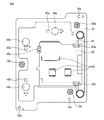
図3は、可動部材41に固定されたスライダ44よりも第2の固定部材32側に存在する部材を取り外した状態、すなわち第2の固定部材32、FPC35及び駆動ユニット33を取り外した状態の正面図である。図3に示すように、可動部材41には、スライダ44a、44b、44cの近傍にそれぞれ磁石45a、45b、45cが設けられている。そして、各磁石45a、45b、45cはFPC35と対向し、各磁石45a、45b、45cに対応するFPC35の位置には不図示の磁気センサ(ホール素子などが利用可能)が設けられている。 FIG. 3 shows the front surface of a state in which a member existing on the second fixing member 32 side of the slider 44 fixed to the movable member 41 is removed, that is, a state in which the second fixing member 32, the FPC 35, and the drive unit 33 are removed. It is a figure. As shown in FIG. 3, the movable member 41 is provided with magnets 45a, 45b, 45c in the vicinity of the sliders 44a, 44b, 44c, respectively. The magnets 45a, 45b, 45c face the FPC35, and a magnetic sensor (Hall element or the like) (not shown) is provided at the position of the FPC35 corresponding to the magnets 45a, 45b, 45c.

実施例1の防振装置100の制御においては、磁石45a、45b、45cと磁気センサによって可動部材41と第1の固定部材31との相対的な変位(相対移動)を検知して、この検知結果と目標値を比較する、いわゆるフィードバック制御が行われる。さらに、特定の方向に駆動する場合に、駆動に寄与しない方向の振動波アクチュエータも突き上げ方向の振動を励起させる(これは足踏み振動などとも呼ばれる)。一般的には、図4(A)のA相−GND間及びB相−GND間に同じ位相の電圧を印加することで突き上げ方向の振動を励起することができる。具体的には、可動部材41を図3の上下方向に移動させる場合には、駆動ユニット33aによって上下方向の駆動力aを発生させるとともに、他の駆動ユニット33b、33cには足踏み振動をさせる。さらに、フィードバック制御を行うことで、可動部材41が上下方向のみに移動する。 In the control of the vibration isolator 100 of the first embodiment, the relative displacement (relative movement) between the movable member 41 and the first fixing member 31 is detected by the magnets 45a, 45b, 45c and the magnetic sensor, and this detection is performed. So-called feedback control is performed to compare the result with the target value. Furthermore, when driving in a specific direction, a vibration wave actuator in a direction that does not contribute to driving also excites vibration in the push-up direction (this is also called stepping vibration). Generally, the vibration in the push-up direction can be excited by applying a voltage having the same phase between the A phase and the GND and between the B phase and the GND in FIG. 4 (A). Specifically, when the movable member 41 is moved in the vertical direction in FIG. 3, the drive unit 33a generates a drive force a in the vertical direction, and the other drive units 33b and 33c are caused to step on the vibration. Further, by performing feedback control, the movable member 41 moves only in the vertical direction.

図2(E)を参照すると、実施例1の防振装置100では、振動板52aがスライダ44aに当接する当接面の裏面が、ボール51aを案内する案内面となっている。表面硬度が求められるスライダ44において、振動板52が当接する当接面及びボール51を案内する案内面を同一部材の表裏に集約したことで、表面処理の工数を削減することができるとともに、このような構成とすることでコストを削減することができる。 Referring to FIG. 2E, in the vibration isolator 100 of the first embodiment, the back surface of the contact surface where the diaphragm 52a abuts on the slider 44a is a guide surface for guiding the ball 51a. In the slider 44 where the surface hardness is required, the contact surface with which the diaphragm 52 abuts and the guide surface for guiding the ball 51 are integrated on the front and back of the same member, so that the man-hours for surface treatment can be reduced and the surface treatment man-hours can be reduced. The cost can be reduced by adopting such a configuration.

図1〜図3に示すように、実施例1の防振装置100は、可動部材41が振動板52と複数のボール51に挟み込まれる構成をしている。このため、振動波アクチュエータに電圧を印加しない時にも摩擦力によって可動部材41が保持されるので、可動部材41を保持するためのロック機構が不要となり装置が大型化することが無い。したがって、大型化することなくガタ等の影響を低減した防振装置100を提供することができる。 As shown in FIGS. 1 to 3, the vibration isolator 100 of the first embodiment has a configuration in which the movable member 41 is sandwiched between the diaphragm 52 and a plurality of balls 51. Therefore, since the movable member 41 is held by the frictional force even when the voltage is not applied to the vibration wave actuator, the lock mechanism for holding the movable member 41 becomes unnecessary and the device does not become large. Therefore, it is possible to provide the vibration isolator 100 that reduces the influence of backlash and the like without increasing the size.

また、図2(A)〜(E)を参照すると、各駆動ユニット33a、33b、33cは、同じ構成で並列に設けられている。第2の固定部材32から各バネ55a、55b(不図示)、55c(不図示)、を介して振動板52a、52b(不図示)、52c(不図示)が並列に配置されて可動部材41のスライダ44a、44b(不図示)、44c(不図示)と当接している。すなわち、可動部材41と第2の固定部材32の間に並列に複数の振動波アクチュエータが設けられた構成となっている。特に複数の振動波アクチュエータの振動板52に設けられた出力部52pが、直接スライダ44に対して接触する構成となっている。このような構成とすることで、スライダ44を他の部材を介在させることなく駆動することができる。すなわち、ガタ等の影響を低減した防振装置100を提供することができる。 Further, referring to FIGS. 2A to 2E, the drive units 33a, 33b, 33c are provided in parallel with the same configuration. The diaphragms 52a, 52b (not shown) and 52c (not shown) are arranged in parallel from the second fixing member 32 via the springs 55a, 55b (not shown) and 55c (not shown), and the movable member 41 is arranged. In contact with the sliders 44a, 44b (not shown) and 44c (not shown). That is, a plurality of vibration wave actuators are provided in parallel between the movable member 41 and the second fixing member 32. In particular, the output unit 52p provided on the diaphragm 52 of the plurality of vibration wave actuators is configured to directly contact the slider 44. With such a configuration, the slider 44 can be driven without intervening other members. That is, it is possible to provide the vibration isolator 100 with less influence of backlash and the like.

第1の固定部材31には、防振装置100を撮像装置10の本体に固定するための穴34a、34b、34cが設けられ、特に穴34a、34bの近傍には、防振装置100を撮像装置10に固定する際の位置決めの穴が設けられている。このような構成とすることで、可動部材41の位置を正確に決定することができる。そして、振動波アクチュエータから撮像装置10への部材の配置は、振動波アクチュエータ→可動部材41→ボール51→第1の固定部材31→撮像装置10の順となっており、可動部材41を位置決めするために介在する部材が少ない。さらに、介在する部材のそれぞれが部品精度を高めやすい部材のみで構成されるため、可動部材41の位置を正確に決定することができる。このように、可動部材41(スライダ44)、ボール51、第1の固定部材31だけでフランジバック(FB)を決めることができるので、部材の積層方向(厚み方向)の不安定要素を排除することができる。すなわち、フェルト54や振動板52の劣化による影響を排除することができる。一般的には、撮像装置10のレンズ取付け部(レンズユニット20との機械的な境界部でマウントと呼ばれる)に対して防振装置100に設けられた撮像素子12の位置を正確に決める必要があるが、上述の構成をとることでこれが実現される。 The first fixing member 31 is provided with holes 34a, 34b, 34c for fixing the vibration isolator 100 to the main body of the image pickup device 10, and the vibration isolation device 100 is imaged particularly in the vicinity of the holes 34a, 34b. A positioning hole for fixing to the device 10 is provided. With such a configuration, the position of the movable member 41 can be accurately determined. The arrangement of the members from the vibration wave actuator to the image pickup device 10 is in the order of vibration wave actuator → movable member 41 → ball 51 → first fixing member 31 → image pickup device 10, and positions the movable member 41. Therefore, there are few intervening members. Further, since each of the intervening members is composed of only the members whose component accuracy can be easily improved, the position of the movable member 41 can be accurately determined. In this way, since the flange back (FB) can be determined only by the movable member 41 (slider 44), the ball 51, and the first fixing member 31, the unstable element in the stacking direction (thickness direction) of the members is eliminated. be able to. That is, the influence of deterioration of the felt 54 and the diaphragm 52 can be eliminated. Generally, it is necessary to accurately determine the position of the image sensor 12 provided in the vibration isolator 100 with respect to the lens mounting portion of the image pickup device 10 (called a mount at the mechanical boundary with the lens unit 20). However, this can be achieved by adopting the above configuration.

(適用例1)
図5(A)は、本発明の実施例1の防振装置100を備えた撮像装置10及びレンズユニット20からなるカメラシステム(光学装置)の断面図、図5(B)はカメラシステムの電気的構成を示すブロック図である。カメラシステムは、撮像手段、画像処理手段、記録再生手段及び制御手段を有する。撮像手段は、撮影光学系21、シャッタ機構18、撮像素子12を含み、画像処理手段は、画像処理部13を含む。また、記録再生手段は、メモリ手段14、表示手段15(表示手段15は背面表示装置15a、EVF15bを含む)を含む。制御手段は、カメラシステム制御回路11、操作検出部16、ブレ検知手段19、防振装置100、レンズシステム制御回路22及びレンズ駆動手段23を含む。レンズ駆動手段23は、フォーカスレンズ(撮影光学系21の一部のレンズ)、絞りなどを駆動する。
(Application example 1)
5 (A) is a cross-sectional view of a camera system (optical device) including an image pickup device 10 and a lens unit 20 provided with the vibration isolator 100 according to the first embodiment of the present invention, and FIG. 5 (B) is an electric circuit of the camera system. It is a block diagram which shows the structural structure. The camera system includes an image pickup means, an image processing means, a recording / reproducing means, and a control means. The image pickup means includes a photographing optical system 21, a shutter mechanism 18, and an image pickup element 12, and the image processing means includes an image processing unit 13. Further, the recording / reproducing means includes a memory means 14 and a display means 15 (the display means 15 includes a rear display device 15a and an EVF 15b). The control means include a camera system control circuit 11, an operation detection unit 16, a blur detection means 19, a vibration isolator 100, a lens system control circuit 22, and a lens driving means 23. The lens driving means 23 drives a focus lens (a part of the lens of the photographing optical system 21), an aperture, and the like.

撮像手段は、物体からの光を、撮影光学系21を介して撮像素子12の撮像面に結像する光学処理系である。撮影光学系21を介して物体の像が結ぶ面を結像面と呼び、撮像素子12は結像面に配置されている。撮像素子12からピント評価量/適当な露光量の信号が得られるので、この信号に基づいて適切に撮影光学系21が調整されることで、適切な光量の物体光を撮像素子12に露光するとともに、撮像素子12近傍で被写体像が結像する。 The image pickup means is an optical processing system that forms an image of light from an object on the image pickup surface of the image pickup element 12 via the photographing optical system 21. The surface formed by the images of the objects via the photographing optical system 21 is called an image forming surface, and the image pickup element 12 is arranged on the image forming surface. Since a signal of focus evaluation amount / appropriate exposure amount is obtained from the image sensor 12, the photographing optical system 21 is appropriately adjusted based on this signal to expose the image sensor 12 with an object light of an appropriate amount of light. At the same time, a subject image is formed in the vicinity of the image sensor 12.

画像処理部13は、内部にA/D変換器、ホワイトバランス調整回路、ガンマ補正回路、補間演算回路等を有しており、記録用の画像を生成することができる。色補間処理手段はこの画像処理部13に備えられており、ベイヤ配列の信号から色補間(デモザイキング)処理を施してカラー画像を生成する。また、画像処理部13は、予め定められた方法を用いて画像、動画、音声などの圧縮を行う。 The image processing unit 13 has an A / D converter, a white balance adjustment circuit, a gamma correction circuit, an interpolation calculation circuit, and the like inside, and can generate an image for recording. The color interpolation processing unit 13 is provided in the image processing unit 13, and performs color interpolation (demosiking) processing from the signals of the bayer array to generate a color image. Further, the image processing unit 13 compresses an image, a moving image, an audio, or the like by using a predetermined method.

メモリ手段14は実際の記憶部を備えている。カメラシステム制御回路11により、メモリ手段14の記録部へ出力を行うとともに、表示手段15にユーザに提示する像を表示(再生)する。 The memory means 14 includes an actual storage unit. The camera system control circuit 11 outputs to the recording unit of the memory means 14, and displays (reproduces) an image presented to the user on the display means 15.

カメラシステム制御回路11は撮像の際のタイミング信号などを生成して出力する。外部操作に応動して撮像手段、画像処理手段、記録再生手段をそれぞれ制御する。例えば、不図示のシャッターレリーズ釦の押下を操作検出部16が検出して、撮像素子12の駆動、画像処理部13の動作、圧縮処理などを制御する。さらに表示手段15によって情報表示を行う情報表示装置の各セグメントの状態を制御する。また、背面表示装置15aはタッチパネルになっており、操作検出部16に接続されている。 The camera system control circuit 11 generates and outputs a timing signal or the like at the time of imaging. The imaging means, the image processing means, and the recording / reproducing means are controlled in response to an external operation. For example, the operation detection unit 16 detects the pressing of the shutter release button (not shown) to control the drive of the image pickup device 12, the operation of the image processing unit 13, compression processing, and the like. Further, the display means 15 controls the state of each segment of the information display device that displays information. Further, the rear display device 15a is a touch panel and is connected to the operation detection unit 16.

撮影光学系21の調整動作について説明する。カメラシステム制御回路11には画像処理部13が接続されており、撮像素子12からの信号を元に適切な焦点位置、絞り位置を求める。カメラシステム制御回路11は、電気接点17を介してレンズシステム制御回路22に指令を出し、レンズシステム制御回路22はレンズ駆動手段23を適切に制御する。 The adjustment operation of the photographing optical system 21 will be described. An image processing unit 13 is connected to the camera system control circuit 11, and an appropriate focal position and aperture position are obtained based on the signal from the image sensor 12. The camera system control circuit 11 issues a command to the lens system control circuit 22 via the electric contact 17, and the lens system control circuit 22 appropriately controls the lens driving means 23.

撮像装置10は、シャッタ機構18を備えており、カメラシステム制御回路11からの指令により露光制御することが可能である。また、撮像装置10はブレ検知手段19及び防振装置100を備えており、いわゆる手振れの影響を低減することができる。すなわち、手振れ補正を行う際は、ブレ検知手段19(一例としてはジャイロセンサ)から得られた信号に基づいて、防振装置100に備えられた撮像素子12を変位させることで、手振れ補正を行い、手振れの影響を低減した撮影を行うことができる。 The image pickup apparatus 10 includes a shutter mechanism 18, and can control exposure by a command from the camera system control circuit 11. Further, the image pickup apparatus 10 is provided with the blur detection means 19 and the vibration isolator 100, and can reduce the influence of so-called camera shake. That is, when performing image stabilization, the image sensor 12 provided in the vibration isolator 100 is displaced based on the signal obtained from the image stabilization means 19 (for example, a gyro sensor) to perform image stabilization. , It is possible to take pictures with the influence of camera shake reduced.

広義の意味での防振装置は、ブレ検知手段19、制御を司るカメラシステム制御回路11、及び防振のための機構である防振装置100から成るが、本発明では特に構成に特徴があるので、防振のための構成を指す用語として防振装置という言葉を用いる。 The anti-vibration device in a broad sense includes a blur detection means 19, a camera system control circuit 11 that controls control, and an anti-vibration device 100 that is a mechanism for anti-vibration, but the present invention is particularly characterized in its configuration. Therefore, the term anti-vibration device is used as a term to refer to the configuration for anti-vibration.

(実施例2)
図6は、本発明の実施例2における防振装置200の分解斜視図である。実施例2の防振装置200は、光軸OAの方向に沿って第1の固定部材231、ボール251、アンチロールプレート281、ボール251、案内板246、可動部材241、駆動ユニット233、FPC235、第2の固定部材232から構成されている。実施例1と同様、実施例2の防振装置200は第1の固定部材231と第2の固定部材232によって可動部材241が挟まれた構成となっている。実施例2では、樹脂の成形品である樹脂部材231Bと金属板231Aの2つの部材から第1の固定部材231が構成されている。樹脂部材231Bと金属板231Aをまとめて扱う場合、第1の固定部材231と表すことにする。
(Example 2)
FIG. 6 is an exploded perspective view of the vibration isolator 200 according to the second embodiment of the present invention. The vibration isolator 200 of the second embodiment has a first fixing member 231, a ball 251 and an anti-roll plate 281 and a ball 251 along the direction of the optical axis OA, a guide plate 246, a movable member 241, a drive unit 233, and an FPC 235. It is composed of a second fixing member 232. Similar to the first embodiment, the vibration isolator 200 of the second embodiment has a configuration in which the movable member 241 is sandwiched between the first fixing member 231 and the second fixing member 232. In the second embodiment, the first fixing member 231 is composed of two members, a resin member 231B and a metal plate 231A, which are molded products of the resin. When the resin member 231B and the metal plate 231A are handled together, they are referred to as the first fixing member 231.

実施例2の説明において、実施例1と同じ機能を持つ部材には、200を加えた番号が付されている。なお、実施例1では防振において変位させる対象が光学素子である撮像素子12であるが、実施例2では撮像という機能の点で異なるものの、防振において変位させるという点で同一でもある光学部材(光学素子)のレンズに対して防振レンズ212を付している。 In the description of the second embodiment, the members having the same function as that of the first embodiment are numbered by adding 200. In the first embodiment, the object to be displaced in the vibration isolation is the image pickup element 12, which is an optical element. However, in the second embodiment, the optical member is the same in that it is displaced in the vibration isolation, although it differs in the function of imaging. A vibration-proof lens 212 is attached to the lens (optical element).

図7(A)は、防振装置200を光軸OAの方向にみた正面図、図7(B)は同底面図である。図7(C)は図7(A)の断面線VIIC−VIICにおける断面図、図7(D)は図7(A)の断面線VIID−VIIDにおける断面図である。 7 (A) is a front view of the vibration isolator 200 as viewed in the direction of the optical axis OA, and FIG. 7 (B) is a bottom view of the same. 7 (C) is a sectional view taken along line VIIC-VIIC of FIG. 7 (A), and FIG. 7 (D) is a sectional view taken along line VIID-VIID of FIG. 7 (A).

図7(A)において、2個の駆動ユニット233a、233bがそれぞれ破線の矩形で示されるとともに、各駆動ユニット233a、233bの発生する駆動力a、bがそれぞれ矢印で示されている。図7(B)において、樹脂部材231Bが備える穴234aは、第1の固定部材231を後述の撮影光学系21の本体に固定するための穴である。図7(B)では、穴234aが1つしか示されていないが、さらに他の穴が円周方向に120度等分で2か所に設けられている。FPC235a、235bは、駆動ユニット233a、233bに給電するためのフレキシブルプリント基板である。そして、締結部材であるネジ236a、236b、236cは、第1の固定部材231をなす金属板231Aと第2の固定部材232を光軸OAの方向に連結し、締結する。 In FIG. 7A, the two drive units 233a and 233b are indicated by dashed rectangles, and the driving forces a and b generated by the drive units 233a and 233b are indicated by arrows, respectively. In FIG. 7B, the hole 234a provided in the resin member 231B is a hole for fixing the first fixing member 231 to the main body of the photographing optical system 21 described later. In FIG. 7B, only one hole 234a is shown, but another hole is provided in two places evenly divided by 120 degrees in the circumferential direction. The FPC 235a and 235b are flexible printed boards for supplying power to the drive units 233a and 233b. Then, the screws 236a, 236b, and 236c, which are fastening members, connect the metal plate 231A forming the first fixing member 231 and the second fixing member 232 in the direction of the optical axis OA and fasten them.

防振装置200は、駆動ユニット233により適切な変位を発生させることにより、2方向の並進運動を可能としている。すなわち実施例2の防振装置200と実施例1の防振装置100との機構の違いは、防振レンズ212を駆動する防振装置200において、回転が不要な2自由度であるので、光軸OAに垂直な平面内での並進運動のみを行うことである。回転運動を規制するための構成については後述する。 The vibration isolator 200 enables translational motion in two directions by generating an appropriate displacement by the drive unit 233. That is, the difference in mechanism between the anti-vibration device 200 of the second embodiment and the anti-vibration device 100 of the first embodiment is that the anti-vibration device 200 for driving the anti-vibration lens 212 has two degrees of freedom that do not require rotation. Only the translational motion in the plane perpendicular to the axis OA is performed. The configuration for regulating rotational motion will be described later.

可動部材241には、2つの発光素子245a、245bが備えられている。そして、図7(C)を参照すると、組み立て後に発光素子245a、245bとそれぞれ対向するように位置検出センサ272a、272b(不図示)が第2の固定部材232に固定された制御基板270に設けられている。位置検出センサ272a、272bには1次元PSD等を用いることができる。これにより可動部材241の位置を検出して、いわゆるフィードバック制御を行うことができる。なお、制御基板270にはコネクタ271が実装されている。 The movable member 241 is provided with two light emitting elements 245a and 245b. Then, referring to FIG. 7C, the position detection sensors 272a and 272b (not shown) are provided on the control board 270 fixed to the second fixing member 232 so as to face the light emitting elements 245a and 245b after assembly. Has been done. One-dimensional PSD or the like can be used for the position detection sensors 272a and 272b. As a result, the position of the movable member 241 can be detected and so-called feedback control can be performed. The connector 271 is mounted on the control board 270.

図7(C)を参照して、駆動ユニット233aの構成について説明する。実施例2の駆動ユニット233aは、実施例1とほぼ同等な構成である。駆動ユニット233aは、振動板252a及び圧電素子253aから構成される振動波アクチュエータと、振動波アクチュエータを加圧するバネ255aとフェルト254a、振動波アクチュエータにより駆動されるスライダ部244aを有する。実施例2の可動部材241は、スライダ機能を兼ねている。 The configuration of the drive unit 233a will be described with reference to FIG. 7 (C). The drive unit 233a of the second embodiment has almost the same configuration as that of the first embodiment. The drive unit 233a has a vibration wave actuator composed of a vibrating plate 252a and a piezoelectric element 253a, a spring 255a and felt 254a for pressurizing the vibration wave actuator, and a slider portion 244a driven by the vibration wave actuator. The movable member 241 of the second embodiment also has a slider function.

スライダ部244aは、可動部材241に一体化されるとともに、振動板252aに当接している。一方、バネ255aは第2の固定部材232に固定されており、フェルト254aはバネ255aの表面に固定されている。そして、FPC235aを介して圧電素子253aに適宜電圧を印加することで、振動板252aが超音波領域の周波数の振動(超音波振動)を発生し、スライダ部244aを駆動することにより可動部材241を移動させる。 The slider portion 244a is integrated with the movable member 241 and is in contact with the diaphragm 252a. On the other hand, the spring 255a is fixed to the second fixing member 232, and the felt 254a is fixed to the surface of the spring 255a. Then, by appropriately applying a voltage to the piezoelectric element 253a via the FPC 235a, the diaphragm 252a generates vibration (ultrasonic vibration) at a frequency in the ultrasonic region, and drives the slider portion 244a to drive the movable member 241. Move it.

第1の固定部材231と可動部材241の間には、6つのボール251a、251b、251c、251d、251e、251fが挟持され、振動板252aにより駆動されるスライダ部244aが案内される。図7(C)に示すような構成とすることで、バネ255aの弾性力により振動波アクチュエータの振動板252aを所定の圧力をもってスライダ部244aに当接させることができる。なお、FPC235aは制御基板270に接続されている。 Six balls 251a, 251b, 251c, 251d, 251e, and 251f are sandwiched between the first fixing member 231 and the movable member 241 to guide the slider portion 244a driven by the diaphragm 252a. With the configuration as shown in FIG. 7C, the vibrating plate 252a of the vibration wave actuator can be brought into contact with the slider portion 244a with a predetermined pressure by the elastic force of the spring 255a. The FPC 235a is connected to the control board 270.

図6を参照して実施例2の防振装置200が有する各ボールについて説明する。ボール251aは、可動部材241の平面部と第1の固定部材231をなす金属板231Aの平面部に挟持されており、ボール251bはアンチロールプレート281の平面部と樹脂部材231Bに挟持されている。ボール251c、251dは可動部材241に固定された案内板246とアンチロールプレート281に挟持されており、ボール251e、251fはアンチロールプレート281と第1の固定部材231をなす金属板231Aに挟持されている。 Each ball included in the vibration isolator 200 of the second embodiment will be described with reference to FIG. The ball 251a is sandwiched between the flat surface portion of the movable member 241 and the flat surface portion of the metal plate 231A forming the first fixing member 231. The ball 251b is sandwiched between the flat surface portion of the anti-roll plate 281 and the resin member 231B. .. The balls 251c and 251d are sandwiched between the guide plate 246 fixed to the movable member 241 and the anti-roll plate 281, and the balls 251e and 251f are sandwiched between the metal plate 231A forming the anti-roll plate 281 and the first fixing member 231. ing.

図8(A)は、第2の固定部材232、FPC235及び駆動ユニット233を取り外した状態の正面図、図8(B)は図8(A)の断面線VIIIB−VIIIBにおける断面図である。図8(A)に示すように、可動部材241には、発光素子245a、245bが設けられている。図7(C)を参照すると、発光素子245aは、位置検出センサ272aと対向するように配置されており、可動部材241の上下方向の変位を検出する。 8 (A) is a front view showing a state in which the second fixing member 232, FPC 235 and the drive unit 233 are removed, and FIG. 8 (B) is a cross-sectional view taken along the cross-sectional line VIIIB-VIIIB of FIG. 8 (A). As shown in FIG. 8A, the movable member 241 is provided with light emitting elements 245a and 245b. Referring to FIG. 7C, the light emitting element 245a is arranged so as to face the position detection sensor 272a, and detects the vertical displacement of the movable member 241.

図6、図7(C)を参照すると、実施例2の防振装置200では、振動板252a、252bがスライダ部244a、244bに当接する当接面とボール251aが可動部材241に案内される案内面とを離間させた構成となっている。すなわち、振動板252がスライダ部244に当接する当接面の裏面は、ボール251を案内する案内面になっていない。 Referring to FIGS. 6 and 7 (C), in the vibration isolator 200 of the second embodiment, the contact surface where the diaphragms 252a and 252b abut on the slider portions 244a and 244b and the ball 251a are guided to the movable member 241. It is configured to be separated from the guide surface. That is, the back surface of the contact surface where the diaphragm 252 abuts on the slider portion 244 is not a guide surface for guiding the ball 251.

実施例2の防振装置200において、振動波アクチュエータの振動(特に案内方向ではなく、光軸OAの方向に突き上げるような振動)が課題になるような場合がある。このような場合、可動部材241において、振動板252が当接する当接面及びボール251を案内する案内面を光軸OAの方向から見たときに互いに重ならないようにしたことで、不要な振動を抑制することができる。 In the vibration isolator 200 of the second embodiment, the vibration of the vibration wave actuator (vibration that pushes up in the direction of the optical axis OA, not in the guiding direction) may become a problem. In such a case, unnecessary vibration is caused by preventing the movable member 241 from overlapping the contact surface with which the diaphragm 252 abuts and the guide surface for guiding the ball 251 when viewed from the direction of the optical axis OA. Can be suppressed.

図6に示すように、実施例2の防振装置200は、可動部材241が振動板252と複数のボール251に挟み込まれる構成をしている。このため、振動波アクチュエータに電圧を印加しない時にも摩擦力によって可動部材241が保持されるので、可動部材241を保持するためのロック機構が不要となり装置が大型化することが無い。したがって、大型化することなくガタ等の影響を低減した防振装置200を提供することができる。 As shown in FIG. 6, the vibration isolator 200 of the second embodiment has a configuration in which the movable member 241 is sandwiched between the diaphragm 252 and a plurality of balls 251. Therefore, since the movable member 241 is held by the frictional force even when the voltage is not applied to the vibration wave actuator, the lock mechanism for holding the movable member 241 becomes unnecessary and the device does not become large. Therefore, it is possible to provide the vibration isolator 200 in which the influence of backlash and the like is reduced without increasing the size.

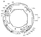
図9は、図8(A)に対してさらに可動部材241を取り外した状態の正面図、図10はさらにアンチロールプレート281を取り外した状態の正面図である。図6、図9及び図10を用いて、光軸OAに垂直な平面内での並進運動の案内構成について説明する。本発明の実施例2の防振装置200は、可動部材241に固定された案内板246及び可動部材241の光軸OA周りの回転を抑制するアンチロールプレート281を備えている。 9 is a front view of FIG. 8A with the movable member 241 removed, and FIG. 10 is a front view of the anti-roll plate 281 with the anti-roll plate 281 removed. A guide configuration for translational motion in a plane perpendicular to the optical axis OA will be described with reference to FIGS. 6, 9 and 10. The vibration isolator 200 of the second embodiment of the present invention includes a guide plate 246 fixed to the movable member 241 and an anti-roll plate 281 that suppresses the rotation of the movable member 241 around the optical axis OA.

案内板246は、2つのV溝247c、247dを備えるとともに、固定用のネジ248a、248bによって可動部材241に固定されている。さらに、案内板246に対向する位置にあるアンチロールプレート281は、図9の上下方向に延在する長穴282a、282bを備えている。そして、アンチロールプレート281は第1の固定部材231をなす金属板231Aに長穴282a、282bを介してピン283a、283bによって図面の上下方向にアンチロールプレート281の移動が許容される状態で光軸OAの方向に固定されている。また、アンチロールプレート281は、4つのV溝284c、284d、284e、284fを備えている。そして、第1の固定部材をなす金属板231Aは、2つのV溝230e、230fを備えている。 The guide plate 246 includes two V-grooves 247c and 247d, and is fixed to the movable member 241 by fixing screws 248a and 248b. Further, the anti-roll plate 281 located at a position facing the guide plate 246 includes elongated holes 282a and 282b extending in the vertical direction in FIG. 9. Then, the anti-roll plate 281 is optical in a state where the anti-roll plate 281 is allowed to move in the vertical direction of the drawing by the pins 283a and 283b via the elongated holes 282a and 282b in the metal plate 231A forming the first fixing member 231. It is fixed in the direction of the axis OA. Further, the anti-roll plate 281 is provided with four V-grooves 284c, 284d, 284e and 284f. The metal plate 231A forming the first fixing member includes two V-grooves 230e and 230f.

アンチロールプレート281の2つのV溝284c、284dは、案内板246の2つのV溝247c、247dに対応して延在している。そして、ボール251cがV溝247cとV溝284cとにより、ボール251dがV溝247dとV溝284dとによりそれぞれ狭持されている。また、アンチロールプレート281の2つのV溝284e、284fは、金属板231Aの2つのV溝230e、230fに対応して延在している。そして、ボール251eがV溝284eとV溝230eとにより、ボール251fがV溝284fとV溝230fとによりそれぞれ狭持されている。 The two V-grooves 284c and 284d of the anti-roll plate 281 extend corresponding to the two V-grooves 247c and 247d of the guide plate 246. The ball 251c is sandwiched by the V-groove 247c and the V-groove 284c, and the ball 251d is sandwiched by the V-groove 247d and the V-groove 284d, respectively. Further, the two V-grooves 284e and 284f of the anti-roll plate 281 extend corresponding to the two V-grooves 230e and 230f of the metal plate 231A. The ball 251e is sandwiched by the V-groove 284e and the V-groove 230e, and the ball 251f is sandwiched by the V-groove 284f and the V-groove 230f, respectively.

ボール251c、251dを一組として同じ方向に案内するために、アンチロールプレート281の一方の平面部において、V溝284c、284dが図9の左右方向に揃えて設けられている。また、図6に示すように、案内板246においてV溝247c、247dが同じ方向に揃えて設けられている。さらに、ボール251e及び251fを一組として同じ方向に案内するために、アンチロールプレート281の一方の平面部の反対側の平面部において、V溝284e、284fが図9の上下方向に揃えて設けられている。また、図10に示すように、第1の固定部材231をなす金属板231Aの表面においてV溝230e、230fが図面の上下方向に揃えて設けられている。 In order to guide the balls 251c and 251d in the same direction as a set, V grooves 284c and 284d are provided in one flat surface portion of the anti-roll plate 281 so as to be aligned in the left-right direction in FIG. Further, as shown in FIG. 6, V grooves 247c and 247d are provided in the guide plate 246 so as to be aligned in the same direction. Further, in order to guide the balls 251e and 251f in the same direction as a set, V grooves 284e and 284f are provided in the vertical direction of FIG. 9 in the flat surface portion on the opposite side of one flat surface portion of the anti-roll plate 281. Has been done. Further, as shown in FIG. 10, V grooves 230e and 230f are provided on the surface of the metal plate 231A forming the first fixing member 231 so as to be aligned in the vertical direction of the drawing.

このような構成とすることで、第1の固定部材231をなす金属板231Aに対してアンチロールプレート281は上下方向にのみ、またアンチロールプレート281に対して可動部材241は左右方向にのみ並進できるように案内される。結果として、第1の固定部材231をなす金属板231Aに対して可動部材241は、光軸OAに垂直な平面内での並進運動のみ可能で回転運動は規制されることになる。なお、ボール251bは荷重のバランスをとるために設けられており、方向を規制しない。これらの構成は、特開2011−158924号公報に開示されているため、ここではこれ以上詳述しない。 With such a configuration, the anti-roll plate 281 translates only in the vertical direction with respect to the metal plate 231A forming the first fixing member 231 and the movable member 241 translates only in the horizontal direction with respect to the anti-roll plate 281. You will be guided so that you can. As a result, the movable member 241 can only move in translation in a plane perpendicular to the optical axis OA with respect to the metal plate 231A forming the first fixing member 231, and the rotational movement is restricted. The ball 251b is provided to balance the load and does not regulate the direction. Since these configurations are disclosed in Japanese Patent Application Laid-Open No. 2011-158924, they will not be described in detail here.

図7(A)において示した駆動ユニット233a、233bが駆動力a、bを発生すると、図9で説明した案内構成によって可動部材241が光軸OAに垂直な平面内で駆動される。また、各駆動ユニット233a、233bは、同じ構成で並列に設けられている。第2の固定部材232から各バネ255a、255b(不図示)、を介して振動板252a、252b(不図示)が並列に配置されて可動部材241のスライダ部244a、244b(不図示)と当接している。すなわち、可動部材241と第2の固定部材232の間に並列に複数の振動波アクチュエータが設けられた構成となっている。特に複数の振動波アクチュエータの振動板252に設けられた出力部252p(不図示)が、直接可動部材241に対して接触する構成となっている。このような構成とすることで、スライダ部244を他の部材を介在させることなく駆動することができる。すなわち、ガタ等の影響を低減した防振装置200を提供することができる。 When the drive units 233a and 233b shown in FIG. 7A generate driving forces a and b, the movable member 241 is driven in a plane perpendicular to the optical axis OA by the guide configuration described with reference to FIG. Further, the drive units 233a and 233b are provided in parallel with the same configuration. The diaphragms 252a and 252b (not shown) are arranged in parallel from the second fixing member 232 via the springs 255a and 255b (not shown), and are in contact with the slider portions 244a and 244b (not shown) of the movable member 241. I'm in contact. That is, a plurality of vibration wave actuators are provided in parallel between the movable member 241 and the second fixing member 232. In particular, the output unit 252p (not shown) provided on the diaphragms 252 of the plurality of vibration wave actuators is configured to directly contact the movable member 241. With such a configuration, the slider portion 244 can be driven without interposing other members. That is, it is possible to provide the vibration isolator 200 in which the influence of backlash and the like is reduced.

第1の固定部材231をなす樹脂部材231Bには、防振装置200をレンズユニット20の本体に固定するための穴234a、234b(不図示)、234c(不図示)が設けられている。このような構成とすることで、可動部材241の位置を正確に決定することができる。そして、振動波アクチュエータからレンズユニット20への部材の配置は、振動波アクチュエータ→可動部材241→ボール251a→金属板231A→樹脂部材231B→撮像装置10の順となっている。もしくは振動波アクチュエータ→可動部材241→案内板246→ボール251c、251d→アンチロールプレート281→ボール251e、251f→金属板231A→樹脂部材231B→撮像装置10の順となっている。このように可動部材241を位置決めするために介在する部材が少ない。さらに、介在する部材のそれぞれが部品精度を高めやすい部材のみで構成されるため、可動部材241の位置を精密に決定することができる。上述の後段の配置の順は、経路が一見長いように見えるが、単純な平板部材と転動部材であるので部品精度を高めやすい。一般的には、レンズユニット20の撮像装置10への取付け部(撮像装置10との機械的な境界部でマウントと呼ばれる)に対して防振装置200に設けられた防振レンズ212の位置を正確に決める必要があるが、上述の構成によりこれが実現される。 The resin member 231B forming the first fixing member 231 is provided with holes 234a and 234b (not shown) and 234c (not shown) for fixing the vibration isolator 200 to the main body of the lens unit 20. With such a configuration, the position of the movable member 241 can be accurately determined. The arrangement of the members from the vibration wave actuator to the lens unit 20 is in the order of vibration wave actuator → movable member 241 → ball 251a → metal plate 231A → resin member 231B → image pickup device 10. Alternatively, the order is vibration wave actuator → movable member 241 → guide plate 246 → ball 251c, 251d → anti-roll plate 281 → ball 251e, 251f → metal plate 231A → resin member 231B → image pickup device 10. As described above, there are few members intervening to position the movable member 241. Further, since each of the intervening members is composed of only the members whose component accuracy can be easily improved, the position of the movable member 241 can be accurately determined. In the order of arrangement in the latter stage described above, the path seems to be long at first glance, but since it is a simple flat plate member and a rolling member, it is easy to improve the accuracy of parts. Generally, the position of the anti-vibration lens 212 provided in the anti-vibration device 200 is set with respect to the attachment portion of the lens unit 20 to the image pickup device 10 (called a mount at the mechanical boundary portion with the image pickup device 10). This needs to be determined accurately, but this is achieved by the above configuration.

(適用例2)
図11(A)は、本発明の実施例2の防振装置200を備えたレンズユニット20及び撮像装置10からなるカメラシステム(光学装置)の断面図、図11(B)はカメラシステムの電気的構成を示すブロック図である。図11(A)、(B)において図5(A)、(B)と同じ機能のものには同じ番号が付けられている。レンズシステム制御回路22は、ブレ検知手段29の信号に基づいて、防振装置200に備えられた光学素子である防振レンズ212を移動させることで、撮像素子12の像を安定させて手振れの影響を抑制することができる。手ぶれ補正を行う際には、撮像素子12から得られた信号を基にレンズシステム制御回路22を介して光学素子である防振レンズ212を適切にフィードバック制御する。その他の構成は、図5(A)、(B)と同様なので説明を割愛する。
(Application example 2)
11 (A) is a cross-sectional view of a camera system (optical device) including a lens unit 20 provided with the vibration isolator 200 of the second embodiment of the present invention and an image pickup device 10, and FIG. 11 (B) is an electric circuit of the camera system. It is a block diagram which shows the structural structure. In FIGS. 11A and 11B, those having the same functions as those in FIGS. 5A and 5B are numbered the same. The lens system control circuit 22 stabilizes the image of the image pickup element 12 and causes camera shake by moving the anti-vibration lens 212, which is an optical element provided in the anti-vibration device 200, based on the signal of the blur detection means 29. The effect can be suppressed. When performing image stabilization, the anti-vibration lens 212, which is an optical element, is appropriately feedback-controlled via the lens system control circuit 22 based on the signal obtained from the image pickup element 12. Other configurations are the same as those in FIGS. 5A and 5B, so the description thereof will be omitted.

10 撮像装置
12 撮像素子(光学素子)
20 レンズユニット
31、231 第1の固定部材
32、232 第2の固定部材
41、241 可動部材
44、244 スライダ
51、251 ボール
52、252 振動板
53、253 圧電素子
55、255 バネ
212 防振レンズ(光学素子)
100、200 防振装置
OA 光軸
10 Image pickup device 12 Image pickup element (optical element)
20 Lens unit 31, 231 First fixing member 32, 232 Second fixing member 41, 241 Movable member 44, 244 Slider 51, 251 Ball 52, 252 Diaphragm 53, 253 Piezoelectric element 55, 255 Spring 212 Anti-vibration lens (Optical element)
100, 200 Anti-vibration device OA optical axis

Claims (12)

撮像素子と、
第1の固定部材と、
前記撮像素子を保持し、光軸に垂直な平面内で移動可能に支持される可動部材と、
前記可動部材と前記第1の固定部材とに挟持されたボールと、
圧電素子と振動板とを備え、前記可動部材を移動させる振動波アクチュエータと、
前記振動板に当接し、前記可動部材に設けられたスライダと、
前記振動板を前記スライダに加圧するバネと、
前記振動板と前記スライダとを所定の圧力をもって接触させるように前記第1の固定部材に固定される第2の固定部材と、を備え
前記光軸の方向において、被写体側から前記第2の固定部材、前記振動波アクチュエータ、前記可動部材、前記ボール、前記第1の固定部材の順に部材が配置されていて、
前記可動部材は、前記光軸の方向において前記第2の固定部材よりも前記撮像素子が被写体側に位置するように前記撮像素子を保持していることを特徴とする撮像装置
Image sensor and
The first fixing member and
A movable member that holds the image sensor and is movably supported in a plane perpendicular to the optical axis.
A ball sandwiched between the movable member and the first fixing member,
A vibration wave actuator equipped with a piezoelectric element and a diaphragm to move the movable member,
A slider that is in contact with the diaphragm and is provided on the movable member,
A spring that pressurizes the diaphragm against the slider,
A second fixing member, which is fixed to the first fixing member so as to bring the diaphragm and the slider into contact with each other with a predetermined pressure, is provided .
In the direction of the optical axis, the members are arranged in the order of the second fixing member, the vibration wave actuator, the movable member, the ball, and the first fixing member from the subject side.
The movable member is an image pickup device that holds the image pickup element so that the image pickup element is located closer to the subject than the second fixing member in the direction of the optical axis .
前記可動部材における前記ボールの案内面と前記振動板が前記スライダに当接する当接面とは、同一部材の表裏であることを特徴とする、請求項1に記載の撮像装置 The image pickup apparatus according to claim 1, wherein the guide surface of the ball and the contact surface of the movable member with which the diaphragm abuts on the slider are the front and back surfaces of the same member. 前記スライダは、前記可動部材に固定されている、又は前記可動部材の一部が前記スライダの機能を有することを特徴とする、請求項1又は2に記載の撮像装置The image pickup apparatus according to claim 1 or 2 , wherein the slider is fixed to the movable member, or a part of the movable member has the function of the slider. 前記第1の固定部材を介して本体と接続されることを特徴とする、請求項1からのいずれか1項に記載の撮像装置 The image pickup apparatus according to any one of claims 1 to 3 , wherein the image pickup apparatus is connected to the main body via the first fixing member. 前記振動波アクチュエータは、前記可動部材と前記第2の固定部材との間に並列に設けられていることを特徴とする、請求項1からのいずれか1項に記載の撮像装置 The image pickup apparatus according to any one of claims 1 to 4 , wherein the vibration wave actuator is provided in parallel between the movable member and the second fixing member. 前記撮像素子は、前記振動板と前記可動部材との相対移動によって前記光軸の方向に対して垂直な平面内で移動することを特徴とする、請求項1からのいずれか1項に記載の撮像装置The invention according to any one of claims 1 to 5 , wherein the image pickup element moves in a plane perpendicular to the direction of the optical axis due to relative movement between the diaphragm and the movable member. Image sensor . 前記振動板は、前記スライダと当接する出力部が1つ設けられていることを特徴とする請求項1から6のいずれか1項に記載の撮像装置。The image pickup apparatus according to any one of claims 1 to 6, wherein the diaphragm is provided with one output unit that comes into contact with the slider. 前記振動波アクチュエータは、超音波領域の周波数の振動を利用した超音波アクチュエータであることを特徴とする、請求項1からのいずれか1項に記載の撮像装置 The image pickup apparatus according to any one of claims 1 to 7 , wherein the vibration wave actuator is an ultrasonic actuator utilizing vibration of a frequency in an ultrasonic region. 固定部材と、
撮像素子と、
前記撮像素子を保持し、前記固定部材に対して移動可能な可動部材と、
圧電素子と振動板とを備えた複数の振動子と、
前記可動部材と前記固定部材との間に配置され、前記固定部材に対して前記可動部材を移動可能に支持する複数の支持部材と、を備えた撮像装置において、
複数の前記振動子の少なくとも1つを振動させることで、前記固定部材に対して前記可動部材を移動させ、
複数の前記振動子は、前記可動部材の移動方向と平行な平面にて並ぶように配置され、
複数の前記支持部材は、前記可動部材における複数の前記振動子に対応する側とは反対側の面と前記固定部材との間に配置され
前記可動部材は、光軸の方向において前記振動子よりも前記撮像素子が被写体側に位置するように前記撮像素子を保持していることを特徴とする撮像装置
With fixing members
Image sensor and
A movable member that holds the image sensor and is movable with respect to the fixed member,
Multiple oscillators with piezoelectric elements and diaphragms,
In an image pickup apparatus provided with a plurality of support members arranged between the movable member and the fixed member and movably supporting the movable member with respect to the fixed member.
By vibrating at least one of the plurality of oscillators, the movable member is moved with respect to the fixing member.
The plurality of the oscillators are arranged so as to be arranged in a plane parallel to the moving direction of the movable member.
The plurality of support members are arranged between the surface of the movable member on the side opposite to the side corresponding to the plurality of oscillators and the fixing member .
It said movable member, imaging the imaging device than the transducer in the direction of the optical axis is characterized that you have to hold the image pickup device so as to be positioned on the subject side apparatus.
複数の前記振動子によって、前記固定部材に対する前記可動部材の、前記撮像素子の撮像面と平行な方向への移動および前記撮像面に直交する軸を中心にした回転が可能であることを特徴とする、請求項に記載の撮像装置The plurality of oscillators are characterized in that the movable member with respect to the fixed member can be moved in a direction parallel to the image pickup surface of the image pickup element and can be rotated about an axis orthogonal to the image pickup surface. The imaging device according to claim 9 . 前記支持部材は、ボールであることを特徴とする、請求項9又は10に記載の撮像装置The imaging device according to claim 9 or 10 , wherein the support member is a ball. 前記振動子は突起部を有し、前記突起部と前記可動部材とが接することを特徴とする、請求項から11のいずれか1項に記載の撮像装置 The image pickup apparatus according to any one of claims 9 to 11 , wherein the vibrator has a protrusion, and the protrusion and the movable member are in contact with each other.
JP2017188267A 2017-09-28 2017-09-28 Imaging device Active JP6985876B2 (en)

Priority Applications (3)

Application Number Priority Date Filing Date Title
JP2017188267A JP6985876B2 (en) 2017-09-28 2017-09-28 Imaging device
US16/142,166 US11340469B2 (en) 2017-09-28 2018-09-26 Image stabilizing apparatus, optical apparatus using image stabilizing apparatus, and driving apparatus
CN201811138374.4A CN109586610B (en) 2017-09-28 2018-09-28 Image stabilizing apparatus, optical apparatus using the same, and driving apparatus

Applications Claiming Priority (1)

Application Number Priority Date Filing Date Title
JP2017188267A JP6985876B2 (en) 2017-09-28 2017-09-28 Imaging device

Publications (3)

Publication Number Publication Date
JP2019066506A JP2019066506A (en) 2019-04-25
JP2019066506A5 JP2019066506A5 (en) 2020-11-12
JP6985876B2 true JP6985876B2 (en) 2021-12-22

Family

ID=65808887

Family Applications (1)

Application Number Title Priority Date Filing Date
JP2017188267A Active JP6985876B2 (en) 2017-09-28 2017-09-28 Imaging device

Country Status (3)

Country Link
US (1) US11340469B2 (en)
JP (1) JP6985876B2 (en)
CN (1) CN109586610B (en)

Families Citing this family (3)

* Cited by examiner, † Cited by third party
Publication number Priority date Publication date Assignee Title
US20210360162A1 (en) * 2020-05-13 2021-11-18 Canon Kabushiki Kaisha Control apparatus, image pickup apparatus, control method, and memory medium
CN112648504A (en) * 2020-12-17 2021-04-13 安徽工程大学 Moving part of camera
CN113163091B (en) * 2021-04-27 2023-04-18 台湾立讯精密有限公司 Image compensation device and prism bearing mechanism thereof

Family Cites Families (20)

* Cited by examiner, † Cited by third party
Publication number Priority date Publication date Assignee Title
JP3911936B2 (en) * 1999-11-22 2007-05-09 コニカミノルタフォトイメージング株式会社 Image blur correction device
JP2006330077A (en) * 2005-05-23 2006-12-07 Canon Inc Optical equipment
JP4981484B2 (en) 2007-03-02 2012-07-18 オリンパスイメージング株式会社 Drive device
JP4981547B2 (en) 2007-06-28 2012-07-25 オリンパスイメージング株式会社 Driving device and imaging device
CN101925836B (en) 2007-12-10 2013-02-06 人工肌肉有限公司 Optical lens image stabilization systems
JP2009294613A (en) * 2008-06-09 2009-12-17 Olympus Imaging Corp Imaging-element drive device
US9426344B2 (en) 2010-11-15 2016-08-23 DigitalOptics Corporation MEMS Camera modules with inertial sensors
JP5383743B2 (en) 2011-05-12 2014-01-08 キヤノン株式会社 Optical apparatus having shake correction device
JP6099924B2 (en) 2012-10-04 2017-03-22 キヤノン株式会社 Optical apparatus and imaging apparatus including the same
JP6053535B2 (en) 2013-01-25 2016-12-27 キヤノン株式会社 Correction optical device, image shake correction device, and imaging device
JP5955347B2 (en) * 2013-04-01 2016-07-20 キヤノン株式会社 Linear ultrasonic motor and optical apparatus using the same
JP6422248B2 (en) * 2013-07-10 2018-11-14 キヤノン株式会社 Driving device and lens driving device having the same
JP2015084035A (en) * 2013-10-25 2015-04-30 株式会社タムロン Vibration-proof actuator and lens unit including the same
US9653675B2 (en) * 2014-10-10 2017-05-16 Canon Kabushiki Kaisha Driving apparatus, lens apparatus including the same, and imaging apparatus
JP6448310B2 (en) 2014-10-30 2019-01-09 キヤノン株式会社 Vibrator and ultrasonic motor
JP6305377B2 (en) 2015-08-04 2018-04-04 キヤノン株式会社 Vibrating actuator, device and optical instrument
JP6584209B2 (en) * 2015-08-10 2019-10-02 キヤノン株式会社 Image blur correction device, lens barrel, and imaging device
JP6900658B2 (en) * 2015-11-30 2021-07-07 リコーイメージング株式会社 Imaging device, image projection device and stage device
JP2018059987A (en) 2016-10-03 2018-04-12 惠州市大亜湾永昶電子工業有限公司 Lens driving device
JP6971603B2 (en) * 2017-03-28 2021-11-24 キヤノン株式会社 Imaging device

Also Published As

Publication number Publication date
CN109586610A (en) 2019-04-05
CN109586610B (en) 2021-07-23
US11340469B2 (en) 2022-05-24
JP2019066506A (en) 2019-04-25
US20190094566A1 (en) 2019-03-28

Similar Documents

Publication Publication Date Title
JP7074914B2 (en) Lens drive device, camera module, and camera mount device
JP5039019B2 (en) Camera shake correction apparatus and optical apparatus
US9091802B2 (en) Flexible printed circuit board and small camera apparatus including the same
JP5132295B2 (en) Imaging apparatus and optical apparatus
KR20160064941A (en) Camera module
JP6985876B2 (en) Imaging device
JP2006330053A (en) Lens barrel
CN109586609B (en) Vibration wave actuator, imaging apparatus, and stage apparatus using the vibration wave actuator
JP7086646B2 (en) A stage device, and an image pickup device and a lens device provided with the stage device.
JP2006330054A (en) Lens barrel
CN109426047A (en) Driving equipment with the driving unit for using magnetic loop
JP5295836B2 (en) Image stabilization device, imaging lens unit, and camera unit
JP2010286810A (en) Blur correction device and optical instrument
JP7305456B2 (en) image blur correction device, imaging device, lens barrel
CN114945063A (en) Driving device, image blur correction device, and image pickup apparatus
JP5424413B2 (en) Anti-vibration actuator, lens unit and camera equipped with the same
JP2008225265A (en) Lens device
JP2014035477A (en) Image blur correction device and optical apparatus
TWM470962U (en) Lens anti-shake device
JP2008292902A (en) Image blur correction device and imaging device
JP5350035B2 (en) Lens barrel and optical apparatus having the same
JP2022124438A (en) Driving device, imaging apparatus, and lens barrel
JP2010098902A (en) Drive device and image capturing apparatus
JP2010139726A (en) Optical device
JP2008225258A (en) Lens barrel provided with fixed structure of flexible substrate

Legal Events

Date Code Title Description
RD04 Notification of resignation of power of attorney

Free format text: JAPANESE INTERMEDIATE CODE: A7424

Effective date: 20180126

A521 Request for written amendment filed

Free format text: JAPANESE INTERMEDIATE CODE: A523

Effective date: 20200928

A621 Written request for application examination

Free format text: JAPANESE INTERMEDIATE CODE: A621

Effective date: 20200928

A977 Report on retrieval

Free format text: JAPANESE INTERMEDIATE CODE: A971007

Effective date: 20210630

A131 Notification of reasons for refusal

Free format text: JAPANESE INTERMEDIATE CODE: A131

Effective date: 20210729

A521 Request for written amendment filed

Free format text: JAPANESE INTERMEDIATE CODE: A523

Effective date: 20210924

TRDD Decision of grant or rejection written
A01 Written decision to grant a patent or to grant a registration (utility model)

Free format text: JAPANESE INTERMEDIATE CODE: A01

Effective date: 20211028

A61 First payment of annual fees (during grant procedure)

Free format text: JAPANESE INTERMEDIATE CODE: A61

Effective date: 20211126

R151 Written notification of patent or utility model registration

Ref document number: 6985876

Country of ref document: JP

Free format text: JAPANESE INTERMEDIATE CODE: R151