JP6984007B2 - MRI Guided Biopsy Device with Rotating Depth Stop Device - Google Patents
MRI Guided Biopsy Device with Rotating Depth Stop Device Download PDFInfo
- Publication number
- JP6984007B2 JP6984007B2 JP2020516723A JP2020516723A JP6984007B2 JP 6984007 B2 JP6984007 B2 JP 6984007B2 JP 2020516723 A JP2020516723 A JP 2020516723A JP 2020516723 A JP2020516723 A JP 2020516723A JP 6984007 B2 JP6984007 B2 JP 6984007B2
- Authority
- JP
- Japan
- Prior art keywords
- cannula
- depth stop
- pair
- channel
- blades
- Prior art date
- Legal status (The legal status is an assumption and is not a legal conclusion. Google has not performed a legal analysis and makes no representation as to the accuracy of the status listed.)
- Active
Links
Images


Classifications
-
- A—HUMAN NECESSITIES
- A61—MEDICAL OR VETERINARY SCIENCE; HYGIENE
- A61B—DIAGNOSIS; SURGERY; IDENTIFICATION
- A61B10/00—Other methods or instruments for diagnosis, e.g. instruments for taking a cell sample, for biopsy, for vaccination diagnosis; Sex determination; Ovulation-period determination; Throat striking implements
- A61B10/02—Instruments for taking cell samples or for biopsy
- A61B10/0233—Pointed or sharp biopsy instruments
- A61B10/0266—Pointed or sharp biopsy instruments means for severing sample
- A61B10/0275—Pointed or sharp biopsy instruments means for severing sample with sample notch, e.g. on the side of inner stylet
-
- A—HUMAN NECESSITIES
- A61—MEDICAL OR VETERINARY SCIENCE; HYGIENE
- A61B—DIAGNOSIS; SURGERY; IDENTIFICATION
- A61B10/00—Other methods or instruments for diagnosis, e.g. instruments for taking a cell sample, for biopsy, for vaccination diagnosis; Sex determination; Ovulation-period determination; Throat striking implements
- A61B10/0041—Detection of breast cancer
-
- A—HUMAN NECESSITIES
- A61—MEDICAL OR VETERINARY SCIENCE; HYGIENE
- A61B—DIAGNOSIS; SURGERY; IDENTIFICATION
- A61B10/00—Other methods or instruments for diagnosis, e.g. instruments for taking a cell sample, for biopsy, for vaccination diagnosis; Sex determination; Ovulation-period determination; Throat striking implements
- A61B10/02—Instruments for taking cell samples or for biopsy
- A61B10/0233—Pointed or sharp biopsy instruments
- A61B10/0283—Pointed or sharp biopsy instruments with vacuum aspiration, e.g. caused by retractable plunger or by connected syringe
-
- A—HUMAN NECESSITIES
- A61—MEDICAL OR VETERINARY SCIENCE; HYGIENE
- A61B—DIAGNOSIS; SURGERY; IDENTIFICATION
- A61B17/00—Surgical instruments, devices or methods, e.g. tourniquets
- A61B17/34—Trocars; Puncturing needles
- A61B17/3403—Needle locating or guiding means
-
- A—HUMAN NECESSITIES
- A61—MEDICAL OR VETERINARY SCIENCE; HYGIENE
- A61B—DIAGNOSIS; SURGERY; IDENTIFICATION
- A61B17/00—Surgical instruments, devices or methods, e.g. tourniquets
- A61B17/34—Trocars; Puncturing needles
- A61B17/3417—Details of tips or shafts, e.g. grooves, expandable, bendable; Multiple coaxial sliding cannulas, e.g. for dilating
- A61B17/3421—Cannulas
-
- A—HUMAN NECESSITIES
- A61—MEDICAL OR VETERINARY SCIENCE; HYGIENE
- A61B—DIAGNOSIS; SURGERY; IDENTIFICATION
- A61B90/00—Instruments, implements or accessories specially adapted for surgery or diagnosis and not covered by any of the groups A61B1/00 - A61B50/00, e.g. for luxation treatment or for protecting wound edges
- A61B90/03—Automatic limiting or abutting means, e.g. for safety
-
- A—HUMAN NECESSITIES
- A61—MEDICAL OR VETERINARY SCIENCE; HYGIENE
- A61B—DIAGNOSIS; SURGERY; IDENTIFICATION
- A61B90/00—Instruments, implements or accessories specially adapted for surgery or diagnosis and not covered by any of the groups A61B1/00 - A61B50/00, e.g. for luxation treatment or for protecting wound edges
- A61B90/10—Instruments, implements or accessories specially adapted for surgery or diagnosis and not covered by any of the groups A61B1/00 - A61B50/00, e.g. for luxation treatment or for protecting wound edges for stereotaxic surgery, e.g. frame-based stereotaxis
- A61B90/11—Instruments, implements or accessories specially adapted for surgery or diagnosis and not covered by any of the groups A61B1/00 - A61B50/00, e.g. for luxation treatment or for protecting wound edges for stereotaxic surgery, e.g. frame-based stereotaxis with guides for needles or instruments, e.g. arcuate slides or ball joints
-
- A—HUMAN NECESSITIES
- A61—MEDICAL OR VETERINARY SCIENCE; HYGIENE
- A61B—DIAGNOSIS; SURGERY; IDENTIFICATION
- A61B90/00—Instruments, implements or accessories specially adapted for surgery or diagnosis and not covered by any of the groups A61B1/00 - A61B50/00, e.g. for luxation treatment or for protecting wound edges
- A61B90/10—Instruments, implements or accessories specially adapted for surgery or diagnosis and not covered by any of the groups A61B1/00 - A61B50/00, e.g. for luxation treatment or for protecting wound edges for stereotaxic surgery, e.g. frame-based stereotaxis
- A61B90/14—Fixators for body parts, e.g. skull clamps; Constructional details of fixators, e.g. pins
- A61B90/17—Fixators for body parts, e.g. skull clamps; Constructional details of fixators, e.g. pins for soft tissue, e.g. breast-holding devices
-
- A—HUMAN NECESSITIES
- A61—MEDICAL OR VETERINARY SCIENCE; HYGIENE
- A61B—DIAGNOSIS; SURGERY; IDENTIFICATION
- A61B90/00—Instruments, implements or accessories specially adapted for surgery or diagnosis and not covered by any of the groups A61B1/00 - A61B50/00, e.g. for luxation treatment or for protecting wound edges
- A61B90/36—Image-producing devices or illumination devices not otherwise provided for
- A61B90/37—Surgical systems with images on a monitor during operation
-
- G—PHYSICS
- G01—MEASURING; TESTING
- G01R—MEASURING ELECTRIC VARIABLES; MEASURING MAGNETIC VARIABLES
- G01R33/00—Arrangements or instruments for measuring magnetic variables
- G01R33/20—Arrangements or instruments for measuring magnetic variables involving magnetic resonance
- G01R33/28—Details of apparatus provided for in groups G01R33/44 - G01R33/64
- G01R33/285—Invasive instruments, e.g. catheters or biopsy needles, specially adapted for tracking, guiding or visualization by NMR
-
- A—HUMAN NECESSITIES
- A61—MEDICAL OR VETERINARY SCIENCE; HYGIENE
- A61B—DIAGNOSIS; SURGERY; IDENTIFICATION
- A61B17/00—Surgical instruments, devices or methods, e.g. tourniquets
- A61B17/34—Trocars; Puncturing needles
- A61B17/3494—Trocars; Puncturing needles with safety means for protection against accidental cutting or pricking, e.g. limiting insertion depth, pressure sensors
-
- A—HUMAN NECESSITIES
- A61—MEDICAL OR VETERINARY SCIENCE; HYGIENE
- A61B—DIAGNOSIS; SURGERY; IDENTIFICATION
- A61B10/00—Other methods or instruments for diagnosis, e.g. instruments for taking a cell sample, for biopsy, for vaccination diagnosis; Sex determination; Ovulation-period determination; Throat striking implements
- A61B10/02—Instruments for taking cell samples or for biopsy
- A61B2010/0208—Biopsy devices with actuators, e.g. with triggered spring mechanisms
-
- A—HUMAN NECESSITIES
- A61—MEDICAL OR VETERINARY SCIENCE; HYGIENE
- A61B—DIAGNOSIS; SURGERY; IDENTIFICATION
- A61B17/00—Surgical instruments, devices or methods, e.g. tourniquets
- A61B17/34—Trocars; Puncturing needles
- A61B17/3403—Needle locating or guiding means
- A61B2017/3405—Needle locating or guiding means using mechanical guide means
- A61B2017/3411—Needle locating or guiding means using mechanical guide means with a plurality of holes, e.g. holes in matrix arrangement
-
- A—HUMAN NECESSITIES
- A61—MEDICAL OR VETERINARY SCIENCE; HYGIENE
- A61B—DIAGNOSIS; SURGERY; IDENTIFICATION
- A61B90/00—Instruments, implements or accessories specially adapted for surgery or diagnosis and not covered by any of the groups A61B1/00 - A61B50/00, e.g. for luxation treatment or for protecting wound edges
- A61B90/03—Automatic limiting or abutting means, e.g. for safety
- A61B2090/033—Abutting means, stops, e.g. abutting on tissue or skin
- A61B2090/034—Abutting means, stops, e.g. abutting on tissue or skin abutting on parts of the device itself
-
- A—HUMAN NECESSITIES
- A61—MEDICAL OR VETERINARY SCIENCE; HYGIENE
- A61B—DIAGNOSIS; SURGERY; IDENTIFICATION
- A61B90/00—Instruments, implements or accessories specially adapted for surgery or diagnosis and not covered by any of the groups A61B1/00 - A61B50/00, e.g. for luxation treatment or for protecting wound edges
- A61B90/06—Measuring instruments not otherwise provided for
- A61B2090/062—Measuring instruments not otherwise provided for penetration depth
-
- A—HUMAN NECESSITIES
- A61—MEDICAL OR VETERINARY SCIENCE; HYGIENE
- A61B—DIAGNOSIS; SURGERY; IDENTIFICATION
- A61B90/00—Instruments, implements or accessories specially adapted for surgery or diagnosis and not covered by any of the groups A61B1/00 - A61B50/00, e.g. for luxation treatment or for protecting wound edges
- A61B90/08—Accessories or related features not otherwise provided for
- A61B2090/0807—Indication means
- A61B2090/0811—Indication means for the position of a particular part of an instrument with respect to the rest of the instrument, e.g. position of the anvil of a stapling instrument
-
- A—HUMAN NECESSITIES
- A61—MEDICAL OR VETERINARY SCIENCE; HYGIENE
- A61B—DIAGNOSIS; SURGERY; IDENTIFICATION
- A61B90/00—Instruments, implements or accessories specially adapted for surgery or diagnosis and not covered by any of the groups A61B1/00 - A61B50/00, e.g. for luxation treatment or for protecting wound edges
- A61B90/36—Image-producing devices or illumination devices not otherwise provided for
- A61B90/37—Surgical systems with images on a monitor during operation
- A61B2090/374—NMR or MRI
-
- A—HUMAN NECESSITIES
- A61—MEDICAL OR VETERINARY SCIENCE; HYGIENE
- A61B—DIAGNOSIS; SURGERY; IDENTIFICATION
- A61B2217/00—General characteristics of surgical instruments
- A61B2217/002—Auxiliary appliance
- A61B2217/005—Auxiliary appliance with suction drainage system
-
- A—HUMAN NECESSITIES
- A61—MEDICAL OR VETERINARY SCIENCE; HYGIENE
- A61B—DIAGNOSIS; SURGERY; IDENTIFICATION
- A61B5/00—Measuring for diagnostic purposes; Identification of persons
- A61B5/05—Detecting, measuring or recording for diagnosis by means of electric currents or magnetic fields; Measuring using microwaves or radio waves
- A61B5/055—Detecting, measuring or recording for diagnosis by means of electric currents or magnetic fields; Measuring using microwaves or radio waves involving electronic [EMR] or nuclear [NMR] magnetic resonance, e.g. magnetic resonance imaging
Description
優先権
本願は、2017年9月20日に出願された「MRI Guided Biopsy Device with Rotating Depth Stop Device」と題する米国仮特許出願第62/560,771号の優先権を主張する。その開示は参照により本明細書に組み込まれる。
Priority This application claims the priority of US Provisional Patent Application No. 62 / 560, 771 entitled "MRI Guided Biopsy With Rotating Depth Stop Device" filed on September 20, 2017. The disclosure is incorporated herein by reference.
生検試料は、さまざまなデバイスを使用するさまざまな医療処置において、さまざまな方法で取得されてきた。生検デバイスは、定位ガイダンス、超音波ガイダンス、MRIガイダンス、PEMガイダンス、BSGIガイダンス、またはそれ以外の方法で使用され得る。例えば、いくつかの生検デバイスは、患者から1つ以上の生検試料を捕るために、片手を使用して、また単回の挿入で、使用者によって完全に操作可能であり得る。加えて、いくつかの生検デバイスは、流体(例えば、加圧空気、食塩水、大気、真空化等)の連通のために、電力の伝達のために、及び/またはコマンドの伝達等のために、真空モジュール及び/または制御モジュールに繋がれ得る。他の生検デバイスは、別のデバイスと繋がれることなく、またはそれ以外の場合、別のデバイスと接続されることなく、完全に、または少なくとも部分的に動作可能であり得る。 Biopsy samples have been obtained in different ways in different medical procedures using different devices. The biopsy device can be used in localization guidance, ultrasound guidance, MRI guidance, PEM guidance, BSGI guidance, or otherwise. For example, some biopsy devices may be fully operable by the user using one hand and with a single insertion to capture one or more biopsy samples from a patient. In addition, some biopsy devices are used for communication of fluids (eg, pressurized air, saline solution, atmosphere, vacuuming, etc.), for power transfer, and / or for command transmission, etc. Can be connected to a vacuum module and / or a control module. Other biopsy devices may be fully or at least partially operational without being connected to another device, or otherwise connected to another device.
単なる例示的な生検デバイス及び生検システムの構成要素は、以下の特許に開示される。その特許として、米国特許第5,526,822号、題名「Method and Apparatus for Automated Biopsy and Collection of Soft Tissue」(1996年6月18日発行)、米国特許第6,086,544号、題名「Control Apparatus for an Automated Surgical Biopsy Device」(2000年7月11日に発行)、米国特許第6,626,849号、題名「MRI Compatible Surgical Biopsy Device」(2003年9月11日に発行)、米国特許第7,442,171号、題名「Remote Thumbwheel for a Surgical Biopsy Device」(2008年10月8日に発行)、米国特許第7,854,706号、題名「Clutch and Valving System for Tetherless Biopsy Device」(2010年12月1日に発行)、2011年3月29日に発行された「Surgical Biopsy System with Remote Control for Selecting an Operational Mode」と題する米国特許第7,914,464号、米国特許第7,938,786号、題名「Vacuum Timing Algorithm for Biopsy Device」(2011年5月10日に発行)、米国特許第8,118,755号、題名「Biopsy Sample Storage」(2012年2月21日に発行)、及び米国特許第8,858,465号、題名「Biopsy Device with Motorized Needle Firing」(2014年10月14日に発行)が挙げられる。上記に引用した米国特許のそれぞれの開示は、参照により本明細書に組み込まれる。 The only exemplary biopsy device and components of the biopsy system are disclosed in the following patents. The patents include US Patent No. 5,526,822, Title "Method and Apparatus for Automated Biopsy and Collection of Soft Taske" (issued June 18, 1996), US Patent No. 6,086,544, Title " Control Apratus for an Automated Surgical Biopsy Device (issued July 11, 2000), US Patent No. 6,626,849, title "MRI Compatible Surgical Biopsy Device, March 11, 200, USA" Patent No. 7,442,171, Title "Remote Thumbwhere for a Structural Biopsy Device" (issued October 8, 2008), US Patent No. 7,854,706, Title "Clutch and Valveing System (Issued on December 1, 2010), US Patent No. 7,914,464 entitled "Surgical Biopsy System with Remote for Selecting an Operational Mode" issued on March 29, 2011. No. 7,938,786, Title "Vacum Timing for Biopsy Device" (issued May 10, 2011), US Patent No. 8,118,755, Title "Biopsy Sample Story" (February 21, 2012) , And US Pat. No. 8,858,465, entitled "Biopsy Device with Motorized Needle Filling" (issued October 14, 2014). The respective disclosures of the US patents cited above are incorporated herein by reference.
追加の例示的な生検デバイス及び生検システムの構成要素は、以下の特許に開示される。その特許として、米国特許公開第 2010/0113973号、題名「Biopsy Device with Rotatable Tissue Sample Holder」(2010年5月6日に公開)、米国特許第8,241,226号として2012年8月14日に発行、2010年6月24日に公開され、現在放棄されている「Biopsy Device with Central Thumbwheel」と題する米国特許公開第2010/0160819号、米国特許公開第2010/0317997号、題名「Tetherless Biopsy Device with Reusable Portion」(2010年12月16日公開)、2012年6月26日に米国特許第8,206,316号として発行、米国特許公開第2012/0109007号、題名「Handheld Biopsy Device with Needle Firing」(2012年5月3日に公開)、2014年7月1日に米国特許第8,764,680号として発行、及び米国特許公開第2013/0324882号の題名「Control for Biopsy Device」(2013年12月5日に公開され、現在放棄されている)が挙げられる。上記に引用した米国特許出願公開、米国非仮特許出願、及び米国仮特許出願のそれぞれの開示は、参照により本明細書に組み込まれる。 Additional exemplary biopsy devices and components of the biopsy system are disclosed in the following patents. The patents include US Patent Publication No. 2010/0113973, entitled "Biopsy Device with Rotatable Tissue Sample Holder" (published May 6, 2010), and US Patent No. 8,241,226 on August 14, 2012. Published on June 24, 2010, and now abandoned, US Patent Publication No. 2010/0160819, US Patent Publication No. 2010/0317997, entitled "Biopsy Device with Central Thembwheel", entitled "Thetherless Biopsy" "with Reusable Partion" (published December 16, 2010), issued as US Patent No. 8,206,316 on June 26, 2012, US Patent Publication No. 2012/0109007, title "Handheld Biopsy With Needle Filling" (Published May 3, 2012), issued as US Patent No. 8,746,680 on July 1, 2014, and entitled "Control for Biopsy Device" (2013) in US Patent Publication No. 2013/0324882. It was released on December 5, 2014 and is currently abandoned). The disclosures of US patent application publications, US non-provisional patent applications, and US provisional patent applications cited above are incorporated herein by reference.
米国特許公開第2007/0255168号、題名「Grid and Rotatable Cube Guide Localization Fixture for Biopsy Device」(2007年11月1日に公開され、米国特許第8,568,333号として、2013年10月29日に発行、その開示は参照により本明細書に組み込まれる)において、胸部圧迫のためのブレストコイルと併せて及び磁気共鳴イメージング(MRI)機の開閉両方がなされた状態でのうつ伏せの生検処置の間にコアの生検器具を誘導するために使用される定位機構または固定具を説明する。定位機構は、MRI適合生検器具を支える及び配向することが可能であるガイドキューブを取り外し可能に受容するように構成される格子板を含む。例えば、オブチュレータ及び標的カニューレ/スリーブの組み合わせは、胸部を通るように、生検部位にガイドキューブを介して導入され得、適切な位置付けはMRI撮像を使用して確認される。次に、オブチュレータは取り外され得、その次に、生検デバイスの針は、標的カニューレ/スリーブを通して挿入され標的病変に達し得る。 US Pat. Published in, the disclosure of which is incorporated herein by reference), in combination with a breast coil for chest compressions and in a prone biopsy procedure with both the opening and closing of a magnetic resonance imaging (MRI) machine. The localization mechanism or fixture used to guide the core biopsy device in between will be described. The localization mechanism includes a grid plate configured to detachably receive a guide cube that can support and orient the MRI conforming biopsy instrument. For example, an obturator and target cannula / sleeve combination can be introduced into the biopsy site via a guide cube so that it passes through the chest, and proper positioning is confirmed using MRI imaging. The obturator can then be removed and then the needle of the biopsy device can be inserted through the target cannula / sleeve to reach the target lesion.
生検試料を取得するためにいくつかのシステムや方法が作成され使用されてきたが、本発明者に先行して添付の「特許請求の範囲」に記載された発明を製造または使用した者は誰もいなかったと考えられる。 Although several systems and methods have been created and used to obtain biopsy samples, those who have manufactured or used the invention described in the attached "Claims" prior to the present inventor It is probable that no one was there.
本明細書は、本発明を特に指摘し明確に主張する「特許請求の範囲」で終わるが、本発明は、添付の図面(同様の参照番号は同一の要素を特定する)と併せて得られる以下の特定の実施例の説明からより良好に理解されようことが考えられる。図面では、破線によって示されるように、いくつかの構成要素または構成要素の一部を想像で示している。 The present specification concludes with "Claims" that specifically point out and articulate the invention, but the invention is obtained in conjunction with the accompanying drawings (similar reference numbers identify the same element). It is conceivable that it will be better understood from the description of the specific examples below. In the drawings, some components or parts of the components are imaginatively shown, as indicated by the dashed lines.
図面は、決して限定することを意図するものではなく、本発明の様々な実施形態が必ずしも図面に示されていないものを含め、様々な他の方法で実行され得ることが想到される。本明細書に組み込まれ、その一部を形成する添付の図面は、本発明のいくつかの態様を例示し、その説明と共に本発明の原理を説明するのに役立つ。しかしながら、本発明が示された正確な構成に限定されないことが理解されよう。 The drawings are by no means intended to be limited and it is conceivable that various embodiments of the invention may be performed in a variety of other ways, including those not necessarily shown in the drawings. The accompanying drawings, which are incorporated herein and form in part thereof, exemplify some aspects of the invention and, along with their description, serve to illustrate the principles of the invention. However, it will be appreciated that the invention is not limited to the exact configuration shown.
本発明のある実施例の以下の説明は、本発明の範囲を限定するために利用されるべきではない。本発明の他の実施例、特徴、態様、実施形態、及び利点は、例示によって、本発明を実施するために想到される最良の形態の1つである以下の説明から当業者に明らかになるであろう。理解されるように、本発明は、全て本発明から逸脱することなく、他の異なる明白な態様が可能である。したがって、図面及び説明は、本質的に例示であり、限定するものではないとみなされるべきである。 The following description of certain embodiments of the invention should not be used to limit the scope of the invention. Other embodiments, features, embodiments, embodiments, and advantages of the invention will be apparent to those of skill in the art by way of illustration below, which is one of the best embodiments conceivable for carrying out the invention. Will. As will be appreciated, the present invention is capable of other different and obvious embodiments, all without departing from the present invention. Therefore, the drawings and description should be considered as illustrative in nature and not limiting.
I.例示的MRI生検制御モジュールの概要
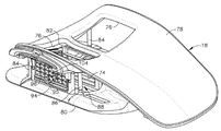
図1〜図3では、MRI適合生検システム(10)は、その強い磁場及び/または高感度無線周波数(RF)信号検出アンテナとの有害な相互作用を軽減するために、MRI機(図示せず)を含有する遮蔽室の外側に設置され得る、または、少なくとも、離間され得る、制御モジュール(12)を有する。米国特許第6,752,768号(全体として参照により本明細書によって組み込まれる)に説明されるように、事前にプログラムされた機能の範囲は、組織サンプルを取ることを補助する制御モジュール(12)に組み込まれ得る。制御モジュール(12)は、定位アセンブリ(15)と共に使用される生検デバイス(14)を制御及び電力供給する。生検デバイス(14)は、MRIまたは他の撮像機械の構台(図示せず)に設置され得るブレストコイル(18)に取り付けられた定位具(16)によって位置付けられ、及び誘導される。
I. Overview of an exemplary MRI biopsy control module In FIGS. 1-3, the MRI conforming biopsy system (10) mitigates harmful interactions with its strong magnetic field and / or sensitive radio frequency (RF) signal detection antennas. To do so, it has a control module (12) that can be installed outside the shielding chamber containing the MRI machine (not shown), or at least can be separated. As described in US Pat. No. 6,752,768 (incorporated herein by reference in its entirety), a range of pre-programmed functions assists in taking tissue samples (12). ) Can be incorporated. The control module (12) controls and powers the biopsy device (14) used with the stereotactic assembly (15). The biopsy device (14) is positioned and guided by a stereotactic tool (16) attached to a breast coil (18) that can be installed on the gantry (not shown) of an MRI or other imaging machine.
本実施例では、制御モジュール(12)は、生検デバイス(14)に機械的に、電気的に、及び空気圧で結合され、これにより、MRI機の強い磁場及び高感度RF受信構成要素から離間される必要がある構成要素は隔離され得る。ケーブルマネジメントスプール(20)は、制御モジュール(12)の側から突き出るケーブルマネジメント取り付けサドル(22)に設置される。ケーブルマネジメントスプール(20)の巻物は、各々、制御信号を通信させるための及びカッター回転運動/前進運動のための、電気ケーブル(24)及び機械ケーブル(26)の対である。具体的には、電気ケーブル(24)及び機械ケーブル(26)のそれぞれは、制御モジュール(12)の中の各々の電気ポート(28)及び機械ポート(30)に接続される一端と、生検デバイス(14)のホルスタ部(32)に接続される別の端とを有する。ドッキングカップ(34)(使用中ではないとき、ホルスタ部(32)を保持し得る)は、ステーションマウンティングブラケット(36)をドッキングすることによって、制御モジュール(12)に留められる。制御モジュール(12)に関連付けられるように上記に説明した係る構成要素は、単なる選択的なものであることを理解されたい。 In this embodiment, the control module (12) is mechanically, electrically, and pneumatically coupled to the biopsy device (14), thereby separating it from the strong magnetic field and sensitive RF receiving components of the MRI machine. The components that need to be isolated can be isolated. The cable management spool (20) is installed in the cable management mounting saddle (22) protruding from the side of the control module (12). The scroll of cable management spool (20) is a pair of electrical cable (24) and mechanical cable (26) for communicating control signals and for cutter rotation / forward movement, respectively. Specifically, each of the electrical cable (24) and the mechanical cable (26) is biopsied with one end connected to each electrical port (28) and mechanical port (30) in the control module (12). It has another end connected to the holster section (32) of the device (14). The docking cup (34) (which may hold the holster section (32) when not in use) is fastened to the control module (12) by docking the station mounting bracket (36). It should be understood that such components as described above as associated with the control module (12) are merely selective.
壁に搭載される界面ロックボックス(38)は、テザー(40)を、制御モジュール(12)上のロックアウト部(42)に提供する。テザー(40)は、MRI機または他の機械に近すぎるような制御モジュール(12)の不注意の位置付けを防ぐために、独特に終端し、短い長さになっている。直線状の囲い(44)では、テザー(40)、電気ケーブル(24)、及び機械ケーブル(26)が、制御モジュール(12)のケーブルの各々のポート(42、28、30)の位置に合い得る。 The wall-mounted interface lock box (38) provides the tether (40) to the lockout section (42) on the control module (12). The tether (40) is uniquely terminated and short in length to prevent inadvertent positioning of the control module (12) so that it is too close to the MRI machine or other machine. In the linear enclosure (44), the tether (40), electrical cable (24), and mechanical cable (26) align with the respective ports (42, 28, 30) of the cable of the control module (12). obtain.
真空補助は、制御モジュール(12)と、液体及び固体破片を捕る真空キャニスタ(50)の出口ポート(48)との間に接続する第1の真空ライン(46)によって提供される。チューブキット(52)は、制御モジュール(12)と生検デバイス(14)との間の空気の連通を完全にする。具体的には、第2の真空ライン(54)は、真空キャニスタ(50)の入口ポート(56)に接続される。第2の真空ライン(54)は、生検デバイス(14)に取り付けられる2つの真空ライン(58、60)に分かれる。生検デバイス(14)がホルスタ部(32)に設置された状態で、制御モジュール(12)は機能点検を行う。生理食塩水は、例えば、潤滑剤としての役割を果たすように、ならびに真空密封を達成することを補助するために、及び/または他の目的のために、生検デバイス(14)に手動で注入され得る、またはそうでなければ、生検デバイス(14)に導入され得る。制御モジュール(12)は、生検デバイス(14)の中のカッター機構(図示せず)を作動させ、本実施例の生検デバイス(14)のカッターの進行をすべて監視する。機械ケーブル(26)の中または生検デバイス(14)の内部の縛りは、随意に、機械ケーブル(26)を曲げるために付与されたモータ力、及び/または機械ケーブル(26)の各端における回転速度または回転位置を比較する際に感知された機械ケーブル(26)の曲がり量に関連して監視され得る。 Vacuum aid is provided by a first vacuum line (46) connecting between the control module (12) and the outlet port (48) of the vacuum canister (50) that captures liquid and solid debris. The tube kit (52) completes the communication of air between the control module (12) and the biopsy device (14). Specifically, the second vacuum line (54) is connected to the inlet port (56) of the vacuum canister (50). The second vacuum line (54) is divided into two vacuum lines (58, 60) attached to the biopsy device (14). With the biopsy device (14) installed in the holster section (32), the control module (12) performs a functional check. Saline is manually injected into the biopsy device (14), for example to serve as a lubricant and / or for other purposes to assist in achieving vacuum sealing. It may or may not be introduced into the biopsy device (14). The control module (12) activates a cutter mechanism (not shown) in the biopsy device (14) and monitors all the progress of the cutter in the biopsy device (14) of this embodiment. Binding inside the machine cable (26) or inside the biopsy device (14) is optionally at the motor force applied to bend the machine cable (26) and / or at each end of the machine cable (26). It can be monitored in relation to the amount of bending of the mechanical cable (26) sensed when comparing rotation speeds or positions.
リモコンキーパッド(62)(ホルスタ部(32)から取り外し可能である)は、本実施例において、電気ケーブル(24)を介して制御パネル(12)に通信し、生検デバイス(14)の臨床医の制御を向上させ、特に、他の方法での生検デバイス(14)自体であろう制御が定位具(16)への挿入後に容易にアクセス可能ではないとき、及び/または制御モジュール(12)の設置が不都合に離れているとき(例えば、30フィート離れている)に、制御を向上させる。しかしながら、本明細書に説明される他の構成要素と同様に、リモコンキーパッド(62)は、単なる選択的なものであり、所望されるように、修正、置換、補足、または省略され得る。本実施例では、ホルスタ部(32)の後端部サムホイール(63)は、また、組織サンプルが取られた側を回転するために、挿入後に容易にアクセス可能である。 The remote control keypad (62) (removable from the holster section (32)) communicates with the control panel (12) via the electrical cable (24) in this embodiment to clinically use the biopsy device (14). Improves physician control, especially when controls that would otherwise be the biopsy device (14) itself are not readily accessible after insertion into the stereotactic device (16) and / or the control module (12). ) Is inconveniently separated (eg, 30 feet away) to improve control. However, like the other components described herein, the remote control keypad (62) is merely selective and may be modified, replaced, supplemented, or omitted as desired. In this embodiment, the rear end thumbwheel (63) of the holster portion (32) is also readily accessible after insertion to rotate the side from which the tissue sample was taken.
当然ながら、上記に説明した制御モジュール(12)は、単なる一実施例である。任意の他の適切な種類の制御モジュール(12)及び関連構成要素を使用し得る。単なる例として、制御モジュール(12)は、代わりに、米国特許公開第2008/0228103号の題名「Vacuum Timing Algorithm for Biopsy Device」(2008年9月18日に公開され、その開示が本明細書に参照により組み込まれる)の教示に従って構築され、動作可能であり得る。別の単なる例示的な実施例として、制御モジュール(12)は、代わりに、米国特許第8,328,732号の題名「Control Module Interface for MRI Biopsy Device」(2012年12月11日に発行され、その開示が参照により本明細書に組み込まれる)の教示に従って構成され、動作可能であり得る。代替として、制御モジュール(12)は、任意の他の適切な構成要素、特徴、構成、機能、動作性等を有し得る。制御モジュール(12)及び関連構成要素の他の適切な変形例は、本明細書の教示を鑑みて、当業者に明らかであろう。 As a matter of course, the control module (12) described above is merely an embodiment. Any other suitable type of control module (12) and related components may be used. As a mere example, the control module (12) was instead published in US Patent Publication No. 2008/0228103 under the title "Vacum Timing Algorithm for Biopsy Device" (September 18, 2008, the disclosure of which is herein. Can be constructed and operational according to the teachings (incorporated by reference). As another mere exemplary embodiment, the control module (12) was instead published in US Pat. No. 8,328,732, entitled "Control Module Interface for MRI Biopsy Device" (December 11, 2012). , The disclosure of which is incorporated herein by reference), and may be configured and operational. Alternatively, the control module (12) may have any other suitable components, features, configurations, functions, operability, and the like. Other suitable modifications of the control module (12) and related components will be apparent to those of skill in the art in light of the teachings herein.
II.例示的定位アセンブリ
定位フレームワーク(68)の左平行上部ガイド(64)及び右平行上部ガイド(66)は、ブレストコイル(18)の患者支持プラットフォーム(78)の中に形成された選択されたブレストアパチャ(76)の下側(74)に、及びその各側に取り付けられる左平行上部トラック(70)及び右平行上部トラック(72)の内部で、各々、横方向に調整可能に受容される。ブレストコイル(18)の基部(80)は、ブレストアパチャ(76)の間の患者支持プラットフォーム(78)に取り付けられる中心線柱(82)によって接続される。また、各々のブレストアパチャ(76)の周りに離間するような各側の一対の外側垂直支持柱(84、86)は、各々、定位具(16)が内部に存在する横凹部(88)を画定する。
II. The left parallel upper guide (64) and the right parallel upper guide (66) of the exemplary stereotactic assembly stereotaxic framework (68) are selected breasts formed within the patient support platform (78) of the breast coil (18). Within the left parallel upper track (70) and the right parallel upper track (72) attached to the underside (74) of the aperture (76) and to each side thereof, each is laterally adjustable. The base (80) of the breast coil (18) is connected by a centerline column (82) attached to the patient support platform (78) between the breast apertures (76). Also, the pair of outer vertical support columns (84, 86) on each side that are spaced apart around each blast aperture (76) each have a lateral recess (88) in which the orientation tool (16) is present. Define.
本実施例では、患者の胸部が各々横凹部(88)の内部でブレストアパチャ(76)にぶら下がるように吊るされることを認識されたい。便宜上、本明細書では、慣例が、定位具(16)に参照される乳房組織内でデカルト座標によって疑わしい病変を特定するために使用され、その後、生検デバイス(14)を形成するホルスタ部(32)に係合するプローブ(91)の針(90)等の器具を選択的に位置付けるために使用される。当然ながら、任意の他の種類の座標系または標的技術を使用し得る。生検デバイス(10)の不干渉使用を向上させるために、特に、閉じた穴のMRI機の狭い領域内の再撮像の繰り返しのために、生検システム(10)は、また、カニューレ(94)によって囲まれるオブチュレータ(92)を誘導し得る。挿入の深度は、針(90)またはカニューレ(94)のいずれかの縦方向に位置付けられる深度停止デバイス(95)によって制御される。代替として、挿入の深度は、任意の他の適切な様式で制御され得る。 It should be noted that in this example, each patient's chest is hung inside a transverse recess (88) so as to hang from a blast aperture (76). For convenience, in the present specification, a convention is used to identify a suspicious lesion by Cartesian coordinates in the breast tissue referred to by the stereotaxic instrument (16), followed by a holster section (14) forming the biopsy device (14). It is used to selectively position an instrument such as the needle (90) of the probe (91) that engages 32). Of course, any other kind of coordinate system or targeting technique can be used. To improve the non-interfering use of the biopsy device (10), especially for repeated reimaging within a narrow area of the MRI machine with closed holes, the biopsy system (10) is also cannulated (94). ) Can induce an obturator (92) surrounded by. The depth of insertion is controlled by a depth stop device (95) positioned vertically on either the needle (90) or the cannula (94). Alternatively, the depth of insertion can be controlled in any other suitable manner.
このガイダンスは、本実施例では、具体的に、横フェンスによって提供され、左平行上部ガイド(64)及び右平行上部ガイド(66)の下に取り付けられた横方向調節可能外側三面板ブラケット(98)の内部で受ける格子板(96)として示される。同様に、中央板(100)として示される患者の胸郭の中央面に対する中央フェンスは、ブレストコイル(18)の中に設置されるとき、中心線柱(82)に近い左平行上部ガイド(64)及び右平行上部ガイド(66)の下に取り付けられた内側三面板ブラケット(102)の内部で受容される。器具(例えば、プローブ(91)の針(90)、オブチュレータ(92)/カニューレ(94)等)の挿入点をさらに純化するために、ガイドキューブ(104)は、格子板(96)に挿入され得る。 This guidance is provided specifically by the lateral fence in this embodiment and is laterally adjustable outer three-sided bracket (98) mounted under the left parallel upper guide (64) and the right parallel upper guide (66). ) Is shown as a grid plate (96) received inside. Similarly, the central fence against the central surface of the patient's thorax, shown as the central plate (100), is the left parallel upper guide (64) close to the central line column (82) when installed in the breast coil (18). And received inside the inner three-sided bracket (102) mounted under the right parallel upper guide (66). The guide cube (104) is inserted into the grid plate (96) to further purify the insertion point of the instrument (eg, needle (90) of probe (91), obturator (92) / cannula (94), etc.). obtain.
本実施例では、選択された胸は、中央板(100)によって内側(中央側)に沿って及び格子板(96)によって胸の外側(横側)で圧迫され、後者(格子板(96))はX−Y平面を画定する。X軸は、直立した患者に対して垂直(矢状方向)であり、定位具(16)の外部露出部に対面する臨床医によって視認されるように左右軸に対応する。ブレストの中央側に向かって延在するこのX−Y平面に垂直なものはZ軸であり、Z軸は、一般的に、生検デバイス(14)の針(90)またはオブチュレータ(92)/カニューレ(94)の挿入の配向及び深度に対応する。分かり易くするために、用語「Z軸」は、「貫通軸」と交換可能に使用され得るが、後者(貫通軸)は、患者の挿入点を特定するために使用される空間座標に対して直角であり得る、または、直角ではない場合がある。本明細書に説明される定位具(16)の形態は、便利なまたは臨床的に有利な角度で、病変に対するX−Y軸に対する非直交貫通軸が可能になる。 In this embodiment, the selected breast is compressed along the medial side (central side) by the central plate (100) and on the lateral side (lateral side) of the breast by the grid plate (96), the latter (lattice plate (96)). ) Defines the XY plane. The X-axis is perpendicular (sagittal) to the upright patient and corresponds to the left-right axis as visible by the clinician facing the externally exposed portion of the stereotaxic instrument (16). Perpendicular to this XY plane extending towards the center of the breast is the Z axis, which is generally the needle (90) or obturator (92) / of the biopsy device (14). Corresponds to the orientation and depth of insertion of the cannula (94). For clarity, the term "Z-axis" may be used interchangeably with "penetration axis", while the latter (penetration axis) refers to the spatial coordinates used to identify the patient's insertion point. It may or may not be a right angle. The morphology of the orientation tool (16) described herein allows for a non-orthogonal penetrating axis with respect to the XY axis for the lesion at a convenient or clinically advantageous angle.
上記に説明した定位アセンブリ(15)は、単なる一実施例であることを理解されたい。限定ではないが、上記に説明したものと異なるブレストコイル(18)及び/または定位具(16)を使用する定位アセンブリ(15)を含む任意の他の適切な種類の定位アセンブリ(15)を使用し得る。定位アセンブリ(15)に関する他の適切な構成要素、特徴、構成、機能、動作性等は、本明細書の教示を鑑みて、当業者に明らかであろう。 It should be understood that the stereotactic assembly (15) described above is merely an embodiment. Use any other suitable type of localization assembly (15), including, but not limited to, a localization assembly (15) that uses a different breast coil (18) and / or orientation tool (16) than that described above. Can be. Other suitable components, features, configurations, functions, operability, etc. relating to the stereotactic assembly (15) will be apparent to those of skill in the art in light of the teachings herein.
III.例示的な生検デバイス
図1に示されるように、生検デバイス(14)の1つの形態は、ホルスタ(32)及びプローブ(91)を備え得る。例示的なホルスタ部(32)は、制御モジュール(12)を扱う上記のセクションで前に説明されている。以下の段落は、さらに詳細に、プローブ(91)と、関連構成要素及び関連デバイスとを説明する。
III. Illustrative Biopsy Device As shown in FIG. 1, one form of the biopsy device (14) may comprise a holster (32) and a probe (91). An exemplary holster section (32) is previously described in the section above dealing with the control module (12). The following paragraphs describe in more detail the probe (91) and related components and devices.
本実施例では、カニューレ(94)及びオブチュレータ(92)を備えるターゲッティングセット(89)は、プローブ(91)に関連付けられる。具体的には、図7、図8、及び図9に示されるように、オブチュレータ(92)は、カニューレ(94)内で摺動し、それらの組み合わせは、ガイドキューブ(104)を通って乳房組織内の生検部位まで誘導される。図3に示すように、次にオブチュレータ(92)をカニューレ(94)から引き抜き、次にプローブ(91)の針(90)をカニューレ(94)に挿入し、次いで生検デバイス(14)を操作して、針(90)を介して乳房から1つ以上の組織サンプルを採取する。 In this embodiment, the targeting set (89) with the cannula (94) and the obturator (92) is associated with the probe (91). Specifically, as shown in FIGS. 7, 8 and 9, the obturator (92) slides within the cannula (94) and their combination passes through the guide cube (104) to the breast. It is guided to the biopsy site in the tissue. As shown in FIG. 3, the obturator (92) is then withdrawn from the cannula (94), then the needle (90) of the probe (91) is inserted into the cannula (94), and then the biopsy device (14) is operated. Then, one or more tissue samples are taken from the breast via the needle (90).
図8で最もよく見られるように、本実施例のカニューレ(94)は、円筒形ハブ(198)に近位に取り付けられ、カニューレ(94)は、開放遠位端(202)に近接する管腔(196)及び横側口(201)を含む。円筒形ハブ(198)には、横側口(201)を回転させるための外側に表示されるサムホイール(204)がある。円筒状ハブ(198)は内部凹部(206)を有し、内部凹部(206)は、ダックビルシール(208)、ワイパーシール(211)、及びシールリテーナ(212)を囲み、管腔(196)が空であるときに流体密封をもたらし、挿入されたオブチュレータ(92)に密封をもたらす。カニューレ(94)の外側表面に沿って縦方向に離間された測定印(213)は、視覚的に、及びおそらく物理的に、図1の深度停止デバイス(95)を特定する手段を備える。 As most often seen in FIG. 8, the cannula (94) of this embodiment is attached proximal to the cylindrical hub (198) and the cannula (94) is a tube close to the open distal end (202). Includes lumen (196) and lateral mouth (201). The cylindrical hub (198) has a thumbwheel (204) that is visible on the outside for rotating the lateral opening (201). The cylindrical hub (198) has an internal recess (206), the internal recess (206) surrounding the duck bill seal (208), wiper seal (211), and seal retainer (212), and the lumen (196). It provides a fluid seal when empty and provides a seal to the inserted obturator (92). The measuring marks (213), vertically spaced along the outer surface of the cannula (94), provide means for visually and perhaps physically identifying the depth stop device (95) of FIG.
本実施例のオブチュレータ(92)は、対応する特徴があるいくつかの構成要素を組み込んでいる。例えば、オブチュレータ(92)は、流体管腔(216)を含むシャフト(214)を含み、流体管腔(216)は、イメージ可能側のノッチ(218)と近位ポート(220)との間で連通している。シャフト(214)は、穿刺端(222)がカニューレ(94)の遠位端(202)から出るように延在するように、縦方向に寸法決めされる。オブチュレータサムホイールキャップ(224)は、近位ポート(220)を囲み、ロッキング特徴部(226)を含み、ロッキング特徴部(226)は、イメージ可能なサイドノッチ(218)がカニューレ(94)の中の横側口(201)に位置が合うことを確実にするために、カニューレサムホイール(204)に係合する可視角度インジケータ(228)を含む。オブチュレータ密封キャップ(230)は、オブチュレータサムホイールキャップ(224)の近位に係合し、流体管腔(216)を閉鎖し得る。本実施例のオブチュレータ密封キャップ(230)は、ロッキングまたは定位特徴部(232)を含み、ロッキングまたは定位特徴部(232)は、オブチュレータサムホイールキャップ(224)(剛体材料、軟質材料、または弾性材料から作られ得る)の可視角度インジケータ(228)に対応する可視角度インジケータ(233)を含む。図9では、ガイドキューブ(104)は、格子板(96)を通るように誘導されたオブチュレータ(92)と、カニューレ(94)とを有する。 The obturator (92) of this embodiment incorporates several components with corresponding characteristics. For example, the obturator (92) includes a shaft (214) that includes a fluid lumen (216), which is between the notch (218) on the imageable side and the proximal port (220). Communicate. The shaft (214) is longitudinally sized so that the puncture end (222) extends out of the distal end (202) of the cannula (94). The obturator thumb wheel cap (224) surrounds the proximal port (220) and includes a locking feature (226), where the locking feature (226) has an imaginable side notch (218) in the cannula (94). Includes a visible angle indicator (228) that engages the cannula thumb wheel (204) to ensure alignment with the lateral opening (201) of the. The obturator sealing cap (230) may engage proximal to the obturator thumb wheel cap (224) and close the fluid lumen (216). The obturator sealing cap (230) of this embodiment includes a locking or localization feature (232), and the locking or localization feature (232) is an obturator thumb wheel cap (224) (rigid material, soft material, or elastic material). Includes a visible angle indicator (233) corresponding to the visible angle indicator (228) of (which can be made from). In FIG. 9, the guide cube (104) has an obturator (92) guided through a grid plate (96) and a cannula (94).
本実施例のオブチュレータ(92)が中空であるが、オブチュレータ(92)は、代替として、オブチュレータ(92)が内部管腔を画定しないように、実質的に固定内部に有し得ることを理解されたい。加えて、オブチュレータ(92)は、いくつかの形態では、サイドノッチ(218)が不足し得る。オブチュレータ(92)に関する他の適切な構成要素、特徴、構成、機能、動作性等は、本明細書の教示を鑑みて、当業者に明らかであろう。同様に、カニューレ(94)は、いくつかの方法で変わり得る。例えば、いくつかの他の形態では、カニューレ(94)は、閉じた遠位端(202)を有する。別の単なる例示的な実施例として、カニューレ(94)は、穿刺端(222)を有するオブチュレータ(92)の代わりに、閉じた穿刺端(222)を有し得る。いくつかの係る形態では、オブチュレータ(92)は、単純に、とがっていない遠位端を有し得る。または、オブチュレータ(92)の遠位端は、任意の他の適切な構造、特徴、または構成を有し得る。カニューレ(94)に関する他の適切な構成要素、特徴、構成、機能、動作性等は、本明細書の教示を鑑みて、当業者に明らかであろう。さらに、いくつかの形態では、オブチュレータ(92)またはカニューレ(94)の1つまたは両方は、完全に省略され得る。例えば、プローブ(91)の針(90)は、カニューレ(94)を介してガイドキューブ(104)に挿入されることなく、ガイドキューブ(104)に直接挿入され得る。 Although the obturator (92) of this embodiment is hollow, it is understood that the obturator (92) can, as an alternative, have a substantially fixed interior so that the obturator (92) does not demarcate the internal lumen. sea bream. In addition, the obturator (92) may lack side notches (218) in some forms. Other suitable components, features, configurations, functions, operability, etc. relating to the obturator (92) will be apparent to those of skill in the art in light of the teachings herein. Similarly, the cannula (94) can be varied in several ways. For example, in some other forms, the cannula (94) has a closed distal end (202). As another mere exemplary embodiment, the cannula (94) may have a closed puncture end (222) instead of an obturator (92) with a puncture end (222). In some such embodiments, the obturator (92) may simply have a blunt distal end. Alternatively, the distal end of the obturator (92) may have any other suitable structure, feature, or configuration. Other suitable components, features, configurations, functions, operability, etc. relating to the cannula (94) will be apparent to those of skill in the art in light of the teachings herein. Moreover, in some forms, one or both of the obturator (92) or the cannula (94) may be omitted altogether. For example, the needle (90) of the probe (91) can be inserted directly into the guide cube (104) without being inserted into the guide cube (104) via the cannula (94).
プローブ(91)(または針(90))と共に使用され得る別の構成要素は、深度停止デバイス(95)である。深度停止デバイス(95)は、カニューレ(94)及びオブチュレータ(92)(または針(90))を、所望よりもさらに挿入されることを防止するように動作可能である任意の適切な構成であり得る。例えば、深度停止デバイス(95)は、カニューレ(94)(または針(90))の外部に位置付けられ得、カニューレ(94)がガイドキューブに挿入される範囲を制限するように構成され得る。深度停止デバイス(95)による係る制限が、さらに、カニューレ(94)及びオブチュレータ(92)(または針(90))の組み合わせが患者の胸部に挿入され得る深度の制限を提供し得ることを理解されたい。さらに、係る制限は、オブチュレータ(92)がカニューレ(94)から引き出され、ニードル(90)がカニューレ(94)に挿入された後、生検デバイス(14)が1つ以上の組織サンプルを獲得する患者の胸部内の深さを確立し得ることを理解されたい。生検システム(10)と共に使用され得る例示的深度停止デバイス(95)は、米国特許公開第2007/0255168号、題名「Grid and Rotatable Cube Guide Localization Fixture for Biopsy Device」(2007年11月1日に公開され、先に言及したように参照により本明細書に組み込まれる)に説明されている。 Another component that can be used with the probe (91) (or needle (90)) is the depth stop device (95). The depth stop device (95) is any suitable configuration capable of operating the cannula (94) and the obturator (92) (or needle (90)) to prevent further insertion than desired. obtain. For example, the depth stop device (95) may be located outside the cannula (94) (or needle (90)) and may be configured to limit the extent to which the cannula (94) can be inserted into the guide cube. It is understood that such limitations by the depth stop device (95) can further provide a limitation on the depth at which the combination of cannula (94) and obturator (92) (or needle (90)) can be inserted into the patient's chest. sea bream. Further, such limitation is that the biopsy device (14) acquires one or more tissue samples after the obturator (92) is withdrawn from the cannula (94) and the needle (90) is inserted into the cannula (94). It should be understood that the depth within the patient's chest can be established. An exemplary depth stop device (95) that can be used with the biopsy system (10) is U.S. Patent Publication No. 2007/0255168, entitled "Grid and Rotatable Cube Guide Localization Fixture for Biopsy Device" (November 1, 2007). Published and incorporated herein by reference as previously mentioned).
本実施例では、上記に留意したように、生検デバイス(14)は、カニューレ(94)及びオブチュレータ(92)の組み合わせが患者の胸部内の所望の場所に挿入された後、ならびにオブチュレータ(92)がカニューレ(94)から取り外された後、カニューレ(94)に挿入され得るニードル(90)を含む。本実施例の針(90)は、針(90)がカニューレ(94)の管腔(196)に挿入されるとき、カニューレ(94)の横側口(201)と実質的に整列されるように構成される横側口(図示せず)を備える。本実施例のプローブ(91)は、さらに、回転カッター及び並進カッター(図示せず)を備え、回転カッター及び並進カッターは、ホルスタ(32)の中の構成要素によって動作され、カニューレ(94)の横側口(201)及び針(90)の横側口を通るように突出する組織を切断するように動作可能である。切断された組織サンプルは、任意の適切な方式で、生検デバイス(14)から回収され得る。 In this example, as noted above, the biopsy device (14) is provided after the combination of cannula (94) and obturator (92) has been inserted at the desired location within the patient's chest, as well as the obturator (92). ) Includes a needle (90) that can be inserted into the cannula (94) after it has been removed from the cannula (94). The needle (90) of this embodiment is substantially aligned with the lateral opening (201) of the cannula (94) when the needle (90) is inserted into the lumen (196) of the cannula (94). It is equipped with a side opening (not shown) configured in. The probe (91) of this embodiment further comprises a rotary cutter and a translational cutter (not shown), the rotary cutter and the translational cutter being operated by the components in the holster (32) and of the cannula (94). It can be operated to cut the tissue protruding through the lateral opening (201) and the lateral opening of the needle (90). The cut tissue sample can be recovered from the biopsy device (14) in any suitable manner.
使い捨てプローブアセンブリ(91)を利用するような生検システム(10)を上記で説明したが、他の適切なプローブアセンブリ及び生検デバイスアセンブリを利用し得ることを理解されたい。単なる例として、他の適切な生検デバイスは、以下の特許の教示の少なくとも一部に従って、構成され、動作可能であり得る。その特許として、米国特許第8,206,316号、題名「Tetherless Biopsy Device with Reusable Portion」(2012年6月26日に発行され、その開示が参照により本明細書に組み込まれる)、米国特許第8,277,394号、題名「Multi−Button Biopsy Device」(2012年10月2日に発行され、その開示が参照によって本明細書に組み込まれる)、及び/または米国特許公開第2012/0065542号、題名「Biopsy Device Tissue Sample Holder with Removable Tray」(2012年3月15日に公開され、その開示が参照によって本明細書に組み込まれる)が挙げられる。さらに別の単なる例示的な実施例として、他の適切な生検デバイスは、以下の特許の教示の少なくとも一部に従って、構成され、動作可能であり得る。米国特許公開第2010/0160824号(その開示が参照によって本明細書に組み込まれる)、米国特許公開第2013/0144188号、題名「Biopsy Device with Slide−In Probe」(2013年6月6日に公開され、その開示が参照によって本明細書に組み込まれる)、米国特許公開第2013/0324882号、題名「Control for Biopsy Device」(2013年12月5日に公開され、その開示が参照によって本明細書に組み込まれる)、米国特許公開第2014/0039343号の題名「Biopsy System」(2014年2月6日に公開され、その開示が参照により本明細書に組み込まれる)、及び/または米国特許公開第2015/0065913号、題名「Tissue Collection Assembly for Biopsy Device」(2015年3月5日に公開され、その開示が参照により本明細書に組み込まれる)が挙げられる。 A biopsy system (10) that utilizes a disposable probe assembly (91) has been described above, but it should be appreciated that other suitable probe and biopsy device assemblies may be utilized. As a mere example, other suitable biopsy devices may be configured and operational according to at least some of the teachings of the patent below. As its patents, U.S. Pat. No. 8,206,316, entitled "Tetherless Biopsy Device with Reusable Portion" (issued June 26, 2012, the disclosure of which is incorporated herein by reference), U.S. Pat. No. 8,277,394, entitled "Multi-Button Biopsy Device" (issued October 2, 2012, the disclosure of which is incorporated herein by reference), and / or US Patent Publication No. 2012/0065542. , Titled "Biopsy Device Patent Holder with Removable Play" (published March 15, 2012, the disclosure of which is incorporated herein by reference). Yet another mere exemplary embodiment, other suitable biopsy devices may be configured and operational according to at least some of the teachings of the patent below. US Pat. And its disclosure is incorporated herein by reference), US Patent Publication No. 2013/0324882, entitled "Control for Biopsy Device" (published December 5, 2013, the disclosure of which is hereby by reference US Pat. 2015/0065913, entitled "Patent Collection Associate for Biopsy Device" (published March 5, 2015, the disclosure of which is incorporated herein by reference).
本明細書に説明されるようなシステム(10)のさまざまな代替構成要素と併せて使用され得る生検デバイスのさらに他の適切な形態は、当業者に明らかであろう。 Yet other suitable forms of biopsy devices that may be used in conjunction with the various alternative components of the system (10) as described herein will be apparent to those of skill in the art.
IV.例示的なガイドキューブ
いくつかの形態では、ガイドキューブは、1つ以上の縁及び面によって画定される本体を備え得る。本体は、1つ以上のガイド孔または他の種類の通路を備えてもよく、このガイド孔または他の種類の通路は、ガイドキューブの面の間を延在し、生検デバイス(14)または生検デバイス(14)の一部(例えば、生検デバイス(14)の針(90)、カニューレ(94)及びオブチュレータ(92)の組み合わせ等)等の器具を誘導するように使用され得る。ガイドキューブは、1軸、2軸、または3軸を中心に回転可能であり、ガイドキューブの1つ以上のガイド孔またはガイド通路を所望の位置に位置付け得る。
IV. Illustrative Guide Cube In some embodiments, the guide cube may comprise a body defined by one or more edges and faces. The body may be provided with one or more guide holes or other types of passages, the guide holes or other types of passages extending between the faces of the guide cubes, the biopsy device (14) or It can be used to guide an instrument such as a portion of the biopsy device (14) (eg, a combination of a needle (90), a cannula (94) and an obturator (92) of the biopsy device (14)). The guide cube is rotatable about one axis, two axes, or three axes, and one or more guide holes or guide passages of the guide cube can be positioned in a desired position.
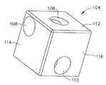
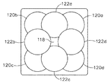
図4において、ガイドキューブ(104)は中心ガイド孔(106)と、コーナーガイド孔(108)と、中心外れガイド孔(110)とを含み、これらは、各々の面(112、114、116)の反対側の対の間を相互に対して直角に通る。2軸のガイドキューブ(104)を選択的に回転することによって、面(112、114、116)の対の1つは、非回転位置に近位に整列され得、次に、選択された近位面(112、114、116)は、随意に、1/4回転、1/2回転、または3/4回だけ回転する。それによって、9つのガイド位置(118)(すなわち、中心ガイド孔(106)を使用する)、(120a〜120d)(すなわち、コーナーガイド孔(108))、(122a〜122d)(すなわち、中心外れガイド孔(110)を使用する)の1つは、図5に示されるように、近位に露出され得る。 In FIG. 4, the guide cube (104) includes a central guide hole (106), a corner guide hole (108), and an off-center guide hole (110), which are the respective surfaces (112, 114, 116). Pass between pairs on opposite sides at right angles to each other. By selectively rotating the biaxial guide cube (104), one of the pairs of faces (112, 114, 116) can be aligned proximally to the non-rotating position and then selected near. The positions (112, 114, 116) are optionally rotated only 1/4 turn, 1/2 turn, or 3/4 turn. Thereby, nine guide positions (118) (ie, using the central guide hole (106)), (120a-120d) (ie, corner guide holes (108)), (122a-122d) (ie, off-center). One of the guide holes (110)) can be exposed proximally, as shown in FIG.
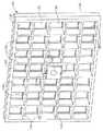
図6では、2軸回転可能ガイドキューブ(104)は、近位側から、格子板(96)内の複数の四角形凹部(130)の1つに挿入されるようにサイズ決定され、四角形凹部(130)は、垂直バー(132)及び水平バー(134)を交差させることによって形成される。ガイドキューブ(104)は、格子板(96)の前面に取り付けられた支持基板(136)によって格子板(96)を通って通過することが防止される。支持基板(136)は、各四角形凹部(130)の内部の中心にある各々の四角形開口部(138)を含み、ガイドキューブ(104)の前面を捕るには十分であるがガイド孔(104、106、108)を塞ぐほど大きくない縁部(140)を形成する。四角形凹部(130)の深度は、ガイドキューブ(104)よりも小さく、それによって、格子板(96)をつかみ及びそこから抜き取るために、ガイドキューブ(104)の近位部(142)を露出する。格子板(96)の支持基板(136)はいくつかの形態では全て省略され得ることを、本明細書の教示に基づいて当業者は認識するだろう。支持基板(136)がない、いくつかの係る形態では、下記により詳細に説明されるようなガイドキューブの他の特徴は、格子板内部でガイドキューブに堅固に及び取り外し可能に適合するように使用され得る。しかしながら、係る他の特徴は、また、支持基板(136)を部分的に、または全体的に省略する代わりに、格子板(96)等の支持基板(136)を有する格子板と組み合わせて使用され得る。 In FIG. 6, the biaxially rotatable guide cube (104) is sized to be inserted from the proximal side into one of the plurality of square recesses (130) in the grid plate (96). 130) is formed by crossing a vertical bar (132) and a horizontal bar (134). The guide cube (104) is prevented from passing through the grid plate (96) by the support substrate (136) attached to the front surface of the grid plate (96). The support substrate (136) includes each square opening (138) in the center of the interior of each square recess (130), which is sufficient to capture the front surface of the guide cube (104) but with guide holes (104, It forms an edge (140) that is not large enough to block 106, 108). The depth of the rectangular recess (130) is smaller than that of the guide cube (104), thereby exposing the proximal portion (142) of the guide cube (104) in order to grab and remove the grid plate (96). .. Those skilled in the art will recognize that the support substrate (136) of the grid plate (96) may be omitted altogether in some forms, based on the teachings herein. In some such embodiments without a support substrate (136), other features of the guide cube, as described in more detail below, are used to fit the guide cube firmly and detachably inside the grid plate. Can be done. However, such other features are also used in combination with a grid plate having a support substrate (136), such as a grid plate (96), instead of omitting the support substrate (136) partially or entirely. obtain.
いくつかの他の形態では、ガイドキューブ(104)は、以下の特許の教示の少なくとも一部に従って、構成され、動作可能である、代替のガイドキューブまたは他のガイド構造と交換される。その特許として、米国特許公開第2015/0025414号の題名「Biopsy Device Targeting Features」(2015年1月22日に公開され、その開示が参照により本明細書に組み込まれる)が挙げられる。 In some other form, the guide cube (104) is replaced with an alternative guide cube or other guide structure that is configured and operational according to at least some of the teachings of the patent below. The patent includes the title "Biopsy Device Targeting Features" of US Patent Publication No. 2015/0025414 (published January 22, 2015, the disclosure of which is incorporated herein by reference).
V.二重回転機能を備えた例示的な深度停止デバイス
場合によっては、深度停止デバイスをカニューレと係合させて患者の乳房内を貫く深さを制御する単純な機械的手段を設けることを望ましい場合がある。上記の深度停止デバイス(95)等の一部の深度停止デバイスでは、操作者は、カニューレ(94)に係合するために、デバイスを所定の方向に回転させて、深度停止デバイス(95)をカニューレ(94)に対してロックし、続いてロック解除することについて制限されている。しかし、一部の生検の処置で、深度停止デバイス(95)及び/またはカニューレ(94)を取り巻くさまざまな機器が、深度停止デバイス(95)を一方向に回転させる際に困難を呈する場合がある。そのため、デバイスをいずれかの方向に回転させることにより、カニューレ(94)と係合し、ロック状態とロック解除状態との間を移行できる深度停止デバイスを供給することが望ましい場合がある。これは、生検処置間における深度停止デバイスの効果的な使用を簡素化及び迅速化するのに有益であり得る。さらに、深度停止デバイスは、デバイスが確実にロックされた状態まで十分に回転したときに示す触覚型フィードバックを操作者に提示することが望ましい場合がある。これは、深度停止デバイスがカニューレ(94)にしっかりと固定されていることを操作者が双方向で確認することを実現し、それによって深度停止デバイスとカニューレ(94)がゆるく係合している状態を維持する事例を最小限に抑えるのに有益であり得る。
V. An exemplary depth-stop device with counter-rotating capability In some cases, it may be desirable to engage the depth-stop device with a cannula to provide a simple mechanical means of controlling the depth that penetrates the patient's breast. be. In some depth-stop devices, such as the depth-stop device (95), the operator rotates the device in a predetermined direction to engage the cannula (94) with the depth-stop device (95). There are restrictions on locking against the cannula (94) and subsequently unlocking. However, with some biopsy procedures, the various devices surrounding the depth stop device (95) and / or the cannula (94) may present difficulty in rotating the depth stop device (95) in one direction. be. Therefore, it may be desirable to provide a depth stop device that can engage with the cannula (94) and transition between the locked and unlocked states by rotating the device in either direction. This can be beneficial in simplifying and expediting the effective use of depth stop devices between biopsy procedures. In addition, it may be desirable for the depth stop device to provide the operator with tactile feedback that is shown when the device is fully rotated to a securely locked state. This allows the operator to confirm in both directions that the depth stop device is firmly anchored to the cannula (94), whereby the depth stop device and the cannula (94) are loosely engaged. It can be useful in minimizing the cases of maintaining the condition.
他の例では、深度停止デバイスが、カニューレに対してデバイスを設置するための適切な向きの視覚的インジケータを操作者に供給することが望ましい場合がある。上記の深度停止デバイス(95)をはじめとする一部の深度停止デバイスでは、いずれの方向がカニューレ(94)に対して深度停止デバイス(95)を適切に設置するための正しい位置合わせであるか、操作者にとって容易に明白にならない場合がある。したがって、深度停止デバイスが、カニューレ(94)及び/またはガイドキューブ(104)に対するデバイスの適切な位置決めを明確に示すことが望ましい場合がある。これは、生検処置間における深度停止デバイスの効果的な使用をさらに簡素化及び迅速化するのに有益であり得る。 In another example, it may be desirable for the depth stop device to provide the operator with a visual indicator of the proper orientation for installing the device with respect to the cannula. For some depth stop devices, including the depth stop device (95) above, which direction is the correct alignment for proper installation of the depth stop device (95) with respect to the cannula (94). , May not be easily obvious to the operator. Therefore, it may be desirable for the depth stop device to clearly indicate the proper positioning of the device with respect to the cannula (94) and / or the guide cube (104). This can be beneficial in further simplifying and speeding up the effective use of depth stop devices between biopsy procedures.
以下に説明する深度停止デバイスは、上述のさまざまなターゲティングセット(89)及びガイドキューブ(104)のいずれか、ならびに本明細書に記載のさまざまな参照文献に記載のさまざまな外科手術のいずれかに容易に組み込んでもよいことを理解されたい。特に、以下で説明する深度停止デバイスの実施例を使用して、操作者が所定の貫通深度を設定できるようにすることで、MRIガイダンスを使用して患者の乳房の内部をターゲットとする生検デバイスの補助をし得る。以下で説明する深度停止デバイスを使用してもよい他の適切な方法は、本明細書の教示を鑑みた当業者に明らかである。単なる例示で、いくつかの実施例では、深度停止デバイス(1095)は、以下の特許の教示の少なくとも一部に従って構成され、動作可能である。その特許として、米国特許第8,568,333号、題名「Grid and Rotatable Cube Guide Localization Fixture for Biopsy Device」(2013年10月29日に発行)及び、米国出願公開第15/499,950号、題名「Depth Stop Device for Use with Biopsy Targeting Assembly」(2017年4月28日に出願)が挙げられる。これらの開示は、参照により本明細書に組み込まれる。 The depth stop device described below is one of the various targeting sets (89) and guide cubes (104) described above, as well as any of the various surgical procedures described in the various references described herein. Please understand that it may be easily incorporated. In particular, a biopsy targeting the inside of the patient's breast using MRI guidance by allowing the operator to set a given penetration depth using an example of a depth stop device described below. Can assist the device. Other suitable methods of using the depth stop devices described below will be apparent to those of skill in the art in view of the teachings herein. By way of example only, in some embodiments, the depth stop device (1095) is configured and operational according to at least some of the following patented teachings. The patents include US Patent No. 8,568,333, entitled "Grid and Rotary Cube Guide Location Fixed for Biopsy Device" (issued October 29, 2013), and US Application Publication No. 15 / 499,950. The title "Depts Stop Device for Use with Biopsy Targeting Associates" (filed on April 28, 2017) can be mentioned. These disclosures are incorporated herein by reference.
図10は、ターゲティングセット(89)に関して上記に同様に説明したようなカニューレ(94)及び/またはガイドキューブ(104)に関連して使用される例示的な代替の深度停止デバイス(1095)を示す。以下に別段に説明する場合を除いて、深度停止デバイス(1095)は、上述の深度停止デバイス(95)と、多くの点で非常に類似して機能することを理解されたい。深度停止デバイス(1095)は、セラミック等の比較的硬い材料を含む外部ハウジング(1100)を含む。ハウジング(1100)は、一対の端部(1102)と一対のグリップ側部(1104)を含む。グリップ側部(1104)は、深度停止デバイス(1095)をロック解除状態からロック状態に交換可能に移行させるために、操作者によって選択的に操作されるように構成される。深度停止デバイス(1095)は、外部ハウジング(1100)内に配置され、前端開口部(1108)と後端開口部(1110)との間に延びる受容チャネル(1106)をさらに含む。受容チャネル(1106)は、前端開口部(1108)及び後端開口部(1110)を通してカニューレ(94)を受容するように寸法決め及び構成されている。特に、受容チャネル(1106)は、概して、カニューレ(94)の楕円形の外形に対応する楕円形を画定し、そのため、受容チャネル(1106)は、横側口(201)が端部のいずれかの対(1102)と位置を合わせるときに干渉なしにカニューレ(94)を受容するように動作可能である。示されていないが、受容チャネル(1106)は、楕円形/円筒の外形を備えていないカニューレまたは生検器具の軸での回転を補助及び促進するように、図示された断面とは異なる断面を有するサイズ及び形状であってもよいことを理解されたい。 FIG. 10 shows an exemplary alternative depth stop device (1095) used in connection with the cannula (94) and / or the guide cube (104) as similarly described above for the targeting set (89). .. It should be appreciated that the depth stop device (1095) functions in many respects very similar to the depth stop device (95) described above, except as otherwise described below. The depth stop device (1095) includes an outer housing (1100) containing a relatively hard material such as ceramic. The housing (1100) includes a pair of ends (1102) and a pair of grip sides (1104). The grip side portion (1104) is configured to be selectively operated by the operator in order to interchangeably shift the depth stop device (1095) from the unlocked state to the locked state. The depth stop device (1095) is located within the outer housing (1100) and further includes a receiving channel (1106) extending between the front end opening (1108) and the rear end opening (1110). The receiving channel (1106) is sized and configured to receive the cannula (94) through the front end opening (1108) and the rear end opening (1110). In particular, the receiving channel (1106) generally defines an ellipse corresponding to the elliptical outline of the cannula (94), so that the receiving channel (1106) is either ended at the lateral opening (201). It can operate to accept the cannula (94) without interference when aligning with the pair (1102). Although not shown, the receiving channel (1106) has a cross section different from the one shown to assist and facilitate rotation of the cannula or biopsy instrument without an elliptical / cylindrical profile. It should be understood that the size and shape may be possessed.
受容チャネル(1106)は、一対のブレード(1112)及び複数のランプ(1114)をさらに含む。ランプ(1114)は、深度停止デバイス(1095)と一体であり、受容チャネル(1106)に沿って、また開口部(1108、1110)間で、軸方向に延びる。ランプ(1114)は深度停止デバイス(1095)と一体であるように示されているが、ランプ(1114)は、当業者に明らかなように、受容チャネル(1106)に取り付けられた別個の構成要素であり得ることを理解されたい。ランプ(1114)は、カニューレ(94)が受容チャネル(1106)に入る際にランプ(1114)が干渉することなく、深度停止デバイス(1095)がカニューレ(94)をランプの間で受容することができるように、受容チャネル(1106)の周りに、対応するように配置される。言い換えると、ランプ(1114)は、前端開口部(1108)を通して受容されたときに、受容チャネル(1106)を通してカニューレ(94)を方向付けるのを促すように構成される。ランプ(1114)は、受容チャネル(1106)の中へ延びる横向きの全長部または延長部を有している。本実施例では、この横向きの全長部は各ランプ(1114)の軸方向の全長にわたって比較的一定であるように示されているが、他の実施例では、各ランプ(1114)が軸方向に延びるときにこの横向きの全長部を変更できることを理解されたい。例えば、いくつかの実施例では、各ランプ(1114)は、共通する軸に沿って方向付けられた一連の突起として構成され得る。以下にさらに詳細に説明するように、カニューレ(94)が受容チャネル(1106)の中に摺動可能に受容された状態では、ランプ(1114)は、深度停止デバイス(1095)が時計回りまたは反時計回りの方向に選択的に回転すると、カニューレ(94)と一時的に当接するように構成される。深度停止デバイス(1095)の回転に際して、ランプ(1114)は、カニューレ(94)とランプ(1114)の相互作用により、操作者に触覚型フィードバックを生成するように構成されている。他の変異版では、ランプ(1114)は、エラストマー、弾性、または変形可能な材料で形成されている。この事例では、以下にさらに詳細に説明するように、ランプ(1114)は、深度停止デバイス(1095)が選択的に回転する際にカニューレ(94)の外面に遭遇すると外側に変形するように構成される。 The receiving channel (1106) further comprises a pair of blades (1112) and a plurality of lamps (1114). The ramp (1114) is integral with the depth stop device (1095) and extends axially along the receiving channel (1106) and between the openings (1108, 1110). Although the lamp (1114) is shown to be integral with the depth stop device (1095), the lamp (1114) is a separate component attached to the receiving channel (1106), as will be apparent to those of skill in the art. Please understand that it can be. The ramp (1114) allows the depth stop device (1095) to receive the cannula (94) between the ramps without the ramp (1114) interfering as the cannula (94) enters the receiving channel (1106). Correspondingly arranged around the receiving channel (1106) so that it can be. In other words, the ramp (1114) is configured to encourage the cannula (94) to be directed through the receiving channel (1106) when received through the anterior end opening (1108). The lamp (1114) has a lateral full length or extension extending into the receiving channel (1106). In this embodiment, the lateral overall length is shown to be relatively constant over the axial overall length of each lamp (1114), but in other embodiments, each lamp (1114) is axially oriented. It should be understood that this lateral full length can be changed as it extends. For example, in some embodiments, each lamp (1114) may be configured as a series of protrusions oriented along a common axis. As described in more detail below, with the cannula (94) slidably received into the receiving channel (1106), the ramp (1114) has a depth stop device (1095) clockwise or counterclockwise. When selectively rotated in the clockwise direction, it is configured to temporarily contact the cannula (94). Upon rotation of the depth stop device (1095), the ramp (1114) is configured to generate tactile feedback to the operator by the interaction of the cannula (94) and the ramp (1114). In other variants, the lamp (1114) is made of an elastomer, elastic, or deformable material. In this case, as described in more detail below, the ramp (1114) is configured to deform outward when it encounters the outer surface of the cannula (94) as the depth stop device (1095) selectively rotates. Will be done.
本実施例では、図11に最もよく見られるように、4つのランプ(1114)が受容チャネル(1106)の周りに対称的に配置され、各々は、受容チャネル(1106)への非常に類似した横方向の延長部を有する。受容チャネル(1106)へ入る各ランプ(1114)の横方向の延長部は、深度停止デバイス(1095)が実質的に支障なくカニューレ(94)の周りを回転できるように、最小限に構成される。受容チャネル(1114)に入るランプ(1114)の実質的に類似した横方向の延長部は、深度停止デバイス(1095)に二重回転機能を付与する。言い換えると、ランプ(1114)は類似した横向きの全長部を有するため、特定のランプ(1114)が、深度停止デバイス(1095)が内部に配置されたカニューレ(94)の回転を完全に妨げることはないので、深度停止デバイス(1095)はカニューレ(94)の周りをいずれの方向にも回転できる。この事例では、カニューレ(94)が受容チャネル(1106)の内部及びランプ(1114)の間に配置されているため、深度停止デバイス(1095)はカニューレ(94)に対して時計回りまたは反時計回りの方向にて選択的に回転するように構成され、それにより、ロック解除状態からロック状態に移行する。4つのランプ(1114)が示されているが、本明細書の教示を鑑みた当業者にとって明らかであるように、受容チャネル(1106)に沿って多いまたは少ないランプ(1114)を含んでもよいことができることを理解されたい。 In this example, as is most commonly seen in FIG. 11, four ramps (1114) are arranged symmetrically around the receiving channel (1106), each very similar to the receiving channel (1106). It has a lateral extension. A lateral extension of each ramp (1114) entering the receiving channel (1106) is configured to be minimal so that the depth stop device (1095) can rotate around the cannula (94) with virtually no hindrance. .. A substantially similar lateral extension of the ramp (1114) entering the receiving channel (1114) imparts a counter-rotating function to the depth stop device (1095). In other words, because the ramp (1114) has a similar lateral full length, a particular ramp (1114) may completely prevent the rotation of the cannula (94) in which the depth stop device (1095) is located. Since there is no depth stop device (1095), it can rotate around the cannula (94) in either direction. In this case, the depth stop device (1095) is clockwise or counterclockwise with respect to the cannula (94) because the cannula (94) is located inside the receiving channel (1106) and between the ramps (1114). It is configured to selectively rotate in the direction of, thereby transitioning from the unlocked state to the locked state. Four lamps (1114) are shown, but may include more or less lamps (1114) along the receiving channel (1106), as will be apparent to those of skill in the art in light of the teachings herein. Please understand that you can.
図11〜図12に示されるように、ブレード(1112)は、深度停止デバイス(1095)と同様に一体であり、受容チャネル(1106)に沿って長手方向に延びる。特に、ブレード(1112)は、深度停止デバイス(1095)と同じ材料で形成され、後端開口部(1110)で一対の端部(1102)の間に延びてもよい。ブレード(1112)は深度停止デバイス(1095)と一体であるように示されているが、ブレード(1112)は受容チャネル(1106)に取り付けられた別個の構成要素であってもよいことは当業者にとって明らかである。図12に最良に示すように、ブレード(1112)は、以下にさらに詳細に説明するように、カニューレ(94)と係合するために所定の長さで受容チャネル(1106)の内部に延びる三角形の断面を有する形状及びサイズである。示されていないが、ブレード(1112)は、本明細書の教示を鑑みた当業者にとって明らかなように、受容チャネル(1106)に沿ったさまざまな他の適切なサイズ及び形状を含み得る。以下にさらに詳細に説明するように、カニューレ(94)が受容チャネル(1106)の内部に摺動可能に受容されているため、深度停止デバイス(1095)が選択的に回転してロック解除状態からロック状態に移行すると、ブレード(1112)がカニューレ(94)に係合するように構成される。この事例では、深度停止デバイス(1095)がロックされた状態で、ブレード(1112)は、カニューレ(94)をしっかりと把持し、それにより、深度停止デバイス(1095)に対して、ブレード(1112)とカニューレ(94)の外面との間の摩擦係合により、カニューレ(94)が受容チャネル(1106)の内部で軸方向に移動するのを抑制するよう構成される。 As shown in FIGS. 11-12, the blade (1112) is integral with the depth stop device (1095) and extends longitudinally along the receiving channel (1106). In particular, the blade (1112) may be made of the same material as the depth stop device (1095) and may extend between the pair of ends (1102) at the rear end opening (1110). Although the blade (1112) is shown to be integral with the depth stop device (1095), it will be appreciated by those skilled in the art that the blade (1112) may be a separate component attached to the receiving channel (1106). It is clear to. As best shown in FIG. 12, the blade (1112) is a triangle extending inward of the receiving channel (1106) at a predetermined length to engage with the cannula (94), as described in more detail below. A shape and size having a cross section of. Although not shown, the blade (1112) may include a variety of other suitable sizes and shapes along the receiving channel (1106), as will be apparent to those of skill in the art in light of the teachings herein. As described in more detail below, the cannula (94) is slidably received inside the receiving channel (1106) so that the depth stop device (1095) selectively rotates from the unlocked state. Upon transition to the locked state, the blade (1112) is configured to engage the cannula (94). In this case, with the depth stop device (1095) locked, the blade (1112) grips the cannula (94) firmly, thereby relative to the depth stop device (1095). Friction engagement between the cannula (94) and the outer surface of the cannula (94) is configured to prevent the cannula (94) from moving axially inside the receiving channel (1106).
本明細書において「ブレード」という用語を使用することは、鋭いまたは尖った特徴部が存在することを暗示し得るが、いくつかの実施例では、ブレード(1112)は必ずしも鋭利ではないことを理解されたい。例えば、いくつかの実施例では、ブレード(1112)は、圧縮または摩擦ベースの停止機能をもたらすために、丸みを帯びた構成、そうでなければ鈍い構成を含んでいる。そのような実施例では、ブレード(1112)は、カニューレ(94)の外面に係合すると内側に変形するように構成され、それにより深度停止デバイス(1095)をカニューレ(94)にしっかりと結合する。ブレード(1112)が変形するように構成される場合、単なる例示的な実施例として、ブレード(1112)はエラストマー材料で形成される。あるいは、他の変異版では、深度停止デバイス(1095)がロック状態に回転すると、カニューレ(94)の外面を変形させるようにブレード(1112)を構成してもよい。この場合、ブレード(1112)は、変形に強い概ね剛性の材料で形成されて、カニューレ(94)の外面がブレード(1112)に係合すると内側に変形するようになっている。言い換えると、ブレード(1112)は、深度停止デバイス(1095)がロック解除状態からロック状態に移行する際に、カニューレ(94)の外面を掘り込む、あるいは切り込むように構成される。2つのブレード(1112)が示されているが、より多くのまたはより少ないブレード(1112)が受容チャネル(1106)に沿って含まれ得ることを理解されたい。例えば、いくつかの実施例では、深度停止デバイス(1095)は、単一のブレード(1112)のみを含んでもよい。他の実施例では、深度停止デバイス(1095)は、3つまたは4つ等の複数のブレード(1112)を含んでもよい。さらに他の実施例では、本明細書の教示を鑑みた当業者にとって明らかなように、深度停止デバイス(1095)は、任意の適切な数のブレード(1112)を含んでもよい。 The use of the term "blade" herein may imply the presence of sharp or pointed features, but in some embodiments it is understood that the blade (1112) is not necessarily sharp. I want to be. For example, in some embodiments, the blade (1112) comprises a rounded configuration, otherwise a blunt configuration, to provide a compression or friction-based stopping function. In such an embodiment, the blade (1112) is configured to deform inward when engaged with the outer surface of the cannula (94), thereby firmly coupling the depth stop device (1095) to the cannula (94). .. When the blade (1112) is configured to be deformable, the blade (1112) is made of an elastomeric material, as merely exemplary embodiment. Alternatively, in other variants, the blade (1112) may be configured to deform the outer surface of the cannula (94) as the depth stop device (1095) rotates to the locked state. In this case, the blade (1112) is made of a generally rigid material that is resistant to deformation and is adapted to deform inward when the outer surface of the cannula (94) engages the blade (1112). In other words, the blade (1112) is configured to dig or cut the outer surface of the cannula (94) as the depth stop device (1095) transitions from the unlocked state to the locked state. Although two blades (1112) are shown, it should be appreciated that more or less blades (1112) may be included along the receiving channel (1106). For example, in some embodiments, the depth stop device (1095) may include only a single blade (1112). In another embodiment, the depth stop device (1095) may include a plurality of blades (1112), such as three or four. In yet another embodiment, the depth stop device (1095) may include any suitable number of blades (1112), as will be apparent to those of skill in the art in view of the teachings herein.
図13A〜図14Bは、カニューレ(94)に関連する深度停止デバイス(1095)の例示的な使用を示している。本実施例では、図13Aに見られるように、操作者は、カニューレ(94)の外面に沿って縦方向に間隔を空けた測定表示(213)で示されるように、深度停止デバイス(1095)が所望の深さにて位置合わせされるまで、カニューレ(94)を深度停止デバイス(1095)の受容チャネル(1106)の中に摺動可能に挿入する。上記のように、カニューレ(94)の縦方向に間隔を置いた測定表示(213)は、視覚的、またおそらく物理的に(例えば、カニューレ(94)の外面の等間隔のくぼみを介して)、カニューレの(94)に対する深度停止デバイス(1095)の位置を特定する手段を設ける。示されていないが、カニューレ(94)は深度停止デバイス(1095)に挿入され、横側口(201)が、いずれかの対の端部(1102)に面する受容チャネル(1106)内で位置合わせされる。この例では、図14Aに最もよく見られるように、カニューレ(94)の外面は、深度停止デバイス(1095)がロック解除状態にあるように、ランプ(1114)の間に、またそれらに沿って適合する。 13A-14B show exemplary use of the depth stop device (1095) associated with the cannula (94). In this embodiment, as seen in FIG. 13A, the operator has a depth stop device (1095) as indicated by a measurement display (213) spaced vertically along the outer surface of the cannula (94). The cannula (94) is slidably inserted into the receiving channel (1106) of the depth stop device (1095) until is aligned to the desired depth. As mentioned above, the vertically spaced measurement indications (213) of the cannula (94) are visually and perhaps physically (eg, through evenly spaced indentations on the outer surface of the cannula (94)). , Provide means to locate the depth stop device (1095) with respect to the cannula (94). Although not shown, the cannula (94) is inserted into the depth stop device (1095) and the lateral mouth (201) is located within the receiving channel (1106) facing the end (1102) of either pair. It will be matched. In this example, as most commonly seen in FIG. 14A, the outer surface of the cannula (94) is between and along the ramps (1114) so that the depth stop device (1095) is in the unlocked state. Fits.
深度停止デバイス(1095)がカニューレ(94)に沿って所望の深さに配置された状態で、操作者は一対のグリップ側部(1104)を握り、時計回りまたは反時計回りの方向にて、図13Bに見えるように、深度停止デバイス(1095)を選択的に回転させる。ランプ(1114)の横方向の延長部が酷似しているため、操作者は、深度停止デバイス(1095)をロック解除状態からロック状態に移行させるのに好ましい回転方向を選択的に決定してもよい。深度停止デバイス(1095)がいずれかの方向に90度回転すると、ランプ(1114)がカニューレ(94)の外面に短時間当接し、それによってグリップ側部(1104)の把持を通して操作者が知覚する触覚型フィードバックを作り出す。この事例では、カニューレ(94)の外面は、深度停止デバイス(1095)が回転する際にランプ(1114)に遭遇すると、瞬間的に内向きに変形する。ランプ(1114)が抜出てカニューレ(94)の外面に当接すると、カニューレ(94)の外面は楕円形に戻る。他の変異版では、ランプ(1114)がエラストマーまたは変形可能な材料で形成されているため、ランプ(1114)は、カニューレ(94)の外面に遭遇すると、受容チャネル(1106)に対して外側に変形する。そのような実施例では、ランプ(1114)が抜出てカニューレ(94)の外面に回転可能に接触すると、ランプ(1114)は物理的な拘束から解放され、横方向に延びる外形を受容チャネル(1106)に戻す。当業者にとって明らかであるように、描かれている向き及び幾何学形状は単に例示的なものである。さらに、ロック解除状態からロック状態まで深度停止デバイス(1095)を移行する回転の程度は、90度より大きくても小さくてもよい。 With the depth stop device (1095) placed at the desired depth along the cannula (94), the operator grasps the pair of grip sides (1104) and in a clockwise or counterclockwise direction. The depth stop device (1095) is selectively rotated as seen in FIG. 13B. Due to the very similar lateral extensions of the ramp (1114), the operator may selectively determine the preferred direction of rotation for transitioning the depth stop device (1095) from the unlocked state to the locked state. good. When the depth stop device (1095) is rotated 90 degrees in either direction, the ramp (1114) briefly abuts on the outer surface of the cannula (94), thereby perceived by the operator through gripping the grip side (1104). Create tactile feedback. In this case, the outer surface of the cannula (94) momentarily deforms inward when it encounters the ramp (1114) as the depth stop device (1095) rotates. When the lamp (1114) is ejected and comes into contact with the outer surface of the cannula (94), the outer surface of the cannula (94) returns to an elliptical shape. In other variants, the lamp (1114) is made of an elastomer or a deformable material, so that when the lamp (1114) encounters the outer surface of the cannula (94), it is outward with respect to the receiving channel (1106). transform. In such an embodiment, when the lamp (1114) is ejected and rotatably contacts the outer surface of the cannula (94), the lamp (1114) is released from physical restraint and has a laterally extending contour receiving channel (1114). Return to 1106). As will be apparent to those of skill in the art, the orientations and geometric shapes depicted are merely exemplary. Further, the degree of rotation of the depth stop device (1095) transitioning from the unlocked state to the locked state may be greater than or less than 90 degrees.
ランプ(1114)とカニューレ(94)との間の相互作用から生じる触覚型フィードバックを操作者が経ると、操作者は、図13Cにて見られるように、深度停止デバイス(1095)がその時にロック状態にあることを知らされる。深度停止デバイス(1095)がロック状態の場合、図14Bに見られるように、カニューレ(94)の外面をスライスまたは掘り込むことにより、ブレード(1112)がカニューレ(94)に積極的に係合し、それによってカニューレ(94)を確実に深度停止デバイス(1095)に固定する。この事例では、カニューレ(94)の外面を貫くブレード(1112)により、深度停止デバイス(1095)がロック状態にある間、カニューレ(94)が受容チャネル(1106)の内部で軸方向に平行移動するのが防止される。 Upon the operator undergoing haptic feedback resulting from the interaction between the lamp (1114) and the cannula (94), the operator then locks the depth stop device (1095), as seen in FIG. 13C. You will be informed that you are in a state. When the depth stop device (1095) is locked, the blade (1112) actively engages the cannula (94) by slicing or digging the outer surface of the cannula (94), as seen in FIG. 14B. This ensures that the cannula (94) is secured to the depth stop device (1095). In this case, the blade (1112) penetrating the outer surface of the cannula (94) causes the cannula (94) to translate axially inside the receiving channel (1106) while the depth stop device (1095) is locked. Is prevented.
生検処置の間、または処置の終了後、操作者は、カニューレ(94)から深度停止デバイス(1095)を外し、それによりカニューレ(94)に対して深度停止デバイス(1095)を調整することを所望する場合がある。この事例では、操作者は、深度停止デバイス(1095)を時計回りまたは反時計回りのいずれかの方向に選択的に回転させて、後続的に深度停止デバイス(1095)をロック解除状態に移行させる。したがって、深度停止デバイス(1095)をロック状態に移行させるときに、どの回転方向に深度停止デバイス(1095)が最初に向かって回転したかは重要ではないことを理解されたい。深度停止デバイス(1095)をいずれかの回転方向に90度回転させることにより、カニューレ(94)との係合からブレード(1112)が取り外され、ブレード(1112)がもはやカニューレ(94)の外面をスライスまたは掘り込むことがない。 During or after the biopsy procedure, the operator may remove the depth stop device (1095) from the cannula (94) and thereby adjust the depth stop device (1095) to the cannula (94). May be desired. In this case, the operator selectively rotates the depth stop device (1095) in either the clockwise or counterclockwise direction, subsequently transitioning the depth stop device (1095) to the unlocked state. .. Therefore, it should be understood that it does not matter in which direction the depth stop device (1095) rotates toward the beginning when the depth stop device (1095) is put into the locked state. By rotating the depth stop device (1095) 90 degrees in either direction of rotation, the blade (1112) is disengaged from engagement with the cannula (94) and the blade (1112) no longer touches the outer surface of the cannula (94). No slicing or digging.
さらに、グリップ側部(1104)が把持されて深度停止デバイス(1095)をロック解除状態に回転させるように選択的に操作されると、操作者は、ランプ(1114)とカニューレ(94)の外面の間の当接する相互作用からの触覚型フィードバックを知覚する。この事例では、ランプ(1114)はカニューレ(94)の外面に短時間当接し、それにより、グリップ側部(1104)の把持を通して操作者が知覚する触覚型フィードバックを生成する。深度停止デバイス(1095)がロック状態に向かって回転したときと同様に、深度停止デバイス(1095)がロック解除状態に向かって回転し、ランプ(1114)に遭遇すると、カニューレ(94)の外面が内側に変形する。ランプ(1114)が抜出てカニューレ(94)の外面に当接すると、カニューレ(94)の外面は楕円形に戻る。あるいは、上記のように、いくつかの実施例では、カニューレ(94)の外面は、ランプ(1114)が変形している間は比較的変形しないままである。ランプ(1114)の特定の構成に関係なく、深度停止デバイス(1095)がロック解除状態に移行するときに生成される触覚型フィードバックは、深度停止デバイス(1095)がロック状態に向かって回転したときに操作者が経る初期の触覚型フィードバックと同じである。触覚型フィードバックは、カニューレ(94)の外面が多数のランプ(1114)の1つ以上に必然的に遭遇するように、受容チャネル(1106)の周りに多数のランプ(1114)が回転可能に配置されているため、深度停止デバイス(1095)が回転する回転方向に関係なく生成されることを理解されたい。 Further, when the grip side portion (1104) is gripped and selectively operated to rotate the depth stop device (1095) to the unlocked state, the operator can perform the outer surface of the ramp (1114) and the cannula (94). Perceive tactile feedback from the abutting interactions between. In this case, the ramp (1114) briefly abuts on the outer surface of the cannula (94), thereby producing tactile feedback perceived by the operator through gripping the grip side (1104). Similar to when the depth stop device (1095) was rotated towards the locked state, when the depth stop device (1095) was rotated towards the unlocked state and encountered the ramp (1114), the outer surface of the cannula (94) was exposed. Transforms inward. When the lamp (1114) is ejected and comes into contact with the outer surface of the cannula (94), the outer surface of the cannula (94) returns to an elliptical shape. Alternatively, as mentioned above, in some embodiments, the outer surface of the cannula (94) remains relatively undeformed while the lamp (1114) is deformed. Regardless of the particular configuration of the ramp (1114), the tactile feedback generated when the depth stop device (1095) transitions to the unlocked state is when the depth stop device (1095) rotates towards the locked state. It is the same as the initial tactile feedback that the operator goes through. Tactile feedback has a large number of lamps (1114) rotatably placed around the receiving channel (1106) so that the outer surface of the cannula (94) inevitably encounters one or more of the large number of lamps (1114). It should be understood that the depth stop device (1095) is generated regardless of the direction of rotation.
図15は、代替の例示的な深度停止デバイス(1195)を示す。以下で別途説明する場合を除き、深度停止デバイス(1195)は、上記の深度停止デバイス(1095)と同様に構成される及び動作可能であってもよい。深度停止デバイス(1195)は、方向識別子(1196)と、記号、エッチング、及び/または色等の形態のロック識別子(1198)を含む。方向識別子(1196)は、外部ハウジング(1200)に沿って配置され、前端開口部(1208)及び後端開口部(1210)のそれぞれの位置の視覚的表示を操作者に提示するように動作可能である。本実施例では、方向識別子(1196)は、前端開口部(1208)に隣接する深度停止デバイス(1195)の面に沿った着色された外部ハウジング(1200)を含む。この事例では、方向識別子(1196)は、カニューレ(94)が挿入されるべき深度停止デバイス(1195)の適切な表面/面を操作者に容易に知らせる。使用中、操作者は、方向識別子(1196)の位置により、前端開口部(1208)と後端開口部(1210)を容易に区別できる。これにより、生検処置間の深度停止デバイス(1095)の効果的な使用がさらに簡略化し、迅速になる。方向識別子(1196)は色の形態で示されているが、方向識別子(1196)は深度停止デバイス(1195)の前面を背面から視覚的または物理的に示すさまざまな適切な形態をとることができることは、当業者にとって明らかである。 FIG. 15 shows an alternative exemplary depth stop device (1195). Unless otherwise described below, the depth stop device (1195) may be configured and operable in the same manner as the depth stop device (1095) described above. The depth stop device (1195) includes a direction identifier (1196) and a lock identifier (1198) in the form of symbols, etchings, and / or colors. The directional identifier (1196) is located along the outer housing (1200) and can act to present the operator with a visual indication of the respective positions of the front end opening (1208) and the rear end opening (1210). Is. In this embodiment, the direction identifier (1196) includes a colored outer housing (1200) along the plane of the depth stop device (1195) adjacent to the front end opening (1208). In this case, the directional identifier (1196) readily informs the operator of the appropriate surface / surface of the depth stop device (1195) into which the cannula (94) should be inserted. During use, the operator can easily distinguish between the front end opening (1208) and the rear end opening (1210) by the position of the direction identifier (1196). This further simplifies and speeds up the effective use of the depth stop device (1095) between biopsy procedures. While the directional identifier (1196) is shown in color form, the directional identifier (1196) can take various suitable forms that visually or physically indicate the front of the depth stop device (1195) from the back. Is obvious to those skilled in the art.
図15にさらに示されるように、深度停止デバイス(1195)は、記号の形態のロック識別子(1198)をさらに含む。深度停止デバイス(95)に類似し、深度停止デバイス(1095)とは異なる深度停止デバイス(1195)は、中に配置されたカニューレ(94)をしっかりと把持して単一の方向に回転し、ロック解除状態からロック状態に移行するよう構成される。本実施例では、ロック識別子(1198)は、外部ハウジング(1200)に沿って、特に対の端部(1202)に沿って配置される。ロック識別子(1198)は、深度停止デバイス(1195)をカニューレ(94)に対してロックするために深度停止デバイス(1195)を移動させる回転方向の視覚的表示を操作者に提示するように動作可能である。使用中、カニューレ(94)が深度停止デバイス(1195)に摺動可能に挿入されると、操作者は深度停止デバイス(1195)をカニューレ(94)に対して回転させる適切な方向を容易に識別し、それにより深度停止デバイス(1195)をロックし、その後カニューレ(94)との摩擦係合からロック解除する。ロック識別子(1198)は、対の端部(1202)に沿って配置された記号の形で示されているが、ロック識別子(1198)はさまざまな適切な形態を取ることができ、深度停止装置(1195)のさまざまな位置に沿って配置して、深度停止装置(1195)をロック及びロック解除するための適切な回転方向を視覚的または物理的に示すことができることは当業者にとって明らかである。 As further shown in FIG. 15, the depth stop device (1195) further comprises a lock identifier (1198) in the form of a symbol. The depth stop device (1195), which is similar to the depth stop device (95) and different from the depth stop device (1095), firmly grips the cannula (94) disposed therein and rotates in a single direction. It is configured to transition from the unlocked state to the locked state. In this embodiment, the lock identifier (1198) is located along the outer housing (1200), especially along the paired ends (1202). The lock identifier (1198) can act to present the operator with a visual indication of the direction of rotation in which the depth stop device (1195) is moved to lock the depth stop device (1195) against the cannula (94). Is. During use, when the cannula (94) is slidably inserted into the depth stop device (1195), the operator can easily identify the appropriate direction to rotate the depth stop device (1195) with respect to the cannula (94). And thereby locking the depth stop device (1195) and then unlocking it from frictional engagement with the cannula (94). The lock identifier (1198) is shown in the form of a symbol placed along the end of the pair (1202), while the lock identifier (1198) can take a variety of suitable forms and is a depth stop device. It is clear to those skilled in the art that they can be placed along various positions in (1195) to visually or physically indicate the appropriate direction of rotation for locking and unlocking the depth stop device (1195). ..
図16〜図18は、上記のカニューレ(94)とともに使用され得る代替の深度停止デバイス(1300)を示す。深度停止デバイス(1300)は、本明細書で別段に明記しない限り、上述の深度停止デバイス(1095)と概ね酷似している。深度停止デバイス(1300)は、それを通って延びる受容チャネル(1330)を画定する略長方形の本体(1310)を含む。本体(1310)は、遠位面(1312)、遠位面(1312)の反対側の近位面(1314)、左面(1316)、右面(1318)、上面(1320)及び下面(1322)を含む。面(1316、1318、1320、1322)は、遠位面(1312)と遠位面(1314)との間に延びて、略中実の長方形を画定する。いくつかの実施例では、1つ以上の面(1316、1318、1320、1322)は、本体(1310)の把持を強化するように形作られ得る。例えば、本実施例では、左面(1316)と右面(1318)の両方がわずかな凹状の湾曲を形成して、把持するための領域をもたらす。当然、本明細書の教示を鑑みた当業者にとって明らかであるように、把持を強化するための他の形状を使用してもよい。 16-18 show an alternative depth stop device (1300) that can be used with the above cannula (94). The depth stop device (1300) is generally very similar to the depth stop device (1095) described above, unless otherwise specified herein. The depth stop device (1300) includes a substantially rectangular body (1310) that defines a receiving channel (1330) extending through it. The body (1310) has a distal surface (1312), a proximal surface (1314) opposite the distal surface (1312), a left surface (1316), a right surface (1318), an upper surface (1320) and a lower surface (1322). include. The faces (1316, 1318, 1320, 1322) extend between the distal faces (1312) and the distal faces (1314) to define a substantially solid rectangle. In some embodiments, one or more faces (1316, 1318, 1320, 1322) may be shaped to enhance the grip of the body (1310). For example, in this embodiment, both the left side (1316) and the right side (1318) form a slight concave curve to provide an area for gripping. Of course, other shapes may be used to enhance grip, as will be apparent to those skilled in the art in light of the teachings herein.
本実施例では、本体(1310)は、セラミック等の硬質材料で構成される。しかし、他の実施例(1310)では、代わりに、金属、硬質プラスチック等の他の硬質材料を含むことができることを理解されたい。さらに他の実施例では、本体(1310)は比較的柔らかい材料で構成することができる。以下にさらに詳細に説明するように、本体(1310)が比較的柔らかい材料を含む実施例では、これを使用して深度停止デバイス(1300)の他の部分の特性に影響を与え得る。 In this embodiment, the main body (1310) is made of a hard material such as ceramic. However, it should be understood that in another embodiment (1310), other hard materials such as metals, hard plastics, etc. can be included instead. In yet another embodiment, the body (1310) can be made of a relatively soft material. As described in more detail below, in embodiments where the body (1310) comprises a relatively soft material, it can be used to affect the properties of other parts of the depth stop device (1300).
受容チャネル(1330)は、本体(1310)の中心点の周りに配置される。受容チャネル(1330)は、概して、本体(1310)を通って遠位面(1312)から近位面(1314)まで延び、カニューレ(94)を受容する大きさである。受容チャネル(1330)の形状は概して、90度で互いに重ね合わされた2つの楕円形に相応する。特に、受容チャネル(1330)は、概して、左側の凹面(1332)、右側の凹面(1334)、上側の凹面(1336)及び底側の凹面(1338)によって画定される。各凹面(1332、1334、1336、1338)は、別の隣接する凹面(1332、1334、1336、1338)と相互接続されて、受容チャネル(1330)の全体の形状を形成する。さらに、凹面(1332、1334、1336、1338)は、左側の凹面(1332)が右側の凹面(1334)の反対側であり、上側の凹面(1336)が下側の凹面(1338)の反対側になるように対に配置される。以下にさらに詳細に説明するように、この構成は概してカニューレ(94)の形状に相応するように構成されていて、そのため、カニューレ(94)は左側の凹面(1332)と右側の凹面(1334)、または上側の凹面(1336)と下側の凹面(1338)の組み合わせの間に配置できる。 The receiving channel (1330) is arranged around the center point of the body (1310). The receiving channel (1330) is generally sized to extend through the body (1310) from the distal plane (1312) to the proximal plane (1314) and receive the cannula (94). The shape of the receiving channel (1330) generally corresponds to two ellipses superimposed on each other at 90 degrees. In particular, the receiving channel (1330) is generally defined by a concave surface on the left side (1332), a concave surface on the right side (1334), a concave surface on the upper side (1336) and a concave surface on the bottom side (1338). Each concave surface (1332, 1334, 1336, 1338) is interconnected with another adjacent concave surface (1332, 1334, 1336, 1338) to form the overall shape of the receiving channel (1330). Further, in the concave surface (1332, 1334, 1336, 1338), the concave surface (1332) on the left side is the opposite side of the concave surface (1334) on the right side, and the concave surface (1336) on the upper side is the opposite side of the concave surface (1338) on the lower side. They are arranged in pairs so that they become. As described in more detail below, this configuration is generally configured to correspond to the shape of the cannula (94), so that the cannula (94) has a concave surface on the left side (1332) and a concave surface on the right side (1334). , Or can be placed between the combination of the upper concave surface (1336) and the lower concave surface (1338).
各凹面(1332、1334、1336、1338)の交差点で、本体(1310)は、リブ(1340)、ランプ特徴部または戻り止めを画定する。この構成により、各リブ(1340)は、別の隣接するリブ(1340)に対して90度の角度に向けられている。リブ(1340)も、面(1316、1318)または面(1320、1322)のいずれかを通る中心軸に対して45度の角度に向けられている。以下にさらに詳細に説明するように、リブ(1340)は、概して、本体(1310)がカニューレ(94)に対して回転するときに操作者に触覚型フィードバックを提示し、本体(1310)がカニューレ(94)に対してさまざまな位置に回転するとカニューレ(94)をリブ(1340)がスナップするように構成される。 At the intersection of each concave surface (1332, 1334, 1336, 1338), the body (1310) defines a rib (1340), ramp feature or detent. With this configuration, each rib (1340) is oriented at an angle of 90 degrees with respect to another adjacent rib (1340). The ribs (1340) are also oriented at an angle of 45 degrees with respect to the central axis passing through either the surface (1316, 1318) or the surface (1320, 1322). As described in more detail below, the ribs (1340) generally present tactile feedback to the operator as the body (1310) rotates with respect to the cannula (94), with the body (1310) cannulating. The ribs (1340) snap to the cannula (94) when rotated to various positions relative to (94).
本実施例では、リブ(1340)は本体(1310)と一体であり、リブ(1340)は本体(1310)と類似した材料特性を有する。上述のように、本実施例の本体(1310)は、セラミック等の硬質材料を含む。したがって、本実施例のリブ(1340)は同様に硬質材料特性を有することを理解されたい。また上述したように、他の実施例では、本体(1310)の材料を変更して、その材料特性を変化させることができる。したがって、本体(1310)が軟質の材料である実施例では、リブ(1340)は同様に柔らかい材料の特性を有し得ることを理解されたい。他の実施例では、リブ(1340)を本体(1310)から完全に分離し、接着、機械的固定等のさまざまな固定手段で固定することができる。そのような実施例では、リブ(1340)の材料特性は本体(1310)とは独立して変化し得る。例えば、いくつかの実施例では、本体(1310)は、本実施例のように硬質のままである可能性がある。一方、リブ(1340)は、エラストマー材料で構成して、エラストマー材料の特性を有することができる。当然、本明細書の教示を鑑みた当業者にとって明らかなように、材料及び材料特性の他の組み合わせを使用することができる。 In this embodiment, the rib (1340) is integral with the body (1310) and the rib (1340) has material properties similar to the body (1310). As described above, the main body (1310) of this embodiment contains a hard material such as ceramic. Therefore, it should be understood that the ribs (1340) of this example also have hard material properties. Further, as described above, in another embodiment, the material of the main body (1310) can be changed to change the material properties thereof. Therefore, it should be understood that in the embodiment where the body (1310) is a soft material, the ribs (1340) can also have the properties of a soft material. In another embodiment, the rib (1340) can be completely separated from the body (1310) and fixed by various fixing means such as gluing, mechanical fixing and the like. In such an embodiment, the material properties of the ribs (1340) can change independently of the body (1310). For example, in some embodiments, the body (1310) may remain rigid as in this embodiment. On the other hand, the ribs (1340) can be made of an elastomeric material and have the properties of an elastomeric material. Of course, other combinations of materials and material properties can be used, as will be apparent to those skilled in the art in light of the teachings herein.
深度停止デバイス(1300)は、一対のブレード(1350、1352)をさらに含む。本実施例では、左ブレード(1350)は右ブレード(1352)の反対側に配置されている。各ブレード(1350、1352)は、対応する凹面(1332、1334)から横方向に延びている。言い換えれば、左ブレード(1350)は左側の凹面(1332)からチャネル(1330)に横方向に延び、右ブレード(1352)は右側の凹面(1334)からチャネル(1330)に横方向に延びる。 The depth stop device (1300) further includes a pair of blades (1350, 1352). In this embodiment, the left blade (1350) is located on the opposite side of the right blade (1352). Each blade (1350, 1352) extends laterally from the corresponding concave surface (1332, 1334). In other words, the left blade (1350) extends laterally from the left concave surface (1332) to the channel (1330) and the right blade (1352) laterally extends from the right concave surface (1334) to the channel (1330).
本実施例では、ブレード(1350、1352)は本体(1310)と一体であり、ブレード(1350、1352)は本体(1310)と同じ材料を含む。上述のように、本実施例の本体(1310)は、セラミック等の硬質材料を含む。したがって、本実施例のブレード(1350、1352)も同様に、セラミック等の硬質材料を含むことを理解されたい。ブレード(1350、1352)のこの硬質の構成は、概して、ブレードがカニューレ(94)の一部に掘り込むことを可能にし、カニューレは、ブレード(1350、1352)に対して相対的に柔らかくし得る。以下にさらに詳細に説明するように、この掘り込み機能を使用して、カニューレ(94)の全長に沿った特定の軸方向位置で深度停止デバイス(1300)を選択的にロックすることができる。 In this embodiment, the blades (1350, 1352) are integral with the body (1310) and the blades (1350, 1352) contain the same material as the body (1310). As described above, the main body (1310) of this embodiment contains a hard material such as ceramic. Therefore, it should be understood that the blades (1350, 1352) of this embodiment also include a hard material such as ceramic. This rigid construction of the blade (1350, 1352) generally allows the blade to dig into part of the cannula (94), which can be made relatively soft relative to the blade (1350, 1352). .. As described in more detail below, this digging feature can be used to selectively lock the depth stop device (1300) at a particular axial position along the entire length of the cannula (94).
本実施例のブレード(1350、1352)は、硬質の材料の特性を有するものとして本明細書に記載されているが、他の実施例では、ブレード(1350、1352)の特定の特性を変えて異なる動作の特徴をもたらすことができることを理解されたい。例えば、いくつかの実施例では、ブレード(1350、1352)が掘り込む代わりにカニューレ(94)と結合することが望ましい場合がある。そのような実施例では、ブレード(1350、1352)は弾力性またはエラストマーの特性を有する比較的柔らかい材料で構成することができる。この構成はさまざまな方法で実現してもよいことを理解されたい。例えば、いくつかの実施例では、本体(1310)の材料を変えて、ブレード(1350、1352)の材料を変更できる。他の実施例では、ブレード(1350、1352)を本体(1310)に個別に取り付けることができ、そのためブレード(1350、1352)の材料を本体(1310)の材料とは無関係に変えることができる。当然、本明細書の教示を鑑みた当業者にとってさまざまな他の構成が明らかである。 The blades (1350, 1352) of this embodiment are described herein as having the properties of a hard material, but in other embodiments, the specific properties of the blades (1350, 1352) are altered. It should be understood that different behavioral characteristics can be brought about. For example, in some embodiments, it may be desirable for the blades (1350, 1352) to bind to the cannula (94) instead of digging. In such an embodiment, the blades (1350, 1352) can be made of a relatively soft material with elastic or elastomeric properties. It should be understood that this configuration may be achieved in various ways. For example, in some embodiments, the material of the body (1310) can be changed to change the material of the blades (1350, 1352). In another embodiment, the blades (1350, 1352) can be attached individually to the body (1310) so that the material of the blades (1350, 1352) can be changed independently of the material of the body (1310). Of course, various other configurations will be apparent to those of skill in the art in view of the teachings herein.
深度停止デバイス(1300)は、深度停止デバイス(1095)に関して上述したように、概して生検処置で使用される。例えば、カニューレ(94)は、深度停止デバイス(1300)のチャネル(1330)に最初に挿入され、本体(1310)はカニューレ(94)に対してロック解除位置に配置され得る。ロック解除位置では、上面(1320)と下面(1322)は全体的に水平に向いている。本明細書で使用される「水平に」は、図13Aに示されるカニューレ(94)の一般的に使用される位置のみを言及していることを理解されたい。この位置で、カニューレ(94)は、カニューレ(94)の楕円形が垂直の向きになるように向けられ、楕円の縦軸が水平線に垂直になるようにする。したがって、カニューレ(94)の動作位置が変動する使用では、深度停止デバイス(1095)の向きを同様に変化させることができる。 The depth stop device (1300) is generally used in biopsy procedures, as described above for the depth stop device (1095). For example, the cannula (94) may be first inserted into the channel (1330) of the depth stop device (1300) and the body (1310) may be placed in an unlocked position with respect to the cannula (94). At the unlocked position, the top surface (1320) and the bottom surface (1322) are oriented horizontally as a whole. It should be appreciated that "horizontally" as used herein refers only to the commonly used position of the cannula (94) shown in FIG. 13A. At this position, the cannula (94) is oriented so that the ellipse of the cannula (94) is oriented vertically so that the vertical axis of the ellipse is perpendicular to the horizontal line. Therefore, in use where the operating position of the cannula (94) is variable, the orientation of the depth stop device (1095) can be changed as well.
カニューレ(94)の特定の向きに関係なく、深度停止デバイス(1300)がロック解除位置に配置されると、上部側の凹面(1336)及び下部側の凹面(1338)は両方とも、カニューレ(94)の上部及び下部を受容するように位置合わせされ、カニューレ(94)の楕円形状の縦軸が上側の凹面(1336)及び下側の凹面(1338)を通るようにする。これにより、深度停止デバイス(1300)を、カニューレ(94)の全長に沿って、Z軸位置に対応する所望の挿入の深さまで、軸方向に摺動させることができる。この位置では、リブ(1340)は概して、カニューレ(94)に対する本体(1310)の不注意な回転を制限する。 Regardless of the particular orientation of the cannula (94), when the depth stop device (1300) is placed in the unlocked position, both the upper concave surface (1336) and the lower concave surface (1338) are cannulated (94). ) Is aligned to receive the upper and lower parts of the cannula (94) so that the elliptical vertical axis of the cannula (94) passes through the upper concave surface (1336) and the lower concave surface (1338). This allows the depth stop device (1300) to slide axially along the entire length of the cannula (94) to the desired insertion depth corresponding to the Z-axis position. In this position, the ribs (1340) generally limit the inadvertent rotation of the body (1310) with respect to the cannula (94).
操作者がカニューレ(94)の軸長に沿って所望の深さの挿入まで深度停止デバイス(1300)を配置すると、操作者は深度停止デバイス(1300)をロック位置に移行させて所望の深さの挿入でカニューレ(94)に深度停止デバイス(1300)をロックすることを望む場合がある。深度停止デバイス(1300)をロック位置に移行するために、本体(1310)を時計回りまたは反時計回りの向きに回転させてもよい。本体(1310)が回転すると、リブ(1340)によって供給される力を克服するために、いくらかの力が加えられてもよい。本体(1310)がカニューレ(94)に対して約90度回転すると、深度停止デバイス(1300)はロック位置になる。 When the operator places the depth stop device (1300) along the axis length of the cannula (94) until the desired depth is inserted, the operator moves the depth stop device (1300) to the locked position to the desired depth. You may want to lock the depth stop device (1300) to the cannula (94) with the insertion of. The body (1310) may be rotated clockwise or counterclockwise to move the depth stop device (1300) to the locked position. As the body (1310) rotates, some force may be applied to overcome the force supplied by the ribs (1340). When the body (1310) is rotated about 90 degrees with respect to the cannula (94), the depth stop device (1300) is in the locked position.
深度停止デバイス(1300)がロック位置にあるとき、上面(1320)及び下面(1322)が水平に向けられる代わりに、左面(1316)及び右面(1318)が水平に向けられる。したがって、この位置では、左側の凹面(1332)と右側の凹面(1334)がカニューレ(94)の上部と下部を受容する。また、ブレード(1350、1352)は左側の凹面(1332)及び右側の凹面(1334)に関連付けられているため、ブレード(1350、1352)もカニューレ(94)の表面を掘り下げる。この構成は、深度停止デバイス(1300)をカニューレ(94)の軸方向の全長に沿った所望の深さの挿入に固定する。次いで、カニューレ(94)及び深度停止デバイス(1300)は、上述のMRI誘導の乳房生検処置で使用され得る。 When the depth stop device (1300) is in the locked position, the left side (1316) and right side (1318) are turned horizontally instead of the top (1320) and bottom (1322) facing horizontally. Therefore, in this position, the concave surface (1332) on the left side and the concave surface (1334) on the right side receive the upper part and the lower part of the cannula (94). Also, since the blades (1350, 1352) are associated with the concave surface (1332) on the left side and the concave surface (1334) on the right side, the blades (1350, 1352) also dig into the surface of the cannula (94). This configuration secures the depth stop device (1300) to the desired depth of insertion along the axial full length of the cannula (94). The cannula (94) and depth stop device (1300) can then be used in the MRI-guided breast biopsy procedure described above.
VII.例示的な組み合わせ
以下の実施例は、本明細書の教示を組み合わせ、または適用し得るさまざまな非網羅的な方法に関する。以下の実施例は、本願では、または本願に後続する出願では、いつでも提示され得る任意の「特許請求の範囲」の適用範囲を限定することを意図してはいないことを理解されたい。免責事項は意図されていない。以下の実施例は、単に例示を目的としたものにすぎないものとして提供される。本明細書のさまざまな教示は、他の多くの方法で配置及び適用され得ることが想到される。また、いくつかの変形例は、下記の実施例で言及される特定の特徴を省略し得ることが想到される。したがって、後で発明者によって、または対象となる発明者の後継者等によって、別段に明白に示されていない限り、下記に言及される態様または特徴のいずれも重大なものとみなすべきではない。下記に言及するものを越える追加の特徴を含む、本願に、または本願に関連する後続の出願に、いずれかの「特許請求の範囲」が提示された場合、それらの追加の特徴は、特許性に関連する何らかの理由で追加されたものと推定するものではない。
VII. Illustrative Combinations The following examples relate to various non-exhaustive methods that combine or apply the teachings herein. It should be understood that the following examples are not intended to limit the scope of any "claims" that may be presented at any time in this application or in subsequent applications. The disclaimer is not intended. The following examples are provided for purposes of illustration only. It is envisioned that the various teachings herein can be arranged and applied in many other ways. It is also envisioned that some variants may omit the specific features mentioned in the examples below. Therefore, any of the embodiments or features referred to below should not be considered significant unless otherwise explicitly indicated by the inventor later or by the successor of the inventor in question. If any "Claims" are presented in this application or in subsequent applications relating to this application, including additional features beyond those mentioned below, those additional features are patentable. It is not presumed to have been added for any reason related to.
実施例1
生検器具とともに使用する装置であって、(a)前記生検器具のカニューレを受容するサイズ及び形状のチャネルを画定するハウジングであって、回転するとロック解除状態からロック状態に移行するべく前記ハウジングが動作可能であるように選択的に回転可能に構成される前記ハウジング、(b)前記ハウジングから前記チャネル内に内向きに延びる少なくとも2つのランプであって、前記ハウジングが選択的に回転するときに前記カニューレに当接するように構成されてそれによって触覚型フィードバックを生成する、前記少なくとも2つのランプ、及び(c)前記ハウジングから前記チャネルに内向きに延びる少なくとも2つのブレードであって、前記2つのブレードが前記ハウジングの前記選択的な回転時に前記カニューレと係合するように構成され、前記ハウジングは、前記ハウジングが前記ロック状態にあるとき、前記チャネルを通る前記カニューレの挿入の前記深さを制限するように構成されている前記少なくとも2つのブレードを含む装置。
Example 1
A device used with a biopsy device, (a) a housing that defines a channel of size and shape that accepts the cannula of the biopsy device, the housing that, when rotated, transitions from an unlocked state to a locked state. The housing configured to be selectively rotatable such that is operable, (b) at least two lamps extending inward from the housing into the channel, when the housing selectively rotates. At least two lamps configured to abut on the cannula to generate tactile feedback, and (c) at least two blades extending inward from the housing into the channel, said 2. The blades are configured to engage the cannula during the selective rotation of the housing, the housing having the depth of insertion of the cannula through the channel when the housing is in the locked state. A device comprising the at least two blades configured to limit.
実施例2
前記ハウジングが、時計回りの方向または反時計回りの方向に選択的に回転可能に構成され、前記ハウジングがいずれかの方向に回転すると前記ロック解除状態から前記ロック状態に移行するよう動作可能である、実施例1に記載の装置。
Example 2
The housing is configured to be selectively rotatable in a clockwise or counterclockwise direction, and can be operated to shift from the unlocked state to the locked state when the housing rotates in either direction. , The apparatus according to the first embodiment.
実施例3
前記ハウジングが、前記時計回りの方向または反時計回りの方向に選択的に回転すると、前記ロック解除状態から前記ロック状態に移行するよう動作可能である、実施例2に記載の装置。
Example 3
The device according to a second embodiment, wherein when the housing is selectively rotated in the clockwise direction or the counterclockwise direction, the housing can be operated to shift from the unlocked state to the locked state.
実施例4
前記ロック解除状態の前記ハウジングは、平行移動軸に沿った前記チャネルを通る前記カニューレの平行移動を可能にするように構成され、前記平行移動軸は、前記カニューレの縦軸に垂直である、実施例1〜3のいずれか1つ以上に記載の装置。
Example 4
The unlocked housing is configured to allow translation of the cannula through the channel along a translation axis, the translation axis being perpendicular to the longitudinal axis of the cannula. The device according to any one or more of Examples 1 to 3.
実施例5
前記ロック状態の前記ハウジングは、前記平行移動軸に沿った前記チャネルを通る前記カニューレの平行移動を防ぐように構成される、実施例4に記載の装置。
Example 5
The device of Example 4, wherein the locked housing is configured to prevent translation of the cannula through the channel along the translation axis.
実施例6
前記ハウジングが、前部開口部及び後部開口部を含み、前記前部開口部は、前記カニューレを受容するように構成される、実施例1〜5のいずれか1つ以上に記載の装置。
Example 6
The device according to any one or more of Examples 1-5, wherein the housing includes a front opening and a rear opening, wherein the front opening is configured to receive the cannula.
実施例7
前記少なくとも2つのブレードは、前記後部開口部に隣接する前記チャネル内に延びる、実施例6に記載の装置。
Example 7
The device of Example 6, wherein the at least two blades extend into the channel adjacent to the rear opening.
実施例8
前記少なくとも2つのランプが前記チャネルの周りに軸方向に配置され、前記少なくとも2つのランプが前記前部開口部と後部開口部の間の前記チャネルに沿って延びる、実施例7に記載の装置。
Example 8
The device of Example 7, wherein the at least two lamps are axially arranged around the channel and the at least two lamps extend along the channel between the front and rear openings.
実施例9
前記ハウジングが、前記ロック解除状態から前記ロック状態に前記ハウジングを移行するよう選択的に操作されよう構成される一対のグリップ側部を含む、実施例8に記載の装置。
Example 9
8. The device of Example 8, wherein the housing comprises a pair of grip sides configured such that the housing is selectively operated to transition the housing from the unlocked state to the locked state.
実施例10
前記チャネルは、前記カニューレの外形に対応する形状を画定する、実施例1〜9のいずれか1つ以上に記載の装置。
Example 10
The device according to any one or more of Examples 1 to 9, wherein the channel defines a shape corresponding to the outer shape of the cannula.
実施例11
前記チャネルの前記形状が前記カニューレの楕円形の断面に対応する楕円形である、前記例10に記載の装置。
Example 11
The device according to Example 10, wherein the shape of the channel is an ellipse corresponding to an elliptical cross section of the cannula.
実施例12
前記少なくとも2つのランプが前記ハウジングと単一構造で一体である、実施例1〜11のいずれか1つ以上に記載の装置。
Example 12
The device according to any one or more of Examples 1 to 11, wherein the at least two lamps are integrated with the housing in a single structure.
実施例13
前記少なくとも2つのブレードが前記ハウジングと単一構造で一体である、実施例1〜12のいずれか1つ以上に記載の装置。
Example 13
The device according to any one or more of Examples 1 to 12, wherein the at least two blades are integrated with the housing in a single structure.
実施例14
前記少なくとも2つのブレードがエラストマー材料で形成され、前記ハウジングが選択的に回転して前記ロック状態になると、前記少なくとも2つのブレードが変形するように構成される、実施例1〜13のいずれか1つ以上に記載の装置。
Example 14
Any one of Examples 1-13 configured such that at least two blades are formed of an elastomeric material and the housing is selectively rotated into the locked state to deform the at least two blades. One or more of the devices described.
実施例15
前記少なくとも2つのブレードは、前記ハウジングが選択的に前記ロック状態に回転されると、前記カニューレを変形させるように構成される、実施例1〜14のいずれか1つ以上に記載の装置。
Example 15
The device according to any one or more of Examples 1-14, wherein the at least two blades are configured to deform the cannula when the housing is selectively rotated into the locked state.
実施例16
前記ハウジングが第1の視覚的識別子をさらに含む、実施例1〜15のいずれか1つ以上に記載の装置。
Example 16
The device according to any one or more of Examples 1 to 15, wherein the housing further comprises a first visual identifier.
実施例17
前記第1の視覚的識別子は、前記ハウジングを前記ロック解除状態から前記ロック状態に交換可能に移行させる前記回転方向を示すように構成される、実施例16に記載の装置。
Example 17
16. The apparatus of Example 16, wherein the first visual identifier is configured to indicate the direction of rotation that interchangeably transitions the housing from the unlocked state to the locked state.
実施例18
前記ハウジングが第2の視覚的識別子をさらに含む、実施例6または16に記載の装置。
Example 18
The device of Example 6 or 16, wherein the housing further comprises a second visual identifier.
実施例19
前記第2の視覚的識別子は、前記前部開口部が前記カニューレを摺動可能に受容するように構成されるように、前記後部開口部から前記前部開口部を識別するように構成される、実施例18に記載の装置。
Example 19
The second visual identifier is configured to identify the front opening from the rear opening such that the front opening is configured to slidably receive the cannula. , The apparatus according to Example 18.
実施例20
前記ハウジングは、MRI患者固定具に関連付けられたガイドキューブに当接し、それにより、患者に対する前記ハウジングの軸方向の動きを止めるように構成される、実施例1〜19のいずれか1つ以上に記載の装置。
Example 20
The housing abuts on a guide cube associated with an MRI patient fixture, thereby stopping any axial movement of the housing with respect to the patient, according to any one or more of Examples 1-19. The device described.
実施例21
患者支持面に支えられた患者の乳房の中にターゲティングスリーブを誘導するための装置であって、(a)前記ターゲティングスリーブを摺動可能に受容するサイズ及び構成のスリーブ開口部を規定するハウジングであって、前記スリーブ開口部に受容されたターゲティングスリーブに対する回転を通じて前記ターゲティングスリーブにしっかりと取り付けられるように構成される前記ハウジング、(b)スリーブ開口部に延び、前記ハウジングが回転すると前記ターゲティングスリーブと係合するように構成されたランプであって、前記ターゲティングスリーブと係合するときに前記ターゲティングスリーブを内側に変形させるように構成され、前記ターゲティングスリーブを使用する際の操作者へ触覚型フィードバックを生成するように構成される前記ランプ、及び(c)前記スリーブ開口部に延び、前記ハウジングが回転するときに前記ターゲティングスリーブと係合するように構成され、それにより前記ハウジングを前記ターゲティングスリーブにしっかりと取り付ける前記ターゲティングスリーブと係合するときに前記ターゲティングスリーブを内側に変形させるよう構成される前記ブレードを含む、前記装置。
Example 21
A device for guiding a targeting sleeve into a patient's breast supported by a patient support surface, (a) a housing that defines a sleeve opening of a size and configuration that slidably accepts the targeting sleeve. The housing configured to be securely attached to the targeting sleeve through rotation with respect to the targeting sleeve received in the sleeve opening, (b) extending into the sleeve opening and rotating with the targeting sleeve. A lamp configured to engage, configured to deform the targeting sleeve inward when engaged with the targeting sleeve, providing tactile feedback to the operator when using the targeting sleeve. The lamp configured to generate, and (c) extending into the sleeve opening and configured to engage the targeting sleeve as the housing rotates, thereby firmly fitting the housing to the targeting sleeve. The device comprising said blade configured to deform the targeting sleeve inward when engaged with said targeting sleeve to be attached to.
実施例22
生検器具とともに使用する装置であって、(a)前記生検器具のカニューレを受容するサイズ及び形状のチャネルを画定するハウジングであって、ロック解除状態からロック状態に前記ハウジングを移行する第1の方向に選択的に回転するように構成され、前記ロック状態から前記ロック解除状態に前記ハウジングを移行する第2の方向に選択的に回転するようにさらに構成され、前記第2の方向は前記第1の方向と反対であり、前記ハウジングが前記ロック状態にあるとき、前記ハウジングが前記チャネルを通る前記カニューレの挿入の前記深さを制限するように、前記ハウジングの選択的回転時に前記カニューレと係合するように構成される前記ハウジング、(b)前記ハウジングに沿って配置された方向識別子であって、前記チャネルに前記カニューレを受容するためのカニューレに対する前記ハウジングの適切な方向を示すように構成される前記方向識別子、及び(c)前記ハウジングに沿って配置されたロック識別子であり、前記ハウジングを前記ロック解除状態から前記ロック状態に移行させるための前記カニューレに対する前記第1及び第2の方向を示すように構成される前記ロック識別子を含む前記装置。
Example 22
A device used in conjunction with a biopsy instrument, (a) a housing that defines a channel of size and shape that accepts the cannula of the biopsy instrument, the first of which transitions the housing from an unlocked state to a locked state. It is configured to selectively rotate in the direction of, further configured to selectively rotate in a second direction that transitions the housing from the locked state to the unlocked state, the second direction being said. Opposite the first direction, with the cannula during selective rotation of the housing so that when the housing is in the locked state, the housing limits the depth of insertion of the cannula through the channel. The housing configured to engage, (b) a direction identifier arranged along the housing to indicate the appropriate orientation of the housing with respect to the cannula for receiving the cannula in the channel. The first and second cannulas for the direction identifier configured and (c) the lock identifier arranged along the housing to transition the housing from the unlocked state to the locked state. The device comprising said lock identifier configured to indicate direction.
実施例23
ターゲッティングカニューレとともに使用するためのデバイスを位置合わせする方法であって、前記デバイスは、受容チャネル、少なくとも2つのランプ、及び前記受容チャネル内に延びる少なくとも2つのブレードを含み、(a)前記受容チャネルから前記ターゲッティングカニューレを挿入すること、(b)前記ターゲッティングカニューレに対して前記デバイスを配置して、前記デバイスを所定の深さの挿入に対応する前記ターゲッティングカニューレの位置に位置合わせすること、(c)前記少なくとも2つのブレードの前記カニューレとの前記係合を通して前記カニューレの上に前記デバイスをロックするために、前記カニューレに対して時計回りまたは反時計回りの方向に前記デバイスを約90度回転させること、(d)前記デバイスを回転させるときに、前記少なくとも2つのランプと前記カニューレとの前記相互作用によって触覚型フィードバックを生成すること、(e)前記カニューレに対して前記少なくとも2つのブレードを前記外すことにより前記カニューレから前記デバイスをロック解除するために、前記カニューレに対して前記時計回りまたは反時計回りの方向に前記デバイスを約90度回転させること、及び(f)前記デバイスを回転させるときに、前記少なくとも2つのランプと前記カニューレとの前記相互作用によって触覚型フィードバックを生成することを含む前記方法。
Example 23
A method of aligning a device for use with a targeting cannula, wherein the device comprises a receiving channel, at least two ramps, and at least two blades extending into the receiving channel (a) from the receiving channel. Inserting the targeting cannula, (b) placing the device relative to the targeting cannula and aligning the device with the targeting cannula corresponding to a predetermined depth of insertion, (c). Rotating the device about 90 degrees clockwise or counterclockwise with respect to the cannula to lock the device onto the cannula through the engagement of the at least two blades with the cannula. , (D) generate tactile feedback by the interaction of the at least two lamps with the cannula as the device is rotated, (e) remove the at least two blades from the cannula. Thereby rotating the device about 90 degrees in a clockwise or counterclockwise direction with respect to the cannula to unlock the device from the cannula, and (f) when rotating the device. The method comprising generating tactile feedback by the interaction of the at least two lamps with the cannula.
実施例24
生検器具で使用するための双方向深度停止部であって、前記生検器具に関連付けられたカニューレを受容するサイズのチャネルを画定する本体であって、前記チャネルが、対向する凹面の第1の対と対向する凹面の第2の対を含み、前記対向する凹面の第1の対と第2の対が、重ね合わされた双楕円形の断面を共に形成する前記本体、及び対向する凹面の前記第1の対の凹面の中に各ブレードが内向きに突出し、各ブレードが他方のブレードに対して前記本体の反対側にあるようにする前記2つのブレードを含む前記深度停止部。
Example 24
A bidirectional depth stop for use in a biopsy instrument, a body that defines a channel sized to receive the cannula associated with the biopsy instrument, wherein the channel is the first of the opposing concave surfaces. Of the body and the opposing concave surfaces, the first pair and the second pair of the opposing concave surfaces together form a superposed bielliptic cross section, including a second pair of concave surfaces facing each other. The depth stop portion comprising the two blades such that each blade projects inward into the first pair of concave surfaces so that each blade is on the opposite side of the body with respect to the other blade.
実施例25
前記本体が、前記カニューレに対して時計回りの方向または反時計回りの方向に選択的に回転可能に構成され、前記本体がいずれかの方向に回転するとロック解除状態からロック状態に移行するよう動作可能である、実施例24に記載の深度停止部。
Example 25
The main body is configured to be selectively rotatable in a clockwise direction or a counterclockwise direction with respect to the cannula, and operates so as to shift from an unlocked state to a locked state when the main body rotates in either direction. The depth stop portion according to the twenty-fourth embodiment, which is possible.
実施例26
対向する凹面の前記第1の対及び第2の対が相互接続されて、各凹面の交差部にリブを形成する、実施例24または25に記載の深度停止部。
Example 26
The depth stop portion according to Example 24 or 25, wherein the first pair and the second pair of facing concave surfaces are interconnected to form a rib at the intersection of the respective concave surfaces.
実施例27
前記ロック解除状態の前記本体は、平行移動軸に沿った前記チャネルを通る前記カニューレの平行移動を可能にするように構成され、前記平行移動軸は、前記カニューレの縦軸に垂直である、実施例24〜26のいずれか1つ以上に記載の深度停止部。
Example 27
The unlocked body is configured to allow translation of the cannula through the channel along a translation axis, the translation axis being perpendicular to the vertical axis of the cannula. The depth stop portion according to any one or more of Examples 24 to 26.
実施例28
前記ロック解除状態の前記本体は、平行移動軸に沿って前記チャネルを通る前記カニューレの平行移動を可能にするように構成され、前記平行移動軸は、前記カニューレの縦軸に垂直であり、前記ロック状態の前記本体は、前記平行移動軸に沿った前記チャネルを通る前記カニューレの平行移動を防ぐように構成されている、実施例24〜26のいずれか1つ以上に記載の深度停止部。
Example 28
The unlocked body is configured to allow translation of the cannula through the channel along a translation axis, the translation axis being perpendicular to the longitudinal axis of the cannula, said The depth stop portion according to any one or more of Examples 24 to 26, wherein the main body in the locked state is configured to prevent translation of the cannula through the channel along the translation axis.
実施例29
前記本体が、前部開口部及び後部開口部を含み、前記前部開口部は、前記カニューレを受容するように構成される、実施例24〜28のいずれか1つ以上に記載の深度停止部。
Example 29
The depth stop portion according to any one or more of Examples 24 to 28, wherein the main body includes a front opening and a rear opening, and the front opening is configured to receive the cannula. ..
実施例30
前記ハウジングは、前部開口部及び後部開口部を含み、前記前部開口部は、前記カニューレを受容するように構成され、前記2つのブレードは、前記後部開口部に隣接する前記チャネル内に延びる、実施例24〜28のいずれか1つ以上に記載の深度停止部。
Example 30
The housing includes a front opening and a rear opening, the front opening is configured to receive the cannula, and the two blades extend into the channel adjacent to the rear opening. , The depth stop portion according to any one or more of Examples 24 to 28.
実施例31
前記本体は、前部開口部及び後部開口部を含み、前記前部開口部は、前記カニューレを受容するように構成され、少なくとも2つのランプが前記チャネルの周りに軸方向に配置され、前記少なくとも2つのランプが前記前部開口部と前記後部開口部の間の前記チャネルに沿って延びる、実施例24に記載の深度停止部。
Example 31
The body includes an anterior opening and a rear opening, the anterior opening being configured to receive the cannula, with at least two lamps axially arranged around the channel, said at least. 22. The depth stop according to Example 24, wherein the two ramps extend along the channel between the front opening and the rear opening.
実施例32
前記本体が、前部開口部及び後部開口部を含み、前記前部開口部は、前記カニューレを受容するように構成され、少なくとも2つのランプが、前記チャネルの周りに軸方向に配置され、前記少なくとも2つのランプが前記前部開口部と前記後部開口部の間の前記チャネルに沿って延び、前記本体は、前記ハウジングを前記ロック解除状態から前記ロック状態に移行させるように選択的に操作されるように構成された一対のグリップ側部を含む、実施例24に記載の深度停止部。
Example 32
The body comprises a front opening and a rear opening, the front opening is configured to receive the cannula, and at least two lamps are axially arranged around the channel, said. At least two lamps extend along the channel between the front opening and the rear opening, and the body is selectively operated to transition the housing from the unlocked state to the locked state. 24. The depth stop portion according to Example 24, which includes a pair of grip side portions configured to be such.
実施例33
前記2つのブレードの間に配置された少なくとも2つのランプをさらに備え、前記少なくとも2つのランプ及び前記少なくとも2つのブレードは前記本体と単一構造であり、一体である、実施例24に記載の深度停止部。
Example 33
The depth according to Example 24, further comprising at least two lamps disposed between the two blades, wherein the at least two lamps and the at least two blades have a single structure and are integral with the body. Stop part.
実施例34
前記2つのブレードがエラストマー材料で形成され、前記本体が選択的に回転してロック状態になると、前記2つのブレードが変形するように構成される、実施例24〜33のいずれか1つ以上に記載の深度停止部。
Example 34
One or more of Examples 24 to 33, wherein the two blades are formed of an elastomeric material and are configured to deform when the body is selectively rotated into a locked state. The described depth stop.
実施例35
前記2つのブレードは、前記本体が選択的に回転してロック状態になったときに前記カニューレを変形させるように構成され、前記2つのブレードが剛性の材料で形成される、実施例24〜33のいずれか1つ以上に記載の深度停止部。
Example 35
The two blades are configured to deform the cannula when the body is selectively rotated and locked, and the two blades are formed of a rigid material, Examples 24-33. The depth stop portion described in any one or more of the above.
V.結論
参照により本明細書に全体的または部分的に組み込まれると言及しているいずれかの特許、刊行物、または他の開示の資料は、組み込まれた資料が既存の定義、声明、または本開示に記載している他の開示の資料と矛盾しない範囲までのみ、本明細書に組み込まれることを認識されたい。したがって、また必要な範囲まで、本明細書に明確に記載されている開示は、参照により本明細書に組み込まれたいかなる矛盾する資料よりも優先される。参照により本明細書に組み入れられると言及されているが、本明細書に記載されている既存の定義、声明、または他の開示の資料と矛盾する任意の資料、またはその一部は、その組み込まれた資料と既存の開示の資料との間に矛盾が生じない範囲までのみ組み込まれる。
V. Conclusion Any patent, publication, or other disclosure material that is referred to herein as being incorporated in whole or in part by reference is such that the incorporated material is an existing definition, statement, or disclosure. Please be aware that this is incorporated herein only to the extent that it is consistent with the other disclosed material set forth in. Accordingly, and to the extent necessary, the disclosures expressly described herein supersede any conflicting material incorporated herein by reference. Any material, or any portion thereof, that is referred to as incorporated herein by reference but is inconsistent with the existing definitions, statements, or other disclosed material contained herein is incorporated herein by reference. Incorporate only to the extent that there is no conflict between the material in question and the material in the existing disclosure.
本発明のさまざまな実施形態を示し説明してきたが、本明細書に記載された方法及びシステムのさらなる適合は、本発明の範囲から逸脱することなく当業者による適切な修正によって達成し得る。係る潜在的な修正のいくつかを言及してきたが、他のものは当業者に明らかだろう。例えば、上記に説明した実施例、実施形態、幾何学的形状、資料、寸法、比率、ステップ等は例示的なものであり、必須ではない。したがって、本発明の範囲は、以下の「特許請求の範囲」に関して考慮するべきであり、明細書及び図面に示し、説明した構造及び動作の詳細に限定されないことが理解される。 Although various embodiments of the present invention have been shown and described, further adaptation of the methods and systems described herein can be achieved by appropriate modification by one of ordinary skill in the art without departing from the scope of the invention. Some of these potential amendments have been mentioned, but others will be apparent to those skilled in the art. For example, the examples, embodiments, geometric shapes, materials, dimensions, ratios, steps, etc. described above are exemplary and not essential. Therefore, it is understood that the scope of the present invention should be considered with respect to the "claims" below and is not limited to the structural and operational details shown and described in the specification and drawings.
〔実施の態様〕
(1) 生検器具で使用するための双方向深度停止部であって、
(a)前記生検器具に関連付けられたカニューレを受容するサイズのチャネルを画定する本体であって、前記チャネルが、対向する凹面の第1の対と対向する凹面の第2の対を含み、前記対向する凹面の第1の対と第2の対が、重ね合わされた双楕円形の断面を共に形成する前記本体と、
(b)前記本体の反対側に配置されるように、各ブレードが対向する凹面の前記第1の対の凹面に内向きに突出する一対のブレードと、
を備える前記深度停止部。
(2) 前記本体が、前記カニューレに対して時計回りの方向または反時計回りの方向に選択的に回転可能に構成され、前記本体がいずれかの方向に回転するとロック解除状態からロック状態に移行するよう動作可能である、実施態様1に記載の深度停止部。
(3) 対向する凹面の前記第1の対及び第2の対が相互接続されて、各凹面の交差部にリブを形成する、実施態様1に記載の深度停止部。
(4) 前記ロック解除状態の前記本体は、平行移動軸に沿って前記チャネルを通る前記カニューレの平行移動を可能にするように構成され、前記平行移動軸は、前記カニューレの縦軸に垂直である、実施態様1に記載の深度停止部。
(5) 前記ロック解除状態の前記本体は、平行移動軸に沿って前記チャネルを通る前記カニューレの平行移動を可能にするように構成され、前記平行移動軸は、前記カニューレの縦軸に垂直であり、前記ロック状態の前記本体は、前記平行移動軸に沿った前記チャネルを通る前記カニューレの平行移動を防ぐように構成されている、実施態様1に記載の深度停止部。
[Implementation mode]
(1) A bidirectional depth stop for use with biopsy instruments.
(A) A body defining a channel sized to receive a cannula associated with the biopsy instrument, wherein the channel comprises a first pair of opposing concave surfaces and a second pair of opposing concave surfaces. With the main body, the first pair and the second pair of the facing concave surfaces together form an superimposed bi-elliptical cross section.
(B) A pair of blades that project inward to the first pair of concave surfaces of the concave surfaces on which each blade faces so as to be arranged on the opposite side of the main body.
The depth stop portion comprising.
(2) The main body is configured to be selectively rotatable in a clockwise direction or a counterclockwise direction with respect to the cannula, and when the main body rotates in either direction, the unlocked state is changed to the locked state. The depth stop portion according to the first embodiment, which is capable of operating in such a manner.
(3) The depth stop portion according to the first embodiment, wherein the first pair and the second pair of the facing concave surfaces are interconnected to form a rib at the intersection of the concave surfaces.
(4) The unlocked body is configured to allow translation of the cannula through the channel along a translation axis, the translation axis perpendicular to the vertical axis of the cannula. The depth stop portion according to the first embodiment.
(5) The unlocked body is configured to allow translation of the cannula through the channel along a translation axis, the translation axis perpendicular to the vertical axis of the cannula. The depth stop portion according to embodiment 1, wherein the main body in the locked state is configured to prevent translation of the cannula through the channel along the translation axis.
(6) 前記本体が、前部開口部及び後部開口部を含み、前記前部開口部は、前記カニューレを受容するように構成される、実施態様1に記載の深度停止部。
(7) ハウジングは、前部開口部及び後部開口部を含み、前記前部開口部は、前記カニューレを受容するように構成され、前記一対のブレードは、前記後部開口部に隣接する前記チャネル内に延びる、実施態様1に記載の深度停止部。
(8) 前記本体は、前部開口部及び後部開口部を含み、前記前部開口部は、前記カニューレを受容するように構成され、少なくとも2つのランプが前記チャネルの周りに軸方向に配置され、前記少なくとも2つのランプが前記前部開口部と後部開口部の間の前記チャネルに沿って延びる、実施態様1に記載の深度停止部。
(9) 前記本体が、前部開口部及び後部開口部を含み、前記前部開口部は、前記カニューレを受容するように構成され、少なくとも2つのランプが、前記チャネルの周りに軸方向に配置され、前記少なくとも2つのランプが前記前部開口部と後部開口部との間の前記チャネルに沿って延び、前記本体は、前記ハウジングを前記ロック解除状態から前記ロック状態に移行させるように選択的に操作されるように構成された一対のグリップ側部を含む、実施態様1に記載の深度停止部。
(10) 前記チャネルは、前記カニューレの外形に対応する形状を画定する、実施態様1に記載の深度停止部。
(6) The depth stop portion according to the first embodiment, wherein the main body includes a front opening and a rear opening, and the front opening is configured to receive the cannula.
(7) The housing includes a front opening and a rear opening, the front opening being configured to receive the cannula, and the pair of blades in the channel adjacent to the rear opening. The depth stop portion according to the first embodiment.
(8) The body includes a front opening and a rear opening, the front opening is configured to receive the cannula, and at least two lamps are axially arranged around the channel. The depth stop according to embodiment 1, wherein the at least two ramps extend along the channel between the front opening and the rear opening.
(9) The body comprises a front opening and a rear opening, the front opening is configured to receive the cannula, and at least two lamps are axially arranged around the channel. The at least two lamps extend along the channel between the front opening and the rear opening, and the body selectively shifts the housing from the unlocked state to the locked state. The depth stop portion according to the first embodiment, which includes a pair of grip side portions configured to be operated in.
(10) The depth stop portion according to the first embodiment, wherein the channel defines a shape corresponding to the outer shape of the cannula.
(11) 前記チャネルが前記カニューレの楕円形の断面に対応する楕円形である、実施態様1に記載の深度停止部。
(12) 前記本体と単一構造で一体の少なくとも2つのランプをさらに備える、実施態様1に記載の深度停止部。
(13) 前記一対のブレードの間に配置された少なくとも2つのランプをさらに備え、前記少なくとも2つのランプ及び前記少なくとも一対のブレードは前記本体と単一構造であり、一体である、実施態様1に記載の深度停止部。
(14) 前記一対のブレードがエラストマー材料で形成され、前記本体が選択的に回転してロック状態になると、前記一対のブレードが変形するように構成される、実施態様1に記載の深度停止部。
(15) 前記一対のブレードは、前記本体が選択的に回転してロック状態になったときに前記カニューレを変形させるように構成され、前記一対のブレードが剛性の材料で形成される、実施態様1に記載の深度停止部。
(11) The depth stop portion according to the first embodiment, wherein the channel has an elliptical shape corresponding to an elliptical cross section of the cannula.
(12) The depth stop portion according to the first embodiment, further comprising at least two lamps having a single structure and being integrated with the main body.
(13) In Embodiment 1, the at least two lamps arranged between the pair of blades are further provided, and the at least two lamps and the at least pair of blades have a single structure and are integrated with the main body. Depth stop described.
(14) The depth stop portion according to the first embodiment, wherein the pair of blades are formed of an elastomer material, and the pair of blades are configured to be deformed when the main body is selectively rotated into a locked state. ..
(15) An embodiment in which the pair of blades is configured to deform the cannula when the body is selectively rotated into a locked state, and the pair of blades is formed of a rigid material. The depth stop portion according to 1.
(16) 患者支持面に支えられた患者の乳房の中にターゲティングスリーブを誘導するための装置であって、
(a)前記ターゲティングスリーブを摺動可能に受容するサイズ及び構成のスリーブ開口部を画定するハウジングであって、前記スリーブ開口部に受容された前記ターゲティングスリーブに対する回転を通じて前記ターゲティングスリーブにしっかりと取り付けられるように構成される前記ハウジングと、
(b)前記スリーブ開口部に延び、前記ハウジングが回転すると前記ターゲティングスリーブと係合するように構成されたランプであって、前記ターゲティングスリーブと係合するときに前記ターゲティングスリーブを内側に変形させるよう構成され、前記ターゲティングスリーブを係合する際、操作者へ触覚型フィードバックを生成するように構成される前記ランプと、
(c)スリーブ開口部に延び、前記ハウジングが回転するときに前記ターゲティングスリーブと係合するように構成され、それにより前記ハウジングを前記ターゲティングスリーブにしっかりと取り付けるブレードであって、前記ターゲティングスリーブと係合するときに前記ターゲティングスリーブを内側に変形させるよう構成される前記ブレードと、
を含む、前記装置。
(17) 前記スリーブ開口部は、第1軸及び第2軸を有する重ね合わされた双楕円形断面を画定し、前記ブレードは、前記楕円形断面の前記第1軸に対して平行に配向される、実施態様16に記載の装置。
(18) 前記ハウジングは、近位面と、前記近位面の反対側の遠位面とを含み、前記ブレードは、前記近位面に平行に前記スリーブ開口部内に横方向に延びる、実施態様16に記載の装置。
(19) 前記ハウジングが、近位面と、前記近位面の反対側の遠位面とを含み、前記ブレードの少なくとも一部は前記近位面と位置合わせされる、実施態様16に記載の装置。
(20) 生検器具とともに使用する装置であって、
(a)前記生検器具のカニューレを受容するサイズ及び形状のチャネルを画定するハウジングであって、回転するとロック解除状態からロック状態に移行するべく前記ハウジングが動作可能であるように選択的に回転可能に構成される前記ハウジングと、
(b)前記ハウジングから前記チャネル内に内向きに延びる少なくとも2つのランプであって、前記ハウジングが選択的に回転するときに前記カニューレに当接するように構成され、それにより触覚型フィードバックを生成する、前記少なくとも2つのランプと、
(c)前記ハウジングから前記チャネルに内向きに延びる少なくとも2つのブレードであって、前記カニューレに対する前記ハウジングの前記選択的な回転時に前記カニューレと係合し、前記カニューレに対して選択された深さで前記ハウジングをロックするように構成されている前記2つのブレードと、
を含む前記装置。
(16) A device for guiding a targeting sleeve into a patient's breast supported by a patient support surface.
(A) A housing that defines a sleeve opening of a size and configuration that slidably receives the targeting sleeve and is securely attached to the targeting sleeve through rotation with respect to the targeting sleeve received by the sleeve opening. With the housing configured as
(B) A lamp that extends into the sleeve opening and is configured to engage the targeting sleeve when the housing rotates, such that the targeting sleeve is deformed inward when engaged with the targeting sleeve. With the lamp configured to generate tactile feedback to the operator when engaging the targeting sleeve.
(C) A blade that extends into a sleeve opening and is configured to engage with the targeting sleeve as the housing rotates, thereby firmly attaching the housing to the targeting sleeve and engaging with the targeting sleeve. With the blade configured to deform the targeting sleeve inward when mated,
The device including.
(17) The sleeve opening defines a superposed bi-elliptical cross section having a first axis and a second axis, and the blade is oriented parallel to the first axis of the elliptical cross section. , The apparatus according to
(18) The housing comprises a proximal surface and a distal surface opposite the proximal surface, wherein the blade extends laterally into the sleeve opening parallel to the proximal surface. 16. The apparatus according to 16.
(19) The 16th embodiment, wherein the housing comprises a proximal surface and a distal surface opposite the proximal surface, and at least a portion of the blade is aligned with the proximal surface. Device.
(20) A device used with a biopsy instrument,
(A) A housing that defines a channel of size and shape that accepts the cannula of the biopsy instrument and selectively rotates such that the housing is operable to transition from the unlocked state to the locked state when rotated. With the housing configured to be possible,
(B) At least two lamps extending inward from the housing into the channel, configured to abut the cannula as the housing selectively rotates, thereby producing tactile feedback. , The at least two lamps and
(C) At least two blades extending inward from the housing to the channel that engage with the cannula during the selective rotation of the housing with respect to the cannula and at a depth selected for the cannula. With the two blades configured to lock the housing with
The device including.
Claims (19)
(a)前記生検器具に関連付けられたカニューレを受容するサイズのチャネルを画定する本体であって、前記チャネルが、対向する凹面の第1の対と対向する凹面の第2の対を含み、前記対向する凹面の第1の対と第2の対が、重ね合わされた双楕円形の断面を共に形成する、本体と、
(b)前記本体の反対側に配置されるように、各ブレードが対向する凹面の前記第1の対の凹面に内向きに突出する一対のブレードと、
を備え、
前記本体が、前記カニューレに対して第1の角度方向及び前記第1の角度方向とは反対の第2の角度方向の両方に選択的に回転可能に構成され、前記本体は、いずれかの方向に回転すると、前記一対のブレードが前記カニューレから係合解除されるロック解除状態から、前記一対のブレードが前記カニューレに係合するロック状態に移行するよう動作可能である、深度停止部。 A bidirectional depth stop for use with biopsy instruments,
(A) A body defining a channel sized to receive a cannula associated with the biopsy instrument, wherein the channel comprises a first pair of opposing concave surfaces and a second pair of opposing concave surfaces. It said first pair and second pair of opposing concave surfaces form a superimposed twin elliptical cross-section together with the body,
(B) A pair of blades that project inward to the first pair of concave surfaces of the concave surfaces on which each blade faces so as to be arranged on the opposite side of the main body.
Equipped with
The main body is configured to be selectively rotatable in both a first angular direction and a second angular direction opposite to the first angular direction with respect to the cannula, and the main body is configured in either direction. When rotated in, from the unlocked state where the pair of blades are disengaged from the cannula, Ru operable der to said pair of blades is moved to the locked state for engaging the cannula, depth stop.
(a)前記ターゲティングスリーブを摺動可能に受容するサイズ及び構成のスリーブ開口部を画定する、ハウジングと、
(b)前記スリーブ開口部に延び、前記ハウジングが回転すると前記ターゲティングスリーブと係合するように構成されたランプであって、前記ターゲティングスリーブと係合するときに前記ターゲティングスリーブを内側に変形させるよう構成され、前記ターゲティングスリーブを係合する際、操作者へ触覚型フィードバックを生成するように構成される、ランプと、
(c)前記スリーブ開口部に延び、前記スリーブ開口部の両側に配向された、第1のブレード及び第2のブレードであって、前記ハウジングが時計回りの方向及び反時計回りの方向の両方に回転するときに前記ターゲティングスリーブと係合するように構成され、それにより前記ハウジングを前記ターゲティングスリーブにしっかりと取り付け、前記ターゲティングスリーブと係合するときに前記ターゲティングスリーブを内側に変形させるよう構成される、第1のブレード及び第2のブレードと、
を含む、装置。 A device for guiding a targeting sleeve into a patient's breast supported by a patient support surface.
(A) the defines a sleeve opening of the targeting sleeve slidably received to size and configuration, and Haujin grayed,
(B) A lamp that extends into the sleeve opening and is configured to engage the targeting sleeve when the housing rotates, such that the targeting sleeve is deformed inward when engaged with the targeting sleeve. is configured, when engaging the targeting sleeve, Ru is configured to generate tactile feedback to the operator, and lamp,
Extends (c) said sleeve opening, said oriented on opposite sides of the sleeve opening, a first blade and a second blade, the housing in both directions and counter-clockwise clockwise wherein being configured to target sleeve engages when the rotating structure whereby Attach firmly said housing to said targeting sleeve, so as to deform the targeting sleeve inwardly upon engaging said targeting sleeve The first blade and the second blade, which are
Including, equipment.
(a)前記生検器具のカニューレを受容するサイズ及び形状のチャネルを画定するハウジングと、
(b)前記ハウジングから前記チャネル内に内向きに延びる少なくとも2つのランプであって、前記ハウジングが選択的に回転するときに前記カニューレに当接するように構成され、それにより触覚型フィードバックを生成する、少なくとも2つのランプと、
(c)前記ハウジングから前記チャネルに内向きに延びる少なくとも2つのブレードであって、ロック解除状態からロック状態への前記カニューレに対する前記ハウジングの前記選択的な回転時に前記カニューレと係合するように構成され、それにより前記カニューレに対して選択された深さで前記ハウジングを前記カニューレ上にロックし、時計回りの方向及び反時計回りの方向の両方への前記ハウジングの回転時に前記カニューレと係合するように構成されている、2つのブレードと、
を含む、装置。 A device used with biopsy instruments
(A) and Haujin grayed defining a channel sized and shaped to receive a cannula of the biopsy instrument,
(B) At least two lamps extending inward from the housing into the channel, configured to abut the cannula as the housing selectively rotates, thereby producing tactile feedback. , and two of the lamps even without a small,
(C) At least two blades extending inward from the housing to the channel so as to engage the cannula during the selective rotation of the housing with respect to the cannula from the unlocked state to the locked state. And thereby locking the housing onto the cannula at a depth selected for the cannula and engaging with the cannula upon rotation of the housing in both clockwise and counterclockwise directions. It is configured to, with two blades,
Including, equipment.
Applications Claiming Priority (3)
| Application Number | Priority Date | Filing Date | Title |
|---|---|---|---|
| US201762560771P | 2017-09-20 | 2017-09-20 | |
| US62/560,771 | 2017-09-20 | ||
| PCT/US2018/052004 WO2019060579A1 (en) | 2017-09-20 | 2018-09-20 | Mri guided biopsy device with rotating depth stop device |
Publications (3)
| Publication Number | Publication Date |
|---|---|
| JP2020534101A JP2020534101A (en) | 2020-11-26 |
| JP2020534101A5 JP2020534101A5 (en) | 2021-10-21 |
| JP6984007B2 true JP6984007B2 (en) | 2021-12-17 |
Family
ID=63963397
Family Applications (1)
| Application Number | Title | Priority Date | Filing Date |
|---|---|---|---|
| JP2020516723A Active JP6984007B2 (en) | 2017-09-20 | 2018-09-20 | MRI Guided Biopsy Device with Rotating Depth Stop Device |
Country Status (6)
| Country | Link |
|---|---|
| US (1) | US11090033B2 (en) |
| EP (1) | EP3684267B1 (en) |
| JP (1) | JP6984007B2 (en) |
| KR (1) | KR20200057015A (en) |
| CN (1) | CN111246806A (en) |
| WO (1) | WO2019060579A1 (en) |
Families Citing this family (3)
| Publication number | Priority date | Publication date | Assignee | Title |
|---|---|---|---|---|
| US11737851B2 (en) | 2018-06-28 | 2023-08-29 | Cook Medical Technologies Llc | Medical devices for magnetic resonance imaging and related methods |
| US11712267B2 (en) | 2020-05-01 | 2023-08-01 | Cilag Gmbh International | Tilting tang cannula depth limiter |
| US11633211B2 (en) | 2020-05-01 | 2023-04-25 | Cilag Gmbh International | Pinch to release cannula depth limiter |
Family Cites Families (31)
| Publication number | Priority date | Publication date | Assignee | Title |
|---|---|---|---|---|
| US5217438A (en) | 1992-07-20 | 1993-06-08 | Dlp, Inc. | Needle stop and safety sheath |
| US5526822A (en) | 1994-03-24 | 1996-06-18 | Biopsys Medical, Inc. | Method and apparatus for automated biopsy and collection of soft tissue |
| US5954670A (en) | 1994-10-05 | 1999-09-21 | Baker; Gary H. | Mandrel-guided tandem multiple channel biopsy guide device and method of use |
| US6086544A (en) | 1999-03-31 | 2000-07-11 | Ethicon Endo-Surgery, Inc. | Control apparatus for an automated surgical biopsy device |
| US6428487B1 (en) | 1999-12-17 | 2002-08-06 | Ethicon Endo-Surgery, Inc. | Surgical biopsy system with remote control for selecting an operational mode |
| US6602203B2 (en) | 2000-10-13 | 2003-08-05 | Ethicon Endo-Surgery, Inc. | Remote thumbwheel for a surgical biopsy device |
| US6626849B2 (en) | 2001-11-01 | 2003-09-30 | Ethicon Endo-Surgery, Inc. | MRI compatible surgical biopsy device |
| US7854707B2 (en) | 2005-08-05 | 2010-12-21 | Devicor Medical Products, Inc. | Tissue sample revolver drum biopsy device |
| US7507210B2 (en) * | 2006-05-01 | 2009-03-24 | Ethicon Endo-Surgery, Inc. | Biopsy cannula adjustable depth stop |
| US8568333B2 (en) * | 2006-05-01 | 2013-10-29 | Devicor Medical Products, Inc. | Grid and rotatable cube guide localization fixture for biopsy device |
| US20080200835A1 (en) * | 2006-06-30 | 2008-08-21 | Monson Gavin M | Energy Biopsy Device for Tissue Penetration and Hemostasis |
| US20130324882A1 (en) | 2012-05-30 | 2013-12-05 | Devicor Medical Products, Inc. | Control for biopsy device |
| US8702623B2 (en) | 2008-12-18 | 2014-04-22 | Devicor Medical Products, Inc. | Biopsy device with discrete tissue chambers |
| US9345457B2 (en) | 2006-12-13 | 2016-05-24 | Devicor Medical Products, Inc. | Presentation of biopsy sample by biopsy device |
| US20140039343A1 (en) | 2006-12-13 | 2014-02-06 | Devicor Medical Products, Inc. | Biopsy system |
| US7938786B2 (en) | 2006-12-13 | 2011-05-10 | Devicor Medical Products, Inc. | Vacuum timing algorithm for biopsy device |
| US7854706B2 (en) | 2007-12-27 | 2010-12-21 | Devicor Medical Products, Inc. | Clutch and valving system for tetherless biopsy device |
| US20100160819A1 (en) | 2008-12-18 | 2010-06-24 | Parihar Shailendra K | Biopsy Device with Central Thumbwheel |
| US8328732B2 (en) | 2008-12-18 | 2012-12-11 | Devicor Medical Products, Inc. | Control module interface for MRI biopsy device |
| US8206316B2 (en) | 2009-06-12 | 2012-06-26 | Devicor Medical Products, Inc. | Tetherless biopsy device with reusable portion |
| US20100324445A1 (en) * | 2009-06-17 | 2010-12-23 | Mollere Rebecca J | MRI Biopsy Cylindraceous Targeting Guide |
| US8277394B2 (en) | 2009-08-18 | 2012-10-02 | Devicor Medical Products, Inc. | Multi-button biopsy device |
| EP2613707B1 (en) | 2010-09-10 | 2019-11-06 | Devicor Medical Products, Inc. | Biopsy device tissue sample holder with removable tray |
| US8764680B2 (en) | 2010-11-01 | 2014-07-01 | Devicor Medical Products, Inc. | Handheld biopsy device with needle firing |
| US8858465B2 (en) | 2011-04-14 | 2014-10-14 | Devicor Medical Products, Inc. | Biopsy device with motorized needle firing |
| US9486186B2 (en) | 2011-12-05 | 2016-11-08 | Devicor Medical Products, Inc. | Biopsy device with slide-in probe |
| KR101863804B1 (en) | 2013-07-19 | 2018-06-04 | 데비코어 메디컬 프로덕츠, 인코포레이티드 | Biopsy device targeting features |
| US10064607B2 (en) | 2013-08-28 | 2018-09-04 | Devicor Medical Products, Inc. | Tissue collection assembly for biopsy device |
| EP3197370B1 (en) * | 2014-09-24 | 2021-11-17 | Devicor Medical Products, Inc. | Mri biopsy system |
| JP2018522627A (en) * | 2015-06-11 | 2018-08-16 | デビコー・メディカル・プロダクツ・インコーポレイテッドDevicor Medical Products, Inc. | MRI biopsy system |
| US20170311932A1 (en) | 2016-04-29 | 2017-11-02 | Devicor Medical Products, Inc. | Depth stop device for use with biopsy targeting assembly |
-
2018
- 2018-09-20 WO PCT/US2018/052004 patent/WO2019060579A1/en unknown
- 2018-09-20 KR KR1020207009706A patent/KR20200057015A/en unknown
- 2018-09-20 EP EP18792599.5A patent/EP3684267B1/en active Active
- 2018-09-20 US US16/137,072 patent/US11090033B2/en active Active
- 2018-09-20 CN CN201880068349.5A patent/CN111246806A/en active Pending
- 2018-09-20 JP JP2020516723A patent/JP6984007B2/en active Active
Also Published As
| Publication number | Publication date |
|---|---|
| EP3684267B1 (en) | 2023-03-22 |
| JP2020534101A (en) | 2020-11-26 |
| KR20200057015A (en) | 2020-05-25 |
| US11090033B2 (en) | 2021-08-17 |
| WO2019060579A1 (en) | 2019-03-28 |
| EP3684267A1 (en) | 2020-07-29 |
| CN111246806A (en) | 2020-06-05 |
| US20190083071A1 (en) | 2019-03-21 |
Similar Documents
| Publication | Publication Date | Title |
|---|---|---|
| EP1598006B1 (en) | MRI biopsy device localization fixture | |
| US7507210B2 (en) | Biopsy cannula adjustable depth stop | |
| JP6984007B2 (en) | MRI Guided Biopsy Device with Rotating Depth Stop Device | |
| US8162848B2 (en) | MRI biopsy targeting cube with eccentric lock | |
| JP6884906B2 (en) | MRI biopsy system | |
| US8162849B2 (en) | MRI biopsy targeting cube with gripping arms | |
| JP5762695B2 (en) | Biopsy target cube with elastomeric edges | |
| JP5680345B2 (en) | Biopsy target cube with sloping interface | |
| US20110092850A1 (en) | MRI Biopsy Targeting Guide with Rotational Lock | |
| US20110092847A1 (en) | MRI Biopsy Targeting Cube with Snap Corners | |
| JP2011000438A (en) | Biopsy targeting cube with living hinge | |
| EP3713499B1 (en) | Adjustable targeting set for mri guided biopsy procedure | |
| JP5701890B2 (en) | MRI biopsy targeting cube with retention wiper | |
| US20110092983A1 (en) | MRI Biopsy Targeting Cube with Locking Flap | |
| US20180333144A1 (en) | Method for securely attaching and detaching obturator to introducer | |
| US20190015084A1 (en) | Targeting cubes for mri biopsy device |
Legal Events
| Date | Code | Title | Description |
|---|---|---|---|
| A521 | Request for written amendment filed |
Free format text: JAPANESE INTERMEDIATE CODE: A523 Effective date: 20210908 |
|
| A621 | Written request for application examination |
Free format text: JAPANESE INTERMEDIATE CODE: A621 Effective date: 20210908 |
|
| A871 | Explanation of circumstances concerning accelerated examination |
Free format text: JAPANESE INTERMEDIATE CODE: A871 Effective date: 20210908 |
|
| TRDD | Decision of grant or rejection written | ||
| A01 | Written decision to grant a patent or to grant a registration (utility model) |
Free format text: JAPANESE INTERMEDIATE CODE: A01 Effective date: 20211109 |
|
| A61 | First payment of annual fees (during grant procedure) |
Free format text: JAPANESE INTERMEDIATE CODE: A61 Effective date: 20211124 |
|
| R150 | Certificate of patent or registration of utility model |
Ref document number: 6984007 Country of ref document: JP Free format text: JAPANESE INTERMEDIATE CODE: R150 |