JP6983733B2 - Nose mask system - Google Patents
Nose mask system Download PDFInfo
- Publication number
- JP6983733B2 JP6983733B2 JP2018147482A JP2018147482A JP6983733B2 JP 6983733 B2 JP6983733 B2 JP 6983733B2 JP 2018147482 A JP2018147482 A JP 2018147482A JP 2018147482 A JP2018147482 A JP 2018147482A JP 6983733 B2 JP6983733 B2 JP 6983733B2
- Authority
- JP
- Japan
- Prior art keywords
- cushion
- headgear
- elbow
- frame
- region
- Prior art date
- Legal status (The legal status is an assumption and is not a legal conclusion. Google has not performed a legal analysis and makes no representation as to the accuracy of the status listed.)
- Active
Links
- GPRLTFBKWDERLU-UHFFFAOYSA-N C(C1)C2CCC1CC2 Chemical compound C(C1)C2CCC1CC2 GPRLTFBKWDERLU-UHFFFAOYSA-N 0.000 description 1
Images


Classifications
-
- A—HUMAN NECESSITIES
- A61—MEDICAL OR VETERINARY SCIENCE; HYGIENE
- A61M—DEVICES FOR INTRODUCING MEDIA INTO, OR ONTO, THE BODY; DEVICES FOR TRANSDUCING BODY MEDIA OR FOR TAKING MEDIA FROM THE BODY; DEVICES FOR PRODUCING OR ENDING SLEEP OR STUPOR
- A61M16/00—Devices for influencing the respiratory system of patients by gas treatment, e.g. mouth-to-mouth respiration; Tracheal tubes
- A61M16/08—Bellows; Connecting tubes ; Water traps; Patient circuits
- A61M16/0816—Joints or connectors
-
- A—HUMAN NECESSITIES
- A61—MEDICAL OR VETERINARY SCIENCE; HYGIENE
- A61M—DEVICES FOR INTRODUCING MEDIA INTO, OR ONTO, THE BODY; DEVICES FOR TRANSDUCING BODY MEDIA OR FOR TAKING MEDIA FROM THE BODY; DEVICES FOR PRODUCING OR ENDING SLEEP OR STUPOR
- A61M16/00—Devices for influencing the respiratory system of patients by gas treatment, e.g. mouth-to-mouth respiration; Tracheal tubes
- A61M16/06—Respiratory or anaesthetic masks
- A61M16/0605—Means for improving the adaptation of the mask to the patient
- A61M16/0611—Means for improving the adaptation of the mask to the patient with a gusset portion
-
- A—HUMAN NECESSITIES
- A61—MEDICAL OR VETERINARY SCIENCE; HYGIENE
- A61M—DEVICES FOR INTRODUCING MEDIA INTO, OR ONTO, THE BODY; DEVICES FOR TRANSDUCING BODY MEDIA OR FOR TAKING MEDIA FROM THE BODY; DEVICES FOR PRODUCING OR ENDING SLEEP OR STUPOR
- A61M16/00—Devices for influencing the respiratory system of patients by gas treatment, e.g. mouth-to-mouth respiration; Tracheal tubes
- A61M16/06—Respiratory or anaesthetic masks
- A61M16/0605—Means for improving the adaptation of the mask to the patient
- A61M16/0616—Means for improving the adaptation of the mask to the patient with face sealing means comprising a flap or membrane projecting inwards, such that sealing increases with increasing inhalation gas pressure
- A61M16/0622—Means for improving the adaptation of the mask to the patient with face sealing means comprising a flap or membrane projecting inwards, such that sealing increases with increasing inhalation gas pressure having an underlying cushion
-
- A—HUMAN NECESSITIES
- A61—MEDICAL OR VETERINARY SCIENCE; HYGIENE
- A61M—DEVICES FOR INTRODUCING MEDIA INTO, OR ONTO, THE BODY; DEVICES FOR TRANSDUCING BODY MEDIA OR FOR TAKING MEDIA FROM THE BODY; DEVICES FOR PRODUCING OR ENDING SLEEP OR STUPOR
- A61M16/00—Devices for influencing the respiratory system of patients by gas treatment, e.g. mouth-to-mouth respiration; Tracheal tubes
- A61M16/06—Respiratory or anaesthetic masks
- A61M16/0605—Means for improving the adaptation of the mask to the patient
- A61M16/0633—Means for improving the adaptation of the mask to the patient with forehead support
- A61M16/0644—Means for improving the adaptation of the mask to the patient with forehead support having the means for adjusting its position
-
- A—HUMAN NECESSITIES
- A61—MEDICAL OR VETERINARY SCIENCE; HYGIENE
- A61M—DEVICES FOR INTRODUCING MEDIA INTO, OR ONTO, THE BODY; DEVICES FOR TRANSDUCING BODY MEDIA OR FOR TAKING MEDIA FROM THE BODY; DEVICES FOR PRODUCING OR ENDING SLEEP OR STUPOR
- A61M16/00—Devices for influencing the respiratory system of patients by gas treatment, e.g. mouth-to-mouth respiration; Tracheal tubes
- A61M16/06—Respiratory or anaesthetic masks
- A61M16/0683—Holding devices therefor
-
- A—HUMAN NECESSITIES
- A61—MEDICAL OR VETERINARY SCIENCE; HYGIENE
- A61M—DEVICES FOR INTRODUCING MEDIA INTO, OR ONTO, THE BODY; DEVICES FOR TRANSDUCING BODY MEDIA OR FOR TAKING MEDIA FROM THE BODY; DEVICES FOR PRODUCING OR ENDING SLEEP OR STUPOR
- A61M16/00—Devices for influencing the respiratory system of patients by gas treatment, e.g. mouth-to-mouth respiration; Tracheal tubes
- A61M16/08—Bellows; Connecting tubes ; Water traps; Patient circuits
- A61M16/0816—Joints or connectors
- A61M16/0825—Joints or connectors with ball-sockets
-
- A—HUMAN NECESSITIES
- A61—MEDICAL OR VETERINARY SCIENCE; HYGIENE
- A61M—DEVICES FOR INTRODUCING MEDIA INTO, OR ONTO, THE BODY; DEVICES FOR TRANSDUCING BODY MEDIA OR FOR TAKING MEDIA FROM THE BODY; DEVICES FOR PRODUCING OR ENDING SLEEP OR STUPOR
- A61M16/00—Devices for influencing the respiratory system of patients by gas treatment, e.g. mouth-to-mouth respiration; Tracheal tubes
- A61M16/08—Bellows; Connecting tubes ; Water traps; Patient circuits
- A61M16/0875—Connecting tubes
-
- A—HUMAN NECESSITIES
- A61—MEDICAL OR VETERINARY SCIENCE; HYGIENE
- A61M—DEVICES FOR INTRODUCING MEDIA INTO, OR ONTO, THE BODY; DEVICES FOR TRANSDUCING BODY MEDIA OR FOR TAKING MEDIA FROM THE BODY; DEVICES FOR PRODUCING OR ENDING SLEEP OR STUPOR
- A61M2205/00—General characteristics of the apparatus
- A61M2205/42—Reducing noise
-
- A—HUMAN NECESSITIES
- A61—MEDICAL OR VETERINARY SCIENCE; HYGIENE
- A61M—DEVICES FOR INTRODUCING MEDIA INTO, OR ONTO, THE BODY; DEVICES FOR TRANSDUCING BODY MEDIA OR FOR TAKING MEDIA FROM THE BODY; DEVICES FOR PRODUCING OR ENDING SLEEP OR STUPOR
- A61M2210/00—Anatomical parts of the body
- A61M2210/06—Head
- A61M2210/0618—Nose
Description
[出願の相互参照]
本出願は、2009年5月29日に出願された米国仮特許出願第61/213,326号、2009年7月2日に出願された同第61/222,711号、2009年8月25日に出願された同第61/272,162号、2009年9月4日に出願された同第61/272,250号、2009年11月20日に出願された同第61/263,175号および2010年3月18日に出願された同第61/282,693号、ならびに2009年6月2日に出願されたオーストラリア仮特許出願第2009902524号および2009年12月15日に出願された同第2009906101号の利益を主張し、それらの各々は開示内容がすべて参照により本明細書に組み込まれている。2010年5月28日に出願されたオーストラリア仮特許出願第(現時点では不明、代理人整理番号C10110号)もまた、その開示内容がすべて参照により本明細書に組み込まれている。
[Cross-reference of applications]
This application is filed on May 29, 2009, US Provisional Patent Application No. 61 / 213,326, July 2, 2009, No. 61,222,711, August 25, 2009. No. 61 / 272, 162 filed on the same day, No. 61 / 272,250 filed on September 4, 2009, and No. 61 / 263,175 filed on November 20, 2009. No. 61 / 282,693 filed on March 18, 2010, and Australian Provisional Patent Application Nos. 2009902524 filed on June 2, 2009 and filed on December 15, 2009. The interests of No. 2009906101 are claimed, each of which is incorporated herein by reference in its entirety. The Australian Provisional Patent Application No. 1 filed May 28, 2010 (currently unknown, Agent Reference No. C10110) is also incorporated herein by reference in its entirety.
本発明は、たとえば、持続的気道陽圧(CPAP)または非侵襲的陽圧換気(NIPPV)による睡眠時呼吸障害(SDB)の治療に用いられる鼻マスクシステムに関する。 The present invention relates to, for example, a nasal mask system used for the treatment of sleep breathing disorders (SDB) with continuous positive airway pressure (CPAP) or non-invasive positive airway pressure (NIPPV).
睡眠時呼吸障害(SDB)の治療においてブロワおよび流れ発生器(フロージェネレータ)とともに用いられる、フルフェースマスクシステムまたは鼻マスクシステム等の患者インタフェースは、通常、クッション等、柔らかい顔に接触する部分と、剛性または半剛性のシェルまたはフレームとを有している。使用時、陽圧(たとえば、2cmH2O〜30cmH2O)の供給空気を患者の気道に送達することができるように、インタフェースは、ヘッドギアによって封止位置に保持される。 Patient interfaces such as full-face mask systems or nasal mask systems, used with blowers and flow generators in the treatment of sleep breathing disorders (SDBs), typically include cushions and other areas that come into contact with the soft face. It has a rigid or semi-rigid shell or frame. During use, the interface is held in a sealed position by headgear so that positive pressure (eg, 2 cmH 2 O to 30 cmH 2 O) supply air can be delivered to the patient's airways.
治療の効力および患者の治療に対するコンプライアンスにおける1つの因子は、患者インタフェースの快適さおよび適合性(fit)である。 One factor in treatment efficacy and patient compliance with treatment is the comfort and fit of the patient interface.
本発明は、治療の効力および患者の治療に対するコンプライアンスを向上させるマスクシステムの代替構成を提供する。 The present invention provides an alternative configuration of a mask system that improves therapeutic efficacy and patient compliance with treatment.
本技術の一態様は、単純かつ邪魔にならないマスクシステムを提供することである。本技術の別の態様は、高い鼻梁領域および低い鼻梁領域ならびに狭い鼻および広い鼻を含む広範囲の種々の顔の形状に適応することができるマスクシステムである。本技術の別の態様は、広い適合範囲を有するマスクシステムである。 One aspect of the present art is to provide a simple and unobtrusive mask system. Another aspect of the technique is a mask system capable of adapting to a wide variety of facial shapes, including high and low nasal bridge areas as well as narrow and wide noses. Another aspect of the technique is a mask system with a wide range of application.
本技術によるマスクは、着用者の顔および鼻のサイズおよび形状に応じて異なる封止力の相対的な影響に適合することができる。一形態では、引張力の大きさを、アンダークッションを外側に広げることによって増大させることができる。 Masks according to the technique can adapt to the relative effects of different sealing forces depending on the size and shape of the wearer's face and nose. In one embodiment, the magnitude of the tensile force can be increased by spreading the undercushion outward.
本技術の一態様は、マスク用のクッションであって、鼻の大きいさまざまな人々に対して骨と軟骨との間の接合部に概して近い鼻の領域においてその上限で封止し、より鼻の小さい人々の視界に影響を及ぼすことがない、クッションである。 One aspect of the technique is a cushion for a mask, which is sealed at its upper limit in the area of the nose, generally close to the junction between bone and cartilage, for a variety of people with a large nose, making it more nasal. A cushion that does not affect the visibility of small people.
本技術の別の態様は、より薄い膜または顔フラップを支持するより厚いアンダークッションまたはバックアップバンドを有する、マスク用のクッションである。一形態では、クッションは、人の顔の平面に対して垂直な方向において、鼻の角領域より上唇領域の方が比較的剛性が低いアンダークッションまたはバックアップバンドを有する。一形態では、クッションは、その鼻梁領域にアンダークッションまたはバックバンドを有していない。
一形態では、アンダークッションまたはバックアップバンドは、鼻梁領域において鼻の側面に対して封止力を向ける。一形態では、クッションは、鼻梁が比較的深い人によって使用される場合に、鼻梁の領域におけるクッションの側面が内部に引き込まれ、鼻の側面に対する力が増大するように、構成されかつ配置される。一形態では、鼻梁が比較的低い人によって使用される場合に、鼻梁の領域におけるクッションの側面が外側に広がる。一形態では、アンダークッションは、バックルで締まるように構成されかつ配置される。一形態では、アンダークッションは、C字型断面または鎌形断面を有する。
Another aspect of the art is a cushion for a mask that has a thicker undercushion or backup band that supports a thinner membrane or facial flap. In one form, the cushion has an undercushion or backup band that is relatively less rigid in the upper lip region than in the corner region of the nose in a direction perpendicular to the plane of the human face. In one form, the cushion does not have an undercushion or backing band in its nasal bridge area.
In one form, the undercushion or backup band directs the sealing force to the sides of the nose in the nasal bridge region. In one form, the cushion is configured and arranged so that when the nasal bridge is used by a person with a relatively deep nasal bridge, the sides of the cushion in the area of the nasal bridge are pulled inward and the force on the sides of the nose is increased. .. In one form, the sides of the cushion in the area of the nasal bridge extend outward when used by a person with a relatively low nasal bridge. In one form, the undercushion is configured and arranged to be buckled. In one form, the undercushion has a C-shaped or sickle-shaped cross section.
一形態では、本技術によるクッションの表面を形成する封止部は、非粘性面を有する。一形態では、本技術によるクッションの表面を形成する封止部は、非研磨面を有する。一形態では、本技術によるクッションの表面を形成する封止部は、艶消し面仕上げを有する。 In one embodiment, the encapsulation that forms the surface of the cushion according to the present art has a non-viscous surface. In one embodiment, the encapsulation that forms the surface of the cushion according to the present art has a non-polished surface. In one embodiment, the encapsulation that forms the surface of the cushion according to the present art has a matte surface finish.
本技術によるクッションは、患者の鼻梁領域における封止部を含む、患者の鼻の周囲に封止を形成するように適合される。鼻梁領域は、鼻の他の領域より、種々の患者間の多様性が大きい領域である。顔間のあり得る多様性の別の領域は、顔の平面に対する額の角度である。 Cushions according to the technique are adapted to form a seal around the patient's nose, including a seal in the patient's nasal bridge region. The nasal bridge region is a region that is more diverse among various patients than the other regions of the nose. Another area of possible diversity between the faces is the angle of the forehead with respect to the plane of the face.
広範囲の顔の形状に適応するために、種々のサイズおよび形状の一連のマスクを構成することができる。しかしながら、これには費用がかかる可能性がある。本技術によれば、顔の平面に対するクッションの回転または方向付けを容易にする、マスクシステム用のクッション角度調節機構を提供することができる。このように、所与のマスクシステムが患者のより広い適合範囲に適応することができる。 A series of masks of various sizes and shapes can be constructed to adapt to a wide range of facial shapes. However, this can be costly. According to the present technique, it is possible to provide a cushion angle adjusting mechanism for a mask system that facilitates rotation or orientation of the cushion with respect to a flat surface of the face. Thus, a given mask system can be adapted to a wider range of patient fits.
クッションサイズおよび形状を、広範囲の種々の顔の形状に適応するように構成することができる。 Cushion sizes and shapes can be configured to adapt to a wide variety of facial shapes.
本発明の一態様は、ヘッドギアを取り付けるように適合されたフレームと、フレームに解放可能に接続可能な封止機構と、封止機構に設けられ、患者に呼吸に適した気体を送達する空気送達管に接続されるように適合されたエルボーとを有するマスクシステムに関する。封止機構は、呼吸腔を画定するとともに、患者の顔と封止を形成するように適合される。封止機構は、フレームおよびエルボーと確実な接続を確立する構造を有する。 One aspect of the invention is a frame adapted to attach headgear, a sealing mechanism that is releasably connectable to the frame, and an air delivery provided in the sealing mechanism to deliver a breathable gas to the patient. With respect to a mask system with an elbow adapted to be connected to a tube. The sealing mechanism is adapted to demarcate the respiratory cavity and form a sealing with the patient's face. The sealing mechanism has a structure that establishes a secure connection with the frame and elbow.
本発明の別の態様は、フレームと、フレームに設けられた封止機構とを有するマスクシステムに関する。封止機構は、シリコーンクッションとシリコーンクッションに設けられたフォームクッションとを有する。シリコーンクッションは呼吸腔を画定し、フォームクッションは、呼吸腔と連通しないようにシリコーンクッションによって支持される。フォームクッションは、フレーム上で封止機構を支持する。 Another aspect of the invention relates to a mask system having a frame and a sealing mechanism provided on the frame. The sealing mechanism has a silicone cushion and a foam cushion provided on the silicone cushion. The silicone cushion defines the respiratory cavity and the foam cushion is supported by the silicone cushion so that it does not communicate with the respiratory cavity. The foam cushion supports the sealing mechanism on the frame.
本発明の別の態様は、ヘッドギアを取り付けるように適合されたフレームと、フレームに解放可能に接続可能な封止機構とを有するマスクシステムに関する。封止機構は、呼吸腔を画定するとともに、患者の顔と封止を形成するように適合される。封止機構は、フレームに設けられたそれぞれの開口部と噛み合うように適合された1つまたは複数の突起を有するとともに、接続が確立されたという視覚的強化を提供する。 Another aspect of the invention relates to a mask system having a frame adapted to attach headgear and a sealing mechanism releasably connectable to the frame. The sealing mechanism is adapted to demarcate the respiratory cavity and form a sealing with the patient's face. The sealing mechanism has one or more protrusions fitted to mesh with each opening provided in the frame and provides visual enhancement that the connection has been established.
本発明の別の態様は、呼吸腔を画定する側壁と、側壁から外側にかつ呼吸腔から離れる方向に湾曲しているアンダークッションと、アンダークッションを少なくとも部分的に覆う膜とを有する、マスクシステム用の封止機構に関する。膜は、アンダークッションから延在し、呼吸腔内に内側に湾曲する。 Another aspect of the invention is a mask system comprising a side wall defining a respiratory cavity, an undercushion curved outward from the side wall and curved away from the respiratory cavity, and a membrane that at least partially covers the undercushion. Regarding the sealing mechanism for. The membrane extends from the undercushion and curves inward into the respiratory cavity.
本発明の別の態様は、フレームと、フレームに解放可能に接続可能な封止機構と、封止機構に設けられ、患者に呼吸に適した気体を送達する空気送達管に接続されるように適合されたエルボーと、フレームに設けられた額支持体とを有するマスクシステムに関する。
封止機構は、呼吸腔を画定するとともに、患者の顔と封止を形成するように適合される。
額支持体は、フレームから延在するように適合された細長いアームと、上部ヘッドギアストラップを取り付けるように適合された上部ヘッドギアコネクタとを有する。アームの少なくとも一部を金属から構成することができる。
Another aspect of the invention is to connect to a frame, a sealing mechanism releasably connectable to the frame, and an air delivery tube provided in the sealing mechanism to deliver a gas suitable for breathing to the patient. It relates to a mask system having a fitted elbow and a forehead support provided on the frame.
The sealing mechanism is adapted to demarcate the respiratory cavity and form a sealing with the patient's face.
The forehead support has an elongated arm adapted to extend from the frame and an upper headgear connector adapted to attach an upper headgear strap. At least part of the arm can be made of metal.
本発明の別の態様は、マスクから気体を排出するベントアセンブリであって、少なくとも2つのベントアレイと、少なくとも2つのベントアレイを接合する接続構造とを有する、ベントアレイに関する。少なくとも2つのベントアレイの各々は、マスクから気体を排出するように構成された少なくとも1つの通気孔を有する。接続構造は、第1の位置と、少なくとも2つのベントアレイが、接続構造が第1の位置にある時の少なくとも2つのベントアレイからずれた角度に配置される、第2の位置とを有する。 Another aspect of the invention relates to a vent assembly for expelling gas from a mask, the vent array having at least two vent arrays and a connecting structure joining the at least two vent arrays. Each of the at least two vent arrays has at least one vent configured to expel gas from the mask. The connection structure has a first position and a second position where the connection structure is located at an angle offset from the at least two vent arrays when the connection structure is in the first position.
本発明の別の態様は、マスクを作製する方法であって、ベント構造を成形するステップと、ベント構造を、マスク構成要素用の型に挿入するステップと、ベント構造の上にマスク構成要素を成形するステップとを含み、マスク構成要素を成形するステップが、使用時に出て行く空気の流れの干渉を低減する空気流路を形成するようにベント構造を位置合せする、方法に関する。 Another aspect of the invention is a method of making a mask, the step of forming the vent structure, the step of inserting the vent structure into a mold for the mask component, and the mask component on top of the vent structure. It relates to a method of aligning the vent structure such that the step of forming the mask component, including the step of forming, forms an air flow path that reduces interference of the outflow of air during use.
本発明の別の態様は、陽圧の供給気体を患者の気道に送達するように呼吸腔を画定する鼻マスクに関する。鼻マスクは、側壁と、鼻マスクの背面において側壁に隣接して位置するクッションとを有する。クッションの後方封止面は、上唇領域に、人の上唇領域に対して相補的な形状を有するように凹状湾曲で形成される輪郭を有する。クッションの後方面の輪郭は、使用時に鼻のそれぞれ左側面および右側面に沿って、鼻骨と軟骨との間の接合部に隣接して位置する人の鼻梁領域から、左の鼻唇のしわおよび右の鼻唇のしわに隣接する人のそれぞれ鼻の左の角領域および右の角領域まで延在するように構成されかつ配置される。クッションの後方封止面の輪郭は、人の上唇に沿って、鼻の左側面から鼻の右側面まで延在するようにさらに適合される。クッションは、相対的に厚いバックアップバンドを有し、バックアップバンドが、弾性の可撓性材料から形成され、かつ、側壁から延在して、クッションの上唇領域、角領域および鼻の側面領域においてそれぞれの片持ち梁を形成する。片持ち梁は、各々長さおよび厚さを有し、かつ、唇領域、角領域および鼻の側面領域それぞれの剛性を画定する。角領域の片持ち梁は、顔の平面に対して垂直な方向において上唇領域の片持ち梁より剛性である。クッションは、相対的に薄い顔フラップをさらに有する。顔フラップは、内側に湾曲しており、かつクッションの周縁に延在することによりクッションの後方封止面を画定する。顔フラップの内縁は、使用時に患者の鼻の一部が通過するオリフィスを画定する。 Another aspect of the invention relates to a nasal mask that defines the respiratory cavity to deliver a positive pressure supply gas to the patient's airways. The nasal mask has a side wall and a cushion located adjacent to the side wall on the back of the nasal mask. The posterior sealing surface of the cushion has a contour formed in the upper lip region with a concave curve to have a shape complementary to the human upper lip region. The contour of the posterior surface of the cushion is the wrinkles of the left nasal lip and the wrinkles of the left nasal lip from the person's nasal bridge region located adjacent to the junction between the nasal bone and the cartilage along the left and right surfaces of the nose, respectively, during use. It is configured and arranged to extend to the left and right corner regions of the nose, respectively, of the person adjacent to the wrinkle of the right nasolabial fold. The contour of the posterior sealing surface of the cushion is further adapted to extend along the person's upper lip from the left side of the nose to the right side of the nose. The cushion has a relatively thick backup band, which is formed from an elastic flexible material and extends from the side wall, respectively, in the upper lip region, corner region and nasal lateral region of the cushion. Form a cantilever. The cantilever has a length and thickness, respectively, and defines the stiffness of each of the labial, angular and nasal lateral regions. The cantilever in the corner region is more rigid than the cantilever in the upper lip region in the direction perpendicular to the plane of the face. The cushion further has a relatively thin face flap. The facial flaps are curved inward and extend to the periphery of the cushion to define the posterior sealing surface of the cushion. The inner edge of the facial flap defines an orifice through which part of the patient's nose passes during use.
本発明の別の態様は、陽圧の供給気体を患者の気道に送達するように呼吸腔を画定する鼻マスクに関する。鼻マスクは、側壁と、鼻マスクの背面において側壁に隣接して位置するクッションとを有する。クッションの後方封止面は、上唇領域に、人の上唇領域に対して相補的な形状を有するように凹状湾曲で形成される輪郭を有する。クッションの後方面の輪郭は、使用時に鼻のそれぞれ左側面および右側面に沿って、人の鼻梁領域から人のそれぞれ左の鼻の角領域および右の鼻の角領域まで延在するように構成されかつ配置される。クッションの後方封止面の輪郭は、人の上唇に沿って鼻の左側面から鼻の右側面まで延在するようにさらに適合される。クッションは、相対的に厚いバックアップバンドを有し、バックアップバンドは、弾性の可撓性材料から形成され、かつ、側壁から延在して、クッションの上唇領域、角領域および鼻の側面領域においてそれぞれの片持ち梁を形成する。上唇領域の片持ち梁はC字型断面を有する。クッションは、相対的に薄い顔フラップをさらに有する。顔フラップは、内側に湾曲しており、かつクッションの周縁に延在することによりクッションの後方封止面を画定する。顔フラップの内縁は、使用時に患者の鼻の一部が通過するオリフィスを画定する。 Another aspect of the invention relates to a nasal mask that defines the respiratory cavity to deliver a positive pressure supply gas to the patient's airways. The nasal mask has a side wall and a cushion located adjacent to the side wall on the back of the nasal mask. The posterior sealing surface of the cushion has a contour formed in the upper lip region with a concave curve to have a shape complementary to the human upper lip region. The contour of the posterior surface of the cushion is configured to extend from the human nasal bridge region to the human left nasal horn region and right nasal horn region, respectively, along the left and right surfaces of the nose during use. And placed. The contour of the posterior sealing surface of the cushion is further adapted to extend along the person's upper lip from the left side of the nose to the right side of the nose. The cushion has a relatively thick backup band, which is formed from an elastic flexible material and extends from the side wall, respectively, in the upper lip region, corner region and nasal lateral region of the cushion. Form a cantilever. The cantilever in the upper lip region has a C-shaped cross section. The cushion further has a relatively thin face flap. The facial flaps are curved inward and extend to the periphery of the cushion to define the posterior sealing surface of the cushion. The inner edge of the facial flap defines an orifice through which part of the patient's nose passes during use.
本発明の別の態様は、陽圧の供給気体を患者の気道に送達するように呼吸腔を画定する鼻マスクに関する。鼻マスクは、側壁と、鼻マスクの背面において側壁に隣接して位置するクッションとを有する。クッションの後方封止面は、上唇領域に、人の上唇領域に対して相補的な形状を有するように凹状湾曲で形成される輪郭を有する。クッションの後方面の輪郭は、使用時に鼻のそれぞれ左側面および右側面に沿って、人の鼻梁領域から人のそれぞれ左の鼻の角領域および右の鼻の角領域まで延在するように構成されかつ配置される。クッションの後方封止面の輪郭は、人の上唇に沿って鼻の左側面から鼻の右側面まで延在するようにさらに適合される。クッションは、相対的に薄い顔フラップをさらに有する。顔フラップは、内側に湾曲しており、かつクッションの周縁に延在することによりクッションの後方封止面を画定する。顔フラップの内縁は、使用時に患者の鼻の一部が通過するオリフィスを画定する。クッションは、相対的に厚いバックアップバンドを有し、バックアップバンドは、弾性の可撓性材料から形成されるとともに、側壁から延在して、クッションの上唇領域、角領域および鼻の側面領域においてそれぞれの片持ち梁を形成する。
鼻の側面領域の片持ち梁の長さは、角領域の片持ち梁の長さより長く、鼻の側面領域の片持ち梁は、鼻の側面に対しておよそ垂直な方向に力を提供するように構成されかつ配置される。
Another aspect of the invention relates to a nasal mask that defines the respiratory cavity to deliver a positive pressure supply gas to the patient's airways. The nasal mask has a side wall and a cushion located adjacent to the side wall on the back of the nasal mask. The posterior sealing surface of the cushion has a contour formed in the upper lip region with a concave curve to have a shape complementary to the human upper lip region. The contour of the posterior surface of the cushion is configured to extend from the human nasal bridge region to the human left nasal horn region and right nasal horn region, respectively, along the left and right surfaces of the nose during use. And placed. The contour of the posterior sealing surface of the cushion is further adapted to extend along the person's upper lip from the left side of the nose to the right side of the nose. The cushion further has a relatively thin face flap. The facial flaps are curved inward and extend to the periphery of the cushion to define the posterior sealing surface of the cushion. The inner edge of the facial flap defines an orifice through which part of the patient's nose passes during use. The cushion has a relatively thick backup band, which is formed from an elastic flexible material and extends from the side wall, respectively, in the upper lip region, corner region and nasal lateral region of the cushion. Form a cantilever.
The length of the cantilever in the lateral region of the nose is longer than the length of the cantilever in the angular region, so that the cantilever in the lateral region of the nose provides force approximately perpendicular to the lateral side of the nose. It is configured and arranged in.
一形態では、クッションおよびマスク本体は一体的に成形される。好ましくは、クッションおよび隣接する側壁は一体的に形成される。この構成では、アンダークッションのより制御されかつ快適な屈曲を達成することができる。 In one form, the cushion and mask body are integrally molded. Preferably, the cushion and adjacent sidewalls are integrally formed. In this configuration, a more controlled and comfortable flexion of the undercushion can be achieved.
本発明の別の態様は、マスクシステム用の鼻クッションに関する。鼻クッションは、呼吸腔を画定する側壁と、側壁から延在するアンダークッションと、アンダークッションを少なくとも部分的に覆う膜とを有する。膜は、使用時に患者の顔の鼻梁、鼻の側面、鼻の角および上唇に沿って封止するように適合される。アンダークッションは、クッションの鼻の側面領域、鼻の角領域および上唇領域に沿ってのみ提供される。アンダークッションは、鼻の各側面領域において、鼻の他の領域より広く、かつ使用時に患者の鼻の側面に係合しかつ力を提供するように適合された、フラップまたは拡張部分を有する。 Another aspect of the invention relates to a nasal cushion for a mask system. The nasal cushion has a side wall that defines the respiratory cavity, an undercushion that extends from the side wall, and a membrane that at least partially covers the undercushion. The membrane is adapted to seal along the nasal bridge of the patient's face, the sides of the nose, the corners of the nose and the upper lip when used. The undercushion is provided only along the side area of the nose, the corner area of the nose and the upper lip area of the cushion. The undercushion has flaps or extensions in each lateral region of the nose that are wider than the other regions of the nose and are adapted to engage and provide force to the lateral sides of the patient's nose during use.
本発明の別の態様は、マスクシステム用の鼻クッションに関する。鼻クッションは、複数の領域を提供するクッション周縁を有する。各領域は、鼻に沿ってまたは鼻の周囲を封止するように特別に構成され、各領域は、少なくとも部分的に、クッションによって提供される封止力、安定性、力分散、快適さおよび/または適合範囲の決定要因である特性を有する。 Another aspect of the invention relates to a nasal cushion for a mask system. The nasal cushion has a cushion rim that provides multiple areas. Each area is specially configured to seal along or around the nose, and each area is at least partially provided with sealing force, stability, force distribution, comfort and comfort. / Or has a characteristic that is a determinant of the conformance range.
本発明の別の態様は、呼吸マスク用の額支持体であって、フレームから延在するように構成された額支持アームと、アームに設けられた額支持パッドとを有する額支持体に関する。額支持パッドは、上部ヘッドギアストラップと係合するように適合された上部ヘッドギアコネクタと可撓性領域とを有する。上部ヘッドギアコネクタは、第1の材料から構成され、可撓性領域は、第1の材料より可撓性の第2の材料から構成され、それにより使用時に額支持パッドの患者の額からの距離の調整が可能となる。 Another aspect of the present invention relates to a forehead support for a breathing mask, the forehead support having a forehead support arm configured to extend from the frame and a forehead support pad provided on the arm. The forehead support pad has an upper headgear connector and a flexible area adapted to engage the upper headgear strap. The upper headgear connector is constructed from a first material and the flexible region is constructed from a second material that is more flexible than the first material, thereby the distance of the forehead support pad from the patient's forehead during use. Can be adjusted.
本発明の別の態様は、呼吸マスク用のヘッドギアコネクタであって、フレームから延在するように構成されたフレーム接続部と、フレーム接続部に設けられたコネクタとを有するヘッドギアコネクタに関する。フレーム接続部は、コネクタの形状を保持しかつマスクにヘッドギア力を伝達するように、より剛性な材料から構成され、コネクタは、ヘッドギアストラップのコネクタとの係合および分離を容易にするようにより可撓性の材料から構成される。 Another aspect of the present invention relates to a headgear connector for a breathing mask, the headgear connector having a frame connection portion configured to extend from the frame and a connector provided in the frame connection portion. The frame connection is constructed of a more rigid material so as to retain the shape of the connector and transmit the headgear force to the mask, the connector is more capable to facilitate engagement and disengagement with the connector on the headgear strap. It is composed of a flexible material.
本発明の別の態様は、呼吸マスク用のベントであって、ステムと、ステムから延在する少なくとも1つの分岐と、各分岐の端部に設けられたベンドアレイとを有するベントに関する。各ベントアレイは、本体と本体を通る少なくとも1つの通気孔とを有する。分岐は、ステムを中心に間隔が空けられ、かつ/または、ベントアレイが出て行く空気流の流れを拡散させるように、ベントアレイを位置付けるように、ステムに対して角度が付けられる。 Another aspect of the invention relates to a vent for a respiratory mask, comprising a stem and a vent having at least one branch extending from the stem and a bend array provided at the end of each branch. Each vent array has a body and at least one vent through the body. The branches are spaced around the stem and / or angled with respect to the stem to position the vent array so that it diffuses the flow of air flow out of the vent array.
本発明の別の態様は、呼吸マスク用のエルボーであって、マスクに接続するように適合されたマスク接続端部と、空気送達管に接続するように適合された管接続端部とを有するエルボーに関する。マスク接続端部は、より剛性な材料から構成された第1の領域と、より可撓性の材料から構成された第2の領域とを有する。第2の領域は、マスク接続端部の1つまたは複数の部分に可撓性を提供することにより、エルボーのマスクとの係合および分離および/またはエルボーのマスクとの封止を可能にする。 Another aspect of the invention is an elbow for a breathing mask, comprising a mask connection end adapted to connect to the mask and a tube connection end adapted to connect to an air delivery tube. Regarding elbows. The mask connection end has a first region made of a more rigid material and a second region made of a more flexible material. The second region provides flexibility to one or more portions of the mask connection end, allowing engagement and disengagement with the elbow mask and / or encapsulation with the elbow mask. ..
本発明のさらなる態様は、特許請求の範囲に示す通りである。 Further aspects of the invention are as set forth in the claims.
本発明の他の態様、特徴および利点は、本開示の一部でありかつ本発明の原理を例として示す添付図面とともに以下の詳細な説明から明らかとなろう。 Other aspects, features and advantages of the invention will be apparent from the following detailed description, along with the accompanying drawings which are part of the present disclosure and show the principles of the invention as an example.
添付図面は、本発明のさまざまな例の理解を容易にする。 The accompanying drawings facilitate understanding of the various examples of the present invention.
以下の説明を、共通の特性および特徴を共有することができるいくつかの例に関連して提供する。いずれの例の1つまたは複数の特徴も他の例の1つまたは複数の特徴と組合せ可能であり得ることが理解されるべきである。さらに、例のうちのいずれかにおけるいずれの1つの特徴または特徴の組合せも追加の例を構成することができる。 The following description is provided in connection with some examples where common characteristics and features can be shared. It should be understood that one or more features of any example can be combined with one or more features of the other example. In addition, any one feature or combination of features in any one of the examples can constitute an additional example.
本明細書において、「備える、含む(comprising)」という語は、限定しない意味で、すなわち「含む(including)」の意味で理解されるべきであり、したがって、限定した意味に、すなわち「のみからなる(consisting only of)」の意味に限定されるべきでは
ない。対応する語「comprise」、「comprised」および「comprises」が現れる場合、それらの語は対応する意味を有する。
As used herein, the term "comprising" should be understood in an unrestricted sense, i.e., in the sense of "including," and thus in a limited sense, i.e., "from only." It should not be limited to the meaning of "consisting only of". When the corresponding words "comprise", "comprised" and "comprises" appear, they have the corresponding meanings.
「空気」という用語は、呼吸に適した気体、たとえば酸素が補給された空気を含むものと解釈されたい。 The term "air" should be construed to include breathable gases, such as oxygenated air.
1.鼻マスクシステム
本発明の例は、容易かつ迅速に(たとえば調整がほとんどまたはまったくなしで)適合し、ストラップの引張を低減することができ、大量に生産可能であり、消費者に大きくアピールすることができ、快適さおよび封止を提供し、信頼性の高い品質を提供し、邪魔にならず、かつ/または大多数の人に適合する、鼻マスクシステムを対象とする。
1. 1. Nose mask system The examples of the present invention fit easily and quickly (eg with little or no adjustment), can reduce the tension of the strap, can be mass produced and have a great appeal to consumers. Targets nasal mask systems that can, provide comfort and encapsulation, provide reliable quality, are unobtrusive and / or fit the majority of people.
後により詳細に説明するように、鼻マスクシステムは、フレームと、フレームに設けられ、かつ患者の鼻とともに封止を形成するように適合された、封止機構(たとえばクッション)と、たとえば封止機構に設けられ、患者に呼吸に適した気体を送達する空気送達管に接続されるように適合されたエルボーとを有している。封止機構にエルボーを結合するために、スイベルリングを任意に設けることができる。鼻マスクシステムを患者の顔の所望の調整された位置に維持するために、フレームにヘッドギアを取外し可能に取り付けることができる。鼻マスクシステムは、閉塞性睡眠時無呼吸(OSA)または別の呼吸障害を持つ使用者に対する陽圧療法で用いられるように意図されている。 As will be described in more detail below, the nasal mask system comprises a frame and a sealing mechanism (eg, a cushion) provided on the frame and adapted to form a seal with the patient's nose, eg, a seal. It has an elbow provided in the mechanism and adapted to be connected to an air delivery tube that delivers a gas suitable for breathing to the patient. A swivel ring can be optionally provided to couple the elbow to the sealing mechanism. Headgear can be detachably attached to the frame to keep the nasal mask system in the desired adjusted position on the patient's face. The nasal mask system is intended to be used in positive pressure therapy for users with obstructive sleep apnea (OSA) or another respiratory disorder.
以下の各例を、鼻インタフェース型を含むものとして説明するが、本発明の態様を、他の適切なインタフェース型、たとえばフルフェースインタフェース、鼻プロング等とともに用いられるように適合させることができる。 Each of the following examples will be described as including a nasal interface type, but embodiments of the invention can be adapted for use with other suitable interface types such as full face interfaces, nasal prongs and the like.
2.フレーム
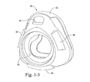
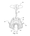
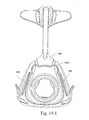
図1−1、図1−2および図2−1〜図2−3に示すように、フレーム20(外骨組または骨組とも呼ぶ)は、患者の顔に対して動作位置で封止機構40(およびエルボー70)を保持し、安定化し、かつ/または支持するように構成されている。さらに、フレーム20は、鼻マスクシステムにヘッドギアを取り付けるように構成されている。
2. 2. Frame As shown in FIGS. 1-1, 1-2 and 2-1 to 2-3, the frame 20 (also referred to as an outer skeleton or skeleton) is a
図示するように、フレーム20の本体22(たとえば、図1−2、図2−2および図2−3参照)は、中心開口部24を備えた開放構造を有し、それにより、封止機構40が、エルボー70、および封止機構40を保持するかまたは他の方法で封止機構40と係合するように構成された側壁26と連通し、またはそれらを受け入れることができる。使用時、この例のフレーム20は空気路にはなく、すなわち、封止機構40は、後述するように呼吸腔(breathing cavity)を画定しかつエルボー70に直接結合される。フレーム20
は、半剛性であってもよく、または少なくとも幾分かの可撓性を可能にすることができる。フレーム20を、単一材料、材料の組合せ、または硬度の異なる同じ材料の組合せから作製することができる。フレーム20を、ポリカーボネート、ポリプロピレン、ナイロン、クリアナイロン、熱可塑性エラストマー(TPE)、シリコーンまたは他の任意の適切な材料から作製することができる。
As shown, the
May be semi-rigid, or at least allow some flexibility. The
額支持体30は、本体22の上端部から延在している。額支持体30は、固定されていてもよく(すなわち調整可能でない)、調整可能であってもよく(たとえば細長いアームの高さまたは長さが伸長可能であり得るか、または額支持体の角度が変更可能であり得る)、または交換可能であってもよい(たとえば、種々のサイズの患者に対して種々のサイズの額支持体、または細長いアームを種々のさまざまな長さのアームと交換することができる)。額支持体30は、細長いアーム32および上部ヘッドギアコネクタ34を有し、上部ヘッドギアコネクタ34は、アームの自由端に、使用時にそれぞれのヘッドギアストラップを受け入れるように適合された溝穴または受け穴35を提供し、したがって別個のパッドを必要とするのではなくヘッドギアストラップの当て物を使用する。一例では、ヘッドギアコネクタは、たとえばアーム32に対して調整可能であり得る(たとえば、患者の額に向かって傾斜するかまたは角度をなすことができる)。本体22のそれぞれの側面に対して下部ヘッドギアコネクタ36が設けられており、各下部ヘッドギア36は、細長いアーム38と、アームの自由端に使用時にそれぞれのヘッドギアストラップを受け入れるように適合された溝穴または受け穴39とを有している。細長いアーム38は、使用時にアームが患者の顔に向かってまたは顔から離れる方向に屈曲することができるように、屈曲可能であるかまたは選択的に変形可能であってもよく、それにより、ヘッドギアを患者の顔の上に引っ張り、たとえば横向きに寝ることが可能になる。一例では、細長いアーム38が、使用者の手の圧力により屈曲可能または変形可能である場合、細長いアームは、変形した形状を保持するように適切に可鍛性があってもよい。細長いアーム38のこの特徴により、本実施形態の快適さ、適合性および/または封止を向上させることができる。額支持体およびヘッドギアコネクタは、患者の視線から外れて延在する邪魔にならない配置を提供することができる。細長いアーム38の概して薄くかつ細長い構造により、実施形態を着用している間、患者の視線に対する障害を少なくとも部分的に防止しまたは制限することができる。一例では、細長いアーム38を、ワイヤまたは金属合金から構成することができる。しかしながら、当業者は、限定されないがたとえばポリマー材料を含む他の材料を用いてもよいことを理解するであろう。
The
一例では、アーム32、38を、患者の視線を回避するかまたは患者の視覚を妨げないようにする一方で、患者の顔の輪郭をたどるように適切に形成し、成形し、または外形を形成することができる。また、アーム32、38は、ある範囲の調整を可能にするように幾分かの固有の可撓性を有することができる。細長いアーム32、38を、アルミニウム、ステンレス鋼、ポリカーボネート、ポリプロピレン、TPEまたは他の任意の適切な材料等の概して非伸縮性の材料から作製することができる。代替的に、細長いアーム32、28は、フレーム20と連続的であってもよく、したがって同じ材料から作製されていてもよく、またはフレーム20と同じ材料から作製されるが単体構造ではなくてもよい(すなわち、細長いアーム32、38をフレーム20に取り付けることができる)。しかしながら、細長いアーム32、38がフレーム20とは異なる材料から作製される場合、細長いアーム32、38を、たとえば接着等、別の取付方法または固定方法を用いてフレーム20に固定することができる。上部ヘッドギアコネクタ34を、細長いアーム32と同じ材料から作製することができる。代替的に、上部ヘッドギアコネクタ34を、Hytrel(商標)、シリコーン、ナイロンまたは他の任意の適切な材料等、細長いアーム32より可撓性の材料から作製してもよい。下部ヘッドギアコネクタ36は、フレーム20と連続していてもよく、したがって、同じ材料から作製されていてもよく、またはフレーム20と同じ材料から作製されるが単体構造でなくてもよい(すなわち、細長いアーム38をフレーム20に取り付けることができる)。代替的に、下部ヘッドギアコネクタ36を、Hytrel(商標)、シリコーン、ナイロンまたは他の任意の適切な材料等、フレーム20より可撓性のある材料から作製してもよい。
In one example, the
額支持体およびヘッドギアコネクタを、フレーム20の本体と一体的に成形してもよく、または他の方法で本体に取り付けてもよい。フレーム20は、封止機構40(たとえばシリコーン、フォームからなる)より剛性の材料から構成されている。たとえば、フレームを、プラスチック(たとえばポリカーボネート)および/または金属材料、たとえば比較的薄い金属材料から構成してもよい。
The forehead support and headgear connector may be integrally molded with the body of the
一例では、アーム32および/または38は、比較的薄いかまたは細長くてもよい(たとえば1mm〜3mm)。一例では、額支持体30およびヘッドギアコネクタ36を、フレーム本体22の材料とは異なる材料(たとえば金属材料)から形成してもよい。こうした例では、額支持体30およびヘッドギアコネクタ36は、フレーム本体22に取付可能であり得る。比較的薄いかまたは細長いアーム32および/または38により、マスクまたは実施形態の全体的な視覚的インパクトを低減することができる。
In one example, the
一例では、上部ヘッドギアコネクタ34は、ヘッドギアからのストラップの取付のために平坦領域を提供する。一例では、ストラップは、上部ヘッドギアコネクタ34の両側に取り付けられた2つの開口部35を通って上部ヘッドギアコネクタ34に取り付けられ、この実施形態では、ストラップは、開口部を通って延在し、患者の顔に向かって力を引き起こし、上部ヘッドギアコネクタ34を患者の額に向かって有効に引っ張るように適合されている。
In one example, the
2.1代替的なフレーム
図5−1〜図5−6は、封止機構440(およびエルボー70)を患者の顔に対して動作位置で維持しまたは他の方法で支持するように構成されているフレーム420の代替実施形態を示す。
2.1 Alternative frame FIGS. 5-1 to 5-6 are configured to maintain the sealing mechanism 440 (and elbow 70) in motion position with respect to the patient's face or otherwise support it. An alternative embodiment of the
フレーム420を、鼻マスクシステムにヘッドギアを取り付けるように構成することができる。フレーム420を、ポリカーボネート、ポリプロピレン、ナイロンまたは他の任意の適切な材料から作製することができる。スイベルリング90が、封止機構440をエルボー70に接続することができる。スイベルリング90は、ポリカーボネートまたはポリプロピレン等の任意の適切なポリマーであり得る。エルボー70は小型かつ邪魔にならないものであり得る。エルボーは、通気のために孔または開口部を備えた通気機構75を有することができる。エルボー70を、ポリプロピレン、ポリカーボネートまたは他の任意の適切な材料から作製することができる。
The
額支持体430は、フレーム420の本体422の上端部から延在している。額支持体430は、固定されていてもよく(すなわち調整可能でない)、調整可能であってもよく(たとえば細長いアームの高さまたは長さが伸長可能であり得るか、または額支持体の角度が変更可能であり得る)、または交換可能であってもよい(たとえば、種々のサイズの患者に対して種々のサイズの額支持体、または細長いアームを種々のさまざまな長さのアームと交換することができる)。額支持体430は、細長いアーム432および上部ヘッドギアコネクタ434を有し、上部ヘッドギアコネクタ434は、アーム432の自由端に、使用時にそれぞれのヘッドギアストラップを受け入れるように適合された溝穴または受け穴435を提供し、したがって別個のパッドを必要とするのではなくヘッドギアストラップの当て物を使用する。一例では、ヘッドギアコネクタ434は、たとえばアーム432に対して調整可能であり得る(たとえば、患者の額に向かって傾斜するかまたは角度をなすことができる)。
The
上部ヘッドギアコネクタ、すなわち額支持体パッド434を、シリコーン、ナイロン、ポリプロピレン、TPE、ポリカーボネートまたは他の任意の適切な材料から作製することができる。細長いアーム432を、可鍛性金属から作製することができる。フレーム420は、細長いアーム432および封止機構440のための接続点であり得る。
The upper headgear connector, ie
フレーム420の本体422のそれぞれの側面に、下部ヘッドギアコネクタ436が設けられている。下部ヘッドギアコネクタ436はフック形状であり得る。下部ヘッドギアコネクタ436を、フレーム420の本体422に一体的に形成してもよく、または本体から別個に形成して、たとえば接着剤または任意の形態の機械的固定によって取り付けてもよい。
各下部ヘッドギアコネクタ436は、コネクタ436の上端部とフレームの本体422との間に間隙439を有することにより、ヘッドギアストラップがそれらの間に挿入されるのを可能にすることができる。ヘッドギアコネクタ436を、下端部および上端部の両方においてフレーム420の本体422に接続してもよいことが理解されるべきである。
コネクタ436は、使用時にコネクタ436が患者の顔に向かってまたは患者の顔から離れる方向に屈曲することができるように、屈曲可能であるかまたは選択的に変形可能であってもよく、それにより、ヘッドギアを患者の顔の上に引っ張り、たとえば横向きに寝ることが可能になる。これにより、鼻マスクシステムの快適さ、適合性および/または封止を向上させることができる。額支持体430およびヘッドギアコネクタ434、436は、患者の視線から外れて延在する邪魔にならない配置を提供することができる。下部ヘッドギアコネクタ436をフレーム420の本体422の下隅位置に配置することにより、鼻マスクシステムを着用している間、患者の視線に対する障害を少なくとも部分的に防止しまたは制限することができる。
Each
The
2.2代替的なフレーム
以下は、マスクシステムに対するフレーム、アームおよび額支持体の代替実施形態を示す。
2.2 Alternative Frames The following show alternative embodiments of frames, arms and forehead supports for mask systems.
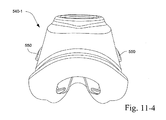
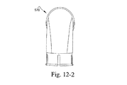
2.2.1フレーム
図7−1〜図7−3は、フレーム520、封止機構またはクッション540、細長いアーム532および額支持体530、エルボー570、ならびにエルボーをクッションに結合するリング590を含む鼻マスクシステムを示す。
2.2.1 Frame Figures 7-1 to 7-3 include a
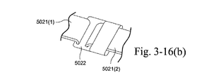
図8−1〜図8−3に最もよく示すように、フレームに設けられた各下部ヘッドギアコネクタ536は略S字型であり得る。各下部ヘッドギアコネクタは、上部分536(1)、中間部分536(2)、下部分536(3)、およびコネクタをフレームに取り付ける接続部分536(4)を有している。上部分536(1)は、ヘッドギアストラップを適所に案内するように適合された引込部を有することができる。中間部分536(2)は、係合されたストラップをコネクタ内で保持するように、フレームに当接するように適合されるかまたはフレームに近接している。下部分536(3)は、中間部分を通るように押し込まれたストラップを受け入れるように適合されている。接続部分536(4)により、コネクタは外側にすなわちフレームから離れる方向にヒンジ運動することができ、それにより、ヘッドギアストラップがコネクタの中間部分とフレームとの間を通ることができる。
As best shown in FIGS. 8-1 to 8-3, each
コネクタ536は、フレームの側面に沿ってヘッドギアを摺動させる際の使用容易性を可能にするように、フレームに近接して位置合せされる。自動閉鎖式コネクタは、ヘッドギアに対する保持機能として依然として作用しながら容易なアクセスを可能にする。
The
一実施形態では、コネクタの1つまたは複数の部分をTPEから構成することができる。 In one embodiment, one or more parts of the connector can be configured from TPE.
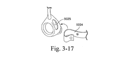
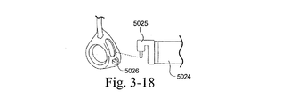
図8−4および図8−5は、代替的な下部ヘッドギアコネクタ、たとえばフック状コネクタ536−1と、自由端がフレームのコネクタ基部520−1と係合するように適合されたコネクタ536−2とを示す。図8−5に示すように、フック状コネクタ536−1の自由端は、ヘッドギアストラップの保持に役立つ保持フックを有している。図8−4に示すように、コネクタ536−2を、ヘッドギアストラップの保持に役立つように、基部520−1と係合するように付勢させることができる。 8-4 and 8-5 show an alternative lower headgear connector, eg, a hook connector 536-1, and a connector 536-2 adapted such that the free end engages the connector base 520-1 of the frame. And. As shown in FIG. 8-5, the free end of the hook-shaped connector 536-1 has a holding hook that helps hold the headgear strap. As shown in FIG. 8-4, the connector 536-2 can be urged to engage the base 520-1 to help hold the headgear strap.
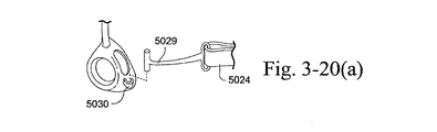
図16−1および図16−2は、クッションおよびヘッドギアを支持するフレーム520−1の別の実施形態(たとえば、下部ヘッドギアストラップ用の下部クロスバー5536と、上部ヘッドギアストラップ用の開口部5537を備えた額支持バーとを備えた開放フレーム構成)を示す。図17−1および図17−2は、クッションおよびヘッドギアを支持するフレーム520−2の別の実施形態を示す(たとえば、ヘッドギアクリップ5540が、フレーム上の棒状のレセプタクル5541と係合するように適合された開口部5440(1)を有する)。フレーム520−2はまた、上述した図16−1および図16−2と同様に上部ヘッドギアストラップ用の開口部を備えた額支持バーも有している。さらに、フレーム520−2は、クッションを支持しかつ/または保持するように適合された上方に延在するクッション支持バー521を有している。
16-1 and 16-2 include another embodiment of the frame 520-1 that supports the cushion and headgear (eg, a
代替実施形態では、フレームは、下部ヘッドギアストラップに関連するそれぞれのヘッドギアクリップと取外し可能に噛み合うように適合されたクリップレセプタクルを有していてもよい。 In an alternative embodiment, the frame may have a clip receptacle fitted to detachably mesh with each headgear clip associated with the lower headgear strap.
2.2.2細長いアーム
フレームは、額支持体を保持する細長いアーム(たとえば、金属、可鍛性金属から構成される)を支持する。
2.2.2 Elongated arm The frame supports an elongated arm (eg, composed of metal, malleable metal) that holds the forehead support.
一実施形態では、図7−1〜図7−3に示すように、金属アーム532は密閉された押出成形品であり得る。図9−1に示すように、アーム532の金属mは、正面において、プラスチック密封体pが金属を覆わないように広くなっていてもよい。こうした密封構成は、金属を柔らかくするとともに保護する柔らかい触感の特徴を提供する。
In one embodiment, as shown in FIGS. 7-1 to 7-3, the
別の実施形態では、図9−2および図9−3に示すように、金属アームは露出した押出成形品(たとえば、研磨された押出アルミニウム)であってもよい。この構成により、金属の特徴が強調され、流線形の邪魔にならない設計が提供される。 In another embodiment, as shown in FIGS. 9-2 and 9-3, the metal arm may be an exposed extruded product (eg, polished extruded aluminum). This configuration emphasizes the characteristics of the metal and provides a streamlined, unobtrusive design.
図9−4は、ポリマーコーティング(シリコーン、TPE等)に密閉されたガラス充填ナイロンから構成されたアーム532を示す。密閉された金属設計を、強化プラスチックの代りに用いることにより、金属の代りに強度を提供し、薄い邪魔にならないアームを容易にすることができる。この構成により、色および仕上げの細部を追加する機会も与えられる。
FIG. 9-4 shows an
2.2.3額支持体
額支持体は、アーム532によって支持されている。図10−1〜図10−5に示すように、額支持体530に、可撓性領域531を組み込むことができ、それにより額支持体530は、その自然なv字型の位置または形状からより直線状の位置または形状に撓むことができる。可撓性領域は、額支持体530の残りの部分と比較した場合に、材料の薄化部分(すなわち、額支持体の残りと同じ材料であり、単に撓曲を可能にするために薄い)であるか、より軟質なより剛性でない材料であるか、またはより軟質な材料と薄い部分との組合せであり得る。
2.2.3 Forehead support The forehead support is supported by the
可撓性領域は、熱可塑性エラストマー(着色されていてもよい)、シリコーン、または撓曲することができる他の任意の材料等、可撓性材料の共成形部分であってもよい。額支持体の残りの部分を、ナイロン、ポリカーボネートまたはポリプロピレン等のより可撓性でない材料から作製してもよい。共成形は、2つの材料の間の化学的接合および/または機械的接合を介してもよい。別個に形成され/組み立てられた可撓性領域により、破損の危険が低減し、現場外でのヘッドギアとの組立てが可能になる。額支持体は、艶消し仕上げを有していてもよい。 The flexible region may be a co-molded portion of the flexible material, such as a thermoplastic elastomer (which may be colored), silicone, or any other material that can be flexed. The rest of the forehead support may be made from a less flexible material such as nylon, polycarbonate or polypropylene. Comolding may be via chemical or mechanical bonding between the two materials. The separately formed / assembled flexible area reduces the risk of breakage and allows for off-site assembly with headgear. The forehead support may have a matte finish.
一実施形態では、額支持体530をまず平坦に成形してもよい。そして、可撓性領域531を額支持体530の上に成形し、額支持体530をその使用時のまたは撓曲した形状に配置してもよい。これにより、額支持体に予荷重するかまたはバイアスまたはばねを提供することができる。
In one embodiment, the
可撓性領域は自動調整撓曲機能を提供し、それは、適合性に役立つようにクッションのより大きい付勢を可能にするヘッドギアの張力によって調整される。好ましくは、額支持体は、マスククッションの上部を患者の鼻梁領域の内側にかつ外側に傾斜させるかまたは回転させるように撓曲することができる。一形態では、ヘッドギアストラップが締め付けられると、額支持体は、外側に広がるかまたは患者の額に対して平坦になることができる。これにより、マスククッションが傾斜または回転し、マスククッションの下部がヒンジ点として作用する。このため、マスククッションの上部は、患者の顔の平面に対して略垂直な方向に、患者の鼻梁に向かって内側に傾斜または回転することができる。これは、他の患者より鼻梁の高い患者に有用である可能性があり、それは、これにより、マスククッションの鼻梁領域が患者の鼻と封止係合するように付勢されるためである。 The flexible region provides an auto-adjustable flexure feature, which is adjusted by the tension of the headgear, which allows for greater urgency of the cushion to aid in compatibility. Preferably, the forehead support can be flexed so that the upper part of the mask cushion is tilted or rotated inward and outward in the patient's nasal bridge area. In one form, when the headgear straps are tightened, the forehead support can spread outward or flatten against the patient's forehead. This causes the mask cushion to tilt or rotate, and the lower part of the mask cushion acts as a hinge point. Therefore, the upper part of the mask cushion can be tilted or rotated inward toward the patient's nasal bridge in a direction substantially perpendicular to the plane of the patient's face. This may be useful for patients with a higher nasal bridge than other patients, as this urges the nasal bridge region of the mask cushion to engage the patient's nose in a sealed manner.
代替的に、額支持体を、圧縮されることにより同様の結果を達成することができる、フォーム等の厚化された柔軟な材料から作製することができる。 Alternatively, the forehead support can be made from a thickened flexible material such as foam, which can achieve similar results by being compressed.
図10−2に示すように、いかなる負荷もない(すなわち自然な状態の)額支持体の位置を、角度αとして明示することができ、たとえば角度αは5°〜90°、たとえば15°であり得る。 As shown in FIG. 10-2, the position of the forehead support without any load (ie, in its natural state) can be specified as an angle α, for example the angle α is between 5 ° and 90 °, for example 15 °. possible.
使用時、額支持体は、(図10−2および図10−4における矢印によって示すような)前後方向に約0mm〜30mmの調整を可能にすることができる。例示的な実施形態では、額支持体は、前後方向に約5mm〜20mm(たとえば約10mm〜20mm、約10mm〜15mm)の調整を可能にすることができる。これにより、特に鼻梁領域における、より多種多様な人体測定学に適応することができるため、より広範囲の患者の適合性を可能にすることができる。 In use, the forehead support can allow an adjustment of about 0 mm to 30 mm in the anteroposterior direction (as indicated by the arrows in FIGS. 10-2 and 10-4). In an exemplary embodiment, the forehead support can allow adjustments of about 5 mm to 20 mm (eg, about 10 mm to 20 mm, about 10 mm to 15 mm) in the anteroposterior direction. This makes it possible to adapt to a wider variety of anthropometry, especially in the nasal bridge region, thus allowing for a wider range of patient compatibility.
ヘッドギアを、ループ穴535(たとえば図10−1および図10−3参照)を通して額支持体に取り付けることができ、または溝穴535−1が穴535(図10−6参照)内に延在する、ループスルー構成を介して取り付けることができる。 Headgear can be attached to the forehead support through loop holes 535 (see, eg, FIGS. 10-1 and 10-3), or groove holes 535-1 extend into holes 535 (see FIGS. 10-6). , Can be installed via a loop-through configuration.
2.3額支持体の代替実施形態
図20−1(a)〜図26は、額支持体の代替実施形態を示す。
2.3 Alternative embodiments of the forehead support FIGS. 20-1 (a) to 26 show alternative embodiments of the forehead support.
額支持体の利点のうちの1つは、額支持体が、多数の追加の構成要素なしに妥当な量の調整を提供するということである。好ましい例では、額支持体はすべて一体的に成形される。さらに、額領域においてヘッドギアストラップを患者の頭の後部に向かって引っ張ることにより、クッションが直観的に移動し、鼻梁に向かって回転し、その領域における漏れを低減しかつなくす可能性がある。 One of the advantages of the forehead support is that the forehead support provides a reasonable amount of adjustment without a number of additional components. In a preferred example, the forehead supports are all integrally molded. In addition, by pulling the headgear strap towards the back of the patient's head in the forehead area, the cushion may move intuitively and rotate towards the nasal bridge, reducing or eliminating leaks in that area.
本技術の例によれば、鼻クッションおよびフレームを有するマスクシステムが提供される。フレームは、T字バーを有する額支持体を有している。T字バーは、主軸およびクロスバーを有している。一形態では、クロスバーは左側および右側を有している。 According to an example of the present art, a mask system with a nasal cushion and a frame is provided. The frame has a forehead support with a T-bar. The T-bar has a spindle and a crossbar. In one form, the crossbar has left and right sides.
本技術の態様によるマスクシステムはヘッドギアを有している。一形態では、ヘッドギアは左額ストラップおよび右額ストラップを有している。左額ストラップおよび右額ストラップは、頂点から末端の位置において、使用時にクロスバーのそれぞれ左側および右側と係合するように構成されかつ配置されている。 The mask system according to the aspect of the present technology has a headgear. In one form, the headgear has a left forehead strap and a right forehead strap. The left and right forehead straps are configured and arranged to engage the left and right sides of the crossbar in use, respectively, at the apex to end positions.
一形態では、左側部および右側部は、互いに約180°未満の角度で配置されている。この形態では、クロスバーは平面図においてV字型であってもよい。頂点は、左側と右側との間に画定されている。一形態では、左側および右側は、頂点を中心に屈曲または撓曲するように構成されかつ配置されている。一形態では、両側をそれらの末端で引っ張ることによって屈曲または撓曲させることにより、それらの間の角度が増大し、クロスバーと主軸との接触点が額により近接するように移動し、クッションを回転させる。 In one embodiment, the left and right sides are arranged at an angle of less than about 180 ° to each other. In this form, the crossbar may be V-shaped in plan view. The vertices are defined between the left and right sides. In one form, the left and right sides are configured and arranged to bend or flex around the apex. In one form, bending or flexing by pulling on both sides at their ends increases the angle between them, moving the contact point between the crossbar and the spindle closer to the forehead, and the cushion. Rotate.
代替形態では、クロスバーの左側および右側はU字型であってもよい。このU字型では、クロスバーは、上述したV字型形態と同様の機能を有することができる。 In the alternative form, the left and right sides of the crossbar may be U-shaped. In this U-shape, the crossbar can have the same function as the V-shaped form described above.
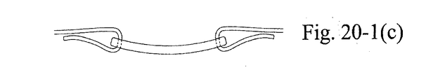
たとえば、図20−1(a)〜図20−1(c)および図20−2(a)〜図20−2(c)は、各々、ヘッドギアストラップ1080からのヘッドギアの張力がクロスバーのそれぞれの側に加えられる際に、頂点を中心として屈曲または撓曲するように構成された略U字型クロスバー1034の連続した図を示す。図示するように、額支持体は、患者の額の前方の拡張位置で開始する。患者がヘッドギアを締め付ける(すなわち、矢印によって示すように、ヘッドギアストラップがクロスバーから外側に引っ張られる)と、クロスバーの両側が開放するように広がるかまたは外側に撓曲し、クロスバーは、患者の額の実質的に平坦な位置まで移動し、それによりクッションを患者の顔に向かって内側に付勢することができる。クロスバーにおけるそれぞれのヘッドギアストラップ用の溝穴1035を、頂点から外側に比較的遠くに(たとえば、図20−2(c)に示すような距離d)配置することにより、ベクトルを増大することができる(たとえば、有効な力で患者の頭に向かって額支持体を引っ張るために必要な力が低減する)。
For example, in FIGS. 20-1 (a) to 20-1 (c) and FIGS. 20-2 (a) to 20-2 (c), the tension of the headgear from the
中央部分が薄い材料からクロスバーを成形することにより、屈曲または撓曲を達成することができる。このように、クロスバーは、その両端より中央部がより可撓性を有することができる。さらにまたは代替的に、クロスバーを、より剛性の材料(たとえばナイロン等)をより可撓性の材料(たとえば、熱可塑性エラストマー)と共成形することによって形成することができる。 Flexures or flexures can be achieved by molding the crossbar from a material with a thin central part. In this way, the crossbar can be more flexible at the center than at both ends. Further or alternative, the crossbar can be formed by co-molding a more rigid material (eg, nylon, etc.) with a more flexible material (eg, a thermoplastic elastomer).
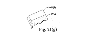
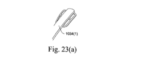
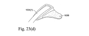
たとえば、図20−1(a)〜図20−1(c)および図20−2(a)〜図20−2(c)に示すように、クロスバーは、より可撓性の材料(たとえば、可撓性TPEまたはシリコーン)から構成される中間部1034(1)と、より剛性の材料(たとえばクリアナイロン)から構成される端部または側部1034(2)とを有することができる。 For example, as shown in FIGS. 20-1 (a) to 20-1 (c) and FIGS. 20-2 (a) to 20-2 (c), the crossbar is a more flexible material (eg,). , Flexible TPE or silicone), and an end or side 1034 (2) made of a more rigid material (eg, clear nylon).
図21(a)〜図23(e)は、額支持体およびそのクロスバーの代替構成を示す。たとえば、図21(a)〜図21(G)は、可撓性領域1036がより剛性な領域、すなわちクロスバーの中間部1034(1)とそれぞれの側部1034(2)との間に配置されている、額支持体を示す。可撓性領域1036は、より可撓性の材料(たとえばHytrel(登録商標))から構成され、中間部1034(1)および側部1034(2)はより剛性の材料(たとえばナイロン)から構成されている。図示するように、可撓性領域をより剛性の領域に埋め込むことができる。また、可撓性領域は、より剛性の領域と、保持機能、たとえば蟻継ぎの噛合いによって噛み合わせることができる。図22(a)〜図22(h)および図23(a)〜図23(e)は、可撓性領域1036をより剛性の領域1034(1)、1034(2)と噛み合わせるかまたは結合する代替構成を示す。図23(a)〜図23(e)において、可撓性領域はクロスバーの側部を組み込んでいる。
21 (a) to 23 (e) show alternative configurations of the forehead support and its crossbar. For example, FIGS. 21 (a) to 21 (G) indicate that the
額支持体およびヘッドギアは、左額ストラップおよび/または右額ストラップを引っ張ることにより、主軸が移動してクッションを回転させるように構成されかつ配置されている。このように、マスクの適合を、種々の顔形状に対して調整することができる。たとえば、ストラップを引くことによりクッションが顔に向かって回転することができ、鼻梁領域における漏れが低減する。 The forehead support and headgear are configured and arranged so that the spindle moves to rotate the cushion by pulling on the left forehead strap and / or the right forehead strap. In this way, the fit of the mask can be adjusted for various face shapes. For example, pulling the strap allows the cushion to rotate towards the face, reducing leakage in the nasal bridge area.
図24(a)および図24(b)は、クロスバーの各側が弾性ばねアーム1037を有する額支持体を示す。図示するように、ヘッドギアストラップ1080は、ばねアームの周囲にループを形成するように適合され、それによりヘッドギアストラップは、患者の額を、クロスバーとヘッドギアストラップとの間に配置されたばねアームと係合させる。使用時、ヘッドギアの張力により、ばねアームが屈曲または撓曲し、額支持体の接触点が患者の額により近接するように移動することができる。
24 (a) and 24 (b) show a forehead support with
図25および図26は、フォームまたはゲル等の柔軟な材料から構成された額パッド1090を有する額支持体を示す。図25に示すように、額パッドを、スナップ嵌合によってクロスバー1034に結合することができ、たとえば、額パッド1090は、クロスバーのそれぞれの開口部1038とスナップ嵌合によって係合するように適合されたスナップ指部1091を有している。クロスバーの両側は、ヘッドギアストラップと係合するように適合された、端部が開放した溝穴を有している。図26に示すように、ヘッドギアストラップ1080は、クロスバー1034とその額パッド109とを横切ることができ、それにより、患者の額を、クロスバーとヘッドギアストラップとの間に配置された額パッドと係合させる。
25 and 26 show a forehead support with a
2.4さらなる代替的なフレーム実施形態
クッションを適所で安定化し、クッションを適所に保持するようにヘッドギアを係留するように、システムにフレームを設けることができる。フレームは、クッションに構造または支持をさらに追加することができる。
2.4 Further Alternative Frame Embodiments The system can be provided with a frame to stabilize the cushion in place and moor the headgear to hold the cushion in place. The frame can add additional structure or support to the cushion.
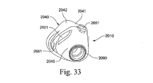
図27〜図32に示す代替的なフレーム2020は、本体2100、額支持アーム2400および額支持パッド2530を備えている。
The
本体2100を、クッションおよび下部ヘッドギアストラップを捕捉しまたはそれと係合するように構成することができる。上部領域2700が、マスククッションの頂部領域または頂点領域と係合する。上部領域2700を、マスクフレーム2020の非患者側の本体2100の上位部すなわち頂部に配置することができる。上部領域2700はまた、クッションのこの領域に剛性または支持を追加することにより、クッションの正面すなわちエルボー係合部に安定性を提供することができる。下部領域2800を、上部領域の概して下位に配置することができる。下部領域2800は、マスククッションの底部領域と係合するかまたは他の方法でインタフェースすることができる。
The
後部コネクタまたは係合部2650(図29および図32参照)を、マスククッションのタブまたは係止要素を受け入れるように構成することができる。後部係合部2650はまた、マスクフレーム2020内におけるマスククッションの位置特定に役立つことも可能である。後部係合部2650は切取部または開口部であってもよい。後部コネクタ2650を、フレーム2020の患者側に配置することができる。
The rear connector or engaging portion 2650 (see FIGS. 29 and 32) can be configured to accommodate the tabs or locking elements of the mask cushion. The
下部ヘッドギアコネクタ2520を、ヘッドギアのループを受け入れるように配置することができる。下部ヘッドギアコネクタ2520は、ヘッドギアストラップを受け入れそれを適所に維持するように、略フック状またはC字型であってもよい。下部ヘッドギアコネクタ2520を、接続部2525により本体2100に取り付けるかまたは他の方法で本体2100とともに形成することができる。接続部2525により、幾分かの可撓性またはヒンジ運動が、下部ヘッドギアコネクタ2520の幾分かの移動の自由を可能にすることができる。
The
下部ヘッドギアコネクタ2520を、限定されないがたとえば、シリコーン、TPEまたは他の任意の適切な材料を含む可撓性材料から形成することができる。下部ヘッドギアコネクタを、形状を保持しヘッドギア力をマスクに伝達するようにより剛性の材料、およびヘッドギアストラップの容易な係合および分離を可能にするようにより可撓性の材料等、材料の組合せから形成することができる。これには、ナイロンおよびシリコーン等の材料の組合せを挙げることができる。可撓性材料はまた、ヘッドギアがコネクタ内で摺動しないように、材料に対する粘着力または摩擦力を有していてもよい。これには、限定されないがシリコーンを挙げることができる。好ましくは、下部ヘッドギアコネクタへのヘッドギアの組立てには、ヘッドギアを下部ヘッドギアコネクタから分解するより必要な力が小さい。好ましくは、分解力は15N未満である。より好ましくは、分解力は10N未満である。
The
図70は、下部ヘッドギアコネクタ2520の代替的な図を示す。図示するように、略フック状またはC字型の下部ヘッドギアコネクタ2520(より可撓性の材料、たとえばシリコーンから構成される)は、本体2100の本体接続部2525(たとえばより剛性の材料、たとえばナイロンから構成される)とオーバモールドまたは共成形される。好ましくは、可撓性材料はシリコーンであり得る。好ましくは、可撓性材料は、ショアAデュロメータが約20〜80であり得る。最も好ましくは、可撓性材料は、ショアAデュロメータが約40〜60であり得る。最も好ましくは、可撓性材料は、ショアAデュロメータが約60であり得る。接続部2525は、コネクタ2520の接続部2525への成形に役立つ接続部分2526を有している。接続部分2526は、オーバモールドされた可撓性コネクタ2520のより剛性の接続部2525との噛合いまたは機械的係止に役立つ保持溝穴2526(1)を有している。また、接続部分2526は、コネクタにおけるヘッドギア接続を強化するために、コネクタ2520の高さまたは頂部まで実質的に延在しており、すなわち、接続部分のより剛性の材料は、ヘッドギアがコネクタから滑り落ちないようにコネクタの形状を保持し、ヘッドギア力をマスクに伝達する。可撓性のコネクタ2520はまた、ストラップのコネクタからのより容易な取外しと、ストラップのコネクタ、たとえばストラップの取外しおよび接続を容易にするように変形可能なコネクタへのより容易な接続を可能にする。
FIG. 70 shows an alternative view of the
図89に示すように、下部ヘッドギアコネクタは、ヘッドギアストラップの保持に役立ちかつ不注意の除去を防止するために、互いに対して角度α1で角度が付けられている内面2521(1)、2521(2)を提供することができる。好ましくは、α1は180°未満であり得る。好ましくは、α1は約110°〜160°であり得る。最も好ましくは、α1は約120°〜150°であり得る。また、フレームの本体からのコネクタの間隔もまた、ストラップの保持に役立つ。好ましくは、本体からのコネクタの間隔は、コネクタの長さに沿って変化することができる。好ましくは、コネクタと本体との間の最も広い間隙は、ストラップの保持に役立つように15mm未満であり得る。より好ましくは、コネクタと本体との間の最も広い間隙は、ストラップの保持に役立つように10mm未満であり得る。 As shown in FIG. 89, the lower headgear connectors are inner surfaces 2521 (1), 2521 (2) angled at an angle α1 with respect to each other to help hold the headgear straps and prevent inadvertent removal. ) Can be provided. Preferably α1 can be less than 180 °. Preferably, α1 can be from about 110 ° to 160 °. Most preferably, α1 can be from about 120 ° to 150 °. The distance of the connector from the body of the frame also helps hold the strap. Preferably, the distance of the connector from the body can vary along the length of the connector. Preferably, the widest gap between the connector and the body can be less than 15 mm to help hold the strap. More preferably, the widest gap between the connector and the body can be less than 10 mm to help hold the strap.
図41〜図44に示すように、マスククッションとインタフェースしかつそれを支持するために、主要部分2100の側方フランジとマスクフレームの患者側とに側部係合タブ2600を配置することができる。一実施形態では、タブは、アンダークッションが鼻梁領域で終端する場所に隣接して配置される。タブは、クッションの一部と締まり嵌めを形成することができる。タブは、フレームの残りの部分または周囲の部分より薄くてもよい。タブはまた、患者の鼻の側面または頬領域と封止係合して支持されるように、クッションを支持することも可能である。タブ2600は、可撓性クッションに対し、それが患者の顔から離れる方向に崩壊する(たとえば破裂)、したがって使用時に封止を破断する可能性がないように、構造的支持を提供する。タブ2600は、図43に示すように、アーム2400から後方に延在することができる。
As shown in FIGS. 41-44,
額支持アーム2400は、本体2100から額パッド2530まで延在する。好ましくは、額支持アーム2400は、患者の視覚を妨げないように薄く(たとえば、1mm〜5mm、10mm未満、または約1mm〜5mm)、マスクを適所に支持するように、構造的に安定しているかまたは比較的非伸縮性である。
The
額支持パッド2530は、上部ヘッドギアストラップと係合する上部ヘッドギアコネクタ2535を有することができる。額支持パッドは、使用時に額支持パッドの患者の額からの距離を調整するための可撓性領域2540をさらに有することができる。不快をもたらすことなく上部ヘッドギアストラップを正常な引張範囲で締め付けるかまたは調整することにより、可撓性領域2540は、額支持パッドを患者の額により近接するように引くために平坦化することができる。そして、これにより、本体は患者の鼻梁に向かって内側に傾斜し、それにより、使用時にマスククッションを患者の鼻梁の上にさらに押し付ける。一実施形態では、可撓性領域を平坦化する力は、約1N〜8Nの範囲であり得る。好ましくは、可撓性領域を平坦化する力は、約2N〜6Nの範囲であり得る。最も好ましくは、可撓性領域を平坦化する力は約2N〜4Nの範囲であり得る。
The
図66〜図69は、額支持アーム2400および額支持パッド2530の代替的な図を示す。図示するように、額支持パッド2530は、上部ヘッドギアコネクタ2535(たとえば、より剛性の材料、たとえばナイロンから構成される)と、可撓性領域2540(より可撓性の材料、たとえばシリコーンから構成される)とを有している。可撓性領域は、ヘッドギアコネクタおよび支持アームを相互接続し、使用時の額支持体の患者の額からの距離を調整するために額支持体に可撓性を提供するように、上部ヘッドギアコネクタ2535および支持アーム2400(たとえばより剛性な材料、たとえばナイロンから構成される)とオーバモールドされる。
66-69 show alternative views of the
各上部ヘッドギアコネクタ2535は、ヘッドギアを取り付けるためのループ穴2536と、可撓性領域をヘッドギアコネクタに対して成形するのに役立つ接続部分2538とを有している。図示するように、溝穴2536−1は、ループスルー構成を提供するように、穴2536内に延在している。支持アームは、可撓性領域を支持アームに対して成形するのに役立つ接続部分2402を有している。接続部分2538、2402は、オーバモールドされたシリコーン製の可撓性領域2540のナイロン製のヘッドギアコネクタ2535および支持アーム2400との噛合いまたは機械的係止に役立つように、それぞれの保持溝穴2538(1)、2402(2)を各々有している。また、図67に示すように、シリコーン製の可撓性領域2540は、ナイロン製の支持アーム2400の各側部の方が、噛合いを強化するように十分厚い(たとえば、各側部では0.5mm以上の厚さ、たとえば各側部は0.8mm厚い)。一実施形態では、可撓性領域は、中間においてアーム2400の周囲でより厚く、コネクタ2535に向かって先細りになっていてもよい。
Each
図66および図68に示すように、ヘッドギアコネクタ2535および支持アーム2400は、シリコーン製の可撓性領域2540と成形するのに役立ち、かつフレームに対するばりおよび損傷を防止する機能を有することができる。たとえば、支持アーム2400は、ナイロン製のアーム上でシリコーン製の可撓性領域を成形するのに役立つようにリップ2404を有していてもよい。また、各ヘッドギアコネクタ2535は、ナイロン製のヘッドギアコネクタの上でシリコーン製の可撓性領域を成形するのに役立つように丸い壁2539(たとえば、約0.2mm〜0.6mm高さ、たとえば0.4mm高さ)を有することができる。一実施形態では、壁2539は、成形型に配置されると部品から粉砕されるクラッシュビードであってもよい。
As shown in FIGS. 66 and 68, the
好ましい実施形態では、ヘッドギアコネクタ2535およびアーム2400は、互いから別々に形成され(たとえば3つの別個の部品)、その後、可撓性領域2540によって互いに接続される。代替実施形態では、図69に示すように、ヘッドギアコネクタ2535を、ランナ2555によってアーム2400に接続し(たとえばヘッドギアコネクタおよびアームを一部品として形成する)、その後、可撓性領域とオーバモールドしてもよい。
In a preferred embodiment, the
代替実施形態では、ヘッドギアコネクタ2535は、上述した下部ヘッドギアコネクタ2520等のシリコーン製のコネクタを含むことができる。
In an alternative embodiment, the
図88〜図93は、フレーム2020およびその額支持アーム2400、上部ヘッドギアコネクタ2535、可撓性領域2540および下部ヘッドギアコネクタ2520のさまざまな図を示す。一実施形態では、図91に示すように、コネクタ2535の間の角度は、約100°〜170°、たとえば125°〜145°であってもよい。図94〜図98は、図71〜図87のクッション6540と係合される図88〜図93のフレーム2020を示す。
88-93 show various views of the
3.封止機構
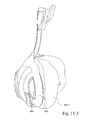
封止機構40は、フレーム20とインタフェースし、使用時に患者の鼻と封止を形成するように構成されている。この例では、封止機構40は、患者の顔の鼻梁領域、頬領域および上唇領域に概して沿って患者の顔に係合するように適合された鼻インタフェースを提供する。しかしながら、他のインタフェース、たとえばフルフェースも可能である。封止機構は、比較的迅速に封止し使用時に封止を維持するように適合された柔軟な構成を提供する。一例では、封止機構を、空気圧でまたは空気圧なしで封止するように構成することができる。
3. 3. Sealing Mechanism The
3.1シリコーンクッション
図1−1〜図1−4の例では、封止機構40は、限定されないがシリコーン、TPE、ゲルまたは他の材料を含む略可撓性材料から構成されるクッション42を有している。クッションを、タイプAデュロメータが約35〜約45、たとえば約37〜約42、好ましくは約40である材料で成形することができる。クッション42は、患者の鼻を受け入れるとともに患者への空気連通を提供するように適合された呼吸室または呼吸腔を画定する。
3.1 Silicone Cushion In the example of FIGS. 1-1 to 1-4, the
クッション42の顔接触側は、二重壁構造を有し、そこでは、クッションは、アンダークッション44と、少なくとも部分的にアンダークッション44を覆う膜46(たとえば図1−4参照)とを有している。膜は、概して、アンダークッションより軟質でありかつより剛性が小さく、使用時に患者の顔に対して封止を提供する。アンダークッションは、概して膜を支持し、鼻マスクシステムがヘッドギアを用いて取り付けられかつ締め付けられる時に膜の崩壊を防止するように構成されている。一例では、アンダークッションを、マスクシステムの選択された領域、たとえば頬領域に沿ってのみ設けてもよく、またはまったく設けなくてもよい。また、クッションを、たとえば容易な適合および快適さのために艶消しにしてもよく、かつ/または着色してもよい。
The face contact side of the
図1−4は、クッション42の顔接触側の頬領域の断面を示す。図示するように、クッションは、基部60と基部60の外側に向かって半径方向に角度をなしている上部62を備えた、鎌形または疑問符形態を含み、それにより、たとえば、サイズおよび知覚される嵩を低減し、呼吸腔内のデッドスペースを最小限にし、かつ/または使用時にアンダークッションおよび膜により可撓性を加える。こうした断面を、クッションの周縁全体に設けてもよく、またはクッションの選択された領域にのみ設けてもよい。一例では、たとえばクッションが患者の口内に張り出すのを回避し鼻孔閉塞を防止するために、上唇領域における「疑問符」型断面が小さい曲率を有していてもよい。
FIG. 1-4 shows a cross section of the cheek region on the face contact side of the
一例では、膜46とアンダークッション44との間の間隙または間隔45(たとえば図1−4参照)を、たとえばしわおよび漏れを低減するように調整することができる。たとえば、間隙は、膜がアンダークッションの形状に密接に従うように比較的小さくてもよい。一例では、クッションを、間隙がより大きいように成形することができるが、膜は、成形の後にアンダークッションにより近接してヒンジ運動するように予荷重される。別の例では、膜をアンダークッションにより近接するように付勢するために、膜とともに(図1−4において破線で示すような)ベローズ64を設けるかまたは成形してもよい。
In one example, the gap or spacing 45 between the
クッション42の非顔接触側またはフレーム側は、フレーム20にインタフェースするかまたは他の方法で取外し可能に接続するように適合された1つまたは複数のインタフェース構造を有している。図示する例では、クッション42は、たとえばその側面および底面に沿って、フレーム20の側壁26に沿ったそれぞれの開口部27と係合しまたは噛み合うように適合された1つまたは複数の細長いかつ間隔が開けられた突起50を有している。図1−1および図2−1に示すように、こうした構成は、使用者が接続を視覚的に見ることができ、任意に、適切な接続によって可聴クリック音をもたらすことができるため、接続が確立されたという積極的な強化を提供することができる。さらに、クッション42は、その頂部に沿って、たとえば位置合せを支援しさらには位置合せ誤りを防止するために、フレーム側壁26の内側(図示せず)に沿ってビードまたは留め具と係合するかまたは噛み合うように適合された、切欠きまたは戻り止め52を有している。しかしながら、クッションを、他の適切な方法でフレームに接続するかまたは噛み合わせてもよいことが理解されるべきである。
The non-face contact or frame side of the
たとえば、クッション42をフレーム20に接続するあり得る構成は、開示内容がすべて参照により本明細書に組み込まれている特許文献1に開示されている。
For example, a possible configuration for connecting the
クッション42の非顔接触側はまた、後述するようにエルボー70を受け入れるかまたは他の方法でエルボー70と連通するように適合された開口部55も有している。
The non-face contact side of the
図1−5〜図1−12は、上述しかつ同様の参照符号で示されているクッション42に実質的に類似するクッションを示す。対照的に、図1−5〜図1−12のクッションは、その頂部に沿って切欠きまたは戻り止めを有していない。
FIGS. 1-5 to 1-12 show a cushion that is substantially similar to the
図示するように、クッションの顔接触側(すなわち、膜46およびアンダークッション44を有する側)を、クッションの非顔接触側(すなわち、開口部55および呼吸腔を画定する側)と共成形するか、または別個に形成して非顔接触側に取り付けてもよい。好ましくは、クッションの顔接触側およびクッションの非顔接触側は、単一構成要素として形成される。好ましくは、この単一構成要素を、限定されないがシリコーンを含む、患者の皮膚と接触する場合に比較的生体適合性である可撓性封止材料から作製することができる。
As shown, whether the face contact side of the cushion (ie, the side with the
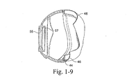
図1−9〜図1−12は、クッションのさまざまな断面図を示す。図1〜図9に示すように、クッションは、クッションの鼻梁領域にアンダークッションを有していなくてもよい。また、図1−9に示すように、上唇領域における膜およびアンダークッションの曲率および/または長さは、適合範囲、快適さのために、かつ外鼻孔の閉塞を防止するように選択される。対照的に、鼻梁領域における膜の曲率および/または長さは、たとえば封止安定性および適合範囲を増大させるために、上唇領域より平坦かつ長くてもよい。これは、クッションが、高い鼻梁およびより平坦な鼻梁を含む種々の鼻梁高さに対して適応しなければならず、したがって、鼻梁領域においてより長い膜が必要であるためである。より高い可撓性を可能とし、鼻梁である敏感な領域に与える力を小さくするために、鼻梁領域にアンダークッションはない。上唇領域における患者の人体測定学的ばらつきは小さく、それにより膜の長さは鼻梁領域より短くなる。患者の顔の適所においてクッションを安定化するのに役立つために、上唇領域にアンダークッションが設けられる。 1-9 to 1-12 show various cross-sectional views of the cushion. As shown in FIGS. 1-9, the cushion may not have an undercushion in the nasal bridge region of the cushion. Also, as shown in Figure 1-9, the curvature and / or length of the membrane and undercushion in the upper lip region is selected for fitness, comfort, and to prevent obstruction of the external nostrils. In contrast, the curvature and / or length of the membrane in the nasal bridge region may be flatter and longer than the upper lip region, for example to increase sealing stability and coverage. This is because the cushion must adapt to various nasal bridge heights, including higher nasal bridges and flatter nasal bridges, and therefore requires a longer membrane in the nasal bridge region. There is no undercushion in the nasal bridge area to allow for greater flexibility and reduce the force exerted on the sensitive area of the nasal bridge. The patient's anthropometric variability in the upper lip region is small, so that the length of the membrane is shorter than in the nasal bridge region. An undercushion is provided in the upper lip area to help stabilize the cushion in place on the patient's face.
図1−11および図1−12は、クッションの顔接触側の頬領域を通る鎌形または疑問符形態を明らかに示すが、図1−9および図1−10は、こうした形態が実質的にない上唇領域を示す。鎌形は、患者の顔の人体測定学的ばらつきに適応するようにクッションのより高い可撓性を可能にするために、頬領域に必要である。たとえば、患者によっては、略平坦な顔を有しており、そのため、クッションが、その実質的に湾曲した輪郭からより平坦な輪郭まで撓曲する必要がある可能性がある。頬領域は、内側にまたは下方に撓曲することが必要となる。代替的に、より角張っているかまたは後方に大きい曲線を描く(swept back)頬を有する患者の場合、クッションの撓曲はそれほど必要ではない可能性がある。両方のシナリオにおいて、患者は、およそ同じレベルの快適さ、したがってクッションから顔におよそ同じレベルの力を受けなければならない。鎌形の追加の可撓性により、患者の顔に対しておよそ同じ力のフィードバックでクッションのある範囲の撓みが可能になる。 1-11 and 1-12 clearly show a sickle or question mark morphology through the buccal area on the face contact side of the cushion, while FIGS. 1-9 and 1-10 show the upper lip in which such morphology is substantially absent. Indicates the area. A sickle shape is needed in the buccal area to allow for greater flexibility of the cushion to adapt to anthropometric variability of the patient's face. For example, some patients have a substantially flat face, which may require the cushion to flex from its substantially curved contour to a flatter contour. The buccal area needs to flex inwardly or downwardly. Alternatively, for patients with more angular or swept back cheeks, cushion flexure may not be as necessary. In both scenarios, the patient must receive approximately the same level of comfort, and thus approximately the same level of force from the cushion to the face. The additional flexibility of the sickle shape allows for some range of flexure of the cushion with approximately the same force feedback to the patient's face.
さらに、使用時にエルボーに対して封止するために、開口部55から内側にリップシール57を設けることができる。
In addition, a
3.2シリコーン膜を備えたフォームクッション
図2−1、図2−2および図2−4〜図2−8に示すような代替例では、封止機構40は、フォームクッション241およびシリコーンクッションまたは膜242を有することができる。
3.2 Foam cushion with silicone membrane In alternative examples as shown in FIGS. 2-1 and 2-2 and FIGS. 2-4 to 2-8, the
シリコーンクッション242は、呼吸腔を画定し、フォームクッション241を支持するかまたは他の方法で保持するように適合されている。図2−6に最もよく示すように、シリコーンクッション242の顔接触側は、アンダークッション244および膜246を含む二重壁構造を提供する。シリコーンクッション242の非顔接触側は、エルボー70を受け入れるかまたは他の方法でエルボー70と連通するように適合された開口部255を有している。
The
アンダークッション244およびアンダークッション244から延在する隣接する側壁247は、フォームクッション241を保持するように構成されている。アンダークッション244は、側壁247から外側にかつ呼吸腔から離れる方向に湾曲して溝248を提供し、溝248は、呼吸腔内に内側に湾曲する膜246と対向している。図示するように、フォームクッション241の少なくとも患者側は、フォームクッション241の内側面が側壁247によって支持されて、アンダークッション244によって画定される溝248(たとえば図2−2および図2−6参照)に挿入される。フォームクッション241を、シリコーンクッション242との締まり嵌めおよび/または摩擦嵌合によって適所に保持することができる。フォームクッション241は、膜246の下にかつアンダークッション244内に配置されるが、空気路または呼吸腔には配置されない。使用時、フォームクッション241は、たとえばシリコーン膜の頬領域に沿って、アンダークッション244に加えられる力を吸収することができる。
The
フォームクッション241の非患者側は、フォームクッション241、したがってシリコーンクッション242をフレーム20で支持する。図示するように、フォームクッション241は、フレームとインタフェースするかまたは他の方法で取外し可能に接続するように適合された1つまたは複数のインタフェース構造を有している。図示する例では、フォームクッション241は、たとえばその側面に沿って、フレーム20の側壁に沿ってそれぞれの開口部27と係合するかまたは噛み合うように適合された、1つまたは複数の間隔が開けられかつ細長い突起250を有している。しかしながら、フォームクッションを、他の適切な方法でフレームに接続するかまたは噛み合わせてもよく、またはフレームは、場合によってはフォームクッションとともにシリコーンクッションに接続可能であってもよいことが理解されるべきである。
The non-patient side of the
一例では、シリコーンクッション242の外側リップ249(たとえば図2−5参照)(すなわち、膜とアンダークッションとの接合部)を、シリコーンクッション242およびフレーム20がフォームクッション241を密封するようにフレーム20の外縁と係合するように構成することができる。
In one example, the
一例では、たとえば、使用時に封止を危うくすることなく、より高度な可撓性を提供するかまたはより移動を可能にするために、シリコーンクッションの鼻梁領域に、折畳み式(concertina)またはベローズタイプの構成を設けることができる。たとえば、シリコーンクッションは、開示内容がすべて参照により本明細書に組み込まれている、2009年2月27日に出願された特許文献2に記載されているもののような、折畳み式部分を有することができる。
In one example, a foldable (concertina) or bellows type, for example, in the nasal bridge area of a silicone cushion to provide greater flexibility or allow for more movement without jeopardizing the seal during use. Configuration can be provided. For example, a silicone cushion may have a foldable portion, such as that described in
一例では、たとえば外鼻孔の閉塞を防止するために、シリコーンクッションの膜および/またはアンダークッションの上唇領域に波形を設けることができる。 In one example, a corrugation can be provided in the membrane of the silicone cushion and / or the upper lip region of the undercushion, for example to prevent obstruction of the external nostrils.
フォームクッション241は、スキン層付き(skinned)フォームまたはスキン層なし(unskinned)フォームを含むことができる。フォームクッション241は、連続気泡、独立気泡、または連続気泡および独立気泡の組合せであってもよい。フォームクッション241は、ダイカットされ、成形され、圧縮切断されていてもよい。フォームクッション241を、ポリウレタンフォーム、シリコーンフォームまたは他の任意の適切な材料から作製することができる。フォームクッション241を、同じ材料からまたは材料の組合せから、たとえば特性の異なる2種類のフォームから作製することができる。たとえば、突起250を、フォームクッション241の残りの部分より高密度なフォームまたは硬質なフォームから作製することができる。
The
クッション242を、シリコーン以外の材料から作製してもよい。たとえば、クッション242を、TPE、ゲル充填または他の適切な材料から作製してもよい。
The
3.3フリーサイズのクッション
本発明の実施形態によるクッションを、1つのサイズのみで多種多様の患者の顔に適合するように構成することができ、すなわち、多種多様の人体測定に適合することができる。
3.3 One-size-fits-all cushion The cushion according to the embodiment of the present invention can be configured to fit a wide variety of patient faces in only one size, that is, can fit a wide variety of anthropometric measurements. ..
アンダークッションは、スリットを有することができ、またはアンダークッションを、複数の個々の狭い部分または指部から構成することができ、それらを、マスクを着用する時に使用者によって力が加えられると外側に広がるように構成することができる。指部は、外側に広がるように配置され、それにより、患者の顔のより広い領域にわたって膜を押すかまたは支持する。さらに、指部を、(たとえば、患者の皮膚のしわによる、または鼻孔が外側に広がる鼻の両側における)患者の顔の割れ目およびしわ(crease)内に屈曲し、撓曲し、かつ移動するように構成することができ、したがってこれらの通常は封止することが困難な領域における封止を支持する。 The undercushion can have slits, or the undercushion can consist of multiple individual narrow portions or fingers, which can be placed outward when a force is applied by the user when wearing the mask. It can be configured to spread. The fingers are arranged to extend outward, thereby pushing or supporting the membrane over a wider area of the patient's face. In addition, the fingers are flexed, flexed, and moved into the creases and creases of the patient's face (eg, due to wrinkles on the patient's skin or on both sides of the nose where the nostrils extend outward). It can be configured in and therefore supports sealing in these normally difficult areas to seal.
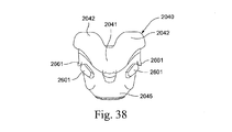
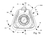
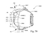
図71〜図87は、本発明の実施形態によるクッション6540を示す。後により詳細に説明するように、クッション6540は、概して鼻梁領域NB、鼻の側面領域SN(鼻の上側および鼻の下側を含む)、鼻の鼻から唇のしわまたは角領域CN、および患者の顔の上唇領域ULに沿って、患者の顔に係合するように適合された鼻インタフェースを提供する(たとえば図74、図78〜図82および図94〜図98参照)。
FIGS. 71-87 show the
クッション6540の顔接触側は、二重壁構造を有し、そこでは、クッションは、アンダークッション6544と少なくとも部分的にアンダークッション6544を覆う膜6546とを有している。図示する実施形態では、鼻梁領域NBにはアンダークッションは設けられておらず、たとえば図79および図95を参照されたい。たとえば図79に示すように、膜6546の自由端はビード6546(I)を有することができる。ビードを含むことにより、膜によって画定されたオリフィスをクッション内に成形することができ、それにより、こうしたオリフィスを形成するために追加の切断が不要である。図示する実施形態では、膜は、比較的薄い厚さ、たとえば約0.2mm〜約0.35mmを含む。
The face contact side of the
クッションは、クッションの1つまたは複数の領域において鎌形を有することができ、たとえば、図79〜図82の上唇領域、鼻の側面領域および鼻の角領域を参照されたい。
使用時、クッションの鎌形は、使用時にクッションの制御された変形を容易にするためにヒンジまたは撓曲部6567(たとえば図98参照)を提供する。また、こうしたクッションの鎌形により、クッションの1つまたは複数の部分がフレーム2020の上に張り出すことができ(たとえば図95〜図98参照)、それによりクッションが使用時に変形するため、フレームがクッションの1つまたは複数の部分を支持することができる。一形態では、この構成によってそれほど剛性でないアンダークッションが提供され、それにより、クッションが使用される変形の範囲にわたり底に達する可能性が低減し、したがってクッションがより快適になる。
The cushion can have a sickle shape in one or more areas of the cushion, see, for example, the upper lip region, the lateral region of the nose and the corner region of the nose in FIGS. 79-82.
In use, the sickle shape of the cushion provides a hinge or flexure 6567 (see, eg, FIG. 98) to facilitate controlled deformation of the cushion during use. Also, the sickle shape of these cushions allows one or more parts of the cushion to overhang the frame 2020 (see, eg, FIGS. 95-98), which causes the cushion to deform during use, thus causing the frame to cushion. Can support one or more parts of. In one embodiment, this configuration provides a less rigid undercushion, which reduces the likelihood that the cushion will reach the bottom over the range of deformations used, thus making the cushion more comfortable.
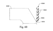
図117は、本発明の実施形態によるアンダークッションまたはバックアップバンド6544の屈曲点または屈曲領域BPを示し、図118、図119および図120は、他の構成のアンダークッション用の屈曲点BPを示す。異なる領域には異なる断面を用いる場合がある。
FIG. 117 shows the bending point or bending region BP of the undercushion or
好ましくは、図117に示す構成は、アンダークッションまたはバックアップバンドの上唇領域に用いられる。この構成を、異なる部分の相対的な厚さに応じて、二重片持ち梁と説明することができる。厚さが増大すると剛性が増大する。断面の形状を、隣接する側壁の横方向にまたは半径方向外側に延在するように配置してもよく、または図118に示すような別のバージョンでは、断面の形状は、隣接する側壁とより一致してもよく、隣接する側壁の内側に折り目または曲りを配置することにより、同様の半径方向外側の広がりを有していてもよい。 Preferably, the configuration shown in FIG. 117 is used for the upper lip area of the undercushion or backup band. This configuration can be described as a double cantilever, depending on the relative thickness of the different parts. As the thickness increases, the rigidity increases. The shape of the cross section may be arranged so as to extend laterally or radially outward of the adjacent side wall, or in another version as shown in FIG. 118, the shape of the cross section may be more than the adjacent side wall. They may match or may have similar radial outer spreads by arranging creases or bends inside adjacent sidewalls.
好ましくは、図119に示す断面は、鼻の側面に沿って用いられるのに適している。この構成により、顔の困難な領域を封止するために加えられる横方向の力を改善することができる。この構成を、異なる部分の相対的な剛性に応じて、三重片持ち梁として説明することができる。 Preferably, the cross section shown in FIG. 119 is suitable for use along the sides of the nose. This configuration can improve the lateral force applied to seal the difficult areas of the face. This configuration can be described as a triple cantilever, depending on the relative stiffness of the different parts.
図120に、単一片持ち梁として説明することができる代替構成を示す。 FIG. 120 shows an alternative configuration that can be described as a single cantilever.
クッション6540の非顔接触側すなわちフレーム側は、その側面に沿って、クッションを適所に固定するようにフレーム2020と係合するかまたは噛み合う細長い突起または係止タブ6550を有し、たとえば図97および図98を参照されたい。クッション6540はまた、その下面に沿って、フレームとインタフェースするかまたは係合する(たとえば図97および図98参照)隆起した固定タブ6552と、クッションの頂点におけるフレームとインタフェースするかまたは係合する隆起した上部タブ6554とを有している。図95は、クッションのフレームへの保持に役立つ、フレーム2020と係合するタブ6554を示す。隆起した上部タブ6554はまた、クッションの型からのロボットによる離型に対して支援を提供することができる。しかしながら、クッションを、他の適切な方法でフレームに接続し、噛み合わせ、かつ/または位置合せしてもよいことが理解されるべきである。
The non-face contact or frame side of the
クッションの非顔接触側は、エルボーを受け入れるかまたは他の方法でエルボーと連通するように適合された開口部6555も有している。図示するように、開口部は、図13−1および図13−2に示すもののようなベント機構を提供することができる。しかしながら、クッションは、たとえば図55〜図59に示すもののような代替的なベント構成を有してもよいということが理解されるべきである。
The non-face contact side of the cushion also has an
鼻梁領域
図79に最もよく示すように、鼻梁領域における膜6546の長さまたは深さd1は、約10mm〜30mm、たとえば15mm〜25mm、たとえば19mm〜20mmの範囲、たとえば19.58mmである。図示するように、深さd1は、膜の開始部周辺(すなわち、薄い封止部が接続部分6547から撓曲/ヒンジ運動することができる場所)から、患者接触部の接線まで延在している。鼻梁領域における膜の深さd1は、本技術分野におけるものより比較的大きく、人体測定学のばらつきに適合するように最適化されている。たとえば、比較的高い鼻梁は、膜内にさらに延在する可能性があり、一方で比較的浅い鼻梁は、膜の撓曲がほとんどかまったくなく膜の上に載る可能性がある。
Nasal bridge region As best shown in FIG. 79, the length or depth d1 of the
上部から見た場合、鼻梁領域における膜6546の形状または曲率はまた、多種多様の患者の顔に適合するように構成されている。(鼻梁領域における扇形(scallop)または湾曲および鼻の側面領域における隆起部分6549を示す)図75に最もよく示すように、鼻梁領域の深さd2は、約10mm〜15mm、たとえば11mm〜12mmの範囲、たとえば11.52mmであり、鼻梁領域における幅d3は、約10mm〜20mm、たとえば15mm〜16mmの範囲、たとえば15.35mmである。
When viewed from above, the shape or curvature of the
深さd2は、最も平坦な鼻に適応するのに十分であり、それにより、膜の縁は鼻梁の上に位置し、隆起部分6549は鼻のそれぞれの側面に位置することになる。より高い鼻梁は、隆起部分においては鼻の側面に係留し、鼻梁領域における膜は、鼻梁が鼻梁領域において膜内に移動しゾーンz内のいずれかで停止することができるように撓曲する。
Depth d2 is sufficient to adapt to the flattest nose, so that the rim of the membrane is located above the bridge of the nose and the raised
幅d3は、広い鼻梁に適応するのに十分である。隆起部分6549は鼻の側面で係留し、それにより、膜は、鼻梁に適応するように屈曲または伸張する。幅d3は、最も広い鼻に適合するように選択され、それにより、隆起部分は、クッションを所望の位置で係留し、安定化しかつ位置決めするように、眼窩の下のより硬質な骨組織の上に常に位置する。
The width d3 is sufficient to accommodate a wide nasal bridge. The raised
使用時、1つの好ましい形態では、膜または封止フラップは鼻梁領域においてアンダークッションによって実質的に支持されていないため、鼻が封止部分内に移動する時、膜は、鼻梁の最高部分において引張状態にある。さらに、それは、好ましくは、鼻梁の最高点に隣接する領域において鼻の側面において「挟み込まれる(pinched in)」。鼻の側面に
おける横方向の力を、鼻梁の高さによって変化するように構成することができる。より深い鼻梁は膜内にさらに押し進み、その領域の張力を増大させ、クッションの側面を引き出して内側に屈曲させるかまたは一端を突出させ、横方向の力を増大させ、鼻の側面における封止を向上させる。鼻梁が比較的低くかつ頬骨が高い顔では、鼻梁に隣接するクッションの領域を外側に広げることができ、膜における張力を増大させ、比較的低い鼻梁に対する封止力を増大させる。本発明の好ましい形態では、バックアップバンドまたはアンダークッションは、鼻梁に隣接する領域における従来技術によるクッションに比較して内側にかつ外側に比較的自由に撓曲する。図116−1〜図116−3を参照されたい。
In use, in one preferred embodiment, the membrane or sealing flap is not substantially supported by the undercushion in the nasal bridge region, so that when the nose moves into the sealing portion, the membrane is tensioned at the highest portion of the nasal bridge. It is in a state. In addition, it is preferably "pinched in" on the sides of the nose in the area adjacent to the highest point of the nasal bridge. The lateral force on the sides of the nose can be configured to vary with the height of the bridge of the nose. The deeper nasal bridge pushes further into the membrane, increasing tension in that area, pulling out the sides of the cushion and bending it inward or protruding one end, increasing lateral force and sealing on the sides of the nose. To improve. For faces with a relatively low nasal bridge and a high cheekbone, the area of the cushion adjacent to the nasal bridge can be extended outward, increasing tension in the membrane and increasing sealing force for the relatively low nasal bridge. In a preferred embodiment of the invention, the backup band or undercushion flexes relatively freely inwardly and outwardly as compared to prior art cushions in the area adjacent to the bridge of the nose. See FIGS. 116-1 to 116-3.
鼻の側面
鼻の側面におけるアンダークッション6544を、特に鼻が頬に遷移する際の顔の湾曲により、クッションを係留し、膜を位置決めし安定化するように構成した。この湾曲は、患者によって異なる可能性がある。アンダークッションは、膜を位置決めし、膜がしわにならないように膜の外形を維持する。
Side of the nose The
アンダークッション6544に、鼻の角領域または上唇領域等のアンダークッションの他の領域より広いフラップまたは伸張部分6545がある。この構成により、膜がアンダークッションによって支持される領域において、非常に薄い鼻が膜に接触することができることが確実になり、鼻から頬への膜の平滑な遷移が確実になる。より広い鼻は膜のより広い領域に接触し、アンダークッションのより広い部分が膜を支持する。
The
図74は、アンダークッションのフラップ6545のおよその位置の指示を提供するためにさまざまな例示的な寸法を示す。一実施形態では、d4は、約5mm〜15mm、たとえば9mm〜10mm、たとえば9.26mmであり、d5は、約10mm〜15mm、たとえば12mm〜13mm、たとえば12.80mmであり、d6は、約20mm〜25mm、たとえば22mm〜23mm、たとえば22.10mmであり、d7(たとえば、フラップの底部から上唇領域までの距離)は、約10mm〜20mm、たとえば15mm〜16mm、たとえば15.58mmである。図75は、フラップの頂部6546から上唇領域におけるクッションのおよその接触点までの例示的な距離d8も示している。
クッションは、通常、患者の上唇のおよそ同じ場所に位置するが、クッションが鼻梁の上で位置する可能性のある場所は変化する可能性がある。したがって、フラップは、鼻の側面に位置するために、上唇領域から十分な距離に間隔を空けて配置される。
FIG. 74 shows various exemplary dimensions to provide an indication of the approximate position of the
The cushion is usually located approximately the same on the patient's upper lip, but the location where the cushion may be located on the bridge of the nose can vary. Therefore, the flaps are spaced sufficiently apart from the upper lip area to be located on the sides of the nose.
図83は、アンダークッション6544のフラップ6545の最も幅の広い部分の断面図である。図示するように、フラップは比較的大きい半径を有し、それにより、過度の圧力が鼻の側面に加わらないように(たとえば、こうした圧力は、外鼻孔を閉塞させるかまたは締め付ける感覚をもたらす可能性がある)、アンダークッションは容易に内側に丸まるかまたは撓曲することができる。一実施形態では、外面の半径r1は約12mm〜20mm、たとえば16mmであり、内面の半径r2は約8mm〜16mm、たとえば12mmである。また、フラップの自由端に向かう厚さt1は、容易な撓曲を可能にするために約0.5mm〜1.5mm、たとえば0.9mmであり、フラップの自由端から内側への厚さt2は、アンダークッションを崩壊せずにヒンジ運動を促進するように約1.0mm〜1.5mm、たとえば1.2mmである。
FIG. 83 is a cross-sectional view of the widest portion of the
フラップ6545の長さは、頂部からフラップのフレームへの接続部またはクッションの正面まで測定される。フラップの長さは約10mm〜30mmである。好ましくは、フラップの長さは約15mm〜25mmである。最も好ましくは、フラップの長さは約18mm〜23mmである。最も好ましくは、フラップの長さは約20mmである。
The length of the
鼻のしわまたは角
鼻のしわまたは角におけるアンダークッションを、この領域においてマスクを安定化するかまたは係留するように構成した。また、顔のこの領域の形状が複雑である可能性があり、すなわち、鼻孔の広がり、上唇および頬領域は皮膚の窪みおよび/またはしわにおいて一体となるため、鼻のしわまたは角は、本質的に封止するのが困難である。この領域では、アンダークッションは、膜を十分に支持するようにより剛性であり、それにより、膜を、このより複雑な形状に当接するかまたは適合するように配置することができる。(クッションの半分に対するアンダークッションを示す)図84に示すように、鼻の角領域のアンダークッションは、その剛性を増大させるために局所的な厚化を含む。一実施形態では、局所的な厚さt3は、約1mm〜2mm厚さ、たとえば1.4mm厚さであり得る。
また、図81および図82は、鼻の角領域CNにおけるアンダークッションと、その比較的厚い厚さおよびより狭い半径とを示す。
Nose wrinkles or horns Undercushions in nasal wrinkles or horns were configured to stabilize or moor the mask in this area. Also, the shape of this area of the face can be complex, i.e. the widening of the nostrils, the upper lip and cheek areas are united in the skin depressions and / or wrinkles, so the wrinkles or horns of the nose are essential. Difficult to seal in. In this area, the undercushion is more rigid to support the membrane sufficiently so that the membrane can be placed to abut or fit into this more complex shape. As shown in FIG. 84 (showing the undercushion for half of the cushion), the undercushion in the corner of the nose contains a local thickening to increase its stiffness. In one embodiment, the local thickness t3 can be about 1 mm to 2 mm thick, for example 1.4 mm thick.
Also, FIGS. 81 and 82 show the undercushion in the nasal weapon region CN, its relatively thick thickness and narrower radius.
図85は、アンダークッション6544の鼻の角領域の断面図を示す。一実施形態では、外面の半径r3は約5mm〜15mm、たとえば8mmであり、内面の半径r4は約2mm〜8mm、たとえば4.85mmである。また、アンダークッションの先端の厚さt4は、約0.5mm〜1.5mm、たとえば0.85mmであり、アンダークッションのピークの厚さt5は約1mm〜2mm、たとえば1.4mmである。ピークの厚さt5は、膜を安定化し、アンダークッションの基部bではなくこの箇所を中心とするヒンジ運動をもたらすように比較的厚い。
FIG. 85 shows a cross-sectional view of the nose corner region of the
上唇領域
図79および図95に最もよく示すように、上唇領域ULにおけるアンダークッションを、敏感な歯肉組織に適応するように構成した。したがって、この領域におけるアンダークッションの厚さは約0.5mm〜1.0mm、たとえば0.7mmである。上唇領域におけるアンダークッションの厚さは、アンダークッションの他の領域に比較して最も薄くてもよい。上唇領域におけるアンダークッションの半径は、クッションが上唇領域に係留しているのではなく載っていることを意図して比較的大きい。一実施形態では、上唇領域の半径は一定でなくてもよく、たとえば、その中心の半径r5は約65mm〜75mm、たとえば72.71mmであり、鼻の角領域に向かう半径r6は約30mm〜40mm、たとえば36.85mmである。
Upper lip region As best shown in FIGS. 79 and 95, the undercushion in the upper lip region UL was configured to adapt to sensitive gingival tissue. Therefore, the thickness of the undercushion in this region is about 0.5 mm to 1.0 mm, for example 0.7 mm. The thickness of the undercushion in the upper lip area may be the thinnest compared to other areas of the undercushion. The radius of the undercushion in the upper lip area is relatively large with the intention that the cushion rests rather than mooring in the upper lip area. In one embodiment, the radius of the upper lip region does not have to be constant, for example, the radius r5 of the center thereof is about 65 mm to 75 mm, for example 72.71 mm, and the radius r6 toward the corner region of the nose is about 30 mm to 40 mm. For example, 36.85 mm.
本技術によるマスクは、着用者の顔および鼻のサイズおよび形状に応じて封止力を適応させることができる。たとえば、上唇領域では、封止力は、アンダークッションまたはバックアップバンドを介する圧縮力と膜または顔フラップの張力との両方の結果であり得る。広い鼻は、クッションの角を外側に広げ、封止を行うために顔に加えられる張力の大きさを増大させることができる。こうした構成は、この領域における顔のより平坦な形状に対して適している可能性がある。 The mask according to the present technology can adapt the sealing force according to the size and shape of the wearer's face and nose. For example, in the upper lip region, the sealing force can be the result of both compressive force through the undercushion or backup band and tension of the membrane or facial flap. The wide nose can widen the corners of the cushion outwards and increase the amount of tension applied to the face to perform the seal. Such a configuration may be suitable for the flatter shape of the face in this area.
膜とアンダークッションとの関係
図示する実施形態では、膜は、クッションの種々の領域におけるアンダークッションからの距離が変化する可能性があり、すなわち、膜とアンダークッションとの間の間隙が、クッションの種々の領域で異なる可能性がある。より多くの多様性がある顔の形態の領域(たとえば鼻の頂部および側面等)では、膜が撓曲するための追加の領域を可能にするためにより広い間隙を提供することができる。また、膜が伸張するかまたは上唇に引張力を上唇に加える傾向がある、上唇領域等の領域では、より低い可撓性、したがって膜のより高い支持力を可能にするように、より小さい間隙を提供することができる。図76および図79は、クッションの種々の領域におけるアンダークッションと膜との間の間隙の例示的な距離を示す。一実施形態では、距離d9は約5.8mm〜6.0mm、たとえば5.89mmであり、d10は約4.8mm〜5.0mm、たとえば4.93mmであり、d11は約4.2mm〜4.4mm、たとえば4.29mmであり、d12は約4.0mm〜4.2mm、たとえば4.06mmであり、d13は約3.2mm〜3.4mm、たとえば3.3mmであり、d14は約3.4mm〜3.6mm、たとえば3.49mmであり、d15は約3.7mm〜3.9mm、たとえば3.76mmであり、d16は約3.7mm〜3.9mm、たとえば3.76mmである。
Relationship between Membrane and Undercushion In the illustrated embodiment, the membrane can vary in distance from the undercushion in different areas of the cushion, i.e., the gap between the membrane and the undercushion is the cushion. It can be different in different areas. Areas of facial morphology with more diversity (eg, top and sides of the nose, etc.) can provide wider gaps to allow additional areas for the membrane to flexure. Also, in areas such as the upper lip area where the membrane tends to stretch or apply tensile force to the upper lip, smaller gaps allow for lower flexibility and thus higher bearing capacity of the membrane. Can be provided. 76 and 79 show exemplary distances of the gap between the undercushion and the membrane in various areas of the cushion. In one embodiment, the distance d9 is about 5.8 mm to 6.0 mm, for example 5.89 mm, d10 is about 4.8 mm to 5.0 mm, for example 4.93 mm, and d11 is about 4.2 mm to 4. It is .4 mm, for example 4.29 mm, d12 is about 4.0 mm to 4.2 mm, for example 4.06 mm, d13 is about 3.2 mm to 3.4 mm, for example 3.3 mm, and d14 is about 3. It is 3.4 mm to 3.6 mm, for example 3.49 mm, d15 is about 3.7 mm to 3.9 mm, for example 3.76 mm, and d16 is about 3.7 mm to 3.9 mm, for example 3.76 mm.
封止力
図86および図87は、使用時に患者の鼻の側面および正面から見たクッションの例示的な封止力を示す概略図である。
Sealing Forces FIGS. 86 and 87 are schematic views showing exemplary sealing forces of a cushion as viewed from the side and front of the patient's nose during use.
図86に示すように、鼻梁領域におけるクッションは、Aに示す鼻の鼻根(sellion)または窪みに沿って封止しない。むしろ、鼻梁領域におけるクッションは、Bで示す鼻梁の下部領域に沿って封止する。クッションが鼻の下方を封止するため、鼻梁領域におけるアンダークッションの比較的大きい切取部が提供される(たとえば、図74の切取部6557参照)。すなわち、鼻は、鼻の下方に向かって広くなるため、切取部は広範囲の患者に適応するために十分広い。
As shown in FIG. 86, the cushion in the nasal bridge region does not seal along the sellion or depression of the nose shown in A. Rather, the cushion in the nasal bridge region seals along the lower region of the nasal bridge indicated by B. Since the cushion seals the lower part of the nose, a relatively large cutout of the undercushion in the nasal bridge region is provided (see, for example,
鼻梁領域における膜は、患者の鼻梁に力を加えるために伸張効果を含み、すなわち、膜の伸張または弾性を用いて、クッションの他の領域におけるようにアンダークッションではなく鼻梁に力が加えられる。たとえば、クッションは、膜とアンダークッションとの間に間隔または間隙が提供されなくなるまで、患者の顔に押し付けられる。鼻梁領域にアンダークッションが設けられていないため、膜は、クッションが患者の顔に押し付けられるに従って伸張し、すなわち図75に示す隆起部分6549を横切って伸張する。伸張するかまたは拡張する膜は、鼻梁に力を加えるピンと張ったトランポリン状の膜部分を提供する。
The membrane in the nasal bridge region contains a stretching effect to exert force on the patient's nasal bridge, i.e., the stretching or elasticity of the membrane is used to force the nasal bridge rather than the undercushion as in other areas of the cushion. For example, the cushion is pressed against the patient's face until no space or gap is provided between the membrane and the undercushion. Since there is no undercushion in the nasal bridge region, the membrane stretches as the cushion is pressed against the patient's face, i.e., stretches across the raised
たとえば、図116−1、図116−2および図116−3は、伸張および引張による鼻梁領域NBにおける封止を示す。図116−1は、患者の鼻に接触する前のクッションを示す。図示するように、膜または顔フラップ6546は、アンダークッションまたはバックアップバンド6544から間隔が空けられている。図116−2は、膜がアンダークッションに係合するように鼻が膜6546に接触している状態を示し、それにより、膜が鼻梁領域におけるアンダークッションによって画定される間隙にわたって引張状態になる(この図では点荷重として示す)。鼻が、図116−3に示すようにクッション内にさらに押し込まれると、アンダークッションは、片持ち梁ばねとして作用し、屈曲し始める(この図では点荷重として示す)。
For example, FIGS. 116-1, 116-2 and 116-3 show sealing in the nasal bridge region NB by stretching and tensioning. FIG. 116-1 shows the cushion before contacting the patient's nose. As shown, the membrane or
膜の表面を、摩擦をもたらし封止を向上させるために艶消しするかまたは研磨してもよい。器具の表面を研磨することにより、より粘着性の感覚をもたらし、摩擦を増大させることができる。艶消しされた封止面を、器具の表面の粗さを増大させることによって提供することができる。艶消し面は、領域によっては好ましい場合がある。 The surface of the membrane may be matted or polished to provide friction and improve sealing. Polishing the surface of the instrument can provide a more sticky sensation and increase friction. A matte sealing surface can be provided by increasing the roughness of the surface of the instrument. The matte surface may be preferable depending on the region.
図87および図87−2に示すように、アンダークッションの湾曲したフラップ6545は、鼻の側面内にかつ鼻のCで示す通気孔の上方に封止力を提供するように構成されている。湾曲したフラップは、鼻の側面を押しかつ/または側面で丸くなるとともに、鼻を包囲する(鼻梁領域を除く)。フラップの上方の頂点までにはアンダークッションはない。フラップ間の間隙Gは、最小の鼻の人に適合するように寸法が決められており、すなわち、間隙は、フラップが広範囲の患者の鼻の側面に確実に接触するように十分狭い。一実施形態では、間隙Gは約10mm〜30mm、たとえば15mm〜25mm、たとえば18.5mmである。
As shown in FIGS. 87 and 87-2, the
フラップ6545の好ましい比較的大きい半径の結果として、各フラップは、側壁の剛性部分から十分に間隔が空けられている低い鼻梁タイプの鼻に対する屈曲点を画定する。
使用時、各フラップは、低い鼻梁が側壁の剛性部分に接触することなく屈曲しまたは丸くなる。図87−1(a)は、低い鼻梁に対するフラップの例示的な変形を示し、図87−1(b)は、高い鼻梁に対するフラップの例示的な変形を示す。この構成は、広い/低い鼻が側壁の剛性の領域に接触することができるようにするより小さい半径を有する、本技術分野において既知であるアンダークッションとは対照的である。
As a result of the preferred relatively large radius of the
In use, each flap bends or rounds without the low nasal bridge touching the rigid portion of the sidewall. FIG. 87-1 (a) shows an exemplary deformation of the flap for a low nasal bridge, and FIG. 87-1 (b) shows an exemplary deformation of the flap for a high nasal bridge. This configuration is in contrast to the undercushion known in the art, which has a smaller radius that allows the wide / low nose to contact the area of rigidity of the sidewall.
図87に示すように、鼻の角領域の厚化されたアンダークッションは、Dで示す鼻のしわにおいて患者の顔の平面内に封止力を提供する。顔のこの領域はそれほど敏感でなく、患者の顔にマスクを安定化するためのより大きい力に耐えることができる。鼻のしわにおける封止は、この領域を通過するフルフェースクッションとは対照的に、鼻クッションには重要である。したがって、アンダークッションは、鼻の角またはしわ領域では比較的剛性であって、しわにおいて食い込み、患者の顔の平面内にクッションを押し込むことにより、封止し安定化する。また、しわ領域におけるクッションは、使用時に制御された変形を提供するように鎌形を含む(たとえば図82参照)。 As shown in FIG. 87, the thickened undercushion in the nasal corner region provides a sealing force in the plane of the patient's face in the nasal wrinkles indicated by D. This area of the face is less sensitive and can withstand greater forces to stabilize the mask on the patient's face. Encapsulation in nasal wrinkles is important for nasal cushions, as opposed to full face cushions that pass through this area. Therefore, the undercushion is relatively rigid in the corners of the nose or in the wrinkled area and is sealed and stabilized by biting into the wrinkles and pushing the cushion into the plane of the patient's face. The cushion in the wrinkled area also includes a sickle shape to provide controlled deformation during use (see, eg, FIG. 82).
患者の上唇(図86においてEで示す)において封止力を提供する、唇領域のアンダークッションは、快適さのために(たとえばしわ領域に比較して)比較的剛性ではない。 The undercushion of the lip region, which provides a sealing force on the patient's upper lip (indicated by E in FIG. 86), is relatively non-rigid (eg, compared to the wrinkled region) for comfort.
アンダークッションの形状、サイズ、丸まりおよび/または厚さを、顔の種々の領域における力を変化させるように変更することができる。 The shape, size, roundness and / or thickness of the undercushion can be changed to vary forces in different areas of the face.
3.4代替的な封止機構
図5−1〜図5−6は、封止機構440の代替実施形態を示す。封止機構440は、上述したものと同様にフレーム420の本体422の開口部に受け入れられるように構成されている1つまたは複数の突起450を有することができる。封止機構440はまた、上述したようなクッションを含むことができる。たとえば、封止機構440は、アンダークッションおよび膜、または上述したようなフォームクッションおよびシリコーンクッションを含むことができる。
3.4 Alternative Sealing Mechanisms FIGS. 5-1 to 5-6 show alternative embodiments of the
クッションは、鼻梁においてアンダークッションが切り取られたかまたは除去されている、二重壁封止を有することができる。上頬または鼻の側面におけるアンダークッションを、使用者の顔の上でクッションを安定化するように隆起させてもよい。クッションは、研磨された外面および艶消しされた内面を有していてもよい。クッションを、シリコーンまたは他の任意の適切な材料から作製することができる。 The cushion can have a double wall seal in which the undercushion has been cut or removed at the bridge of the nose. The undercushion on the side of the upper cheek or nose may be raised on the user's face to stabilize the cushion. The cushion may have a polished outer surface and a matte inner surface. The cushion can be made of silicone or any other suitable material.
3.5代替的なクッション
図11−1において、クッション540の両側面は突起550を有し、突起550は、上述したようにフレームと噛み合うように適合された保持機能を提供する。フレームの上端は、ブランド表示(branding)およびクッション保持のためのランド部(landing)541を有し、フレームの各側面は、保持に役立ちかつフレームの上端部でのランド部と審美的に調和するようにカップ状部分543を有している。
3.5 Alternative Cushion In FIG. 11-1, both sides of the
図11−2〜図11−9は、別の実施形態によるクッション540−1のさまざまな図を示す。図11−8および図11−9に最もよく示すように、クッションの顔接触部(たとえば膜546、アンダークッション544および側壁542)は、快適さおよび可撓性を向上させるように、鎌形または疑問符形状を提供する。
11-2 to 11-9 show various views of the cushion 540-1 according to another embodiment. As best shown in FIGS. 11-8 and 11-9, the facial contact of the cushion (eg,
図11−6〜図11−9に最もよく示すように、クッション540−1は、クッションの正面、すなわちシールとエルボーとの間の部分に、衝撃吸収部545を有している。衝撃吸収部は、薄化領域であり、2mm〜3mm厚さのクッションの他の部品に比較してたとえば1mm厚さである。
As best shown in FIGS. 11-6 to 11-9, the cushion 540-1 has a
図15−1〜図15−3は、フレームと係合するクッション540−1のさまざまな図である。上述した構成に類似して、クッションは、フレーム520の側壁に沿ってそれぞれの開口部と係合するかまたは噛み合うように適合された突起550を有している。
15-1 to 15-3 are various views of the cushion 540-1 that engages the frame. Similar to the configuration described above, the cushion has
一実施形態では、クッションが使用されている時の患者の上唇に対する圧力による不快を防止するように、上唇領域におけるアンダークッションを除去することができる。 In one embodiment, the undercushion in the upper lip region can be removed to prevent pressure discomfort on the patient's upper lip when the cushion is being used.
一実施形態では、クッションの患者側は艶消し仕上げを含むことができ、クッションの非患者側は研磨仕上げを含むことができる。 In one embodiment, the patient side of the cushion can include a matte finish and the non-patient side of the cushion can include a polished finish.
3.6さらなる代替的なクッション
クッション2010の実施形態を図33〜図39に示す。クッション2010を、さまざまな患者に単一サイズで適合するように設計することができる。これを達成するため、クッション2010のさまざまな領域を、大きい鼻および小さい鼻に快適に適合するように撓曲しかつ適応するように調整することができる。
3.6 Further Alternative Cushions Embodiments of the
膜2040は、使用時に患者の顔と接触しそれと封止する。鼻梁領域2041は、使用時に患者の鼻の鼻梁または上部と当接するように構成されている。鼻梁領域2041は、使用時に患者の鼻の上に伸張することができるように弾性変形可能であり得る。隆起した側面部分2042が、使用時に患者の目に近接する患者の鼻の側面と係合しそれを圧迫することができる。この圧迫力により、患者の鼻の側面においてクッションの係合が安定化することができる。圧迫力はまた、広い鼻に対して、鼻梁領域2041が患者の鼻梁の上で伸張することも意味することができる。代替的に、鼻梁領域2041は、伸張せずに患者の鼻の上にあるかまたは当接してもよい。さらに、鼻梁が高い患者が、自身の鼻を膜の上に配置し、使用時に自身の長い鼻梁にわたって膜の鼻梁領域2041を撓曲させることができるように、鼻梁領域2041はより深いかまたは長い。
使用時にクッションがより平坦かまたは浅い鼻と封止することができるように、側部フラップ2043が、より長いかまたはマスククッション内により深く延在する。患者が高い鼻梁を有する場合に側部フラップ2043がクッション内に撓曲することができるように、側部フラップ2043は可撓性であってもよい。
The
膜の上のピーク2046は、隆起部分、または膜の他の領域に比較した場合により高い部分であり得る。これは、使用時に鼻孔または外鼻孔の広がりに対して近位の使用者の鼻の角にクッションを固定するためであり得る。
The
上唇領域2044は、膜の下部に配置され、使用時に使用者の上唇と係合するかまたはその上に載ることができる。湾曲は、患者のさまざまな上唇形状に一致するように延びていてもよい。
The
可撓性部分2045を、エルボーまたはスイベルリングのクッション2040上の接続に対して近位に配置することができる。可撓性部分2045は、クッションからの管の分離を可能にする、薄化材料またはより可撓性の材料の領域であってもよい。
The
係止タブ2601を、クッションの正面領域の少なくとも1つの部分に配置することができる。係止タブ2601は、フレームと組み立てられた時にクッションを適所に固定する隆起した外形またはピークを有することができる。
The
固定タブ2661もまた、クッションの正面領域の少なくとも1つの部分に配置することができる。固定タブ2661もまた、フレームとインタフェースするかまたは他の方法で係合するために、クッションの他の部分より高い可能性がある。
The
上部タブ2651は、クッションの頂点に配置された隆起部であり得る。上部タブ2651を、クッションのより容易なロボット離型を可能にするとともに、フレームと係合するように配置することができる。
The
クッションのオリフィスに、エルボーまたは呼吸に適した供給気体を受け入れるように、ベントリングまたはスイベルリング2090を配置することができる。ベントリング2090を、クッション2010と成形するかまたは他の方法でクッション2010に永久的に取り付けることができる。ベントリング2090は、マスクシステムからの気体の排出を可能にするように、周縁部の少なくとも一部に通気孔を有することができる。
A vent ring or
図40〜図45は、本発明の実施形態による、互いに組み立てられた上述したクッション2100およびフレーム2020を示す。
40-45 show the
4.エルボー
エルボー70は、第1の端部72および第2の端部74を有し、たとえば図1−2、図2−2および図2−5を参照されたい。第1の端部72は、封止機構40にインタフェースするかまたは他の方法で取り付けられるように構成されたインタフェース構造を提供する。第2の端部74は、空気送達管に接続されるように適合されている。第1の端部は第2の端部に対して約135°に角度付けられている。しかしながら、エルボーの第1の端部および第2の端部は、互いに対して他の適切な角度、たとえば0°、90°、120°等を有していてもよい。
4. Elbow The
一実施形態では、エルボーは、開示内容がすべて参照により本明細書に組み込まれている、2008年10月22日に出願された特許文献3に開示されているものと同様であり得る。
In one embodiment, the elbow may be similar to that disclosed in
4.1封止機構へのエルボーの接続
封止機構40は、エルボー70を、患者の顔に対して動作位置で維持するように構成されている。すなわち、封止機構は、エルボー70に対する支持体および支持面として作用することができる。封止機構およびエルボーは、摩擦嵌合、スナップ嵌合、機械的な噛合いまたは他の適切な取付機構で接続することができる。しかしながら、エルボーを封止機構に取り付ける他の適切な構成が可能である。
4.1 Connecting the Elbow to the Sealing Mechanism The
図示する例では、エルボー70を封止機構40に結合するためにスイベルリング90が設けられている。こうしたスイベルリング90は任意の部品であり、スイベルリングなしにエルボー70を封止機構40に直接結合してもよいことが理解されるべきである。
In the illustrated example, a
図2−5に最もよく示すように、スイベルリング90は、その外周に沿って、シリコーンクッション242の開口部255(または図1−1〜図1−4のクッション42の開口部55)を画定する環状フランジ256と噛み合うように適合された環状溝92を有している。スイベルリング90の内周は、エルボー70の第1の端部72の外面と係合するように適合された比較的平滑な環状面94を提供する。第1の端部72の自由端は、スイベルリング90の内側肩部と、たとえばスナップ嵌合で係合する環状ビード73を提供する。こうした接続により、エルボーが適所に保持され(たとえば、好ましくは比較的気密接続)、封止機構に対してエルボーの回転または旋回が可能になる。
As best shown in FIG. 2-5, the
スイベルリングは、封止機構(たとえば、プラスチック、シリコーン、フォームからなる)より剛性の材料から構成される。この構成により、エルボー、たとえば硬質のエルボーの軟質な封止機構への接続ではなく、硬質のエルボーの硬質のスイベルリングへの接続を容易にすることができる。一例では、たとえば部品を低減するために、スイベルリングを、封止膜またはクッションと共成形し、機械的にオーバモールドし、かつ/または化学結合によりオーバモールドしてもよい。代替的に、スイベルリングを、たとえば分解を可能にするように、別個の部品として提供してもよい。 The swivel ring is made of a material that is more rigid than the sealing mechanism (eg, consisting of plastic, silicone, foam). This configuration facilitates the connection of a hard elbow to a hard swivel ring rather than to a soft sealing mechanism of an elbow, eg, a hard elbow. In one example, the swivel ring may be co-molded with a sealing membrane or cushion, mechanically overmolded, and / or overmolded by chemical bonding, for example to reduce components. Alternatively, the swivel ring may be provided as a separate component, eg, to allow disassembly.
また、開口部55、255を包囲するクッションの領域は、たとえば管の抗力を低減するために、エルボーのマスクシステムの残りの部分からの分離を可能にするように幾分か可撓性を有することができる。たとえば、クッション開口部55とエルボー70との間の分離機構は、開口部55の領域におけるクッション42上の可撓性ジンブル(gimble)または膜を含むことができる。同様の分離機構は、開示内容がすべて参照により本明細書に組み込まれている、2009年3月4日に出願された特許文献4に記載されている。ジンブル領域の厚さは、ジンブル領域に隣接するクッションの厚さの1/3であってもよい。
好ましくは、ジンブルの厚さは、ジンブル領域に隣接するクッションの厚さの1/3未満であってもよい。最も好ましくは、ジンブル領域の厚さは、ジンブル領域に隣接するクッションの厚さの1/2未満である。図79、図96および図98は、封止部とエルボー開口部との間のクッション6540の正面における別の例示的なジンブル領域6565を示す。図示するように、ジンブル領域は、厚くなる領域および薄くなる領域を含み、薄くなる領域はエルボー開口部に向かっている。
Also, the area of the cushion surrounding the
Preferably, the thickness of the gimble may be less than 1/3 of the thickness of the cushion adjacent to the gimble region. Most preferably, the thickness of the gimble region is less than half the thickness of the cushion adjacent to the gimble region. 79, 96 and 98 show another
クッションとエルボーとの間の封止機構を、開示内容がすべて参照により本明細書に組み込まれている特許文献5に記載されているものと同様であり得る。 The sealing mechanism between the cushion and the elbow may be similar to that described in Patent Document 5, the entire disclosure of which is incorporated herein by reference.
図4−1〜図4−4は、エルボー70をクッション42に結合する代替構成を示す。図4−1では、クッション42は、開口部55から内側に、使用時にエルボー70の端部に対して封止するように適合された締まりリップシール57を有している。図4−2は、図4−1のリップシール57に対する代替的な封止機構を示す。図示するように、リップシール57(1)は、たとえば図4−1の構成のように、エルボー70の端部に対して封止することができる。代替的に、リップシール57(2)を、エルボー70の周縁を封止するように構成することができる。図4−3は、上述したようなスイベルリング90を介してクッション42に取り付けられたエルボー70を示す。この実施形態では、クッションは、使用時にエルボー70の端部に対して封止するように適合された、内側に延在する締まりリップシール57を提供する。図4−4は、スイベルリング90が、使用時にエルボー70を保持しかつ/またはエルボー70の周縁を封止するように適合された、内側に延在するリップシール91を提供する構成を示す。
FIGS. 4-1 to 4-4 show an alternative configuration in which the
一例では、エルボーの第2の端部にスイベルを設け、空気送達管に接続されるように適合させることができる。図4−5は、スイベル95の一例を示す。図4−6〜図4−9は、エルボー70とスイベル95との間に封止を形成する代替構成を示す。図4−6に示すように、エルボーと封止するためにスイベル95の内面にリップシール96を設ける(たとえばオーバモールドする)ことができる。図4−7に示すように、スイベル95は、エルボー70のそれぞれの端部から張り出すように適合されたフランジ部97(1)、97(2)を有することができる。この実施形態では、エルボー70は、スイベル85の端部を受け入れかつ保持する溝71を画定する。図4−8では、スイベル95の端部は、エルボー70のフランジ73にクリップ留めするように適合された弾性クリップ部98を有している。また、エルボー70と封止するために、スイベル95の内面にリップシール96を設けることができる。リップシール96を、使用時にエルボー70と係合するように付勢されるように構成することができる。図4−9はスイベル95を示し、そこでは、内部リップシール96がスイベル95とは別個に形成され、たとえばスピン溶接または接着剤によりスイベル95に取り付けられている。
In one example, a swivel can be provided at the second end of the elbow and adapted to be connected to an air delivery tube. FIG. 4-5 shows an example of the
ベント機構
図1−1および図1−2に示すように、エルボー70は、ガス洗い出しのためのベント機構75を有している。ベント機構75は、複数の孔(たとえば、5〜100の孔、たとえば20〜50の孔、または約45の孔)を有している。図2−5に示すように、各孔は、その長さに沿ってなだらかな起伏またはテーパを有していてもよい。しかしながら、ベント機構は、他の適切な構成、たとえば、異なる数の孔、孔構成、1つまたは複数の通気孔を有するベントインサート等を含んでもよいことが理解されるべきである。
Vent Mechanism As shown in FIGS. 1-1 and 1-2, the
ベントは、開示内容がすべて参照により本明細書に組み込まれている。特許文献6に開示されているような拡散ベント(diffuse vent)であってもよい。
Vent is incorporated herein by reference in its entirety. It may be a diffuse vent as disclosed in
4.3代替的なエルボー
図12−1〜図12−3は、非通気式エルボーの実施形態のさまざまな図を示し、図12−4〜図12−8は、非通気式エルボーの別の実施形態のさまざまな図を示す。各エルボー570は、クッションに接続するように適合されたクッション接続端570(1)と、空気送達管に接続するように適合された管接続端570(2)とを有している。図12−4〜図12−8では、エルボーの側面は、使用者がエルボーを掴持し迅速にクッションから解放するために「ボタン」箇所または可撓性指部573を提供する。
4.3 Alternative elbows FIGS. 12-1 to 12-3 show various diagrams of embodiments of the non-ventilated elbow, FIGS. 12-4 to 12-8 are another of the non-ventilated elbows. Various diagrams of embodiments are shown. Each
図12−4〜図12−8に最もよく示すように、エルボーは、より剛性の領域(ポリプロピレンまたはポリカーボネート等のポリマーから構成される)と共成形することができる可撓性領域571(軟質かつ感触のよい(tactile)TPEまたは可撓性ポリマーからなる)を含む。可撓性領域は、エルボーの部分が、患者がこれらの領域をつまむかまたは圧搾する時に内側に撓曲することができるようにし、クッション接続端のマスクからの分離を可能にする。 As best shown in FIGS. 12-4 to 12-8, the elbow is a flexible region 571 (soft and flexible) that can be co-molded with a more rigid region (composed of a polymer such as polypropylene or polycarbonate). Includes (consisting of tactile TPE or flexible polymer). The flexible regions allow the elbow portions to flex inward as the patient pinches or squeezes these regions, allowing separation of the cushion connection end from the mask.
この構成により、エルボーの封止、価値を高める柔らかい感触の特徴、部品をより魅力的にするための部品に対する何らかの色および容易な組立ても可能になる。 This configuration allows for elbow encapsulation, a soft feel feature that enhances value, some color for the part and easy assembly to make the part more attractive.
図12−9に示すように、使用時に可撓性領域が空気路を閉塞しないように、エルボー内に止め具575(1)があってもよい。エルボーの環状体に強度を提供するため、かつ止め具を適所に維持するために、エルボーの内側に支持ビーム575(2)を設けてもよい。 As shown in FIG. 12-9, there may be a stopper 575 (1) in the elbow so that the flexible region does not block the air passage during use. A support beam 575 (2) may be provided inside the elbow to provide strength to the elbow ring and to keep the stopper in place.
一実施形態では、TPE部分をエルボーのクッション接続端の上に成形して、クッションに接続された時のエルボーのより優れた封止および回転の容易性を可能にすることができる。 In one embodiment, the TPE portion can be molded over the cushion connection end of the elbow to allow for better sealing and rotation of the elbow when connected to the cushion.
後述するようにベントリングを使用することにより、エルボーを非通気式とすることができる。 The elbow can be made non-ventilated by using a vent ring as described below.
一実施形態では、エルボーは艶消し仕上げを含むことができる。 In one embodiment, the elbow can include a matte finish.
4.4スイベル/ベントリング
スイベル/ベントリングは、クッションとエルボーとの間のインタフェースを提供する、すなわちエルボーがクッションに接続するのを可能にするために提供される。図13−1に示すように、リング590は、クッション接続のためのインタフェース591と、エルボー接続のためのインタフェース593と、拡散通気を提供するリングの周縁に沿った通気孔595とを提供する。一実施形態では、リングをクッションと共成形する(化学的保持または機械的保持のいずれかにより)ことができる。
4.4 Swivel / Vent Ring A swivel / vent ring is provided to provide an interface between the cushion and the elbow, i.e. to allow the elbow to connect to the cushion. As shown in FIG. 13-1, the
リングは、流れの調整の容易性(すなわち、通気孔を追加するかまたは除去することができる)、CO2洗い出しの改善、加湿要件の制御、拡散性の向上、邪魔にならないこと、エルボーに通気孔がないことによるエルボー製造の容易性を提供し、かつ/またはエルボーの審美的自由を容易にする。 Rings allow for ease of flow adjustment (ie, vents can be added or removed), improved CO2 washout, control of humidification requirements, improved diffusivity, unobtrusive, vents on elbows Provides ease of elbow production due to the absence and / or facilitates the aesthetic freedom of the elbow.
一実施形態では、リップシールにリングを設ける(たとえば共成形する)ことができる。たとえば、図13−2に示すように、リングを、患者側の通気孔595の間の溝596とともに成形することができ、それにより、クッションを作成する器具にベントリングを配置することができ、クッションを作成するための材料が器具内に充填されると、クッション材料の一部が、通気孔の間の溝を通って流れ、リップシール597を形成する。リップシール597は、クッション540とエルボー570との間により有効な封止を提供することができる。ベントリングにリップシールを成形することは、患者が操作する部品を低減するのに有利である。
In one embodiment, the lip seal can be provided with a ring (eg, co-molded). For example, as shown in FIG. 13-2, the ring can be formed with a
一実施形態では、リングは、非通気式マスク実施形態または通気式エルボーで使用されるように非通気性(すなわち、通気孔なし)であってもよい。 In one embodiment, the ring may be non-breathable (ie, without vents) as used in non-breathable mask embodiments or ventilated elbows.
4.5代替的なエルボーおよびスイベル
図46〜図50は、エルボー3000およびスイベル3500の実施形態を示す。
4.5 Alternative Elbows and Swivels FIGS. 46-50 show embodiments of
エルボー3000は、マスク(たとえば、上述したクッション2010のベントリング2090)に接続するように適合された第1の部分3010と、空気送達管に接続するように適合されたスイベル3500に設けられた第2の部分3020とを有している。一実施形態では、スイベル(たとえばナイロンから構成される)をエルボー(たとえばポリプロピレンから構成される)にオーバモールドしてもよく、たとえば、エルボーの第2の部分は、スイベルのオーバモールドおよびツーリングの遮断のための段付き肩部3030を有している。しかしながら、スイベルを、他の適切な方法、たとえばスナップ嵌合でエルボーに接続することができる。スイベルに、空気送達管を接続するための止め具を提供する環状リング3600が設けられている。
The
第1の部分は、エルボーをマスク、たとえばクッション2010のベントリング2090に取り付けるための可撓性クイックリリース(quick release)機構を有している。こ
の機構は、第1の部分の一方の側または両側のボタン3100と、ボタンが第1の部分に対して撓曲するのを可能にする各ボタンを包囲する溝3200とを有している。ボタンは、使用の容易性およびつまみの移動のために隆起している。ボタンの外形形状は、たとえば機能および/またはツーリングのために変化してもよい。また、各ボタンは、エルボーをクッション2010に解放可能に固定するために、ベントリング2090とたとえばスナップ嵌合によって係合するように適合されたタブまたは留め具3040を有している。
The first portion has a flexible quick release mechanism for attaching the elbow to a mask, eg, the
さらに、ボタンの少なくとも一部は、たとえば使用の容易性を支援するために、軟質の感触のよい材料(たとえばTPE)から構成されている。図49、図53および図54に最もよく示すように、TPEまたは軟質の触感のよい材料の流れを可能にするために、ボタンの間に溝3070が設けられている。また、ボタンがエルボーの空洞内に押され過ぎて場合によっては破損するのを防止するために、内部止め具3300が設けられている。
In addition, at least a portion of the button is made of a soft, pleasing material (eg, TPE), eg, to aid in ease of use. As best shown in FIGS. 49, 53 and 54,
図示するように、第1の部分に、ベントリング2090とインタフェースしエルボーがベントリング内に押され過ぎないようにする、上部および下部タブ3050が設けられている。
As shown, the first portion is provided with upper and
図108〜図112は、エルボーの代替的な図を示す。図108は、スイベル3500のエルボー3000へのオーバモールド、次いでボタン3100のエルボーへのオーバモールドを示す。図示するように、エルボーは、保持留め具3040と、クッションに対する回転を容易にする支持面3041と、クッションと封止するための封止縁3043と、クッションを接続するための止め具を提供する(エルボーの第1の部分の上面、底面および側面に設けられる)挿入止め具3045とを有している。図109は、それぞれのボタンが押され過ぎないようにする内部止め具3300を示す。図110および図111に示すように、ボタン3100は、その周縁に沿ってエルボーに張り出す段3101(たとえば0.85mm以上)を有することができる。こうした段は、使用時にボタンの移動のための平坦な均一部分を提供する。代替実施形態では、図113および図114に示すように、段はより薄くてもよい(たとえば0.35mm)。図112に示すように、ボタンは、その周縁に沿って、ボタンの押下を容易にするために概して薄い(たとえば約0.4mm厚さ)凹状部分3103を有することができる。部分3103を、TPEまたはシリコーン等のエラストマーから形成してもよい。部分3103は、エルボーを通る空気路を封止するように、ボタンをエルボー本体に封止することができる。一実施形態では、押圧力Fは約10N未満であり得る。代替実施形態では、図115に示すように、凹状部分3103はより厚くてもよく3103(たとえば約1.3mm)、それにより押下力を増大させることができる。凹状部分の厚さを、力を調節するように調整することができることが理解されるべきである。
108-112 show an alternative diagram of the elbow. FIG. 108 shows
上述したように、マスクのための通気は、ベントリング2090によって提供される。この構成により、いくつかの利点、たとえば流れ調整の容易性、CO2洗い出しの改善、加湿要件の制御、拡散性の向上、邪魔にならないこと、エルボー製造の容易性が提供され、かつまたはエルボーの審美的自由が容易になる。
As mentioned above, ventilation for the mask is provided by the
5.代替的なベントアセンブリ
図55〜図59は、マスクアセンブリ内に成形するかまたはマスクアセンブリの別の部分と成形することができる代替的なベント4000を示す。本発明の実施形態は、第1の位置において要素または構造によって互いに接合された、相互接続されたベント構造のアセンブリであって、ベント構造が第2の位置に移動するように変形することができるアセンブリに関する。
5. Alternative Vent Assembly FIGS. 55-59 show an
本発明の実施形態は、クッション4500内に成形されるベント4000に関するが、ベント4000を、空気路のマスクアセンブリの他の任意の部品、たとえば管、エルボーまたはフレーム内に成形することも可能である。
Although embodiments of the present invention relate to a
ベント4000は、ベントアレイを相互接続する第1の構造を有することができ、第1の構造の形状が変化すると、ベントアレイの配置または位置もまた変化する。
The
図55は、ベント4000の実施形態を示す。第1の構造は、ステム4100および/または少なくとも1つの分岐4150を備えることができる。ステム4100は、ベント分岐のアレイ4200を支持することができる。ステム4100は、分岐4150に対して中心であり得る。ステム4100は、分岐4150を、規定された間隔またはアレイで位置決めしかつ/または維持することができる。ステム4100を、クッション4500または他のマスクシステム要素(たとえばエルボー、フレーム等)に対してベント4000の位置合せに役立つように構成することも可能である。
FIG. 55 shows an embodiment of the
図55に示すステム4100の実施形態はリングまたは円形構造を有している。ステム4100が、矩形、三角形、またはベント4000をマスクシステム内で位置決めし位置合せし分岐4150の間隔を空けることの所望の結果を満たす他の任意の形状等の代替的な形態を有してもよいことが理解されるべきである。
The embodiment of
ステム4100は開口部4600を有することができる。開口部4600を、マスクシステムの一部を受け入れるように構成し配置することができる。たとえば、図58および図59に最もよく示すように、開口部4600は、マスクシステムのエルボーを受け入れるように配置されている。
The
分岐4150は、ステム4100をベントアレイ4200に接続することができる。分岐4150を、ステム4100を中心に均一に間隔を空けて配置してもよく、または代替構成を有していてもよい。分岐4150の間隔を、ベントアレイ4200を出て行く空気流の流れを拡散させるように配置するように構成することができる。
The
別の実施形態では、分岐4150は選択的に変形可能であってもよい。分岐4150を、成形、切断または他の任意の形成方法によって第1の位置内に形成することができる。
そして、分岐4150を、加熱、冷却、力または他の方法によって第2の位置に変形させることができる。一実施形態では、分岐4150を、マスク構成要素用の器具内にベント4000を配置し、器具の形状が分岐を屈曲させるかまたは他の方法で変形させるように器具を閉鎖し、第2の材料を器具内に射出するかまたは他の方法で追加して、この第2の材料が、分岐4150をそれらの変形位置で維持するように、ベント4000の周囲で固定するかまたは安定化するのを可能にすることにより、変形させることができる。
In another embodiment, the
The
一実施形態では、分岐の第2の位置すなわち変形位置は、第1の位置から0°〜120°であってもよい。一実施形態では、分岐の第2の位置すなわち変形位置は、第1の位置から30°〜90°であってもよい。一実施形態では、分岐の第2の位置すなわち変形位置は、第1の位置から40°〜60°であってもよい。一実施形態では、分岐の第2の位置すなわち変形位置は、第1の位置から45°であってもよい。 In one embodiment, the second position or deformation position of the branch may be 0 ° to 120 ° from the first position. In one embodiment, the second position or deformation position of the branch may be 30 ° to 90 ° from the first position. In one embodiment, the second position or deformation position of the branch may be 40 ° to 60 ° from the first position. In one embodiment, the second position or deformation position of the branch may be 45 ° from the first position.
別の実施形態では、ステム4100は選択的に変形可能であってもよい。ステム4100を、成形、切断または他の任意の形成方法によって第1の位置に形成することができる。そして、ステム4100を、加熱、冷却、力または他の方法によって第2の位置に変形させることができる。一実施形態では、ステム4100を、マスク構成要素用の器具内にベント4000を配置し、器具の形状がステムを屈曲させるかまたは他の方法で変形させるように器具を閉鎖し、第2の材料を器具内に射出するかまたは他の方法で追加して、この第2の材料が、ステム4100をその変形位置で維持するように、ベント4000の周囲で固定するかまたは安定化するのを可能にすることにより、変形させることができる。
In another embodiment, the
一実施形態では、分岐の第2の位置すなわち変形位置は、第1の位置から0°〜120°であってもよい。一実施形態では、分岐の第2の位置すなわち変形位置は、第1の位置から30°〜90°であってもよい。一実施形態では、分岐の第2の位置すなわち変形位置は、第1の位置から40°〜60°であってもよい。一実施形態では、分岐の第2の位置すなわち変形位置は、第1の位置から45°であってもよい。 In one embodiment, the second position or deformation position of the branch may be 0 ° to 120 ° from the first position. In one embodiment, the second position or deformation position of the branch may be 30 ° to 90 ° from the first position. In one embodiment, the second position or deformation position of the branch may be 40 ° to 60 ° from the first position. In one embodiment, the second position or deformation position of the branch may be 45 ° from the first position.
図55〜図57に最もよく示すように、分岐は少なくとも1つのベントアレイ4200に接続することができる。ベントアレイ4200は、本体4240と少なくとも1つの通気孔4250とを備えることができる。
As best shown in FIGS. 55-57, the branch can be connected to at least one
図56および図57に最もよく示すように、本体4240は、概して矩形、または少なくとも1つの通気孔4250に適応することができる他の任意の形状であり得る。本体4240はまた、クッション4500等のマスク構成要素と形成される時にベント4000を適所に機械的に接合するかまたは係止するのに役立つことができる、出っ張りまたは突起4230を備えることも可能である。
As best shown in FIGS. 56 and 57, the
一実施形態では、各本体4240の上に少なくとも1つの通気孔4250がある。図示する実施形態では、図55に示すように、各本体4240に4つの通気孔4250が配置されている。しかしながら、任意の数の孔、たとえば1、5、10、11またはそれより多くの孔があり得る。
In one embodiment, there is at least one
一実施形態では、通気孔4250は、先細であってもよく、すなわち、それらの入口がそれらの出口より径が大きくてもよい。一実施形態では、それらの出口径は約0.1mm〜2mmである。一実施形態では、出口径は約0.3mm〜0.8mmである。一実施形態では、出口径は約0.7mmである。一実施形態では、通気孔はアスペクト比が約1:3である。
In one embodiment, the
図58および図59は、クッション4500に配置されたベント4000を示す。ベントアレイ4200は、開口部4600の周囲に分散している。図59は、開口部4600の軸4610に対して角度αに配置された分岐4150の長手方向軸4155を示す。このため、本体4240における通気孔4250は、開口部4600に対して角度αで通気孔4250からの出て行く空気流の流れを位置付けるように配置され、そのため、各通気孔から出る個々の空気流が広がるかまたは分散する。これにより、空気流路が拡散され、したがって、同床者または寝具への空気の流れの噴出が低減される。この構成によりベントの騒音も低減することができる。
58 and 59 show the
代替実施形態では、同様のベント4000をエルボーに配置し、それによりベント4000は第1の位置に形成され、次いで、エルボー用の型に配置してもよい。エルボー用の型では、分岐およびベントアレイはそれらの第1の位置から約90°変形され、それにより、エルボーの一部の周縁に配置される。そして、エルボー構成要素のための材料が型内に射出されて固定し、それによりベント4000が所望の位置で維持される。
In an alternative embodiment, a
ベント4000を、可撓性かつ/または伸縮性の材料から構成することができる。ベント4000を、ナイロン、ポリプロピレン、熱可塑性エラストマー、シリコーン、ポリカーボネート、ポリウレタン、または他の任意の成形可能な選択的に変形可能なポリマーから構成することができる。
The
ベントが形成されるマスク構成要素を、ベントに用いられる材料より融点が低い材料から作製することができる。これは、ベントがマスク構成要素用の型に挿入され、マスク構成要素用の第2の材料が型内に射出されるかまたは他の方法で挿入された時に、ベントが溶融しないためである。 The mask component on which the vent is formed can be made from a material having a lower melting point than the material used for the vent. This is because the vent does not melt when the vent is inserted into the mold for the mask component and the second material for the mask component is ejected into the mold or otherwise inserted.
図64および図65は、クッション4500に配置されたベント4000の代替的な図を示す。図示するように、ベント機構により、複数の通気孔4250がプラスチック製クッションリング上のドローラインに成形され、その後、オーバモールドプロセス中に屈曲して、エルボー3000の周囲に非常に拡散し騒音のないベントアレイを形成する。このアレイが、クッション4500のシリコーン材料内に密封され懸架される。
64 and 65 show an alternative view of the
図99〜図105は、本発明の実施形態による、(たとえば図88〜図93に示すもののような)フレーム6620、(たとえば、55〜59および64〜65のベントを備えた図71〜図87に示すもののような)クッション6640、および(図46〜図50に示すもののような)エルボー6670を有する鼻マスクシステム6600のさまざまな図を示す。図106および図107は、ヘッドギア6680、たとえば、耳の上を通る上部サイドストラップ6682および耳の下を通る下部サイドストラップ6684を有するヘッドギアが、使用時に患者の頭の上にある、マスクシステム6600を示す。一実施形態では、マスクシステムを、各々、開示内容がすべて参照により本明細書に組み込まれている特許文献7および特許文献8に記載されているヘッドギアとともに用いることができる。
99-105 show frames 6620 (eg, as shown in FIGS. 88-93), according to embodiments of the present invention, with vents of FIGS. 75-59 and 64-65 (eg, FIGS. 71-87). Shown are various figures of the
代替的なベント
図60および図61は、本発明の別の実施形態によるベント6050を備えたエルボー6000を示す。図示する実施形態では、ベント6050は、1つまたは複数の通気孔6054が内部に形成されているベントプレート6052を有している。ベントプレートはまた、弱化領域または屈曲可能領域6056(すなわちヒンジ)も有している。空気送達管に取り付けるために、エルボーにスイベル6070を設けることができる。各通気孔は、その長さに沿ってなだらかな起伏またはテーパを有していてもよい。しかしながら、ベントは、他の適切な構成、たとえば異なる数の孔、孔配置等を有していてもよいことが理解されるべきである。
Alternative Vents FIGS. 60 and 61 show an
一実施形態では、通気孔6052を、通気孔6054およびヒンジ6056と成形することができる。そして、エルボー6000用の型にベントプレートを配置することができる。エルボー用の型が閉鎖すると、ベントプレートのヒンジによりベントプレートは(エルボー型の略直立位置にあるベントプレートを示す図60に示すような)第1の位置から、(エルボーと係合するように屈曲したベントプレートを示す図61に示すような)第2の使用位置まで屈曲することができる。エルボー用の型が閉鎖されると、エルボー用の材料が型内に射出され、ベントプレートは成形されたエルボーによりその第2の使用位置で維持される。また、エルボーの上に追加の構成要素(たとえば、図61に示すようなエルボーボタン6060)を成形してもよい。
In one embodiment, the
図62および図63は、本発明の別の実施形態によるベント6150を示す。この実施形態では、ベント6150は、クッション6140と成形される(たとえば共成形される)ベントインサートの形態である。ベントインサートは、エルボーを受け入れるように適合された開口部の上方でクッションの上部に沿って配置される。図示するように、ベントインサートは、排出ガスを使用時に患者の顔から離れる方向に向けるように向けられている複数の通気孔6152を有している。さらに、通気孔を、出て行く空気流の流れを拡散させるように配置することができる。ベントは、他の適切な構成、たとえばなだらかな起伏を有する通気孔、異なる数の孔、孔配置等を含んでもよいことが理解されるべきである。
62 and 63 show a
6.ヘッドギア
ヘッドギアを、鼻マスクシステムを患者の顔の上の所望の位置に維持するように、フレーム20のヘッドギアコネクタ34、36に取外し可能に取り付けることができる。図示する例では、フレームは、一対の上部ヘッドギアストラップおよび一対の下部ヘッドギアストラップのための4点接続を提供する。しかしながら、フレームは、他の構成、たとえば2点接続または3点接続を提供してもよい。ストラップのうちの1つまたは複数に、硬化材または補強剤を設けてもよい。
6. Headgear The headgear can be detachably attached to the
ヘッドギアを、織布または不織布、TPE、ポリプロピレン、ナイロンまたは他の任意の適切な材料等の弾性または可撓性材料から構成することができる。ヘッドギアもまた、安定性を追加することができる剛化部材で補強してもよい。 Headgear can be made of elastic or flexible material such as woven or non-woven fabric, TPE, polypropylene, nylon or any other suitable material. Headgear may also be reinforced with stiffening members that can add stability.
一例では、鼻マスクシステムを、各々、開示内容がすべて参照により本明細書に組み込まれている、2008年12月10日に出願された特許文献9および2009年1月29日に出願された特許文献10に記載されているもののようなヘッドギアと用いることができる。一例では、こうしたヘッドギアの取付/調整を、バックルまたはフックアンドループ材料によって提供することができる。たとえば、ヘッドギアストラップを、いかなるフックアンドループ材料もなしにバックルによって提供されるストラップ調整を有する、ナイロン弾性材料から構成することができる。
In one example, the nasal mask system, each of which is incorporated herein by reference in its entirety, is Patent Document 9 filed December 10, 2008 and the patent filed January 29, 2009, respectively. It can be used with headgear such as those described in
しかしながら、鼻マスクシステムを、代替的なヘッドギア構成と用いてもよい。たとえば、図3−1〜図3−79は、本発明の代替的な例によるヘッドギアストラップ構成およびヘッドギア接続構成を示す。 However, the nasal mask system may be used with an alternative headgear configuration. For example, FIGS. 3-1 to 3-79 show a headgear strap configuration and a headgear connection configuration according to an alternative example of the present invention.
図3−1〜図3−4は、ヘッドギアストラップのサイズを決める代替構成を示す。図3−1は、2部品からなるトップストラップ調整を備えたヘッドギアを示す。トップストラップの各側部5001(1)、5001(2)を、マスクに接続されたラダーロックもしくはバックル、またはVelcro(登録商標)調整、または他の適切な手段によって調整することができる。この構成は、中心調整を提供し、均一に引っ張られることが可能であり、より広い適合範囲を提供する。さらに、ヘッドギアストラップの後部を、下部ヘッドギアストラップ5004の上でリアストラップ5003(略垂直に示すが、他の方法で角度を有していてもよい)を摺動させることにより幅を狭くするかまたは広くすることができる。図3−2は、単一のトップストラップ5001および単一の下部ストラップ5004を備えたヘッドギアを示す。トップストラップおよび下部ストラップを、好ましくは、広範囲の適合を提供するように、弾性または他の適切な伸縮性材料から構成することができる。この構成により、調整を最小限かまたは不要とし、マスクシステムにバックルまたは外部の部品を不要とすることも可能である。図3−3は、側部5001(1)、5001(2)を備えた調整可能トップストラップを有するヘッドギアを示し、そこでは、トップストラップの一方の側部にバックル5002が設けられており、それにより、トップストラップの長さの調整はマスク(すなわち額支持体)とは無関係である。これは、1つの調整点および薄型等の利点を提供することができる。図3−4は、調整を伴う1片のトップストラップ5001と代替的なバックル5002とを備えたヘッドギアを示す。このバックルを、一端(たとえばヒンジ5002(1))においてヒンジ運動させることができ、それにより、ヘッドギアストラップに対して垂直に配置されると、バックルの歯5002(2)がストラップ5001から分離し、それにより、ストラップは使用時にバックルを通過して長さを調整することができる。バックル5002がヘッドギアストラップに対して平行に配置されると、バックルの歯5002(2)が、ストラップ5001と係合し、それがバックル内で滑らないようにし、したがってトップストラップの長さを係止または固定する。こうした構成により、1つの調整点および単純な留め機構等の利点を提供することができる。
FIGS. 3-1 to 3-4 show alternative configurations that determine the size of the headgear strap. FIG. 3-1 shows a headgear with a two-part top strap adjustment. Each side of the top strap 5001 (1), 5001 (2) can be adjusted by a ladder lock or buckle connected to the mask, or Velcro® adjustment, or other suitable means. This configuration provides center adjustment and can be pulled evenly, providing a wider range of fit. In addition, the rear of the headgear strap is narrowed or narrowed by sliding the rear strap 5003 (shown approximately vertically, but may have an angle in other ways) over the
図3−5〜図3−7(b)は、底部または下部ヘッドギアストラップのサイズを決めるための代替構成を示す。図3−5は、下部ストラップ5004のオーバラップを示し、それにより、その端部において、オーバラップ端5004(1)は、下部ヘッドギアコネクタと摺動可能に係合する。下部ストラップ端を調整バックル5005に通すことができ、それにより、下部ヘッドギアストラップの長さに沿ったバックルの摺動によって、下部ストラップのオーバラップの量を調整することができ、したがって使用時にその長さを調整することができる。こうした構成は、有利に、単純な調整機構を提供し、フックアンドループ等の従来の調整手段を不要にすることができる。図3−6は、下部ストラップ5004のオーバラップを示し、それにより、その端部において、オーバラップした端部は、下部ヘッドギアコネクタと摺動可能に係合する。下部ストラップ端を、フックアンドループ取付を用いて下部ストラップ材料の長さに沿って取り付けることができる(たとえば、下部ストラップヘッドギア材料がループ材料であり、下部ストラップの端部の部分5004(2)がフック材料である)。こうした構成により、有利に、単純なフックアンドループ接続およびスリムなラインが提供される。図3−7(a)および図3−7(b)は、ヘッドギアの任意の場所で、しかしながらより好ましくは上部ヘッドギアストラップまたは下部ヘッドギアストラップで利用することができる調整機構を示す。この調整機構は、ヘッドギアの一部に存在するプッシュスルーマッシュルーム型コネクタ5010を有することができ、それは、ヘッドギア部分で摺動調整を行わないように、ヘッドギアの別の部分の選択された穴5012と係合することができる。有利には、この構成により、ヘッドギア部分は互いの上を回転することが依然として可能である。さらに、この構成は、調整機構が適所に係止された時にポジティブなフィードバック(たとえばクリック音)を有することができ、それは、患者が、自身のヘッドギアが調整された時を知ることを意味する。1つまた複数の穴および/または1つまたは複数のマッシュルーム型コネクタを、ヘッドギアに設けてもよい。調整機構を、使用されるとその接続を維持するように、可撓性かつ十分に硬質な材料、たとえばTPE、シリコーン、ポリカーボネートまたは他の任意の適切な材料から構成することができる。
3-5 to 3-7 (b) show alternative configurations for sizing the bottom or lower headgear straps. FIG. 3-5 shows the overlap of the
図3−8〜図3−13(b)は、代替的な固定されたヘッドギア構成または調整可能なヘッドギア構成を示す。図3−8は、ヘッドギアストラップサイズ調整を示し、そこでは、ヘッドギアストラップ5004(たとえば下部ストラップ)との摺動係合を可能にするために、穴5014(1)を有する材料のループ5014が設けられている。ヘッドギアストラップに、材料のループに設けられる穴5014(1)とインタフェースするかまたは係合する1つまたは複数のマッシュルーム型コネクタ5016を設けることができる。
好ましくは、サイズ指標(たとえば、S、M、Lまたは1、2、3、4、5等)をマッシュルーム型コネクタにまたはその近くに提供することにより、ヘッドギアが調整されたサイズを指定することができる。この構成は単純な、既知の調整機構と、ヘッドギアがいずれのサイズに調整されたかを知る機能とを提供するため有利であり得る。図3−9は、バックストラップサイズ調整(トップストラップ、リアストラップまたは他の任意のヘッドギアストラップで用いるように適合され得る)を示し、そこでは、バックストラップ5006に、サイズを指示するマーキング5007(たとえば、S、M、L、XL等)を設けることができる。製造業者、患者または他の適切な人が、ヘッドギアストラップをいずれのサイズに調整するべきかを選択し、ヘッドギアが選択されたサイズに一致するように位置決めされるように、調整マーカを(たとえば、マーカを位置合せするようにストラップを折り曲げるかまたは切断することにより)位置合せすることができ、その後、ヘッドギアストラップは、縫合、超音波溶接または他の適切な技法を用いてこの位置で永久的に固定され得る。こうした構成により、調整なしに1回で永久的に固定される薄型の接続が提供される。図3−10は、弾性または他の適切な可撓性材料から構成された中央バックストラップ5008を示し、調整可能アームは、図3−7(a)および図3−7(b)に示すもの、すなわちマッシュルーム型コネクタ5010および穴5012構成に類似している。図3−11は、トップストラップ調整用の2つの位置、すなわち(たとえば図3−7(a)および図3−7(b)に示すもののような)フックアンドループ接続5015とマッシュルーム型コネクタおよび穴機構5016を備えたヘッドギアを示す。この構成により、より大きい調整可能性が可能になり、したがって、種々のサイズの患者の頭に適応することができる。図3−12は、第1のヘッドギアストラップ5004(下部ストラップ等)を第2のヘッドギアストラップ5003(リアストラップ等)に摺動可能に係合させることができるヘッドギア接続を示す。第2のヘッドギアストラップ5003に、第2のヘッドギアストラップに超音波溶接され、縫合され、または他の方法で取り付けられる材料のループまたは追加の層5003(1)を設けることができる。第1のヘッドギアストラップは、第2のヘッドギアストラップと追加の材料の層との間の間隔または溝に配置される。超音波溶接または縫合または他の取付手段は、第2のヘッドギアストラップと追加の材料の層との間の溝に、その溝を通る第1のヘッドギアストラップの過度の摺動を防止するように、より多くの摩擦を提供する隆起または突起を有することができる。追加の材料の層は、ヘッドギア材料と同じであってもよく、またはTPEまたはシリコーン等のより耐久性のある構成要素であってもよい。図3−13(a)および図3−13(b)は、摺動クリップ調整を示し、そこでは、ヘッドギアストラップ5018はクリップ5020を通ってループが形成されており、ヘッドギアストラップ5018を、クリップ上にボタン5020(1)を押すことにより内部ばねを係合させるかまたは分離させることによって調整することができる。ヘッドギアストラップの端部に、フレームまたは額支持体に取り付けるための穴5018(1)を設けることができる。この穴を補強することができ(たとえば、積層体、縫合または他の補強手段により)、それにより、補強材5018(2)が、穴が広がらないようにし、摺動クリップがヘッドギア材料から滑り落ちないようにすることも可能である。
3-8 to 3-13 (b) show alternative fixed headgear configurations or adjustable headgear configurations. FIG. 3-8 shows a headgear strap size adjustment, in which a
Preferably, the headgear may specify the adjusted size by providing a size indicator (eg, S, M, L or 1, 2, 3, 4, 5, etc.) to or near the mushroom type connector. can. This configuration can be advantageous because it provides a simple, known adjustment mechanism and the ability to know to which size the headgear has been adjusted. FIG. 3-9 shows a backstrap sizing adjustment (which may be adapted for use with a top strap, rear strap or any other headgear strap), where the
図3−14(a)〜図3−14(h)は、ヘッドギアストラップのサイズを決める代替構成を示す。一実施形態では、ストラップを超音波溶接してもよく、ストラップは超音波切断された穴を有していてもよく、またはストラップを超音波変性してもよい。 3-14 (a) to 3-14 (h) show alternative configurations that determine the size of the headgear strap. In one embodiment, the strap may be ultrasonically welded, the strap may have ultrasonically cut holes, or the strap may be ultrasonically modified.
図3−15は、穴5014とインタフェースするために異なる形状のマッシュルームコネクタ5016(すなわち、略正方形形状)を備えた図3−8と同様の構成を示す。
FIG. 3-15 shows a configuration similar to FIG. 3-8 with differently shaped mushroom connectors 5016 (ie, substantially square shape) for interfacing with
図3−16(a)および図3−16(b)は、図3−8および図3−15に対する代替構成を示し、それにより、同様のサイズ指標が用いられるが、ヘッドギアストラップは異なるように通されている。第1のヘッドギアストラップの第1の端部5021(1)は、第2のヘッドギアストラップ5022の第1の側部を通ってループが形成されている。第1のヘッドギアストラップの第2の端部5012(2)は、第2のヘッドギアストラップ5022の第2の側部を通ってループが形成されている。第1のヘッドギアストラップの第1の端部または第2の端部のいずれかが、サイズ指標を有することができる。第2のヘッドギアストラップは、第1のヘッドギアストラップにサイズ指標を表示するように穴5023または他の手段を有することができる。
3-16 (a) and 3-16 (b) show alternative configurations to FIGS. 3-8 and 3-15, whereby similar size indicators are used, but the headgear straps are different. It is passed. The first end 5021 (1) of the first headgear strap is looped through the first side of the
図3−17〜図3−24は、ヘッドギアのフレームまたは額支持体への接続の代替構成を示す。図3−17は底部ストラップ5024を示し、それは、フレームのアームまたは穴5025に巻き付くことができ、その後、ボタンまたはフックアンドループ材料により底部ストラップと再度接続する。この構成は、複数の接続が提供された場合に複数の調整位置がある可能性がある、単純で直観的な接続と、スリムなラインのデザインと、製造の容易性とを提供することができる。図3−18は、底部ストラップ材料の一端または両端に溶接され、縫合されまたは積層されるフック型クリップ5025(たとえば、プラスチックまたは他の適切な材料からなる)を有することができる、底部ストラップ5024を示す。フックは、フレームのレセプタクル5026、溝穴または穴にスナップ留めすることができる。こうした接続手段は、より単純な差込み式接続、スリムなラインおよび製造の容易性を提供することができる。図3−19は、溶接するかまたは縫合するかまたは他の方法で取り付けることができる、ストラップの端部に配置された一連の指部5027を備えたヘッドギアストラップ5024を示す。フレームに同様の指部5028を備えてもよく、それにより、ヘッドギアストラップの指部がフレームの指部と噛み合うかまたは上に重なると、フレームから離れるかまたはフレームに向かうヘッドギアストラップの横方向移動、したがって摺動が防止されるかまたは最小限にされる。指部の方向における指部の分離は、通常のヘッドギアクリップ(たとえば、ResMed Mirage Quattro(商標)によって提供されるヘッドギアクリップ)の分離に比較した場合に比較的単純であり得る。図3−20(a)および図3−20(b)は、端部(複数可)にT字バー5029を設けることができるヘッドギアストラップ5024を示す。T字バーを、TPE、シリコーン、ポリカーボネートまたは他の任意の適切な材料等の可撓性材料から構成することができる。T字バーを、ヘッドギアストラップをT字バー接続ロッドに設けられた穴を通してループ状にすることにより取り付けることができる。代替的に、T字バーを、溶接し、縫合し、超音波溶接しまたは他の任意の適切な手段により取り付けることができる。T字バーは、フレームに設けられたレセプタクルまたは留め具5030の上にまたは周囲にループを形成することができる。図3−21は、端部(複数可)に押込み式接続手段5031が取り付けられているヘッドギアストラップを示す。押込み式接続手段を、シリコーンまたはTPE等の略可撓性材料から構成することができる。押込み式接続手段を、図3−20(a)および図3−20(b)に示すT字バーに対して説明した同様の手段によってヘッドギアストラップに取り付けることができる。押込み式接続手段は、フレームの穴または溝穴5032と係合することができる球状ロッドであり得る。フレームに複数の穴または溝穴を設けてもよい。図3−22はヘッドギアストラップ5024を示し、それはその端部でループを形成し、その長さに沿ってそれ自体に縫合されまたは他の方法で再度取り付けられる。ループ状部分は、フレームのレセプタクル5033の周囲に摺動可能に係合する。ヘッドギアストラップのループ状部分にフック材料を提供することにより、ヘッドギアストラップの調整および後に固定を可能にすることができる。ヘッドギア材料を、フック材料の係合を可能にするようにループ状材料から構成する必要がある場合がある。図3−23は、フレームの切欠きまたはかかり(barb)5034の上でループを形成するヘッドギアストラップ5024を示す。ヘッドギアストラップを、摺動ばねクリップ5035によって調整することができ、それによりクリップ内のばね機構が、ヘッドギアストラップとの係合および分離を可能にする。図3−24は溝付きレセプタクルを備えたヘッドギア接続フック5036を示し、ヘッドギアストラップがその中に送り出されるのを可能にする。
3-17 to 3-24 show alternative configurations of connection of headgear to a frame or forehead support. FIG. 3-17 shows the
図3−25(a)〜図3−20は、ヘッドギアのフレームへの接続の代替構成を示す。図3−25(a)および図3−25(b)は、端部(複数可)に「R」字型クリップ5037が取り付けられたヘッドギアストラップを示す。「R」字型クリップを、好ましくはその係止位置で維持されるようにはね返すかまたは付勢することができる。フレームに、「R」字型クリップ(断面を示す)と係合するループ5038(たとえば、図3−25(a)および図3−25(b)に示すような下部ヘッドギアコネクタ)を設けることができる。図3−26(a)および図3−26(b)は、端部(複数可)に、フレーム拡張部または指部5040を内部に通す溝穴または円筒5039が設けられている、ヘッドギアストラップを示す。図3−27は、フレームに、ヘッドギアストラップのループが垂直に巻き付けられるかまたはループ状にされるのを可能にする、端部が開放したヘッドギアストラップレセプタクル5041を示すが、レセプタクルの正面にスリットが設けられている。図3−28は、フレームの略「U」字型ヘッドギア接続レセプタクル5042を示す。
こうした構成は、ヘッドギアストラップループ5043の垂直挿入(線引きによって示す)に対して好ましい可能性がある。ヘッドギアストラップループがヘッドギア接続レセプタクル内に挿入されると、ヘッドギアストラップループは、「U」字型レセプタクルの一方の側から他方に進むことができ、したがって、ヘッドギアストラップループが「U」字型に係留されているため、ヘッドギアストラップループのヘッドギア接続レセプタクルからの偶発的な分解を防止することができる。図3−29は、ヘッドギアストラップからの対向するフックまたはループとインタフェースするようにフレームに直接取り付けられているフックまたはループ材料5044を示す。図3−30は、磁気取付を示し、そこでは、フレームに磁石5045が設けられ、ヘッドギアストラップに磁石5046が設けられている。図3−31(a)および図3−31(b)ならびに図3−32は、フレームへのヘッドギア取付位置に対する代替構成を示す。図3−31(a)および図3−31(b)は、マスクの垂直な嵩を低減する、フレームの周縁に位置するヘッドギア取付レセプタクルまたは溝穴5047を示す。図3−32はヘッドギア取付レセプタクル5048を示し、それはフレームに位置し、開示内容がすべて参照により本明細書に組み込まれている特許文献11に開示されているものに類似する、ヘッドギアストラップに関連するヘッドギアクリップ5049を受け入れるように適合されている。
3-25 (a) to 3-20 show alternative configurations of connecting the headgear to the frame. 3-25 (a) and 3-25 (b) show a headgear strap with an "R" shaped
Such a configuration may be preferred for vertical insertion (indicated by delineation) of the
図3−33および図3−34は、クッションをフレームまたはフレームの下部ヘッドギアストラップに取り付ける代替構成を示す。図3−33は、ヘッドギア接続アーム5050(2)の端部に位置するヘッドギア接続ループ5050(1)を示す。この構成は、ヘッドギアの接続をフレームから間隔を空けて配置することができ、それによってより流線形の外観が可能になる。図3−34は、クッション5052の溝に沿ったまたは溝内に配置され、すなわち締まり嵌めまたはスナップ嵌合によりクッションに接続する、骨組フレーム5051を示す。骨組フレームは、ヘッドギアストラップとのループ接続を可能にするように、端部に略垂直なポストを備えたヘッドギア接続アーム5053を有することができる。クッションより剛性な材料から骨組フレームを作成することが好ましい場合もある。図3−35は、エルボーが接続される開口部の真下または下方においてクッション5055にスナップ留めするかまたは他の方法でクッション5055とインタフェースするように配置された下部ヘッドギア接続部5054を示す。図3−36(a)および図3−36(b)は、スナップ嵌合による下部ヘッドギア接続アセンブリ5056、すなわち図3−21に示すものの変形を示す。図3−37は、フレーム5059および/またはクッション5060にスナップ留めするかまたはそれらと他の方法でインタフェースする結合されたヘッドギア取付アーム5058を備えたエルボーシールリング5057を示す。
FIGS. 3-33 and 3-34 show an alternative configuration in which the cushion is attached to the frame or the lower headgear strap of the frame. FIG. 3-33 shows the headgear connection loop 5050 (1) located at the end of the headgear connection arm 5050 (2). This configuration allows the headgear connections to be spaced apart from the frame, which allows for a more streamlined appearance. FIG. 3-34 shows the
図3−38〜図3−49(b)は、ヘッドギアを額支持体にまたは額支持アームを額支持クッションに接続する代替構成を示す。図3−38は、額支持アームに取り付けられた雌バックル5062にスナップ嵌合することができる雄バックル5061を示す(プッシュトゥリリース)。ヘッドギアを、ループ状にするかまたは他の方法で雄バックルに接続することができる。代替的に、雄バックルおよび雌バックルの位置を逆にしてもよい。バックルを、スナップ嵌合を可能にするように適切に剛性材料、たとえばポリカーボネート、ポリプロピレン、ナイロン等から作製することができる。図3−39は、額支持アーム5064に取り付けられたロッドまたは雄コネクタ5064(1)と係合するかまたはインタフェースすることができる、溝穴または雌コネクタ5063(1)を備えた額支持クッション5063を示す。この構成により、患者に好ましいかまたは望ましい可能性のある何らかの水平回転を可能にすることができる。雄構成部品および雌構成部品の接続のために永久的なまたは取外し可能な保持機能もあり得る。図3−40は、図3−38に示すものに対する、雄バックル5061および雌バックル5062を有する代替的なバックル構成を示す。図3−41は、図3−39に示すものに対する、雄コネクタ5064(1)および雌コネクタ5063(1)の代替的な構成を示す。図3−42は、図3−39に示すものに対する、雄コネクタ5064(1)および雌コネクタ5063(1)の別の代替構成を示す。図3−43は、上部ヘッドギアストラップに取り付けられる額支持クッション5065を示す。額支持クッションは、T字型額支持アーム5066を受け入れる溝穴または空洞5065(1)を有することができる。こうした構成により、額支持アームの垂直な回転、したがって使用時にマスクを調整するより優れた可撓性を可能にすることができる。図3−44(a)および図3−44(b)は、額支持アーム5068との摺動係合を受け入れる溝穴5067(1)を備えた額支持クッション5067を示す。額支持アームは、溝穴内に垂直に摺動することができ、接続の偶発的な分離を防止するために保持タブが設けられ得る。額支持アームは、額支持クッションに接続されると額支持アームの水平回転を防止することができる略T字型断面を有することができる。それはまた、額支持アームを強化するように作用することも可能である。図3−45は、額支持アーム5070を受け入れることができる鍵穴型開口部5069(1)を備えた額支持クッション5069を示す。額支持アームに、端部が額支持クッションの開口部と連通する略円形ディスク5070(1)を取り付けることができる。こうした構成により、使用時に額支持アームの水平回転を可能にすることができる。図3−46(a)および図3−46(b)は、額支持アーム5072の端部に取り付けられたボール5072(1)を捕捉することができる略C字型ポケット5071(1)を有することができる、額支持クッション5071を示す。図3−47は、略円筒状額支持アーム5074の周囲にスナップ留めすることができる第1の部分5073(1)および第2の部分5073(2)を含む2部分からなる額支持クッションを示す。図3−48(a)および図3−48(b)は、略円筒状額支持アーム5076と摺動可能に係合する第1の側部5075(1)と、額支持アームおよび第1の側部の端部を受け入れる第2の側部5075(2)とを有することができる、2部分からなる額支持クッションを示す。図3−49(1)および図3−49(b)は、2部分からなる構成を有することができる額支持クッション5077を示し、そこでは、各額支持クッションは、上部ヘッドギアストラップに永久的にまたは取外し可能に取り付けられている。額支持クッション5077はまた、額支持アームと回転可能に係合するように額支持アーム5078の端部に取り付けられるボール5078(1)を受け入れる開口部5077(1)も有することができる。代替的に、ボール/開口部構成を、関連する断面図に示すように逆にしてもよい。
FIGS. 3-38 to 3-49 (b) show an alternative configuration in which the headgear is connected to the forehead support or the forehead support arm is connected to the forehead support cushion. FIG. 3-38 shows a
図3−50(a)〜図3−69(b)は、バックルなしにヘッドギアを額支持体に接続する代替構成を示す。図3−50(a)および図3−50(b)は、額支持体5080の開口部を通すことができる上部ヘッドギアストラップ5079を示す。さらに、開口部に、上部ヘッドギアストラップを適所に維持するように、額支持体の外側すなわち非患者接触側に、リップまたは係合タブ5080(1)を設けることができる。図3−51は、額支持体内で上部ヘッドギアストラップを係留するように、係合タブまたはフック5080(1)を備えた額支持体5080を通ることができる上部ヘッドギアストラップ5079を示す。額支持体は、上部ヘッドギアストラップが内部に載る開口部を有することができる。図3−52(a)〜図3−52(c)は、より広い範囲の適合を可能にするように、患者の額から離れる方向に垂直に撓曲することができる可撓性の額支持体5081を示す。図3−53(a)および図3−53(b)は、上部ヘッドギアストラップの位置を包囲しかつ維持するように、2つの係合アーム5083(1)、5083(2)を有することができる、額支持体5083を通すことができる上部ヘッドギアストラップ5082を示す。これらの2つのアームを、側面から見た場合に略C字型とすることができる。図3−54は、略Y字型額支持体5085に通すことができる上部ヘッドギアストラップ5084を示す。ヘッドギアストラップの分離のために、額支持体の上部の溝穴または間隙を設けることができる。図3−55は、ポケットまたは間隙5086(1)を設けることができる上部ヘッドギアストラップ5086を示し、それにより、額支持体5087を上部ヘッドギアストラップのポケット内に挿入することができる。図3−56は、外側すなわち非患者接触側にループ材料5088(1)を有することができる上部ヘッドギアストラップ5088を示す。額支持体5089は、上部ヘッドギアストラップとインタフェースすることができるフック材料5089(1)の表面仕上げを有することができ、それにより、額支持体が上部ヘッドギアストラップと係合する。図3−57は、構造にレセプタクル5090(1)を有することができる上部ヘッドギアストラップ5090を示す。レセプタクルは、布地の間隙または小さい管等の挿入された補強材であってもよい。額支持体5091は略円筒状であってもよく、額支持体の上部ヘッドギアストラップとの係合のためにレセプタクル内に押し込まれるかまたは摺動することができる。図3−58(a)および図3−58(b)は、上部ヘッドギアストラップ5093の上を包囲することができ、前記上部ヘッドギアストラップを把持しクランプ内で保持する、ヒンジ領域5092(1)を備えた、額支持体5092を示す。図3−59は、上部ヘッドギアストラップ5095に超音波溶接することができる額支持体5094を示す。額支持体を、接着等の他の妥当な手段によって上部ヘッドギアストラップに永久的に取り付けることができる。図3−60は、額支持体5097を通ることができる野球帽型での2部分からなる上部ヘッドギアストラップ5096を示す。図3−61は、額支持体5099の溝穴または受入部分5099(1)と係合するボタンまたはプッシュピン5098(1)を備えた上部ヘッドギアストラップ5098を示す。図3−62は、円筒状部分5101(1)を備えた上部ヘッドギアストラップ5101を示し、円筒状部分5101(1)は、クレードルまたはフックのような形状とすることができる額支持体5102と係合することができ、それにより額支持体が上部ヘッドギアストラップの円筒状部分の上で係留する。図3−63は、Y字型額支持体5104と係合することができる円筒状部分5103(1)を備えた上部ヘッドギアストラップ5103を示す。Y字型額支持体は、上部ヘッドギアストラップの円筒状領域の周囲に巻き付くことができ、円筒状領域のそれぞれの開口部内で係合するように適合されたピンを有することができる。図3−64は、上部ヘッドギアストラップの各端部の端部領域がT字型に折り曲げられた、上部ヘッドギアストラップ5105を示す。
そして、このT字型折り目5105(1)を、額支持体5106に取り付けられたバックルまたは受入部分5106(1)内に摺動させることができる。図3−65は、額支持体5108の突起5108(1)を受け入れる開口部または穴5107(1)を有することができる2部分からなる摺動調整溝を備えた上部ヘッドギアストラップ5107を示す。
図3−66(a)および図3−66(b)は、額支持体5110の上部に形成された溝5110(1)内で摺動するかまたは他の方法でそれと係合することができる上部ヘッドギアストラップ5109を示す。代替的に、額支持体5111を、ヘッドギア5112の端部の受入溝内で摺動するかまたは他の方法でそれと係合することができる。図3−67は、上部ヘッドギアストラップ5114に取り付けられた額支持体5113を示し、額支持体のアームが、フレーム5115上にスナップ留めされるかまたは他の方法で取り付けられる部分を有している。図3−68は、上部ヘッドギアストラップ5117の端部においてループに縫い込まれた額支持体5116を示し、額支持体は、フレーム5118にスナップ留めされるかまたは他の方法で接続される。図3−69(a)および図3−69(b)は、分離可能なアーム5119を備えた額支持体を示す。一実施形態では、アームを弾性ストラップ5120に接続することができる。
3-50 (a)-FIG. 3-69 (b) show an alternative configuration in which the headgear is connected to the forehead support without a buckle. 3-50 (a) and 3-50 (b) show the
Then, the T-shaped crease 5105 (1) can be slid in the buckle or the receiving portion 5106 (1) attached to the
FIGS. 3-66 (a) and 3-66 (b) can slide in or otherwise engage with the groove 5110 (1) formed in the upper part of the
図3−70(a)〜図3−76は、ヘッドギアのストラップに上部ヘッドギアコネクタを取り付けるために用いられるバックル構成の代替実施形態を示す。好ましくは、バックル(図3−70(a)〜図3−76に示す)は、はしご型係止クリップを形成するように適合されている。これらの例では、ヘッドギアのストラップは、バックルの第1の開口部および第2の開口部内に編み込まれる。開口部は、平行であるように適合され、受け入れられるべきストラップの向きと概して位置合せされる。この一連の開口部を通してストラップを編み込むことにより、ストラップを、滑りを防止するかまたは制限するように適所に固定または係止することができる。ストラップはまた、バックルとのより優れた係合を促進するなだらかな起伏を有するかまたは波形の表面を有することも可能である。さらに、図3−70(a)および図3−70(b)は、バックル5130の一例を示し、そこでは、一連の平行な開口部(ラダーロックとも呼ぶ)が、バックルの伸張端に一連の歯または波形5131を有している。一例では、伸張端は、ストラップが固定された時にバックルを分離する必要がある可能性がある、患者の指によるよりよいアクセスを可能にするかまたは促進するように、水平面から離れる方向によじれている。図3−71(a)および図3−71(b)は、バックル5132のさらなる例を示し、そこでは、バックルの長さは、湾曲形状または弓形形状(側面から見た場合)に構成されている。これにより、状況に応じて、ストラップを除去するかまたはストラップと係合させる使用者の能力も向上する。図3−72は、上述した例のいずれかと使用することができるバックル5133のさらなる例を示す。バックルのこの例は、使用時にストラップと摩擦接触するように配置されたさらなる一連の歯または係合手段5134を有している。これらの第2の一連の歯は、ストラップの係合の全体的な向きと概して位置合せされる。この第2の一連の歯は、概して、係合した時のストラップの滑りを防止するかまたは制限するように適合されている。図3−73は、図3−70(a)および図3−70(b)、図3−71(a)および図3−71(b)ならびに図3−72で参照した一連の開口部が接合されて、単一の開口部5136を形成している。単一の開口部は、ストラップを受け入れ、ストラップが滑りを防止または制限するようにバックルの周囲に編み込まれるのを可能にするように適合されている。さらに、開口部は、上面において開放されるかまたは破断され、ストラップを通すかまたは編み込むのをより容易にすることができる。図3−74(a)および図3−74(b)は、バックル5137のさらなる例を示し、そこでは、バックルはヘッドギアストラップ5138の一端に超音波溶接されている。このストラップの他端または別のストラップを、このバックルの開口部内に通すかまたは編み込むことができる。摩擦係止、接着または他の種類の適切な溶接を含む、バックルをストラップの端部に固定する他の手段は、同じかまたは同様の結果を達成することができることに留意されたい。図3−75(a)および図3−75(b)は、さらなるバックル5139を示し、そこでは、2つの開口部の間に配置されたバックルの部分5139(1)はわずかに隆起している。このバックルの中心を隆起させる特徴により、使用時にストラップ5140に及ぼされる摩擦力を増大させることにより、滑りをさらに防止するかまたは制限することができる。図3−76はさらなるバックル5141を示し、そこでは、バックルは、2つの開口部のうちの第1のセットを通して第1のストラップ5142(1)の端部に取り付けられている。第1のストラップは、開口部の第1のセットを通して編み込まれ、それ自体の上に戻るようにループ状にされる。そして、第1のストラップを縫合によりそれ自体に固定することができる。このバックルはまた、対向する端部に配置された2つの開口部の第2のセットも有し、この第2のセットを用いて第2のストラップ5142(2)と係合することができる。一例では、開口部の第2のセットは、第2のストラップを解放可能に固定するように適合され、開口部の第1のセットは、比較的より永久的であり、概して、第1のストラップが解放されないようにする。
3-70 (a)-FIG. 3-76 show an alternative embodiment of the buckle configuration used to attach the upper headgear connector to the headgear strap. Preferably, the buckle (shown in FIGS. 3-70 (a) to 3-76) is adapted to form a ladder-shaped locking clip. In these examples, the headgear straps are woven into the first and second openings of the buckle. The openings are fitted to be parallel and generally aligned with the orientation of the strap to be accepted. By braiding the strap through this series of openings, the strap can be fixed or locked in place to prevent or limit slippage. The strap can also have a gentle undulation or a corrugated surface that promotes better engagement with the buckle. Further, FIGS. 3-70 (a) and 3-70 (b) show an example of the
図3−77は、リアストラップループ5143(1)と、リアストラップスープの上部から延在する上部ストラップ5143(2)と、マスクおよびリアストラップループの底部の周囲に巻き付く下部ストラップループ5143(3)とを有するヘッドギアを示す。
下部ストラップループの長さを、ばね式クリップ5144によって調整することができる。図3−78は、ヘッドギアストラップ用のヘッドギアクリップ5146に設けられた穴5146(1)と係合するように適合された、マスクに設けられたマッシュルーム型コネクタ5145を有する調整機構を示す。図3−79は、マスクに設けられたラダーロックバックル5147を有する調整機構を示し、ラダーロックバックル5147は、ヘッドギアストラップ5148が内部でループを形成するのを可能にする。
FIG. 3-77 shows the rear strap loop 5143 (1), the upper strap 5143 (2) extending from the top of the rear strap soup, and the lower strap loop 5143 (3) wrapped around the bottom of the mask and rear strap loop. ) And indicates a headgear.
The length of the lower strap loop can be adjusted by the spring-loaded
図6−1〜図6−12(b)は、本発明の代替例によるヘッドギア接続構成(たとえばバックルクリップ設計)を示す。図6−1は、解放するために側面に沿って押されるように適合されたクリップアーム5150(1)を備えた幅の狭い構成を有するアウトリガ型クリップ5150を示す。クリップの首部は可撓性であってもよい。図6−2は、解放するために上部から押し下げられるように適合されたクリップアーム5151(1)を有するアウトリガ型クリップ5151を示す。クリップの首部は可撓性であってもよい。クリップは、比較的平坦な薄型設計を提供する。図6−3は、可撓性首部を備えた連続クリップ5152を示す。クリップは、解放するために側面に沿って押されるように適合されたクリップアーム5152(1)を有している。クリップは、クリップレセプタクル内に押し込まれるための間隙を有していない。図6−4は、フレームの棒状レセプタクルと係合するように適合されたフック状取付部分5153(1)を備えたクリップ5153を示す。図6−5は、可撓性ネックボールまたはタッパ引込部5154(1)と、解放するために側面に沿って押されるように適合されたクリップアーム5154(2)とを備えたクリップ5154を示す。図6−6は、フック状レセプタクル5156と係合するように適合されたT字バー型クリップ5155を示す。クリップの首部は可撓性であってもよい。図6−7はボールインソケット構成を示し、そこでは、アウトリガ5157の端部のボール5157(1)は、フレームに設けられたcカップレセプタクル5158に、たとえばスナップ嵌合によって係合するように適合されている。一実施形態では、レセプタクル(たとえばプラスチック)を、ソケット配置のボール(たとえばシリコーン)より硬質な材料から構成することができる。図6−8は、ループオーバ構成を示し、そこでは、アウトリガ5159の端部の開口部5159(1)は、拡大頭部5160(1)を備えた棒状レセプタクル5160と係合するように適合されている。図6−9は、上述した図6−2に示すクリップ5151のさらなる細部および代替物、たとえばクリップを受け入れるフレーム上のレセプタクル5161を示す。図6−10(a)および図6−10(b)は、フレームが解放機構5162を有し、アウトリガ5163が保持のためのボールおよび留め具の細部5163(1)を有する構成を示す。ストラップの張力を解放のために用いることができる。図6−11は、上述した図6−3に示すクリップ5152のさらなる細部および代替物を示す。図6−12(a)および図6−12(b)は、フレームが可撓性レセプタクル5164を有し、アウトリガ5165が押しボタン解放部5165(1)を有する構成を示す。
6-1 to 6-12 (b) show a headgear connection configuration (eg, buckle clip design) according to an alternative example of the present invention. FIG. 6-1 shows an
6.1代替的なヘッドギア
図14−1および図14−2に示すように、ヘッドギア580は、マスクを適合させる時にヘッドギアをいずれの向きにするべきかを支持する際の使用の容易性を支援する2色の組合せ(たとえば青およびグレー)を有することができる(たとえば2色は、ヘッドギアが正しく位置合せされている時とフックタブおよびループタブが配置されている場所とを指示して直観的な使用の容易性を提供する)。たとえば、グレーまたはより明るい色をヘッドギアの内側に配置してもよく、それにより、ヘッドギアストラップがマスク内に通され折り重ねられた時に、グレーが外側に面して、顔の上で視覚的にそれほど邪魔にならない。
6.1 Alternative Headgear As shown in FIGS. 14-1 and 14-2, the
ヘッドギアは、使用が容易であるように見え(固有の安定性構造、2色の位置合せ指示)、快適に見え(目に見える硬質な剛化部品がなく、柔らかい布仕上げ、「柔らかい」グレー)、邪魔に見えず(柔らかい中性のグレー、システムの金属およびシリコーンの色に協調するグレー)、高品質な外観および価値が増大した感じを提供し(2色、高品質の熱転写によるブランド表示、新しい製造方法)、一意に見える(従来のbreathe-0-preneスタイルからの逸脱、高品質な縁処理、グレーがブランド表示の強調を助ける)、構成を提供する。 The headgear looks easy to use (unique stability structure, two-color alignment instructions) and looks comfortable (no visible hard stiffening parts, soft cloth finish, "soft" gray) Provides a high quality look and increased value (two colors, high quality thermal transfer branding,) unobtrusive (soft neutral gray, gray that matches the color of the system's metal and silicone). It provides a new manufacturing method), looks unique (deviation from the traditional breathe-0-prene style, high quality edging, gray helps emphasize the branding) and composition.
図18−1〜図18−2および図19−1〜図19−2は、使用時に患者の頭にヘッドギアストラップを通す代替構成、たとえば耳の上に通される上部サイドストラップ5560および耳の下に通される下部サイドストラップ5570を示す。
18-1 to 18-2 and 19-1 to 19-2 show alternative configurations in which the headgear straps are passed through the patient's head during use, such as the
本発明を、現時点で最も実際的かつ好ましい実施形態であると考えられるものに関連して説明したが、本発明は、開示した実施形態に限定されず、逆に、本発明の趣旨および範囲内に含まれるさまざまな変更および等価構成を包含するように意図されていることが理解されるべきである。また、上述したさまざまな実施形態を、他の実施形態に関連して実施してもよく、たとえば、1つの実施形態の態様を別の実施形態の態様と組み合わせてさらに他の実施形態を具現化してもよい。さらに、任意の所与のアセンブリの各独立した特徴または構成要素がさらなる実施形態を構成してもよい。さらに、本発明は、OSAを患う患者に対して特別に適用されているが、他の疾患(たとえば心不全、糖尿病、病的肥満、脳卒中、肥満外科手術等)を患う患者が上記教示から利益を得ることができることが理解されるべきである。さらに、上記教示は、医療以外の応用において同様に患者および非患者に適用可能である。 Although the present invention has been described in the context of what is considered to be the most practical and preferred embodiment at the present time, the invention is not limited to the disclosed embodiments and, conversely, is within the spirit and scope of the invention. It should be understood that it is intended to include the various changes and equivalent configurations contained in. In addition, the various embodiments described above may be implemented in connection with other embodiments, for example, by combining an embodiment of one embodiment with an embodiment of another embodiment to further embody another embodiment. You may. In addition, each independent feature or component of any given assembly may constitute a further embodiment. Further, the present invention has been specifically applied to patients suffering from OSA, although patients suffering from other diseases (eg, heart failure, diabetes, pathological obesity, stroke, obesity surgery, etc.) benefit from the above teachings. It should be understood that it can be obtained. Moreover, the above teachings are similarly applicable to patients and non-patients in non-medical applications.
20 フレーム
22 本体
24 中心開口部
26 側壁
30 額支持体
34 ヘッドギアコネクタ
36 下部ヘッドギアコネクタ
40 封止機構
42 クッション
44 アンダークッション
46 膜
50 突起
70 エルボー
72 第1の端部
74 第2の端部
75 ベント機構
90 スイベルリング
241 フォームクッション
242 クッション(シリコーンクッション)
244 アンダークッション
246 膜
247 側壁
250 突起
430 額支持体
434 上部ヘッドギアコネクタ
436 下部ヘッドギアコネクタ
450 突起
530 額支持体
532 側壁
536 下部ヘッドギアコネクタ
536(4) 接続部分
536−1 フック状コネクタ
540 クッション
540−1 クッション
544 アンダークッション
546 膜
550 突起
570 エルボー
570(1) クッション接続端
570(2) 管接続端
573 可撓性指部
590 リング
1080 ヘッドギアストラップ
2010 クッション
2040 膜
2043 側部フラップ
2090 ベントリング(スイベルリング)
2400 額支持アーム
2520 下部ヘッドギアコネクタ
2525 接続部
2530 額支持パッド
2535 上部ヘッドギアコネクタ
3000 エルボー
3010 第1の部分
3020 第2の部分
3100 ボタン
4000 ベント
4100 ステム
4200 ベントアレイ
4250 分岐
4200 アレイ
4250 通気孔
4500 クッション
5003 リアストラップ
5004 下部ヘッドギアストラップ
5018 ヘッドギアストラップ
5022 ヘッドギアストラップ
5024 ヘッドギアストラップ
5052 クッション
5054 下部ヘッドギア接続部
5055 クッション
5060 クッション
5063 クッション
5065 クッション
5067 クッション
5069 額支持クッション
5066 額支持アーム
5068 額支持アーム
5070 額支持アーム
5072 額支持アーム
5074 額支持アーム
5076 額支持アーム
5078 額支持アーム
5079 上部ヘッドギアストラップ
5071 額支持クッション
5077 額支持クッション
5080 額支持体
5081 額支持体
5082 上部ヘッドギアストラップ
5083 額支持体
5084 上部ヘッドギアストラップ
5085 額支持体
5086 上部ヘッドギアストラップ
5087 額支持体
5088 上部ヘッドギアストラップ
5089 額支持体
5090 上部ヘッドギアストラップ
5091 額支持体
5092 額支持体
5093 上部ヘッドギアストラップ
5094 額支持体
5095 上部ヘッドギアストラップ
5096 上部ヘッドギアストラップ
5097 額支持体
5098 上部ヘッドギアストラップ
5099 額支持体
5101 上部ヘッドギアストラップ
5102 額支持体
5103 上部ヘッドギアストラップ
5104 額支持体
5105 上部ヘッドギアストラップ
5106 額支持体
5107 上部ヘッドギアストラップ
5108 額支持体
5109 上部ヘッドギアストラップ
5110 額支持体
5111 額支持体
5113 額支持体
5114 上部ヘッドギアストラップ
5117 上部ヘッドギアストラップ
5138 ヘッドギアストラップ
5148 ヘッドギアストラップ
6000 エルボー
6050 ベント
6052 通気孔
6054 通気孔
6140 額支持クッション
6150 ベント
6152 通気孔
6540 クッション
6544 アンダークッション
6545 フラップ
6546 膜(顔フラップ)
6546(1) ビード
6640 クッション
6670 エルボー
BP 屈曲点
UL 上唇領域
SN 鼻の側面領域
NB 鼻梁領域
CN 角領域
20
244
2400 Forehead support arm 2520 Lower headgear connector 2525 Connection 2530 Forehead support pad 2535 Upper headgear connector 3000 Elbow 3010 First part 3020 Second part 3100 Button 4000 Vent 4100 Stem 4200 Vent array 4250 Branch 4200 Array 4250 Vent hole 4500 Rear strap 5004 Lower headgear strap 5018 Headgear strap 5022 Headgear strap 5024 Headgear strap 5052 Cushion 5054 Lower headgear connection 5055 Cushion 5060 Cushion 5063 Cushion 5065 Cushion 5067 Cushion 5069 Forehead support Cushion 5066 Forehead support arm 5068 Forehead support arm 5068 Support Arm 5074 Forehead Support Arm 5076 Forehead Support Arm 5078 Forehead Support Arm 5079 Upper Headgear Strap 5071 Forehead Support Cushion 5077 Forehead Support Cushion 5080 Forehead Support 5081 Forehead Support 5082 Upper Headgear Strap 5083 Forehead Support 5084 Upper Headgear Strap 5085 Forehead Support 5086 Upper head gear strap 5087 Forehead support 5088 Upper headgear strap 5089 Forehead support 5090 Upper headgear strap 5091 Forehead support 5092 Forehead support 5093 Upper headgear strap 5094 Forehead support 5095 Upper headgear strap 5096 Upper headgear strap 5097 Upper headgear strap 5097 Headgear strap 5099 Forehead support 5101 Upper headgear strap 5102 Forehead support 5103 Upper headgear strap 5104 Forehead support 5105 Upper headgear strap 5106 Forehead support 5107 Upper headgear strap 5108 Forehead support 5109 Upper headgear strap 5110 Forehead support 5111 5113 Forehead support 5114 Upper headgear strap 5117 Upper headgear strap 5138 Headgear strap 5148 Headgear strap 6000 Elbow 6050 Vent 6 052 Vent 6054 Vent 6140 Forehead support cushion 6150 Vent 6152 Vent 6540 Cushion 6544 Under cushion 6545 Flap 6546 Membrane (face flap)
6546 (1)
Claims (30)
前記エルボーは、
マスクシステムに接続されるように構成されたマスク接続端部と、
呼吸に適した気体を患者に送達する空気送達チューブに接続されるように構成されたチューブ接続端部と、
を備え、
前記マスク接続端部は、第1の材料を含む第1の領域と、第2の材料を含む第2の領域と、を含み、前記第2の領域の第2の材料は、前記第1の領域の第1の材料よりも可撓性が高く、
前記第1の領域は、前記マスク接続端部の一方の側にボタンを含み、かつ
前記第2の領域は、前記ボタンを前記第1の領域の残りに接続し、それによって、前記ボタンが前記エルボーの内側を通る空気路に向かって内側に撓むことを可能にするように前記ボタンに可撓性を提供し、次に、前記マスクシステムとの前記マスク接続端部の係合および係合解除を可能にし、
前記第2の領域は、前記エルボーの内側を通る前記空気路の封止を提供するマスクシステム用のエルボー。 An elbow as a curved portion of a pipe for a mask system, said elbow being configured to connect to the mask system and to connect to an air delivery tube that delivers a breathable gas to the patient. It is composed and
The elbow is
With a mask connection end configured to connect to the mask system,
A tube connection end configured to be connected to an air delivery tube that delivers a breathable gas to the patient,
Equipped with
The mask connection end includes a first region containing a first material and a second region containing a second material, and the second material in the second region is the first material. More flexible than the first material in the area,
The first area comprises a button on one side of the mask connection end, and the second area connects the button to the rest of the first area, whereby the button is said. It provides flexibility to the button to allow it to flex inward towards the air passage through the inside of the elbow, and then engages and engages the mask connection end with the mask system. Allows release,
The second region is an elbow for a mask system that provides sealing of the air passage through the inside of the elbow.
前記フレームに解放可能に接続可能な封止機構であって、前記封止機構が、呼吸腔を確定するとともに、患者の顔と封止を形成するように構成された、封止機構と、
請求項1から10のいずれか一項に記載のエルボーであって、前記エルボーのマスク接続端部が前記封止機構に接続するように構成された、エルボーと、
を備え、前記封止機構は、前記フレームとの及び前記エルボーとの確実な接続を確立するような構造および配置にされているマスクシステム。 With a frame configured to attach headgear,
A sealing mechanism that is releasably connectable to the frame, the sealing mechanism configured to establish a respiratory cavity and form a seal with the patient's face.
The elbow according to any one of claims 1 to 10, wherein the mask connection end of the elbow is configured to be connected to the sealing mechanism.
The mask system comprises, wherein the sealing mechanism is structured and arranged to establish a secure connection with the frame and with the elbow.
前記フレームに設けられた封止機構であって、前記封止機構がシリコーンクッションと、前記シリコーンクッションに設けられたフォームクッションとを含む、封止機構と、
請求項1から10のいずれか一項に記載のエルボーであって、前記エルボーのマスク接続端部が前記封止機構に接続するように構成された、エルボーと、
を備え、前記シリコーンクッションは呼吸腔を画定し、かつ前記フォームクッションは前記シリコーンクッションにより支持され、その結果、前記フォームクッションは前記呼吸腔と連通しておらず、かつ
前記フォームクッションは、前記フレームに前記封止機構を支持する、マスクシステム。 With the frame
A sealing mechanism provided on the frame, wherein the sealing mechanism includes a silicone cushion and a foam cushion provided on the silicone cushion.
The elbow according to any one of claims 1 to 10, wherein the mask connection end of the elbow is configured to be connected to the sealing mechanism.
The silicone cushion defines the respiratory cavity and the foam cushion is supported by the silicone cushion so that the foam cushion is not communicative with the respiratory cavity and the foam cushion is the frame. A mask system that supports the sealing mechanism.
前記フレームに解放可能に接続可能な封止機構であって、前記封止機構が、呼吸腔を画定するとともに、患者の顔と封止を形成するように構成された、封止機構と、
請求項1から10のいずれか一項に記載のエルボーであって、前記エルボーのマスク接続端部が前記封止機構に接続されるように構成された、エルボーと、
前記フレームに設けられた額支持体であって、前記額支持体が、前記フレームから延在するように構成された細長いアームと、上部ヘッドギアストラップを取り付けるように構成された上部ヘッドギアコネクタと、を含む、額支持体と、
を備え、前記細長いアームの少なくとも一部は、金属から構成されている、マスクシステム。 With the frame
A sealing mechanism that is releasably connectable to the frame and is configured such that the sealing mechanism defines a respiratory cavity and forms a seal with the patient's face.
The elbow according to any one of claims 1 to 10, wherein the mask connection end of the elbow is connected to the sealing mechanism.
A forehead support provided on the frame, the elongated arm configured such that the forehead support extends from the frame, and an upper headgear connector configured to attach an upper headgear strap. Including, forehead support and
A mask system comprising, wherein at least a portion of the elongated arm is made of metal.
Priority Applications (1)
| Application Number | Priority Date | Filing Date | Title |
|---|---|---|---|
| JP2021134156A JP7337125B2 (en) | 2009-05-29 | 2021-08-19 | nasal mask system |
Applications Claiming Priority (17)
| Application Number | Priority Date | Filing Date | Title |
|---|---|---|---|
| US21332609P | 2009-05-29 | 2009-05-29 | |
| US61/213,326 | 2009-05-29 | ||
| AU2009902524A AU2009902524A0 (en) | 2009-06-02 | Unobtrusive Nasal Mask | |
| AU2009902524 | 2009-06-02 | ||
| US22271109P | 2009-07-02 | 2009-07-02 | |
| US61/222,711 | 2009-07-02 | ||
| US27216209P | 2009-08-25 | 2009-08-25 | |
| US61/272,162 | 2009-08-25 | ||
| US27225009P | 2009-09-04 | 2009-09-04 | |
| US61/272,250 | 2009-09-04 | ||
| US26317509P | 2009-11-20 | 2009-11-20 | |
| US61/263,175 | 2009-11-20 | ||
| AU2009906101 | 2009-12-15 | ||
| AU2009906101A AU2009906101A0 (en) | 2009-12-15 | Unobtrusive Nasal Mask | |
| US28269310P | 2010-03-18 | 2010-03-18 | |
| US61/282,693 | 2010-03-18 | ||
| JP2017017358A JP6386111B2 (en) | 2009-05-29 | 2017-02-02 | Nasal mask system |
Related Parent Applications (1)
| Application Number | Title | Priority Date | Filing Date |
|---|---|---|---|
| JP2017017358A Division JP6386111B2 (en) | 2009-05-29 | 2017-02-02 | Nasal mask system |
Related Child Applications (1)
| Application Number | Title | Priority Date | Filing Date |
|---|---|---|---|
| JP2021134156A Division JP7337125B2 (en) | 2009-05-29 | 2021-08-19 | nasal mask system |
Publications (2)
| Publication Number | Publication Date |
|---|---|
| JP2018167080A JP2018167080A (en) | 2018-11-01 |
| JP6983733B2 true JP6983733B2 (en) | 2021-12-17 |
Family
ID=43222061
Family Applications (6)
| Application Number | Title | Priority Date | Filing Date |
|---|---|---|---|
| JP2012512169A Active JP5823378B2 (en) | 2009-05-29 | 2010-05-28 | Nasal mask system |
| JP2015198321A Active JP6088616B2 (en) | 2009-05-29 | 2015-10-06 | Nasal mask system |
| JP2017017358A Active JP6386111B2 (en) | 2009-05-29 | 2017-02-02 | Nasal mask system |
| JP2018147482A Active JP6983733B2 (en) | 2009-05-29 | 2018-08-06 | Nose mask system |
| JP2021134156A Active JP7337125B2 (en) | 2009-05-29 | 2021-08-19 | nasal mask system |
| JP2023076829A Active JP7447338B2 (en) | 2009-05-29 | 2023-05-08 | nasal mask system |
Family Applications Before (3)
| Application Number | Title | Priority Date | Filing Date |
|---|---|---|---|
| JP2012512169A Active JP5823378B2 (en) | 2009-05-29 | 2010-05-28 | Nasal mask system |
| JP2015198321A Active JP6088616B2 (en) | 2009-05-29 | 2015-10-06 | Nasal mask system |
| JP2017017358A Active JP6386111B2 (en) | 2009-05-29 | 2017-02-02 | Nasal mask system |
Family Applications After (2)
| Application Number | Title | Priority Date | Filing Date |
|---|---|---|---|
| JP2021134156A Active JP7337125B2 (en) | 2009-05-29 | 2021-08-19 | nasal mask system |
| JP2023076829A Active JP7447338B2 (en) | 2009-05-29 | 2023-05-08 | nasal mask system |
Country Status (7)
| Country | Link |
|---|---|
| US (8) | US9149593B2 (en) |
| EP (2) | EP3636309A1 (en) |
| JP (6) | JP5823378B2 (en) |
| CN (5) | CN114306860A (en) |
| AU (1) | AU2010251884B2 (en) |
| NZ (4) | NZ597254A (en) |
| WO (1) | WO2010135785A1 (en) |
Families Citing this family (284)
| Publication number | Priority date | Publication date | Assignee | Title |
|---|---|---|---|---|
| USD485905S1 (en) * | 2002-08-09 | 2004-01-27 | Resmed Limited | Nasal mask |
| WO2004052438A1 (en) | 2002-12-06 | 2004-06-24 | Fisher & Paykel Healthcare Limited | Mouthpiece |
| US8783257B2 (en) | 2004-02-23 | 2014-07-22 | Fisher & Paykel Healthcare Limited | Breathing assistance apparatus |
| US9072852B2 (en) | 2004-04-02 | 2015-07-07 | Fisher & Paykel Healthcare Limited | Breathing assistance apparatus |
| WO2005094928A1 (en) | 2004-04-02 | 2005-10-13 | Fisher & Paykel Healthcare Limited | Breathing assistance apparatus |
| ES2900194T3 (en) | 2006-07-14 | 2022-03-16 | Fisher & Paykel Healthcare Ltd | respiratory assistance device |
| USD656231S1 (en) * | 2009-04-20 | 2012-03-20 | Resmed Limited | Respiratory mask |
| AU2009221630B2 (en) * | 2008-03-04 | 2014-07-17 | ResMed Pty Ltd | Mask system |
| US10792451B2 (en) | 2008-05-12 | 2020-10-06 | Fisher & Paykel Healthcare Limited | Patient interface and aspects thereof |
| US10258757B2 (en) | 2008-05-12 | 2019-04-16 | Fisher & Paykel Healthcare Limited | Patient interface and aspects thereof |
| US11660413B2 (en) | 2008-07-18 | 2023-05-30 | Fisher & Paykel Healthcare Limited | Breathing assistance apparatus |
| WO2010041966A1 (en) | 2008-10-10 | 2010-04-15 | Fisher & Paykel Healthcare Limited | Nasal pillows for a patient interface |
| US9095673B2 (en) | 2008-12-15 | 2015-08-04 | Resmed Limited | Unobtrusive nasal mask |
| JP5658693B2 (en) | 2009-02-27 | 2015-01-28 | コーニンクレッカ フィリップス エヌ ヴェ | Wireless power transmission method, power transmission device, and power transmission control system |
| US9149593B2 (en) | 2009-05-29 | 2015-10-06 | Resmed Limited | Nasal mask system |
| EP3741418A1 (en) | 2009-11-18 | 2020-11-25 | Fisher & Paykel Healthcare Limited | Nasal interface |
| CN110575595A (en) | 2009-11-20 | 2019-12-17 | 瑞思迈私人有限公司 | Mask system |
| GB2527432B (en) | 2009-12-23 | 2016-04-06 | Fisher & Paykel Healthcare Ltd | Patient interface and headgear |
| US20110197893A1 (en) * | 2010-02-12 | 2011-08-18 | Compumedics Medical Innovation Pty Ltd | Quick release headgear strap |
| US20130008449A1 (en) * | 2010-04-01 | 2013-01-10 | Koninklijke Philips Electronics N.V. | Flexible mask attachment for a patient interface device |
| US9616190B2 (en) | 2010-08-27 | 2017-04-11 | Resmed Limited | PAP system |
| AU2011298029B2 (en) | 2010-08-30 | 2015-03-05 | Koninklijke Philips Electronics N.V. | Patient interface device with auto-adjusting cushion |
| NZ701074A (en) | 2010-09-30 | 2015-10-30 | Resmed Ltd | Mask system |
| NZ607679A (en) | 2010-09-30 | 2014-07-25 | Resmed Ltd | Patient interface systems |
| EP3406287B1 (en) | 2010-10-08 | 2022-04-27 | Fisher & Paykel Healthcare Limited | Respiratory mask assembly for breathing assistance apparatus |
| US20120234326A1 (en) * | 2011-01-14 | 2012-09-20 | Resmed Limited | Mask system |
| WO2012104757A1 (en) * | 2011-02-03 | 2012-08-09 | Koninklijke Philips Electronics N.V. | Patient interface device having modular headgear and mask components |
| WO2012109704A1 (en) | 2011-02-16 | 2012-08-23 | Resmed Limited | Mask vent |
| US10603456B2 (en) | 2011-04-15 | 2020-03-31 | Fisher & Paykel Healthcare Limited | Interface comprising a nasal sealing portion |
| GB2532393B (en) | 2011-04-15 | 2016-07-06 | Fisher & Paykel Healthcare Ltd | Interface comprising a rolling nasal bridge portion |
| WO2012156847A1 (en) * | 2011-05-13 | 2012-11-22 | Koninklijke Philips Electronics N.V. | Low profile mask attachment element |
| CN107469208B (en) | 2011-07-01 | 2020-07-07 | 费雪派克医疗保健有限公司 | Nasal mask interface assembly |
| EP3613455B1 (en) | 2011-07-08 | 2021-08-25 | ResMed Pty Ltd | Patient interface system with a connector assembly |
| USD693459S1 (en) | 2011-09-16 | 2013-11-12 | Fisher & Paykel Healthcare Limited | Patient interface assembly |
| WO2013061260A1 (en) * | 2011-10-26 | 2013-05-02 | Koninklijke Philips Electronics N.V. | Cushion for patient interface with localized region of reduced stiffness |
| US9687620B2 (en) * | 2011-11-07 | 2017-06-27 | Koninklijke Philips N.V. | Patient interface with snap-fit connector |
| US20140305438A1 (en) * | 2011-11-09 | 2014-10-16 | Koninklijke Philips N.V. | Patient interface device with cushion sealing arrangement |
| CN112043931B (en) * | 2011-11-15 | 2023-07-14 | 瑞思迈私人有限公司 | Nasal mask system |
| CN103143097B (en) * | 2011-12-07 | 2015-08-12 | 雃博股份有限公司 | Respiratory therapy face shield |
| US8851074B2 (en) * | 2012-01-20 | 2014-10-07 | Apex Medical Corp. | Breathing mask |
| WO2013156910A1 (en) * | 2012-04-20 | 2013-10-24 | Koninklijke Philips N.V. | Auto-adjusting membrane for respiratory interface device |
| US11160947B2 (en) * | 2012-05-18 | 2021-11-02 | ResMed Pty Ltd | Nasal mask system |
| WO2013186654A1 (en) | 2012-06-13 | 2013-12-19 | Koninklijke Philips N.V. | Sealing cushion having angled sealing flap |
| BR112014032623A2 (en) * | 2012-07-03 | 2017-06-27 | Koninklijke Philips Nv | patient interface system; and prevention method of formation of red marks by a patient interface on the skin of a patient |
| CN106912194B (en) | 2012-07-27 | 2020-03-20 | 瑞思迈私人有限公司 | Patient interface and method for manufacturing the same |
| WO2014020468A1 (en) * | 2012-08-02 | 2014-02-06 | Koninklijke Philips N.V. | Cushion with compression control |
| BR112015002034A2 (en) * | 2012-08-03 | 2017-07-04 | Koninklijke Philips Nv | patient interface set, force limiter for use in a patient interface set, patient interface for use in a patient interface set, fixation set for use in a patient interface set, and clip for use in a fastening set |
| GB2553475B8 (en) * | 2012-08-08 | 2019-01-02 | Fisher & Paykel Healthcare Ltd | Headgear for patient interface |
| EP4279106A3 (en) | 2012-09-04 | 2024-01-17 | Fisher & Paykel Healthcare Limited | Valsalva mask |
| KR102091167B1 (en) | 2012-09-19 | 2020-03-20 | 레스메드 센서 테크놀로지스 리미티드 | System and method for determining sleep stage |
| NZ741896A (en) | 2012-10-01 | 2019-11-29 | Resmed Inc | System and method for medical device identifier |
| US11116928B2 (en) | 2012-11-16 | 2021-09-14 | ResMed Pty Ltd | Positioning and stabilising structure for a patient interface system |
| CN108114356B (en) | 2012-11-16 | 2021-06-22 | 费雪派克医疗保健有限公司 | Nasal seal for mask interface |
| DE102013019149A1 (en) * | 2012-11-29 | 2014-06-05 | Weinmann Geräte für Medizin GmbH + Co. KG | Masking ridge for a patient interface |
| US20150335848A1 (en) * | 2013-01-10 | 2015-11-26 | Koninklijke Philips N.V. | Auto-adjusting headgear for a patient interface device |
| NZ630702A (en) | 2013-01-16 | 2017-02-24 | Resmed Ltd | Patient interface and method for making same |
| EP2945680B1 (en) | 2013-01-18 | 2019-10-09 | ResMed Pty Ltd | Patient interface |
| CN105142703B (en) | 2013-02-04 | 2017-09-08 | 瑞思迈有限公司 | Breathing equipment |
| US10987477B2 (en) | 2013-02-04 | 2021-04-27 | ResMed Pty Ltd | Respiratory apparatus |
| US10413692B2 (en) | 2013-02-04 | 2019-09-17 | ResMed Pty Ltd | Cushion assembly |
| USD809131S1 (en) | 2014-08-04 | 2018-01-30 | Resmed Limited | Respiratory mask assembly |
| US10004867B2 (en) | 2013-02-04 | 2018-06-26 | Resmed Limited | Respiratory apparatus |
| NZ728203A (en) | 2013-03-14 | 2018-07-27 | Resmed Ltd | Vent arrangement for a respiratory device |
| US10328222B2 (en) | 2013-03-14 | 2019-06-25 | ResMed Pty Ltd | Vent device for use with a respiratory device |
| US11235119B2 (en) | 2013-03-15 | 2022-02-01 | Lucy Carol Davis | Facial mask apparatus and method of making |
| US9861778B2 (en) | 2013-03-15 | 2018-01-09 | Resmed Limited | Humidifier reservoir |
| US11235120B2 (en) | 2013-03-15 | 2022-02-01 | Lucy Carol Davis | Facial mask apparatus with removable filter |
| US10004866B2 (en) | 2013-03-15 | 2018-06-26 | Lucy Carol Davis | Facial mask apparatus and method of making |
| CN115350377A (en) | 2013-03-15 | 2022-11-18 | 瑞思迈私人有限公司 | Humidifier reservoir |
| US20140283826A1 (en) * | 2013-03-19 | 2014-09-25 | Curtis Murray | Quick Release Magnetic Clasp for Continuous Positive Airway Pressure Interface Devices |
| NZ623462A (en) | 2013-04-12 | 2016-02-26 | Resmed Ltd | Neck strap, crown strap assembly and headgear for a breathing mask |
| US10828449B2 (en) * | 2013-04-23 | 2020-11-10 | Koninklijke Philips N.V. | Patient interface device |
| GB2527258B (en) * | 2013-04-24 | 2018-12-05 | Fisher & Paykel Healthcare Ltd | Automatically adjusting headgear for patient interface |
| AU2014258012B2 (en) | 2013-04-26 | 2019-09-12 | Fisher & Paykel Healthcare Limited | Headgear for breathing mask |
| CN105163660B (en) | 2013-05-02 | 2018-10-16 | 皇家飞利浦有限公司 | Method and apparatus for determining size for mask |
| CN114534051A (en) | 2013-05-14 | 2022-05-27 | 瑞思迈私人有限公司 | Oronasal patient interface |
| EP3821931A1 (en) | 2013-05-14 | 2021-05-19 | ResMed Pty Ltd | Oro-nasal patient interface |
| US10549060B2 (en) | 2013-06-25 | 2020-02-04 | ResMed Pty Ltd | Outlet connection assembly and method of making the same |
| CN108187208B (en) | 2013-06-25 | 2022-03-01 | 瑞思迈私人有限公司 | Air outlet connecting assembly and manufacturing method thereof |
| EP2818194A1 (en) * | 2013-06-27 | 2014-12-31 | Air Liquide Medical Systems | Nasal respiratory mask integrally made of silicone |
| WO2015006826A1 (en) * | 2013-07-17 | 2015-01-22 | Resmed Limited | A patient interface system for treatment of respiratory disorders |
| CN105636632B (en) | 2013-07-29 | 2018-06-12 | 瑞思迈有限公司 | For the heat moisture exchanger of patient interface |
| JP6745219B2 (en) | 2013-08-05 | 2020-08-26 | フィッシャー アンド ペイケル ヘルスケア リミテッド | Patient interface seals, interface assemblies and aspects thereof |
| CN104368096A (en) * | 2013-08-15 | 2015-02-25 | 广东恒洁卫浴有限公司 | Detachable mask |
| US9901697B2 (en) * | 2013-09-04 | 2018-02-27 | Apex Medical Corp. | Respiratory mask |
| NZ718810A (en) | 2013-10-03 | 2017-10-27 | Resmed Ltd | Mask vent with side wall |
| EP3992985B1 (en) | 2013-10-04 | 2023-09-13 | ResMed Inc. | System and method for patient data processing during diagnosis and therapy |
| CN110433373A (en) * | 2013-10-18 | 2019-11-12 | 费雪派克医疗保健有限公司 | Wear tool |
| US11318275B2 (en) | 2013-10-30 | 2022-05-03 | ResMed Pty Ltd | Control for pressure of a patient interface |
| EP3062858B1 (en) | 2013-11-01 | 2018-10-10 | Koninklijke Philips N.V. | Sealing cushion for a patient interface |
| JP6246354B2 (en) * | 2013-11-11 | 2017-12-13 | コーニンクレッカ フィリップス エヌ ヴェKoninklijke Philips N.V. | Snap-on elbow for patient interface mask |
| TWI650147B (en) * | 2013-11-15 | 2019-02-11 | 瑞思邁有限公司 | Patient interface for treating respiratory disorders |
| KR101528061B1 (en) * | 2013-12-06 | 2015-06-10 | 장인상 | Beauty mask device |
| WO2015088362A1 (en) * | 2013-12-11 | 2015-06-18 | Fisher & Paykel Healthcare Limited | Respiratory interface |
| USD740935S1 (en) | 2013-12-12 | 2015-10-13 | Resmed Limited | Frame for patient interface |
| JP2016540599A (en) | 2013-12-17 | 2016-12-28 | レスメド・リミテッドResMed Limited | Respiratory pressure treatment system |
| JP6549585B2 (en) * | 2013-12-20 | 2019-07-24 | コーニンクレッカ フィリップス エヌ ヴェKoninklijke Philips N.V. | System and method for adjusting 3D patient interface device |
| GB2521644B (en) * | 2013-12-24 | 2020-03-11 | Intersurgical Ag | Improvements relating to respiratory masks |
| GB2525575B (en) * | 2014-01-24 | 2019-05-08 | Intersurgical Ag | Improvements relating to Respiratory Masks |
| USD760379S1 (en) * | 2014-01-31 | 2016-06-28 | Resmed Limited | Headgear connector for patient interface |
| NZ762562A (en) | 2014-03-13 | 2022-07-29 | ResMed Pty Ltd | A humidifier for a respiratory therapy device |
| US11351322B2 (en) | 2014-03-18 | 2022-06-07 | Fisher & Paykel Healthcare Limited | Gel resuscitation mask |
| USD762843S1 (en) | 2014-03-18 | 2016-08-02 | Resmed Limited | Air delivery tube |
| CN103893887B (en) * | 2014-04-16 | 2015-11-25 | 北京怡和嘉业医疗科技有限公司 | For bend pipe plug-in and pull-off device and the breathing mask of breathing mask |
| NZ725586A (en) | 2014-04-23 | 2018-04-27 | Resmed Ltd | Device for retaining humidity in a patient interface |
| NZ630742A (en) | 2014-05-01 | 2016-02-26 | Resmed Ltd | A patient interface |
| US10159813B2 (en) * | 2014-05-21 | 2018-12-25 | Atom Medical Corporation | Gas supply mask apparatus |
| US10232137B2 (en) | 2014-05-22 | 2019-03-19 | Resmed Limited | Patient interface |
| JP6857499B2 (en) | 2014-05-27 | 2021-04-14 | レスメド・インコーポレイテッド | Management of remote respiratory therapy equipment |
| EP3148418B1 (en) | 2014-05-27 | 2021-01-06 | ResMed Inc. | Remote diagnostics of respiratory therapy devices |
| CA3169186A1 (en) * | 2014-06-04 | 2015-12-10 | Revolutionary Medical Devices, Inc. | Combined nasal and mouth ventilation mask |
| ES2629022T3 (en) * | 2014-06-11 | 2017-08-07 | Air Liquide Medical Systems | Respiratory mask with anti-rotation system |
| WO2015193408A1 (en) | 2014-06-17 | 2015-12-23 | Resmed Limited | A seal forming structure for a patient interface and a tool and method of manufacturing the seal forming structure |
| EP2957314B1 (en) | 2014-06-17 | 2018-03-21 | ResMed Ltd. | Seal forming portion, pad and cushion for a patient interface |
| EP3157602B1 (en) | 2014-06-17 | 2021-02-17 | Fisher & Paykel Healthcare Limited | Patient interfaces |
| NZ732004A (en) | 2014-06-19 | 2018-11-30 | ResMed Pty Ltd | Patient interface for respiratory therapy |
| WO2015196255A1 (en) | 2014-06-27 | 2015-12-30 | Resmed Limited | Auto-fit mask |
| EP3164185B1 (en) | 2014-07-02 | 2021-03-17 | ResMed Pty Ltd | Custom patient interface and methods for making same |
| AU2015291193B2 (en) * | 2014-07-18 | 2020-03-19 | Fisher & Paykel Healthcare Limited | Headgear clip arrangement |
| GB2591416B (en) | 2014-08-25 | 2022-01-05 | Fisher & Paykel Healthcare Ltd | Respiratory mask and related portions, components or sub-assemblies |
| CN104208789B (en) * | 2014-09-01 | 2018-05-29 | 北京怡和嘉业医疗科技股份有限公司 | Breathing mask |
| EP4091655A1 (en) | 2014-09-16 | 2022-11-23 | ResMed Pty Ltd | Headgear comprising spacer fabric |
| TWI708572B (en) | 2014-09-16 | 2020-11-01 | 紐西蘭商費雪&佩凱爾關心健康有限公司 | Intramold headgear |
| CN111437485B (en) * | 2014-09-18 | 2023-09-05 | 瑞思迈私人有限公司 | Gas washout vent for patient interface |
| US10646680B2 (en) | 2014-09-19 | 2020-05-12 | Fisher & Paykel Healthcare Limited | Headgear assemblies and interface assemblies with headgear |
| CN112354059A (en) * | 2014-10-10 | 2021-02-12 | 瑞思迈私人有限公司 | Foam cushion breathing apparatus |
| WO2016069540A1 (en) * | 2014-10-27 | 2016-05-06 | Human Design Medical, Llc | Nasal mask for use in various positive airway pressure supply systems |
| EP4282455A3 (en) * | 2014-11-07 | 2024-01-24 | Fisher & Paykel Healthcare Limited | Breathing apparatus |
| SG11201703928QA (en) | 2014-11-14 | 2017-06-29 | Fisher & Paykel Healthcare Ltd | Patient interface |
| EP3865167A1 (en) | 2014-11-26 | 2021-08-18 | ResMed Pty Ltd | Textile patient interface |
| CN104872864A (en) * | 2014-12-10 | 2015-09-02 | 深圳市三恩科技有限公司 | Protective air supply mask with air purifying function |
| EP3233169B8 (en) * | 2014-12-18 | 2020-04-01 | Koninklijke Philips N.V. | Adaptive buckling member in a patient interface |
| WO2016103107A1 (en) * | 2014-12-24 | 2016-06-30 | Koninklijke Philips N.V. | Face mask with sleeve and flap |
| US10744295B2 (en) | 2015-01-13 | 2020-08-18 | ResMed Pty Ltd | Respiratory therapy apparatus |
| US10765824B2 (en) | 2015-01-30 | 2020-09-08 | ResMed Pty Ltd | Patient interface comprising a gas washout vent |
| CN104623784B (en) * | 2015-02-05 | 2018-06-12 | 深圳瑞之谷医疗科技有限公司 | Nose cup |
| US10898668B2 (en) | 2015-03-04 | 2021-01-26 | ResMed Pty Ltd | Plastic to textile coupling for a patient interface and methods of manufacturing same |
| DE112016001011T5 (en) * | 2015-03-04 | 2017-11-23 | Fisher & Paykel Healthcare Limited | Head holder for mask system |
| US10864346B2 (en) | 2015-03-05 | 2020-12-15 | ResMed Pty Ltd | Humidifier for a respiratory therapy device |
| US10850059B2 (en) | 2015-03-10 | 2020-12-01 | ResMed Pty Ltd | Fluid connector with face seal |
| EP3069747B1 (en) | 2015-03-16 | 2022-07-13 | ResMed Pty Ltd | Patient interface, seal forming structure and method of manufacturing of the same |
| USD757930S1 (en) | 2015-03-19 | 2016-05-31 | Insleep Technologies, Llc | Nasal pillow |
| GB201504914D0 (en) * | 2015-03-21 | 2015-05-06 | Smiths Medical Int Ltd | Tracheostomy tube assemblies |
| NZ735636A (en) | 2015-03-25 | 2023-11-24 | ResMed Pty Ltd | Patient interface with blowout prevention for seal-forming portion |
| US10159421B2 (en) | 2015-03-30 | 2018-12-25 | Resmed Sensor Technologies Limited | Detection of periodic breathing |
| US10639444B2 (en) | 2015-03-31 | 2020-05-05 | Breas Medical, Inc. | Facial mask with internal intermediate maxilla support for use with ventilation and positive air pressure systems |
| EP3988153B1 (en) | 2015-03-31 | 2024-04-24 | Fisher & Paykel Healthcare Limited | A user interface for supplying gases to an airway |
| USD768287S1 (en) | 2015-04-03 | 2016-10-04 | Insleep Technologies, Llc | Nasal interface base |
| USD838838S1 (en) | 2015-06-03 | 2019-01-22 | Intersurgical Ag | Respiratory mask |
| AU2016275565B2 (en) * | 2015-06-11 | 2021-04-01 | Ventific Holdings Pty Ltd | Respiratory mask |
| US10844876B2 (en) | 2015-06-16 | 2020-11-24 | ResMed Pty Ltd | Impeller with inclined and reverse inclined blades |
| CN104906676B (en) * | 2015-06-23 | 2017-11-14 | 北京怡和嘉业医疗科技股份有限公司 | A kind of face shield assembly |
| WO2017000034A1 (en) | 2015-06-30 | 2017-01-05 | Resmed Limited | A gas flow regulating apparatus for respiratory treatment |
| CN107735136B (en) | 2015-06-30 | 2021-11-02 | 瑞思迈私人有限公司 | Mask sizing tool using mobile applications |
| NZ773780A (en) | 2015-07-07 | 2023-12-22 | ResMed Pty Ltd | Respiratory pressure therapy device |
| CN114504712A (en) | 2015-07-20 | 2022-05-17 | 瑞思迈私人有限公司 | Patient interface with volume reduction member |
| CN107920608A (en) | 2015-07-24 | 2018-04-17 | 瑞思迈有限公司 | Headband with covering edge |
| CN108290018B (en) | 2015-08-14 | 2022-03-25 | 瑞思迈私人有限公司 | Monitoring respiratory pressure therapy |
| AU2016314605B2 (en) | 2015-09-04 | 2021-05-20 | Fisher & Paykel Healthcare Limited | Patient interfaces |
| EP3352829B1 (en) | 2015-09-23 | 2022-12-28 | ResMed Pty Ltd | Elbow assembly |
| CN108136149B (en) | 2015-09-23 | 2021-05-07 | 瑞思迈私人有限公司 | Patient interface including seal-forming structures having different thicknesses |
| NZ769765A (en) | 2015-09-23 | 2023-07-28 | ResMed Pty Ltd | Patient interface with foam seal-forming structure |
| CN113289190A (en) | 2015-09-23 | 2021-08-24 | 瑞思迈私人有限公司 | Patient interface including seal-forming structures having different thicknesses |
| NZ770246A (en) | 2015-09-23 | 2023-04-28 | ResMed Pty Ltd | Patient interface |
| US10799661B2 (en) | 2015-09-23 | 2020-10-13 | ResMed Pty Ltd | Patient interface with a seal-forming structure having varying thickness |
| JP6907213B2 (en) | 2015-09-23 | 2021-07-21 | レスメド・プロプライエタリー・リミテッド | Ventilation adapter for respiratory treatment system |
| WO2017049359A1 (en) | 2015-09-23 | 2017-03-30 | Resmed Limited | Patient interface with foam seal-forming structure |
| USD784516S1 (en) | 2015-09-25 | 2017-04-18 | Fisher & Paykel Healthcare Limited | Face mask frame |
| USD800895S1 (en) * | 2015-09-25 | 2017-10-24 | Fisher & Paykel Healthcare Limited | Face mask cushion |
| USD828917S1 (en) | 2015-09-25 | 2018-09-18 | Fisher & Paykel Healthcare Limited | Vent diffuser |
| USD784515S1 (en) | 2015-09-25 | 2017-04-18 | Fisher & Paykel Healthcare Limited | Headgear |
| EP3146991B1 (en) | 2015-09-25 | 2022-01-26 | ResMed Pty Ltd | Improved patient interface component |
| WO2017059494A1 (en) | 2015-10-08 | 2017-04-13 | Resmed Limited | An air conduit for a respiratory device |
| EP4039310A1 (en) * | 2015-10-23 | 2022-08-10 | Fisher & Paykel Healthcare Limited | Apparatus for providing a flow of air to a user |
| EP3178512B1 (en) | 2015-12-10 | 2019-08-28 | ResMed Pty Ltd | Adaptable patient interface |
| US11167103B2 (en) | 2016-01-14 | 2021-11-09 | ResMed Pty Ltd | Oro-nasal patient interface |
| CN114404764B (en) | 2016-01-21 | 2024-01-23 | 瑞思迈私人有限公司 | Adjustable headgear tube for patient interface |
| USD805630S1 (en) | 2016-02-02 | 2017-12-19 | Resmed Limited | Air delivery tube |
| SG11201807697QA (en) | 2016-03-16 | 2018-10-30 | Fisher & Paykel Healthcare Ltd | Intra-mould substrate |
| AU2017234346B2 (en) | 2016-03-16 | 2022-06-30 | Fisher & Paykel Healthcare Limited | Directional lock for interface headgear arrangement |
| SG10202009038XA (en) * | 2016-03-16 | 2020-10-29 | Fisher & Paykel Healthcare Ltd | Strap assembly, strap connector, headgear, headgear assembly, method of forming headgear, tubular connector, patient interface and method of joining straps |
| EP3858412A1 (en) * | 2016-03-18 | 2021-08-04 | Fisher & Paykel Healthcare Limited | Frame for respiratory mask system |
| US11357943B2 (en) | 2016-04-28 | 2022-06-14 | ResMed Pty Ltd | Patient interface |
| USD882066S1 (en) | 2016-05-13 | 2020-04-21 | Fisher & Paykel Healthcare Limited | Frame for a breathing mask |
| CN114272480B (en) | 2016-07-25 | 2024-03-08 | 瑞思迈私人有限公司 | Respiratory pressure treatment system |
| EP3275493A1 (en) * | 2016-07-29 | 2018-01-31 | Air Liquide Medical Systems | Respiratory mask with anti-rotation system and misalignment indicators |
| CN114569855A (en) | 2016-08-11 | 2022-06-03 | 费雪派克医疗保健有限公司 | Collapsible catheter, patient interface and headgear connector |
| US11376391B2 (en) | 2016-08-26 | 2022-07-05 | ResMed Pty Ltd | Respiratory pressure therapy system with nebulising humidifier |
| US10960163B2 (en) * | 2016-09-02 | 2021-03-30 | Fresca Medical Inc. | Apparatus, systems, and methods for improved treatment of obstructive sleep apnea |
| EP3515541B1 (en) | 2016-09-21 | 2022-05-04 | ResMed Pty Ltd | Vent and vent adaptor for patient interface |
| AU2017335131B2 (en) * | 2016-09-28 | 2023-01-12 | Fisher & Paykel Healthcare Limited | A yoke for headgear |
| CN109803705A (en) * | 2016-10-04 | 2019-05-24 | 皇家飞利浦有限公司 | Pass through the shapable interface equipment of increasing material manufacturing process |
| WO2018064712A2 (en) | 2016-10-04 | 2018-04-12 | Resmed Asia Operations Pty Ltd | Patient interface with movable frame |
| CN110035789B (en) | 2016-10-05 | 2022-06-10 | 费雪派克医疗保健有限公司 | Patient interface |
| ES2841980T3 (en) * | 2016-10-07 | 2021-07-12 | Air Liquide Medical Systems | Hollow curved connector with various support structures for a respiratory mask |
| CN106432823A (en) * | 2016-11-04 | 2017-02-22 | 山西新华化工有限责任公司 | Flame-retardant headband material |
| EP4316560A3 (en) | 2016-11-11 | 2024-04-03 | ResMed Pty Ltd | Gas washout vent for patient interface |
| AU2017363821B2 (en) | 2016-11-22 | 2023-02-02 | ResMed Pty Ltd | Humidifier reservoir |
| CN114796780A (en) | 2016-12-30 | 2022-07-29 | 菲舍尔和佩克尔保健有限公司 | Thermal forming mask |
| CN115607791A (en) * | 2017-01-06 | 2023-01-17 | 北京怡和嘉业医疗科技股份有限公司 | Breathing mask |
| JP7027429B2 (en) | 2017-01-06 | 2022-03-01 | レスメド・プロプライエタリー・リミテッド | Ventilation adapter for respiratory treatment system |
| WO2018126299A1 (en) | 2017-01-09 | 2018-07-12 | Resmed Limited | A humidifier for a respiratory therapy device |
| GB2558933B (en) * | 2017-01-20 | 2022-03-02 | Intersurgical Ag | Patient interface connector |
| JP7174706B2 (en) | 2017-02-14 | 2022-11-17 | レスメド・プロプライエタリー・リミテッド | impeller for respiratory device |
| USD824020S1 (en) | 2017-02-23 | 2018-07-24 | Fisher & Paykel Healthcare Limited | Cushion assembly for breathing mask assembly |
| USD823455S1 (en) | 2017-02-23 | 2018-07-17 | Fisher & Paykel Healthcare Limited | Cushion assembly for breathing mask assembly |
| USD823454S1 (en) | 2017-02-23 | 2018-07-17 | Fisher & Paykel Healthcare Limited | Cushion assembly for breathing mask assembly |
| PT3369451T (en) * | 2017-03-02 | 2020-06-16 | Air Liquide Medical Systems | Frameless respiratory mask |
| USD901673S1 (en) | 2017-03-09 | 2020-11-10 | Fisher & Paykel Healthcare Limited | Frame and breathing tube assembly for a nasal mask |
| USD874646S1 (en) | 2017-03-09 | 2020-02-04 | Fisher & Paykel Healthcare Limited | Headgear component for a nasal mask assembly |
| JP7146796B2 (en) | 2017-03-31 | 2022-10-04 | レスメド・プロプライエタリー・リミテッド | patient interface |
| US11052217B2 (en) | 2017-05-17 | 2021-07-06 | ResMed Pty Ltd | Humidifier |
| US20180361093A1 (en) * | 2017-06-19 | 2018-12-20 | Loewenstein Medical Technology S.A. | Breathing mask interface with small required operating force |
| USD855793S1 (en) | 2017-09-20 | 2019-08-06 | Fisher & Paykel Healthcare Limited | Frame for a nasal mask |
| USD875242S1 (en) | 2017-09-20 | 2020-02-11 | Fisher & Paykel Healthcare Limited | Nasal mask and breathing tube set |
| MX2020006669A (en) | 2017-12-22 | 2020-08-31 | ResMed Pty Ltd | Conduit headgear connector for patient interface. |
| JP1616551S (en) * | 2018-02-02 | 2019-10-21 | ||
| WO2019148243A1 (en) * | 2018-02-02 | 2019-08-08 | ResMed Pty Ltd | Connector assembly |
| AU2019231515A1 (en) * | 2018-03-07 | 2020-10-15 | Fisher & Paykel Healthcare Limited | Patient interface |
| WO2019175814A1 (en) | 2018-03-16 | 2019-09-19 | Fisher & Paykel Healthcare Limited | Headgear with lock disengagement mechanism |
| EP4321197A2 (en) | 2018-03-28 | 2024-02-14 | ResMed Pty Ltd | Patient interface |
| WO2019186361A1 (en) | 2018-03-29 | 2019-10-03 | ResMed Pty Ltd | Conduit with magnetic connector |
| USD884153S1 (en) | 2018-04-04 | 2020-05-12 | Fisher & Paykel Healthcare Limited | Frame for a mask assembly |
| CN111714797A (en) * | 2018-04-08 | 2020-09-29 | 浙江带立新材料科技有限公司 | Clamping fixed type fire-fighting self-rescue respirator with iron shell canister |
| US11376392B2 (en) | 2018-04-24 | 2022-07-05 | ResMed Pty Ltd | Tub for use in a humidifier |
| EP3563895B1 (en) | 2018-05-02 | 2020-11-25 | Air Liquide Medical Systems | Respiratory mask with a flexible cushion detachably coupled to the mask body |
| CN109011082A (en) * | 2018-06-23 | 2018-12-18 | 创意塑胶工业(苏州)有限公司 | Breathing mask |
| US11590310B2 (en) | 2018-06-26 | 2023-02-28 | ResMed Pty Ltd | Headgear tubing for a patient interface |
| TWI673077B (en) * | 2018-07-02 | 2019-10-01 | 雃博股份有限公司 | Patient interface with adaptive system, breathing mask and pad body adapted to the adaptive system |
| NZ772763A (en) | 2018-08-20 | 2022-12-23 | ResMed Pty Ltd | Headgear for a patient interface |
| JP7282159B2 (en) * | 2018-08-20 | 2023-05-26 | レスメド・プロプライエタリー・リミテッド | patient interface |
| SG11202101679SA (en) * | 2018-08-27 | 2021-03-30 | Fisher & Paykel Healthcare Ltd | Headgear connectors and headgear for use with or comprising part of a user interface assembly |
| SG11202102260WA (en) * | 2018-09-12 | 2021-04-29 | Fisher & Paykel Healthcare Ltd | A nasal seal for a respiratory patient interface |
| TWI737934B (en) * | 2018-09-14 | 2021-09-01 | 雃博股份有限公司 | Respiratory mask |
| US11529481B2 (en) | 2018-10-15 | 2022-12-20 | Resmed Pty Ltd. | Systems and methods for active power management in a medical device |
| US20200246572A1 (en) | 2018-10-16 | 2020-08-06 | ResMed Pty Ltd | Textile seal-forming structure with multiple curvatures |
| JP2022505134A (en) | 2018-10-16 | 2022-01-14 | レスメド・プロプライエタリー・リミテッド | Patient interface |
| WO2020095237A1 (en) * | 2018-11-08 | 2020-05-14 | Fisher & Paykel Healthcare Limited | Frame and headgear for respiratory mask system |
| JP7293358B2 (en) | 2018-12-13 | 2023-06-19 | レスメド・プロプライエタリー・リミテッド | Pneumatic block for respiratory pressure therapy devices |
| US11554236B2 (en) * | 2018-12-24 | 2023-01-17 | Koninklijke Philips N.V. | Patient interface device having magnetic coupling features |
| US11508484B1 (en) | 2018-12-28 | 2022-11-22 | ResMed Pty Ltd | Prediction of respiratory therapy compliance |
| CN109568756A (en) * | 2018-12-29 | 2019-04-05 | 天津觉明科技有限公司 | Breathing mask and ventilation therapy equipment |
| US11464932B2 (en) | 2019-01-29 | 2022-10-11 | ResMed Pty Ltd | Headgear tubing for a patient interface |
| EP3924027B1 (en) | 2019-02-13 | 2023-08-30 | ResMed Pty Ltd | Textile seal with air-assisted biasing portion |
| EP3927406B1 (en) | 2019-02-22 | 2023-12-27 | ResMed Pty Ltd | Textile vent assembly |
| WO2020188495A1 (en) | 2019-03-18 | 2020-09-24 | ResMed Pty Ltd | Plenum chamber insert for patient interface |
| US11707589B2 (en) | 2019-03-28 | 2023-07-25 | ResMed Pty Ltd | Patient interface |
| CN214860277U (en) | 2019-04-08 | 2021-11-26 | 瑞思迈私人有限公司 | Patient interface and CPAP system comprising same |
| EP4186552A1 (en) | 2019-04-17 | 2023-05-31 | ResMed Pty Ltd | Cpap system with resilient sealing for heater plate |
| US11839720B2 (en) | 2019-04-17 | 2023-12-12 | ResMed Pty Ltd | Humidification interface arrangements |
| EP3969086A4 (en) | 2019-05-16 | 2022-07-13 | ResMed Pty Ltd | Two-way communication in a medical device |
| US11633561B2 (en) | 2019-06-28 | 2023-04-25 | ResMed Pty Ltd | Adjustable headgear that is easy to don and doff |
| US11679214B2 (en) | 2019-07-15 | 2023-06-20 | Resmed Pty Ltd. | Energy transfer circuit |
| CN114401761A (en) | 2019-07-31 | 2022-04-26 | 瑞思迈私人有限公司 | Patient interface with variably configurable seal-forming structure |
| US11623059B2 (en) | 2019-08-12 | 2023-04-11 | ResMed Pty Ltd | Pivotable outlet port |
| USD937411S1 (en) | 2019-08-30 | 2021-11-30 | Fisher & Paykel Healthcare Limited | Unit end connector |
| US11931512B2 (en) | 2019-09-10 | 2024-03-19 | ResMed Pty Ltd | Oro-nasal patient interface |
| WO2021046593A1 (en) | 2019-09-10 | 2021-03-18 | ResMed Pty Ltd | Patient interface |
| US11819612B2 (en) | 2019-10-10 | 2023-11-21 | Fisher & Paykel Healthcare Limited | Respiratory mask system |
| US11844887B2 (en) | 2019-10-16 | 2023-12-19 | ResMed Pty Ltd | Textile seal-forming structure with multiple curvatures |
| US11826511B2 (en) | 2019-10-31 | 2023-11-28 | ResMed Pty Ltd | Textile conduit with windows |
| US11666724B2 (en) | 2019-11-29 | 2023-06-06 | ResMed Pty Ltd | Adjustable headgear tubing for a patient interface |
| AU2021214413A1 (en) | 2020-01-29 | 2022-08-25 | ResMed Pty Ltd | Connector for positioning and stabilising structure |
| WO2021184079A1 (en) | 2020-03-20 | 2021-09-23 | ResMed Pty Ltd | A patient interface with an occipital anchor |
| US11686948B2 (en) * | 2020-03-27 | 2023-06-27 | ResMed Pty Ltd | Positioning, stabilising, and interfacing structures and system incorporating same |
| KR102192707B1 (en) * | 2020-04-27 | 2020-12-17 | 한국기술교육대학교 산학협력단 | Wearable system for cleaning air |
| US11426551B1 (en) | 2020-06-23 | 2022-08-30 | Lisa M. Butler, Esquire | Nasal ventilation mask |
| WO2022020897A1 (en) | 2020-07-30 | 2022-02-03 | ResMed Pty Ltd | Seal-forming structure of patient interface with multiple sealing materials |
| JPWO2022025294A1 (en) * | 2020-07-31 | 2022-02-03 | ||
| US11213702B1 (en) | 2020-08-31 | 2022-01-04 | ResMed Pty Ltd | Hygiene mask with seal forming structure |
| EP3981455B1 (en) * | 2020-10-08 | 2024-01-17 | Air Liquide Medical Systems | A respiratory mask comprising a headgear |
| US20220134032A1 (en) | 2020-10-30 | 2022-05-05 | ResMed Pty Ltd | Two-way communications in a medical device |
| WO2022097078A1 (en) * | 2020-11-06 | 2022-05-12 | Amol Kalyanrao Joshi | Apparatus for positioning respiratory device |
| WO2022192935A1 (en) * | 2021-03-18 | 2022-09-22 | Bespoke Medical Innovations Pty Ltd | Nasal cpap mask and system thereof |
| US20220401681A1 (en) | 2021-05-31 | 2022-12-22 | ResMed Pty Ltd | Vents for patient interfaces |
| CA3176805A1 (en) * | 2021-07-02 | 2023-01-02 | Fisher & Paykel Healthcare Limited | Mask assemblies for respiratory therapy |
| EP4144394A1 (en) | 2021-09-06 | 2023-03-08 | ResMed Pty Ltd | Patient interface system |
| EP4151260A1 (en) | 2021-09-17 | 2023-03-22 | ResMed Asia Pte. Ltd. | Headgear with tension limit detection feature |
| EP4154933A1 (en) | 2021-09-23 | 2023-03-29 | ResMed Pty Ltd | Patient interface for promoting natural breathing |
| CN113842534A (en) * | 2021-09-30 | 2021-12-28 | 北京怡和嘉业医疗科技股份有限公司 | Exhaust assembly, frame assembly and patient interface device |
| CN113842533A (en) * | 2021-09-30 | 2021-12-28 | 北京怡和嘉业医疗科技股份有限公司 | Exhaust assembly, ventilation assembly and mask system |
| US11471634B1 (en) | 2021-12-14 | 2022-10-18 | ResMed Pty Ltd | Oro-pillow cushion assembly |
| EP4215235A1 (en) | 2022-01-20 | 2023-07-26 | ResMed Asia Pte. Ltd. | Stabilising structures for patient interfaces |
| US20240066259A1 (en) | 2022-08-24 | 2024-02-29 | ResMed Pty Ltd | Methods and apparatus for increasing breathing comfort during respiratory therapy |
Family Cites Families (103)
| Publication number | Priority date | Publication date | Assignee | Title |
|---|---|---|---|---|
| GB706346A (en) | 1950-06-29 | 1954-03-31 | Hoover Ltd | Improvements relating to flexible hose couplings |
| US2875757A (en) | 1954-01-29 | 1959-03-03 | Jr Ellis A Galleher | Marginal shaping and sealing means for respiratory masks |
| US3330273A (en) | 1964-10-15 | 1967-07-11 | Puritan Compressed Gas Corp | Oro-nasal face mask with improved sealing cuff |
| DE2829439C2 (en) | 1978-07-05 | 1985-08-14 | Miele & Cie GmbH & Co, 4830 Gütersloh | Vacuum cleaner with a suction hose on which a connection piece is provided |
| JPS57106101U (en) * | 1980-12-19 | 1982-06-30 | ||
| JPS57106101A (en) | 1980-12-24 | 1982-07-01 | Tokyo Shibaura Electric Co | Method of producing semiconductor resistance element |
| JPS59144703A (en) | 1983-02-04 | 1984-08-18 | Osaka Soda Co Ltd | Fungi and insects-controlling sheet |
| JPS59144703U (en) * | 1983-03-16 | 1984-09-27 | 富士電気化学株式会社 | waterproof portable light |
| US4903228A (en) | 1988-11-09 | 1990-02-20 | International Business Machines Corporation | Single cycle merge/logic unit |
| JPH064491Y2 (en) * | 1989-04-19 | 1994-02-02 | 株式会社畑屋製作所 | Lighting fixture with switch |
| SE500070C2 (en) * | 1991-07-19 | 1994-04-11 | Monika Gerd Dahlstrand | Anesthetic mask for infants, which is provided with a pacifier-shaped suction body |
| US5570689A (en) | 1993-09-30 | 1996-11-05 | Respironics, Inc. | Respiratory mask having a vertically adjustable spacer element that limits seal deformation on a wearer's face |
| US6513526B2 (en) | 1996-07-26 | 2003-02-04 | Resmed Limited | Full-face mask and mask cushion therefor |
| AUPQ104099A0 (en) * | 1999-06-18 | 1999-07-08 | Resmed Limited | Forehead support for facial mask |
| AUPP855099A0 (en) * | 1999-02-09 | 1999-03-04 | Resmed Limited | Gas delivery connection assembly |
| US6374826B1 (en) | 1999-03-18 | 2002-04-23 | Resmed Limited | Mask and headgear connector |
| AUPP949999A0 (en) | 1999-03-29 | 1999-04-22 | Resmed Limited | Forehead support for facial mask II |
| US7054680B1 (en) * | 1999-05-04 | 2006-05-30 | Map Medizin-Technologie Gmbh | Device for detecting electrical potentials in the forehead-area of a patient |
| US6631718B1 (en) | 1999-06-08 | 2003-10-14 | Sleepnet Corporation | Air mask with seal |
| US6467483B1 (en) | 1999-07-28 | 2002-10-22 | Respironics, Inc. | Respiratory mask |
| EP1900388B1 (en) * | 2000-02-25 | 2013-06-05 | ResMed R&D Germany GmbH | Seal device for a respiratory mask |
| CA2413938C (en) | 2000-06-14 | 2007-05-15 | Lewis George Gradon | Breathing assistance apparatus |
| ATE309835T1 (en) | 2000-06-14 | 2005-12-15 | Fisher & Paykel Healthcare Ltd | NOSE MASK |
| US6789541B2 (en) | 2000-06-14 | 2004-09-14 | Fisher & Paykel Healthcare Limited | Breathing assistance apparatus |
| NZ508219A (en) | 2000-11-16 | 2003-07-25 | Fisher & Paykel Healthcare Ltd | Mask with gas supply, typically face or nasal mask, with sliding strap |
| US6701926B2 (en) | 2000-06-14 | 2004-03-09 | Fisher & Paykel Healthcare Limited | Breathing assistance apparatus |
| US6679261B2 (en) | 2000-08-24 | 2004-01-20 | Resmed Limited | Forehead support for facial mask |
| US6588426B2 (en) * | 2000-08-31 | 2003-07-08 | Craig D. Linderoth | Tracheostomy safety device |
| DE20017940U1 (en) * | 2000-10-19 | 2000-12-28 | Map Gmbh | Breathing mask for supplying a breathing gas to a mask user and a derivation device for deriving breathing gas |
| CN2446805Y (en) * | 2000-10-27 | 2001-09-12 | 彭永华 | Protective mask with adjustable ear muffs |
| US7007696B2 (en) * | 2001-05-18 | 2006-03-07 | Tiara Medical Systems, Inc. | Mask cushion and method of using same |
| ATE390945T1 (en) * | 2001-09-07 | 2008-04-15 | Resmed Ltd | MASK ARRANGEMENT |
| WO2003030978A1 (en) * | 2001-10-10 | 2003-04-17 | Fisher & Paykel Healthcare Limited | Breathing assistance apparatus |
| DE10151984C5 (en) * | 2001-10-22 | 2008-07-17 | Map Medizin-Technologie Gmbh | Application device for a breathing mask arrangement |
| DE10201682A1 (en) | 2002-01-17 | 2003-07-31 | Map Medizin Technologie Gmbh | The breathing mask arrangement |
| ATE473774T1 (en) * | 2001-10-22 | 2010-07-15 | Map Medizin Technologie Gmbh | MEDICAL MASK |
| EP1487543B1 (en) | 2002-03-22 | 2015-12-23 | Invacare Corporation | Nasal mask |
| US7743767B2 (en) | 2002-04-23 | 2010-06-29 | Resmed Limited | Ergonomic and adjustable respiratory mask assembly with frame |
| US8997742B2 (en) | 2002-04-23 | 2015-04-07 | Resmed Limited | Ergonomic and adjustable respiratory mask assembly with cushion |
| AUPS192602A0 (en) | 2002-04-23 | 2002-05-30 | Resmed Limited | Nasal mask |
| EP2308535A1 (en) * | 2002-06-14 | 2011-04-13 | MAP Medizin-Technologie GmbH | Mask cushioning for a respiratory mask and method for manufacturing the same |
| US7069932B2 (en) * | 2002-09-06 | 2006-07-04 | Ric Investments, Llc. | Patient interface with forehead support system |
| NZ595537A (en) * | 2002-09-06 | 2013-05-31 | Resmed Ltd | Elbow with gas diversion baffle for respiratory mask |
| CN100592926C (en) * | 2002-09-06 | 2010-03-03 | 雷斯梅德有限公司 | Cushion for a respiratory mask assembly |
| NZ585457A (en) | 2002-09-06 | 2011-12-22 | Resmed Ltd | Forehead pad for respiratory mask |
| EP2594306B1 (en) * | 2002-09-06 | 2015-10-21 | ResMed Limited | Forehead pad for respiratory mask |
| EP2591818B1 (en) | 2002-11-08 | 2015-12-16 | ResMed Limited | Headgear assembly for a respiratory mask assembly |
| GB0300875D0 (en) * | 2003-01-15 | 2003-02-12 | Smiths Group Plc | Face masks |
| EP1603617A4 (en) | 2003-02-21 | 2009-07-29 | Resmed Ltd | Nasal mask assembly |
| US7621274B2 (en) | 2003-03-22 | 2009-11-24 | Invacare Corporation | Nasal mask |
| AU2003902098A0 (en) * | 2003-05-02 | 2003-05-22 | Resmed Limited | A mask system |
| JP4734229B2 (en) * | 2003-05-02 | 2011-07-27 | レスメド・リミテッド | Mask system |
| WO2005009521A1 (en) * | 2003-07-30 | 2005-02-03 | Fisher & Paykel Healthcare Limited | Forehead rest for respiratory masks |
| US8636005B2 (en) * | 2003-10-08 | 2014-01-28 | Fisher & Paykel Healthcare Limited | Breathing assistance apparatus |
| KR100677766B1 (en) | 2003-11-28 | 2007-02-05 | 주식회사 하이닉스반도체 | Semiconductor device with trench type isolation and method for making the same |
| WO2005063326A1 (en) | 2003-12-31 | 2005-07-14 | Resmed Limited | Mask system |
| DE102004002870B4 (en) * | 2004-01-19 | 2017-01-19 | Löwenstein Medical Technology S.A. | Respiratory mask with forehead support |
| WO2005094928A1 (en) | 2004-04-02 | 2005-10-13 | Fisher & Paykel Healthcare Limited | Breathing assistance apparatus |
| JP4787243B2 (en) | 2004-06-03 | 2011-10-05 | レスメド・リミテッド | Cushion for patient intermediate attachment |
| CN1993153B (en) * | 2004-06-03 | 2012-11-14 | 电脑医师有限公司 | Adaptable breathing mask |
| NZ551715A (en) * | 2004-06-16 | 2011-02-25 | Resmed Ltd | Single piece, gussetted cushion for a respiratory mask assembly |
| DE102004030070B3 (en) * | 2004-06-23 | 2005-12-08 | Drägerwerk AG | Respiratory mask with individual adaptation to the face shape |
| WO2006074516A1 (en) * | 2005-01-12 | 2006-07-20 | Resmed Limited | Respiratory mask having gas washout vent and method for making the mask |
| US7819119B2 (en) * | 2004-10-08 | 2010-10-26 | Ric Investments, Llc | User interface having a pivotable coupling |
| US8757150B2 (en) * | 2004-12-17 | 2014-06-24 | Ric Investments, Llc | Condensation reduction and management systems in a gas flow delivery system |
| CN103007406B (en) | 2005-01-12 | 2016-09-14 | 瑞思迈有限公司 | The forehead supports of facial masks |
| EP2712644A1 (en) * | 2005-01-12 | 2014-04-02 | ResMed Limited | Cushion for patient interface |
| US7546837B2 (en) * | 2005-03-16 | 2009-06-16 | Ric Investments, Llc | Interface with rolling diaphragm |
| TWM274317U (en) * | 2005-04-08 | 2005-09-01 | Qbas Co Ltd | Connecting buckle for respiratory siphon |
| EP1883455A4 (en) * | 2005-05-20 | 2011-03-02 | Resmed Ltd | Elbow for mask system |
| US20060266365A1 (en) * | 2005-05-31 | 2006-11-30 | Resmed Limited | Vent cover for a mask assembly |
| DE102005033650B4 (en) * | 2005-07-19 | 2017-06-14 | Resmed R&D Germany Gmbh | Respiratory mask device and method of making the same |
| JP4989646B2 (en) * | 2005-07-19 | 2012-08-01 | エムアーペー・メディツィーン−テヒノロギー・ゲゼルシャフト・ミット・ベシュレンクテル・ハフツング | Respirator apparatus and method and mold for making the apparatus |
| US8245711B2 (en) | 2005-08-15 | 2012-08-21 | Ric Investments, Llc | Patient interface with adjustable cushion |
| NZ565507A (en) | 2005-10-14 | 2011-06-30 | Resmed Ltd | Mask with cushion having lip which in use deflects against frame of mask |
| NZ567372A (en) | 2005-10-17 | 2011-06-30 | Resmed Ltd | Anti-asphyxia valve assembly for respiratory mask with clip member to secure AAV assemblywithin an elbow |
| US7975694B2 (en) * | 2005-10-24 | 2011-07-12 | Koninklijke Philips Electronics N.V. | Non-intrusive mask interface with nasal support |
| CN1763468B (en) * | 2005-10-26 | 2011-08-03 | 张振民 | Full-effect steady and light bulletproof face shield support fixed by one hand |
| US8789532B2 (en) | 2006-03-10 | 2014-07-29 | Respcare, Inc. | Ventilation mask |
| JP5052504B2 (en) | 2006-03-29 | 2012-10-17 | 帝人ファーマ株式会社 | Respiratory nasal mask system and connecting / releasing means used therefor |
| US20080053446A1 (en) * | 2006-03-31 | 2008-03-06 | Tiara Medical Systems, Inc. | Adjustable cpap mask assembly |
| US7726309B2 (en) | 2006-06-05 | 2010-06-01 | Ric Investments, Llc | Flexible connector |
| WO2008040050A1 (en) * | 2006-10-02 | 2008-04-10 | Resmed Ltd | Cushion for mask system |
| NZ578010A (en) * | 2006-06-16 | 2011-05-27 | Resmed Ltd | Forehead support for facial masks extendable and contratable with the use of an adjustment knob |
| US8342181B2 (en) | 2006-06-16 | 2013-01-01 | Resmed Limited | Elbow assembly |
| ES2900194T3 (en) | 2006-07-14 | 2022-03-16 | Fisher & Paykel Healthcare Ltd | respiratory assistance device |
| AU2007274423B2 (en) * | 2006-07-18 | 2012-03-15 | Teijin Limited | Respiring nose mask system |
| ES2569880T3 (en) | 2006-12-15 | 2016-05-12 | Resmed Ltd. | Administration of respiratory therapy |
| JP2008264026A (en) | 2007-04-16 | 2008-11-06 | Air Water Inc | Cushion member for nasal mask and nasal mask using the same |
| US8770190B2 (en) * | 2007-04-25 | 2014-07-08 | Resmed Limited | Connectors for connecting components of a breathing apparatus |
| US8875709B2 (en) | 2007-05-10 | 2014-11-04 | Resmed Limited | Mask assembly |
| NZ569153A (en) * | 2007-06-22 | 2010-02-26 | Resmed Ltd | Strap forms forehead support cushion for a facial mask |
| NZ726206A (en) * | 2007-06-22 | 2018-08-31 | ResMed Pty Ltd | Flexible forehead support |
| NZ722816A (en) | 2007-07-30 | 2018-02-23 | Resmed Ltd | Patient interface |
| US8397727B2 (en) * | 2007-08-24 | 2013-03-19 | Resmed Limited | Mask vent |
| WO2009026627A1 (en) * | 2007-08-31 | 2009-03-05 | Resmed Ltd | Respiratory mask with textile features |
| US8215305B2 (en) * | 2007-11-07 | 2012-07-10 | Mergenet Solutions, Inc. | Cushion for ventilation interface |
| NZ584797A (en) * | 2007-11-15 | 2013-03-28 | Resmed Ltd | Mask cushioning structure having first and second gel filling materials |
| US8950403B2 (en) | 2008-03-04 | 2015-02-10 | Resmed Limited | Mask system and method for constructing the same |
| AU2009221630B2 (en) | 2008-03-04 | 2014-07-17 | ResMed Pty Ltd | Mask system |
| US8151797B2 (en) * | 2008-10-30 | 2012-04-10 | Hsiner Company, Ltd. | Respiration mask assembly |
| CN108744216A (en) | 2008-12-10 | 2018-11-06 | 瑞思迈有限公司 | Headband for mask |
| US9149593B2 (en) | 2009-05-29 | 2015-10-06 | Resmed Limited | Nasal mask system |
-
2010
- 2010-05-28 US US13/375,021 patent/US9149593B2/en active Active
- 2010-05-28 NZ NZ597254A patent/NZ597254A/en unknown
- 2010-05-28 NZ NZ705206A patent/NZ705206A/en unknown
- 2010-05-28 AU AU2010251884A patent/AU2010251884B2/en active Active
- 2010-05-28 CN CN202111375202.0A patent/CN114306860A/en active Pending
- 2010-05-28 CN CN201080033786.7A patent/CN102458547B/en active Active
- 2010-05-28 EP EP19191419.1A patent/EP3636309A1/en active Pending
- 2010-05-28 CN CN202111609079.4A patent/CN114470463A/en active Pending
- 2010-05-28 CN CN201610243366.0A patent/CN105944209B/en active Active
- 2010-05-28 NZ NZ612693A patent/NZ612693A/en unknown
- 2010-05-28 EP EP10779932.2A patent/EP2435120B1/en active Active
- 2010-05-28 CN CN201910270973.XA patent/CN109999303B/en active Active
- 2010-05-28 NZ NZ617661A patent/NZ617661A/en unknown
- 2010-05-28 JP JP2012512169A patent/JP5823378B2/en active Active
- 2010-05-28 WO PCT/AU2010/000657 patent/WO2010135785A1/en active Application Filing
-
2013
- 2013-12-04 US US14/096,470 patent/US9044564B2/en active Active
-
2014
- 2014-02-19 US US14/184,068 patent/US9387302B2/en active Active
-
2015
- 2015-10-06 JP JP2015198321A patent/JP6088616B2/en active Active
-
2016
- 2016-06-10 US US15/179,326 patent/US10130785B2/en active Active
-
2017
- 2017-02-02 JP JP2017017358A patent/JP6386111B2/en active Active
- 2017-04-20 US US15/492,574 patent/US20170232219A1/en not_active Abandoned
-
2018
- 2018-08-06 JP JP2018147482A patent/JP6983733B2/en active Active
-
2019
- 2019-05-03 US US16/402,499 patent/US20190255275A1/en not_active Abandoned
-
2021
- 2021-08-19 JP JP2021134156A patent/JP7337125B2/en active Active
- 2021-11-16 US US17/528,143 patent/US20220072258A1/en active Pending
- 2021-12-17 US US17/553,919 patent/US11547828B2/en active Active
-
2023
- 2023-05-08 JP JP2023076829A patent/JP7447338B2/en active Active
Also Published As
Similar Documents
| Publication | Publication Date | Title |
|---|---|---|
| JP6983733B2 (en) | Nose mask system | |
| JP7038689B2 (en) | Mask system | |
| AU2013257426B2 (en) | Nasal Mask System | |
| AU2015202999A1 (en) | Nasal Mask System | |
| NZ756921A (en) | Nasal mask system | |
| NZ756921B2 (en) | Nasal Mask System |
Legal Events
| Date | Code | Title | Description |
|---|---|---|---|
| A521 | Request for written amendment filed |
Free format text: JAPANESE INTERMEDIATE CODE: A523 Effective date: 20180903 |
|
| A621 | Written request for application examination |
Free format text: JAPANESE INTERMEDIATE CODE: A621 Effective date: 20180903 |
|
| A977 | Report on retrieval |
Free format text: JAPANESE INTERMEDIATE CODE: A971007 Effective date: 20190703 |
|
| A131 | Notification of reasons for refusal |
Free format text: JAPANESE INTERMEDIATE CODE: A131 Effective date: 20190712 |
|
| A521 | Request for written amendment filed |
Free format text: JAPANESE INTERMEDIATE CODE: A523 Effective date: 20191015 |
|
| A131 | Notification of reasons for refusal |
Free format text: JAPANESE INTERMEDIATE CODE: A131 Effective date: 20200406 |
|
| A521 | Request for written amendment filed |
Free format text: JAPANESE INTERMEDIATE CODE: A523 Effective date: 20200706 |
|
| A131 | Notification of reasons for refusal |
Free format text: JAPANESE INTERMEDIATE CODE: A131 Effective date: 20201214 |
|
| A02 | Decision of refusal |
Free format text: JAPANESE INTERMEDIATE CODE: A02 Effective date: 20210419 |
|
| A521 | Request for written amendment filed |
Free format text: JAPANESE INTERMEDIATE CODE: A523 Effective date: 20210819 |
|
| C60 | Trial request (containing other claim documents, opposition documents) |
Free format text: JAPANESE INTERMEDIATE CODE: C60 Effective date: 20210819 |
|
| A911 | Transfer to examiner for re-examination before appeal (zenchi) |
Free format text: JAPANESE INTERMEDIATE CODE: A911 Effective date: 20210827 |
|
| C21 | Notice of transfer of a case for reconsideration by examiners before appeal proceedings |
Free format text: JAPANESE INTERMEDIATE CODE: C21 Effective date: 20210830 |
|
| TRDD | Decision of grant or rejection written | ||
| A01 | Written decision to grant a patent or to grant a registration (utility model) |
Free format text: JAPANESE INTERMEDIATE CODE: A01 Effective date: 20211025 |
|
| A61 | First payment of annual fees (during grant procedure) |
Free format text: JAPANESE INTERMEDIATE CODE: A61 Effective date: 20211124 |
|
| R150 | Certificate of patent or registration of utility model |
Ref document number: 6983733 Country of ref document: JP Free format text: JAPANESE INTERMEDIATE CODE: R150 |