JP6983489B2 - Fixing device and image forming device - Google Patents
Fixing device and image forming device Download PDFInfo
- Publication number
- JP6983489B2 JP6983489B2 JP2016034117A JP2016034117A JP6983489B2 JP 6983489 B2 JP6983489 B2 JP 6983489B2 JP 2016034117 A JP2016034117 A JP 2016034117A JP 2016034117 A JP2016034117 A JP 2016034117A JP 6983489 B2 JP6983489 B2 JP 6983489B2
- Authority
- JP
- Japan
- Prior art keywords
- width direction
- fixing
- heating source
- fixing device
- holding
- Prior art date
- Legal status (The legal status is an assumption and is not a legal conclusion. Google has not performed a legal analysis and makes no representation as to the accuracy of the status listed.)
- Active
Links
- 238000010438 heat treatment Methods 0.000 claims description 46
- 230000002093 peripheral effect Effects 0.000 claims description 29
- 238000007789 sealing Methods 0.000 claims description 26
- 230000001105 regulatory effect Effects 0.000 claims description 20
- 239000000463 material Substances 0.000 claims description 15
- 239000011347 resin Substances 0.000 claims description 7
- 229920005989 resin Polymers 0.000 claims description 7
- 230000033228 biological regulation Effects 0.000 claims description 4
- 238000004804 winding Methods 0.000 claims description 4
- 230000037431 insertion Effects 0.000 claims 1
- 238000003780 insertion Methods 0.000 claims 1
- 229910052736 halogen Inorganic materials 0.000 description 50
- 150000002367 halogens Chemical class 0.000 description 48
- 239000011521 glass Substances 0.000 description 11
- 238000004140 cleaning Methods 0.000 description 10
- 230000006866 deterioration Effects 0.000 description 5
- 229920001971 elastomer Polymers 0.000 description 5
- 239000007769 metal material Substances 0.000 description 5
- 239000002699 waste material Substances 0.000 description 5
- 238000005452 bending Methods 0.000 description 4
- 238000010586 diagram Methods 0.000 description 4
- 230000005684 electric field Effects 0.000 description 4
- 230000020169 heat generation Effects 0.000 description 4
- 229920002379 silicone rubber Polymers 0.000 description 4
- 239000004945 silicone rubber Substances 0.000 description 4
- 229910052782 aluminium Inorganic materials 0.000 description 3
- XAGFODPZIPBFFR-UHFFFAOYSA-N aluminium Chemical compound [Al] XAGFODPZIPBFFR-UHFFFAOYSA-N 0.000 description 3
- WABPQHHGFIMREM-UHFFFAOYSA-N lead(0) Chemical compound [Pb] WABPQHHGFIMREM-UHFFFAOYSA-N 0.000 description 3
- 229910052751 metal Inorganic materials 0.000 description 3
- 239000002184 metal Substances 0.000 description 3
- 229920001343 polytetrafluoroethylene Polymers 0.000 description 3
- 239000004810 polytetrafluoroethylene Substances 0.000 description 3
- 239000007787 solid Substances 0.000 description 3
- 229910001220 stainless steel Inorganic materials 0.000 description 3
- 239000010935 stainless steel Substances 0.000 description 3
- 238000011144 upstream manufacturing Methods 0.000 description 3
- XEEYBQQBJWHFJM-UHFFFAOYSA-N Iron Chemical compound [Fe] XEEYBQQBJWHFJM-UHFFFAOYSA-N 0.000 description 2
- 229920000106 Liquid crystal polymer Polymers 0.000 description 2
- 239000004977 Liquid-crystal polymers (LCPs) Substances 0.000 description 2
- PXHVJJICTQNCMI-UHFFFAOYSA-N Nickel Chemical compound [Ni] PXHVJJICTQNCMI-UHFFFAOYSA-N 0.000 description 2
- 239000004642 Polyimide Substances 0.000 description 2
- 239000004734 Polyphenylene sulfide Substances 0.000 description 2
- 230000001276 controlling effect Effects 0.000 description 2
- 229920001973 fluoroelastomer Polymers 0.000 description 2
- 125000005843 halogen group Chemical group 0.000 description 2
- 229920001721 polyimide Polymers 0.000 description 2
- 229920000069 polyphenylene sulfide Polymers 0.000 description 2
- ZOKXTWBITQBERF-UHFFFAOYSA-N Molybdenum Chemical compound [Mo] ZOKXTWBITQBERF-UHFFFAOYSA-N 0.000 description 1
- 239000004696 Poly ether ether ketone Substances 0.000 description 1
- 229920012266 Poly(ether sulfone) PES Polymers 0.000 description 1
- JUPQTSLXMOCDHR-UHFFFAOYSA-N benzene-1,4-diol;bis(4-fluorophenyl)methanone Chemical compound OC1=CC=C(O)C=C1.C1=CC(F)=CC=C1C(=O)C1=CC=C(F)C=C1 JUPQTSLXMOCDHR-UHFFFAOYSA-N 0.000 description 1
- 239000000919 ceramic Substances 0.000 description 1
- 239000003086 colorant Substances 0.000 description 1
- 229920001577 copolymer Polymers 0.000 description 1
- 238000001514 detection method Methods 0.000 description 1
- 238000007599 discharging Methods 0.000 description 1
- 230000000694 effects Effects 0.000 description 1
- 230000005489 elastic deformation Effects 0.000 description 1
- 230000008030 elimination Effects 0.000 description 1
- 238000003379 elimination reaction Methods 0.000 description 1
- 239000003779 heat-resistant material Substances 0.000 description 1
- 229910052742 iron Inorganic materials 0.000 description 1
- 150000002576 ketones Chemical class 0.000 description 1
- 238000012986 modification Methods 0.000 description 1
- 230000004048 modification Effects 0.000 description 1
- 229910052750 molybdenum Inorganic materials 0.000 description 1
- 239000011733 molybdenum Substances 0.000 description 1
- 229910052759 nickel Inorganic materials 0.000 description 1
- 229920002312 polyamide-imide Polymers 0.000 description 1
- 229920002530 polyetherether ketone Polymers 0.000 description 1
- -1 polytetrafluoroethylene Polymers 0.000 description 1
- 230000002265 prevention Effects 0.000 description 1
- 230000005855 radiation Effects 0.000 description 1
- 238000000926 separation method Methods 0.000 description 1
- 229910052709 silver Inorganic materials 0.000 description 1
- 239000004332 silver Substances 0.000 description 1
- 230000003068 static effect Effects 0.000 description 1
- WFKWXMTUELFFGS-UHFFFAOYSA-N tungsten Chemical compound [W] WFKWXMTUELFFGS-UHFFFAOYSA-N 0.000 description 1
- 229910052721 tungsten Inorganic materials 0.000 description 1
- 239000010937 tungsten Substances 0.000 description 1
Images


Classifications
-
- G—PHYSICS
- G03—PHOTOGRAPHY; CINEMATOGRAPHY; ANALOGOUS TECHNIQUES USING WAVES OTHER THAN OPTICAL WAVES; ELECTROGRAPHY; HOLOGRAPHY
- G03G—ELECTROGRAPHY; ELECTROPHOTOGRAPHY; MAGNETOGRAPHY
- G03G15/00—Apparatus for electrographic processes using a charge pattern
- G03G15/20—Apparatus for electrographic processes using a charge pattern for fixing, e.g. by using heat
- G03G15/2003—Apparatus for electrographic processes using a charge pattern for fixing, e.g. by using heat using heat
- G03G15/2007—Apparatus for electrographic processes using a charge pattern for fixing, e.g. by using heat using heat using radiant heat, e.g. infrared lamps, microwave heaters
-
- G—PHYSICS
- G03—PHOTOGRAPHY; CINEMATOGRAPHY; ANALOGOUS TECHNIQUES USING WAVES OTHER THAN OPTICAL WAVES; ELECTROGRAPHY; HOLOGRAPHY
- G03G—ELECTROGRAPHY; ELECTROPHOTOGRAPHY; MAGNETOGRAPHY
- G03G15/00—Apparatus for electrographic processes using a charge pattern
- G03G15/20—Apparatus for electrographic processes using a charge pattern for fixing, e.g. by using heat
- G03G15/2003—Apparatus for electrographic processes using a charge pattern for fixing, e.g. by using heat using heat
- G03G15/2014—Apparatus for electrographic processes using a charge pattern for fixing, e.g. by using heat using heat using contact heat
- G03G15/2039—Apparatus for electrographic processes using a charge pattern for fixing, e.g. by using heat using heat using contact heat with means for controlling the fixing temperature
- G03G15/2042—Apparatus for electrographic processes using a charge pattern for fixing, e.g. by using heat using heat using contact heat with means for controlling the fixing temperature specially for the axial heat partition
-
- G—PHYSICS
- G03—PHOTOGRAPHY; CINEMATOGRAPHY; ANALOGOUS TECHNIQUES USING WAVES OTHER THAN OPTICAL WAVES; ELECTROGRAPHY; HOLOGRAPHY
- G03G—ELECTROGRAPHY; ELECTROPHOTOGRAPHY; MAGNETOGRAPHY
- G03G15/00—Apparatus for electrographic processes using a charge pattern
- G03G15/20—Apparatus for electrographic processes using a charge pattern for fixing, e.g. by using heat
- G03G15/2003—Apparatus for electrographic processes using a charge pattern for fixing, e.g. by using heat using heat
- G03G15/2014—Apparatus for electrographic processes using a charge pattern for fixing, e.g. by using heat using heat using contact heat
- G03G15/2053—Structural details of heat elements, e.g. structure of roller or belt, eddy current, induction heating
Description
本発明は、定着装置、及びこれを備える画像形成装置に関する。 The present invention relates to a fixing device and an image forming device including the fixing device.
電子写真式の複写機、プリンタ等の画像形成装置に搭載される定着装置として、定着ローラに代えて無端状の定着ベルトを用いたベルト式定着装置が実用化されている。ベルト式定着装置においては、定着ベルトをハロゲンヒータ等の加熱源によって加熱し、所定の温度に達した定着ベルトに用紙を接触させることで、用紙上のトナーが溶融して画像が定着される。 As a fixing device mounted on an image forming apparatus such as an electrophotographic copying machine or a printer, a belt type fixing device using an endless fixing belt instead of a fixing roller has been put into practical use. In the belt type fixing device, the fixing belt is heated by a heating source such as a halogen heater, and the paper is brought into contact with the fixing belt that has reached a predetermined temperature, so that the toner on the paper is melted and the image is fixed.
ところで、上記の様な定着装置においては、定着部材やその周辺部材の過剰な温度上昇が問題となる場合があり、例えば、非通紙領域における定着部材の過剰な温度上昇が挙げられる。つまり、定着装置に通紙される用紙のサイズは様々であるため、用紙サイズと定着部材の加熱範囲が必ずしも一致するわけではない。そして、定着装置に通紙される用紙サイズが加熱源による加熱範囲よりも小さい場合、通紙領域では用紙や用紙上のトナーを定着させるために熱が消費されるが、非通紙領域では、定着部材から熱が奪われないため、主に定着部材の幅方向端部における非通紙領域で定着部材が過剰に温度上昇する。 By the way, in the fixing device as described above, an excessive temperature rise of the fixing member and its peripheral members may be a problem, and for example, an excessive temperature rise of the fixing member in a non-paper-passing region may be mentioned. That is, since the size of the paper passed through the fixing device varies, the paper size and the heating range of the fixing member do not always match. When the size of the paper passed through the fixing device is smaller than the heating range by the heating source, heat is consumed to fix the paper and the toner on the paper in the paper passing region, but in the non-paper passing region, heat is consumed. Since heat is not taken from the fixing member, the temperature of the fixing member rises excessively mainly in the non-paper-passing region at the widthwise end of the fixing member.
上記の課題に対して、特許文献1〜3では、ニップ部を形成するニップ形成部材又はその一部に高熱伝導部材を用いることで、温度上昇しやすい非通紙領域の熱を拡散させて過剰な温度上昇を抑制する手段が提案されている。
In response to the above problems, in
ところで、定着装置には、加熱源からの輻射熱を定着部材に反射する反射部材を設け、加熱源による発熱の無駄を減らして効率よく定着部材を加熱する構成のものが存在する。 By the way, there is a fixing device having a structure in which a reflecting member that reflects radiant heat from a heating source is provided on the fixing member to reduce waste of heat generated by the heating source and efficiently heat the fixing member.
そして、この反射部材からの反射熱が、定着部材の周辺に設けられた部材の過剰な温度上昇の原因となる場合がある。つまり、反射部材からの反射熱により、周辺部材が、加熱源による加熱範囲を超えて加熱されたり、加熱源からの輻射熱に加えて反射熱を受けて加熱されることで、過剰に温度上昇する場合がある。そして、この周辺部材の過剰な温度上昇が部材の劣化や破損の原因につながるため、反射部材の反射熱による温度上昇に対しても別途の対策が必要である。 Then, the reflected heat from the reflecting member may cause an excessive temperature rise of the member provided around the fixing member. That is, due to the reflected heat from the reflecting member, the peripheral member is heated beyond the heating range by the heating source, or is heated by receiving the reflected heat in addition to the radiant heat from the heating source, so that the temperature rises excessively. In some cases. Further, since an excessive temperature rise of the peripheral member leads to deterioration or damage of the member, it is necessary to take a separate measure against the temperature rise due to the reflected heat of the reflective member.
上記課題を解決するため、本発明は、回転可能な定着部材と、前記定着部材を加熱する加熱源と、前記定着部材の幅方向端部側から中央側にわたって設けられ、前記加熱源からの輻射熱を前記定着部材に向けて反射する反射部材と、前記加熱源の幅方向の移動を規制する規制部材と、前記定着部材を回転可能に保持する保持部材と、前記保持部材を支持し、前記保持部材を介して、前記定着部材の幅方向両側を支持する側板とを有する定着装置であって、前記加熱源は、管状部材と、前記管状部材の内部に設けられた発熱体とを有し、前記管状部材は、前記管状部材の径が絞られた封止部を有し、前記定着部材の幅方向中央側を幅方向内側とし、幅方向端部側を幅方向外側としたとき、前記封止部の幅方向内側端部は、前記反射部材の幅方向外側端部よりも幅方向外側に設けられ、前記加熱源はさらに、前記管状部材の幅方向端部側の外表面をその外側から保持する保持部を有し、前記封止部は、前記管状部材の幅方向両端部側であって、前記管状部材の前記保持部に保持される部分よりも幅方向内側に設けられ、前記規制部材は、前記側板に取り付けられる固定部と、前記固定部よりも幅方向外側に設けられた規制部とを有し、前記保持部は、前記規制部に前記加熱源の幅方向外側から当接する当接部を有し、前記当接部の前記規制部に対する当接位置は、前記反射部材の幅方向外側端部よりも幅方向外側に設けられることを特徴とするものである。 In order to solve the above problems, the present invention is provided with a rotatable fixing member, a heating source for heating the fixing member, and radiant heat from the heating source from the widthwise end side to the center side of the fixing member. A reflective member that reflects toward the fixing member, a regulating member that regulates the movement of the heating source in the width direction, a holding member that rotatably holds the fixing member, and a holding member that supports and holds the holding member. A fixing device having side plates supporting both sides in the width direction of the fixing member via a member, wherein the heating source has a tubular member and a heating element provided inside the tubular member. The tubular member has a sealing portion having a narrowed diameter of the tubular member, and when the center side in the width direction of the fixing member is inside in the width direction and the end side in the width direction is outside in the width direction, the sealing portion is formed. The widthwise inner end of the stop is provided on the widthwise outer side of the widthwise outer end of the reflective member, and the heating source further exposes the outer surface of the tubular member on the widthwise end side from the outside. It has a holding portion for holding, and the sealing portion is provided on both ends in the width direction of the tubular member and inside the portion held by the holding portion of the tubular member in the width direction. The member has a fixing portion attached to the side plate and a regulating portion provided outside the fixing portion in the width direction, and the holding portion abuts on the regulating portion from the outside in the width direction of the heating source. It has an abutting portion, and the abutting position of the abutting portion with respect to the restricting portion is provided on the outer side in the width direction of the outer end portion in the width direction of the reflective member.
本発明によれば、管状部材の封止部の幅方向内側端部を反射部材の幅方向外側端部よりも幅方向外側に設けることにより、反射部材によって反射された加熱源からの輻射熱が、封止部を過剰に加熱することを防止し、封止部の劣化や破損を防止することができる。 According to the present invention, by providing the inner end portion in the width direction of the sealing portion of the tubular member on the outer side in the width direction with respect to the outer end portion in the width direction of the reflective member, the radiant heat from the heating source reflected by the reflective member is generated. It is possible to prevent the sealing portion from being excessively heated, and to prevent deterioration and damage of the sealing portion.
以下、添付の図面に基づき、本発明の実施の形態について説明する。なお、本発明の実施の形態を説明するための各図面において、同一の機能もしくは形状を有する部材や構成部品等の構成要素については、判別が可能な限り同一符号を付すことにより一度説明した後ではその説明を省略する。 Hereinafter, embodiments of the present invention will be described with reference to the accompanying drawings. In each drawing for explaining the embodiment of the present invention, components such as members and components having the same function or shape are once described by assigning the same reference numerals as much as possible. Then, the explanation is omitted.
まず、図1を参照して、本発明の実施の一形態に係る画像形成装置の全体構成及び動作について説明する。
図1に示す画像形成装置1は、カラーレーザープリンタであり、その装置本体の中央には、4つの作像部4Y,4M,4C,4Kが設けられている。各作像部4Y,4M,4C,4Kは、カラー画像の色分解成分に対応するイエロー(Y)、マゼンタ(M)、シアン(C)、ブラック(K)の異なる色の現像剤を収容している以外は同様の構成となっている。
First, with reference to FIG. 1, the overall configuration and operation of the image forming apparatus according to the embodiment of the present invention will be described.
The
具体的に、各作像部4Y,4M,4C,4Kは、潜像担持体としてのドラム状の感光体5と、感光体5の表面を帯電させる帯電装置6と、感光体5の表面にトナーを供給する現像装置7と、感光体5の表面をクリーニングするクリーニング装置8などを備える。なお、図1では、ブラックの作像部4Kが備える感光体5、帯電装置6、現像装置7、クリーニング装置8のみに符号を付しており、その他の作像部4Y,4M,4Cにおいては符号を省略している。
Specifically, each
各作像部4Y,4M,4C,4Kの下方には、感光体5の表面を露光する露光装置9が配置されている。露光装置9は、光源、ポリゴンミラー、f−θレンズ、反射ミラー等を有し、画像データに基づいて各感光体5の表面へレーザー光を照射する。
Below each
また、各作像部4Y,4M,4C,4Kの上方には、転写装置3が配置されている。転写装置3は、中間転写体としての中間転写ベルト30と、一次転写手段としての4つの一次転写ローラ31と、二次転写手段としての二次転写ローラ36と、駆動ローラ32と、従動ローラ33と、ベルトクリーニング装置35とを備える。
Further, a transfer device 3 is arranged above each
中間転写ベルト30は、無端状のベルトであり、駆動ローラ32および従動ローラ33によって張架されている。ここでは、駆動ローラ32を回転駆動することによって、中間転写ベルト30は図の矢印で示す方向に周回走行(回転)する。
The
4つの一次転写ローラ31は、それぞれ、各感光体5との間で中間転写ベルト30を挟み込んで一次転写ニップを形成している。また、各一次転写ローラ31には、電源が接続されており、所定の直流電圧(DC)及び/又は交流電圧(AC)が各一次転写ローラ31に印加される。
Each of the four
二次転写ローラ36は、駆動ローラ32との間で中間転写ベルト30を挟み込んで二次転写ニップを形成している。また、上記一次転写ローラ31と同様に、二次転写ローラ36にも電源が接続されており、所定の直流電圧(DC)及び/又は交流電圧(AC)が二次転写ローラ36に印加される。
The secondary transfer roller 36 sandwiches the
ベルトクリーニング装置35は、中間転写ベルト30に当接するように配置されたクリーニングブラシとクリーニングブレードを有する。このベルトクリーニング装置35で回収された廃トナーは、廃トナー移送ホースを介して廃トナー収容器に収容される。
The
画像形成装置本体の上部には、ボトル収容部2が設けられており、ボトル収容部2には、補給用のトナーを収容する4つのトナーボトル2Y,2M,2C,2Kが着脱可能に装着されている。各トナーボトル2Y,2M,2C,2Kと上記各現像装置7との間に設けた補給路を介して、各トナーボトル2Y,2M,2C,2Kから各現像装置7にトナーが補給される。
A bottle accommodating portion 2 is provided in the upper part of the image forming apparatus main body, and four
一方、画像形成装置本体の下部には、記録媒体としての用紙Pを収容した給紙トレイ10や、給紙トレイ10から用紙Pを搬出する給紙ローラ11等が設けられている。なお、記録媒体には、普通紙以外に、厚紙、はがき、封筒、薄紙、塗工紙(コート紙やアート紙等)、トレーシングペーパ、OHPシート等が含まれる。また、手差し給紙機構が設けてあってもよい。
On the other hand, at the lower part of the image forming apparatus main body, a
画像形成装置本体内には、用紙Pを給紙トレイ10から二次転写ニップを通過させて装置外へ排出するための搬送路Rが配置されている。搬送路Rにおいて、二次転写ローラ36の位置よりも用紙搬送方向上流側には、搬送タイミングを計って用紙Pを二次転写ニップへ搬送するタイミングローラとしての一対のレジストローラ12が配置されている。
In the image forming apparatus main body, a transport path R for passing the paper P from the
また、二次転写ローラ36の位置よりも用紙搬送方向下流側には、用紙Pに転写された未定着画像を定着するための定着装置20が配置されている。さらに、定着装置20よりも搬送路Rの用紙搬送方向下流側には、用紙を装置外へ排出するための一対の排紙ローラ13が設けられている。また、装置本体の上面部には、装置外に排出された用紙をストックするための排紙トレイ14が設けてある。
Further, a fixing
続いて、図1を参照して、本実施形態に係るプリンタの基本的動作について説明する。 作像動作が開始されると、各作像部4Y,4M,4C,4Kにおける各感光体5が図の時計回りに回転駆動され、各感光体5の表面が帯電装置6によって所定の極性に一様に帯電される。帯電された各感光体5の表面には、露光装置9からレーザー光がそれぞれ照射されて、各感光体5の表面に静電潜像が形成される。このとき、各感光体5に露光する画像情報は所望のフルカラー画像をイエロー、マゼンタ、シアン及びブラックの色情報に分解した単色の画像情報である。このように各感光体5上に形成された静電潜像に、各現像装置7によってトナーが供給されることにより、静電潜像はトナー画像として顕像化(可視像化)される。
Subsequently, with reference to FIG. 1, the basic operation of the printer according to the present embodiment will be described. When the image forming operation is started, each
また、作像動作が開始されると、駆動ローラ32が図の反時計回りに回転駆動し、中間転写ベルト30を図の矢印で示す方向に周回走行させる。また、各一次転写ローラ31に、トナーの帯電極性と逆極性の定電圧又は定電流制御された電圧が印加されることによって、各一次転写ローラ31と各感光体5との間の一次転写ニップにおいて転写電界が形成される。
Further, when the image drawing operation is started, the
その後、各感光体5の回転に伴い、感光体5上の各色のトナー画像が一次転写ニップに達したときに、上記一次転写ニップにおいて形成された転写電界によって、各感光体5上のトナー画像が中間転写ベルト30上に順次重ね合わせて転写される。かくして、中間転写ベルト30の表面にフルカラーのトナー画像が担持される。また、中間転写ベルト30に転写しきれなかった各感光体5上のトナーは、クリーニング装置8によって除去される。そして、各感光体5の表面が除電装置によって除電され、表面電位が初期化される。
After that, when the toner image of each color on the
プリンタの下部では、給紙ローラ11が回転駆動を開始し、給紙トレイ10から用紙Pが搬送路Rに送り出される。搬送路Rに送り出された用紙Pは、レジストローラ12によって搬送が一旦停止される。
At the lower part of the printer, the
その後、所定のタイミングでレジストローラ12の回転駆動を開始し、中間転写ベルト30上のトナー画像が二次転写ニップに達するタイミングに合わせて、用紙Pを二次転写ニップへ搬送する。このとき、二次転写ローラ36には、中間転写ベルト30上のトナー画像のトナー帯電極性と逆極性の転写電圧が印加されており、これにより、二次転写ニップに転写電界が形成されている。そして、この転写電界によって、中間転写ベルト30上のトナー画像が用紙P上に一括して転写される。また、このとき用紙Pに転写しきれなかった中間転写ベルト30上の残留トナーは、ベルトクリーニング装置35によって除去され、廃トナー収容器へと搬送される。
After that, the rotation drive of the resist
その後、用紙Pは定着装置20へと搬送され、定着装置20によって用紙P上のトナー画像が当該用紙Pに定着される。そして、用紙Pは、排紙ローラ13によって装置外へ排出され、排紙トレイ14上にストックされる。
After that, the paper P is conveyed to the fixing
以上の説明は、用紙上にフルカラー画像を形成するときの画像形成動作であるが、4つの作像部4Y,4M,4C,4Kのいずれか1つを使用して単色画像を形成したり、2つ又は3つの作像部を使用して、2色又は3色の画像を形成したりすることも可能である。
The above description is an image forming operation when forming a full-color image on paper, but a monochromatic image can be formed by using any one of four
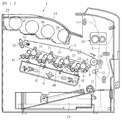
図2は、本実施形態に係る定着装置の断面図である。
図2に示すように、定着装置20は、定着部材としての定着ベルト21と、定着ベルト21の外周面に対向する対向部材としての加圧ローラ22と、定着ベルト21を加熱する加熱源としての2本のハロゲンヒータ23a,23bと、定着ベルト21の内周側に配置されたニップ形成部材24と、ニップ形成部材24を支持する支持部材としてのステー25と、各ハロゲンヒータ23a,23bから放射される熱(輻射熱)又は光を定着ベルト21へ反射する反射部材26と、主に一方のハロゲンヒータ23bから放射される熱(輻射熱)又は光を遮蔽する可動遮蔽部材27と、両方のハロゲンヒータ23a,23bから放射される熱(輻射熱)又は光を遮蔽する端部遮蔽部材としての固定遮蔽部材28と、定着ベルト21の温度を検知する温度検知手段としての温度センサ29等を備える。
FIG. 2 is a cross-sectional view of the fixing device according to the present embodiment.
As shown in FIG. 2, the fixing
上記定着ベルト21は、薄肉で可撓性を有する無端状のベルト部材(フィルムも含む)で形成される。詳しくは、定着ベルト21は、ニッケルもしくはSUS等の金属材料又はポリイミド(PI)などの樹脂材料で形成された内周側の基材と、テトラフルオロエチレン−パーフルオロアルキルビニルエーテル共重合体(PFA)又はポリテトラフルオロエチレン(PTFE)などで形成された外周側の離型層によって構成されている。基材と離型層との間に、シリコーンゴム、発泡性シリコーンゴム、又はフッ素ゴム等のゴム材料で形成された弾性層を介在させてもよい。
The fixing
弾性層が無い場合は、熱容量が小さくなり定着性の向上を達成できるが、未定着トナーを押しつぶして定着させるときにベルト表面の微小な凹凸が画像に転写されて画像のベタ部に光沢ムラを生じる可能性がある。これを防止するには、厚さ100μm以上の弾性層を設けることが望ましい。厚さ100μm以上の弾性層を設けることで、弾性層の弾性変形により微小な凹凸を吸収することができるので、光沢ムラの発生を回避することができるようになる。 If there is no elastic layer, the heat capacity becomes smaller and the fixing property can be improved, but when the unfixed toner is crushed and fixed, the minute unevenness on the belt surface is transferred to the image and the solid part of the image becomes unevenly glossy. It can occur. To prevent this, it is desirable to provide an elastic layer with a thickness of 100 μm or more. By providing an elastic layer having a thickness of 100 μm or more, it is possible to absorb minute irregularities due to elastic deformation of the elastic layer, so that it is possible to avoid the occurrence of uneven gloss.
本実施形態では、定着ベルト21の低熱容量化を図るために、定着ベルト21を薄くかつ小径化している。具体的には、定着ベルト21を構成する基材、弾性層、離型層のそれぞれの厚さを、20〜50μm、100〜300μm、10〜50μmの範囲に設定し、全体としての厚さを1mm以下に設定している。また、定着ベルト21の直径は、20〜40mmに設定している。さらに低熱容量化を図るためには、望ましくは、定着ベルト21全体の厚さを0.2mm以下にするのがよく、さらに望ましくは、0.16mm以下の厚さとするのがよい。
In the present embodiment, the fixing
加圧ローラ22は、芯金22aと、芯金22aの表面に設けられた発泡性シリコーンゴム、シリコーンゴム、又はフッ素ゴムといったゴム材料等から成る弾性層22bと、弾性層22bの表面に設けられたPFA又はPTFE等から成る離型層22cとによって構成されている。加圧ローラ22は、加圧機構によって定着ベルト21側へ加圧され、定着ベルト21を介してニップ形成部材24に当接している。この加圧ローラ22と定着ベルト21とが圧接する箇所では、加圧ローラ22の弾性層22bが押しつぶされることで、所定の幅のニップ部Nが形成されている。
The
また、加圧ローラ22は、装置本体に設けられたモータ等の駆動源によって回転駆動するように構成されている。加圧ローラ22が回転すると、その駆動力が定着ニップNで定着ベルト21に伝達され、定着ベルト21が従動回転する。
Further, the
本実施形態では、加圧ローラ22を中実のローラとしているが、中空のローラであってもよい。その場合、加圧ローラ22の内部にハロゲンヒータ等の加熱源を配置してもよい。また、弾性層22bはソリッドゴムでもよいが、加圧ローラ22の内部に加熱源が無い場合は、スポンジゴムを用いてもよい。スポンジゴムの方が、断熱性が高く、定着ベルト21の熱が奪われにくくなるのでより望ましい。
In the present embodiment, the
各ハロゲンヒータ23a,23bは、定着ベルト21の内周側に配置され、ニップ部N以外の箇所で定着ベルト21を直接加熱する。本実施形態では、各ハロゲンヒータ23a,23bが、定着ベルト21内の用紙搬送方向上流側の領域において定着ベルト21と直接対向しており、この上流側の領域において定着ベルト21は直接加熱される。
The
また、各ハロゲンヒータ23a,23bは、装置本体に設けられた電源部により出力制御されて発熱する。その出力制御は、温度センサ29による定着ベルト21の表面温度の検知結果に基づいて行われる。このようなヒータ23の出力制御によって、定着ベルト21は所望の温度(定着温度)に維持される。なお、定着ベルト21の温度を検知する温度センサの代わりに、加圧ローラ22の温度を検知する温度センサを設け、その温度センサで検知した温度により、定着ベルト21の温度を予測するようにしてもよい。
Further, each of the
用紙P上に担持された未定着画像Tを定着する際は、まず、加圧ローラ22の回転駆動を開始して定着ベルト21を従動回転させ、ハロゲンヒータ23a,23bの一方又は両方を発熱させて定着ベルト21を加熱する。そして、定着ベルト21の温度が所望の温度にまで上昇した状態で、ニップ部Nに用紙Pを通過させることにより、用紙P上の未定着画像T(トナー)が加熱されると共に加圧されて定着される。
When fixing the unfixed image T supported on the paper P, first, the rotational drive of the
ニップ形成部材24は、定着ベルト21の内側でかつ定着ベルト21を介して加圧ローラ22と対向する位置に配置されており、ステー25によって支持されている。これにより、加圧ローラ22による加圧力でニップ形成部材24に撓みが生じるのを防止し、定着ベルト21と加圧ローラ22の対向領域の軸方向全体で均一なニップ幅を形成することができる。
The
ステー25は、ニップ形成部材24の撓み防止機能を満足するために、ステンレス等の鋼材をはじめとする金属材料で形成されるが、撓み防止に十分な効果があれば樹脂材料でステー25を形成してもよい。
The
ニップ形成部材24は、耐熱性に富む樹脂材料、例えばポリエーテルサルフォン(PES)、ポリフェニレンスルフィド(PPS)、液晶ポリマー(LCP)、ポリエーテルニトリル(PEN)、ポリアミドイミド(PAI)、ポリエーテルエーテルケトン(PEEK)等で形成されている
The
また、ニップ形成部材24のニップ部N側の面には、低摩擦シート243が取り付けられている。定着ベルト21が回転すると、この低摩擦シート243に対して定着ベルト21の内周面が摺動することで、定着ベルト21に作用する摩擦抵抗の低減が図られる。なお、低摩擦シート243を省略することも可能である。
Further, a
反射部材26は、ステー25とハロゲンヒータ23a,23bとの間に配置され、ステー25に固定支持されている。この反射部材26によって、ハロゲンヒータ23a,23bからの熱を定着ベルト21へ反射することで、熱がステー25等に伝達されるのを抑制し、定着ベルト21を効率良く加熱できるようにして省エネルギー化を図っている。反射部材26の材料としては、アルミニウムやステンレス等が用いられる。特に、アルミニウム製の基材に輻射率の低い(反射率の高い)銀を蒸着したものを用いた場合、定着ベルト21の加熱効率を向上させることが可能である。
The
可動遮蔽部材27は、例えば、厚さ0.1mm〜1.0mmの金属板を、定着ベルト21の内周面に沿った円弧状の断面形状に形成して構成されている。また、可動遮蔽部材27は、定着ベルト21とハロゲンヒータ23a,23bとの間を周方向に移動可能に構成されている。一方、固定遮蔽部材28は、ステー25に固定されている。固定遮蔽部材28は、定着ベルト21の両端部側にそれぞれ配置され、各ハロゲンヒータ23a,23bの定着ベルト21側を覆っている。可動遮蔽部材27と固定遮蔽部材28はいずれも耐熱性を要するため、これらの素材には、アルミニウム、鉄、ステンレス等の金属材料、又はセラミックを用いることが好ましい。
The
図3は、本実施形態に係る定着装置の主要部の概略構成を示す斜視図である。
図3に示すように、定着ベルト21の両端部の内周側には、保持部材としてのベルト保持部材40が挿入されている。定着ベルト21は、その両端部側でベルト保持部材40によって回転可能に支持されており、基本的にベルト保持部材40以外に定着ベルト21を支持する部材は存在しない。つまり、定着ベルト21は、ローラ等に架け渡されていない無張架の状態にある。ベルト保持部材40は、ハロゲンヒータ23a,23b及びステー25と共に、定着ベルト21の軸方向両側に設けられた一対の側板に固定支持されている。
FIG. 3 is a perspective view showing a schematic configuration of a main part of the fixing device according to the present embodiment.
As shown in FIG. 3, a
図4は、定着装置のベルト保持部材が配置された一端部側の構成を示す斜視図、図5は、ベルト保持部材の斜視図である。
図4及び図5に示すように、ベルト保持部材40は、定着ベルト21を回転可能に保持する保持部401と、定着ベルト21の軸方向の寄りを規制する規制部402と、定着装置の側板39にネジなどの締結具で固定される固定部403とを有する。保持部401は、周方向の一部に開口部404を有する部分円筒状に形成されている。この保持部401が定着ベルト21の端部内に挿入されることで、定着ベルト21が保持部401によって回転可能に保持される。
FIG. 4 is a perspective view showing a configuration on one end side in which a belt holding member of the fixing device is arranged, and FIG. 5 is a perspective view of the belt holding member.
As shown in FIGS. 4 and 5, the
各部材を組み付けた状態では、保持部401の開口部404にはニップ形成部材24の端部が配置される。また、保持部401の内周側には、固定遮蔽部材28が配置される。これにより、ハロゲンヒータ23a,23bからの熱によってベルト保持部材40が過剰に温度上昇するのが抑制され、熱による変形や破損が防止される。
In the state where each member is assembled, the end portion of the
規制部402は、少なくとも定着ベルト21の外径よりも大きく形成されている。図5に示すように、定着ベルト21は、その端部が規制部402に対向した状態で配置される。そして、駆動中に定着ベルト21に軸方向への寄り移動が生じた場合は、定着ベルト21の端部が規制部402に当接することでその寄り移動が規制される。
The regulating
図6に示すように、2本のハロゲンヒータ23a,23bは、互いに発熱領域が異なるヒータで構成されている。一方のハロゲンヒータ23aは、定着ベルトの幅方向中央側に発熱部(発光部)h1を有する第1加熱源としての中央ヒータであり、他方のハロゲンヒータ23bは、定着ベルトの幅方向両端部側に発熱部(発光部)h2を有する第2加熱源としての端部ヒータである。また、端部ヒータ23bの各発熱部h2における内側端部(定着ベルト21の幅方向中央側の端部)は、中央ヒータ23aの発熱部h1の両端部に対応する位置に配置されている。以下の説明では、定着ベルト21の幅方向中央側を幅方向内側とし、幅方向端部側を幅方向外側とする。
As shown in FIG. 6, the two
中央ヒータ23a及び端部ヒータ23bはハロゲンヒータであり、円筒状の管状部材としてのガラス管50と、ガラス管50内に挿入された発熱体としてのフィラメント51を有する。このフィラメント51が長手方向に渡って連続して密に巻かれた密巻部により各発熱部h1,h2が構成される。
The
ハロゲンヒータ23a、23bの発熱部h1、h2以外の部分の主たる発熱部分ではない周辺部h0においては、フィラメント51が略直線状に形成されている。この周辺部h0にも、「捨て巻」と呼ばれるフィラメント51が部分的に密に巻かれた密巻部53が存在し、環状のサポータ52によって保持されている。密巻部53がサポータ52によって保持されることで、フィラメント51がその全体の形状を維持することができる。周辺部h0では、密巻部53および直線状に形成されたフィラメント51からわずかな発熱がある。またサポータ52は、タングステン等で構成され、発熱部h1,h2にも配置されている。
The
ハロゲンヒータ23a、23bの各ガラス管50は、その幅方向両端に封止部55を有する。封止部55は、ガラス管50の径が幅方向外側へ向かうに従って細く絞られて小さくなっていき、ガラス管50の幅方向端部においてその内部を封止する部分である(ただし、リード線に接続される端部までを含めて封止部としてもよい)。封止部55は、その径が小さいため、ガラス管50のその他の部分に比べて強度的に弱く、熱劣化の影響等により破損しやすい。
Each of the
以上の定着装置においては、定着装置に通紙される用紙の幅サイズに応じて加熱範囲が変更される。つまり、定着装置に通紙される用紙の幅サイズが小さい場合には、中央ヒータ23aの発熱部h1のみが発熱し、通紙される用紙の幅サイズが大きい場合には、これに加えて端部ヒータ23bの発熱部h2が発熱する。
In the above fixing device, the heating range is changed according to the width size of the paper passed through the fixing device. That is, when the width size of the paper to be passed through the fixing device is small, only the heat generating portion h1 of the
しかし、定着装置に通紙される用紙の幅サイズは様々であるため、上記の発熱部h2の発熱の有無のみでは多様な用紙の幅サイズに対応することはできず、定着ベルトの加熱範囲と用紙幅が一致しないことがある。そして、定着装置に通紙される用紙サイズがハロゲンヒータ23a、23bによる加熱範囲よりも小さい場合、主に定着ベルト21の幅方向端部が非通紙領域となる。この非通紙領域では、定着ベルト21から熱が奪われないため、定着ベルト21の幅方向端部における非通紙領域やその周辺部材において、特に温度が上昇しやすくなっている。
However, since the width size of the paper passed through the fixing device varies, it is not possible to correspond to various width sizes of the paper only by the presence or absence of heat generated by the heat generating portion h2, and the heating range of the fixing belt Paper widths may not match. When the size of the paper passed through the fixing device is smaller than the heating range of the
さらに、上記のハロゲンヒータ23a、23bからの輻射熱に加えて、本実施形態の定着装置には、定着ベルト21を効率よく加熱するために反射部材26が設けられている。反射部材26が設けられることにより、定着ベルト21やその周辺部材は、反射部材26による反射熱を受けることによってもその温度が上昇する。
Further, in addition to the radiant heat from the
以上のハロゲンヒータ23a、23bからの輻射熱と反射部材26の反射熱によって、特に定着ベルト21の幅方向端部において、定着ベルト21の周辺に設けられた各部材が過剰に温度上昇し、経時的に部材の熱劣化や破損を生じる虞があり、その対策が必要である。
Due to the radiant heat from the
さらに、本実施形態の反射部材26は、中央ヒータ23a及び端部ヒータ23bの側へ折り曲げて設けられており、反射部材26は、これらのヒータを定着ベルト21の周方向に覆う様に設けられる(図2参照)。これにより、ハロゲンヒータ23a、23bの発熱部h1、h2からの輻射熱を狭い範囲に集約させ、効率よく定着ベルト21の側へ反射させることができる。しかし一方で、反射部材26の各面が屈曲していることで、反射部材26に到達した熱が屈曲面に反射して乱反射する。そして、この乱反射した反射熱により、発熱部h1、h2の加熱領域を超えて各部材が熱せられたり、過剰に加熱されたりする場合があり、上記の問題が特に発生しやすい。
Further, the
本実施形態の定着装置においては、反射部材と周辺部材を適当な位置関係で配置することにより、反射部材の反射熱から周辺部材を保護し、上記の問題を解決することができる。以下の図7で、反射部材と定着ベルト周辺に設けられた各部材の配置について説明する。図7は、各部材を簡略化して示し、各部材の幅方向の位置関係を示した概略図である。また、ハロゲンヒータの幅方向位置を規制する構造については、後述する図8で説明する。 In the fixing device of the present embodiment, by arranging the reflective member and the peripheral member in an appropriate positional relationship, the peripheral member can be protected from the reflected heat of the reflective member, and the above problem can be solved. In FIG. 7 below, the arrangement of the reflective member and each member provided around the fixing belt will be described. FIG. 7 is a simplified view showing the positional relationship of each member in the width direction. Further, a structure for restricting the position of the halogen heater in the width direction will be described with reference to FIG. 8 to be described later.
図7に示すように、定着ベルト21の幅方向外側端部には、ベルト保持部材40や固定遮蔽部材28等の各部材が配置される。反射部材26は、中央ヒータ23a及び端部ヒータ23bの輻射熱を反射して定着ベルト21を効率よく加熱するために、ハロゲンヒータ23a、23bに対向して、定着ベルト21の幅方向端部側から中央側にわたって設けられている。
As shown in FIG. 7, each member such as the
ハロゲンヒータ23a、23bの封止部55よりも幅方向外側には、二つのハロゲンヒータの両端を保持するコネクタ部56が設けられる。コネクタ部56にはリード線57が接続されており、リード線57がコネクタ部56よりも幅方向の外側に向かって延在している。コネクタ部56の径は、ハロゲンヒータ23a、23bよりも大きく設けられ、二つのハロゲンヒータをその内側に保持している。
A
本実施形態では、ハロゲンヒータ23a、23bの封止部55(封止部55の幅方向内側端部55in)が、反射部材26の幅方向外側端部26outよりも幅方向外側に設けられる。これにより、反射部材26によって反射された熱が封止部55に到達しにくくなる。前述の様に、封止部55はガラス管の中で特に強度が弱い部分であるため、反射熱により繰り返し高温状態になると、経時的に破損する虞がある。しかし、本実施形態の構成によって封止部55が高温状態になることを回避して封止部55を熱劣化から保護し、封止部55におけるガラス管の亀裂等の破損を防止することができる。
In the present embodiment, the sealing
また、ベルト保持部材40の幅方向内側端部40inは、反射部材26の幅方向外側端部26outよりも外側に設けられる。これにより、ベルト保持部材40(あるいは、これに対向して設けられる固定遮蔽部材28)に反射部材26による反射熱が到達しにくくなる。
Further, the widthwise inner end portion 40in of the
従来の定着装置では、上記の反射熱の影響を考慮した場合、ベルト保持部材40には耐熱性の材料(例えば金属材料)を用いる必要がある。しかし、本実施形態では、上記の様にベルト保持部材40(あるいは、それを保護する固定遮蔽部材28)が反射熱を受けにくくすることにより、ベルト保持部材40として樹脂材料(特に耐熱性の低い樹脂材料)を選択することができる。これにより、部材の選択の幅が広がり、コストダウンを図ることが可能になる。また、ベルト保持部材40に金属材料等の剛性の高い部材を用いた場合、定着ベルトの摩耗等が課題となるが、ベルト保持部材40に樹脂材料を用いることで定着ベルトの摩耗も防止できる。
In the conventional fixing device, it is necessary to use a heat-resistant material (for example, a metal material) for the
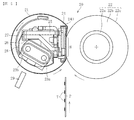
図8は、定着装置の幅方向一方側において、ハロゲンヒータ23a、23bの幅方向の移動を規制する規制部材58を示した図である。
FIG. 8 is a diagram showing a regulating
規制部材58は、側板39の一方側の面で、固定部403(図4参照)が配置される側とは反対側の面に固定部581を有し、固定部581はネジなどの締結具59で側板39に固定されている。また規制部材58は、固定部581よりも幅方向外側に貫通孔58aを備えた規制部582を有する。
The regulating
規制部材58の貫通孔58aにコネクタ部56が挿入されている。コネクタ部56は、規制部582よりも幅方向外側に、ハロゲンヒータ等の径方向へ突出したリブ56aを有する。リブ56aは、貫通孔58aの大きさを超えて径方向に突出して設けられており、コネクタ部56の規制部材58に対する他方側(図の右側)への相対移動により、規制部582に当接する。よって、コネクタ部56は、リブ56aが規制部材58に当接する位置で幅方向の他方側への移動が規制されており、ハロゲンヒータ23a、23bの規制部材58や側板39に対する幅方向位置が規制されている。
The
また、図8で示した側とは反対側(他方側)の幅方向外側においても、コネクタ部56が規制部材58により保持される。ただし、他方側のコネクタ部56はリブ56aを有しておらず、その幅方向位置が規制されているわけではない。ハロゲンヒータ23a、23bの幅方向位置をその両側で規制してしまうと、ハロゲンヒータ23a、23bの発熱等によってコネクタ部56やハロゲンヒータ23a、23bが熱膨張した場合に、その膨張分を逃がすことができず、部品の破損の虞がある。しかし、本実施形態では、幅方向の一方側にのみリブ56aを設けて幅方向位置を規制することで、コネクタ部56やハロゲンヒータ23a、23が熱膨張した場合でも、その膨張分を他方側へ延出させることができ、部材の破損を防止できる。また、ハロゲンヒータ23a、23bの一方側の幅方向位置を規制し、熱膨張による延出方向を他方側に限定することで、ハロゲンヒータ23a、23bの一方側から見た各部材との位置関係が、部材の熱膨張によってずれにくくなり、前述の図7で示した封止部55やベルト保持部材40と反射部材26との位置関係を保つことができる。
Further, the
上記の実施形態と異なるハロゲンヒータとして、図9に示すハロゲンヒータを中央ヒータ23aとして用いることができる。図9に示す中央ヒータ23aでは、中央に設けられる発熱部h1の構成は上記の実施形態と同様であるが、発熱部h1の両側に設けられた周辺部h0が、芯部材としての短絡用芯棒54にフィラメント51が巻き付けられた構成をしている。短絡用芯棒54は、モリブデン等の電気抵抗の小さい部材によって形成され、フィラメント51よりも電気抵抗が小さい。幅方向に設けられた棒状部材である短絡用芯棒54にフィラメント51を巻き付けることにより、ガラス管50内でフィラメント51の形状を維持することができる。
As the halogen heater different from the above embodiment, the halogen heater shown in FIG. 9 can be used as the
この中央ヒータ23aでは、周辺部h0に短絡用芯棒54を設けることで、図9に示した周辺部h0に密巻部53を設ける構成の中央ヒータ23aと比較して、周辺部h0全体としての電気抵抗が小さくなり、周辺部h0における発熱を抑制することができる。これにより、前述の定着ベルトの幅方向端部における定着ベルトや周辺部材の温度上昇を抑制することができ、前述の図7で示した反射部材26の配置と併用することで、より確実にガラス管50の封止部55やベルト保持部材40の過剰な温度上昇を防止することができる。
In this
本実施形態では、ハロゲンヒータは2本設けられているが、図10に示す様なハロゲンヒータ23が一本の定着装置であってもよいし、プリンタで使用する用紙のサイズ等に応じて、図11で示すようなハロゲンヒータが3本、あるいはそれ以上設けられた定着装置であってもよい。この場合でも、反射部材26と封止部55あるいはベルト保持部材40との位置関係を前述と同様に設けることで、上記の実施形態と同様の効果を得ることができる。
In the present embodiment, two halogen heaters are provided, but the
以上、本発明について説明したが、本発明は、上述の実施形態に限らず、本発明の要旨を逸脱しない範囲で種々の変更を加え得ることは勿論である。本発明に係る定着装置を搭載する画像形成装置は、図1に示すようなカラープリンタに限らず、モノクロプリンタであってもよい。また、プリンタに限らず、複写機、ファクシミリ、あるいはこれらの複合機等であってもよい。 Although the present invention has been described above, the present invention is not limited to the above-described embodiment, and it goes without saying that various modifications can be made without departing from the gist of the present invention. The image forming apparatus equipped with the fixing apparatus according to the present invention is not limited to the color printer as shown in FIG. 1, and may be a monochrome printer. Further, the present invention is not limited to a printer, and may be a copying machine, a facsimile, a multifunction device thereof, or the like.
20 定着装置
21 定着ベルト(定着部材)
23a 中央ヒータ(加熱源)
23b 端部ヒータ(加熱源)
26 反射部材
28 固定遮蔽部材(端部遮蔽部材)
40 ベルト保持部材(保持部材)
50 ガラス管(管状部材)
51 フィラメント(発熱体)
54 短絡用芯棒(芯部材)
55 封止部
58 規制部材
h0 周辺部
h1、h2 発熱部
N ニップ部
20
23a Central heater (heat source)
23b End heater (heat source)
26
40 Belt holding member (holding member)
50 Glass tube (tubular member)
51 Filament (heating element)
54 Short-circuit core rod (core member)
55 Sealing
Claims (9)
前記定着部材を加熱する加熱源と、
前記定着部材の幅方向端部側から中央側にわたって設けられ、前記加熱源からの輻射熱を前記定着部材に向けて反射する反射部材と、
前記加熱源の幅方向の移動を規制する規制部材と、
前記定着部材を回転可能に保持する保持部材と、
前記保持部材を支持し、前記保持部材を介して前記定着部材の幅方向両側を支持する側板とを有する定着装置であって、
前記加熱源は、管状部材と、前記管状部材の内部に設けられた発熱体とを有し、
前記管状部材は、前記管状部材の径が絞られた封止部を有し、
前記定着部材の幅方向中央側を幅方向内側とし、幅方向端部側を幅方向外側としたとき、前記封止部の幅方向内側端部は、前記反射部材の幅方向外側端部よりも幅方向外側に設けられ、
前記加熱源はさらに、前記管状部材の幅方向端部側の外表面をその外側から保持する保持部を有し、
前記封止部は、前記管状部材の幅方向両端部側であって、前記管状部材の前記保持部に保持される部分よりも幅方向内側に設けられ、
前記規制部材は、前記側板に取り付けられる固定部と、前記固定部よりも幅方向外側に設けられた規制部とを有し、
前記保持部は、前記規制部に前記加熱源の幅方向外側から当接する当接部を有し、
前記当接部の前記規制部に対する当接位置は、前記反射部材の幅方向外側端部よりも幅方向外側に設けられることを特徴とする定着装置。 With a rotatable fixing member,
A heating source for heating the fixing member and
A reflective member provided from the widthwise end side to the center side of the fixing member and reflecting radiant heat from the heating source toward the fixing member.
A regulatory member that regulates the movement of the heating source in the width direction, and
A holding member that rotatably holds the fixing member and
A fixing device having side plates that support the holding member and support both sides of the fixing member in the width direction via the holding member.
The heating source has a tubular member and a heating element provided inside the tubular member.
The tubular member has a sealing portion having a reduced diameter of the tubular member.
When the center side in the width direction of the fixing member is the inner side in the width direction and the end side in the width direction is the outer side in the width direction, the inner end portion in the width direction of the sealing portion is larger than the outer end portion in the width direction of the reflective member. Provided on the outside in the width direction
The heating source further has a holding portion that holds the outer surface of the tubular member on the widthwise end side from the outside.
The sealing portion is provided on both ends in the width direction of the tubular member and is provided inside in the width direction of the portion held by the holding portion of the tubular member.
The regulating member has a fixing portion attached to the side plate and a regulating portion provided outside the fixing portion in the width direction.
The holding portion has an abutting portion that abuts on the restricting portion from the outside in the width direction of the heating source.
A fixing device characterized in that the contact position of the contact portion with respect to the regulation portion is provided on the outer side in the width direction of the outer end portion in the width direction of the reflective member.
前記発熱部は、発熱体としてのフィラメントが前記加熱源の幅方向に渡って連続して密に巻かれた密巻部により形成され、
前記周辺部は、前記加熱源の幅方向に渡って設けられる芯部材に前記フィラメントが巻き付けられて形成され、
前記芯部材は、前記フィラメントよりも電気抵抗が小さい請求項1から5いずれか1項に記載の定着装置。 The heating source has a heat generating portion mainly for heating the fixing member provided on the center side in the width direction thereof, and a peripheral portion provided on the end portion side which is not the main heat generating portion.
The heat generating portion is formed by a tightly wound portion in which a filament as a heating element is continuously and tightly wound over the width direction of the heating source.
The peripheral portion is formed by winding the filament around a core member provided over the width direction of the heating source.
The fixing device according to any one of claims 1 to 5, wherein the core member has a smaller electric resistance than the filament.
前記保持部は前記開口部に挿入される請求項1から7いずれか1項に記載の定着装置。 The regulatory member has an opening and
The fixing device according to any one of claims 1 to 7, wherein the holding portion is inserted into the opening.
Priority Applications (6)
| Application Number | Priority Date | Filing Date | Title |
|---|---|---|---|
| JP2016034117A JP6983489B2 (en) | 2016-02-25 | 2016-02-25 | Fixing device and image forming device |
| US15/410,179 US10156818B2 (en) | 2016-02-25 | 2017-01-19 | Fixing device and image forming apparatus |
| US16/185,091 US10678170B2 (en) | 2016-02-25 | 2018-11-09 | Fixing device and image forming apparatus |
| JP2021125711A JP7153248B2 (en) | 2016-02-25 | 2021-07-30 | Fixing device and image forming device |
| JP2022156489A JP2022173463A (en) | 2016-02-25 | 2022-09-29 | Fixing device and image forming apparatus |
| JP2023216982A JP2024019683A (en) | 2016-02-25 | 2023-12-22 | Fixing device and image forming device |
Applications Claiming Priority (1)
| Application Number | Priority Date | Filing Date | Title |
|---|---|---|---|
| JP2016034117A JP6983489B2 (en) | 2016-02-25 | 2016-02-25 | Fixing device and image forming device |
Related Child Applications (1)
| Application Number | Title | Priority Date | Filing Date |
|---|---|---|---|
| JP2021125711A Division JP7153248B2 (en) | 2016-02-25 | 2021-07-30 | Fixing device and image forming device |
Publications (3)
| Publication Number | Publication Date |
|---|---|
| JP2017151286A JP2017151286A (en) | 2017-08-31 |
| JP2017151286A5 JP2017151286A5 (en) | 2018-03-22 |
| JP6983489B2 true JP6983489B2 (en) | 2021-12-17 |
Family
ID=59680048
Family Applications (4)
| Application Number | Title | Priority Date | Filing Date |
|---|---|---|---|
| JP2016034117A Active JP6983489B2 (en) | 2016-02-25 | 2016-02-25 | Fixing device and image forming device |
| JP2021125711A Active JP7153248B2 (en) | 2016-02-25 | 2021-07-30 | Fixing device and image forming device |
| JP2022156489A Pending JP2022173463A (en) | 2016-02-25 | 2022-09-29 | Fixing device and image forming apparatus |
| JP2023216982A Pending JP2024019683A (en) | 2016-02-25 | 2023-12-22 | Fixing device and image forming device |
Family Applications After (3)
| Application Number | Title | Priority Date | Filing Date |
|---|---|---|---|
| JP2021125711A Active JP7153248B2 (en) | 2016-02-25 | 2021-07-30 | Fixing device and image forming device |
| JP2022156489A Pending JP2022173463A (en) | 2016-02-25 | 2022-09-29 | Fixing device and image forming apparatus |
| JP2023216982A Pending JP2024019683A (en) | 2016-02-25 | 2023-12-22 | Fixing device and image forming device |
Country Status (2)
| Country | Link |
|---|---|
| US (2) | US10156818B2 (en) |
| JP (4) | JP6983489B2 (en) |
Cited By (1)
| Publication number | Priority date | Publication date | Assignee | Title |
|---|---|---|---|---|
| JP2021167983A (en) * | 2016-02-25 | 2021-10-21 | 株式会社リコー | Fixing device and image forming apparatus |
Families Citing this family (8)
| Publication number | Priority date | Publication date | Assignee | Title |
|---|---|---|---|---|
| JP6794155B2 (en) * | 2016-06-30 | 2020-12-02 | キヤノン株式会社 | Fixing device |
| CN110870382A (en) * | 2017-10-25 | 2020-03-06 | 惠普深蓝有限责任公司 | Heat source |
| JP7240627B2 (en) | 2019-01-31 | 2023-03-16 | 株式会社リコー | Heating body, fixing device and image forming device |
| JP7377430B2 (en) * | 2019-03-12 | 2023-11-10 | 株式会社リコー | Fixing device and image forming device |
| JP7352853B2 (en) | 2019-08-09 | 2023-09-29 | 株式会社リコー | Fixing device and image forming device |
| JP7378701B2 (en) | 2019-11-29 | 2023-11-14 | 株式会社リコー | Fixing device and image forming device |
| US11448988B2 (en) | 2020-05-19 | 2022-09-20 | Ricoh Company, Ltd. | Fixing device and image forming apparatus |
| JP2023008286A (en) | 2021-07-05 | 2023-01-19 | 株式会社リコー | Contact and separation device, fixing device, and image forming apparatus |
Family Cites Families (43)
| Publication number | Priority date | Publication date | Assignee | Title |
|---|---|---|---|---|
| JP2861280B2 (en) | 1990-06-11 | 1999-02-24 | キヤノン株式会社 | Heating equipment |
| JP2965232B2 (en) * | 1992-09-17 | 1999-10-18 | シャープ株式会社 | Fixing device |
| US5933695A (en) * | 1998-08-03 | 1999-08-03 | Xerox Corporation | Rapid wake up fuser system members with silicone layer |
| DE10056939C2 (en) | 1999-11-19 | 2003-02-20 | Hitachi Koki Kk | Lamp holder and lamp cartridge using the holder, and fuser using the holder |
| JP4035680B2 (en) * | 1999-11-19 | 2008-01-23 | リコープリンティングシステムズ株式会社 | Fixing apparatus and printing apparatus using the same |
| JP3873635B2 (en) * | 2001-03-02 | 2007-01-24 | ウシオ電機株式会社 | Heater lamp device for heating roller |
| US6960203B2 (en) * | 2002-06-26 | 2005-11-01 | Ethicon, Inc. | Thermal ablation with deployable cage |
| JP2004286922A (en) | 2003-03-20 | 2004-10-14 | Minolta Co Ltd | Belt fixing device |
| JP2005196054A (en) * | 2004-01-09 | 2005-07-21 | Sharp Corp | Image forming apparatus and fixing mechanism part controlling method |
| JP4818826B2 (en) | 2006-06-19 | 2011-11-16 | 株式会社リコー | Fixing apparatus and image forming apparatus |
| JP5245551B2 (en) * | 2008-06-06 | 2013-07-24 | ウシオ電機株式会社 | Heating device |
| JP2010026256A (en) | 2008-07-18 | 2010-02-04 | Panasonic Corp | Fixing device |
| JP2010032625A (en) | 2008-07-25 | 2010-02-12 | Panasonic Corp | Fixing device |
| JP2010107720A (en) * | 2008-10-30 | 2010-05-13 | Harison Toshiba Lighting Corp | Tubular heater device, and toner fixing device |
| JP2011095540A (en) | 2009-10-30 | 2011-05-12 | Brother Industries Ltd | Fixing device |
| JP5556236B2 (en) | 2010-02-26 | 2014-07-23 | 株式会社リコー | Fixing device and image forming apparatus having the same |
| JP5263206B2 (en) | 2010-03-25 | 2013-08-14 | ブラザー工業株式会社 | Fixing device |
| JP5471911B2 (en) * | 2010-07-07 | 2014-04-16 | 株式会社リコー | Fixing apparatus and image forming apparatus having the same |
| JP6066550B2 (en) * | 2011-11-29 | 2017-01-25 | キヤノン株式会社 | Image heating device |
| JP5796714B2 (en) * | 2012-01-13 | 2015-10-21 | 株式会社リコー | Fixing apparatus and image forming apparatus |
| JP5761524B2 (en) | 2012-01-13 | 2015-08-12 | 株式会社リコー | Fixing apparatus and image forming apparatus |
| JP5812425B2 (en) * | 2012-02-09 | 2015-11-11 | 株式会社リコー | Fixing apparatus and image forming apparatus |
| US9026024B2 (en) | 2012-02-09 | 2015-05-05 | Ricoh Company, Ltd. | Fixing device capable of minimizing damage of endless rotary body and image forming apparatus incorporating same |
| US9229379B2 (en) | 2012-09-11 | 2016-01-05 | Ricoh Company, Limited | Fixing device and image forming apparatus |
| US9046838B2 (en) | 2012-09-14 | 2015-06-02 | Ricoh Company, Ltd. | Fixing device and image forming apparatus |
| JP2014164045A (en) | 2013-02-22 | 2014-09-08 | Brother Ind Ltd | Fixing apparatus and image forming apparatus |
| JP6047857B2 (en) | 2013-03-15 | 2016-12-21 | 株式会社リコー | Fixing apparatus and image forming apparatus |
| JP6236815B2 (en) | 2013-03-15 | 2017-11-29 | 株式会社リコー | Fixing apparatus and image forming apparatus |
| JP6210267B2 (en) | 2013-03-15 | 2017-10-11 | 株式会社リコー | Fixing apparatus and image forming apparatus |
| JP2014186211A (en) | 2013-03-25 | 2014-10-02 | Ricoh Co Ltd | Fixing device and image forming apparatus |
| JP6221546B2 (en) | 2013-05-14 | 2017-11-01 | 株式会社リコー | Fixing apparatus and image forming apparatus |
| JP6070990B2 (en) | 2013-05-14 | 2017-02-01 | 株式会社リコー | Fixing apparatus and image forming apparatus |
| JP5907358B2 (en) * | 2013-05-16 | 2016-04-26 | 株式会社リコー | Fixing apparatus and image forming apparatus |
| JP2014235308A (en) | 2013-05-31 | 2014-12-15 | 株式会社リコー | Fixing device and image forming apparatus |
| JP6086100B2 (en) | 2013-08-26 | 2017-03-01 | 株式会社リコー | Fixing apparatus and image forming apparatus |
| JP2015075525A (en) | 2013-10-07 | 2015-04-20 | 株式会社リコー | Fixing device and image forming apparatus |
| JP6063849B2 (en) | 2013-10-16 | 2017-01-18 | 京セラドキュメントソリューションズ株式会社 | Fixing apparatus and image forming apparatus |
| JP2015082075A (en) | 2013-10-24 | 2015-04-27 | ウシオ電機株式会社 | Toner fixing filament lamp with base |
| JP6134288B2 (en) | 2014-03-31 | 2017-05-24 | 京セラドキュメントソリューションズ株式会社 | Fixing apparatus and image forming apparatus |
| JP6210086B2 (en) * | 2015-05-08 | 2017-10-11 | コニカミノルタ株式会社 | Image forming apparatus |
| US9874839B2 (en) | 2015-06-23 | 2018-01-23 | Ricoh Company, Ltd. | Fixing device and image forming apparatus |
| JP6583716B2 (en) | 2015-07-07 | 2019-10-02 | 株式会社リコー | Fixing apparatus and image forming apparatus |
| JP6983489B2 (en) | 2016-02-25 | 2021-12-17 | 株式会社リコー | Fixing device and image forming device |
-
2016
- 2016-02-25 JP JP2016034117A patent/JP6983489B2/en active Active
-
2017
- 2017-01-19 US US15/410,179 patent/US10156818B2/en active Active
-
2018
- 2018-11-09 US US16/185,091 patent/US10678170B2/en active Active
-
2021
- 2021-07-30 JP JP2021125711A patent/JP7153248B2/en active Active
-
2022
- 2022-09-29 JP JP2022156489A patent/JP2022173463A/en active Pending
-
2023
- 2023-12-22 JP JP2023216982A patent/JP2024019683A/en active Pending
Cited By (2)
| Publication number | Priority date | Publication date | Assignee | Title |
|---|---|---|---|---|
| JP2021167983A (en) * | 2016-02-25 | 2021-10-21 | 株式会社リコー | Fixing device and image forming apparatus |
| JP7153248B2 (en) | 2016-02-25 | 2022-10-14 | 株式会社リコー | Fixing device and image forming device |
Also Published As
| Publication number | Publication date |
|---|---|
| US10156818B2 (en) | 2018-12-18 |
| JP2022173463A (en) | 2022-11-18 |
| JP7153248B2 (en) | 2022-10-14 |
| US10678170B2 (en) | 2020-06-09 |
| JP2017151286A (en) | 2017-08-31 |
| JP2024019683A (en) | 2024-02-09 |
| US20170248879A1 (en) | 2017-08-31 |
| US20190094764A1 (en) | 2019-03-28 |
| JP2021167983A (en) | 2021-10-21 |
Similar Documents
| Publication | Publication Date | Title |
|---|---|---|
| JP6983489B2 (en) | Fixing device and image forming device | |
| JP5737531B2 (en) | Fixing apparatus and image forming apparatus | |
| JP5796714B2 (en) | Fixing apparatus and image forming apparatus | |
| JP5928783B2 (en) | Fixing apparatus and image forming apparatus | |
| JP6176437B2 (en) | Fixing apparatus and image forming apparatus | |
| JP5963105B2 (en) | Fixing apparatus and image forming apparatus | |
| JP6150107B2 (en) | Fixing apparatus and image forming apparatus | |
| JP6464782B2 (en) | Fixing apparatus and image forming apparatus | |
| JP6551813B2 (en) | Fixing apparatus and image forming apparatus | |
| JP6252822B2 (en) | Fixing apparatus and image forming apparatus | |
| JP6106920B2 (en) | Fixing apparatus and image forming apparatus | |
| JP6855763B2 (en) | Fixing device and image forming device | |
| JP6432853B2 (en) | Fixing apparatus and image forming apparatus | |
| JP6650107B2 (en) | Fixing device and image forming device | |
| JP6859994B2 (en) | Fixing device and image forming device | |
| JP6826774B2 (en) | Fixing device and image forming device | |
| JP6213890B2 (en) | Fixing apparatus and image forming apparatus | |
| JP6128368B2 (en) | Fixing apparatus and image forming apparatus | |
| JP5880765B2 (en) | Fixing apparatus and image forming apparatus | |
| JP6168463B2 (en) | Fixing apparatus and image forming apparatus | |
| JP6103262B2 (en) | Fixing apparatus and image forming apparatus | |
| JP2017199604A (en) | Filament lamp, fixing device, and image forming device | |
| JP2015129977A (en) | Fixing device and image forming apparatus | |
| JP5930281B2 (en) | Fixing apparatus and image forming apparatus | |
| JP2021002001A (en) | Fixing device and image forming apparatus |
Legal Events
| Date | Code | Title | Description |
|---|---|---|---|
| A521 | Request for written amendment filed |
Free format text: JAPANESE INTERMEDIATE CODE: A523 Effective date: 20180208 |
|
| A621 | Written request for application examination |
Free format text: JAPANESE INTERMEDIATE CODE: A621 Effective date: 20190109 |
|
| A977 | Report on retrieval |
Free format text: JAPANESE INTERMEDIATE CODE: A971007 Effective date: 20191010 |
|
| A131 | Notification of reasons for refusal |
Free format text: JAPANESE INTERMEDIATE CODE: A131 Effective date: 20191017 |
|
| A521 | Request for written amendment filed |
Free format text: JAPANESE INTERMEDIATE CODE: A523 Effective date: 20191216 |
|
| A131 | Notification of reasons for refusal |
Free format text: JAPANESE INTERMEDIATE CODE: A131 Effective date: 20200107 |
|
| A521 | Request for written amendment filed |
Free format text: JAPANESE INTERMEDIATE CODE: A523 Effective date: 20200303 |
|
| A02 | Decision of refusal |
Free format text: JAPANESE INTERMEDIATE CODE: A02 Effective date: 20200316 |
|
| A521 | Request for written amendment filed |
Free format text: JAPANESE INTERMEDIATE CODE: A523 Effective date: 20200612 |
|
| C60 | Trial request (containing other claim documents, opposition documents) |
Free format text: JAPANESE INTERMEDIATE CODE: C60 Effective date: 20200612 |
|
| C11 | Written invitation by the commissioner to file amendments |
Free format text: JAPANESE INTERMEDIATE CODE: C11 Effective date: 20200622 |
|
| A521 | Request for written amendment filed |
Free format text: JAPANESE INTERMEDIATE CODE: A523 Effective date: 20200629 |
|
| A911 | Transfer to examiner for re-examination before appeal (zenchi) |
Free format text: JAPANESE INTERMEDIATE CODE: A911 Effective date: 20200701 |
|
| C21 | Notice of transfer of a case for reconsideration by examiners before appeal proceedings |
Free format text: JAPANESE INTERMEDIATE CODE: C21 Effective date: 20200702 |
|
| A912 | Re-examination (zenchi) completed and case transferred to appeal board |
Free format text: JAPANESE INTERMEDIATE CODE: A912 Effective date: 20200722 |
|
| C211 | Notice of termination of reconsideration by examiners before appeal proceedings |
Free format text: JAPANESE INTERMEDIATE CODE: C211 Effective date: 20200728 |
|
| C22 | Notice of designation (change) of administrative judge |
Free format text: JAPANESE INTERMEDIATE CODE: C22 Effective date: 20201202 |
|
| C13 | Notice of reasons for refusal |
Free format text: JAPANESE INTERMEDIATE CODE: C13 Effective date: 20210601 |
|
| A521 | Request for written amendment filed |
Free format text: JAPANESE INTERMEDIATE CODE: A523 Effective date: 20210728 |
|
| C13 | Notice of reasons for refusal |
Free format text: JAPANESE INTERMEDIATE CODE: C13 Effective date: 20210902 |
|
| A521 | Request for written amendment filed |
Free format text: JAPANESE INTERMEDIATE CODE: A523 Effective date: 20210907 |
|
| C302 | Record of communication |
Free format text: JAPANESE INTERMEDIATE CODE: C302 Effective date: 20210907 |
|
| C23 | Notice of termination of proceedings |
Free format text: JAPANESE INTERMEDIATE CODE: C23 Effective date: 20211006 |
|
| C03 | Trial/appeal decision taken |
Free format text: JAPANESE INTERMEDIATE CODE: C03 Effective date: 20211104 |
|
| C30A | Notification sent |
Free format text: JAPANESE INTERMEDIATE CODE: C3012 Effective date: 20211104 |
|
| A61 | First payment of annual fees (during grant procedure) |
Free format text: JAPANESE INTERMEDIATE CODE: A61 Effective date: 20211124 |
|
| R150 | Certificate of patent or registration of utility model |
Ref document number: 6983489 Country of ref document: JP Free format text: JAPANESE INTERMEDIATE CODE: R150 |