JP6983480B2 - Two-way catalytic system for boiling bed improvement to produce improved quality decompression residual oil products - Google Patents
Two-way catalytic system for boiling bed improvement to produce improved quality decompression residual oil products Download PDFInfo
- Publication number
- JP6983480B2 JP6983480B2 JP2018563559A JP2018563559A JP6983480B2 JP 6983480 B2 JP6983480 B2 JP 6983480B2 JP 2018563559 A JP2018563559 A JP 2018563559A JP 2018563559 A JP2018563559 A JP 2018563559A JP 6983480 B2 JP6983480 B2 JP 6983480B2
- Authority
- JP
- Japan
- Prior art keywords
- initial
- bottom product
- quality
- catalyst
- boiling bed
- Prior art date
- Legal status (The legal status is an assumption and is not a legal conclusion. Google has not performed a legal analysis and makes no representation as to the accuracy of the status listed.)
- Active
Links
- 238000009835 boiling Methods 0.000 title claims description 226
- 230000006837 decompression Effects 0.000 title claims description 67
- 230000003197 catalytic effect Effects 0.000 title description 51
- 230000006872 improvement Effects 0.000 title description 17
- 239000003054 catalyst Substances 0.000 claims description 234
- 239000003921 oil Substances 0.000 claims description 211
- 239000000047 product Substances 0.000 claims description 196
- 239000000295 fuel oil Substances 0.000 claims description 133
- UFHFLCQGNIYNRP-UHFFFAOYSA-N Hydrogen Chemical compound [H][H] UFHFLCQGNIYNRP-UHFFFAOYSA-N 0.000 claims description 99
- 238000000034 method Methods 0.000 claims description 95
- 238000006243 chemical reaction Methods 0.000 claims description 94
- 239000002245 particle Substances 0.000 claims description 94
- 229910052739 hydrogen Inorganic materials 0.000 claims description 83
- 239000001257 hydrogen Substances 0.000 claims description 83
- 230000002829 reductive effect Effects 0.000 claims description 83
- 229910052976 metal sulfide Inorganic materials 0.000 claims description 74
- 238000011282 treatment Methods 0.000 claims description 71
- 239000012018 catalyst precursor Substances 0.000 claims description 69
- 229930195733 hydrocarbon Natural products 0.000 claims description 62
- 150000002430 hydrocarbons Chemical class 0.000 claims description 61
- 239000002638 heterogeneous catalyst Substances 0.000 claims description 59
- 239000000203 mixture Substances 0.000 claims description 55
- NINIDFKCEFEMDL-UHFFFAOYSA-N Sulfur Chemical compound [S] NINIDFKCEFEMDL-UHFFFAOYSA-N 0.000 claims description 52
- 229910052717 sulfur Inorganic materials 0.000 claims description 52
- 239000011593 sulfur Substances 0.000 claims description 52
- 230000009977 dual effect Effects 0.000 claims description 50
- 239000004215 Carbon black (E152) Substances 0.000 claims description 44
- 239000002243 precursor Substances 0.000 claims description 39
- 238000002156 mixing Methods 0.000 claims description 37
- OKTJSMMVPCPJKN-UHFFFAOYSA-N Carbon Chemical compound [C] OKTJSMMVPCPJKN-UHFFFAOYSA-N 0.000 claims description 35
- 229910052799 carbon Inorganic materials 0.000 claims description 35
- 230000005484 gravity Effects 0.000 claims description 34
- 239000013049 sediment Substances 0.000 claims description 27
- 239000008186 active pharmaceutical agent Substances 0.000 claims description 26
- 239000012084 conversion product Substances 0.000 claims description 26
- 230000015572 biosynthetic process Effects 0.000 claims description 24
- 239000003085 diluting agent Substances 0.000 claims description 24
- 230000008569 process Effects 0.000 claims description 23
- 238000004821 distillation Methods 0.000 claims description 21
- 239000010779 crude oil Substances 0.000 claims description 14
- 239000010426 asphalt Substances 0.000 claims description 13
- 238000005984 hydrogenation reaction Methods 0.000 claims description 12
- 238000011065 in-situ storage Methods 0.000 claims description 11
- 238000010438 heat treatment Methods 0.000 claims description 10
- 239000002904 solvent Substances 0.000 claims description 9
- 238000000926 separation method Methods 0.000 claims description 6
- 238000004519 manufacturing process Methods 0.000 claims description 5
- 238000005292 vacuum distillation Methods 0.000 claims 2
- 239000002994 raw material Substances 0.000 description 120
- 239000000463 material Substances 0.000 description 44
- 239000006185 dispersion Substances 0.000 description 29
- 238000012360 testing method Methods 0.000 description 27
- 238000004517 catalytic hydrocracking Methods 0.000 description 25
- IJGRMHOSHXDMSA-UHFFFAOYSA-N Atomic nitrogen Chemical compound N#N IJGRMHOSHXDMSA-UHFFFAOYSA-N 0.000 description 24
- 230000009467 reduction Effects 0.000 description 24
- 239000007788 liquid Substances 0.000 description 23
- 229910052751 metal Inorganic materials 0.000 description 22
- 239000002184 metal Substances 0.000 description 22
- 239000007789 gas Substances 0.000 description 21
- YXFVVABEGXRONW-UHFFFAOYSA-N Toluene Chemical compound CC1=CC=CC=C1 YXFVVABEGXRONW-UHFFFAOYSA-N 0.000 description 18
- IMNFDUFMRHMDMM-UHFFFAOYSA-N N-Heptane Chemical compound CCCCCCC IMNFDUFMRHMDMM-UHFFFAOYSA-N 0.000 description 16
- 238000000354 decomposition reaction Methods 0.000 description 16
- 150000001875 compounds Chemical class 0.000 description 15
- 239000007787 solid Substances 0.000 description 14
- 229910052757 nitrogen Inorganic materials 0.000 description 12
- 230000001143 conditioned effect Effects 0.000 description 11
- 239000012071 phase Substances 0.000 description 11
- -1 hydrocarbon free radical Chemical class 0.000 description 10
- 230000008901 benefit Effects 0.000 description 9
- 238000010586 diagram Methods 0.000 description 9
- ZOKXTWBITQBERF-UHFFFAOYSA-N Molybdenum Chemical compound [Mo] ZOKXTWBITQBERF-UHFFFAOYSA-N 0.000 description 8
- 239000000571 coke Substances 0.000 description 8
- 238000011109 contamination Methods 0.000 description 8
- 238000002347 injection Methods 0.000 description 7
- 239000007924 injection Substances 0.000 description 7
- 150000002739 metals Chemical class 0.000 description 7
- CWQXQMHSOZUFJS-UHFFFAOYSA-N molybdenum disulfide Chemical compound S=[Mo]=S CWQXQMHSOZUFJS-UHFFFAOYSA-N 0.000 description 7
- 238000000605 extraction Methods 0.000 description 6
- 239000000446 fuel Substances 0.000 description 6
- 229910052750 molybdenum Inorganic materials 0.000 description 6
- 239000011733 molybdenum Substances 0.000 description 6
- VLKZOEOYAKHREP-UHFFFAOYSA-N n-Hexane Chemical compound CCCCCC VLKZOEOYAKHREP-UHFFFAOYSA-N 0.000 description 6
- 239000002244 precipitate Substances 0.000 description 6
- 125000004432 carbon atom Chemical group C* 0.000 description 5
- OFBQJSOFQDEBGM-UHFFFAOYSA-N n-pentane Natural products CCCCC OFBQJSOFQDEBGM-UHFFFAOYSA-N 0.000 description 5
- 239000002002 slurry Substances 0.000 description 5
- 239000012530 fluid Substances 0.000 description 4
- 230000002209 hydrophobic effect Effects 0.000 description 4
- 239000007791 liquid phase Substances 0.000 description 4
- 238000012545 processing Methods 0.000 description 4
- 238000000746 purification Methods 0.000 description 4
- 150000003254 radicals Chemical class 0.000 description 4
- RWSOTUBLDIXVET-UHFFFAOYSA-N Dihydrogen sulfide Chemical compound S RWSOTUBLDIXVET-UHFFFAOYSA-N 0.000 description 3
- QVGXLLKOCUKJST-UHFFFAOYSA-N atomic oxygen Chemical group [O] QVGXLLKOCUKJST-UHFFFAOYSA-N 0.000 description 3
- 150000001735 carboxylic acids Chemical class 0.000 description 3
- 230000015556 catabolic process Effects 0.000 description 3
- 238000004140 cleaning Methods 0.000 description 3
- 239000003245 coal Substances 0.000 description 3
- 239000000356 contaminant Substances 0.000 description 3
- 238000006731 degradation reaction Methods 0.000 description 3
- 230000000694 effects Effects 0.000 description 3
- 125000005842 heteroatom Chemical group 0.000 description 3
- 125000004435 hydrogen atom Chemical group [H]* 0.000 description 3
- 229910000037 hydrogen sulfide Inorganic materials 0.000 description 3
- 239000012535 impurity Substances 0.000 description 3
- 239000002198 insoluble material Substances 0.000 description 3
- 230000004048 modification Effects 0.000 description 3
- 238000012986 modification Methods 0.000 description 3
- 229910052760 oxygen Inorganic materials 0.000 description 3
- 239000001301 oxygen Chemical group 0.000 description 3
- 230000002093 peripheral effect Effects 0.000 description 3
- 239000011148 porous material Substances 0.000 description 3
- 238000005979 thermal decomposition reaction Methods 0.000 description 3
- ZHYZQXUYZJNEHD-UHFFFAOYSA-N trans-geranic acid Natural products CC(C)=CCCC(C)=CC(O)=O ZHYZQXUYZJNEHD-UHFFFAOYSA-N 0.000 description 3
- 229910052720 vanadium Inorganic materials 0.000 description 3
- YKJSOAKPHMIDLP-UHFFFAOYSA-J 2-ethylhexanoate;molybdenum(4+) Chemical compound [Mo+4].CCCCC(CC)C([O-])=O.CCCCC(CC)C([O-])=O.CCCCC(CC)C([O-])=O.CCCCC(CC)C([O-])=O YKJSOAKPHMIDLP-UHFFFAOYSA-J 0.000 description 2
- ILYSAKHOYBPSPC-UHFFFAOYSA-N 2-phenylbenzoic acid Chemical compound OC(=O)C1=CC=CC=C1C1=CC=CC=C1 ILYSAKHOYBPSPC-UHFFFAOYSA-N 0.000 description 2
- ZRPLANDPDWYOMZ-UHFFFAOYSA-N 3-cyclopentylpropionic acid Chemical compound OC(=O)CCC1CCCC1 ZRPLANDPDWYOMZ-UHFFFAOYSA-N 0.000 description 2
- UVZMNGNFERVGRC-UHFFFAOYSA-N 4-cyclohexylbutanoic acid Chemical compound OC(=O)CCCC1CCCCC1 UVZMNGNFERVGRC-UHFFFAOYSA-N 0.000 description 2
- BYHDDXPKOZIZRV-UHFFFAOYSA-N 5-phenylpentanoic acid Chemical compound OC(=O)CCCCC1=CC=CC=C1 BYHDDXPKOZIZRV-UHFFFAOYSA-N 0.000 description 2
- XEEYBQQBJWHFJM-UHFFFAOYSA-N Iron Chemical compound [Fe] XEEYBQQBJWHFJM-UHFFFAOYSA-N 0.000 description 2
- PXHVJJICTQNCMI-UHFFFAOYSA-N Nickel Chemical compound [Ni] PXHVJJICTQNCMI-UHFFFAOYSA-N 0.000 description 2
- ATUOYWHBWRKTHZ-UHFFFAOYSA-N Propane Chemical compound CCC ATUOYWHBWRKTHZ-UHFFFAOYSA-N 0.000 description 2
- UCKMPCXJQFINFW-UHFFFAOYSA-N Sulphide Chemical compound [S-2] UCKMPCXJQFINFW-UHFFFAOYSA-N 0.000 description 2
- 238000004458 analytical method Methods 0.000 description 2
- WPYMKLBDIGXBTP-UHFFFAOYSA-N benzoic acid Chemical compound OC(=O)C1=CC=CC=C1 WPYMKLBDIGXBTP-UHFFFAOYSA-N 0.000 description 2
- CREMABGTGYGIQB-UHFFFAOYSA-N carbon carbon Chemical compound C.C CREMABGTGYGIQB-UHFFFAOYSA-N 0.000 description 2
- 239000011203 carbon fibre reinforced carbon Substances 0.000 description 2
- 230000008859 change Effects 0.000 description 2
- 239000011280 coal tar Substances 0.000 description 2
- 238000009826 distribution Methods 0.000 description 2
- POULHZVOKOAJMA-UHFFFAOYSA-N dodecanoic acid Chemical compound CCCCCCCCCCCC(O)=O POULHZVOKOAJMA-UHFFFAOYSA-N 0.000 description 2
- 238000005516 engineering process Methods 0.000 description 2
- 238000001914 filtration Methods 0.000 description 2
- 238000013467 fragmentation Methods 0.000 description 2
- 238000006062 fragmentation reaction Methods 0.000 description 2
- 238000002309 gasification Methods 0.000 description 2
- ZHYZQXUYZJNEHD-VQHVLOKHSA-N geranic acid Chemical compound CC(C)=CCC\C(C)=C\C(O)=O ZHYZQXUYZJNEHD-VQHVLOKHSA-N 0.000 description 2
- 229930008392 geranic acid Natural products 0.000 description 2
- 239000010763 heavy fuel oil Substances 0.000 description 2
- 230000000670 limiting effect Effects 0.000 description 2
- 239000002609 medium Substances 0.000 description 2
- 229910021645 metal ion Inorganic materials 0.000 description 2
- 230000003647 oxidation Effects 0.000 description 2
- 238000007254 oxidation reaction Methods 0.000 description 2
- 230000036961 partial effect Effects 0.000 description 2
- 238000007670 refining Methods 0.000 description 2
- 229920006395 saturated elastomer Polymers 0.000 description 2
- 238000001228 spectrum Methods 0.000 description 2
- 230000003068 static effect Effects 0.000 description 2
- 239000000126 substance Substances 0.000 description 2
- 238000012546 transfer Methods 0.000 description 2
- LEONUFNNVUYDNQ-UHFFFAOYSA-N vanadium atom Chemical compound [V] LEONUFNNVUYDNQ-UHFFFAOYSA-N 0.000 description 2
- FRPZMMHWLSIFAZ-UHFFFAOYSA-N 10-undecenoic acid Chemical compound OC(=O)CCCCCCCCC=C FRPZMMHWLSIFAZ-UHFFFAOYSA-N 0.000 description 1
- VSUKEWPHURLYTK-UHFFFAOYSA-N 4-heptylbenzoic acid Chemical compound CCCCCCCC1=CC=C(C(O)=O)C=C1 VSUKEWPHURLYTK-UHFFFAOYSA-N 0.000 description 1
- 239000005711 Benzoic acid Substances 0.000 description 1
- 241000269435 Rana <genus> Species 0.000 description 1
- WGPDMSKUJGQDQG-UHFFFAOYSA-I [V+5].CCCCCCCC([O-])=O.CCCCCCCC([O-])=O.CCCCCCCC([O-])=O.CCCCCCCC([O-])=O.CCCCCCCC([O-])=O Chemical compound [V+5].CCCCCCCC([O-])=O.CCCCCCCC([O-])=O.CCCCCCCC([O-])=O.CCCCCCCC([O-])=O.CCCCCCCC([O-])=O WGPDMSKUJGQDQG-UHFFFAOYSA-I 0.000 description 1
- 239000002253 acid Substances 0.000 description 1
- 230000004913 activation Effects 0.000 description 1
- 230000002411 adverse Effects 0.000 description 1
- 230000004520 agglutination Effects 0.000 description 1
- 125000002723 alicyclic group Chemical group 0.000 description 1
- 150000001335 aliphatic alkanes Chemical class 0.000 description 1
- 125000001931 aliphatic group Chemical group 0.000 description 1
- 239000012296 anti-solvent Substances 0.000 description 1
- 150000001491 aromatic compounds Chemical class 0.000 description 1
- 125000003118 aryl group Chemical group 0.000 description 1
- 230000001174 ascending effect Effects 0.000 description 1
- 235000010233 benzoic acid Nutrition 0.000 description 1
- 239000001273 butane Substances 0.000 description 1
- 239000006227 byproduct Substances 0.000 description 1
- 238000004364 calculation method Methods 0.000 description 1
- KHAVLLBUVKBTBG-UHFFFAOYSA-N caproleic acid Natural products OC(=O)CCCCCCCC=C KHAVLLBUVKBTBG-UHFFFAOYSA-N 0.000 description 1
- 239000003575 carbonaceous material Substances 0.000 description 1
- 238000003763 carbonization Methods 0.000 description 1
- 230000005465 channeling Effects 0.000 description 1
- 239000007795 chemical reaction product Substances 0.000 description 1
- 229910017052 cobalt Inorganic materials 0.000 description 1
- 239000010941 cobalt Substances 0.000 description 1
- GUTLYIVDDKVIGB-UHFFFAOYSA-N cobalt atom Chemical compound [Co] GUTLYIVDDKVIGB-UHFFFAOYSA-N 0.000 description 1
- 230000000052 comparative effect Effects 0.000 description 1
- 238000010276 construction Methods 0.000 description 1
- 238000001816 cooling Methods 0.000 description 1
- 230000003247 decreasing effect Effects 0.000 description 1
- 230000003111 delayed effect Effects 0.000 description 1
- 230000001419 dependent effect Effects 0.000 description 1
- 238000010790 dilution Methods 0.000 description 1
- 239000012895 dilution Substances 0.000 description 1
- 239000003344 environmental pollutant Substances 0.000 description 1
- AQAQCQRURWUZHG-UHFFFAOYSA-N ethyl hexanoate;molybdenum Chemical compound [Mo].CCCCCC(=O)OCC AQAQCQRURWUZHG-UHFFFAOYSA-N 0.000 description 1
- 239000012467 final product Substances 0.000 description 1
- 239000010419 fine particle Substances 0.000 description 1
- 239000002803 fossil fuel Substances 0.000 description 1
- 239000012634 fragment Substances 0.000 description 1
- 229910052736 halogen Inorganic materials 0.000 description 1
- 150000002366 halogen compounds Chemical class 0.000 description 1
- 150000002367 halogens Chemical class 0.000 description 1
- 239000000852 hydrogen donor Substances 0.000 description 1
- 238000009413 insulation Methods 0.000 description 1
- 229910052742 iron Inorganic materials 0.000 description 1
- 239000003350 kerosene Substances 0.000 description 1
- 238000012423 maintenance Methods 0.000 description 1
- 230000014759 maintenance of location Effects 0.000 description 1
- 238000005259 measurement Methods 0.000 description 1
- 230000007246 mechanism Effects 0.000 description 1
- 229910044991 metal oxide Inorganic materials 0.000 description 1
- 150000004706 metal oxides Chemical class 0.000 description 1
- 238000006011 modification reaction Methods 0.000 description 1
- 150000002751 molybdenum Chemical class 0.000 description 1
- 229910052982 molybdenum disulfide Inorganic materials 0.000 description 1
- QKOWWTNERDILGA-UHFFFAOYSA-J molybdenum(4+) octanoate Chemical compound C(CCCCCCC)(=O)[O-].[Mo+4].C(CCCCCCC)(=O)[O-].C(CCCCCCC)(=O)[O-].C(CCCCCCC)(=O)[O-] QKOWWTNERDILGA-UHFFFAOYSA-J 0.000 description 1
- IJDNQMDRQITEOD-UHFFFAOYSA-N n-butane Chemical compound CCCC IJDNQMDRQITEOD-UHFFFAOYSA-N 0.000 description 1
- 150000002815 nickel Chemical class 0.000 description 1
- 229910052759 nickel Inorganic materials 0.000 description 1
- 229910052755 nonmetal Inorganic materials 0.000 description 1
- 150000007524 organic acids Chemical class 0.000 description 1
- 239000008188 pellet Substances 0.000 description 1
- 230000000149 penetrating effect Effects 0.000 description 1
- 239000003209 petroleum derivative Substances 0.000 description 1
- 238000011020 pilot scale process Methods 0.000 description 1
- 231100000719 pollutant Toxicity 0.000 description 1
- 238000001556 precipitation Methods 0.000 description 1
- 239000001294 propane Substances 0.000 description 1
- 238000005086 pumping Methods 0.000 description 1
- 238000010926 purge Methods 0.000 description 1
- 238000000197 pyrolysis Methods 0.000 description 1
- 230000009257 reactivity Effects 0.000 description 1
- 238000011160 research Methods 0.000 description 1
- 230000000717 retained effect Effects 0.000 description 1
- 238000012552 review Methods 0.000 description 1
- 238000007142 ring opening reaction Methods 0.000 description 1
- 238000004062 sedimentation Methods 0.000 description 1
- 239000003079 shale oil Substances 0.000 description 1
- 239000011949 solid catalyst Substances 0.000 description 1
- 238000010099 solid forming Methods 0.000 description 1
- 239000011343 solid material Substances 0.000 description 1
- 238000000638 solvent extraction Methods 0.000 description 1
- 150000004763 sulfides Chemical class 0.000 description 1
- 239000011275 tar sand Substances 0.000 description 1
- 238000010998 test method Methods 0.000 description 1
- 229910052723 transition metal Inorganic materials 0.000 description 1
- 150000003624 transition metals Chemical class 0.000 description 1
- 239000006163 transport media Substances 0.000 description 1
- WFKWXMTUELFFGS-UHFFFAOYSA-N tungsten Chemical compound [W] WFKWXMTUELFFGS-UHFFFAOYSA-N 0.000 description 1
- 229910052721 tungsten Inorganic materials 0.000 description 1
- 239000010937 tungsten Substances 0.000 description 1
- 229960002703 undecylenic acid Drugs 0.000 description 1
- 238000009827 uniform distribution Methods 0.000 description 1
- 238000010977 unit operation Methods 0.000 description 1
- 229930195735 unsaturated hydrocarbon Natural products 0.000 description 1
- 239000003039 volatile agent Substances 0.000 description 1
- 239000001993 wax Substances 0.000 description 1
Images


Classifications
-
- C—CHEMISTRY; METALLURGY
- C10—PETROLEUM, GAS OR COKE INDUSTRIES; TECHNICAL GASES CONTAINING CARBON MONOXIDE; FUELS; LUBRICANTS; PEAT
- C10G—CRACKING HYDROCARBON OILS; PRODUCTION OF LIQUID HYDROCARBON MIXTURES, e.g. BY DESTRUCTIVE HYDROGENATION, OLIGOMERISATION, POLYMERISATION; RECOVERY OF HYDROCARBON OILS FROM OIL-SHALE, OIL-SAND, OR GASES; REFINING MIXTURES MAINLY CONSISTING OF HYDROCARBONS; REFORMING OF NAPHTHA; MINERAL WAXES
- C10G49/00—Treatment of hydrocarbon oils, in the presence of hydrogen or hydrogen-generating compounds, not provided for in a single one of groups C10G45/02, C10G45/32, C10G45/44, C10G45/58 or C10G47/00
- C10G49/10—Treatment of hydrocarbon oils, in the presence of hydrogen or hydrogen-generating compounds, not provided for in a single one of groups C10G45/02, C10G45/32, C10G45/44, C10G45/58 or C10G47/00 with moving solid particles
- C10G49/12—Treatment of hydrocarbon oils, in the presence of hydrogen or hydrogen-generating compounds, not provided for in a single one of groups C10G45/02, C10G45/32, C10G45/44, C10G45/58 or C10G47/00 with moving solid particles suspended in the oil, e.g. slurries
-
- C—CHEMISTRY; METALLURGY
- C10—PETROLEUM, GAS OR COKE INDUSTRIES; TECHNICAL GASES CONTAINING CARBON MONOXIDE; FUELS; LUBRICANTS; PEAT
- C10G—CRACKING HYDROCARBON OILS; PRODUCTION OF LIQUID HYDROCARBON MIXTURES, e.g. BY DESTRUCTIVE HYDROGENATION, OLIGOMERISATION, POLYMERISATION; RECOVERY OF HYDROCARBON OILS FROM OIL-SHALE, OIL-SAND, OR GASES; REFINING MIXTURES MAINLY CONSISTING OF HYDROCARBONS; REFORMING OF NAPHTHA; MINERAL WAXES
- C10G45/00—Refining of hydrocarbon oils using hydrogen or hydrogen-generating compounds
- C10G45/02—Refining of hydrocarbon oils using hydrogen or hydrogen-generating compounds to eliminate hetero atoms without changing the skeleton of the hydrocarbon involved and without cracking into lower boiling hydrocarbons; Hydrofinishing
- C10G45/04—Refining of hydrocarbon oils using hydrogen or hydrogen-generating compounds to eliminate hetero atoms without changing the skeleton of the hydrocarbon involved and without cracking into lower boiling hydrocarbons; Hydrofinishing characterised by the catalyst used
-
- C—CHEMISTRY; METALLURGY
- C10—PETROLEUM, GAS OR COKE INDUSTRIES; TECHNICAL GASES CONTAINING CARBON MONOXIDE; FUELS; LUBRICANTS; PEAT
- C10G—CRACKING HYDROCARBON OILS; PRODUCTION OF LIQUID HYDROCARBON MIXTURES, e.g. BY DESTRUCTIVE HYDROGENATION, OLIGOMERISATION, POLYMERISATION; RECOVERY OF HYDROCARBON OILS FROM OIL-SHALE, OIL-SAND, OR GASES; REFINING MIXTURES MAINLY CONSISTING OF HYDROCARBONS; REFORMING OF NAPHTHA; MINERAL WAXES
- C10G45/00—Refining of hydrocarbon oils using hydrogen or hydrogen-generating compounds
- C10G45/44—Hydrogenation of the aromatic hydrocarbons
- C10G45/46—Hydrogenation of the aromatic hydrocarbons characterised by the catalyst used
-
- C—CHEMISTRY; METALLURGY
- C10—PETROLEUM, GAS OR COKE INDUSTRIES; TECHNICAL GASES CONTAINING CARBON MONOXIDE; FUELS; LUBRICANTS; PEAT
- C10G—CRACKING HYDROCARBON OILS; PRODUCTION OF LIQUID HYDROCARBON MIXTURES, e.g. BY DESTRUCTIVE HYDROGENATION, OLIGOMERISATION, POLYMERISATION; RECOVERY OF HYDROCARBON OILS FROM OIL-SHALE, OIL-SAND, OR GASES; REFINING MIXTURES MAINLY CONSISTING OF HYDROCARBONS; REFORMING OF NAPHTHA; MINERAL WAXES
- C10G47/00—Cracking of hydrocarbon oils, in the presence of hydrogen or hydrogen- generating compounds, to obtain lower boiling fractions
- C10G47/02—Cracking of hydrocarbon oils, in the presence of hydrogen or hydrogen- generating compounds, to obtain lower boiling fractions characterised by the catalyst used
-
- C—CHEMISTRY; METALLURGY
- C10—PETROLEUM, GAS OR COKE INDUSTRIES; TECHNICAL GASES CONTAINING CARBON MONOXIDE; FUELS; LUBRICANTS; PEAT
- C10G—CRACKING HYDROCARBON OILS; PRODUCTION OF LIQUID HYDROCARBON MIXTURES, e.g. BY DESTRUCTIVE HYDROGENATION, OLIGOMERISATION, POLYMERISATION; RECOVERY OF HYDROCARBON OILS FROM OIL-SHALE, OIL-SAND, OR GASES; REFINING MIXTURES MAINLY CONSISTING OF HYDROCARBONS; REFORMING OF NAPHTHA; MINERAL WAXES
- C10G47/00—Cracking of hydrocarbon oils, in the presence of hydrogen or hydrogen- generating compounds, to obtain lower boiling fractions
- C10G47/24—Cracking of hydrocarbon oils, in the presence of hydrogen or hydrogen- generating compounds, to obtain lower boiling fractions with moving solid particles
- C10G47/26—Cracking of hydrocarbon oils, in the presence of hydrogen or hydrogen- generating compounds, to obtain lower boiling fractions with moving solid particles suspended in the oil, e.g. slurries
-
- C—CHEMISTRY; METALLURGY
- C10—PETROLEUM, GAS OR COKE INDUSTRIES; TECHNICAL GASES CONTAINING CARBON MONOXIDE; FUELS; LUBRICANTS; PEAT
- C10G—CRACKING HYDROCARBON OILS; PRODUCTION OF LIQUID HYDROCARBON MIXTURES, e.g. BY DESTRUCTIVE HYDROGENATION, OLIGOMERISATION, POLYMERISATION; RECOVERY OF HYDROCARBON OILS FROM OIL-SHALE, OIL-SAND, OR GASES; REFINING MIXTURES MAINLY CONSISTING OF HYDROCARBONS; REFORMING OF NAPHTHA; MINERAL WAXES
- C10G49/00—Treatment of hydrocarbon oils, in the presence of hydrogen or hydrogen-generating compounds, not provided for in a single one of groups C10G45/02, C10G45/32, C10G45/44, C10G45/58 or C10G47/00
- C10G49/26—Controlling or regulating
-
- C—CHEMISTRY; METALLURGY
- C10—PETROLEUM, GAS OR COKE INDUSTRIES; TECHNICAL GASES CONTAINING CARBON MONOXIDE; FUELS; LUBRICANTS; PEAT
- C10G—CRACKING HYDROCARBON OILS; PRODUCTION OF LIQUID HYDROCARBON MIXTURES, e.g. BY DESTRUCTIVE HYDROGENATION, OLIGOMERISATION, POLYMERISATION; RECOVERY OF HYDROCARBON OILS FROM OIL-SHALE, OIL-SAND, OR GASES; REFINING MIXTURES MAINLY CONSISTING OF HYDROCARBONS; REFORMING OF NAPHTHA; MINERAL WAXES
- C10G65/00—Treatment of hydrocarbon oils by two or more hydrotreatment processes only
-
- C—CHEMISTRY; METALLURGY
- C10—PETROLEUM, GAS OR COKE INDUSTRIES; TECHNICAL GASES CONTAINING CARBON MONOXIDE; FUELS; LUBRICANTS; PEAT
- C10G—CRACKING HYDROCARBON OILS; PRODUCTION OF LIQUID HYDROCARBON MIXTURES, e.g. BY DESTRUCTIVE HYDROGENATION, OLIGOMERISATION, POLYMERISATION; RECOVERY OF HYDROCARBON OILS FROM OIL-SHALE, OIL-SAND, OR GASES; REFINING MIXTURES MAINLY CONSISTING OF HYDROCARBONS; REFORMING OF NAPHTHA; MINERAL WAXES
- C10G75/00—Inhibiting corrosion or fouling in apparatus for treatment or conversion of hydrocarbon oils, in general
-
- C—CHEMISTRY; METALLURGY
- C10—PETROLEUM, GAS OR COKE INDUSTRIES; TECHNICAL GASES CONTAINING CARBON MONOXIDE; FUELS; LUBRICANTS; PEAT
- C10G—CRACKING HYDROCARBON OILS; PRODUCTION OF LIQUID HYDROCARBON MIXTURES, e.g. BY DESTRUCTIVE HYDROGENATION, OLIGOMERISATION, POLYMERISATION; RECOVERY OF HYDROCARBON OILS FROM OIL-SHALE, OIL-SAND, OR GASES; REFINING MIXTURES MAINLY CONSISTING OF HYDROCARBONS; REFORMING OF NAPHTHA; MINERAL WAXES
- C10G2300/00—Aspects relating to hydrocarbon processing covered by groups C10G1/00 - C10G99/00
- C10G2300/20—Characteristics of the feedstock or the products
- C10G2300/201—Impurities
- C10G2300/205—Metal content
-
- C—CHEMISTRY; METALLURGY
- C10—PETROLEUM, GAS OR COKE INDUSTRIES; TECHNICAL GASES CONTAINING CARBON MONOXIDE; FUELS; LUBRICANTS; PEAT
- C10G—CRACKING HYDROCARBON OILS; PRODUCTION OF LIQUID HYDROCARBON MIXTURES, e.g. BY DESTRUCTIVE HYDROGENATION, OLIGOMERISATION, POLYMERISATION; RECOVERY OF HYDROCARBON OILS FROM OIL-SHALE, OIL-SAND, OR GASES; REFINING MIXTURES MAINLY CONSISTING OF HYDROCARBONS; REFORMING OF NAPHTHA; MINERAL WAXES
- C10G2300/00—Aspects relating to hydrocarbon processing covered by groups C10G1/00 - C10G99/00
- C10G2300/20—Characteristics of the feedstock or the products
- C10G2300/30—Physical properties of feedstocks or products
- C10G2300/301—Boiling range
-
- C—CHEMISTRY; METALLURGY
- C10—PETROLEUM, GAS OR COKE INDUSTRIES; TECHNICAL GASES CONTAINING CARBON MONOXIDE; FUELS; LUBRICANTS; PEAT
- C10G—CRACKING HYDROCARBON OILS; PRODUCTION OF LIQUID HYDROCARBON MIXTURES, e.g. BY DESTRUCTIVE HYDROGENATION, OLIGOMERISATION, POLYMERISATION; RECOVERY OF HYDROCARBON OILS FROM OIL-SHALE, OIL-SAND, OR GASES; REFINING MIXTURES MAINLY CONSISTING OF HYDROCARBONS; REFORMING OF NAPHTHA; MINERAL WAXES
- C10G2300/00—Aspects relating to hydrocarbon processing covered by groups C10G1/00 - C10G99/00
- C10G2300/40—Characteristics of the process deviating from typical ways of processing
- C10G2300/4056—Retrofitting operations
-
- C—CHEMISTRY; METALLURGY
- C10—PETROLEUM, GAS OR COKE INDUSTRIES; TECHNICAL GASES CONTAINING CARBON MONOXIDE; FUELS; LUBRICANTS; PEAT
- C10G—CRACKING HYDROCARBON OILS; PRODUCTION OF LIQUID HYDROCARBON MIXTURES, e.g. BY DESTRUCTIVE HYDROGENATION, OLIGOMERISATION, POLYMERISATION; RECOVERY OF HYDROCARBON OILS FROM OIL-SHALE, OIL-SAND, OR GASES; REFINING MIXTURES MAINLY CONSISTING OF HYDROCARBONS; REFORMING OF NAPHTHA; MINERAL WAXES
- C10G2300/00—Aspects relating to hydrocarbon processing covered by groups C10G1/00 - C10G99/00
- C10G2300/70—Catalyst aspects
- C10G2300/703—Activation
Description
本発明は、沸騰床水素処理方法およびシステムのような重油の水素処理方法およびシステムに関し、二元触媒システムを用いて改善された品質の減圧残油生成物を含む高品質な炭化水素生成物を生成するものに関する。 The present invention relates to high quality hydrocarbon products, including reduced quality decompressed residual oil products of improved quality using a dual catalytic system, with respect to heavy oil hydrogen treatment methods and systems such as boiling bed hydrogen treatment methods and systems. Regarding what to generate.
低品質な重油原料をより効率的に利用しそこから燃料価を抽出することに対する需要が増え続けている。低品質な原料は、通常524℃(975°F)以上で公称上沸騰する炭化水素を相対的に多く含む特性がある。それらはまた、比較的高い濃度で硫黄、窒素および/または金属を含有する。低品質な原料から得られる高沸点留分は、典型的には高分子量(より高い密度及び粘度によって示されることが多い)および/または、低水素/炭素比を有し、これは、アスファルテン及び残留炭素を含む望ましくない成分が高濃度で存在することに関係する。アスファルテンや残留炭素は、処理が難しく、また、コークスや沈降物の形成に寄与するために一般的に従来の触媒および水素処理装置の汚染原因となる。さらに残留炭素は、高沸点留分の下流処理に、例えばそれらが石炭乾留処理への供給として用いられる場合に制限を課す。 The demand for more efficient use of low quality heavy oil raw materials and the extraction of fuel prices from them continues to increase. Low quality raw materials have the property of containing a relatively large amount of hydrocarbons, which are nominally boiling above 524 ° C (975 ° F). They also contain sulfur, nitrogen and / or metals in relatively high concentrations. High boiling point fractions obtained from low quality raw materials typically have high molecular weight (often indicated by higher densities and viscosities) and / or low hydrogen / carbon ratios, which are asphaltene and It is related to the presence of high concentrations of unwanted components, including residual carbon. Asphaltene and residual carbon are difficult to treat and generally contribute to the formation of coke and sediments, thus contaminating conventional catalysts and hydrogen treatment equipment. Further, residual carbon imposes restrictions on downstream treatment of high boiling point fractions, eg when they are used as a feed to coal carbonization treatment.
品質の低い重油原料ほど、より濃度の高いアスファルテン、残留炭素、硫黄、窒素、および金属を含有し、重質原油、油砂瀝青、及び従来式の精製処理で残った残留物を含む。残留物(または「残油」("resid"))は、常圧塔底(atmospheric tower bottoms)および減圧塔底(vacuum tower bottoms)を指し得る。常圧塔底は少なくとも343℃(650°F)の沸点を有し得るが、カットポイントは製油所間で異なり、380℃(716°F)の高さに達する場合もあることが理解されている。減圧塔底("残油ピッチ"又は"減圧残油"としても知られる)は少なくとも524℃(975°F)の沸点を有し得るが、カットポイントは製油所間で異なり、538℃(1000°F)又は565℃(1050°F)の高さにも達する場合があることが理解されている。 Lower quality heavy oil sources contain higher concentrations of asphaltene, residual carbon, sulfur, nitrogen, and metals, including heavy crude oil, oil sands bitumen, and residues left over from conventional refining. Residues (or "resids") can refer to atmospheric tower bottoms and vacuum tower bottoms. It is understood that the bottom of a pressure column can have a boiling point of at least 343 ° C (650 ° F), but the cut points vary between refineries and can reach heights of 380 ° C (716 ° F). There is. The bottom of the decompression column (also known as "residual oil pitch" or "residual oil decompression") can have a boiling point of at least 524 ° C (975 ° F), but the cut points differ between refineries and 538 ° C (1000 ° C). It is understood that it can reach as high as ° F) or 565 ° C (1050 ° F).
比較として、アルバータ軽質原油は減圧残油を約9容量%含有するのに対し、ロイドミンスター重質原油は約41容量%減圧残油を含有し、コールド湖瀝青は約50容量%減圧残油を含有し、また、アサバスカ瀝青は約51容量%減圧残油を含有する。更なる比較として、北海領域産のデンマークブレンドなど比較的軽質な原油は約15%しか減圧残油を含有しないが、ウラルなどのより低品質な欧州産原油は30%以上減圧残油を含有し、またアラブミディウムではさらに多く、約40%減圧残油を含有する。これらの例は、低品質な原油が用いられる場合に減圧残油を転化できることの重要性を強調している。 For comparison, Alberta light crude oil contains about 9% by volume of decompressed residual oil, while Lloydminster heavy crude oil contains about 41% by volume of decompressed residual oil and cold lake bitumen contains about 50% by volume of decompressed residual oil. Also, Asabaska bitumen contains about 51% by volume of decompressed residual oil. For further comparison, relatively light crude oils such as the Danish blend from the North Sea region contain only about 15% decompression residual oil, while lower quality European crude oils such as Urals contain more than 30% decompression residual oil. Also, Arabmidium contains more, about 40% decompression residual oil. These examples emphasize the importance of being able to convert decompression residual oil when low quality crude oil is used.
重油を有用な最終生成物へと転化することは、重油の沸点を低下させる工程、水素/炭素比を増加させる工程、ならびに、例えば金属、硫黄、窒素、及びコークス前駆体などの不純物を除去する工程など広範な処理を伴う。従来の不均一触媒を用い、常圧塔底を改良する水素化分解プロセスの例としては、固定床水素処理、沸騰床水素処理、および可動床水素処理が挙げられる。減圧塔底を改良する非触媒系改良プロセスには、遅延コーキング、流動コーキング、ビスブレーキング、溶媒抽出などのなどの熱分解が含まれる。
この出願の発明に関連する先行技術文献情報としては、以下のものがある(国際出願日以降国際段階で引用された文献及び他国に国内移行した際に引用された文献を含む)。
(先行技術文献)
(特許文献)
(特許文献1) 米国特許出願公開第2013/0233765号明細書
(特許文献2) 米国特許第5,309,537号明細書
(特許文献3) 米国特許出願公開第2012/0152605号明細書
(特許文献4) 米国特許出願公開第201310228494号明細書
(特許文献5) 米国特許出願公開第2014/0291203号明細書
(特許文献6) 米国特許第 5,858,923号明細書
(非特許文献)
(非特許文献1) Rana el al.,A review or recent advances on process technologies for upgrading of heavy oils and residua,7 September 2008,tult text,retrieved from http://www.sciencedireet.com/science/article/pii/S001623610GOD295X on B August 2017
Converting heavy oil to a useful end product removes the steps of lowering the boiling point of heavy oil, increasing the hydrogen / carbon ratio, and removing impurities such as metals, sulfur, nitrogen, and coke precursors. It involves a wide range of processing such as processes. Examples of hydrocracking processes that use conventional heterogeneous catalysts to improve atmospheric pressure tower bottoms include fixed bed hydrogen treatment, boiling bed hydrogen treatment, and movable bed hydrogen treatment. Non-catalytic improvement processes to improve the decompression column bottom include thermal decomposition such as delayed caulking, flow caulking, bisbraking, solvent extraction and the like.
The prior art document information related to the invention of this application includes the following (including documents cited at the international stage after the international filing date and documents cited when domestically transferred to another country).
(Prior art document)
(Patent document)
(Patent Document 1) U.S. Patent Application Publication No. 2013/0233765
(Patent Document 2) US Pat. No. 5,309,537
(Patent Document 3) U.S. Patent Application Publication No. 2012/015265
(Patent Document 4) U.S. Patent Application Publication No. 2013102284944
(Patent Document 5) U.S. Patent Application Publication No. 2014/0291203
(Patent Document 6) US Pat. No. 5,858,923
(Non-patent document)
(Non-Patent Document 1) Rana el al. , A review or residue on process technology for upgrading of heavi oils and reserve, 7 September 2008, tultext, retrived. sciencedireet. com / science / article / pii / S001623610GOD295X on B August 2017
本明細書では、重油から炭化水素生成物を転化し改善された品質の減圧残油生成物を生成するように沸騰床水素処理システムを改良する方法を開示する。また、開示された方法により形成した、改良された沸騰床水素処理システムも開示する。開示された方法およびシステムには、固体担持(すなわち、不均一)触媒と十分に分散された(例えば、均一)触媒粒子とからなる二元触媒システムの利用が関係する。前記二元触媒システムは、通常ならば固体担持沸騰床触媒からなる単一の触媒を利用する沸騰床水素処理システムを改良するのに用いることができる。 This specification discloses a method of modifying a boiling bed hydrogen treatment system to convert a hydrocarbon product from heavy oil to produce an improved quality decompressed residual oil product. Also disclosed is an improved boiling bed hydrogen treatment system formed by the disclosed method. The disclosed methods and systems involve the use of a two-way catalytic system consisting of a solid-supported (ie, heterogeneous) catalyst and well-dispersed (eg, homogeneous) catalyst particles. The dual catalyst system can be used to improve boiling bed hydrogen treatment systems that utilize a single catalyst, which would normally consist of a solid-supported boiling bed catalyst.
いつかの実施形態において、重油から改善された品質の減圧残油を含む転化生成物を生成するように沸騰床水素処理システムを改良する方法は、(1)不均一触媒を用いて重油を水素処理し初期品質の減圧残油生成物を含む転化生成物を生成するように沸騰床反応器を稼働する工程と、(2)その後、分散金属硫化物触媒粒子と不均一触媒とからなる二元触媒システムを用いて稼働するように前記沸騰床反応器を改良する工程と、(3)前記沸騰床反応器を初期的に稼働する時と比べて改善された品質の減圧残油生成物を含む転換生成物を生成するように前記改良された沸騰床反応器を稼働する工程とを有する。 In some embodiments, methods of modifying the boiling bed hydrogen treatment system to produce conversion products containing improved quality decompressed residual oil from the heavy oil include (1) hydrogenating the heavy oil with a heterogeneous catalyst. A step of operating the boiling bed reactor to produce a conversion product containing the initial quality decompressed residual oil product, and (2) then a dual catalyst consisting of dispersed metal sulfide catalyst particles and a heterogeneous catalyst. The steps of modifying the boiling bed reactor to operate with the system and (3) conversion containing reduced pressure residual oil products of improved quality compared to when the boiling bed reactor was initially operated. It has a step of operating the modified boiling bed reactor to produce a product.
所与の沸点または沸点範囲の減圧残油生成物の品質は、典型的には、粘度、密度、アスファルテン含有量、残留炭素含有量、硫黄含有量、および沈降物含有量と相関があることが理解されている。それはまた、窒素含有量および金属含有量も含み得る。本明細書に開示された方法およびシステムは、(a)粘度の低下、(b)密度の低下(API比重の上昇)、(c)アスファルテン含有量の減少、(d)残留炭素含有量の減少、(e)硫黄含有量の減少、(f)窒素含有量の減少、および(g)沈降物含有量の減少のうちの1またはそれ以上によって定義される改善された品質の減圧残油生成物を生成する。いくつか又は殆どの場合、1以上の品質因子が改善し、また多くの場合、粘度の低下、アスファルテン含有量の減少、残留炭素含有量の減少、硫黄含有量の減少、および沈降物含有量の減少を少なくとも含む殆ど又は全ての品質因子が改善され得る。 The quality of decompressed residual oil products in a given boiling point or boiling point range may typically correlate with viscosity, density, asphaltene content, residual carbon content, sulfur content, and sediment content. It is understood. It can also include nitrogen and metal content. The methods and systems disclosed herein include (a) a decrease in viscosity, (b) a decrease in density (increase in API gravity), (c) a decrease in asphaltene content, and (d) a decrease in residual carbon content. , (E) Reduced sulfur content, (f) Reduced nitrogen content, and (g) Reduced residual oil product of improved quality as defined by one or more of the reduced sediment content. To generate. In some or most cases, one or more quality factors are improved, and in many cases, the viscosity is reduced, the asphaltene content is reduced, the residual carbon content is reduced, the sulfur content is reduced, and the sediment content is reduced. Almost or all quality factors, including at least a reduction, can be improved.
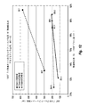
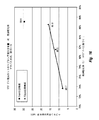
いくつかの実施形態では、改善された品質の減圧残油生成物は、沸騰床反応器を初期的に稼働する時と比べて、少なくとも10%、15%、20%、25%、30%、40%、50%、60%、または70%の粘度低下(例えば、300°Fでのブルックフィールド粘度によって測定)によって特徴付けることができる。 In some embodiments, the reduced quality decompression residual oil product is at least 10%, 15%, 20%, 25%, 30%, compared to when the boiling bed reactor is initially operational. It can be characterized by a 40%, 50%, 60%, or 70% viscosity reduction (eg, measured by Brookfield viscosity at 300 ° F.).
いくつかの実施形態では、改善された品質の減圧残油生成物は、沸騰床反応器を初期的に稼働する時と比べて、少なくとも5%、7.5%、10%、12.5%、15%、20%、25%、または30%のアスファルテン含有量の減少によって特徴付けることができる。 In some embodiments, the reduced quality decompression residual oil product is at least 5%, 7.5%, 10%, 12.5% compared to when the boiling bed reactor is initially operational. , 15%, 20%, 25%, or 30% can be characterized by a reduction in asphaltene content.
いくつかの実施形態では、改善された品質の減圧残油生成物は、沸騰床反応器を初期的に稼働する時と比べて、少なくとも2%、4%、6%、8%、10%、12.5%、15%、または20%の微小残留炭素含有量の減少(例えば、MCR含有量で測定)によって特徴付けることができる。 In some embodiments, the reduced quality decompression residual oil product is at least 2%, 4%, 6%, 8%, 10%, compared to when the boiling bed reactor is initially operational. It can be characterized by a 12.5%, 15%, or 20% reduction in microremaining carbon content (eg, measured by MCR content).
いくつかの実施形態では、改善された品質の減圧残油生成物は、沸騰床反応器を初期的に稼働する時と比べて、少なくとも5%、7.5%、10%、15%、20%、25%、30%、または35%の硫黄含有量の減少によって特徴付けることができる。 In some embodiments, the reduced quality decompression residual oil product is at least 5%, 7.5%, 10%, 15%, 20 compared to when the boiling bed reactor is initially operational. It can be characterized by a reduction in sulfur content of%, 25%, 30%, or 35%.
いくつかの実施形態では、改善された品質の減圧残油生成物は、密度の低下によって特徴付けることができ、これは、沸騰床反応器を初期的に稼働する時と比べて、少なくとも0.4、0.6、0.8、1.0、1.3、1.6、2.0、2.5または3.0の°API比重の増加として表すことができる。 In some embodiments, the reduced quality decompression residual oil product can be characterized by a decrease in density, which is at least 0.4 compared to when the boiling bed reactor is initially operational. , 0.6, 0.8, 1.0, 1.3, 1.6, 2.0, 2.5 or 3.0 ° API gravity increase.
いくつかの実施形態では、改善された品質の減圧残油生成物は、沸騰床反応器を初期的に稼働する時と比べて、少なくとも2%、4%、6%、8%、10%、12.5%、15%、または20%の沈降物含有量の減少によって特徴付けることができる。 In some embodiments, the reduced quality decompression residual oil product is at least 2%, 4%, 6%, 8%, 10%, compared to when the boiling bed reactor is initially operational. It can be characterized by a 12.5%, 15%, or 20% reduction in sediment content.
一般的に、減圧残油生成物は、燃料油、溶媒脱アスファルト化、コーキング、発電所燃料、および/または部分酸化(例えば、水素を発生させるためのガス化)に用いることができる。燃料油中に許容される汚染物質量に対する制限のため、本明細書に開示される二元触媒系水素化処理システムを用いて減圧残油生成物の品質を改善することは、減圧残油を規格内にするのに必要とされるより高価なカッターストックの量を減らし得る。それはまた、水素処理システム全体のより効率的な稼働のためにその他の場所でカッターストックが用いられるプロセス全体の負担も軽減する。 In general, decompressed residual oil products can be used for fuel oils, solvent deasphaltification, caulking, power plant fuels, and / or partial oxidation (eg, gasification to generate hydrogen). Due to the limitation on the amount of contaminants allowed in the fuel oil, improving the quality of the decompression residual oil product using the dual catalytic hydrotreated system disclosed herein can be used to reduce the decompression residue. It can reduce the amount of more expensive cutter stock required to stay within specifications. It also reduces the burden on the entire process where cutter stock is used elsewhere for more efficient operation of the entire hydrogen treatment system.
いくつかの実施形態において、分散金属硫化物触媒粒子は、1μm未満のサイズ、または約500nm未満のサイズ、または約250nm未満のサイズ、または約100nm未満のサイズ、約50nm未満のサイズ、または約25nm未満のサイズ、または約10nm未満のサイズ、または約5nm未満のサイズである。 In some embodiments, the dispersed metal sulfide catalyst particles are less than 1 μm in size, or less than about 500 nm, or less than about 250 nm, or less than about 100 nm, less than about 50 nm, or about 25 nm. Less than, or less than about 10 nm, or less than about 5 nm.
いくつかの実施形態において、分散金属硫化物触媒粒子は、触媒前駆体から重油内においてその場で形成される。例として、限定するものではないが、当該分散金属硫化物触媒粒子は、触媒前駆体の熱分解および活性金属硫化物触媒粒子の形成に先立ち触媒前駆体を重油全体へ混合することによって形成することができる。更なる例として、方法には、触媒前駆体を希釈剤炭化水素と混合して希釈された前駆体混合物を形成し、当該希釈された前駆体混合物を重油と混合して調整済み重油を形成し、そして、当該調整済み重油を加熱して触媒前駆体を分解し分散金属硫化物触媒粒子を重油内においてその場で形成することが含まれてよい。 In some embodiments, the dispersed metal sulfide catalyst particles are formed in situ from the catalyst precursor in heavy oil. By way of example, but not limited to, the dispersed metal sulfide catalyst particles are formed by mixing the catalyst precursor with the whole heavy oil prior to the thermal decomposition of the catalyst precursor and the formation of the active metal sulfide catalyst particles. Can be done. As a further example, the method involves mixing the catalytic precursor with a diluent hydrocarbon to form a diluted precursor mixture and mixing the diluted precursor mixture with heavy oil to form a conditioned heavy oil. , And the adjusted heavy oil may be heated to decompose the catalyst precursor to form dispersed metal sulfide catalyst particles in situ in the heavy oil.
本発明におけるこれら及びその他の利点並びに特徴は、以下の記載および添付の請求項からより十分に明らかとなり、または本明細書の記載の発明の実施によって理解されよう。 These and other advantages and features in the present invention will be more fully apparent from the following and accompanying claims, or will be understood by the practice of the invention described herein.
本発明における上記およびその他の利点並びに特徴をより明確にするために、添付の図に示すその特定の実施形態を参照して本発明のより具体的な説明を行う。これらの図面は発明の典型的な実施形態を表すものに過ぎず、したがってその範囲に限定するものではないことを理解されたい。本発明は、添付の図を用いてさらに具体的かつ詳細に記載され説明される。
I.序論と定義
本発明は、沸騰床水素処理システムにおいて二元触媒システムを用いて、重油から転化された炭化水素転化生成物および改善された品質の減圧残油生成物を生成する方法およびシステムに関する。この方法およびシステムは、固体担持(すなわち不均一な)触媒と、十分に分散した(すなわち均質な)触媒粒子とからなるを有する2元触媒システムを用いるものに関する。前記二元触媒システムは、通常ならば固体担持沸騰床触媒から成る単一の触媒を用いた沸騰床水素処理システムを改良するのに用いることができる。
I. Introduction and Definitions The present invention relates to methods and systems for producing hydrocarbon conversion products converted from heavy oil and reduced quality decompression residual oil products using a dual catalyst system in a boiling bed hydrogen treatment system. The methods and systems relate to those using a dual catalyst system consisting of a solid-supported (ie, non-uniform) catalyst and well-dispersed (ie, homogeneous) catalyst particles. The two-way catalyst system can be used to improve a boiling bed hydrogen treatment system using a single catalyst, which would normally consist of a solid-supported boiling bed catalyst.
例示として、改善された品質の残油生成物を含む重油の転化生成物を生成するように沸騰床水素処理システムを改良する方法は、(1)不均一触媒を用いて重油を水素処理し初期品質の減圧残油生成物を含む転化生成物を生成するように沸騰床反応器を稼動する工程と、(2)その後、分散金属硫化物触媒粒子と不均一触媒とからなるを有する2元触媒システムを用いて稼動するように沸騰床反応器を改良する工程と、(3)前記沸騰床反応器を初期的に稼働する時よりも改善された品質の減圧残油生成物を含む転化生成物を生成するように前記改良された沸騰床反応器を稼働する工程とを有する。 By way of example, methods of improving a boiling bed hydrogen treatment system to produce heavy oil conversion products containing improved quality residual oil products are as follows: (1) Hydrogenate heavy oil with a heterogeneous catalyst and initially A binary catalyst comprising a step of operating a boiling bed reactor to produce a conversion product containing a quality decompressed residual oil product, followed by (2) dispersed metal sulfide catalyst particles and a heterogeneous catalyst. A step of improving the boiling bed reactor to operate with the system and (3) a conversion product containing reduced pressure residual oil product of improved quality than when the boiling bed reactor was initially operated. It has a step of operating the improved boiling bed reactor to produce.
「重油原料」という用語は、重質原油、油砂瀝青、精製処理で残ったバレル底部および残留物(例えばビスブレーカ底部物)、並びに、多量の高沸騰炭化水素留分を含有し、および/または、不均一触媒を不活性化および/もしくはコークス前駆体および沈降物の形成を生じ若しくはもたらす多量のアスファルテンを含むその他の任意の低品質材料を指す。重油原料の例としては、これらに限られないが、ロイドミンスター重油、コールド湖瀝青、アサバスカ瀝青、常圧塔底、減圧塔底、残留物(または「残油」("resid"))、残油ピッチ、溶媒脱アスファルト化で得られた減圧残油(例えば、ウラルVR、アラブミディウムVR、アサバスカVR、コールド湖VR、マヤVR、チチミンVRなど)、脱アスファルト化の副産物として得られるアスファルト液体、並びに、原油、タール砂由来の瀝青、液化石炭、シェール油、又は、蒸留し高温分離し溶媒抽出等をするコールタール原料などを扱った後に残る不揮発液体留分が挙げられる。更なる例として、常圧塔底は少なくとも343℃(650°F)の公称沸点を有し得るが、カットポイントは製油所間で異なり380℃(716°F)の高さに達する場合もあることが理解されている。減圧塔底は少なくとも524℃(975°F)の公称沸点を有し得るが、カットポイントは製油所間で異なり538℃(1000°F)または565℃(1050°F)の高さに達する場合もあることが理解されている。 The term "heavy oil raw material" contains heavy crude oil, oil sands bitumen, barrel bottoms and residues left over from refining (eg, visbreaker bottoms), and large amounts of high boiling hydrocarbon fractions, and / Alternatively, it refers to any other low quality material containing large amounts of asphaltene that inactivates heterogeneous catalysts and / or produces or results in the formation of coke precursors and precipitates. Examples of heavy oil raw materials are, but are not limited to, Lloydminster heavy oil, cold lake bitumen, asphalt bitumen, atmospheric pressure tower bottom, decompression tower bottom, residue (or "resid"), residue. Oil pitch, decompressed residual oil obtained by solvent deasphaltization (eg, Ural VR, Arabmidium VR, Asabaska VR, Cold Lake VR, Maya VR, Titimin VR, etc.), asphalt liquid obtained as a by-product of deasphaltization. , And the non-volatile liquid distillate remaining after handling crude oil, bitumen derived from tar sand, liquefied coal, shale oil, or coal tar raw material which is distilled and separated at a high temperature to extract a solvent. As a further example, the bottom of the atmospheric pressure column can have a nominal boiling point of at least 343 ° C (650 ° F), but the cut points vary between refineries and can reach heights of 380 ° C (716 ° F). Is understood. The bottom of the decompression column can have a nominal boiling point of at least 524 ° C (975 ° F), but the cut points vary between refineries and reach heights of 538 ° C (1000 ° F) or 565 ° C (1050 ° F). It is understood that there is also.
「アスファルテン」という用語は、重油原料中の材料を指し、典型的には、例えばプロパン、ブタン、ペンタン、ヘキサン、およびヘプタンなどのパラフィン系溶媒に不溶なものである。アスファルテンは、硫黄、窒素、酸素、及び金属などのヘテロ原子によって結び付けられた縮合環化合物の層を含み得る。アスファルテンは、80〜1200個の炭素原子を有する広範囲の複雑な化合物を広く含むことができ、溶媒技術によって決定されるように1200〜16900の範囲の分子量を占める。原油中の約80〜90%の金属はより高濃度の非金属ヘテロ原子と共にアスファルテン留分に含まれ、それにより原油中のその他の炭化水素よりもアスファルテン分子の親水性が高く疎水性が低くなる。図1に、A.G. BridgeおよびChevronの同僚等によって明らかにされたアスファルテン分子の仮説的構造を示す。一般的に、アスファルテンは不溶性物質法の結果に基づいて典型的には定義されるが、アスファルテンについての1以上の定義を用いることができる。具体的には、一般的に用いられているアスファルテンの定義は、ヘプタン不溶性物質からトルエン不溶性物質を引いたものである(すなわち、アスファルテンはトルエン中で可溶であり、トルエン中で不溶な沈降物および残留物はアスファルテンとして計算されない)。このような様式で定義されたアスファルテンは、"C7アスファルテン"として参照し得る。しかしながら、同等の信頼性を有する代替の定義として、ヘプタン不溶性物質からトルエン不溶性物質を引いたものが測定され"C5アスファルテン"として一般的に参照されるものが用いられてもよい。本発明の例では、C7アスファルテンの定義が用いられているが、C5アスファルテンの定義も容易に代用することができる。 The term "asphaltene" refers to a material in a heavy oil source and is typically insoluble in paraffinic solvents such as propane, butane, pentane, hexane, and heptane. Asphaltene can include layers of fused ring compounds linked by heteroatoms such as sulfur, nitrogen, oxygen, and metals. Asphaltene can broadly contain a wide range of complex compounds with 80-1200 carbon atoms and occupy a molecular weight in the range 1200-16900 as determined by solvent technology. About 80-90% of the metal in crude oil is contained in the asphaltene fraction with higher concentrations of non-metal heteroatoms, which makes the asphaltene molecules more hydrophilic and less hydrophobic than other hydrocarbons in crude oil. .. In FIG. 1, A. G. The hypothetical structure of the asphaltene molecule revealed by colleagues of Bridge and Chevron is shown. In general, asphaltene is typically defined based on the results of the insoluble matter method, but one or more definitions for asphaltene can be used. Specifically, the commonly used definition of asphaltene is heptane-insoluble material minus toluene-insoluble material (ie, asphaltene is soluble in toluene and insoluble in toluene. And residues are not calculated as asphaltene). Asphaltene defined in this manner may be referred to as "C 7 asphaltenes". However, as the definition of alternative with comparable reliability, it is measured minus the toluene insoluble material from heptane insolubles "C 5 asphaltenes" as may be is used what is commonly referred to. In the example of the present invention, but C 7 asphaltenes definitions are used, it can be easily substituted definition of C 5 asphaltenes.
"水素化分解"および"水素転換"という用語は、重油原料の沸点範囲を低下させることを主目的とする処理であって、その原料の大部分が元の原料の沸点範囲よりも低い沸点範囲の生成物に転化される処理を示す。水素化分解または水素転化は一般的に、大きな炭化水素分子を、より少ない数の炭素原子およびより高い水素/炭素比を有する小さな分子断片へと分裂させることに関する。水素化分解が生じるメカニズムは典型的には、熱断片化中における炭化水素遊離基の形成を含み、水素による遊離基端または部分のキャッピングを伴う。水素原子又は水素基は水素化分解中に炭化水素遊離基と反応するが、これは活性触媒部位で、又は活性触媒部位によって生じ得る。 The terms "hydrogenation decomposition" and "hydrogen conversion" are treatments whose main purpose is to lower the boiling point range of heavy oil raw materials, and most of the raw materials have a boiling point range lower than the boiling point range of the original raw material. The process of conversion to the product of is shown. Hydrocracking or hydroconversion generally relates to splitting large hydrocarbon molecules into smaller molecular fragments with a smaller number of carbon atoms and a higher hydrogen / carbon ratio. The mechanism by which hydrocracking occurs typically involves the formation of hydrocarbon free radicals during thermal fragmentation, with capping of free radical ends or moieties by hydrogen. A hydrogen atom or hydrogen group reacts with a free hydrocarbon moiety during hydrocracking, which can occur at the active catalyst site or by the active catalyst site.
「水素化精製(hydrotreating)」という用語は、硫黄、窒素、酸素、ハロゲン化合物、微量金属などの不純物を原料から取り除き、オルフィンを飽和させ、および/または、それら自体を反応させるよりもそれらを水素と反応させることにより炭化水素遊離基を安定させることを主目的とする操作を指す。当該主目的は、原料の沸点範囲を変えるものではない。水素化精製は多くの場合、固定床反応器を用いて行われるが、その他の水素処理反応器が水素化精製に用いられてもよく、例えば沸騰床水素化精製器が挙げられる。 The term "hydrotreating" removes impurities such as sulfur, nitrogen, oxygen, halogen compounds, trace metals from raw materials, saturates olphins, and / or hydrogenates them rather than reacting them themselves. Refers to an operation whose main purpose is to stabilize a hydrocarbon free radical by reacting with. The main purpose is not to change the boiling point range of the raw material. Hydrodesulfurization is often performed using a fixed bed reactor, but other hydrogen treatment reactors may be used for hydrorefining, such as boiling bed hydrorefiners.
当然、「水素化分解」または「水素転化」も、原料からの硫黄および窒素の除去、およびオルフィン飽和、並びに水素化精製に一般的に付随するその他の反応に関与しうる。「水素処理(hydroprocessing)」および「水素転化」は、広く「水素化分解」および「水素化精製(hydrotreating)」プロセスの双方を指し、スペクトルの対向端および当該スペクトルに沿うその間のすべてのものを定義する。 Of course, "hydrodecomposition" or "hydroconversion" can also be involved in the removal of sulfur and nitrogen from the feedstock, and olphin saturation, as well as other reactions commonly associated with hydrorefining. "Hydroxidation" and "hydrodesulfurization" broadly refer to both "hydrocracking" and "hydrotreating" processes, including the opposite ends of the spectrum and everything in between along the spectrum. Define.
「水素化分解反応器」という用語は、その中において、水素および水素化分解触媒の存在下で原料を水素化分解する(すなわち、沸点範囲を低下させる)ことを主目的とする任意の容器を指す。水素化分解反応器は、重油原料および水素が導入される注入ポートおよび改良された原料または材料が抜き取られる排出ポートと、大きな炭化水素分子からより小さな分子への断片化を生じさせるために炭化水素遊離基を形成する十分な熱エネルギーとを有することを特徴とする。水素化分解反応器の例としては、これに限られないが、スラリー相反応器(すなわち、気体―液体の2相系)、沸騰床反応器(すなわち、気体―液体―固体の3相系)、固定床反応器(すなわち、典型的には、重油へ同時に、ただし可能性としては向流的に流れる水素により、固体不均一触媒の固定床を下方に浸透するまたは上方に流れる液体供給を含む3相系)が挙げられる。 The term "hydrogenation reactor" refers to any container in it whose primary purpose is to hydrolyze (ie, lower the boiling range) the raw material in the presence of hydrogen and a hydrocracking catalyst. Point to. Hydrocarbon decomposition reactors have an injection port into which heavy oil raw materials and hydrogen are introduced and an discharge port from which improved raw materials or materials are extracted, and hydrocarbons to produce fragmentation from large hydrocarbon molecules to smaller molecules. It is characterized by having sufficient thermal energy to form free groups. Examples of hydrocracking reactors are, but are not limited to, slurry phase reactors (ie, gas-liquid two-phase systems), boiling bed reactors (ie, gas-liquid-solid three-phase systems). Includes a liquid supply that penetrates the fixed bed of the solid heterogeneous catalyst downwards or flows upwards, typically with a fixed bed reactor (ie, typically with hydrogen flowing simultaneously, but potentially countercurrently, into heavy oil. Three-phase system) can be mentioned.
「水素化分解温度」という用語は、重油原料の十分な水素化分解を引き起こすのに必要な最低温度を指す。一般に、水素化分解温度は、好ましくは約399℃(750°F)〜約460℃(860°F)の範囲内に、より好ましくは約418℃(785°F)〜約443℃(830°F)の範囲に、もっとも好ましくは約421℃(790°F)〜約440℃(825°F)の範囲に収まることとなる。 The term "hydrocracking temperature" refers to the minimum temperature required to cause sufficient hydrocracking of heavy oil feedstock. In general, the hydrocracking temperature is preferably in the range of about 399 ° C (750 ° F) to about 460 ° C (860 ° F), more preferably from about 418 ° C (785 ° F) to about 443 ° C (830 °). It will be in the range of F), most preferably in the range of about 421 ° C (790 ° F) to about 440 ° C (825 ° F).
「気体―液体スラリー相水素化分解反応器」という用語は、連続した液相と、当該液相内に気泡の「スラリー」を形成する気体分散相とを含む水素処理反応器を指す。前記液相は典型的には、低濃度の分散金属硫化物触媒を含む炭化水素原料を有し、気相は典型的には、水素ガス、硫化水素、および気化した低沸点炭化水素生成物を有する。前記液相は任意選択的に水素供与体溶媒を含むことができる。「気体―液体―固体三相スラリー水素化分解反応器」という用語は、固体触媒が液体および気体と共に使用される場合に用いられる。前記気体には、水素、硫化水素、および気化した低沸点炭化水素生成物が含まれ得る。「スラリー相反応器」とは、広く両方の種類の反応器(例えば、分散金属硫化物触媒粒子を伴うもの、ミクロンサイズ又はそれより大きい微粒子触媒を伴うもの、および両方を含むもの)を指す。 The term "gas-liquid slurry phase hydrocracking reactor" refers to a hydrogen treatment reactor comprising a continuous liquid phase and a gas dispersion phase that forms a "slurry" of bubbles within the liquid phase. The liquid phase typically has a hydrocarbon feedstock containing a low concentration of dispersed metal sulfide catalyst, and the gas phase typically contains hydrogen gas, hydrogen sulfide, and vaporized low boiling point hydrocarbon products. Have. The liquid phase can optionally contain a hydrogen donor solvent. The term "gas-liquid-solid three-phase slurry hydrocracking reactor" is used when solid catalysts are used with liquids and gases. The gas may include hydrogen, hydrogen sulfide, and vaporized low boiling hydrocarbon products. "Slurry phase reactor" broadly refers to both types of reactors (eg, those with dispersed metal sulfide catalyst particles, those with micron-sized or larger fine particle catalysts, and those containing both).
「固体不均一触媒」、「不均一触媒」、および「担持触媒」という用語は、沸騰床および固定床水素処理システムにおいて典型的に使用される触媒をいい、主に、水素化分解、水素転化、水素化脱金属、および/または水素化精製のために設計された触媒が含まれる。不均一触媒は典型的には、(i)表面積が大きく相互接続された流路又は孔を有する触媒担体と、(ii)前記流路または孔内に分散するコバルト、ニッケル、タングステン、およびモリブデンの硫化物のような微細な活性触媒粒子とを有する。前記担体の孔は典型的には、前記不均一触媒の機構的健全性を維持し、また前記反応器において分解され過度に微細なものが形成されるのを防止するため、大きさが限定される。不均一触媒は、円筒形状のペレット、円筒形状の押出物、例えば三葉状、リング状、鞍状などのその他の形状、または球状の固体として生産することができる。 The terms "solid heterogeneous catalyst", "heterogeneous catalyst", and "supported catalyst" refer to catalysts typically used in boiling and fixed bed hydrogenation systems, primarily hydrocracking, hydroconversion. , Hydrodesulfurization, and / or catalysts designed for hydrogenation purification. Heterogeneous catalysts typically consist of (i) a catalyst carrier with large surface area interconnected channels or pores and (ii) cobalt, nickel, tungsten, and molybdenum dispersed in the channels or pores. It has fine active catalyst particles such as sulfide. The pores of the carrier are typically limited in size in order to maintain the mechanical integrity of the heterogeneous catalyst and to prevent decomposition in the reactor to form excessively fine material. To. Heterogeneous catalysts can be produced as cylindrical pellets, cylindrical extrudes, other shapes such as trifoliate, ring-shaped, saddle-shaped, or spherical solids.
「分散金属硫化物触媒粒子(dispersed metal sulfide catalyst particles)」および「分散触媒」という用語は、1μm未満、例えば約500nm未満の直径、または約250nm未満の直径、または100nm未満の直径、または約50nm未満の直径、または約25nm未満の直径、または約10nm未満の直径、または約5nm未満の直径の粒子サイズを有する触媒粒子を指す。「分散金属硫化物触媒粒子」という用語には、分子触媒化合物または分子分散触媒化合物が含まれてもよい。前記"分散金属硫化物触媒粒子"という用語は、1μmより大きな金属硫化物粒子および金属硫化物粒子凝集体を除く。 The terms "dispersed metallic sulfide catalyst particles" and "dispersion catalyst" are used in terms of less than 1 μm, such as diameters less than 1 μm, or diameters less than about 250 nm, or diameters less than 100 nm, or about 50 nm. Refers to catalytic particles with a particle size of less than, or less than about 25 nm, or less than about 10 nm, or less than about 5 nm. The term "dispersed metal sulfide catalyst particles" may include molecular catalyst compounds or molecular dispersion catalytic compounds. The term "dispersed metal sulfide catalyst particles" excludes metal sulfide particles larger than 1 μm and metal sulfide particle aggregates.
「分子分散触媒」という用語は、炭化水素原料または適切な希釈剤中でその他の触媒化合物若しくは分子から基本的に「溶解」または解離させられる触媒化合物を指す。それには、少数の触媒分子(例えば15個以下の分子)が互いに結合したものを含む非常に小さな触媒粒子が含まれてよい。 The term "molecular dispersion catalyst" refers to a catalytic compound that is essentially "dissolved" or dissociated from other catalytic compounds or molecules in a hydrocarbon feedstock or suitable diluent. It may include very small catalyst particles, including those in which a small number of catalyst molecules (eg, 15 or less molecules) are attached to each other.
「残留触媒粒子」という用語は、1つの容器から他の容器へ(例えば水素処理反応器から分離器および/またはその他の水素処理反応器へ)移す時に改良された材料と共に残る触媒粒子を指す。 The term "residual catalyst particles" refers to catalyst particles that remain with the improved material upon transfer from one container to another (eg, from a hydrogen treatment reactor to a separator and / or other hydrogen treatment reactor).
「調整済み原料」という用語は触媒前駆体が併合され十分に混合された炭化水素原料をいい、それにより、触媒前駆体の分解および活性触媒の形成時に、前記原料中においてその場で形成された分散金属硫化物触媒粒子を触媒が有することとなる。 The term "adjusted feedstock" refers to a hydrocarbon feedstock in which the catalyst precursor has been annexed and well mixed, thereby forming in situ in the feedstock during the decomposition of the catalyst precursor and the formation of the active catalyst. The catalyst will have dispersed metal sulfide catalyst particles.
「改良する」、「改良している」、「改良された」という用語は、水素処理の対象になっている若しくは対象となる原料、または結果物または生成物を説明するために用いられている場合、原料の分子量の減少、原料の沸点範囲の減少、原料の比重の減少、アスファルテンの濃度の低下、炭化水素遊離基の濃度の低下、および/または、例えば硫黄、窒素、酸素、ハロゲンおよび/または金属などの不純物の量の減少のうちの1若しくはそれ以上を指す。 The terms "improved," "improved," and "improved" are used to describe a radical, product, or product that is or is subject to hydrogen treatment. If, the molecular weight of the raw material is reduced, the boiling range of the raw material is reduced, the specific gravity of the raw material is reduced, the concentration of asphaltene is reduced, the concentration of free radicals of hydrocarbons is reduced, and / or, for example, sulfur, nitrogen, oxygen, halogen and / Or, it refers to one or more of the reductions in the amount of impurities such as metals.
「酷度(severity)」という用語は、水素処理中に重油に投入されるエネルギー量をいい、多くの場合、温度暴露期間と共に水素処理反応器の稼働温度に関係する(すなわち、温度が高いほど酷度が高いことと関連し、温度が低いほど酷度が低いことと関連する)。酷度が高いと一般的に水素処理反応器によって生成される転化生成物の量が増加するが、当該転化生成物には望ましい生成物と望ましくない転化製生物との両方が含まれる。望ましい転化生成物としては、分子量、沸点、および比重が低下した炭化水素が挙げられ、それには、ナフサ、ディーゼル、ジェット燃料、灯油、ワックス、燃料油などの最終生成物が含まれ得る。その他の望ましい転化生成物としては、従来式の精製および/または蒸留プロセスを用いてさらに処理することができるより高沸点の炭化水素が挙げられる。望ましくない転化生成物としては、コークス、沈降物、金属、並びに、水素処理装置、例えば反応器の内部構成要素、分離器、フィルタ、パイプ、塔、熱交換器および不均一触媒などに堆積して汚損を引き起こす可能性のあるその他の固体材料が挙げられる。望ましくない転化生成物は、また、蒸留後に残る未転化の残油、例えば常圧塔底(「ATB」)または減圧塔底(「VTB」)を指すこともできる。望ましくない転化生成物を最小限に抑えることにより、装置の汚染、および装置の清掃に必要な停止が低減される。しかしながら、下流分離装置を適切に機能させ、および/または、コークス、沈降物、金属、および、装置に堆積して汚染する可能性があるが当該残りの残油により輸送可能なその他の固体物質を収容する液体輸送媒体を提供するため、未転化の残油が所望な量あってもよい。 The term "severity" refers to the amount of energy put into heavy oil during hydrogen treatment, often related to the operating temperature of the hydrogen treatment reactor along with the temperature exposure period (ie, the higher the temperature). It is associated with higher severity, and lower temperatures are associated with lower severity). Higher severity generally increases the amount of conversion products produced by the hydrogen treatment reactor, which includes both desirable and undesired conversion organisms. Desirable conversion products include hydrocarbons with reduced molecular weight, boiling point, and specific gravity, which may include final products such as naphtha, diesel, jet fuel, kerosene, waxes, fuel oils and the like. Other desirable conversion products include higher boiling hydrocarbons that can be further treated using conventional purification and / or distillation processes. Unwanted conversion products include coke, sediment, metals, and deposits on hydrogen treatment equipment such as reactor internal components, separators, filters, pipes, towers, heat exchangers and heterogeneous catalysts. Other solid materials that can cause fouling include. The undesired conversion product can also refer to unconverted residual oil remaining after distillation, such as atmospheric pressure column bottom (“ATB”) or decompression column bottom (“VTB”). Minimizing unwanted conversion products reduces equipment contamination and outages required for equipment cleaning. However, the downstream separator may function properly and / or coke, sediment, metal, and other solids that may deposit and contaminate the device but can be transported by the remaining residual oil. There may be a desired amount of unconverted residual oil to provide a liquid transport medium to contain.
未転化の残油はまた、有用な生成物、例えば燃料油および道路建設用のアスファルト等であってもよい。残油が燃料油に用いられる場合、燃料の品質は、粘度、比重、アスファルテン含有量、炭素含有量、硫黄含有量、および沈降物等の1若しくはそれ以上の特性によって測定することができ、それぞれの値が低いものほど一般的により品質の高い燃料油に対応する。例えば、燃料油用に設計される減圧残油は、粘度が低い場合ほど(例えば、流動して取り扱われるためにカッターストック(例えば、減圧軽油またはサイクルオイル)の必要性が少なくなることから)より品質が高くなる。同様に、減圧残油における硫黄含有量の減少により、最大硫黄含有量の規格を満たすより高価なカッターストックを用いた希釈剤の必要性が少なくなる。アスファルテン、沈降物、および/または炭素含有量の減少は、燃料油の安定性を改善することができる。 The unconverted residual oil may also be useful products such as fuel oil and asphalt for road construction. When residual oil is used in fuel oil, fuel quality can be measured by one or more properties such as viscosity, specific gravity, asphaltene content, carbon content, sulfur content, and precipitates, respectively. The lower the value of, the higher the quality of fuel oil in general. For example, decompressed residual oils designed for fuel oils are of lower quality (eg, because they require less cutter stock (eg, decompressed gas oil or cycle oil) to be handled in a fluid manner) as they have lower viscosities. Will be higher. Similarly, the reduction in sulfur content in decompressed residual oil reduces the need for diluents with more expensive cutter stocks that meet the maximum sulfur content specification. Decreased asphaltene, sediment, and / or carbon content can improve the stability of the fuel oil.
温度に加えて、「酷度」は、「転化」および「スループット」の一方または両方に関連し得る。酷度の上昇が、転化の増加および/またはスループットの増大若しくは低下を引き起こすかどうかは、重油原料の品質および/または水素処理システム全体の物質収支に依存する。例えば、より多くの量の供給材料を変換し、および/またはより多くの量の材料を下流装置に供給することが望まれる場合、酷度の上昇は、必ずしも留分転化率を増加させることなく主にスループットの増大を引き起し得る。これには残油留分(ATBおよび/またはVTB)が燃料油として販売される場合が含まれ、スループットを増大させずに転化率を増大させると、この生成物の量が減る可能性がある。残油留分に対する改良された材料の割合の増加が望まれる場合、スループットを必ずしも増大させることなく転化率を主に増加させることが望ましいことがある。水素処理反応器に導入される重油の品質が変動する場合、残油留分に対する改良された材料の割合、および/または生成される最終生成物の所望の絶対量を維持するため、転化率およびスループットのいずれか一方または両方を選択的に増加または低下させることが望ましい。 In addition to temperature, "severity" can be related to one or both of "conversion" and "throughput". Whether an increase in severity causes an increase in conversion and / or an increase or decrease in throughput depends on the quality of the heavy oil feedstock and / or the mass balance of the entire hydrogen treatment system. For example, if it is desired to convert a larger amount of feed material and / or feed a larger quantity of material to the downstream equipment, the increased severity does not necessarily increase the fraction conversion rate. It can mainly cause an increase in throughput. This includes cases where the residual oil fraction (ATB and / or VTB) is sold as fuel oil, and increasing the conversion rate without increasing throughput can reduce the amount of this product. .. If an increase in the ratio of the improved material to the residual oil fraction is desired, it may be desirable to primarily increase the conversion rate without necessarily increasing the throughput. If the quality of heavy oil introduced into the hydrogen treatment reactor fluctuates, the conversion rate and / or conversion rate and / or conversion rate to maintain the desired absolute amount of final product produced, and / or the ratio of the improved material to the residual oil fraction. It is desirable to selectively increase or decrease either or both of the throughput.
「転化率」および「留分転化率」という用語は、百分率で表されることが多く、低沸点および/または低分子量物質に有利に転化される重油の割合を指す。転化率は、定義されたカット点よりも低い沸点で生成物に転化された初期の残油含有量(すなわち、定義された残油カット点よりも高い沸点を有する成分)のパーセンテージとして表される。残油カットポイントの定義は様々であり、通常524℃(975°F)、538℃(1000°F)、565℃(1050°F)などを含むことができる。これは、定義されたカット点よりも高い沸点を有する成分の濃度を決定するために、供給物流若しくは生成物流の蒸留分析により測定することができる。留分転化率は、(F−P)/Fとして表される。ここで、Fは併合された供給物流中の残油量であり、Pは併合された生成物流中の残油量である。供給物および生成物の残油含有量はともに同じカットポイントの定義に基づいている。残油量は、多くの場合、定義されたカット点よりも高い沸点を有する成分の質量に基づいて定義されるが、体積またはモルでの定義もまた用いられてよい。 The terms "conversion rate" and "fraction conversion rate" are often expressed as percentages and refer to the percentage of heavy oil that is converted in favor of low boiling points and / or low molecular weight materials. Conversion is expressed as a percentage of the initial residual oil content (ie, components with a boiling point higher than the defined residual oil cut point) converted to the product at a boiling point lower than the defined cut point. .. The definition of the residual oil cut point varies and can usually include 524 ° C (975 ° F), 538 ° C (1000 ° F), 565 ° C (1050 ° F) and the like. This can be measured by distillation analysis of the feed or product stream to determine the concentration of components having a boiling point higher than the defined cut point. The fraction conversion rate is expressed as (FP) / F. Here, F is the amount of residual oil in the merged supply distribution, and P is the amount of residual oil in the merged production distribution. The residual oil content of the feed and product is both based on the same cutpoint definition. The amount of residual oil is often defined based on the mass of the component having a boiling point higher than the defined cut point, but the definition in volume or molar may also be used.
「スループット」という用語は、時間の関数として水素処理反応器に導入される供給材料の量を指す。これはまた、水素処理反応器から除去される転化生成物の総量に関係し、当該総量には望ましい生成物と望ましくない生成物の合わせた量が含まれる。スループットは、1日あたりのバレルなどの容積基準で、または時間当たりのメトリックトンなどの質量基準で表すことができる。一般的な使用法では、スループットは、重油原料自体(例えば、減圧塔底部など)のみの質量若しくは容積供給速度として定義される。この定義は通常、希釈剤、または水素転化ユニットへの供給物全体に含まれることがあるその他の成分の量を含まないが、それら他の成分を含む定義が用いられてもよい。 The term "throughput" refers to the amount of feedstock introduced into a hydrogen treatment reactor as a function of time. It also relates to the total amount of conversion products removed from the hydrogen treatment reactor, which includes the combined amount of desirable and undesired products. Throughput can be expressed on a volume basis, such as barrels per day, or on a mass basis, such as metric tons per hour. In general usage, throughput is defined as the mass or volume feed rate of the fuel oil feedstock itself (eg, the bottom of the decompression tower) alone. This definition usually does not include the amount of diluent or other component that may be included in the entire feed to the hydrogen conversion unit, but definitions that include those other components may be used.
「沈降物」という用語は、液体流中で形成され沈殿し得る固体を指す。沈降物としては、転化後に沈殿する無機物、コークス、または不溶性アスファルテンが挙げられる。石油生成物中の沈降物は、ISO 10307およびASTM D4870の一部として公開されている残留燃料油における全沈降物のためのIP−375熱濾過試験手順を用いて測定される。その他の試験には、IP−390沈殿試験およびシェール熱濾過試験が含まれる。沈降物は、処理および取り扱い中に固体を形成する性質を有するオイル成分に関係する。これらの固体形成成分は、水素転化処理において複数の望ましくない影響を及すが、当該影響には生成物の品質劣化や機器の汚染に関する稼働性上の問題が含まれる。沈降物の厳密な定義は沈降物試験における固形物の測定に基づいているが、この用語は、実際の固形物としては油中に存在しないがある条件下では固体形成に寄与する油自体の固体形成成分を指すものとして広義に用いられるのが一般的である点に留意すべきである。 The term "precipitate" refers to a solid that can form and settle in a liquid stream. Precipitates include inorganics, cokes, or insoluble asphaltene that precipitate after conversion. Sediments in petroleum products are measured using the IP-375 thermal filtration test procedure for total sediments in residual fuel oils published as part of ISO 10307 and ASTM D4870. Other tests include IP-390 precipitation test and shale heat filtration test. Sediments relate to oil components that have the property of forming solids during treatment and handling. These solid-forming components have multiple undesired effects on the hydrogen conversion process, including operational problems with product quality degradation and equipment contamination. Although the strict definition of sediment is based on the measurement of solids in sediment tests, the term is the solid of the oil itself that contributes to solid formation under certain conditions that are not present in the oil as actual solids. It should be noted that it is generally used in a broad sense to refer to the forming component.
「汚染」という用語は、処理を妨害する望ましくない相(汚染物質)の形成を指す。汚染物質は、通常、処理装置内に沈殿し集まる炭素質物質または固体である。装置の汚染は、装置の停止、装置の性能の低下、熱交換器または加熱器における汚れの付着による断熱効果に起因したエネルギー損失の増加、装置清掃のためのメンテナンス費用の増加、精留塔の効率の低下、および不均一触媒の反応度の低下の結果、生成物の損失をもたらす。 The term "contamination" refers to the formation of unwanted phases (pollutants) that interfere with treatment. The contaminants are usually carbonaceous substances or solids that settle and collect in the treatment equipment. Equipment contamination can result in equipment outages, equipment performance degradation, increased energy loss due to the thermal insulation effect of dirt on heat exchangers or heaters, increased maintenance costs for equipment cleaning, and rectification towers. As a result of reduced efficiency and reduced reactivity of the heterogeneous catalyst, product loss occurs.
II.沸騰床水素処理反応器およびシステム
図2A〜2Dは、重油などの炭化水素原料を水素処理するのに用いられる沸騰床水素処理反応器およびシステムの非限定的な例を概略的に示したものであり、当該反応器およびシステムは本発明において二元触媒を用いるように改良され得る。この例示的な沸騰床水素処理反応器およびシステムは、段間分離、一体化された水素化精製および/または一体化された水素化分解を含むことができることを理解されよう。
II. Boiling Bed Hydrogen Treatment Reactors and Systems Figures 2A-2D outline non-limiting examples of boiling bed hydrogen treatment reactors and systems used to hydrogenate hydrocarbon raw materials such as heavy oil. Yes, the reactor and system can be modified to use dual catalysts in the present invention. It will be appreciated that this exemplary boiling bed hydrogenation reactor and system can include interstage separation, integrated hydropurification and / or integrated hydrocracking.
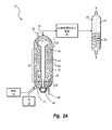
図2Aは、C−E Lummusによって開発されたLC精製水素化分解システムで用いられる沸騰床水素処理反応器10を概略的に示す。沸騰床反応器10は、底部近くに原料14および加圧された水素ガス16が導入される注入ポート12と、頂部に水素処理された材料20が抜き取られる排出ポート18とを含む。
FIG. 2A schematically shows a boiling bed
反応器10は不均一触媒24を有する膨張触媒領域22をさらに含み、不均一触媒24は、沸騰床反応器10における液体炭化水素および気体(気泡25として概略的に示される)の上方移動によって重力に抗して膨張した状態または流動した状態で維持される。膨張触媒領域22の下端は分配器グリッドプレート26によって画定され、分配器グリッドプレート26は、沸騰床反応器10の底部と分配器グリッドプレート26との間に位置する下部不均一触媒不含領域28から膨張触媒領域22を分離する。分配器グリッドプレート26は、水素ガスおよび炭化水素を前記反応器にわたって均等に分配するように構成され、不均一触媒24が重力によって下部不均一系触媒不含領域28に落下するのを防止する。膨張触媒領域22の上端は、重力による前記下方向の力が、沸騰床反応器10において上方移動する原料及び気体の上昇力と同等若しくはそれを超過し始める高さにあり、不均一触媒24の膨張または分離が所与のレベルに達するようなっている。膨張触媒領域22の上は、上部不均一触媒不含領域30である。
The
沸騰床反応器10内の炭化水素およびその他の物質は、沸騰床反応器10の中央に位置し沸騰ポンプ34と当該沸騰床反応器10の底部で接続された再循環流路32によって、上部不均一触媒不含領域30から下部不均一触媒不含領域28へ連続的に再循環される。再循環流路32の頂部は漏斗形状の再循環カップ36が設けられてなり、当該再循環カップ36を通じて上部不均一触媒不含領域30から原料を引き込む。再循環流路32を通って下方に取り込まれた材料は、分配器グリッドプレート26を通って上方に進み、膨張触媒領域22に入るものであり、そこにおいて、注入ポート12を介して沸騰床反応器10に入り添加された新鮮な原料14および水素ガス16と混合される。沸騰床反応器10を通って上方へ進む混合された材料を連続的に循環させることは、不均一触媒24を膨張触媒領域22内で膨張状態若しくは流動状態に保ち、チャネリングを最小にし、反応速度を制御し、また、発熱水素化反応によって放出される熱を安全なレベルに保つのに役立つ。
The hydrocarbons and other substances in the boiling
新鮮な不均一触媒24は、沸騰床反応器10の頂部を貫通し膨張触媒領域22へ直接通じる触媒注入管38を介して、沸騰床反応器10内、例えば膨張触媒領域22内に導入される。使用された不均一触媒は、膨張触媒領域22の下端部から分配器グリッドプレート26および沸騰床反応器10の底部を貫通する触媒抜取管40を介して、膨張触媒領域22から抜き取られる。触媒抜取管40は、十分に使用された触媒と、部分的に使用されたが活性のある触媒と、新しく添加された触媒とを区別することができないため、ランダムに分布した不均一触媒24が典型的には「使用済み」触媒として沸騰床反応器10から抜き取られることを理解されよう。
The fresh
沸騰床反応器10から抜き取られた改良後の材料20は、分離器42(例えば、高温分離器、段間圧力差分離器、または常圧若塔しくは減圧塔などの蒸留塔)に導入されてよい。分離器42は、不揮発性留分48から1若しくはそれ以上の揮発性留分46を分離する。
The
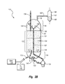
図2Bは、Hydrocarbon Research Incorporatedによって開発され、現在Axensによってライセンスされている水素―オイル水素化分解システムで用いられる沸騰床反応器110を概略的に示す。沸騰床反応器110は、重油原料114および加圧水素ガス116が導入される注入ポート112と、改良後の材料120が抜き取られる排出ポート118とを含む。不均一触媒124を有する膨張触媒領域122は、反応器110の底部と分配器グリッドプレート126間の下部触媒不含領域128から膨張触媒領域122を分離する分配器グリッドプレート126と、膨張触媒領域122と上部触媒不含領域130間の近似境界を画定する上端部129とによって拘束されている。点線の境界線131は、不均一触媒124の膨張状態または流動状態ではないときの近似レベルを概略的に示す。
FIG. 2B schematically shows a boiling
材料は、沸騰ポンプ134に接続された再循環流路132によって反応器110内で連続的に再循環される。当該沸騰ポンプ134は反応器110の外側に配置されている。材料は、上部触媒不含領域130から漏斗形状の再循環カップ136を通して引き込まれる。再循環カップ136は螺旋形状になっており、これは、再利用される材料132から水素気泡125を分離して沸騰ポンプ134のキャビテーションを防止するのに役立つ。再利用される材料132は、下部触媒不含領域128に入り、新鮮な原料116および水素ガス118と混合され、その混合物は分配器グリッドプレート126を上方に通過して膨張触媒領域122へ入る。新鮮な触媒124は、触媒注入管136を介して膨張触媒領域122に導入され、使用済み触媒124は触媒抜出管140を介して膨張触媒領域122から抜き取られる。
The material is continuously recirculated in the
水素―オイル沸騰床反応器110とLC−精製沸騰床反応器10との間の主な違いは、沸騰ポンプの位置にある。水素―オイル反応器110内の沸騰ポンプ134は、反応チャンバの外部に配置される。再循環原料は、反応器110底部で再循環ポート141を介して導入される。再循環ポート141は分配器143を含み、当該分配器143は下部触媒不含領域128を通して材料を均一に分配するのを補助する。改良された材料120は分離機142に送られることが示されているが、当該分離機142は不揮発性留分148から1若しくはそれ以上の揮発性留分146を分離する。
The main difference between the hydrogen-oil
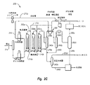
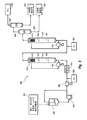
図2Cは、複数の沸騰床反応器を有する沸騰床水素処理システム200を概略的に示す。水素処理システム200は、その一例にLC−精製水素処理ユニットがあるが、原料214を改良するための直列の3つの沸騰床反応器210を含むことができる。原料214は、水素ガス216と共に第1の沸騰床反応器210aに導入されるが、これら原料214および水素ガス216の双方は、当該反応器に入る前にそれぞれの加熱器に通される。第1の沸騰床反応器210aからの改良された材料220aは、追加の水素ガス216と共に第2の沸騰床反応器210bに導入される。第2の沸騰床反応器210bからの改良された材料220bは、追加の水素ガス216と共に第3の沸騰床反応器210cに導入される。
FIG. 2C schematically shows a boiling bed
液体炭化水素と残留した分散金属硫化物触媒粒子とを含む不揮発性成分から低沸点留分およびガスを除去するために、第1と第2の反応器210a、210b間および/または第2と第3の反応器210b、210c間に、1又はそれ以上の段間分離器を任意選択的に介在させることができることを理解されたい。価値の高い燃料生成物ではあるがアスファルテンの貧溶媒である、ヘキサンおよびヘプタンなどの低級アルカンを除去することが望ましい場合がある。複数の反応器間で揮発性物質を除去することは、価値の高い生成物の生産性を高め、下流の反応器に供給される炭化水素液体留分中におけるアスファルテンの溶解度を増加させる。両方とも、水素処理システム全体の効率を高める。
Between the first and
第3の沸騰床反応器210cからの改良された材料220cは、揮発性留分と不揮発性留分とを分離する高温分離器242aに送られる。揮発性留分246aは、第1の沸騰床反応器210aに導入される前に水素ガス216を予熱する熱交換器250を通過する。幾分冷却された揮発性留分246aは中間温度分離器242bに送られる。中間温度分離器242bは、熱交換器250による冷却の結果として形成され得られる液体留分248bから残りの揮発性留分246bを分離する。残りの揮発性留分246bは下流の低温分離器246cへ送られ、気体留分252cと脱気された液体留分248cとにさらに分離される。
The improved material 220c from the third boiling
高温分離器242aからの液体留分248aは、中間温度分離器242bからの液体留分248bと共に、低圧分離器242dに送られる。低圧分離器242dは、脱気された液体留分248dから水素リッチガス252dを分離する。脱気された液体留分248dは、その後、低温分離器242cからの脱気された液体留分248cと混合され、生成物に分別される。低温分離器242cからの気体留分252cは、オフガス、パージガス、および水素ガス216に精製される。水素ガス216は、圧縮され、補給された水素ガス216aと混合されてから、熱交換器250を通過して第1の沸騰床反応器210aに原料216と共に導入され、或いは第2および第3の沸騰床反応器210bおよび210bに直接導入される。
The
図2Dは、図2Cに図示されたシステムと同様に、複数の沸騰床反応器を有する沸騰床水素処理システム200を概略的に示すものだが、段間分離器221が第2および第3の反応器210b、210c間に介在していることが示されている。図示するように、第2段反応器210bからの流出物は段間分離器221に入るが、当該段階分離器221は高圧、高温分離器とすることができる。分離器221からの液体留分は、ライン216からの再利用される水素の一部と併合される。段間分離器221からの蒸気留分は第3段反応器210cを迂回し、第3段反応器210cからの流出物と混合され、その後、高圧高温分離器242aに入る。
FIG. 2D schematically shows a boiling bed
これにより、最初の2つの反応器の段階で形成された、より軽くより飽和した成分は、第3段反応器210cを迂回可能になる。この利点は、(1)第3段反応器の蒸気負荷が減少し、残りの重質成分を転化させるための第3段反応器の容積利用率が増加すること、(2)第3段反応器210cにおいてアスファルテンを不安定化させ得る「反溶媒」成分(飽和物)の濃度が低下することである。
This allows the lighter, more saturated components formed in the first two reactor stages to bypass the
好ましい実施形態では、水素処理システムは、水素処理の酷度の低い形態である単なる水素化精製ではなく、水素化分解反応を促進するように構成され稼働される。水素化分解は、より大きな炭化水素分子の分子量の減少および/または芳香族化合物の開環のような炭素−炭素分子結合の破壊を伴う。一方、水素化精製は、主として不飽和炭化水素の水素化を含み、炭素−炭素分子結合の破壊が最小限であるか又は全くない。単なる水素化精製反応よりも水素化分解反応を促進するために、水素処理反応器は、好ましくは約750°F(399℃)〜約860°F(460℃)の範囲の温度で、より好ましくは約780°F(416°C)〜約830°F(443°C)の範囲の温度で稼働され、好ましくは約1000psig(6.9MPa)〜約3000psig(20.7MPa)の範囲の圧力で、より好ましくは約1500psig(10.3MPa)〜約2500psig(17.2MPa)の範囲の圧力で稼働され、また好ましくは約0.05hr−1〜約0.45hr−1の範囲の空間速度(例えば、1時間当たりの反応器容積に対する供給容積の比として定義される液体毎時空間速度(Liquid Hourly Space Velocity)またはLHSVで、より好ましくは約0.15hr−1〜約0.35hr−1の範囲の空間速度で稼働される。水素化分解と水素化精製との違いは、また、残油存転化率によっても表すことができる(水素化分解は、高沸点の炭化水素からより低沸点の炭化水素への実質的な転化をもたらすが、水素化精製では当該転化はない)。本明細書に開示される水素処理システムは、約40%〜約90%の範囲、好ましくは約55%〜約80%の範囲の残油転化率をもたらすことができる。好ましい転化率範囲は、典型的には、異なる原料間で処理の難易度が違ってくるために原料の種類に依存する。典型的には、本明細書に開示するような二元触媒システムを用いるように改良するのに先立って沸騰床反応器を稼働しているのと比べて、少なくとも約5%高い、好ましくは少なくとも約10%高い転化率となる。 In a preferred embodiment, the hydrogen treatment system is configured and operated to promote a hydrocracking reaction rather than merely hydropurification, which is a less severe form of hydrogen treatment. Hydrocracking involves a reduction in the molecular weight of larger hydrocarbon molecules and / or disruption of carbon-carbon molecular bonds such as ring opening of aromatic compounds. Hydropurification, on the other hand, primarily involves the hydrogenation of unsaturated hydrocarbons with minimal or no disruption of carbon-carbon molecular bonds. In order to accelerate the hydrocracking reaction over a simple hydrogen purification reaction, the hydrogen treatment reactor is preferably at a temperature in the range of about 750 ° F (399 ° C) to about 860 ° F (460 ° C). Operates at temperatures in the range of about 780 ° F (416 ° C) to about 830 ° F (443 ° C), preferably at pressures in the range of about 1000 psig (6.9 MPa) to about 3000 psig (20.7 MPa). , More preferably operated at a pressure in the range of about 1500 psig (10.3 MPa) to about 2500 psig (17.2 MPa), and more preferably a space velocity in the range of about 0.05 hr -1 to about 0.45 hr -1 (eg). Liquid Hourly Space VOSV, defined as the ratio of the supply volume to the reactor volume per hour, more preferably in the range of about 0.15 hr -1 to about 0.35 hr -1. It operates at a space velocity. The difference between hydrocracking and hydrorefining can also be expressed by the residual oil conversion rate (hydrocracking is from high boiling hydrocarbons to lower boiling hydrocarbons. Substantial conversion to, but not in hydropurification). The hydrogenation systems disclosed herein are in the range of about 40% to about 90%, preferably about 55% to about 80. A residual oil conversion rate in the range of% can be obtained. The preferred conversion rate range is typically dependent on the type of raw material due to the different difficulty of processing between different raw materials. , At least about 5% higher, preferably at least about 10% higher than running a boiling bed reactor prior to improving to use a dual catalyst system as disclosed herein. It becomes the conversion rate.
III.沸騰床水素処理反応器の改良
図3A、図3B、図3Cおよび図3Dは、二元触媒システムを用い、(例えば、粘度の低下、比重の低下、アスファルテン含有量の減少、炭素含有量の減少、硫黄含有量の減少、および沈降物含有量の減少のうちの1若しくはそれ以上によって測定される)改善された品質の減圧残油生成物を生成するように沸騰床反応器を改良する例示的な方法を示すフローダイアグラムである。
III. Improvements to the boiling bed hydrogen treatment reactor FIGS. 3A, 3B, 3C and 3D use a dual catalyst system (eg, reduced viscosity, reduced specific gravity, reduced asphaltene content, reduced carbon content). (Measured by one or more of the reduction in sulfur content, and reduction in sediment content) Illustrative modification of the boiling bed reactor to produce improved quality decompression residual oil products. It is a flow diagram showing various methods.
図3Aは、方法であって、(1)不均一触媒を用いて初期条件で重油を水素処理するように沸騰床反応器を初期的に稼働し、初期品質の減圧残油を生成する工程と、(2)分散金属硫化物触媒粒子を前記沸騰床反応器に添加して、不均一触媒と前記分散金属硫化物触媒粒子とを含む二元触媒システムを有する改良された反応器を形成する工程と、(3)前記二元触媒システムを用いて前記改良された沸騰床反応器を同等又はより高い酷度で稼働し、初期条件で稼働している時よりも改善された品質の減圧残油生成物を生成する工程とを有する方法を示すフローダイアグラムである。 FIG. 3A shows a method according to (1) a step of initially operating a boiling bed reactor so as to hydrogenate heavy oil under initial conditions using a non-uniform catalyst to generate initial quality decompressed residual oil. , (2) Dispersed metal sulfide catalyst particles are added to the boiling bed reactor to form an improved reactor having a dual catalytic system containing the heterogeneous catalyst and the dispersed metal sulfide catalyst particles. And (3) decompressed residual oil of improved quality than when the improved boiling bed reactor was operated with the same or higher severity using the dual catalyst system and operated under the initial conditions. It is a flow diagram which shows the method which has the step of producing a product.
いくつかの実施形態において、沸騰床反応器を初期条件で初期稼働する際に用いられる不均一触媒は、沸騰床反応器において典型的に用いられている市販の触媒である。効率を最大化するために、反応器の初期条件は、沈降物の形成および汚染が許容可能なレベル内に保たれる反応器酷度とすることが有利である。二元触媒システムを用いるように沸騰反応器を改良することなく反応器酷度を上昇させると、過度の沈降物形成および望ましくない装置の汚染がもたらされることがあり、それは通常ならば水素処理反応器およびその関連設備、例えばパイプ、塔、加熱器、不均一触媒および/または分離装置などのより頻繁な停止および清掃を必要とするはずである。 In some embodiments, the heterogeneous catalyst used in initial operation of the boiling bed reactor under initial conditions is a commercially available catalyst typically used in boiling bed reactors. In order to maximize efficiency, it is advantageous that the initial conditions of the reactor are reactor severity in which sediment formation and contamination are kept within acceptable levels. Increasing the reactor severity without modifying the boiling reactor to use a dual catalyst system can result in excessive sediment formation and undesired equipment contamination, which is usually a hydrogenation reaction. More frequent shutdowns and cleaning of vessels and related equipment such as pipes, towers, reactors, heterogeneous catalysts and / or separators should be required.
同様またはより厳しい酷度で沸騰床反応器を稼働しながらも、生成される減圧残油の品質を改善するために、前記沸騰床反応器は、不均一触媒と分散金属硫化物触媒粒子とを有する二元触媒システムを用いるように改良される。改善された品質の減圧残油生成物は、粘度の低下、比重の低下、アスファルテン含有量減少、炭素含有量の減少、硫黄含有量の減少、および沈降物の減少のうちの1若しくはそれ以上によって特徴付けられる。 In order to improve the quality of the vacuum residual oil produced while operating the boiling bed reactor with the same or more severe severity, the boiling bed reactor has a heterogeneous catalyst and dispersed metal sulfide catalyst particles. It is modified to use the dual catalytic system that it has. Improved quality vacuum residual oil products are produced by one or more of reduced viscosity, reduced specific density, reduced asphaltene content, reduced carbon content, reduced sulfur content, and reduced sediment. Characterized.
図3Bは、方法であって、(1)不均一触媒を用いて初期条件で重油を水素処理するように沸騰床反応器を初期的に稼働し、初期品質の減圧残油を生成する工程と、(2)分散金属硫化物触媒粒子を前記沸騰床反応器に添加して、不均一触媒と前記分散金属硫化物触媒粒子とを含む二元触媒システムを有する改良された反応器を形成する工程と、(3)前記二元触媒システムを用いて前記改良された沸騰床反応器を同等又はより高いスループットで稼働し、初期条件で稼働している時よりも改善された品質の減圧残油生成物を生成する工程とを有する方法を示すフローダイアグラムである。 FIG. 3B shows a method according to (1) a step of initially operating a boiling bed reactor so as to hydrogenate heavy oil under initial conditions using a non-uniform catalyst to generate initial quality decompressed residual oil. , (2) Dispersed metal sulfide catalyst particles are added to the boiling bed reactor to form an improved reactor having a dual catalytic system containing the heterogeneous catalyst and the dispersed metal sulfide catalyst particles. And (3) the improved boiling bed reactor is operated with the same or higher throughput using the dual catalyst system, and the reduced pressure residual oil generation of the improved quality is improved as compared with the operation under the initial conditions. It is a flow diagram which shows the method which has the process of producing a thing.
図3Cは、方法であって、(1)不均一触媒を用いて初期条件で重油を水素処理するように沸騰床反応器を初期的に稼働し、初期品質の減圧残油を生成する工程と、(2)分散金属硫化物触媒粒子を前記沸騰床反応器に添加して、不均一触媒と前記分散金属硫化物触媒粒子とを含む二元触媒システムを有する改良された反応器を形成する工程と、(3)前記二元触媒システムを用いて前記改良された沸騰床反応器を同等又はより高い転化率で稼働し、初期条件で稼働している時よりも改善された品質の減圧残油生成物を生成する工程とを有する方法を示すフローダイアグラムである。
図3Dは、方法であって、(1)不均一触媒を用いて初期条件で重油を水素処理するように沸騰床反応器を初期的に稼働し、初期品質の減圧残油を生成する工程と、(2)分散金属硫化物触媒粒子を前記沸騰床反応器に添加して、不均一触媒と前記分散金属硫化物触媒粒子とを含む二元触媒システムを有する改良された反応器を形成する工程と、(3)前記二元触媒システムを用いて前記改良された沸騰床反応器を同等又はより高い酷度、スループットおよび/または転化率で稼働し、初期条件で稼働している時よりも改善された品質の減圧残油生成物を生成する工程とを有する方法を示すフローダイアグラムである。
FIG. 3C shows a method of (1) initially operating a boiling bed reactor so as to hydrogenate heavy oil under initial conditions using a non-uniform catalyst to generate initial quality decompressed residual oil. , (2) Dispersed metal sulfide catalyst particles are added to the boiling bed reactor to form an improved reactor having a dual catalytic system containing the heterogeneous catalyst and the dispersed metal sulfide catalyst particles. And (3) reduced pressure residual oil of improved quality compared to when the improved boiling bed reactor was operated at the same or higher conversion rate using the dual catalyst system and operated under the initial conditions. It is a flow diagram which shows the method which has the step of producing a product.
FIG. 3D shows a method, in which (1) a boiling bed reactor is initially operated so as to hydrogenate heavy oil under initial conditions using a heterogeneous catalyst, and a step of producing decompressed residual oil of initial quality. , (2) Dispersed metal sulfide catalyst particles are added to the boiling bed reactor to form an improved reactor having a dual catalytic system containing the heterogeneous catalyst and the dispersed metal sulfide catalyst particles. And (3) using the dual catalyst system to operate the improved boiling bed reactor at the same or higher severity, throughput and / or conversion rate, and improved over initial conditions. It is a flow diagram which shows the method which has the step of producing the reduced pressure residual oil product of the said quality.
前記分散金属硫化物触媒粒子は、別々に生成され、その後、二元触媒システムを形成するときに沸騰床反応器に添加されてもよい。代替的に、または加えて、前記分散金属硫化物触媒粒子の少なくとも一部は、沸騰床反応器内の重油中でその場で生成され得る。 The dispersed metal sulfide catalyst particles may be generated separately and then added to the boiling bed reactor when forming a dual catalytic system. Alternatively, or in addition, at least some of the dispersed metal sulfide catalyst particles can be produced in situ in heavy oil in a boiling bed reactor.
いくつかの実施形態において、分散金属硫化物触媒粒子は、有利には、重油原料全体の中でその場で形成される。これは、まず触媒前駆体を重油原料全体と混合して調整された原料を形成し、その後、その調整済み原料を加熱して前記触媒前駆体を分解することによって達成することができ、これにより、触媒金属が、重油中および/または重油に添加された硫黄および/または硫黄含有分子と反応して前記分散金属硫化物触媒粒子が形成される。 In some embodiments, the dispersed metal sulfide catalyst particles are advantageously formed in situ within the entire heavy oil feedstock. This can be achieved by first mixing the catalyst precursor with the whole heavy oil raw material to form a prepared raw material, and then heating the adjusted raw material to decompose the catalyst precursor. , The catalyst metal reacts with sulfur and / or sulfur-containing molecules in and / or the heavy oil to form the dispersed metal sulfide catalyst particles.
前記触媒前駆体は、油溶性であってよく、また、約100℃(212°F)〜約350℃(662°F)の範囲、または約150℃(302°F)〜約300℃(572°F)の範囲、または約175℃(347°F)〜約250℃(482°F)の範囲の分解温度を有するものであってよい。例示的な触媒前駆体としては、適切な混合条件下で重油原料と混合した場合に実質的な分解を回避するのに十分な高さの分解温度または範囲を有する、有機金属錯体若しくは化合物、より具体的には油溶性化合物または遷移金属と有機酸の錯体が挙げられる。触媒前駆体を炭化水素油希釈剤と混合する場合、当該希釈剤を前記触媒前駆体の顕著な分解が起こる温度以下に維持することが有利である。当業者は、本開示に従い、前記分散金属硫化物触媒粒子の形成前に、実質的な分解を伴うことなく選択された前駆体組成物の均質な混合をもたらす混合温度プロファイルを選択することができる。 The catalyst precursor may be oil soluble and may range from about 100 ° C (212 ° F) to about 350 ° C (662 ° F) or from about 150 ° C (302 ° F) to about 300 ° C (572). It may have a decomposition temperature in the range of ° F) or in the range of about 175 ° C (347 ° F) to about 250 ° C (482 ° F). Exemplary catalyst precursors include organic metal complexes or compounds having a decomposition temperature or range high enough to avoid substantial decomposition when mixed with heavy oil feedstocks under appropriate mixing conditions. Specific examples thereof include an oil-soluble compound or a complex of a transition metal and an organic acid. When the catalyst precursor is mixed with a hydrocarbon oil diluent, it is advantageous to keep the diluent below a temperature at which significant degradation of the catalyst precursor occurs. Those skilled in the art can select a mixing temperature profile according to the present disclosure that results in a homogeneous mixing of the selected precursor composition prior to the formation of the dispersed metal sulfide catalyst particles without substantial decomposition. ..
例示的な触媒前駆体としては、2−エチルヘキサン酸モリブデン、オクタン酸モリブデン、ナフテン酸モリブデン、ナフテン酸バナジウム、オクタン酸バナジウム、ヘキサカルボニルモリブデン、ヘキサカルボニルバナジウム、およびペンタカルボニル鉄が挙げられるが、これらに限定されない。その他の触媒前駆体としては、複数のカチオン性モリブデン原子と少なくとも8個の炭素原子を有する複数のカルボキシレートアニオンとを有するモリブデン塩が挙げられ、それは(a)芳香族、(b)脂環式、または(c)分枝状、不飽和および脂肪族の少なくとも1つである。一例として、各カルボキシレートアニオンは、8〜17個の炭素原子または11〜15個の炭素原子を有してよい。前記カテゴリーの少なくとも1つに適合するカルボキシレートアニオンの例としては、3−シクロペンチルプロピオン酸、シクロヘキサン酪酸、ビフェニル−2−カルボン酸、4−ヘプチル安息香酸、5−フェニル吉草酸、ゲラン酸(3,7−ジメチル−2,6−オクタジエン酸)、およびそれらの組み合わせからなる群から選択されるカルボン酸から生成されるカルボキシレートアニオンが挙げられる。 Exemplary catalyst precursors include molybdenum 2-ethylhexanoate, molybdenum octanate, molybdenum naphthenate, vanadium naphthenate, vanadium octanate, hexacarbonyl molybdenum, hexacarbonyl vanadium, and pentacarbonyl iron. Not limited to. Other catalytic precursors include molybdenum salts having a plurality of cationic molybdenum atoms and a plurality of carboxylate anions having at least 8 carbon atoms, which are (a) aromatic, (b) alicyclic. , Or (c) at least one of branched, unsaturated and aliphatic. As an example, each carboxylate anion may have 8 to 17 carbon atoms or 11 to 15 carbon atoms. Examples of carboxylate anions that fit at least one of the above categories are 3-cyclopentylpropionic acid, cyclohexanebutyric acid, biphenyl-2-carboxylic acid, 4-heptylbenzoic acid, 5-phenylvaleric acid, geranic acid (3,). 7-Dimethyl-2,6-octadienic acid), and carboxylate anions produced from carboxylic acids selected from the group consisting of combinations thereof.
その他の実施形態では、油溶性で熱的に安定なモリブデン触媒前駆体化合物の生成に使用するためのカルボキシレートアニオンは、3−シクロペンチルプロピオン酸、シクロヘキサン酪酸、ビフェニル−2−カルボン酸、4−ヘプチル安息香酸、5−フェニル吉草酸、ゲラン酸(3,7−ジメチル−2,6−オクタジエン酸)、10−ウンデセン酸、ドデカン酸、およびそれらの組み合わせからなる群から選択されるカルボン酸から生成されるものである。前述のカルボン酸から生成されたカルボキシレートアニオンを用いて生成されたモリブデン触媒前駆体は改善された熱安定性を有することが見出された。 In other embodiments, the carboxylate anions for use in the production of oil-soluble and thermally stable molybdenum catalytic precursor compounds are 3-cyclopentylpropionic acid, cyclohexanebutyric acid, biphenyl-2-carboxylic acid, 4-heptyl. Produced from carboxylic acids selected from the group consisting of benzoic acid, 5-phenylvaleric acid, geranoic acid (3,7-dimethyl-2,6-octadienic acid), 10-undecenoic acid, dodecanoic acid, and combinations thereof. It is a thing. Molybdenum catalyst precursors produced using the carboxylate anions produced from the aforementioned carboxylic acids have been found to have improved thermal stability.
より高い熱安定性を有する触媒前駆体は、210℃より高い、約225℃より高い、約230℃より高い、約240℃より高い、約275℃より高い、または約290℃より高い第1の分解温度を有することができる。このような触媒前駆体は、250℃より高い、または約260℃より高い、または約270℃より高い、または約280℃より高い、または約290℃より高い、または約330℃より高いピーク分解温度を有することができる。 Catalyst precursors with higher thermal stability are first, higher than 210 ° C, higher than about 225 ° C, higher than about 230 ° C, higher than about 240 ° C, higher than about 275 ° C, or higher than about 290 ° C. Can have a decomposition temperature. Such catalyst precursors have a peak decomposition temperature above 250 ° C, or above about 260 ° C, or above about 270 ° C, or above about 280 ° C, or above about 290 ° C, or above about 330 ° C. Can have.
当業者は、本開示に従い、前記分散金属硫化物触媒粒子を形成する前に、実質的な分解を伴うことなく選択された前駆体組成物の均質な混合をもたらす混合温度プロファイルを選択することができる。 Those skilled in the art may select a mixing temperature profile that results in a homogeneous mixing of the selected precursor composition without substantial decomposition prior to forming the dispersed metal sulfide catalyst particles in accordance with the present disclosure. can.
触媒前駆体組成物を重油原料と直接混合することは本発明の範囲内であるが、そのような場合には、当該前駆体組成物の実質的な分解前に原料中で前記前駆組成物を十分に混合するのに十分な時間、前記組成物を混合するように注意しなければならない。例えば、Cyrらの米国特許第5,578,197号は、その開示が参照により組み込まれるが、得られた混合物が反応容器において加熱されて触媒化合物を形成し水素化分解をもたらす前に、2−エチルヘキサン酸モリブデンがビチューメン減圧塔残留物と24時間混合される方法が記載されている(第10欄、第4〜43行参照)。24時間の混合は試験環境下では十分に許容され得るが、そのような長い混合時間はある種の工業的稼働においては非常に費用がかかる。加熱して活性触媒を形成する前に重油中で触媒前駆体を確実に十分に混合するために、調整済み原料を加熱する前に一連の混合工程が異なる混合装置によって行われる。これらは、1若しくはそれ以上の低剪断インライン混合器と、それに続く1若しくはそれ以上の高剪断混合器と、それに続くサージ容器および周辺ポンプシステムと、それに続き供給流を水素処理反応器に導入する前に加圧する1若しくはそれ以上の多段高圧ポンプとを含んでもよい。
It is within the scope of the present invention to mix the catalyst precursor composition directly with the heavy oil raw material, but in such cases, the precursor composition may be mixed in the raw material prior to substantial decomposition of the precursor composition. Care must be taken to mix the composition for a sufficient amount of time to mix well. For example, Cyr et al., US Pat. No. 5,578,197, incorporates the disclosure by reference, but before the resulting mixture is heated in a reaction vessel to form a catalytic compound and result in hydrocracking, 2 A method of mixing molybdenum ethylhexanoate with the bitumen decompression tower residue for 24 hours is described (see
いくつかの実施形態において、調整済み原料は、重油内においてその場で分散金属硫化物触媒粒子の少なくとも一部を形成するために、水素処理反応器に入れられる前に加熱装置で予熱される。その他の実施形態では、前記調整済み原料は、重油内においてその場で分散金属硫化物触媒粒子の少なくとも一部を形成するために、水素処理反応器内で加熱またはさらに加熱される。 In some embodiments, the conditioned raw material is preheated in a heating device before being placed in a hydrogen treatment reactor to form at least a portion of the dispersed metal sulfide catalyst particles in situ in heavy oil. In other embodiments, the prepared raw material is heated or further heated in a hydrogen treatment reactor to form at least a portion of the dispersed metal sulfide catalyst particles in situ in the heavy oil.
いくつかの実施形態では、分散金属硫化物触媒粒子は多段階プロセスで形成することができる。例えば、油溶性触媒前駆体組成物を炭化水素希釈剤と予混合して希釈された前駆体混合物を形成することができる。適切な炭化水素希釈剤の例として、これに限られないが、減圧軽油(通常、360〜524℃(680〜975°F)の公称沸点を有する)、デカント油またはサイクル油(通常、360〜550℃(680−1022°F)の公称沸点を有する)、及び軽油(通常、200〜360℃(392〜680°F)の公称沸点を有する)、重油原料の一部、並びに通常約200℃より高い温度で沸騰するその他の炭化水素が挙げられる。 In some embodiments, the dispersed metal sulfide catalyst particles can be formed in a multi-step process. For example, the oil-soluble catalyst precursor composition can be premixed with a hydrocarbon diluent to form a diluted precursor mixture. Examples of suitable hydrocarbon diluents are, but are not limited to, vacuum gas oil (usually having a nominal boiling point of 360-524 ° C (680-975 ° F)), decant oil or cycle oil (usually 360-). It has a nominal boiling point of 550 ° C (680-1022 ° F)), and light oil (usually has a nominal boiling point of 200-360 ° C (392-680 ° F)), some heavy oil raw materials, and usually about 200 ° C. Other hydrocarbons that boil at higher temperatures include.
希釈された前駆体混合物を生成するために使用される炭化水素油希釈剤に対する触媒前駆体の比は、約1:500〜約1:1の範囲、または約1:150〜約1:2の範囲、または約1:100〜約1:5の範囲(例えば、1:100、1:50、1:30、または1:10)である。 The ratio of the catalyst precursor to the hydrocarbon oil diluent used to produce the diluted precursor mixture ranges from about 1: 500 to about 1: 1 or from about 1: 150 to about 1: 2. The range, or the range of about 1: 100 to about 1: 5 (eg, 1: 100, 1:50, 1:30, or 1:10).
希釈された前駆体混合物中の触媒金属(例えば、モリブデン)の量は、好ましくは、希釈された前駆体混合物の重量に対し、約100ppm〜約7000ppmの範囲、より好ましくは、約300ppm〜約4000ppmの範囲である。 The amount of catalytic metal (eg, molybdenum) in the diluted precursor mixture is preferably in the range of about 100 ppm to about 7000 ppm, more preferably about 300 ppm to about 4000 ppm, relative to the weight of the diluted precursor mixture. Is the range of.
触媒前駆体は、触媒前駆体組成物のかなりの部分が分解する温度を下回る温度で炭化水素希釈剤と有利に混合される。希釈された前駆体混合物を形成するため、混合は、約25℃(77°F)〜約250℃(482°F)の範囲、または約50℃(122°F)〜約200℃(392°F)の範囲、または約75℃(167°F)〜約150℃(302°F)の範囲の温度で行われる。希釈された前駆体混合物が形成される温度は、触媒前駆体の分解温度および/または利用されるその他の特性、および/もしくは炭化水素希釈剤の粘度などの特性に依存しうる。 The catalyst precursor is advantageously mixed with the hydrocarbon diluent at a temperature below the temperature at which a significant portion of the catalyst precursor composition decomposes. To form a diluted precursor mixture, the mixture may range from about 25 ° C (77 ° F) to about 250 ° C (482 ° F), or from about 50 ° C (122 ° F) to about 200 ° C (392 °). It is carried out at a temperature in the range of F), or in the range of about 75 ° C (167 ° F) to about 150 ° C (302 ° F). The temperature at which the diluted precursor mixture is formed may depend on the decomposition temperature of the catalytic precursor and / or other properties utilized, and / or properties such as the viscosity of the hydrocarbon diluent.
触媒前駆体は、炭化水素油希釈剤と、好ましくは、約0.1秒〜約5分間、または約0.5秒〜約3分間、または約1秒〜約1分間の範囲の時間混合される。実際の混合時間は、少なくとも部分的には、温度(すなわち、流体の粘度に影響する)および混合強度に依存する。混合強度は、少なくとも部分的には、例えばインライン静的混合器の段階数に依存する。 The catalyst precursor is mixed with the hydrocarbon oil diluent, preferably for a time ranging from about 0.1 seconds to about 5 minutes, or about 0.5 seconds to about 3 minutes, or about 1 second to about 1 minute. Ru. The actual mixing time depends, at least in part, on the temperature (ie, which affects the viscosity of the fluid) and the mixing intensity. The mixing strength depends, at least in part, on the number of stages of the inline static mixer, for example.
触媒前駆体を炭化水素希釈剤と予混合して希釈された前駆体混合物を形成することは、その後に重油原料と混合される際に、特に大規模な工業運営で必要とされる比較的短い時間で、触媒前駆体を原料中に十分かつ均質に混合するのに大いに役立つ。希釈された前駆体混合物を形成する工程は、(1)より極性の高い触媒前駆体とより疎水性の高い重油原料との間の溶解度の差を低減または排除すること、(2)触媒前駆体と重油原料との間のレオロジーの差を低減または排除すること、および/または(3)触媒前駆体分子を分解して、重油原料中でより容易に分散させられる炭化水素希釈剤内に溶質を形成することによって、混合時間全体を短縮する。 Premixing the catalyst precursor with a hydrocarbon diluent to form a diluted precursor mixture is relatively short, especially when mixed with heavy oil feedstock, especially in large industrial operations. Over time, it greatly helps to mix the catalyst precursor sufficiently and homogeneously into the raw material. The steps of forming a diluted precursor mixture are (1) reducing or eliminating the difference in solubility between the more polar catalytic precursor and the more hydrophobic heavy oil feedstock, and (2) the catalytic precursor. To reduce or eliminate the difference in polarity between and the heavy oil feedstock, and / or (3) decompose the catalyst precursor molecules to bring the solute into a hydrocarbon diluent that is more easily dispersed in the heavy fuel oil feedstock. By forming, the entire mixing time is shortened.
次いで、希釈された前駆体混合物は、重油原料と併合され、触媒前駆体を原料全体に分散させるのに十分な時間および様式で混合されて、調整済み原料を形成する。当該調整済み原料では、熱分解および活性金属硫化物触媒粒子の形成に先立って、触媒前駆体が重油中で十分に混合される。重油原料中で触媒前駆体を十分に混合するために、希釈された前駆体混合物および重油原料は、有利には、約0.1秒〜約5分間、または約0.5秒〜約5分間、または約0.5秒〜約3分間、または約1秒〜約3分間混合される。混合処理の強力度および/または剪断エネルギーを増大させることは一般的に十分な混合をもたらすのに必要となる時間を短縮する。 The diluted precursor mixture is then merged with the heavy oil feedstock and mixed in a time and manner sufficient to disperse the catalytic precursor throughout the feedstock to form a conditioned feedstock. In the prepared raw material, the catalyst precursor is sufficiently mixed in heavy oil prior to pyrolysis and formation of active metal sulfide catalyst particles. In order to adequately mix the catalyst precursor in the fuel oil feedstock, the diluted precursor mixture and the fuel oil feedstock are advantageously used for about 0.1 seconds to about 5 minutes, or about 0.5 seconds to about 5 minutes. , Or about 0.5 seconds to about 3 minutes, or about 1 second to about 3 minutes. Increasing the strength and / or shear energy of the mixing process generally reduces the time required to achieve sufficient mixing.
触媒前駆体および/または希釈された前駆体混合物と重油との十分な混合をもたらすのに使用可能な混合装置の例としては、これらに限られないが、高剪断混合、例えばプロペラ又タービン羽根車を用いて容器内で作られる混合;または複数のインライン静的混合器;インライン高剪断混合器と組み合わされた複数のインライン静的混合器;サージ容器が続くインライン高剪断混合器と組み合わせた複数のインライン静的混合器;1若しくはそれ以上の多段遠心ポンプが続く上記のものの組み合わせが挙げられる。 Examples of mixing devices that can be used to bring about sufficient mixing of the catalyst precursor and / or diluted precursor mixture with heavy oil are, but are not limited to, high shear mixing, eg propellers or turbine impellers. Mixtures made in-container using In-line static mixer; one or more multi-stage centrifugal pumps followed by a combination of the above.
いくつかの実施形態では、複数のチャンバを有する高エネルギーポンプを用いてバッチ式混合ではなく連続式混合を実施することができ、その中で触媒前駆体組成物および重油原料はポンプ輸送プロセス自体の一環として撹拌され混合される。前述の混合装置はまた、触媒前駆体を炭化水素希釈剤と混合して触媒前駆体混合物を形成する、上述した予混合処理に用いることができる。 In some embodiments, a high energy pump with multiple chambers can be used to perform continuous mixing rather than batch mixing, in which the catalyst precursor composition and heavy oil feedstock are the pump transport process itself. It is stirred and mixed as part. The above-mentioned mixing apparatus can also be used in the above-mentioned premixing process in which the catalyst precursor is mixed with a hydrocarbon diluent to form a catalyst precursor mixture.
室温で固体または極度に粘稠な重油原料の場合、そのような原料を加熱して軟化させ十分に低い粘度を有する原料を生成することにより、油溶性触媒前駆体が原料組成物内へ良好に混合されるようにすることが有利である。一般的に、重油原料の粘度を低下させることは原料内で油溶性前駆体組成物を十分かつ均質に混合するのに必要となる時間を短縮する。 In the case of heavy oil raw materials that are solid or extremely viscous at room temperature, the oil-soluble catalyst precursor is successfully incorporated into the raw material composition by heating and softening such raw materials to produce a raw material with a sufficiently low viscosity. It is advantageous to have them mixed. In general, reducing the viscosity of a heavy oil feedstock reduces the time required to sufficiently and homogeneously mix the oil-soluble precursor composition within the feedstock.
重油原料と、触媒前駆体および/または希釈された前駆体混合物は、調整済み原料を生じさせるため、有利には、約25℃(77°F)〜約350℃(662°F)の範囲、約50℃(122°F)〜約300℃(572°F)の範囲、または約75℃(167°F)〜約250℃(482°F)の範囲の温度で加熱される。 The heavy oil feedstock and the catalyst precursor and / or diluted precursor mixture yield a conditioned feedstock, thus advantageously in the range of about 25 ° C. (77 ° F) to about 350 ° C. (662 ° F). It is heated at a temperature in the range of about 50 ° C. (122 ° F) to about 300 ° C. (572 ° F), or from about 75 ° C. (167 ° F) to about 250 ° C. (482 ° F).
最初に希釈された前駆体混合物を形成することなく直接的に触媒前駆体を重油原料と混合する場合、触媒前駆体組成物の大半が分解される温度より低い温度で触媒前駆体と重油原料を混合することが有利である。しかしながら、触媒前駆体を炭化水素希釈剤と予混合して希釈された前駆体混合物を形成する場合、後にそれは重油原料と混合されるが、重油原料が触媒前駆体の分解温度以上になることが許容され得る。これは、炭化水素希釈剤が、個々の触媒前駆体分子を遮蔽し、それらが凝集してより大きな粒子を形成することを防止し、混合中の重油の熱から触媒前駆体分子を一時的に隔離し、かつ分解して金属を遊離させる前に重油原料全体への十分かつ迅速な触媒前駆体分子の分散を促進するためである。さらに、重油中の硫黄含有分子から硫化水素を遊離させて金属硫化物触媒粒子を形成させるために原料の更なる加熱が必要な場合がある。このようにして、触媒前駆体の斬新的な希釈は、重油原料内で高レベルの分散を可能にし、原料が触媒前駆体の分解温度を超える温度であっても、高い分散性の金属硫化物触媒粒子の形成をもたらす。 When the catalyst precursor is mixed directly with the heavy oil source without forming the initially diluted precursor mixture, the catalyst precursor and the heavy oil source are mixed at a temperature lower than the temperature at which most of the catalyst precursor composition is decomposed. It is advantageous to mix. However, when the catalyst precursor is premixed with a hydrocarbon diluent to form a diluted precursor mixture, which is later mixed with the heavy oil feedstock, the fuel oil feedstock may be above the decomposition temperature of the catalyst precursor. It can be tolerated. This prevents the hydrocarbon diluent from shielding the individual catalyst precursor molecules and allowing them to aggregate to form larger particles, temporarily removing the catalyst precursor molecules from the heat of the heavy oil during mixing. This is to facilitate sufficient and rapid dispersal of catalyst precursor molecules throughout the heavy oil source before sequestering and decomposing to liberate the metal. In addition, further heating of the raw material may be required to liberate hydrogen sulfide from sulfur-containing molecules in heavy oil to form metal sulfide catalyst particles. In this way, the novel dilution of the catalyst precursor allows for high levels of dispersion within the heavy oil feedstock and is a highly dispersible metal sulfide even at temperatures above the catalyst precursor decomposition temperature of the feedstock. It results in the formation of catalytic particles.
触媒前駆体を重油全体に十分に混合して調整済み原料を得た後、この組成物を加熱することにより、触媒前駆体の分解が引き起こされ、そこから触媒金属が遊離し、それが重油内の、および/または重油に添加された硫黄と反応して活性金属硫化物触媒粒子を形成する。触媒前駆体からの金属は最初に金属酸化物を形成し、その後、重油中の硫黄と反応して、最終的な活性触媒を形成する金属硫化化合物を生じる。重油原料が十分または過剰に硫黄を含む場合、硫黄をそこから遊離させるのに十分な温度で重油原料を加熱することにより、最終的な活性触媒をその場で形成することができる。いくつかの場合では、前駆体組成物が分解する温度で硫黄を遊離させることができる。その他の場合では、より高い温度にするため、更なる加熱が必要となる可能性がある。 After the catalyst precursor is thoroughly mixed with the whole heavy oil to obtain a conditioned raw material, heating this composition causes the catalyst precursor to decompose, from which the catalyst metal is liberated, which is contained in the heavy oil. And / or react with sulfur added to heavy oil to form active metal sulfide catalyst particles. The metal from the catalyst precursor first forms a metal oxide and then reacts with sulfur in heavy oil to give the final active catalyst, a metal sulfide compound. If the fuel oil feedstock contains sufficient or excess sulfur, the final active catalyst can be formed in situ by heating the fuel oil feedstock at a temperature sufficient to liberate the sulfur from it. In some cases, sulfur can be liberated at the temperature at which the precursor composition decomposes. In other cases, further heating may be required to reach higher temperatures.
触媒前駆体が重油全体に十分に混合されている場合、遊離した金属イオンの少なくとも大半は、他の金属イオンから十分に保護または遮蔽され、それにより、それらが硫黄と金属硫化化合物を形成する反応をすると、金属分子分散触媒が形成される。いつかの状況下では、微量の凝集が起こり、コロイドサイズの触媒粒子を生じる場合がある。しかしながら、触媒前駆体の熱分解に先立ち、原料全体に触媒前駆体を十分に混合する処理をすることで、コロイド粒子よりも個々の触媒分子が生成されると考えられる。触媒前駆体が十分に混合されずに単純にブレンドされる場合、触媒前駆体は原料と典型的には、ミクロンサイズ以上の大きな凝集金属硫化化合物の形成を引き起こす。 When the catalyst precursor is well mixed throughout the heavy oil, at least most of the free metal ions are well protected or shielded from other metal ions, thereby forming a reaction in which they form sulfur and a metal sulfide compound. Then, a metal molecule dispersion catalyst is formed. Under some circumstances, trace agglutination may occur, resulting in colloid-sized catalytic particles. However, it is considered that individual catalyst molecules are produced rather than colloidal particles by performing a treatment in which the catalyst precursor is sufficiently mixed with the whole raw material prior to the thermal decomposition of the catalyst precursor. If the catalyst precursors are not mixed well and are simply blended, the catalyst precursors cause the formation of large aggregate metal sulfide compounds, typically micron-sized or larger, with the raw material.
分散金属硫化物触媒粒子を形成するために、調整済み原料は、約275℃(527°F)〜約450℃(842°F)の範囲、または約310℃(590°F)〜約430℃(806°F)の範囲、または約330℃(626°F)〜約410℃(770°F)の範囲の温度にまで加熱される。 To form the dispersed metal sulfide catalyst particles, the adjusted raw material ranges from about 275 ° C (527 ° F) to about 450 ° C (842 ° F), or from about 310 ° C (590 ° F) to about 430 ° C. It is heated to a temperature in the range of (806 ° F) or in the range of about 330 ° C (626 ° F) to about 410 ° C (770 ° F).
分散金属硫化物触媒粒子により提供される触媒金属の初期濃度は、重油原料の重量に対し、約1ppm〜約500ppmの範囲、または約5ppm〜約300ppmの範囲、または約10ppm〜約100ppmの範囲とすることができる。触媒は、揮発性留分が残油留分から除去されるにつれて、より濃縮され得る。 The initial concentration of the catalytic metal provided by the dispersed metal sulfide catalyst particles ranges from about 1 ppm to about 500 ppm, or from about 5 ppm to about 300 ppm, or from about 10 ppm to about 100 ppm with respect to the weight of the heavy oil raw material. can do. The catalyst can be more concentrated as the volatile fraction is removed from the residual oil fraction.
重油原料に顕著な量のアスファルテン分子が含まれる場合、分散金属硫化物触媒粒子は、選択的にアスファルテン分子と結びつき、またはアスファルテン分子に非常に近接したままとなりうる。アスファルテン分子は一般的に重油中に含まれるその他の炭化水素より親水性が高く疎水性が低いため、アスファルテン分子は金属硫化物触媒粒子に対してより大きな親和性を有することができる。金属硫化物触媒粒子は親水性が非常に高い傾向にあるため、その個々の粒子または分子は重油原料内でより親水性の高い部分または分子の方へ移動する傾向にある。 If the heavy oil feedstock contains significant amounts of asphaltene molecules, the dispersed metal sulfide catalyst particles may selectively bind to or remain in close proximity to the asphaltene molecules. Since asphaltene molecules are generally more hydrophilic and less hydrophobic than other hydrocarbons contained in heavy oil, asphaltene molecules can have greater affinity for metal sulfide-catalyzed particles. Since metal sulfide catalyst particles tend to be very hydrophilic, their individual particles or molecules tend to move towards the more hydrophilic moieties or molecules within the heavy oil feedstock.
金属硫化物触媒粒子が有する高い極性の性質により、金属硫化物触媒粒子はアスファルテン分子と結び付き又は結び付くことが可能になる一方、極性の高い触媒化合物と疎水性を有する重油との間は一般的に非相溶性であり、活性触媒粒子の分解および形成に先立ち、前述した重油中での触媒前駆体組成物の均質または十分な混合が必要となる。金属触媒化合物は極性が高いため、それらを重油中に直接添加しても効果的に重油中に分散させることができない。実用面では、より小さな活性触媒粒子を形成することにより、より多くの数の触媒粒子が得られ、重油全体にわたってより均一に分布した触媒配置をもたらす。 The highly polar nature of the metal sulfide catalyst particles allows the metal sulfide catalyst particles to bind or bind to asphaltene molecules, while generally between highly polar catalyst compounds and hydrophobic heavy oils. It is incompatible and requires homogeneous or sufficient mixing of the catalyst precursor composition in the heavy oils described above prior to the decomposition and formation of the active catalyst particles. Due to the high polarity of metal catalyst compounds, even if they are added directly to heavy oil, they cannot be effectively dispersed in heavy oil. In practical terms, forming smaller active catalyst particles results in a larger number of catalyst particles, resulting in a more uniformly distributed catalyst arrangement throughout the heavy oil.
IV.改良された沸騰床反応器
図4は、本明細書に開示される方法およびシステムで用いられる改良された沸騰床水素処理システム400の一例を概略的に示す。沸騰床水素処理システム400は、改良された沸騰床反応器430と、高温分離器404(または蒸留塔のようなその他の分離器)とを含む。改良された沸騰床反応器430を形成するために、触媒前駆体402がまず1若しくはそれ以上の混合器406中で炭化水素希釈剤404と予混合されて、触媒前駆体混合物409を形成する。触媒前駆体混合物409は原料408に添加され、1若しくはそれ以上の混合器410において原料と混合されて、調整済み原料411を形成する。調整済み原料は周辺ポンプ414を伴うサージ容器412に供給されて、調整済み原料内において触媒前駆体の更なる混合および分散がもたらされる。
IV. Improved Boiling Bed Reactor FIG. 4 schematically shows an example of an improved boiling bed
サージ容器412からの調整済み原料は、1若しくはそれ以上のポンプ416によって加圧され、予熱器418を通過し、加圧された水素ガス420と共に、沸騰床反応器430の底部又はその近くに位置する注入ポート436を介して沸騰床反応器430に供給される。沸騰床反応器430内の重油材料426は、触媒粒子424として概略的に示された分散金属硫化物触媒粒子を含有する。
The conditioned material from the
重油原料408は、その中に、これに限られないが、重質原油、油砂瀝青、原油からのバレル留分の底部、常圧塔底、減圧塔底、コールタール、液化石炭、およびその他の残油留分の1若しくはそれ以上を含む任意の所望の化石燃料の原料および/または留分であってよい。いくつかの実施形態では、重油原料408は、かなりの割合で高沸点炭化水素(すなわち公称上343℃(650°F)以上、より具体的には、公称上約524℃(975°F)以上)および/またはアスファルテンを含みうる。アスファルテンは炭素に対する水素の割合が比較的低い複合炭化水素分子であるが、これは、パラフィン系側鎖を伴う相当数の縮合芳香族およびナフテン環を有するためである(図1参照)。縮合芳香族およびナフテン環からなる複数の層は、硫黄または窒素のようなヘテロ原子、並びに/または、ポリメチレン架橋、チオエーテル結合、およびバナジウムおよびニッケル錯体によって共に保持される。アスファルテン留分もまた、原油または残りの減圧残油よりも高い含有量で硫黄および窒素を含有し、また、より高濃度の炭素形成化合物(すなわち、コークス前駆体および沈降物を形成する)を含有する。 Heavy oil raw material 408 includes, but is not limited to, heavy crude oil, oil sands bitumen, bottom of barrel fractions from crude oil, normal pressure tower bottom, decompression tower bottom, coal tar, liquefaction coal, and others. It may be a raw material and / or a fraction of any desired fossil fuel containing one or more of the residual oil distillates of. In some embodiments, the fuel oil feedstock 408 has a significant proportion of high boiling hydrocarbons (ie, nominally 343 ° C (650 ° F) or higher, more specifically, nominally about 524 ° C (975 ° F) or higher. ) And / or may include asphaltene. Asphaltene is a complex hydrocarbon molecule with a relatively low ratio of hydrogen to carbon because it has a significant number of fused aromatics and naphthenic rings with paraffinic side chains (see Figure 1). Multiple layers of fused aromatics and naphthenic rings are retained together by heteroatoms such as sulfur or nitrogen, and / or by polymethylene crosslinks, thioether bonds, and vanadium and nickel complexes. The asphaltene fraction also contains sulfur and nitrogen at a higher content than the crude oil or the remaining vacuum residual oil, and also contains higher concentrations of carbon-forming compounds (ie, forming coke precursors and precipitates). do.
沸騰床反応器430は、不均一触媒444を有する膨張触媒領域442をさらに含む。下部不均一触媒不含領域448は膨張触媒領域442の下に位置し、上部不均一触媒不含領域450は膨張触媒領域442の上に位置する。分散金属硫化物触媒粒子424は、膨張触媒領域442と不均一触媒不含領域448、450、452とを含む沸騰床反応器430内の材料426全体に分散されており、それによって、二元触媒システムを含むように改良するのに先立ち、沸騰床反応器の触媒不含領域を構成する範囲内において改良する反応を促進することができる。
The boiling
単なる水素化反応よりも水素化分解を促進するために、水素処理反応器は、好ましくは約750°F(399℃)〜約860°F(460℃)の範囲の温度で、より好ましくは約780°F(416°C)〜約830°F(443°C)の範囲の温度で稼働され、好ましくは約1000psig(6.9MPa)〜約3000psig(20.7MPa)の範囲の圧力で、より好ましくは約1500psig(10.3MPa)〜約2500psig(17.2MPa)の範囲の圧力で稼働され、また好ましくは約0.05hr−1〜約0.45hr−1の範囲の空間速度(LHSV)で、より好ましくは約0.15hr−1〜約0.35hr−1の範囲の空間速度で稼働される。水素化分解と水素化精製との間の違いは、残油転化率によっても表すことができる(水素化分解は高沸点の炭化水素からより低沸点の炭化水素への実質的な転化をもたらすが、水素化精製では当該転化は起こらない)。本明細書に開示される水素処理システムは、約40%〜約90%の範囲、好ましくは約55%〜約80%の範囲の残油転化率をもたらすことができる。好ましい転化率の範囲は、典型的には、異なる原料間で処理の難易度が違ってくるために、原料の種類に依存する。典型的には、本明細書に開示する二元触媒システムを用いるように改良する前に沸騰床反応器を稼働しているのと比べて、少なくとも約5%高い、好ましくは少なくとも約10%高い転化率となる。 In order to promote hydrocracking more than a simple hydrogenation reaction, the hydrogenation reactor is preferably at a temperature in the range of about 750 ° F (399 ° C) to about 860 ° F (460 ° C), more preferably about. It is operated at a temperature in the range of 780 ° F (416 ° C) to about 830 ° F (443 ° C), preferably at a pressure in the range of about 1000 psig (6.9 MPa) to about 3000 psig (20.7 MPa). It is preferably operated at a pressure in the range of about 1500 psig (10.3 MPa) to about 2500 psig (17.2 MPa) and preferably at a spatial velocity (LHSV) in the range of about 0.05 hr -1 to about 0.45 hr -1. , More preferably, it is operated at a space velocity in the range of about 0.15 hr -1 to about 0.35 hr -1. The difference between hydrocracking and hydrorefining can also be expressed by the residual oil conversion rate (although hydrocracking results in a substantial conversion from high boiling hydrocarbons to lower boiling hydrocarbons. , The conversion does not occur in hydrocarbon purification). The hydrogen treatment systems disclosed herein can provide residual oil conversion rates in the range of about 40% to about 90%, preferably in the range of about 55% to about 80%. The range of preferred conversion rates will typically depend on the type of raw material due to the different levels of processing difficulty between the different raw materials. Typically, it is at least about 5% higher, preferably at least about 10% higher than running the boiling bed reactor prior to the modification to use the dual catalytic system disclosed herein. It becomes the conversion rate.
沸騰床反応器430内の材料426は、沸騰ポンプ454に接続された再循環流路452によって、上部不均一触媒不含領域450から下部不均一触媒不含領域448へ連続的に再循環される。再循環流路452の頂部には漏斗形状の再循環カップ456が設けられてなり、当該再循環カップ456を通じて上部不均一触媒不含領域450から材料426が引き込まれる。再利用される材料426は、新鮮な調整済み原料411および水素ガス420と混合される。
The material 426 in the boiling
新鮮な不均一触媒444は触媒入口管458を介して沸騰床反応器430反応器に導入され、使用済み不均一触媒444は触媒抜取管460を通して回収される。触媒抜取管460は、十分に使用された触媒と、部分的に使用されたが活性のある触媒と、新しく添加された触媒とを区別することができないが、分散金属硫化物触媒粒子424の存在は、膨張触媒領域442、再循環流路452、および下部および上部不均一触媒不含領域448、450内で、更なる触媒の活性化をもたらす。不均一触媒444の外側における炭化水素への水素の追加は、しばしば不均一触媒を失活させる原因となる沈降物およびコークス前駆体の形成を最小限にする。
The fresh
沸騰床反応器430は、頂部またはその付近に排出ポート438をさらに含み、当該排出ポート438を介して転化された材料440が抜き取られる。転化された材料440は高温分離器又は蒸留塔404内へ導入される。高温分離器または蒸留塔404は1若しくはそれ以上の揮発性留分405を残油留分407から分離する。当該揮発性留分は高温分離器404の頂部から回収され、残油留分407は高温分離器または蒸留塔404の底部から回収される。残油留分407には触媒粒子424として概略的に示す残留金属硫化物触媒粒子が含まれる。所望であれば、残油留分407の少なくとも一部を沸騰床反応器430に戻して、供給材料の一部を形成し、追加の金属硫化物触媒粒子を供給することができる。代替的に、残油留分407は、別の沸騰床反応器などの下流処理装置を用いてさらに処理することができる。この場合、分離器404は段間分離器とすることができる。
The boiling
いくつかの実施形態において、改善された品質の減圧残油生成物を生成する間に、改良された沸騰床反応器を同様のまたはそれ以上の酷度および/またはスループットで稼働することにより、沸騰床反応器を初期的に稼働する時と比べて装置の汚染度が同等以下となる。一般的に、減圧残油生成物の品質の改善は、粘度、アスファルテン含有量、炭素含有量、沈降物含有量、窒素含有量、および硫黄含有量のうちの1若しくはそれ以上を減少させることによって装置の汚染を低減することができる。 In some embodiments, boiling is performed by operating the improved boiling bed reactor at similar or higher severity and / or throughput while producing a reduced quality decompression residual oil product. The degree of contamination of the equipment is equal to or less than that when the floor reactor is initially operated. In general, improving the quality of vacuum residual oil products is by reducing one or more of the viscosity, asphaltene content, carbon content, sediment content, nitrogen content, and sulfur content. The contamination of the device can be reduced.
V.改善された品質の減圧残油
本明細書に開示されるように、二元触媒システムを用いるように沸騰床水素処理システムを改良することは、重油を改良し、より軽くより価値の高い留分を除去した後に残る減圧残油の品質を実質的に改善し得る。改善された品質の減圧残油生成物は、粘度、比重(増加したAPI比重)、アスファルテン含有量、炭素含有量、硫黄含有量、および沈降物含有量の1若しくはそれ以上の減少によって特徴付けられる。
V. Improved quality decompressed residual oil As disclosed herein, improving the boiling bed hydrogen treatment system to use a dual catalytic system improves heavy oil and makes it a lighter and more valuable fraction. The quality of the decompressed residual oil remaining after the removal of the oil can be substantially improved. Improved quality vacuum residual oil products are characterized by a one or more reduction in viscosity, specific gravity (increased API gravity), asphaltene content, carbon content, sulfur content, and sediment content. ..
いくつかの実施形態では、改善された品質の減圧残油生成物は、沸騰床反応器を初期的に稼働する時と比べて、少なくとも10%、15%、20%、25%、30%、40%、50%、60%、または70%の粘度の低下(例えば、300°Fでのブルックフィールド粘度によって測定される)によって特徴付けられる。 In some embodiments, the reduced quality decompression residual oil product is at least 10%, 15%, 20%, 25%, 30%, compared to when the boiling bed reactor is initially operational. It is characterized by a 40%, 50%, 60%, or 70% decrease in viscosity (eg, measured by Brookfield viscosity at 300 ° F).
いくつかの実施形態では、改善された品質の減圧残油生成物は、沸騰床反応器を初期的に稼働する時と比べて、少なくとも5%、7.5%、10%、12.5%、15%、20%、25%、または30%のアスファルテン含有量の減少によって特徴付けられる。 In some embodiments, the reduced quality decompression residual oil product is at least 5%, 7.5%, 10%, 12.5% compared to when the boiling bed reactor is initially operational. , 15%, 20%, 25%, or 30%, characterized by a reduction in asphaltene content.
いくつかの実施形態では、改善された品質の減圧残油生成物は、沸騰床反応器を初期的に稼働する時と比べて、少なくとも2%、4%、6%、8%、10%、12.5%、15%、または20%の微小残留炭素含有量の減少(例えば、MCR含有量によって測定される)によって特徴付けられる。 In some embodiments, the reduced quality decompression residual oil product is at least 2%, 4%, 6%, 8%, 10%, compared to when the boiling bed reactor is initially operational. It is characterized by a 12.5%, 15%, or 20% reduction in microremaining carbon content (eg, as measured by MCR content).
いくつかの実施形態では、改善された品質の減圧残油生成物は、沸騰床反応器を初期的に稼働する時と比べて、少なくとも5%、7.5%、10%、15%、20%、25%、30%、または35%の硫黄含有量の減少によって特徴付けられる。 In some embodiments, the reduced quality decompression residual oil product is at least 5%, 7.5%, 10%, 15%, 20 compared to when the boiling bed reactor is initially operational. It is characterized by a reduction in sulfur content of%, 25%, 30%, or 35%.
いくつかの実施形態では、改良された品質の減圧残油生成物は、沸騰床反応器を初期的に稼働する時と比べて、少なくとも0.4、0.6、0.8、1.0、1.3、1.6、2.0、2.5、または3.0の°API比重の増加として表すことができる密度の減少によって特徴付けられる。 In some embodiments, the improved quality decompression residual oil product is at least 0.4, 0.6, 0.8, 1.0 compared to when the boiling bed reactor is initially operational. , 1.3, 1.6, 2.0, 2.5, or 3.0, characterized by a decrease in density, which can be expressed as an increase in the ° API gravity.
いくつかの実施形態では、改善された品質の減圧残油生成物は、沸騰床反応器を初期的に稼働する時と比べて、少なくとも2%、4%、6%、8%、10%、12.5%、15%、または20%の沈降物含有量の減少によって特徴付けられる。 In some embodiments, the reduced quality decompression residual oil product is at least 2%, 4%, 6%, 8%, 10%, compared to when the boiling bed reactor is initially operational. It is characterized by a 12.5%, 15%, or 20% reduction in sediment content.
一般的に、減圧残油生成物は、(1)燃料油、(2)溶媒脱アスファルト化、(3)コーキング、(4)発電プラント燃料、および/または(5)部分酸化(例えば、水素を発生させるためのガス化)に用いられる。減圧残油生成物に許容される汚染物質量の制限のために、本明細書に開示される二元触媒系水素処理システムを用いてその品質を改善することにより、減圧残油を規格内にするのに必要とされる高価なカッターストックの量を減らすことができる。それはまた、水素処理システム全体の効率的な稼働のためにその他の場所でカッターストックが必要とされるプロセス全体の負担も軽減する。 In general, decompressed residual oil products are (1) fuel oil, (2) solvent deasphaltification, (3) caulking, (4) power plant fuel, and / or (5) partial oxidation (eg, hydrogen). Used for gasification to generate). To limit the amount of contaminants allowed in decompressed residual oil products, depressurized residual oil is within specifications by improving its quality using the dual catalytic hydrogen treatment system disclosed herein. The amount of expensive cutter stock required to do this can be reduced. It also reduces the overall process burden that requires cutter stock elsewhere for efficient operation of the entire hydrogen treatment system.
沸騰床ユニットからの結果物は、非二元触媒稼働と比べて少なくとも同等以上の転化生成物の生成速度を維持しながらも、二元触媒システムの使用を通じて改良された品質で底部生成物(すなわち、減圧塔底、VTB、燃料油)が生成されることを示している。 The result from the boiling bed unit is a bottom product (ie, a bottom product) with improved quality through the use of a dual catalyst system, while maintaining at least the same or higher conversion product formation rate as compared to non-dual catalyst operation. , Decompression tower bottom, VTB, fuel oil).
さらに、二元触媒システムを用いるように沸騰床を改良すると、転化生成物の生成速度が上昇して初期条件を実質的に上回る場合でも底部生成物は少なくとも同等の品質に保たれる。通常ならば二元触媒システムを用いないと品質が低下するはずである。 In addition, improving the boiling bed to use a two-way catalytic system will keep the bottom product at least as good as the initial conditions, even if the conversion rate increases substantially above the initial conditions. Normally, quality should deteriorate without the use of a two-way catalytic system.
所与の沸騰床システムでは、転化生成物の生成速度は、減圧塔底生成物の品質に関する最小要件によって制限され得る。その他の事項は同じ場合(通常、反応器の温度、スループットおよび残油転化率の増加の組み合わせによって)生成速度が増加するにつれて、底部生成物の品質は低下し、ある時点で底部生成物の販売または使用を統制する要件または規格を下回ることとなる。これが発生すると、底部生成物の販売による価値の損失のため、製油所全体の稼働において経済面で悪影響を受ける。その結果、製油所は、許容可能な品質の底部生成物が確実に生成されるように、沸騰床システムの動作を調整することとなる。二元触媒システムの使用により管理者は経済的な実行可能性を維持することができる。 In a given boiling bed system, the rate of conversion product formation can be limited by the minimum requirements for the quality of decompression benthic products. If everything else is the same (usually due to a combination of increased reactor temperature, throughput and residual oil conversion rate), as the rate of formation increases, the quality of the bottom product deteriorates and at some point the bottom product is sold. Or it will fall below the requirements or standards that control its use. When this happens, the loss of value due to the sale of bottom products has a negative economic impact on the operation of the entire refinery. As a result, the refinery will adjust the operation of the boiling bed system to ensure that bottom products of acceptable quality are produced. The use of a two-way catalytic system allows the administrator to maintain economic feasibility.
二元触媒システムでは、二元触媒システムを用いない比較可能な条件下で予想されるものと比較して、底部生成物の品質が改善される。これにより、沸騰床管理者はユニット稼働において柔軟性を高めることができる。例えば、沸騰床ユニットを、底部品質の正味の改善をもたらすような様式で稼働させることができる。これは、より付加価値の高い使用上の材料の規格を満たすことにより、底部生成物をより高い価格で販売することができるという点で経済的な利点をもたらす。あるいは、沸騰床ユニットは、少なくとも同等の底部品質を維持しながら、転化生成物の生成速度をより高くすることができる。これは、底部生成物の市場性に悪影響を及ぼすことなく、価値の高い転化生成物(ナフサ、ディーゼル、減圧軽油)の販売を増加させることによって経済的な利点をもたらす。 The two-way catalytic system improves the quality of the bottom product compared to what is expected under comparable conditions without the two-way catalyst system. This allows the boiling bed manager to increase flexibility in unit operation. For example, the boiling floor unit can be operated in a manner that results in a net improvement in bottom quality. This provides an economic advantage in that the bottom product can be sold at a higher price by meeting the standards for higher value-added materials for use. Alternatively, the boiling bed unit can have a higher rate of conversion product formation while maintaining at least comparable bottom quality. This brings economic benefits by increasing the sales of high value conversion products (naphtha, diesel, desalinated gas oil) without adversely affecting the marketability of the bottom products.
転化生成物の生成速度は「反応器酷度」の増加によって高めることができる。当該「反応器酷度」とは、反応器の温度と、スループットと、反応器全体の性能を決める残油転化率との組み合わせである。反応器酷度の増加、したがって生成速度の増加は、(a)一定のスループットでの温度/転化率の上昇、(b)一定の転化率でのスループット/温度の上昇、並びに(c)スループット、温度、および転化率の上昇などの条件変化の様々な組合せによって達成することができる。 The rate of conversion product formation can be increased by increasing the "reactor severity". The "reactor severity" is a combination of the reactor temperature, the throughput, and the residual oil conversion rate that determines the performance of the entire reactor. Increased reactor severity, and thus increased production rate, is (a) increased temperature / conversion at constant throughput, (b) increased throughput / temperature at constant conversion, and (c) throughput, It can be achieved by various combinations of temperature and conditional changes such as increased conversion rates.
減圧塔底生成物の粘度は、cP(センチポアズ)の単位で測定される場合が多い。二元触媒の使用による粘度変化の大きさは、重油原料の種類および沸騰床稼働条件を含む複数の因子に依存する。転化生成物の生成速度が等しい条件下では、二元触媒は減圧塔底部の粘度を次のように低下させることが示されている:
‐ウラル減圧残油原料の場合、40〜50%;
‐アラブミディウム減圧残油原料の場合、30〜50%;
‐アサバスカ減圧残油原料の場合、60〜70%;
‐マヤ常圧残油原料の場合、40〜50%。
The viscosity of decompression column benthic products is often measured in units of cP (centipores). The magnitude of the viscosity change due to the use of the two-way catalyst depends on multiple factors including the type of heavy oil raw material and the operating conditions of the boiling bed. Under conditions of equal conversion rates, the two-way catalyst has been shown to reduce the viscosity of the bottom of the decompression column as follows:
-For Ural decompression residual oil raw material, 40-50%;
-30% to 50% for Arabmidium decompression residual oil raw material;
-60-70% for Athabaskan decompression residual oil raw material;
-For Maya normal pressure residual oil raw material, 40 to 50%.
VTB生成物のAPI比重は、度合いとしてAPI比重(°)が測定される。API比重は、材料の比重と、化学式:SG(60F)=141.5/(API比重+13.1.5)という関係がある。VTB生成物は、高密度、低API比重であり、比重はゼロに近いか、またはゼロ未満である。転化生成物の生成速度が等しい条件下では、二元触媒システムは、減圧塔底のAPI比重を次のように増加させることが示されている:
‐アラブミディウム減圧残油原料の場合、〜1°API
‐アサバスカ減圧残油原料の場合、最大10°API;
‐マヤ常圧残油原料の場合、〜0.2°API。
The API gravity (°) of the VTB product is measured as a degree. The API gravity has a relationship between the specific gravity of the material and the chemical formula: SG (60F) = 141.5 / (API gravity + 13.1.5). The VTB product has a high density, low API gravity, with a density close to or less than zero. Under conditions of equal conversion rates, the two-way catalytic system has been shown to increase the API gravity of the bottom of the decompression tower as follows:
-For Arab Midium decompression residual oil raw material, ~ 1 ° API
-Up to 10 ° API for Athabaskan decompression residual oil raw material;
-For Maya atmospheric pressure residual oil raw material, ~ 0.2 ° API.
アスファルテン含有量は、重量パーセント含有量で測定することができ、ヘプタン不溶分とトルエン不溶分との差として定義することができる。このように定義されたアスファルテンは、一般に「C7アスファルテン」と言われる。別の定義としては、ペンタン不溶分からトルエン不溶分を引いたものが挙げられ、一般に「C5アスファルテン」と言われる。以下の実施例では、C7アスファルテンの定義が用いられる。 The asphaltene content can be measured in weight percent content and can be defined as the difference between the insoluble heptane and the insoluble toluene. The defined asphaltenes as is commonly referred to as "C 7 asphaltenes". Another definition, minus the toluene insolubles from pentane insolubles and the like, are commonly referred to as "C 5 asphaltenes". In the following examples, C 7 asphaltenes definitions are used.
転化生成物の生成速度が等しい条件下では、二元触媒システムはVTB生成物のアスファルテン含有量を次のように減少させることが示されている:
‐ウラル減圧残油原料の場合、15〜20%(相対);
‐アラブミディウム減圧残油原料の場合、少なくとも30〜40%(相対);
‐アサバスカ減圧残油原料の場合、〜50%(相対)。
Under conditions of equal conversion rate, the two-way catalytic system has been shown to reduce the asphaltene content of the VTB product as follows:
-In the case of Ural decompression residual oil raw material, 15 to 20% (relative);
-At least 30-40% (relative) for Arabmidium decompression residual oil raw material;
-In the case of Athabaskan decompression residual oil raw material, ~ 50% (relative).
残留炭素含有量は、微小残留炭素(microcarbon residue:MCR)またはコンラドソン残留炭素(Conradson carbon residue:CCR)法による重量パーセント含有量で測定される。転化生成物の生成速度が等しい条件下では、二元触媒システムはVTB生成物のMCR含有量を以下のように減少させることが示されている:
‐ウラル減圧残油原料の場合、10〜15%(相対);
‐アサバスカ減圧残油原料の場合、〜30%(相対)。
Residual carbon content is measured by weight percent content by the microcarbon reserve (MCR) or Konradson carbon reserve (CCR) method. Under conditions of equal conversion rate of conversion products, the two-way catalytic system has been shown to reduce the MCR content of VTB products as follows:
-For Ural decompression residual oil raw material, 10 to 15% (relative);
-In the case of Athabaskan decompression residual oil raw material, ~ 30% (relative).
硫黄含有量は、重量パーセント含有量で測定される。転化生成物の生成速度が等しい条件下では、二元触媒システムはVTB生成物の硫黄含有量を次のように減少させることが示されている:
‐ウラル減圧残油原料の場合、〜30%(相対);
‐アラブミディウム減圧残油原料の場合、25−30%(相的);
‐アサバスカ減圧残油原料の場合、最大40%(相対)。
Sulfur content is measured by weight percent content. Under conditions of equal conversion rate, the two-way catalytic system has been shown to reduce the sulfur content of VTB products as follows:
-In the case of Ural decompression residual oil raw material, ~ 30% (relative);
-In the case of Arabmidium decompression residual oil raw material, 25-30% (phase);
-Up to 40% (relative) for Athabaskan decompression residual oil raw materials.
VI.実験研究及び結果
以下の試験的研究は、重油を水素処理する際に、不均一触媒と分散金属硫化物触媒粒子と有する二元触媒システムを用いるように沸騰床反応器を改良することの効果および利点を実証するものである。具体的には、この試験的研究は、本発明の利用によって達成することができる減圧残油生成物の品質の改善を実証する。この試験のために図5のようにパイロットプラントが設計された。図5に概略的に示すように、直列に接続された2つの沸騰床反応器512,512'を備えたパイロットプラント500を用いて、重油原料を処理する際に不均一触媒を単独で用いる場合と、不均一系触媒を分散金属硫化物(すなわち、分散二硫化モリブデン触媒粒子)と組み合わせたものを有する二元触媒システムを用いる場合の差を判定した。
VI. Experimental studies and results The following experimental studies show the effects of modifying the boiling bed reactor to use a two-way catalytic system with heterogeneous catalysts and dispersed metal sulfide catalyst particles when hydrogenating heavy oils. It demonstrates the benefits. Specifically, this experimental study demonstrates the improvement in quality of decompression residual oil products that can be achieved by utilizing the present invention. A pilot plant was designed for this test as shown in FIG. As schematically shown in FIG. 5, when a heterogeneous catalyst is used alone when processing a heavy oil raw material using a
以下の試験的研究のために、重質減圧軽油を炭化水素希釈剤として用いた。調整済み原料中への分散触媒の目標通りの投入を達成するために、前駆体混合物は、一定量の触媒前駆体を一定量の炭化水素希釈剤と混合して触媒前駆体混合物を形成し、次いで一定量の触媒前駆体混合物を一定量の重油原料と混合することによって調製した。具体例として、(この場合、投入は金属濃度に基づいて表されるが)調整済み原料に30ppmの分散金属硫化物触媒を目標投入する1試験研究のため、触媒前駆体混合物を3000ppmの金属濃度で調製した。 Heavy vacuum gas oil was used as a hydrocarbon diluent for the following experimental studies. In order to achieve the targeted introduction of the dispersion catalyst into the conditioned raw material, the precursor mixture mixes a certain amount of catalyst precursor with a certain amount of hydrocarbon diluent to form a catalyst precursor mixture. It was then prepared by mixing a certain amount of catalyst precursor mixture with a certain amount of heavy oil raw material. As a specific example, the catalyst precursor mixture has a metal concentration of 3000 ppm for one test study in which a 30 ppm dispersed metal sulfide catalyst is targeted to the adjusted raw material (in this case, the input is expressed based on the metal concentration). Prepared in.
実際の試験における原料および稼働条件は、以下でより詳細に特定する。不均一触媒は沸騰反応器で一般的に用いられている市販の触媒である。分散金属硫化物触媒を用いない比較試験用に、希釈された前駆体混合物を用いる場合と同じ割合で炭化水素希釈剤(重質減圧軽油)を重油原料に添加した。これにより、二元触媒システムを用いる試験と不均一(沸騰床)触媒のみを用いる試験との間でバックグラウンド組成が同じであることが保証され、それにより試験結果を直接比較することが可能となった。 Raw materials and operating conditions in actual testing are specified in more detail below. Heterogeneous catalysts are commercially available catalysts commonly used in boiling reactors. For comparative tests without a dispersed metal sulfide catalyst, a hydrocarbon diluent (heavy decompression gas oil) was added to the heavy oil raw material in the same proportion as when a diluted precursor mixture was used. This ensures that the background composition is the same between tests using a two-way catalytic system and tests using only non-uniform (boiling bed) catalysts, which allows direct comparison of test results. became.
パイロットプラント500は、より具体的には、炭化水素希釈剤および触媒前駆体(例えば、2−エチルヘキサン酸モリブデン)から構成される前駆体混合物と重油原料(501としてまとめて示す)とを混合して調整済み原料を形成するために、高せん断混合容器502を備えていた。適切な混合は、触媒前駆体を炭化水素希釈剤と予めブレンドして前駆体混合物を形成することによって達成することができる。
More specifically, the
調整済み原料は、サージ容器および周辺ポンプと同様に、ポンプ504によって再循環され混合容器502内に戻される。高精度移送式ポンプ506は、再循環ループから調整済み原料を引き込み、それを反応器圧力に向けて加圧する。水素ガス508が加圧された原料に供給され、得られた混合物は、第1の沸騰床反応器512への導入に先立って予熱器510を通過する。予熱器510により、調整済み原料中の触媒前駆体の少なくとも一部が分解され、当該原料中においてその場で活性触媒粒子が形成される。
The adjusted raw material is recirculated by the
各沸騰床反応器512,512'は、約3000mlの公称内容積を有してよく、またメッシュワイヤガード514を含み、不均一触媒が反応器内に保たれるようにすることができる。各反応器はまた、再循環ラインおよび再循環ポンプ513を備えており、それにより反応器において不均一触媒床を膨張させるのに必要な流速がもたらされる。両反応器および各再循環ラインはすべて特定の反応器温度で維持されており、当該両反応器および各再循環ラインの合計容積は、システムの熱反応容積であると考えることができ、液体毎時空間速度の計算(LHSV)に用いることができる。これらの実施例において、「LHSV」は、1時間当たりに反応器に供給される減圧残油原料の体積を熱反応体積で割ったもので定義される。
Each boiling bed reactor 512,512'may have a nominal internal volume of about 3000 ml and may also include a
各反応器内の触媒の沈降高さは下側の点線516によって概略的に示されており、使用中の膨張した触媒床は上側の点線518によって概略的に示されている。循環ポンプ513は、処理された材料を反応器512の頂部から底部に向かって再循環させ、材料の上方への定常的な流れや触媒床の膨張を維持する。
The sedimentation height of the catalyst in each reactor is schematically indicated by the lower
第1の反応器512からの改良された材料は、追加の水素520とともに第2の反応器512'に移送されて、更に水素処理される。第2の再循環ポンプ513'は、処理された材料を第2の反応器512'の頂部から底部に再循環させ、材料の上方への定常的な流れや触媒床の膨張を維持する。
The improved material from the
第2の反応器512'からのさらに改良された材料は高温分離器522に導入されて、低沸点炭化水素生成物の蒸気およびガス524が、未転化の重油を有する液体留分526から分離される。炭化水素生成物の蒸気およびガス524は冷却され、低温分離器528に送られ、そこにおいて、ガス530および転化炭化水素生成物に分離される。当該転化炭化水素生成物は分離器塔頂物532として回収される。高温分離器522からの液体留分526は、分離器底部物534として回収されるが、これは分析に用いることができる。
Further improved material from the second reactor 512'is introduced into the
実施例1〜6
実施例1〜6を上述のパイロットプラントで実施し、不均一触媒のみで稼働される沸騰床システムと比較して、改善された品質の減圧残油生成物を生成するように二元触媒システムを用いて改良された沸騰床反応器の能力を試験した。この一組の実施例において、重油原料は、1000°F(538℃)の公称カットポイントを有するウラル減圧残油(Ural VR)とした。上記のように、調整済み原料は、一定量の触媒前駆体混合物を一定量の重油原料と混合することによって調製して、最終的な調整済み原料が必要量の分散触媒を含有するようにした。この例外として分散触媒を用いない試験があり、その場合では、触媒前駆体混合物の代わりに同じ割合で重質減圧軽油を用いた。
Examples 1-6
Examples 1-6 were carried out in the pilot plant described above and a dual catalyst system was used to produce improved quality decompressed residual oil products compared to a boiling bed system operated solely on a heterogeneous catalyst. The ability of the improved boiling bed reactor used was tested. In this set of examples, the heavy oil feedstock was Ural VR with a nominal cut point of 1000 ° F. (538 ° C.). As mentioned above, the adjusted raw material was prepared by mixing a fixed amount of catalyst precursor mixture with a fixed amount of heavy oil raw material so that the final adjusted raw material contained the required amount of dispersion catalyst. .. An exception to this was testing without a dispersion catalyst, in which case heavy decompression gas oil was used in the same proportions instead of the catalyst precursor mixture.
調整済み原料は、図5のパイロットプラントシステムに供給され、当該パイロットプラントシステムは特定のパラメータを用いて稼働された。実施例1〜6のそれぞれに用いたパラメータおよび対応する減圧残油生成物の品質結果を表3に示す。 The adjusted raw material was fed to the pilot plant system of FIG. 5, which was operated with specific parameters. Table 3 shows the parameters used for each of Examples 1 to 6 and the quality results of the corresponding decompressed residual oil products.

実施例1および2は、不均一触媒を用いて、本発明における二元触媒システムを用いるように改良される前の沸騰床反応器をシミュレートした。実施例3〜6は、実施例1および2と同じ不均一触媒と、分散硫化モリブデン触媒粒子とからなる二元触媒システムを用いた。原料中の分散硫化モリブデン触媒粒子の濃度は、当該分散触媒によって提供されるモリブデン金属(Mo)の重量百万分率(ppm)での濃度として測定した。実施例1および2の原料には分散触媒は含まれず(0ppmMo)、実施例3および4の原料には30ppmMoの濃度で分散触媒が含まれ、実施例5および6の原料にはより高い50ppmMoの濃度で分散触媒は含まれた。 Examples 1 and 2 used a heterogeneous catalyst to simulate a boiling bed reactor before it was modified to use the dual catalyst system of the present invention. Examples 3 to 6 used a dual catalyst system consisting of the same heterogeneous catalyst as in Examples 1 and 2 and dispersed molybdenum sulfide catalyst particles. The concentration of the dispersed molybdenum sulfide catalyst particles in the raw material was measured as the concentration of the molybdenum metal (Mo) provided by the dispersion catalyst in parts per million (ppm). The raw materials of Examples 1 and 2 did not contain a dispersion catalyst (0 ppmMo), the raw materials of Examples 3 and 4 contained a dispersion catalyst at a concentration of 30 ppmMo, and the raw materials of Examples 5 and 6 contained a higher 50 ppmMo. The dispersion catalyst was included at the concentration.
実施例1〜6の各々について、パイロットユニットの稼働を5日間維持した。各サンプル試験の最後の3日間に、定常状態における稼働データと生成物サンプルを採取した。減圧残油生成物の品質を決定するために、試験が定常状態にある間に分離器底部生成物のサンプルを集め、ASTM D−1160法を用いて実験室蒸留を行い減圧残油生成物のサンプルを得た。実施例1〜6では、減圧残油生成物は1000°F(538℃)の公称カットポイントに基づいていた。 The operation of the pilot unit was maintained for 5 days for each of Examples 1 to 6. During the last 3 days of each sample test, steady-state operational data and product samples were collected. To determine the quality of the reduced pressure residual oil product, a sample of the separator bottom product was collected while the test was in steady state and subjected to laboratory distillation using the ASTM D-1160 method. A sample was obtained. In Examples 1-6, the decompressed residual oil product was based on a nominal cut point of 1000 ° F (538 ° C).
実施例1はベースラインの試験であり、当試験においてウラルVRを789°F(421℃)の温度および0.24hr−1の空間速度で水素処理した結果、残油転化率(1000°F +、%に基づく)は60%となった。実施例2では、温度は801°F(427℃)であり、その結果、残油転化率は68%となった。実施例3および4は、30ppmMoの濃度の分散触媒を有する本発明の二元触媒システムを用いたことを除いて、それぞれ実施例1および2と同じパラメータで稼働された。同様に、実施例5および6では、同じパラメータの組み合わせが採用されたが、分散触媒の濃度がより高い濃度50ppmMoであった。 Example 1 is a baseline test, in which the Ural VR was hydrogenated at a temperature of 789 ° F (421 ° C) and a space rate of 0.24 hr -1 , resulting in a residual oil conversion rate (1000 ° F +). , Based on%) was 60%. In Example 2, the temperature was 801 ° F (427 ° C), and as a result, the residual oil conversion rate was 68%. Examples 3 and 4 were operated with the same parameters as Examples 1 and 2, respectively, except that the dual catalyst system of the present invention with a dispersion catalyst at a concentration of 30 ppm Mo was used. Similarly, in Examples 5 and 6, the same combination of parameters was adopted, but the concentration of the dispersion catalyst was higher at a concentration of 50 ppm Mo.
実施例3〜6の二元触媒システムは、実施例1および2のベースラインの試験と比較して、減圧残油生成物の品質において有意な改善をもたらした。これは図6に図式的に示されているが、この図は、実施例1〜6の減圧残油生成物のブルックフィールド粘度(300°Fで測定)の表を示す。比較の補助のため、結果は残油転化率の関数としてプロットされ、それにより当該結果が等しい転化率で比較できるようになっている。実施例1〜6において試験された残油転化率の全範囲にわたり、二元触媒システムを用いた場合に生成物粘度について有意な改善(減少)がある。 The dual catalytic system of Examples 3-6 provided a significant improvement in the quality of decompressed residual oil products compared to the baseline tests of Examples 1 and 2. This is shown graphically in FIG. 6, which shows a table of Brookfield viscosities (measured at 300 ° F) of the reduced pressure residual oil products of Examples 1-6. To aid in the comparison, the results are plotted as a function of residual oil conversion, which allows the results to be compared at equal conversions. There is a significant improvement (decrease) in product viscosity when using a two-way catalytic system over the entire range of residual oil conversions tested in Examples 1-6.
図7は、減圧残油生成物の硫黄含有量の結果を示す。この場合も、硫黄含有量が二元触媒システムの使用によって有意に減少している。 FIG. 7 shows the results of the sulfur content of the decompression residual oil product. Again, the sulfur content is significantly reduced by the use of a two-way catalytic system.
減圧残油生成物のアスファルテン含有量も二元触媒システムの使用により図8に示すように減少している。アスファルテン含有量は、C7アスファルテンに基づいて定義され、これは、ヘプタン不溶分とトルエン不溶分との間の差として計算される。ここで、上記反応は、その改善のほとんどが30ppmの分散触媒の使用により達成されている点において、いくらか粘度および硫黄含有量と異なる。 The asphaltene content of the decompression residual oil product is also reduced by the use of the dual catalyst system as shown in FIG. Asphaltenes content is defined on the basis of the C 7 asphaltenes, which is calculated as the difference between the heptane insolubles and toluene insolubles. Here, the reaction differs somewhat from the viscosity and sulfur content in that most of the improvement is achieved by the use of a 30 ppm dispersion catalyst.
同様の挙動が、微小残留炭素(MCR)法によって測定される残留炭素含有量について見られる。これらの結果は図9に示されているが、同図には30ppmの分散触媒の使用で有意な減少が示されている。 Similar behavior is seen for residual carbon content as measured by the Micro Residual Carbon (MCR) method. These results are shown in FIG. 9, which shows a significant reduction with the use of a 30 ppm dispersion catalyst.
実施例7〜13
実施例7〜13は、重油原料が、主にアラブミディウム減圧残油(アラブミディウムVR)を主成分とする製油所供給混合であること、また1000°F(538℃)の公称カットポイントを伴うことを除いて、実施例1〜6と同じ装置および方法を用いて実施された。整済み重油原料の調製方法は、実施例1〜6について記載した方法と同様であった。
Examples 7 to 13
In Examples 7 to 13, the heavy oil raw material is a refinery supply mixture mainly containing Arabmidium decompression residual oil (Arabmidium VR) as a main component, and a nominal cut point of 1000 ° F (538 ° C). It was carried out using the same equipment and method as in Examples 1 to 6, except that. The method for preparing the prepared heavy oil raw material was the same as the method described for Examples 1 to 6.
調整済み原料は図5のパイロットプラントシステムに供給され、当該パイロットプラントシステムは特定のパラメータを用いて稼働された。実施例7〜13のそれぞれに用いたパラメータおよび対応する減圧残油生成物の品質結果を表4に示す。 The adjusted raw material was fed to the pilot plant system of FIG. 5, which was operated with specific parameters. Table 4 shows the parameters used for each of Examples 7 to 13 and the quality results of the corresponding decompressed residual oil products.
実施例7および8は、不均一触媒を用いて、本発明における二元触媒システムを用いるように改良される前の沸騰床反応器をシミュレートした。実施例9〜13は、実施例7および8と同じ不均一触媒と、分散硫化モリブデン触媒粒子とからなる二元触媒システムを用いた。原料中の分散硫化モリブデン触媒粒子の濃度は、当該分散触媒によって提供されるモリブデン金属(Mo)の重量百万分率(ppm)での濃度として測定した。実施例7および8の原料には分散触媒は含まれず(0ppmMo)、実施例9および10の原料には30ppmMoの濃度で分散触媒が含まれ、実施例11〜13の原料にはより高い50ppmMoの濃度で分散触媒が含まれていた。 Examples 7 and 8 used a heterogeneous catalyst to simulate a boiling bed reactor before it was modified to use the dual catalyst system of the present invention. Examples 9 to 13 used a dual catalyst system consisting of the same heterogeneous catalyst as in Examples 7 and 8 and dispersed molybdenum sulfide catalyst particles. The concentration of the dispersed molybdenum sulfide catalyst particles in the raw material was measured as the concentration of the molybdenum metal (Mo) provided by the dispersion catalyst in parts per million (ppm). The raw materials of Examples 7 and 8 did not contain a dispersion catalyst (0 ppmMo), the raw materials of Examples 9 and 10 contained a dispersion catalyst at a concentration of 30 ppmMo, and the raw materials of Examples 11-13 contained a higher 50 ppmMo. A dispersion catalyst was included at the concentration.
実施例1〜6と同様に、実施例7〜13についてパイロットユニットの稼働を5日間維持し、各サンプル試験の最後の3日間に、定常状態における稼働データと生成物サンプルを採取した。減圧残油生成物の品質を決定するために、試験が定常状態にある間に分離器底部生成物のサンプルを集め、ASTM D−1160法を用いて実験室蒸留を行い減圧残油生成物のサンプルを得た。実施例7〜13では、減圧残油生成物は、1000°F(538℃)の公称カットポイントに基づいていた。 Similar to Examples 1-6, the pilot unit was maintained in operation for 5 days for Examples 7-13, and steady-state operation data and product samples were collected during the last 3 days of each sample test. To determine the quality of the reduced pressure residual oil product, a sample of the separator bottom product was collected while the test was in steady state and subjected to laboratory distillation using the ASTM D-1160 method. A sample was obtained. In Examples 7-13, the decompressed residual oil product was based on a nominal cut point of 1000 ° F (538 ° C).
実施例7および8はベースラインの試験であり、当試験においてアラブミディウムVRを主成分とする原料をそれぞれ815°F(435℃)および803°F(428℃)の温度および0.25hr−1の空間速度で水素処理した結果、残油転化率(1000°F+、%に基づく)はそれぞれ81%及び73%となった。実施例9および10は、30ppmMoの濃度の分散触媒を有する本発明の二元触媒システムを用いたことを除いて、実施例7および8とそれぞれ同じ温度及び空間速度ならびに同等の残油転化率で稼働された。実施例11および12は、実施例7と同じパラメータを用い、また実施例13では、実施例8と類似するが、分散触媒の濃度がより高い濃度50ppmMoであった。 Examples 7 and 8 is the examination of the baseline temperature and 0.25hr respectively 815 ° F raw material mainly composed of the Arab Midi um VR in those test (435 ° C.) and 803 ° F (428 ℃) - As a result of hydrogen treatment at the space rate of 1 , the residual oil conversion rate (based on 1000 ° F +,%) was 81% and 73%, respectively. Examples 9 and 10 have the same temperature and space velocity as Examples 7 and 8, respectively, and the same residual oil conversion rate, except that the dual catalyst system of the present invention having a dispersion catalyst having a concentration of 30 ppmMo was used. It was put into operation. Examples 11 and 12 used the same parameters as in Example 7, and in Example 13, the concentration of the dispersion catalyst was 50 ppm Mo, which was similar to that of Example 8.
実施例9〜13の二元触媒システムは、実施例7および8のベースラインの試験と比較して、減圧残油生成物の品質について有意な改善をもたらした。これは図10に図式的に示されているが、この図は、1000°F+減圧残油生成物カットの°API比重を示す。各API比重の結果間において残存転化率範囲の下端で相対的に小さな差異がみられるが、二元触媒システムを用いた場合(実施例9、11、および12)に減圧残油生成物のAPI比重(すなわち、密度または比重の減少)について高い残油転化率で有意な増加がある。 The dual catalyst system of Examples 9-13 provided a significant improvement in the quality of decompression residual oil products compared to the baseline tests of Examples 7 and 8. This is shown graphically in FIG. 10, which shows the ° API gravity of 1000 ° F + decompression residual oil product cut. There is a relatively small difference at the bottom of the residual conversion range between the results of each API gravity, but the API of the decompressed residual oil product when using a dual catalyst system (Examples 9, 11 and 12). There is a significant increase in specific gravity (ie, density or decrease in specific gravity) at high residual oil conversion rates.
図11は、実施例7〜13における減圧残油の硫黄含有量の結果を示す。二元触媒システムの使用により硫黄含有量が減少し、試験された残油転化率範囲全体にわたり減少が達成された。 FIG. 11 shows the results of the sulfur content of the decompressed residual oil in Examples 7 to 13. The use of a two-way catalytic system reduced the sulfur content and achieved a reduction over the entire residual oil conversion rate range tested.
図12は、減圧残油生成物カットのブルックフィールド粘度(300°Fで測定)の結果を示す。二元触媒システムの使用により粘度が有意に低下し、その改善は高い残油転化率で特に顕著であった。この場合、30ppmの分散触媒で有意な改善が達成された。 FIG. 12 shows the results of Brookfield viscosity (measured at 300 ° F) for decompression residual oil product cuts. The use of a two-way catalytic system significantly reduced the viscosity, the improvement being particularly pronounced at high residual oil conversion rates. In this case, a significant improvement was achieved with a 30 ppm dispersion catalyst.
実施例14〜19
実施例14〜19は、重油原料が975°F(524℃)の公称カットポイントを有するアサバスカ減圧残油(アサバスカVR)であったことを除いて、実施例1〜6と同じ装置および方法を用いて実施された。調整済み重油原料の調製方法は、実施例1〜6について記載した方法と同様であった。
Examples 14-19
Examples 14-19 use the same equipment and methods as in Examples 1-6, except that the heavy oil feedstock was Athabaskan decompression residual oil (Athabaskan VR) with a nominal cut point of 975 ° F (524 ° C). It was carried out using. The method for preparing the prepared heavy oil raw material was the same as the method described for Examples 1 to 6.
調整済み原料は、特定のパラメータを用いて操作される図5のパイロットプラントシステムに供給された。実施例14〜19のそれぞれに用いたパラメータおよび対応する減圧残油生成物の品質結果を表5に示す。 The adjusted raw material was fed to the pilot plant system of FIG. 5 operated with specific parameters. The parameters used for each of Examples 14 to 19 and the quality results of the corresponding decompressed residual oil products are shown in Table 5.
実施例14〜16は、不均一触媒を用いて、本発明における二元触媒システムを用いるように改良される前の沸騰床反応器をシミュレートした。実施例17〜19は、実施例14〜16と同じ不均一触媒と、分散硫化モリブデン触媒粒子とからなる二元触媒システムを用いた。原料中の分散硫化モリブデン触媒粒子の濃度は、当該分散触媒によって提供されるモリブデン金属(Mo)の重量百万分率(ppm)での濃度として測定した。実施例14〜16の原料には分散触媒は含まれず(0ppmMo)、実施例17〜19の原料にはより高い50ppmMoの濃度で分散触媒は含まれた。 Examples 14-16 used a heterogeneous catalyst to simulate a boiling bed reactor before it was modified to use the dual catalyst system of the present invention. Examples 17 to 19 used a dual catalyst system composed of the same heterogeneous catalyst as in Examples 14 to 16 and dispersed molybdenum sulfide catalyst particles. The concentration of the dispersed molybdenum sulfide catalyst particles in the raw material was measured as the concentration of the molybdenum metal (Mo) provided by the dispersion catalyst in parts per million (ppm). The raw materials of Examples 14-16 did not contain a dispersion catalyst (0 ppmMo), and the raw materials of Examples 17-19 contained a dispersion catalyst at a higher concentration of 50 ppmMo.
実施例14および17では、6日間稼働し、試験の最後の3日間に、定常状態のデータとサンプルを採取した。残りの試験は、より短い期間で稼働した。実施例15および18では約3日間稼働し、最後の2日間に稼働データおよびサンプルを採取した。実施例17および19では約2日間のみ稼働し、データおよびサンプルを最終日に採取した。 In Examples 14 and 17, steady-state data and samples were taken during the last 3 days of the test, running for 6 days. The rest of the tests went live in a shorter period of time. Examples 15 and 18 operated for about 3 days, and operation data and samples were collected during the last 2 days. Examples 17 and 19 operated for only about 2 days and data and samples were taken on the last day.
先の実施例と同様に、各試験からの減圧残油生成物の品質は、試験が定常状態にある間に分離器底部生成物のサンプルを採取し、ASTM D−1160方法を用いて実験室蒸留にかけ、減圧残油生成物のサンプルを得ることによって決定された。実施例14〜19では、減圧残油生成物は975°F(524℃)の公称カットポイントに基づいていた。 Similar to the previous examples, the quality of the decompressed residual oil product from each test was taken in the laboratory using the ASTM D-1160 method by taking a sample of the separator bottom product while the test was in steady state. It was determined by subjecting to distillation to obtain a sample of vacuum residual oil product. In Examples 14-19, the decompressed residual oil product was based on a nominal cut point of 975 ° F (524 ° C).
実施例14〜16はベースラインの試験であり、当試験において、アサバスカVR原料をそれぞれ798°F(425.5℃)、814°F(434℃)および824°F(440℃)の温度および0.28hr−1の空間速度で水素処理した結果、残油転化率(975°F+、%に基づく)はそれぞれ、72%、80%、および87%となった。実施例17〜19では、50ppmMoの濃度の分散触媒を伴う本発明の二元触媒システムを用いたことを除いて、実施例14〜16とそれぞれ同じ温度及び空間速度ならびに同等の残油転化率で稼働された。 Examples 14-16 are baseline tests, in which the Athabaskan VR raw materials were used at temperatures of 798 ° F (425.5 ° C), 814 ° F (434 ° C) and 824 ° F (440 ° C), respectively. As a result of hydrogen treatment at a space rate of 0.28 hr- 1 , the residual oil conversion rate (based on 975 ° F +,%) was 72%, 80%, and 87%, respectively. Examples 17-19 have the same temperature and space velocity as Examples 14-16, respectively, and the same residual oil conversion rate, except that the dual catalyst system of the present invention with a dispersion catalyst having a concentration of 50 ppmMo was used. It was put into operation.
実施例17〜19の二元触媒システムは、アサバスカVR原料の実施例14〜16のベースライン試験と比較して、減圧残油生成物の品質において有意な改善をもたらした。 The dual catalytic system of Examples 17-19 provided a significant improvement in the quality of the vacuum residual oil product compared to the baseline tests of Examples 14-16 of the Athabaskan VR feedstock.
図13は、975°F+減圧残油生成物カットのAPI比重の結果を示す。二元触媒システムの使用により、生成物の比重が有意に増加し(すなわち、生成物密度または比重が低下し)、より高い残油転化率でより大きな程度の改善を伴う。 FIG. 13 shows the result of API gravity of 975 ° F + decompression residual oil product cut. With the use of a two-way catalytic system, the specific gravity of the product is significantly increased (ie, the product density or specific gravity is reduced), with a higher residual oil conversion rate and a greater degree of improvement.
同様に、図14は、減圧残油生成物の硫黄含有量の結果を示す。この場合もまた、二元触媒システムの使用による有意な改善(すなわち、硫黄含有量の減少)があり、改善度は残油転化率の増加とともに増加する。 Similarly, FIG. 14 shows the results of the sulfur content of the decompression residual oil product. Again, there is a significant improvement (ie, reduction in sulfur content) with the use of a two-way catalytic system, the degree of improvement increasing with increasing residual oil conversion.
図15は、266°F(130℃)で測定した減圧残油のブルックフィールド粘度の結果を示す。粘度データは実施例14および15については利用できないので、この図では実施例16〜19のみを示す。このデータは、二元触媒システムの使用による生成物粘度の顕著な改善を示す。 FIG. 15 shows the results of Brookfield viscosity of decompressed residual oil measured at 266 ° F (130 ° C). Viscosity data are not available for Examples 14 and 15, so only Examples 16-19 are shown in this figure. This data shows a significant improvement in product viscosity with the use of a two-way catalytic system.
図16は、減圧残油カットのヘプタン不溶分(HI)含有量の結果を示す。ヘプタン不溶分はC7アスファルテン含有量に類似している。粘度データと同様に、HI結果は実施例14および15については利用できない。実施例16〜19の結果は、二元触媒システムの使用によるHI含有量の有意な減少を示す。 FIG. 16 shows the result of the heptane insoluble content (HI) content of the decompression residual oil cut. Heptane insolubles is similar to C 7 asphaltenes content. Similar to viscosity data, HI results are not available for Examples 14 and 15. The results of Examples 16-19 show a significant reduction in HI content due to the use of a two-way catalytic system.
図17は、微小残留炭素(MCR)法によって測定した減圧残油生成物カットの残留炭素含有量の結果を示す。この場合も、実施例14および15についてのデータは利用できないが、実施例16〜19の結果は、二元触媒システムの使用によるMCR含有量の有意な減少を示す。 FIG. 17 shows the results of the residual carbon content of the reduced pressure residual oil product cut measured by the micro residual carbon (MCR) method. Again, data for Examples 14 and 15 are not available, but the results for Examples 16-19 show a significant reduction in MCR content due to the use of a two-way catalytic system.
実施例20〜21
実施例20および21は、典型的な減圧残油を燃料油の規格に適合させるのに必要な硫黄含有量およびカッターストックの量に関して、減圧残油の品質を改善することに付随する利点の更なる比較および説明を提供する。実施例20は、不均一系触媒を用いる従来式の沸騰床水素処理システムを稼働してウラル減圧残油(ウラルVR)原料から減圧塔底(VTB)生成物を生成する場合の実際の結果に基づく。実施例21は、不均一触媒および分散金属硫化物触媒粒子を含む二元触媒システムを用いて改良された沸騰床水素処理システムを稼働してウラルVR原料から改善された品質の減圧塔底(VTB)生成物を生成する場合の実際の結果に基づく。比較結果を表6に示す。
Examples 20-21
Examples 20 and 21 add to the benefits associated with improving the quality of decompressed residual oil with respect to the sulfur content and amount of cutter stock required to meet typical decompressed residual oil to fuel oil specifications. Provides comparison and explanation. Example 20 shows the actual results of operating a conventional boiling bed hydrogen treatment system using a heterogeneous catalyst to produce a decompression tower bottom (VTB) product from a Ural decompression residual oil (Ural VR) raw material. Based on. Example 21 operates an improved boiling bed hydrogen treatment system using a dual catalyst system containing heterogeneous catalysts and dispersed metal sulfide catalyst particles to operate a reduced quality decompression tower bottom (VTB) with improved quality from the Ural VR raw material. ) Based on the actual results of producing the product. The comparison results are shown in Table 6.
実施例20および21から、本発明の二元触媒システムを用いることにより、規定の燃料油硫留分の基準に沿ってVTBをもたらすのに必要なカッターストックの量を減らすことができることが分かる。この場合、カッターストックの減少率は88%であった。カッターストックは定義上高品位留分であるため、VTBよりも販売価値が高い。燃料油を規格範囲内に収めるために必要なカッターストックの量を減らすことは、大幅なコスト削減を意味する。それはまた、水素処理システム全体の効率的な稼働のためにカッターストックが必要とされるプロセス全体の負担を軽減する。 From Examples 20 and 21, it can be seen that by using the dual catalyst system of the present invention, the amount of cutter stock required to bring VTB in line with the specified fuel oil sulfur distillate criteria can be reduced. In this case, the reduction rate of the cutter stock was 88%. Cutter stock has a higher selling value than VTB because it is a high-grade fraction by definition. Reducing the amount of cutter stock required to keep fuel oil within specifications means significant cost savings. It also reduces the overall process burden that requires cutter stock for efficient operation of the entire hydrogen treatment system.
実施例20および21は、2つの実施例間において残油転化率の増加についての有意性/利益を強調するものである。実施例21は、残油転化率および底部生成物の品位の両方がより高いことから、カッターストックの必要量につき倍の利点がある。カッターストックの減少の一部は、(より高い残油転化率のために)VTB生成物量の全体的な減少によってもたらされ、また一部は、生成されるVTBのより高い品質によってもたらされる。両場合において、VTB生成物を希釈するのに必要とされるカッターストック量が減少する。 Examples 20 and 21 emphasize the significance / benefit of increasing the residual oil conversion rate between the two examples. Example 21 has a double advantage over the required amount of cutter stock because both the residual oil conversion rate and the grade of the bottom product are higher. Part of the reduction in cutter stock is brought about by the overall reduction in the amount of VTB products (due to the higher residual oil conversion rate), and partly by the higher quality of the VTB produced. In both cases, the amount of cutter stock required to dilute the VTB product is reduced.
本発明は、その趣旨または本質的な特徴から逸脱することなく、その他の特定の態様で実施することができる。上記実施形態は、あらゆる点において例示的なものであって限定的なものではないと考えるべきである。したがって、本発明の範囲は前述の説明ではなく添付の特許請求の範囲によって示される。特許請求の範囲と均等の意味および範囲内に入るすべての変更がその範囲に含まれるべきである。 The present invention can be practiced in other particular embodiments without departing from its spirit or essential features. It should be considered that the above embodiments are exemplary in all respects and not limiting. Therefore, the scope of the present invention is shown not by the above description but by the appended claims. The scope should include all changes that fall within the meaning and scope of the claims.
Claims (18)
転化生成物の初期生成速度で重油を水素処理するように、不均一触媒を用いて沸騰床反応器を初期稼働する工程と、蒸留プロセスによって前記転化生成物を1若しくはそれ以上の揮発性留分と初期品質の初期底部生成物に分離する工程であって、前記1若しくはそれ以上の揮発性留分は初期速度で生成されるものであり、および、前記初期底部生成物は初期速度で生成され、初期品質を有している、分離する工程と、
その後、分散金属硫化物触媒粒子と不均一触媒とからなる二元触媒システムを用いて稼働するように、前記沸騰床反応器を改良する工程と、
重油を水素処理するように、前記二元触媒システムを用いて前記改良された沸騰床反応器を稼働する工程であって、前記水素処理は、前記初期速度と少なくとも同等の転化生成物の生成速度をもたらす反応器酷度によって特徴付けられる、稼働する工程と、蒸留プロセスによって前記転化生成物を1若しくはそれ以上の揮発性留分と改善された底部生成物に分離する工程であって、前記反応器酷度は、前記1若しくはそれ以上の揮発性留分を、少なくとも前記初期速度と同等の速度で生成させる、分離する工程と
を有し、
前記改善された底部生成物は、初期品質の前記初期底部生成物より高い品質を有し、前記改善された底部生成物は、初期品質の前記初期底部生成物の初期粘度に比べて少なくとも10%低下した粘度を有すること、および、
初期品質の前記初期底部生成物の初期API比重に比べて増加したAPI比重、
初期品質の前記初期底部生成物の初期アスファルテン含有量に比べて減少したアスファルテン含有量、
初期品質の前記初期底部生成物の初期残留炭素含有量に比べて減少した残留炭素含有量、
初期品質の前記初期底部生成物の初期硫黄含有量に比べて減少した硫黄含有量、および、
初期品質の前記初期底部生成物の初期沈降物含有量に比べて減少した沈降物含有量
から選択される、少なくとも1つの追加のより高い品質特性を有することによって特徴付けられるものである、
方法。 A method of improving a boiling bed hydrogen treatment system that includes one or more boiling bed reactors to improve the quality of the bottom product.
One or more volatile fractions of the conversion product by the step of initial operation of the boiling bed reactor using a heterogeneous catalyst and the distillation process so that the heavy oil is hydrogenated at the initial formation rate of the conversion product. And in the step of separating into initial quality initial bottom product, the one or more volatile fractions are produced at the initial rate, and the initial bottom product is produced at the initial rate. , Has initial quality, separation process,
After that, a step of improving the boiling bed reactor so as to operate using a dual catalyst system consisting of dispersed metal sulfide catalyst particles and a heterogeneous catalyst, and a step of improving the boiling bed reactor.
A step of operating the improved boiling bed reactor using the dual catalyst system to hydrogenate heavy oil , wherein the hydrogenation is at least as fast as the initial rate of product formation. characterized by the reactor Kokudo bring, a process for separating operating to process and the conversion products of one or improved bottom product and more volatile fractions by distillation process, the reaction The severity includes a separation step of producing the one or more volatile fractions at a rate at least equal to the initial rate.
The improved bottom product has a higher quality than the initial quality initial bottom product, and the improved bottom product is at least 10% relative to the initial viscosity of the initial quality initial bottom product. Having a reduced viscosity, and
API gravity increased compared to the initial API gravity of the initial bottom product of initial quality,
Asphaltene content reduced compared to the initial asphaltene content of the initial quality of said initial bottom product,
Residual carbon content reduced compared to the initial residual carbon content of the initial quality of said initial bottom product,
Sulfur content reduced compared to the initial sulfur content of the initial quality of said initial bottom product, and
It is characterized by having at least one additional higher quality characteristic selected from a reduced sediment content relative to the initial sediment content of the initial bottom product of initial quality.
Method.
前記沸騰床反応器を初期的に稼働するときと同等またはそれより高いスループットで稼働する工程、
前記沸騰床反応器を初期的に稼働するときと同等またはそれより高い温度で稼働する工程、または、
前記沸騰床反応器を初期的に稼働するときと同等またはそれより高い転化率で稼働する工程、
の少なくとも1つによって特徴付けられるものである、方法。 The method according to any one of claims 1 to 12, the step of operating the improved ebullated bed reactors, equal or higher than the time of running the ebullated bed reactor initially Kokudo The process that operates at the same or higher severity as described above is characterized by the process that operates in.
A process of operating the boiling bed reactor with a throughput equal to or higher than that of the initial operation.
A step of operating the boiling bed reactor at a temperature equal to or higher than the initial operation, or
A step of operating the boiling bed reactor at a conversion rate equal to or higher than that of the initial operation.
A method that is characterized by at least one of.
初期酷度および転化生成物の初期生成速度で重油を水素処理するように、不均一触媒を用いて沸騰床反応器を初期稼働する工程と蒸留プロセスによって前記転化生成物を1若しくはそれ以上の揮発性留分と初期品質の初期底部生成物に分離する工程であって、前記1若しくはそれ以上の揮発性留分は初期速度で生成され、および、前記初期底部生成物は初期速度で生成され、初期品質を有している、分離する工程と、
その後、分散金属硫化物触媒粒子と不均一触媒とからなる二元触媒システムを用いて稼働するように、前記沸騰床反応器を改良する工程と、
酷度および転化生成物の生成速度が前記初期酷度および前記初期速度よりも高い状態で重油を水素処理するように、前記二元触媒システムを用いて前記改良された沸騰床反応器を稼働する工程と、蒸留プロセスによって前記転化生成物を1若しくはそれ以上の揮発性留分と改善された底部生成物に分離する工程であって、前記酷度は、前記1若しくはそれ以上の揮発性留分を、少なくとも前記初期速度と同等の速度で生成させる、分離する工程と
を有し、
前記改善された底部生成物は、前記初期品質の前記初期底部生成物と同等またはより高い品質を有し、前記改善された底部生成物は、初期品質の前記初期底部生成物の粘度と同じか、それよりも低下した粘度を有すること、および、
初期品質の前記初期底部生成物の初期アスファルテン含有量と同じか、それよりも低下したアスファルテン含有量、
初期品質の前記初期底部生成物の初期残留炭素含有量と同じか、それよりも低下した残留炭素含有量、
初期品質の前記初期底部生成物の初期硫黄含有量と同じか、それよりも低下した硫黄含有量、
初期品質の前記初期底部生成物の初期API比重と同じか、それよりも高いAPI比重、または、
初期品質の前記初期底部生成物の初期沈降物含有量と同じか、それよりも低下した沈降物含有量、
から選択される、少なくとも1つの追加の同等またはより高い品質特性を有することによって特徴付けられるものである、方法。 A method of improving a boiling bed hydrogen treatment system that includes one or more boiling bed reactors to improve the quality of the bottom product.
Volatilization of one or more of the conversion products by the steps of initial operation of the boiling bed reactor with a heterogeneous catalyst and the distillation process, such as hydrogen treatment of heavy oil at the initial severity and the initial formation rate of the conversion products. In the step of separating the sex fraction and the initial quality initial bottom product, the one or more volatile fractions are produced at the initial rate and the initial bottom product is produced at the initial rate. The process of separation, which has initial quality,
After that, a step of improving the boiling bed reactor so as to operate using a dual catalyst system consisting of dispersed metal sulfide catalyst particles and a heterogeneous catalyst, and a step of improving the boiling bed reactor.
The improved boiling bed reactor is operated using the dual catalyst system so that the heavy oil is hydrogenated at a higher severity and conversion rate than the initial severity and the initial rate. A step and a step of separating the conversion product into one or more volatile fractions and an improved bottom product by a distillation process, wherein the severity is the one or more volatile fractions. With a separation step of producing at least at a rate equivalent to the initial rate.
The improved bottom product has the same or higher quality as the initial quality initial bottom product, and is the improved bottom product the same as the viscosity of the initial quality initial bottom product? , it has a viscosity which is lower than that, and,
The asphaltene content of the initial quality equal to or lower than the initial asphaltene content of the initial bottom product,
Residual carbon content equal to or lower than the initial residual carbon content of the initial quality of the initial bottom product,
Sulfur content equal to or lower than the initial sulfur content of the initial bottom product of initial quality,
API gravity equal to or higher than the initial API gravity of the initial bottom product of initial quality, or
Sediment content equal to or lower than the initial sediment content of the initial bottom product of initial quality,
A method that is characterized by having at least one additional equivalent or higher quality characteristic selected from.
同等のスループットを維持しながら、より高い温度およびより高い転化率で稼働する工程、
同等の転化率を維持しながら、より高いスループット、およびより高い温度で稼働する工程、または、
より高い温度、より高いスループット、およびより高い転化率で稼働する工程
によって特徴付けられるものである、方法。 In the method according to claim 15 or 16, the modified boiling bed is made to produce the one or more volatile fractions at a higher rate than the higher severity and the rate of formation of the conversion product. The step of operating at the production rate results in the improved bottom product being produced at a rate lower than the initial production rate of the initial bottom product, and the higher severity is.
While maintaining the same throughput, the step of running at higher temperatures Oyo Biyo Ri high conversion,
While maintaining the same conversion, higher throughput, process running on high Ri Oyo Biyo temperature or,
Higher temperatures, as engineering running at higher throughput, and higher conversions
The method that is characterized by.
前記初期品質の前記初期底部生成物の初期粘度と比較して少なくとも10%低下した粘度、
前記初期品質の前記初期底部生成物の初期アスファルテン含有量と比較して少なくとも10%低下したアスファルテン含有量、
前記初期品質の前記初期底部生成物の初期残留炭素含有量と比較して少なくとも5%低下した残留炭素含有量、
前記初期品質の前記初期底部生成物の初期硫黄含有量と比較して少なくとも10%低下した硫黄含有量、
前記初期品質の前記初期底部生成物の初期API比重と比較して少なくとも0.1度増加したAPI比重、または、
前記初期品質の前記初期底部生成物の初期沈降物含有量と比較して少なくとも5%低下した沈降物含有量、
の少なくとも1つによって特徴付けられるものである、方法。 In the method of any one of claims 14-17, the improved bottom product produced by the improved boiling bed is:
The viscosity was reduced by at least 10% compared to the initial viscosity of the initial bottom product of the initial quality,
The asphaltene content, which is at least 10% lower than the initial asphaltene content of the initial bottom product of the initial quality.
The residual carbon content, which is at least 5% lower than the initial residual carbon content of the initial bottom product of the initial quality.
A sulfur content that is at least 10% lower than the initial sulfur content of the initial bottom product of the initial quality.
The initial quality said initial bottom product initial API gravity as compared to at least 0.1 times increased API gravity, or,
The sediment content, which is at least 5% lower than the initial sediment content of the initial bottom product of the initial quality.
A method that is characterized by at least one of.
Applications Claiming Priority (5)
| Application Number | Priority Date | Filing Date | Title |
|---|---|---|---|
| US201662347304P | 2016-06-08 | 2016-06-08 | |
| US62/347,304 | 2016-06-08 | ||
| US15/615,574 | 2017-06-06 | ||
| US15/615,574 US11421164B2 (en) | 2016-06-08 | 2017-06-06 | Dual catalyst system for ebullated bed upgrading to produce improved quality vacuum residue product |
| PCT/US2017/036324 WO2017214256A1 (en) | 2016-06-08 | 2017-06-07 | Dual catalyst system for ebullated bed upgrading to produce improved quality vacuum residue product |
Publications (3)
| Publication Number | Publication Date |
|---|---|
| JP2019521211A JP2019521211A (en) | 2019-07-25 |
| JP2019521211A5 JP2019521211A5 (en) | 2020-07-16 |
| JP6983480B2 true JP6983480B2 (en) | 2021-12-17 |
Family
ID=60572304
Family Applications (1)
| Application Number | Title | Priority Date | Filing Date |
|---|---|---|---|
| JP2018563559A Active JP6983480B2 (en) | 2016-06-08 | 2017-06-07 | Two-way catalytic system for boiling bed improvement to produce improved quality decompression residual oil products |
Country Status (8)
| Country | Link |
|---|---|
| US (1) | US11421164B2 (en) |
| EP (1) | EP3469044A4 (en) |
| JP (1) | JP6983480B2 (en) |
| KR (1) | KR102414335B1 (en) |
| CN (1) | CN109563416B (en) |
| CA (1) | CA3025419C (en) |
| EA (1) | EA201892721A8 (en) |
| WO (1) | WO2017214256A1 (en) |
Families Citing this family (5)
| Publication number | Priority date | Publication date | Assignee | Title |
|---|---|---|---|---|
| US10655074B2 (en) | 2017-02-12 | 2020-05-19 | Mag{hacek over (e)}m{hacek over (a)} Technology LLC | Multi-stage process and device for reducing environmental contaminates in heavy marine fuel oil |
| US10604709B2 (en) | 2017-02-12 | 2020-03-31 | Magēmā Technology LLC | Multi-stage device and process for production of a low sulfur heavy marine fuel oil from distressed heavy fuel oil materials |
| US11788017B2 (en) | 2017-02-12 | 2023-10-17 | Magëmã Technology LLC | Multi-stage process and device for reducing environmental contaminants in heavy marine fuel oil |
| CA3057131A1 (en) | 2018-10-17 | 2020-04-17 | Hydrocarbon Technology And Innovation, Llc | Upgraded ebullated bed reactor with no recycle buildup of asphaltenes in vacuum bottoms |
| US11834616B2 (en) * | 2021-08-17 | 2023-12-05 | Hydrocarbon Technology & Innovation, Llc | Efficient hydroprocessing and solvent deasphalting of heavy oil with sequential addition of dispersed catalyst |
Family Cites Families (304)
| Publication number | Priority date | Publication date | Assignee | Title |
|---|---|---|---|---|
| US2850552A (en) | 1952-06-30 | 1958-09-02 | Phillips Petroleum Co | Control of reactions involving fluids of different densities |
| US3019180A (en) | 1959-02-20 | 1962-01-30 | Socony Mobil Oil Co Inc | Conversion of high boiling hydrocarbons |
| US3161585A (en) | 1962-07-02 | 1964-12-15 | Universal Oil Prod Co | Hydrorefining crude oils with colloidally dispersed catalyst |
| US3254017A (en) | 1963-08-23 | 1966-05-31 | Exxon Research Engineering Co | Process for hydrocracking heavy oils in two stages |
| NL297593A (en) | 1964-03-05 | 1900-01-01 | ||
| US3267021A (en) | 1964-03-30 | 1966-08-16 | Chevron Res | Multi-stage hydrocracking process |
| US3362972A (en) | 1964-06-29 | 1968-01-09 | Halcon International Inc | Process for the preparation of certain molybdenum and vanadium salts |
| US3297563A (en) | 1964-08-17 | 1967-01-10 | Union Oil Co | Treatment of heavy oils in two stages of hydrotreating |
| DE1220394B (en) | 1964-09-12 | 1966-07-07 | Glanzstoff Koeln Ges Mit Besch | Device for the continuous mixing and homogenizing of liquids of different viscosities |
| US3578690A (en) | 1968-06-28 | 1971-05-11 | Halcon International Inc | Process for preparing molybdenum acid salts |
| US3595891A (en) | 1969-09-17 | 1971-07-27 | Jefferson Chem Co Inc | Process for hydrocarbon soluble metal salts |
| US3622498A (en) | 1970-01-22 | 1971-11-23 | Universal Oil Prod Co | Slurry processing for black oil conversion |
| US3622497A (en) | 1970-01-22 | 1971-11-23 | Universal Oil Prod Co | Slurry process using vanadium sulfide for converting hydrocarbonaceous black oil |
| US3694352A (en) | 1970-02-24 | 1972-09-26 | Universal Oil Prod Co | Slurry hydrorefining of black oils with mixed vanadium and manganese sulfides |
| US3694351A (en) | 1970-03-06 | 1972-09-26 | Gulf Research Development Co | Catalytic process including continuous catalyst injection without catalyst removal |
| US3870623A (en) | 1971-12-21 | 1975-03-11 | Hydrocarbon Research Inc | Hydroconversion process of residuum oils |
| US3907852A (en) | 1972-06-23 | 1975-09-23 | Exxon Research Engineering Co | Silylhydrocarbyl phosphines and related compounds |
| US3816020A (en) | 1972-10-19 | 1974-06-11 | Selgo Pumps Inc | Pump |
| US3892389A (en) | 1972-11-29 | 1975-07-01 | Bekaert Sa Nv | Device and method for injecting liquids into a mixing head |
| DE2315114B2 (en) | 1973-03-27 | 1979-08-23 | Basf Ag, 6700 Ludwigshafen | Process for mixing liquids with large differences in viscosity |
| US4125455A (en) | 1973-09-26 | 1978-11-14 | Texaco Inc. | Hydrotreating heavy residual oils |
| US4066561A (en) | 1974-01-04 | 1978-01-03 | Mobil Oil Corporation | Organometallic compounds and compositions thereof with lubricants |
| US4068830A (en) | 1974-01-04 | 1978-01-17 | E. I. Du Pont De Nemours And Company | Mixing method and system |
| US3983028A (en) | 1974-07-01 | 1976-09-28 | Standard Oil Company (Indiana) | Process for recovering upgraded products from coal |
| US3915842A (en) | 1974-07-22 | 1975-10-28 | Universal Oil Prod Co | Catalytic conversion of hydrocarbon mixtures |
| US3919074A (en) | 1974-08-22 | 1975-11-11 | Universal Oil Prod Co | Process for the conversion of hydrocarbonaceous black oil |
| US3992285A (en) | 1974-09-23 | 1976-11-16 | Universal Oil Products Company | Process for the conversion of hydrocarbonaceous black oil |
| US3953362A (en) | 1975-04-30 | 1976-04-27 | Olin Corporation | Molybdenum salt catalysts and methods of preparing them |
| US4022681A (en) | 1975-12-24 | 1977-05-10 | Atlantic Richfield Company | Production of monoaromatics from light pyrolysis fuel oil |
| US4067798A (en) | 1976-02-26 | 1978-01-10 | Standard Oil Company (Indiana) | Catalytic cracking process |
| US4192735A (en) | 1976-07-02 | 1980-03-11 | Exxon Research & Engineering Co. | Hydrocracking of hydrocarbons |
| US4067799A (en) | 1976-07-02 | 1978-01-10 | Exxon Research And Engineering Company | Hydroconversion process |
| US4077867A (en) | 1976-07-02 | 1978-03-07 | Exxon Research & Engineering Co. | Hydroconversion of coal in a hydrogen donor solvent with an oil-soluble catalyst |
| US4066530A (en) | 1976-07-02 | 1978-01-03 | Exxon Research & Engineering Co. | Hydroconversion of heavy hydrocarbons |
| US4298454A (en) | 1976-07-02 | 1981-11-03 | Exxon Research And Engineering Company | Hydroconversion of an oil-coal mixture |
| US4148750A (en) | 1977-01-10 | 1979-04-10 | Exxon Research & Engineering Co. | Redispersion of noble metals on supported catalysts |
| JPS541306A (en) | 1977-06-07 | 1979-01-08 | Chiyoda Chem Eng & Constr Co Ltd | Hydrogenation of heavy hydrocarbon oil |
| US4181601A (en) | 1977-06-17 | 1980-01-01 | The Lummus Company | Feed hydrotreating for improved thermal cracking |
| CA1097245A (en) | 1977-11-22 | 1981-03-10 | Chandra P. Khulbe | Thermal hydrocracking of heavy hydrocarbon oils with heavy oil recycle |
| US4151070A (en) | 1977-12-20 | 1979-04-24 | Exxon Research & Engineering Co. | Staged slurry hydroconversion process |
| US4169038A (en) | 1978-03-24 | 1979-09-25 | Exxon Research & Engineering Co. | Combination hydroconversion, fluid coking and gasification |
| US4178227A (en) | 1978-03-24 | 1979-12-11 | Exxon Research & Engineering Co. | Combination hydroconversion, fluid coking and gasification |
| US4196072A (en) | 1978-05-23 | 1980-04-01 | Exxon Research & Engineering Co. | Hydroconversion process |
| US4226742A (en) | 1978-07-14 | 1980-10-07 | Exxon Research & Engineering Co. | Catalyst for the hydroconversion of heavy hydrocarbons |
| US4313818A (en) | 1978-10-30 | 1982-02-02 | Exxon Research & Engineering Co. | Hydrocracking process utilizing high surface area catalysts |
| FR2456774A1 (en) | 1979-05-18 | 1980-12-12 | Inst Francais Du Petrole | PROCESS FOR HYDROTREATING LIQUID PHASE HEAVY HYDROCARBONS IN THE PRESENCE OF A DISPERSE CATALYST |
| US4411768A (en) | 1979-12-21 | 1983-10-25 | The Lummus Company | Hydrogenation of high boiling hydrocarbons |
| SE416889B (en) | 1979-12-27 | 1981-02-16 | Imo Industri Ab | PROCEDURE FOR MIXING TWO VARIETIES WITH DIFFERENT VISCOSITY AND THE IMPLEMENTATION PROCEDURE |
| FR2473056A1 (en) | 1980-01-04 | 1981-07-10 | Inst Francais Du Petrole | METHOD FOR HYDROPROCESSING HEAVY HYDROCARBONS IN THE PRESENCE OF A MOLYBDENATED CATALYST |
| JPS601056B2 (en) | 1980-02-19 | 1985-01-11 | 千代田化工建設株式会社 | Hydrotreatment of heavy hydrocarbon oils containing asphaltenes |
| US4305808A (en) | 1980-04-14 | 1981-12-15 | Mobil Oil Corporation | Catalytic hydrocracking |
| US4338183A (en) | 1980-10-14 | 1982-07-06 | Uop Inc. | Method of solvent extraction of coal by a heavy oil |
| US4325802A (en) | 1980-11-17 | 1982-04-20 | Pentanyl Technologies, Inc. | Method of liquefaction of carbonaceous materials |
| US4485008A (en) | 1980-12-05 | 1984-11-27 | Exxon Research And Engineering Co. | Liquefaction process |
| US4370221A (en) | 1981-03-03 | 1983-01-25 | Her Majesty The Queen In Right Of Canada, As Represented By The Minister Of Energy, Mines And Resources | Catalytic hydrocracking of heavy oils |
| NL8103703A (en) | 1981-08-06 | 1983-03-01 | Stamicarbon | PROCESS FOR PREPARING A POLYMERIZATION CATALYST AND PREPARING ETHENE POLYMERS THEREOF |
| US4465630A (en) | 1981-08-24 | 1984-08-14 | Asahi Kasei Kogyo Kabushiki Kaisha | Tetraazaannulene cobalt complex compounds and method for preparation therefor |
| US4389301A (en) | 1981-10-22 | 1983-06-21 | Chevron Research Company | Two-step hydroprocessing of heavy hydrocarbonaceous oils |
| US4422927A (en) | 1982-01-25 | 1983-12-27 | The Pittsburg & Midway Coal Mining Co. | Process for removing polymer-forming impurities from naphtha fraction |
| US4420008A (en) | 1982-01-29 | 1983-12-13 | Mobil Oil Corporation | Method for transporting viscous crude oils |
| CA1183098A (en) | 1982-02-24 | 1985-02-26 | Kenneth R. Dymock | Hydrogenation of carbonaceous material |
| US4808007A (en) | 1982-05-13 | 1989-02-28 | Komax Systems, Inc. | Dual viscosity mixer |
| US4457831A (en) * | 1982-08-18 | 1984-07-03 | Hri, Inc. | Two-stage catalytic hydroconversion of hydrocarbon feedstocks using resid recycle |
| US4485004A (en) | 1982-09-07 | 1984-11-27 | Gulf Canada Limited | Catalytic hydrocracking in the presence of hydrogen donor |
| US4427532A (en) | 1982-09-28 | 1984-01-24 | Mobil Oil Corporation | Coking of coal with petroleum residua |
| JPS59108091A (en) | 1982-12-10 | 1984-06-22 | Chiyoda Chem Eng & Constr Co Ltd | Hydrocracking of heavy hydrocarbon |
| US4592827A (en) | 1983-01-28 | 1986-06-03 | Intevep, S.A. | Hydroconversion of heavy crudes with high metal and asphaltene content in the presence of soluble metallic compounds and water |
| JPS59142848A (en) | 1983-02-02 | 1984-08-16 | Toshitaka Ueda | Catalyst |
| GB2142930B (en) | 1983-03-19 | 1987-07-01 | Asahi Chemical Ind | A process for cracking a heavy hydrocarbon |
| US4454023A (en) | 1983-03-23 | 1984-06-12 | Alberta Oil Sands Technology & Research Authority | Process for upgrading a heavy viscous hydrocarbon |
| US4430207A (en) | 1983-05-17 | 1984-02-07 | Phillips Petroleum Company | Demetallization of hydrocarbon containing feed streams |
| US4513098A (en) | 1983-06-28 | 1985-04-23 | Mobil Oil Corporation | Multimetallic catalysts and their method of preparation from organometallic precursors |
| FR2549389A1 (en) | 1983-07-19 | 1985-01-25 | Centre Nat Rech Scient | HYDROCARBON HYDROTREATMENT CATALYST, PREPARATION AND APPLICATION THEREOF |
| US4564441A (en) | 1983-08-05 | 1986-01-14 | Phillips Petroleum Company | Hydrofining process for hydrocarbon-containing feed streams |
| JPS6044587A (en) | 1983-08-22 | 1985-03-09 | Mitsubishi Heavy Ind Ltd | Hydrocracking reactor |
| US4508616A (en) | 1983-08-23 | 1985-04-02 | Intevep, S.A. | Hydrocracking with treated bauxite or laterite |
| US4970190A (en) | 1983-08-29 | 1990-11-13 | Chevron Research Company | Heavy oil hydroprocessing with group VI metal slurry catalyst |
| US5178749A (en) | 1983-08-29 | 1993-01-12 | Chevron Research And Technology Company | Catalytic process for treating heavy oils |
| US5094991A (en) | 1983-08-29 | 1992-03-10 | Chevron Research Company | Slurry catalyst for hydroprocessing heavy and refractory oils |
| US5162282A (en) | 1983-08-29 | 1992-11-10 | Chevron Research And Technology Company | Heavy oil hydroprocessing with group VI metal slurry catalyst |
| US4857496A (en) | 1983-08-29 | 1989-08-15 | Chevron Research Company | Heavy oil hydroprocessing with Group VI metal slurry catalyst |
| US4824821A (en) | 1983-08-29 | 1989-04-25 | Chevron Research Company | Dispersed group VIB metal sulfide catalyst promoted with Group VIII metal |
| US4710486A (en) | 1983-08-29 | 1987-12-01 | Chevron Research Company | Process for preparing heavy oil hydroprocessing slurry catalyst |
| US4762812A (en) | 1983-08-29 | 1988-08-09 | Chevron Research Company | Heavy oil hydroprocess including recovery of molybdenum catalyst |
| US5164075A (en) | 1983-08-29 | 1992-11-17 | Chevron Research & Technology Company | High activity slurry catalyst |
| US4557824A (en) | 1984-01-31 | 1985-12-10 | Phillips Petroleum Company | Demetallization of hydrocarbon containing feed streams |
| US5017712A (en) | 1984-03-09 | 1991-05-21 | Arco Chemical Technology, Inc. | Production of hydrocarbon-soluble salts of molybdenum for epoxidation of olefins |
| JPS6115739A (en) | 1984-04-25 | 1986-01-23 | Toa Nenryo Kogyo Kk | Hydrogenating-treatment catalyst |
| US4652311A (en) | 1984-05-07 | 1987-03-24 | Shipley Company Inc. | Catalytic metal of reduced particle size |
| US4557823A (en) | 1984-06-22 | 1985-12-10 | Phillips Petroleum Company | Hydrofining process for hydrocarbon containing feed streams |
| US4578181A (en) | 1984-06-25 | 1986-03-25 | Mobil Oil Corporation | Hydrothermal conversion of heavy oils and residua with highly dispersed catalysts |
| US5055174A (en) | 1984-06-27 | 1991-10-08 | Phillips Petroleum Company | Hydrovisbreaking process for hydrocarbon containing feed streams |
| US4579646A (en) | 1984-07-13 | 1986-04-01 | Atlantic Richfield Co. | Bottoms visbreaking hydroconversion process |
| US4551230A (en) | 1984-10-01 | 1985-11-05 | Phillips Petroleum Company | Demetallization of hydrocarbon feed streams with nickel arsenide |
| US4561964A (en) | 1984-10-01 | 1985-12-31 | Exxon Research And Engineering Co. | Catalyst for the hydroconversion of carbonaceous materials |
| US4613427A (en) | 1984-10-03 | 1986-09-23 | Intevep, S.A. | Process for the demetallization and hydroconversion of heavy crudes and residues using a natural clay catalyst |
| US4568657A (en) | 1984-10-03 | 1986-02-04 | Intevep, S.A. | Catalyst formed of natural clay for use in the hydrodemetallization and hydroconversion of heavy crudes and residues and method of preparation of same |
| US4590172A (en) | 1984-10-26 | 1986-05-20 | Atlantic Richfield Company | Preparation of soluble molybdenum catalysts for epoxidation of olefins |
| US4608152A (en) | 1984-11-30 | 1986-08-26 | Phillips Petroleum Company | Hydrovisbreaking process for hydrocarbon containing feed streams |
| US4585545A (en) | 1984-12-07 | 1986-04-29 | Ashland Oil, Inc. | Process for the production of aromatic fuel |
| US4824611A (en) | 1984-12-18 | 1989-04-25 | Mooney Chemicals, Inc. | Preparation of hydrocarbon-soluble transition metal salts of organic carboxylic acids |
| US4633001A (en) | 1984-12-18 | 1986-12-30 | Mooney Chemicals, Inc. | Preparation of transition metal salt compositions of organic carboxylic acids |
| US4582432A (en) | 1984-12-20 | 1986-04-15 | Usm Corporation | Rotary processors and methods for mixing low viscosity liquids with viscous materials |
| US4652647A (en) | 1984-12-26 | 1987-03-24 | Exxon Research And Engineering Company | Aromatic-metal chelate compositions |
| US4812228A (en) | 1985-09-10 | 1989-03-14 | Mobil Oil Corporation | Process for hydrotreating residual petroleum oil |
| US4674885A (en) | 1985-01-04 | 1987-06-23 | Massachusetts Institute Of Technology | Mixing liquids of different viscosity |
| CA1295112C (en) | 1985-01-29 | 1992-02-04 | Charles Nicoll | Method and apparatus for assembling electrical connectors |
| CN1019003B (en) | 1985-02-14 | 1992-11-11 | 森纳·吉尔伯特 | Devices for treating water containing calcium carbonate and installation consisting of these device |
| JPH0662958B2 (en) | 1985-02-28 | 1994-08-17 | 富士スタンダ−ドリサ−チ株式会社 | Pyrolysis of heavy oil |
| US4592830A (en) | 1985-03-22 | 1986-06-03 | Phillips Petroleum Company | Hydrovisbreaking process for hydrocarbon containing feed streams |
| JPS6239634A (en) | 1985-08-13 | 1987-02-20 | Asahi Chem Ind Co Ltd | Production of polyp-phenylene terephthalamide based film |
| DE3673548D1 (en) | 1985-04-24 | 1990-09-27 | Shell Int Research | HYDROCONVERSION CATALYST AND METHOD. |
| US4567156A (en) | 1985-04-29 | 1986-01-28 | Exxon Research And Engineering Co. | Oil soluble chromium catalyst |
| US4676886A (en) | 1985-05-20 | 1987-06-30 | Intevep, S.A. | Process for producing anode grade coke employing heavy crudes characterized by high metal and sulfur levels |
| US4614726A (en) | 1985-06-21 | 1986-09-30 | Ashland Oil, Inc. | Process for cooling during regeneration of fluid cracking catalyst |
| US4606809A (en) | 1985-07-01 | 1986-08-19 | Air Products And Chemicals, Inc. | Hydroconversion of heavy oils |
| US4678557A (en) | 1985-09-09 | 1987-07-07 | Intevep, S.A. | Process for the regeneration of spent catalyst used in the upgrading of heavy hydrocarbon feedstocks |
| US5108581A (en) | 1985-09-09 | 1992-04-28 | Exxon Research And Engineering Company | Hydroconversion of heavy feeds by use of both supported and unsupported catalysts |
| US4626340A (en) | 1985-09-26 | 1986-12-02 | Intevep, S.A. | Process for the conversion of heavy hydrocarbon feedstocks characterized by high molecular weight, low reactivity and high metal contents |
| US4707245A (en) | 1985-12-20 | 1987-11-17 | Lummus Crest, Inc. | Temperature control for hydrogenation reactions |
| US4746419A (en) | 1985-12-20 | 1988-05-24 | Amoco Corporation | Process for the hydrodemetallation hydrodesulfuration and hydrocracking of a hydrocarbon feedstock |
| US4734186A (en) | 1986-03-24 | 1988-03-29 | Phillips Petroleum Company | Hydrofining process |
| US4701435A (en) | 1986-04-07 | 1987-10-20 | Intevep, S.A. | Catalyst and method of preparation from a naturally occurring material |
| US4740295A (en) | 1986-04-21 | 1988-04-26 | Exxon Research And Engineering Company | Hydroconversion process using a sulfided molybdenum catalyst concentrate |
| US4765882A (en) | 1986-04-30 | 1988-08-23 | Exxon Research And Engineering Company | Hydroconversion process |
| US4693991A (en) | 1986-05-02 | 1987-09-15 | Phillips Petroleum Company | Hydrotreating catalyst composition |
| US4713167A (en) | 1986-06-20 | 1987-12-15 | Uop Inc. | Multiple single-stage hydrocracking process |
| US4695369A (en) | 1986-08-11 | 1987-09-22 | Air Products And Chemicals, Inc. | Catalytic hydroconversion of heavy oil using two metal catalyst |
| US4724069A (en) | 1986-08-15 | 1988-02-09 | Phillips Petroleum Company | Hydrofining process for hydrocarbon containing feed streams |
| US4716142A (en) | 1986-08-26 | 1987-12-29 | Sri International | Catalysts for the hydrodenitrogenation of organic materials and process for the preparation of the catalysts |
| DE3634275A1 (en) | 1986-10-08 | 1988-04-28 | Veba Oel Entwicklungs Gmbh | METHOD FOR HYDROGENATING CONVERSION OF HEAVY AND RESIDUAL OILS |
| US5166118A (en) | 1986-10-08 | 1992-11-24 | Veba Oel Technologie Gmbh | Catalyst for the hydrogenation of hydrocarbon material |
| US4762814A (en) | 1986-11-14 | 1988-08-09 | Phillips Petroleum Company | Hydrotreating catalyst and process for its preparation |
| US4707246A (en) | 1986-11-14 | 1987-11-17 | Phillips Petroleum Company | Hydrotreating catalyst and process |
| CA1305467C (en) | 1986-12-12 | 1992-07-21 | Nobumitsu Ohtake | Additive for the hydroconversion of a heavy hydrocarbon oil |
| US4851109A (en) | 1987-02-26 | 1989-07-25 | Mobil Oil Corporation | Integrated hydroprocessing scheme for production of premium quality distillates and lubricants |
| US4764266A (en) | 1987-02-26 | 1988-08-16 | Mobil Oil Corporation | Integrated hydroprocessing scheme for production of premium quality distillates and lubricants |
| GB8726838D0 (en) | 1987-11-17 | 1987-12-23 | Shell Int Research | Preparation of light hydrocarbon distillates |
| US4802972A (en) | 1988-02-10 | 1989-02-07 | Phillips Petroleum Company | Hydrofining of oils |
| FR2627105B3 (en) | 1988-02-16 | 1990-06-08 | Inst Francais Du Petrole | PROCESS FOR PRESULFURIZING A HYDROCARBON PROCESSING CATALYST |
| US4834865A (en) | 1988-02-26 | 1989-05-30 | Amoco Corporation | Hydrocracking process using disparate catalyst particle sizes |
| DE68902095T2 (en) | 1988-05-19 | 1992-12-10 | Inst Francais Du Petrole | CATALYTIC COMPOSITION CONTAINING A METAL SULFIDE IN THE FORM OF A SUSPENSION WITH A LIQUID CONTAINING ASPHALT, AND METHOD FOR HYDROVISCOREDUCING HYDROCARBONS. |
| CA1300068C (en) | 1988-09-12 | 1992-05-05 | Keith Belinko | Hydrocracking of heavy oil in presence of ultrafine iron sulphate |
| US5114900A (en) | 1988-09-30 | 1992-05-19 | Union Carbide Chemicals & Plastics Technology Corporation | Alkoxylation using modified calcium-containing bimetallic or polymetallic catalysts |
| US5191131A (en) | 1988-12-05 | 1993-03-02 | Research Association For Utilization Of Light Oil | Process for preparation of lower aliphatic hydrocarbons |
| US4959140A (en) | 1989-03-27 | 1990-09-25 | Amoco Corporation | Two-catalyst hydrocracking process |
| US5578197A (en) | 1989-05-09 | 1996-11-26 | Alberta Oil Sands Technology & Research Authority | Hydrocracking process involving colloidal catalyst formed in situ |
| US5013427A (en) | 1989-07-18 | 1991-05-07 | Amoco Corportion | Resid hydrotreating with resins |
| US4983273A (en) | 1989-10-05 | 1991-01-08 | Mobil Oil Corporation | Hydrocracking process with partial liquid recycle |
| CA2004882A1 (en) | 1989-12-07 | 1991-06-07 | Roger K. Lott | Process for reducing coke formation during hydroconversion of heavy hydrocarbons |
| US5038392A (en) | 1990-02-12 | 1991-08-06 | International Business Machines Corporation | Method and apparatus for adaptive image processing by recognizing a characterizing indicium in a captured image of a document |
| US5080777A (en) | 1990-04-30 | 1992-01-14 | Phillips Petroleum Company | Refining of heavy slurry oil fractions |
| US5154818A (en) | 1990-05-24 | 1992-10-13 | Mobil Oil Corporation | Multiple zone catalytic cracking of hydrocarbons |
| US5039392A (en) | 1990-06-04 | 1991-08-13 | Exxon Research And Engineering Company | Hydroconversion process using a sulfided molybdenum catalyst concentrate |
| EP0460300A1 (en) | 1990-06-20 | 1991-12-11 | Akzo Nobel N.V. | Process for the preparation of a presulphided catalyst; Process for the preparation of a sulphided catalyst, and use of said catalyst |
| US5622616A (en) | 1991-05-02 | 1997-04-22 | Texaco Development Corporation | Hydroconversion process and catalyst |
| US5868923A (en) | 1991-05-02 | 1999-02-09 | Texaco Inc | Hydroconversion process |
| US5229347A (en) | 1991-05-08 | 1993-07-20 | Intevep, S.A. | Catalyst for mild hydrocracking of cracked feedstocks and method for its preparation |
| US5134108A (en) | 1991-05-22 | 1992-07-28 | Engelhard Corporation | Process for preparing catalyst with copper or zinc and with chromium, molybdenum, tungsten, or vanadium, and product thereof |
| US5171916A (en) | 1991-06-14 | 1992-12-15 | Mobil Oil Corp. | Light cycle oil conversion |
| US5358634A (en) | 1991-07-11 | 1994-10-25 | Mobil Oil Corporation | Process for treating heavy oil |
| US5364524A (en) | 1991-07-11 | 1994-11-15 | Mobil Oil Corporation | Process for treating heavy oil |
| US5281328A (en) | 1991-07-24 | 1994-01-25 | Mobil Oil Corporation | Hydrocracking with ultra large pore size catalysts |
| US5474977A (en) | 1991-08-26 | 1995-12-12 | Uop | Catalyst for the hydroconversion of asphaltene-containing hydrocarbonaceous charge stocks |
| FR2680983B1 (en) | 1991-09-10 | 1993-10-29 | Institut Francais Petrole | CONTINUOUS MIXER DEVICE, METHOD AND USE IN A PUMP INSTALLATION OF A HIGH VISCOSITY FLUID. |
| CA2073417C (en) | 1991-11-22 | 2004-04-20 | Michael K. Porter | Improved hydroconversion process |
| US5372705A (en) | 1992-03-02 | 1994-12-13 | Texaco Inc. | Hydroprocessing of heavy hydrocarbonaceous feeds |
| FR2689137B1 (en) | 1992-03-26 | 1994-05-27 | Inst Francais Du Petrole | PROCESS FOR HYDRO CONVERSION OF HEAVY FRACTIONS IN LIQUID PHASE IN THE PRESENCE OF A DISPERSE CATALYST AND POLYAROMATIC ADDITIVE. |
| CA2093412C (en) | 1992-04-20 | 2002-12-31 | Gerald Verdell Nelson | Novel hydroconversion process employing catalyst with specified pore size distribution |
| CA2088402C (en) | 1993-01-29 | 1997-07-08 | Roger Kai Lott | Hydrocracking process involving colloidal catalyst formed in situ |
| US5332709A (en) | 1993-03-22 | 1994-07-26 | Om Group, Inc. (Mooney Chemicals, Inc.) | Stabilized aqueous solutions for preparing catalysts and process for preparing catalysts |
| JPH06287574A (en) | 1993-04-07 | 1994-10-11 | Ishikawajima Harima Heavy Ind Co Ltd | Hydrocracker for hydrocarbon oil |
| JP3604414B2 (en) | 1993-05-31 | 2004-12-22 | アルバータ オイル サンズ テクノロジー アンド リサーチ オーソリティ | Hydrocracking method using in-situ prepared colloidal catalyst |
| US5452954A (en) | 1993-06-04 | 1995-09-26 | Halliburton Company | Control method for a multi-component slurrying process |
| US5332489A (en) | 1993-06-11 | 1994-07-26 | Exxon Research & Engineering Co. | Hydroconversion process for a carbonaceous material |
| US5396010A (en) | 1993-08-16 | 1995-03-07 | Mobil Oil Corporation | Heavy naphtha upgrading |
| US6270654B1 (en) | 1993-08-18 | 2001-08-07 | Ifp North America, Inc. | Catalytic hydrogenation process utilizing multi-stage ebullated bed reactors |
| JPH0762355A (en) | 1993-08-30 | 1995-03-07 | Nippon Oil Co Ltd | Hydrotreatment of heavy oil with suppressed formation of carbonaceous substance |
| US5374348A (en) | 1993-09-13 | 1994-12-20 | Energy Mines & Resources - Canada | Hydrocracking of heavy hydrocarbon oils with heavy hydrocarbon recycle |
| JPH0790282A (en) | 1993-09-27 | 1995-04-04 | Asahi Chem Ind Co Ltd | Cracking and hydrogenation treatment of heavy oil |
| US6015485A (en) | 1994-05-13 | 2000-01-18 | Cytec Technology Corporation | High activity catalysts having a bimodal mesopore structure |
| ZA961830B (en) | 1995-03-16 | 1997-10-31 | Inst Francais Du Petrole | Catalytic hydroconversion process for heavy petroleum feedstocks. |
| US5597236A (en) | 1995-03-24 | 1997-01-28 | Chemineer, Inc. | High/low viscosity static mixer and method |
| IT1275447B (en) | 1995-05-26 | 1997-08-07 | Snam Progetti | PROCEDURE FOR THE CONVERSION OF HEAVY CRUDE AND DISTILLATION DISTILLATION RESIDUES |
| EP0753846A1 (en) | 1995-07-13 | 1997-01-15 | Sony Corporation | Apparatus for producing optical disc and method of production thereof |
| ATE190242T1 (en) | 1995-10-05 | 2000-03-15 | Sulzer Chemtech Ag | MIXING DEVICE FOR MIXING A LOW VISCOSE FLUID INTO A HIGH VISCOSITY FLUID |
| US5755955A (en) | 1995-12-21 | 1998-05-26 | Petro-Canada | Hydrocracking of heavy hydrocarbon oils with conversion facilitated by control of polar aromatics |
| US6136179A (en) | 1996-02-14 | 2000-10-24 | Texaco Inc. | Low pressure process for the hydroconversion of heavy hydrocarbons |
| US5866501A (en) | 1996-02-23 | 1999-02-02 | Pradhan; Vivek R. | Dispersed anion-modified iron oxide catalysts for hydroconversion processes |
| US6190542B1 (en) | 1996-02-23 | 2001-02-20 | Hydrocarbon Technologies, Inc. | Catalytic multi-stage process for hydroconversion and refining hydrocarbon feeds |
| US6139723A (en) | 1996-02-23 | 2000-10-31 | Hydrocarbon Technologies, Inc. | Iron-based ionic liquid catalysts for hydroprocessing carbonaceous feeds |
| US5871638A (en) | 1996-02-23 | 1999-02-16 | Hydrocarbon Technologies, Inc. | Dispersed anion-modified phosphorus-promoted iron oxide catalysts |
| AU711758B2 (en) | 1996-03-15 | 1999-10-21 | Her Majesty The Queen In Right Of Canada As Represented By The Minister Of Natural Resources Canada | Hydrotreating of heavy hydrocarbon oils with control of particle size of particulate additives |
| US5852146A (en) | 1996-06-27 | 1998-12-22 | Union Carbide Chemicals & Plastics Technology Corporation | Catalyst for the production of olefin polymers |
| CA2207654C (en) | 1996-08-16 | 2001-06-05 | Otto P. Strausz | Catalyst for hydrocracking heavy oil |
| US6059957A (en) | 1996-09-16 | 2000-05-09 | Texaco Inc. | Methods for adding value to heavy oil |
| US5935419A (en) | 1996-09-16 | 1999-08-10 | Texaco Inc. | Methods for adding value to heavy oil utilizing a soluble metal catalyst |
| EP0838259A1 (en) | 1996-10-23 | 1998-04-29 | Sulzer Chemtech AG | Device for feeding additives to a high viscous liquid stram |
| US6495487B1 (en) | 1996-12-09 | 2002-12-17 | Uop Llc | Selective bifunctional multimetallic reforming catalyst |
| US6086749A (en) | 1996-12-23 | 2000-07-11 | Chevron U.S.A. Inc. | Catalyst and method for hydroprocessing a hydrocarbon feed stream in a reactor containing two or more catalysts |
| US5954945A (en) | 1997-03-27 | 1999-09-21 | Bp Amoco Corporation | Fluid hydrocracking catalyst precursor and method |
| US6712955B1 (en) | 1997-07-15 | 2004-03-30 | Exxonmobil Research And Engineering Company | Slurry hydroprocessing using bulk multimetallic catalysts |
| US5962364A (en) | 1997-07-30 | 1999-10-05 | Bp Amoco Corporation | Process for synthesis of molybdenum sulfide dimers |
| GB9717953D0 (en) | 1997-08-22 | 1997-10-29 | Smithkline Beecham Biolog | Vaccine |
| CA2216671C (en) | 1997-09-24 | 2000-12-05 | Richard Anthony Mcfarlane | Process for dispersing transition metal catalytic particles in heavy oil |
| DE19745904A1 (en) | 1997-10-17 | 1999-04-22 | Hoechst Ag | Water-soluble metal colloid solution, used as catalyst for fuel cells and electrolysis cells |
| CN1101457C (en) | 1997-12-08 | 2003-02-12 | 中国石油化工集团总公司抚顺石油化工研究院 | Treatment method for inferior heavy and residual oil |
| US5925235A (en) | 1997-12-22 | 1999-07-20 | Chevron U.S.A. Inc. | Middle distillate selective hydrocracking process |
| US6090858A (en) | 1998-03-18 | 2000-07-18 | Georgia Tech Reseach Corporation | Shape control method for nanoparticles for making better and new catalysts |
| FR2776297B1 (en) | 1998-03-23 | 2000-05-05 | Inst Francais Du Petrole | PROCESS FOR THE CONVERSION OF OIL HEAVY FRACTIONS COMPRISING A STEP OF HYDROTREATMENT IN A FIXED BED, A STEP OF CONVERSION INTO A BOILING BED AND A STEP OF CATALYTIC CRACKING |
| US6342231B1 (en) | 1998-07-01 | 2002-01-29 | Akzo Nobel N.V. | Haemophilus parasuis vaccine and diagnostic |
| US6214195B1 (en) | 1998-09-14 | 2001-04-10 | Nanomaterials Research Corporation | Method and device for transforming chemical compositions |
| FR2787040B1 (en) | 1998-12-10 | 2001-01-19 | Inst Francais Du Petrole | HYDROTREATMENT OF HYDROCARBON CHARGES IN A BOILING BED REACTOR |
| EP1043069B1 (en) | 1999-04-08 | 2005-05-25 | Albemarle Netherlands B.V. | Process for sulphiding a hydrotreating catalyst comprising an organic compound comprising N and carbonyl |
| JP3824464B2 (en) | 1999-04-28 | 2006-09-20 | 財団法人石油産業活性化センター | Method for hydrocracking heavy oils |
| FR2794370B1 (en) | 1999-06-03 | 2003-10-17 | Biovector Therapeutics | POLYEPITOPIC PROTEIN FRAGMENTS, THEIR OBTAINMENT AND THEIR USES IN PARTICULAR IN VACCINATION |
| KR20010072350A (en) | 1999-06-28 | 2001-07-31 | 이데이 노부유끼 | Optical recoding medium and method for reading optical recoding medium |
| US6217746B1 (en) | 1999-08-16 | 2001-04-17 | Uop Llc | Two stage hydrocracking process |
| US20020179493A1 (en) | 1999-08-20 | 2002-12-05 | Environmental & Energy Enterprises, Llc | Production and use of a premium fuel grade petroleum coke |
| FR2797883B1 (en) | 1999-08-24 | 2004-12-17 | Inst Francais Du Petrole | PROCESS FOR PRODUCING OILS WITH A HIGH VISCOSITY INDEX |
| JP4505084B2 (en) | 1999-09-13 | 2010-07-14 | アイノベックス株式会社 | Method for producing metal colloid and metal colloid produced by the method |
| US6559090B1 (en) | 1999-11-01 | 2003-05-06 | W. R. Grace & Co.-Conn. | Metallocene and constrained geometry catalyst systems employing agglomerated metal oxide/clay support-activator and method of their preparation |
| US7026443B1 (en) | 1999-12-10 | 2006-04-11 | Epimmune Inc. | Inducing cellular immune responses to human Papillomavirus using peptide and nucleic acid compositions |
| US6379532B1 (en) | 2000-02-17 | 2002-04-30 | Uop Llc | Hydrocracking process |
| US6454932B1 (en) | 2000-08-15 | 2002-09-24 | Abb Lummus Global Inc. | Multiple stage ebullating bed hydrocracking with interstage stripping and separating |
| JP3842086B2 (en) | 2000-08-28 | 2006-11-08 | 財団法人石油産業活性化センター | Catalyst for fluid catalytic cracking of heavy hydrocarbon oil and fluid catalytic cracking method |
| US6596155B1 (en) | 2000-09-26 | 2003-07-22 | Uop Llc | Hydrocracking process |
| DE10048844A1 (en) | 2000-10-02 | 2002-04-11 | Basf Ag | Process for the production of platinum metal catalysts |
| US6550960B2 (en) | 2000-10-11 | 2003-04-22 | The Procter & Gamble Company | Apparatus for in-line mixing and process of making such apparatus |
| JP3509734B2 (en) | 2000-10-25 | 2004-03-22 | 松下電器産業株式会社 | Position notification device |
| CN1098337C (en) | 2000-11-02 | 2003-01-08 | 中国石油天然气股份有限公司 | Normal pressure suspension bed hydrogenation process adopting liquid multiple-metal catalyst |
| JP4073788B2 (en) | 2001-04-30 | 2008-04-09 | ポステック・ファウンデーション | Colloidal solution of metal nanoparticles, metal-polymer nanocomposite, and production method thereof |
| JP2004536904A (en) | 2001-06-01 | 2004-12-09 | イー・アイ・デュポン・ドウ・ヌムール・アンド・カンパニー | A method for blending fluids of very different viscosities |
| US20030094400A1 (en) | 2001-08-10 | 2003-05-22 | Levy Robert Edward | Hydrodesulfurization of oxidized sulfur compounds in liquid hydrocarbons |
| JP2003193074A (en) | 2001-10-17 | 2003-07-09 | Asahi Denka Kogyo Kk | Method for reducing nitrogen oxides in combustion waste gas and fuel composition |
| US6686308B2 (en) | 2001-12-03 | 2004-02-03 | 3M Innovative Properties Company | Supported nanoparticle catalyst |
| CN1195829C (en) | 2002-04-04 | 2005-04-06 | 中国石油化工股份有限公司 | Poor heavy and residual oil weight-lightening process |
| US7090767B2 (en) | 2002-05-02 | 2006-08-15 | Equistar Chemicals, Lp | Hydrodesulfurization of gasoline fractions |
| US7330612B2 (en) | 2002-05-28 | 2008-02-12 | Matsushita Electric Works, Ltd. | Material for substrate mounting optical circuit-electric circuit mixedly and substrate mounting optical circuit-electric circuit mixedly |
| CN1203032C (en) | 2002-11-12 | 2005-05-25 | 石油大学(北京) | Preparing method for alkylate agent using compound ion as catalyst |
| CN2579528Y (en) | 2002-11-15 | 2003-10-15 | 虞跃平 | Film coating machine |
| US6698197B1 (en) | 2002-11-26 | 2004-03-02 | Eaton Corporation | Hydraulically actuated by-pass valve |
| DE60306422T2 (en) | 2002-12-20 | 2006-12-28 | Eni S.P.A. | CRACKING PROCESSES FOR HEAVY DUTIES SUCH AS HEAVY RAW OILS AND DISTILLATION SOLIDS |
| JP4427953B2 (en) | 2003-01-29 | 2010-03-10 | 株式会社豊田自動織機 | Parking assistance device |
| JP4231307B2 (en) | 2003-03-03 | 2009-02-25 | 田中貴金属工業株式会社 | Metal colloid and catalyst using the metal colloid as a raw material |
| US7011807B2 (en) | 2003-07-14 | 2006-03-14 | Headwaters Nanokinetix, Inc. | Supported catalysts having a controlled coordination structure and methods for preparing such catalysts |
| CN1333044C (en) | 2003-09-28 | 2007-08-22 | 中国石油化工股份有限公司 | Method for cracking hydrocarbon oil |
| DE10349343A1 (en) | 2003-10-23 | 2005-06-02 | Basf Ag | Stabilization of hydroformylation catalysts based on phosphoramidite ligands |
| US20050109674A1 (en) | 2003-11-20 | 2005-05-26 | Advanced Refining Technologies Llc | Hydroconversion catalysts and methods of making and using same |
| JP4942911B2 (en) | 2003-11-28 | 2012-05-30 | 東洋エンジニアリング株式会社 | Hydrocracking catalyst, method for hydrocracking heavy oil |
| US20060289340A1 (en) | 2003-12-19 | 2006-12-28 | Brownscombe Thomas F | Methods for producing a total product in the presence of sulfur |
| US20070012595A1 (en) | 2003-12-19 | 2007-01-18 | Brownscombe Thomas F | Methods for producing a total product in the presence of sulfur |
| JP4481692B2 (en) | 2004-03-19 | 2010-06-16 | オリンパス株式会社 | Endoscope balloon control device |
| JP4313237B2 (en) | 2004-03-29 | 2009-08-12 | 新日本石油株式会社 | Hydrocracking catalyst and method for producing liquid hydrocarbon |
| EP2813562A1 (en) | 2004-04-28 | 2014-12-17 | Headwaters Heavy Oil, LLC | Hydroprocessing method and system for upgrading heavy oil using a colloidal or molecular catalyst |
| US10941353B2 (en) | 2004-04-28 | 2021-03-09 | Hydrocarbon Technology & Innovation, Llc | Methods and mixing systems for introducing catalyst precursor into heavy oil feedstock |
| WO2005104786A2 (en) | 2004-04-28 | 2005-11-10 | Headwaters Heavy Oil, Llc | Fixed bed hydroprocessing methods and systems and methods for upgrading an existing fixed bed system |
| US7449103B2 (en) | 2004-04-28 | 2008-11-11 | Headwaters Heavy Oil, Llc | Ebullated bed hydroprocessing methods and systems and methods of upgrading an existing ebullated bed system |
| CA2467499C (en) | 2004-05-19 | 2012-07-17 | Nova Chemicals Corporation | Integrated process to convert heavy oils from oil sands to petrochemical feedstock |
| JP4313265B2 (en) | 2004-07-23 | 2009-08-12 | 新日本石油株式会社 | Hydrodesulfurization catalyst and hydrodesulfurization method for petroleum hydrocarbons |
| FR2875509B1 (en) | 2004-09-20 | 2006-11-24 | Inst Francais Du Petrole | METHOD OF HYDROCONVERSION OF HEAVY LOAD WITH DISPERSED CATALYST |
| CN100425676C (en) | 2005-04-29 | 2008-10-15 | 中国石油化工股份有限公司 | Hydrogenation cracking catalyst composition |
| US7790018B2 (en) | 2005-05-11 | 2010-09-07 | Saudia Arabian Oil Company | Methods for making higher value products from sulfur containing crude oil |
| US8545952B2 (en) | 2005-06-07 | 2013-10-01 | The Coca-Cola Company | Polyester container with enhanced gas barrier and method |
| CN1966618A (en) | 2005-11-14 | 2007-05-23 | 波克股份有限公司 | Hydrogen donor solvent production and use in resid hydrocracking processes |
| US7594990B2 (en) | 2005-11-14 | 2009-09-29 | The Boc Group, Inc. | Hydrogen donor solvent production and use in resid hydrocracking processes |
| US8435400B2 (en) | 2005-12-16 | 2013-05-07 | Chevron U.S.A. | Systems and methods for producing a crude product |
| US7708877B2 (en) | 2005-12-16 | 2010-05-04 | Chevron Usa Inc. | Integrated heavy oil upgrading process and in-line hydrofinishing process |
| US7670984B2 (en) | 2006-01-06 | 2010-03-02 | Headwaters Technology Innovation, Llc | Hydrocarbon-soluble molybdenum catalyst precursors and methods for making same |
| US7842635B2 (en) | 2006-01-06 | 2010-11-30 | Headwaters Technology Innovation, Llc | Hydrocarbon-soluble, bimetallic catalyst precursors and methods for making same |
| US7618530B2 (en) | 2006-01-12 | 2009-11-17 | The Boc Group, Inc. | Heavy oil hydroconversion process |
| US7906010B2 (en) | 2006-01-13 | 2011-03-15 | Exxonmobil Chemical Patents Inc. | Use of steam cracked tar |
| JP5019757B2 (en) | 2006-02-10 | 2012-09-05 | 富士フイルム株式会社 | Balloon control device |
| US7704377B2 (en) | 2006-03-08 | 2010-04-27 | Institut Francais Du Petrole | Process and installation for conversion of heavy petroleum fractions in a boiling bed with integrated production of middle distillates with a very low sulfur content |
| JP4813933B2 (en) | 2006-03-16 | 2011-11-09 | 株式会社神戸製鋼所 | Hydrocracking method of heavy petroleum oil |
| US8372264B2 (en) | 2006-11-17 | 2013-02-12 | Roger G. Etter | System and method for introducing an additive into a coking process to improve quality and yields of coker products |
| DE102007027274A1 (en) | 2007-06-11 | 2008-12-18 | Endress + Hauser Gmbh + Co. Kg | Differential Pressure Sensor |
| ITMI20071198A1 (en) | 2007-06-14 | 2008-12-15 | Eni Spa | IMPROVED PROCEDURE FOR THE HYDROCONVERSION OF HEAVY OILS WITH BULLETS |
| US8034232B2 (en) | 2007-10-31 | 2011-10-11 | Headwaters Technology Innovation, Llc | Methods for increasing catalyst concentration in heavy oil and/or coal resid hydrocracker |
| US8080155B2 (en) | 2007-12-20 | 2011-12-20 | Chevron U.S.A. Inc. | Heavy oil upgrade process including recovery of spent catalyst |
| US8142645B2 (en) | 2008-01-03 | 2012-03-27 | Headwaters Technology Innovation, Llc | Process for increasing the mono-aromatic content of polynuclear-aromatic-containing feedstocks |
| US7951745B2 (en) | 2008-01-03 | 2011-05-31 | Wilmington Trust Fsb | Catalyst for hydrocracking hydrocarbons containing polynuclear aromatic compounds |
| US8097149B2 (en) | 2008-06-17 | 2012-01-17 | Headwaters Technology Innovation, Llc | Catalyst and method for hydrodesulfurization of hydrocarbons |
| BRPI0918083A2 (en) | 2008-09-18 | 2015-12-01 | Chevron Usa Inc | process for hydroprocessing a heavy oil feed load |
| US7897035B2 (en) | 2008-09-18 | 2011-03-01 | Chevron U.S.A. Inc. | Systems and methods for producing a crude product |
| US20110017637A1 (en) | 2009-07-21 | 2011-01-27 | Bruce Reynolds | Systems and Methods for Producing a Crude Product |
| US9109165B2 (en) | 2008-11-15 | 2015-08-18 | Uop Llc | Coking of gas oil from slurry hydrocracking |
| US8303082B2 (en) | 2009-02-27 | 2012-11-06 | Fujifilm Corporation | Nozzle shape for fluid droplet ejection |
| US9523048B2 (en) | 2009-07-24 | 2016-12-20 | Lummus Technology Inc. | Pre-sulfiding and pre-conditioning of residuum hydroconversion catalysts for ebullated-bed hydroconversion processes |
| FR2958188B1 (en) | 2010-03-30 | 2012-06-08 | Oreal | AIR-BRUSH |
| CN103228355A (en) | 2010-12-20 | 2013-07-31 | 雪佛龙美国公司 | Hydroprocessing catalyst and method for making thereof |
| CA2726602A1 (en) | 2010-12-30 | 2012-06-30 | Aman Ur Rahman | Oxo-biodegradable additives for use in fossil fuel polymer films and once-used packaging |
| ITMI20111626A1 (en) | 2011-09-08 | 2013-03-09 | Eni Spa | CATALYTIC SYSTEM AND PROCEDURE FOR THE TOTAL HYDRO-CONVERSION OF HEAVY OILS |
| US9790440B2 (en) | 2011-09-23 | 2017-10-17 | Headwaters Technology Innovation Group, Inc. | Methods for increasing catalyst concentration in heavy oil and/or coal resid hydrocracker |
| EP2782977B1 (en) * | 2011-11-21 | 2019-09-04 | Saudi Arabian Oil Company | Slurry bed hydroprocessing and system |
| WO2013128016A1 (en) | 2012-03-01 | 2013-09-06 | Medical Device Works Nv | Kit and devices for organ perfusion |
| US9644157B2 (en) | 2012-07-30 | 2017-05-09 | Headwaters Heavy Oil, Llc | Methods and systems for upgrading heavy oil using catalytic hydrocracking and thermal coking |
| CN202960636U (en) | 2012-12-06 | 2013-06-05 | 黄修文 | Bleeding stopping system after delivery |
| US9650312B2 (en) * | 2013-03-14 | 2017-05-16 | Lummus Technology Inc. | Integration of residue hydrocracking and hydrotreating |
| CN104560158B (en) | 2013-10-22 | 2016-07-20 | 中国石油化工股份有限公司 | A kind of residual hydrogenation method |
| CN106535954B (en) | 2014-05-26 | 2020-03-10 | 纽莱斯科公司 | Device for providing a resuscitation or pause state in cardiac arrest |
| US11414607B2 (en) | 2015-09-22 | 2022-08-16 | Hydrocarbon Technology & Innovation, Llc | Upgraded ebullated bed reactor with increased production rate of converted products |
| US11414608B2 (en) | 2015-09-22 | 2022-08-16 | Hydrocarbon Technology & Innovation, Llc | Upgraded ebullated bed reactor used with opportunity feedstocks |
| KR102505534B1 (en) | 2017-03-02 | 2023-03-02 | 하이드로카본 테크놀로지 앤 이노베이션, 엘엘씨 | Upgraded ebullated bed reactor with less fouling sediment |
-
2017
- 2017-06-06 US US15/615,574 patent/US11421164B2/en active Active
- 2017-06-07 JP JP2018563559A patent/JP6983480B2/en active Active
- 2017-06-07 KR KR1020197000164A patent/KR102414335B1/en active IP Right Grant
- 2017-06-07 CN CN201780035917.7A patent/CN109563416B/en active Active
- 2017-06-07 EA EA201892721A patent/EA201892721A8/en unknown
- 2017-06-07 WO PCT/US2017/036324 patent/WO2017214256A1/en unknown
- 2017-06-07 CA CA3025419A patent/CA3025419C/en active Active
- 2017-06-07 EP EP17810924.5A patent/EP3469044A4/en active Pending
Also Published As
| Publication number | Publication date |
|---|---|
| US20170355913A1 (en) | 2017-12-14 |
| EA201892721A1 (en) | 2019-09-30 |
| EA201892721A8 (en) | 2019-12-16 |
| CN109563416A (en) | 2019-04-02 |
| EP3469044A4 (en) | 2020-03-11 |
| EP3469044A1 (en) | 2019-04-17 |
| KR20190018465A (en) | 2019-02-22 |
| JP2019521211A (en) | 2019-07-25 |
| CA3025419A1 (en) | 2017-12-14 |
| WO2017214256A1 (en) | 2017-12-14 |
| CN109563416B (en) | 2022-01-18 |
| KR102414335B1 (en) | 2022-06-29 |
| US11421164B2 (en) | 2022-08-23 |
| CA3025419C (en) | 2024-04-16 |
Similar Documents
| Publication | Publication Date | Title |
|---|---|---|
| US11414608B2 (en) | Upgraded ebullated bed reactor used with opportunity feedstocks | |
| KR102505534B1 (en) | Upgraded ebullated bed reactor with less fouling sediment | |
| JP6983480B2 (en) | Two-way catalytic system for boiling bed improvement to produce improved quality decompression residual oil products | |
| CA2999448C (en) | Upgraded ebullated bed reactor with increased production rate of converted products | |
| US11732203B2 (en) | Ebullated bed reactor upgraded to produce sediment that causes less equipment fouling | |
| JP7446081B2 (en) | Upgraded ebullated bed reactor without asphaltene recycling accumulation in vacuum bottom | |
| CA3057131C (en) | Upgraded ebullated bed reactor with no recycle buildup of asphaltenes in vacuum bottoms | |
| EA040322B1 (en) | DUAL CATALYTIC SYSTEM FOR ENRICHING BOILING BED TO PRODUCE A BETTER QUALITY VACUUM RESIDUE PRODUCT | |
| EA041150B1 (en) | METHOD OF MODERNIZATION OF BOILING-BED REACTOR FOR MINOR SLUDGE POLLUTION |
Legal Events
| Date | Code | Title | Description |
|---|---|---|---|
| A521 | Request for written amendment filed |
Free format text: JAPANESE INTERMEDIATE CODE: A523 Effective date: 20190213 |
|
| A521 | Request for written amendment filed |
Free format text: JAPANESE INTERMEDIATE CODE: A523 Effective date: 20200605 |
|
| A621 | Written request for application examination |
Free format text: JAPANESE INTERMEDIATE CODE: A621 Effective date: 20200605 |
|
| A977 | Report on retrieval |
Free format text: JAPANESE INTERMEDIATE CODE: A971007 Effective date: 20210210 |
|
| A131 | Notification of reasons for refusal |
Free format text: JAPANESE INTERMEDIATE CODE: A131 Effective date: 20210216 |
|
| A521 | Request for written amendment filed |
Free format text: JAPANESE INTERMEDIATE CODE: A523 Effective date: 20210517 |
|
| A02 | Decision of refusal |
Free format text: JAPANESE INTERMEDIATE CODE: A02 Effective date: 20210601 |
|
| A521 | Request for written amendment filed |
Free format text: JAPANESE INTERMEDIATE CODE: A523 Effective date: 20211001 |
|
| C60 | Trial request (containing other claim documents, opposition documents) |
Free format text: JAPANESE INTERMEDIATE CODE: C60 Effective date: 20211001 |
|
| A911 | Transfer to examiner for re-examination before appeal (zenchi) |
Free format text: JAPANESE INTERMEDIATE CODE: A911 Effective date: 20211018 |
|
| C21 | Notice of transfer of a case for reconsideration by examiners before appeal proceedings |
Free format text: JAPANESE INTERMEDIATE CODE: C21 Effective date: 20211019 |
|
| TRDD | Decision of grant or rejection written | ||
| A01 | Written decision to grant a patent or to grant a registration (utility model) |
Free format text: JAPANESE INTERMEDIATE CODE: A01 Effective date: 20211109 |
|
| A61 | First payment of annual fees (during grant procedure) |
Free format text: JAPANESE INTERMEDIATE CODE: A61 Effective date: 20211123 |
|
| R150 | Certificate of patent or registration of utility model |
Ref document number: 6983480 Country of ref document: JP Free format text: JAPANESE INTERMEDIATE CODE: R150 |