JP6983253B2 - Condensation control manifold and system - Google Patents
Condensation control manifold and system Download PDFInfo
- Publication number
- JP6983253B2 JP6983253B2 JP2019554045A JP2019554045A JP6983253B2 JP 6983253 B2 JP6983253 B2 JP 6983253B2 JP 2019554045 A JP2019554045 A JP 2019554045A JP 2019554045 A JP2019554045 A JP 2019554045A JP 6983253 B2 JP6983253 B2 JP 6983253B2
- Authority
- JP
- Japan
- Prior art keywords
- condensation
- film
- manifold
- channel
- flexible
- Prior art date
- Legal status (The legal status is an assumption and is not a legal conclusion. Google has not performed a legal analysis and makes no representation as to the accuracy of the status listed.)
- Active
Links
Images


Classifications
-
- F—MECHANICAL ENGINEERING; LIGHTING; HEATING; WEAPONS; BLASTING
- F24—HEATING; RANGES; VENTILATING
- F24F—AIR-CONDITIONING; AIR-HUMIDIFICATION; VENTILATION; USE OF AIR CURRENTS FOR SCREENING
- F24F13/00—Details common to, or for air-conditioning, air-humidification, ventilation or use of air currents for screening
- F24F13/22—Means for preventing condensation or evacuating condensate
- F24F13/222—Means for preventing condensation or evacuating condensate for evacuating condensate
-
- F—MECHANICAL ENGINEERING; LIGHTING; HEATING; WEAPONS; BLASTING
- F25—REFRIGERATION OR COOLING; COMBINED HEATING AND REFRIGERATION SYSTEMS; HEAT PUMP SYSTEMS; MANUFACTURE OR STORAGE OF ICE; LIQUEFACTION SOLIDIFICATION OF GASES
- F25D—REFRIGERATORS; COLD ROOMS; ICE-BOXES; COOLING OR FREEZING APPARATUS NOT OTHERWISE PROVIDED FOR
- F25D21/00—Defrosting; Preventing frosting; Removing condensed or defrost water
- F25D21/14—Collecting or removing condensed and defrost water; Drip trays
Description
本出願は、結露管理システムと、そのようなシステムに関連する装置及び方法とに関する。 The present application relates to condensation management systems and devices and methods associated with such systems.
恒常的な結露は、建物インフラ内の問題となり、水損、かびや白かび関連の汚染、安全上のおそれ、及び腐食の原因となることがある。建物インフラ内の一般的な結露源は、「水滴がついた」表面である。結露は、水分の存在によって微生物の増殖を招き得る食品処理施設において特に厄介である。結露生成面に形成され、そこから落ちる結露の液滴により、結露中の微生物が下の処理装置又は食品製品に移ることがある。この微生物汚染は、製品腐敗の助長や食物媒介性の病気を招くことがある。 Constant dew condensation can be a problem within the building infrastructure and can cause water damage, mold and mildew-related contamination, safety hazards, and corrosion. A common source of condensation in building infrastructure is a "dropped" surface. Condensation is especially troublesome in food processing facilities where the presence of water can lead to the growth of microorganisms. Droplets of dew that form on the dew-forming surface and fall from it can transfer microorganisms during dew to the underlying treatment equipment or food products. This microbial contamination can contribute to product spoilage and food-borne illnesses.
本明細書に記載されるいくつかの実施形態によれば、結露管理マニホールドが、第1の結露流路を備える第1の細長チャネルを有する第1の部分を含む。マニホールドの第2の部分が、第2の結露流路を備える第2の細長チャネルを有する。第2の部分は、可撓性結露管理フィルムの第1の表面が第1の流路に流体的に連結され、かつ結露管理フィルムの反対側の第2の表面が第2の流路に流体的に連結されるように、第1の部分内に少なくとも部分的に入れ子になるように構成される。 According to some embodiments described herein, the condensation control manifold comprises a first portion having a first elongated channel comprising a first condensation flow path. A second portion of the manifold has a second elongated channel with a second condensation channel. In the second portion, the first surface of the flexible dew control film is fluidly connected to the first flow path, and the second surface on the opposite side of the dew condensation control film is fluid to the second flow path. It is configured to be at least partially nested within the first portion so as to be concatenated.
いくつかの実施形態が、結露管理システムを対象とする。システムは、結露管理マニホールドと、結露管理フィルム支持体(第2のマニホールドであってもよい)と、マニホールドと支持体との間に配置された可撓性結露管理フィルムとを含む。マニホールドは、第1の結露流路を備える第1の細長チャネルを有する第1の部分と、第2の結露流路を備える第2の細長チャネルを有する第2の部分とを含む。第2の部分は、フィルムの第1の表面が第1のチャネルに流体的に連結され、かつフィルムの反対側の第2の表面が第2のチャネルに流体的に連結されるように、第1の細長チャネル内に入れ子になるように構成される。 Some embodiments cover dew condensation management systems. The system includes a condensation control manifold, a condensation control film support (which may be a second manifold), and a flexible condensation control film disposed between the manifold and the support. The manifold includes a first portion having a first elongated channel with a first condensation channel and a second portion having a second elongated channel with a second condensation channel. The second portion is such that the first surface of the film is fluidly connected to the first channel and the second surface on the opposite side of the film is fluidly connected to the second channel. It is configured to be nested within one elongated channel.
いくつかの実施形態が、複数の取付構造を有する台形の可撓性結露管理フィルムを含む結露管理システムを対象とする。装着具が、可撓性結露管理フィルムの取付構造にそれぞれ連結される。装着具は、フィルムがフィルムの横方向軸線に沿って湾曲し、かつ湾曲した結露管理フィルムの底部が重力方向に沿って下向きに傾斜するように、フィルムを結露生成面に対して位置決めし保持するように構成される。 Some embodiments are intended for dew condensation management systems that include a trapezoidal flexible dew condensation control film with multiple mounting structures. The fittings are respectively connected to the mounting structure of the flexible condensation control film. The fixture positions and holds the film with respect to the condensation formation surface so that the film curves along the lateral axis of the film and the bottom of the curved condensation control film tilts downward along the direction of gravity. It is configured as follows.
本出願の上記及び他の態様は、以下の「発明を実施するための形態」から明らかになるであろう。しかしながら、上記概要は、いかなる場合も請求の主題の限定として解釈されるべきではなく、そのような主題は、添付の特許請求の範囲によってのみ規定される。 The above and other aspects of this application will become apparent from the "forms for carrying out the invention" below. However, the above outline should not be construed as a limitation of the subject matter of the claim in any case, and such subject matter is defined only by the appended claims.
これらの図は、必ずしも一定の比率の縮尺ではない。図面で使用されている同様の番号は同様の構成要素を示す。しかし、特定の図中のある構成要素を示す数字の使用は、同じ数字を付した別の図中の構成要素を限定することを意図するものではないことが理解されよう。 These figures are not necessarily at a constant scale. Similar numbers used in the drawings indicate similar components. However, it will be appreciated that the use of numbers to indicate one component in a particular figure is not intended to limit the components in another figure with the same number.
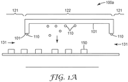
図1Aは、少なくとも1つの第1の領域121と少なくとも1つの第2の領域122との間の温度差によって結露液滴110が形成される表面101を含む処理施設100aの概念図である。例えば、第1の領域121は室温であってもよく、第2の領域122は、領域121の温度が領域122の温度よりも高いような冷蔵庫であってもよい。製品、例えば、食品150は、経路199に沿って、室温領域121から冷蔵領域122に、及び/又は冷蔵領域122の外に移動する。2つの領域121、122間の温度差により、結露110は、室温領域121と冷蔵領域122との間の開口部131及び冷蔵領域122の表面に形成される。最終的に、結露122は合体し、食品150上に滴下する。食品150への結露110の落下は、食料汚染の仕組みをなし、そうでなければ実質的な細菌増殖の懸念を引き起こさないであろう水分量の少ない食料の水分活性を高める媒介となる。このリスクのために、政府機関は、食品処理業者に施設全体にわたる結露の管理を要求する。
FIG. 1A is a conceptual diagram of a
食品処理施設内の架空面に形成される結露を管理するいくつかの手法が、従前に用いられてきた。従前の手法は、生産ラインを定期的に停止して冷蔵領域を除霜すること、延長ポールに取り付けられたモップヘッドなどの吸収性材料を使用して結露生成面を乾燥すること、及び/又は水切りへら若しくは圧縮空気を使用して結露を除去することを伴う。他の手法としては、冷気送込み及び放出エリアへの暖気の流れを最小化することを試みる高価な「空気ナイフ」システムを使用することが挙げられる。しかし、これらシステムの大部分は、人の介入を必要とし、結露を軽減するために生産を停止する必要があることがある。 Several techniques have traditionally been used to control the formation of dew on the fictitious surface of food processing facilities. Previous methods include periodically shutting down the production line to defrost the refrigerated area, using an absorbent material such as a mop head attached to an extension pole to dry the dew condensation surface, and / or Accompanied by removing condensation using a drain spatula or compressed air. Another approach is to use an expensive "air knife" system that attempts to minimize the flow of warm air to the cold air inlet and discharge areas. However, most of these systems require human intervention and may require production to be stopped to reduce condensation.
本明細書に開示される手法は、結露を食品から恒常的に離して経路付けるマニホールドと共に使用される可撓性フィルムを伴う、結露管理装置及びシステムを対象とする。本明細書に開示される手法は、生産を停止することなく、及び/又は結露を除去するために物理的なモップ作業若しくは乾燥技術を使用することなく、処理施設における結露を軽減するために使用することができる。 The techniques disclosed herein are intended for condensation control devices and systems with flexible films used with manifolds that route condensation constantly away from food. The techniques disclosed herein are used to reduce condensation in a treatment facility without stopping production and / or using physical mopping or drying techniques to remove condensation. can do.
図1Bは、本明細書に記載される結露管理システム180が設置された処理施設100bを示す。結露110は、結露生成面101に形成された結露110がフィルム181に落下するように、結露生成面101の下に懸架された1つ以上の可撓性フィルム181により、食品150への落下が阻止される。いくつかの実施形態によれば、結露管理システム180は、フィルム181に流体的に連結され、捕捉された結露110を食品150から離して経路付けるように構成された、少なくとも1つのマニホールド182を含む。装着具183が、可撓性フィルム181を結露生成面101に対して位置決めし保持する。
FIG. 1B shows a
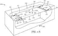
図2Aは、いくつかの実施形態による結露管理システム280を有する処理施設200の一部分の切断斜視図である。図2Bは、結露管理システム280の分解上面図である。システム280は、結露を収集し輸送するように構成され、親水性表面を含んでもよい流体制御フィルム210と、少なくとも1つのマニホールドと、装着具261とを含む。マニホールドは、傾斜したフィルム210の上面212及び下面211によって輸送される結露を収集し、例えば単一の放出箇所に、放出する。装着具261及びマニホールドは同時に、フィルム及び/又は他のシステム構造を冷たい表面から熱的に切り離すことによって凍結に対する感受性を低減することを可能にする、「浮いた」可撓性フィルムに張力を掛ける仕組みをもたらす。
FIG. 2A is a cut perspective view of a part of the
図2A及び図2Bは、第1の支持体221と第2の支持体222との間に配置された可撓性流体制御フィルム210を示す。支持体221、222の一方又は両方は、結露を収集し放出するマニホールドを備えてもよい。いくつかの実施形態において、可撓性流体制御フィルム210は、第1の側部271と、反対側の第2の側部272と、第3の側部273と、反対側の第4の側部274とを有する四辺形又は矩形であってもよい。可撓性フィルム281は、第1の側部271及び第2の側部272と交差する横方向軸線298と、第3の側部273及び第4の側部274と交差する長手方向軸線299とを有する。図2Bに示すように、フィルム210は、第1の側部271と第3の側部273との間の第1の角部281、第3の側部273と第2の側部272との間の第2の角部282、第2の側部272と第4の側部274との間の第3の角部283、及び第4の側部274と第1の側部271との間の第4の角部284を含んでもよい。図2Aに示すように、支持体221、222は、結露生成面201に形成された結露202が可撓性フィルム210の第2の表面212に落下するように、結露生成面201に対して可撓性フィルム210を位置決めし保持する。一部の結露は、可撓性フィルム210の反対側にある第1の表面211に形成されてもよい。
2A and 2B show the flexible
支持体221、222は、フィルム210の2つの反対側の側部273、274にそれぞれ取り付けられるように構成されている。いくつかの実施形態において、支持体221、222の両方は、フィルム210の第2の表面212に落下する結露202をマニホールド221、222内に経路付けるように、フィルム210に流体的に連結されるマニホールドである。いくつかの実施形態において、支持体221、222の一方が支持体としてのみ機能し、マニホールドの流体構造を含まないことが可能である。いくつかの実施形態において、両方の支持体221、222はマニホールドであり、流体構造を有するが、結露は、支持体221、222の一方のみが結露を収集するように経路付けられる。
The
破線の矢印291、292、293は、処理施設200の天井から落下する水滴202aの経路を示す。水滴202aは、液滴202aがフィルム210の第2の表面212に到達するまで、重力方向に沿って下向きに落下する291。フィルム210は、その長手方向軸線299に沿って重力方向下向きに傾斜する。フィルム表面212において、液滴202aは、他の液滴と合体し、液滴202aがマニホールド221に到達するまで、フィルム210の長手方向軸線299に概ね沿って流れる292ことができる。液滴202aはマニホールド221に入り、液滴202aがマニホールド221の出口ポート223を通って出るまで、フィルム210の横方向軸線298に概ね沿って流れる293。
Dashed
装着具261は、支持体221、222に機械的に連結される。装着具261は、結露生成面201に形成された結露202が、結露生成面201からフィルム210の第2の表面212に落下するように、結露生成面201に対して支持体221、222を位置合わせし保持するように構成され配置される。
The fitting 261 is mechanically connected to the
フィルムの一方の側部273に配置され、結露を収集するように構成された第1のマニホールド221と、フィルム210の別の側部274に配置され、支持体としてのみ機能し、実質的な量の結露を収集しない、第2のマニホールド222とを含む、結露管理システム280について検討する。装着具261は、第1のマニホールドに取り付けられたフィルム210の側部273が、第2のマニホールド222に取り付けられた反対側の側部274よりも重力方向に沿って低くなるように配置されてもよい。いくつかの実施形態において、装着具261は、可撓性フィルム210の1つの角部282が最も低い箇所となるように配置されてもよい。最も低い角部282は、例えば、排水管290に取り付けられる、マニホールド221の端部に取り付けられ、マニホールド221の排水を助長してもよい。いくつかの実施形態において、マニホールド221、222は、マニホールドの端部にねじ付き部分又は先細部分などの1つ以上の構造を含んでもよく、1つ以上の構造は、排水管290の接続を助長するように構成される。
A
いくつかの実施形態において、可撓性フィルム210の主表面211、212は、実質的に平滑であってもよい。いくつかの実施形態において、微細構造230、240が、可撓性フィルム210の第1の主面211及び第2の主面212の一方又は両方に配置される。微細構造230、240は、結露がマニホールド221に向かって移動するのを助長するように、及び/又は蒸発を助長するために結露を這い上がらせるように構成されたマイクロチャネルであってもよい。図2Bは、マイクロチャネル230の第1の組及び240マイクロチャネルの第2の組を示し、マイクロチャネル230、240は流体的に接続されてもよい。
In some embodiments, the
図2Bに示すように、マイクロチャネル230の長手方向軸線は線233に沿って位置し、チャネル240の長手方向軸線は線232に沿って位置する。チャネル240は、図2Bに示すように、チャネル240に対してチャネル角度231を成す。いくつかの実施形態において、マイクロチャネル230の長手方向軸線は、フィルムの長手方向軸線299と実質的に揃う。いくつかの実施形態において、マイクロチャネル240の少なくとも一部の角度231は、例えば、0度より大きいかつ約90度未満、又は0度より大きいかつ約60度未満であってもよい。いくつかの実施形態において、チャネル角度231は、約45度未満である。
As shown in FIG. 2B, the longitudinal axis of the
いくつかの実施形態によれば、マイクロチャネル230、240は、可撓性フィルム210に沿って長手方向に、及び/又は可撓性フィルム210を横切って横方向にチャネル230、240内の流体の毛管移動をもたらすように構成される。流体を横方向に這い上がらせる毛管作用は、流体の表面−体積比が大きくなり、かつより急速な蒸発が可能になるように、フィルム210にわたって流体を分散させる。チャネル断面、チャネル表面エネルギー、及び流体表面張力により、毛管力が決定される。
According to some embodiments, the
図3〜図5は、様々な実施形態による、マイクロチャネルを有する流体制御フィルムを示す断面図である。図3に示すように、隆起部320が、フィルム310の基部330aの上方にz軸に沿って上昇して、マイクロチャネル330を形成し、各チャネル330は、いずれの側にも図3のx軸であるチャネル長手方向軸線に沿って延びる隆起部320を有する。チャネル長手方向軸線は、フィルムの長手方向軸線に対して実質的に平行であるか、又は傾斜してもよい。図3において、隆起部320は、チャネル330の基部330aと実質的に垂直にz軸に沿って立ち上がって示される。代わりに、いくつかの実施形態において、隆起部は、チャネルの基部に対して垂直以外の角度で延びることができる。チャネル330の隆起部320は、チャネル330の基面330aから隆起部320の頂面320aまでで測定される高さhpを有する。隆起高さhpは、フィルム310に耐久性及び保護をもたらすように選択されてもよい。いくつかの実施形態において、隆起高さhpは、約25μm〜約1000μm、又は約100μm〜約200μmであり、チャネル断面幅wcは約25μm〜約1000μmであり、隆起部断面幅wrは約30μm〜約250μmである。
3-5 are cross-sectional views showing fluid control films having microchannels according to various embodiments. As shown in FIG. 3, the raised
いくつかの実施形態において、図3に示すように、チャネル330の側面320bは、チャネル330の基面330aにおける隆起部の幅が隆起部320の頂面320aにおける隆起部の幅よりも広くなるように、断面が傾斜してもよい。このケースにおいて、チャネル330の基部330aにおけるチャネル330の幅は、隆起部320の頂面320aにおけるチャネル330の幅よりも狭い。代わりに、チャネルの底面におけるチャネル幅が、隆起部の頂面におけるチャネル幅よりも広くなるように、チャネルの側面を傾斜させることができる。
In some embodiments, as shown in FIG. 3, the
チャネル330の基面330aとフィルム310の反対側の面310aとの間の距離tvは、液滴がフィルム310によって這い上がるが、依然として堅牢な構造を維持できるように選択することができる。いくつかの実施形態において、厚さtvは、厚さ約75μm未満、約50μm未満、又は厚さ約20μm〜約200μmである。いくつかの実施形態において、親水性の表面構造又はコーティング350が、いくつかの実施形態において、基部330a、チャネル側部320b、及びチャネル頂部320aに配置され、例えば、コーティング又はプラズマ蒸着されてもよい。いくつかの実施形態において、隣り合う隆起部320の各組は、等しく離間している。他の実施形態において、隣り合う隆起部320の間隔は、少なくとも2つの異なる距離だけ離れていてもよい。
Distance t v between the
図4は、例示的な実施形態による、一次及び二次チャネル430、431を有する可撓性フィルム410の断面図である。一次及び二次チャネル430、431は、一次及び二次隆起部420、421によって画定される。チャネル430、431及び隆起部420、421は、図4のx軸であるチャネル長手方向軸線に沿って延びる。チャネル長手方向軸線は、フィルムの長手方向軸線に対して実質的に平行であるか、又は傾斜してもよい。各一次チャネル430は、一次チャネル430のいずれの側にもある一組の(第1及び第2の)一次隆起部420によって画定される。一次隆起部420は、チャネル430の基面430aから隆起部420の頂面420aまでで測定される高さhpを有する。
FIG. 4 is a cross-sectional view of a
いくつかの実施形態において、微細構造が一次チャネル430内に配置される。微細構造は、一次チャネル430の第1及び二次一次隆起部420間に配置された二次チャネル431を備えてもよい。二次チャネル431はそれぞれ、少なくとも1つの二次隆起部421と関連付けられる。二次チャネル431は、一組の二次隆起部421間、又は二次隆起部421と一次隆起部420との間に位置してもよい。
In some embodiments, the microstructure is placed within the
一次隆起部間の中心間距離dprは、約25μm〜約1000μmの範囲であってもよく、一次隆起部と最も近い二次隆起部との間の中心間距離dpsは、約5μm〜約350μmの範囲であってもよく、2つの二次隆起部間の中心間距離dssは、約5μm〜約350μmの範囲であってもよい。場合によっては、一次及び/又は二次隆起部は、基部からの距離と共に先細になってもよい。基部における一次隆起部の外面間の距離dpbは、約15μm〜約250μmの範囲であってもよく、約1μm〜約25μmの範囲のより小さな距離dptまで先細になってもよい。基部における二次隆起部の外面間の距離dsbは、約15μm〜約250μmの範囲であってもよく、約1μm〜約25μmの範囲のより小さな距離dstまで先細になってもよい。一例において、dpp=0.00898インチ(228μm)、dps=0.00264インチ(67μm)、dss=0.00185インチ(47μm)、dpb=0.00251インチ(64μm)、dpt=0.00100インチ(25.4μm)、dsb=0.00131インチ(33.3μm)、dst=0.00100インチ(25.4μm)、hp=0.00784インチ(200μm)、hs=0.00160インチ(40.6μm)である。 Center distance d pr between the primary ridges may range from about 25μm~ about 1000 .mu.m, center distance d ps between the nearest secondary ridges and the primary ridges, about 5μm~ about may be in the range of 350 .mu.m, the distance between the centers d ss between two secondary ridges may range from about 5μm~ about 350 .mu.m. In some cases, the primary and / or secondary ridges may taper with distance from the base. The distance d pb between the outer surface of the primary ridges at the base may be in the range of about 15μm~ about 250 [mu] m, it may be tapered to a smaller distance d pt in the range of about 1μm~ about 25 [mu] m. The distance d sb between the outer surfaces of the secondary ridges at the base may be in the range of about 15 μm to about 250 μm or may be tapered to a smaller distance d st in the range of about 1 μm to about 25 μm. In one example, d pp = 0.00898 inches (228μm), d ps = 0.00264 inches (67μm), d ss = 0.00185 inches (47μm), d pb = 0.00251 inches (64μm), d pt = 0.00100 inches (25.4μm), d sb = 0.00131 inch (33.3μm), d st = 0.00100 inch (25.4μm), h p = 0.00784 inch (200μm), h s = It is 0.00160 inches (40.6 μm).
二次隆起部421は、チャネル430の基面430aから二次隆起部421の頂面421aまでで測定される高さhsを有する。一次隆起部420の高さhpは、二次隆起部421の高さhsより大きくてもよい。いくつかの実施形態において、一次隆起部の高さは、約25μm〜約1000μm、又は約100μm〜約200μmであり、二次隆起部の高さは、約5μm〜約350μm、又は約20μm〜約50μmである。いくつかの実施形態において、二次隆起部421の高さhsと一次隆起部420の高さhpとの比は、約1:5である。いくつかの実施形態において、hsはhpの半分未満である。一次隆起部420は、フィルム410の耐久性と、二次チャネル431、二次隆起部、及び/又は一次隆起部420間に配置された他の微細構造の保護とをもたらすように設計することができる。可撓性フィルム410は、流体の蒸発を助長するために、フィルム410の表面にわたって流体を分散させるように構成されてもよい。
The secondary ridge 421 has a height h s measured from the
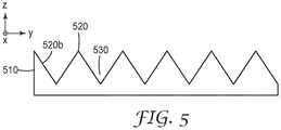
図5は、例示的な実施形態による、隆起部520及びチャネル530を有する結露制御フィルム510の断面図を示す。チャネル530は、チャネル530を画定する隆起部520によってV字形状とされる。この実施形態において、チャネル530の側面520bは、層表面と垂直な軸線、すなわち図5のz軸に対して、例えば、20度、40度、または40度などの0度より大きいかつ90度未満のある角度で配置される。前述したように、フィルム510のチャネル530及び隆起部520は、フィルム510の長手方向軸線に対して実質的に平行であるか、又は傾斜するチャネル軸線に沿って位置してもよい。隆起部520は、いくつかの実施形態において互いに等しい距離だけ離れていてもよい。
FIG. 5 shows a cross-sectional view of a dew
本明細書に記載されるチャネルは、フィルムの一方又は両方の主面に沿って延びる開放した個々の毛管チャネルの連なりを形成する所定のパターンで複製されてもよい。シート又はフィルムに形成されたこれらの微細複製チャネルは、実質的に各チャネルの長さに沿って、例えばチャネルごとに、全体に一様かつ規則的である。フィルム又はシートは、薄く、可撓性であり、製造の費用対効率が高くてもよく、その意図される用途に望ましい材料特性を有するように形成することができる。 The channels described herein may be replicated in a predetermined pattern forming a chain of open individual capillary channels extending along one or both main surfaces of the film. These microreplicating channels formed on the sheet or film are uniform and regular throughout, substantially along the length of each channel, eg, channel by channel. The film or sheet may be thin, flexible, cost-effective to manufacture, and can be formed to have desirable material properties for its intended use.
本明細書において述べた可撓性フィルムは、毛管作用によってチャネルに沿って流体を自発的に輸送することが可能であってもよい。流体制御フィルムが流体を自発的に輸送する能力に影響を及ぼす2つの一般的な要因は、(i)表面の幾何学形状又はトポグラフィ(毛管現象、チャネルのサイズ及び形状)、並びに(ii)フィルム表面の性質(例えば表面エネルギー)である。所望の量の流体輸送能力を達成するために、設計者は、流体制御フィルムの構造若しくはトポグラフィを調節してもよく、及び/又は流体制御フィルムの表面の表面エネルギーを調節してもよい。毛管作用による自発的な這い上がりによって流体輸送を行うようチャネルが機能するために、チャネルは一般に、流体と流体制御フィルムの表面との間の接触角度が90度以下で流体がチャネルの表面を濡らすことを可能にするのに十分な程度に親水性である。 The flexible films described herein may be capable of spontaneously transporting fluid along the channel by capillary action. Two common factors that affect the ability of a fluid control film to transport fluid spontaneously are (i) surface geometry or topography (capillary action, channel size and shape), and (ii) film. Surface properties (eg, surface energy). To achieve the desired amount of fluid transport capacity, the designer may adjust the structure or topography of the fluid control film and / or adjust the surface energy of the surface of the fluid control film. In order for the channel to function to transport the fluid by spontaneous crawling due to capillary action, the channel generally wets the surface of the channel at a contact angle of 90 degrees or less between the fluid and the surface of the fluid control film. It is hydrophilic enough to make this possible.
いくつかの実装形態において、本明細書に記載した流体制御フィルムは、連続的な及び/又はロールツーロール式のフィルム製作を可能にする押出エンボス加工工程を用いて準備することができる。1つの好適な工程によれば、流動性材料が、成形ツールの成形表面と連続的に線接触させられる。成形ツールは、ツールの表面に切削されたエンボス加工パターンを有し、このエンボス加工パターンは、ネガの浮き彫りとなっている流体制御フィルムのマイクロチャネルパターンである。成形ツールによって流動性材料に複数のマイクロチャネルが形成される。流動性材料は固化して、長手方向軸線に沿った長さ及び幅を有する細長い流体制御フィルムを形成し、長さは幅よりも大きい。マイクロチャネルは、フィルムの長手方向軸線に対して0度より大きいかつ90度未満の角度を成すチャネル長手方向軸線に沿って形成することができる。いくつかの実施形態において、角度は、例えば45度未満である。 In some embodiments, the fluid control films described herein can be prepared using an extrusion embossing process that allows continuous and / or roll-to-roll film production. According to one preferred step, the fluid material is in continuous line contact with the molding surface of the molding tool. The forming tool has an embossed pattern cut on the surface of the tool, which is the microchannel pattern of the fluid control film that is the relief of the negative. The forming tool forms multiple microchannels in the fluid material. The fluid material solidifies to form an elongated fluid control film having a length and width along the longitudinal axis, the length being greater than the width. Microchannels can be formed along the channel longitudinal axis at an angle greater than 0 degrees and less than 90 degrees with respect to the longitudinal axis of the film. In some embodiments, the angle is, for example, less than 45 degrees.
流動性材料は、流動性材料が成形ツールの表面と線接触させられるように、ダイから成形ツールの表面上に直接押し出してもよい。流動性材料は、例えば、様々な光硬化性、熱硬化性、及び熱可塑性の樹脂組成物を含んでいてもよい。線接触は樹脂の上流縁部によって画定され、成形ツールが回転するにつれ、成形ツール及び流動性材料の両方に対して移動する。得られた流体制御フィルムは、ロール製品の形態の物品を産出するようにロールに巻き取ることができる単一層の物品であってもよい。いくつかの実装形態において、製作工程は、マイクロチャネルを有する流体制御フィルムの表面処理、例えば、本明細書に開示するような親水性コーティングのプラズマ蒸着を更に含んでもよい。いくつかの実装形態では、成形ツールは、ロール又はベルトであってよく、反対側にあるローラとともにニップを形成する。成形ツールと反対側にあるローラとの間のニップは、流動性材料を成形パターン内へと押し込むのを補助する。ニップを形成する間隙の間隔は、所定の厚さの流体制御フィルムの形成を補助するように調節することができる。開示する流体制御フィルムに好適な製作工程についての追加の情報は、同一出願人による米国特許第6,375,871号及び第6,372,323号に記載されており、これらの各々は、そのそれぞれの全体が、参照により本明細書に組み込まれている。 The fluid material may be extruded directly from the die onto the surface of the molding tool so that the fluid material is in line contact with the surface of the molding tool. The fluid material may include, for example, various photocurable, thermosetting, and thermoplastic resin compositions. Line contact is defined by the upstream edge of the resin and moves with respect to both the forming tool and the fluid material as the forming tool rotates. The resulting fluid control film may be a single layer article that can be wound onto a roll to produce an article in the form of a roll product. In some implementations, the fabrication process may further include surface treatment of fluid control films with microchannels, such as plasma deposition of hydrophilic coatings as disclosed herein. In some implementations, the forming tool may be a roll or belt, forming a nip with a roller on the opposite side. A nip between the molding tool and the roller on the opposite side assists in pushing the fluid material into the molding pattern. The spacing between the gaps forming the nip can be adjusted to aid in the formation of a fluid control film of a given thickness. Additional information about the manufacturing process suitable for the disclosed fluid control films is described in US Pat. Nos. 6,375,871 and 6,372,323 by the same applicant, each of which is said. Each in its entirety is incorporated herein by reference.
本明細書において述べる流体制御フィルムは、例えば、ポリエチレン、ポリプロピレン、ポリエステル、コポリエステル、ポリウレタン、ポリオレフィン、ポリアミド、ポリ(塩化ビニル)、ポリエーテルエステル、ポリイミド、ポリエステルアミド、ポリアクリレート、ポリ酢酸ビニル、ポリ酢酸ビニルの加水分解誘導体などを含む、鋳造又はエンボス加工に好適な任意のポリマー材料から形成することができる。特定の実施形態は、ポリオレフィン、特にポリエチレン又はポリプロピレン、それらのブレンド及び/又はコポリマー、並びにプロピレン及び/又はエチレンと、酢酸ビニル又はアクリル酸メチルやブチルなどのアクリレートなどの他の少量のモノマーとのコポリマーを使用する。ポリオレフィンは、鋳造用ロール又はエンボス加工用ロールの表面を容易に複製する。これらは丈夫で耐久性があり、それらの形状を良好に保持するので、鋳造又はエンボス加工工程後のそのようなフィルムの取り扱いが容易になる。親水性ポリウレタンは、物理特性及び本来的に高い表面エネルギーを有する。代わりに、流体制御フィルムは、熱硬化性物質(硬化性樹脂材料)、例えばポリウレタン、アクリレート、エポキシ及びシリコーンから鋳造することができ、暴露放射(例えば熱、UV、又はEビーム放射、等)又は水分によって硬化させることができる。これらの材料は、表面エネルギー改変剤(例えば界面活性剤及び親水性ポリマー)、可塑剤、抗酸化剤、顔料、剥離剤、静電気防止剤などを含む、様々な添加剤を含有してもよい。いくつかの場合において、チャネルは無機材料(例えば、ガラス、セラミックス、又は金属)を使用して形成され得る。 The fluid control film described herein includes, for example, polyethylene, polypropylene, polyester, copolyester, polyurethane, polyolefin, polyamide, poly (vinyl chloride), polyether ester, polyimide, polyesteramide, polyacrylate, polyvinyl acetate, poly. It can be formed from any polymeric material suitable for casting or embossing, including hydrolyzed derivatives of vinyl acetate and the like. Certain embodiments include polyolefins, especially polyethylene or polypropylene, blends and / or copolymers thereof, and copolymers of propylene and / or ethylene with other small amounts of monomers such as vinyl acetate or acrylates such as methyl acrylate and butyl. To use. Polyolefins easily duplicate the surface of casting rolls or embossing rolls. They are durable and durable and retain their shape well, facilitating the handling of such films after casting or embossing steps. Hydrophilic polyurethane has physical characteristics and inherently high surface energy. Alternatively, the fluid control film can be cast from thermosetting materials (curable resin materials) such as polyurethane, acrylates, epoxies and silicones and exposed radiation (eg heat, UV, or E-beam radiation, etc.) or It can be cured by moisture. These materials may contain various additives, including surface energy modifiers (eg surfactants and hydrophilic polymers), plasticizers, antioxidants, pigments, release agents, antistatic agents and the like. In some cases, the channel can be formed using an inorganic material (eg, glass, ceramics, or metal).
流体制御フィルムの好適な剛性は、インチ幅当り約100ポンドの力〜インチ幅当り約1500ポンドの力の範囲であってもよい。いくつかの実施形態によれば、横方向の剛性は、長手方向の剛性よりも低くてもよい。 Suitable stiffness of the fluid control film may range from a force of about 100 pounds per inch width to a force of about 1500 pounds per inch width. According to some embodiments, the lateral stiffness may be lower than the longitudinal stiffness.
いくつかの実施形態において、流体制御フィルムは、特性変更添加剤又は表面コーティングを含んでよい。添加剤の例としては、難燃剤、疎水剤、親水剤、抗菌剤、無機物、腐食抑制剤、金属粒子、ガラス繊維、充填剤、粘土、及びナノ粒子が挙げられる。十分な毛管力が保証されるように、フィルム表面を変性させてよい。例えば、表面が十分な親水性を有することが保証されるように表面を変性させてよい。フィルムは一般に、フィルム表面が親水性となって水性流体と90°以下の接触角度、より好ましくは45°以下の接触角度を呈するように、(例えば表面処理、表面コーティング若しくは薬剤の適用、又は選択された薬剤の組み込みによって)変性させてよい。いくつかの実施形態によれば、可撓性フィルムは、プラズマ強化化学蒸着(PECVD)によって堆積された有機シランを含む親水性コーティングを一方又は両方のフィルム表面に含む。 In some embodiments, the fluid control film may include a property-altering additive or surface coating. Examples of additives include flame retardants, hydrophobic agents, hydrophilic agents, antibacterial agents, inorganic substances, corrosion inhibitors, metal particles, glass fibers, fillers, clays, and nanoparticles. The film surface may be denatured to ensure sufficient capillary strength. For example, the surface may be modified to ensure that the surface has sufficient hydrophilicity. Films are generally such that the film surface becomes hydrophilic and exhibits a contact angle of 90 ° or less, more preferably 45 ° or less with an aqueous fluid (eg, surface treatment, surface coating or chemical application, or selection). It may be denatured (by incorporating the drug). According to some embodiments, the flexible film comprises a hydrophilic coating containing organic silane deposited by plasma-enhanced chemical vapor deposition (PECVD) on one or both film surfaces.
本発明の流体制御フィルムに親水性の表面を実現するために、任意の好適な既知の方法を利用してよい。界面活性剤の局所適用、プラズマ処理、真空蒸着、親水性モノマーの重合、フィルム表面への親水性成分のグラフト化、コロナ処理又は火炎処理などの表面処理を用いてもよい。代わりに、界面活性剤又は他の好適な薬剤が、フィルム押出時に内部特性変更添加剤として樹脂とブレンドされてもよい。典型的には、界面活性剤コーティングの局所適用に依存するよりはむしろ、流体制御フィルムの原料となるポリマー組成物内に、界面活性剤が組み込まれる。この理由は、局所適用されたコーティングはチャネルの切欠きを埋めてしまう(すなわち鋭さを損なう)傾向を有する場合があり、このことにより、本発明が対象とする所望の流体の流れと干渉するからである。コーティングが施されるとき、これは、構造化表面の一様な薄い層を助長するために、全体に薄い。ポリエチレン流体制御フィルムに組み込み可能な界面活性剤の例示的な例は、例えば約0.1〜0.5重量パーセントで用いられる、オクチルフェノキシポリエトキシエタノール非イオン性界面活性剤である、TRITON(商標)X−100(コネチカット州DanburyのUnion Carbide Corp.から入手可能)である。 Any suitable known method may be utilized to achieve a hydrophilic surface on the fluid control film of the present invention. Surface treatments such as topical application of surfactants, plasma treatment, vacuum deposition, polymerization of hydrophilic monomers, grafting of hydrophilic components onto the film surface, corona treatment or flame treatment may be used. Alternatively, a surfactant or other suitable agent may be blended with the resin as an internal property changing additive during film extrusion. Typically, the surfactant is incorporated within the polymer composition that is the source of the fluid control film, rather than relying on topical application of the surfactant coating. The reason for this is that topically applied coatings may tend to fill the notches in the channel (ie, impair sharpness), which interferes with the desired fluid flow of interest in the present invention. Is. When the coating is applied, it is thin overall to facilitate a uniform thin layer of the structured surface. An exemplary example of a surfactant that can be incorporated into a polyethylene fluid control film is octylphenoxypolyethoxyethanol nonionic surfactant, used, for example, at about 0.1 to 0.5 weight percent, TRITON ™. ) X-100 (available from Union Carbide Corp. in Danbury, Connecticut).
本発明の建築構造用途に関する高い耐久性要件に好適な他の界面活性剤材料には、Polystep(登録商標)B22(イリノイ州NorthfieldのStepan Companyから入手可能)、及びTRITON(商標)X−35(コネチカット州DanburyのUnion Carbide Corp.から入手可能)が挙げられる。 Other surfactant materials suitable for the high durability requirements for building structural applications of the present invention include Polystep® B22 (available from Stepan Company, Northfield, Connecticut), and TRITON ™ X-35 (Trademark). (Available from Union Carbide Corp. in Danbury, Connecticut).
流体制御フィルムの特性を調節するために、界面活性剤又は複数の界面活性剤の混合物を、流体制御フィルムの表面に適用してよいか、又は、フィルムに含浸させてよい。例えば、流体制御フィルムの表面の親水性を、そのような成分を有さない場合のフィルムよりも高めることが望まれる場合がある。 To adjust the properties of the fluid control film, a surfactant or a mixture of surfactants may be applied to the surface of the fluid control film or impregnated into the film. For example, it may be desired to increase the hydrophilicity of the surface of the fluid control film as compared to the film without such a component.
親水性ポリマー又はポリマーの混合物のような界面活性剤は、流体制御フィルムの特性を調節するために、流体制御フィルムの表面に適用するか、又はフィルムに含浸させてもよい。代わりに、フィルムに親水性モノマーを添加し、その場で重合させて、相互貫入ポリマーネットワークを形成させてもよい。例えば、親水性アクリレート及び開始剤を添加し、熱又は化学線によって重合させることができる。 Surfactants, such as hydrophilic polymers or mixtures of polymers, may be applied to the surface of the fluid control film or impregnated into the film in order to adjust the properties of the fluid control film. Alternatively, hydrophilic monomers may be added to the film and polymerized in situ to form a cross-intrusive polymer network. For example, hydrophilic acrylates and initiators can be added and polymerized by heat or chemical lines.
好適な親水性ポリマーとしては、エチレン酸化物のホモ及びコポリマー、ビニルピロリドン、カルボン酸、スルホン酸、又はアクリル酸などのホスホン酸官能性アクリレートなどのビニル不飽和モノマーを組み込む親水性ポリマー、ヒドロキシエチルアクリレート、酢酸ビニル及びその加水分解誘導体(例えばポリビニルアルコール)、アクリルアミド、ポリエトキシル化アクリレートなどのヒドロキシ官能性アクリレート;親水性改質セルロース、並びにデンプン及び改質デンプン、デキストランなどの多糖類などが挙げられる。 Suitable hydrophilic polymers include homo and copolymers of ethylene oxide, hydrophilic polymers incorporating vinyl unsaturated monomers such as vinylpyrrolidone, carboxylic acids, sulfonic acids, or phosphonic acid functional acrylates such as acrylic acid, hydroxyethyl acrylates. , Vinyl acetate and its hydrolyzed derivatives (eg, polyvinyl alcohol), hydroxyfunctional acrylates such as acrylamide, polyethoxylated acrylates; hydrophilic modified celluloses, and polysaccharides such as starches and modified starches, dextrans and the like.
上述したように、流体制御フィルムの特性を調節するために、親水性シラン又は複数のシランの混合物を、流体制御フィルムの表面に適用するか、又はフィルムに含浸させてもよい。好適なシランとしては、米国特許第5,585,186号に開示されているアニオン性シラン、及び非イオン性又は陽イオン性の親水性シランが挙げられる。 As mentioned above, hydrophilic silanes or mixtures of silanes may be applied to the surface of the fluid control film or impregnated into the film in order to adjust the properties of the fluid control film. Suitable silanes include anionic silanes disclosed in US Pat. No. 5,585,186 and nonionic or cationic hydrophilic silanes.
本明細書において述べるマイクロチャネル流体制御フィルムに好適な材料に関する追加の情報は、参照により本明細書に組み込まれている、同一出願人による米国特許公開第2005/0106360号に記載されている。 Additional information regarding suitable materials for the microchannel fluid control films described herein is described in US Patent Publication No. 2005/01036360 by the same applicant, which is incorporated herein by reference.
いくつかの実施形態において、親水性コーティングを、プラズマ蒸着によって流体制御フィルムの表面に堆積させることができ、これはバッチ式の工程又は連続的な工程において行われてよい。本明細書で使用される場合、”プラズマ”という用語は、電子、イオン、中性分子、遊離基、並びに他の励起状態の原子及び分子を含めた反応種を含有する、部分的にイオン化された気体又は流体状態の物質を意味する。 In some embodiments, the hydrophilic coating can be deposited on the surface of the fluid control film by plasma deposition, which may be done in batch or continuous steps. As used herein, the term "plasma" is partially ionized and contains reactive species including electrons, ions, neutral molecules, free radicals, and other excited atoms and molecules. It means a substance in a gas or fluid state.
概して、プラズマ蒸着は、1つ以上の気体状シリコン含有化合物を充填した(大気圧に対して)圧力を下げたチャンバを通して、流体制御フィルムを移動させることを含む。フィルムに隣接して又は接触して位置する電極に電力が供給される。このことにより電界が形成され、この電界が、気体状シリコン含有化合物から、シリコンを多く含んだプラズマを形成する。 In general, plasma deposition involves moving a fluid control film through a reduced pressure chamber filled with one or more gaseous silicon-containing compounds (relative to atmospheric pressure). Power is supplied to the electrodes located adjacent to or in contact with the film. As a result, an electric field is formed, and this electric field forms a silicon-rich plasma from the gaseous silicon-containing compound.
次いでプラズマによりイオン化された分子が、電極に向かって加速され、流体制御フィルムの表面に衝突する。この衝突のおかげで、イオン化された分子は、親水性コーティングを形成する表面と反応し、共有結合する。親水性コーティングをプラズマ蒸着するための温度は、比較的低い(例えば約摂氏10度)。代替の蒸着技法(例えば化学気相成長)に必要とされる高い温度が、多層フィルム12に好適な多くの材料、例えばポリイミドを劣化させることが知られているため、これは有益である。 The molecules ionized by the plasma are then accelerated towards the electrodes and collide with the surface of the fluid control film. Thanks to this collision, the ionized molecules react and covalently bond with the surface forming the hydrophilic coating. The temperature for plasma deposition of the hydrophilic coating is relatively low (eg about 10 degrees Celsius). This is beneficial because the high temperatures required for alternative vapor deposition techniques (eg, chemical vapor deposition) are known to degrade many materials suitable for multilayer films 12, such as polyimide.
プラズマ蒸着の程度は、気体状シリコン含有化合物の組成、他の気体の存在、プラズマへの流体制御フィルムの表面の曝露時間、電極に供給される電力のレベル、気体流量、及び反応チャンバ圧などの、様々な処理要因によって決まり得る。これらの要因はそれぞれ相応に、親水性コーティングの厚さを決定するのに寄与する。 The degree of plasma deposition includes the composition of gaseous silicon-containing compounds, the presence of other gases, the exposure time of the surface of the fluid control film to plasma, the level of power delivered to the electrodes, the gas flow rate, and the reaction chamber pressure. , Can be determined by various processing factors. Each of these factors contributes accordingly to determining the thickness of the hydrophilic coating.
親水性のコーティングには、1つ以上のシリコン含有材料、例えば、シリコン/酸素材料、ダイヤモンド状ガラス(DLG)材料、及びこれらの組み合わせが挙げられる。シリコン/酸素材料の層を堆積させるのに好適な気体状シリコン含有化合物の例には、シラン(例えばSiH4)が挙げられる。DLG材料の層を堆積させるのに好適な気体状シリコン含有化合物の例には、反応チャンバ56の圧力が低いときに気体状態である、気体状有機シリコン化合物が挙げられる。好適な有機シリコン化合物の例には、トリメチルシラン、トリエチルシラン、トリメトキシシラン、トリエトキシシラン、テトラメチルシラン、テトラエチルシラン、テトラメトキシシラン、テトラエトキシシラン、ヘキサメチルシクロトリシロキサン、テトラメチルシクロテトラシロキサン、テトラエチルシクロテトラシロキサン、オクタメチルシクロテトラシロキサン、ヘキサメチルジシロキサン、ビストリメチルシリルメタン、及びこれらの組み合わせが挙げられる。特に好適な有機シリコン化合物の例には、テトラメチルシランが挙げられる。 Hydrophilic coatings include one or more silicon-containing materials such as silicon / oxygen materials, diamond-like glass (DLG) materials, and combinations thereof. Examples of gaseous silicon-containing compounds suitable for depositing layers of silicon / oxygen material include silanes (eg SiH4). Examples of gaseous silicon-containing compounds suitable for depositing layers of DLG material include gaseous organic silicon compounds, which are in a gaseous state when the pressure in the reaction chamber 56 is low. Examples of suitable organic silicon compounds include trimethylsilane, triethylsilane, trimethoxysilane, triethoxysilane, tetramethylsilane, tetraethylsilane, tetramethoxysilane, tetraethoxysilane, hexamethylcyclotrisiloxane, and tetramethylcyclotetrasiloxane. , Tetraethylcyclotetrasiloxane, octamethylcyclotetrasiloxane, hexamethyldisiloxane, bistrimethylsilylmethane, and combinations thereof. Examples of particularly suitable organic silicone compounds include tetramethylsilane.
気体状シリコン含有化合物を用いたプラズマ蒸着工程の完了後、気体状無機化合物は、堆積した材料から表面のメチル基を除去するためのプラズマ処理のために引き続き用いられてよい。これにより、結果的な親水性コーティングの親水特性が高まる。 After completion of the plasma deposition step with the gaseous silicon-containing compound, the gaseous inorganic compound may continue to be used for plasma treatment to remove surface methyl groups from the deposited material. This enhances the hydrophilic properties of the resulting hydrophilic coating.
本開示において述べるような流体制御フィルムに親水性コーティングを施すための材料及び工程に関する追加の情報は、参照により本明細書に組み込まれている、同一出願人による米国特許公開第2007/0139451号に記載されている。 Additional information regarding materials and processes for applying hydrophilic coatings to fluid control films as described herein can be found in US Patent Publication No. 2007/0139451 by the same Applicant, incorporated herein by reference. Has been described.
図6A〜図6Dは、マニホールド600の様々な図をより詳細に示す。図6Aは、第1の細長チャネル611を備える第1の部分610と、第2の細長チャネル621を備える第2の部分620とを含む、マニホールド600の分解図である。第1及び第2のチャネル611、621はそれぞれ、マニホールド600の長手方向軸線699に沿って実質的に直線であってもよい。第2の部分620は、図6Bに示すマニホールド600の斜視図に示すように、第1の部分610の第1の細長チャネル611内に入れ子にされるように構成される。
6A-6D show various views of the manifold 600 in more detail. FIG. 6A is an exploded view of the manifold 600 including a
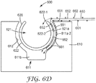
図6Cの斜視図及び図6Dの端面図で最も良く分かるように、マニホールド600は、第1の部分610と第2の部分620が入れ子にされ一緒になるときに、第1の部分610と第2の部分620との間で可撓性流体制御フィルム650を把持するように構成される。第1及び第2の部分610、620が入れ子にされ一緒になるときに、可撓性フィルム650の第1の表面651は、第1のチャネル611に流体的に連結され、結露管理フィルム650の反対側の第2の表面652は、第2のチャネル621に流体的に連結される。第2の部分620が第1の細長チャネル611内に入れ子にされるときに、第2の部分620の外面622及び第1の部分610の内面612は、可撓性フィルム650をマニホールド600に取り付ける摩擦クランプをもたらす。いくつかの実施形態によれば、入れ子にされた第1及び第2の部分610、620によって形成される摩擦クランプは、約100マイクロメートル〜約1000マイクロメートルの厚さを有する可撓性フィルム650をクランプするように構成される。いくつかのケースにおいて、フィルム又はマニホールドの部分を実質的に損傷させることなく、第2の部分620を第1の部分610から取り外し、フィルム650をマニホールド600の摩擦グリップから自由にできるように、摩擦クランプは可逆性である。
As best seen in the perspective view of FIG. 6C and the end view of FIG. 6D, the manifold 600 has a
図6Aで最も良く分かるように、断面で見ると、第1の細長チャネル611は、第2のチャネルが内部に入れ子にされたときに摩擦クランプをもたらすように構成された第1のセクション611aと、第1の長手方向結露流路を形成する第2のセクション611bとを含む。断面で見ると、第1のセクション611aは、流路611bによって互いに隔てられた2つの湾曲した側部611a−1、611a−2を含む。例えば、2つの湾曲した側部611a−1、611a−2はそれぞれ、円の一部分の形状を有してもよい。図6Aに示すように、断面において、第2の細長チャネル621は湾曲しており、不完全な円を形成してもよい。第2の細長チャネル621は、第2の結露流路を形成する。いくつかの実施形態によれば、マニホールド600の第1の細長チャネル611の内面と第2の部分620の外面との間に配置された任意選択的な1つ以上の排水溝671、672が存在してもよい。1つ以上の排水溝671、672は、フィルム650からの結露(図6D及び図6Dを参照)が第1の細長チャネル611に入ることを可能にするように構成される。例えば、いくつかの実施形態において、排水溝671は、第1の細長チャネル611の湾曲部分611a−2に形成されてもよい。いくつかの実施形態において、任意選択的な排水溝672は、第2の部分620の外面に形成されてもよい。
As best seen in FIG. 6A, in cross section, the first
図6Dは、液滴がマニホールド600の流路611、621内に移動するときの水の液滴の経路を示す。液滴662は、可撓性フィルム650の第2の表面652に形成され又は第2の表面に落下し、重力及び/又は毛管作用の影響によってマニホールド600に向けて移動する。第2の表面652に形成された又は第2の表面に落下した液滴の一部662−1は、フィルム650に沿って、マニホールド650の第2のチャネル621内に移動する。第2の表面652に形成された又は第2の表面に落下した液滴の一部662−2は、フィルム650の第2の表面652とマニホールド650の第2の部分620の外面621aとの間でマイクロチャネル内を移動し、第1の部分610の流路611b内に入ってもよい。
FIG. 6D shows the path of a water droplet as it travels into the
フィルム650の第1の表面651に形成された液滴661は、重力及び/又は毛管作用の影響によってマニホールド600に向けて移動する。液滴661は、フィルム650の第1の表面651とマニホールドの第1の部分610の湾曲した側部611a−2との間で第1の表面651のマイクロチャネル内を移動し、最終的に第1のマニホールド部分610の流路611b内に入る。
The
マニホールド600は、任意の適切な長さであり得る。例えば、マニホールドは、約5インチ〜約36インチであってもよい。いくつかの実施形態において、チャネル611、621は、チャネル611、621がマニホールド600と実質的に同じ長さとなるように、マニホールド600の一端部から他端部まで延在してもよい。したがって、チャネル611、621もそれぞれ、約5インチ〜約36インチの長さを有してもよい。第1の細長チャネル611の湾曲した側部611a−1、611a−2間の好適な最大内側幅は、例えば、約4ミリメートル〜約20ミリメートル、又は約10ミリメートルである。第2の細長チャネル621の好適な最大内側幅は、例えば、約4ミリメートル〜約16ミリメートル、又は約8mmであってもよい。
The manifold 600 can be of any suitable length. For example, the manifold may be from about 5 inches to about 36 inches. In some embodiments, the
図7は、いくつかの実施形態による、フィルム750に取り付けられたマニホールド700の端部領域の斜視図を示す。マニホールド700は、第1の結露流路711bを含む第1のチャネル711を有する第1の部分710を含む。マニホールド700は、第2の結露流路721を備える第2の部分720と、第1及び第2のチャネル711、721と実質的に平行な第3の結露流路730とを含む。
FIG. 7 shows a perspective view of the end region of the manifold 700 attached to the
液滴762は、可撓性フィルム750の第2の表面752に形成され、又は第2の表面に落下し、重力及び/又は毛管作用の影響によってマニホールド700に向けて移動する。第2の表面752に形成された又は第2の表面に落下した液滴の一部762−1は、フィルム750に沿って移動し、マニホールド750の第2チャネル721内に落下する。第2の表面752に形成された又は第2の表面を落下した液滴の一部762−2は、フィルム750の第2の表面752とマニホールド750の第2の部分720の外面721aとの間のマイクロチャネル内を移動し、マニホールド700の第1の部分710の流路711b内に入ってもよい。
The
フィルム750の第1の表面751に形成された液滴761は、重力及び/又は毛管作用の影響によってマニホールド700に向けて移動する。第3の流路730に落下する液滴の一部761−1。液滴の一部761−2は、第1の表面751のマイクロチャネル内を移動し続け、最終的にフィルム750の第1の表面751とマニホールド700の第1の部分710の湾曲した側部711a−2との間を流れ、最終的に第1のマニホールド部分710の流路711bに流入する。
The
図8は、互いに対して回転できるように取り付けられた第1の部分810及び第2の部分820を含むマニホールド800の斜視図を示す。第1の部分810は、第1の端部801及び第2の端部811を有する。第2の部分820は、第1の端部802及び第2の端部821を有する。多くの点で、図8のマニホールド800は、図6A〜図6Dに示したマニホールド600又は図7のマニホールド700と同様であり得る。マニホールド800は、マニホールド800の第1及び第2の部分810、820が、第2の部分820が、図8に示すy軸である横方向軸線の周りで第1の部分810に対して回転できるように、第1及び第2の部分810、820の第1の端部801、802において、例えば、ピボット又はヒンジ830によって互いに取り付けられる点で異なる。第2の部分820は、第2の部分820が第1の部分のチャネル805内に入れ子にされるまで、ピボット830の周りを回転することができる。
FIG. 8 shows a perspective view of the manifold 800 including the
図9A及び図9Bは、(図9A及び図9Bに示していない)可撓性フィルムを把持するマニホールド950(又はフィルム支持体)に連結するように構成された装着具900の正面斜視図及び背面斜視図である。装着具及びマニホールドは同時に、マニホールド及び/又はフィルムを冷たい表面から熱的に切り離すことによってマニホールド及び/又はフィルムを凍結し難くすることを可能にする、「浮いた」材料に張力を掛ける仕組みをもたらす。 9A and 9B are front perspective views and back views of a fitting 900 configured to connect to a manifold 950 (or film support) that grips a flexible film (not shown in FIGS. 9A and 9B). It is a perspective view. The fittings and manifolds at the same time provide a mechanism for tensioning the "floating" material, which makes it difficult to freeze the manifold and / or film by thermally separating the manifold and / or film from the cold surface. ..
装着具900は、結露生成面に形成された結露が可撓性フィルムの表面に落下するように結露生成面に対して可撓性フィルムを位置決めし保持するために、例えば壁、天井、又は他の構造体などの構造体に取り付けられてもよい。図9A及び図9Bに示すように、装着具900は、ベース部分910、中間部分920、及び取付部分930を含んでもよい。ベース部分910は、例えば、壁、天井、又は他の構造体などの構造体に取り付けることができる。例えば、ベース部分910は、締結具、例えば、釘、ねじ、リベット、フックなどによって、摩擦コネクタによって、接着剤によって、溶接、ろう付け、若しくははんだ付けによって、又は任意の他の好適な手段によって、構造体に恒久的に又は取り外し可能に取り付けられてもよい。取付部分930は、図10及び図11に示すように、マニホールド950に取り付けるか、又はフィルムに直接取り付けるように構成された取付要素931を有する。例えば、取付要素931は、図9A及び図9Bに示すようなフックを備えてもよく、又は別の好適な取付要素を備えてもよい。
The fitting 900 is used, for example, on a wall, ceiling, or the like to position and hold the flexible film with respect to the dew formation surface so that the dew formed on the dew formation surface falls on the surface of the flexible film. It may be attached to a structure such as the structure of. As shown in FIGS. 9A and 9B, the fitting 900 may include a
中間部分920は、取付部分930とベース部分910との間に配置される。いくつかの実施形態によれば、中間部分920は、ばね又は弾性ストラップ又はバンジーなどの弾性部品921を備えてもよい。弾性部品921は、可撓性フィルムに張力を付与するように構成される。図9A及び図9Bに示すように、中間部分920の弾性部分921は、ベース部分の穴912を通って挿入されたボルト又はロッド911に取り付けられ、1つ以上のナット913によって固定されてもよい。
The
装着具900の構造は、マニホールド950とベース部分910が装着される構造体との間の熱的な切り離しを助長し得る。例えば、いくつかの実施形態によれば、部分910、920、930のうちの1つ以上が、ゴム、プラスチック、若しくはナイロンなどの断熱材であるか又はそれを含む場合に、熱的な切り離しを向上させ得る。いくつかの実施形態において、絶縁体材料が、例えば、ベース部分910とベース部分が上部に装着される構造体との間に挿入されてもよい。加えて又は代わりに、熱絶縁体をベース部分910と中間部分920との間、及び/又は中間部分920と取付部分930との間に挿入することができる。
The structure of the fitting 900 may facilitate thermal separation between the manifold 950 and the structure to which the
加えて又は代わりに、ベース部分910と中間部分920との間、及び/又は中間部分920と取付部分930との間の接合部のうちの1つ以上、並びに/又は装着具の別の場所が、部分910、920、930間に小さな断面の接続領域を有することによって、熱的な結合を制限してもよい。1つ以上の小さな断面の接続領域は、構造体をマニホールド950から熱的に切り離す機能を果すことができる。図9A及び図9Bは、取付部分930の穴932に挿入された中間部分920のばね端部922を備える、中間部分920と取付部分との間の小さな断面の接続領域を示す。
In addition or instead, one or more of the joints between the
いくつかの実施形態において、図9A及び図9Bに示した装着具900と同様の装着具が、マニホールドが使用されないケースであっても、可撓性流体制御フィルムを結露生成面に対して位置決めするのに有用であり得る。図10及び図11から理解できるように、いくつかの実施態様において、装着具をフィルム1000に直接連結することができる。図10は、平らにされた可撓性フィルム1000を示す。他の形状が可能であるが、図示の実施形態において、可撓性フィルム1000は細長い台形である。フィルム1000は、第1の端部1011と、反対側の第2の端部1012と、第1の端部1011から第2の端部1012まで延びる第1の側部1021と、第1の端部1011と第2の端部1210との間に延びる第2の側部1022とを有する。図10に示す実施形態において、第1の端部1011におけるフィルム1000の幅は、第2の端部1012におけるフィルム100の幅よりも小さい。第1及び第2の端部1011、1012は実質的に平行であり、第1及び第2の側部1021、1022は平行でない。フィルム1000の各角部1032に近接して配置された取付構造1031が存在する。図10に示すように、いくつかの実施態様において、取付構造1031は、フィルム100を通る穴であるが、他の種類の取付構造を用いることもできる。
In some embodiments, a fitting similar to the fitting 900 shown in FIGS. 9A and 9B positions the flexible fluid control film with respect to the condensation formation surface, even in cases where the manifold is not used. Can be useful for. As can be seen from FIGS. 10 and 11, in some embodiments, the fixture can be directly attached to the
図11は、図10に示した可撓性フィルム1000を含む結露管理システム1100を示す。可撓性フィルム1000は、可撓性フィルム1000の端部1011、1012に連結された1つ以上の装着具1110によって位置決めされ保持される。装着具1110は、可撓性フィルム1000が第1の側部1021と第2の側部1022との間で横方向に湾曲するように、可撓性フィルム1000を結露生成面1150に対して保持するように配置される。装着具は、図9A及び図9Bに示した装着具と同様とすることができる。図11に見られるように、装着具1110は、フィルムの穴など、フィルム1000の角部に配置された取付構造1031に直接連結されてもよい。例えば、図9Aに示したような装着具900の取付要素931は、装着具のベース部分910がドアフレームなどの構造体又は他の構造体に取り付けられた状態で、フィルム内の4つの孔1031のそれぞれに挿入されてもよい。
FIG. 11 shows a
装着されると、可撓性フィルム1000は、凹面及び反対側の凸面1000aを有する。可撓性フィルム1000は、結露生成面1050に形成された結露がフィルム1000の凹面1000aに落下するように、装着具1110によって表面1150に対して位置決めされ保持される。いくつかの実施形態によれば、前述のマイクロチャネル1050a、1050bは、フィルムの凹面及び凸面の一方又は両方に配置される。フィルムの長手方向軸線1099と実質的に平行な長手方向軸線を有するマイクロチャネル1050aにより、フィルムの最も低い端部の排水部に向かってフィルムに沿って結露を移動させることが助長され得る。フィルムの長手方向軸線1099に対して傾斜した長手方向軸線を有するマイクロチャネル1050bは、重力に反してチャネル内の結露を這い上がらせることによって結露を広げるのに有用であり得る。結露を広げることにより、結露の乾燥がより速く助長される。いくつかのケースにおいて、前述したように、凹状及び/又は凸状のフィルム表面は、親水性の層又は表面構造を有してもよい。
When mounted, the
湾曲フィルム1000の底部1030は、重力方向に沿った垂直軸線に沿って、第1の端部1011から第2の端部1012まで下向きに傾斜する。図11に示すように位置決めされたフィルムの所定の勾配はA/Bであり、ここで、Aは、フィルムの底部が垂直に下がる距離であり、Bは、水平軸線に沿ったフィルムの長さである。フィルム1000の勾配は、結露生成構造体のサイズ及び形状に依存し得る。図11に示すように、結露管理システム1100は、ドアのヘッダ部分に形成される結露を管理するように位置決めされる。長手方向の毛管チャネル1050aを有するフィルムは、長手方向チャネルを有していないフィルムよりもはるかに小さな勾配で液体を輸送することができる。したがって、長手方向の毛管チャネル1050aを有するフィルムは、長手方向チャネルを有していないフィルムまたは傾斜付きチャネルのみを有するフィルムよりも小さな勾配を有するように配置されてもよい。いくつかの実施形態において、フィルムの勾配A/Bは、約0.01〜約0.2の範囲内であってもよい。
The
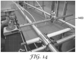
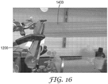
可撓性フィルムに張力を掛け、図12〜図17の様々な図に示すように2つのマニホールド間である勾配に保持した。図12は、制御された実験を行うために使用した試験装置の側面図を示す。図13は、フィルムに張力を掛け、結露を収集し、フィルムの頂部及び底部のマイクロチャネルによって輸送された結露を放出するために使用したマニホールド1200の底部及び側部の拡大図を示す。図14は、フィルム1400の頂部を見下す試験装置の図を示す。図15及び図16は、マニホールド1200に取り付けられたフィルム1400を示す、マニホールド1200の上面図及び側面図を示す。図17は、フィルム1400の底面図である。図12〜図17に示すように、マニホールドは、ジグによって保持され、勾配を変化させるために位置決めし直すことができた。制御された分注速度で液滴をフィルムの上面に滴下して、結露生成面から落下する結露をシミュレートした。噴霧器を使用して、フィルムの底面に結露液滴を生成した。結露をマニホールド内に輸送し、単一の収集箇所から放出した。フィルム及びマニホールドによって収集された結露の量を計量した。
The flexible film was tensioned and held in a gradient between the two manifolds as shown in the various figures of FIGS. 12-17. FIG. 12 shows a side view of the test equipment used to perform a controlled experiment. FIG. 13 shows an enlarged view of the bottom and sides of the manifold 1200 used to tension the film, collect condensation, and release the condensation transported by the microchannels at the top and bottom of the film. FIG. 14 shows a diagram of a test device looking down at the top of
実施例1:収集された結露の質量、及びマニホールドに到達する前に裏面の結露が滴下した角度を、様々な勾配にある張力を掛けられた毛細管フィルムで試験した。表1に提示するデータは、0度に向けられたチャネルを有する親水性毛管フィルムにより、マニホールドに到達する前に結露が落ちることなく、裏面の結露を−3度の勾配で930mm輸送できることを示す。しかし、−1.7度の勾配では、マニホールドに到達する前に、同じフィルムにより結露が落ちる(滴下する)。

実施例2:様々な材料を評価して、マニホールドに到達する前の滴下前に、材料が−1.3度の勾配で裏面の結露をどの程度遠くまで輸送できるかを決定した。表2は結果を要約する。
Cerex Advanced Fabrics製のNylon 6,6 PAスパンボンド/化学ボンド 68gsmの親水性材料を、湿らせて距離(94cm)にわたって伸長させ、(中間点で6cm)弛ませたときに、定常状態の滴下が観察された低いスポットを形成した。したがって、水との接触及び弛みが生じたときに膨潤又は伸張する材料は、結露をマニホールド装置に輸送することができない。 Steady-state dripping when a hydrophilic material of Nylon 6,6 PA spunbond / chemical bond 68 gsm from Cerex Advanced Fabrics was moistened and stretched over a distance (94 cm) and loosened (6 cm at the midpoint). Formed the observed low spots. Therefore, a material that swells or stretches when it comes into contact with water and loosens cannot transport condensation to the manifold device.
Fiberweb製のStyle# T0505 PPスパンボンド/メルトブロー/スパンボンド 15.6gsmの疎水性不織布では、水が輸送されず、定常状態の滴下が直ちに観察された。本実施例により、このシステムにおける親水性毛管材料の必要性が示される。 In the Fiberweb Style # T0505 PP spunbond / melt blow / spunbond 15.6 gsm hydrophobic non-woven fabric, water was not transported and steady-state dripping was immediately observed. This example demonstrates the need for hydrophilic capillary materials in this system.
American Nonwoven製のStyle RB−316−28−G/R、25%PET/75%梳毛調レーヨン/レジンボンド 33.5gsmの不織布では、5FPMの設定流量で輸送するのに十分な毛管力が認められず、エアゾール化された水が試料に接触した場所で定常状態の滴下が直ちに観察された。 American Nonwoven Style RB-316-28-G / R, 25% PET / 75% worsted rayon / resin bond 33.5 gsm non-woven fabric has sufficient capillary strength to transport at a set flow rate of 5 FPM. Instead, steady-state dripping was immediately observed where the aerosolized water came into contact with the sample.
実施例3:比較例は、疎水性の平坦フィルムが収集及び輸送に利用されると、どのようになるかを示す。図18は、疎水性の平坦フィルムが使用されるとき、液体の「フィンガリング」(矢印1801によって示す)が、散発的であり、マニホールドに到達する前に水をフィルムの縁部に落下させ得る(故障の仕組みである)ことを示す。更なる貯留(矢印1802によって示す)により、材料の弛みが作り出されることがあり、マニホールドの前で液体が落ちることもある。 Example 3: Comparative Examples show what happens when a hydrophobic flat film is used for collection and transport. FIG. 18 shows that when a hydrophobic flat film is used, the liquid "fingering" (indicated by arrow 1801) is sporadic and water can be dropped onto the edges of the film before reaching the manifold. (It is a mechanism of failure). Further retention (indicated by arrow 1802) may create slack in the material and may cause the liquid to fall in front of the manifold.
本明細書に開示された実施形態は、下記を含む。 The embodiments disclosed herein include:
実施形態1. 第1の結露流路を備える第1の細長チャネルを含む第1の部分と、
第2の結露流路を備える第2の細長チャネルを含む第2の部分であって、可撓性結露管理フィルムの第1の表面が第1の流路に流体的に連結され、かつ結露管理フィルムの反対側の第2の表面が第2の流路に流体的に連結されるように、第1の部分内に少なくとも部分的に入れ子になるように構成された第2の部分と
を備える結露管理マニホールド。
A second portion comprising a second elongated channel comprising a second dew condensation channel, wherein the first surface of the flexible dew control film is fluidly coupled to the first channel and dew condensation control. It comprises a second portion configured to be at least partially nested within the first portion such that the second surface on the opposite side of the film is fluidly connected to the second flow path. Condensation control manifold.
実施形態2. 第2の部分が第1の部分の第1の細長チャネル内に入れ子にされるときに、第2の部分及び第1の細長チャネルは、可撓性結露管理フィルムの端部をマニホールドに取り付ける摩擦クランプをもたらす、実施形態1に記載のマニホールド。
実施形態3. 摩擦クランプは、約50マイクロメートル〜約1000マイクロメートルの厚さを有する可撓性結露管理フィルムをクランプするように構成されている、実施形態2に記載のマニホールド。
Embodiment 3. The manifold according to
実施形態4. 摩擦クランプは、フィルム又はマニホールドを実質的に損傷させることなく、結露管理フィルムがマニホールドに取り付けられ、その後にマニホールドから取り外されることを可能にする可逆的な摩擦クランプである、実施形態2に記載のマニホールド。
Embodiment 4. 22. The friction clamp is described in
実施形態5. 断面において、第1の細長チャネルは、摩擦クランプをもたらすように構成された第1のセクションと、第1の結露流路を形成する第2のセクションとを含む、実施形態2に記載のマニホールド。
Embodiment 5. The manifold according to
実施形態6. 断面において、第1の細長チャネルの第1のセクションは、第1の流路によって隔てられた2つの湾曲した側部を含む、実施形態2に記載のマニホールド。
Embodiment 6. The manifold according to
実施形態7. 2つの湾曲した側部はそれぞれ、円の一部分を含む、実施形態6に記載のマニホールド。 Embodiment 7. The manifold according to embodiment 6, wherein each of the two curved sides comprises a portion of a circle.
実施形態8. 断面において、第2の細長チャネルは、不完全な円である、実施形態1〜7のいずれかに記載のマニホールド。 Embodiment 8. The manifold according to any of embodiments 1-7, wherein the second elongated channel is an incomplete circle in cross section.
実施形態9. マニホールドの第1の部分と第2の部分との間に1つ以上の排水溝を更に備え、1つ以上の排水溝は、フィルムからの結露が第1の結露流路に入ることを可能にするように構成されている、実施形態1〜8のいずれかに記載のマニホールド。 Embodiment 9. Further provided with one or more drains between the first and second parts of the manifold, the one or more drains allow condensation from the film to enter the first condensation channel. The manifold according to any one of embodiments 1-8, which is configured to:
実施形態10. 排水溝は、第1の細長チャネルの内面に配置されている、実施形態9に記載のマニホールド。 Embodiment 10. The manifold according to embodiment 9, wherein the drainage ditch is arranged on the inner surface of the first elongated channel.
実施形態11. 排水溝は、第1の部分内に入れ子になる第2の部分の外面に配置されている、実施形態9に記載のマニホールド。 Embodiment 11. The manifold according to embodiment 9, wherein the drainage ditch is arranged on the outer surface of a second portion nested within the first portion.
実施形態12. 第1の部分の長さ及び第2の部分の長さが、約5インチ〜約36インチである、実施形態1〜11のいずれかに記載のマニホールド。 Embodiment 12. The manifold according to any of embodiments 1-11, wherein the length of the first portion and the length of the second portion are from about 5 inches to about 36 inches.
実施形態13. 第1の細長チャネルの最大内側幅が、約4ミリメートル〜約20ミリメートルである、実施形態1〜12のいずれかに記載のマニホールド。 Embodiment 13. The manifold according to any of embodiments 1-12, wherein the first elongated channel has a maximum inner width of about 4 mm to about 20 mm.
実施形態14. 第2の細長チャネルの最大内側幅が、約4ミリメートル〜約16ミリメートルである、実施形態1〜13のいずれかに記載のマニホールド。 Embodiment 14. The manifold according to any of embodiments 1-13, wherein the second elongated channel has a maximum inner width of about 4 mm to about 16 mm.
実施形態15. 第1の部分は、第1の端部及び第2の端部を含み、第1の細長チャネルは、第1の部分の第1の端部と第2の端部との間に配置されており、
第2の部分は、第1の端部及び第2の端部を含み、第2の細長チャネルは、第2の部分の第1の端部と第2の端部との間に配置されており、
第1の部分及び第2の部分は、第1の部分の第1の端部及び第2の部分の第1の端部のヒンジによって取り付けられて一緒になっている、実施形態1〜14のいずれかに記載のマニホールド。
Embodiment 15. The first portion includes a first end and a second end, and the first elongated channel is arranged between the first end and the second end of the first part. Ori
The second portion includes a first end and a second end, and a second elongated channel is arranged between the first end and the second end of the second part. Ori
Embodiments 1-14, wherein the first portion and the second portion are attached and together by a hinge at the first end of the first portion and the first end of the second portion. Manifold described in either.
実施形態16. 第1及び第2のチャネルはそれぞれ、マニホールドの長手方向軸線に沿って実質的に直線である、実施形態1〜15のいずれかに記載のマニホールド。 Embodiment 16. The manifold according to any of embodiments 1-15, wherein the first and second channels are substantially straight along the longitudinal axis of the manifold, respectively.
実施形態17. 第1の部分は、可撓性結露管理フィルムの第1の表面に流体的に連結された第3の結露流路を含む、実施形態1〜16のいずれかに記載のマニホールド。 Embodiment 17. The manifold according to any one of embodiments 1-16, wherein the first portion comprises a third condensation flow path fluidly coupled to a first surface of the flexible condensation control film.
実施形態18. 結露管理マニホールドと、
結露管理フィルム支持体と、
マニホールドと支持体との間に配置された可撓性結露管理フィルムとを備え、結露マニホールドは、
第1の結露流路を備える第1の細長チャネルを含む第1の部分と、
第2の結露流路を備える第2の細長チャネルを含む第2の部分であって、フィルムの第1の表面が第1のチャネルに流体的に連結され、かつフィルムの反対側の第2の表面が第2のチャネルに流体的に連結されるように、第1の細長チャネル内に入れ子になるように構成された第2の部分と
を備える、結露管理システム。
Embodiment 18. Condensation control manifold and
Condensation control film support and
A flexible dew condensation control film placed between the manifold and the support is provided, and the dew condensation manifold is
A first portion containing a first elongated channel with a first dew condensation channel,
A second portion comprising a second elongated channel comprising a second condensation channel, wherein the first surface of the film is fluidly coupled to the first channel and the second on the opposite side of the film. A dew condensation management system comprising a second portion configured to be nested within a first elongated channel such that the surface is fluidly coupled to the second channel.
実施形態19. 結露管理フィルム支持体は、第2の結露管理マニホールドを備える、実施形態18に記載のシステム。 Embodiment 19. The system according to embodiment 18, wherein the condensation control film support comprises a second condensation control manifold.
実施形態20. 可撓性結露管理フィルムは、フィルムの第1の表面及び第2の表面の一方又は両方に配置されたマイクロチャネルを含む、実施形態18〜19のいずれかに記載のシステム。 20. The system according to any of embodiments 18-19, wherein the flexible condensation control film comprises microchannels located on one or both of the first and second surfaces of the film.
実施形態21. 可撓性結露管理フィルムのチャネルは、重力に逆らって結露を這い上がらせるように構成された毛管チャネルである、実施形態20に記載のシステム。 21. Embodiment 21. 20. The system of embodiment 20, wherein the channel of the flexible dew control film is a capillary channel configured to crawl up dew against gravity.
実施形態22. フィルムは、支持体からマニホールドに向かって下向きに傾斜している、実施形態18〜21のいずれかに記載のシステム。 Embodiment 22. The system according to any of embodiments 18-21, wherein the film is tilted downward from the support towards the manifold.
実施形態23. 結露管理フィルムの一方又は両方の表面に配置された親水性層又は親水性表面構造を更に備える、実施形態18に記載のシステム。 23. 18. The system of embodiment 18, further comprising a hydrophilic layer or hydrophilic surface structure disposed on one or both surfaces of the condensation control film.
実施形態24. マニホールドに機械的に連結された少なくとも1つの装着具を更に備え、装着具は、結露生成面に形成された結露が結露生成面からフィルムの表面に落下するように、結露生成面に対してマニホールドを位置決めし保持するように構成されている、実施形態18〜23のいずれかに記載のシステム。
実施形態25. 装着具は、マニホールドを結露生成面から熱的に切り離している、実施形態24に記載のシステム。
Embodiment 25. The system according to
実施形態26. 装着具は、ばねによってマニホールドに機械的に連結されている、実施形態24に記載のシステム。
Embodiment 26. 24. The system of
実施形態27. マニホールドは、第1の端部及び第2の端部を備え、第1及び第2の長手方向チャネルは、第1の端部と第2の端部との間に配置されており、
システムは、
マニホールドの第1の端部に機械的に連結された第1の装着具と、
マニホールドの第2の端部に機械的に連結された第2の装着具とを更に備え、第1及び第2の装着具は、結露生成面に形成された結露が結露生成面からフィルムの第1の表面に落下するように、結露生成面に対してマニホールドを位置決めし保持するように構成されている、実施形態18〜26のいずれかに記載のシステム。
Embodiment 27. The manifold comprises a first end and a second end, and the first and second longitudinal channels are located between the first end and the second end.
the system,
A first fitting mechanically connected to the first end of the manifold,
A second mounting tool mechanically connected to the second end of the manifold is further provided, and the first and second mounting tools are such that the dew condensation formed on the dew condensation forming surface is formed on the dew condensation forming surface to form a film. The system according to any one of embodiments 18 to 26, wherein the manifold is configured to position and hold with respect to the dew condensation forming surface so as to fall onto the surface of 1.
実施形態28. マニホールドの第1の端部は、第1の弾性要素によって第1の装着具に機械的に連結されており、
マニホールドの第2の端部は、第2の弾性要素によって第2の装着具に機械的に連結されている、実施形態27に記載のシステム。
Embodiment 28. The first end of the manifold is mechanically connected to the first fitting by a first elastic element.
28. The system of embodiment 27, wherein the second end of the manifold is mechanically connected to a second fitting by a second elastic element.
実施形態29. 複数の取付構造を有する台形の可撓性結露管理フィルムと、
可撓性結露管理フィルムの複数の取付構造にそれぞれ連結された複数の装着具であって、フィルムがフィルムの横方向軸線に沿って湾曲し、かつ湾曲した結露管理フィルムの底部が重力方向に沿って下向きに傾斜するように、フィルムを結露生成面に対して位置決めし保持するように構成されている、複数の装着具と
を備える結露管理システム。
Embodiment 29. A trapezoidal flexible dew condensation control film with multiple mounting structures,
Multiple mounting tools, each connected to multiple mounting structures of the flexible condensation control film, where the film is curved along the lateral axis of the film and the bottom of the curved condensation control film is along the direction of gravity. A condensation management system with multiple fittings configured to position and hold the film against the condensation formation surface so that it tilts downwards.
実施形態30. 湾曲した結露管理フィルムの側部が、重力方向に対して実質的に垂直に向けられている、実施形態29に記載のシステム。 30. 29. The system of embodiment 29, wherein the sides of the curved condensation control film are oriented substantially perpendicular to the direction of gravity.
実施形態31. 各装着具は、結露管理フィルムの取付構造に連結するように構成された取付要素を含み、
装着具の取付要素はフックであり、
フィルムの取付構造は、結露管理フィルムの孔である、実施形態29〜30のいずれかに記載のシステム。
Embodiment 31. Each fixture includes mounting elements configured to connect to the mounting structure of the condensation control film.
The mounting element of the fixture is a hook,
The system according to any one of embodiments 29 to 30, wherein the film mounting structure is a hole in the condensation control film.
実施形態32. 各装着具は、ベース部分と、ベース部分と取付構造との間に配置された弾性要素とを含む、実施形態31に記載のシステム。 Embodiment 32. 31. The system of embodiment 31, wherein each fitting comprises a base portion and an elastic element disposed between the base portion and the mounting structure.
実施形態33. 結露管理フィルムは毛管マイクロチャネルを含む、実施形態29〜32のいずれかに記載のシステム。 Embodiment 33. The system according to any of embodiments 29-32, wherein the condensation control film comprises capillary microchannels.
実施形態34. 結露管理フィルムの一方又は両方の表面に配置された親水性層又は親水性表面構造を更に備える、実施形態29〜33のいずれかに記載のシステム。 Embodiment 34. The system according to any of embodiments 29-33, further comprising a hydrophilic layer or a hydrophilic surface structure disposed on one or both surfaces of the condensation control film.
別途断りがない限り、本明細書及び特許請求の範囲で用いる加工寸法(feature size)、量、及び物理的特性を表す全ての数は、全ての場合において、用語「約」によって修飾されていると理解するものとする。したがって、特に反対の指示のない限り、上記明細書及び添付の特許請求の範囲に記載されている数値パラメータは、本明細書で開示される教示を利用して当業者が得ようとする所望の特性に応じて変動し得る近似値である。端点による数値範囲の使用は、その範囲内の全ての数(例えば、1〜5は、1、1.5、2、2.75、3、3.80、4、及び5を含む)、及びその範囲内の任意の範囲を含む。 Unless otherwise noted, all numbers representing the feature size, quantity, and physical properties used herein and in the claims are in all cases modified by the term "about". It shall be understood. Accordingly, unless otherwise indicated, the numerical parameters described in the specification and the appended claims are desired to be obtained by those skilled in the art using the teachings disclosed herein. It is an approximate value that can vary depending on the characteristics. The use of numerical ranges by endpoints is for all numbers within that range (eg, 1-5 includes 1, 1.5, 2, 2.75, 3, 3.80, 4, and 5), and Includes any range within that range.
これら実施形態の様々な修正及び変更が、当業者には明らかとなるものであり、本開示の本範囲は、本明細書に記載されている例示的実施形態に限定されるものではないことを理解されたい。例えば、1つの開示実施形態の特徴は、別途指示のない限り、他の開示実施形態全てにも適用され得ることを、読者は前提とすべきである。 Various modifications and changes to these embodiments will be apparent to those of skill in the art, and the scope of this disclosure is not limited to the exemplary embodiments described herein. I want to be understood. For example, the reader should assume that the characteristics of one disclosure embodiment can be applied to all other disclosure embodiments, unless otherwise indicated.
Claims (9)
第1の結露流路を備える第1の細長チャネルを含む第1の部分と、
第2の結露流路を備える第2の細長チャネルを含む第2の部分であって、可撓性結露管理フィルムの第1の表面が前記第1の結露流路に流体的に連結され、かつ前記可撓性結露管理フィルムの反対側の第2の表面が前記第2の結露流路に流体的に連結されるように、前記第1の部分内に少なくとも部分的に入れ子になるように構成された第2の部分と、
を備え、
前記第2の部分が前記第1の部分の前記第1の細長チャネル内に入れ子にされるときに、前記第2の部分及び前記第1の細長チャネルは、前記可撓性結露管理フィルムの端部を前記結露管理マニホールドに取り付ける摩擦クランプをもたらす、結露管理マニホールド。 It is a condensation control manifold,
A first portion containing a first elongated channel with a first dew condensation channel,
A second portion comprising a second elongated channel comprising a second condensation channel, wherein the first surface of the flexible condensation control film is fluidly coupled to the first condensation channel and The second surface on the opposite side of the flexible condensation control film is configured to be at least partially nested within the first portion so as to be fluidly connected to the second condensation flow path. a second portion,
Equipped with
When the second portion is nested within the first elongated channel of the first portion, the second portion and the first elongated channel are at the edges of the flexible condensation control film. A condensation control manifold that provides a friction clamp that attaches a portion to the condensation control manifold .
Applications Claiming Priority (3)
| Application Number | Priority Date | Filing Date | Title |
|---|---|---|---|
| US201662436801P | 2016-12-20 | 2016-12-20 | |
| US62/436,801 | 2016-12-20 | ||
| PCT/IB2017/058072 WO2018116133A1 (en) | 2016-12-20 | 2017-12-18 | Condensate management manifold and system |
Publications (3)
| Publication Number | Publication Date |
|---|---|
| JP2020507050A JP2020507050A (en) | 2020-03-05 |
| JP2020507050A5 JP2020507050A5 (en) | 2021-02-12 |
| JP6983253B2 true JP6983253B2 (en) | 2021-12-17 |
Family
ID=62626087
Family Applications (1)
| Application Number | Title | Priority Date | Filing Date |
|---|---|---|---|
| JP2019554045A Active JP6983253B2 (en) | 2016-12-20 | 2017-12-18 | Condensation control manifold and system |
Country Status (5)
| Country | Link |
|---|---|
| US (1) | US11079136B2 (en) |
| EP (1) | EP3557976A4 (en) |
| JP (1) | JP6983253B2 (en) |
| CN (1) | CN110087453B (en) |
| WO (1) | WO2018116133A1 (en) |
Families Citing this family (3)
| Publication number | Priority date | Publication date | Assignee | Title |
|---|---|---|---|---|
| JP6994507B2 (en) | 2016-12-05 | 2022-01-14 | スリーエム イノベイティブ プロパティズ カンパニー | Dew condensation management system |
| US11326807B2 (en) | 2019-05-31 | 2022-05-10 | Carrier Corporation | Condensate receptor for vertical mounted v-coil heat exchanger |
| CN114308976A (en) * | 2021-12-09 | 2022-04-12 | 中建三局集团有限公司 | Special-shaped foundation pit dustproof canopy and installation and use method thereof |
Family Cites Families (39)
| Publication number | Priority date | Publication date | Assignee | Title |
|---|---|---|---|---|
| JP2567693B2 (en) * | 1989-03-06 | 1996-12-25 | 三洋電機株式会社 | High humidity low temperature storage |
| US5197238A (en) * | 1989-06-15 | 1993-03-30 | Alexander Peleg | Enclosed structures |
| ATE94156T1 (en) | 1989-11-03 | 1993-09-15 | Hoppe & Partner | MUD DRAINING DEVICE. |
| NL9201005A (en) | 1991-06-07 | 1992-11-02 | Bom P L J Beheer Bv | DEPARTMENT HOUSE AND Gutter edge profile for this. |
| US5514120A (en) | 1991-12-18 | 1996-05-07 | Minnesota Mining And Manufacturing Company | Liquid management member for absorbent articles |
| NL9300966A (en) | 1992-06-05 | 1994-01-03 | Bom P L J Beheer Bv | Greenhouse, construction system and channel section therefor |
| US5728446A (en) | 1993-08-22 | 1998-03-17 | Johnston; Raymond P. | Liquid management film for absorbent articles |
| US5585186A (en) | 1994-12-12 | 1996-12-17 | Minnesota Mining And Manufacturing Company | Coating composition having anti-reflective, and anti-fogging properties |
| US6375871B1 (en) | 1998-06-18 | 2002-04-23 | 3M Innovative Properties Company | Methods of manufacturing microfluidic articles |
| US6420622B1 (en) | 1997-08-01 | 2002-07-16 | 3M Innovative Properties Company | Medical article having fluid control film |
| US6372323B1 (en) | 1998-10-05 | 2002-04-16 | 3M Innovative Properties Company | Slip control article for wet and dry applications |
| NL1010438C2 (en) | 1998-10-30 | 2000-08-17 | Rolloos Soerensen B V | Building with gutter, as well as gutter for application therein. |
| NL1012483C2 (en) | 1999-04-27 | 2000-10-30 | Bordeso Bv | Gutter in gully of greenhouse roof has thermal insulation under rainwater channel to restrict condensation |
| US6531206B2 (en) | 2001-02-07 | 2003-03-11 | 3M Innovative Properties Company | Microstructured surface film assembly for liquid acquisition and transport |
| DE10126467A1 (en) * | 2001-05-31 | 2003-01-02 | Norddeutsche Affinerie | Device for holding heating elements |
| US6803090B2 (en) | 2002-05-13 | 2004-10-12 | 3M Innovative Properties Company | Fluid transport assemblies with flame retardant properties |
| US20050106360A1 (en) * | 2003-11-13 | 2005-05-19 | Johnston Raymond P. | Microstructured surface building assemblies for fluid disposition |
| JP4739740B2 (en) * | 2003-12-26 | 2011-08-03 | Agcグリーンテック株式会社 | Resin film coated building |
| EP1547460B1 (en) * | 2003-12-26 | 2008-12-03 | AGC Green-Tec Co., Ltd. | Building covered with resin films |
| JP5004263B2 (en) | 2004-07-16 | 2012-08-22 | 渡辺パイプ株式会社 | Multiple building type weatherproof greenhouse |
| US20070003443A1 (en) * | 2005-06-23 | 2007-01-04 | Applera Corporation | Thermal-cycling pipette tip |
| US20070139451A1 (en) | 2005-12-20 | 2007-06-21 | Somasiri Nanayakkara L | Microfluidic device having hydrophilic microchannels |
| US7418827B2 (en) * | 2006-01-20 | 2008-09-02 | Carrier Corporation | Vertical condensate pan with non-modifying slope attachment to horizontal pan for multi-poise furnace coils |
| US7878019B2 (en) * | 2006-06-30 | 2011-02-01 | Christopher Ralph Cantolino | One-piece float switch housing and drain line assembly with condensate collection pan |
| JP4899681B2 (en) * | 2006-07-18 | 2012-03-21 | 富士ゼロックス株式会社 | Microchannel device |
| US20120023709A1 (en) | 2006-12-28 | 2012-02-02 | Hsu Wei K | Reusable, autoclaveable closure device for a flexible bag |
| NL1034948C2 (en) | 2008-01-24 | 2009-07-27 | Bordeso Bv | Greenhouse, has gutter comprising second profile for rainwater drainage and third profile above it for roof inspection walkway or window washing device transport rail |
| SE533393C2 (en) | 2008-02-15 | 2010-09-14 | Eaz Pac Ab | Flexible housing for food containers |
| US8431671B2 (en) | 2008-03-26 | 2013-04-30 | 3M Innovative Properties Company | Structured polydiorganosiloxane polyamide containing devices and methods |
| FR2929353B1 (en) | 2008-04-01 | 2010-04-02 | Opaly | DEVICE FOR FASTENING A FLEXIBLE TABLE. |
| US8769979B2 (en) * | 2008-04-03 | 2014-07-08 | Lennox Manufacturing, Inc. | Apparatus and method for draining condensate |
| JP5514493B2 (en) | 2009-09-02 | 2014-06-04 | 東都興業株式会社 | Condensed water recovery device that also serves as a sheet fixing |
| WO2011032164A2 (en) * | 2009-09-14 | 2011-03-17 | Kmetovicz Ronald E | Solar heat pipe heat exchanger |
| FR2974971B1 (en) | 2011-05-13 | 2013-06-14 | Filclair | DEVICE FOR EXHAUSTING WATER CONDENSED FROM THE INTERIOR SURFACE OF THE COVERING FILM OF A GREENHOUSE |
| US9777962B2 (en) * | 2014-04-15 | 2017-10-03 | Trane International Inc. | Coil support having condensate management functionality |
| CN106232696B (en) * | 2014-04-24 | 2020-06-05 | 3M创新有限公司 | Fluid control films having hydrophilic surfaces, methods of making the same, and methods for cleaning structured surfaces |
| US20150310392A1 (en) | 2014-04-24 | 2015-10-29 | Linkedin Corporation | Job recommendation engine using a browsing history |
| US20160265807A1 (en) | 2014-09-23 | 2016-09-15 | Diversitech Corporation | Air Conditioner Condensate Collection System |
| WO2016166545A1 (en) * | 2015-04-17 | 2016-10-20 | B R Testing Limited | Fitting external insulation systems to buildings |
-
2017
- 2017-12-18 CN CN201780078827.6A patent/CN110087453B/en active Active
- 2017-12-18 US US16/471,004 patent/US11079136B2/en active Active
- 2017-12-18 JP JP2019554045A patent/JP6983253B2/en active Active
- 2017-12-18 WO PCT/IB2017/058072 patent/WO2018116133A1/en unknown
- 2017-12-18 EP EP17884671.3A patent/EP3557976A4/en active Pending
Also Published As
| Publication number | Publication date |
|---|---|
| EP3557976A4 (en) | 2020-08-12 |
| CN110087453B (en) | 2022-04-29 |
| US11079136B2 (en) | 2021-08-03 |
| US20200080747A1 (en) | 2020-03-12 |
| JP2020507050A (en) | 2020-03-05 |
| CN110087453A (en) | 2019-08-02 |
| EP3557976A1 (en) | 2019-10-30 |
| WO2018116133A1 (en) | 2018-06-28 |
Similar Documents
| Publication | Publication Date | Title |
|---|---|---|
| JP6983253B2 (en) | Condensation control manifold and system | |
| EP3134691B1 (en) | Managing condensation with angled fluid control features | |
| US6746567B2 (en) | Microstructured surface film assembly for liquid acquisition and transport | |
| JP2012513547A (en) | Patterned spunbond fiber web and method of making the same | |
| CN101500718B (en) | Cleaning member, delivery member with cleaning function, and method of cleaning substrate processing apparatus | |
| KR101869214B1 (en) | Anti-slip liquid management Floor surface cover Articles and manufacturing method | |
| JP6994507B2 (en) | Dew condensation management system | |
| US20210190410A1 (en) | Condensation management apparatus with gutter assembly | |
| EP3732423A1 (en) | Managing condensation with fluid control film apparatus | |
| KR20190085489A (en) | A hydrophobic impact textured surface and a method of making the same | |
| EP3732424A1 (en) | Managing condensation with fluid control film apparatus | |
| JP4829511B2 (en) | Coating method, coating apparatus, and method for producing plate polymer with cured layer | |
| JP2018529510A (en) | Product weighing device | |
| JP2005254227A (en) | Coating method | |
| ATE322348T1 (en) | METHOD AND DEVICE FOR CONTINUOUSLY COATING A STRIP WITH A FLUID FILM OF A PREDETERMINED THICKNESS MADE OF CROSS-LINKABLE, SOLVENT-FREE AND THINNER-FREE POLYMER |
Legal Events
| Date | Code | Title | Description |
|---|---|---|---|
| A521 | Request for written amendment filed |
Free format text: JAPANESE INTERMEDIATE CODE: A523 Effective date: 20201215 |
|
| A621 | Written request for application examination |
Free format text: JAPANESE INTERMEDIATE CODE: A621 Effective date: 20201215 |
|
| A977 | Report on retrieval |
Free format text: JAPANESE INTERMEDIATE CODE: A971007 Effective date: 20210623 |
|
| A131 | Notification of reasons for refusal |
Free format text: JAPANESE INTERMEDIATE CODE: A131 Effective date: 20210706 |
|
| A521 | Request for written amendment filed |
Free format text: JAPANESE INTERMEDIATE CODE: A523 Effective date: 20210928 |
|
| TRDD | Decision of grant or rejection written | ||
| A01 | Written decision to grant a patent or to grant a registration (utility model) |
Free format text: JAPANESE INTERMEDIATE CODE: A01 Effective date: 20211026 |
|
| A61 | First payment of annual fees (during grant procedure) |
Free format text: JAPANESE INTERMEDIATE CODE: A61 Effective date: 20211122 |
|
| R150 | Certificate of patent or registration of utility model |
Ref document number: 6983253 Country of ref document: JP Free format text: JAPANESE INTERMEDIATE CODE: R150 |