JP6983191B2 - Liquid ejector - Google Patents

Liquid ejector Download PDF

Info

Publication number
JP6983191B2
JP6983191B2 JP2019067367A JP2019067367A JP6983191B2 JP 6983191 B2 JP6983191 B2 JP 6983191B2 JP 2019067367 A JP2019067367 A JP 2019067367A JP 2019067367 A JP2019067367 A JP 2019067367A JP 6983191 B2 JP6983191 B2 JP 6983191B2
Authority
JP
Japan
Prior art keywords
discharge
liquid
opening
inflow
discharger
Prior art date
Legal status (The legal status is an assumption and is not a legal conclusion. Google has not performed a legal analysis and makes no representation as to the accuracy of the status listed.)
Active
Application number
JP2019067367A
Other languages
Japanese (ja)
Other versions
JP2020164208A (en
Inventor
洋 大西
Current Assignee (The listed assignees may be inaccurate. Google has not performed a legal analysis and makes no representation or warranty as to the accuracy of the list.)
Kao Corp
Original Assignee
Kao Corp
Priority date (The priority date is an assumption and is not a legal conclusion. Google has not performed a legal analysis and makes no representation as to the accuracy of the date listed.)
Filing date
Publication date
Application filed by Kao Corp filed Critical Kao Corp
Priority to JP2019067367A priority Critical patent/JP6983191B2/en
Publication of JP2020164208A publication Critical patent/JP2020164208A/en
Application granted granted Critical
Publication of JP6983191B2 publication Critical patent/JP6983191B2/en
Active legal-status Critical Current
Anticipated expiration legal-status Critical

Links

Images

Description

本発明は、液体吐出器に関する。 The present invention relates to a liquid ejector.

ハンドソープ、洗顔料、食器用洗剤、整髪料などの各種の液体を空気と混合して泡にして吐出する液体吐出器が提案されている。たとえば特許文献1及び特許文献2には、液体吐出ヘッドが押圧操作されることにより液体を泡として吐出する液体吐出器が記載されている。 A liquid discharger has been proposed in which various liquids such as hand soaps, facial cleansers, dishwashing liquids, and hair styling products are mixed with air to form bubbles and discharged. For example, Patent Document 1 and Patent Document 2 describe a liquid discharger that discharges a liquid as bubbles by pressing a liquid discharge head.

特許文献1の液体吐出器においては、三角形や五角形の頂点や中心に対応する位置に複数の円形の吐出口が離散して配置されている。この液体吐出器は、複数の吐出口から吐出された泡どうしが互いに付着し合うことにより、キャラクタを模した造形物が形成されるように、吐出口の位置と径とが設定されている。 In the liquid discharger of Patent Document 1, a plurality of circular discharge ports are discretely arranged at positions corresponding to the vertices and centers of triangles and pentagons. In this liquid discharger, the position and diameter of the discharge ports are set so that bubbles discharged from a plurality of discharge ports adhere to each other to form a model imitating a character.

また、特許文献2の液体吐出器は、泡又は液状のままの液体を受け取る被吐出体と、吐出口と、の距離を一定に維持する押圧部を備えている。これにより、泡又は液状のままの液体を片手操作で手などの被吐出体上に受け取ることが可能であるとともに、泡又は液状のままの液体の造形物を所望の形状にすることが可能である。 Further, the liquid ejector of Patent Document 2 is provided with a pressing portion that keeps a constant distance between the ejected body that receives bubbles or the liquid as it is and the ejection port. As a result, it is possible to receive the foam or the liquid in the liquid state on the ejected object such as a hand by one-handed operation, and it is possible to make the shaped object of the liquid in the foam or the liquid state into a desired shape. be.

特開2010−149060号公報Japanese Unexamined Patent Publication No. 2010-149060 特開2018−193128号公報Japanese Unexamined Patent Publication No. 2018-193128

本願発明者の検討によれば、特許文献1の技術では、造形物をより正確に所望の形状にするための構造に関し、なお改善の余地がある。 According to the study of the inventor of the present application, there is still room for improvement in the technique of Patent Document 1 with respect to the structure for more accurately forming the modeled object into a desired shape.

また、液体を泡ではなく液状のまま吐出する液体吐出器についても、同様の課題がある。 Further, there is a similar problem with a liquid discharger that discharges a liquid as a liquid instead of a bubble.

また、特許文献2の技術でも、造形物の目的形状によっては、造形物をより正確に所望の形状にするための構造に関し、なお改善の余地がある。 Further, even in the technique of Patent Document 2, there is still room for improvement in the structure for more accurately forming the modeled object into a desired shape depending on the target shape of the modeled object.

本発明は、造形物をより正確に所望の形状にすることが可能な構造の液体吐出器に関する。 The present invention relates to a liquid ejector having a structure capable of more accurately shaping a modeled object into a desired shape.

本発明は、液体を泡化して又は液状のまま吐出する液体吐出器であって、
前記液体を貯留する貯留部と、
前記貯留部側から圧送された前記液体を吐出する液体吐出ヘッドと、
を備え、
前記液体吐出ヘッドは、前記貯留部側から圧送された前記液体が広がる前室と、前記液体を当該液体吐出器の外部に向けて吐出する吐出部と、を備え、
前記吐出部は、前記前室に広がった前記液体を絞り込んで吐出する吐出路を有し、
前記吐出路は、前記前室から当該吐出路に前記液体が流入する流入開口と、前記流入開口から当該吐出路に流入した前記液体を当該液体吐出器の外部に向けて吐出する吐出開口と、を含み、
吐出方向に沿った断面において、前記流入開口の開口幅よりも前記吐出開口の開口幅が大きい液体吐出器に関する。
The present invention is a liquid discharger that foams a liquid or discharges the liquid as it is.
The storage unit that stores the liquid and
A liquid discharge head that discharges the liquid that has been pressure-fed from the storage unit side,
Equipped with
The liquid discharge head includes an anterior chamber in which the liquid pumped from the storage portion side spreads, and a discharge portion for discharging the liquid toward the outside of the liquid discharger.
The discharge portion has a discharge path for narrowing down and discharging the liquid spread in the anterior chamber.
The discharge passage includes an inflow opening at which the liquid flows into the discharge passage from the front chamber, and a discharge opening at which the liquid flowing into the discharge passage from the inflow opening is discharged toward the outside of the liquid discharger. Including
The present invention relates to a liquid discharger having a larger opening width of the discharge opening than the opening width of the inflow opening in a cross section along the discharge direction.

本発明によれば、液体の造形物(泡の造形物、又は、液状のまま吐出された液体の造形物)をより正確に所望の形状にすることが可能となる。 According to the present invention, it is possible to more accurately shape a liquid model (a foam model or a liquid model discharged in a liquid state) into a desired shape.

第1実施形態に係る液体吐出器の縦断面図である。It is a vertical sectional view of the liquid discharger which concerns on 1st Embodiment. 第1実施形態に係る液体吐出器の斜視図である。It is a perspective view of the liquid discharger which concerns on 1st Embodiment. 第1実施形態に係る液体吐出器の液体吐出ヘッドの縦断面図である。It is a vertical sectional view of the liquid discharge head of the liquid discharger which concerns on 1st Embodiment. 図4(a)及び図4(b)は第1実施形態に係る液体吐出器の吐出部を示す図であり、このうち図4(a)は上面側から視た斜視図、図4(b)は裏面側から視た斜視図である。4 (a) and 4 (b) are views showing a discharge portion of the liquid ejector according to the first embodiment, of which FIG. 4 (a) is a perspective view seen from the upper surface side, FIG. 4 (b). ) Is a perspective view seen from the back surface side. 図5(a)及び図5(b)は第1実施形態に係る液体吐出器の吐出部を示す図であり、このうち図5(a)は平面図、図5(b)は裏面図である。5 (a) and 5 (b) are views showing the discharge portion of the liquid ejector according to the first embodiment, of which FIG. 5 (a) is a plan view and FIG. 5 (b) is a back view. be. 図6(a)は図5(a)におけるA−A線に沿った断面図であり、図6(b)は図5(a)におけるB−B線に沿った断面図であり、図6(c)は図5(a)におけるC−C線に沿った断面図である。6 (a) is a cross-sectional view taken along the line AA in FIG. 5 (a), FIG. 6 (b) is a cross-sectional view taken along the line BB in FIG. 5 (a), and FIG. (C) is a cross-sectional view taken along the line CC in FIG. 5 (a). 図7(a)及び図7(b)は第1実施形態に係る液体吐出器により形成された泡の造形物を示す図であり、このうち図7(a)は上方から撮像したもの、図7(b)は斜め上方から撮像したものである。7 (a) and 7 (b) are views showing a foam model formed by the liquid ejector according to the first embodiment, of which FIG. 7 (a) is an image taken from above. 7 (b) is an image taken from diagonally above. 図8(a)及び図8(b)は第2実施形態に係る液体吐出器の吐出部を示す図であり、このうち図8(a)は上面側から視た斜視図、図8(b)は裏面側から視た斜視図である。8 (a) and 8 (b) are views showing a discharge portion of the liquid ejector according to the second embodiment, of which FIG. 8 (a) is a perspective view seen from the upper surface side, FIG. 8 (b). ) Is a perspective view seen from the back surface side. 図9(a)及び図9(b)は第2実施形態に係る液体吐出器の吐出部を示す図であり、このうち図9(a)は平面図、図9(b)は裏面図である。9 (a) and 9 (b) are views showing the discharge portion of the liquid ejector according to the second embodiment, of which FIG. 9 (a) is a plan view and FIG. 9 (b) is a back view. be. 図10(a)は図9(a)におけるA−A線に沿った断面図であり、図10(b)は図9(a)におけるB−B線に沿った断面図であり、図10(c)は図9(a)におけるC−C線に沿った断面図である。10 (a) is a cross-sectional view taken along the line AA in FIG. 9 (a), FIG. 10 (b) is a cross-sectional view taken along the line BB in FIG. 9 (a), and FIG. (C) is a cross-sectional view taken along the line CC in FIG. 9 (a). 第2実施形態に係る液体吐出器により形成された泡の造形物を示す図である。It is a figure which shows the shaped object of the foam formed by the liquid ejector which concerns on 2nd Embodiment. 図12(a)及び図12(b)は第3実施形態に係る液体吐出器の吐出部を示す図であり、このうち図12(a)は上面側から視た斜視図、図12(b)は裏面側から視た斜視図である。12 (a) and 12 (b) are views showing the discharge portion of the liquid ejector according to the third embodiment, of which FIG. 12 (a) is a perspective view seen from the upper surface side, FIG. 12 (b). ) Is a perspective view seen from the back surface side. 図13(a)及び図13(b)は第3実施形態に係る液体吐出器の吐出部を示す図であり、このうち図13(a)は平面図、図13(b)は裏面図である。13 (a) and 13 (b) are views showing the discharge portion of the liquid ejector according to the third embodiment, of which FIG. 13 (a) is a plan view and FIG. 13 (b) is a back view. be. 図14(a)は図13(a)におけるA−A線に沿った断面図であり、図14(b)は図13(a)におけるB−B線に沿った断面図であり、図14(c)は図13(a)におけるC−C線に沿った断面図である。14 (a) is a cross-sectional view taken along the line AA in FIG. 13 (a), FIG. 14 (b) is a cross-sectional view taken along the line BB in FIG. 13 (a), and FIG. (C) is a cross-sectional view taken along the line CC in FIG. 13 (a). 図15(a)、図15(b)及び図15(c)は比較形態1に係る液体吐出器の吐出部を示す図であり、このうち図15(a)は平面図、図15(b)は上面側から視た斜視図、図15(c)は裏面側から視た斜視図である。15 (a), 15 (b) and 15 (c) are views showing a discharge portion of the liquid discharger according to Comparative Form 1, of which FIG. 15 (a) is a plan view and FIG. 15 (b). ) Is a perspective view seen from the upper surface side, and FIG. 15 (c) is a perspective view seen from the back surface side. 図16(a)、図16(b)及び図16(c)は比較形態2に係る液体吐出器の吐出部を示す図であり、このうち図16(a)は平面図、図16(b)は上面側から視た斜視図、図16(c)は裏面側から視た斜視図である。16 (a), 16 (b) and 16 (c) are views showing a discharge portion of the liquid discharger according to Comparative Form 2, of which FIG. 16 (a) is a plan view and FIG. 16 (b). ) Is a perspective view seen from the upper surface side, and FIG. 16 (c) is a perspective view seen from the back surface side. 図17(a)及び図17(b)は比較形態1に係る液体吐出器により形成された泡の造形物を示す図であり、図17(c)及び図17(d)は比較形態2に係る液体吐出器により形成された泡の造形物を示す図であり、このうち図17(a)及び図17(c)は上方から撮像したもの、図17(b)及び図17(d)は斜め上方から撮像したものである。17 (a) and 17 (b) are views showing a foam model formed by the liquid ejector according to Comparative Form 1, and FIGS. 17 (c) and 17 (d) are shown in Comparative Form 2. It is a figure which shows the shaped object of the foam formed by the said liquid discharger, of which FIGS. 17 (a) and 17 (c) are imaged from above, FIG. 17 (b) and FIG. 17 (d) are It was taken from diagonally above.

以下、本発明の実施形態について、図面を用いて説明する。なお、すべての図面において、同様の構成要素には同一の符号を付し、重複する説明は適宜に省略する。 Hereinafter, embodiments of the present invention will be described with reference to the drawings. In all drawings, similar components are designated by the same reference numerals, and duplicate description will be omitted as appropriate.

〔第1実施形態〕
先ず、図1から図7(b)を用いて第1実施形態を説明する。なお、図1では、液体吐出キャップ300において破断線Hよりも下側の部分については、外形線のみを示している。
[First Embodiment]
First, the first embodiment will be described with reference to FIGS. 1 to 7 (b). In addition, in FIG. 1, only the outline line is shown for the portion of the liquid discharge cap 300 below the break line H.

図1又は図2に示すように、本実施形態に係る液体吐出器(例えば、液体吐出容器100)は、液体101を泡化して又は液状のまま吐出する液体吐出器である。本実施形態の場合、液体吐出容器100は、液体101を泡化して吐出する。
液体吐出容器100は、液体101を貯留する貯留部(例えば、容器本体10)と、貯留部側から圧送された液体101を吐出する液体吐出ヘッド400と、を備える。図3に示すように、液体吐出ヘッド400は、貯留部側から圧送された液体101が広がる前室21と、液体101を液体吐出器の外部に向けて吐出する吐出部(例えば、後述する第2部材50により構成される)と、を備えている。吐出部は、前室21に広がった液体101を絞り込んで吐出する吐出路61を有する。吐出路61は、前室21から吐出路61に液体101が流入する流入開口62と、流入開口62から吐出路61に流入した液体101を液体吐出器の外部に向けて吐出する吐出開口63と、を含む。
吐出方向に沿った断面において、流入開口62の開口幅(例えば、図6(a)に示す開口幅W11と開口幅W12との合計値)よりも吐出開口63の開口幅(例えば、図6(a)に示す開口幅W21)が大きい。
ここで、吐出方向に沿った断面とは、吐出部(本実施形態の場合、第2部材50)を基準として、前室21側から、前室21とは反対側(本実施形態の場合、上側)に向かう方向に沿う平面で切断した断面である。より詳細には、本実施形態の場合、図4(a)に示すように、第2部材50は、平板状の板状部52を有しており、この板状部52の板面に対して直交する平面で切断した断面(図6(a)参照)が、吐出方向に沿った断面である。本実施形態の場合、板状部52は水平に配置されるようになっており、吐出方向に沿った断面は、上下方向に沿った断面(鉛直な断面)である。
吐出方向に沿った断面のうちのいずれか1つ以上の断面において、流入開口62の開口幅よりも吐出開口63の開口幅が大きいという条件を満たしていればよい。本実施形態の場合、図6(b)に示す断面では、流入開口62の開口幅と吐出開口63の開口幅とが互いに等しいが、図6(a)に示す断面では、流入開口62の開口幅よりも吐出開口63の開口幅が大きい。
なお、図1及び図3における下方向が下方、上方向が上方である。本実施形態の場合、下方向(下方)は、液体吐出ヘッド400からみて容器本体10に向かう方向であり、その逆方向が上方向(上方)である。言い換えると、下方向(下方)は、容器本体10の底部14が水平な載置面に載置されて液体吐出容器100が自立する状態での重力方向である。
また、本実施形態の場合、吐出開口63は、上向きに開口しており、上方に向けて液体101を吐出する。本実施形態の場合、押圧操作によって液体吐出ヘッド400が押圧される方向(押圧方向)、すなわち押圧操作によって液体吐出ヘッド400が容器本体10に対して相対的に押圧される方向(液体吐出ヘッド400の相対的な移動方向)は、吐出開口63が開口している方向(上方向)に対する反対方向、すなわち下方向である。
As shown in FIG. 1 or 2, the liquid discharger (for example, the liquid discharge container 100) according to the present embodiment is a liquid discharger that foams the liquid 101 or discharges the liquid 101 as it is. In the case of the present embodiment, the liquid discharge container 100 foams and discharges the liquid 101.
The liquid discharge container 100 includes a storage unit (for example, the container main body 10) for storing the liquid 101, and a liquid discharge head 400 for discharging the liquid 101 pressure-fed from the storage unit side. As shown in FIG. 3, the liquid discharge head 400 has a front chamber 21 in which the liquid 101 pressure-fed from the storage unit side spreads, and a discharge unit (for example, a second unit described later) that discharges the liquid 101 toward the outside of the liquid discharger. (Consists of two members 50) and. The discharge unit has a discharge path 61 that narrows down and discharges the liquid 101 that has spread in the front chamber 21. The discharge passage 61 includes an inflow opening 62 in which the liquid 101 flows from the front chamber 21 into the discharge passage 61, and a discharge opening 63 for discharging the liquid 101 flowing into the discharge passage 61 from the inflow opening 62 toward the outside of the liquid discharger. ,including.
In the cross section along the discharge direction, the opening width of the discharge opening 63 (for example, the total value of the opening width W11 and the opening width W12 shown in FIG. 6A) is larger than the opening width of the inflow opening 62 (for example, FIG. The opening width W21) shown in a) is large.
Here, the cross section along the discharge direction is from the front chamber 21 side to the side opposite to the front chamber 21 (in the case of the present embodiment) with respect to the discharge portion (in the case of the present embodiment, the second member 50). It is a cross section cut along a plane toward the upper side). More specifically, in the case of the present embodiment, as shown in FIG. 4A, the second member 50 has a flat plate-shaped portion 52 with respect to the plate surface of the plate-shaped portion 52. A cross section cut along a plane orthogonal to each other (see FIG. 6A) is a cross section along the discharge direction. In the case of the present embodiment, the plate-shaped portion 52 is arranged horizontally, and the cross section along the discharge direction is a cross section (vertical cross section) along the vertical direction.
It is sufficient that the condition that the opening width of the discharge opening 63 is larger than the opening width of the inflow opening 62 is satisfied in any one or more of the cross sections along the discharge direction. In the case of the present embodiment, in the cross section shown in FIG. 6B, the opening width of the inflow opening 62 and the opening width of the discharge opening 63 are equal to each other, but in the cross section shown in FIG. 6A, the opening of the inflow opening 62 is opened. The opening width of the discharge opening 63 is larger than the width.
In FIGS. 1 and 3, the downward direction is downward and the upward direction is upward. In the case of the present embodiment, the downward direction (downward) is the direction toward the container body 10 when viewed from the liquid discharge head 400, and the opposite direction is the upward direction (upward). In other words, the downward direction (downward) is the direction of gravity in a state where the bottom 14 of the container body 10 is placed on a horizontal mounting surface and the liquid discharge container 100 is self-supporting.
Further, in the case of the present embodiment, the discharge opening 63 is opened upward, and the liquid 101 is discharged upward. In the case of the present embodiment, the direction in which the liquid discharge head 400 is pressed by the pressing operation (pressing direction), that is, the direction in which the liquid discharge head 400 is pressed relative to the container body 10 by the pressing operation (liquid discharge head 400). (Relative moving direction) is the direction opposite to the direction (upward) in which the discharge opening 63 is opened, that is, the downward direction.

本実施形態によれば、吐出方向に沿った断面において、流入開口62の開口幅よりも吐出開口63の開口幅が大きい。このような構成により、詳細は後述するが、液体の造形物150(図7(a)、図7(b))(本実施形態の場合、泡の造形物150)をより正確に所望の形状にすることが可能となる。 According to the present embodiment, the opening width of the discharge opening 63 is larger than the opening width of the inflow opening 62 in the cross section along the discharge direction. With such a configuration, although details will be described later, the liquid model 150 (FIGS. 7 (a) and 7 (b)) (in the case of the present embodiment, the foam model 150) has a more accurate desired shape. It becomes possible to.

以下、詳細に説明する。
本実施形態の場合、液体吐出容器100は、液体101を泡化して吐出するように構成されている。
本実施形態では、液体101として、ハンドソープを代表例として挙げることができるが、これに限られず、洗顔料、クレンジング剤、食器用洗剤、整髪料、ボディソープ、髭剃り用クリーム、ファンデーションや美容液等の肌用化粧料、染毛剤、消毒薬、パンなどの食品に塗布するクリーム、住居用洗剤、除菌剤、部分洗い用等の衣料用洗剤など、泡状で用いられる種々のものを例示することができる。
本明細書では、泡状の(泡化した)液体101を泡と呼称して、容器本体10に貯留されている非泡状の液体101と区別する。
泡化する前の液体101の粘度、すなわち容器本体10内の液体101の粘度は、特に限定されないが、例えば、20℃において約1mPa・s以上20mPa・s以下とすることができる。液体101の粘度はB型粘度計により測定する。B型粘度計としては、粘度に応じて選択されたロータを有するものが用いられる。このローターは、60回転/分の回転数で回転する。ローターの回転開始から60秒後の粘度を測定する。
Hereinafter, it will be described in detail.
In the case of the present embodiment, the liquid discharge container 100 is configured to foam and discharge the liquid 101.
In the present embodiment, hand soap can be mentioned as a typical example of the liquid 101, but the liquid 101 is not limited to this, but is not limited to this, and is not limited to this, such as washing pigment, cleansing agent, dish detergent, hair styling product, body soap, shaving cream, foundation and beauty. Various skin cosmetics such as liquids, hair dyes, disinfectants, creams applied to foods such as bread, household detergents, disinfectants, and laundry detergents for partial washing, etc. Can be exemplified.
In the present specification, the foamy (foamed) liquid 101 is referred to as a foam to distinguish it from the non-foamable liquid 101 stored in the container body 10.
The viscosity of the liquid 101 before foaming, that is, the viscosity of the liquid 101 in the container body 10 is not particularly limited, but can be, for example, about 1 mPa · s or more and 20 mPa · s or less at 20 ° C. The viscosity of the liquid 101 is measured with a B-type viscometer. As the B-type viscometer, one having a rotor selected according to the viscosity is used. This rotor rotates at a rotation speed of 60 rotations / minute. The viscosity is measured 60 seconds after the start of rotation of the rotor.

吐出開口63から吐出された液体101(泡)は、所定の目的形状に形成されている。すなわち、所定の目的形状の泡の造形物150が、当該造形物150を受け取る被吐出体22(図1)上に形成されるようになっている。被吐出体22としては、手の他、洗浄用又は塗布用のスポンジ、クリームなどが塗布されるパン等の食品などが挙げられる。 The liquid 101 (foam) discharged from the discharge opening 63 is formed in a predetermined target shape. That is, the foam model 150 having a predetermined target shape is formed on the ejected body 22 (FIG. 1) that receives the model 150. Examples of the ejected body 22 include hands, sponges for cleaning or application, foods such as bread to which cream or the like is applied, and the like.

容器本体10の形状は特に限定されないが、容器本体10は、例えば、胴部11と、胴部11の上端に連接されている肩部12と、肩部12の中央部から上方に突出している円筒状の口頸部13と、胴部11の下端を閉塞している底部14と、を有している。口頸部13の上端は開口している。
本実施形態の場合、液体吐出容器100は、底部14が水平な載置面上に載置された状態で自立可能である。また、液体吐出容器100が自立した状態で液体吐出ヘッド400に対する押圧操作が行われることによって、泡化した液体101を吐出開口63から吐出できるようになっている。
本実施形態の場合、液体吐出容器100は、例えば、手動式のポンプ容器(ポンプフォーマー)であり、容器本体10は液体101を常圧で貯留する。
The shape of the container body 10 is not particularly limited, but the container body 10 projects upward from, for example, a body portion 11, a shoulder portion 12 connected to the upper end of the body portion 11, and a central portion of the shoulder portion 12. It has a cylindrical mouth neck portion 13 and a bottom portion 14 that closes the lower end of the body portion 11. The upper end of the mouth and neck 13 is open.
In the case of the present embodiment, the liquid discharge container 100 can stand on its own with the bottom portion 14 mounted on a horizontal mounting surface. Further, the foamed liquid 101 can be discharged from the discharge opening 63 by performing a pressing operation on the liquid discharge head 400 in a state where the liquid discharge container 100 is self-supporting.
In the case of the present embodiment, the liquid discharge container 100 is, for example, a manual pump container (pump former), and the container body 10 stores the liquid 101 at normal pressure.

液体吐出容器100の容器本体10に液体101が充填されることによって、液体詰め容器800が構成されている。すなわち、液体詰め容器800は、本実施形態に係る液体吐出容器100と、容器本体10に充填された液体101と、を備えている。 The liquid filling container 800 is configured by filling the container body 10 of the liquid discharge container 100 with the liquid 101. That is, the liquid filling container 800 includes the liquid discharge container 100 according to the present embodiment and the liquid 101 filled in the container body 10.

液体吐出容器100は、容器本体10と、容器本体10に対して着脱可能に装着される液体吐出キャップ300と、を備えて構成されている。換言すれば、液体吐出キャップ300は、液体吐出容器100の構成のうち容器本体10を除く部分により構成されている。
液体吐出キャップ300は、容器本体10に対して着脱可能に装着されるキャップ200と、キャップ200に装着(例えば着脱可能に装着)して用いられる液体吐出ヘッド400と、を備えて構成されている。換言すれば、液体吐出ヘッド400は、液体吐出キャップ300の構成のうちキャップ200を除く部分により構成されている。
液体吐出キャップ300は、液体101を泡化するフォーマー機構19を備えている。
液体吐出ヘッド400がキャップ200に装着され、且つ、キャップ200が容器本体10に装着された状態で、液体吐出ヘッド400に対して押圧操作が行われることによって、液体吐出ヘッド400が液体101を吐出する。
液体吐出ヘッド400は、例えば、キャップ200のポンプ部75が備えるピストンガイド80の上端部に対して装着される。
The liquid discharge container 100 includes a container main body 10 and a liquid discharge cap 300 that is detachably attached to the container main body 10. In other words, the liquid discharge cap 300 is composed of a portion of the structure of the liquid discharge container 100 excluding the container main body 10.
The liquid discharge cap 300 includes a cap 200 that is detachably attached to the container body 10 and a liquid discharge head 400 that is attached to the cap 200 (for example, detachably attached) and used. .. In other words, the liquid discharge head 400 is composed of a portion of the liquid discharge cap 300 excluding the cap 200.
The liquid discharge cap 300 includes a former mechanism 19 that foams the liquid 101.
The liquid discharge head 400 discharges the liquid 101 by performing a pressing operation on the liquid discharge head 400 with the liquid discharge head 400 mounted on the cap 200 and the cap 200 mounted on the container body 10. do.
The liquid discharge head 400 is attached to, for example, the upper end portion of the piston guide 80 included in the pump portion 75 of the cap 200.

キャップ200は、口頸部13に対して着脱可能に装着されるキャップ部材70と、液体吐出ヘッド400の押圧操作に連動して作動することにより液体101及び空気をフォーマー機構19に送出し且つ泡を吐出開口63から吐出させるポンプ部75と、容器本体10内の液体101をポンプ部75に吸い上げるためのディップチューブ77と、を備えている。ディップチューブ77の先端には、容器本体10内の液体101を吸入する吸入口77aが形成されている。
なお、ポンプ部75の構造はよく知られており、本明細書では詳細な説明を省略する。
キャップ200は、液体吐出ヘッド400が押圧されることにより、液体101を泡化し、泡を吐出する。
The cap 200 sends the liquid 101 and air to the former mechanism 19 and bubbles by operating in conjunction with the pressing operation of the cap member 70 detachably attached to the mouth neck 13 and the liquid discharge head 400. It is provided with a pump unit 75 for discharging the liquid 101 from the discharge opening 63, and a dip tube 77 for sucking the liquid 101 in the container body 10 into the pump unit 75. A suction port 77a for sucking the liquid 101 in the container body 10 is formed at the tip of the dip tube 77.
The structure of the pump unit 75 is well known, and detailed description thereof will be omitted in the present specification.
When the liquid discharge head 400 is pressed, the cap 200 foams the liquid 101 and discharges the bubbles.

キャップ部材70は、螺合等の止着方法によって口頸部13に対して着脱可能に装着される円筒状の装着部71と、装着部71の上端部を閉塞している環状閉塞部72と、装着部71よりも小径の円筒状に形成されているとともに環状閉塞部72の中央部から上方に起立している起立筒部73と、を備えている。
装着部71は、2重筒構造に形成されていて、そのうち内側の筒状部が口頸部13に対して螺合するようになっていても良いし、一重の筒状に構成されていても良い。口頸部13に装着部71が装着されることによって、キャップ部材70の全体、キャップ200の全体、ひいては液体吐出キャップ300の全体が容器本体10に装着される。
The cap member 70 includes a cylindrical mounting portion 71 that is detachably mounted on the mouth and neck portion 13 by a fastening method such as screwing, and an annular closing portion 72 that closes the upper end portion of the mounting portion 71. It is provided with an upright tubular portion 73 which is formed in a cylindrical shape having a diameter smaller than that of the mounting portion 71 and which stands upward from the central portion of the annular closed portion 72.
The mounting portion 71 may be formed in a double-cylinder structure, of which the inner tubular portion may be screwed into the mouth / neck portion 13, or may be configured in a single-cylinder shape. Is also good. By mounting the mounting portion 71 on the mouth neck portion 13, the entire cap member 70, the entire cap 200, and the entire liquid discharge cap 300 are mounted on the container body 10.

フォーマー機構19は、ポンプ部75によって送出される液体101と空気とが混合される気液混合部20を含んでいる。気液混合部20にて液体101と空気とが混合されることによって、液体101が泡化する(泡が生成される)。
ポンプ部75は、ボール弁90を含む液体弁を備えている。液体吐出ヘッド400に対する押圧操作が行われると、ボール弁90が押し上げられて液体弁が開き、液体101が気液混合部20に流入する(つまり気液混合部20に液体101が送出される)ようになっている。
また、気液混合部20に液体101を送出する際に、ポンプ部75は、気液混合部20に対する空気の送出も並行して行うように構成されている。
The former mechanism 19 includes a gas-liquid mixing unit 20 in which the liquid 101 delivered by the pump unit 75 and air are mixed. The liquid 101 is foamed (foam is generated) by mixing the liquid 101 and air in the gas-liquid mixing unit 20.
The pump unit 75 includes a liquid valve including a ball valve 90. When the pressing operation on the liquid discharge head 400 is performed, the ball valve 90 is pushed up to open the liquid valve, and the liquid 101 flows into the gas-liquid mixing unit 20 (that is, the liquid 101 is delivered to the gas-liquid mixing unit 20). It has become like.
Further, when the liquid 101 is delivered to the gas-liquid mixing section 20, the pump section 75 is configured to deliver air to the gas-liquid mixing section 20 in parallel.

ボール弁90の上方には、例えば、筒状のリング部材25が配置されている。リング部材25は、例えば、周知の泡吐出容器が備えるジェットリングであり、当該リング部材25の軸心方向が上下に延在する姿勢で、後述する筒部31の内部に配置されている。
リング部材25の内部には、筒状のメッシュ保持リング23が例えば上下2段に設けられている。下側のメッシュ保持リング23の下端の開口と、上側のメッシュ保持リング23の上端の開口には、それぞれメッシュ24が設けられている。
リング部材25の内部空間は、例えば、気液混合部20の一部を構成している。
メッシュ保持リング23及びメッシュ24は、気液混合部20とともにフォーマー機構19を構成している。
気液混合部20にて生成された泡がメッシュ24を通過することにより、泡はよりきめ細かく均一になる。
なお、メッシュ24が無くても所望のきめ細かさの泡を生成できる場合、フォーマー機構19はメッシュ保持リング23及びメッシュ24を有していなくてもよい。
Above the ball valve 90, for example, a cylindrical ring member 25 is arranged. The ring member 25 is, for example, a jet ring provided in a well-known foam discharge container, and is arranged inside a tubular portion 31 described later in a posture in which the axial direction of the ring member 25 extends vertically.
Inside the ring member 25, a cylindrical mesh holding ring 23 is provided, for example, in two upper and lower stages. A mesh 24 is provided in each of the opening at the lower end of the lower mesh holding ring 23 and the opening at the upper end of the upper mesh holding ring 23.
The internal space of the ring member 25 constitutes, for example, a part of the gas-liquid mixing unit 20.
The mesh retaining ring 23 and the mesh 24 together with the gas-liquid mixing unit 20 constitute a former mechanism 19.
As the bubbles generated in the gas-liquid mixing section 20 pass through the mesh 24, the bubbles become finer and more uniform.
The former mechanism 19 may not have the mesh retaining ring 23 and the mesh 24 if the foam of the desired fineness can be generated without the mesh 24.

図3に示すように、本実施形態の場合、液体吐出ヘッド400は、押圧操作に応じて泡を前室21に流入させる予備流入口33を有する第1部材30と、予備流入口33から前室21に流入した泡を絞り込んで外部に吐出する吐出路61を有する第2部材50と、第3部材110と、を備えて構成されている。
第1部材30、第2部材50及び第3部材110の各々の材料は特に限定されないが、第1部材30、第2部材50及び第3部材110の各々は、ポリプロピレン(PP)などの樹脂材料により構成されていることが好ましい。
本実施形態の場合、第3部材110に対して第2部材50が着脱可能に装着されているとともに、第1部材30に対して第3部材110が着脱可能に装着されている。
As shown in FIG. 3, in the case of the present embodiment, the liquid discharge head 400 has a first member 30 having a preliminary inflow port 33 for allowing bubbles to flow into the front chamber 21 in response to a pressing operation, and a front from the preliminary inflow port 33. It is configured to include a second member 50 having a discharge path 61 for narrowing down the bubbles flowing into the chamber 21 and discharging the bubbles to the outside, and a third member 110.
The materials of the first member 30, the second member 50, and the third member 110 are not particularly limited, but each of the first member 30, the second member 50, and the third member 110 is a resin material such as polypropylene (PP). It is preferable that it is composed of.
In the case of the present embodiment, the second member 50 is detachably attached to the third member 110, and the third member 110 is detachably attached to the first member 30.

第1部材30は、上下に延在する円筒状(円管状)の筒部31と、筒部31の上端に連接されているとともに水平に配置されている台状部37と、筒部31の周囲において台状部37から下方に延びており筒部31と同軸に配置されている外筒部36と、台状部37の周縁部に形成されている雄ネジ部44と、台状部37の周縁部における上面側に形成されている円環状の環状台35とを備えている。
第1部材30は、更に、台状部37の上面における中央部から上方に向けて起立している起立筒部45を備えている。起立筒部45と筒部31とは、例えば、互いに同軸に配置されている。
The first member 30 is a cylindrical (circular tubular) tubular portion 31 extending vertically, a trapezoidal portion 37 connected to the upper end of the tubular portion 31 and horizontally arranged, and a tubular portion 31. An outer cylinder portion 36 extending downward from the trapezoidal portion 37 and arranged coaxially with the cylinder portion 31, a male screw portion 44 formed on the peripheral portion of the trapezoidal portion 37, and a trapezoidal portion 37. It is provided with an annular base 35 formed on the upper surface side of the peripheral portion of the above.
The first member 30 further includes an upright tubular portion 45 that stands upward from the central portion on the upper surface of the trapezoidal portion 37. The upright cylinder portion 45 and the cylinder portion 31 are arranged coaxially with each other, for example.

第1部材30には、当該第1部材30を上下に貫通する流路43が、筒部31から起立筒部45に亘って形成されている。流路43の内周面には、例えば、当該流路43の長手方向に延在する複数のリブが、当該流路43の周方向において等角度間隔で形成されていてもよい。起立筒部45の上端の開口、すなわち流路43の下流端が予備流入口33である。
起立筒部45は、例えば、円筒状となっており、予備流入口33の平面形状は、例えば、円形である。起立筒部45は、前室21内に配置されている。
前室21への液体101(泡)の広がり性の観点から、起立筒部45の高さ寸法は、前室21の高さ寸法の1/2以下であることが好ましい。
In the first member 30, a flow path 43 that vertically penetrates the first member 30 is formed from the tubular portion 31 to the upright tubular portion 45. On the inner peripheral surface of the flow path 43, for example, a plurality of ribs extending in the longitudinal direction of the flow path 43 may be formed at equal angular intervals in the circumferential direction of the flow path 43. The opening at the upper end of the standing cylinder portion 45, that is, the downstream end of the flow path 43 is the preliminary inflow port 33.
The upright cylinder portion 45 has, for example, a cylindrical shape, and the planar shape of the preliminary inflow port 33 is, for example, a circular shape. The standing cylinder portion 45 is arranged in the front chamber 21.
From the viewpoint of the spreadability of the liquid 101 (foam) into the anterior chamber 21, the height dimension of the standing cylinder portion 45 is preferably ½ or less of the height dimension of the anterior chamber 21.

第1部材30の筒部31の内部空間の一部領域は、リング部材25(図1)を保持する保持部32となっている。上下2段のメッシュ保持リング23を内部に保持したリング部材25が、筒部31の下端から筒部31内に挿入されることによって、保持部32に固定されている。 A part of the internal space of the tubular portion 31 of the first member 30 is a holding portion 32 for holding the ring member 25 (FIG. 1). The ring member 25 that holds the upper and lower two-stage mesh holding ring 23 inside is fixed to the holding portion 32 by being inserted into the cylinder portion 31 from the lower end of the cylinder portion 31.

環状台35は、例えば、起立筒部45と同軸の円環状に形成されている。環状台35の上面は、起立筒部45の上端よりも高い位置に配置されている。台状部37の上面は、例えば、起立筒部45と環状台35とを除き、水平な平面状に形成されている。 The annular base 35 is formed, for example, in an annular shape coaxial with the standing cylinder portion 45. The upper surface of the annular table 35 is arranged at a position higher than the upper end of the standing cylinder portion 45. The upper surface of the trapezoidal portion 37 is formed in a horizontal planar shape except for, for example, the standing cylinder portion 45 and the annular base portion 35.

第2部材50(図4(a)〜図6(c))は、一方の面に流入開口62を有する板状部52と、板状部52の他方の面から突出していて先端に吐出開口63を有するノズル部55と、を含んでいる。吐出路61は、板状部52を貫通している貫通孔部65(図4(b)、図5(b)、図6(a)、図6(b))と、ノズル部55の内部空間66(図4(a)、(図5(a)、図6(a)〜図6(c))と、を含んでいる。貫通孔部65とノズル部55の内部空間66とが相互に連通している。
板状部52は、平板状に形成されており、第1部材30の台状部37と対向して配置されている。
板状部52の周縁部は、板状部52の中央部52aよりも薄く形成された薄肉部52bとなっている。薄肉部52bの上面は、中央部52aの上面よりも低段に配置されている。薄肉部52bは、環状台35の上面に載置されている。
第2部材50は、更に、板状部52の下面に形成されている壁部47を備えている。壁部47は、平面視において、第1部材30の起立筒部45を囲んでいる。
板状部52と台状部37との間の空間であって、壁部47又は環状台35により周囲を囲まれている空間が、前室21を構成している。
ノズル部55は、板状部52の上面から上方に起立している。ノズル部55は、平面視において閉ループ形状に形成されている。ノズル部55の上端の開口が吐出開口63を構成している。
前室21の内部空間は、吐出路61(貫通孔部65及び内部空間66)を介して、吐出開口63の上方の空間と連通している。
The second member 50 (FIGS. 4A to 6C) has a plate-shaped portion 52 having an inflow opening 62 on one surface and a discharge opening protruding from the other surface of the plate-shaped portion 52 at the tip. Includes a nozzle portion 55 having 63. The discharge path 61 includes a through hole portion 65 (FIG. 4 (b), FIG. 5 (b), FIG. 6 (a), FIG. 6 (b)) penetrating the plate-shaped portion 52, and the inside of the nozzle portion 55. The space 66 (FIG. 4 (a), FIG. 5 (a), FIGS. 6 (a) to 6 (c)) is included. The through hole portion 65 and the internal space 66 of the nozzle portion 55 interact with each other. It communicates with.
The plate-shaped portion 52 is formed in a flat plate shape, and is arranged so as to face the trapezoidal portion 37 of the first member 30.
The peripheral edge portion of the plate-shaped portion 52 is a thin-walled portion 52b formed thinner than the central portion 52a of the plate-shaped portion 52. The upper surface of the thin-walled portion 52b is arranged lower than the upper surface of the central portion 52a. The thin-walled portion 52b is placed on the upper surface of the annular table 35.
The second member 50 further includes a wall portion 47 formed on the lower surface of the plate-shaped portion 52. The wall portion 47 surrounds the standing cylinder portion 45 of the first member 30 in a plan view.
The space between the plate-shaped portion 52 and the trapezoidal portion 37, which is surrounded by the wall portion 47 or the annular base 35, constitutes the front chamber 21.
The nozzle portion 55 stands upward from the upper surface of the plate-shaped portion 52. The nozzle portion 55 is formed in a closed loop shape in a plan view. The opening at the upper end of the nozzle portion 55 constitutes the discharge opening 63.
The internal space of the front chamber 21 communicates with the space above the discharge opening 63 via the discharge path 61 (through hole portion 65 and internal space 66).

第3部材110は、第1部材30の雄ネジ部44と螺合する円環状の雌ネジ部51と、雌ネジ部51の上端部から雌ネジ部51の径方向内側に向けて内フランジ状に張り出している内フランジ部113と、を備えている。
内フランジ部113には、当該内フランジ部113を上下に貫通する開口が形成されている。この開口の上部は、開口上部111であり、この開口の下部は、開口上部111に対し相対的に内径が大きい開口下部112である。
The third member 110 has an annular female thread portion 51 screwed with the male threaded portion 44 of the first member 30, and an inner flange shape from the upper end portion of the female threaded portion 51 toward the radial inward side of the female threaded portion 51. It is provided with an inner flange portion 113 overhanging.
The inner flange portion 113 is formed with an opening that vertically penetrates the inner flange portion 113. The upper part of the opening is the upper part 111 of the opening, and the lower part of the opening is the lower part 112 of the opening whose inner diameter is relatively larger than that of the upper part 111 of the opening.

ここで、液体吐出ヘッド400は、吐出開口63の周囲を囲んでいる周壁56を備えている。
周壁56は、液体101(泡)を受け取る被吐出体22(例えば、図1に示すように、手)と吐出開口63との距離を一定に維持する押圧部である。
よって、手などの被吐出体22によって周壁56に対して押圧操作を行うことにより、吐出開口63から吐出される泡を被吐出体22に付着させることができる。したがって、片手操作で液体101(本実施形態では泡)を手などの被吐出体22上に受け取ることが可能である。
また、被吐出体22と吐出開口63との距離を周壁56によって一定に維持することができるため、吐出開口63から吐出された泡を被吐出体22で潰すことなく、被吐出体22上に受け取ることができる。
したがって、被吐出体22上に、より正確に目的形状の泡を形成しやすくなる。
Here, the liquid discharge head 400 includes a peripheral wall 56 that surrounds the periphery of the discharge opening 63.
The peripheral wall 56 is a pressing portion that maintains a constant distance between the ejected body 22 (for example, a hand as shown in FIG. 1) that receives the liquid 101 (foam) and the ejection opening 63.
Therefore, the bubbles discharged from the discharge opening 63 can be attached to the discharged body 22 by pressing the peripheral wall 56 with the discharged body 22 such as a hand. Therefore, it is possible to receive the liquid 101 (foam in the present embodiment) on the ejected body 22 such as a hand by one-handed operation.
Further, since the distance between the discharged body 22 and the discharged opening 63 can be kept constant by the peripheral wall 56, the bubbles discharged from the discharged opening 63 are not crushed by the discharged body 22 and are placed on the discharged body 22. You can receive it.
Therefore, it becomes easier to more accurately form bubbles having a target shape on the ejected body 22.

被吐出体22と吐出開口63との距離を一定に維持するとは、押圧操作の終了段階における被吐出体22と吐出開口63との距離を、毎回の押圧操作において互いに一定となるようにすることであり、押圧操作の開始段階と終了段階とで被吐出体22と吐出開口63との距離が変化することは許容される。例えば、毎回の押圧操作により周壁56が一定に潰れたり又は撓んだりすることが挙げられる。ただし、押圧操作の開始段階と終了段階とで被吐出体22と吐出開口63との距離が変化する場合、距離の変化量は、毎回の押圧操作において互いに一定となることが好ましい。なお、本実施形態の場合、液体吐出ヘッド400の全体が実質的に剛体であり、押圧操作の開始段階から終了段階に亘り被吐出体22と吐出開口63との距離が一定に維持されるようになっている。
また、被吐出体22と吐出開口63との距離を一定に維持するとは、図1から分かるように、被吐出体22と吐出開口63とが離間した状態(被吐出体22と吐出開口63とが非接触の状態)に維持することである。押圧操作の開始段階から終了段階に亘り、被吐出体22と吐出開口63とが離間した状態に維持される。
Maintaining a constant distance between the ejected body 22 and the ejection opening 63 means that the distance between the ejected body 22 and the ejection opening 63 at the end stage of the pressing operation is constant with each other in each pressing operation. Therefore, it is permissible that the distance between the ejected body 22 and the ejection opening 63 changes between the start stage and the end stage of the pressing operation. For example, the peripheral wall 56 may be constantly crushed or bent by each pressing operation. However, when the distance between the ejected body 22 and the discharge opening 63 changes between the start stage and the end stage of the pressing operation, it is preferable that the amount of change in the distance is constant with each other in each pressing operation. In the case of the present embodiment, the entire liquid discharge head 400 is substantially rigid, and the distance between the discharged body 22 and the discharge opening 63 is kept constant from the start stage to the end stage of the pressing operation. It has become.
Further, maintaining a constant distance between the discharged body 22 and the discharge opening 63 means that the discharged body 22 and the discharge opening 63 are separated from each other (the discharged body 22 and the discharge opening 63), as can be seen from FIG. Is to maintain a non-contact state). From the start stage to the end stage of the pressing operation, the discharged body 22 and the discharge opening 63 are maintained in a separated state.

周壁56は、例えば、内側に位置する内側周壁56aと、内側周壁56aの周囲を囲んでいる外側周壁56bと、を含む二重構造となっている。
内側周壁56aは、雌ネジ部51の環状の上縁部から上方に起立している。例えば、上方に向けて内側周壁56aの内径が拡大している。
外側周壁56bは、内側周壁56aの上縁から下方に延びている。従って、内側周壁56aと外側周壁56bとが上縁を共有している。この上縁が、周壁56の上縁56cである。上縁56cは、平面視において吐出開口63の周囲を囲む環状に形成されている。上縁56cは、吐出開口63よりも上方に配置されている。
外側周壁56bは、内側周壁56aの下端よりも更に下方に延びている。例えば、外側周壁56bは、雌ネジ部51の周囲を囲んでいるとともに、雌ネジ部51よりも下方に延びている。
The peripheral wall 56 has a double structure including, for example, an inner peripheral wall 56a located inside and an outer peripheral wall 56b surrounding the inner peripheral wall 56a.
The inner peripheral wall 56a stands upward from the annular upper edge of the female threaded portion 51. For example, the inner diameter of the inner peripheral wall 56a is enlarged toward the upper side.
The outer peripheral wall 56b extends downward from the upper edge of the inner peripheral wall 56a. Therefore, the inner peripheral wall 56a and the outer peripheral wall 56b share an upper edge. This upper edge is the upper edge 56c of the peripheral wall 56. The upper edge 56c is formed in an annular shape surrounding the discharge opening 63 in a plan view. The upper edge 56c is arranged above the discharge opening 63.
The outer peripheral wall 56b extends further downward than the lower end of the inner peripheral wall 56a. For example, the outer peripheral wall 56b surrounds the female screw portion 51 and extends downward from the female screw portion 51.

更に、液体吐出ヘッド400は、周壁56の内側の空間59を当該液体吐出ヘッド400の下側の空間と連通させる連通路57を備えている。
連通路57は、内側周壁56aと外側周壁56bとの間隙と、雌ネジ部51と外側周壁56bとの間隙と、を含む環状の空間である。
内側周壁56aの下端部には、当該内側周壁56aの内外を貫通する上側開口部571が形成されている。内側周壁56aの周方向における複数箇所にそれぞれ上側開口部571が形成されている。内側周壁56aにおいて、隣り合う上側開口部571どうしの間の部分は、内側周壁56aの上部と雌ネジ部51とを連結する柱状部563となっている。
また、外側周壁56bの下端部に下側開口部572が形成されている。
周壁56の内側の空間59は、上側開口部571と、連通路57と、下側開口部572と、をこの順に介して、液体吐出ヘッド400の下側の空間と連通している。
このため、液体101の吐出時には、周壁56の内側の空気が、上側開口部571から連通路57内に流入し、下側開口部572から連通路57外に排出されることとなる。よって、空間59や連通路57に滞留している異物を、連通路57を介して排出することが可能となる。
また、液体吐出ヘッド400が周壁56を備えているため、液体吐出ヘッド400のデザイン性を向上させることができる。
Further, the liquid discharge head 400 includes a communication passage 57 that communicates the space 59 inside the peripheral wall 56 with the space below the liquid discharge head 400.
The communication passage 57 is an annular space including a gap between the inner peripheral wall 56a and the outer peripheral wall 56b and a gap between the female screw portion 51 and the outer peripheral wall 56b.
At the lower end of the inner peripheral wall 56a, an upper opening 571 that penetrates the inside and outside of the inner peripheral wall 56a is formed. Upper openings 571 are formed at a plurality of locations in the circumferential direction of the inner peripheral wall 56a. In the inner peripheral wall 56a, the portion between the adjacent upper openings 571 is a columnar portion 563 that connects the upper portion of the inner peripheral wall 56a and the female threaded portion 51.
Further, a lower opening 572 is formed at the lower end of the outer peripheral wall 56b.
The space 59 inside the peripheral wall 56 communicates with the space below the liquid discharge head 400 via the upper opening 571, the communication passage 57, and the lower opening 572 in this order.
Therefore, when the liquid 101 is discharged, the air inside the peripheral wall 56 flows into the communication passage 57 from the upper opening 571 and is discharged to the outside of the communication passage 57 from the lower opening 572. Therefore, the foreign matter staying in the space 59 or the communication passage 57 can be discharged through the communication passage 57.
Further, since the liquid discharge head 400 includes the peripheral wall 56, the design of the liquid discharge head 400 can be improved.

第3部材110は、内側周壁56aと、外側周壁56bの上部を構成する上部構成部115と、を有する。
一方、第1部材30は、外側周壁56bの下部を構成する下部構成部38を有する。下部構成部38の中央部には、当該下部構成部38を上下に貫通する開口部が形成されている。この開口部の内周縁と雄ネジ部44の下端部とが相互に連結されており、下部構成部38は、雄ネジ部44によって支持されている。下部構成部38と雄ネジ部44との連結部は、周方向において間欠的に複数配置されており、隣り合う連結部どうしの間隙が、連通路57の下側開口部572を構成している。
また、周壁56の内側の空間59は、周壁56の上端の開口56eを介して、液体吐出ヘッド400よりも上方の空間と連通している。
The third member 110 has an inner peripheral wall 56a and an upper constituent portion 115 constituting the upper part of the outer peripheral wall 56b.
On the other hand, the first member 30 has a lower component 38 that constitutes the lower part of the outer peripheral wall 56b. An opening is formed in the central portion of the lower constituent portion 38 so as to vertically penetrate the lower constituent portion 38. The inner peripheral edge of the opening and the lower end of the male threaded portion 44 are connected to each other, and the lower component 38 is supported by the male threaded portion 44. A plurality of connecting portions between the lower constituent portion 38 and the male screw portion 44 are intermittently arranged in the circumferential direction, and the gap between the adjacent connecting portions constitutes the lower opening portion 572 of the communication passage 57. ..
Further, the space 59 inside the peripheral wall 56 communicates with the space above the liquid discharge head 400 through the opening 56e at the upper end of the peripheral wall 56.

液体吐出ヘッド400は、以下のようにして第1部材30、第2部材50及び第3部材110を相互に組み付けることによって構成されている。
例えば、先ず、第2部材50の薄肉部52bを第3部材110の開口下部112に嵌入させることによって、第2部材50を第3部材110に対して着脱可能に装着する。
次に、第3部材110の雌ネジ部51と第1部材30の雄ネジ部44とを螺合させることによって、第2部材50及び第3部材110を第1部材30に対して着脱可能に装着する。この状態では、薄肉部52bが内フランジ部113と環状台35とにより挟持されている。
また、この状態では、上部構成部115と下部構成部38とが互いに上下に連続して配置され、上部構成部115と下部構成部38とによって周壁56の外側周壁56bが構成されている。
また、この状態では、板状部52の下面が環状台35の上面と当接し、板状部52の下面と台状部37の上面との間に前室21が構成されている。
The liquid discharge head 400 is configured by assembling the first member 30, the second member 50, and the third member 110 to each other as follows.
For example, first, the thin portion 52b of the second member 50 is fitted into the opening lower portion 112 of the third member 110, so that the second member 50 is detachably attached to the third member 110.
Next, by screwing the female screw portion 51 of the third member 110 and the male screw portion 44 of the first member 30, the second member 50 and the third member 110 can be attached to and detached from the first member 30. Mounting. In this state, the thin-walled portion 52b is sandwiched between the inner flange portion 113 and the annular base 35.
Further, in this state, the upper constituent portion 115 and the lower constituent portion 38 are arranged vertically and continuously with each other, and the outer peripheral wall 56b of the peripheral wall 56 is formed by the upper constituent portion 115 and the lower constituent portion 38.
Further, in this state, the lower surface of the plate-shaped portion 52 is in contact with the upper surface of the annular table 35, and the front chamber 21 is formed between the lower surface of the plate-shaped portion 52 and the upper surface of the trapezoidal portion 37.

ポンプ部75は、筒状に形成されたピストンガイド80を備えている。ピストンガイド80は、その上端部においてボール弁90を保持している。
液体吐出ヘッド400は、例えば、液体吐出ヘッド400の筒部31を起立筒部73の上方から起立筒部73内に押し込み、筒部31の下端部に対してピストンガイド80の上端部を差し込み固定することで、ピストンガイド80に装着されている。液体吐出ヘッド400の筒部31に対するピストンガイド80の固定は、例えば嵌合により行われている。液体吐出ヘッド400を上方に強く引っ張ることによって、筒部31に対するピストンガイド80の嵌合が外れ、液体吐出ヘッド400をキャップ200から取り外すことができるようになっている。
The pump portion 75 includes a piston guide 80 formed in a cylindrical shape. The piston guide 80 holds the ball valve 90 at its upper end.
The liquid discharge head 400, for example, pushes the cylinder portion 31 of the liquid discharge head 400 into the upright cylinder portion 73 from above the upright cylinder portion 73, and inserts and fixes the upper end portion of the piston guide 80 into the lower end portion of the cylinder portion 31. By doing so, it is attached to the piston guide 80. The piston guide 80 is fixed to the tubular portion 31 of the liquid discharge head 400, for example, by fitting. By strongly pulling the liquid discharge head 400 upward, the piston guide 80 is disengaged from the tubular portion 31, and the liquid discharge head 400 can be removed from the cap 200.

ピストンガイド80は、コイルバネ等の付勢部材を介して、ポンプ部75のケースによって支持されている。
液体吐出ヘッド400に対して押圧操作が行われたときには、付勢部材の付勢に抗して液体吐出ヘッド400及びピストンガイド80が一体に下降するようになっている。液体吐出ヘッド400の押圧操作は、所定の下死点で停止するようになっている。
液体吐出ヘッド400に対する押圧操作が解除されると、液体吐出ヘッド400及びピストンガイド80が付勢部材の付勢に従って上死点位置(図1〜図3の位置)まで上昇するようになっている。
液体吐出容器100は、液体吐出ヘッド400に対する1回の押圧操作(液体吐出ヘッド400を上死点から下死点まで押し下げる操作)によって一定量の泡を吐出するようになっている。
The piston guide 80 is supported by the case of the pump portion 75 via an urging member such as a coil spring.
When the pressing operation is performed on the liquid discharge head 400, the liquid discharge head 400 and the piston guide 80 are integrally lowered against the urging of the urging member. The pressing operation of the liquid discharge head 400 is designed to stop at a predetermined bottom dead center.
When the pressing operation on the liquid discharge head 400 is released, the liquid discharge head 400 and the piston guide 80 rise to the top dead center position (positions shown in FIGS. 1 to 3) according to the urging of the urging member. ..
The liquid discharge container 100 is adapted to discharge a certain amount of bubbles by a single pressing operation on the liquid discharge head 400 (an operation of pushing down the liquid discharge head 400 from the top dead center to the bottom dead center).

ピストンガイド80と液体吐出ヘッド400とが相互に固定されることによって、ボール弁90の上方にリング部材25(リング部材25はメッシュ保持リング23を内蔵している)が配置される。
したがって、ボール弁90の配置領域は、リング部材25及びメッシュ保持リング23の内部空間を介して、筒部31内の流路43における保持部32よりも上方の部分と連通し、ひいては筒部31の上端の予備流入口33に連通している。
液体吐出ヘッド400に対する押圧操作が行われると、フォーマー機構19にて生成された泡が、筒部31を介して予備流入口33から上方に吐出されるようになっている。
By fixing the piston guide 80 and the liquid discharge head 400 to each other, a ring member 25 (the ring member 25 has a mesh holding ring 23 built therein) is arranged above the ball valve 90.
Therefore, the arrangement region of the ball valve 90 communicates with the portion above the holding portion 32 in the flow path 43 in the tubular portion 31 via the internal space of the ring member 25 and the mesh holding ring 23, and thus the tubular portion 31. It communicates with the reserve inlet 33 at the upper end of the.
When the pressing operation on the liquid discharge head 400 is performed, the bubbles generated by the former mechanism 19 are discharged upward from the preliminary inflow port 33 via the tubular portion 31.

液体吐出ヘッド400に対する押圧操作により、液体101(本実施形態の場合、泡化された液体101)は、予備流入口33、前室21、板状部52の貫通孔部65、ノズル部55の内部空間66、及び、吐出開口63をこの順に通って、周壁56の内側の空間59に吐出され、この空間59を介して、手などの被吐出体22に付着する。 By pressing the liquid discharge head 400, the liquid 101 (in the case of the present embodiment, the foamed liquid 101) is placed in the preliminary inflow port 33, the front chamber 21, the through hole portion 65 of the plate-shaped portion 52, and the nozzle portion 55. The liquid is discharged into the space 59 inside the peripheral wall 56 through the internal space 66 and the discharge opening 63 in this order, and adheres to the discharged body 22 such as a hand through the space 59.

上述のように、吐出開口63から吐出された泡が被吐出体22上で所定の目的形状となるようになっている。
すなわち、吐出路61は、泡を所定の目的形状に整形して吐出する。ここで、泡を所定の目的形状に整形するとは、泡を非円形形状に整形することである。泡が非円形形状であるとは、泡の平面形状が非円形であることを言う。ここで言う非円形には、単一な円形は含まれないが、複数の円が集合した形状や次に挙げる所定の目的形状が含まれる。泡の所定の目的形状としては、例えば、三角形、四角形、菱形、星形、またトランプのハート形、クローバー形、スペード形、またウサギや猫、象、クマ等の動物やゲームのキャラクタの全身や顔等の身体の一部の輪郭を模した形状、花や植物や、その果実、飛行機、自動車、ヨット等の乗り物の輪郭を模した形状等が挙げられる。
As described above, the bubbles discharged from the discharge opening 63 have a predetermined target shape on the discharged body 22.
That is, the discharge path 61 shapes the foam into a predetermined target shape and discharges the foam. Here, shaping the foam into a predetermined target shape means shaping the foam into a non-circular shape. The non-circular shape of a bubble means that the planar shape of the bubble is non-circular. The non-circle referred to here does not include a single circle, but includes a shape in which a plurality of circles are aggregated and a predetermined target shape described below. Predetermined target shapes of bubbles include, for example, triangles, squares, rhombuses, stars, playing card hearts, clovers, spades, and whole bodies of animals and game characters such as rabbits, cats, elephants, and bears. Examples include shapes that imitate the contours of parts of the body such as the face, and shapes that imitate the contours of flowers and plants, their fruits, and vehicles such as airplanes, automobiles, and yachts.

吐出開口63及び流入開口62を含む吐出路61は、泡の目的形状と対応する形状に形成されている。
吐出開口63の形状は、泡の目的形状と同一とは限らない。特定の立体泡を形成するためには、吐出開口63が非円形形状であるか、又は、第2部材50が複数の吐出開口63を有することが好ましい。
吐出部(第2部材50)が備える吐出路61の数は、1つでもよいし、複数でもよい。
第2部材50は、1つの流入開口62を有していてもよいし、複数の流入開口62を有していてもよい。
第2部材50は、1つの吐出開口63を有していてもよいし、複数の吐出開口63を有していてもよい。
また、流入開口62と吐出開口63とは、1対1で対応していてもよいし、複数の流入開口62が第2部材50の内部で合流して共通の吐出開口63から泡を吐出するようになっていてもよい。
流入開口62が第2部材50の内部で分岐して複数の吐出開口63から泡を吐出するようになっていてもよい。
The discharge passage 61 including the discharge opening 63 and the inflow opening 62 is formed in a shape corresponding to the target shape of the foam.
The shape of the discharge opening 63 is not always the same as the target shape of the foam. In order to form a specific three-dimensional foam, it is preferable that the discharge opening 63 has a non-circular shape, or the second member 50 has a plurality of discharge openings 63.
The number of discharge paths 61 included in the discharge unit (second member 50) may be one or a plurality.
The second member 50 may have one inflow opening 62 or may have a plurality of inflow openings 62.
The second member 50 may have one discharge opening 63 or may have a plurality of discharge openings 63.
Further, the inflow opening 62 and the discharge opening 63 may have a one-to-one correspondence, or a plurality of inflow openings 62 merge inside the second member 50 and discharge bubbles from a common discharge opening 63. It may be like this.
The inflow opening 62 may be branched inside the second member 50 to discharge bubbles from a plurality of discharge openings 63.

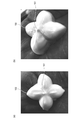
本実施形態の場合、泡の所定の目的形状は、90度回転対称形の配置とされた4つの花びらを有する花を模した形状である(図7(a)、図7(b)参照)。
図4(a)から図6(c)に示すように、本実施形態の場合、第2部材50は、1つの吐出路61を有しており、この吐出路61は、このような形状の泡に対応する形状に形成されている。
吐出路61は、例えば、複数(例えば4つ)の流入開口62と、1つの吐出開口63と、を有する。そして、吐出路61は、複数の流入開口62が吐出部(第2部材50)の内部で合流して共通の吐出開口63から液体101を吐出する合流吐出路である。
平面視において、各流入開口62は、吐出開口63と重なる位置に配置されている。ただし、板状部52は、複数の流入開口62どうしの間に位置する閉塞部67(図4(a)、図5(a)、図5(b)、図6(a)、図6(c))を有しており、平面視において、吐出開口63の一部分と閉塞部67とが重なっている。すなわち、吐出部(第2部材50)を吐出方向に視たときに、合流吐出路(吐出路61)の複数の流入開口62どうしの中間領域(閉塞部67)と、合流吐出路の吐出開口63の一部分と、が重なっている。換言すれば、閉塞部67の上側において、吐出開口63が1つに繋がっている。
閉塞部67と対応する位置に、吐出開口63の一部分が存在しているため、当該部分にも泡が回り込むので、当該部分からも泡を吐出することができる。また、閉塞部67と対応する部位において、吐出開口63からの泡の吐出量を適度に抑制することができる。
In the case of the present embodiment, the predetermined target shape of the bubble is a shape imitating a flower having four petals arranged in a 90-degree rotational symmetry shape (see FIGS. 7 (a) and 7 (b)). ..
As shown in FIGS. 4A to 6C, in the case of the present embodiment, the second member 50 has one discharge path 61, and the discharge path 61 has such a shape. It is formed in a shape corresponding to bubbles.
The discharge passage 61 has, for example, a plurality of (for example, four) inflow openings 62 and one discharge opening 63. The discharge path 61 is a combined discharge path in which a plurality of inflow openings 62 merge inside the discharge portion (second member 50) to discharge the liquid 101 from a common discharge opening 63.
In a plan view, each inflow opening 62 is arranged at a position overlapping the discharge opening 63. However, the plate-shaped portion 52 is a closed portion 67 located between the plurality of inflow openings 62 (FIGS. 4 (a), 5 (a), 5 (b), 6 (a), 6 (FIG. 6). c)), and a part of the discharge opening 63 and the closed portion 67 overlap each other in a plan view. That is, when the discharge portion (second member 50) is viewed in the discharge direction, the intermediate region (closed portion 67) between the plurality of inflow openings 62 of the combined discharge path (discharge path 61) and the discharge opening of the combined discharge path. It overlaps with a part of 63. In other words, on the upper side of the closing portion 67, the discharge openings 63 are connected to one.
Since a part of the discharge opening 63 exists at a position corresponding to the closed portion 67, the bubbles also wrap around the portion, so that the bubbles can be discharged from the portion as well. Further, the amount of foam discharged from the discharge opening 63 can be appropriately suppressed at the portion corresponding to the closed portion 67.

このように、吐出部(第2部材50)は、流入開口62が非形成となっている閉塞部67を有し、吐出部を吐出方向に視たときに、閉塞部67と、吐出開口63の一部分と、が重なっている。なお、閉塞部67は、第2部材50の厚み方向において、流入開口62側(吐出開口63側とは反対側)に配置されている。
また、第2部材50が閉塞部67を有しているとともに、閉塞部67の上側に吐出開口63の一部分が配置されていることによって、図6(a)に示すように、吐出方向に沿った断面において、流入開口62の開口幅(開口幅W11と開口幅W12との合計値)よりも吐出開口63の開口幅W21が大きくなっている。
As described above, the discharge portion (second member 50) has a closed portion 67 in which the inflow opening 62 is not formed, and when the discharge portion is viewed in the discharge direction, the closed portion 67 and the discharge opening 63 are formed. It overlaps with a part of. The closing portion 67 is arranged on the inflow opening 62 side (the side opposite to the discharge opening 63 side) in the thickness direction of the second member 50.
Further, since the second member 50 has the closing portion 67 and a part of the discharging opening 63 is arranged on the upper side of the closing portion 67, as shown in FIG. 6A, along the discharging direction. In the cross section, the opening width W21 of the discharge opening 63 is larger than the opening width of the inflow opening 62 (the total value of the opening width W11 and the opening width W12).

本実施形態の場合、流入開口62の開口面積よりも吐出開口63の開口面積が大きい。すなわち、一の吐出路61の流入開口62の総開口面積よりも、当該吐出路61の吐出開口63の開口面積が大きい。
また、貫通孔部65の横断面積よりも、ノズル部55の内部空間66の横断面積が大きい。ここで、貫通孔部65の横断面積とは、吐出方向に対して直交する断面における貫通孔部65の面積である。同様に、ノズル部55の内部空間66の内部空間の横断面積とは、吐出方向に対して直交する断面における内部空間66の面積である。本実施形態の場合、貫通孔部65の横断面積、並びに、内部空間66の横断面積は、それぞれの平断面積である。
In the case of the present embodiment, the opening area of the discharge opening 63 is larger than the opening area of the inflow opening 62. That is, the opening area of the discharge opening 63 of the discharge path 61 is larger than the total opening area of the inflow opening 62 of one discharge path 61.
Further, the cross-sectional area of the internal space 66 of the nozzle portion 55 is larger than the cross-sectional area of the through-hole portion 65. Here, the cross-sectional area of the through-hole portion 65 is the area of the through-hole portion 65 in a cross section orthogonal to the discharge direction. Similarly, the cross-sectional area of the internal space 66 of the internal space 66 of the nozzle portion 55 is the area of the internal space 66 in the cross section orthogonal to the ejection direction. In the case of the present embodiment, the cross-sectional area of the through hole portion 65 and the cross-sectional area of the internal space 66 are the respective flat cross-sectional areas.

上述のように、液体吐出ヘッド400は、前室21に泡(液体101)を流入させる予備流入口33を有する。
図3、図4(a)、図4(b)等に示すように、吐出部(第2部材50)において予備流入口33と対応する部位は、流入開口62が非形成となっている予備開口対向部64となっている。そして、吐出部を吐出方向に視たときに、予備開口対向部64と、吐出開口63の一部分と、が重なっている。
このため、吐出開口63において予備流入口33と対応する部位からの泡の吐出量を適度に抑制(ただし、適度に確保)することができる。
本実施形態の場合、吐出部(第2部材50)において予備流入口33と対応する部位は、予備流入口33と対向する部位である。
As described above, the liquid discharge head 400 has a preliminary inflow port 33 for flowing bubbles (liquid 101) into the anterior chamber 21.
As shown in FIGS. 3, 4 (a), 4 (b), etc., in the discharge portion (second member 50), the portion corresponding to the reserve inlet 33 is a reserve in which the inflow opening 62 is not formed. It is an opening facing portion 64. Then, when the discharge portion is viewed in the discharge direction, the preliminary opening facing portion 64 and a part of the discharge opening 63 overlap each other.
Therefore, in the discharge opening 63, the amount of foam discharged from the portion corresponding to the preliminary inflow port 33 can be appropriately suppressed (however, appropriately secured).
In the case of the present embodiment, the portion of the discharge portion (second member 50) corresponding to the preliminary inflow port 33 is a portion facing the preliminary inflow port 33.

本実施形態の場合、液体吐出容器100は、液体吐出ヘッド400が貯留部(容器本体10)側に向けて押し込まれる押圧操作に応じて液体101(泡)を吐出するように構成されており、吐出開口63は、押圧操作による押圧方向に対する反対方向に開口している。 In the case of the present embodiment, the liquid discharge container 100 is configured to discharge the liquid 101 (foam) in response to the pressing operation in which the liquid discharge head 400 is pushed toward the storage portion (container body 10). The discharge opening 63 opens in the direction opposite to the pressing direction by the pressing operation.

次に、動作を説明する。
液体吐出ヘッド400が押圧操作されていない通常状態では、液体吐出ヘッド400は上死点位置に位置している。
液体吐出ヘッド400に対する押圧操作は、図1に示すように手などの被吐出体22で液体吐出ヘッド400の上端(周壁56の上縁56c)の開口56eを塞いだ状態(つまり、被吐出体22が空間59を介して吐出開口63と対向する状態)で、被吐出体22によって液体吐出ヘッド400を押圧することにより行うことができる。
Next, the operation will be described.
In the normal state where the liquid discharge head 400 is not pressed, the liquid discharge head 400 is located at the top dead center position.
In the pressing operation against the liquid discharge head 400, as shown in FIG. 1, the discharged body 22 such as a hand closes the opening 56e of the upper end (upper edge 56c of the peripheral wall 56) of the liquid discharge head 400 (that is, the discharged body). This can be done by pressing the liquid discharge head 400 with the ejected body 22 in a state where the 22 faces the discharge opening 63 through the space 59).

液体吐出ヘッド400に対する押圧操作が行われると、液体吐出ヘッド400及びピストンガイド80がポンプ部75内の付勢部材の付勢に抗して容器本体10に対して相対的に下降する。
この際に、ポンプ部75の作用により液体101及び空気がフォーマー機構19の気液混合部20に供給され、該気液混合部20にて泡が生成される。気液混合部20にて生成された泡は、メッシュ24を通過することによって、よりきめ細かく均一な泡となる。このようにしてフォーマー機構19にて生成された泡は、筒部31の内部を通過して予備流入口33から前室21に吐出され、該前室21にて広がる。
更に、泡は吐出路61に流入し、吐出路61によって絞り込まれて、吐出開口63から吐出される。すなわち、泡は、各流入開口62から板状部52の各貫通孔部65に流入し、各貫通孔部65からノズル部55の内部空間66に流入し、吐出開口63から空間59に吐出される。
泡は吐出路61を通過することによって、所定の目的形状(本実施形態では花を模した形状)に整形され、開口56eを塞いでいる被吐出体22の下面に付着する。すなわち、周壁56に対する押圧操作によって吐出開口63から飛び出した泡が被吐出体22に転写され、所定の目的形状に整形された泡である造形物150が被吐出体22の下面に付着した状態となる。
その後、液体吐出ヘッド400に対する押圧操作が解除されると、付勢部材の付勢に従ってピストンガイド80及び液体吐出ヘッド400が上昇し、液体吐出ヘッド400が上死点位置に復帰する。
その後、被吐出体22を開口56eの上方に持ち上げて裏返すことにより、被吐出体22上に造形物150が形成された状態となる。
ピストンガイド80が上昇する際に、容器本体10内の液体101がディップチューブ77を介してポンプ部75内に吸い上げられる。
なお、ここで説明したキャップ200(ポンプ部75を含む)の構造および動作は一例であり、キャップ200の構造としては、本発明の要旨を逸脱しない範囲において、その他の広く知られている構造のものを本実施形態に適用しても何ら差し支えが無い。
When the pressing operation on the liquid discharge head 400 is performed, the liquid discharge head 400 and the piston guide 80 descend relative to the container body 10 against the urging of the urging member in the pump portion 75.
At this time, the liquid 101 and air are supplied to the gas-liquid mixing unit 20 of the former mechanism 19 by the action of the pump unit 75, and bubbles are generated in the gas-liquid mixing unit 20. The bubbles generated in the gas-liquid mixing section 20 pass through the mesh 24 to become finer and more uniform bubbles. The bubbles generated by the former chamber mechanism 19 in this way pass through the inside of the tubular portion 31 and are discharged from the preliminary inflow port 33 to the anterior chamber 21 and spread in the anterior chamber 21.
Further, the bubbles flow into the discharge path 61, are narrowed down by the discharge path 61, and are discharged from the discharge opening 63. That is, the bubbles flow from each inflow opening 62 into each through hole portion 65 of the plate-shaped portion 52, flow into the internal space 66 of the nozzle portion 55 from each through hole portion 65, and are discharged from the discharge opening 63 into the space 59. To.
By passing through the discharge path 61, the bubbles are shaped into a predetermined target shape (a shape imitating a flower in this embodiment) and adhere to the lower surface of the discharged body 22 blocking the opening 56e. That is, the foam ejected from the discharge opening 63 by the pressing operation against the peripheral wall 56 is transferred to the ejected body 22, and the shaped object 150, which is a bubble shaped into a predetermined target shape, adheres to the lower surface of the ejected body 22. Become.
After that, when the pressing operation on the liquid discharge head 400 is released, the piston guide 80 and the liquid discharge head 400 rise according to the urging of the urging member, and the liquid discharge head 400 returns to the top dead center position.
After that, by lifting the ejected body 22 above the opening 56e and turning it over, the modeled object 150 is formed on the ejected body 22.
When the piston guide 80 rises, the liquid 101 in the container body 10 is sucked up into the pump portion 75 via the dip tube 77.
The structure and operation of the cap 200 (including the pump portion 75) described here is an example, and the structure of the cap 200 is of other widely known structures as long as it does not deviate from the gist of the present invention. There is no problem even if the thing is applied to this embodiment.

泡造形物を被吐出体22上に好適に受け取ることができるように、板状部52の上面と周壁56の上縁56cとの高低差、すなわち板状部52の上面を基準とした周壁56の高さ寸法は、板状部52の上面とノズル部55の上端との高低差、すなわちノズル部55の高さ寸法の2倍以上であることが好ましく、3倍以上であることが更に好ましく、また、10倍以下であることが好ましく、8倍以下であることが更に好ましい。
また、吐出開口63と周壁56の上縁56cとの高低差は、5mm以上20mm以下であることが好ましく、7mm以上18mm以下であることが更に好ましい。
また、ノズル部55の高さ寸法(板状部52からのノズル部55の突出長)は、泡を吐出開口63から被吐出体22上に良好に受け取れるようにする観点から、1mm以上であることが好ましく、2mm以上であることが更に好ましく、また10mm以下であることが好ましく、8mm以下であることが更に好ましい。
また、吐出開口63の対向位置に被吐出体22を配置せずに周壁56に対して押圧操作が行われた場合に、吐出開口63から吐出される泡が周壁56の上縁56cよりも上方に飛び出すように、ポンプ部75等のフォーマー機構19の構造、周壁56やノズル部55の高さ寸法等が設定されていることが好ましい。
The height difference between the upper surface of the plate-shaped portion 52 and the upper edge 56c of the peripheral wall 56, that is, the peripheral wall 56 with reference to the upper surface of the plate-shaped portion 52 so that the foamed object can be suitably received on the ejected body 22. The height dimension of the plate-shaped portion 52 is preferably at least twice the height difference between the upper surface of the plate-shaped portion 52 and the upper end of the nozzle portion 55, that is, at least twice the height dimension of the nozzle portion 55, and more preferably at least three times. Further, it is preferably 10 times or less, and more preferably 8 times or less.
Further, the height difference between the discharge opening 63 and the upper edge 56c of the peripheral wall 56 is preferably 5 mm or more and 20 mm or less, and more preferably 7 mm or more and 18 mm or less.
Further, the height dimension of the nozzle portion 55 (the protruding length of the nozzle portion 55 from the plate-shaped portion 52) is 1 mm or more from the viewpoint of allowing bubbles to be satisfactorily received on the ejected body 22 from the ejection opening 63. It is preferably 2 mm or more, more preferably 10 mm or less, and even more preferably 8 mm or less.
Further, when the pressing operation is performed against the peripheral wall 56 without arranging the ejected body 22 at the position facing the discharge opening 63, the bubbles discharged from the discharge opening 63 are above the upper edge 56c of the peripheral wall 56. It is preferable that the structure of the former mechanism 19 such as the pump portion 75, the height dimension of the peripheral wall 56 and the nozzle portion 55, and the like are set so as to pop out.

吐出開口63から泡をスムーズに吐出させ、手などの被吐出体22上に安定して特定形状の泡を好適に形成する観点から、30mm/sの速度で液体吐出ヘッド400を押し下げるときの押圧力が、1N以上であることが好ましく、5N以上であることが更に好ましく、また40N以下であることが好ましく、35N以下であることが更に好ましい。 Pushing when pushing down the liquid discharge head 400 at a speed of 30 mm / s from the viewpoint of smoothly discharging bubbles from the discharge opening 63 and stably forming bubbles of a specific shape on the discharged body 22 such as a hand. The pressure is preferably 1N or more, more preferably 5N or more, more preferably 40N or less, and even more preferably 35N or less.

1回の泡の吐出動作により吐出される泡の体積(単位泡体積)は、特に限定されないが、例えば、3cm以上30cm以下であることが好ましく、5cm以上20cm以下であることがより好ましく、10cm以上であることが更に好ましい。 The volume of bubbles (unit volume) discharged by one bubble ejection operation is not particularly limited , but is preferably 3 cm 3 or more and 30 cm 3 or less, and is preferably 5 cm 3 or more and 20 cm 3 or less. More preferably, it is more preferably 10 cm 3 or more.

吐出開口63の前段に配置された前室21において泡が広がって該前室21が泡で満たされた後、泡が吐出開口63から吐出されるようにできるため、泡を吐出開口63の全域に十分に行き渡らせることが容易となり、泡を吐出開口63によって所定の目的形状に形成しやすくなる。また、予備開口対向部64が配置されていることにより、予備流入口33から吐出された泡が前室21において広がり易くなっている。 After the bubbles are spread in the front chamber 21 arranged in front of the discharge opening 63 and the front chamber 21 is filled with the bubbles, the bubbles can be discharged from the discharge opening 63, so that the bubbles can be discharged from the entire area of the discharge opening 63. It becomes easy to sufficiently spread the bubbles, and it becomes easy to form bubbles in a predetermined target shape by the discharge opening 63. Further, since the preliminary opening facing portion 64 is arranged, the bubbles discharged from the preliminary inflow port 33 are easily spread in the front chamber 21.

また、吐出開口63がノズル部55の先端に形成されていることにより、被吐出体22側へ、泡を安定して吐出することができるとともに、吐出開口63からの泡切れ(吐出開口63からの泡の分離性)を良好にできる。 Further, since the discharge opening 63 is formed at the tip of the nozzle portion 55, bubbles can be stably discharged to the discharged body 22 side, and bubbles are cut off from the discharge opening 63 (from the discharge opening 63). (Foam separability) can be improved.

ここで、比較形態1及び比較形態2を説明する。
比較形態1に係る液体吐出容器は、上述した第2部材50の代わりに、図15(a)から図15(c)に示す第2部材500を備えている点で、本実施形態に係る液体吐出容器100と相違しており、その他の点では、本実施形態に係る液体吐出容器100と同様に構成されている。図15(a)から図15(c)に示す第2部材500の場合、平面視において、流入開口620の形状と吐出開口630の形状とが互いに同一であり、いずれも十字型となっている。吐出開口630の平面形状は、本実施形態に係る液体吐出容器100の吐出開口63の平面形状と同一である。また、吐出路610の平断面形状は、第2部材500の厚み方向における位置にかかわらず一定となっている。図15(a)から図15(c)に示す第2部材500の板状部520は、予備流入口33の一部分と対向する予備開口対向部640を有するが、平面視において吐出開口630と重なる閉塞部67(図5(b))は有していない。
比較形態2に係る液体吐出容器は、上述した第2部材50の代わりに、図16(a)から図16(c)に示す第2部材500を備えている点で、本実施形態に係る液体吐出容器100と相違しており、その他の点では、本実施形態に係る液体吐出容器100と同様に構成されている。図16(a)から図16(c)に示す第2部材500の場合、それぞれ平面形状が直線状の4つの吐出路610を有しており、これら4つの吐出路610が、中央部が空白となった十字型に配置されている。各吐出路610について、平面視において、流入開口620の形状と吐出開口630の形状とが互いに同一であり、いずれも直線状となっている。各吐出路610の平断面形状は、第2部材500の厚み方向における位置にかかわらず一定となっている。図16(a)から図16(c)に示す第2部材500の板状部520は、予備流入口33と対向する予備開口対向部640を有するが、平面視において吐出開口630と重なる閉塞部67(図5(b))は有していない。
Here, the comparative form 1 and the comparative form 2 will be described.
The liquid discharge container according to the comparative embodiment 1 includes the second member 500 shown in FIGS. 15 (a) to 15 (c) instead of the second member 50 described above, and the liquid according to the present embodiment is provided. It is different from the discharge container 100, and is otherwise configured in the same manner as the liquid discharge container 100 according to the present embodiment. In the case of the second member 500 shown in FIGS. 15 (a) to 15 (c), the shape of the inflow opening 620 and the shape of the discharge opening 630 are the same in the plan view, and both are cross-shaped. .. The planar shape of the discharge opening 630 is the same as the planar shape of the discharge opening 63 of the liquid discharge container 100 according to the present embodiment. Further, the flat cross-sectional shape of the discharge path 610 is constant regardless of the position of the second member 500 in the thickness direction. The plate-shaped portion 520 of the second member 500 shown in FIGS. 15 (a) to 15 (c) has a preliminary opening facing portion 640 facing a part of the preliminary inflow port 33, but overlaps with the discharge opening 630 in a plan view. It does not have a closed portion 67 (FIG. 5 (b)).
The liquid discharge container according to the comparative embodiment 2 includes the second member 500 shown in FIGS. 16A to 16C instead of the second member 50 described above, and the liquid according to the present embodiment is provided. It is different from the discharge container 100, and is otherwise configured in the same manner as the liquid discharge container 100 according to the present embodiment. In the case of the second member 500 shown in FIGS. 16A to 16C, each of the second member 500 has four discharge passages 610 having a linear planar shape, and these four discharge passages 610 have a blank central portion. It is arranged in a cross shape. For each discharge path 610, the shape of the inflow opening 620 and the shape of the discharge opening 630 are the same as each other in a plan view, and both are linear. The plank cross-sectional shape of each discharge path 610 is constant regardless of the position of the second member 500 in the thickness direction. The plate-shaped portion 520 of the second member 500 shown in FIGS. 16A to 16C has a preliminary opening facing portion 640 facing the preliminary inlet 33, but is a closed portion overlapping the discharge opening 630 in a plan view. 67 (FIG. 5 (b)) does not have.

図17(a)及び図17(b)は、比較形態1に係る液体吐出容器を用いて実際に形成した泡の造形物160を撮像した画像である。図17(a)及び図17(b)に示す造形物160は、花を模した形状に形成されているが、吐出開口630の中央部から吐出される泡の量が多いため、造形物160において花びらを模した部分どうしの間には、泡が薄膜状に形成された薄膜部161が存在する。
図17(c)及び図17(d)は、比較形態2に係る液体吐出容器を用いて実際に形成した泡の造形物160を撮像した画像である。図17(c)及び図17(d)に示す造形物160は、花を模した形状に形成されているが、予備開口対向部640と対応する部位に供給される泡の量が少ないため、造形物160の中央部162に窪みが形成されている。
17 (a) and 17 (b) are images of an image of a foam model 160 actually formed using the liquid discharge container according to Comparative Form 1. The model 160 shown in FIGS. 17 (a) and 17 (b) is formed in a shape imitating a flower, but since the amount of bubbles discharged from the central portion of the discharge opening 630 is large, the model 160 is formed. There is a thin film portion 161 in which bubbles are formed in the form of a thin film between the portions that imitate the petals.
17 (c) and 17 (d) are images of the foam model 160 actually formed using the liquid discharge container according to Comparative Form 2. The model 160 shown in FIGS. 17 (c) and 17 (d) is formed in a shape imitating a flower, but the amount of bubbles supplied to the portion corresponding to the preliminary opening facing portion 640 is small. A depression is formed in the central portion 162 of the model 160.

図7(a)及び図7(b)は、本実施形態に係る液体吐出容器100を用いて実際に形成した造形物150を撮像した画像である。図7(a)及び図7(b)に示す造形物150は、花を模した形状に形成されており、比較形態1で形成されたような薄膜部161が実質的に形成されず、比較形態2で形成されたような中央部162の窪みも実質的に形成されなかった。
すなわち、本実施形態によれば、吐出方向に沿った断面において流入開口62の開口幅よりも吐出開口63の開口幅が大きいことによって、泡の造形物150をより正確に所望の形状にすることが可能である。
7 (a) and 7 (b) are images of an image of a model 150 actually formed by using the liquid discharge container 100 according to the present embodiment. The model 150 shown in FIGS. 7 (a) and 7 (b) is formed in a shape imitating a flower, and the thin film portion 161 as formed in the comparative form 1 is not substantially formed, and the comparison is made. The depression in the central portion 162 as formed in the second form was not substantially formed.
That is, according to the present embodiment, the opening width of the discharge opening 63 is larger than the opening width of the inflow opening 62 in the cross section along the discharge direction, so that the foam model 150 is more accurately formed into a desired shape. Is possible.

なお、本実施形態の場合、図4(a)から図6(c)に示すように、十字型の吐出開口63が中央部においても開口しているため、図7(a)及び図7(b)に示すように、花を模した造形物150の中央部151には、雌しべを模したような小突起が形成されている。このように、表面に微細な起伏を有する立体形状の造形物150も形成することができる。 In the case of the present embodiment, as shown in FIGS. 4 (a) to 6 (c), since the cross-shaped discharge opening 63 is also opened in the central portion, FIGS. 7 (a) and 7 (c). As shown in b), a small protrusion that imitates a pistil is formed in the central portion 151 of the shaped object 150 that imitates a flower. In this way, it is possible to form a three-dimensional shaped object 150 having fine undulations on the surface.

〔第2実施形態〕
次に、図8(a)から図11を用いて第2実施形態を説明する。
本実施形態に係る液体吐出容器は、第2部材50が以下に説明する形状となっている点で、第1実施形態に係る液体吐出容器100と相違しており、その他の点では第1実施形態に係る液体吐出容器100と同様に構成されている。
[Second Embodiment]
Next, the second embodiment will be described with reference to FIGS. 8A to 11.
The liquid discharge container according to the present embodiment is different from the liquid discharge container 100 according to the first embodiment in that the second member 50 has a shape described below, and in other respects, the first embodiment. It is configured in the same manner as the liquid discharge container 100 according to the embodiment.

本実施形態の場合、図11に示すように、造形物150は、飛行機を模した形状である。
このような造形物150を形成するために、吐出路61は、以下に説明するような形状となっている。
図8(a)及び図9(a)に示すように、吐出開口63の平面形状は、飛行機の胴体部と対応する形状の直線状の部分と、左右一対の主翼とそれぞれ対応する2つの直線状の部分と、左右一対の水平尾翼とそれぞれ対応する2つの直線状の部分と、が相互に一体化された形状となっている。
図8(b)及び図9(b)に示すように、本実施形態の場合、吐出路61は、6つの流入開口62を有する。より詳細には、吐出路61は、飛行機の胴体部の前部と対応する形状の直線状の流入開口62と、胴体部の後部と対応する形状の直線状の流入開口62と、を互いに同一直線上に有する。更に、吐出路61は、左側の主翼の基端部を除く部分と対応する形状の直線状の流入開口62と、右側の主翼の基端部を除く部分と対応する形状の直線状の流入開口62と、左側の水平尾翼の基端部を除く部分と対応する形状の直線状の流入開口62と、右側の水平尾翼の基端部を除く部分と対応する形状の直線状の流入開口62と、を有する。
平面視において、各流入開口62は、吐出開口63と重なる位置に配置されている。ただし、板状部52は、複数の流入開口62どうしの間に位置する閉塞部67(図8(a)、図8(b)、図9(a)、図9(b)、図10(a)、図10(c))を有しており、平面視において、吐出開口63の一部分と閉塞部67とが重なっている。
In the case of the present embodiment, as shown in FIG. 11, the modeled object 150 has a shape imitating an airplane.
In order to form such a model 150, the discharge path 61 has a shape as described below.
As shown in FIGS. 8A and 9A, the planar shape of the discharge opening 63 is a linear portion having a shape corresponding to the fuselage portion of an airplane and two straight lines corresponding to a pair of left and right main wings, respectively. The shape portion and the two linear portions corresponding to the pair of left and right horizontal stabilizers are integrated with each other.
As shown in FIGS. 8 (b) and 9 (b), in the case of the present embodiment, the discharge path 61 has six inflow openings 62. More specifically, the discharge path 61 has a linear inflow opening 62 having a shape corresponding to the front portion of the fuselage portion of the airplane and a linear inflow opening 62 having a shape corresponding to the rear portion of the fuselage portion. Have in a straight line. Further, the discharge path 61 has a linear inflow opening 62 having a shape corresponding to the portion excluding the base end portion of the left main wing and a linear inflow opening 62 having a shape corresponding to the portion excluding the base end portion of the right main wing. 62, a linear inflow opening 62 having a shape corresponding to the portion excluding the base end of the horizontal stabilizer on the left side, and a linear inflow opening 62 having a shape corresponding to the portion excluding the base end portion of the horizontal stabilizer on the right side. , Have.
In a plan view, each inflow opening 62 is arranged at a position overlapping the discharge opening 63. However, the plate-shaped portion 52 is a closed portion 67 located between the plurality of inflow openings 62 (FIGS. 8 (a), 8 (b), 9 (a), 9 (b), 10 (FIG. 8)). It has a) and FIG. 10 (c)), and a part of the discharge opening 63 and the closed portion 67 overlap each other in a plan view.

図10(a)に示すように、本実施形態の場合も、吐出方向に沿った断面において、流入開口62の開口幅(図10(a)に示す開口幅W11と開口幅W12との合計値)よりも吐出開口63の開口幅W21が大きい。
より詳細には、本実施形態の場合も、流入開口62の開口面積よりも吐出開口63の開口面積が大きい。
また、本実施形態の場合も、吐出路61は、複数の流入開口62が吐出部(第2部材50)の内部で合流して共通の吐出開口63から液体を吐出する合流吐出路となっている。
そして、吐出部(第2部材50)を吐出方向に視たときに、合流吐出路(吐出路61)の複数の流入開口62どうしの中間領域(閉塞部67)と、合流吐出路の吐出開口63の一部分と、が重なっている。
本実施形態の場合も、液体吐出ヘッドは、前室に液体を流入させる予備流入口を有し、吐出部において予備流入口と対応する部位は、流入開口62が非形成となっている予備開口対向部64であり、吐出部を吐出方向に視たときに、予備開口対向部64と、吐出開口63の一部分と、が重なっている。
本実施形態の場合も、吐出部は、一方の面に流入開口62を有する板状部52と、板状部52の他方の面から突出していて先端に吐出開口63を有するノズル部55とを含み、吐出路61は、板状部52を貫通している貫通孔部65と、ノズル部55の内部空間66とを含み、貫通孔部65とノズル部55の内部空間66とが相互に連通しており、貫通孔部65の横断面積よりも、ノズル部55の内部空間66の横断面積が大きい。
本実施形態の場合も、液体吐出容器は、液体吐出ヘッドが貯留部側に向けて押し込まれる押圧操作に応じて液体を吐出するように構成されており、吐出開口63は、押圧操作による押圧方向に対する反対方向に開口している。ここでいう押圧方向は、押圧操作によって液体吐出ヘッドが移動する方向(貯留部に対する相対的な移動方向)である。
As shown in FIG. 10A, also in the case of the present embodiment, the opening width of the inflow opening 62 (the total value of the opening width W11 and the opening width W12 shown in FIG. 10A) in the cross section along the discharge direction. ), The opening width W21 of the discharge opening 63 is larger.
More specifically, also in the present embodiment, the opening area of the discharge opening 63 is larger than the opening area of the inflow opening 62.
Further, also in the case of the present embodiment, the discharge path 61 is a combined discharge path in which a plurality of inflow openings 62 merge inside the discharge portion (second member 50) to discharge the liquid from the common discharge opening 63. There is.
Then, when the discharge portion (second member 50) is viewed in the discharge direction, the intermediate region (closed portion 67) between the plurality of inflow openings 62 of the combined discharge path (discharge path 61) and the discharge opening of the combined discharge path. It overlaps with a part of 63.
Also in the present embodiment, the liquid discharge head has a preliminary inflow port for flowing the liquid into the anterior chamber, and the portion corresponding to the preliminary inflow port in the discharge portion is a preliminary opening in which the inflow opening 62 is not formed. It is a facing portion 64, and when the discharging portion is viewed in the discharging direction, the preliminary opening facing portion 64 and a part of the discharging opening 63 overlap each other.
Also in the case of the present embodiment, the discharge portion includes a plate-shaped portion 52 having an inflow opening 62 on one surface and a nozzle portion 55 protruding from the other surface of the plate-shaped portion 52 and having a discharge opening 63 at the tip. The discharge path 61 includes a through hole portion 65 penetrating the plate-shaped portion 52 and an internal space 66 of the nozzle portion 55, and the through hole portion 65 and the internal space 66 of the nozzle portion 55 communicate with each other. The cross-sectional area of the internal space 66 of the nozzle portion 55 is larger than the cross-sectional area of the through-hole portion 65.
Also in the present embodiment, the liquid discharge container is configured to discharge the liquid in response to the pressing operation in which the liquid discharge head is pushed toward the storage portion side, and the discharge opening 63 is in the pressing direction by the pressing operation. It opens in the opposite direction to. The pressing direction referred to here is a direction in which the liquid discharge head is moved by the pressing operation (moving direction relative to the storage portion).

〔第3実施形態〕
次に、図12(a)から図14(b)を用いて第3実施形態を説明する。
本実施形態に係る液体吐出容器は、第2部材50が以下に説明する形状となっている点で、第1実施形態に係る液体吐出容器100と相違しており、その他の点では第1実施形態に係る液体吐出容器100と同様に構成されている。
[Third Embodiment]
Next, the third embodiment will be described with reference to FIGS. 12 (a) to 14 (b).
The liquid discharge container according to the present embodiment is different from the liquid discharge container 100 according to the first embodiment in that the second member 50 has a shape described below, and in other respects, the first embodiment. It is configured in the same manner as the liquid discharge container 100 according to the embodiment.

上記の第1実施形態の場合、吐出路61が複数の流入開口62を有しているのに対し、本実施形態の場合、吐出路61が有する流入開口62の数は1つである。
本実施形態の場合、流入開口62は、平面形状が十字型となっている。
より詳細には、図12(b)及び図13(b)に示すように、流入開口62は、それぞれ平面形状が直線状の4つの太幅部62aと、それぞれ平面形状が直線状に形成されていて太幅部62aよりも細幅に形成されている4つの細幅部62bと、を含んで構成されている。
太幅部62aと細幅部62bとは1対1で対応しており、互いに対応する太幅部62aと細幅部62bとは同一直線上に配置されている。
4つの細幅部62bが十字状に配置されており、各細幅部62bの延長上にそれぞれ太幅部62aが配置されている。
貫通孔部65の平面形状は、流入開口62の平面形状と同一となっている。
In the case of the first embodiment described above, the discharge passage 61 has a plurality of inflow openings 62, whereas in the case of the present embodiment, the number of inflow openings 62 of the discharge passage 61 is one.
In the case of the present embodiment, the inflow opening 62 has a cross-shaped planar shape.
More specifically, as shown in FIGS. 12 (b) and 13 (b), the inflow opening 62 is formed with four wide portions 62a having a linear planar shape and a linear planar shape, respectively. It is configured to include four narrow width portions 62b formed to be narrower than the wide width portion 62a.
The wide portion 62a and the narrow width portion 62b have a one-to-one correspondence, and the wide width portion 62a and the narrow width portion 62b corresponding to each other are arranged on the same straight line.
The four narrow portions 62b are arranged in a cross shape, and the wide portions 62a are arranged on the extension of each narrow portion 62b.
The planar shape of the through hole portion 65 is the same as the planar shape of the inflow opening 62.

図12(a)及び図13(a)に示すように、本実施形態の場合も、ノズル部55、内部空間66及び吐出開口63の形状は、第1実施形態と同一である。
吐出開口63において、各太幅部62aと対応する部分は、太幅部62aと同じ形状となっている(図14(b)参照)。
吐出開口63において、各細幅部62bと対応する部分は、太幅部62aと同じ幅寸法、すなわち細幅部62bよりも太幅に形成されている。
このため、図13(b)及び図14(c)に示すように、板状部52は、平面視において吐出開口63の一部分と重なる閉塞部67を有する。
つまり、閉塞部67が形成されている分だけ。流入開口62及び貫通孔部65の幅が、部分的に、吐出開口63よりも細くなっている。
このため、吐出開口63の中央部から吐出される泡の量を低減できるため、第1実施形態と同様に、泡の造形物をより正確に所望の形状にすることが可能となる。すなわち、本実施形態の場合も、第1実施形態と同様に、花を模した形状の泡の造形物を形成することができる。
As shown in FIGS. 12A and 13A, the shapes of the nozzle portion 55, the internal space 66, and the discharge opening 63 are the same as those of the first embodiment also in the present embodiment.
In the discharge opening 63, the portion corresponding to each wide portion 62a has the same shape as the wide portion 62a (see FIG. 14B).
In the discharge opening 63, the portion corresponding to each narrow width portion 62b is formed to have the same width dimension as the wide width portion 62a, that is, to be wider than the narrow width portion 62b.
Therefore, as shown in FIGS. 13 (b) and 14 (c), the plate-shaped portion 52 has a closed portion 67 that overlaps a part of the discharge opening 63 in a plan view.
That is, only the amount that the closed portion 67 is formed. The width of the inflow opening 62 and the through hole portion 65 is partially narrower than that of the discharge opening 63.
Therefore, since the amount of foam discharged from the central portion of the discharge opening 63 can be reduced, it is possible to more accurately shape the foamed object into a desired shape, as in the first embodiment. That is, also in the case of the present embodiment, it is possible to form a foam model having a shape imitating a flower, as in the first embodiment.

図14(c)に示すように、本実施形態の場合も、吐出方向に沿った断面において、流入開口62(細幅部62b)の開口幅W11よりも吐出開口63の開口幅W21が大きい。
より詳細には、本実施形態の場合も、流入開口62の開口面積よりも吐出開口63の開口面積が大きい。
本実施形態の場合も、液体吐出ヘッドは、前室に液体を流入させる予備流入口を有し、吐出部において予備流入口と対応する部位は、流入開口62が非形成となっている予備開口対向部64であり、吐出部を吐出方向に視たときに、予備開口対向部64と、吐出開口63の一部分と、が重なっている。
本実施形態の場合も、吐出部は、一方の面に流入開口62を有する板状部52と、板状部52の他方の面から突出していて先端に吐出開口63を有するノズル部55とを含み、吐出路61は、板状部52を貫通している貫通孔部65と、ノズル部55の内部空間66とを含み、貫通孔部65とノズル部55の内部空間66とが相互に連通しており、貫通孔部65の横断面積よりも、ノズル部55の内部空間66の横断面積が大きい(図14(c))。
本実施形態の場合も、液体吐出容器は、液体吐出ヘッドが貯留部側に向けて押し込まれる押圧操作に応じて液体を吐出するように構成されており、吐出開口63は、押圧操作による押圧方向に対する反対方向に開口している。
As shown in FIG. 14 (c), also in the present embodiment, the opening width W21 of the discharge opening 63 is larger than the opening width W11 of the inflow opening 62 (narrow width portion 62b) in the cross section along the discharge direction.
More specifically, also in the present embodiment, the opening area of the discharge opening 63 is larger than the opening area of the inflow opening 62.
Also in the present embodiment, the liquid discharge head has a preliminary inflow port for flowing the liquid into the anterior chamber, and the portion corresponding to the preliminary inflow port in the discharge portion is a preliminary opening in which the inflow opening 62 is not formed. It is a facing portion 64, and when the discharging portion is viewed in the discharging direction, the preliminary opening facing portion 64 and a part of the discharging opening 63 overlap each other.
Also in the case of the present embodiment, the discharge portion includes a plate-shaped portion 52 having an inflow opening 62 on one surface and a nozzle portion 55 protruding from the other surface of the plate-shaped portion 52 and having a discharge opening 63 at the tip. The discharge path 61 includes a through hole portion 65 penetrating the plate-shaped portion 52 and an internal space 66 of the nozzle portion 55, and the through hole portion 65 and the internal space 66 of the nozzle portion 55 communicate with each other. The cross-sectional area of the internal space 66 of the nozzle portion 55 is larger than the cross-sectional area of the through-hole portion 65 (FIG. 14 (c)).
Also in the present embodiment, the liquid discharge container is configured to discharge the liquid in response to the pressing operation in which the liquid discharge head is pushed toward the storage portion side, and the discharge opening 63 is in the pressing direction by the pressing operation. It opens in the opposite direction to.

本発明は上述の実施形態に限定されるものではなく、本発明の目的が達成される限りにおける種々の変形、改良等の態様も含む。 The present invention is not limited to the above-described embodiment, and includes various modifications, improvements, and the like as long as the object of the present invention is achieved.

<変形例1>
例えば、上記の各実施形態では、吐出路61が1つの吐出開口63を有する例を説明したが、本発明は、この例に限らず、吐出路61が複数の流入開口62と複数の吐出開口63とを有していてもよい。
より詳細には、例えば、吐出路61は、複数の流入開口62と、複数の流入開口62の各々と対応している同数の吐出開口63と、を含んでいる。そして、吐出部(第2部材50)を吐出方向に視たときに、少なくともいずれか1つの吐出開口63は、当該吐出開口63と対応する流入開口62と比べて、他の吐出開口63側に向けて広がっている。
例えば、第1実施形態と似たような吐出路61の形状であって、吐出路61の中央部において吐出開口63が閉塞している形状の第2部材50を用いることができる。すなわち、4つの直線状の吐出開口63が十字型に配置されており、且つ、各吐出開口63において他の吐出開口63に近い側の端部の下側に、閉塞部67が形成されている第2部材50を用いることができる。
図5(b)を用いて変形例1を説明すると、各吐出開口63の形状は、各流入開口62とほぼ同等の形状となっていて、各吐出開口63は流入開口62と重なっているが、吐出開口63は、流入開口62と比べて、吐出開口63どうしの中間点68に向けて広がっている。
このような第2部材50を用いた場合、例えば、図7(a)及び図7(b)に示す造形物150と比べて、中央部151をより平坦に形成することも可能である。
また、図9(b)を用いて変形例1を説明すると、例えば、飛行機の胴体部と対応する2つの吐出開口63の形状は、飛行機の胴体部と対応する2つの流入開口62の各々とほぼ同等の形状となっていて、各吐出開口63は流入開口62と重なっているが、各吐出開口63は、流入開口62と比べて、これら2つの吐出開口63どうしの中間点68に向けて広がっている。また、例えば、主翼と対応する2つの吐出開口63が形成されており、これら吐出開口63は、それぞれ対応する流入開口62と比べて、胴体部の前部と対応する吐出開口63に向けて広がっている。また、例えば、水平尾翼と対応する2つの吐出開口63が形成されており、これら吐出開口63は、それぞれ対応する流入開口62と比べて、胴体部の後部と対応する吐出開口63に向けて広がっている。
<Modification 1>
For example, in each of the above embodiments, an example in which the discharge path 61 has one discharge opening 63 has been described, but the present invention is not limited to this example, and the discharge path 61 has a plurality of inflow openings 62 and a plurality of discharge openings. 63 and may have.
More specifically, for example, the discharge passage 61 includes a plurality of inflow openings 62 and the same number of discharge openings 63 corresponding to each of the plurality of inflow openings 62. Then, when the discharge portion (second member 50) is viewed in the discharge direction, at least one of the discharge openings 63 is closer to the other discharge openings 63 than the inflow opening 62 corresponding to the discharge opening 63. It is spreading toward.
For example, a second member 50 having a shape similar to that of the first embodiment and having a shape in which the discharge opening 63 is closed at the center of the discharge path 61 can be used. That is, the four linear discharge openings 63 are arranged in a cross shape, and the closing portion 67 is formed in each discharge opening 63 below the end portion on the side closer to the other discharge openings 63. The second member 50 can be used.
Explaining the first modification with reference to FIG. 5B, the shape of each discharge opening 63 is substantially the same as that of each inflow opening 62, and each discharge opening 63 overlaps with the inflow opening 62. The discharge opening 63 is wider toward the midpoint 68 between the discharge openings 63 than the inflow opening 62.
When such a second member 50 is used, for example, it is possible to form the central portion 151 more flatly as compared with the model 150 shown in FIGS. 7 (a) and 7 (b).
Further, to explain the modification 1 with reference to FIG. 9B, for example, the shapes of the two discharge openings 63 corresponding to the fuselage portion of the airplane correspond to each of the two inflow openings 62 corresponding to the fuselage portion of the airplane. The shape is almost the same, and each discharge opening 63 overlaps with the inflow opening 62, but each discharge opening 63 is directed toward the intermediate point 68 between these two discharge openings 63 as compared with the inflow opening 62. It has spread. Further, for example, two discharge openings 63 corresponding to the main wing are formed, and these discharge openings 63 widen toward the front portion of the fuselage portion and the corresponding discharge openings 63 as compared with the corresponding inflow openings 62, respectively. ing. Further, for example, two discharge openings 63 corresponding to the horizontal stabilizer are formed, and these discharge openings 63 widen toward the rear portion of the fuselage portion and the corresponding discharge openings 63 as compared with the corresponding inflow openings 62, respectively. ing.

<変形例2>
また、吐出路61が、3つ以上の流入開口62と、3つ以上の流入開口62の各々と対応している3つ以上の吐出開口63と、を含んでいる場合であって、且つ、これら吐出開口63どうしが離散的に配置されている場合には、吐出開口63が広がる方向が、他の吐出開口63側の方向とは限らない場合がある。
この場合、例えば、吐出部(第2部材50)を吐出方向に視たときに、少なくともいずれか1つの吐出開口63は、当該吐出開口63と対応する流入開口62と比べて、3つ以上の流入開口62どうしの中間領域に向けて広がっている。
<Modification 2>
Further, when the discharge path 61 includes three or more inflow openings 62 and three or more discharge openings 63 corresponding to each of the three or more inflow openings 62, and When these discharge openings 63 are arranged discretely, the direction in which the discharge openings 63 expand may not necessarily be the direction toward the other discharge openings 63.
In this case, for example, when the discharge portion (second member 50) is viewed in the discharge direction, at least one of the discharge openings 63 is three or more as compared with the inflow opening 62 corresponding to the discharge opening 63. It extends toward the intermediate region between the inflow openings 62.

また、上記の第1及び第2実施形態では、吐出部(第2部材50)が吐出路61として1つの合流吐出路のみを有する例を説明したが、吐出部は、1つ又は複数の合流吐出路と、合流吐出路以外の吐出路と、を有していてもよい。合流吐出路以外の吐出路とは、例えば、第3実施形態、比較形態(比較形態1、2)、変形例1、又は、変形例2で説明したような吐出路である。 Further, in the first and second embodiments described above, the example in which the discharge unit (second member 50) has only one confluent discharge path as the discharge path 61 has been described, but the discharge unit has one or a plurality of confluences. It may have a discharge path and a discharge path other than the combined discharge path. The discharge path other than the merging discharge path is, for example, a discharge path as described in the third embodiment, the comparative form (comparative form 1 and 2), the modified example 1, or the modified example 2.

また、上記の各実施形態では、液体を泡化して吐出するタイプの液体吐出器について説明したが、本発明は、この例に限らず、液体吐出器は、液体を液状のまま吐出するタイプのものであってもよい。この場合、液体101として、コンディショナーを代表例として挙げることができるが、これに限られず、洗浄剤、スキンケアクリームなどの美容剤、ジェル除菌剤、トイレ用のジェルスタンプ、毛髪用化粧料、各種食品(例えば、マヨネーズやマーガリンのような食用油脂や、クリームなど)など、液状(流動体の状態)で用いられる種々のものを例示することができる。
液体吐出器が液体を液状のまま吐出するタイプの場合、貯留部(容器本体10)内の液体101の粘度は、20℃において1000mPa・s以上100000mPa・s以下であることが好ましい。20℃における液体101の粘度は、より好ましくは10000mPa・s以上80000mPa・s以下であり、さらに好ましくは30000mPa・s以上60000mPa・s以下である。液体101の粘度はB型粘度計により測定する。B型粘度計の測定は、例えば、液体101の剤型及び粘度に応じて適切なローターまたはスピンドルを選択し、それに応じた回転数(50〜60回転/分)の回転数でローターまたはスピンドルを回転させ、回転時間が60秒となった時点の粘度を測定することができる。
液体101の粘度が20℃において1000mPa・s以上100000mPa・s以下であることによって、吐出開口63より吐出された液体101を好適に所定の目的形状(吐出路61の形状と対応する形状)に形成することができる。
Further, in each of the above embodiments, a liquid discharger of a type that foams and discharges a liquid has been described, but the present invention is not limited to this example, and the liquid discharger is a type that discharges a liquid as it is. It may be a thing. In this case, as the liquid 101, a conditioner can be mentioned as a typical example, but the liquid 101 is not limited to this, and is not limited to this, such as detergents, beauty agents such as skin care creams, gel disinfectants, gel stamps for toilets, cosmetics for hair, and various types. Various things used in a liquid state (in a liquid state) such as foods (for example, edible oils and fats such as mayonnaise and margarine, creams, etc.) can be exemplified.
When the liquid discharger is a type that discharges the liquid as it is, the viscosity of the liquid 101 in the storage portion (container body 10) is preferably 1000 mPa · s or more and 100,000 mPa · s or less at 20 ° C. The viscosity of the liquid 101 at 20 ° C. is more preferably 10,000 mPa · s or more and 80,000 mPa · s or less, and further preferably 30,000 mPa · s or more and 60,000 mPa · s or less. The viscosity of the liquid 101 is measured with a B-type viscometer. For the measurement of the B-type viscosity meter, for example, an appropriate rotor or spindle is selected according to the dosage and viscosity of the liquid 101, and the rotor or spindle is rotated at the corresponding rotation speed (50 to 60 rotations / minute). It can be rotated and the viscosity at the time when the rotation time reaches 60 seconds can be measured.
When the viscosity of the liquid 101 is 1000 mPa · s or more and 100,000 mPa · s or less at 20 ° C., the liquid 101 discharged from the discharge opening 63 is preferably formed into a predetermined target shape (shape corresponding to the shape of the discharge path 61). can do.

また、上記の各実施形態では、押圧操作による押圧方向(液体吐出ヘッドの押圧方向)が下方である例を説明したが、押圧操作による押圧方向は、特に限定されない。例えば、使用者が容器本体10を把持し、吐出開口63を下向きにして周壁56の上縁56cを被吐出体22に押し付けることによって、押圧操作が行われてもよい。 Further, in each of the above embodiments, the example in which the pressing direction by the pressing operation (the pressing direction of the liquid discharge head) is downward has been described, but the pressing direction by the pressing operation is not particularly limited. For example, the pressing operation may be performed by the user grasping the container body 10 and pressing the upper edge 56c of the peripheral wall 56 against the discharged body 22 with the discharge opening 63 facing downward.

また、上記の各実施形態では、液体吐出ヘッドが貯留部に対して相対的に押圧される方向が、吐出開口63が開口している方向に対する反対方向である例を説明したが、本発明は、この例に限らず、例えば、液体吐出ヘッドが貯留部に対して相対的に押圧される方向が、吐出開口63が開口している方向と同方向であってもよい。 Further, in each of the above embodiments, the direction in which the liquid discharge head is pressed relative to the storage portion is the opposite direction to the direction in which the discharge opening 63 is opened, but the present invention has been described. Not limited to this example, for example, the direction in which the liquid discharge head is pressed relative to the storage portion may be the same as the direction in which the discharge opening 63 is opened.

また、上記の各実施形態では、液体吐出器がフォーマー機構19を備えるポンプ容器である例を説明したが、本発明は、この例に限らず、液体吐出器は、圧縮ガスとともに液体が容器本体に充填されたエアロゾル容器であってもよい。この場合、エアロゾル容器は、1回の吐出操作によって定量の泡を吐出するタイプのものであることが好ましい。
また、上記の各実施形態では、液体吐出器が手動式のポンプ容器である例を説明したが、本発明は、この例に限らず、液体吐出器は電動式のディスペンサであってもよい。
Further, in each of the above embodiments, an example in which the liquid discharger is a pump container provided with the former mechanism 19 has been described, but the present invention is not limited to this example. It may be an aerosol container filled in. In this case, it is preferable that the aerosol container is of a type that discharges a certain amount of bubbles by one discharge operation.
Further, in each of the above embodiments, an example in which the liquid discharger is a manual pump container has been described, but the present invention is not limited to this example, and the liquid discharger may be an electric dispenser.

また、上記の実施形態は、相反しない範囲で組み合わせることができる。 Further, the above embodiments can be combined within a range that does not conflict with each other.

10 容器本体(貯留部)
11 胴部
12 肩部
13 口頸部
14 底部
19 フォーマー機構
20 気液混合部
21 前室
22 被吐出体
23 メッシュ保持リング
24 メッシュ
25 リング部材
30 第1部材
31 筒部
32 保持部
33 予備流入口
35 環状台
36 外筒部
37 台状部
38 下部構成部
43 流路
44 雄ネジ部
45 起立筒部
47 壁部
50 第2部材(吐出部)
51 雌ネジ部
52 板状部
52a 中央部
52b 薄肉部
55 ノズル部
56 周壁
56a 内側周壁
56b 外側周壁
56c 上縁
56e 開口
563 柱状部
57 連通路
571 上側開口部
572 下側開口部
59 空間
61 吐出路
62 流入開口
62a 太幅部
62b 細幅部
63 吐出開口
64 予備開口対向部
65 貫通孔部
66 内部空間
67 閉塞部
68 中間点
70 キャップ部材
71 装着部
72 環状閉塞部
73 起立筒部
75 ポンプ部
77 ディップチューブ
77a 吸入口
80 ピストンガイド
90 ボール弁
100 液体吐出容器(液体吐出器)
101 液体
110 第3部材
111 開口上部
112 開口下部
113 内フランジ部
115 上部構成部
150 造形物
151 中央部
160 造形物
161 薄膜部
162 中央部
200 キャップ
300 液体吐出キャップ
400 液体吐出ヘッド
410 吐出ヘッド本体
800 液体詰め容器
10 Container body (reservoir)
11 Body 12 Shoulder 13 Mouth neck 14 Bottom 19 Former mechanism 20 Gas-liquid mixing section 21 Front chamber 22 Discharged body 23 Mesh holding ring 24 Mesh 25 Ring member 30 First member 31 Cylinder 32 Holding section 33 Preliminary inlet 35 Ring base 36 Outer cylinder part 37 Trapezoidal part 38 Lower component part 43 Flow path 44 Male thread part 45 Standing cylinder part 47 Wall part 50 Second member (discharge part)
51 Female screw part 52 Plate-shaped part 52a Central part 52b Thin-walled part 55 Nozzle part 56 Peripheral wall 56a Inner peripheral wall 56b Outer peripheral wall 56c Upper edge 56e Opening 563 Columnar part 57 Continuous passage 571 Upper opening 572 Lower opening 59 Space 61 Discharge path 62 Inflow opening 62a Wide width part 62b Narrow width part 63 Discharge opening 64 Preliminary opening facing part 65 Through hole part 66 Internal space 67 Closing part 68 Midpoint 70 Cap member 71 Mounting part 72 Circular closing part 73 Standing cylinder part 75 Pump part 77 Dip tube 77a Suction port 80 Piston guide 90 Ball valve 100 Liquid discharge container (liquid discharger)
101 Liquid 110 Third member 111 Opening upper part 112 Opening lower part 113 Inner flange part 115 Upper component part 150 Modeled object 151 Central part 160 Modeled object 161 Thin film part 162 Central part 200 Cap 300 Liquid discharge cap 400 Liquid discharge head 410 Discharge head body 800 Liquid filling container

Claims (7)

液体を泡化して又は液状のまま吐出する液体吐出器であって、
前記液体を貯留する貯留部と、
前記貯留部側から圧送された前記液体を吐出する液体吐出ヘッドと、
を備え、
前記液体吐出ヘッドは、前記貯留部側から圧送された前記液体が広がる前室と、前記液体を当該液体吐出器の外部に向けて吐出する吐出部と、を備え、
前記吐出部は、前記前室に広がった前記液体を絞り込んで吐出する吐出路を有し、
前記吐出路は、前記前室から当該吐出路に前記液体が流入する流入開口と、前記流入開口から当該吐出路に流入した前記液体を当該液体吐出器の外部に向けて吐出する吐出開口と、を含み、
前記流入開口と前記吐出開口とが互いに反対方向に開口しており、
吐出方向に沿った断面において、前記流入開口の開口幅よりも前記吐出開口の開口幅が大きく、
前記吐出路は、複数の前記流入開口と、前記複数の流入開口の各々と対応している複数の前記吐出開口と、を含み、
前記吐出部を吐出方向に視たときに、少なくともいずれか1つの前記吐出開口は、当該吐出開口と対応する前記流入開口と比べて、他の前記吐出開口側に向けて広がっている液体吐出器。
A liquid ejector that foams a liquid or discharges it as it is.
The storage unit that stores the liquid and
A liquid discharge head that discharges the liquid that has been pressure-fed from the storage unit side,
Equipped with
The liquid discharge head includes an anterior chamber in which the liquid pumped from the storage portion side spreads, and a discharge portion for discharging the liquid toward the outside of the liquid discharger.
The discharge portion has a discharge path for narrowing down and discharging the liquid spread in the anterior chamber.
The discharge passage includes an inflow opening at which the liquid flows into the discharge passage from the front chamber, and a discharge opening at which the liquid flowing into the discharge passage from the inflow opening is discharged toward the outside of the liquid discharger. Including
The inflow opening and the discharge opening are open in opposite directions.
In a cross section along the discharge direction, the opening width of the discharge opening than the opening width of the inlet opening is rather large,
The discharge path includes a plurality of the inflow openings and a plurality of the discharge openings corresponding to each of the plurality of inflow openings.
When the discharge portion is viewed in the discharge direction, at least one of the discharge openings is a liquid discharger that expands toward the other discharge openings as compared with the inflow opening corresponding to the discharge opening. ..
液体を泡化して又は液状のまま吐出する液体吐出器であって、 A liquid ejector that foams a liquid or discharges it as it is.
前記液体を貯留する貯留部と、 The storage unit that stores the liquid and
前記貯留部側から圧送された前記液体を吐出する液体吐出ヘッドと、 A liquid discharge head that discharges the liquid that has been pressure-fed from the storage unit side,
を備え、 Equipped with
前記液体吐出ヘッドは、前記貯留部側から圧送された前記液体が広がる前室と、前記液体を当該液体吐出器の外部に向けて吐出する吐出部と、を備え、 The liquid discharge head includes an anterior chamber in which the liquid pumped from the storage portion side spreads, and a discharge portion for discharging the liquid toward the outside of the liquid discharger.
前記吐出部は、前記前室に広がった前記液体を絞り込んで吐出する吐出路を有し、 The discharge portion has a discharge path for narrowing down and discharging the liquid spread in the anterior chamber.
前記吐出路は、前記前室から当該吐出路に前記液体が流入する流入開口と、前記流入開口から当該吐出路に流入した前記液体を当該液体吐出器の外部に向けて吐出する吐出開口と、を含み、 The discharge passage includes an inflow opening at which the liquid flows into the discharge passage from the front chamber, and a discharge opening at which the liquid flowing into the discharge passage from the inflow opening is discharged toward the outside of the liquid discharger. Including
前記流入開口と前記吐出開口とが互いに反対方向に開口しており、 The inflow opening and the discharge opening are open in opposite directions.
吐出方向に沿った断面において、前記流入開口の開口幅よりも前記吐出開口の開口幅が大きく、 In the cross section along the discharge direction, the opening width of the discharge opening is larger than the opening width of the inflow opening.
前記吐出路は、複数の部分が相互に一体化された1つの前記流入開口と1つの前記吐出開口とを含み、 The discharge path includes one said inflow opening and one said discharge opening in which a plurality of portions are integrated with each other.
前記流入開口の前記複数の部分の各々において、これら複数の部分どうしの接続部に近い部位が、それぞれ相対的に細幅に形成されている細幅部となっており、 In each of the plurality of portions of the inflow opening, the portion close to the connecting portion between the plurality of portions is a narrow portion formed in a relatively narrow width.
前記流入開口の前記複数の部分の各々において、前記細幅部以外の部分であって前記細幅部よりも前記接続部から遠い部位が、それぞれ相対的に太幅に形成されている太幅部となっている液体吐出器。 In each of the plurality of portions of the inflow opening, a portion other than the narrow portion and a portion farther from the connection portion than the narrow portion is formed to be relatively wide. Liquid discharger.
液体を泡化して又は液状のまま吐出する液体吐出器であって、
前記液体を貯留する貯留部と、
前記貯留部側から圧送された前記液体を吐出する液体吐出ヘッドと、
を備え、
前記液体吐出ヘッドは、前記貯留部側から圧送された前記液体が広がる前室と、前記液体を当該液体吐出器の外部に向けて吐出する吐出部と、を備え、
前記吐出部は、前記前室に広がった前記液体を絞り込んで吐出する吐出路を有し、
前記吐出路は、前記前室から当該吐出路に前記液体が流入する流入開口と、前記流入開口から当該吐出路に流入した前記液体を当該液体吐出器の外部に向けて吐出する吐出開口と、を含み、
吐出方向に沿った断面において、前記流入開口の開口幅よりも前記吐出開口の開口幅が大きく、
前記吐出部は、前記吐出路として、複数の前記流入開口が前記吐出部の内部で合流して共通の前記吐出開口から前記液体を吐出する合流吐出路を有し、
前記吐出部は、前記複数の流入開口どうしの中間領域であって前記流入開口が非形成となっている閉塞部を有し、
前記吐出部を吐出方向に視たときに、前記閉塞部と、前記吐出開口の一部分と、が重なっている液体吐出器。
A liquid ejector that foams a liquid or discharges it as it is.
The storage unit that stores the liquid and
A liquid discharge head that discharges the liquid that has been pressure-fed from the storage unit side,
Equipped with
The liquid discharge head includes an anterior chamber in which the liquid pumped from the storage portion side spreads, and a discharge portion for discharging the liquid toward the outside of the liquid discharger.
The discharge portion has a discharge path for narrowing down and discharging the liquid spread in the anterior chamber.
The discharge passage includes an inflow opening at which the liquid flows into the discharge passage from the front chamber, and a discharge opening at which the liquid flowing into the discharge passage from the inflow opening is discharged toward the outside of the liquid discharger. Including
In the cross section along the discharge direction, the opening width of the discharge opening is larger than the opening width of the inflow opening.
The discharge portion, as the discharge passage, have a converging discharge passage in which a plurality of said inlet openings to eject the liquid from the common of the discharge opening merges inside of the discharge portion,
The discharge portion has an intermediate region between the plurality of inflow openings and has a closed portion in which the inflow openings are not formed.
A liquid discharger in which the closed portion and a part of the discharge opening overlap when the discharge portion is viewed in the discharge direction.
前記流入開口の開口面積よりも前記吐出開口の開口面積が大きい請求項1から3のいずれか一項に記載の液体吐出器。 The liquid discharger according to any one of claims 1 to 3, wherein the opening area of the discharge opening is larger than the opening area of the inflow opening. 前記液体吐出ヘッドは、前記前室に前記液体を流入させる予備流入口を有し、
前記吐出部において前記予備流入口と対応する部位は、前記流入開口が非形成となっている予備開口対向部であり、
前記吐出部を吐出方向に視たときに、前記予備開口対向部と、前記吐出開口の一部分と、が重なっている請求項1からのいずれか一項に記載の液体吐出器。
The liquid discharge head has a preliminary inflow port for flowing the liquid into the anterior chamber.
The portion of the discharge portion corresponding to the preliminary inflow port is a portion facing the preliminary opening in which the inflow opening is not formed.
The liquid discharger according to any one of claims 1 to 4 , wherein the spare opening facing portion and a part of the discharge opening overlap each other when the discharge portion is viewed in the discharge direction.
前記吐出部は、一方の面に前記流入開口を有する板状部と、前記板状部の他方の面から突出していて先端に前記吐出開口を有するノズル部と、を含み、
前記吐出路は、前記板状部を貫通している貫通孔部と、前記ノズル部の内部空間と、を含み、
前記貫通孔部と前記ノズル部の前記内部空間とが相互に連通しており、
前記貫通孔部の横断面積よりも、前記ノズル部の前記内部空間の横断面積が大きい請求項1からのいずれか一項に記載の液体吐出器。
The discharge portion includes a plate-shaped portion having the inflow opening on one surface and a nozzle portion protruding from the other surface of the plate-shaped portion and having the discharge opening at the tip thereof.
The discharge path includes a through hole portion penetrating the plate-shaped portion and an internal space of the nozzle portion.
The through hole portion and the internal space of the nozzle portion communicate with each other.
The liquid discharger according to any one of claims 1 to 5 , wherein the cross-sectional area of the internal space of the nozzle portion is larger than the cross-sectional area of the through-hole portion.
当該液体吐出器は、前記液体吐出ヘッドが前記貯留部側に向けて押し込まれる押圧操作に応じて前記液体を吐出するように構成されており、
前記吐出開口は、前記押圧操作による押圧方向に対する反対方向に開口している請求項1からのいずれか一項に記載の液体吐出器。
The liquid discharger is configured to discharge the liquid in response to a pressing operation in which the liquid discharge head is pushed toward the storage portion side.
The liquid discharger according to any one of claims 1 to 6 , wherein the discharge opening is opened in a direction opposite to the pressing direction by the pressing operation.
JP2019067367A 2019-03-29 2019-03-29 Liquid ejector Active JP6983191B2 (en)

Priority Applications (1)

Application Number Priority Date Filing Date Title
JP2019067367A JP6983191B2 (en) 2019-03-29 2019-03-29 Liquid ejector

Applications Claiming Priority (1)

Application Number Priority Date Filing Date Title
JP2019067367A JP6983191B2 (en) 2019-03-29 2019-03-29 Liquid ejector

Publications (2)

Publication Number Publication Date
JP2020164208A JP2020164208A (en) 2020-10-08
JP6983191B2 true JP6983191B2 (en) 2021-12-17

Family

ID=72715718

Family Applications (1)

Application Number Title Priority Date Filing Date
JP2019067367A Active JP6983191B2 (en) 2019-03-29 2019-03-29 Liquid ejector

Country Status (1)

Country Link
JP (1) JP6983191B2 (en)

Cited By (1)

* Cited by examiner, † Cited by third party
Publication number Priority date Publication date Assignee Title
WO2023200821A1 (en) * 2022-04-11 2023-10-19 Johnson Julianne System and method for dispensing a substance into one of multiple patterns

Family Cites Families (4)

* Cited by examiner, † Cited by third party
Publication number Priority date Publication date Assignee Title
JP5972046B2 (en) * 2012-05-21 2016-08-17 株式会社ダイゾー Discharge member for aerosol container and aerosol product using the same
CN108602612B (en) * 2016-01-29 2020-11-13 株式会社大造 Ejection member and spray product using the same
JP6582027B2 (en) * 2016-09-29 2019-09-25 花王株式会社 Foam discharge container
JP6910142B2 (en) * 2016-12-28 2021-07-28 株式会社吉野工業所 Discharge container that discharges the contents to the modeling surface

Cited By (1)

* Cited by examiner, † Cited by third party
Publication number Priority date Publication date Assignee Title
WO2023200821A1 (en) * 2022-04-11 2023-10-19 Johnson Julianne System and method for dispensing a substance into one of multiple patterns

Also Published As

Publication number Publication date
JP2020164208A (en) 2020-10-08

Similar Documents

Publication Publication Date Title
JP6975753B2 (en) Foam discharge container
JP6758341B2 (en) Liquid discharge container
JP6838016B2 (en) Liquid discharge container
JP6983191B2 (en) Liquid ejector
WO2017179684A1 (en) Foam discharge device
TWI736609B (en) Foam spray device
JP2017193374A (en) Foam discharge device
JP7223643B2 (en) foam dispenser
JP6890209B2 (en) Foam content liquid discharge device, foam content liquid discharge system and foam content liquid discharge method
JP7193999B2 (en) foam dispenser
JP7189738B2 (en) foam dispenser
JP7057158B2 (en) Foam ejector
JP2021095198A (en) Discharge container
JP2018075557A (en) Foam discharge device
JP7283986B2 (en) foam dispenser
JP7221031B2 (en) foam dispenser
JP2020196497A (en) Foam member, foam-discharging dispenser, and foam-discharging container
JP2021178648A (en) Discharge member and aerosol products using the same

Legal Events

Date Code Title Description
A621 Written request for application examination

Free format text: JAPANESE INTERMEDIATE CODE: A621

Effective date: 20200605

A977 Report on retrieval

Free format text: JAPANESE INTERMEDIATE CODE: A971007

Effective date: 20210525

A131 Notification of reasons for refusal

Free format text: JAPANESE INTERMEDIATE CODE: A131

Effective date: 20210608

A521 Written amendment

Free format text: JAPANESE INTERMEDIATE CODE: A523

Effective date: 20210721

A131 Notification of reasons for refusal

Free format text: JAPANESE INTERMEDIATE CODE: A131

Effective date: 20210907

A521 Written amendment

Free format text: JAPANESE INTERMEDIATE CODE: A523

Effective date: 20211101

TRDD Decision of grant or rejection written
A01 Written decision to grant a patent or to grant a registration (utility model)

Free format text: JAPANESE INTERMEDIATE CODE: A01

Effective date: 20211116

A61 First payment of annual fees (during grant procedure)

Free format text: JAPANESE INTERMEDIATE CODE: A61

Effective date: 20211122

R151 Written notification of patent or utility model registration

Ref document number: 6983191

Country of ref document: JP

Free format text: JAPANESE INTERMEDIATE CODE: R151