JP6982855B2 - Air purifier system - Google Patents
Air purifier system Download PDFInfo
- Publication number
- JP6982855B2 JP6982855B2 JP2017179018A JP2017179018A JP6982855B2 JP 6982855 B2 JP6982855 B2 JP 6982855B2 JP 2017179018 A JP2017179018 A JP 2017179018A JP 2017179018 A JP2017179018 A JP 2017179018A JP 6982855 B2 JP6982855 B2 JP 6982855B2
- Authority
- JP
- Japan
- Prior art keywords
- electrode
- air purifier
- cavity
- electrode structure
- metal layer
- Prior art date
- Legal status (The legal status is an assumption and is not a legal conclusion. Google has not performed a legal analysis and makes no representation as to the accuracy of the status listed.)
- Active
Links
Images


Classifications
-
- F—MECHANICAL ENGINEERING; LIGHTING; HEATING; WEAPONS; BLASTING
- F24—HEATING; RANGES; VENTILATING
- F24F—AIR-CONDITIONING; AIR-HUMIDIFICATION; VENTILATION; USE OF AIR CURRENTS FOR SCREENING
- F24F8/00—Treatment, e.g. purification, of air supplied to human living or working spaces otherwise than by heating, cooling, humidifying or drying
- F24F8/10—Treatment, e.g. purification, of air supplied to human living or working spaces otherwise than by heating, cooling, humidifying or drying by separation, e.g. by filtering
- F24F8/192—Treatment, e.g. purification, of air supplied to human living or working spaces otherwise than by heating, cooling, humidifying or drying by separation, e.g. by filtering by electrical means, e.g. by applying electrostatic fields or high voltages
-
- A—HUMAN NECESSITIES
- A61—MEDICAL OR VETERINARY SCIENCE; HYGIENE
- A61L—METHODS OR APPARATUS FOR STERILISING MATERIALS OR OBJECTS IN GENERAL; DISINFECTION, STERILISATION OR DEODORISATION OF AIR; CHEMICAL ASPECTS OF BANDAGES, DRESSINGS, ABSORBENT PADS OR SURGICAL ARTICLES; MATERIALS FOR BANDAGES, DRESSINGS, ABSORBENT PADS OR SURGICAL ARTICLES
- A61L9/00—Disinfection, sterilisation or deodorisation of air
- A61L9/16—Disinfection, sterilisation or deodorisation of air using physical phenomena
- A61L9/22—Ionisation
-
- A—HUMAN NECESSITIES
- A61—MEDICAL OR VETERINARY SCIENCE; HYGIENE
- A61L—METHODS OR APPARATUS FOR STERILISING MATERIALS OR OBJECTS IN GENERAL; DISINFECTION, STERILISATION OR DEODORISATION OF AIR; CHEMICAL ASPECTS OF BANDAGES, DRESSINGS, ABSORBENT PADS OR SURGICAL ARTICLES; MATERIALS FOR BANDAGES, DRESSINGS, ABSORBENT PADS OR SURGICAL ARTICLES
- A61L9/00—Disinfection, sterilisation or deodorisation of air
- A61L9/015—Disinfection, sterilisation or deodorisation of air using gaseous or vaporous substances, e.g. ozone
-
- F—MECHANICAL ENGINEERING; LIGHTING; HEATING; WEAPONS; BLASTING
- F24—HEATING; RANGES; VENTILATING
- F24F—AIR-CONDITIONING; AIR-HUMIDIFICATION; VENTILATION; USE OF AIR CURRENTS FOR SCREENING
- F24F11/00—Control or safety arrangements
- F24F11/50—Control or safety arrangements characterised by user interfaces or communication
- F24F11/56—Remote control
- F24F11/58—Remote control using Internet communication
-
- F—MECHANICAL ENGINEERING; LIGHTING; HEATING; WEAPONS; BLASTING
- F24—HEATING; RANGES; VENTILATING
- F24F—AIR-CONDITIONING; AIR-HUMIDIFICATION; VENTILATION; USE OF AIR CURRENTS FOR SCREENING
- F24F11/00—Control or safety arrangements
- F24F11/50—Control or safety arrangements characterised by user interfaces or communication
- F24F11/61—Control or safety arrangements characterised by user interfaces or communication using timers
-
- F—MECHANICAL ENGINEERING; LIGHTING; HEATING; WEAPONS; BLASTING
- F24—HEATING; RANGES; VENTILATING
- F24F—AIR-CONDITIONING; AIR-HUMIDIFICATION; VENTILATION; USE OF AIR CURRENTS FOR SCREENING
- F24F11/00—Control or safety arrangements
- F24F11/88—Electrical aspects, e.g. circuits
-
- F—MECHANICAL ENGINEERING; LIGHTING; HEATING; WEAPONS; BLASTING
- F24—HEATING; RANGES; VENTILATING
- F24F—AIR-CONDITIONING; AIR-HUMIDIFICATION; VENTILATION; USE OF AIR CURRENTS FOR SCREENING
- F24F3/00—Air-conditioning systems in which conditioned primary air is supplied from one or more central stations to distributing units in the rooms or spaces where it may receive secondary treatment; Apparatus specially designed for such systems
- F24F3/12—Air-conditioning systems in which conditioned primary air is supplied from one or more central stations to distributing units in the rooms or spaces where it may receive secondary treatment; Apparatus specially designed for such systems characterised by the treatment of the air otherwise than by heating and cooling
- F24F3/16—Air-conditioning systems in which conditioned primary air is supplied from one or more central stations to distributing units in the rooms or spaces where it may receive secondary treatment; Apparatus specially designed for such systems characterised by the treatment of the air otherwise than by heating and cooling by purification, e.g. by filtering; by sterilisation; by ozonisation
-
- F—MECHANICAL ENGINEERING; LIGHTING; HEATING; WEAPONS; BLASTING
- F24—HEATING; RANGES; VENTILATING
- F24F—AIR-CONDITIONING; AIR-HUMIDIFICATION; VENTILATION; USE OF AIR CURRENTS FOR SCREENING
- F24F7/00—Ventilation
- F24F7/003—Ventilation in combination with air cleaning
-
- F—MECHANICAL ENGINEERING; LIGHTING; HEATING; WEAPONS; BLASTING
- F24—HEATING; RANGES; VENTILATING
- F24F—AIR-CONDITIONING; AIR-HUMIDIFICATION; VENTILATION; USE OF AIR CURRENTS FOR SCREENING
- F24F8/00—Treatment, e.g. purification, of air supplied to human living or working spaces otherwise than by heating, cooling, humidifying or drying
- F24F8/30—Treatment, e.g. purification, of air supplied to human living or working spaces otherwise than by heating, cooling, humidifying or drying by ionisation
-
- F—MECHANICAL ENGINEERING; LIGHTING; HEATING; WEAPONS; BLASTING
- F24—HEATING; RANGES; VENTILATING
- F24F—AIR-CONDITIONING; AIR-HUMIDIFICATION; VENTILATION; USE OF AIR CURRENTS FOR SCREENING
- F24F8/00—Treatment, e.g. purification, of air supplied to human living or working spaces otherwise than by heating, cooling, humidifying or drying
- F24F8/40—Treatment, e.g. purification, of air supplied to human living or working spaces otherwise than by heating, cooling, humidifying or drying by ozonisation
-
- H—ELECTRICITY
- H01—ELECTRIC ELEMENTS
- H01T—SPARK GAPS; OVERVOLTAGE ARRESTERS USING SPARK GAPS; SPARKING PLUGS; CORONA DEVICES; GENERATING IONS TO BE INTRODUCED INTO NON-ENCLOSED GASES
- H01T19/00—Devices providing for corona discharge
- H01T19/02—Corona rings
-
- H—ELECTRICITY
- H01—ELECTRIC ELEMENTS
- H01T—SPARK GAPS; OVERVOLTAGE ARRESTERS USING SPARK GAPS; SPARKING PLUGS; CORONA DEVICES; GENERATING IONS TO BE INTRODUCED INTO NON-ENCLOSED GASES
- H01T19/00—Devices providing for corona discharge
- H01T19/04—Devices providing for corona discharge having pointed electrodes
-
- H—ELECTRICITY
- H01—ELECTRIC ELEMENTS
- H01T—SPARK GAPS; OVERVOLTAGE ARRESTERS USING SPARK GAPS; SPARKING PLUGS; CORONA DEVICES; GENERATING IONS TO BE INTRODUCED INTO NON-ENCLOSED GASES
- H01T23/00—Apparatus for generating ions to be introduced into non-enclosed gases, e.g. into the atmosphere
-
- A—HUMAN NECESSITIES
- A61—MEDICAL OR VETERINARY SCIENCE; HYGIENE
- A61L—METHODS OR APPARATUS FOR STERILISING MATERIALS OR OBJECTS IN GENERAL; DISINFECTION, STERILISATION OR DEODORISATION OF AIR; CHEMICAL ASPECTS OF BANDAGES, DRESSINGS, ABSORBENT PADS OR SURGICAL ARTICLES; MATERIALS FOR BANDAGES, DRESSINGS, ABSORBENT PADS OR SURGICAL ARTICLES
- A61L2209/00—Aspects relating to disinfection, sterilisation or deodorisation of air
- A61L2209/10—Apparatus features
- A61L2209/11—Apparatus for controlling air treatment
- A61L2209/111—Sensor means, e.g. motion, brightness, scent, contaminant sensors
-
- F—MECHANICAL ENGINEERING; LIGHTING; HEATING; WEAPONS; BLASTING
- F24—HEATING; RANGES; VENTILATING
- F24F—AIR-CONDITIONING; AIR-HUMIDIFICATION; VENTILATION; USE OF AIR CURRENTS FOR SCREENING
- F24F2110/00—Control inputs relating to air properties
- F24F2110/50—Air quality properties
-
- F—MECHANICAL ENGINEERING; LIGHTING; HEATING; WEAPONS; BLASTING
- F24—HEATING; RANGES; VENTILATING
- F24F—AIR-CONDITIONING; AIR-HUMIDIFICATION; VENTILATION; USE OF AIR CURRENTS FOR SCREENING
- F24F2110/00—Control inputs relating to air properties
- F24F2110/50—Air quality properties
- F24F2110/60—Odour
-
- F—MECHANICAL ENGINEERING; LIGHTING; HEATING; WEAPONS; BLASTING
- F24—HEATING; RANGES; VENTILATING
- F24F—AIR-CONDITIONING; AIR-HUMIDIFICATION; VENTILATION; USE OF AIR CURRENTS FOR SCREENING
- F24F2110/00—Control inputs relating to air properties
- F24F2110/50—Air quality properties
- F24F2110/65—Concentration of specific substances or contaminants
- F24F2110/74—Ozone
-
- F—MECHANICAL ENGINEERING; LIGHTING; HEATING; WEAPONS; BLASTING
- F24—HEATING; RANGES; VENTILATING
- F24F—AIR-CONDITIONING; AIR-HUMIDIFICATION; VENTILATION; USE OF AIR CURRENTS FOR SCREENING
- F24F2130/00—Control inputs relating to environmental factors not covered by group F24F2110/00
-
- Y—GENERAL TAGGING OF NEW TECHNOLOGICAL DEVELOPMENTS; GENERAL TAGGING OF CROSS-SECTIONAL TECHNOLOGIES SPANNING OVER SEVERAL SECTIONS OF THE IPC; TECHNICAL SUBJECTS COVERED BY FORMER USPC CROSS-REFERENCE ART COLLECTIONS [XRACs] AND DIGESTS
- Y02—TECHNOLOGIES OR APPLICATIONS FOR MITIGATION OR ADAPTATION AGAINST CLIMATE CHANGE
- Y02B—CLIMATE CHANGE MITIGATION TECHNOLOGIES RELATED TO BUILDINGS, e.g. HOUSING, HOUSE APPLIANCES OR RELATED END-USER APPLICATIONS
- Y02B30/00—Energy efficient heating, ventilation or air conditioning [HVAC]
- Y02B30/70—Efficient control or regulation technologies, e.g. for control of refrigerant flow, motor or heating
Landscapes
- Engineering & Computer Science (AREA)
- Mechanical Engineering (AREA)
- General Engineering & Computer Science (AREA)
- Chemical & Material Sciences (AREA)
- Combustion & Propulsion (AREA)
- Health & Medical Sciences (AREA)
- Epidemiology (AREA)
- Life Sciences & Earth Sciences (AREA)
- Animal Behavior & Ethology (AREA)
- General Health & Medical Sciences (AREA)
- Public Health (AREA)
- Veterinary Medicine (AREA)
- Plasma & Fusion (AREA)
- Physics & Mathematics (AREA)
- Human Computer Interaction (AREA)
- Disinfection, Sterilisation Or Deodorisation Of Air (AREA)
- Ventilation (AREA)
- Air Conditioning Control Device (AREA)
Description
本発明は、イオン風を発生する空間に居る人にとって快適なイオン風を発生する空気清浄機システムに関する。 The present invention relates to an air purifier system that generates ionic wind that is comfortable for a person in a space that generates ionic wind.
従来から、コロナ放電により低濃度のオゾンを含むイオン風を発生する装置が知られている。従来の装置では、針状電極と、平面上の主環状電極および周環状電極を取り囲む副環状電極との間にコロナ放電を発生させてイオン風を発生していた。かかる装置では、コロナ放電によりイオン風を発生するが、発生するイオン風の量を高めることが望まれていた。そこで、電極を複数備え、イオン風の量が多く、かつ、取り扱いが容易で、メンテナンスをし易い空気清浄機も提案されている(特許文献1参照)。 Conventionally, a device that generates an ionic wind containing a low concentration of ozone by a corona discharge has been known. In the conventional device, a corona discharge is generated between the needle-shaped electrode and the sub-annular electrode surrounding the main annular electrode and the circumferential annular electrode on a plane to generate an ionic wind. In such a device, ionic wind is generated by corona discharge, and it has been desired to increase the amount of ionic wind generated. Therefore, an air purifier having a plurality of electrodes, having a large amount of ion air, being easy to handle, and being easy to maintain has also been proposed (see Patent Document 1).
特許文献1に開示された発明では、イオン風の量が多くなったものの、逆にイオン風が大量すぎてオゾン臭を生じてしまうことがあり、その場に居る人にとってオゾン臭が気になるという場合もある。
In the invention disclosed in
そこで本発明は、大量にイオン風を発生する空気清浄機を用いて、その場に居る人にとって快適な量のイオン風を発生し、快適な環境とする空気清浄機システムを提供することを課題とする。 Therefore, it is an object of the present invention to provide an air purifier system that uses an air purifier that generates a large amount of ion air to generate a comfortable amount of ion air for a person in the place and creates a comfortable environment. And.
上記課題を解決するため、本発明の第1の態様に係る空気清浄機システムは、例えば図1〜3および図8に示すように、平板状の第1の金属体であり、第1の空洞パターンを有し、第1の電圧が供給される第1の金属層10と、平板状の第2の金属体であり、第1の空洞パターンと異なる第2の空洞パターンを有し、第2の電圧が供給され、第1の金属層10と積層する第2の金属層20と、第1及び第2の電圧と異なる第3の電圧が供給され、第1及び第2の空洞パターンの中心軸に配置する電極38とを備え、第1の空洞パターンは、中心軸を基準に第1及び第2の空洞領域12、14を含み、第1の金属層10は、第1及び第2の空洞領域12、14の間の第1の金属領域16を含み、第2の空洞パターンは、中心軸を基準に第3及び第4の空洞領域22、24を含み、第2の金属層20は、第3及び第4の空洞領域22、24の間の第2の金属領域26を含み、第1の金属層10及び電極38間、並びに第2の金属層20及び電極38間で、それぞれコロナ放電を発生し、イオン及びオゾンの風を発生する、空気清浄機1と;空気清浄機1が置かれた空間100の環境データを計測する計測器110と;計測器110で計測された環境データに基づき、空気清浄機1の稼働状態を制御する制御装置120とを備える。
In order to solve the above problems, the air purifier system according to the first aspect of the present invention is, for example, as shown in FIGS. 1 to 3 and FIG. 8, a flat plate-shaped first metal body and a first cavity. A
このように構成すると、第1の金属層と電極並びに第2の金属層と電極との間でコロナ放電を発生して大量のイオン風を発生する空気清浄機を用いて、空気清浄機が置かれた空間の環境データに基づき、制御装置で空気清浄機の稼働状態を制御するので、その空間に居る人にとって快適なイオン風を発生し、快適な環境を提供する空気清浄機システムとなる。なお、環境データとは、空間内の臭気、雑菌数、オゾン濃度、PM2.5、飛散する花粉の量などの粒子状物質の濃度など空間内の環境に関連するデータを指す。また、空気清浄機の稼働状態とは、空気清浄機の運転・停止または出力、すなわち発生するオゾン風の量、など空気清浄機の稼働の状態を指す。 With this configuration, an air purifier is installed using an air purifier that generates a corona discharge between the first metal layer and the electrode and the second metal layer and the electrode to generate a large amount of ion air. Since the operating state of the air purifier is controlled by the control device based on the environmental data of the space, it is an air purifier system that generates a comfortable ion wind for the person in the space and provides a comfortable environment. The environmental data refers to data related to the environment in the space such as odor in the space, the number of germs, ozone concentration, PM2.5, and the concentration of particulate matter such as the amount of scattered pollen. Further, the operating state of the air purifier refers to the operating state of the air purifier such as the operation / stop or output of the air purifier, that is, the amount of ozone wind generated.
上記課題を解決するため、本発明の第2の態様に係る空気清浄機システムは、例えば図1〜3および図8に示すように、導電体板に、略円形の第1の空洞12と、第1の空洞12と同軸である略円環形の第2の空洞14とが形成され、第1の空洞12と第2の空洞14との間に略円環形の第1の導電体領域16を有する第1の電極構造18を複数有する第1の電極10と、導電体板に、第1の空洞12より大径の略円形の第3の空洞22と、第3の空洞22と同軸である略円環形の第4の空洞24とが形成され、第3の空洞22と第4の空洞24との間に略円環形の第2の導電体領域26を有する第2の電極構造28を複数有し、第1の電極構造18と第2の電極構造28とが同軸となるように第1の電極10と積層される第2の電極20と、第1の電極10と第2の電極20との間に空隙を設けて固定する電極固定手段60と、第1の電極構造18と第2の電極構造28の中心軸上で、第1の電極構造18および第2の電極構造28から離間した位置に延在する第3の電極構造38であって、第1の電極構造18、第2の電極構造28、第3の電極構造38の順に配置される複数の第3の電極構造38と、複数の第3の電極構造38における第2の電極構造28からの遠位端37を固定支持する第3の電極板32とを有する、第3の電極30とを備え、第1の電極10と第2の電極20に負電圧を印加し、第3の電極30に正電圧を印加することにより、第1の電極構造18と第3の電極構造38並びに第2の電極構造28と第3の電極構造38との間でコロナ放電を発生して第1の電極構造18および第2の電極構造28から第3の電極構造38と離間する方向へのイオン風を生ずる、空気清浄機1と;空気清浄機1が置かれた空間100の環境データを計測する計測器110と;計測器110で計測された環境データに基づき、空気清浄機1の稼働状態を制御する制御装置120とを備える。
In order to solve the above problems, the air purifier system according to the second aspect of the present invention has a substantially circular
このように構成すると、第1の電極構造と第3の電極構造並びに第2の電極構造と第3の電極構造との間でコロナ放電を発生して第1の電極構造および第2の電極構造から第3の電極構造と離間する方向へ大量のイオン風を発生する空気清浄機を用いて、空気清浄機が置かれた空間の環境データに基づき、制御装置で空気清浄機の稼働状態を制御するので、その空間に居る人にとって快適なイオン風を発生し、快適な環境を提供する空気清浄機システムとなる。 When configured in this way, a corona discharge is generated between the first electrode structure and the third electrode structure, and the second electrode structure and the third electrode structure, and the first electrode structure and the second electrode structure are formed. Using an air purifier that generates a large amount of ion air in the direction away from the third electrode structure, the control device controls the operating state of the air purifier based on the environmental data of the space where the air purifier is placed. Therefore, it becomes an air purifier system that generates a comfortable ion wind for the person in the space and provides a comfortable environment.
本発明の第3の態様に係る空気清浄機システムでは、例えば図8に示すように、第1または第2の態様の空気清浄機システム90において、環境データは、臭気、雑菌数、オゾン濃度の少なくとも1つである。このように構成すると、空間中の臭気、雑菌数、オゾン濃度に応じて空気清浄機の稼働状態を制御するので、その空間に居る人にとって快適な環境を提供する空気清浄機システムとなる。 In the air purifier system according to the third aspect of the present invention, for example, as shown in FIG. 8, in the air purifier system 90 according to the first or second aspect, the environmental data is the odor, the number of germs, and the ozone concentration. At least one. With this configuration, the operating state of the air purifier is controlled according to the odor, the number of germs, and the ozone concentration in the space, so that the air purifier system provides a comfortable environment for the people in the space.
本発明の第4の態様に係る空気清浄機システムでは、例えば図8に示すように、第1〜3のいずれかの態様の空気清浄機システム90において、制御装置120は、公衆回線202を通じて環境に関するデータを受信し、該環境に関するデータに基づき、空気清浄機1の稼働状態を制御する。このように構成すると、公衆回線を通じて環境に関するデータを受信し、該環境に関するデータに基づき、空気清浄機の稼働状態を制御するので、空気清浄機が置かれた空間以外からの環境に関する情報、例えばPM2.5や花粉の飛散予報に基づき空気清浄機の稼働状態を制御でき、空間以外の環境変化にも対応して空間に居る人にとって快適な環境を提供する空気清浄機システムとなる。
In the air purifier system according to the fourth aspect of the present invention, for example, as shown in FIG. 8, in the air purifier system 90 according to any one of the first to third aspects, the control device 120 is set to the environment through the public line 202. The operating state of the
本発明の第5の態様に係る空気清浄機システムでは、例えば図8に示すように、第1〜4のいずれかの態様の空気清浄機システム90において、計測器110で計測された環境データは、無線通信を介して制御装置120に送信される。このように構成すると、計測器を制御装置に無線通信でつなげるので、計測器の設置場所の自由度が増し、容易に適切な場所に計測器を設置できる。 In the air purifier system according to the fifth aspect of the present invention, for example, as shown in FIG. 8, in the air purifier system 90 according to any one of the first to fourth aspects, the environmental data measured by the measuring instrument 110 is , Is transmitted to the control device 120 via wireless communication. With this configuration, the measuring instrument is connected to the control device by wireless communication, so that the degree of freedom in the installation location of the measuring instrument is increased, and the measuring instrument can be easily installed in an appropriate place.
本発明の第6の態様に係る空気清浄機システムでは、第1〜5のいずれかの態様の空気清浄機システム90において、制御装置120は、空気清浄機1のタイマー機能を有する。このように構成すると、制御装置が空気清浄機のタイマー機能を有するので、空間に人が居ない時間だけ、または、空間内の環境を悪化する時間、例えば臭気を発する時間だけ、空気清浄機を稼働することができ、その空間に居る人にとって快適な環境を提供する空気清浄機システムとなる。
In the air purifier system according to the sixth aspect of the present invention, in the air purifier system 90 according to any one of the first to fifth aspects, the control device 120 has a timer function of the
本発明の第7の態様に係る空気清浄機システムでは、第1〜6のいずれかの態様の空気清浄機システム90において、制御装置120は、空気清浄機1へ送る電圧を調整することにより、空気清浄機1の稼働状態を制御する。このように構成すると、空気清浄機へ送る電圧を調整することにより空気清浄機の稼働状態を制御するので、稼働状態を制御してその空間に居る人にとって快適な環境を提供する空気清浄機システムとなる。
In the air purifier system according to the seventh aspect of the present invention, in the air purifier system 90 according to any one of the first to sixth aspects, the control device 120 adjusts the voltage sent to the
本発明の第8の態様に係る空気清浄機システムでは、第1〜7のいずれかの態様の空気清浄機システム90において、例えば図7に示すように、空気清浄機1は、第1の電極層または第1の電極10、第2の電極層または第2の電極20、第1及び第2の空洞パターンの中心軸に配置する電極または第3の電極30の少なくとも1つを動かして、第1の電極10と第3の電極30の間の距離若しくは第2の電極20と第3の電極30の間の距離、または、第1の電極層と第1及び第2の空洞パターンの中心軸に配置する電極の間の距離若しくは第2の電極層と第1及び第2の空洞パターンの中心軸に配置する電極の間の距離を変更することにより、空気清浄機1の稼働状態を制御する。このように構成すると、電極間の距離を変更することにより空気清浄機の稼働状態、すなわち発生するイオン風の量を制御するので、稼働状態を制御することができ、その空間に居る人にとって快適な環境を提供する空気清浄機システムとなる。特に電極間の距離を変更するので、電圧を調整するよりも容易に稼働状態を制御することができる。
In the air purifier system according to the eighth aspect of the present invention, in the air purifier system 90 according to any one of the first to seventh aspects, for example, as shown in FIG. 7, the
本発明の第9の態様に係る空気清浄機システムでは、第2および第2の態様を引用する第3〜8のいずれかの態様の空気清浄機システム90において、例えば図1および図4に示すように、空気清浄機1は、導電体板に、第3の空洞22より大径の略円形の第5の空洞42が形成され、第5の空洞42の周縁の導電体領域である第4の電極構造48を複数有し、第4の電極構造48と第1の電極構造18および第2の電極構造28とが同軸となるように、第2の電極20と第3の電極30の間に第1の電極10および第2の電極20と積層される第4の電極40であって、電極固定手段60により固定される第4の電極40をさらに備え、第4の電極40に負電荷が印加される。このように構成すると、第4の電極構造と第3の電極構造との間にもコロナ放電を発生して第4の電極構造から第3の電極構造と離間する方向へのイオン風をさらに生ずるので、大量のイオン風を発生する空気清浄機となる。
In the air purifier system according to the ninth aspect of the present invention, in the air purifier system 90 according to any one of the third to eighth aspects that cites the second and second aspects, for example, it is shown in FIGS. 1 and 4. As described above, in the
本発明の第10の態様に係る空気清浄機システムでは、第9の態様の空気清浄機システム90において、例えば図7に示すように、空気清浄機1は、第4の電極40を動かして、第4の電極40と第3の電極30の間の距離を変更することにより、空気清浄機1の稼働状態を制御する。このように構成すると、第4の電極と第3の電極の間の距離を変更することにより空気清浄機から発生するイオン風の量を制御するので、その空間に居る人にとって快適な環境を提供する空気清浄機システムとなる。
In the air purifier system according to the tenth aspect of the present invention, in the air purifier system 90 of the ninth aspect, for example, as shown in FIG. 7, the
本発明の第11の態様に係る空気清浄機システムでは、第1〜10のいずれかの態様の空気清浄機システム90において、制御装置120は、環境データが所定の範囲を超えたときにアラームを発する。このように構成すると、制御装置は環境データが所定の範囲を超えたときにアラームを発するので、異常な環境の場合に注意を喚起し、安全を保てる。なおここで、「アラームを発する」とは、制御装置で、アラーム表示をしても、アラーム音を発しても、あるいは、アラーム信号を他の装置に送信してもよい In the air purifier system according to the eleventh aspect of the present invention, in the air purifier system 90 according to any one of the first to tenth aspects, the control device 120 issues an alarm when the environmental data exceeds a predetermined range. Emit. With this configuration, the control device issues an alarm when the environmental data exceeds a predetermined range, so that attention can be drawn in the case of an abnormal environment and safety can be maintained. Here, "to issue an alarm" may mean that the control device displays an alarm, emits an alarm sound, or transmits an alarm signal to another device.
本発明の第12の態様に係る空気清浄機システムでは、第1〜11のいずれかの態様の空気清浄機システム90において、例えば図7に示すように、空気清浄機1は、加温されることにより芳香を発するアロマ剤80をさらに備える。このように構成すると、空気清浄機の稼働中に芳香が漂うと共に、オゾン臭を抑制するので、その空間に居る人にとって快適な環境を提供する空気清浄機システムとなる。
In the air purifier system according to the twelfth aspect of the present invention, in the air purifier system 90 according to any one of the first to eleventh aspects, for example, as shown in FIG. 7, the
本発明の第13の態様に係る空気清浄機システムでは、第1〜12のいずれかの態様の空気清浄機システム90において、例えば図8に示すように、空気清浄機1を複数備える。このように構成すると、空気清浄機を複数備えるので、複数の空気清浄機にて大量のイオン風を発生し、空間に居る人にとって快適な環境を提供する空気清浄機システムとなる。特に、複数の空気清浄機により空間内の場所により異なる環境データに対応して、イオン風を発生することができるので、広い空間においても均等に快適な環境を提供することができる。
In the air purifier system according to the thirteenth aspect of the present invention, the air purifier system 90 according to any one of the first to the twelfth aspects includes, for example, a plurality of
本発明によれば、大量のイオン風を発生することができる空気清浄機を用いて、その場に居る人にとって快適な量のイオン風を発生し、快適な環境を提供する空気清浄機システムを提供することができる。 According to the present invention, an air purifier system that provides a comfortable environment by generating a comfortable amount of ion air for a person present at the site by using an air purifier capable of generating a large amount of ion air. Can be provided.
以下、図面を参照して、本発明の実施の形態について説明する。なお、各図において、互いに同一または相当する部分には同一符号を付し、重複した説明は省略する。図1は、空気清浄機1の第1の電極10、第2の電極20、第4の電極40および第3の電極30の断面図である。空気清浄機1は、積層して電極固定手段60にて固定した第1の電極10と第2の電極20と第4の電極40と、これらの電極に対向する第3の電極30を有する。空気清浄機1は、第1の電極10と第2の電極20と第4の電極40に負電圧を、第3の電極30に正電圧を印加する電源(不図示)と、これらを固定して収容し、外気を取り入れイオン風を吹出すケーシング6(図7参照)と、空気清浄機1の作動と停止を行うスイッチ(不図示)とを有する。なお、空気清浄機1は、後述する制御装置120で作動と停止を制御されても良く、スイッチを有していなくてもよい。空気清浄機1では、電極により生成されたイオン風はケーシング6に形成されたノズルを通って噴出される。
Hereinafter, embodiments of the present invention will be described with reference to the drawings. In each figure, the same or corresponding parts are designated by the same reference numerals, and duplicated description will be omitted. FIG. 1 is a cross-sectional view of a
図2は、第1の電極10の平面図である。第1の電極10は、導電体の板で形成される。導電体の板は、典型的には鉄、銅、アルミニウム等の金属板であるが、導電性のセラミックス等で形成されてもよい。第1の電極10には、複数の第1の電極構造18が形成される。具体的には、第1の電極構造18は、次のように形成される。略円形の第1の空洞12と略円環形の第2の空洞14とが同軸に形成される。ここで、略円形の第1の空洞12が円形であると、第3の電極構造38から距離が均一になるので、均一なコロナ放電が得られ、イオン風も均一になる。しかし、コロナ放電が得られる限り、略円形の第1の空洞12は多角形、楕円、おにぎり形状等であってもよい。略円環形の第2の空洞14は、第1の空洞12の回りに第1の導電体領域16を形成するように、第1の空洞12と同軸に形成される。同軸という場合、厳密に同軸でなく、第1の導電体領域16が形成される範囲でずれていてもよい。略円環形の第2の空洞14は、例えば3つの扇形空洞14a、14b、14cと、扇形空洞14a、14b、14cの間の部分であって、第1の導電体領域16を支持するための継ぎ部分14d、14e、14fで構成される。扇形空洞と継ぎ部分の数は、3つに限定されず、2つでも、4つ以上でもよい。このように第1の導電体領域16を形成することにより、第1の導電体領域16が、特にその内縁が、第3の電極構造38との間でコロナ放電を生ずる第1の電極構造18となる。
FIG. 2 is a plan view of the
第1の電極10は、7つの第1の電極構造18を有する。このように複数の第1の電極構造18を有すると、多くのコロナ放電により大量のイオン風を生ずることができる。また、7つの第1の電極構造18は、互いに等距離となるように配置される。このように配置すると均等なイオン風を得ることができる。なお、第1の電極構造18の数は、7つに限られず、要求されるイオン風の量により、任意に変更することができる。第1の電極10には、その4隅に電極固定手段用の貫通孔50が形成される。
The
図3は、第2の電極20の平面図である。第2の電極20は、第1の電極10と類似の部材であるので、異なる点を説明し、重複した説明は省略する。第2の電極20には、複数の第2の電極構造28が形成される。具体的には、第2の電極構造28は、次のように形成される。第1の空洞12に対応する略円形の第3の空洞22と、第2の空洞14に対応する略円環形の第4の空洞24とが同軸に形成される。ここで、第3の空洞22は第1の空洞12より大径である。すなわち、第2の電極構造28は第1の電極構造18より大径である。略円環形の第4の空洞24は、例えば3つの扇形空洞24a、24b、24cと、扇形空洞24a、24b、24cの間の部分であって、第2の導電体領域26を支持するための継ぎ部分24d、24e、24fで構成される。なお、第4の空洞24の外径は、第2の空洞14の外径と同径であるが、必ずしも同径には限定されない。これらの外径を同径とすることで、コロナ放電により生ずるイオン風の滑らかな経路を構成できる。
FIG. 3 is a plan view of the
図4は、第4の電極40の平面図である。第4の電極40は、第1の電極10および第2の電極20と類似の部材であるので、異なる点を説明し、重複した説明は省略する。第4の電極40には、第4の電極構造48が形成される。具体的には、第4の電極構造48は、次のように形成される。略円形の第5の空洞42が形成される。ここで、第5の空洞42は第2の空洞14および第4の空洞24と同径である。第5の空洞42の周縁の導体領域が第4の電極構造48となる。すなわち、第4の電極構造48は第2の電極構造28より大径である。なお、第5の空洞42の外径は、第2の空洞14および第4の空洞24の外径と同径であるが、必ずしも同径には限定されない。これらの外径を同径とすることで、コロナ放電により生ずるイオン風の滑らかな経路を構成できる。
FIG. 4 is a plan view of the
図5は、第1の電極10、第2の電極20および第4の電極40を積層して、第1の電極10側から(図1の上方から)見た平面図である。本実施例では7つの、第1の電極構造18、第2の電極構造28および第3の電極構造48が同軸になるように、第1の電極10、第2の電極20および第4の電極40は積層される。図1に示すように、積層された第1の電極10、第2の電極20および第4の電極40は、電極固定手段60で固定される。すなわち、第1の電極10、第2の電極20および第4の電極40の導体板には電極固定手段60が貫通する貫通孔50が形成される。電極固定手段60を、各電極10、20、40の貫通孔50を通して、両端をカシメたり、あるいはねじ止めすることにより固定する。電極固定手段60は、中空ピン、割ピン、ハトメ、ねじとナットなど、公知のものでよい。その際に、第1の電極10と第2の電極20の間、および第2の電極20と第4の電極40の間にはスペーサ62を挟むことにより、第1の電極10と第2の電極20の間、および第2の電極20と第4の電極40の間に空隙を設ける。スペーサ62により、電極間の空隙の大きさを決めることができるので、用途に応じて変更が容易である。
FIG. 5 is a plan view of the
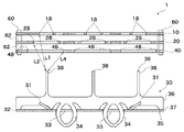
図1および図6を参照して、第3の電極30の構成について説明する。第3の電極30は、第1の電極10、第2の電極20および第4の電極40と対向して配置され、それらとの間にコロナ放電を生ずる電極である。第3の電極30は、第1の電極構造18、第2の電極構造28および第4の電極構造48の中心軸上に延在する棒状の第3の電極構造38を有する。第3の電極構造38の先端39、すなわち、第1の電極10、第2の電極20および第4の電極40側の近位端は、平面に形成される。ここでいう平面には、先端39の周縁に丸みや面取りが設けられ、あるいは、先端39が全体として滑らかな回転楕円形状(単軸回りの回転体)である場合を含む。
The configuration of the
第3の電極構造38の他端側(第1の電極10、第2の電極20および第4の電極40からの遠位端側)は、平板36で形成される。平板36は、横方向(図1における左右方向)に延在し、隣接する第3の電極構造38の平板36と一体に形成される。即ち、図1に示す第3の電極30では、1枚の平板36から3本の第3の電極構造38が突出する。図6には、1枚の平板36から2本の第3の電極構造38が突出するものも示される。第3の電極構造38の数量と配置は、第1の電極構造18、第2の電極構造28および第4の電極構造48の数量と配置に合わせて、適宜選択される。
The other end side of the third electrode structure 38 (the distal end side from the
第3の電極30の平板36は、第3の電極板32に固定され、立設される。第3の電極板32は、第1の電極10等と同様に導体板で形成され、第1の電極10等と平行に配置される。平板36は、第3の電極構造38の第1の電極10等からの遠位端37で第3の電極板32に当接する部分35を有する。さらに、平板36から遠位端37を超えて延在する第3の電極板32を貫通する部分34が形成される。電極板を貫通する部分34は、下が開いたC形あるいは円環形で部材の幅が狭く形成される。すなわち、C形あるいは円環形を弾性的に狭めることが可能である。ここで、第3の電極板32を貫通した部分にC形あるいは円環形の最大径(図1の左右方向)が来る。第3の電極板32には電極板を貫通する部分34が貫通する貫通穴33が形成される。貫通穴33の径(図1の左右方向)は、電極板を貫通する部分34の最大径と同じか僅かに狭い。よって、電極板を貫通する部分34が貫通穴33を貫通することにより、電極板を貫通する部分34の弾性で貫通穴33と嵌合するとともに、第3の電極板32を持ち上げる方向の力を生ずる。したがって、当接する部分35と電極板を貫通する部分34とで平板36が第3の電極板32を挟み、しっかりと固定される。
The
図6で示すように、第3の電極板32は、平板36に沿って折り曲げられた折り曲げ部分31を有する。折り曲げ部分31が平板36の両側に形成されることにより、平板36が面外方向に傾くことを防止する。このように、簡単な構造で第3の電極構造38および平板36は、第3の電極板32に固定される。なお、第3の電極板30の構造は上記の構造に限定されることはなく、平板36と第3の電極板32の固定も公知の方法でよい。
As shown in FIG. 6, the
なお、第1の電極10を第1の金属層とも称し、第1の空洞12を第1の空洞領域、第2の空洞14を第2の空洞領域、第1の導電体領域16を第1の金属領域とも称する。第2の電極20を第2の金属層とも称し、第3の空洞22を第3の空洞領域、第4の空洞24を第4の空洞領域、第2の導電体領域26を第2の金属領域とも称する。第3の電極構造38を第1及び第2の空洞パターンの中心軸に配置する電極と、あるいは、文脈上明らかな場合には単に電極とも称する。なお、第1の電極10、第2の電極20、第3の電極30等を、単に電極と称することもある。
The
図7に示すように、空気清浄機1は、第1の電極10、第2の電極20および第4の電極40と第3の電極30との距離を近接させ、また、離間させる第1・第2・第4電極移動手段70または第3電極移動手段75を有することが好ましい。第1・第2・第4電極移動手段70は、ソレノイドを用いて伸縮する軸を有する。第1・第2・第4電極移動手段70の軸の先端には、電極固定手段60と固着する梁72が固定され、軸の上下動により梁72を介して電極固定手段60が上下動する。第1・第2・第4電極移動手段70は、空気清浄機1のケース6に外側に固定支持され、梁72がケース6を貫通している。第1の電極10、第2の電極20および第4の電極40と第3の電極30との距離を近接させ、また、離間させることにより、空気清浄機1が発生するイオン風の量を調整できる。また、空気清浄機1の第1の電極10、第2の電極20および第4の電極40と第3の電極30とに印加する電圧を変えても、イオン風の量を調整することができる。印加する電圧を変える場合であっても、コロナ放電を生ずる電圧の範囲内であることが必要であるので、調整できる範囲には限界があり、また、変圧器のコストも高くなり、制御も難しい。電極間の距離を調整することにより、イオン風の量を調整すると、細かな調整が可能であり、好ましい。更に、電圧の変化と電極間の距離の変化とを併用することで、イオン風の量を電圧の変化により大きく調整し、電極間の距離の変化により細かく調整することができ、精度よく、変化の幅を広く調整することができる。
As shown in FIG. 7, in the
なお、第1・第2・第4電極移動手段70は、ソレノイドによる電磁力で軸を伸縮する構造には限られず、モータとかさ歯車の組み合わせ、軸にネジを形成して該ネジと螺合する雌ネジを回転する構造等、他の公知の構造で軸を伸縮してもよい。また、第1・第2・第4電極移動手段70の軸は、電極固定手段60を延長した一体の構造で、第1・第2・第4電極移動手段70はケース内で固定されてもよい。さらに、電極固定手段60を介さずに第1の電極10、第2の電極20および第4の電極40を移動させてもよい。例えば、第1の電極10、第2の電極20および第4の電極40の導電体の板との間にバネ等の弾性体と電磁力が作用するような電磁石とを有して、第1の電極10、第2の電極20および第4の電極40を移動させる等、公知の構造でよい。さらに、公知の構造で、第1の電極10、第2の電極20または第4の電極40を電極毎に移動させてもよい。なお、電極10、20、40を電極毎に移動させる場合には、スペーサ62が不要となる。また、第1・第2・第4電極移動手段70は、空気清浄機1のケース6に直接的に固定支持されてもよいし、他の構造を介して固定支持されてもよい。
The first, second, and fourth electrode moving means 70 is not limited to a structure in which the shaft is expanded and contracted by an electromagnetic force generated by a solenoid. A combination of a motor and a bevel gear, a screw is formed on the shaft, and the screw is screwed. The shaft may be expanded or contracted by another known structure such as a structure for rotating a female screw. Further, the shaft of the first, second, and fourth electrode moving means 70 has an integrated structure in which the electrode fixing means 60 is extended, and even if the first, second, and fourth electrode moving means 70 are fixed in the case. good. Further, the
第3電極移動手段75は、第1・第2・第4電極移動手段70と同様に、公知の構造でよいので、重複する説明は省略する。図7に示すように、第3電極移動手段75は、ケース6内に設置される。第1・第2・第4電極移動手段70と同様に、ケース6外に設置されてもよい。第3の電極30は、電極固定手段60で固定されていないので、第3電極移動手段75の軸を第3の電極板32に固定する。空気清浄機1は、第1・第2・第4電極移動手段70だけを有しても、第3電極移動手段75だけを有しても、第1・第2・第4電極移動手段70と第3電極移動手段75の両方を有してもよい。
Since the third electrode moving means 75 may have a known structure as in the first, second, and fourth electrode moving means 70, overlapping description will be omitted. As shown in FIG. 7, the third electrode moving means 75 is installed in the
さらに、空気清浄機1は、加温されることにより芳香を発するアロマ剤80を備えてもよい。電極固定手段60の上端に液体のアロマ剤80を保管する容器であるアロマ保管部85を備え、電極固定手段60の周囲に繊維質の円筒82を巻き付け、アロマ保管部85のアロマ剤80を毛細管現象により吸い出す。なお、円筒82は、電極10、20、40間のスペーサ62に囲われて配置されてもよいし、スペーサ62の周囲に配置されてもよいし、電極10、20、40間にスペーサ62の代わりに配置されてもよい。そして、繊維質を第1の電極10と第2の電極20との間で各電極構造18、28を外れた部分に配置し、円筒82と繋げることにより、アロマ剤80を含有させる。同様に第2の電極20と第4の電極40との間にも繊維質を配置する。空気清浄機1を稼働、すなわち、各電極10、20、30、40に電圧を印加することにより、電極10、20、30、40が昇温し、その影響で空気清浄機1内の繊維質に含有されたアロマ剤80は加温され、芳香を発する。アロマ剤80は、例えば第1の電極10上に載置しても、他の場所においてもよい。また、アロマ剤は、固体状のもの、天然木等であってもよく、その場合は各電極10、20、40上に直接載置すればよい。
Further, the
次に、空気清浄機1の作用について説明する。第1の電極10、第2の電極20および第4の電極40に負電圧を、第3の電極30に正電圧を印加することにより、第3の電極構造38と第1の電極構造18との間、第3の電極構造38と第2の電極構造28との間、第3の電極構造38と第4の電極構造48との間にコロナ放電を生じる。第1の電極10、第2の電極20および第4の電極40の電圧は、同じでよいが、異なっていてもよい。同じ電圧を印加する場合には、積層された第1の電極10、第2の電極20および第4の電極40に1つの端子を接続することになるので、構造が単純になる。
Next, the operation of the
コロナ放電により、第1の電極構造18、第2の電極構造28および第4の電極構造48から、第3の電極構造38から離れる方向(図1の上方向)のイオン風が形成される。すなわち、第1の電極構造18、第2の電極構造28および第4の電極構造48で空気が+イオン化されるので、正電圧を印加された第3の電極構造38から離れる方向にイオン風が生成される。第1の電極構造18、第2の電極構造28および第4の電極構造48、すなわち3か所でイオン風が形成されるので、大量のイオン風が流れることになる。なお、イオン風には低濃度のオゾンが含まれる。
Due to the corona discharge, an ion wind is formed from the
ここで、第1の電極構造18と第3の電極構造38との距離L1は、第2の電極構造28と第3の電極構造38との距離L2より長いのが好ましい。また、第4の電極構造48と第3の電極構造38の距離L4を、第2の電極構造28と第3の電極構造38との距離L2より短くするのが好ましい。小径の第1の電極構造18では密度の高いイオン風が、より大径の第2の電極構造28では、より密度の低いイオン風が、さらに大径の第4の電極構造48では、更に密度の低いイオン風が生成される。しかし、第3の電極構造38との距離が長いとコロナ放電も弱くなるので、生成されるイオン風は低密度になる。よって、L1>L2>L4とすることにより、全体として均等な密度のイオン風が生成され易い。特に、第1の電極構造18、第2の電極構造28および第4の電極構造48を、第3電極を中心として放物面上に配置することが好ましい。放物面上に配置されることで、密度の均一なイオン風が生成され易い。なお、距離L1、L2、L4は上記には限定されず、他の関係であっても、同じ距離であってもよい。
Here, the distance L1 between the
空気清浄機1では、第3の電極構造38と第1の電極構造18、第2の電極構造28、第4の電極構造48の組合せを、例えば7つ備えることにより、大量のイオン風を噴出することが可能になる。このように、空気清浄機1によれば、簡便な構造で、大量のイオン風が得られる。
The
これまでの説明では、空気清浄機1は第1の電極10、第2の電極20および第4の電極40を有していたが、第4の電極40を有していなくてもよい。その分、イオン風の量は少なくなるが、用途等によっては、十分なイオン風が得られる。また、第1の電極10、第2の電極20、第4の電極40に加え、第5の電極(不図示)、第6の電極(不図示)等を備えてもよい。加えられるこれらの電極は、第1の電極10、第2の電極20と同様に、略円環状の導電体領域を有して電極構造を複数有し、第1の電極構造18等と同軸になるように第1の電極10等と積層される。
In the description so far, the
次に図8を参照して、空気清浄機1を備える空気清浄機システム90について説明する。空気清浄機システム90は、空気清浄機1と、空気清浄機1が置かれた空間100の環境データを計測する計測器110と、計測器110で計測された環境データに基づき、空気清浄機1の稼働状態を制御する制御装置120とを備える。空気清浄機1が置かれた空間100とは、空気清浄機1が置かれた部屋、店舗、倉庫など、外部との空気の流通が制限された空間であるが、必ずしも壁で囲われている必要はない。
Next, the air purifier system 90 including the
環境データには、空間100内の臭気、雑菌数、オゾン濃度、PM2.5および花粉などの粒子状物質の濃度を含む。さらに、温度、湿度、風の強さや向きなどを含んでもよい。環境データを計測する計測器110は、いずれかの環境データを計測する計測器であればよい。空間100内には複数の計測器110が設置されてもよい。複数の計測器110は同じ環境データを異なる場所で計測するものであっても、異なる環境データを計測するものであってもよい。 The environmental data includes the odor, the number of germs, the ozone concentration, and the concentration of particulate matter such as PM2.5 and pollen in the space 100. Further, temperature, humidity, wind strength and direction, etc. may be included. The measuring instrument 110 for measuring environmental data may be any measuring instrument for measuring environmental data. A plurality of measuring instruments 110 may be installed in the space 100. The plurality of measuring instruments 110 may measure the same environmental data at different places or may measure different environmental data.
制御装置120は、計測器110で計測された環境データに基づき、空気清浄機1の稼働状態を制御できればよく、空間100内の空気清浄機1以外の機器等を制御する制御装置であっても、汎用のPCであってもよく、特に限定されない。
The control device 120 only needs to be able to control the operating state of the
空気清浄機1と制御装置120および計測器110と制御装置120の間の信号伝達は、有線で行っても、無線で行ってもよい。図8に示す空気清浄機システム90では、空気清浄機1を3つ備える。2つの空気清浄機1は無線通信装置2を介して無線で制御装置120と通信し、1つの空気清浄機1は有線で制御装置120と通信する。計測器110の1つは無線通信装置112を介して無線で制御装置120と通信し、計測器110の1つはケーブル114を介して有線で制御装置120と通信する。特に計測器110は無線通信を介して制御装置120と通信できると、設置場所の自由度が増し、適切な場所に容易に設置できるので、好ましい。なお、計測器110が無線通信装置112を内蔵してもよい。
The signal transmission between the
制御装置120は、インターネット等の公衆回線202を通じて外部システム200から環境データを受信し、空気清浄機1の稼働状態を制御してもよい。例えば、気象庁、あるいは、その他の機関から、PM2.5の飛散情報あるいは花粉という微量のアレルギ物質などの飛散情報を受信して、空気清浄機1の稼働状態を制御してもよい。また制御装置120は、空気清浄機1のタイマー機能として、時間により空気清浄機1をオン・オフする機能を有してもよい。
The control device 120 may receive environmental data from the external system 200 through a public line 202 such as the Internet and control the operating state of the
続いて、空気清浄機システム90の作用を説明する。空気清浄機システム90では、空気清浄機1が置かれた空間100内の環境データを計測器110で計測する。例えば、臭気や雑菌数を計測する。臭気が強い場合や雑菌数が多い場合には、空気清浄機1が発生するイオン風の量を増やして、脱臭力や殺菌力を強めることが好ましい。そこで、空気清浄機1の各電極10、20、30、40へ印加する電圧を高め、あるいは、第1の電極10、第2の電極20または第4の電極40と第3の電極30との間の距離を狭めることにより、発生するイオン風の量を増やす。逆に臭気が弱い場合や雑菌数が少ない場合には、印加する電圧を下げ、あるいは電極間の距離を広げて、発生するイオン風の量を減らす。このように、計測器110で計測される環境データに基づき空気清浄機1の稼働状態を制御することにより、無駄に空気清浄機1を稼働させることなく、その空間に居る人にとって快適なイオン風を発生し、快適な環境を提供することができる。
Subsequently, the operation of the air purifier system 90 will be described. In the air purifier system 90, the environmental data in the space 100 in which the
空間内で環境データが均一でない場合には、複数の空気清浄機1と複数の計測器110を備えることにより、より快適な環境を提供することができる。複数の計測器110により、異なる位置において異なる環境データを計測し、計測した環境データに基づいてその位置に適した稼働状態で空気清浄機1を稼働する。よって、空間100内で環境データが異なる場合であっても、いずれの場所でも快適な環境を提供することができる。例えば、広い空間100の場合や、空間100内に環境データを変化(悪化)させる要因がある場合などに、特に効果的である。なお、空気清浄機システム90は、1つだけの空気清浄機1を備えていても、1つだけの計測器110を備えていてもよい。
When the environmental data is not uniform in the space, a more comfortable environment can be provided by providing a plurality of
なお、空気清浄機1の各電極10、20、30、40へ印加する電圧は、制御装置120からの信号に基づき、変圧器(不図示)で増減してもよい。また、空気清浄機1が変圧器を内蔵しても、制御装置120が変圧器の機能を有していてもよい。
The voltage applied to each of the
また、計測器110でオゾン濃度を測定してもよい。オゾン濃度が高いと、空間100に居る人にとって、オゾン臭が気になることがあるので、オゾン濃度が高すぎる場合には、空気清浄機1が発生するイオン風の量を減らすことが好ましい。そこで、空気清浄機1の各電極10、20、30、40へ印加する電圧を下げ、あるいは、第1の電極10、第2の電極20または第4の電極40と第3の電極30との間の距離を広げることにより、発生するイオン風の量を減らす。このように、計測器110で計測される環境データに基づき空気清浄機1の稼働状態を制御することにより、オゾン濃度が高すぎてオゾン臭を感じさせることを防止して、その空間に居る人にとって快適なイオン風を発生し、快適な環境を提供することができる。
Further, the ozone concentration may be measured by the measuring instrument 110. If the ozone concentration is high, the ozone odor may be annoying to the person in the space 100. Therefore, if the ozone concentration is too high, it is preferable to reduce the amount of ion air generated by the
また、制御装置120は、公衆回線202を通じて外部システム200から環境データを受信し、空気清浄機1の稼働状態を制御できる。例えば、気象庁から受信したPM2.5の飛散情報によりPM2.5が大量に飛散することが予想される場合には、空気清浄機1が発生するイオン風の量を増やすことが好ましい。イオン風によりPM2.5が分解し消滅されるからである。そこで、空気清浄機1の各電極10、20、30、40へ印加する電圧を高め、あるいは、第1の電極10、第2の電極20または第4の電極40と第3の電極30との間の距離を狭めることにより、発生するイオン風の量を増やす。このように、公衆回線202を通じて受信する外部システム200からの環境データに基づき空気清浄機1の稼働状態を制御することにより、予想される環境の変化に対応してイオン風を発生させるので、その空間に居る人にとって快適なイオン風を発生し、快適な環境を提供することができる。同様に、気象庁から受信した花粉の飛散情報により花粉が大量に飛散することが予想される場合には、空気清浄機1が発生するイオン風の量を増やすことが好ましい。花粉などの微粉も、オゾンで容易に酸化され、質量が増加して落下し、飛散しなくなる。
Further, the control device 120 can receive environmental data from the external system 200 through the public line 202 and control the operating state of the
また、制御装置120は、空気清浄機1のタイマー機能を有するので、時間により空気清浄機1のオン・オフを切り替えることができる。例えば、空気清浄機システム90を店舗で使用する場合に、閉店後に空気清浄機1を稼働し開店中は停止することにより、顧客の居る店内にオゾン臭が漂うことを防止しつつ、店内の脱臭、殺菌等を行うことができる。
Further, since the control device 120 has a timer function of the
また、制御装置120は、計測器110で計測した環境データが所定の範囲を超えた場合にアラームを発してもよい。環境が悪化した空間100内に居る人や外に居る人に注意を喚起することができる。アラームは、例えば制御装置120がアラーム音を発しても、アラーム表示をしても、空間100の内部または外部のアラーム装置(不図示)にアラーム音を発したりアラーム表示をするように信号を送信しても、他の公知の方法でアラームを発してもよい。 Further, the control device 120 may issue an alarm when the environmental data measured by the measuring instrument 110 exceeds a predetermined range. It is possible to call attention to those who are inside or outside the space 100 where the environment has deteriorated. For the alarm, for example, regardless of whether the control device 120 emits an alarm sound or displays an alarm, a signal is transmitted so as to emit an alarm sound or display an alarm to an alarm device (not shown) inside or outside the space 100. Alternatively, the alarm may be issued by another known method.
空気清浄機システム90では、計測器110で空間の環境データを計測し、また、公衆回線202を通じて受信する外部システム200からの環境データに基づき、さらに、タイマー機能により、空気清浄機1のオン・オフおよび発生するイオン風の量などの空気清浄機1の稼働状態を制御するので、その空間に居る人にとって快適なイオン風を発生し、その空間に居る人にとって快適な環境を提供することができる。
In the air purifier system 90, the
環境データとしては、温度、湿度、風の強さと方向など、空間内の環境に影響を与え得る他のデータを用いてもよい。タイマー機能としては、オン・オフだけではなく、時間によりイオン風の量を変化させでも、あるいは、環境データに基づき要求されるイオン風の量が時間により変更させるような機能であってもよい。 As the environmental data, other data that may affect the environment in the space, such as temperature, humidity, wind strength and direction, may be used. The timer function may be not only on / off but also a function of changing the amount of ion air with time, or a function of changing the amount of ion air required based on environmental data with time.
1 空気清浄機
2 無線通信装置
6 ケース
10 第1の電極(第1の金属層)
12 第1の空洞(第1の空洞領域)
14 第2の空洞(第2の空洞領域)
14a、b、c 扇形空洞
14d、e、f 継ぎ部分
16 第1の導電体領域(第1の金属領域)
18 第1の電極構造
20 第2の電極(第2の金属層)
22 第3の空洞(第3の空洞領域)
24 第4の空洞(第4の空洞領域)
24a、b、c 扇形空洞
24d、e、f 継ぎ部分
26 第2の導電体領域(第2の金属領域)
28 第2の電極構造
30 第3の電極
31 折り曲げ部分
32 第3の電極板
33 貫通穴
34 電極板を貫通する部分
35 電極板に当接する部分
36 第3の電極構造の平板
37 第3の電極構造の遠位端
38 第3の電極構造(第1及び第2の空洞パターンの中心軸に配置する電極)
39 第3の電極構造の先端
40 第4の電極
42 第5の空洞
48 第4の電極構造
50 貫通孔
60 電極固定手段
62 スペーサ
70 (第1・第2・第4)電極移動手段
72 梁
75 (第3)電極移動手段
80 アロマ剤
82 繊維質の円筒
85 アロマ保管部
90 空気清浄機システム
100 空間
110 計測器
112 無線通信装置
114 空間内配線
120 制御装置
122 空気清浄機配線
200 外部システム
202 公衆回線
1
12 First cavity (first cavity area)
14 Second cavity (second cavity area)
14a, b, c Fan-shaped
18
22 Third cavity (third cavity area)
24 Fourth cavity (fourth cavity area)
24a, b, c Fan-shaped
28
39 Tip of
Claims (12)
平板状の第2の金属体であり、前記第1の空洞パターンと異なる第2の空洞パターンを有し、第2の電圧が供給され、前記第1の金属層と積層する第2の金属層と、
前記第1及び第2の電圧と異なる第3の電圧が供給され、前記第1及び第2の空洞パターンの中心軸に配置する電極と、
前記第1の金属層、前記第2の金属層、前記第1及び第2の空洞パターンの中心軸に配置する電極の少なくとも1つを動かす電極移動手段とを備え、
前記第1の空洞パターンは、前記中心軸を基準に第1及び第2の空洞領域を含み、
前記第1の金属層は、前記第1及び第2の空洞領域の間の第1の金属領域を含み、
前記第2の空洞パターンは、前記中心軸を基準に第3及び第4の空洞領域を含み、
前記第2の金属層は、前記第3及び第4の空洞領域の間の第2の金属領域を含み、
前記第1の金属層及び前記電極間、並びに前記第2の金属層及び前記電極間で、それぞれコロナ放電を発生し、イオン及びオゾンの風を発生する、空気清浄機と;
前記空気清浄機が置かれた空間の環境データを計測する計測器と;
前記計測器で計測された環境データに基づき、前記空気清浄機の稼働状態を制御する制御装置とを備え;
前記制御装置は、前記前記第1の金属層、前記第2の金属層、あるいは前記第1及び第2の空洞パターンの中心軸に配置する電極に印加する電圧を変えて発生するイオン及びオゾンの風の量を調整し、さらに前記電極移動手段により前記前記第1の金属層、前記第2の金属層、前記第1及び第2の空洞パターンの中心軸に配置する電極の少なくとも1つを動かして、前記第1の金属層と前記第1及び第2の空洞パターンの中心軸に配置する電極の間の距離または前記第2の金属層と前記第1及び第2の空洞パターンの中心軸に配置する電極の間の距離を変更することにより発生するイオン及びオゾンの風の量をより細かく調整し、該空気清浄機の稼働状態を制御する;
空気清浄機システム。 A first metal body having a flat plate-like first metal body, having a first cavity pattern, and being supplied with a first voltage.
A second metal layer which is a flat plate-shaped second metal body, has a second cavity pattern different from the first cavity pattern, is supplied with a second voltage, and is laminated with the first metal layer. When,
An electrode to which a third voltage different from the first and second voltages is supplied and arranged on the central axis of the first and second cavity patterns, and
The first metal layer, the second metal layer, and the electrode moving means for moving at least one of the electrodes arranged on the central axes of the first and second cavity patterns are provided.
The first cavity pattern includes first and second cavity regions relative to the central axis.
The first metal layer comprises a first metal region between the first and second cavity regions.
The second cavity pattern includes third and fourth cavity regions relative to the central axis.
The second metal layer comprises a second metal region between the third and fourth cavity regions.
With an air purifier that generates a corona discharge and generates ion and ozone winds between the first metal layer and the electrodes, and between the second metal layer and the electrodes, respectively;
With a measuring instrument that measures environmental data in the space where the air purifier is placed;
It is equipped with a control device that controls the operating state of the air purifier based on the environmental data measured by the measuring instrument;
The control device comprises ions and ozone generated by changing the voltage applied to the first metal layer, the second metal layer, or the electrodes arranged on the central axes of the first and second cavity patterns. The amount of wind is adjusted, and at least one of the electrodes arranged on the central axis of the first metal layer, the second metal layer, and the first and second cavity patterns is moved by the electrode moving means. The distance between the first metal layer and the electrodes arranged on the central axes of the first and second cavity patterns, or on the central axis of the second metal layer and the first and second cavity patterns. By changing the distance between the placed electrodes, the amount of ion and ozone air generated is finely adjusted to control the operating state of the air purifier;
Air purifier system.
導電体板に、前記第1の空洞より大径の略円形の第3の空洞と、該第3の空洞と同軸である略円環形の第4の空洞とが形成され、前記第3の空洞と前記第4の空洞との間に略円環形の第2の導電体領域を有する第2の電極構造を複数有し、前記第1の電極構造と前記第2の電極構造とが同軸となるように前記第1の電極と積層される第2の電極と、
前記第1の電極と前記第2の電極との間に空隙を設けて固定する電極固定手段と、
前記第1の電極構造と前記第2の電極構造の中心軸上で、前記第1の電極構造および前記第2の電極構造から離間した位置に延在する第3の電極構造であって、前記第1の電極構造、前記第2の電極構造、該第3の電極構造の順に配置される複数の第3の電極構造と、該複数の第3の電極構造における前記第2の電極構造からの遠位端を固定支持する第3の電極板とを有する、第3の電極と
前記第1の電極、前記第2の電極、前記第3の電極の少なくとも1つを動かす電極移動手段とを備え、
前記第1の電極と前記第2の電極に負電圧を印加し、前記第3の電極に正電圧を印加することにより、前記第1の電極構造と前記第3の電極構造並びに前記第2の電極構造と前記第3の電極構造との間でコロナ放電を発生して前記第1の電極構造および前記第2の電極構造から前記第3の電極構造と離間する方向へのイオン風を生ずる、空気清浄機と;
前記空気清浄機が置かれた空間の環境データを計測する計測器と;
前記計測器で計測された環境データに基づき、前記空気清浄機の稼働状態を制御する制御装置とを備え;
前記制御装置は、前記第1の電極、前記第2の電極、あるいは前記第3の電極に印加する電圧を変えて発生するイオン及びオゾンの風の量を調整し、さらに前記電極移動手段により前記第1の電極、前記第2の電極、前記第3の電極の少なくとも1つを動かして、前記第1の電極と前記第3の電極の間の距離または前記第2の電極と前記第3の電極の間の距離を変更することにより発生するイオン及びオゾンの風の量をより細かく調整し、該空気清浄機の稼働状態を制御する;
空気清浄機システム。 A substantially circular first cavity and a substantially annular second cavity coaxial with the first cavity are formed on the conductor plate, and between the first cavity and the second cavity. A first electrode having a plurality of first electrode structures having a substantially annular first conductor region,
A third cavity having a diameter larger than that of the first cavity and a substantially annular fourth cavity coaxial with the third cavity are formed on the conductor plate, and the third cavity is formed. And the fourth cavity have a plurality of second electrode structures having a substantially annular second conductor region, and the first electrode structure and the second electrode structure are coaxial with each other. With the second electrode laminated with the first electrode as described above,
An electrode fixing means for fixing a gap between the first electrode and the second electrode,
A third electrode structure extending at a position separated from the first electrode structure and the second electrode structure on the central axis of the first electrode structure and the second electrode structure. From the plurality of third electrode structures arranged in the order of the first electrode structure, the second electrode structure, the third electrode structure, and the second electrode structure in the plurality of third electrode structures. With a third electrode having a third electrode plate that fixedly supports the distal end
The electrode moving means for moving at least one of the first electrode, the second electrode, and the third electrode is provided.
By applying a negative voltage to the first electrode and the second electrode and applying a positive voltage to the third electrode, the first electrode structure, the third electrode structure, and the second electrode are used. A corona discharge is generated between the electrode structure and the third electrode structure to generate an ion wind in a direction away from the first electrode structure and the second electrode structure and the third electrode structure. With an air purifier;
With a measuring instrument that measures environmental data in the space where the air purifier is placed;
Based on said environmental data measured by the measuring instrument, e Bei a control device for controlling the operating state of the air cleaner;
The control device adjusts the amount of ion and ozone air generated by changing the voltage applied to the first electrode, the second electrode, or the third electrode, and further, the electrode moving means is used. By moving at least one of the first electrode, the second electrode, and the third electrode, the distance between the first electrode and the third electrode or the second electrode and the third electrode can be moved. The amount of ion and ozone air generated by changing the distance between the electrodes is finely adjusted to control the operating state of the air purifier;
Air purifier system.
請求項1または2に記載の空気清浄機システム。 The environmental data is at least one of odor, germ count, and ozone concentration;
The air purifier system according to claim 1 or 2.
請求項1ないし3のいずれか1項に記載の空気清浄機システム。 The control device receives data on the environment through a public line and controls the operating state of the air purifier based on the data on the environment;
The air purifier system according to any one of claims 1 to 3.
請求項1ないし4のいずれか1項に記載の空気清浄機システム。 The environmental data measured by the measuring instrument is transmitted to the control device via wireless communication;
The air purifier system according to any one of claims 1 to 4.
請求項1ないし5のいずれか1項に記載の空気清浄機システム。 The control device has a timer function of the air purifier;
The air purifier system according to any one of claims 1 to 5.
請求項1ないし6のいずれか1項に記載の空気清浄機システム。 The control device controls the operating state of the air purifier by adjusting the voltage sent to the air purifier;
The air purifier system according to any one of claims 1 to 6.
前記第4の電極に負電荷が印加される;
請求項2および請求項2に従属する請求項3ないし7のいずれか1項に記載の空気清浄機システム。 In the air purifier, a fifth cavity having a diameter larger than that of the third cavity is formed on the conductor plate, and a fourth electrode structure, which is a conductor region on the periphery of the fifth cavity, is formed. The first electrode is located between the second electrode and the third electrode so that the fourth electrode structure, the first electrode structure, and the second electrode structure are coaxial with each other. A fourth electrode laminated with the electrode and the second electrode, further comprising a fourth electrode fixed by the electrode fixing means.
A negative charge is applied to the fourth electrode;
The air purifier system according to any one of claims 3 to 7 , which is dependent on claim 2 and claim 2.
請求項8に記載の空気清浄機システム。 The air purifier controls the operating state of the air purifier by moving the fourth electrode and changing the distance between the fourth electrode and the third electrode;
The air purifier system according to claim 8.
請求項1ないし9のいずれか1項に記載の空気清浄機システム。 The control device issues an alarm when the environmental data exceeds a predetermined range;
The air purifier system according to any one of claims 1 to 9.
請求項1ないし10のいずれか1項に記載の空気清浄機システム。 The air purifier further comprises an aroma agent that emits an aroma when heated;
The air purifier system according to any one of claims 1 to 10.
請求項1ないし11のいずれか1項に記載の空気清浄機システム。 It is equipped with a plurality of the above-mentioned air purifiers;
The air purifier system according to any one of claims 1 to 11.
Priority Applications (5)
| Application Number | Priority Date | Filing Date | Title |
|---|---|---|---|
| JP2017179018A JP6982855B2 (en) | 2017-09-19 | 2017-09-19 | Air purifier system |
| CN201880055217.9A CN111052523B (en) | 2017-09-19 | 2018-07-24 | Air purifier system |
| PCT/JP2018/027732 WO2019058749A1 (en) | 2017-09-19 | 2018-07-24 | Air cleaner system |
| US16/641,427 US20210052765A1 (en) | 2017-09-19 | 2018-07-24 | Air cleaner system |
| KR1020207005392A KR20200055706A (en) | 2017-09-19 | 2018-07-24 | Air freshener system |
Applications Claiming Priority (1)
| Application Number | Priority Date | Filing Date | Title |
|---|---|---|---|
| JP2017179018A JP6982855B2 (en) | 2017-09-19 | 2017-09-19 | Air purifier system |
Publications (2)
| Publication Number | Publication Date |
|---|---|
| JP2019053957A JP2019053957A (en) | 2019-04-04 |
| JP6982855B2 true JP6982855B2 (en) | 2021-12-17 |
Family
ID=65810207
Family Applications (1)
| Application Number | Title | Priority Date | Filing Date |
|---|---|---|---|
| JP2017179018A Active JP6982855B2 (en) | 2017-09-19 | 2017-09-19 | Air purifier system |
Country Status (5)
| Country | Link |
|---|---|
| US (1) | US20210052765A1 (en) |
| JP (1) | JP6982855B2 (en) |
| KR (1) | KR20200055706A (en) |
| CN (1) | CN111052523B (en) |
| WO (1) | WO2019058749A1 (en) |
Families Citing this family (4)
| Publication number | Priority date | Publication date | Assignee | Title |
|---|---|---|---|---|
| KR102487542B1 (en) * | 2019-05-24 | 2023-01-11 | 주식회사 이서 | Device and method for managing fine particle concentration |
| KR102173407B1 (en) * | 2020-03-09 | 2020-11-03 | (주)파코코리아인더스 | Air purification system using corona discharge |
| TW202220320A (en) * | 2020-11-12 | 2022-05-16 | 日商夏普股份有限公司 | (無) |
| JP2023131885A (en) * | 2022-03-10 | 2023-09-22 | エクレール株式会社 | Split type ozone generator |
Family Cites Families (12)
| Publication number | Priority date | Publication date | Assignee | Title |
|---|---|---|---|---|
| SE9003156L (en) * | 1990-10-03 | 1992-04-04 | Astra Vent Ab | DEVICE FOR GENERATING AN AIR FLOW AND CLEANING THEM |
| JP3680121B2 (en) * | 2000-05-18 | 2005-08-10 | シャープ株式会社 | Sterilization method, ion generator and air conditioner |
| JP3242637B1 (en) * | 2001-11-26 | 2001-12-25 | 日本ぱちんこ部品株式会社 | Ion generator |
| JP3770547B2 (en) * | 2002-03-01 | 2006-04-26 | ヒューグルエレクトロニクス株式会社 | Ionizer control system |
| GB0229493D0 (en) * | 2002-12-18 | 2003-01-22 | Battelle Memorial Institute | Aroma dispensing device |
| JP2006288453A (en) * | 2005-04-06 | 2006-10-26 | Sanyo Electric Co Ltd | Air treatment device |
| JP2011010991A (en) * | 2009-07-06 | 2011-01-20 | Sharp Corp | Air purifier |
| JP2011067500A (en) * | 2009-09-28 | 2011-04-07 | Panasonic Corp | Vacuum cleaner |
| JP4551977B1 (en) * | 2010-01-26 | 2010-09-29 | 明夫 片野 | Ion / ozone wind generator |
| CN207084405U (en) * | 2014-06-20 | 2018-03-13 | 康奈尔公司 | Device for forming hair |
| JP6466866B2 (en) * | 2016-02-24 | 2019-02-06 | シャープ株式会社 | Ion delivery device |
| JP3210591U (en) * | 2017-03-07 | 2017-06-01 | エクレール株式会社 | Air cleaner |
-
2017
- 2017-09-19 JP JP2017179018A patent/JP6982855B2/en active Active
-
2018
- 2018-07-24 WO PCT/JP2018/027732 patent/WO2019058749A1/en active Application Filing
- 2018-07-24 US US16/641,427 patent/US20210052765A1/en not_active Abandoned
- 2018-07-24 KR KR1020207005392A patent/KR20200055706A/en not_active Application Discontinuation
- 2018-07-24 CN CN201880055217.9A patent/CN111052523B/en active Active
Also Published As
| Publication number | Publication date |
|---|---|
| CN111052523B (en) | 2021-09-07 |
| WO2019058749A1 (en) | 2019-03-28 |
| JP2019053957A (en) | 2019-04-04 |
| CN111052523A (en) | 2020-04-21 |
| KR20200055706A (en) | 2020-05-21 |
| US20210052765A1 (en) | 2021-02-25 |
Similar Documents
| Publication | Publication Date | Title |
|---|---|---|
| JP6982855B2 (en) | Air purifier system | |
| US8282028B2 (en) | Electrostatically atomizing device | |
| WO2007145058A1 (en) | Electrostatic atomizing apparatus | |
| US20070108310A1 (en) | Delivery system for dispensing volatile materials using an electromechanical transducer in combination with an air disturbance generator | |
| JP4462348B2 (en) | Ion generator and its ozone amount adjusting method | |
| ATE520469T1 (en) | ELECTROSTATIC ATOMIZER | |
| CH708342A1 (en) | Atomizer humidifier and Verneblermodul. | |
| CN102844052A (en) | Electrostatic atomizing device | |
| KR20200094066A (en) | Plasma generator using dielectric barrier discharge and air cleaning device comprising the same | |
| US10258922B2 (en) | Device for deodorization and disinfection | |
| JP5816808B2 (en) | Non-contact liquid detection device | |
| JP7065357B2 (en) | Mist generator | |
| US20150306411A1 (en) | Apparatus and method for treatment of organic human tissue with a low pressure plasma | |
| WO2022019251A1 (en) | Magnetic field generation device, magnetic field generation system, method for producing irradiated target object, irradiated target object, liquid, water, humidifier, humidification method, program, and computer-readable storage medium | |
| JP4774498B2 (en) | Negative ion generator | |
| JP2003100419A (en) | Ion generator and air conditioner | |
| JP3606864B2 (en) | Ion generator and air conditioner | |
| JP3117670U (en) | Electric shock insecticide | |
| JP2011036213A (en) | Device and method for raising plant | |
| KR20150094399A (en) | Sterilizer and method of controlling thereof | |
| KR100545564B1 (en) | A Tube type plasma anion generator | |
| JP5905339B2 (en) | Vibrating perforated plate unit and atomizing device | |
| CN109641223A (en) | Electrostatic atomizer | |
| KR102471749B1 (en) | Electric diffuser for aroma | |
| JP2003117433A (en) | Minus ion generation apparatus |
Legal Events
| Date | Code | Title | Description |
|---|---|---|---|
| A621 | Written request for application examination |
Free format text: JAPANESE INTERMEDIATE CODE: A621 Effective date: 20200826 |
|
| A131 | Notification of reasons for refusal |
Free format text: JAPANESE INTERMEDIATE CODE: A131 Effective date: 20210622 |
|
| A521 | Request for written amendment filed |
Free format text: JAPANESE INTERMEDIATE CODE: A523 Effective date: 20210820 |
|
| TRDD | Decision of grant or rejection written | ||
| A01 | Written decision to grant a patent or to grant a registration (utility model) |
Free format text: JAPANESE INTERMEDIATE CODE: A01 Effective date: 20211026 |
|
| A61 | First payment of annual fees (during grant procedure) |
Free format text: JAPANESE INTERMEDIATE CODE: A61 Effective date: 20211115 |
|
| R150 | Certificate of patent or registration of utility model |
Ref document number: 6982855 Country of ref document: JP Free format text: JAPANESE INTERMEDIATE CODE: R150 |