JP6982291B2 - Machine tool work processing method - Google Patents
Machine tool work processing method Download PDFInfo
- Publication number
- JP6982291B2 JP6982291B2 JP2017118343A JP2017118343A JP6982291B2 JP 6982291 B2 JP6982291 B2 JP 6982291B2 JP 2017118343 A JP2017118343 A JP 2017118343A JP 2017118343 A JP2017118343 A JP 2017118343A JP 6982291 B2 JP6982291 B2 JP 6982291B2
- Authority
- JP
- Japan
- Prior art keywords
- tool
- correction value
- corrected
- machining
- work
- Prior art date
- Legal status (The legal status is an assumption and is not a legal conclusion. Google has not performed a legal analysis and makes no representation as to the accuracy of the status listed.)
- Active
Links
Images


Description
この発明は、工作機械の熱変形に起因する加工誤差を補正してワークを加工する方法に関するもので、特に主軸台側の熱変形に基づく加工誤差をより正確に補正することが可能な加工方法に関するものである。 The present invention relates to a method of machining a workpiece by correcting a machining error caused by thermal deformation of a machine tool, and in particular, a machining method capable of more accurately correcting a machining error based on thermal deformation of the headstock side. It is about.
工作機械を運転すると、加工熱、モータや軸受部の発熱、作動油や切削液の温度上昇などにより、機械温度が上昇し、それに伴う工作機械各部の熱変形がワークの加工精度を低下させる。そこで工作機械の各部の温度を計測し、そのとき加工されたワークの加工誤差を計測することにより、機械各部の温度と加工誤差の関係を求めて、加工プログラムの指令値を補正する演算式ないし演算テーブルを作成し、これを制御器に登録して、加工プログラムの指令値を補正することにより、加工誤差が生じないようにしている。 When a machine tool is operated, the machine temperature rises due to machining heat, heat generation of motors and bearings, temperature rise of hydraulic oil and cutting fluid, etc., and the accompanying thermal deformation of each part of the machine tool lowers the machining accuracy of the workpiece. Therefore, by measuring the temperature of each part of the machine tool and measuring the machining error of the workpiece machined at that time, the relationship between the temperature of each part of the machine and the machining error is obtained, and the command value of the machining program is corrected. By creating a calculation table, registering it in the controller, and correcting the command value of the machining program, machining errors are prevented from occurring.
工作機械の熱変形量は、温度に比例すると見做してよいので、一般的には図1に示すように、工作機械のベッド11、主軸台12、刃物台3の要所要所に温度センサs1、s2・・・snを取付け、各センサの検出値t1、t2・・・tnに乗ずる係数α1、α2・・・αnと定数βとを試験加工により決定して、補正値δを次式(以下、「従来式」と言う。)
δ=α1t1+α2t2+・・・αntn+β
で演算するというような方法が採用されている。
Since the amount of thermal deformation of the machine tool can be considered to be proportional to the temperature, generally, as shown in FIG. 1, temperature sensors are placed at key points of the
δ = α1t1 + α2t2 + ・ ・ ・ αntn + β
A method such as calculating with is adopted.
工作機械は、ワークを3次元形状に加工するので、上記の補正値δも3次元の各軸方向の補正値として演算される。例えば旋盤であれば、主軸方向であるZ軸方向、工具の切り込み送り方向であるX軸方向の補正値が演算され、回転工具をY軸方向にも移動させる旋盤では、Y軸方向の補正値も演算される。また、上記の演算式における係数αや定数βは刃物台の位置により異なる値となるので、例えば旋盤であれば、係数αと定数βを刃物台の位置の関数として設定するか、あるいは複数箇所における値を設定してその中間位置での補正値は両側の補正値から補間演算で求めるというようにして、刃物台の位置に応じた補正値を定めている。 Since the machine tool processes the work into a three-dimensional shape, the above-mentioned correction value δ is also calculated as a correction value in each of the three-dimensional axial directions. For example, in the case of a lathe, the correction value in the Z-axis direction, which is the main axis direction, and the correction value in the X-axis direction, which is the cutting feed direction of the tool, are calculated. Is also calculated. Further, since the coefficient α and the constant β in the above calculation formula have different values depending on the position of the tool post, for example, in the case of a lathe, the coefficient α and the constant β are set as a function of the position of the tool post, or at a plurality of locations. The correction value at the intermediate position is determined by the interpolation calculation from the correction values on both sides, and the correction value according to the position of the tool post is determined.
上記のような演算による補正値の精度を高める手段として、例えば特許文献1では、所定の時間間隔毎に演算した補正値δの値と前回の補正値δfの値との差が予め登録した隣接設定値を超えているときは、前回補正値δfに隣接設定値を加えた値を補正値とすること、最大値δmaxと最小値δminとを登録しておき、演算した補正値δが当該最大値より大きいか又は最小値より小さいときは、当該最大値又は最小値を補正値とすることが提案されている。
As a means for improving the accuracy of the correction value by the above calculation, for example, in
また特許文献2には、環境温度の変化に基づく補正量を演算するための係数と環境温度がワークの加工誤差として影響する際の時間差とを予め制御器に登録しておいて、加工時に計測された機械各部の温度と、加工時から時間差だけ隔たった時刻における環境温度とにより補正値を演算することが提案されている。
Further, in
機械を熱変形させる主な熱源は、主軸や回転工具軸のモータ及び軸受、油圧シリンダなどの油圧機器及びワークの加工部である。ワークの加工部で発生した熱は、加工部から流下する切削油によってベッドやテーブルに伝えられる。主要な熱源の位置は、工作機械の種類によって異なり、例えば旋盤であれば、主軸軸受、刃物台に搭載されている工具モータや油圧装置及び加工部である。加工部から流下する切削油は、通常はベッド上面に設けられているカバーの上に流下し、このカバーが加熱されることによってその内側にあるベッド上面が間接的に加熱される。 The main heat sources that thermally deform machines are the machining parts of hydraulic equipment and workpieces such as motors and bearings for spindles and rotary tool shafts, and hydraulic cylinders. The heat generated in the machined part of the work is transferred to the bed or table by the cutting oil flowing down from the machined part. The position of the main heat source differs depending on the type of machine tool. For example, in the case of a lathe, it is a spindle bearing, a tool motor mounted on a tool post, a hydraulic device, and a machining part. The cutting oil flowing down from the processed portion usually flows down onto a cover provided on the upper surface of the bed, and by heating this cover, the upper surface of the bed inside the cover is indirectly heated.
機械の熱変形を計測するために設けられるセンサは、主軸台、ベッド、刃物台などの機械部材の表面に取り付けられている。一方、主軸軸受やタレット刃物台のインデックス装置に設けられている油圧装置の熱は、機械の内部で発生する。そのため、機械内部で発生した熱が機械表面のセンサで検出されるまでに時間遅れが生ずる。機械内部の温度変化が熱伝達の遅れのためにセンサで検出されなくても、機械内部では熱変形が起こっており、その変形は、時間遅れを生ずることなく、機械全体に影響を与えるので、上述したような従来の方法では、機械内部の発熱の変化がセンサで検出されるまでの時間遅れによる熱変形の誤差を補正することはできない。 A sensor provided for measuring thermal deformation of a machine is attached to the surface of a mechanical member such as a headstock, a bed, and a tool post. On the other hand, the heat of the hydraulic device provided in the index device of the spindle bearing and the turret tool post is generated inside the machine. Therefore, there is a time delay before the heat generated inside the machine is detected by the sensor on the surface of the machine. Even if the temperature change inside the machine is not detected by the sensor due to the delay in heat transfer, thermal deformation occurs inside the machine, and the deformation affects the entire machine without causing a time delay. With the conventional method as described above, it is not possible to correct the error of thermal deformation due to the time delay until the change in heat generation inside the machine is detected by the sensor.
主軸が常時回転している旋削のみを行う旋盤では、主軸軸受の温度上昇に大きな変動はないと考えられる。しかし、主軸を停止した状態で刃物台に取り付けた回転工具でワークを加工することのできる、いわゆる複合旋盤では、1個のワークの加工中に主軸が回転したり、停止したりするので、主軸軸受で発生する熱が急激に変動するということが頻繁に起こる。従って、刃物台に回転工具を装着した複合旋盤では、主軸軸受が熱源となって主軸台を熱変形させる熱変形誤差の補正を従来手段では十分に補正することができない。 It is considered that there is no significant change in the temperature rise of the spindle bearing in a lathe that only performs turning in which the spindle is constantly rotating. However, in a so-called compound lathe that can machine a workpiece with a rotary tool attached to the tool post with the spindle stopped, the spindle rotates or stops during the machining of one workpiece, so the spindle Frequently, the heat generated by the bearings fluctuates rapidly. Therefore, in a compound lathe in which a rotary tool is mounted on a tool post, the conventional means cannot sufficiently correct the correction of the thermal deformation error in which the spindle bearing serves as a heat source and the spindle is thermally deformed.
この発明は、伝熱遅れによって機械内部の温度変化が機械に設けた温度センサで検出されるまでの時間遅れに起因する加工誤差を補正することが可能なワークの加工方法を提供することを課題としている。 It is an object of the present invention to provide a machining method for a workpiece capable of correcting a machining error caused by a time delay until a temperature change inside the machine is detected by a temperature sensor provided in the machine due to a heat transfer delay. It is supposed to be.
ワークの仕上げ加工用の工具が割り出されたとき又は予め定めたタイミングで、主軸1を予め定めた任意の位相に固定し、当該主軸に装着したチャック2又はワークwの周面に工具Tの刃先を接触させる。接触させる工具Tは、次の加工を行うために割り出された工具であり、仕上げ工具であることが望ましい。
When the tool for finishing the work is indexed or at a predetermined timing, the
接触の検出は、工具Tを装着した刃物台3の送りモータ4xのサーボ電流値の変化により検知するのが好ましく、接触させる工具Tの刃先に損傷を与えない力(数N)で送りモータ4xの負荷変動を検知し、接触が検知されたときの刃物台3の座標(旋盤ではX座標又はX−Y座標)を記憶する。刃先を接触させるZ軸方向の位置は、予め定めた2位置A、Bとする。
The contact is preferably detected by the change in the servo current value of the
接触を検出したときの刃物台3の座標を、従来手段のみで補正したときの座標、より実用的には、前回計測したときの座標と比較して修正することで、熱変形を正確に補正することができ、計測するときの動作を予め制御器6に登録しておくことにより、自動的に補正値を更新する。
Accurately correct the thermal deformation by correcting the coordinates of the
例えばこの発明での熱変形の補正値δは、
δ=α1t1+α2t2+α3t3+・・・+αntn+β+γ+εSのような式で演算される。ここで、γは主軸の変位を計測して設定される補正項、εは主軸の傾斜角を計測して設定される補正係数、Sは計測位置(A又はB)から加工位置PまでのZ軸方向の距離である。γ及びεは、ワーク加工中の所定のタイミングで逐次更新される。
For example, the correction value δ for thermal deformation in the present invention is
It is calculated by an expression such as δ = α1t1 + α2t2 + α3t3 + ... + αntn + β + γ + εS. Here, γ is a correction term set by measuring the displacement of the spindle, ε is a correction coefficient set by measuring the inclination angle of the spindle, and S is Z from the measurement position (A or B) to the machining position P. Axial distance. γ and ε are sequentially updated at predetermined timings during workpiece processing.
この発明のワーク加工方法は、機械各部の温度を温度センサs1、s2・・・snで計測して機械の熱変形を間接的に計測して補正する従来方法に加えて、機械の変位を直接計測して従来方法で補正したときと実際の変位と差(ずれ)を求めて補正値を修正する。 The work processing method of the present invention directly measures the displacement of the machine in addition to the conventional method of measuring the temperature of each part of the machine with temperature sensors s1, s2 ... Sn and indirectly measuring and correcting the thermal deformation of the machine. Correct the correction value by finding the difference (deviation) from the actual displacement when measured and corrected by the conventional method.
工具Tの刃先を接触させる位置は、主軸方向に所定距離離れた2位置A、Bとすることで、位置ずれと傾きのずれを検出することができ、位置を検出した位置A、Bと加工位置Pとが離れている場合の補正値の修正をより正確に行うことができる。工具の刃先をワークwの周面に接触させて修正値を求める方法では、ワークと工具の刃先との硬度の差により、ワークwが傷つくが、ずれの検出は、ワークwの仕上げ加工の前に行われるので、当該傷は、仕上げ加工で除去できる。ワークの一部に高精度加工が指定されているときは、当該指定された位置でずれを検出すればよい。 By setting the positions where the cutting edge of the tool T comes into contact with the two positions A and B separated by a predetermined distance in the spindle direction, it is possible to detect the positional deviation and the tilt deviation, and the positions A and B where the positions are detected are processed. It is possible to more accurately correct the correction value when the position P is far from the position P. In the method of contacting the cutting edge of the tool with the peripheral surface of the work w to obtain the correction value, the work w is damaged due to the difference in hardness between the work and the cutting edge of the tool, but the deviation is detected before the finishing process of the work w. The scratches can be removed by finishing. When high-precision machining is specified for a part of the work, the deviation may be detected at the specified position.
この発明では、機械表面の温度を用いて間接的に熱変形を補正するだけでなく、間接的に補正した熱変形を更に所定間隔毎に逐次更新される実際の変形に基づく修正を加えて補正するので、機械内部の急激な温度変化にも対応した補正が可能である。そして、切削工具を使って刃先の位置をチャックやワークに接触して補正値を逐次修正するので、ツールセッターを使う必要がなく、機械を止める必要がなく、連続加工中でも正確な加工寸法の補正が可能になる。 In the present invention, not only the temperature of the machine surface is used to indirectly correct the thermal deformation, but also the indirectly corrected thermal deformation is further corrected by making corrections based on the actual deformations that are sequentially updated at predetermined intervals. Therefore, it is possible to make corrections corresponding to sudden temperature changes inside the machine. Then, using a cutting tool, the position of the cutting edge is contacted with the chuck or workpiece to sequentially correct the correction value, so there is no need to use a toolsetter, there is no need to stop the machine, and accurate machining dimension correction is performed even during continuous machining. Will be possible.
更に、新たに計測装置を用意する必要がなく、測定を短時間でかつ自動で行うことができるので、加工サイクルに及ぼす影響は小さく、無人運転中でも必要な補正を逐次行わせることができる。 Further, since it is not necessary to prepare a new measuring device and the measurement can be performed automatically in a short time, the influence on the machining cycle is small, and the necessary correction can be sequentially performed even during unmanned operation.
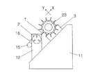
以下、図面を参照して、この発明を更に説明する。図1及び図2は、最も簡単な構造のスラント型のタレット旋盤を模式的に示した図である。スラント型の旋盤は、上面が傾斜したベッド11を備えている。主軸台12は、ベッド11から垂直に立ち上がっており、その上部に図に点線で示す主軸軸受13で主軸1が軸支されている。主軸1の先端には、チャック2が取り付けられ、後端にはチャック開閉シリンダ14が取り付けられている。主軸を回転する主軸モータ15は、主軸台12に取り付けられており、主軸モータ15の回転軸と主軸1は、同期ベルト装置16で連結されている。
Hereinafter, the present invention will be further described with reference to the drawings. 1 and 2 are diagrams schematically showing a slant-type turret lathe having the simplest structure. The slant-type lathe comprises a
スラント型旋盤の主軸1は、主軸台12のベッド11からの図2における左右の立ち上がり高さの差や主軸モータ15の発熱により、X軸方向に変位する傾向があり、Z軸方向の温度のアンバランスによる熱変形で、X軸に対して斜めになることがある(図4及び図6の一点鎖線d1及び二点鎖線d2参照)。
The
刃物台3は、ベッド11上にZ軸方向(主軸軸線方向)に移動自在な横移動台21にX軸方向(工具の切込み送り方向)に移動自在に設けられている。横移動台21は、Z軸送りモータ4zで正逆回転するZ軸送りねじ26zに螺合している。刃物台3は、横移動台21に搭載されたX軸モータ4xで正逆回転されるX軸送りねじ26xに螺合している。刃物台3には、割出装置22を介してタレット23が搭載されている。割出装置22は、タレット23の割出位置を固定する油圧装置を内蔵しており、タレットの割出回転用のモータ24と、タレットに取り付けた回転工具を駆動する工具モータ25とを備えている。
The
Z軸送りモータ4z及びX軸送りモータ4xは、サーボアンプ5z、5xを介して制御器6で制御されている。制御器6は、加工プログラム31に基づいてサーボアンプ5z、5xにそれぞれのモータに対する位置指令ez、exを出力している。一方、送りモータ4z、4xからは、フィードバック信号fz、fxがサーボアンプ5z、5xに返されている。X軸送りモータ4xの指令信号exとフィードバック信号fxとの差信号である位置偏差cが接触検出器7に与えられている。接触検出器7は、位置偏差cが予め設定された設定値を越えたときに、接触信号hを制御器6に送る。接触信号hを受けたとき、制御器6は、X軸送りモータ4xに停止指令iを送って直ちに停止させる。位置偏差cを検出するサーボアンプ5xは、0.1ミリ秒台の時間間隔で位置偏差を検出できるものを用いるのが望ましい。
The Z-
ベッド11、主軸台12及び刃物台3の適宜箇所には、温度センサs1、s2・・・snが取り付けられており、制御器6は、これらの温度センサの検出値t1、t2・・・tnに基づいて補正値を演算する補正手段32を備えている。
Temperature sensors s1, s2 ... Sn are attached to the
機械が運転されると、各部の熱源からの熱によって機械に熱変形が生じる。機械各部の温度は、温度センサs1、s2・・・snで検出され、これらの温度センサの検出温度に基づく熱変形の補正値δの演算式が補正手段32に登録されている。理解を容易にするため、図1では補正手段32に従来と同様な演算式
δx=αx1t1+αx2t2+αx3t3+・・・+αxntn+βx
が登録されているとして説明する。高い精度を必要としないワークの加工や粗加工は、加工プログラム31で指定された指定値を上式に基づいて計算された補正値δz、δxで補正して各モータ4z、4xの位置指令ez、exとする。
When the machine is operated, the heat from the heat source of each part causes thermal deformation of the machine. The temperature of each part of the machine is detected by the temperature sensors s1, s2 ... Sn, and the calculation formula of the thermal deformation correction value δ based on the detected temperature of these temperature sensors is registered in the correction means 32. In order to facilitate understanding, in FIG. 1, the correction means 32 has the same arithmetic expression as the conventional one δx = αx1t1 + αx2t2 + αx3t3 + ・ ・ ・ + αxntn + βx
Is explained as being registered. For machining and rough machining of workpieces that do not require high accuracy, the specified values specified in the
図1の補正手段32によって補正された後の、すなわち従来方法によって補正された後の刃物台3から見た主軸台12、チャック2及びワークwの位置は、例えば図4、6に一点鎖線d1で示すようになる。すなわち、ワークwの加工点pを加工するときの従来方法で補正された後の工具刃先の位置は点p1の位置となり、工具刃先を点p1に設定することにより、ワークの点pの加工が行われるとしている。なお、図6の点p1の位置は、次工程の加工が行われる前の位置である。製品の外周はこの位置から例えば仕上げ代だけ切除された位置となる。また、計測位置A、Bでのワークの径は同一である必要はない。
The positions of the
しかし前述したような理由により、従来の演算式による補正手段32の補正演算のみでは、熱変形を完全に補正することはできない。すなわち、刃物台から見た実際の主軸台、チャック及びワークの位置は、例えば図4、6に二点鎖線d2で示すように、補正手段32が演算した一点鎖線d1との間にずれがある。このずれΔa及びΔbは、補正手段32で補正された値から更にX軸方向に補正(修正)すべきずれである。なお、図4、6にはΔa、Δbとδa、δbとを略等しい間隔で示しているが、実際にはΔa、Δbはδa、δbより小さい。 However, for the reason described above, the thermal deformation cannot be completely corrected only by the correction calculation of the correction means 32 by the conventional calculation formula. That is, the positions of the actual spindle, chuck, and workpiece as seen from the tool post have a deviation from the one-dot chain line d1 calculated by the correction means 32, as shown by, for example, the two-dot chain line d2 in FIGS. .. The deviations Δa and Δb are deviations to be further corrected (corrected) in the X-axis direction from the values corrected by the correction means 32. Although Δa and Δb and δa and δb are shown at substantially equal intervals in FIGS. 4 and 6, in reality, Δa and Δb are smaller than δa and δb.
制御器6は、予め定めた主軸の位相、例えば原点位相と、チャック2又はワークwの周面の予め定めた2箇所のZ軸位置A、B(図3、5参照)とを設定する設定器を備えた計測動作設定手段33と、補正手段32で補正された補正値を更に補正(修正)する修正手段34とを備えている。
The
機械の熱変形の補正をより正確に行う必要があるのは、仕上げ加工のときである。計測動作設定手段33は、仕上げ加工用の工具Tが割り出されたとき、又は加工中の予め定めたタイミングで、主軸1を設定された位相に固定し、そのとき割り出されている工具の刃先を設定されたZ軸位置A、Bの一方Aに移動して、工具刃先を当該位置でチャック2又はワークwの外周に向けて低速接近させる。この低速接近中に位置偏差cが設定値を越えたときに接触検出器7が接触信号を出力する。このとき検出された刃物台の位置は、補正手段32で補正された後の工具刃先がチャック2又はワークwに接触するはずの位置からΔa及びΔbだけずれている。接触信号hを受けた計測動作設定手段33は、X送りモータ4xを停止し、そのときの刃物台3のX座標(点a2のX座標)と補正手段32で補正した後の当該計測位置におけるX座標の指令値(点a1のX座標)との差Δxaを演算して記憶する。
It is during finishing that it is necessary to more accurately correct the thermal deformation of the machine. The measurement operation setting means 33 fixes the
計測動作設定手段33は、次に工具刃先をX軸方向に後退させた後、他方の計測位置Bに移動し、同様な操作で刃物台3のX座標(点b2のX座標)と補正手段32で補正した後のX座標の指令値(点b1のX座標)との差Δxbを演算して記憶する。 The measurement operation setting means 33 then retracts the tool cutting edge in the X-axis direction, then moves to the other measurement position B, and performs the same operation as the X coordinate of the tool post 3 (X coordinate of the point b2) and the correction means. The difference Δxb from the command value of the X coordinate (X coordinate of the point b1) after the correction in 32 is calculated and stored.
修正手段34は、検出したX軸方向のずれγ=Δxaと、主軸の傾斜角(Δxa−Δxb)/Lにγとした計測位置(図の例ではA位置)からワークの加工位置Pまでの距離Sを乗じた値とで、加工位置Pにおけるx軸方向の修正値を
γ+εS=Δxa+(Δxa−Δxb)S/L
で演算する。
The correction means 34 is from the detected deviation γ = Δxa in the X-axis direction and the measurement position (position A in the example of the figure) where the inclination angle of the main axis (Δxa−Δxb) / L is γ to the machining position P of the work. With the value multiplied by the distance S, the correction value in the x-axis direction at the machining position P is γ + εS = Δxa + (Δxa−Δxb) S / L.
Calculate with.
上記の動作において、工具刃先をチャック周面に接近させる方向は、水平方向が最も良いが、スラント型の場合には、上方から下方へ移動させるようにして接近させる。これはX軸モータ4xに作用する送り負荷と刃物台の重量との関係で工具刃先とチャック周面との接触がより速やかに検出されるからである。
In the above operation, the direction in which the tool cutting edge is brought closer to the peripheral surface of the chuck is best in the horizontal direction, but in the case of the slant type, the tool cutting edge is moved from above to below. This is because the contact between the tool cutting edge and the peripheral surface of the chuck is detected more quickly due to the relationship between the feed load acting on the
その後の加工においては、加工プログラムの指定値を補正手段32に設定された演算式と修正手段34に設定された修正値とで補正して、x軸送りモータ4xに与える位置指令exとする。そして、次に仕上げ用の工具が割り出されたとき、又は設定されたタイミングが来たときに、同様な動作で修正手段34の設定値を変更してワークの自動連続加工を行う。
In the subsequent machining, the designated value of the machining program is corrected by the arithmetic expression set in the correction means 32 and the correction value set in the correction means 34, and the position command ex is given to the
上記の説明では、理解を容易にするために、補正手段32で従来方法による補正値を演算し、修正手段34で本願発明による修正値を演算して、両者を加えて指令値を補正すると説明したが、補正手段32に修正値を付加した演算式を登録しておくのがより実用的である。この場合の補正手段32に登録する演算式は、
δx=αx1t1+αx2t2+αx3t3+・・・+αxntn+βx+Δx+(Δxa−Δxb)×S/L
となる。そしてこの場合には、図4及び図6のδa、δbは上式で演算したδの値、Δa、Δbは、図4、6に括弧書きで示すように、前回計測時のΔaf、Δbfの値と今回計測時のΔag、Δbgの値との差となるので、修正手段34は、この差を演算して補正手段32に登録されているδを求める演算式のγとεを更新するという動作になる(図7参照)。
In the above description, in order to facilitate understanding, it is described that the correction means 32 calculates the correction value by the conventional method, the correction means 34 calculates the correction value according to the present invention, and the correction means 34 adds both to correct the command value. However, it is more practical to register the arithmetic expression with the correction value added to the correction means 32. The arithmetic expression registered in the correction means 32 in this case is
δx = αx1t1 + αx2t2 + αx3t3 + ・ ・ ・ + αxntn + βx + Δx + (Δxa−Δxb) × S / L
Will be. In this case, δa and δb in FIGS. 4 and 6 are the values of δ calculated by the above equation, and Δa and Δb are the values of Δaf and Δbf at the time of the previous measurement as shown in parentheses in FIGS. 4 and 6. Since it is the difference between the value and the values of Δag and Δbg at the time of this measurement, the correction means 34 calculates this difference and updates γ and ε of the calculation formula for obtaining δ registered in the correction means 32. It works (see Fig. 7).
上式は刃物台3側の熱変形誤差が補正手段32で演算された補正値で正しく補正されていると仮定した場合の幾何学的な演算に基づく補正値であるが、実際には上記のような考え方を基準として実際にワークを加工したときの寸法誤差を計測することにより、γ及びεに必要な係数を乗ずる等して、より正確な補正を行うことができるようにすべきである。
The above equation is a correction value based on a geometric calculation assuming that the thermal deformation error on the
なお、刃物台3がY軸方向にも移動する旋盤であれば、上述したX軸方向の検出動作と同様な検査をY軸方向にも行って、Y軸方向の修正値を演算する。また、旋盤が2主軸対向旋盤で、長尺ワークの両端を対向するチャックで把持して加工を行うときは、左右L−Rの主軸の補正手段32で補正した後の位置からのずれγL、γRとεL、εRをそれぞれ検出し、X軸方向のずれは両端のX方向のずれΔxL、ΔxRを加工点の位置で補間した量であるとし、主軸の傾斜によるずれは、例えば機械力学の便覧などで周知の両端支持梁の演算式で両端の位置ずれと傾斜角のずれからワークの加工点における撓み量を演算して補正すればよい。
If the
1 主軸
2 チャック
3 刃物台
4x 送りモータ
6 制御器
T 工具
w ワーク
1
Claims (2)
仕上げ工程などの精度の高い加工工程が開始されるとき又は予め制御器に登録した所定のタイミングで、主軸を所定の位相で停止し、当該工作機械の刃物台に装着された工具の刃先を予め定めた主軸軸線方向に所定距離離れた2箇所の計測位置で主軸チャックの周面又は当該主軸チャックに把持されたワークの周面に向けて低速で送り、それぞれの計測位置で送りモータの負荷が設定された負荷に達したときに当該送りモータを停止してそのときの刃物台の座標と当該工具刃先が前記計測位置に位置するときの刃物台のあるべき位置との差に基づく修正値で補正値を修正し、次の計測タイミングまでの間、当該修正された補正値で刃物台の位置を補正して加工を行うことを特徴とする、工作機械のワーク加工方法。 In the work machining method of a machine tool equipped with a means for correcting machining errors due to thermal deformation due to temperature changes.
At a predetermined timing registered when or pre controller precise machining process, such as the finishing step is started, to stop the main shaft at a predetermined phase, advance a cutting edge of the tool attached to the tool rest of the machine tool It feeds at low speed toward the peripheral surface of the spindle chuck or the peripheral surface of the work gripped by the spindle chuck at two measurement positions separated by a predetermined distance in the specified spindle axis direction, and the load of the feed motor is applied at each measurement position. When the set load is reached, the feed motor is stopped and the correction value is based on the difference between the coordinates of the turret at that time and the position where the turret should be when the tool cutting edge is located at the measurement position. A machine tool work machining method characterized in that the correction value is corrected and the position of the tool post is corrected by the corrected correction value until the next measurement timing.
Priority Applications (1)
| Application Number | Priority Date | Filing Date | Title |
|---|---|---|---|
| JP2017118343A JP6982291B2 (en) | 2017-06-16 | 2017-06-16 | Machine tool work processing method |
Applications Claiming Priority (1)
| Application Number | Priority Date | Filing Date | Title |
|---|---|---|---|
| JP2017118343A JP6982291B2 (en) | 2017-06-16 | 2017-06-16 | Machine tool work processing method |
Publications (3)
| Publication Number | Publication Date |
|---|---|
| JP2019000945A JP2019000945A (en) | 2019-01-10 |
| JP2019000945A5 JP2019000945A5 (en) | 2019-07-25 |
| JP6982291B2 true JP6982291B2 (en) | 2021-12-17 |
Family
ID=65005328
Family Applications (1)
| Application Number | Title | Priority Date | Filing Date |
|---|---|---|---|
| JP2017118343A Active JP6982291B2 (en) | 2017-06-16 | 2017-06-16 | Machine tool work processing method |
Country Status (1)
| Country | Link |
|---|---|
| JP (1) | JP6982291B2 (en) |
Families Citing this family (8)
| Publication number | Priority date | Publication date | Assignee | Title |
|---|---|---|---|---|
| JP6913920B2 (en) * | 2017-07-05 | 2021-08-04 | 中村留精密工業株式会社 | Machine tool work processing method |
| WO2020174585A1 (en) * | 2019-02-26 | 2020-09-03 | 国立大学法人東海国立大学機構 | Cutting device and contact position identification program |
| JP7309563B2 (en) * | 2019-10-17 | 2023-07-18 | シチズン時計株式会社 | Machine Tools |
| JP7074381B2 (en) * | 2021-03-18 | 2022-05-24 | 国立大学法人東海国立大学機構 | Cutting equipment |
| CN113126566B (en) * | 2021-06-18 | 2021-08-24 | 四川大学 | Numerical control machine tool spindle axial thermal error physical modeling method |
| CN113341878B (en) * | 2021-06-23 | 2023-04-18 | 重庆理工大学 | Thermal error measuring method of five-axis numerical control machine tool |
| JP7233791B1 (en) * | 2022-03-24 | 2023-03-07 | 国立大学法人東海国立大学機構 | Cutting device and positional relationship identification method |
| CN114689197B (en) * | 2022-05-31 | 2022-10-25 | 成都飞机工业(集团)有限责任公司 | A online temperature measuring device for metal surface function is reproduced |
Family Cites Families (14)
| Publication number | Priority date | Publication date | Assignee | Title |
|---|---|---|---|---|
| US4417490A (en) * | 1981-06-09 | 1983-11-29 | Hurco Mfg. Co., Inc. | Lathe tool calibrator and method |
| JPS6254653A (en) * | 1985-09-03 | 1987-03-10 | Toshiba Corp | Phase alignment method |
| JPH04102760U (en) * | 1991-02-06 | 1992-09-04 | 三菱重工業株式会社 | Thermal displacement measurement correction device |
| JP3405744B2 (en) * | 1992-08-11 | 2003-05-12 | 中村留精密工業株式会社 | Measuring method of workpiece and time-dependent change in machine tool |
| JP2546960B2 (en) * | 1992-11-25 | 1996-10-23 | 久 松嵜 | Control device and machine tool equipped with the control device |
| JP2706420B2 (en) * | 1993-12-27 | 1998-01-28 | 村田機械株式会社 | Method and apparatus for correcting tool edge position of NC machine tool |
| JPH07266194A (en) * | 1994-03-30 | 1995-10-17 | Hitachi Seiki Co Ltd | Tool cutting edge measurement compensator |
| JPH08197309A (en) * | 1995-01-19 | 1996-08-06 | Fanuc Ltd | Ion implanted diamond cutting tool |
| JP3547564B2 (en) * | 1996-07-02 | 2004-07-28 | 三菱電機株式会社 | Numerical control device and tool length correction method in numerical control device |
| JP4271272B2 (en) * | 1997-12-05 | 2009-06-03 | 中村留精密工業株式会社 | Work machining method on lathe |
| JP4253054B2 (en) * | 1998-01-23 | 2009-04-08 | 中村留精密工業株式会社 | NC lathe work machining method |
| JP2012213840A (en) * | 2011-04-01 | 2012-11-08 | Murata Machinery Ltd | Machine tool |
| KR20170058334A (en) * | 2015-03-17 | 2017-05-26 | 도시바 기카이 가부시키가이샤 | Machine tool |
| WO2016203569A1 (en) * | 2015-06-17 | 2016-12-22 | 富士機械製造株式会社 | Machine tool |
-
2017
- 2017-06-16 JP JP2017118343A patent/JP6982291B2/en active Active
Also Published As
| Publication number | Publication date |
|---|---|
| JP2019000945A (en) | 2019-01-10 |
Similar Documents
| Publication | Publication Date | Title |
|---|---|---|
| JP6982291B2 (en) | Machine tool work processing method | |
| JP4229698B2 (en) | Measuring method and apparatus for cutting edge position of tool, workpiece processing method, and machine tool | |
| JP2942547B2 (en) | Method and apparatus for correcting thermal displacement of machine tool | |
| JP5673855B2 (en) | Machine Tools | |
| WO2011052441A1 (en) | Machine tool and displacement measuring instrument | |
| JP6913920B2 (en) | Machine tool work processing method | |
| JP4172614B2 (en) | Ball screw feed drive correction method | |
| JP6842146B2 (en) | How to correct machine tool machining errors | |
| JP2001030141A (en) | Thin pipe machining method and its device | |
| JP7097254B2 (en) | Workpiece movement positioning device | |
| JP2019104082A (en) | Nc grinding device and method of grinding workpiece | |
| JPS60238258A (en) | Automatic centering device | |
| JP2008279542A (en) | Grinder, and grinding method for workpiece having imperfect circular or eccentric shape | |
| JP3840389B2 (en) | Processing method and processing apparatus | |
| JPH10309653A (en) | Method for detecting displacement of cutting edge position, machine tool provided with cutting edge position displacement detecting function, and tool holder for machine tool | |
| JP3839197B2 (en) | Cutting edge position alignment method for pre-use and post-use tools in machine tools | |
| JP2005288593A (en) | Positioning processing method and device for workpiece | |
| JP4242229B2 (en) | Method and apparatus for correcting thermal displacement of machine tool | |
| JP2015044249A (en) | Turning and broaching machine with balance measurement function | |
| WO2022157976A1 (en) | Turning method, machining system, and machining program | |
| JP5266020B2 (en) | Machine tool and error correction method in machine tool | |
| JP2012061578A (en) | Machine tool | |
| JP2011093065A (en) | Machine tool | |
| JPH03281146A (en) | Impact test specimen automatic processing system | |
| JP3684137B2 (en) | Machine tool positioning error correction method and correction device |
Legal Events
| Date | Code | Title | Description |
|---|---|---|---|
| A521 | Written amendment |
Free format text: JAPANESE INTERMEDIATE CODE: A523 Effective date: 20190624 |
|
| A621 | Written request for application examination |
Free format text: JAPANESE INTERMEDIATE CODE: A621 Effective date: 20200327 |
|
| A977 | Report on retrieval |
Free format text: JAPANESE INTERMEDIATE CODE: A971007 Effective date: 20210222 |
|
| A131 | Notification of reasons for refusal |
Free format text: JAPANESE INTERMEDIATE CODE: A131 Effective date: 20210302 |
|
| A521 | Written amendment |
Free format text: JAPANESE INTERMEDIATE CODE: A523 Effective date: 20210428 |
|
| TRDD | Decision of grant or rejection written | ||
| A01 | Written decision to grant a patent or to grant a registration (utility model) |
Free format text: JAPANESE INTERMEDIATE CODE: A01 Effective date: 20211026 |
|
| A61 | First payment of annual fees (during grant procedure) |
Free format text: JAPANESE INTERMEDIATE CODE: A61 Effective date: 20211112 |
|
| R150 | Certificate of patent or registration of utility model |
Ref document number: 6982291 Country of ref document: JP Free format text: JAPANESE INTERMEDIATE CODE: R150 |