JP6981709B1 - Control program and cooking system - Google Patents
Control program and cooking system Download PDFInfo
- Publication number
- JP6981709B1 JP6981709B1 JP2021541681A JP2021541681A JP6981709B1 JP 6981709 B1 JP6981709 B1 JP 6981709B1 JP 2021541681 A JP2021541681 A JP 2021541681A JP 2021541681 A JP2021541681 A JP 2021541681A JP 6981709 B1 JP6981709 B1 JP 6981709B1
- Authority
- JP
- Japan
- Prior art keywords
- cooking
- robot
- section
- tray
- hand
- Prior art date
- Legal status (The legal status is an assumption and is not a legal conclusion. Google has not performed a legal analysis and makes no representation as to the accuracy of the status listed.)
- Active
Links
Images


Classifications
-
- A—HUMAN NECESSITIES
- A47—FURNITURE; DOMESTIC ARTICLES OR APPLIANCES; COFFEE MILLS; SPICE MILLS; SUCTION CLEANERS IN GENERAL
- A47J—KITCHEN EQUIPMENT; COFFEE MILLS; SPICE MILLS; APPARATUS FOR MAKING BEVERAGES
- A47J44/00—Multi-purpose machines for preparing food with several driving units
-
- B—PERFORMING OPERATIONS; TRANSPORTING
- B25—HAND TOOLS; PORTABLE POWER-DRIVEN TOOLS; MANIPULATORS
- B25J—MANIPULATORS; CHAMBERS PROVIDED WITH MANIPULATION DEVICES
- B25J15/00—Gripping heads and other end effectors
- B25J15/02—Gripping heads and other end effectors servo-actuated
- B25J15/0253—Gripping heads and other end effectors servo-actuated comprising parallel grippers
-
- A—HUMAN NECESSITIES
- A47—FURNITURE; DOMESTIC ARTICLES OR APPLIANCES; COFFEE MILLS; SPICE MILLS; SUCTION CLEANERS IN GENERAL
- A47J—KITCHEN EQUIPMENT; COFFEE MILLS; SPICE MILLS; APPARATUS FOR MAKING BEVERAGES
- A47J27/00—Cooking-vessels
- A47J27/14—Cooking-vessels for use in hotels, restaurants, or canteens
-
- B—PERFORMING OPERATIONS; TRANSPORTING
- B25—HAND TOOLS; PORTABLE POWER-DRIVEN TOOLS; MANIPULATORS
- B25J—MANIPULATORS; CHAMBERS PROVIDED WITH MANIPULATION DEVICES
- B25J11/00—Manipulators not otherwise provided for
- B25J11/0045—Manipulators used in the food industry
-
- B—PERFORMING OPERATIONS; TRANSPORTING
- B25—HAND TOOLS; PORTABLE POWER-DRIVEN TOOLS; MANIPULATORS
- B25J—MANIPULATORS; CHAMBERS PROVIDED WITH MANIPULATION DEVICES
- B25J9/00—Programme-controlled manipulators
- B25J9/0084—Programme-controlled manipulators comprising a plurality of manipulators
- B25J9/0087—Dual arms
Abstract
複数のセクションを備える調理場においてロボットに複数の動作を実行させるためのロボット制御処理を、コンピュータに実行させる制御プログラムであって、複数の動作は、調理対象(例えば蕎麦などの麺)がセットされた調理補助具(1つ以上の“てぼ(ザル)”を保持するトレイ)を、第1セクションでピックアップして第2セクションに搬送するとともに、第2セクションで調理補助具内の調理対象に第1の調理処理(例えば、茹でる処理)を受けさせる第1動作と、第2セクションで第1の調理処理を受けた調理対象が入る調理補助具を、ピックアップして第3セクションに搬送する第2動作とを含む、制御プログラムを開示する。It is a control program that causes a computer to execute a robot control process for causing a robot to execute a plurality of actions in a kitchen having a plurality of sections. In the plurality of actions, a cooking target (for example, noodles such as soba noodles) is set. The cooking aids (trays that hold one or more "coarse") are picked up in the first section and transported to the second section, and are used as cooking targets in the cooking aids in the second section. The first operation of receiving the first cooking process (for example, boiling process) and the cooking aid containing the cooking object having undergone the first cooking process in the second section are picked up and transported to the third section. A control program including two operations is disclosed.
Description
本開示は、制御プログラム及び調理システムに関する。 The present disclosure relates to control programs and cooking systems.
従来から、麺を搬送するためのバケットを有する調理システムが知られている(例えば、特許文献1参照)。 Conventionally, a cooking system having a bucket for transporting noodles has been known (see, for example, Patent Document 1).
しかしながら、上記のような従来技術では、調理対象を効率的に調理することが難しい。 However, with the above-mentioned conventional technique, it is difficult to efficiently cook the cooking target.
そこで、本開示は、調理対象を効率的に調理することを目的とする。 Therefore, it is an object of the present disclosure to efficiently cook a cooking object.
本開示の一態様によれば、複数のセクションを備える調理場においてロボットに複数の動作を実行させるためのロボット制御処理を、コンピュータに実行させる制御プログラムであって、前記複数の動作は、調理対象がセットされた調理補助具を、第1セクションでピックアップして第2セクションに搬送するとともに、前記第2セクションで前記調理補助具内の調理対象に第1の調理処理を受けさせる第1動作と、前記第2セクションで前記第1の調理処理を受けた調理対象が入る前記調理補助具を、ピックアップして第3セクションに搬送する第2動作とを含む、制御プログラムを提供する。 According to one aspect of the present disclosure, the control program causes a computer to execute a robot control process for causing a robot to execute a plurality of movements in a kitchen having a plurality of sections, and the plurality of movements are cooking targets. In the first section, the cooking aid set with is picked up in the first section and transported to the second section, and in the second section, the cooking target in the cooking aid is subjected to the first cooking process. Provided is a control program including a second operation of picking up and transporting the cooking aid, which contains the cooking object having undergone the first cooking process in the second section, to the third section.
上記の態様において、好ましくは、前記第2動作は、前記第3セクションで前記調理補助具内の調理対象に第2の調理処理を受けさせることを更に含み、前記複数の動作は、前記第3セクションで前記第2の調理処理を受けた調理対象が入る前記調理補助具を、ピックアップして前記第1セクションに搬送する第3動作を更に含む。 In the above aspect, preferably, the second operation further comprises causing the cooking object in the cooking aid to undergo a second cooking process in the third section, and the plurality of operations are the third operation. It further includes a third operation of picking up and transporting the cooking aid, which contains the cooking object that has undergone the second cooking process in the section, to the first section.
上記の態様において、好ましくは、前記第2の調理処理は、前記第3セクションを形成する複数のサブセクションごとの複数種類の調理処理を含み、前記第2動作は、前記複数のサブセクション間で、調理対象が入る前記調理補助具を搬送することを更に含む。 In the above aspect, preferably, the second cooking process includes a plurality of types of cooking processes for each of the plurality of subsections forming the third section, and the second operation is performed among the plurality of subsections. , Further includes transporting the cooking aid to which the object to be cooked enters.
上記の態様において、好ましくは、前記第1動作から前記第3動作まで一連に順次行う第1モードと、前記第1動作及び前記第2動作だけを繰り返す第2モードとを含む複数のモードのうち、選択されたモードで前記ロボットを制御可能である。 In the above aspect, preferably, among a plurality of modes including a first mode in which the first operation to the third operation are sequentially performed in sequence, and a second mode in which only the first operation and the second operation are repeated. , The robot can be controlled in the selected mode.
上記の態様において、好ましくは、作業者の状態又は属性を表す情報に基づいて、前記モードを選択する。 In the above aspects, the mode is preferably selected based on information representing the state or attributes of the operator.
上記の態様において、好ましくは、前記調理場に設けられる複数のセンサからのセンサ情報と、前記ロボットに設けられる複数のセンサからのセンサ情報とに基づいて、異常情報を発生させる処理を、前記コンピュータに更に実行させる。 In the above aspect, preferably, the computer performs a process of generating abnormality information based on sensor information from a plurality of sensors provided in the kitchen and sensor information from a plurality of sensors provided in the robot. To do more.
本開示は、ロボットと、複数の動作を前記ロボットに実行させる制御プログラムとを備え、前記複数の動作は、調理対象がセットされた調理補助具を、第1セクションでピックアップして第2セクションに搬送するとともに、前記第2セクションで前記調理補助具内の調理対象に第1の調理処理を受けさせる第1動作と、前記第2セクションで前記第1の調理処理を受けた調理対象が入る前記調理補助具をピックアップして第3セクションに搬送する第2動作とを含み、前記ロボットは、多関節ロボットであり、鉛直方向の壁体に支持される、調理システムを提供する。 The present disclosure comprises a robot and a control program for causing the robot to execute a plurality of movements, in which the plurality of movements pick up a cooking aid in which a cooking target is set in the first section and put it in the second section. The first operation of transporting and causing the cooking object in the cooking aid to undergo the first cooking process in the second section, and the cooking object having undergone the first cooking process in the second section enter. The robot is an articulated robot and provides a cooking system supported by a vertical wall, including a second action of picking up the cooking aid and transporting it to the third section.
上記の態様において、好ましくは、前記ロボットは、前記第3セクションにおいて、鉛直方向の壁体に支持される。 In the above embodiment, preferably, the robot is supported by a vertical wall body in the third section.
本開示は、複数のセクションを備える調理場において第1ロボット及び第2ロボットに複数の動作を実行させるためのロボット制御処理を、コンピュータに実行させる制御プログラムであって、前記複数の動作は、前記第1ロボットにより実行され、調理補助具を所定位置にセットする第4動作と、前記第2ロボットにより実行され、前記調理対象をピックアップするとともに、前記第1ロボットにより前記所定位置にセットされた前記調理補助具に、前記調理対象をセットする第5動作と、前記第5動作により調理対象がセットされた調理補助具を、前記所定位置でピックアップして、前記第2セクションで前記調理補助具内の調理対象に第1の調理処理を受けさせる第1動作と、前記第2セクションで前記第1の調理処理を受けた調理対象が入る前記調理補助具を、ピックアップして第3セクションに搬送する第2動作とを含む、制御プログラムを提供する。 The present disclosure is a control program for causing a computer to execute a robot control process for causing a first robot and a second robot to execute a plurality of operations in a cooking room including a plurality of sections, wherein the plurality of operations are described above. A fourth operation executed by the first robot to set the cooking aid in a predetermined position, and the second operation executed by the second robot to pick up the cooking target and set the cooking aid in the predetermined position by the first robot. The fifth operation of setting the cooking target on the cooking aid and the cooking aid set by the fifth operation are picked up at the predetermined positions, and the inside of the cooking aid is set in the second section. The first operation of causing the cooking object to undergo the first cooking process and the cooking aid containing the cooking object having undergone the first cooking process in the second section are picked up and transported to the third section. A control program including a second operation is provided.
上記の態様において、好ましくは、前記所定位置は、前記第2セクションに位置付けられる。 In the above embodiment, the predetermined position is preferably positioned in the second section.
上記の態様において、好ましくは、前記複数のセクションの並び方向で前記所定位置の一方側に、前記第1ロボットが配置され、前記並び方向で前記所定位置の他方側に、前記第2ロボットが配置される。 In the above aspect, preferably, the first robot is arranged on one side of the predetermined position in the arrangement direction of the plurality of sections, and the second robot is arranged on the other side of the predetermined position in the arrangement direction. Will be done.
上記の態様において、好ましくは、前記第3セクションは、異なる調理処理に対応付けられた複数のサブセクションを有し、前記複数のサブセクションは、調理処理の順序に従って前記所定位置から前記一方側に向けて順に配置される。 In the above embodiment, preferably, the third section has a plurality of subsections associated with different cooking processes, and the plurality of subsections are moved from the predetermined position to the one side according to the order of the cooking process. They are arranged in order toward each other.
上記の態様において、好ましくは、前記複数の動作は、第4セクションで前記第2ロボットにより実行され、複数の未調理の調理対象が配置される容器を搬送する動作をさらに含む。 In the above aspect, preferably, the plurality of operations further include an operation performed by the second robot in the fourth section and transporting a container in which a plurality of uncooked cooking objects are arranged.
上記の態様において、好ましくは、前記第4セクションは、前記複数のセクションの並び方向で前記所定位置を挟んで前記第3セクションの逆側にある。 In the above aspect, preferably, the fourth section is on the opposite side of the third section with the predetermined position in the arrangement direction of the plurality of sections.
上記の態様において、好ましくは、前記複数の動作は、前記第2ロボットにより実行され、前記並び方向で前記所定位置を挟んで前記第3セクションと逆側にある前記第4セクションにて、前記第3セクションで調理処理を受けた前記調理対象を保持する前記容器をリリースするリリース動作と、前記リリース動作の後に前記第2ロボットにより実行され、前記第4セクションに配置されている空の前記容器をピックアップする動作とを含む。 In the above embodiment, preferably, the plurality of operations are executed by the second robot, and the first section is located on the opposite side of the third section with the predetermined position in the alignment direction. A release operation for releasing the container holding the cooking target that has been cooked in the third section, and an empty container executed by the second robot after the release operation and arranged in the fourth section. Including the operation of picking up.
上記の態様において、好ましくは、前記ロボット制御処理は、前記ロボットに前記第1動作および前記第2動作を繰り返して実行させ、
前記第1動作の動作タイミングは、前回の前記第1動作の動作タイミングに応じて規定される。In the above embodiment, preferably, the robot control process causes the robot to repeatedly execute the first operation and the second operation.
The operation timing of the first operation is defined according to the operation timing of the previous first operation.
上記の態様において、好ましくは、前記ロボット処理装置は、複数の前記調理対象に対して、順次、前記ロボットに前記第1動作および前記第2動作を繰り返して実行させ、
前記第1動作は、前記第1の調理処理を行わせる作業に対応し、
前記第2動作は、前記第1の調理処理を終了させる作業に対応し、
前記第1の調理処理の調理時間は既定され、
前記ロボットによる前記複数の前記調理対象の一の調理対象に対する前記第2動作と、前記複数の前記調理対象の他の調理対象に対する前記第1動作または前記第2動作とが同時に競合しないように、前記第1動作の開始時刻が制御される。In the above embodiment, preferably, the robot processing apparatus causes the robot to repeatedly perform the first operation and the second operation for a plurality of the cooking objects.
The first operation corresponds to the work of performing the first cooking process.
The second operation corresponds to the work of ending the first cooking process.
The cooking time of the first cooking process is defined.
The second operation of the robot with respect to one cooking object of the cooking object and the first operation or the second operation of the plurality of cooking objects with respect to other cooking objects do not conflict with each other at the same time. The start time of the first operation is controlled.
上記の態様において、好ましくは、前記第1の調理処理は、前記調理対象を茹でる処理である。 In the above aspect, preferably, the first cooking process is a process of boiling the cooking object.
本開示は、第1ロボットと、
第2ロボットと、
複数の動作を前記第1ロボットと前記第2ロボットに実行させる制御プログラムとを備え、
前記複数の動作は、
前記第1ロボットにより実行され、調理補助具を所定位置にセットする第4動作と、
前記第2ロボットにより実行され、調理対象をピックアップするとともに、前記第1ロボットにより前記所定位置にセットされた前記調理補助具に、前記調理対象をセットする第5動作と、
前記第5動作により調理対象がセットされた調理補助具を、前記所定位置でピックアップするとともに、前記第2セクションで前記調理補助具内の調理対象に第1の調理処理を受けさせる第1動作と、
前記第2セクションで前記第1の調理処理を受けた調理対象が入る前記調理補助具をピックアップして第3セクションに搬送する第2動作とを含み、
前記第1ロボットおよび前記第2ロボットは、多関節ロボットであり、鉛直方向の壁体に支持される、調理システムを提供する。This disclosure describes the first robot and
With the second robot
A control program for causing the first robot and the second robot to execute a plurality of operations is provided.
The plurality of operations are
The fourth operation, which is executed by the first robot and sets the cooking aid in a predetermined position,
A fifth operation, which is executed by the second robot, picks up the cooking target, and sets the cooking target on the cooking aid set at the predetermined position by the first robot.
The first operation of picking up the cooking aid set by the fifth operation at the predetermined position and causing the cooking object in the cooking aid to undergo the first cooking process in the second section. ,
The second section includes a second operation of picking up the cooking aid into which the cooking object that has undergone the first cooking process enters and transporting the cooking aid to the third section.
The first robot and the second robot are articulated robots and provide a cooking system supported by a vertical wall body.
本開示によれば、調理対象を効率的に調理することが可能となる。 According to the present disclosure, it is possible to efficiently cook a cooking object.
以下、添付図面を参照しながら各実施例について詳細に説明する。 Hereinafter, each embodiment will be described in detail with reference to the accompanying drawings.
(第1の実施例)
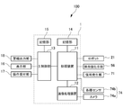
図1は、調理システム100の構成を示す図である。調理システム100は、制御装置1を含む。なお、制御装置1は、1つ以上のコンピュータにより実現されてもよい。この場合、1つ以上のコンピュータは、サーバコンピュータを含んでもよい。(First Example)
FIG. 1 is a diagram showing a configuration of a
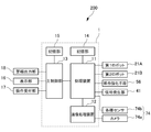
図1に示すように、本実施例の制御装置1は、作業装置としてのロボット21の動作を制御する処理装置11と、調理場50を撮像するカメラ74aの画像を処理する画像処理装置12と、主制御部13と、処理装置11における処理を規定するプログラム及び処理装置11における制御に必要なデータを格納する記憶部14と、主制御部13における処理を規定するプログラム及び主制御部13における制御に必要なデータを格納する記憶部15と、を備える。以下で説明する制御装置1の機能は、記憶部14及び/又は記憶部15内に記憶される1つ以上のプログラムを処理装置11及び/又は主制御部13が実行することで実現できる。なお、記憶部14及び記憶部15は共通の記憶装置により実現されてもよい。また、画像処理装置12は、例えばGPU(Graphics Processing Unit)単体であるが、処理装置11とは別の処理装置(GPUを含む処理装置)により実現されてもよい。
As shown in FIG. 1, the control device 1 of the present embodiment includes a processing device 11 that controls the operation of the
また、主制御部13には、制御装置1の動作状態等を表示する表示部16と、作業者等の操作を受け付ける操作受付部17と、警報出力部18とが接続されている。主制御部13は、表示部16や警報出力部18を介して、ユーザ(作業者)にアドバイスや警報を出力してよい。例えば、主制御部13は、複数のセンサ74、カメラ74a、各種センサ74bからのセンサ情報と、後述するロボット21に設けられる複数のセンサからのセンサ情報とに基づいて、所定の異常を検出した場合に、異常情報を発生させる処理を実行する。なお、検出対象の所定の異常は、任意であり、異常情報は、異常内容を指示や示唆するメッセージであってもよいし、単なる警報音等であってもよい。
Further, the
また、処理装置11は、係合強化手段56を制御する。係合強化手段56は、例えば電磁石であるが、吸引力(負圧)を発生させる負圧発生装置等であってもよいし、これらの組み合わせであってもよい。 Further, the processing device 11 controls the engagement strengthening means 56. The engagement strengthening means 56 is, for example, an electromagnet, but may be a negative pressure generating device or the like that generates an attractive force (negative pressure), or may be a combination thereof.
また、処理装置11は、信号発生部71からの情報に基づいて、係合強化手段56を制御する。信号発生部71は、例えば近接センサであってよいし、感圧センサや画像センサ等であってもよい。
Further, the processing device 11 controls the engagement strengthening means 56 based on the information from the
また、処理装置11は、調理場50に配置される複数のセンサ74に接続される。複数のセンサ74は、カメラ74a(画像センサ)や、他の各種センサ74bを含み、調理場50の状態を検出する機能を有する。なお、カメラ74aは、2台以上設けられてもよい。
Further, the processing device 11 is connected to a plurality of
主制御部13と処理装置11は、協働して調理に必要な処理を順次、実行する。
The
次に、図2以降を参照して、調理システム100が機能するのに好適な調理場50を詳説する。以下では、主に、蕎麦を調理することを例に説明するが、調理対象は、蕎麦以外の麺類(例えばうどん、ラーメン、パスタ)であってもよいし、麺類以外の任意の食材(何らかの調理が必要な食材)であってもよい。
Next, with reference to FIGS. 2 and later, a
図2は、複数のセクションを備える調理場50を示す図である。図2に示す例では、複数のセクションは、第1セクション51、第2セクション52、及び第3セクション53を含む。なお、セクションの数は、任意であり、第3セクション53は省略されてもよいし、更なるセクションが追加されてもよい。
FIG. 2 is a diagram showing a
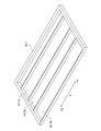
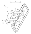
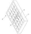
図3は、第1セクション51に配置されるレール511を示す斜視図である。第1セクション51では、レール511により複数のレーン511A、511B、511Cが規定される。1つ以上の“てぼ(ザル)”を保持するトレイ80(以下、単に「トレイ80」とも称する)は、レーンのいずれかに載置されて、Y方向Y1側へと搬送される。なお、この搬送は、作業者による手作業で実現されてもよいし、ロボット21以外のロボットや駆動機構で実現されてもよい。なお、レール511は、Y1側が下方になるように傾斜が付けられてもよい。この場合、トレイ80は、重力の作用により、Y方向Y1側へと移動できる。
FIG. 3 is a perspective view showing the
例えば、第1セクション51のレーンの最もY方向Y1側に、“てぼ(ザル)”を保持するトレイ80が位置すると、調理準備開始状態となる。
For example, when the
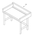
図4は、レール511の支持台512を示す斜視図である。支持台512は、レール511を取り外し可能に支持できる。これにより、レール511のメンテナンスが容易となる。
FIG. 4 is a perspective view showing a
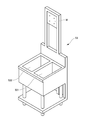
図5は、第3セクション53の設備を示す斜視図である。図5では、第3セクション53は、サブセクション531、532を有する。サブセクション531、532に割り当てられる作業は任意であるが、例えば水切り作業や、ぬめりを取る作業である。
FIG. 5 is a perspective view showing the equipment of the
本実施例では、図2に示すように、第3セクション53に、ロボット21が配置される。すなわち、第3セクション53を構成する設備の壁体W(図5参照)にロボット21の基端21aが取り付けられる。壁体Wを設備の一部として設けることにより、壁体W自体やその支持構造に充分な強度を確保することができる。ただし、取付強度等の問題がなければ調理場50の壁(建物の壁)や天井にロボット21の基端21aを取り付けることも可能である。なお、ロボットの21の基端21aは第1セクション51や第2セクション52を構成する壁体やロボットの21の基端21aの近くの壁(建物の壁)に取り付けられることとしてもよい。いずれの場合においてもロボットを各セクションの上方の空間に配置することができるので、調理システム全体の設置面積を低減することが可能となる。ただし、第1セクション51や第3セクションの壁に取り付ける方が、ロボット21の基端21aが第2セクション52に配置される場合に比べて、ロボット21のメンテナンスが容易となる。また、第2セクション52の上方に配置されうるダクトとの干渉の可能性が低減され、スペース効率の良い調理場50を実現できる。また、第1セクションに配置される場合と比較して、第3セクションに配置される方が、調理作業を実施する第2セクションまでの距離が短くなるので、小型のロボットでも対応可能となる。
In this embodiment, as shown in FIG. 2, the
図6は、第2セクション52の設備を示す斜視図である。第2セクション52には、蕎麦を茹でる作業が割り当てられる。
FIG. 6 is a perspective view showing the equipment of the
図7は、ロボット21の本体を示す斜視図である。なお、図7では、ロボット21は、ハンド本体部72が取り付けられていない状態で示される(図2も同様)。
FIG. 7 is a perspective view showing the main body of the
ロボット21は、複数の回転関節を有する多関節ロボットであり、基端21aが壁体Wに取り付けられる。なお、ロボット21として、回転関節だけでなく直動関節を有するロボット21を用いることもできる。ロボット21には、各関節を駆動するためのアクチュエータ(不図示)が関節ごとに設けられ、これらのアクチュエータが処理装置11に接続されて制御される。ロボット21の先端21bには、ロボット用ハンド70(図8)が取り付けられる。
The
本実施例ではロボット21は、多関節ロボットであり、壁体W側に退避させることができるので、サブセクション531、532の上方の作業スペースを効果的に確保できる。この場合、例えば図2に示す領域R1付近に立ちながら作業者が作業することも可能となり、ロボット21の非稼働時にも設備を有効に利用できる。
In this embodiment, the
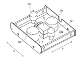
図8は、ロボット用ハンド70のハンド本体部72を示す斜視図である。図9は、プレート部材700を取り外した状態のハンド本体部72を示す斜視図である。図10は、ハンド本体部72とトレイ80との係合状態を示す斜視図である。図11は、トレイ80の単品状態を示す斜視図である。図12は、てぼ(ザル)を保持した状態のトレイ80を示す斜視図である。図8には、互いに直交する2つの方向としてX方向とY方向とが、ハンド本体部72の上面720を基準として定義されている。また、図10〜図12には、Z方向が定義されている。Z方向は、トレイ80のトレイ部81における支持面に垂直な方向であり、以下では、Z方向Z1側を、「上側」とし、Z方向Z2側を、「下側」として、上下方向に関連する用語(例えば上面や、下面等)を用いる場合がある。
FIG. 8 is a perspective view showing a
ロボット用ハンド70は、トレイ80をピックアップし、所定場所(第1セクション51等)に載置するのが好適に形成される。ロボット用ハンド70は、トレイ80に係合するハンド本体部72を有する。
The
ハンド本体部72は、係合する際にトレイ80の被支持部82の下面と面接触する上面720を有する。図8では、ハンド本体部72は、コの字断面状(X方向視の形状)のプレート部材700を含み、プレート部材700が上面720を形成する。上面720は、トレイ80の重力を受け持つ。すなわち、ハンド本体部72は、トレイ80の被支持部82をすくい上げる態様でピックアップする。これにより、ハンド本体部72を介してトレイ80を持ち上げている最中に、電源の異常等により、係合強化手段56が機能しなくなった場合でも、ハンド本体部72とトレイ80との間の係合を維持できる(すなわちトレイ80の落下を防止できる)。
The
ハンド本体部72には、ピン721が設けられる。ピン721は、例えば上面720から上側に突出する態様で設けられる。ピン721の数は任意であるが、図8では、2つであり、上面720におけるY方向の中心位置付近でX方向に離間して設けられる。ピン721は、トレイ80における対応する孔821に挿入されることで、ハンド本体部72がトレイ80に係合する際の位置決め機能を果たす。なお、変形例では、トレイ80側にピン(例えば下向きのピン)が形成され、ハンド本体部72側に対応する孔が形成されてもよい。
A
ピン721は、任意の断面形状であってもよいが、好ましくは、断面が円形であり、先端が細くなるテーパ状の形態である。これにより、係合直前にトレイ80とハンド本体部72との間に僅かなズレがある場合でも、当該ズレを矯正しつつ互いの係合状態を実現できる。
The
ハンド本体部72には、係合強化手段56(図8には概略的に図示)が設けられる。係合強化手段56は、好ましくは、X方向でピン721の間に設けられる。なお、上面720には、係合強化手段56用の穴561が形成されてよい。これにより、ハンド本体部72とトレイ80との間の係合度合いを効果的に高めることができる。係合強化手段56の数は任意であるが、図8では、2つであり、上面720におけるX方向の中心位置付近でY方向に離間して設けられる。本実施例では、係合強化手段56は、電磁石であり、被支持部82は、磁性体により形成される。これにより、電磁石がオン状態となると、ハンド本体部72とトレイ80との間の係合度合いが高くなる。これにより、外乱等により大きな振動等が生じた場合でも、ハンド本体部72とトレイ80との間の係合を維持できる可能性を高めることができる。
The
ハンド本体部72には、信号発生部71(図8には概略的に図示)が設けられる。信号発生部71は、上面720におけるトレイ80の被支持部82の下面と面接触する領域内に設けられる。なお、上面720には、信号発生部71用の穴711が形成されてよい。信号発生部71は、ハンド本体部72に対する被支持部82の近接状態を検出する。本実施例では、信号発生部71は、ハンド本体部72の上面720とトレイ80の被支持部82の下面との間のZ方向の距離が閾値以下となった場合に、近接状態を表す所定信号を発生する。信号発生部71は、例えば近接センサであってよい。
The hand
なお、ハンド本体部72は、図9に示すように、好ましくは、上面720よりも下方に搭載スペース750を有する。なお、図9は、上面720を形成するコの字断面状(X方向視の形状)のプレート部材700を取り外した状態で、ロボット用ハンド70が示される。搭載スペース750内には、ピン721の下部や、係合強化手段56、信号発生部71、配線等が配置されてよい。なお、図9では、信号発生部71を適切な位置に配置するためのスペーサ714が図示されている。
As shown in FIG. 9, the
本実施例では、ハンド本体部72にトレイ80が係合された状態が第1係合状態(図10参照)である。このとき、係合強化手段56は機能していないか、あるいは微弱である。なお、「微弱」とは、係合強化手段56が電磁石の場合、第2係合状態を実現するときの通電電流(又は磁力)を100とした場合、100よりも有意に小さいことを意味し、例えば50以下であり、好ましくは、10以下である。そして、係合強化手段56が機能すると、ハンド本体部72とトレイ80との間の係合度合いが高くなる第2係合状態が実現されてもよい。第1係合状態から第2係合状態への遷移(切り替え)は、処理装置11により実現される。具体的には、上述したように、信号発生部71が例えば近接センサである場合、近接センサは、トレイ80の、ハンド本体部72に対する第1係合状態が検出された場合に、所定信号を発生する。処理装置11は、この所定信号の発生をトリガとして、第1係合状態から第2係合状態への遷移(切り替え)を実現する。なお、信号発生部71は、好ましくは、ピン721を介して位置決めされていない係合状態では、所定信号を発生しないように構成される。すなわち、信号発生部71は、好ましくは、ピン721を介して位置決めされた係合状態を検出した場合のみ、所定信号を発生する。
In this embodiment, the state in which the
なお、第1係合状態と第2係合状態は、ロボット用ハンド70とトレイ80との位置関係は、同じであり、ともに図10に示す状態である。
In the first engaged state and the second engaged state, the positional relationship between the
なお、第1係合状態から第2係合状態への遷移(切り替え)は、ハンド本体部72の上面720にトレイ80の重力が作用している状態で実現されてもよい。なお、この場合、信号発生部71は、かかる重力の作用状態を検出するセンサ等であってもよい。
The transition (switching) from the first engaging state to the second engaging state may be realized in a state where the gravity of the
トレイ80は、図11に示すように、トレイ部81と、被支持部82と、脚部83とを含む。
As shown in FIG. 11, the
トレイ部81は、“てぼ(ザル)”が挿入される貫通孔810を有する。貫通孔810の個数は任意であるが、図11では、3つ設けられる。貫通孔810に挿入される“てぼ(ザル)”は、貫通孔810まわりの縁部により支持される。
The
被支持部82は、上述したように、ハンド本体部72に係合される部分である。被支持部82は、ハンド本体部72の上面720に面接触する下面を形成する。被支持部82は、ハンド本体部72のピン721が挿入(嵌入)される孔821を有する。
As described above, the supported
脚部83は、被支持部82をトレイ部81よりも上方に位置するように支持する。脚部83は、対で設けられ、上端部が、被支持部82のX方向両側の縁部に接続される。また、脚部83は、下端部がトレイ部81の上面に固定される。このような脚部83を設けることで、被支持部82の下方に、ハンド本体部72の上面720を形成する部分が位置できるように、被支持部82をトレイ部81に対して上方に支持できる。
The
本実施例では、第1セクション51で準備されたトレイ80は、図12に模式的に示すように、調理前の蕎麦が入った“てぼ(ザル)”を保持する。ロボット21は、第1セクション51上のトレイ80をピックアップして、第2セクション52まで搬送し(空中を移動させ)、第2セクション52内に用意された湯内に、トレイ80ごと漬ける。これにより、茹で作業(第1の調理処理の一例)を実現できる。茹で作業が開始されると、ロボット21は、一旦、トレイ80との係合を解消してもよい。この場合、茹で作業が終了するまで、他の作業を実現することも可能である。ついで、茹で作業が開始されてから所定時間が経過すると、ロボット21は、第2セクション52内のトレイ80をピックアップして、第3セクション53にて後処理(第2の調理処理の一例)を行う。すなわち、ロボット21は、まず、サブセクション531内に溜まった冷水に、トレイ80を浸して蕎麦のぬめりを除去する。なお、この際、ロボット21は、トレイ80を動かす等して作業効率を高めてもよい。また、調理場50は、サブセクション531内のトレイ80を検出すると、冷水が注入されるように構成されてもよい。ついで、ロボット21は、サブセクション532上にトレイ80を運び、水切り作業を行う。この際、ロボット21は、トレイ80を傾斜させて上下に振動させることで、水切りが効果的に実現されるようにしてもよい。ロボット21は、水切り作業を終了すると、第1セクション51にトレイ80を搬送し、第1セクション51上のレール511上にトレイ80を載置する。なお、この際、載置するレーンは、規定されてもよい。このようにして、一連の調理作業が実現される。
In this embodiment, the
このように、本実施例によれば、一連の調理作業中におけるトレイ80の動きは、調理場50におけるY方向Y2側の端部からY方向Y1側の端部まで搬送されてから、Y方向Y2側に戻る動きとなる。すなわち、往復動する双方向の動きである。
As described above, according to the present embodiment, the movement of the
ところで、トレイ80の動きが調理場50におけるY方向Y2側の端部からY方向Y1側の端部までの、一方向の動きだけで一連の調理作業を実現する比較例(図示せず)の場合、茹で作業に係るセクション(本例では、第2セクション52)を、茹でた後の作業を行うセクション(本例では第3セクション53)よりもY方向Y2側に配置する必要がある。この場合、ロボット21は、茹で作業に係るセクション(中央のセクション)に配置される必要性が高くなる。茹で作業に係るセクションにロボット21を配置すると、茹で作業の際の湯気等を受けてロボット21の耐久性が悪くなり得、また、ダクトとの干渉の可能性が増す。
By the way, in a comparative example (not shown) in which the movement of the
これに対して、本実施例によれば、往復動する双方向の動きで一連の調理作業を実現できるので、後処理を行うセクション(すなわち第3セクション53)に対応付けてロボット21を配置できる。これにより、ロボット21の耐久性が良好となり、かつ、ダクトの配索の自由度を高めることができる。
On the other hand, according to the present embodiment, since a series of cooking operations can be realized by reciprocating bidirectional movements, the
(第2の実施例)
以下、第2の実施例について説明する。図面において、実施例1と実質的に同一の要素には、同一符号を付している。(Second Example)
Hereinafter, the second embodiment will be described. In the drawings, the elements substantially the same as those in the first embodiment are designated by the same reference numerals.
図13は、調理システム200の構成を示す図である。調理システム200は、制御装置1を含む。なお、制御装置1は、1つ以上のコンピュータにより実現されてもよい。この場合、1つ以上のコンピュータは、サーバコンピュータを含んでもよい。
FIG. 13 is a diagram showing the configuration of the
図13に示すように、本実施例の制御装置1は、作業装置としてのロボット21A(第1ロボット)およびロボット21B(第2ロボット)の動作を制御する処理装置11と、調理場150を撮像するカメラ74aの画像を処理する画像処理装置12と、主制御部13と、処理装置11における処理を規定するプログラム及び処理装置11における制御に必要なデータを格納する記憶部14と、主制御部13における処理を規定するプログラム及び主制御部13における制御に必要なデータを格納する記憶部15と、を備える。以下で説明する制御装置1の機能は、記憶部14及び/又は記憶部15内に記憶される1つ以上のプログラムを処理装置11及び/又は主制御部13が実行することで実現できる。なお、記憶部14及び記憶部15は共通の記憶装置により実現されてもよい。また、画像処理装置12は、例えばGPU(Graphics Processing Unit)単体であるが、処理装置11とは別の処理装置(GPUを含む処理装置)により実現されてもよい。
As shown in FIG. 13, the control device 1 of the present embodiment captures an image of the processing device 11 that controls the operations of the
また、主制御部13には、制御装置1の動作状態等を表示する表示部16と、作業者等の操作を受け付ける操作受付部17と、警報出力部18とが接続されている。主制御部13は、表示部16や警報出力部18を介して、ユーザ(作業者)にアドバイスや警報を出力してよい。
Further, the
また、処理装置11は、係合強化手段56を制御する。係合強化手段56は、例えば電磁石であるが、吸引力(負圧)を発生させる負圧発生装置等であってもよいし、これらの組み合わせであってもよい。 Further, the processing device 11 controls the engagement strengthening means 56. The engagement strengthening means 56 is, for example, an electromagnet, but may be a negative pressure generating device or the like that generates an attractive force (negative pressure), or may be a combination thereof.
また、処理装置11は、信号発生部41からの情報に基づいて、係合強化手段56を制御する。信号発生部41は、例えば近接センサであってよいし、感圧センサや画像センサ等であってもよい。
Further, the processing device 11 controls the engagement strengthening means 56 based on the information from the
また、処理装置11は、調理場150に配置される複数のセンサ74に接続される。複数のセンサ74は、カメラ74a(画像センサ)や、他の各種センサ74bを含み、調理場150の状態を検出する機能を有する。なお、カメラ74aは、2台以上設けられてもよい。
Further, the processing device 11 is connected to a plurality of
主制御部13と処理装置11は、協働して調理に必要な処理を順次、実行する。
The
次に、図14以降を参照して、調理システム200が機能するのに好適な調理場150を詳説する。以下では、主に、蕎麦を調理することを例に説明するが、調理対象は、蕎麦以外の麺類(例えばうどん、ラーメン、パスタ)であってもよいし、麺類以外の任意の食材(何らかの調理が必要な食材)であってもよい。
Next, with reference to FIGS. 14 and later, a
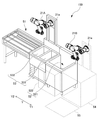
図14は、複数のセクションを備える調理場150を示す図、図15は、調理場150を示す上面図である。
FIG. 14 is a diagram showing a
図14に示す例では、複数のセクションは、第1セクション51、第2セクション52、第3セクション53および第4セクション54を含む。なお、セクションの数は、任意であり、更なるセクションが追加されてもよい。
In the example shown in FIG. 14, the plurality of sections includes a
図14に示すように、第2セクション52は、サブセクション521と、サブセクション522とを有する。サブセクション521には、蕎麦を茹でるための工程が割り当てられる。サブセクション522は、トレイ60を一時的に載置するための置台として機能する。なお、サブセクション522の構成は任意であるが、例えば、第1セクション51に配置されるレール511またはこれに類似した構造物を配置し、トレイ60を載置するための第1セクション51と同様のレーンを構成してもよい。
As shown in FIG. 14, the
図14に示すように、第3セクション53は、サブセクション531、532を有する。サブセクション531、532に割り当てられる作業は任意であるが、例えば水切り作業や、ぬめりを取る作業である。サブセクション521において茹でられた蕎麦を、サブセクション531、サブセクション532の順で、後処理することができる。例えば、サブセクション531において、蕎麦のぬめりを取る作業を中心に行い、さらに、サブセクション532において水で蕎麦をしめる(冷却する)作業を行うことができる。この場合、サブセクション532における水の温度を極力低下させることが要求される一方、サブセクション531における水の温度は極端に低くなくてもよい。このため、低温の冷水をサブセクション532のみに供給してもよい。この場合、サブセクション531における水位を、サブセクション532における水位よりも低く設定し、サブセクション532の水位を超えてサブセクション532から溢れた水が、自然にサブセクション531に供給されるようにしてもよい。これにより、サブセクション532に供給された冷水を、サブセクション531においても有効に利用できる。また、サブセクション531に対して、直接、水を供給する必要がなくなる。
As shown in FIG. 14, the
本実施例では、図14に示すように、第3セクション53に、ロボット21Aが配置される。すなわち、第3セクション53を構成する設備の壁体W(図5参照)にロボット21Aの基端21aが取り付けられる。
In this embodiment, as shown in FIG. 14, the
また、図15に示すように、本実施例では、第4セクション54にロボット21Bが配置される。すなわち、第4セクション54を構成する設備の壁体W1(図15参照)にロボット21Bの基端21aが取り付けられる。なお、ロボットの21Bの基端21aは少なくともロボット21Aの基端21aよりも第4セクションに近いセクションに設けられればよくいずれの場合においても、ロボット21との干渉を抑制しつつロボットを各セクションの上方の空間に配置することができ、調理システム全体の設置面積を低減することが可能となる。ただし、図14に示すように第4セクション54の壁に取り付ける方が、ロボット21Bによる後述の動作を容易に実行することが可能となる。ロボット21Bが、第2セクション52ではなく、第4セクション54に設けられることで、第2セクション52への排気ダクト等の搭載が容易となり、また、第2セクション52で発生する蒸気(茹でる際の蒸気)がロボット21Bに直接的に当たることを抑制できる。なお、ロボット21Bを第2セクション52など、他の場所に配置してもよい。壁体Wおよび壁体W1を設備の一部として設けることにより、壁体Wおよび壁体W1自体やその支持構造に充分な強度を確保することができる。ただし、取付強度等の問題がなければ調理場50の壁(建物の壁)や天井に、ロボット21Aまたはロボット21Bの基端21aを取り付けることも可能である。
Further, as shown in FIG. 15, in this embodiment, the
図14に示す第4セクション54は、蕎麦を入れる容器(ばんじゅう)を載置する置台として機能する。
The
ロボット21Aおよびロボット21Bは、図7に示すロボット21と同一の構成を有する。
The
すなわち、ロボット21A、21Bは、複数の回転関節を有する多関節ロボットである。なお、ロボット21A、21Bとして、回転関節だけでなく直動関節を有するロボットを用いることもできる。ロボット21A、21Bには、各関節を駆動するためのアクチュエータ(不図示)が関節ごとに設けられ、これらのアクチュエータが処理装置11に接続されて制御される。本実施例では、ロボット21Aの先端21bには、ロボット用ハンド40が取り付けられる。また、ロボット21Bの先端21bには、ロボット用ハンド30が取り付けられる。
That is, the
本実施例ではロボット21A、21Bは、多関節ロボットであり、壁体W、W1側に退避させることができるので、例えば、サブセクション531、532の上方の作業スペースを効果的に確保できる。この場合、調理場150内で作業者が作業することも可能となり、ロボット21A、21Bの非稼働時にも設備を有効に利用できる。
In this embodiment, the
図16は、ロボット用ハンド40のハンド本体部42を示す斜視図である。図17は、上面420を構成する部材を取り外した状態のハンド本体部42を示す斜視図である。図18は、ハンド本体部42とトレイ60との係合状態を示す斜視図である。図19は、トレイ60の単品状態を示す斜視図、図19Aは、トレイ60に“てぼ(ザル)”が挿入された状態を示す斜視図である。図16には、互いに直交する2つの方向としてX方向とY方向とが、ハンド本体部42の上面420を基準として定義されている。また、図18、図19および図19Aには、Z方向が定義されている。Z方向は、トレイ60のトレイ部61における支持面に垂直な方向であり、以下では、Z方向Z1側を、「上側」とし、Z方向Z2側を、「下側」として、上下方向に関連する用語(例えば上面や、下面等)を用いる場合がある。
FIG. 16 is a perspective view showing a
ロボット用ハンド40は、トレイ60をピックアップし、所定位置(第1セクション51、サブセクション522等)に載置するのが好適な形状に形成される。ロボット用ハンド40は、トレイ60に係合するハンド本体部42を有する。
The
ハンド本体部42は、係合する際にトレイ60の一対の被支持部62の下面と面接触する上面420を有する。図16では、上面420は、ロボット21Aの先端21bに取り付けられる取付面400Aを有するプレート部材400により支持される。上面420は、トレイ60の重力を受け持つ。すなわち、ハンド本体部42は、トレイ60の被支持部62をすくい上げる態様でピックアップする。これにより、ハンド本体部42を介してトレイ60を持ち上げている最中に、電源の異常等により、係合強化手段56が機能しなくなった場合でも、ハンド本体部42とトレイ60との間の係合を維持できる(すなわちトレイ60の落下を防止できる)。
The
ハンド本体部42には、ピン421が設けられる。ピン421は、例えば上面420から上側に突出する態様で設けられる。ピン421の数は任意であるが、図16では、2つであり、一対の被支持部62のそれぞれに対応して設けられる。ピン421は、トレイ60における対応する孔621に挿入されることで、ハンド本体部42がトレイ60に係合する際の位置決め機能を果たす。なお、変形例では、トレイ60側にピン(例えば下向きのピン)が形成され、ハンド本体部42側に対応する孔が形成されてもよい。
The
ピン421は、任意の断面形状であってもよいが、好ましくは、断面が円形であり、先端が細くなるテーパ状の形態である。これにより、係合直前にトレイ60とハンド本体部42との間に僅かなズレがある場合でも、当該ズレを矯正しつつ互いの係合状態を実現できる。
The
ハンド本体部42には、係合強化手段56(図16には概略的に図示)が設けられる。なお、上面420には、係合強化手段56用の穴561が形成されてよい。これにより、ハンド本体部42とトレイ60との間の係合度合いを効果的に高めることができる。係合強化手段56の数は任意であるが、図16では、2つであり、一対の被支持部62のそれぞれに対応して設けられる。本実施例では、係合強化手段56は、電磁石であり、被支持部62は、磁性体により形成される。これにより、電磁石がオン状態となると、ハンド本体部42とトレイ60との間の係合度合いが高くなる。これにより、外乱等により大きな振動等が生じた場合でも、ハンド本体部42とトレイ60との間の係合を維持できる可能性を高めることができる。
The
ハンド本体部42には、信号発生部41(図17には概略的に図示)が設けられる。信号発生部41は、上面420におけるトレイ60の被支持部62の下面と面接触する領域内に設けられる。なお、上面420には、信号発生部41用の穴(不図示)が形成されてよい。信号発生部41は、ハンド本体部42に対する被支持部62の近接状態を検出する。本実施例では、信号発生部41は、ハンド本体部42の上面420とトレイ60の被支持部62の下面との間のZ方向の距離が閾値以下となった場合に、近接状態を表す所定信号を発生する。信号発生部41は、例えば近接センサであってよい。なお、信号発生部41は、被支持部62に対応して対で設けられてもよいし、一方の被支持部62にのみ対応して設けられてもよい。
The
なお、ハンド本体部42は、図17に示すように、好ましくは、上面420よりも下方に搭載スペース450を有する。なお、図17では、上面420を形成する部材を取り外した状態で、ロボット用ハンド40が示される。搭載スペース450内には、ピン421の下部や、係合強化手段56、信号発生部41、配線等が配置されてよい。
As shown in FIG. 17, the
本実施例では、ハンド本体部42にトレイ60が係合された状態が第1係合状態(図18参照)である。このとき、係合強化手段56は機能していないか、あるいは微弱である。なお、「微弱」とは、係合強化手段56が電磁石の場合、第2係合状態を実現するときの通電電流(又は磁力)を100とした場合、100よりも有意に小さいことを意味し、例えば50以下であり、好ましくは、10以下である。そして、係合強化手段56が機能すると、ハンド本体部42とトレイ60との間の係合度合いが高くなる第2係合状態が実現されてもよい。第1係合状態から第2係合状態への遷移(切り替え)は、処理装置11により実現される。具体的には、上述したように、信号発生部41が例えば近接センサである場合、近接センサは、トレイ60の、ハンド本体部42に対する第1係合状態が検出された場合に、所定信号を発生する。処理装置11は、この所定信号の発生をトリガとして、第1係合状態から第2係合状態への遷移(切り替え)を実現する。なお、信号発生部41は、好ましくは、ピン421を介して位置決めされていない係合状態では、所定信号を発生しないように構成される。すなわち、信号発生部41は、好ましくは、ピン421を介して位置決めされた係合状態を検出した場合のみ、所定信号を発生する。
In this embodiment, the state in which the
なお、第1係合状態と第2係合状態は、ロボット用ハンド40とトレイ60との位置関係は、同じであり、ともに図18に示す状態である。
In the first engaged state and the second engaged state, the positional relationship between the
なお、第1係合状態から第2係合状態への遷移(切り替え)は、ハンド本体部42の上面420にトレイ60の重力が作用している状態で実現されてもよい。なお、この場合、信号発生部41は、かかる重力の作用状態を検出するセンサ等であってもよい。
The transition (switching) from the first engaging state to the second engaging state may be realized in a state where the gravity of the
図19に示すように、トレイ60は、トレイ部61と、一対の被支持部62と、トレイ部61と被支持部62とを接続する脚部63とを含む。
As shown in FIG. 19, the
トレイ部61は、調理器具としての“てぼ(ザル)”が挿入される、支持部としての複数の貫通孔610を有する。貫通孔610の個数は任意であるが、図19では、3つ設けられる。貫通孔610に挿入される“てぼ(ザル)”は、貫通孔610まわりの縁部により支持される。図19Aにおいて、貫通孔610に挿入された“てぼ(ザル)”のざる65の部分を示している。実際には、3つの貫通孔610のそれぞれに対して、“てぼ(ザル)”を挿入することができる。
The
被支持部62は、上述したように、ハンド本体部42に係合される部分であり、第1の被係合部および第2の被係合部を構成する。被支持部62は、ハンド本体部42の上面420に面接触する下面を形成する。被支持部62は、ハンド本体部42のピン421が挿入(嵌入)される孔621を有する。
As described above, the supported
脚部63は、被支持部62をトレイ部61よりも上方に位置するように支持する。脚部63は、被支持部62に対応して対で設けられ、それぞれの上端部が、対応する被支持部62の縁部に接続される。また、脚部63は、下端部がトレイ部61の上面に固定される。このような脚部63を設けることで、被支持部62の下方に、ハンド本体部42の上面420を形成する部分が位置できるように、被支持部62をトレイ部61に対して上方に支持できる。
The
また、本実施例では、脚部63を、上方から視て、隣り合う貫通孔610の中間の位置に設けている。さらに、一対の被支持部62のそれぞれを一対の脚部63のそれぞれに対応させるとともに、上方から視たときの被支持部62の面積を抑制している。このため、貫通孔610に挿入された“てぼ(ザル)”の上方を広く開放することができ、“てぼ(ザル)”への蕎麦の投入が容易に行える。すなわち、脚部63および被支持部62が貫通孔610に挿入された“てぼ(ザル)”の上方から回避した位置にあるため、蕎麦を投入する際の障害となることがなく、貫通孔610に挿入された“てぼ(ザル)”に蕎麦を投入することができる。例えば、3つ並んだ貫通孔610のうち、中央に位置する貫通孔610は、上方から視たときに、被支持部62および脚部63に重ならない位置に設けられている。このため、この貫通孔610に挿入された“てぼ(ザル)”に対しても、一対の被支持部62および一対の脚部63の間から、容易に蕎麦を投入することができる。
Further, in this embodiment, the
図20は、ロボット用ハンド30を示す斜視図である。
FIG. 20 is a perspective view showing the
ロボット用ハンド30は、茹でる前の蕎麦を把持するとともに、把持された蕎麦を所定の位置で解放するのに適した形態に構成される。
The
図20に示すように、ロボット用ハンド30は、ロボット21Bの先端21bに固定される基部31と、基部31に対して矢印35の方向に、それぞれスライド可能に移動する可動部32および可動部33と、を備える。可動部32には4本の爪32a〜32dが、可動部33には4本の爪33a〜33dが、それぞれ設けられている。可動部32および可動部33は、同時に、矢印35に沿った方向であって、互いに反対方向に移動する。ロボット用ハンド30は、可動部32および可動部33の間の距離が最短になる閉状態と、当該距離が最長になる開状態との間で、繰り返し状態を切り替えることが可能とされている。爪32a〜32dおよび爪33a〜33dは、それぞれ、図20に示すA方向(矢印35と直交する方向)に沿って配列されている。
As shown in FIG. 20, the
爪32a〜32dは、それぞれ、可動部32から直線状に延びる基端部321(図20では、爪32aのみに表示)と、基端部321から折り曲げて形成された先端部332(図20では、爪32aのみに表示)とを有する。同様に、爪33a〜33dは、それぞれ、可動部33から直線状に延びる基端部331(図20では、爪33aのみに表示)と、基端部331から折り曲げて形成された先端部332(図20では、爪33aのみに表示)とを有する。図20の例では、基端部321および基端部331は、互いに平行に延びている。
The
爪32aと爪33a、爪32bと爪33b、爪32cと爪33c、および、爪32dと爪33dは、それぞれ対をなしており、対をなす爪の先端部322と先端部332が互いに爪の先に向かって接近する方向に延びている。
The
ロボット用ハンド30が閉状態にあるとき、爪32a〜32dの先端が、それぞれ爪33a〜33dの先端に接近し、茹でる前の蕎麦を、爪32a〜32dと爪33a〜33dの間に挟み込むようにして保持可能とされる。このとき、対を成す爪の先端部322と先端部332が互いに接近する方向に延びているので、基端部321および基端部331が蕎麦を挟み込むように蕎麦の両側の側部を覆うと同時に、先端部322と先端部332が蕎麦を下方から支持する。このため、蕎麦が落下することを効果的に防止できる。なお、ロボット用ハンド30が閉状態にあるとき、対をなす爪の先端部322と先端部332が互いに接触してもよく、あるいは、わずかの間隔をあけて互いに離れていてもよい。先端部322と先端部332の位置関係は、把持する対象物の特性に応じて、適宜、設定することができる。
When the
ロボット用ハンド30が閉状態から開状態に遷移すると、爪32a〜32dと爪33a〜33dの間に挟み込まれて保持されていた蕎麦が、先端部322と先端部332の間を滑り落ちるように自重により落下することで、ロボット用ハンド30からリリースされる。
When the
図20に示すように、爪を対で設ける場合には、爪の総数は偶数(図20では、8つ)となる。またこのとき、爪によって掴まれた蕎麦の落下を防止する観点から、爪の対の数を2以上とすることが望ましい。すなわち、爪の数を4つ以上とすることが望ましい。 As shown in FIG. 20, when the claws are provided in pairs, the total number of claws is an even number (8 in FIG. 20). At this time, it is desirable that the number of pairs of claws is 2 or more from the viewpoint of preventing the buckwheat noodles gripped by the claws from falling. That is, it is desirable that the number of claws is 4 or more.
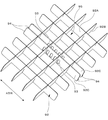
図21は、蕎麦を入れる容器90を示す斜視図、図22は、仕切り92を示す斜視図である。
21 is a perspective view showing a
容器90は、有底形状の容器本体91と、容器本体91の内部を区画する仕切り92とからなる。容器本体91の矩形状の内部は、仕切り92の立壁92A、92B、92Cによってマトリクス状に区画されている。例えば、図22における領域95は、仕切り92によって区画された領域の一つを示している。仕切り92によって区画された領域ごとに、一纏りの蕎麦が入れられる。
The
なお、仕切り92の形状は任意であり、例えば、複数のサイズの領域が形成されるように、仕切り92の間隔に変化を与えてもよい。これにより異なる蕎麦の分量、例えば、大盛り、少量盛りなどにも対応することが可能となる。
The shape of the
仕切り92によって区画された領域のそれぞれには、茹でる前の蕎麦が既定量、例えば、一人分の量が入れられる。仕切り92によって区画された領域に、茹でる前の蕎麦をあらかじめセットしておくことにより、ロボット用ハンド30によって、当該領域に入れられている蕎麦の全量を確実に掴むことが可能となる。すなわち、開状態にあるロボット用ハンド30の爪32a〜32dおよび爪33a〜33dを当該領域内に差し込み、ロボット用ハンド30を閉状態に遷移させると、当該領域に入れられている蕎麦が爪32a〜32dと爪33a〜33dの間に挟み込まれて、当該領域に入れられていた蕎麦の全量が保持される。ロボット用ハンド30によって、ばらける可能性のある蕎麦などの調理対象を一纏めごとに掴むことができる。
Each of the areas partitioned by the
ロボット用ハンド30を所定の位置に移動させ、ロボット用ハンド30を開状態に遷移させると、その位置において蕎麦がリリースされる。
When the
図21、図22に示すように、仕切り92には、ロボット用ハンド30の爪32a〜32dおよび爪33a〜33dが係合可能な係合部としての係合孔93が形成されている。図22に示すA方向における係合孔93のピッチは、図20に示すA方向の爪32a〜32dおよび爪33a〜33dのピッチに一致している。また、仕切り92には、容器本体91に対して、仕切り92を係合させるための係合爪94が形成されている。
As shown in FIGS. 21 and 22, the
図20および図22におけるA方向を合致させた状態において、開状態にあるロボット用ハンド30の爪32a〜32dおよび爪33a〜33dを容器本体91内の所定位置に下向きに差し込み、ロボット用ハンド30を閉状態に遷移させると、係合孔93に爪32a〜32dおよび爪33a〜33dが挿入される。その状態からロボット用ハンド30を上昇させると、爪32a〜32dおよび爪33a〜33dが係合孔93に係合した状態で、仕切り92とともに、係合爪94を介して仕切り92に係合した容器本体91が、すなわち容器90の全体が持ち上がる。その後、ロボット用ハンド30を移動させて、容器90を所定位置に載置し、ロボット用ハンド30を開状態に遷移させると、爪32a〜32dおよび爪33a〜33dが係合孔93から外れる。このようにして、容器90を所定位置に移動することができる。
In the state where the directions A in FIGS. 20 and 22 are matched, the
このように、仕切り92に、ロボット用ハンド30の爪32a〜32dおよび爪33a〜33dが係合可能な係合孔93が形成されているので、ロボット21Bは、ロボット用ハンド30を介して、茹でる前の蕎麦を掴んで搬送するだけでなく、容器90を掴んで搬送する機能を発揮する。このため、容器90を移動するためにロボットの台数を増やし、あるいはロボット用ハンドを複数種類、用意し、ハンドを付け替える必要がない。例えば、ロボット21Bは、ロボット用ハンド30を介して、空になった容器90を第4セクション54から、第5セクション55(図14)に移動することができる。第4セクション54に、あらかじめ、蕎麦の入った容器90を積み上げるようにしておけば、空になった容器90を上から順に、ロボット21Bによって、適時、例えば、第5セクション55の床に置かれたテーブルや台車などの上に移動することが可能となる。容器90を第5セクション55に対してリリースする際に、ロボット用ハンド30に印加される容器90の重量をセンサにより計測し、当該重量が所定値よりも小さくなったタイミングで容器90をリリースしてもよい。これにより、容器90が実質的に第5セクション55に載置された状態で、容器90をリリースすることが可能となり、容器90の落下を防止できる。
As described above, since the
また、容器90に、センサ74bに含まれる重量センサを設け、重量センサにより容器90に蕎麦が入っているか否かを検出してもよい。容器90内の蕎麦がすべて搬送され、容器90が空になった場合に、この重量センサからの検出情報に基づいて、処理装置11がロボット21Bに対して、容器90を第5セクション55に移動する指令を送出することができる。容器90が空になったことをカメラ74a(画像センサ)による画像に基づいて、画像処理装置12における処理により検出してもよい。また、他のセンサ74b、例えば、第4セクション54に設けられた重量センサにより、これを検出してもよい。容器90に蕎麦が残っていることが検出される間は、蕎麦を搬送する作業が実行される。
Further, the
図22では、係合孔93が全部で10個設けられているが、個数は任意である。爪32a〜32dおよび爪33a〜33dの数に合わせて8個としてもよい。また、係合孔93として例示した係合部の形状も限定されない。係合部は孔でなくてもよく、爪32a〜32dおよび爪33a〜33dが係合可能とされていればよい。
In FIG. 22, a total of 10 engaging
なお、蕎麦を掴む場合と、容器90を持ち上げる場合において、ロボット用ハンド30の開状態または閉状態における先端部322と先端部332の間の距離を、それぞれの場合に最適化させ、互いに異なるものとしてもよい。
The distance between the
また、ロボット用ハンド30の閉状態において、爪32a〜32dおよび爪33a〜33dを駆動するモータのトルクをそれぞれの場合に適合させ、互いに異なるものとしてもよい。これにより、蕎麦を掴む場合の力および容器90を掴む場合の力を最適化できる。
Further, in the closed state of the
次に、本実施例における動作について説明する。 Next, the operation in this embodiment will be described.
本実施例では、第1セクション51で準備されたトレイ60は、空の “てぼ(ザル)”を保持する(図19A)。ロボット21Aは、ロボット用ハンド40を介して第1セクション51上のトレイ60をピックアップして、第2セクション52まで搬送し(空中を移動させ)、第2セクション52内のサブセクション522にトレイ60を載置する。なお、本実施例では、トレイ60を載置する所定位置として、サブセクション522を例示しているが、トレイ60を載置する位置は任意である。サブセクション522にトレイ60を載置する場合には、次にトレイ60が搬送されるサブセクション521がサブセクション522に隣接しているため、搬送時間が短縮できるという利点がある。
In this embodiment, the
一方、ロボット21Bは、ロボット用ハンド30によって第4セクション54上の容器90に入れられている茹でる前の蕎麦を掴む。上記のように、ここでは、ロボット用ハンド30を開状態から閉状態に遷移させることにより、仕切り92により区画された領域の1つから、茹でる前の蕎麦を、爪32a〜32dおよび爪33a〜33dによって掴むことができる。
On the other hand, the
次に、ロボット21Bは、ロボット用ハンド30によって、茹でる前の蕎麦を第2セクション52まで搬送し(空中を移動させ)、第2セクション52内のサブセクション521まで移動し、トレイ60に挿入された、対応する“てぼ(ザル)”に茹でる前の蕎麦を投入する。上記のように、蕎麦の投入時には、対応する“てぼ(ザル)”の内部または上方まで蕎麦を移動させる。次に、ロボット用ハンド30を閉状態から開状態に遷移させることにより、掴んでいた蕎麦を落下させ、対応する“てぼ(ザル)”に蕎麦を投入することができる。
Next, the
このとき、上記のように、トレイ60の脚部63を、上方から視て、隣り合う貫通孔610の中間の位置に設け、さらに、一対の被支持部62のそれぞれを一対の脚部63のそれぞれに対応して設けている(図18)。このため、貫通孔610に挿入された“てぼ(ザル)”の上方が開放され、脚部63や被支持部62がロボット用ハンド30や、搬送される蕎麦と干渉しない。このため、容易に貫通孔610に挿入された“てぼ(ザル)”に蕎麦を投入することができる。3つ並んだ貫通孔610のうち、中央に位置する貫通孔610に挿入された“てぼ(ザル)”に対しては、一対の脚部63の間から蕎麦を投入することができる。
At this time, as described above, the
このような、ロボット用ハンド30によって第4セクション54上の容器90に入れられている蕎麦を搬送し、対応する“てぼ(ザル)”に投入するという一連の動作を3回繰り返すことにより、トレイ60に挿入されている3つの“てぼ(ザル)”のすべてに蕎麦を投入することができる。なお、蕎麦を投入するまでの一連の動作は、カメラ74aの撮影画像などに基づいて適切に変更され得る。例えば、トレイ60に1つまたは2つの“てぼ(ザル)”が挿入されている場合には、“てぼ(ザル)”の個数に応じた回数だけ、一連の動作を繰り返すことができる。また、容器90に入れられている蕎麦の状況、例えば、蕎麦が入っている領域の個数に応じて、動作が変更され得る。
By repeating such a series of operations of transporting the buckwheat noodles contained in the
ロボット21Bがロボット用ハンド30を第2セクション52から退去させた後、ロボット21Aは、ロボット用ハンド40を介してサブセクション522上のトレイ60をピックアップして、第2セクション52のサブセクション521に用意された湯内に、トレイ60ごと漬ける。これにより、茹で作業を実行できる。茹で作業が開始されると、ロボット21Aは、一旦、トレイ60との係合を解消してもよい。この場合、茹で作業が終了するまで、他の作業を実行することも可能である。
After the
ついで、茹で作業が開始されてから所定時間が経過すると、ロボット21Aは、第2セクション52内のトレイ60をピックアップして、第3セクション53にて後処理を行う。すなわち、ロボット21Aは、まず、サブセクション531内に溜まった冷水に、トレイ60を浸して蕎麦のぬめりを除去する。なお、この際、ロボット21Aは、トレイ60を動かす等して作業効率を高めてもよい。また、調理場150は、サブセクション531内のトレイ60を検出すると、冷水が注入されるように構成されてもよい。
Then, when a predetermined time has elapsed from the start of the boiling work, the
ついで、ロボット21Aは、サブセクション532上にトレイ60を運び、水切り作業を行う。この際、トレイ60を傾斜させて上下に振動させることで、水切りが効果的に実現されるようにしてもよい。ロボット21Aは、水切り作業を終了すると、第1セクション51にトレイ60を搬送し、第1セクション51上のレール511上にトレイ60を載置する。なお、この際、載置するレーンは、規定されてもよい。このようにして、一連の調理作業が実現される。
Then, the
次に、蕎麦を容器90からてぼに投入する動作を繰り返す過程で、容器90内の蕎麦がなくなった際の処理について説明する。ロボット21Aは、容器90に予め設けられた重量センサなどの各種センサ74bやカメラ74aの画像から容器90内の蕎麦がなくなったことを検知する。重量センサを用いる場合は容器90と仕切り92を合算した重量以上の重さを検知しなくなれば蕎麦がなくなったことを検知でき、カメラ74aを用いる場合には仕切り内のすべての区画に蕎麦があるかないかを判定することで検知できる。そして、蕎麦がなくなったことを検知した場合には、ロボット用ハンド30によって容器90を把持・搬送する。新たな蕎麦が入った容器90については予め容器90を複数重ねておき、空の容器90を搬送すれば自動的に新たな蕎麦を把持できる状態になるようにしてもよいし、他のセクション(不図示)から新たな蕎麦が入った容器90を搬送することなどとしてもよい。
Next, in the process of repeating the operation of putting the buckwheat noodles from the
ロボット用ハンド30による容器90の搬送にあたっては、ロボット21Aが容器90の上方までロボット用ハンド30を移動させ、ロボット用ハンド30によって容器90の仕切り92を把持し、搬送させる。また、より詳細には、仕切り92を把持する際に、仕切り92に設けられた係合孔93にロボット用ハンド30の先端部332を挿入し、係合孔93を介して爪32a〜32dおよび爪33a〜33dと仕切り92を係合させ容器90を掴む。上記のように、ロボット用ハンド30によって蕎麦だけでなく容器90も搬送することで容器90の入れ替え作業についても追加のシステムを導入することなくロボットによる自動化を実現できる
ところで、蕎麦を茹でるために必要な一連の工程を成立させるために、当然ながら、処理装置11(図13)は、各動作が終了した後に、次の動作に移行させる制御を実行している。例えば、ロボット21Aが第2セクション52内のサブセクション522にトレイ60を載置した後に、ロボット21Bが茹でる前の蕎麦をサブセクション522に置かれたトレイ60に挿入された “てぼ(ザル)”に投入する。すべての“てぼ(ザル)”に蕎麦が投入された後に、ロボット21Aがトレイ60をピックアップして、第2セクション52のサブセクション521に漬けることにより、蕎麦の茹作業が開始される。以降、複数の作業が順次、実行されて、最後にしめられた(冷却された)状態の蕎麦が、第1セクション51上に置かれることにより、すべての工程が終了する。When transporting the
このような工程を一回だけ最短時間で実行するためには、ロボット21Aとロボット21Bの動きが互いに干渉しない範囲において、特定の作業が終了し、次の作業に移行するまでの時間を極力短くすればよい。この場合、例えば、ロボット21Aまたはロボット21Bは、特定の作業が終了した時点で、次の作業を開始すべき旨の指令を受信し、これに従って、ロボット21Aまたはロボット21Bによる次の作業が開始されればよい。
In order to execute such a process only once in the shortest time, the time from the completion of a specific work to the next work is as short as possible within the range where the movements of the
しかし、上記の一連の工程が同時に重なり合うように連続して行われる場合には、各工程に要する作業時間を考慮する必要がある。例えば、第2セクション52のサブセクション521で実行される蕎麦の茹で作業は、時間が決められており、所定の時間を越えて茹でることは許されないが、所定の茹で時間が経過したタイミングでロボット21Aが別の作業をしていると茹で作業中の蕎麦を所定の時間以上茹でてしまう恐れがあった。
However, when the above series of steps are continuously performed so as to overlap each other at the same time, it is necessary to consider the working time required for each step. For example, the buckwheat boiling work performed in the
このため、本実施例では、処理装置11により、一連の工程を繰り返す場合における作業の開始タイミングを管理している。 Therefore, in this embodiment, the processing device 11 manages the start timing of the work when the series of steps is repeated.
図23は、一連の工程における作業のタイミングを示すタイムチャートである。また、図24は、調理場の使用方法を例示する図である。 FIG. 23 is a time chart showing the timing of work in a series of steps. Further, FIG. 24 is a diagram illustrating how to use the kitchen.
図23において、時間経過の方向が右方向であり、図23のレーンLN1〜LN3は、それぞれ、図24に示す第1セクション51に設定されたレーンLN1〜LN3に置かれたトレイ60に対応している。図23は、レーンLN1〜LN3に置かれたトレイ60に対する作業を示している。例えば、最上段に示されたタイムチャートは、レーンLN1に置かれたトレイ60に対する作業を、2段目に示されたタイムチャートは、レーンLN2に置かれたトレイ60に対する作業を、それぞれ示している。
In FIG. 23, the direction of passage of time is to the right, and the lanes LN1 to LN3 in FIG. 23 correspond to the
図24は、上方から視た調理場150の一部を示している。図24では、サブセクション521において、2つのトレイ60に対し同時に調理(蕎麦を茹でる調理)をすることができることを示している。ただし、調理場のスペースや必要な調理スピード等によっては、3つ以上のトレイ60を同時に調理できるようにしてもよい。
FIG. 24 shows a part of the
図23における工程ST1は、調理指令を受信したロボット21Aにより、第1セクション51のトレイ60を搬送して第2セクション52内のサブセクション522に載置する作業に対応する。調理指令は、券売機において顧客が券売機で商品購入した情報を受信することで生成してもよいし、店員が顧客から注文を受けた後に調理システムを操作することで生成されることとしてもよい。工程ST11は、トレイ60がサブセクション522載置していることを検知して、ロボット21Bにより、サブセクション522に載置されたトレイ60の“てぼ(ザル)”に、茹でる前の蕎麦をセットする作業に対応する。ロボット21Bはその時点での注文数に応じて、トレイ60の3つのてぼに蕎麦をセットする。すなわち、注文数が3以上であれば、全てのてぼに蕎麦をセットし、注文数が2以下であれば注文数分だけてぼに蕎麦をセットする。工程ST2は、てぼに蕎麦をセットする作業が終了したことを検知して、ロボット21Aにより、サブセクション522のトレイ60をサブセクション521まで移動し、サブセクション521に投入する作業に対応する。
Step ST1 in FIG. 23 corresponds to the work of transporting the
工程ST3は、ロボット21Aにより、サブセクション521において、蕎麦を茹でる作業に対応する。工程ST3に含まれる工程ST31は、ロボット21Aにより、トレイ60を揺すり、蕎麦を湯の中でほぐす作業に対応する。工程ST31では、湯を溜めたサブセクション522のシンクの中央寄りの領域でトレイ60を揺する作業が行われる。蕎麦の茹で時間は、工程ST3の時間に対応するので、工程ST3の時間は厳密に管理される。なお、工程ST3の時間が守られることを前提として、工程ST31が終了した時点で、トレイ60をサブセクション521にセットし、一旦、ロボット21Aがトレイ60をリリースしてサブセクション521から退去することは可能である。
Step ST3 corresponds to the work of boiling buckwheat noodles in
工程ST4は、所定の茹で時間経過するタイミングで、ロボット21Aにより、トレイ60を第2セクション52から第3セクション53に搬送し、サブセクション531およびサブセクション532において、順次、蕎麦のぬめりを取り、さらに蕎麦をしめる作業に対応する。工程ST4の作業は、工程ST3における茹で時間を管理するために、その開始タイミングが厳密に管理される。工程ST5は、工程ST4を経たトレイ60を第1セクション51の対応するレーンLN1〜LN3に戻す作業に対応する。
In step ST4, the
なお、工程ST5の作業が終了後、同じレーンの工程ST1の作業が開始される前に、作業者は、第1セクション51から茹で上がった蕎麦が入ったトレイ60を受け取り、新たなトレイ60を第1セクション51の対応するレーンセットする作業を行う。
After the work of the process ST5 is completed and before the work of the process ST1 in the same lane is started, the worker receives the
ところで、上記のように、サブセクション521は、同時に2つ以上のトレイ60を受け入れ、これらのトレイ60に入った蕎麦を同時に茹でることができる。したがって、図23に例示した工程を組む場合、レーンLN1(図23の最上段)の工程ST31を終了した時点で、ロボット21Aは、レーンLN2(図23の2段目)の工程ST2に移行することも可能である。しかし、本実施例では、蕎麦を茹でる時間を守るために、処理装置11は、工程ST31の作業終了後、所定時間が経過してからロボット21Aによる、次のレーンの工程ST2の作業を開始している。これは、実質的に、工程ST2の作業のタイミングに応じて、次のレーンのトレイ60に対する工程ST2の作業のタイミングを規定していることを意味する。仮に、レーンLN1の工程ST31の作業終了後、上記の所定時間が経過する前にロボット21AによるレーンLN2の工程ST2の作業を開始した場合には、レーンLN1の工程ST4または工程ST5の作業中に、レーンLN2の工程ST4の開始時刻になってしまい、レーンLN2における茹で時間が延びてしまう。ここで、上記所定期間を調整するにあたっては、レーンLN1の工程ST2の開始からレーンLN2の工程ST2の開始までの時間ΔT1が工程ST4と工程ST5の処理時間の合計時間(第2動作で実施される工程の時間)以上となるように設定することで、レーンLN1の工程ST4または工程ST5の作業中に、レーンLN2の工程ST4の開始時刻になってしまうことを確実に防止することができる。
By the way, as described above, the
また、図23に例示した工程を組む場合、レーンLN1(図23の最上段)の工程ST1を終了した時点で、ロボット21Aは、レーンLN1に置かれた次のトレイ60に対する作業工程ST2に移行することも可能である。しかし、本実施例では、蕎麦を茹でる時間を守るために、処理装置11は、工程ST5の作業終了後、所定時間が経過してからロボット21Aによる工程ST2の作業を開始している。すなわち、工程ST5の作業終了後、所定時間が経過したことを条件として、処理装置11は、ロボット21Aに、同じレーン、例えばレーンLN1のトレイ60に対する工程ST2の作業を開始させる。これは、実質的に、工程ST2の作業のタイミングに応じて、同じレーンの次のトレイ60に対する工程ST2の作業のタイミングを規定していることを意味する。仮に、特定のレーン(例えば、レーンLN1)の工程ST5の作業終了後、上記の所定時間ΔT2が経過する前にロボット21Aによる同じレーン(例えば、レーンLN1)の工程ST2の作業を開始した場合には、この工程ST2の作業が他のレーン(例えば、レーンLN3)において必要な作業(例えば、工程ST4または工程ST5)と競合してしまい、茹で時間を延長せざるを得なくなる。
Further, in the case of assembling the process illustrated in FIG. 23, the
図23の例では、処理装置11の制御に従い、ロボット21Aは、所定のレーン(例えば、レーンLN1)における工程ST31の作業終了後、次のレーン(例えば、レーンLN2)の工程ST1、工程ST2および工程ST31の作業を実行する。次のレーン(例えば、レーンLN2)の工程ST31の作業が終了すると、ロボット21Aは、所定のレーン(例えば、レーンLN1)における工程ST4の作業に戻る。このように、ロボット21Aによる工程ST2の作業を開始するタイミングを調整することにより、ロボット21Aは、茹で時間を利用して、別のレーンに対する作業を並行して行うことができる。これに対し、仮に、工程ST5の作業終了後、上記の所定時間が経過する前に、ロボット21Aに、次のレーンの工程ST2の作業を開始させた場合には、複数のレーンにおいて必要となるロボット21Aの作業時間が重複してしまう。また、仮に、工程ST5の作業終了後、上記の所定時間が経過する前に、ロボット21Aに、同じレーンの次のトレイ60に対する工程ST2の作業を開始させた場合には、複数のレーンにおいて必要となるロボット21Aの作業時間が重複してしまう。これらの場合、いずれかのレーンにおける工程ST4の開始が遅れて、蕎麦の茹で時間が長くなってしまう。
In the example of FIG. 23, according to the control of the processing device 11, the
このように、本実施例では、工程ST5の作業終了後、所定時間が経過したことを条件として、対応するレーンのトレイ60に対する、ロボット21Aによる工程ST2の作業を開始させている。
As described above, in this embodiment, the work of the process ST2 by the
第1の実施例においても、ロボット21の作業において、同様の考慮が必要となる。第1の実施例においても、工程ST5の作業に相当する作業終了後、所定時間が経過したことを条件として、工程ST2の作業に相当する作業をロボット21に実行させることにより、一定の茹で時間を確保することができる。
In the work of the
以上のように、第2の実施例は、複数のセクションを備える調理場150において第1ロボット(ロボット21A)及び第2ロボット(ロボット21B)に複数の動作を実行させるためのロボット制御処理を、コンピュータに実行させる制御プログラムであって、複数の動作は、第1ロボットにより実行され、調理補助具(トレイ60)を所定位置にセットする第4動作と、第2ロボットにより実行され、調理対象(蕎麦)をピックアップするとともに、第1ロボットにより所定位置にセットされた調理補助具に、調理対象をセットする第5動作と、第5動作により調理対象がセットされた調理補助具を、所定位置でピックアップして第2セクション52に搬送するとともに、第2セクション52で調理補助具内の調理対象に第1の調理処理を受けさせる第1動作と、第2セクション52で第1の調理処理を受けた調理対象が入る調理補助具を、ピックアップして第3セクション53に搬送する第2動作とを含む、制御プログラムを開示する。これにより、第1の実施例に対し、第2の実施例では、調理対象のセットについても自動化が可能となる。
As described above, in the second embodiment, the robot control process for causing the first robot (
また、第2の実施例は、所定位置は、第2セクション52に位置付けられる、制御プログラムを開示する。
The second embodiment also discloses a control program in which the predetermined position is located in the
また、第2の実施例は、複数のセクションの並び方向で第1セクション51の一方側に、第1ロボットが配置され、並び方向で第1セクション51の他方側に、第2ロボットが配置される、制御プログラムを開示する。
Further, in the second embodiment, the first robot is arranged on one side of the
また、実施例2は、第3セクション53は、異なる調理処理に対応付けられた複数のサブセクションを有し、複数のサブセクションは、調理処理の順序に従って第1セクション51から他方側に向けて順に配置される、制御プログラムを開示する。
Further, in the second embodiment, the
また、第2の実施例は、ロボット制御処理は、ロボットに第1動作および第2動作を繰り返して実行させ、第1動作の動作タイミングは、前回の第1動作の動作タイミングに応じて規定される、制御プログラムを開示する。 Further, in the second embodiment, the robot control process causes the robot to repeatedly execute the first operation and the second operation, and the operation timing of the first operation is defined according to the operation timing of the previous first operation. Disclose the control program.
また、第2の実施例は、調理補助具(トレイ60)は、上下方向に交差する方向で互いに対して離れており、それぞれロボット用ハンドが係合可能な第1被係合部および第2被係合部(被支持部62)と、第1被係合部および第2被係合部(被支持部62)により同時に支持され、上下方向に交差する面内に調理対象(蕎麦)をセット可能な複数の支持部(貫通孔610)を有するトレイ部61とを有し、複数の支持部(貫通孔610)のうちの少なくとも1つは、上面視で、第1被係合部および第2被係合部(被支持部62)に重ならない位置に設けられるロボット用ハンド40を開示する。
Further, in the second embodiment, the cooking aids (tray 60) are separated from each other in the direction of intersecting in the vertical direction, and the first engaged portion and the second engaged portion to which the robot hand can be engaged, respectively. The object to be cooked (soba) is placed in a plane that is simultaneously supported by the engaged portion (supported portion 62) and the first engaged portion and the second engaged portion (supported portion 62) and intersects in the vertical direction. It has a
また、第2の実施例は、上下方向に交差する方向で互いに対して離れており、それぞれロボット用ハンドが係合可能な第1被係合部および第2被係合部(被支持部62)と、第1被係合部および第2被係合部(被支持部62)により同時に支持され、上下方向に交差する面内に調理対象(蕎麦)をセット可能な複数の支持部(貫通孔610)を有するトレイ部61とを有し、複数の支持部(貫通孔610)のうちの少なくとも1つは、上面視で、第1被係合部および第2被係合部(被支持部62)に重ならない位置に設けられる調理補助具(トレイ60)を開示する。
Further, in the second embodiment, the first engaged portion and the second engaged portion (supported portion 62) to which the robot hand can be engaged are separated from each other in the directions intersecting with each other in the vertical direction. ), And a plurality of support portions (penetration) that are simultaneously supported by the first engaged portion and the second engaged portion (supported portion 62) and can set a cooking object (soba) in the planes intersecting in the vertical direction. It has a
これらの構成によれば、支持部(貫通孔610)の上方に、ロボット21Bのための作業空間を確保することができるため、支持部(貫通孔610)に対して調理対象(蕎麦)を容易にセットすることができる。これにより、第1の実施例に対し、第2の実施例では、調理対象のセットについても自動化が可能となる。
According to these configurations, a working space for the
また、第2の実施例は、ロボット用ハンド(30)であって、
動作状態として、開状態と閉状態との間を往復可能であり、
前記動作状態に応じて移動する爪(32a〜32d、33a〜33d)を備え、
前記動作状態が閉状態のとき、前記爪が、ばらける可能性がある調理対象(蕎麦)を一纏りごとに掴み、前記動作状態が開状態のとき、前記爪が、前記調理対象をリリースする態様での第1開閉動作と、
前記動作状態が閉状態のとき、前記爪が、前記調理対象を一纏りごとに区画して収容する容器(90)を掴み、前記動作状態が開状態のとき、前記爪が、前記容器をリリースする態様での第2開閉動作とを、選択的に実行可能である、ロボット用ハンドを開示する。The second embodiment is a robot hand (30).
As an operating state, it is possible to go back and forth between the open state and the closed state.
It is provided with claws (32a to 32d, 33a to 33d) that move according to the operating state.
When the operating state is closed, the claws grab a cooking object (soba) that may come apart, and when the operating state is open, the claws release the cooking object. The first opening / closing operation in the mode of
When the operating state is in the closed state, the claw grips the container (90) for partitioning and accommodating the cooking object, and when the operating state is in the open state, the claw holds the container. Disclosed is a robotic hand capable of selectively performing a second opening / closing operation in a release mode.
また、第2の実施例は、前記容器は、容器本体と、前記容器本体の内部を前記調理対象の一纏りごとに区画する仕切り(92)を備え、
前記爪は、前記仕切りに形成された係合部(係合孔93)を介して前記容器を掴むロボット用ハンドを開示する。Further, in the second embodiment, the container includes a container main body and a partition (92) for partitioning the inside of the container main body into each group of cooking objects.
The claw discloses a robot hand that grips the container through an engaging portion (engagement hole 93) formed in the partition.
また、第2の実施例は、前記係合部は前記容器の中央部にある、ロボット用ハンドを開示する。 The second embodiment also discloses a robotic hand in which the engaging portion is in the center of the container.
また、第2の実施例は、前記係合部は前記仕切りを構成する立壁(93C)に形成された係合孔である、ロボット用ハンドを開示する。 The second embodiment discloses a robot hand in which the engaging portion is an engaging hole formed in a standing wall (93C) constituting the partition.
また、第2の実施例は、前記係合孔が形成された前記立壁は対で設けられ、前記対で設けられた前記立壁間の間隔は、前記調理対象が収容される前記仕切りの立壁(93A、93Bなど)間の間隔よりも小さい、ロボット用ハンドを開示する。 Further, in the second embodiment, the standing walls on which the engaging holes are formed are provided in pairs, and the space between the standing walls provided in the pair is the standing wall of the partition in which the cooking object is accommodated. Disclose a hand for a robot that is smaller than the distance between (93A, 93B, etc.).
また、第2の実施例は、複数の前記爪の対を備え、
前記爪の対は、前記対の立壁に形成された前記係合孔の対にそれぞれ係合する、ロボット用ハンドを開示する。The second embodiment also comprises a plurality of pairs of the claws.
The pair of claws discloses a robotic hand that engages with each pair of engagement holes formed in the pair of standing walls.
また、第2の実施例は、前記爪の対のそれぞれは、前記動作状態が開状態のとき、前記調理対象を下方から支持するように配置された先端部(322、332)を有する、ロボット用ハンドを開示する。 Further, in the second embodiment, each of the pair of claws has a tip portion (322, 332) arranged so as to support the cooking target from below when the operating state is in the open state. Disclose the hand for use.
また、第2の実施例は、前記第1開閉動作では、前記調理対象は、ロボット(21A)により搬送可能なトレイ(60)により支持された調理器具(てぼ)に対してリリースされ、
前記トレイは、前記トレイにより支持された前記調理器具の上方に前記ロボット用ハンドの作業空間が確保される形状を有する、ロボット用ハンドを開示する。Further, in the second embodiment, in the first opening / closing operation, the cooking object is released to a cooking utensil (tebo) supported by a tray (60) that can be conveyed by the robot (21A).
The tray discloses a robot hand having a shape in which a working space for the robot hand is secured above the cooking utensil supported by the tray.
また、第2の実施例は、前記トレイは、
前記ロボットにより支持される被支持部(62)と、
前記被支持部より下方に位置し、前記調理器具を支持するトレイ部(61)と、
前記被支持部と前記トレイ部とを接続する脚部(63)と、
を備え、
前記被支持部および前記脚部は、前記作業空間から回避した位置に設けられる、ロボット用ハンドを開示する。Further, in the second embodiment, the tray is
A supported portion (62) supported by the robot and
A tray portion (61) located below the supported portion and supporting the cooking utensil, and a tray portion (61).
A leg portion (63) connecting the supported portion and the tray portion,
Equipped with
The supported portion and the leg portion disclose a robot hand provided at a position away from the work space.
また、第2の実施例は、ロボット用ハンド(30)と、
前記容器に収容されている前記調理対象の有無を検出するセンサ(74a、74b)と、
前記センサによる検出結果に応じて、前記第1開閉動作または前記第2開閉動作を選択して前記ロボット用ハンドに実行させる処理装置(11)と、
を備える、ロボット用ハンドの制御システムを開示する。The second embodiment includes a robot hand (30) and a robot hand (30).
Sensors (74a, 74b) for detecting the presence or absence of the cooking object contained in the container, and
A processing device (11) that selects the first opening / closing operation or the second opening / closing operation according to the detection result by the sensor and causes the robot hand to execute the operation.
Disclose a control system for a robotic hand.
以上、各実施例について詳述したが、特定の実施例に限定されるものではなく、特許請求の範囲に記載された範囲内において、種々の変形及び変更が可能である。また、前述した実施例の構成要素を全部又は複数を組み合わせることも可能である。 Although each embodiment has been described in detail above, the present invention is not limited to a specific embodiment, and various modifications and changes can be made within the scope of the claims. It is also possible to combine all or a plurality of the components of the above-described embodiment.
1 制御装置
11 処理装置
12 画像処理装置
13 主制御部
14 記憶部
15 記憶部
16 表示部
17 操作受付部
18 警報出力部
21 ロボット
21A ロボット
21B ロボット
21a 基端
21b 先端
30 ロボット用ハンド
32a〜32d 爪
33a〜33d 爪
40 ロボット用ハンド
41 信号発生部
42 ハンド本体部
50 調理場
51 第1セクション
52 第2セクション
53 第3セクション
54 第4セクション
56 係合強化手段
60 トレイ
62 被支持部
70 ロボット用ハンド
71 信号発生部
72 ハンド本体部
74 センサ
74a カメラ
80 トレイ
82 被支持部
100 調理システム
150 調理場
200 調理システム
512 支持台
521 サブセクション
522 サブセクション
531 サブセクション
532 サブセクション
721 ピン
W 壁体
W1 壁体1 Control device 11
Claims (13)
複数の動作を前記ロボットに実行させる制御プログラムとを備え、
前記複数の動作は、
調理対象がセットされた調理補助具を、第1セクションでピックアップして第2セクションに搬送するとともに、前記第2セクションで前記調理補助具内の調理対象に第1の調理処理を受けさせる第1動作と、
前記第2セクションで前記第1の調理処理を受けた調理対象が入る前記調理補助具を第3セクションに搬送する第2動作とを含み、
前記第2セクションの上方にはダクトが配置され、
前記ロボットは、鉛直方向の壁体に基端が固定され、
前記ロボットの基端は、前記第2セクションから離れた位置における前記壁体に取り付けられる、調理システム。 With a robot
It is equipped with a control program that causes the robot to execute multiple operations.
The plurality of operations are
The first cooking aid in which the cooking aid is set is picked up in the first section and transported to the second section, and the cooking aid in the cooking aid is subjected to the first cooking process in the second section. Operation and
The second section includes a second operation of transporting the cooking aid to the third section, in which the cooking object that has undergone the first cooking process enters.
A duct is placed above the second section.
The base end of the robot is fixed to the wall body in the vertical direction .
A cooking system in which the base end of the robot is attached to the wall body at a position away from the second section.
前記第2の調理処理は、前記第1の調理処理を受けた調理対象に対する後処理を含む、請求項4記載の調理システム。 The second operation further comprises subjecting the cooked object in the cooking aid to a second cooking process in the third section.
The cooking system according to claim 4, wherein the second cooking process includes post-processing for a cooking object that has undergone the first cooking process.
第2ロボットと、
複数の動作を前記第1ロボットと前記第2ロボットに実行させる制御プログラムとを備え、
前記複数の動作は、
前記第1ロボットにより実行され、調理補助具を所定位置にセットする第4動作と、
前記第2ロボットにより実行され、調理対象をピックアップするとともに、前記第1ロボットにより前記所定位置にセットされた前記調理補助具に、調理対象をセットする第5動作と、
前記第1ロボットにより実行され、前記第5動作により調理対象がセットされた前記調理補助具を、前記所定位置でピックアップするとともに、第2セクションで前記調理補助具内の調理対象に第1の調理処理を受けさせる第1動作と、
前記第1ロボットにより実行され、前記第2セクションで前記第1の調理処理を受けた調理対象が入る前記調理補助具を第3セクションに搬送する第2動作とを含み、
前記第2セクションの上方にはダクトが配置され、
前記第1ロボットおよび前記第2ロボットは、鉛直方向の壁体に基端が固定され、
前記第1ロボットの基端及び前記第2ロボットの基端は、前記第2セクションから離れた位置における前記壁体に取り付けられる、調理システム。 With the first robot
With the second robot
A control program for causing the first robot and the second robot to execute a plurality of operations is provided.
The plurality of operations are
The fourth operation, which is executed by the first robot and sets the cooking aid in a predetermined position,
A fifth operation, which is executed by the second robot, picks up the cooking target, and sets the cooking target on the cooking aid set at the predetermined position by the first robot.
The cooking aid, which is executed by the first robot and the cooking target is set by the fifth operation, is picked up at the predetermined position, and in the second section, the cooking target in the cooking aid is first cooked. The first operation to receive processing and
Includes a second operation of transporting the cooking aid, which is executed by the first robot and contains the cooking object that has undergone the first cooking process in the second section, to the third section.
A duct is placed above the second section.
The base ends of the first robot and the second robot are fixed to the wall body in the vertical direction, and the base ends thereof are fixed .
A cooking system in which the base end of the first robot and the base end of the second robot are attached to the wall body at a position away from the second section.
前記第3セクション及び前記第4セクションは、前記第2セクションを両側から挟む態様で、前記第2セクションに対して隣接する、請求項7又は8に記載の調理システム。 The base end of the second robot is attached to the wall body in the fourth section.
The cooking system according to claim 7 or 8 , wherein the third section and the fourth section are adjacent to the second section in a manner in which the second section is sandwiched from both sides.
前記第2の調理処理は、前記第1の調理処理を受けた調理対象に対する後処理を含み、
前記複数の動作は、前記第4セクションで前記第2ロボットにより実行され、複数の未調理の調理対象が配置される容器を搬送する動作を更に含む、請求項10記載の調理システム。 The second operation further comprises subjecting the cooked object in the cooking aid to a second cooking process in the third section.
The second cooking process includes post-treatment for the cooking object that has undergone the first cooking process.
The cooking system according to claim 10, wherein the plurality of operations are performed by the second robot in the fourth section, and further includes an operation of transporting a container in which a plurality of uncooked cooking objects are arranged.
前記第1の調理処理を行うための第1サブセクションと、
前記第1サブセクションよりも前記壁体から離れた側に位置するように、前記第1サブセクションに対して、前記壁体に対して垂直な方向で隣接する第2サブセクションと、を含み、
前記所定位置は、前記第2サブセクションに設定される、請求項11記載の調理システム。 The second section is
The first subsection for performing the first cooking process,
So as to be positioned on the side remote from the wall than the first sub-section, with respect to the first sub-section, wherein the second subsection adjacent in a direction perpendicular to the wall,
11. The cooking system of claim 11, wherein the predetermined position is set in the second subsection.
The cooking system according to any one of claims 7 to 12, wherein the first cooking process includes a process of boiling a cooking object.
Priority Applications (1)
| Application Number | Priority Date | Filing Date | Title |
|---|---|---|---|
| JP2021183933A JP7193882B2 (en) | 2020-02-17 | 2021-11-11 | Control program and cooking system |
Applications Claiming Priority (5)
| Application Number | Priority Date | Filing Date | Title |
|---|---|---|---|
| JP2020024788 | 2020-02-17 | ||
| JP2020024789 | 2020-02-17 | ||
| JP2020024788 | 2020-02-17 | ||
| JP2020024789 | 2020-02-17 | ||
| PCT/JP2021/005578 WO2021166864A1 (en) | 2020-02-17 | 2021-02-15 | Control program and cooking system |
Related Child Applications (1)
| Application Number | Title | Priority Date | Filing Date |
|---|---|---|---|
| JP2021183933A Division JP7193882B2 (en) | 2020-02-17 | 2021-11-11 | Control program and cooking system |
Publications (2)
| Publication Number | Publication Date |
|---|---|
| JPWO2021166864A1 JPWO2021166864A1 (en) | 2021-08-26 |
| JP6981709B1 true JP6981709B1 (en) | 2021-12-17 |
Family
ID=77392108
Family Applications (4)
| Application Number | Title | Priority Date | Filing Date |
|---|---|---|---|
| JP2021541681A Active JP6981709B1 (en) | 2020-02-17 | 2021-02-15 | Control program and cooking system |
| JP2021183933A Active JP7193882B2 (en) | 2020-02-17 | 2021-11-11 | Control program and cooking system |
| JP2022062554A Pending JP2022091952A (en) | 2020-02-17 | 2022-04-04 | Robot hand, robot, controller, control program, cooking system, and cooking aid |
| JP2024000942A Pending JP2024028399A (en) | 2020-02-17 | 2024-01-09 | Cooking system and heat treatment system |
Family Applications After (3)
| Application Number | Title | Priority Date | Filing Date |
|---|---|---|---|
| JP2021183933A Active JP7193882B2 (en) | 2020-02-17 | 2021-11-11 | Control program and cooking system |
| JP2022062554A Pending JP2022091952A (en) | 2020-02-17 | 2022-04-04 | Robot hand, robot, controller, control program, cooking system, and cooking aid |
| JP2024000942A Pending JP2024028399A (en) | 2020-02-17 | 2024-01-09 | Cooking system and heat treatment system |
Country Status (3)
| Country | Link |
|---|---|
| US (1) | US11696661B2 (en) |
| JP (4) | JP6981709B1 (en) |
| WO (1) | WO2021166864A1 (en) |
Cited By (1)
| Publication number | Priority date | Publication date | Assignee | Title |
|---|---|---|---|---|
| WO2023188127A1 (en) * | 2022-03-30 | 2023-10-05 | 日本電気株式会社 | Robot system, processing method, and recording medium |
Families Citing this family (3)
| Publication number | Priority date | Publication date | Assignee | Title |
|---|---|---|---|---|
| US11904476B2 (en) * | 2020-09-10 | 2024-02-20 | Kitchen Robotics Ltd | Method of automated cookware handling in robotic systems, and in different handling environments |
| JP2023118017A (en) * | 2022-02-14 | 2023-08-24 | 株式会社アールティ | Robot and pickup system of elongated member including the same |
| JP2023118018A (en) * | 2022-02-14 | 2023-08-24 | 株式会社アールティ | Robot and pickup system of elongated member including the same |
Citations (4)
| Publication number | Priority date | Publication date | Assignee | Title |
|---|---|---|---|---|
| US20050193901A1 (en) * | 2004-02-18 | 2005-09-08 | Buehler David B. | Food preparation system |
| JP2011088273A (en) * | 2009-09-28 | 2011-05-06 | Panasonic Corp | Control device and method for robot arm, robot, control program for robot arm, and integrated electronic circuit for controlling robot arm |
| JP2017136281A (en) * | 2016-02-05 | 2017-08-10 | 株式会社テイクシステム | Automatic noodle-boiling device |
| WO2018155516A1 (en) * | 2017-02-22 | 2018-08-30 | 川崎重工業株式会社 | Device for cooking food |
Family Cites Families (14)
| Publication number | Priority date | Publication date | Assignee | Title |
|---|---|---|---|---|
| US5132914A (en) * | 1988-04-01 | 1992-07-21 | Restaurant Technology, Inc. | Food preparation system and method |
| US7174830B1 (en) * | 2003-06-05 | 2007-02-13 | Dawei Dong | Robotic cooking system |
| JP3878160B2 (en) | 2003-10-10 | 2007-02-07 | 株式会社ニッセーデリカ | Noodle bowl with equipment |
| CN102248530A (en) * | 2011-05-23 | 2011-11-23 | 李公平 | Kitchen automation system |
| WO2015125017A2 (en) * | 2014-02-20 | 2015-08-27 | Mark Oleynik | Methods and systems for food preparation in a robotic cooking kitchen |
| JP6254911B2 (en) * | 2014-07-22 | 2017-12-27 | 本田技研工業株式会社 | Hand control device |
| GB2547286B (en) * | 2016-03-02 | 2021-07-14 | Naslenas Virgil | Production system for individual freshly cooked meals |
| US11351673B2 (en) * | 2017-03-06 | 2022-06-07 | Miso Robotics, Inc. | Robotic sled-enhanced food preparation system and related methods |
| JP7090321B2 (en) | 2018-05-08 | 2022-06-24 | 株式会社メイトー | Ingredient boiling machine |
| WO2019226565A2 (en) * | 2018-05-21 | 2019-11-28 | Prince Castle LLC | System and method for robot to prepare a food product |
| US11577401B2 (en) * | 2018-11-07 | 2023-02-14 | Miso Robotics, Inc. | Modular robotic food preparation system and related methods |
| US20210321813A1 (en) * | 2019-02-14 | 2021-10-21 | Techmagic K.K. | Automatic dish serving system, a restaurant, an automatic system for a restaurant, an automatic dish serving method, a program and a storage medium |
| US20210022559A1 (en) * | 2019-07-26 | 2021-01-28 | Miso Robotics, Inc. | Transportable robotic-automated kitchen workcell |
| EP4084656A4 (en) * | 2019-12-31 | 2024-01-03 | Nala Robotics Inc | Systems and methods for automated cooking |
-
2021
- 2021-02-15 WO PCT/JP2021/005578 patent/WO2021166864A1/en active Application Filing
- 2021-02-15 JP JP2021541681A patent/JP6981709B1/en active Active
- 2021-11-11 JP JP2021183933A patent/JP7193882B2/en active Active
-
2022
- 2022-04-04 JP JP2022062554A patent/JP2022091952A/en active Pending
- 2022-08-17 US US17/889,409 patent/US11696661B2/en active Active
-
2024
- 2024-01-09 JP JP2024000942A patent/JP2024028399A/en active Pending
Patent Citations (4)
| Publication number | Priority date | Publication date | Assignee | Title |
|---|---|---|---|---|
| US20050193901A1 (en) * | 2004-02-18 | 2005-09-08 | Buehler David B. | Food preparation system |
| JP2011088273A (en) * | 2009-09-28 | 2011-05-06 | Panasonic Corp | Control device and method for robot arm, robot, control program for robot arm, and integrated electronic circuit for controlling robot arm |
| JP2017136281A (en) * | 2016-02-05 | 2017-08-10 | 株式会社テイクシステム | Automatic noodle-boiling device |
| WO2018155516A1 (en) * | 2017-02-22 | 2018-08-30 | 川崎重工業株式会社 | Device for cooking food |
Cited By (1)
| Publication number | Priority date | Publication date | Assignee | Title |
|---|---|---|---|---|
| WO2023188127A1 (en) * | 2022-03-30 | 2023-10-05 | 日本電気株式会社 | Robot system, processing method, and recording medium |
Also Published As
| Publication number | Publication date |
|---|---|
| JP7193882B2 (en) | 2022-12-21 |
| US20220386822A1 (en) | 2022-12-08 |
| JP2022022234A (en) | 2022-02-03 |
| WO2021166864A1 (en) | 2021-08-26 |
| JP2022091952A (en) | 2022-06-21 |
| US11696661B2 (en) | 2023-07-11 |
| JP2024028399A (en) | 2024-03-04 |
| JPWO2021166864A1 (en) | 2021-08-26 |
Similar Documents
| Publication | Publication Date | Title |
|---|---|---|
| JP6981709B1 (en) | Control program and cooking system | |
| US11833663B2 (en) | Robotic kitchen assistant for frying including agitator assembly for shaking utensil | |
| US11577401B2 (en) | Modular robotic food preparation system and related methods | |
| TWI678995B (en) | Device for cooking food | |
| US20120053724A1 (en) | Robot system | |
| US11744403B2 (en) | Automated bin system for accepting food items in robotic kitchen workspace | |
| JPWO2009004772A1 (en) | ROBOT ARM CONTROL DEVICE AND CONTROL METHOD, ROBOT, AND CONTROL PROGRAM | |
| JP2018153884A (en) | Robot and operation method of the robot | |
| US20210001484A1 (en) | Collaborative Robot System Incorporating Enhanced Human Interface | |
| JP4007204B2 (en) | Robot system | |
| CN110342243A (en) | A kind of unmanned intelligent kitchen reclaimer robot | |
| JP2018202599A (en) | Control device for robot system and robot system | |
| JP2022124412A (en) | Robot hand, robot, controller, control program, cooking system, and cooking aid | |
| JPH11292276A (en) | Automatically cutting and dividing device for gripped article | |
| WO2018110418A1 (en) | Robot and method for operating same | |
| JP6900721B2 (en) | Parts supply system | |
| CN110817231B (en) | Logistics scene-oriented order picking method, equipment and system | |
| JP2022124411A (en) | Robot hand and control system of robot hand | |
| US11591170B2 (en) | Robotic systems and methods for conveyance of items | |
| WO2018186332A1 (en) | Food product holding device and operation method for same | |
| JP2022124413A (en) | Controller, control program, and cooking system | |
| JP2021095250A (en) | Automatic warehouse system | |
| JP2007296607A (en) | Part pickup device and part pickup method | |
| TWM641876U (en) | Unmanned automatic instant cooking and vending system | |
| JP2023000807A (en) | Robot system having cleaning device and operation method of robot system |
Legal Events
| Date | Code | Title | Description |
|---|---|---|---|
| A521 | Request for written amendment filed |
Free format text: JAPANESE INTERMEDIATE CODE: A523 Effective date: 20210719 |
|
| A621 | Written request for application examination |
Free format text: JAPANESE INTERMEDIATE CODE: A621 Effective date: 20210719 |
|
| A871 | Explanation of circumstances concerning accelerated examination |
Free format text: JAPANESE INTERMEDIATE CODE: A871 Effective date: 20210719 |
|
| A131 | Notification of reasons for refusal |
Free format text: JAPANESE INTERMEDIATE CODE: A131 Effective date: 20210907 |
|
| A521 | Request for written amendment filed |
Free format text: JAPANESE INTERMEDIATE CODE: A523 Effective date: 20210927 |
|
| TRDD | Decision of grant or rejection written | ||
| A01 | Written decision to grant a patent or to grant a registration (utility model) |
Free format text: JAPANESE INTERMEDIATE CODE: A01 Effective date: 20211012 |
|
| A61 | First payment of annual fees (during grant procedure) |
Free format text: JAPANESE INTERMEDIATE CODE: A61 Effective date: 20211111 |
|
| R150 | Certificate of patent or registration of utility model |
Ref document number: 6981709 Country of ref document: JP Free format text: JAPANESE INTERMEDIATE CODE: R150 |
|
| S531 | Written request for registration of change of domicile |
Free format text: JAPANESE INTERMEDIATE CODE: R313531 |
|
| R350 | Written notification of registration of transfer |
Free format text: JAPANESE INTERMEDIATE CODE: R350 |