JP6981475B2 - Antenna, antenna configuration method and wireless communication device - Google Patents
Antenna, antenna configuration method and wireless communication device Download PDFInfo
- Publication number
- JP6981475B2 JP6981475B2 JP2019552297A JP2019552297A JP6981475B2 JP 6981475 B2 JP6981475 B2 JP 6981475B2 JP 2019552297 A JP2019552297 A JP 2019552297A JP 2019552297 A JP2019552297 A JP 2019552297A JP 6981475 B2 JP6981475 B2 JP 6981475B2
- Authority
- JP
- Japan
- Prior art keywords
- feeder
- antenna
- patch
- polarization
- polarized wave
- Prior art date
- Legal status (The legal status is an assumption and is not a legal conclusion. Google has not performed a legal analysis and makes no representation as to the accuracy of the status listed.)
- Active
Links
Images


Classifications
-
- H—ELECTRICITY
- H01—ELECTRIC ELEMENTS
- H01Q—ANTENNAS, i.e. RADIO AERIALS
- H01Q9/00—Electrically-short antennas having dimensions not more than twice the operating wavelength and consisting of conductive active radiating elements
- H01Q9/04—Resonant antennas
- H01Q9/0407—Substantially flat resonant element parallel to ground plane, e.g. patch antenna
- H01Q9/045—Substantially flat resonant element parallel to ground plane, e.g. patch antenna with particular feeding means
-
- H—ELECTRICITY
- H01—ELECTRIC ELEMENTS
- H01Q—ANTENNAS, i.e. RADIO AERIALS
- H01Q9/00—Electrically-short antennas having dimensions not more than twice the operating wavelength and consisting of conductive active radiating elements
- H01Q9/04—Resonant antennas
- H01Q9/0407—Substantially flat resonant element parallel to ground plane, e.g. patch antenna
- H01Q9/0478—Substantially flat resonant element parallel to ground plane, e.g. patch antenna with means for suppressing spurious modes, e.g. cross polarisation
-
- H—ELECTRICITY
- H01—ELECTRIC ELEMENTS
- H01Q—ANTENNAS, i.e. RADIO AERIALS
- H01Q25/00—Antennas or antenna systems providing at least two radiating patterns
- H01Q25/002—Antennas or antenna systems providing at least two radiating patterns providing at least two patterns of different beamwidth; Variable beamwidth antennas
Landscapes
- Waveguide Aerials (AREA)
- Variable-Direction Aerials And Aerial Arrays (AREA)
Description
本発明は、アンテナ、アンテナの構成方法及び無線通信装置に関する。 The present invention relates to an antenna, an antenna configuration method, and a wireless communication device.
寸法、重量、コスト、パフォーマンス、製造及び導入の容易性が着目される携帯無線アプリケーションでは、小さな外形を有するアンテナが求められる。このような需要に応えるため、その単純な形状と、近年のプリント回路技術(PCB)を用いた低価格による製造性及び剛体面に実装したときの機械的耐久性とから、マイクロストリップ給電パッチアンテナが広く選択されている。 Portable wireless applications that focus on dimensions, weight, cost, performance, ease of manufacture and deployment require antennas with a small outer shape. To meet this demand, microstrip-fed patch antennas due to their simple shape, low-cost manufacturability using recent printed circuit technology (PCB), and mechanical durability when mounted on a rigid surface. Is widely selected.
一方で、例えば垂直方向のV偏波及び水平方向のH偏波の2偏波を提供するアンテナが以下の観点から特に魅力的である:
(1)二重通信方式の同一プラットフォームでの、送信アンテナ(Tx)及び受信アンテナ(Rx)の集積
(2)チャネル容量を増加させる偏波多重
(3)通信システムの集積性向上のための偏波ダイバーシティ
よって、2偏波パッチアンテナ用の単純かつコンパクトな構造を実現するため、2ポート給電のコプレーナマイクロストリップラインがしばしば用いられる。
On the other hand, an antenna that provides, for example, two polarizations of V polarization in the vertical direction and H polarization in the horizontal direction is particularly attractive from the following viewpoints:
(1) Integration of transmitting antenna (Tx) and receiving antenna (Rx) on the same platform of dual communication method (2) Polarization multiplexing that increases channel capacity (3) Bias for improving the integration of communication systems Due to wave diversity, two-port fed coplanar microstrip lines are often used to achieve a simple and compact structure for bipolarized patch antennas.
また、互いに反対の位相の信号の2つの出力伝送線を有するアンテナが開示されている(特許文献1)。本構成では、入力側の伝送線に入力された信号は、リング伝送線を介して2つの出力伝送線へ伝送され、2つの出力伝送線は、リング伝送線上の、2つの出力伝送線の信号が互いに逆位相となる位置に接続される。 Further, an antenna having two output transmission lines of signals having opposite phases is disclosed (Patent Document 1). In this configuration, the signal input to the transmission line on the input side is transmitted to the two output transmission lines via the ring transmission line, and the two output transmission lines are the signals of the two output transmission lines on the ring transmission line. Are connected at positions that are in opposite phase to each other.
しかし、2給電2偏波マイクロストリップパッチアンテナは、以下の問題点を有する。図15に、一方のポートから他方のポートへの偏波の電流の流れを示す。図15に示すように、リーク電流LCが一方のポートから他方のポートへ流れ、これにより、この2給電アンテナは偏波の純度が劣っている。よって、このようなアンバランスな給電は、アンテナパターンを劣化させる。なお、特許文献1に記載の構成は偏波用ではないため、特許文献1の構成を2偏波マイクロストリップパッチアンテナに適用しても、この問題は解消できない。
However, the 2-feed, 2-polarized microstrip patch antenna has the following problems. FIG. 15 shows the flow of polarized current from one port to the other. As shown in FIG. 15, the leakage current LC flows from one port to the other port, so that the two feeding antennas are inferior in polarization purity. Therefore, such an unbalanced power supply deteriorates the antenna pattern. Since the configuration described in
この問題の既知の解決法は、2偏波用の、4つの給電と位相差180°の2つの伝送線とを有するバランスド給電アンテナを適用することである(例えば、非特許文献1)。このアンテナ構造は、差動給電パッチアンテナとして定義される。本構造を用いることで、40dBよりも大きな優れたポート間アイソレーションを実現できる。しかし、本構造のマイクロストリップ給電線は、非特許文献1が示すように、水平方向の給電パターンと垂直方向の給電パターンとが交差するため、同じ平面に形成できない。よって、水平偏波用の給電パターン及び垂直偏波用の給電パターンの両方を有する給電回路を構成するには2つの異なる層が必要であり、そのために、アンテナ構造の単純さが損なわれる。
A known solution to this problem is to apply a balanced feed antenna with four feeds for two polarizations and two transmission lines with a phase difference of 180 ° (eg, Non-Patent Document 1). This antenna structure is defined as a differential feeding patch antenna. By using this structure, excellent port-to-port isolation larger than 40 dB can be realized. However, as shown in Non-Patent
本発明は上記の事情に鑑みて成されたものであり、2偏波の給電回路が同じ層に形成され、かつ、交差偏波を抑制可能なアンテナを実現することを目的とする。 The present invention has been made in view of the above circumstances, and an object of the present invention is to realize an antenna in which a feeding circuit having two polarizations is formed in the same layer and cross polarization can be suppressed.
本発明の一態様であるアンテナは、パッチと、第1の偏波を伝送する第1の給電線と、一端が前記第1の給電線と第1の位置で接続され、他端が前記パッチと第2の位置で接続される第2の給電線と、一端が前記第1の給電線と前記第1の位置で接続され、他端が前記パッチと第3の位置で接続される第3の給電線と、一端が前記パッチと第4の位置で接続され、前記第1の偏波と同じ波長の、前記第1の偏波とは異なる第2の偏波を伝送する第4の給電線と、を備え、前記第2及び第3の給電線は、前記第1の偏波が前記第1の位置から前記第2及び第3の位置に伝送される場合に前記第2の位置における前記第1の偏波が前記第3の位置における前記第1の偏波に対して逆位相となるように構成され、前記第2の位置と前記第4の位置との間の距離は、前記第3の位置と前記第4の位置との間の距離と等しいものである。 The antenna according to one aspect of the present invention has a patch, a first feeder for transmitting a first polarization, one end connected to the first feeder at a first position, and the other end to the patch. A second feeder connected at a second position, one end connected to the first feeder at the first position, and the other end connected to the patch at a third position. A fourth feeder, one end of which is connected to the patch at a fourth position and transmits a second feeding line having the same wavelength as the first feeding line and different from the first feeding line. The second and third feeders are provided with an electric wire at the second position when the first polarization is transmitted from the first position to the second and third positions. The first polarization is configured to be out of phase with respect to the first polarization at the third position, and the distance between the second position and the fourth position is the distance. It is equal to the distance between the third position and the fourth position.
本発明の一態様である無線通信装置は、アンテナと、ベースバンド信号を出力し、かつ、復調された受信信号を受信するベースバンド部と、前記ベースバンド信号を変調し、アンテナを介して変調した信号を送信し、かつ、アンテナを介して受信した信号を復調し、復調した信号を前記ベースバンド部へ出力するRF部と、を備え、前記変調した信号と変調前の前記受信した信号は、直交偏波信号であり、前記アンテナは、パッチと、第1の偏波を伝送する第1の給電線と、一端が前記第1の給電線と第1の位置で接続され、他端が前記パッチと第2の位置で接続される第2の給電線と、一端が前記第1の給電線と前記第1の位置で接続され、他端が前記パッチと第3の位置で接続される第3の給電線と、一端が前記パッチと第4の位置で接続され、前記第1の偏波と同じ波長の、前記第1の偏波とは異なる第2の偏波を伝送する第4の給電線と、を備え、前記第2及び第3の給電線は、前記第1の偏波が前記第1の位置から前記第2及び第3の位置に伝送される場合に前記第2の位置における前記第1の偏波が前記第3の位置における前記第1の偏波に対して逆位相となるように構成され、前記第2の位置と前記第4の位置との間の距離は、前記第3の位置と前記第4の位置との間の距離と等しいものである。 The wireless communication device according to one aspect of the present invention modulates the antenna, the baseband portion that outputs the baseband signal and receives the demodulated received signal, and the baseband signal, and modulates the baseband signal via the antenna. The modulated signal and the received signal before modulation are provided with an RF unit that transmits the signal, demolishes the signal received via the antenna, and outputs the demolished signal to the baseband unit. , A quadrature polarization signal, the antenna is connected to a patch, a first feeding line for transmitting the first polarization, one end of which is connected to the first feeding line at a first position, and the other end. A second feed line connected to the patch at a second position, one end connected to the first feed line at the first position and the other end connected to the patch at a third position. A fourth feeding line, one end of which is connected to the patch at a fourth position, to transmit a second polarization having the same wavelength as the first polarization but different from the first polarization. The second and third feed lines are provided with the second feed line, wherein the first polarization is transmitted from the first position to the second and third positions. The first polarization at the position is configured to be out of phase with the first polarization at the third position, and the distance between the second position and the fourth position is , Is equal to the distance between the third position and the fourth position.
本発明の一態様であるアンテナの構成方法は、第2の給電線の一端を第1の偏波を伝送する第1の位置で第1の給電線と接続し、前記第2の給電線の他端を第2の位置でパッチと接続し、第3の給電線の一端を前記第1の位置で前記第1の給電線と接続し、前記第3の給電線の他端を第3の位置で前記パッチと接続し、前記第1の偏波とは異なり、かつ、前記前記第1の偏波と同じ波長である第2の偏波を伝送する第4の給電線の一端を第4の位置で前記パッチと接続し、前記第1の偏波は前記第1の位置から前記第2及び第3の位置へ伝送される場合に、前記第2及び第3の給電線は、前記第2の位置における前記第1の偏波が前記第3の位置における前記第1の偏波に対して逆位相となるように構成され、前記第1の位置と前記第3の位置との間の距離は、前記第2の位置と前記第3の位置との間の距離と等しいものである。 In the method of configuring an antenna according to one aspect of the present invention, one end of the second feeder is connected to the first feeder at a first position for transmitting the first polarization, and the second feeder is connected. The other end is connected to the patch at the second position, one end of the third feeder is connected to the first feeder at the first position, and the other end of the third feeder is the third. A fourth feeder line is connected to the patch at a position and transmits a second feeder that is different from the first polarization and has the same wavelength as the first polarization. When the first polarization is transmitted from the first position to the second and third positions by connecting to the patch at the position of, the second and third feeders are the first. The first polarization at the second position is configured to be out of phase with the first polarization at the third position, between the first position and the third position. The distance is equal to the distance between the second position and the third position.
本発明によれば、2偏波の給電回路が同じ層に形成され、かつ、交差偏波を抑制可能なアンテナを実現することができる。 According to the present invention, it is possible to realize an antenna in which a feeding circuit having two polarizations is formed in the same layer and cross polarization can be suppressed.
以下、図面を参照して本発明の実施の形態について説明する。各図面においては、同一要素には同一の符号が付されており、必要に応じて重複説明は省略される。 Hereinafter, embodiments of the present invention will be described with reference to the drawings. In each drawing, the same elements are designated by the same reference numerals, and duplicate explanations are omitted as necessary.
ここでは、簡略化のため、実施の形態にかかるアンテナから2偏波が送信される場合について、以下で説明する。しかしながら、以下で説明する実施の形態にかかるアンテナは、外部から2偏波を受信するアンテナの場合でも適用できる。 Here, for the sake of simplicity, a case where two polarized waves are transmitted from the antenna according to the embodiment will be described below. However, the antenna according to the embodiment described below can be applied even in the case of an antenna that receives two polarized waves from the outside.
実施の形態1
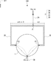
実施の形態1にかかるアンテナ100について説明する。本実施の形態では、アンテナ100はマイクロストリップラインによって給電される円形パッチアンテナとして構成される。図1は、実施の形態1にかかるアンテナ100の構成を模式的に示す上面図である。アンテナ100は、パッチ1及び給電回路2を有する。給電回路2は、2つの偏波が誘起されるポートA及びポートBを有する。 ここで、2つの偏波のうちの一方の偏波面と2つの偏波のうちの他方の偏波面とは、互いに直交していてもよい。また、当然のことながら、2つの偏波の波長は同じである。なお、2つの偏波の一方を第1の偏波とも称し、2つの偏波の他方を第2の偏波とも称する。ポートAでは、2つの偏波の一方であるPol−A(例えば、水平方向のH偏波)が誘起される。ポートBでは、2つの偏波の他方であるPol−B(例えば、垂直方向のV偏波)が誘起される。アンテナ100は、2つの偏波モード用の3つの給電を受ける。
The
ポートA用の給電線2A、2B及び2Cは、マイクロストリップラインとして構成される。3つの給電線2A、2B及び2Cは、それぞれ第1〜第3の給電線とも称する。給電線2Aは、点P1(第1の位置とも称する)において給電線2Bと給電線2Cとに分岐される。給電線2Aの一端はPol−Aの給電源(不図示)と接続され、給電源は給電線2AにPol−Aを供給する。給電線2Aの他端は、点P1で給電線2Bの一端及び給電線2Cの一端と接続される。給電線2Bの他端は、パッチ1の外周上の点P2(第2の位置とも称する)においてパッチ1と接続される。給電線2Cの他端は、パッチ1の外周上の点P3(第3の位置とも称する)においてパッチ1と接続される。本実施の形態では、点P2及びP3は、それぞれパッチの反対側に位置していてもよい。換言すれば、点P2及びP3は、パッチの中心に対して互いに対称な位置に配置されていてもよい。
図1では、インピーダンス整合のため、λ/4変成器10が点P1と給電線2Aとの間に挿入されている。しかし、λ/4変成器10はアンテナ100の必須構成要素ではなく、よって、λ/4変成器10は適宜省略してもよい。
In FIG. 1, a λ / 4
給電線2B及び2Cは、Pol−Aの点P2での位相が、Pol−Aの点P3での位相と比較して、π(180°)だけシフトするように構成される。本実施の形態では、点P1から点P2までの給電線2Bの長さは、点P1から点P3までの給電線2Cの長さよりも、λ/2だけ長い。具体的には、図1〜3においては、給電線2BのY方向部分が、長さがL0の給電線2CのY方向部分よりも、λ/2だけ長い。また、点P2と点P3との間での位相差π(すなわち、λ/2)は、例に過ぎない。つまり、nを0以上の整数とした場合、点P2と点P3との間でπ+2nπ(すなわち、λ/2+nλ)の位相差が生じていれば、原理的にアンテナ100は機能し得る。すなわち、点P2でのPol−Aは、点P3でのPol−Aに対して逆位相となる。
ポートB用の給電線2Dは、マイクロストリップラインとして構成される。ポートB用の給電線2Dは、第4の給電線とも称する。給電線2Dの一端はPol−Bの給電源(不図示)と接続され、給電源は給電線2DにPol−Bを供給する。給電線2Dの他端は、点P4(第4の位置とも称する)でパッチ1と接続される。本実施の形態では、点P4は、パッチ1の外周上での点P2と点P3との中間点に位置している。すなわち、点P4は、パッチ1の外周上で、点P2から反時計回りに、点P3から時計回りに、π/2(90°)だけシフトしている。
The
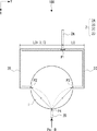
アンテナ100の動作について説明する。図2は、実施の形態1にかかるアンテナ100のPol−Aの電流の流れを模式的に示す上面図である。なお、図2では、簡略化のため、λ/4変成器10を省略している。給電線2Aに供給されたPol−Aは、給電線2Bと給電線2Cとに分岐され、分岐された2つのPol−Aは、それぞれ点P2及びP3へ伝送される。上述したように、給電線2B及び2Cは、点P2におけるPol−Aの位相が点P3におけるPol−Aの位相に対してπ(180°)だけシフトするように構成されている。すなわち、点P2におけるPol−Aは、点P3におけるPol−Aに対して、逆位相である。
The operation of the
その後、点P2からのPol−Aと点P3からPol−AはポートBの点P4へ向かって流れて、合流する。点P2と点P4との間の距離と点P3と点P4との間の距離とは互いに等しいので、点P4では、点P2からのPol−Aは、点P3からのPol−Aに対して逆位相となる。よって、点P2からのPol−Aと点P3からのPol−Aとは、好適にも、点P4で互いに打ち消し合うことができる。 After that, Pol-A from the point P2 and Pol-A from the point P3 flow toward the point P4 of the port B and merge. Since the distance between points P2 and P4 and the distance between points P3 and P4 are equal to each other, at point P4, Pol-A from point P2 is relative to Pol-A from point P3. It will be out of phase. Therefore, Pol-A from the point P2 and Pol-A from the point P3 can preferably cancel each other out at the point P4.
図3は、実施の形態1にかかるアンテナ100のPol−Bの電流の流れを模式的に示す上面図である。なお、図3では、簡略化のため、λ/4変成器10を省略している。給電線2Dに供給されたPol−Bは点P4に流れて、Pol−Bの一部の成分は点P2へ流れ、他の一部の成分は点P3へ流れる。点P2と点P4との間の距離と点P3と点P4との間の距離とは互いに等しいので、点P2における一部成分の位相と点P3における一部成分の位相とは、互いに同じになる。その後、これら一部成分は、点P1に向けて流れて、合流する。上述したように、給電線2B及び2Cは、点P2におけるPol−Aの位相が点P3におけるPol−Aの位相に対してπ(180°)だけシフトするように構成され、かつ、Pol−Bの波長は、Pol−Aの波長と同じである。よって、点P1においては、点P2からのPol−Bの一部成分の位相と点P3からのPol−Bの一部成分の位相とは、互いにπ(180°)だけ異なっている。すなわち、点P1においては、点P2からのPol−Bの一部成分は、点P3からのPol−Bの一部成分に対して、逆位相となる。よって、点P2からのPol−Bの一部成分と点P3からのPol−Bの一部成分とは、好適にも、互いに打ち消し合うことができる。
FIG. 3 is a top view schematically showing the current flow of Pol-B of the
次に、比較例を参照して、アンテナ100の効果について説明する。ここで、実施の形態1にかかるアンテナ及び比較例のアイソレーション改善を観察するため、Ansoft(登録商標)のHFSS (High Frequency Structure Simulator) ver.15をモデリング及びシミュレーションに用いた。設計周波数は5.2GHzである。単一の給電線の場合、マイクロストリップラインとテフロン(登録商標)スペーサとの間の重複を数値的に最適化することで、50Ωのインピーダンス整合が実現される(簡略化のため不図示)。180°位相差の給電線の場合、λ/4変成器がインピーダンス整合のために採用される。
Next, the effect of the
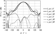
図4は、実施の形態1にかかるアンテナ100のHFSSモデルを模式的に示す斜視図である。図4に示す様に、パッチ1の中心は原点O上に有る。点P1及びP4はX軸上に有り、点P2及びP3はY軸上に有る。Z軸は、パッチ1の主面(X−Y平面)に対して垂直な方向である。図4では、極座標表示において、θは仰角を示し、φは方位角を示す。
FIG. 4 is a perspective view schematically showing an HFSS model of the
図5は、比較例にかかるアンテナ700のHFSSモデルを模式的に示す斜視図である。図5では、アンテナ700のパッチ71の中心は原点O上に有る。給電線のポートAはY軸上に有り、給電線のポートBはX軸上に有る。Z軸は、パッチ1の主面(X−Y平面)に対した垂直な方向である。図5では、極座標表示において、θは仰角を示し、φは方位角を示す。
FIG. 5 is a perspective view schematically showing an HFSS model of the
図6は、アンテナ100及びアンテナ700のポート間のアイソレーションを示す図である。図6では、水平方向の軸は偏波の周波数を表し、鉛直方向の軸はS21パラメータを表す。実線はアンテナ100のポート間のアイソレーションを表し、破線は比較例にかかるアンテナ700のポート間のアイソレーションを表す。図6に示す様に、アンテナ100のポート間のアイソレーションは、アンテナ700と比較して、明らかに改善している。具体的には、アンテナ100のポート間のアイソレーションは10dBよりも大きく、さらに帯域の29%にわたって30dBよりも大きな向上が実現されている。
FIG. 6 is a diagram showing isolation between the ports of the
図7及び8は、比較例にかかるアンテナ700のPol−A及びPol−Bの放射パターンのそれぞれを示す図である。図9及び10は、実施の形態1にかかるアンテナ100のPol−A及びPol−Bの放射パターンのそれぞれを示す図である。水平方向の軸は、図4及び5に示す様に、Z軸と、原点O及びY−Z平面内の半円SC上の点PPを通過する線と、がなす角を表している。鉛直方向の軸は、点PPでのゲインを表している。図7〜10は、0°、45°及び90°の方位角φにおける断面をX−Y平面に投影したものであり、方位角φはX軸からX−Y平面への投影物までの角度である。「C_pol_0°」、「C_pol_45°」及び「C_pol_90°」は、それぞれφ=0°、φ=45°及びφ=90°における断面で観測される主偏波の放射パターンを示している。「X_pol_0°」、「X_pol_45°」及び「X_pol_90°」は、それぞれφ=0°、φ=45°及びφ=90°における断面で観測される交差偏波の放射パターンを示している。
7 and 8 are diagrams showing the radiation patterns of Pol-A and Pol-B of the
図7〜10では、アンテナ100は交差偏波を抑制しており、比較例にかかるアンテナ700でのわずか19dBの交差偏波識別度(Cross Polarization Discrimination:XPD)と比較して、28dBよりも大きなXPDを実現できる。
In FIGS. 7-10, the
上述したように、アンテナ100の構成によれば、2つ偏波のリーク電流による影響を抑制できるアンテナを簡易な構成で実現することができる。よって、本構成によれば、交差偏波、すなわち偏波干渉の影響を好適に抑制できる。
As described above, according to the configuration of the
また、本構成によれば、ポートAの給電線、ポートBの給電線(換言すれば、給電回路)及びパッチに対して、交差していない同一導電層内で給電を行うことができる。故に、アンテナの寸法を好適に削減することができる。さらに、マイクロストリップ給電の2偏波パッチアンテナであるアンテナ100を1つの層に容易にプリントすることができるので、特にプリントアレイ構造を作製する場合に、作製プロセスを簡素化し、かつ、作製コストを低減することができる。
Further, according to this configuration, it is possible to supply power to the feeder line of port A, the feeder line of port B (in other words, the feeder circuit) and the patch in the same conductive layer that does not intersect. Therefore, the dimensions of the antenna can be suitably reduced. Further, since the
実施の形態2
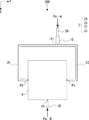
実施の形態1にかかるアンテナ100の変形例について説明する。図11は、実施の形態2にかかるアンテナ200の構成の上面図である。
A modified example of the
アンテナ200は、実施の形態1にかかるアンテナ100のパッチ1をパッチ3に置換した構成を有する。パッチ3は、四角形のパッチである。点P2〜P4は、それぞれパッチ3の異なる頂点に配置されている。
The
本構成でも、点P2から点P4までの距離と、点P3から点P4までの距離とは、互いに等しくなる。よって、アンテナ200では、アンテナ100の場合と同様に、Pol−Aの2つの成分が点P4で打ち消し合うことができ、かつ、Pol−Bの2つの成分が点P1で打ち消し合うことができる。
Even in this configuration, the distance from the point P2 to the point P4 and the distance from the point P3 to the point P4 are equal to each other. Therefore, in the
実施の形態3
実施の形態1にかかるアンテナ100の他の変形例について説明する。図12は、実施の形態3にかかるアンテナ300の構成の上面図である。
Another modification of the
アンテナ300は、実施の形態1にかかるアンテナ100のパッチ1をパッチ4に置換した構成を有する。パッチ4は、四角形のパッチである。点P1〜P3は、それぞれ四角形の異なる辺の中点に配置されている。換言すれば、パッチ4は、パッチ3の中心を通ってパッチ3の主面に対して垂直な軸回りにパッチ3を45°だけ回転させることで構成できる。
The
本構成でも、点P2から点P4までの距離と、点P3から点P4までの距離とは、互いに等しくなる。よって、アンテナ300では、アンテナ100及び200の場合と同様に、Pol−Aの2つの成分が点P4で打ち消し合うことができ、かつ、Pol−Bの2つの成分が点P1で打ち消し合うことができる。
Even in this configuration, the distance from the point P2 to the point P4 and the distance from the point P3 to the point P4 are equal to each other. Therefore, in the
実施の形態4
実施の形態1にかかるアンテナ100を複数有する、実施の形態4にかかるアンテナアレイ400について説明する。図13は、実施の形態4にかかるアンテナアレイ400の構成を示す上面図である。
The
図13に示す例では、アンテナアレイ400は4つのアンテナ100を有する。図13では、4つのアンテナ100を、符号101〜104で示している。
In the example shown in FIG. 13, the
アンテナ101及び102の給電線2Aは、給電線5Aによって相互に接続されている。給電線5Bは、給電線5Aの中央点から給電線5Aと直交する方向に延在している。アンテナ103及び104の給電線2Aは、給電線5Cによって相互に接続されている。給電線5Dは、給電線5Cの中央点から給電線5Cと直交する方向に延在している。ここで、給電線5Cの長さは給電線5Aの長さと同じであり、給電線5Dの長さは給電線5Bの長さと同じであり、給電線5B及び5Dは同じ方向に延在している。給電線5Aの側とは反対側の給電線5Bの端部と、給電線5Cの側とは反対側の給電線5Dの端部とは、給電線5Eによって相互に接続されている。給電線5Fは、給電線5Eの中央点から、給電線5Eと直交する方向に、Pol−A給電点FPA(第1のポートとも称する)まで延在している。また、Pol−A給電点FPAからアンテナ101〜104までの距離は、それぞれ等しい。本構成では、給電源(不図示)がPol−A給電点FPAにPoL−Aを供給してもよい。
The
アンテナ101及び102の給電線2Dは、給電線6Aによって相互に接続されている。給電線6Bは、給電線6Aの中央点から給電線6Aと直交する方向に延在している。アンテナ103及び104の給電線2Dは、給電線6Cによって相互に接続されている。給電線6Dは、給電線6Cの中央点から給電線6Cと直交する方向に延在している。ここで、給電線6Cの長さは給電線6Aの長さと同じであり、給電線6Dの長さは給電線6Bの長さと同じであり、給電線6B及び6Dは同じ方向に延在している。給電線6Aの側とは反対側の給電線6Bの端部と、給電線6Cの側とは反対側の給電線6Dの端部とは、給電線6Eによって相互に接続されている。給電線6Fは、給電線6Eの中央点から、給電線6Eと直交する方向に、Pol−B給電点FPB(第2のポートとも称する)まで延在している。また、Pol−B給電点FPBからアンテナ101〜104までの距離は、それぞれ等しい。本構成では、給電源(不図示)がPol−B給電点FPBにPoL−Bを供給してもよい。
The feeder lines 2D of the
本構成によれば、アンテナ101〜104は、それぞれ、同位相のPol−A及びPol−Bを受け取る。また、アンテナ101〜104は、アンテナ100と同様に、リーク電流を打ち消すことができる。よってアンテナ101〜104は、高いXPDにて同位相の2偏波を放射できるので、アンテナアレイ400は好適に高出力の2偏波を放射できる。
According to this configuration, the
実施の形態5
実施の形態5にかかる無線通信装置600について説明する。図14は、実施の形態5にかかる無線通信装置600の構成を模式的に示すブロック図である。無線通信装置600は、実施の形態1にかかるアンテナ100、ベースバンド部61及びRF部62を有する。ベースバンド部61は、ベースバンド信号S61及び受信信号S64を処理する。RF部62は、ベースバンド部61からのベースバンド信号S61を変調し、変調された送信信号S62をアンテナ100へ出力する。RF部62は、受信信号S63を復調し、復調した受信信号S64をベースバンド部61へ出力する。アンテナ100は、送信信号S62を放射し、かつ、外部アンテナから放射された受信信号S63を受信する。
The
上述したように、本構成によれば、実施の形態1にかかるアンテナ100を用いて外部と通信可能な無線通信装置を具体的に構成できることが理解できる。
As described above, according to this configuration, it can be understood that a wireless communication device capable of communicating with the outside can be specifically configured by using the
その他の実施の形態
なお、本発明は上記実施の形態に限られたものではなく、趣旨を逸脱しない範囲で適宜変更することが可能である。例えば、上述の実施の形態では、上述したパッチの形状は例示に過ぎない。点P2と点P4との間の距離と点P3と点P4との間の距離とが互いに等しい限り、パッチを様々な形状とすることができる。
Other Embodiments The present invention is not limited to the above embodiments, and can be appropriately modified without departing from the spirit. For example, in the embodiment described above, the shape of the patch described above is merely an example. The patch can be in various shapes as long as the distance between points P2 and P4 and the distance between points P3 and P4 are equal to each other.
実施の形態4では、4つのアンテナがアンテナアレイを構成する場合について説明した。しかし、これは例示に過ぎない。よって、アンテナアレイを構成するアンテナの数は、適宜4以外の複数としてもよい。 In the fourth embodiment, a case where four antennas form an antenna array has been described. However, this is just an example. Therefore, the number of antennas constituting the antenna array may be a plurality of antennas other than 4 as appropriate.
上述の実施の形態にかかるアンテナ、アンテナアレイ及び無線通信装置は、無線LAN(Local Area Network)、アクセスポイント及び基地局などのシステムに適用することができ、したがって、端末(携帯端末)との通信に適用することができる。バックホールにおいては、上述の実施の形態にかかるアンテナ、アンテナアレイ及び無線通信装置は、基地局間の通信に適用してもよい。また、上述の実施の形態にかかるアンテナ、アンテナアレイ及び無線通信装置は、LTE(Long Term Evolution)などの様々な通信方法に適用してもよい。 The antenna, antenna array, and wireless communication device according to the above-described embodiment can be applied to a system such as a wireless LAN (Local Area Network), an access point, and a base station, and therefore communicate with a terminal (portable terminal). Can be applied to. In the backhaul, the antenna, the antenna array, and the wireless communication device according to the above-described embodiment may be applied to communication between base stations. Further, the antenna, the antenna array and the wireless communication device according to the above-described embodiment may be applied to various communication methods such as LTE (Long Term Evolution).
以上、実施の形態を参照して本願発明を説明したが、本願発明は上記によって限定されるものではない。本願発明の構成や詳細には、発明のスコープ内で当業者が理解し得る様々な変更をすることができる。 Although the invention of the present application has been described above with reference to the embodiments, the invention of the present application is not limited to the above. Various changes that can be understood by those skilled in the art can be made within the scope of the invention in the configuration and details of the invention of the present application.
この出願は、2017年3月28日に出願された日本出願特願2017−63248を基礎とする優先権を主張し、その開示の全てをここに取り込む。 This application claims priority on the basis of Japanese application Japanese Patent Application No. 2017-63248 filed on March 28, 2017 and incorporates all of its disclosures herein.
1、3、4 パッチ
2 給電回路
2A〜2D、5A〜5F、6A〜6F 給電線
10 λ/4変成器
61 ベースバンド部
62 RF部
100、101〜104、200、300、700 アンテナ
400 アンテナアレイ
600 無線通信装置
1, 3, 4
Claims (12)
第1の偏波を伝送する第1の給電線と、
一端が前記第1の給電線と第1の位置で接続され、他端が前記パッチと第2の位置で接続される第2の給電線と、
一端が前記第1の給電線と前記第1の位置で接続され、他端が前記パッチと第3の位置で接続される第3の給電線と、
一端が前記パッチと第4の位置で接続され、前記第1の偏波と同じ波長の、前記第1の偏波とは異なる第2の偏波を伝送する第4の給電線と、を備え、
前記第2及び第3の給電線は、前記第1の偏波が前記第1の位置から前記第2及び第3の位置に伝送される場合に前記第2の位置における前記第1の偏波が前記第3の位置における前記第1の偏波に対して逆位相となるように構成され、
前記第2の位置と前記第4の位置との間の距離は、前記第3の位置と前記第4の位置との間の距離と等しく、
前記パッチと、前記第1〜第4の給電線とは、同じ層に配置される、
アンテナ。 With patches
The first feeder that transmits the first polarized wave,
A second feeder, one end of which is connected to the first feeder at a first position and the other end of which is connected to the patch at a second position.
A third feeder, one end of which is connected to the first feeder at the first position and the other end of which is connected to the patch at the third position.
One end is connected to the patch at a fourth position and includes a fourth feeder having the same wavelength as the first polarized wave and transmitting a second polarized wave different from the first polarized wave. ,
The second and third feeders have the first polarization at the second position when the first polarization is transmitted from the first position to the second and third positions. Is configured to be out of phase with respect to the first polarization at the third position.
The distance between the second position and said fourth position, rather equal and the distance between the fourth position and the third position,
The patch and the first to fourth feeders are arranged in the same layer.
antenna.
前記第2及び第3の位置の一方における前記第1の偏波の位相は、前記第2及び第3の位置の他方における前記第1の偏波の位相に対して、π+2nπだけ異なる、
請求項1に記載のアンテナ。 n is an integer greater than 0
The phase of the first polarized wave at one of the second and third positions differs from the phase of the first polarized wave at the other of the second and third positions by π + 2nπ.
The antenna according to claim 1.
前記第2及び第3の給電線の一方の長さは、前記第2及び第3の給電線の他方の長さよりも、λ/2+nλだけ長い、
請求項2に記載のアンテナ。 The wavelengths of the first and second polarized waves are λ.
The length of one of the second and third feeders is λ / 2 + nλ longer than the length of the other of the second and third feeders.
The antenna according to claim 2.
前記第2〜第4の位置は、前記円形の外周上に設けられ、
前記第2及び第3の位置は、前記円形の中心に対して対称であり、
前記第4の位置は、前記第2及び第3の位置の間の前記円形の前記外周上の中間点に設けられる、
請求項1乃至3のいずれか一項に記載のアンテナ。 The shape of the patch is circular
The second to fourth positions are provided on the outer circumference of the circle.
The second and third positions are symmetrical with respect to the center of the circle.
The fourth position is provided at an intermediate point on the outer circumference of the circle between the second and third positions.
The antenna according to any one of claims 1 to 3.
前記第2〜第4の位置は、前記四角形のそれぞれ異なる頂点に設けられる、
請求項1乃至3のいずれか一項に記載のアンテナ。 The shape of the patch is quadrangular
The second to fourth positions are provided at different vertices of the quadrangle.
The antenna according to any one of claims 1 to 3.
前記第2〜第4の位置は、前記四角形のそれぞれ異なる辺の中点に設けられる、
請求項1乃至3のいずれか一項に記載のアンテナ。 The shape of the patch is quadrangular
The second to fourth positions are provided at the midpoints of the different sides of the quadrangle.
The antenna according to any one of claims 1 to 3.
請求項1乃至6のいずれか一項に記載のアンテナ。 The planes of polarization of the first and second polarizations are orthogonal to each other.
The antenna according to any one of claims 1 to 6.
請求項1乃至7のいずれか一項に記載のアンテナ。 The first to fourth feeder lines and the patch are continuously formed on the same conductive layer.
The antenna according to any one of claims 1 to 7.
請求項1乃至8のいずれか一項に記載のアンテナ。 Each of the first to fourth feeders is a microstrip line.
The antenna according to any one of claims 1 to 8.
前記第1の偏波の第1のポートと前記第1の給電線のそれぞれとの間の距離が等しくなるように、複数の前記アンテナの前記第1の給電線を前記第1にポートに接続する給電線と、
前記第2の偏波の第2のポートと前記第4の給電線のそれぞれとの間の距離が等しくなるように、前記複数のアンテナの前記第4の給電線を前記第2にポートに接続する給電線と、を備える、
アンテナアレイ。 The antenna according to any one of claims 1 to 9, and the antenna.
The first feeder of the plurality of antennas is connected to the first port so that the distance between the first port of the first polarization and each of the first feeders is equal. Feed line and
The fourth feeder of the plurality of antennas is connected to the second port so that the distance between the second port of the second polarization and each of the fourth feeder is equal. With a feeder line,
Antenna array.
ベースバンド信号を出力し、かつ、復調された受信信号を受信するベースバンド部と、
前記ベースバンド信号を変調し、アンテナを介して変調した信号を送信し、かつ、アンテナを介して受信した信号を復調し、復調した信号を前記ベースバンド部へ出力するRF部と、を備え、
前記変調した信号と変調前の前記受信した信号は、直交偏波信号であり、
前記アンテナは、
パッチと、
第1の偏波を伝送する第1の給電線と、
一端が前記第1の給電線と第1の位置で接続され、他端が前記パッチと第2の位置で接続される第2の給電線と、
一端が前記第1の給電線と前記第1の位置で接続され、他端が前記パッチと第3の位置で接続される第3の給電線と、
一端が前記パッチと第4の位置で接続され、前記第1の偏波と同じ波長の、前記第1の偏波とは異なる第2の偏波を伝送する第4の給電線と、を備え、
前記第2及び第3の給電線は、前記第1の偏波が前記第1の位置から前記第2及び第3の位置に伝送される場合に前記第2の位置における前記第1の偏波が前記第3の位置における前記第1の偏波に対して逆位相となるように構成され、
前記第2の位置と前記第4の位置との間の距離は、前記第3の位置と前記第4の位置との間の距離と等しく、
前記パッチと、前記第1〜第4の給電線とは、同じ層に配置される、
無線通信装置。 With the antenna
The baseband section that outputs the baseband signal and receives the demodulated received signal,
It is provided with an RF unit that modulates the baseband signal, transmits the modulated signal via the antenna, demodulates the signal received via the antenna, and outputs the demodulated signal to the baseband unit.
The modulated signal and the received signal before modulation are orthogonally polarized signals.
The antenna is
With patches
The first feeder that transmits the first polarized wave,
A second feeder, one end of which is connected to the first feeder at a first position and the other end of which is connected to the patch at a second position.
A third feeder, one end of which is connected to the first feeder at the first position and the other end of which is connected to the patch at the third position.
One end is connected to the patch at a fourth position and includes a fourth feeder having the same wavelength as the first polarized wave and transmitting a second polarized wave different from the first polarized wave. ,
The second and third feeders have the first polarization at the second position when the first polarization is transmitted from the first position to the second and third positions. Is configured to be out of phase with respect to the first polarization at the third position.
The distance between the second position and said fourth position, rather equal and the distance between the fourth position and the third position,
The patch and the first to fourth feeders are arranged in the same layer.
Wireless communication device.
第3の給電線の一端を前記第1の位置で前記第1の給電線と接続し、前記第3の給電線の他端を第3の位置で前記パッチと接続し、
前記第1の偏波とは異なり、かつ、前記前記第1の偏波と同じ波長である第2の偏波を伝送する第4の給電線の一端を第4の位置で前記パッチと接続し、
前記第1の偏波は前記第1の位置から前記第2及び第3の位置へ伝送される場合に、前記第2及び第3の給電線は、前記第2の位置における前記第1の偏波が前記第3の位置における前記第1の偏波に対して逆位相となるように構成され、
前記第1の位置と前記第3の位置との間の距離は、前記第2の位置と前記第3の位置との間の距離と等しく、
前記パッチと、前記第1〜第4の給電線とは、同じ層に配置される、
アンテナの構成方法。 One end of the second feeder is connected to the first feeder at the first position to transmit the first polarization, and the other end of the second feeder is connected to the patch at the second position.
One end of the third feeder is connected to the first feeder at the first position, and the other end of the third feeder is connected to the patch at the third position.
One end of a fourth feeder that is different from the first polarized wave and transmits a second polarized wave having the same wavelength as the first polarized wave is connected to the patch at a fourth position. ,
When the first polarization is transmitted from the first position to the second and third positions, the second and third feeders are the first bias at the second position. The wave is configured to be out of phase with the first polarization at the third position.
The distance between the first position and the third position is, rather equal and the distance between the third position and the second position,
The patch and the first to fourth feeders are arranged in the same layer.
How to configure the antenna.
Applications Claiming Priority (3)
| Application Number | Priority Date | Filing Date | Title |
|---|---|---|---|
| JP2017063248 | 2017-03-28 | ||
| JP2017063248 | 2017-03-28 | ||
| PCT/JP2018/004123 WO2018179870A1 (en) | 2017-03-28 | 2018-02-07 | Antenna, configuration method of antenna and wireless communication device |
Publications (2)
| Publication Number | Publication Date |
|---|---|
| JP2020511890A JP2020511890A (en) | 2020-04-16 |
| JP6981475B2 true JP6981475B2 (en) | 2021-12-15 |
Family
ID=63675136
Family Applications (1)
| Application Number | Title | Priority Date | Filing Date |
|---|---|---|---|
| JP2019552297A Active JP6981475B2 (en) | 2017-03-28 | 2018-02-07 | Antenna, antenna configuration method and wireless communication device |
Country Status (3)
| Country | Link |
|---|---|
| US (1) | US11264721B2 (en) |
| JP (1) | JP6981475B2 (en) |
| WO (1) | WO2018179870A1 (en) |
Families Citing this family (17)
| Publication number | Priority date | Publication date | Assignee | Title |
|---|---|---|---|---|
| SG11202008308YA (en) | 2018-03-19 | 2020-09-29 | Pivotal Commware Inc | Communication of wireless signals through physical barriers |
| US10862545B2 (en) | 2018-07-30 | 2020-12-08 | Pivotal Commware, Inc. | Distributed antenna networks for wireless communication by wireless devices |
| US10522897B1 (en) | 2019-02-05 | 2019-12-31 | Pivotal Commware, Inc. | Thermal compensation for a holographic beam forming antenna |
| US10468767B1 (en) | 2019-02-20 | 2019-11-05 | Pivotal Commware, Inc. | Switchable patch antenna |
| US10734736B1 (en) | 2020-01-03 | 2020-08-04 | Pivotal Commware, Inc. | Dual polarization patch antenna system |
| WO2021147945A1 (en) * | 2020-01-22 | 2021-07-29 | 京东方科技集团股份有限公司 | Antenna unit and manufacturing method thereof, display device, and electronic apparatus |
| US11069975B1 (en) | 2020-04-13 | 2021-07-20 | Pivotal Commware, Inc. | Aimable beam antenna system |
| JP2023527384A (en) | 2020-05-27 | 2023-06-28 | ピヴォタル コムウェア インコーポレイテッド | Method for managing RF signal repeater devices for 5G wireless networks |
| US11026055B1 (en) | 2020-08-03 | 2021-06-01 | Pivotal Commware, Inc. | Wireless communication network management for user devices based on real time mapping |
| US11297606B2 (en) | 2020-09-08 | 2022-04-05 | Pivotal Commware, Inc. | Installation and activation of RF communication devices for wireless networks |
| EP4278645A1 (en) | 2021-01-15 | 2023-11-22 | Pivotal Commware, Inc. | Installation of repeaters for a millimeter wave communications network |
| JP2024505881A (en) | 2021-01-26 | 2024-02-08 | ピヴォタル コムウェア インコーポレイテッド | smart repeater system |
| US11451287B1 (en) | 2021-03-16 | 2022-09-20 | Pivotal Commware, Inc. | Multipath filtering for wireless RF signals |
| CN113131186B (en) * | 2021-03-26 | 2022-08-19 | 联想(北京)有限公司 | Ultra-wideband antenna, electronic equipment and signal receiving method |
| AU2022307056A1 (en) | 2021-07-07 | 2024-02-15 | Pivotal Commware, Inc. | Multipath repeater systems |
| US11937199B2 (en) | 2022-04-18 | 2024-03-19 | Pivotal Commware, Inc. | Time-division-duplex repeaters with global navigation satellite system timing recovery |
| CN115189131A (en) * | 2022-07-07 | 2022-10-14 | 隔空(上海)智能科技有限公司 | Antenna three-terminal feed system based on transmit-receive isolation |
Family Cites Families (13)
| Publication number | Priority date | Publication date | Assignee | Title |
|---|---|---|---|---|
| JPS5859605A (en) * | 1981-10-05 | 1983-04-08 | Toshiba Corp | Microstrip antenna |
| JPH02179008A (en) * | 1988-12-28 | 1990-07-12 | Dx Antenna Co Ltd | Planar antenna |
| ZA95797B (en) * | 1994-02-14 | 1996-06-20 | Qualcomm Inc | Dynamic sectorization in a spread spectrum communication system |
| SE515453C2 (en) * | 1999-10-29 | 2001-08-06 | Ericsson Telefon Ab L M | Double-polarized antenna element method for supplying power to two orthogonal polarizations in such an antenna element and method for obtaining said element |
| US6288677B1 (en) * | 1999-11-23 | 2001-09-11 | The United States Of America As Represented By The Administrator Of The National Aeronautics And Space Administration | Microstrip patch antenna and method |
| FR2810164A1 (en) * | 2000-06-09 | 2001-12-14 | Thomson Multimedia Sa | IMPROVEMENT TO ELECTROMAGNETIC WAVE EMISSION / RECEPTION SOURCE ANTENNAS FOR SATELLITE TELECOMMUNICATIONS SYSTEMS |
| JP2003198437A (en) * | 2001-12-28 | 2003-07-11 | Matsushita Electric Ind Co Ltd | Multi-antenna system, receiving method and transmitting method for multi-antenna |
| JP3967637B2 (en) * | 2002-06-21 | 2007-08-29 | 三菱電機株式会社 | Antenna device |
| JP2005286854A (en) * | 2004-03-30 | 2005-10-13 | Kumamoto Technology & Industry Foundation | Antenna having polarization switching function |
| FR2922051A1 (en) | 2007-10-04 | 2009-04-10 | Axess Europ S A | ON-SATELLITE PACKAGE ANTENNA SYSTEM WITH POLARIZATION CONTROL |
| EP2117078B1 (en) * | 2008-05-05 | 2017-07-05 | Nokia Solutions and Networks Oy | Patch antenna element array |
| US9373885B2 (en) * | 2013-02-08 | 2016-06-21 | Ubiquiti Networks, Inc. | Radio system for high-speed wireless communication |
| GB2535216B (en) * | 2015-02-13 | 2019-04-24 | Cambium Networks Ltd | Antenna array assembly using a dielectric film and a ground plate with a contoured surface |
-
2018
- 2018-02-07 WO PCT/JP2018/004123 patent/WO2018179870A1/en active Application Filing
- 2018-02-07 JP JP2019552297A patent/JP6981475B2/en active Active
- 2018-02-07 US US16/497,550 patent/US11264721B2/en active Active
Also Published As
| Publication number | Publication date |
|---|---|
| JP2020511890A (en) | 2020-04-16 |
| US11264721B2 (en) | 2022-03-01 |
| WO2018179870A1 (en) | 2018-10-04 |
| US20210111490A1 (en) | 2021-04-15 |
Similar Documents
| Publication | Publication Date | Title |
|---|---|---|
| JP6981475B2 (en) | Antenna, antenna configuration method and wireless communication device | |
| KR102566993B1 (en) | An antenna module and a radio frequency apparatus including the same | |
| US8854270B2 (en) | Hybrid multi-antenna system and wireless communication apparatus using the same | |
| US10978811B2 (en) | Slot antenna arrays for millimeter-wave communication systems | |
| US8988298B1 (en) | Collocated omnidirectional dual-polarized antenna | |
| US9112260B2 (en) | Microstrip antenna | |
| CN107808998B (en) | Multi-polarization radiation oscillator and antenna | |
| US10148014B2 (en) | Highly isolated monopole antenna system | |
| WO2005034283A2 (en) | Access point antenna for a wireless local area network | |
| KR101252244B1 (en) | Multi antenna | |
| CN111525234A (en) | Dual-polarized antenna and customer front-end equipment | |
| KR20190087270A (en) | Antenna device and electronic apparatus having the same | |
| US20220094075A1 (en) | Dual-feed dual-band interleaved antenna configuration | |
| US11411315B2 (en) | Antenna module and antenna device | |
| US10971803B2 (en) | Omnidirectional antenna system for macro-macro cell deployment with concurrent band operation | |
| WO2017022224A1 (en) | Antenna and wireless communication device | |
| Malviya et al. | MIMO antenna design with low ECC for mmWave | |
| US20230238707A1 (en) | Base station antenna | |
| KR102432378B1 (en) | Multi-fed antenna and device including the same | |
| Ghazizadeh et al. | 60 GHz omni-directional segmented loop antenna | |
| JP2008244733A (en) | Planar array antenna system and radio communication equipment with the same | |
| US20230170601A1 (en) | Electronic device | |
| US20230299491A1 (en) | Antenna module and manufacturing method thereof | |
| KR102158981B1 (en) | Antenna with a symmetrical Feeder Circuit for Improving Antenna Pattern | |
| WO2020133390A1 (en) | Antenna system |
Legal Events
| Date | Code | Title | Description |
|---|---|---|---|
| A621 | Written request for application examination |
Free format text: JAPANESE INTERMEDIATE CODE: A621 Effective date: 20190920 |
|
| A131 | Notification of reasons for refusal |
Free format text: JAPANESE INTERMEDIATE CODE: A131 Effective date: 20201117 |
|
| A02 | Decision of refusal |
Free format text: JAPANESE INTERMEDIATE CODE: A02 Effective date: 20210525 |
|
| A521 | Written amendment |
Free format text: JAPANESE INTERMEDIATE CODE: A523 Effective date: 20210823 |
|
| C60 | Trial request (containing other claim documents, opposition documents) |
Free format text: JAPANESE INTERMEDIATE CODE: C60 Effective date: 20210823 |
|
| A911 | Transfer to examiner for re-examination before appeal (zenchi) |
Free format text: JAPANESE INTERMEDIATE CODE: A911 Effective date: 20210902 |
|
| C21 | Notice of transfer of a case for reconsideration by examiners before appeal proceedings |
Free format text: JAPANESE INTERMEDIATE CODE: C21 Effective date: 20210907 |
|
| TRDD | Decision of grant or rejection written | ||
| A01 | Written decision to grant a patent or to grant a registration (utility model) |
Free format text: JAPANESE INTERMEDIATE CODE: A01 Effective date: 20211019 |
|
| A61 | First payment of annual fees (during grant procedure) |
Free format text: JAPANESE INTERMEDIATE CODE: A61 Effective date: 20211101 |
|
| R150 | Certificate of patent or registration of utility model |
Ref document number: 6981475 Country of ref document: JP Free format text: JAPANESE INTERMEDIATE CODE: R150 |