JP6981237B2 - Vehicle charging system - Google Patents
Vehicle charging system Download PDFInfo
- Publication number
- JP6981237B2 JP6981237B2 JP2017246677A JP2017246677A JP6981237B2 JP 6981237 B2 JP6981237 B2 JP 6981237B2 JP 2017246677 A JP2017246677 A JP 2017246677A JP 2017246677 A JP2017246677 A JP 2017246677A JP 6981237 B2 JP6981237 B2 JP 6981237B2
- Authority
- JP
- Japan
- Prior art keywords
- lock
- charging
- locked state
- vehicle
- state
- Prior art date
- Legal status (The legal status is an assumption and is not a legal conclusion. Google has not performed a legal analysis and makes no representation as to the accuracy of the status listed.)
- Active
Links
Images
Classifications
-
- H—ELECTRICITY
- H01—ELECTRIC ELEMENTS
- H01R—ELECTRICALLY-CONDUCTIVE CONNECTIONS; STRUCTURAL ASSOCIATIONS OF A PLURALITY OF MUTUALLY-INSULATED ELECTRICAL CONNECTING ELEMENTS; COUPLING DEVICES; CURRENT COLLECTORS
- H01R13/00—Details of coupling devices of the kinds covered by groups H01R12/70 or H01R24/00 - H01R33/00
- H01R13/62—Means for facilitating engagement or disengagement of coupling parts or for holding them in engagement
- H01R13/639—Additional means for holding or locking coupling parts together, after engagement, e.g. separate keylock, retainer strap
- H01R13/6397—Additional means for holding or locking coupling parts together, after engagement, e.g. separate keylock, retainer strap with means for preventing unauthorised use
-
- B—PERFORMING OPERATIONS; TRANSPORTING
- B60—VEHICLES IN GENERAL
- B60L—PROPULSION OF ELECTRICALLY-PROPELLED VEHICLES; SUPPLYING ELECTRIC POWER FOR AUXILIARY EQUIPMENT OF ELECTRICALLY-PROPELLED VEHICLES; ELECTRODYNAMIC BRAKE SYSTEMS FOR VEHICLES IN GENERAL; MAGNETIC SUSPENSION OR LEVITATION FOR VEHICLES; MONITORING OPERATING VARIABLES OF ELECTRICALLY-PROPELLED VEHICLES; ELECTRIC SAFETY DEVICES FOR ELECTRICALLY-PROPELLED VEHICLES
- B60L53/00—Methods of charging batteries, specially adapted for electric vehicles; Charging stations or on-board charging equipment therefor; Exchange of energy storage elements in electric vehicles
- B60L53/10—Methods of charging batteries, specially adapted for electric vehicles; Charging stations or on-board charging equipment therefor; Exchange of energy storage elements in electric vehicles characterised by the energy transfer between the charging station and the vehicle
- B60L53/14—Conductive energy transfer
- B60L53/16—Connectors, e.g. plugs or sockets, specially adapted for charging electric vehicles
-
- B—PERFORMING OPERATIONS; TRANSPORTING
- B60—VEHICLES IN GENERAL
- B60K—ARRANGEMENT OR MOUNTING OF PROPULSION UNITS OR OF TRANSMISSIONS IN VEHICLES; ARRANGEMENT OR MOUNTING OF PLURAL DIVERSE PRIME-MOVERS IN VEHICLES; AUXILIARY DRIVES FOR VEHICLES; INSTRUMENTATION OR DASHBOARDS FOR VEHICLES; ARRANGEMENTS IN CONNECTION WITH COOLING, AIR INTAKE, GAS EXHAUST OR FUEL SUPPLY OF PROPULSION UNITS IN VEHICLES
- B60K1/00—Arrangement or mounting of electrical propulsion units
- B60K1/04—Arrangement or mounting of electrical propulsion units of the electric storage means for propulsion
-
- B—PERFORMING OPERATIONS; TRANSPORTING
- B60—VEHICLES IN GENERAL
- B60L—PROPULSION OF ELECTRICALLY-PROPELLED VEHICLES; SUPPLYING ELECTRIC POWER FOR AUXILIARY EQUIPMENT OF ELECTRICALLY-PROPELLED VEHICLES; ELECTRODYNAMIC BRAKE SYSTEMS FOR VEHICLES IN GENERAL; MAGNETIC SUSPENSION OR LEVITATION FOR VEHICLES; MONITORING OPERATING VARIABLES OF ELECTRICALLY-PROPELLED VEHICLES; ELECTRIC SAFETY DEVICES FOR ELECTRICALLY-PROPELLED VEHICLES
- B60L53/00—Methods of charging batteries, specially adapted for electric vehicles; Charging stations or on-board charging equipment therefor; Exchange of energy storage elements in electric vehicles
- B60L53/20—Methods of charging batteries, specially adapted for electric vehicles; Charging stations or on-board charging equipment therefor; Exchange of energy storage elements in electric vehicles characterised by converters located in the vehicle
-
- B—PERFORMING OPERATIONS; TRANSPORTING
- B60—VEHICLES IN GENERAL
- B60L—PROPULSION OF ELECTRICALLY-PROPELLED VEHICLES; SUPPLYING ELECTRIC POWER FOR AUXILIARY EQUIPMENT OF ELECTRICALLY-PROPELLED VEHICLES; ELECTRODYNAMIC BRAKE SYSTEMS FOR VEHICLES IN GENERAL; MAGNETIC SUSPENSION OR LEVITATION FOR VEHICLES; MONITORING OPERATING VARIABLES OF ELECTRICALLY-PROPELLED VEHICLES; ELECTRIC SAFETY DEVICES FOR ELECTRICALLY-PROPELLED VEHICLES
- B60L53/00—Methods of charging batteries, specially adapted for electric vehicles; Charging stations or on-board charging equipment therefor; Exchange of energy storage elements in electric vehicles
- B60L53/60—Monitoring or controlling charging stations
-
- H—ELECTRICITY
- H01—ELECTRIC ELEMENTS
- H01R—ELECTRICALLY-CONDUCTIVE CONNECTIONS; STRUCTURAL ASSOCIATIONS OF A PLURALITY OF MUTUALLY-INSULATED ELECTRICAL CONNECTING ELEMENTS; COUPLING DEVICES; CURRENT COLLECTORS
- H01R13/00—Details of coupling devices of the kinds covered by groups H01R12/70 or H01R24/00 - H01R33/00
- H01R13/62—Means for facilitating engagement or disengagement of coupling parts or for holding them in engagement
- H01R13/639—Additional means for holding or locking coupling parts together, after engagement, e.g. separate keylock, retainer strap
-
- H—ELECTRICITY
- H01—ELECTRIC ELEMENTS
- H01R—ELECTRICALLY-CONDUCTIVE CONNECTIONS; STRUCTURAL ASSOCIATIONS OF A PLURALITY OF MUTUALLY-INSULATED ELECTRICAL CONNECTING ELEMENTS; COUPLING DEVICES; CURRENT COLLECTORS
- H01R13/00—Details of coupling devices of the kinds covered by groups H01R12/70 or H01R24/00 - H01R33/00
- H01R13/64—Means for preventing incorrect coupling
-
- B—PERFORMING OPERATIONS; TRANSPORTING
- B60—VEHICLES IN GENERAL
- B60L—PROPULSION OF ELECTRICALLY-PROPELLED VEHICLES; SUPPLYING ELECTRIC POWER FOR AUXILIARY EQUIPMENT OF ELECTRICALLY-PROPELLED VEHICLES; ELECTRODYNAMIC BRAKE SYSTEMS FOR VEHICLES IN GENERAL; MAGNETIC SUSPENSION OR LEVITATION FOR VEHICLES; MONITORING OPERATING VARIABLES OF ELECTRICALLY-PROPELLED VEHICLES; ELECTRIC SAFETY DEVICES FOR ELECTRICALLY-PROPELLED VEHICLES
- B60L2210/00—Converter types
- B60L2210/30—AC to DC converters
-
- B—PERFORMING OPERATIONS; TRANSPORTING
- B60—VEHICLES IN GENERAL
- B60L—PROPULSION OF ELECTRICALLY-PROPELLED VEHICLES; SUPPLYING ELECTRIC POWER FOR AUXILIARY EQUIPMENT OF ELECTRICALLY-PROPELLED VEHICLES; ELECTRODYNAMIC BRAKE SYSTEMS FOR VEHICLES IN GENERAL; MAGNETIC SUSPENSION OR LEVITATION FOR VEHICLES; MONITORING OPERATING VARIABLES OF ELECTRICALLY-PROPELLED VEHICLES; ELECTRIC SAFETY DEVICES FOR ELECTRICALLY-PROPELLED VEHICLES
- B60L2250/00—Driver interactions
- B60L2250/16—Driver interactions by display
-
- B—PERFORMING OPERATIONS; TRANSPORTING
- B60—VEHICLES IN GENERAL
- B60L—PROPULSION OF ELECTRICALLY-PROPELLED VEHICLES; SUPPLYING ELECTRIC POWER FOR AUXILIARY EQUIPMENT OF ELECTRICALLY-PROPELLED VEHICLES; ELECTRODYNAMIC BRAKE SYSTEMS FOR VEHICLES IN GENERAL; MAGNETIC SUSPENSION OR LEVITATION FOR VEHICLES; MONITORING OPERATING VARIABLES OF ELECTRICALLY-PROPELLED VEHICLES; ELECTRIC SAFETY DEVICES FOR ELECTRICALLY-PROPELLED VEHICLES
- B60L2250/00—Driver interactions
- B60L2250/24—Driver interactions by lever actuation
-
- H—ELECTRICITY
- H01—ELECTRIC ELEMENTS
- H01R—ELECTRICALLY-CONDUCTIVE CONNECTIONS; STRUCTURAL ASSOCIATIONS OF A PLURALITY OF MUTUALLY-INSULATED ELECTRICAL CONNECTING ELEMENTS; COUPLING DEVICES; CURRENT COLLECTORS
- H01R2201/00—Connectors or connections adapted for particular applications
- H01R2201/26—Connectors or connections adapted for particular applications for vehicles
-
- Y—GENERAL TAGGING OF NEW TECHNOLOGICAL DEVELOPMENTS; GENERAL TAGGING OF CROSS-SECTIONAL TECHNOLOGIES SPANNING OVER SEVERAL SECTIONS OF THE IPC; TECHNICAL SUBJECTS COVERED BY FORMER USPC CROSS-REFERENCE ART COLLECTIONS [XRACs] AND DIGESTS
- Y02—TECHNOLOGIES OR APPLICATIONS FOR MITIGATION OR ADAPTATION AGAINST CLIMATE CHANGE
- Y02T—CLIMATE CHANGE MITIGATION TECHNOLOGIES RELATED TO TRANSPORTATION
- Y02T10/00—Road transport of goods or passengers
- Y02T10/60—Other road transportation technologies with climate change mitigation effect
- Y02T10/70—Energy storage systems for electromobility, e.g. batteries
-
- Y—GENERAL TAGGING OF NEW TECHNOLOGICAL DEVELOPMENTS; GENERAL TAGGING OF CROSS-SECTIONAL TECHNOLOGIES SPANNING OVER SEVERAL SECTIONS OF THE IPC; TECHNICAL SUBJECTS COVERED BY FORMER USPC CROSS-REFERENCE ART COLLECTIONS [XRACs] AND DIGESTS
- Y02—TECHNOLOGIES OR APPLICATIONS FOR MITIGATION OR ADAPTATION AGAINST CLIMATE CHANGE
- Y02T—CLIMATE CHANGE MITIGATION TECHNOLOGIES RELATED TO TRANSPORTATION
- Y02T10/00—Road transport of goods or passengers
- Y02T10/60—Other road transportation technologies with climate change mitigation effect
- Y02T10/7072—Electromobility specific charging systems or methods for batteries, ultracapacitors, supercapacitors or double-layer capacitors
-
- Y—GENERAL TAGGING OF NEW TECHNOLOGICAL DEVELOPMENTS; GENERAL TAGGING OF CROSS-SECTIONAL TECHNOLOGIES SPANNING OVER SEVERAL SECTIONS OF THE IPC; TECHNICAL SUBJECTS COVERED BY FORMER USPC CROSS-REFERENCE ART COLLECTIONS [XRACs] AND DIGESTS
- Y02—TECHNOLOGIES OR APPLICATIONS FOR MITIGATION OR ADAPTATION AGAINST CLIMATE CHANGE
- Y02T—CLIMATE CHANGE MITIGATION TECHNOLOGIES RELATED TO TRANSPORTATION
- Y02T90/00—Enabling technologies or technologies with a potential or indirect contribution to GHG emissions mitigation
- Y02T90/10—Technologies relating to charging of electric vehicles
- Y02T90/12—Electric charging stations
-
- Y—GENERAL TAGGING OF NEW TECHNOLOGICAL DEVELOPMENTS; GENERAL TAGGING OF CROSS-SECTIONAL TECHNOLOGIES SPANNING OVER SEVERAL SECTIONS OF THE IPC; TECHNICAL SUBJECTS COVERED BY FORMER USPC CROSS-REFERENCE ART COLLECTIONS [XRACs] AND DIGESTS
- Y02—TECHNOLOGIES OR APPLICATIONS FOR MITIGATION OR ADAPTATION AGAINST CLIMATE CHANGE
- Y02T—CLIMATE CHANGE MITIGATION TECHNOLOGIES RELATED TO TRANSPORTATION
- Y02T90/00—Enabling technologies or technologies with a potential or indirect contribution to GHG emissions mitigation
- Y02T90/10—Technologies relating to charging of electric vehicles
- Y02T90/14—Plug-in electric vehicles
Landscapes
- Engineering & Computer Science (AREA)
- Transportation (AREA)
- Mechanical Engineering (AREA)
- Power Engineering (AREA)
- Computer Security & Cryptography (AREA)
- Chemical & Material Sciences (AREA)
- Combustion & Propulsion (AREA)
- Electric Propulsion And Braking For Vehicles (AREA)
- Arrangement Or Mounting Of Propulsion Units For Vehicles (AREA)
- Details Of Connecting Devices For Male And Female Coupling (AREA)
Description
本開示は、車外の充電ケーブルから供給される電力を用いて車載の蓄電装置を充電する外部充電が可能な車両の充電システムに関する。 The present disclosure relates to a vehicle charging system capable of external charging that charges an in-vehicle power storage device using electric power supplied from a charging cable outside the vehicle.
車外の充電ケーブルから供給される電力を用いて車載の蓄電装置を充電する外部充電が可能な車両には、第三者の悪戯等によって充電ケーブルの充電コネクタと車両のインレットとが係合されている状態を解除されないようにするためのロック装置を備えるものが存在する。ロック装置は、充電コネクタをインレットから取り外し不能なロック状態と、充電コネクタをインレットから取り外し可能なアンロック状態とを切り替え可能に構成される。 For vehicles that can be externally charged to charge the in-vehicle power storage device using the power supplied from the charging cable outside the vehicle, the charging connector of the charging cable and the inlet of the vehicle are engaged by mischief of a third party or the like. Some are equipped with a locking device to prevent the state from being released. The lock device is configured to be able to switch between a locked state in which the charging connector cannot be removed from the inlet and an unlocked state in which the charging connector can be removed from the inlet.
特開2016−85786公報(特許文献1)には、外部充電が可能な車両に搭載された充電コネクタのロック装置が開示されている。このロック装置は、インレットと充電コネクタとが接続されると、車両の制御装置による制御によってアンロック状態からロック状態に切り替えられる。 Japanese Patent Application Laid-Open No. 2016-85786 (Patent Document 1) discloses a lock device for a charging connector mounted on a vehicle capable of external charging. When the inlet and the charging connector are connected, this locking device is switched from the unlocked state to the locked state by the control of the vehicle control device.
上述のロック装置を備える車両においては、ロック装置がアンロック状態である場合に外部充電が実行されると、所定値以上の電流が流れている状態で充電コネクタがインレットから取り外されるという状況が想定される。このような状況を回避するために、ロック装置がロック状態であるときに限り外部充電を許可する車両の充電システムが考えられる。 In a vehicle equipped with the above-mentioned locking device, if external charging is executed when the locking device is in the unlocked state, it is assumed that the charging connector is removed from the inlet while a current exceeding a predetermined value is flowing. Will be done. In order to avoid such a situation, a vehicle charging system that allows external charging only when the locking device is locked can be considered.
しかしながら、ユーザが上記の充電システムを搭載した車両の外部充電を行なう場合に、ロック装置の故障等により、制御装置による制御によってロック装置をロック状態に切り替えできないという状況も想定される。このような場合、ユーザの意図に反して外部充電が許可されなくなることが懸念される。 However, when the user externally charges the vehicle equipped with the above charging system, it is assumed that the lock device cannot be switched to the locked state by the control of the control device due to a failure of the lock device or the like. In such a case, there is a concern that external charging will not be permitted against the intention of the user.
本開示は、上記課題を解決するためになされたものであり、その目的は、車両の制御装置による制御によってロック装置をロック状態に切り替えできない場合においても、外部充電を可能にすることである。 The present disclosure has been made to solve the above problems, and an object thereof is to enable external charging even when the lock device cannot be switched to the locked state by the control of the vehicle control device.
この開示に係る車両の充電システムは、車外の充電ケーブルから供給される電力を用いて車載の蓄電装置を充電可能な車両の充電システムである。充電ケーブルの先端に設けられた充電コネクタと接続可能に構成されたインレットと、充電コネクタをインレットから取り外し不能なロック状態と、充電コネクタをインレットから取り外し可能なアンロック状態との切り替えが可能なロック装置と、ロック状態を検出する検出装置と、蓄電装置の充電を制御する制御装置とを備える。ロック装置は、アンロック状態からロック状態への切り替えを指示するロック指令を制御装置から受けることによって、または、ユーザによる手動操作によって、アンロック状態をロック状態に切り替え可能に構成される。制御装置は、ロック装置にロック指令を送信した後において、ロック状態が検出された場合は蓄電装置の充電を許可し、ロック状態が検出されなかった場合は蓄電装置の充電を不許可とする。 The vehicle charging system according to this disclosure is a vehicle charging system capable of charging an in-vehicle power storage device using electric power supplied from a charging cable outside the vehicle. A lock that can be switched between an inlet that can be connected to the charging connector provided at the end of the charging cable, a locked state in which the charging connector cannot be removed from the inlet, and an unlocked state in which the charging connector can be removed from the inlet. It includes a device, a detection device that detects a locked state, and a control device that controls charging of the power storage device. The lock device is configured to be able to switch the unlocked state to the locked state by receiving a lock command instructing the switching from the unlocked state to the locked state from the control device or by a manual operation by the user. After transmitting the lock command to the lock device, the control device permits charging of the power storage device when the lock state is detected, and disallows charging of the power storage device when the lock state is not detected.
上記構成によれば、ロック装置の故障等によって、制御装置からのロック指令によるロック状態への切り替えが不能な場合であっても、ユーザの手動操作によってロック状態に切り替えられることによって、ロック状態が検出されて外部充電が許可される。 According to the above configuration, even if it is impossible to switch to the locked state by the lock command from the control device due to a failure of the lock device, the locked state can be changed by manually operating the user. Detected and allowed for external charging.
好ましくは、制御装置は、ロック指令を送信した後に蓄電装置の充電を不許可とした場合において、ロック状態が検出されたときは、蓄電装置の充電を許可する。 Preferably, when the control device disallows charging of the power storage device after transmitting the lock command, when the locked state is detected, the control device permits charging of the power storage device.
上記構成によれば、ロック指令を送信した後に外部充電が不許可とされた場合でも、その後に、ユーザの手動操作によってロック状態に切り替えられることによって、ロック状態が検出されて外部充電が許可される。 According to the above configuration, even if the external charging is disallowed after the lock command is transmitted, the locked state is detected and the external charging is permitted by switching to the locked state by the user's manual operation after that. To.
好ましくは、制御装置は、ロック指令を送信した後に蓄電装置の充電を不許可とした場合において、ロック装置にロック指令を再度送信する。 Preferably, the control device retransmits the lock command to the lock device when charging of the power storage device is disallowed after the lock command is transmitted.
上記構成によれば、ロック指令を送信した後に外部充電が不許可とされた場合でも、その後に、再度のロック指令を送信によってロック状態が検出されると外部充電が許可される。ロック装置がロック状態に切り替わらなかった原因がロック装置の故障等ではなく、ノイズ等によってロック装置がロック指令を誤認識したために、偶発的にアンロック状態からロック状態に切り替わらなかったような場合もあり得る。再度ロック指令を送信することで、送信時に上記の偶発的状況が解消されていれば、ロック装置はロック状態に切り替えられ、外部充電が許可される。 According to the above configuration, even if the external charging is disallowed after the lock command is transmitted, the external charging is permitted when the locked state is detected by transmitting the lock command again. The reason why the lock device did not switch to the locked state is not the failure of the lock device, but the lock device erroneously recognized the lock command due to noise, etc., and the lock device did not accidentally switch from the unlocked state to the locked state. possible. By transmitting the lock command again, if the above-mentioned accidental situation is resolved at the time of transmission, the lock device is switched to the locked state and external charging is permitted.
好ましくは、情報を報知する報知装置をさらに備える。制御装置は、ロック指令を送信した後に蓄電装置の充電を不許可とした場合において、ユーザによる手動操作によるロック状態への切り替えが可能であることを示す情報を報知装置に報知させる。 Preferably, the notification device for notifying the information is further provided. When the charging of the power storage device is disallowed after the lock command is transmitted, the control device notifies the notification device of information indicating that the user can manually switch to the locked state.
上記構成によれば、たとえば、ロック装置の故障等によって、ロック指令によるロック状態への切り替えが不能な場合に、ユーザの手動操作によってロック状態に切り替えることが可能であることをユーザに報知することができる。これによって、ユーザは、手動操作によってロック装置をロック状態へ切り替えられることを認識でき、ユーザの利便性が向上される。 According to the above configuration, when it is impossible to switch to the locked state by a lock command due to, for example, a failure of the lock device, the user is notified that the locked state can be switched by manual operation of the user. Can be done. As a result, the user can recognize that the locking device can be switched to the locked state by manual operation, and the convenience of the user is improved.
本開示によれば、車両の制御装置による制御によってロック装置をロック状態へ切り替えできない場合においても、外部充電を可能にすることができる。 According to the present disclosure, even when the lock device cannot be switched to the locked state by the control of the vehicle control device, external charging can be enabled.
以下、本実施の形態について、図面を参照しながら詳細に説明する。なお、図中同一または相当部分には同一符号を付してその説明は繰り返さない。 Hereinafter, the present embodiment will be described in detail with reference to the drawings. The same or corresponding parts in the drawings are designated by the same reference numerals and the description thereof will not be repeated.
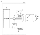
図1は、本実施の形態に係る充電システムを備えた車両1の全体構成を概略的に示す図である。車両1は、蓄電装置10と、AC(交流)インレット220と、リッド2と、電力変換装置40と、ECU(Electronic Control Unit)100と、表示装置70とを備える。
FIG. 1 is a diagram schematically showing an overall configuration of a vehicle 1 provided with a charging system according to the present embodiment. The vehicle 1 includes a
蓄電装置10は、充放電可能に構成される。蓄電装置10は、たとえば、ニッケル水素電池やリチウムイオン電池等の二次電池を含んで構成される。
The
車両1は、蓄電装置10に蓄えられた電力を用いて走行可能な電動車両(ハイブリッド自動車、電気自動車など)である。車両1は、車両外部の交流電源に接続された充電ケーブル(図2)の充電コネクタ410から受電可能に構成される。
The vehicle 1 is an electric vehicle (hybrid vehicle, electric vehicle, etc.) capable of traveling by using the electric power stored in the
インレット220は、充電コネクタ410に接続可能に構成される。リッド2は、インレット220に対して開閉可能に構成される。リッド2が開かれ、かつ充電コネクタ410がインレット220に接続された状態である場合には、車両1は、充電コネクタ410から供給される交流電力を用いて蓄電装置10を充電することができる。
The
電力変換装置40は、インレット220と蓄電装置10との間に接続される。電力変換装置40は、ECU100からの制御信号によって作動し、充電コネクタ410からインレット220が受けた交流電力を蓄電装置10に充電可能な電力に変換して蓄電装置10に供給する。これにより、充電コネクタ410から供給される交流電力を用いて蓄電装置10が充電される。
The
ECU100は、蓄電装置10の充電を制御する。ECU100は、ロック装置50がロック状態の場合は外部充電を許可し、ロック装置50がアンロック状態の場合は外部充電を許可しない。
The ECU 100 controls charging of the
また、ECU100は、充電コネクタ410とインレット220の接続を検出すると、ロック装置50をアンロック状態からロック状態への切り替えを指示するロック指令をロック装置50に送信する。ECU100は、外部充電の終了や、ユーザの所定操作等によって、ロック装置50をロック状態からアンロック状態への切り替えを指示するアンロック指令をロック装置50に送信する。
Further, when the ECU 100 detects the connection between the
さらに、車両1は、充電コネクタ410用のロック装置50を含むコネクタロック装置80を備える。ロック装置50は、コネクタロックピン52と、アクチュエータ51とを含む。なお、コネクタロック装置80が備えるロック装置50以外のその他の構成についての詳細は、後述する。
Further, the vehicle 1 includes a
コネクタロックピン52は、充電コネクタ410をインレット220から取り外し不能なロック状態にしたり、充電コネクタ410をインレット220から取り外し可能なアンロック状態にしたりするための部材である。コネクタロックピン52は、ピン軸方向に移動可能に構成される。
The
アクチュエータ51は、コネクタロックピン52をピン軸方向に移動させるための電動アクチュエータ(モータ)である。アクチュエータ51にある方向(ロック方向)に電流が流れると、アクチュエータ51はコネクタロックピン52を予め定められたロック位置まで移動させるロック動作を行なう。これにより、充電コネクタ410がロック状態となる。アクチュエータ51にロック方向とは逆方向(アンロック方向)に電流が流れると、アクチュエータ51はコネクタロックピン52を予め定められたアンロック位置まで移動させるアンロック動作を行なう。これにより、充電コネクタ410がアンロック状態となる。なお、後述するように、アクチュエータ51は、ユーザの手動の操作によってもロック動作およびアンロック動作を行なうことができる。
The
表示装置70は、ECU100から後述する情報等を受信して、受信した各種の情報を表示する。本実施の形態においては、車両1が表示装置70を備える例について説明するが、たとえば、車両1が備えたナビゲーション装置に表示装置70の機能を持たせてもよい。なお、本実施の形態に係る表示装置70は、本開示に係る「報知装置」の一例に相当する。
The
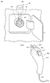
図2は、インレット220周辺および充電ケーブル400の構造を示す図である。本実施の形態においては、ロック装置50は、インレット220の上方(インレット220の近傍)に設けられる。
FIG. 2 is a diagram showing the structure around the
充電ケーブル400は、充電コネクタ410と、交流電力線440とを備える。充電ケーブル400は、交流電力線440を介して車両1外部の電源からの電力をインレット220に供給する。
The charging
充電コネクタ410の先端には接続部413が設けられ、インレット220に電気的に導通可能に接続される。充電コネクタ410には、リンク411が設けられている。このリンク411は、軸412の周りに回転自在に取り付けられ、一端にインレット220の突起221と係合する凸部が設けられ、他端には押しボタン415が設けられている。なお、リンク411は、バネ414によって充電コネクタ410の本体に対して弾性的に付勢されている(図3および図4参照)。充電コネクタ410は、充電ケーブル400の接続を検出するための検出回路(図示しない)を備える。充電コネクタ410とインレット220とが電気的に接続されると、充電ケーブル400が電気的に接続された状態を示す接続信号(プロキシメトリディテクション信号)PISWがインレット220を介してECU100に送信される。ECU100は、PISWを受信すると、充電コネクタ410とインレット220とが電気的に接続された状態であると判定する。
A
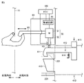
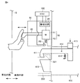
図3および図4は、図2におけるIII−III断面図である。図3には、ロック装置50がロック状態である場合が示されている。図4には、ロック装置50がアンロック状態である場合が示されている。図3および図4を用いて本実施の形態に係るロック装置50を含むコネクタロック装置80について説明する。
3 and 4 are cross-sectional views taken along the line III-III in FIG. FIG. 3 shows a case where the
コネクタロック装置80は、ロック装置50と、駆動回路20と、手動操作部材90と、ロック検出スイッチR3とを備える。上述のとおり、ロック装置50は、アクチュエータ51とコネクタロックピン52とを含む。
The
駆動回路20は、ECU100からの受けるロック装置の状態を切り替えを指示する指令に基づいて、ロック装置50のアクチュエータ51を駆動させるための電流を生成し、アクチュエータ51に電流を流す。具体的には、駆動回路20は、ECU100から、ロック装置50のアンロック状態からロック状態への切り替えを指示するロック指令を受けると、アクチュエータ51にロック方向に電流を流す。一方、駆動回路20は、ECU100から、ロック装置50のロック状態からアンロック状態への切り替えを指示するアンロック指令を受けると、アクチュエータ51にアンロック方向に電流を流す。
The
手動操作部材90は、手動操作部材90のユーザの操作(手動操作)によって、アクチュエータ51のロック動作およびアンロック動作を行なうための操作レバーである。手動操作部材90は、非常時用の操作レバーとして用いられる。非常時とは、ロック装置50の故障等によって、ECU100からのロック指令またはアンロック指令により、ロック装置50の状態を切り替えできないような場合である。手動操作部材90は、図3および図4に示されるように、車両1のインナーパネル15に設けられた開口部からユーザが手を入れ込んで操作できるように設けられている。本実施の形態においては、手動操作部材90を図3における車両内部方向に操作させることによって、アクチュエータ51にロック動作を行させる。一方、手動操作部材90を図3における車両外部方向に操作させることによって、アクチュエータ51にアンロック動作をさせる。
The
本実施の形態においては、一例として、図示しないが手動操作部材90にはアクチュエータ(モータ)51と係合してアクチュエータ51を手動操作可能なようにギアが設けられている。このギアは、上述の手動操作部材90を図3における車両内部方向へ操作することによって、コネクタロックピン52をロック方向へ移動させるようにアクチュエータ51を動作させる。また、このギアは、上述の手動操作部材90を図3における車両外部方向へ操作することによって、コネクタロックピン52をアンロック方向へ移動させるようにアクチュエータ51を動作させる。
In the present embodiment, as an example, although not shown, the
なお、本実施の形態においては、手動操作部材90の操作によって操作される対象がアクチュエータ51である例を示したが、手動操作部材90の操作によってロック装置50のロック状態およびアンロック状態を切り替え可能であればよい。たとえば、ロック装置50に各々がコネクタロックピン52のロック状態およびアンロック状態とを切り替え可能な電動アクチュエータと手動アクチュエータとを備えてもよい。この場合、ECU100からの切替指令によって駆動回路20を介して電動アクチュエータが動作され、一方で、手動操作部材90の操作によって手動アクチュエータが動作され、ロック装置50のロック状態およびアンロック状態が切り替えられる。
In the present embodiment, an example is shown in which the target operated by the operation of the manually operated
コネクタロック装置80には、ロック装置50のロック状態を検出するためのロック検出スイッチR3が設けられている。ロック検出スイッチR3は、コネクタロックピン52がロック位置に移動する際に(ロック動作)、コネクタロックピン52によって押されるように配置されている。図3には、コネクタロックピン52によってロック検出スイッチR3が押されている状態が示されている。ロック検出スイッチR3は、コネクタロックピン52によって押されると閉状態となり、ロック状態である間は閉状態(ON状態)が維持されるように配置されている。
The
ロック検出スイッチR3は、コネクタロックピン52がアンロック位置に移動すると(アンロック動作)、コネクタロックピン52と接触しなくなるように配置されている。また、図4には、コネクタロックピン52によってロック検出スイッチR3が押されていない状態が示されている。ロック検出スイッチR3は、コネクタロックピン52によって押されていないと開状態となり、アンロック状態である間は開状態(OFF状態)が維持されるように配置されている。
The lock detection switch R3 is arranged so as not to come into contact with the
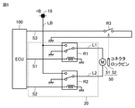
図5は、駆動回路20およびロック検出スイッチR3の構成の一例を示す図である。この駆動回路20は、電源18からの電力が供給される電源線LBと、第1電線L1と、第1電線L1の一方の端部に接続されたロックリレーR1と、第2電線L2と、第2電線L2の一方の端部に接続されたアンロックリレーR2とを含む。
FIG. 5 is a diagram showing an example of the configuration of the
ロックリレーR1は、信号線S1を介してECU100から送信されるロック指令に従って、第1電線L1の一方の端部の接続先を電源線LBおよびグランド(基準電位を有する部位)のどちらかに切替可能に構成される。
The lock relay R1 switches the connection destination of one end of the first electric wire L1 to either the power line LB or the ground (a portion having a reference potential) according to a lock command transmitted from the
アンロックリレーR2は、信号線S2を介してECU100から送信されるアンロック指令に従って、第2電線L2の一方の端部の接続先を電源線LBおよびグランドのどちらかに切替可能に構成される。
The unlock relay R2 is configured so that the connection destination of one end of the second electric wire L2 can be switched to either the power line LB or the ground according to the unlock command transmitted from the
ロックリレーR1およびアンロックリレーR2は、第1電線L1および第2電線L2のいずれか一方が電源線LBに接続され他方がグランドに接続されるように、互いに連動して制御される。 The lock relay R1 and the unlock relay R2 are controlled in conjunction with each other so that either one of the first electric wire L1 and the second electric wire L2 is connected to the power line LB and the other is connected to the ground.
アクチュエータ51は、第1電線L1の他方の端部と第2電線L2の他方の端部との間に接続される。ロックリレーR1が第1電線L1と電源線LBとを接続する状態になると、第1電線L1からアクチュエータ51にロック方向の電流が流れ、コネクタロックピン52のロック動作が行なわれる。一方、アンロックリレーR2が第2電線L2と電源線LBとを接続する状態になると、第2電線L2からアクチュエータ51にアンロック方向(ロック方向は逆方向)の電流が流れ、コネクタロックピン52のアンロック動作が行なわれる。
The
ロック検出スイッチR3は、信号線S3を介してECU100に接続されている。ロック検出スイッチR3は、上述のとおり、コネクタロックピン52のロック動作が行われると、コネクタロックピン52の動作によって、閉状態にされる。一方、ロック検出スイッチR3は、コネクタロックピン52のアンロック動作が行われると、コネクタロックピン52の動作によって、開状態にされる。
The lock detection switch R3 is connected to the
ECU100は、信号線S3を介して取得する電位によって、ロック検出スイッチR3の開閉状態を検出する。ECU100は、ロック検出スイッチR3の開状態を検出するとロック装置50はアンロック状態であると判定する。ECU100は、ロック検出スイッチR3の閉状態を検出するとロック装置50はロック状態であると判定する。なお、本実施の形態に係るロック検出スイッチR3は、本開示に係る「検出装置」の一例に相当する。
The
上記のような車両1においては、ロック装置がロック状態である場合には外部充電が許可され、ロック装置がアンロック状態である場合には外部充電が不許可とされる。これによって、外部充電中に充電コネクタがインレットから取り外されることを防止している。 In the vehicle 1 as described above, external charging is permitted when the lock device is in the locked state, and external charging is not permitted when the lock device is in the unlocked state. This prevents the charging connector from being removed from the inlet during external charging.
しかしながら、ロック装置の故障等により、ECU100からのロック指令によってロック装置50ロック状態に切り替えできないという状況も想定される。このような場合、ユーザの意図に反して外部充電が開始されなくなることが懸念される。
However, it is assumed that the
本実施の形態に係るECU100は、ロック指令を送信した後に、外部充電を不許可とした場合において、手動操作部材90の操作による手動ロックが可能な旨、および、手動操作部材90の操作による手動ロックの方法を表示装置70に表示させる。ECU100は、ユーザの手動操作部材90の操作によってロック装置50がロック状態に切り替えられ、ロック装置のロック状態を検出すると、外部充電を許可する。これによって、ロック装置50の故障等によりロック指令によるロック状態への切り替えができない場合においても、手動操作部材90の操作によってロック装置50をロック状態にすることによって、外部充電を可能にすることができる。
The
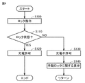
図6は、本実施の形態に係る、外部充電時にECU100で実行される処理を示すフローチャートである。このフローチャートは、充電コネクタ410とインレット220との接続が検出される毎に実行される。なお、図6に示すフローチャートに示される各ステップは、ECU100によるソフトウェア処理によって実現されるが、その一部がECU100内に作製されたハードウェア(電気回路)によって実現されてもよい。図7に示すフローチャートに示される各ステップも同様である。
FIG. 6 is a flowchart showing a process executed by the
ECU100は、充電コネクタ410とインレット220との接続が検出されると、ロック装置50にロック指令を送信する(ステップ100、以下ステップを「S」と略す)。
When the connection between the charging
ECU100は、ロック指令によってロック装置50がロック状態に切り替わったか(コネクタロックピン52がロック位置に移動したか)否かを判定する(S110)。この判定は、上述のとおり、ECU100がロック検出スイッチR3が開状態および閉状態のいずれの状態を検出したかによって判定される。
The
ECU100は、S110においてロック装置50がロック状態であると判定すると(S110においてYES)、外部充電を許可する(S120)。
When the
ECU100は、S110においてロック装置50がロック状態に切り替わらずに、アンロック状態であると判定すると(S110においてNO)、外部充電を不許可とする(S130)。ロック装置50がロック指令によってロック状態に切り替わらないのは、ロック装置50の故障等が考えられる。
When the
また、ECU100は、外部充電を不許可とすると、手動操作部材90の操作による手動ロックが可能な旨、および、手動操作部材90の操作による手動ロックの方法を表示装置70に表示させる(S140)。手動操作部材90は、非常時用の操作レバーとして設けられている。そのため、ユーザは、手動操作部材90の設置場所を認識していなかったり、操作方法を知らなかったりする可能性がある。上記の表示が行なわれることにより、ユーザは、手動操作によってロック装置50をロック状態に切り替えられることを認識でき、ユーザの利便性が向上される。その後、ECU100は、処理をリターンに進め、S100〜S140の処理を繰り返し実行する。
Further, when the external charging is disallowed, the
ユーザの手動操作部材90の手動操作によって、ロック装置50がロック状態に切り替えられると、ECU100は、S110においてロック装置50がロック状態であると判定する(S110においてYES)。ECU100は、ロック装置50がロック状態であると判定すると、外部充電を許可する(S120)。これによって、ロック装置の故障等によりロック指令によるロック状態への切り替えができない場合においても、手動操作部材90の操作によってロック装置50をロック状態にすることによって、外部充電を可能にすることができる。
When the
以上のように、本実施の形態においては、ECU100は、充電コネクタ410とインレット220の接続を検出すると、ロック装置50にロック指令を送信する。ECU100は、ロック指令によってロック装置がロック状態に切り替えられたと判定すると、外部充電を許可する。ECU100は、ロック指令によってロック装置がロック状態に切り替えられなかったと判定すると、外部充電を不許可する。
As described above, in the present embodiment, when the
ECU100は、外部充電を不許可とした後に、手動操作部材90の操作による手動ロックが可能な旨、および、手動操作部材90の操作による手動ロックの方法を表示装置70に表示させる。ECU100は、ユーザの手動操作部材90の操作によってロック装置50がロック状態に切り替えられ、ロック装置がロック状態であると判定すると、外部充電を許可する。これによって、ロック装置の故障等によりロック指令によるロック状態への切り替えができない場合においても、手動操作部材90の操作によってロック装置50をロック状態にすることによって、外部充電を可能にすることができる。
After disallowing external charging, the
<変形例>
実施の形態においては、ECU100は、ロック指令を送信した後にロック装置50がロック状態に切り替わっていない場合には、表示装置70に手動操作部材90の操作によるロック状態への切り替えが可能な旨、および、手動操作部材90の操作による手動ロックの方法を表示させた。なお、以下においては、手動操作部材90の操作による手動ロックが可能な旨、および、手動操作部材90の操作による手動ロックの方法を「手動ロックに関する情報」ともいう。ECU100は、ロック指令を送信した後にロック装置50がロック状態に切り替わっていない場合には、表示装置70に手動ロックに関する情報を表示させる前に、ロック装置50に再度ロック指令を送信してもよい。
<Modification example>
In the embodiment, if the
たとえば、ロック装置50がアンロック状態からロック状態に切り替わらなかった原因がロック装置50の故障等ではなく、ノイズ等によってロック装置50がロック指令を誤認識したために、偶発的にアンロック状態からロック状態に切り替わらなかったような場合(以下「偶発的状況」ともいう)もあり得る。そこで、ECU100は、再度ロック指令を送信する。再度のロック指令の送信時に上記の偶発的状況が解消されていれば、ロック装置50はロック状態に切り替えられて、車両1の外部充電が許可される。
For example, the reason why the
変形例においては、ECU100は、ロック指令によってロック装置50がロック状態に切り替わらなかった場合、再度ロック指令を送信して、ロック装置50がロック状態に切り替わったかを判定する(以下「再指令処理」ともいう)。ECU100は、再指令処理を所定回数行ない、所定回数の再指令処理によってもロック装置50のロック状態を検出できなかった場合に、手動操作部材90の操作による手動ロックに関する情報を表示装置70に表示させる。
In the modified example, when the
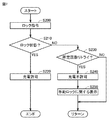
図7は、変形例に係る、外部充電時にECU100で実行される処理を示すフローチャートである。このフローチャートは、充電コネクタ410とインレット220との接続が検出される毎に実行される。
FIG. 7 is a flowchart showing a process executed by the
図7におけるS200、S210およびS220は、図6におけるS100、S110およびS120と同様であるため繰り返し説明しない。 S200, S210, and S220 in FIG. 7 are the same as S100, S110, and S120 in FIG. 6, and will not be described repeatedly.
ECU100は、S210において、ロック装置50がロック状態に切り替わらずに、アンロック状態であると判定すると(S210においてNO)、ロック指令の送信のリトライを所定回数行なったか否かを判定する(S230)。
When the
ECU100は、ロック指令の送信のリトライを所定回数行なっていないと判定すると(S230においてNO)、処理をリターンに進めて、再度ロック指令の送信を行なう(S200)。このように、ロック指令の送信のリトライを所定回数行なうのは、上述のとおり、ノイズ等によってロック装置50がロック指令を誤認識したために、偶発的にロック状態に切り替わらなかったような場合もあり得るからである。なお、所定回数は、回路特性等から発生が想定されるノイズの頻度や大きさ等を考慮して任意に設定される。
When the
ECU100は、S230において、ロック指令の送信のリトライを所定回数行なったと判定すると、外部充電を不許可とする(S240)。ロック指令の送信のリトライを所定回数行なってもロック状態が検出されないということは、ロック装置50の故障等が考えられるためである。
When the
そして、ECU100は、手動操作部材90の操作による手動ロックが可能な旨、および、手動操作部材90の操作による手動ロックの方法を表示装置70に送信し、表示させる(S250)。
Then, the
以上のように、ECU100は、ロック指令によってロック装置50がロック状態に切り替わらなかった場合、再度ロック指令を送信して、ロック装置50がロック状態に切り替わったかを判定する(再指令処理)。そして、ECU100は、再指令処理を所定回数行なう。
As described above, when the
これによって、偶発的状況によりロック装置50がロック状態に切り替わらなかったような場合に、再指令処理によってロック状態に切り替えることができる可能性が高まる。同時に、ユーザに手動操作を行なわせることなく、ロック状態に切り替えることができるので、ユーザの利便性を高めることもできる。
This increases the possibility that the
ECU100は、所定回数の再指令処理によってもロック装置50がロック状態に切り替わらなかった場合に、手動操作部材90の操作による手動ロックに関する情報を表示装置70に表示させる。そして、再指令処理または手動操作部材90の操作による手動ロックによってロック装置50がロック状態に切り替えられると、ECU100は外部充電を許可する。
When the
<その他の変形例>
実施の形態においては、ロック検出スイッチR3を用いて、ロック装置50のロック状態およびアンロック状態を判定したが、ロック装置のロック状態およびアンロック状態を判定できればよい。たとえば、コネクタロックピン52がロック位置に移動した際(ロック状態)に、リンク411と接触する側のコネクタロックピン52の先端に押圧センサを設けてもよい。この場合、コネクタロックピン52がロック位置に移動すると、押圧センサがリンク411に押圧されて、ECU100に信号を送信する。ECU100は、当該信号を検出すると、ロック装置50がロック状態であると判定する。コネクタロックピン52がアンロック位置に移動すると(アンロック状態)、押圧センサは押圧されず、ECU100に信号は送信されない。ECU100は、当該信号を検出しないと、ロック装置50がアンロック状態であると判定する。
<Other variants>
In the embodiment, the lock detection switch R3 is used to determine the locked state and the unlocked state of the
また、ロック装置50のロック状態およびアンロック状態の判定は、コネクタロックピン52の動作位置によって判定されてもよい。ECU100は、コネクタロックピン52の位置がロック位置にあればロック状態と判定し、アンロック位置にあればアンロック状態と判定する。たとえば、ECU100は、ロック指令を送信した後に、コネクタロックピン52がロック位置に移動しているか否かを判定する。
Further, the lock state and the unlock state of the
また、実施の形態においては、車両1が外部の電源から充電ケーブルを介して交流電力の供給を受けて車両1の充電を行なうAC充電の例について説明したが、車両1が外部の電源から充電ケーブルを介して直流電力の供給を受けて車両1の充電を行なうDC充電であっても本開示は適用可能である。 Further, in the embodiment, an example of AC charging in which the vehicle 1 receives AC power from an external power source via a charging cable to charge the vehicle 1 has been described, but the vehicle 1 is charged from an external power source. The present disclosure is also applicable to DC charging in which the vehicle 1 is charged by receiving DC power supplied via a cable.
また、実施の形態においては、手動操作部材90の操作による手動ロックが可能な旨、および、手動操作部材90の操作による手動ロックの方法を表示装置70に表示させてユーザに報知する例について説明したが、ユーザに報知できればよい。たとえば、手動操作部材90の操作による手動ロックが可能な旨、および、手動操作部材90の操作による手動ロックの方法を、ナビゲーション装置や別途設ける音声装置などを用いて音声によって報知してもよい。
Further, in the embodiment, an example will be described in which the manual lock is possible by the operation of the
今回開示された実施の形態は、すべての点で例示であって制限的なものではないと考えられるべきである。本開示の範囲は、上記した実施の形態の説明ではなくて特許請求の範囲によって示され、特許請求の範囲と均等の意味および範囲内でのすべての変更が含まれることが意図される。 The embodiments disclosed this time should be considered to be exemplary and not restrictive in all respects. The scope of the present disclosure is set forth by the claims rather than the description of the embodiments described above, and is intended to include all modifications within the meaning and scope of the claims.
1 車両、2 リッド、10 蓄電装置、15 インナーパネル、18 電源、20 駆動回路、40 電力変換装置、50 ロック装置、51 アクチュエータ、52 コネクタロックピン、70 表示装置、80 コネクタロック装置、90 手動操作部材、100 ECU、220 インレット、221 突起、400 充電ケーブル、410 充電コネクタ、411 リンク、412 軸、413 接続部、414 バネ、415 ボタン、440 交流電力線、L1 第1電線、L2 第2電線、LB 電源線、R1 ロックリレー、R2 アンロックリレー、R3 ロック検出スイッチ、S1,S2,S3 信号線。 1 vehicle, 2 lids, 10 power storage devices, 15 inner panels, 18 power supplies, 20 drive circuits, 40 power converters, 50 lock devices, 51 actuators, 52 connector lock pins, 70 display devices, 80 connector lock devices, 90 manual operation Parts, 100 ECU, 220 inlet, 221 protrusions, 400 charging cable, 410 charging connector, 411 links, 412 axes, 413 connections, 414 springs, 415 buttons, 440 AC power lines, L1 1st wire, L2 2nd wire, LB Power line, R1 lock relay, R2 unlock relay, R3 lock detection switch, S1, S2, S3 signal line.
Claims (4)
前記充電ケーブルの先端に設けられた充電コネクタと接続可能に構成されたインレットと、
前記充電コネクタを前記インレットから取り外し不能なロック状態と、前記充電コネクタを前記インレットから取り外し可能なアンロック状態との切り替えが可能なロック装置と、
前記ロック状態を検出する検出装置と、
前記蓄電装置の充電を制御する制御装置とを備え、
前記ロック装置は、前記アンロック状態から前記ロック状態への切り替えを指示するロック指令を前記制御装置から受けることによって、または、ユーザによる手動操作によって、前記アンロック状態を前記ロック状態に切り替え可能に構成され、
前記制御装置は、前記ロック装置に前記ロック指令を送信した後において、前記ロック状態が検出された場合は前記蓄電装置の充電を許可し、前記ロック状態が検出されなかった場合は前記蓄電装置の充電を不許可とし、
情報を報知する報知装置をさらに備え、
前記制御装置は、前記ロック指令を送信した後に前記蓄電装置の充電を不許可とした場合において、前記手動操作のための部材の設置場所および前記手動操作の方法のうち少なくとも1つを含む情報を前記報知装置に報知させる、車両の充電システム。 It is a vehicle charging system that can charge an in-vehicle power storage device using the electric power supplied from the charging cable outside the vehicle.
An inlet configured to be connectable to a charging connector provided at the tip of the charging cable,
A locking device capable of switching between a locked state in which the charging connector cannot be removed from the inlet and an unlocked state in which the charging connector can be removed from the inlet.
The detection device that detects the locked state and
A control device for controlling the charging of the power storage device is provided.
The locking device can switch the unlocked state to the locked state by receiving a lock command instructing the switching from the unlocked state to the locked state from the control device or by a manual operation by the user. Configured,
After transmitting the lock command to the lock device, the control device permits charging of the power storage device when the lock state is detected, and when the lock state is not detected, the power storage device of the power storage device. Disallowing charging ,
Equipped with a notification device to notify information
When the charging of the power storage device is disallowed after the lock command is transmitted, the control device provides information including at least one of the installation location of the member for the manual operation and the method of the manual operation. A vehicle charging system that notifies the notification device.
Priority Applications (3)
| Application Number | Priority Date | Filing Date | Title |
|---|---|---|---|
| JP2017246677A JP6981237B2 (en) | 2017-12-22 | 2017-12-22 | Vehicle charging system |
| US16/225,955 US10707623B2 (en) | 2017-12-22 | 2018-12-19 | Charging system for vehicle |
| CN201811562589.9A CN109955733A (en) | 2017-12-22 | 2018-12-20 | charging system for vehicles |
Applications Claiming Priority (1)
| Application Number | Priority Date | Filing Date | Title |
|---|---|---|---|
| JP2017246677A JP6981237B2 (en) | 2017-12-22 | 2017-12-22 | Vehicle charging system |
Publications (2)
| Publication Number | Publication Date |
|---|---|
| JP2019115163A JP2019115163A (en) | 2019-07-11 |
| JP6981237B2 true JP6981237B2 (en) | 2021-12-15 |
Family
ID=66951537
Family Applications (1)
| Application Number | Title | Priority Date | Filing Date |
|---|---|---|---|
| JP2017246677A Active JP6981237B2 (en) | 2017-12-22 | 2017-12-22 | Vehicle charging system |
Country Status (3)
| Country | Link |
|---|---|
| US (1) | US10707623B2 (en) |
| JP (1) | JP6981237B2 (en) |
| CN (1) | CN109955733A (en) |
Families Citing this family (12)
| Publication number | Priority date | Publication date | Assignee | Title |
|---|---|---|---|---|
| KR102635922B1 (en) * | 2018-10-10 | 2024-02-13 | 현대자동차주식회사 | Connecter and decking structure between vehicle body and battery comprising the same |
| US11230326B2 (en) * | 2018-11-13 | 2022-01-25 | Rivian Ip Holdings, Llc | Vehicle accessory port and plug |
| WO2020123337A1 (en) * | 2018-12-11 | 2020-06-18 | Metro Mobility, Llc | Electric vehicle fastening and charging system with wireless control |
| JP6705521B1 (en) * | 2019-02-25 | 2020-06-03 | スズキ株式会社 | Electric vehicle |
| JP7226282B2 (en) * | 2019-12-04 | 2023-02-21 | トヨタ自動車株式会社 | CHARGING SYSTEM, VEHICLE, CHARGING METHOD, AND CONTROL DEVICE |
| EP3858658B1 (en) * | 2020-01-31 | 2023-08-16 | Jabil Inc. | Electromechanical actuator having a safety unlocking mechanism |
| JP7234960B2 (en) * | 2020-02-07 | 2023-03-08 | トヨタ自動車株式会社 | ELECTRIC VEHICLE AND CONTROL METHOD OF ELECTRIC VEHICLE |
| DE102020132024A1 (en) * | 2020-12-02 | 2022-06-02 | Kiekert Aktiengesellschaft | Charging device for a motor vehicle |
| CN112428841A (en) * | 2020-12-04 | 2021-03-02 | 安徽江淮汽车集团股份有限公司 | Vehicle-mounted charging system and method |
| CN112677816B (en) * | 2021-01-04 | 2022-11-15 | 东风汽车股份有限公司 | Electric automobile alternating-current charging and discharging method for improving user experience |
| DE102022116326A1 (en) * | 2022-06-30 | 2024-01-04 | Kiekert Aktiengesellschaft | Locking device for a charging plug |
| JP7700755B2 (en) * | 2022-08-30 | 2025-07-01 | トヨタ自動車株式会社 | POWER MANAGEMENT SYSTEM AND POWER MANAGEMENT METHOD |
Family Cites Families (23)
| Publication number | Priority date | Publication date | Assignee | Title |
|---|---|---|---|---|
| US5627448A (en) * | 1993-04-22 | 1997-05-06 | Sumitomo Wiring Systems, Ltd. | Electric vehicle charging connector assembly |
| JP2004331020A (en) * | 2003-05-12 | 2004-11-25 | Calsonic Kansei Corp | Steering lock device |
| JP4893280B2 (en) * | 2006-12-06 | 2012-03-07 | マツダ株式会社 | Notification device for vehicles with automatic transmission |
| JP5124853B2 (en) * | 2008-02-27 | 2013-01-23 | 本田技研工業株式会社 | Electric handle lock device for vehicle |
| JP5231381B2 (en) * | 2009-11-17 | 2013-07-10 | 株式会社東海理化電機製作所 | Connector lock structure for battery charging power receiving connector |
| JP5513153B2 (en) * | 2010-02-12 | 2014-06-04 | 株式会社東海理化電機製作所 | Connector lock structure for battery charging power receiving connector |
| WO2011120719A1 (en) * | 2010-03-31 | 2011-10-06 | Kiekert Ag | Actuator for a motor vehicle and locking device and method |
| JP5486398B2 (en) * | 2010-05-12 | 2014-05-07 | 株式会社東海理化電機製作所 | Power supply plug lock device |
| JP5443270B2 (en) * | 2010-05-27 | 2014-03-19 | 株式会社東海理化電機製作所 | Plug lock device |
| JP5491328B2 (en) * | 2010-09-01 | 2014-05-14 | 株式会社東海理化電機製作所 | Plug lock structure |
| JP2012080646A (en) * | 2010-09-30 | 2012-04-19 | Tokai Rika Co Ltd | Power feeding plug locking device |
| JP2012130127A (en) * | 2010-12-14 | 2012-07-05 | Takaoka Electric Mfg Co Ltd | Charging device for electric moving body |
| JP5635437B2 (en) * | 2011-03-18 | 2014-12-03 | 株式会社東海理化電機製作所 | Power supply plug lock device |
| EP2705975A1 (en) * | 2011-10-25 | 2014-03-12 | Sumitomo Wiring Systems, Ltd. | Vehicle charging device |
| EP2871723B1 (en) * | 2012-07-05 | 2018-04-25 | Nissan Motor Co., Ltd | Charging port device for electric vehicle |
| JP2014239617A (en) * | 2013-06-10 | 2014-12-18 | 日産自動車株式会社 | External charger connection structure for vehicle |
| JP5958432B2 (en) * | 2013-07-23 | 2016-08-02 | トヨタ自動車株式会社 | vehicle |
| EP2842793B1 (en) * | 2013-09-02 | 2021-03-03 | Volvo Car Corporation | Method for controlling charging of a hybrid or electric vehicle |
| JP6418385B2 (en) | 2014-10-22 | 2018-11-07 | 三菱自動車工業株式会社 | Charging connector lock device |
| WO2017141329A1 (en) * | 2016-02-15 | 2017-08-24 | 三菱電機株式会社 | Protocol conversion apparatus |
| KR101734762B1 (en) * | 2016-04-19 | 2017-05-11 | 현대자동차주식회사 | Charging system for vehicle and controlling method thereof |
| CN106585417A (en) * | 2017-01-04 | 2017-04-26 | 重庆长安汽车股份有限公司 | Electric automobile charging port electronic lock control method and system |
| KR102322857B1 (en) * | 2017-04-28 | 2021-11-08 | 현대자동차주식회사 | Method for determining failure in charging connector locking system |
-
2017
- 2017-12-22 JP JP2017246677A patent/JP6981237B2/en active Active
-
2018
- 2018-12-19 US US16/225,955 patent/US10707623B2/en not_active Expired - Fee Related
- 2018-12-20 CN CN201811562589.9A patent/CN109955733A/en active Pending
Also Published As
| Publication number | Publication date |
|---|---|
| US20190199037A1 (en) | 2019-06-27 |
| US10707623B2 (en) | 2020-07-07 |
| JP2019115163A (en) | 2019-07-11 |
| CN109955733A (en) | 2019-07-02 |
Similar Documents
| Publication | Publication Date | Title |
|---|---|---|
| JP6981237B2 (en) | Vehicle charging system | |
| JP5958432B2 (en) | vehicle | |
| CN105083041B (en) | The control of the locking system of electrical charging interface | |
| JP6309886B2 (en) | Vehicle and charging system | |
| JP6819515B2 (en) | vehicle | |
| JP6772872B2 (en) | vehicle | |
| EP2980940A1 (en) | Charging cable locking device and controller | |
| CN112644302A (en) | Vehicle with a steering wheel | |
| KR20150000471A (en) | Vehicle access system and controller therefor | |
| JP5994930B2 (en) | vehicle | |
| JP7047746B2 (en) | Vehicle control unit | |
| CN112895929B (en) | Vehicle and lock control system | |
| CN113928423B (en) | Vehicle with a vehicle body having a vehicle body support | |
| KR20190027556A (en) | Locking apparatus for charging port and controlling method of the same | |
| JP7024513B2 (en) | Electric vehicle | |
| JP5728347B2 (en) | Charging system and charger | |
| JP7816220B2 (en) | electric car | |
| US20230331080A1 (en) | Opening device for a motor vehicle door element | |
| US20230264587A1 (en) | Charging control system | |
| JP7484772B2 (en) | Lid System | |
| JP7768206B2 (en) | Mobile body, control device, and connector lock control method | |
| JP2017135942A (en) | vehicle | |
| JP2021138212A (en) | vehicle |
Legal Events
| Date | Code | Title | Description |
|---|---|---|---|
| A621 | Written request for application examination |
Free format text: JAPANESE INTERMEDIATE CODE: A621 Effective date: 20200728 |
|
| A977 | Report on retrieval |
Free format text: JAPANESE INTERMEDIATE CODE: A971007 Effective date: 20210528 |
|
| A131 | Notification of reasons for refusal |
Free format text: JAPANESE INTERMEDIATE CODE: A131 Effective date: 20210608 |
|
| A521 | Written amendment |
Free format text: JAPANESE INTERMEDIATE CODE: A523 Effective date: 20210726 |
|
| TRDD | Decision of grant or rejection written | ||
| A01 | Written decision to grant a patent or to grant a registration (utility model) |
Free format text: JAPANESE INTERMEDIATE CODE: A01 Effective date: 20211019 |
|
| A61 | First payment of annual fees (during grant procedure) |
Free format text: JAPANESE INTERMEDIATE CODE: A61 Effective date: 20211101 |
|
| R151 | Written notification of patent or utility model registration |
Ref document number: 6981237 Country of ref document: JP Free format text: JAPANESE INTERMEDIATE CODE: R151 |