JP6981021B2 - Electric guitar body and electric guitar - Google Patents
Electric guitar body and electric guitar Download PDFInfo
- Publication number
- JP6981021B2 JP6981021B2 JP2017050528A JP2017050528A JP6981021B2 JP 6981021 B2 JP6981021 B2 JP 6981021B2 JP 2017050528 A JP2017050528 A JP 2017050528A JP 2017050528 A JP2017050528 A JP 2017050528A JP 6981021 B2 JP6981021 B2 JP 6981021B2
- Authority
- JP
- Japan
- Prior art keywords
- rigidity
- vibration
- electric guitar
- counterbore
- convex
- Prior art date
- Legal status (The legal status is an assumption and is not a legal conclusion. Google has not performed a legal analysis and makes no representation as to the accuracy of the status listed.)
- Active
Links
Images


Classifications
-
- G—PHYSICS
- G10—MUSICAL INSTRUMENTS; ACOUSTICS
- G10D—STRINGED MUSICAL INSTRUMENTS; WIND MUSICAL INSTRUMENTS; ACCORDIONS OR CONCERTINAS; PERCUSSION MUSICAL INSTRUMENTS; AEOLIAN HARPS; SINGING-FLAME MUSICAL INSTRUMENTS; MUSICAL INSTRUMENTS NOT OTHERWISE PROVIDED FOR
- G10D1/00—General design of stringed musical instruments
- G10D1/04—Plucked or strummed string instruments, e.g. harps or lyres
- G10D1/05—Plucked or strummed string instruments, e.g. harps or lyres with fret boards or fingerboards
- G10D1/08—Guitars
- G10D1/085—Mechanical design of electric guitars
-
- G—PHYSICS
- G10—MUSICAL INSTRUMENTS; ACOUSTICS
- G10D—STRINGED MUSICAL INSTRUMENTS; WIND MUSICAL INSTRUMENTS; ACCORDIONS OR CONCERTINAS; PERCUSSION MUSICAL INSTRUMENTS; AEOLIAN HARPS; SINGING-FLAME MUSICAL INSTRUMENTS; MUSICAL INSTRUMENTS NOT OTHERWISE PROVIDED FOR
- G10D3/00—Details of, or accessories for, stringed musical instruments, e.g. slide-bars
- G10D3/02—Resonating means, horns or diaphragms
-
- G—PHYSICS
- G10—MUSICAL INSTRUMENTS; ACOUSTICS
- G10H—ELECTROPHONIC MUSICAL INSTRUMENTS; INSTRUMENTS IN WHICH THE TONES ARE GENERATED BY ELECTROMECHANICAL MEANS OR ELECTRONIC GENERATORS, OR IN WHICH THE TONES ARE SYNTHESISED FROM A DATA STORE
- G10H3/00—Instruments in which the tones are generated by electromechanical means
- G10H3/12—Instruments in which the tones are generated by electromechanical means using mechanical resonant generators, e.g. strings or percussive instruments, the tones of which are picked up by electromechanical transducers, the electrical signals being further manipulated or amplified and subsequently converted to sound by a loudspeaker or equivalent instrument
- G10H3/14—Instruments in which the tones are generated by electromechanical means using mechanical resonant generators, e.g. strings or percussive instruments, the tones of which are picked up by electromechanical transducers, the electrical signals being further manipulated or amplified and subsequently converted to sound by a loudspeaker or equivalent instrument using mechanically actuated vibrators with pick-up means
- G10H3/18—Instruments in which the tones are generated by electromechanical means using mechanical resonant generators, e.g. strings or percussive instruments, the tones of which are picked up by electromechanical transducers, the electrical signals being further manipulated or amplified and subsequently converted to sound by a loudspeaker or equivalent instrument using mechanically actuated vibrators with pick-up means using a string, e.g. electric guitar
- G10H3/181—Details of pick-up assemblies
Description
本発明は、弦の振動特性を改善することができるエレクトリックギターのボディ、および同ボディを備えるエレクトリックギターに関する。 The present invention relates to an electric guitar body capable of improving the vibration characteristics of strings, and an electric guitar provided with the body.
エレクトリックギターでは、電磁ピックアップにより、弦の振動を電磁誘導により電気信号に変換する。変換された電気信号はアンプにより増幅されてスピーカーから音として出力される。 In an electric guitar, an electromagnetic pickup converts the vibration of a string into an electric signal by electromagnetic induction. The converted electric signal is amplified by an amplifier and output as sound from a speaker.
エレクトリックギターの弦の振動は、エレクトリックギターのボディやネックにも伝達される。ボディやネックを振動させるために弦の振動エネルギーは消費されて、弦の振動は減衰する。このように、ボディやネックは、弦の振動やエレクトリックギターの音質に影響を与える。 The vibration of the strings of the electric guitar is also transmitted to the body and neck of the electric guitar. The vibration energy of the strings is consumed to vibrate the body and neck, and the vibration of the strings is attenuated. In this way, the body and neck affect the vibration of the strings and the sound quality of the electric guitar.
エレクトリックギターのボディには、内部に空洞の無いリッドボディが多く用いられている。ソリッドボディであるエレクトリックギターのボディには、ネックを接合する部分(以降、「ネックポケット」と称す)や、電装品を格納するための電装座繰りなどの凹部が形成される。また、エレクトリックギターを弾きやすくするためにボディの一部を削り取るカッタウェイ処理が施され、削り取られずに残った部分が凸部としてボディに形成されることが多い。そのため、エレクトリックギターのボディには凹凸部が多く形成される。 The body of an electric guitar is often a lid body with no internal cavities. The body of an electric guitar, which is a solid body, is formed with a portion for joining a neck (hereinafter referred to as a "neck pocket") and a recess such as an electrical counterbore for storing electrical components. In addition, a cutaway process is applied to scrape off a part of the body to make it easier to play the electric guitar, and the remaining part that is not scraped off is often formed on the body as a convex portion. Therefore, many uneven portions are formed on the body of the electric guitar.
エレクトリックギターのボディに伝達された振動が、ボディ全体にバランスよく伝達されると、ボディに豊かな振動を生み出すことができ、弦やブリッジ(弦をボディに取り付ける部分)にその振動をフィードバックすることができる。 When the vibration transmitted to the body of the electric guitar is transmitted to the entire body in a well-balanced manner, it is possible to generate rich vibration in the body and feed it back to the strings and bridge (the part where the strings are attached to the body). Can be done.
エレクトリックギターのボディには、ボディの構造(形状、材質等)が持つ振動的な特性である振動モードが励起する。振動モードに対応する固有振動数で振動した場合のボディの変形形状を示す「モード形状」のバランスを解析することにより、ボディ全体にバランスよい振動が発生するかを調査することができる。例えば、振動の変位が大きい箇所がボディの一部に偏っている場合、振動のバランスがよいとはいえない。 The body of an electric guitar is excited by a vibration mode, which is a vibrational characteristic of the body structure (shape, material, etc.). By analyzing the balance of the "mode shape" that indicates the deformed shape of the body when vibrating at the natural frequency corresponding to the vibration mode, it is possible to investigate whether a well-balanced vibration is generated in the entire body. For example, if the portion where the displacement of vibration is large is biased to a part of the body, it cannot be said that the vibration balance is good.
エレクトリックギターのボディにおいては、上記凹凸部によって局所的に剛性が低くなる箇所が現われる。ボディのうち剛性が低い箇所は他の箇所よりも振動の影響を受けやすいため、振動の変位が大きくなりやすい。その結果、ボディ全体のモード形状のバランス(振動のバランス)が悪化する。この場合、弦の振動が早く減衰したり、弦の振動の振幅が弦を弾いた後すぐに大きくならなかったりする。 In the body of an electric guitar, a part where the rigidity is locally lowered appears due to the uneven portion. Since the part of the body with low rigidity is more susceptible to vibration than other parts, the displacement of vibration tends to be large. As a result, the balance of the mode shape (balance of vibration) of the entire body deteriorates. In this case, the vibration of the string may be attenuated quickly, or the amplitude of the vibration of the string may not increase immediately after the string is played.
また、その振動モードにおける固有振動数の定在波の節となる位置にブリッジやネックポケットが配されると、弦の振動がボディに伝達されにくい。その結果、ボディに豊かな振動を生み出して、その振動を弦にフィードバックすることができない。
特許文献1には、ボディに金属板を固定し、音質を改善したエレクトリックギターが記載されている。しかしながら、特許文献1に記載の金属板は、ボディに発生する振動に影響を与えることが目的であったが、ボディに発生するモード形状のバランス(振動のバランス)を調整することが目的ではなかった。
Further, if a bridge or a neck pocket is arranged at a position that becomes a node of a standing wave of a natural frequency in the vibration mode, it is difficult for the vibration of the string to be transmitted to the body. As a result, rich vibrations cannot be generated in the body and the vibrations cannot be fed back to the strings.
Patent Document 1 describes an electric guitar in which a metal plate is fixed to a body to improve sound quality. However, although the metal plate described in Patent Document 1 is intended to affect the vibration generated in the body, it is not intended to adjust the balance of the mode shape (vibration balance) generated in the body. rice field.
本発明は、上記の事情に鑑みなされたもので、発生するモード形状のバランス(振動のバランス)を調整し、音質を改善することができるエレクトリックギターのボディ、および同ボディを備えるエレクトリックギターを提供することを目的とする。 The present invention has been made in view of the above circumstances, and provides an electric guitar body capable of adjusting the balance of generated mode shapes (vibration balance) and improving sound quality, and an electric guitar having the same body. The purpose is to do.
上記課題を解決するために、この発明は以下の手段を提案している。
本発明に係るエレクトリックギターのボディは、ソリッドボディからなり、凹部が形成されたボディ本体と、前記凹部の内側面のうち、互いに離れて位置する二つ以上の接触領域に接触して前記凹部の剛性を補強する凹部剛性補強材と、を備え、二つの前記接触領域の配列方向が、前記凹部の内側面において互いに対向する二つの領域の間の距離が最も長くなる前記二つの領域の配列方向に直交する方向であり、前記凹部剛性補強材は、二つの前記接触領域に接触し、距離が最も長くなる前記二つの領域に接触していない。
In order to solve the above problems, the present invention proposes the following means.
The body of the electric guitar according to the present invention is made of a solid body, and is in contact with two or more contact regions of the inner surface of the recess and the inner side surface of the recess, which are located apart from each other. The concave rigidity reinforcing material for reinforcing the rigidity is provided , and the arrangement direction of the two regions is such that the distance between the two regions facing each other on the inner surface of the concave portion is the longest. The concave rigidity reinforcing material is in contact with the two contact regions and is not in contact with the two regions having the longest distance .
本発明に係るエレクトリックギターのボディは、ソリッドボディからなり、凸部が形成されたボディ本体と、第一の端部と第二の端部とを有し、前記ボディ本体に取り付けられる凸部剛性補強材とを、備え、前記凸部は、前記ボディ本体の他の部分に対して突出し、前記第一の端部は、前記凸部と前記ボディ本体の他の部分との接続部分に固定されている。 The body of the electric guitar according to the present invention is made of a solid body, has a body body having a convex portion formed therein, and has a first end portion and a second end portion, and the convex portion rigidity attached to the body main body. A reinforcing material is provided, the convex portion protrudes with respect to another portion of the body body, and the first end portion is fixed to a connecting portion between the convex portion and the other portion of the body body. ing.
本発明に係るエレクトリックギターは、上記のいずれかのボディを備える。 The electric guitar according to the present invention includes any of the above bodies.
本発明によれば、エレクトリックギターのボディにおいて、発生するモード形状のバランス(振動のバランス)を調整し、音質を改善することができる。 According to the present invention, in the body of an electric guitar, the balance of the mode shape (vibration balance) generated can be adjusted to improve the sound quality.
以下、本発明に係るエレクトリックギターのボディ、および同ボディを備えたエレクトリックギターの一実施形態を、図1から図3を参照しながら説明する。なお、図面を見やすくするため、各構成要素の厚さや寸法の比率は適宜調整されている。 Hereinafter, an electric guitar body according to the present invention and an embodiment of an electric guitar provided with the same body will be described with reference to FIGS. 1 to 3. In order to make the drawings easier to see, the thickness and dimensional ratio of each component are adjusted as appropriate.
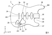
図1は本実施形態に係るエレクトリックギターのボディ1を、ボディ1の板厚方向(Z軸方向)に対して直交する一方の面(表面2a)から見た平面図である。図2は、ボディ1の表面2aの反対面である他方の面(裏面2b)から見た平面図である。図3は、ボディ1を備えるエレクトリックギター10をボディ1の表面2aから見た平面図である。
FIG. 1 is a plan view of the body 1 of the electric guitar according to the present embodiment as viewed from one surface (
図1および図2に示すように、本実施形態に係るボディ1は、ボディ本体2と、電装座繰り用剛性補強材31(凹部剛性補強材)と、凸部剛性補強材32を、備えている。
As shown in FIGS. 1 and 2, the body 1 according to the present embodiment includes a body
図3に示すように、エレクトリックギター10は、ボディ1と、ネック4と、弦5と、を備えている。長尺形状のネック4の基端が、後述するボディ1のネック座繰り23(ネックポケット)に挿入されて、接合されている。弦5は、ネックの長手方向(張弦方向、X軸方向)に沿って張られる。
As shown in FIG. 3, the
ボディ本体2は、内部に空洞の無いソリッドボディからなる。ボディ本体2の材質は、アルダー、メイプル、マホガニー等の木材である。2つ以上の違った木材を組み合わせて使用されることもある。ボディ本体2は、板状に形成されている。
The
図1および図2に示すように、ボディ本体2には、電装座繰り21、電磁ピックアップ座繰り22、ネック座繰り23、ブリッジ座繰り24、ジャック座繰り25などの複数の座繰り(凹部、格納部)が形成されている。ブリッジ座繰り24のみボディ本体2を貫通しており、他の座繰りは、ボディ本体2を貫通していない。
As shown in FIGS. 1 and 2, the body
電装座繰り21は、エレクトリックギター10の電磁ピックアップ61(図3参照)が出力する音響信号のボリュームやトーン等を調整するコントローラなどの電装品を格納するための座繰りである。電装座繰り21は、ボディ本体2の表面2aにおいて、板厚方向(Z軸方向)に開口している。
コントローラには、図3に示すように、三個のボリュームスイッチ62と、有効化する電磁ピックアップ61を切り替えるピックアップセレクター63とが含まれる。
The
As shown in FIG. 3, the controller includes three
電磁ピックアップ座繰り22は、電磁ピックアップ61を格納するための座繰りである。電磁ピックアップ座繰り22は、ボディ本体2の表面2aにおいて、板厚方向(Z軸方向)に開口している。電磁ピックアップ座繰り22には、シングルコイル・ピックアップや、ハムバッキング・ピックアップなどの種類の電磁ピックアップ61を複数格納できる。電磁ピックアップ座繰り22は、張弦方向(X軸方向)に並べて配置される。本実施形態のボディ本体2には、シングルコイル・ピックアップを三個並べて配置できるように電磁ピックアップ座繰り22が形成されている。
The
ネック座繰り23は、ボディ本体2に長尺形状のネック4の基端を格納して接合するための座繰りである。ネック座繰り23は、ボディ本体2の表面2aにおいて、板厚方向(Z軸方向)に開口しているととともに、ボディ本体2の側面において、張弦方向(X軸方向)にも開口している。
ネック座繰り23は、板厚方向(Z軸方向)および張弦方向(X軸方向)に直交するY軸方向において、ボディ本体2の中央部分に形成されている。また、ネック座繰り23は、電磁ピックアップ座繰り22と共に張弦方向(X軸方向)に並べて配置される。
ネック座繰り23にはネック4の基端が挿入される。そのうえで、ネック4はボディ本体2に対してジョイントねじや接着剤等で接合することでボディ本体2に取り付けられる。
The
The
The base end of the neck 4 is inserted into the
ブリッジ座繰り24は、弦5の基端部を固定するブリッジ65(図3参照)を格納するための座繰りである。また、ブリッジ座繰り24は、ネック座繰り23および電磁ピックアップ座繰り22と共に張弦方向(X軸方向)に並べて配置される。
長尺形状のネック4の先端のヘッドには、ペグが設けられており、弦5の先端部を巻き付けることができる。
The
A peg is provided on the head at the tip of the long neck 4, and the tip of the
ジャック座繰り25は、ジャック66(図3参照)を格納するための座繰りである。ジャック座繰り25は、ボディ本体2の表面2aにおいて、板厚方向(Z軸方向)に開口している。
ジャック66にはケーブルが挿入され、ジャック66を経由してケーブルに電磁ピックアップ61の出力である音響信号が出力される。
The
A cable is inserted into the
このように、ボディ本体2に形成される複数の座繰りは、各機能を満たすためにボディ本体2に形成された凹部であって、ボディ本体2に発生する振動を考慮して形成されたものではない。ボディ本体2においては、凹部によって局所的に剛性が低くなる箇所が現われる。ボディ本体2のうち剛性が低い箇所は他の箇所よりも振動の影響を受けやすいため、振動の変位が大きくなりやすい。
As described above, the plurality of counterbore formed in the
また、複数の座繰りは、張弦方向(X軸方向)に見て、弦5を中心とした線対称に形成されていない場合が多い。弦5の振動が、弦5を中心として、Y軸方向に均等に伝達されることで、ボディ本体2にバランスのよい振動が生成されると考えられる。そのため、複数の座繰りが、張弦方向(X軸方向)に見て、弦5を中心とした線対称に形成されていない場合、座繰りが多い側に振動の変位が大きくなる箇所が偏って発生しやすいと考えられる。
Further, the plurality of counterbore are often not formed line-symmetrically with respect to the
ボディ本体2において、弦5よりY軸正方向側の半分(以降「ボディ本体上側」と称す)より、弦5よりY軸負方向側の半分(以降「ボディ本体下側」と称す)に、座繰りが多く形成されている。例えば、電装座繰り21やジャック座繰り25は、ボディ本体下側にのみ形成されている。そのため、ボディ本体下側に振動の変位が大きくなる箇所が偏って発生しやすいと考えられる。その結果、ボディ全体のモード形状のバランス(振動のバランス)が悪化する。
In the
ボディ本体2のボディ本体下側には、ネック4が取り付けられるネック座繰り23付近の一部を削り取ったカッタウェイ部26が形成される。カッタウェイ部26を形成することで、演奏者が弦5の基端側に触れやすくなり、演奏が容易になる。ボディ本体2において、図1および図3に示すように、ネック座繰り23のY軸負方向側に、カッタウェイ部26を形成することで、特に高音域の音の演奏が容易となる。
一方、このカッタウェイ部26を形成することで、削られずに残った部分が凸状の第一突出部27として形成される。
On the lower side of the body body of the
On the other hand, by forming the
エレクトリックギター10を立って演奏するために使用するストラップの両端を固定するストラップピン281、282が、ボディ本体2の二か所に設けられている。図3に示すように、第一ストラップピン281は、ボディ本体2のX軸方向の基端部(ネック座繰り23が形成されるX軸方向の先端部と反対方向の端部)に取り付けられている。第二ストラップピン282(ストラップピン)は、第一突出部27のネック4を挟んだ反対側に形成された第二突出部29(取付部)に取り付けられている。
Strap pins 281 and 282 for fixing both ends of the strap used for standing and playing the
第一ストラップピン281と、第二ストラップピン282とに、ストラップを取り付けたときに、エレクトリックギター10を安定して保持できるように、ストラップピン281、282の取り付け位置が決められている。第二突出部29をボディ本体2に設けることで、第二ストラップピン282をネック4先端側に配置することができ、ストラップによりエレクトリックギター10を安定して保持しやすくなる。
The attachment positions of the strap pins 281 and 282 are determined so that the
このように、第一突出部27と、第二突出部29とは、各機能を満たすためにボディ本体2に形成された凸部であって、ボディ本体2に発生する振動を考慮して形成されたものではない。ボディ本体2においては、凸部によって局所的に剛性が低くなる箇所が現われる。ボディ本体2のうち剛性が低い箇所は他の箇所よりも振動の影響を受けやすいため、振動の変位が大きくなりやすい。
As described above, the first protruding
また、第一突出部27と、第二突出部29とは、張弦方向(X軸方向)に見て、弦5を中心とした線対称に形成されていない場合が多い。第一突出部27よりも突出している第二突出部29の方が、剛性が低くなりやすく、より振動の影響を受けやすい。そのため、第一突出部27と比べて、より突出している第二突出部29の方に、振動の変位が大きくなる箇所が偏って発生しやすいと考えられる。その結果、ボディ全体のモード形状のバランス(振動のバランス)が悪化する。
Further, the first protruding
電装座繰り用剛性補強材31は、電装座繰り21に設けられた剛性を補強する補強材である。電装座繰り用剛性補強材31は、図1に示すように、電装座繰り21の内側面のうち互いに離れて位置する第一接触領域211と、第二接触領域212とに対して、接触して剛性を補強するように両内側面(211、212)間に設けられている。そのため、ボディ1において、電装座繰り21が形成された部位の剛性は高まる。電装座繰り用剛性補強材31は、第一接触領域211と、第二接触領域212とに対して、接触して圧力を加えるように両内側面(211、212)間に設けられていてもよい。
The electrical seating
電装座繰り用剛性補強材31を設けることで、電装座繰り21の形成によって低下したボディ本体2の剛性を補強により高めることができる。
低下していたボディ本体2の剛性を補強により高めることで、電装座繰り21に発生していた大きな振動の変位を低減させることができる。
By providing the
By increasing the reduced rigidity of the
また、座繰りが多く形成されているボディ本体下側に形成された電装座繰り21の剛性を高めることで、ボディ本体上側よりもボディ本体下側に振動の変位が大きくなる箇所が偏っていた振動バランスを改善できる。
その結果、弦5の振動がボディ1にバランスよく伝達され、ボディ1に豊かな振動を生み出すことができ、弦5やブリッジ65にその振動をフィードバックすることができる。
Further, by increasing the rigidity of the
As a result, the vibration of the
電装座繰り用剛性補強材31は、電装座繰り21の内側面において、第一接触領域と第二接触領域との配列方向が、内側面において互いに対向する二つの領域の間の距離が最も長くなる方向と直交する方向(直交方向)となるように設けられることが好ましい。直交方向がボディ本体2において剛性が最も低下しやすい方向であるからである。この直交方向に電装座繰り用剛性補強材31を設けることで、より好適に電装座繰り21形成によって低下したボディ本体2の剛性を補強により高めることができる。
In the electrical seating
また、電装座繰り用剛性補強材31は、電装座繰り21の内側面のうち、二つ以上の領域と接していてもよい。多くの領域と接することで、より好適に電装座繰り21形成によって低下したボディ本体2の剛性を補強により高めることができる。
Further, the
凸部剛性補強材32は、ボディ本体2の裏面2bに取り付けられた第二突出部29の剛性を補強する補強材である。凸部剛性補強材32は、第一の端部321と第二の端部322を有する帯状の板材であり、木材よりも剛性が高い。ここで、第一の端部321と第二の端部322とは、凸部剛性補強材32の長手方向の両端部である。凸部剛性補強材32は、凸部剛性補強材32の板厚方向から見て湾曲している。第二突出部29とボディ本体2の他の部分との接続部分(付根付近)に第一の端部321が固定されており、ボディ1の他の部分に第二の端部322が配置されている。第二突出部29は、凸部剛性補強材32によって剛性が高まる。
ここで、第二突出部29とボディ本体2の他の部分との接続部分は、第二突出部29形成によって局所的に剛性が低くなる箇所である。接続部分は形状が不連続な部分となるため、剛性は低下する。その接続部分に第一の端部321を固定することで、局所的に剛性が低くなった箇所の剛性は高まる。
The convex portion
Here, the connecting portion between the second protruding
凸部剛性補強材32を設けることで、第二突出部29形成によって低下したボディ本体2の剛性を補強により高めることができる。
低下していた剛性を補強により高めることで、第二突出部29に発生していた大きな振動の変位を低減させることができる。
By providing the convex portion
By increasing the reduced rigidity by reinforcement, it is possible to reduce the displacement of the large vibration generated in the
また、第二突出部29の剛性を高めることで、第一突出部27側よりも第二突出部29側に振動の変位が大きくなる箇所が偏っていた振動バランスを改善できる。
その結果、弦5の振動がボディ1にバランスよく伝達され、ボディ1に豊かな振動を生み出すことができ、弦5やブリッジにその振動をフィードバックすることができる。
Further, by increasing the rigidity of the second protruding
As a result, the vibration of the
凸部剛性補強材32の第一の端部321が、第二突出部29の付根部分に近い場所に配置されていれば、第二の端部322は、第二突出部29の近傍から離れたボディ本体2の部位に配置されていればよい。第一の端部321と第二の端部322とができる限り互いに遠く位置するように配置されている方が、第二突出部29の剛性を好適に高めることができる。
例えば、第一の端部321と第二の端部322とが、ボディ本体2の板厚方向と直交する方向(例えば、X軸方向やY軸方向)のボディ本体2の中心軸(例えば、X軸方向のボディ本体中心軸CXやY軸方向のボディ本体中心軸CY)を挟んで反対側に配置されていると、第二突出部29の剛性をより好適に高めることができる。
ここで、凸部剛性補強材32は、アーチ状でなく、長尺状であってもよい。
If the
For example, the
Here, the convex
凸部剛性補強材32は、張弦方向(X軸方向)と垂直な方向にも延びているため、第二突出部29の剛性を補強する機能以外の機能も有する。凸部剛性補強材32は、ボディ1にY軸方向に対する「曲げ」の振動が発生した際に、その「曲げ」の振動に対する剛性を高めることができる。
Since the convex portion
Y軸方向への「曲げ」に対する剛性を高めることで、弦5の振動に特に影響を与える箇所であるブリッジ座繰り24やネック座繰り23が、振動モードにおける固有振動数の定在波の節になることを抑制できる。弦5の振動がボディ1に伝達されやすくなり、また、ボディ1の振動特性が弦の振動に悪影響を与えない。
By increasing the rigidity against "bending" in the Y-axis direction, the
このように構成されたエレクトリックギター10において、演奏者は、電磁ピックアップ付近の弦5を弾くことで弦5に振動を発生させる。ここで弦5には、Z軸方向とY軸方向に上下する振動が発生する。電磁ピックアップは、この振動を電磁誘導により電気信号に変換する。電気信号への変換においては、ボリュームスイッチ62やピックアップセレクター63などの制御を受ける。こうして変換された電気信号がジャック66に挿入されたケーブルから出力される。
In the
以上のように構成される本実施形態のエレクトリックギター10のボディ1は、電装座繰り用剛性補強材31を備えることにより、電装座繰り21形成によって低下したボディ1の剛性を補強により高めることができる。
また、ボディ1が凸部剛性補強材32を備えることにより、第二突出部29の形成によって低下したボディ本体2の剛性を補強により高めることができる。
低下していたボディ本体2の剛性を補強により高めることで、電装座繰り21や第二突出部29に発生していた大きな振動の変位を低減させることができる。
The body 1 of the
Further, since the body 1 is provided with the convex
By increasing the reduced rigidity of the
座繰り(凹部)や突出部(凸部)が、張弦方向(X軸方向)に見て、弦5を中心とした線対称に形成されていない場合であっても、電装座繰り用剛性補強材31や凸部剛性補強材32を備えることで、ボディ1全体のモード形状のバランス(振動のバランス)を改善することができる。
その結果、弦5の振動がボディ1にバランスよく伝達され、ボディ1に豊かな振動を生み出すことができ、弦5やブリッジにその振動をフィードバックすることができる。
Even if the countersunk (concave) or protruding portion (convex) is not formed line-symmetrically with respect to the
As a result, the vibration of the
また、凸部剛性補強材32は、張弦方向(X軸方向)と垂直な方向にも延びるように設けることで、Y軸方向への「曲げ」に対する剛性を高めることができる。これにより、ブリッジ座繰り24やネック座繰り23が、振動モードにおける固有振動数の定在波の節になることを抑制できる。
Further, by providing the convex
これらの効果により、ボディ1を備えたエレクトリックギター10は、弦5の振動特性を改善して音質を改善することができる。
Due to these effects, the
(変形例)
以上、本発明の一実施形態について図面を参照して詳述したが、具体的な構成はこの実施形態に限られるものではなく、本発明の要旨を逸脱しない範囲の設計変更等も含まれる。また、上述の一実施形態および変形例において示した構成要素は適宜に組み合わせて構成することが可能である。
(Modification example)
Although one embodiment of the present invention has been described in detail with reference to the drawings, the specific configuration is not limited to this embodiment, and includes design changes and the like within a range that does not deviate from the gist of the present invention. In addition, the components shown in the above-described embodiment and modification can be appropriately combined and configured.
本発明の一実施形態として、エレクトリックギター10を用いて説明を行ったが、本発明は、ソリッドボディを備える楽器、例えばエレクトリックベースギターにも同様の効果を発揮することができる。
Although the
ボディ1は、電装座繰り用剛性補強材31と凸部剛性補強材32のいずれか一つのみを備えていてもよい。また、電装座繰り21以外の座繰りに電装座繰り用剛性補強材31と同等の補強材を設けてもよい。座繰りの形成によって低下したボディ本体2の剛性を高めることができる。
The body 1 may include only one of the electrical seating
ボディ本体の形状は、一実施形態で示したような一般的なエレクトリックギター10のボディ1の形状に限られない。V字型のボディ形状のように凸部をさらに有するボディ形状であってもよい。このようなボディであっても、凸部剛性補強材32を設けることで、上記実施形態と同様の効果を発揮することができる。
The shape of the body body is not limited to the shape of the body 1 of the general
ボディ本体2と、ネック4は一体成形されていてもよい。ボディ本体2に、電装座繰り用剛性補強材31もしくは凸部剛性補強材32を設けることで、このような構成であっても、上記実施形態と同様の効果を発揮できる。
The
座繰りの内側面が、ボディ本体2の板厚方向(Z軸方向)に平行でなく、斜めになるように形成されていてもよい。電装座繰り用剛性補強材31は、斜めに形成された内側面に対して剛性を補強するように設けられていればよい。
The inner side surface of the counterbore may be formed so as to be slanted rather than parallel to the plate thickness direction (Z-axis direction) of the
凸部剛性補強材32は、ボディ本体2の裏面2bに取り付けられているが、取り付け位置はこれに限られない。例えば、ボディ本体2の木材の内部に凸部剛性補強材32を取り付けてもよい。例えば、複数の木材を重ね合わせてボディ本体2を形成する場合、第二突出部29の剛性を補強するために、木材の間に木材より剛性が高い凸部剛性補強材32を挟み込んでもよい。
この場合には、凸部剛性補強材32が外部に露出しないため、凸部剛性補強材32の取り付けによるエレクトリックギターの外観意匠の低下を防ぐことができる。
The convex
In this case, since the convex
また、凸部剛性補強材32は、ボディ本体2の裏面2bから側面や表面2aまで延びていてもよい。さらに、表面2aから裏面2bまで沿って延び、第二突出部29の付根部分を囲むように設けられていてもよい。より好適に第二突出部29の剛性を高めることができる。
Further, the convex
凸部剛性補強材32とは別に、第一の端部と第二の端部とを有する曲げ剛性補強材を設けてもよい。曲げ剛性補強材が張弦方向(X軸方向)とほぼ直交する方向に延びるように曲げ剛性補強材の第一の端部と第二の端部をY軸方向に並べて配列する。曲げ部用剛性補強材は、ボディ1にY軸方向に対する「曲げ」の振動が発生した際に、その「曲げ」の振動に対する剛性を高めることができる。
また、Y軸方向への「曲げ」に対する剛性を高めることで、弦5の振動に特に影響を与える箇所であるブリッジ座繰り24やネック座繰り23が、振動モードにおける固有振動数の定在波の節になることを抑制できる。弦5の振動がボディ1に伝達されやすくなり、また、ボディ1の振動特性が弦の振動に悪影響を与えない。
In addition to the convex
Further, by increasing the rigidity against "bending" in the Y-axis direction, the
次に、エレクトリックギター10のボディ1に発生する「モード形状」のバランスをシミュレーションによって解析した結果について図4から図6を参照して説明する。
Next, the results of analyzing the balance of the "mode shape" generated in the body 1 of the
(1−1 シミュレーション設定)
ボディ本体2への電装座繰り用剛性補強材31の取り付けの有無による、モード形状のバランスの変化を、シミュレーションによって解析した結果を図4に示す。ここで、凸部剛性補強材32は、ボディ本体2に取り付けていない。
(1-1 Simulation settings)
FIG. 4 shows the result of analysis by simulation of the change in the balance of the mode shape depending on the presence or absence of the
(1−2 シミュレーション結果)
図4にシミュレーションによって解析した結果を示す。図4は、ボディ本体2に発生するモード形状のうち、「ねじれ」が発生しているモード形状を示している。図4では、グレースケールにおいて、白い部分がより振動の変位が大きく、黒い部分がより振動の変位が小さいことを示している。
図4(a)は、ボディ本体2に電装座繰り用剛性補強材31を取り付けていない場合のモード形状を示している。図4(b)は、ボディ本体2に電装座繰り用剛性補強材31を取り付けている場合のモード形状を示している。
(1-2 Simulation result)
FIG. 4 shows the results of analysis by simulation. FIG. 4 shows a mode shape in which "twisting" occurs among the mode shapes generated in the body
FIG. 4A shows a mode shape when the rigid reinforcing
図4(a)に示すように、ボディ本体2に電装座繰り用剛性補強材31を取り付けていない場合、ボディ本体2のうち電装座繰り21が形成された部位における振動の変位が大きい。
図4(b)に示すように、ボディ本体2に電装座繰り用剛性補強材31を取り付けた場合、電装座繰り21が形成された部位における振動の変位が小さくなっている。電装座繰り21が形成された部位に発生していた大きな振動の変位を低減させることができている。
As shown in FIG. 4A, when the
As shown in FIG. 4 (b), when the rigid reinforcing
また、ボディ本体2のモード形状のバランス(振動のバランス)が改善している。図4(b)のモード形状の方が、張弦方向(X軸方向)に見て、弦5を中心とした線対称により近い形状となっている。
また、電装座繰り用剛性補強材31を取り付けることで、第二突出部29の先端部がより大きく振動するようになっている。
電装座繰り用剛性補強材31を取り付けることにより、ボディ本体2に均等に振動が伝達されるようになったと考察される。
Further, the balance of the mode shape (balance of vibration) of the
Further, by attaching the electrical seating
It is considered that the vibration is evenly transmitted to the
(2−1 シミュレーション設定)
次に、ボディ本体2への凸部剛性補強材32の取り付けの有無による、モード形状のバランスの変化を、シミュレーションによって解析した結果を図5および図6に示す。ここで、電装座繰り用剛性補強材31は、ボディ本体2に取り付けていない。
(2-1 Simulation setting)
Next, FIGS. 5 and 6 show the results of simulation analysis of changes in the balance of the mode shape depending on whether or not the convex
(2−2 シミュレーション結果)
図5にシミュレーションによって解析した結果を示す。図5は、ボディ本体2の表面2aに発生するモード形状のうち、「ねじれ」が発生しているモード形状を示している。
図5(a)は、ボディ本体2に凸部剛性補強材32を取り付けていない場合のモード形状を示している。図5(b)は、ボディ本体2に凸部剛性補強材32を取り付けている場合のモード形状を示している。
(2-2 simulation result)
FIG. 5 shows the results of analysis by simulation. FIG. 5 shows a mode shape in which "twist" is generated among the mode shapes generated on the
FIG. 5A shows a mode shape when the convex
図5(a)に示すように、ボディ本体2に凸部剛性補強材32を取り付けていない場合、第一突出部27と比べて、より突出している第二突出部29の方が、その先端部において、振動の変位が大きい。
図5(b)に示すように、ボディ本体2に凸部剛性補強材32を取り付けた場合、第二突出部29の先端部の振動の変位が小さくなっている。さらに、第一突出部27の先端部の振動の変位が大きくなっている。第二突出部29に発生していた大きな振動の変位を低減させることができている。
As shown in FIG. 5A, when the convex
As shown in FIG. 5B, when the convex
また、ボディ本体2のモード形状のバランス(振動のバランス)が改善している。図5(b)のモード形状の方が、張弦方向(X軸方向)に見て、弦5を中心とした線対称により近い形状となっている。ボディ本体2に均等に振動が伝達されるようになったと考察される。
Further, the balance of the mode shape (balance of vibration) of the
(2−3 シミュレーション結果)
図6は、ボディ本体2の表面2aに発生するモード形状のうち、Y軸方向に「曲げ」が発生しているモード形状を示している。
図6(a)は、ボディ本体2に凸部剛性補強材32を取り付けていない場合のモード形状を示している。図6(b)は、ボディ本体2に凸部剛性補強材32を取り付けている場合のモード形状を示している。
(2-3 simulation result)
FIG. 6 shows a mode shape in which "bending" occurs in the Y-axis direction among the mode shapes generated on the
FIG. 6A shows a mode shape when the convex
ボディ本体2のモード形状のバランス(振動のバランス)が改善している。図6(b)のモード形状の方が、張弦方向(X軸方向)に見て、弦5を中心とした線対称により近い形状となっている。ボディ本体2に均等に振動が伝達されるようになったと考察される。
The balance of the mode shape (balance of vibration) of the
また、図6において、Y軸方向に延びる濃いグレーで示される帯状の2本線が、本振動モードにおける固有振動数の定在波の節に相当する部分である。
図6(a)に示すように、ボディ本体2に凸部剛性補強材32を取り付けていない場合、定在波の節に相当する部分が、電磁ピックアップ座繰り22、ネック座繰り23、ブリッジ座繰り24の一部と重なっている。
図6(b)に示すように、ボディ本体2に凸部剛性補強材32を取り付けた場合、その重なっている部分の面積が小さくなっている。
凸部剛性補強材32を、張弦方向(X軸方向)と垂直な方向にも延びるように設けることで、ネック座繰り23、ブリッジ座繰り24が振動モードにおける固有振動数の定在波の節に相当する部分と重なる領域を低減できたと考察される。
Further, in FIG. 6, the two strip-shaped lines extending in the Y-axis direction and shown in dark gray are the portions corresponding to the nodes of the standing wave of the natural frequency in this vibration mode.
As shown in FIG. 6A, when the convex
As shown in FIG. 6B, when the convex
By providing the convex
1…ボディ、10…エレクトリックギター、2…ボディ本体、21…電装座繰り、27…第一突出部、281…第一ストラップピン、282…第二ストラップピン(ストラップピン)、29…第二突出部(取付部)、31…電装座繰り用剛性補強材(凹部剛性補強材)、32…凸部剛性補強材、321…第一の端部、322…第二の端部、4…ネック、5…弦、X…X軸方向,ネックの長手方向,張弦方向、Y…Y軸方向、Z…Z軸方向,ボディ本体の板厚方向、CX…X軸方向のボディ本体中心軸、CY…Y軸方向のボディ本体中心軸 1 ... Body, 10 ... Electric guitar, 2 ... Body body, 21 ... Electrical counterbore, 27 ... First protrusion, 281 ... First strap pin, 282 ... Second strap pin (strap pin), 29 ... Second protrusion Part (mounting part), 31 ... Rigid reinforcement material for electrical seating (concave rigidity reinforcement), 32 ... Convex rigidity reinforcement, 321 ... First end, 322 ... Second end, 4 ... Neck, 5 ... String, X ... X-axis direction, Neck longitudinal direction, String direction, Y ... Y-axis direction, Z ... Z-axis direction, Body thickness direction, CX ... Body body center axis in X-axis direction, CY … Body center axis in the Y-axis direction
Claims (6)
前記凹部の内側面のうち、互いに離れて位置する二つ以上の接触領域に接触して前記凹部の剛性を補強する凹部剛性補強材と、を備え、
二つの前記接触領域の配列方向が、前記凹部の内側面において互いに対向する二つの領域の間の距離が最も長くなる前記二つの領域の配列方向に直交する方向であり、
前記凹部剛性補強材は、二つの前記接触領域に接触し、距離が最も長くなる前記二つの領域に接触していない、
エレクトリックギターのボディ。 The body body, which consists of a solid body and has recesses,
A recess rigidity reinforcing material that contacts two or more contact regions located apart from each other on the inner surface of the recess to reinforce the rigidity of the recess .
The arrangement direction of the two contact regions is orthogonal to the arrangement direction of the two regions where the distance between the two regions facing each other on the inner surface of the recess is the longest.
The recessed stiffness reinforcing material is in contact with the two contact areas and not in the two areas where the distance is the longest.
Electric guitar body.
請求項1に記載のエレクトリックギターのボディ。 The recess is an electrical counterbore for storing electrical components of an electric guitar.
The body of the electric guitar according to claim 1.
第一の端部と第二の端部とを有し、前記ボディ本体に取り付けられる凸部剛性補強材とを、備え、
前記凸部は、前記ボディ本体の他の部分に対して突出し、
前記第一の端部は、前記凸部と前記ボディ本体の他の部分との接続部分に固定されている、
エレクトリックギターのボディ。 The body body, which consists of a solid body and has convex parts,
It has a first end and a second end, and is provided with a convex rigidity reinforcing material attached to the body body.
The convex portion protrudes from the other part of the body body and
The first end is fixed to a connecting portion between the convex portion and another portion of the body body.
Electric guitar body.
請求項3に記載のエレクトリックギターのボディ。 The first end portion and the second end portion are arranged on opposite sides of the central axis of the body body in a direction orthogonal to the plate thickness direction of the body body.
The body of the electric guitar according to claim 3.
請求項3または請求項4に記載のエレクトリックギターのボディ。 The convex portion is a mounting portion to which the strap pin is mounted.
The body of the electric guitar according to claim 3 or 4.
エレクトリックギター。 The body comprising the body according to any one of claims 1 to 5.
Electric guitar.
Priority Applications (5)
| Application Number | Priority Date | Filing Date | Title |
|---|---|---|---|
| JP2017050528A JP6981021B2 (en) | 2017-03-15 | 2017-03-15 | Electric guitar body and electric guitar |
| PCT/JP2018/009222 WO2018168690A1 (en) | 2017-03-15 | 2018-03-09 | Body of electric guitar and electric guitar |
| EP18766858.7A EP3598430B1 (en) | 2017-03-15 | 2018-03-09 | Electric guitar |
| CN201880016465.2A CN110462726B (en) | 2017-03-15 | 2018-03-09 | Body of electric guitar and electric guitar |
| US16/567,173 US10803838B2 (en) | 2017-03-15 | 2019-09-11 | Body of electric guitar and electric guitar |
Applications Claiming Priority (1)
| Application Number | Priority Date | Filing Date | Title |
|---|---|---|---|
| JP2017050528A JP6981021B2 (en) | 2017-03-15 | 2017-03-15 | Electric guitar body and electric guitar |
Publications (2)
| Publication Number | Publication Date |
|---|---|
| JP2018155814A JP2018155814A (en) | 2018-10-04 |
| JP6981021B2 true JP6981021B2 (en) | 2021-12-15 |
Family
ID=63523152
Family Applications (1)
| Application Number | Title | Priority Date | Filing Date |
|---|---|---|---|
| JP2017050528A Active JP6981021B2 (en) | 2017-03-15 | 2017-03-15 | Electric guitar body and electric guitar |
Country Status (5)
| Country | Link |
|---|---|
| US (1) | US10803838B2 (en) |
| EP (1) | EP3598430B1 (en) |
| JP (1) | JP6981021B2 (en) |
| CN (1) | CN110462726B (en) |
| WO (1) | WO2018168690A1 (en) |
Families Citing this family (2)
| Publication number | Priority date | Publication date | Assignee | Title |
|---|---|---|---|---|
| JP6981021B2 (en) * | 2017-03-15 | 2021-12-15 | ヤマハ株式会社 | Electric guitar body and electric guitar |
| JP7124368B2 (en) | 2018-03-20 | 2022-08-24 | ヤマハ株式会社 | stringed instrument bodies and stringed instruments |
Family Cites Families (34)
| Publication number | Priority date | Publication date | Assignee | Title |
|---|---|---|---|---|
| US3302507A (en) * | 1963-06-07 | 1967-02-07 | Columbia Broadcasting Syst Inc | Guitar, and method of manufacturing the same |
| US4192213A (en) * | 1978-09-18 | 1980-03-11 | Ned Steinberger | Stringed musical instruments |
| US4313362A (en) * | 1980-01-22 | 1982-02-02 | Lieber Thomas G | Guitar construction |
| US4334452A (en) * | 1980-07-11 | 1982-06-15 | Norlin Industries, Inc. | Plastic musical instrument body having structural insert |
| US4359923A (en) * | 1981-09-28 | 1982-11-23 | Brunet James W | Unitary guitar construction |
| US4741238A (en) * | 1986-02-10 | 1988-05-03 | Carriveau Ronald S | Semi-hollow-body guitar apparatus |
| US4696219A (en) * | 1986-03-14 | 1987-09-29 | Ralphael Plescia | Nut for stringed instruments |
| US4829870A (en) | 1988-03-30 | 1989-05-16 | Ralston Roy A | Electric guitar |
| US4919029A (en) * | 1989-01-10 | 1990-04-24 | Richard Excellente | Asymmetric insert loaded stringed instrument |
| US5131307A (en) * | 1989-04-10 | 1992-07-21 | Carlos Castillo | Stringed instrument system |
| US5052269A (en) * | 1989-07-26 | 1991-10-01 | Young Jr Lawrence P | Acoustic-electric guitar with interior neck extension |
| US5353672A (en) * | 1993-01-26 | 1994-10-11 | Stewart Guitar Co. | Collapsible guitar with quick disconnect neck and submerged string tunnels |
| US5682003A (en) * | 1995-09-27 | 1997-10-28 | Jarowsky; William P. | Semi-acoustic electric guitar |
| US5767432A (en) * | 1996-07-10 | 1998-06-16 | World Class Ramtrak Llc | Interchangeable cassette for stringed instruments |
| US6255567B1 (en) * | 1999-01-19 | 2001-07-03 | Yamaha Corporation | Stringed musical instrument with composite body partially formed of metal or synthetic resin |
| US6233825B1 (en) * | 1999-08-03 | 2001-05-22 | Degroot Richard J. | Metallic stringed musical instrument body and method of making said body |
| US6359208B1 (en) * | 1999-11-24 | 2002-03-19 | Alfred D. Farnell, Jr. | Guitar with plastic foam body |
| US6294718B1 (en) * | 2000-05-19 | 2001-09-25 | Kaman Music Corporation | Stringed musical instrument top member |
| JP2001356758A (en) * | 2000-06-13 | 2001-12-26 | Yamaha Corp | Body structure of stringed instrument |
| JP2002258865A (en) * | 2001-03-05 | 2002-09-11 | Yamaha Corp | Neck-mounting structure for guitar |
| US20030041719A1 (en) * | 2001-08-31 | 2003-03-06 | Fisher Charles H. | Guitar nut |
| DE20116699U1 (en) * | 2001-10-11 | 2001-12-20 | Teuffel Ulrich | Electric guitar |
| US6911590B2 (en) * | 2002-01-31 | 2005-06-28 | Chameleon Guitars Llc | Interchangeable guitar |
| US7151210B2 (en) * | 2002-09-26 | 2006-12-19 | Fender Musical Instruments Corporation | Solid body acoustic guitar |
| JP3804637B2 (en) * | 2003-06-19 | 2006-08-02 | ヤマハ株式会社 | String instruments and strings |
| US20080202309A1 (en) * | 2007-02-22 | 2008-08-28 | Wiswell John R | Musical instrument and method of construction therefor |
| US7507885B2 (en) * | 2007-02-23 | 2009-03-24 | Coke David A | Structure for musical instrument body |
| US7598444B2 (en) * | 2007-07-10 | 2009-10-06 | Farnell Jr Alfred D | Molded stringed instrument body with wooden core |
| JP5140096B2 (en) * | 2010-01-22 | 2013-02-06 | 直之 穴澤 | Solid electric guitar |
| EP2633518B1 (en) * | 2010-10-28 | 2019-03-27 | Gibson Brands, Inc. | Electric stringed musical instrument standard electronic module |
| CN107430844B (en) * | 2014-12-09 | 2020-11-20 | 飞行3吉他公司 | Electric guitar |
| JP2017050528A (en) | 2015-08-31 | 2017-03-09 | 旭硝子株式会社 | Manufacturing method of glass pane for imprint mold |
| JP6981021B2 (en) * | 2017-03-15 | 2021-12-15 | ヤマハ株式会社 | Electric guitar body and electric guitar |
| JP7124368B2 (en) * | 2018-03-20 | 2022-08-24 | ヤマハ株式会社 | stringed instrument bodies and stringed instruments |
-
2017
- 2017-03-15 JP JP2017050528A patent/JP6981021B2/en active Active
-
2018
- 2018-03-09 EP EP18766858.7A patent/EP3598430B1/en active Active
- 2018-03-09 CN CN201880016465.2A patent/CN110462726B/en active Active
- 2018-03-09 WO PCT/JP2018/009222 patent/WO2018168690A1/en unknown
-
2019
- 2019-09-11 US US16/567,173 patent/US10803838B2/en active Active
Also Published As
| Publication number | Publication date |
|---|---|
| CN110462726A (en) | 2019-11-15 |
| JP2018155814A (en) | 2018-10-04 |
| WO2018168690A1 (en) | 2018-09-20 |
| CN110462726B (en) | 2023-03-21 |
| EP3598430B1 (en) | 2023-04-12 |
| US20200005740A1 (en) | 2020-01-02 |
| EP3598430A1 (en) | 2020-01-22 |
| EP3598430A4 (en) | 2021-01-06 |
| US10803838B2 (en) | 2020-10-13 |
Similar Documents
| Publication | Publication Date | Title |
|---|---|---|
| US10304435B2 (en) | Musical instrument and acoustic transducer device | |
| JP4588109B2 (en) | Stringed instrument | |
| US7863507B2 (en) | Semi-hollow body for stringed instruments | |
| KR102063190B1 (en) | A stringed musical instrument for generating sound from two sound boards on opposite sides of the instrument and a method of construction | |
| JP2007323075A (en) | Guitar body reinforcement | |
| US20080053288A1 (en) | Bracing and bridge system for stringed instruments | |
| JP6981021B2 (en) | Electric guitar body and electric guitar | |
| GB2334366A (en) | Drum | |
| JP6485131B2 (en) | Musical instrument | |
| US8569602B2 (en) | Stringed musical instruments and related methods | |
| JP2023138805A (en) | musical instrument | |
| US10692475B2 (en) | Body for stringed instrument and stringed instrument | |
| JP2005084257A (en) | Stringed instrument | |
| JP2019174500A (en) | Stringed instrument excitation device and stringed instrument excitation system | |
| JP4222237B2 (en) | Bowed instrument | |
| JP2022171529A (en) | vibration amplifier | |
| JP2024009619A (en) | musical instrument | |
| WO2003094146A1 (en) | String instrument with sound enhancing channel extending in the neck | |
| IT201800005735A1 (en) | STRUCTURE OF ARC ELECTRIC INSTRUMENT | |
| JP2021085954A (en) | Body structure of electric guitar, and electric guitar | |
| WO2012126060A1 (en) | A stringed musical instrument | |
| JPWO2018074401A1 (en) | Pickup device and stringed instrument | |
| KR20090012556U (en) | Guitar | |
| JP2019164304A (en) | Stringed instrument constituent and stringed instrument | |
| JP2016080915A (en) | Stringed instrument |
Legal Events
| Date | Code | Title | Description |
|---|---|---|---|
| RD03 | Notification of appointment of power of attorney |
Free format text: JAPANESE INTERMEDIATE CODE: A7423 Effective date: 20181109 |
|
| A621 | Written request for application examination |
Free format text: JAPANESE INTERMEDIATE CODE: A621 Effective date: 20200124 |
|
| A131 | Notification of reasons for refusal |
Free format text: JAPANESE INTERMEDIATE CODE: A131 Effective date: 20210316 |
|
| A521 | Request for written amendment filed |
Free format text: JAPANESE INTERMEDIATE CODE: A523 Effective date: 20210510 |
|
| TRDD | Decision of grant or rejection written | ||
| A01 | Written decision to grant a patent or to grant a registration (utility model) |
Free format text: JAPANESE INTERMEDIATE CODE: A01 Effective date: 20211019 |
|
| A61 | First payment of annual fees (during grant procedure) |
Free format text: JAPANESE INTERMEDIATE CODE: A61 Effective date: 20211101 |
|
| R151 | Written notification of patent or utility model registration |
Ref document number: 6981021 Country of ref document: JP Free format text: JAPANESE INTERMEDIATE CODE: R151 |