JP6980802B2 - Methods, equipment and computer programs to provide augmented reality - Google Patents
Methods, equipment and computer programs to provide augmented reality Download PDFInfo
- Publication number
- JP6980802B2 JP6980802B2 JP2019548040A JP2019548040A JP6980802B2 JP 6980802 B2 JP6980802 B2 JP 6980802B2 JP 2019548040 A JP2019548040 A JP 2019548040A JP 2019548040 A JP2019548040 A JP 2019548040A JP 6980802 B2 JP6980802 B2 JP 6980802B2
- Authority
- JP
- Japan
- Prior art keywords
- plane
- terminal
- information
- augmented reality
- sensor
- Prior art date
- Legal status (The legal status is an assumption and is not a legal conclusion. Google has not performed a legal analysis and makes no representation as to the accuracy of the status listed.)
- Active
Links
- 230000003190 augmentative effect Effects 0.000 title claims description 106
- 238000000034 method Methods 0.000 title claims description 25
- 238000004590 computer program Methods 0.000 title claims description 15
- 239000013598 vector Substances 0.000 claims description 66
- 238000004364 calculation method Methods 0.000 claims description 39
- 238000009877 rendering Methods 0.000 claims description 12
- 230000001133 acceleration Effects 0.000 claims description 9
- 238000002716 delivery method Methods 0.000 claims 1
- 230000005484 gravity Effects 0.000 description 8
- 230000006870 function Effects 0.000 description 5
- 238000012545 processing Methods 0.000 description 5
- 230000003287 optical effect Effects 0.000 description 3
- 238000010586 diagram Methods 0.000 description 2
- 230000000694 effects Effects 0.000 description 2
- 239000000284 extract Substances 0.000 description 2
- 238000005259 measurement Methods 0.000 description 2
- PEDCQBHIVMGVHV-UHFFFAOYSA-N Glycerine Chemical compound OCC(O)CO PEDCQBHIVMGVHV-UHFFFAOYSA-N 0.000 description 1
- 238000004891 communication Methods 0.000 description 1
- 238000013461 design Methods 0.000 description 1
- 230000005358 geomagnetic field Effects 0.000 description 1
- 238000009434 installation Methods 0.000 description 1
- 238000004519 manufacturing process Methods 0.000 description 1
- 238000004088 simulation Methods 0.000 description 1
- 230000003068 static effect Effects 0.000 description 1
- 230000009466 transformation Effects 0.000 description 1
- 238000000844 transformation Methods 0.000 description 1
Images


Classifications
-
- G—PHYSICS
- G01—MEASURING; TESTING
- G01B—MEASURING LENGTH, THICKNESS OR SIMILAR LINEAR DIMENSIONS; MEASURING ANGLES; MEASURING AREAS; MEASURING IRREGULARITIES OF SURFACES OR CONTOURS
- G01B11/00—Measuring arrangements characterised by the use of optical techniques
- G01B11/02—Measuring arrangements characterised by the use of optical techniques for measuring length, width or thickness
-
- G—PHYSICS
- G01—MEASURING; TESTING
- G01P—MEASURING LINEAR OR ANGULAR SPEED, ACCELERATION, DECELERATION, OR SHOCK; INDICATING PRESENCE, ABSENCE, OR DIRECTION, OF MOVEMENT
- G01P13/00—Indicating or recording presence, absence, or direction, of movement
- G01P13/02—Indicating direction only, e.g. by weather vane
-
- G—PHYSICS
- G01—MEASURING; TESTING
- G01P—MEASURING LINEAR OR ANGULAR SPEED, ACCELERATION, DECELERATION, OR SHOCK; INDICATING PRESENCE, ABSENCE, OR DIRECTION, OF MOVEMENT
- G01P15/00—Measuring acceleration; Measuring deceleration; Measuring shock, i.e. sudden change of acceleration
- G01P15/18—Measuring acceleration; Measuring deceleration; Measuring shock, i.e. sudden change of acceleration in two or more dimensions
-
- G—PHYSICS
- G01—MEASURING; TESTING
- G01S—RADIO DIRECTION-FINDING; RADIO NAVIGATION; DETERMINING DISTANCE OR VELOCITY BY USE OF RADIO WAVES; LOCATING OR PRESENCE-DETECTING BY USE OF THE REFLECTION OR RERADIATION OF RADIO WAVES; ANALOGOUS ARRANGEMENTS USING OTHER WAVES
- G01S17/00—Systems using the reflection or reradiation of electromagnetic waves other than radio waves, e.g. lidar systems
- G01S17/02—Systems using the reflection of electromagnetic waves other than radio waves
- G01S17/06—Systems determining position data of a target
- G01S17/08—Systems determining position data of a target for measuring distance only
-
- G—PHYSICS
- G01—MEASURING; TESTING
- G01S—RADIO DIRECTION-FINDING; RADIO NAVIGATION; DETERMINING DISTANCE OR VELOCITY BY USE OF RADIO WAVES; LOCATING OR PRESENCE-DETECTING BY USE OF THE REFLECTION OR RERADIATION OF RADIO WAVES; ANALOGOUS ARRANGEMENTS USING OTHER WAVES
- G01S17/00—Systems using the reflection or reradiation of electromagnetic waves other than radio waves, e.g. lidar systems
- G01S17/02—Systems using the reflection of electromagnetic waves other than radio waves
- G01S17/06—Systems determining position data of a target
- G01S17/42—Simultaneous measurement of distance and other co-ordinates
-
- G—PHYSICS
- G01—MEASURING; TESTING
- G01S—RADIO DIRECTION-FINDING; RADIO NAVIGATION; DETERMINING DISTANCE OR VELOCITY BY USE OF RADIO WAVES; LOCATING OR PRESENCE-DETECTING BY USE OF THE REFLECTION OR RERADIATION OF RADIO WAVES; ANALOGOUS ARRANGEMENTS USING OTHER WAVES
- G01S17/00—Systems using the reflection or reradiation of electromagnetic waves other than radio waves, e.g. lidar systems
- G01S17/86—Combinations of lidar systems with systems other than lidar, radar or sonar, e.g. with direction finders
-
- G—PHYSICS
- G01—MEASURING; TESTING
- G01S—RADIO DIRECTION-FINDING; RADIO NAVIGATION; DETERMINING DISTANCE OR VELOCITY BY USE OF RADIO WAVES; LOCATING OR PRESENCE-DETECTING BY USE OF THE REFLECTION OR RERADIATION OF RADIO WAVES; ANALOGOUS ARRANGEMENTS USING OTHER WAVES
- G01S7/00—Details of systems according to groups G01S13/00, G01S15/00, G01S17/00
- G01S7/48—Details of systems according to groups G01S13/00, G01S15/00, G01S17/00 of systems according to group G01S17/00
- G01S7/4802—Details of systems according to groups G01S13/00, G01S15/00, G01S17/00 of systems according to group G01S17/00 using analysis of echo signal for target characterisation; Target signature; Target cross-section
-
- G—PHYSICS
- G06—COMPUTING; CALCULATING OR COUNTING
- G06F—ELECTRIC DIGITAL DATA PROCESSING
- G06F3/00—Input arrangements for transferring data to be processed into a form capable of being handled by the computer; Output arrangements for transferring data from processing unit to output unit, e.g. interface arrangements
- G06F3/01—Input arrangements or combined input and output arrangements for interaction between user and computer
- G06F3/011—Arrangements for interaction with the human body, e.g. for user immersion in virtual reality
-
- G—PHYSICS
- G06—COMPUTING; CALCULATING OR COUNTING
- G06F—ELECTRIC DIGITAL DATA PROCESSING
- G06F3/00—Input arrangements for transferring data to be processed into a form capable of being handled by the computer; Output arrangements for transferring data from processing unit to output unit, e.g. interface arrangements
- G06F3/01—Input arrangements or combined input and output arrangements for interaction between user and computer
- G06F3/03—Arrangements for converting the position or the displacement of a member into a coded form
- G06F3/033—Pointing devices displaced or positioned by the user, e.g. mice, trackballs, pens or joysticks; Accessories therefor
- G06F3/0346—Pointing devices displaced or positioned by the user, e.g. mice, trackballs, pens or joysticks; Accessories therefor with detection of the device orientation or free movement in a 3D space, e.g. 3D mice, 6-DOF [six degrees of freedom] pointers using gyroscopes, accelerometers or tilt-sensors
-
- G—PHYSICS
- G06—COMPUTING; CALCULATING OR COUNTING
- G06T—IMAGE DATA PROCESSING OR GENERATION, IN GENERAL
- G06T19/00—Manipulating 3D models or images for computer graphics
- G06T19/006—Mixed reality
-
- G—PHYSICS
- G06—COMPUTING; CALCULATING OR COUNTING
- G06T—IMAGE DATA PROCESSING OR GENERATION, IN GENERAL
- G06T7/00—Image analysis
- G06T7/30—Determination of transform parameters for the alignment of images, i.e. image registration
-
- G—PHYSICS
- G06—COMPUTING; CALCULATING OR COUNTING
- G06T—IMAGE DATA PROCESSING OR GENERATION, IN GENERAL
- G06T7/00—Image analysis
- G06T7/50—Depth or shape recovery
- G06T7/521—Depth or shape recovery from laser ranging, e.g. using interferometry; from the projection of structured light
-
- G—PHYSICS
- G06—COMPUTING; CALCULATING OR COUNTING
- G06T—IMAGE DATA PROCESSING OR GENERATION, IN GENERAL
- G06T7/00—Image analysis
- G06T7/70—Determining position or orientation of objects or cameras
-
- G—PHYSICS
- G06—COMPUTING; CALCULATING OR COUNTING
- G06T—IMAGE DATA PROCESSING OR GENERATION, IN GENERAL
- G06T7/00—Image analysis
- G06T7/70—Determining position or orientation of objects or cameras
- G06T7/73—Determining position or orientation of objects or cameras using feature-based methods
-
- G—PHYSICS
- G01—MEASURING; TESTING
- G01S—RADIO DIRECTION-FINDING; RADIO NAVIGATION; DETERMINING DISTANCE OR VELOCITY BY USE OF RADIO WAVES; LOCATING OR PRESENCE-DETECTING BY USE OF THE REFLECTION OR RERADIATION OF RADIO WAVES; ANALOGOUS ARRANGEMENTS USING OTHER WAVES
- G01S15/00—Systems using the reflection or reradiation of acoustic waves, e.g. sonar systems
- G01S15/02—Systems using the reflection or reradiation of acoustic waves, e.g. sonar systems using reflection of acoustic waves
- G01S15/06—Systems determining the position data of a target
- G01S15/08—Systems for measuring distance only
-
- G—PHYSICS
- G06—COMPUTING; CALCULATING OR COUNTING
- G06T—IMAGE DATA PROCESSING OR GENERATION, IN GENERAL
- G06T2219/00—Indexing scheme for manipulating 3D models or images for computer graphics
- G06T2219/008—Cut plane or projection plane definition
Description
本発明は、拡張現実を提供するための方法、装置及びコンピュータプログラム等に関する。 The present invention relates to methods, devices, computer programs, etc. for providing augmented reality.
拡張現実(AR:augmented reality)は、バーチャルリアリティ(virtual reality)の一分野であり、実際環境に仮想事物や情報を合成し、本来の環境に存在する事物のように見せるコンピュータグラフィック技法である。現実世界に、リアルタイムで付加情報を有する仮想世界を合わせ、1つの映像として見せるので、混合現実(MR:mixed reality)とも言う。 Augmented reality (AR) is a field of virtual reality, a computer graphic technique that synthesizes virtual things and information into the actual environment and makes them look like things that exist in the original environment. It is also called mixed reality (MR) because it combines the real world with a virtual world that has additional information in real time and shows it as one image.
既存の仮想現実は、仮想の空間と事物のみを対象にしていた。しかし、該拡張現実は、現実世界の基盤の上に、仮想の事物を合成し、現実世界だけでは得難い付加的な情報を補強して提供することができる。 Existing virtual reality was only about virtual space and things. However, the augmented reality can synthesize virtual things on the foundation of the real world and reinforce and provide additional information that cannot be obtained only in the real world.
本発明の実施形態は、平面を認識し、平面に該当するオブジェクトを表示する拡張現実を提供する。本発明の実施形態は、平面と端末との方向によって平面の属性を区分し、平面の属性に該当するオブジェクトを表示する拡張現実を提供する。 An embodiment of the present invention provides augmented reality that recognizes a plane and displays an object corresponding to the plane. An embodiment of the present invention provides augmented reality in which plane attributes are classified according to the direction of the plane and the terminal, and objects corresponding to the plane attributes are displayed.
本発明の一実施形態によれば、コンピュータを利用し、複数のポイントに係わる距離(distance)を利用し、前記複数のポイントを含む平面に係わる平面情報を獲得する段階と、方向センサによって測定された端末の方向情報、及び前記平面情報を利用し、前記平面のノーマルベクトルを獲得する段階と、前記ノーマルベクトルを考慮し、前記平面に表示するオブジェクトのパラメータを決定する段階と、前記端末の表示部に、前記決定されたパラメータにより、前記オブジェクトを表示する段階と、を含む拡張現実提供方法を実行させるために、コンピュータで読み取り可能な媒体に保存されたコンピュータプログラムが開示される。 According to one embodiment of the present invention, a computer is used, a distance related to a plurality of points is used, a stage of acquiring plane information related to a plane including the plurality of points, and a measurement by a direction sensor. The stage of acquiring the normal vector of the plane by using the direction information of the terminal and the plane information, the stage of determining the parameters of the object to be displayed on the plane in consideration of the normal vector, and the display of the terminal. The determined parameters disclose a computer program stored on a computer readable medium to perform a step of displaying the object and a method of providing augmented reality, including.
本実施形態において、赤外線センサから測定された前記赤外線センサから複数のポイントまでの距離及び方向を獲得する段階をさらに含み、前記平面情報を獲得する段階は、前記測定された距離及び方向を利用し、前記平面情報を獲得することができる。 In the present embodiment, the step of acquiring the distance and direction from the infrared sensor to a plurality of points measured from the infrared sensor is further included, and the step of acquiring the plane information utilizes the measured distance and direction. , The plane information can be acquired.
本実施形態において、前記平面情報は、前記端末の方向を基準にする前記平面の方向情報であり、前記方向センサは、加速度センサ及びジャイロセンサのうち1以上を含み、前記ノーマルベクトルを獲得する段階は、前記測定された端末の方向情報に基づいて、前記平面の方向情報の基準を、前記端末の方向から前記方向センサの基準方向に変換し、前記ノーマルベクトルを獲得することができる。 In the present embodiment, the plane information is direction information of the plane with reference to the direction of the terminal, and the direction sensor includes one or more of an acceleration sensor and a gyro sensor, and is a step of acquiring the normal vector. Can acquire the normal vector by converting the reference of the direction information of the plane from the direction of the terminal to the reference direction of the direction sensor based on the measured direction information of the terminal.
本実施形態において、前記決定する段階は、前記ノーマルベクトルに基づいて、前記平面の属性を決定し、前記決定された属性を考慮し、前記パラメータを決定することができる。 In the present embodiment, the determination step can determine the attributes of the plane based on the normal vector, consider the determined attributes, and determine the parameters.
本実施形態において、前記平面情報は、前記平面の方向情報であり、前記決定する段階は、前記属性に基づいて、前記オブジェクトの第1パラメータを決定し、前記平面の方向情報に基づいて、前記オブジェクトの第2パラメータを決定することができる。 In the present embodiment, the plane information is the direction information of the plane, and the determination step determines the first parameter of the object based on the attribute, and the determination step is based on the direction information of the plane. The second parameter of the object can be determined.
本実施形態において、前記平面情報は、前記平面の方向情報であり、前記決定する段階は、前記属性に基づいて、前記オブジェクトの種類を決定し、前記平面の方向情報に基づいて、前記オブジェクトのレンダリング方向を決定し、前記表示する段階は、前記オブジェクトを表示するための三次元情報を、前記レンダリング方向に沿って、二次元にレンダリングして表示することができる。 In the present embodiment, the plane information is the direction information of the plane, and the determination step determines the type of the object based on the attribute and the direction information of the plane of the object. At the stage of determining the rendering direction and displaying the object, the three-dimensional information for displaying the object can be rendered and displayed in two dimensions along the rendering direction.
本実施形態において、前記表示する段階は、前記端末に具備されるカメラによって撮影される映像と、前記オブジェクトとを重畳して表示することができる。 In the present embodiment, the display stage can display the image captured by the camera provided in the terminal and the object in an superimposed manner.
本実施形態において、前記距離は、前記端末に具備される距離センサによって測定され、前記カメラ及び前記距離センサは、同一方向に向けても設置される。 In the present embodiment, the distance is measured by a distance sensor provided in the terminal, and the camera and the distance sensor are installed even if they are oriented in the same direction.
本実施形態において、前記パラメータは、前記オブジェクトの大きさ、方向、色相、及び前記オブジェクトに適用されるアニメーションのうち少なくとも一つを含んでもよい。 In this embodiment, the parameter may include at least one of the size, orientation, hue, and animation applied to the object.
本発明の他の実施形態は、複数のポイントに係わる距離を利用し、前記複数のポイントを含む平面に係わる平面情報を獲得する段階と、方向センサによって測定された端末の方向情報、及び前記平面情報を利用し、前記平面のノーマルベクトルを獲得する段階と、前記ノーマルベクトルを考慮し、前記平面に表示するオブジェクトのパラメータを決定する段階と、前記端末の表示部に、前記決定されたパラメータにより、前記オブジェクトを表示する段階と、を含む拡張現実提供方法を開示する。 Another embodiment of the present invention uses a distance related to a plurality of points to acquire plane information related to a plane including the plurality of points, direction information of a terminal measured by a direction sensor, and the plane. The stage of acquiring the normal vector of the plane by using the information, the stage of determining the parameters of the object to be displayed on the plane in consideration of the normal vector, and the stage of determining the parameters on the display unit of the terminal. , A step of displaying the object, and a method of providing the augmented reality including.
本発明のさらに他の実施形態は、距離センサによって測定された複数のポイントに係わる距離情報、及び方向センサによって測定された端末の方向情報を獲得する信号獲得部と、前記距離を利用し、前記複数のポイントを含む平面に係わる平面情報を獲得し、前記端末の方向情報、及び前記平面情報を利用し、前記平面のノーマルベクトルを獲得し、前記ノーマルベクトルを考慮し、前記平面に表示するオブジェクトのパラメータを決定する演算部と、前記端末の表示部に、前記決定されたパラメータにより、前記オブジェクトを表示する表示制御部と、を含む拡張現実提供装置を開示する。 Yet another embodiment of the present invention utilizes the distance and a signal acquisition unit that acquires distance information relating to a plurality of points measured by a distance sensor and direction information of a terminal measured by a direction sensor, and the distance is used. An object that acquires plane information related to a plane including a plurality of points, uses the direction information of the terminal and the plane information, acquires a normal vector of the plane, considers the normal vector, and displays the plane. Disclosed to the display unit of the terminal, an augmented reality providing device including a calculation unit for determining the parameters of the above and a display control unit for displaying the object by the determined parameters.
本実施形態において、前記装置は、加速度センサ及びジャイロセンサのうち1以上を含む前記方向センサをさらに含み、前記平面情報は、前記端末の方向を基準にする前記平面の方向情報であり、前記演算部は、前記測定された端末の方向情報に基づいて、前記平面の方向情報の基準を、前記端末の方向から前記方向センサの基準方向に変換し、前記ノーマルベクトルを獲得することができる。 In the present embodiment, the apparatus further includes the direction sensor including one or more of an acceleration sensor and a gyro sensor, and the plane information is direction information of the plane with respect to the direction of the terminal, and the calculation. The unit can convert the reference of the direction information of the plane from the direction of the terminal to the reference direction of the direction sensor based on the measured direction information of the terminal, and can acquire the normal vector.
本実施形態において、前記演算部は、前記ノーマルベクトルに基づいて、前記平面の属性を決定し、前記決定された属性を考慮し、前記パラメータを決定することができる。 In the present embodiment, the calculation unit can determine the attributes of the plane based on the normal vector, consider the determined attributes, and determine the parameters.
本実施形態において、前記平面情報は、前記平面の方向情報であり、前記演算部は、前記属性に基づいて、前記オブジェクトの第1パラメータを決定し、前記平面の方向情報に基づいて、前記オブジェクトの第2パラメータを決定することができる。 In the present embodiment, the plane information is the direction information of the plane, and the calculation unit determines the first parameter of the object based on the attribute, and the object is based on the direction information of the plane. The second parameter of can be determined.
本実施形態において、前記平面情報は、前記平面の方向情報であり、前記演算部は、前記属性に基づいて、前記オブジェクトの種類を決定し、前記平面の方向情報に基づいて、前記オブジェクトのレンダリング方向を決定し、前記表示制御部は、前記オブジェクトを表示するための三次元情報を、前記レンダリング方向に沿って、二次元にレンダリングして表示することができる。 In the present embodiment, the plane information is the direction information of the plane, the calculation unit determines the type of the object based on the attribute, and renders the object based on the direction information of the plane. After determining the direction, the display control unit can render and display the three-dimensional information for displaying the object in two dimensions along the rendering direction.
本実施形態において、前記表示制御部は、前記端末に具備されるカメラによって撮影される映像と、前記オブジェクトとを重畳して表示することができる。 In the present embodiment, the display control unit can superimpose and display the image captured by the camera provided in the terminal and the object.
本実施形態において、前記装置は、前記カメラと、前記距離センサと、をさらに含み、前記カメラ及び前記距離センサは、同一方向に向けても設置される。 In the present embodiment, the device further includes the camera and the distance sensor, and the camera and the distance sensor are also installed so as to face in the same direction.
本実施形態において、前記パラメータは、前記オブジェクトの大きさ、方向、色相、及び前記オブジェクトに適用されるアニメーションのうち少なくとも一つを含んでもよい。 In this embodiment, the parameter may include at least one of the size, orientation, hue, and animation applied to the object.
前述のところ以外の他の側面、特徴、利点が、以下の図面、特許請求の範囲、及び発明の詳細な説明から明確になるであろう。そのような一般的であって具体的な側面が、システム、方法、コンピュータプログラム、またはいかなるシステム、方法、コンピュータプログラムの組み合わせを使用しても実施される。 Other aspects, features, and advantages other than those mentioned above will become apparent from the drawings below, the claims, and the detailed description of the invention. Such general and concrete aspects are carried out using a system, method, computer program, or any combination of systems, methods, computer programs.
本発明の実施形態に係わる拡張現実提供方法、その装置及びそのコンピュータプログラムは、平面と端末との方向に沿って、平面の属性を区分し、平面の属性に該当するオブジェクトを表示することにより、映像だけでは分かりにくい平面の属性であるとしても、ユーザが仮想オブジェクトを介して、平面の属性を視覚的/直観的に認知するようにする。 The augmented reality providing method, the device thereof, and the computer program thereof according to the embodiment of the present invention classify the attributes of the plane along the direction of the plane and the terminal, and display the object corresponding to the attribute of the plane. Even if the plane attribute is difficult to understand from the video alone, the user can visually / intuitively recognize the plane attribute through the virtual object.
本発明の実施形態に係わる拡張現実提供方法、その装置及びそのコンピュータプログラムは、平面の属性と係わりのあるオブジェクトを選別して提供するので、現実と密接な連関がある仮想オブジェクトを表示することができるようになり、さらに臨場感ある拡張現実が提供される。また、平面の属性により、他のオブジェクトを提供しなければならないサービスに適用可能である。 Since the augmented reality providing method, the device thereof, and the computer program thereof according to the embodiment of the present invention select and provide objects related to the attributes of the plane, it is possible to display virtual objects closely related to reality. It will be possible, and augmented reality with a sense of reality will be provided. It is also applicable to services that must provide other objects due to the attributes of the plane.
本発明は、多様な変換を加えることができ、さまざまな実施形態を有することができるが、特定実施形態を図面に例示し、詳細な説明によって詳細に説明する。本発明の効果、特徴、及びそれらを達成する方法は、図面と共に詳細に後述されている実施形態を参照すれば、明確になるであろう。しかし、本発明は、以下で開示される実施形態に限定されるものではなく、多様な形態によっても具現される。 The present invention can be subjected to various transformations and can have various embodiments, but the specific embodiments are illustrated in the drawings and described in detail by detailed description. The effects, features, and methods of achieving them of the present invention will be clarified with reference to the embodiments described in detail below with reference to the drawings. However, the present invention is not limited to the embodiments disclosed below, and is also embodied in various forms.
以下、添付された図面を参照し、本発明の実施形態について詳細に説明するが、図面を参照して説明するとき、同一であるか、あるいは対応する構成要素は、同一図面符号を付し、それに係わる重複される説明は、省略する。 Hereinafter, embodiments of the present invention will be described in detail with reference to the accompanying drawings, but when the drawings are described, the same or corresponding components are designated by the same drawing reference numerals. Duplicate explanations related thereto will be omitted.
以下の実施形態において、第1、第2のような用語は、限定的な意味ではなく、1つの構成要素を他の構成要素と区別する目的に使用された。以下の実施形態において、単数の表現は、文脈上明白に異なって意味しない限り、複数の表現を含む。以下の実施形態において、「含む」または「有する」というような用語は、明細書上に記載された特徴または構成要素が存在するということを意味するものであり、1以上の他の特徴または構成要素が付加される可能性をあらかじめ排除するものではない。図面においては、説明の便宜のために、構成要素が、その大きさが誇張されていたり縮小されていたりする。例えば、図面に示された各構成の大きさ及び厚みは、説明の便宜のために任意に示されているので、本発明は、必ずしも図示されているところに限定されるものではない。 In the following embodiments, terms such as first and second are used for the purpose of distinguishing one component from the other, without limiting meaning. In the following embodiments, the singular representation includes multiple representations unless they have a distinctly different meaning in context. In the following embodiments, terms such as "contain" or "have" mean that the features or components described herein are present and that one or more other features or configurations are present. It does not preclude the possibility that an element will be added. In the drawings, the components are exaggerated or reduced in size for convenience of explanation. For example, the size and thickness of each configuration shown in the drawings are arbitrarily shown for convenience of explanation, and the present invention is not necessarily limited to those shown.
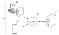
図1は、本発明の一実施形態による拡張現実提供システムの構成を示した図面である。 FIG. 1 is a drawing showing a configuration of an augmented reality providing system according to an embodiment of the present invention.
図1を参照すれば、本発明の一実施形態による拡張現実提供システムは、サーバ10、ユーザ端末20、及びそれらを連結するネットワーク30を含む。
Referring to FIG. 1, the augmented reality providing system according to the embodiment of the present invention includes a
本発明の一実施形態によって提供される拡張現実提供システムは、カメラによって撮影される映像にオブジェクトを重畳し、リアルタイムで表示する拡張現実を提供する。詳細には、一実施形態によって提供される拡張現実は、ユーザ端末20周辺に実際に存在する平面を認識し、認識された平面の属性を決定し、それによる仮想のオブジェクトを、カメラによって撮影される映像と共にリアルタイムで表示する。
The augmented reality providing system provided by one embodiment of the present invention provides augmented reality in which an object is superimposed on an image captured by a camera and displayed in real time. In particular, the augmented reality provided by one embodiment recognizes a plane that actually exists around the
サーバ10は、拡張現実を提供するためのプログラムを、ユーザ端末20に提供する。ユーザ端末20は、サーバ10からプログラムを提供されてインストールし、インストールされたプログラムを利用し、ユーザに拡張現実を提供することができる。
The
ユーザ端末20は、本発明の一実施形態によって提供される拡張現実提供プログラムがインストールされるいかなる端末でも可能である。ユーザ端末20は、携帯用端末でもある。図1においては、携帯用端末が、スマートフォン(smart phone)として図示されているが、本発明の思想は、それに制限されるものではなく、前述のように、コンピュータプログラムのインストール可能な端末であるならば、制限なしに借用されるのである。例えば、ユーザ端末20は、ウェアラブルコンピュータ、HMD(head mounted display)などを含む。
The
ユーザ端末20は、画面を表示する表示部、及び映像を撮影するカメラを含む。該表示部は、映像を直接表示する表示パネルを具備することもできるが、それに限定されるものではなく、プロジェクタ方式の表示装置も該当する。ユーザ端末20は、距離センサ及び方向センサをさらに含んでもよい。
The
ネットワーク30は、ユーザ端末20とサーバ10とを連結する役割を遂行する。例えば、ネットワーク30は、ユーザ端末20がサーバ10に接続した後、パケットデータを送受信することができるように接続経路を提供する。
The
図面には図示されていないが、本発明の一実施形態によるサーバ10は、メモリ、入出力部、プログラム保存部、制御部などを含んでもよい。
Although not shown in the drawings, the
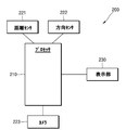
図2は、本発明の一実施形態による拡張現実提供装置200の構成を図示したものである。
FIG. 2 illustrates the configuration of the augmented
本発明の一実施形態による拡張現実提供装置200は、データを処理するプロセッサ(processor)を含む全種の装置に該当する。例えば、拡張現実提供装置200は、少なくとも1以上のプロセッサを含んでもよい。ここで、「プロセッサ」は、例えば、プログラム内に含まれたコードまたは命令によって表現された機能を遂行するために、物理的に構造化された回路を有する、ハードウェアに内蔵されたデータ処理装置を意味する。そのように、ハードウェアに内蔵されたデータ処理装置の一例として、マイクロプロセッサ(microprocessor)、中央処理装置(CPU:central processing unit)、プロセッサコア(processor core)、マルチプロセッサ(multiprocessor)、ASIC(application-specific integrated circuit)、FPGA(field programmable gate array)のような処理装置を網羅することができるが、本発明の範囲は、それらに限定されるものではない。それにより、拡張現実提供装置200は、マイクロプロセッサや汎用コンピュータシステムのような他のハードウェア装置に含まれた形態によっても駆動される。拡張現実提供装置200は、図1に図示されたユーザ端末20にも搭載される。
The augmented
図2に図示された拡張現実提供装置200は、本実施形態の特徴が不明確になることを防止するために、本実施形態と係わる構成要素のみを図示したものである。従って、図2に図示された構成要素以外に、他の汎用的な構成要素がさらに含まれてもよいということは、本実施形態と係わる技術分野において当業者であるならば、理解することができるであろう。
The augmented
例えば、拡張現実提供装置200は、他のネットワーク装置(例えば、サーバ10)と、有無線連結を介して信号を送受信するために必要なハードウェア及びソフトウェアを含む通信部をさらに含んでもよい。
For example, the augmented
また、拡張現実提供装置200は、拡張現実提供装置200が処理するデータを、一時的または永久に保存する機能を遂行するメモリをさらに含んでもよい。該メモリは、磁気記録媒体(magnetic storage media)またはフラッシュ記録媒体(flash storage media)を含んでもよいが、本発明の範囲は、それらに限定されるものではない。
Further, the augmented
本発明の一実施形態による拡張現実提供装置200は、プロセッサ210を利用し、距離センサ221の測定値によって平面を認識し、方向センサ222の測定値を利用し、平面の属性を決定し、それによる仮想のオブジェクトを、カメラ223によって撮影される映像と共に、表示部230にリアルタイムで表示する。
The augmented
図2を参照すれば、本発明の一実施形態による拡張現実提供装置200は、プロセッサ210、距離センサ221、方向センサ222、カメラ223及び表示部230を含む。
Referring to FIG. 2, the augmented
距離センサ221は、距離センサから前方の複数ポイントまでの距離を獲得する。距離センサ221は、複数のポイントに対する方向情報をさらに獲得する。前方に平面が存在する場合、距離センサ221は、平面上の複数のポイントまでの距離及び方向を獲得することができ、プロセッサ210は、距離センサ221が測定した情報を利用し、複数のポイントを含む平面情報、例えば、平面を定義することができる情報として、平面方程式、平面ベクトルなどを獲得することができる。
The
距離センサ221は、例えば赤外線センサであり、赤外線センサから複数のポイントまでの距離を測定することができる。該赤外線センサは、赤外線を送信した後、反射されて戻って来る赤外線を受光し、赤外線が反射された地点までの距離を測定する。距離センサ221は、例えば超音波センサであってもよい。該超音波センサは、超音波を送信した後、反射されて戻って来る超音波を受信し、超音波が反射された地点までの距離を測定する。
The
一例によれば、距離センサ221は、赤外線を発光させる発光部と、反射される赤外線を受光する受光部と、を含む。一例によれば、距離センサ221は、赤外線を第1方向に送信した後、反射された赤外線を受光することにより、距離センサ221から第1方向に位置する第1ポイントまでの距離を測定し、赤外線を第2方向に送信した後、反射される赤外線を受光することにより、距離センサ221から第2方向に位置する第2ポイントまでの距離を測定することができる。距離センサ221は、そのような過程を反復し、複数のポイントまでの距離を各方向について測定することができる。
According to one example, the
距離センサ221が赤外線を発光させる方向は、既設定条件によって可変に設定されてもよい。距離センサ221は、発光方向の調節が可能な1つの発光部を具備してもよいし、あるいは複数の発光部を具備してもよい。
The direction in which the
方向センサ222は、ユーザ端末20が向かう方向を測定する。方向センサ222は、例えば、加速度センサ、角速度センサ、地磁界センサ、またはそれらのうち少なくとも2つの組み合わせでもある。該方向センサは、重力方向を認識し、重力方向を基準に、端末が向かう方向を測定することができる。ただし、該重力方向は、基準方向の例示であるので、それに限定されるものではない。
The
カメラ223は、映像を撮影する。表示部230は、ディスプレイパネルを含み、プロセッサ210の制御によって映像を表示する。
The
本発明の一実施形態によれば、カメラ223と距離センサ221は、同一方向に向けて設置される。それにより、カメラ223によって撮影された映像と、距離センサ221によって獲得された情報との連繋が容易になり、距離センサ221によって獲得された情報に基づいて生成されたオブジェクトを、カメラ223によって撮影された映像と重畳し、表示する拡張現実の提供が容易になる。
According to one embodiment of the present invention, the
カメラ223と距離センサ221とが異なる方向に向けて設置される場合には、距離センサ221によって獲得された情報を、カメラ223の設置方向を基準に変換するには追加的な作業が要求される。
When the
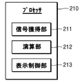
図3は、図2に図示されたプロセッサ210の構成を示したブロック図である。
FIG. 3 is a block diagram showing the configuration of the
図3を参照すれば、プロセッサ210は、信号獲得部211、演算部212及び表示制御部213を含む。図3に図示されたプロセッサ210に含まれたそれぞれのブロックは、1つのプロセッサ上でいずれも具現され、機能によって区分されるものでもあるが、それに限定されるものではなく、それぞれ別個のプロセッサ上にも具現されるということは言うまでもない。また、それぞれのブロックの機能は、1つのプログラムコードを介して、統合的にも具現されるが、各ブロックの機能が別個のプログラムコードに作成され、各プログラムコードが連繋され、図3に図示されたプロセッサ210、及び図2に図示された拡張現実提供装置200が、拡張現実を提供する方式によっても具現される。
Referring to FIG. 3, the
以下では、図2及び図3を共に参照し、本発明の実施形態について説明する。 Hereinafter, embodiments of the present invention will be described with reference to both FIGS. 2 and 3.
一実施形態による信号獲得部211は、距離センサ221、方向センサ222、カメラ223から信号を獲得する。
The
一実施形態による演算部212は、信号獲得部211が獲得した信号を処理する。例えば、信号獲得部211は、複数のポイントに係わる距離(distance)を、距離センサ221から獲得し、演算部212は、獲得された距離を利用し、複数のポイントを含む平面に係わる平面情報を獲得する。該平面情報は、距離センサ221が設置された方向を基準にする平面の方向情報であり、平面方程式、平面ベクトルなどの形態によって表現されてもよい。複数のポイントから平面情報を獲得する演算は、RANSAC(random sample consensus)技法を利用することができるが、それに限定されるものではない。
The
一例によれば、演算部212は、信号獲得部211が獲得した複数のポイントに係わる距離のうち、一部のポイントに係わる距離を利用し、一部のポイントを含む平面に係わる平面情報を獲得する。例えば、第1ポイントと第2ポイントとの方向が類似しているにもかかわらず、第1ポイントまでの距離と、第2ポイントまでの距離との差が大きい場合、第1ポイントと第2ポイントは、他の平面に存在する可能性が高い。第2ポイントと第3ポイントとの方向が類似しており、第2ポイントまでの距離と、第3ポイントまでの距離との差が小さい場合、第2ポイントと第3ポイントは、同じ平面に存在する可能性が高い。従って、演算部212は、複数のポイントのうち、距離センサ221からの距離が類似した一部のポイントを抽出し、抽出された一部のポイントまでの距離を利用し、平面情報を獲得することができる。例えば、演算部212は、複数のポイントのうち、3個以上のポイントまでの距離の差が既設定の臨界値未満である場合、当該3個以上のポイントの距離を利用し、平面情報を獲得する。例えば、演算部212は、第1ポイント、第2ポイント及び第3ポイントそれぞれの距離差が、いずれも既設定の臨界値未満である場合、第1ポイント、第2ポイント及び第3ポイントを含む平面に係わる平面情報を獲得する。
According to one example, the
信号獲得部211は、方向センサ222によって測定された端末の方向情報を獲得し、演算部212は、先立って獲得した平面情報と、端末の方向情報とを利用し、平面のノーマルベクトルを獲得する。詳細には、演算部212は、平面情報の基準方向を、端末の方向(または、端末に設置された距離センサ221が向かう方向)から方向センサ222の基準方向に変換する。詳細には、演算部212は、端末の方向を基準に獲得された平面の方向情報を、方向センサ222によって測定された端末の方向情報(加速度センサによって認識される重力方向を基準にする)を利用して移動させることにより、最終的に、重力方向を基準にする平面の方向情報を獲得する。そのように獲得された重力方向基準平面の方向情報は、平面のノーマルベクトルと見ることができる。
The
演算部212は、平面のノーマルベクトルを考慮し、平面に表示するオブジェクトのパラメータを決定する。該オブジェクトは、複数のパラメータを含んでもよい。該パラメータは、例えば、オブジェクトの色相、勾配(偏り)、カテゴリー、種類、方向、及びオブジェクトに適用されるアニメーションでもある。例えば、演算部212は、平面のノーマルベクトルの方向に対応するように、オブジェクトの偏りを設定することができる。
The
演算部212は、平面のノーマルベクトルを考慮し、平面の属性を区分することができる。また、演算部212は、平面の属性を考慮し、オブジェクトのパラメータを決定することができる。平面の属性は、例えば、平面の種類であり、床、壁、天井にも区分される。演算部212は、平面が床であるか、壁であるか、あるいは天井であるかということにより、オブジェクトのパラメータを異ならせて決定することができる。例えば、演算部212は、平面が壁である場合、平面を突き抜ける経路でオブジェクトが移動するように、アニメーションパラメータを設定することができる。演算部212は、平面が床である場合、床上で床と平行に移動するアニメーションパラメータを設定することができる。
The
演算部212は、平面のノーマルベクトルによって決定された平面の属性と、平面の方向情報(端末方向を基準にする)とをそれぞれ考慮し、オブジェクトのパラメータを決定することができる。例えば、演算部212は、平面の属性により、オブジェクトの第1パラメータを決定し、平面のノーマルベクトルにより、オブジェクトの第2パラメータを決定することができる。例えば、演算部212は、平面の属性により、オブジェクトの色相を決定し、平面の方向に沿って、オブジェクトの偏りを決定することができる。該オブジェクトがアイコンである場合、演算部212は、平面の種類により、アイコンの色相を異ならせて決定し、平面の方向に沿って、アイコンの偏りを決定することができる。該偏りは、三次元のアイコン表示情報を二次元にレンダリングして表示するための偏りであるか、あるいはアイコンの横縦表示比でもある。
The
本発明の一実施形態による拡張現実は、家具配置シミュレーションを提供することができる。オブジェクトは、家具でもある。その場合、演算部212は、平面の属性によってオブジェクトの種類を決定し、平面の方向に沿って、オブジェクトのレンダリング方向を決定することができる。例えば、平面属性が「床」である場合、演算部212は、オブジェクトの種類を、床に配置可能な家具、例えば、テーブル、椅子、ソファ、ベッドなどに決定し、平面の方向に沿って、オブジェクトの表示方向を決定することができる。オブジェクトの表示方向は、三次元の家具表示情報を二次元にレンダリングして表示するためのものでもあるが、それに限定されるものではなく、二次元の家具表示情報を回転及び/またはスケーリングして表示するためのものでもある。
Augmented reality according to one embodiment of the present invention can provide furniture placement simulation. Objects are also furniture. In that case, the
本発明の一実施形態による信号獲得部211は、カメラ223から映像を獲得し、表示制御部213は、獲得された映像を表示部230に表示する。演算部212は、オブジェクトのパラメータを決定するために、信号獲得部211が獲得した映像をさらに利用することができる。例えば、演算部212は、カメラ223によって撮影される映像が分析し、平面のテクスチャを決定することができる。演算部212は、距離センサ221によって認識された複数のポイントの色相を、カメラ223から獲得された映像から抽出し、抽出された色相情報を利用し、平面の色相を決定することができ、平面のテクスチャを決定することができる。演算部212は、抽出された色相情報を利用し、オブジェクトのパラメータを決定することができる。演算部212は、平面の色相またはテクスチャにより、オブジェクトのパラメータを決定することができる。例えば、平面のテクスチャにより、オブジェクトのアニメーションを決定することができる。例えば、平面のテクスチャがつるつるした滑らかな表面を有している場合、オブジェクトに滑るアニメーションを設定することができる。演算部212は、平面の色相により、オブジェクトの色相を決定することができる。演算部212は、空間に含まれた複数の平面の色相を考慮し、全体空間のコンセプトが分類することができ、分類されたコンセプトに該当するオブジェクトを選択することができる。
The
一実施形態による表示制御部213は、ユーザ端末20に具備されるカメラ223によって撮影される映像を、リアルタイムで表示部230に表示する。表示制御部213は、カメラ223によって撮影される映像と、オブジェクトとを重畳して表示することにより、拡張現実を提供することができる。表示制御部213は、カメラ223によって撮影される映像において、演算部212によって認識された平面に該当する領域に、オブジェクトを重畳して表示する。カメラ223と距離センサ221とが同一方向に向けて設置される場合、距離センサ221は、カメラ223によって撮影される平面を認識する。従って、表示制御部213は、カメラ223によって撮影された平面を表示しながら、距離センサ221の測定値を基に獲得された当該平面の情報に基づいて決定されたオブジェクトのパラメータにより、オブジェクトを共に表示することにより、拡張現実を提供することができる。
The
該オブジェクトは、二次元または三次元のイメージ、静的/動的アイコンに該当し、複数のパラメータ値を有する。オブジェクトのパラメータは、平面情報によって設定されるので、平面情報により、オブジェクトが異なるようにも表示される。表示制御部213は、オブジェクトのパラメータを参照し、オブジェクトを表示する。表示制御部213は、オブジェクトのレンダリング方向パラメータに基づいて、オブジェクトを表示するための三次元情報を、当該レンダリング方向に沿って、二次元にレンダリングし、表示部230に表示することができる。
The object corresponds to a two-dimensional or three-dimensional image, static / dynamic icon, and has a plurality of parameter values. Since the parameters of the object are set by the plane information, the object is displayed differently depending on the plane information. The
一実施形態によれば、演算部212は、属性が「壁」である平面に対して表示するオブジェクトを「鏡」と決定することができる。その場合、表示制御部213は、当該平面に対して、鏡オブジェクトを表示し、鏡オブジェクト内部には、前面カメラによって撮影される映像をリアルタイムで表示することができる。
According to one embodiment, the
オブジェクトのパラメータがアニメーションを含む場合、表示制御部213は、アニメーションを適用し、オブジェクトを表示する。例えば、「壁」属性の平面に対し、壁を突き抜けるアニメーションが設定されたオブジェクトを表示する場合、表示制御部213は、オブジェクトに対して不透明な仮想レイヤを平面に重ねて表示し、該オブジェクトを、仮想レイヤの後ろから前に移動させて表示することにより、該オブジェクトが平面を突き抜けるようなアニメーションを表示する。該仮想レイヤは、該オブジェクト以外の他の表示については、透明にも設定される。
When the parameter of the object includes an animation, the
一実施形態によれば、演算部212は、「天井」属性の平面について、日、月、星のイメージを表示するオブジェクトを設定することができる。一実施形態によれば、演算部212は、複数の平面間を移動するオブジェクトを設定することができる。例えば、「天井」属性の平面から「床」属性の平面に向けて移動する水玉オブジェクトを設定することができる。該水玉オブジェクトは、「床」属性の平面に逹すれば、当該平面と同一方向に散らばるアニメーションを含んでもよい。
According to one embodiment, the
図4は、本発明の一実施形態による拡張現実提供方法を図示したフローチャートである。 FIG. 4 is a flowchart illustrating a method for providing augmented reality according to an embodiment of the present invention.
図4に図示されたフローチャートは、図2及び図3に図示されたプロセッサにおいて、時系列的に処理される段階によって構成される。従って、以下において省略された内容であるとしても、図2及び図3で図示された構成について、以上で記述された内容は、図4に図示されたフローチャートにも適用されるということが分かる。 The flowchart illustrated in FIG. 4 is composed of steps that are processed in chronological order in the processors illustrated in FIGS. 2 and 3. Therefore, even if the contents are omitted below, it can be seen that the contents described above with respect to the configurations shown in FIGS. 2 and 3 are also applied to the flowchart shown in FIG.
図4を参照すれば、段階S41において、演算部212は、複数のポイントに係わる距離を利用し、複数のポイントを含む平面に係わる平面情報を獲得する。演算部212は、複数のポイントに係わる方向をさらに利用することができる。
Referring to FIG. 4, in step S41, the
段階S42において、演算部212は、方向センサ222によって測定された端末の方向情報、及び段階S41で獲得された平面情報を利用し、平面のノーマルベクトルを獲得する。
In step S42, the
段階S43において、演算部212は、平面のノーマルベクトルを考慮し、オブジェクトのパラメータを決定する。
In step S43, the
段階S44において、表示制御部213は、端末の表示部230にオブジェクトを表示する。
In step S44, the
図5は、図2の拡張現実提供装置200が平面を認識する方法について説明するための図面である。
FIG. 5 is a drawing for explaining how the augmented
図5を参照すれば、ユーザ端末20が、三次元空間内に具備され、ユーザ端末20に具備される拡張現実提供装置200により、三次元空間を認識する方法が図示されている。ユーザ端末20が自由に方向を変更する間、ユーザ端末20に具備される拡張現実提供装置200は、複数の平面を認識することができ、複数の平面を含む空間を認識することができる。図5には、第1平面P1、第2平面P2及び第3平面P3が図示されている。
Referring to FIG. 5, a method is illustrated in which a
まず、ユーザ端末20が床に向かう間、拡張現実提供装置200が、第3平面P3を認識する実施形態について説明する。ユーザ端末20が床に向かうことになれば、ユーザ端末20の背面に具備される距離センサは、床に位置する複数のポイントS1,S2,S3,S4までの距離及び方向を測定する。拡張現実提供装置200は、複数のポイントS1,S2,S3,S4までの距離及び方向の情報を組み合わせ、複数のポイントS1,S2,S3,S4をいずれも含む第3平面P3を定義し、第3平面P3の方向情報を獲得する。該方向情報は、平面方程式または平面ベクトルによっても表現されるが、それに限定されるものではなく、空間上で平面を定義することができるいかなる情報でも可能である。
First, an embodiment in which the augmented
一方、ユーザ端末20を基準に測定された複数ポイントS1,S2,S3,S4の距離及び方向の情報を基に獲得された第3平面P3の方向情報は、ユーザ端末20が向かう方向を基準にする。従って、ユーザ端末20に具備された方向センサによって測定された地表面基準端末方向情報を考慮し、第3平面P3の方向情報を変換すれば、地表面を基準にする第3平面P3に係わる第3ノーマルベクトルN3を獲得することができる。詳細には、ユーザ端末20の方向を基準にする第3平面P3の方向情報に、地表面(または、重力方向)を基準にするユーザ端末20の方向情報を加え、地表面(または、重力方向)を基準にする第3平面P3の第3ノーマルベクトルN3値を獲得することができる。方向センサは、重力加速度を認識する加速度センサでもあるが、それに限定されるものではなく、加速度センサ及びジャイロセンサのうち1以上の組み合わせによって形成された3軸,6軸または9軸センサでもある。
On the other hand, the direction information of the third plane P3 acquired based on the distance and direction information of the plurality of points S1, S2, S3, S4 measured with respect to the
前述のような方法で、ユーザ端末20の方向を変更しながら、第1平面P1に係わる第1ノーマルベクトルN1、第2平面P2に係わる第2ノーマルベクトルN2をさらに獲得することができる。
By the method as described above, the first normal vector N1 related to the first plane P1 and the second normal vector N2 related to the second plane P2 can be further acquired while changing the direction of the
拡張現実提供装置200の演算部212は、各平面のノーマルベクトルにより、各平面の属性を決定する。例えば、ユーザ端末20には、床及び天井のベクトルと、壁のベクトルとが事前に保存されている。
The
例えば、床及び天井のベクトル範囲は、−5〜5゜及び/または175〜185゜であり、壁のベクトル範囲は、85〜95゜及び/または265〜275゜でもある。図5に図示された例によれば、第1ノーマルベクトルN1及び第3ノーマルベクトルN3は、床及び天井のベクトル範囲に属し、第2ノーマルベクトルN2は、壁のベクトル範囲に属する。従って、拡張現実提供装置200は、第1平面P1及び第3平面P3の属性を、床または天井と決定し、第2平面P2の属性を壁と決定する。
For example, the floor and ceiling vector ranges are -5 to 5 ° and / or 175 to 185 °, and the wall vector ranges are also 85 to 95 ° and / or 265 to 275 °. According to the example illustrated in FIG. 5, the first normal vector N1 and the third normal vector N3 belong to the floor and ceiling vector ranges, and the second normal vector N2 belongs to the wall vector range. Therefore, the augmented
または、床及び天井のベクトルが、0゜または180゜と定義され、壁のベクトルが90゜または270゜にも定義される。演算部212は、平面のノーマルベクトルが、誤差範囲内において、既定義ベクトルのうち床及び天井のベクトルと同一である場合、平面の属性を「床または天井」と定義し、誤差範囲内において、壁のベクトルと同一である場合、平面の属性を「壁」と定義する。
Alternatively, the floor and ceiling vectors are defined as 0 ° or 180 °, and the wall vectors are also defined as 90 ° or 270 °. When the normal vector of the plane is the same as the vector of the floor and the ceiling among the defined vectors within the error range, the
演算部212は、平面の属性を決定するために、平面のノーマルベクトルと、既設定特定属性のベクトルとの類似度を算出するために、ベクトル内積演算を行うことができる。そのように、ベクトル間の距離を算出する代わりに、ベクトル内積値を算出し、類似度測定に使用することにより、演算時間を顕著に短縮させることができる。ベクトルが類似するほど、内積値は、1または−1に近くなる。例えば、第2平面P2の第2ノーマルベクトルN2と、既設定「壁」属性のベクトルとの内積の値が、1または−1に対して既設定誤差範囲内に含まれる場合、演算部212は、第2平面P2の属性を「壁」と決定する。
The
拡張現実提供装置200は、第1平面P1及び第3平面P3の属性を、床及び天井のうちいずれか一つに決定するために、各平面の高さ情報、またはユーザ端末20の方向情報を考慮することができる。例えば、各平面の方向情報、及びユーザ端末20の方向情報によって区分される各平面の高さ情報を、端末の高さと比較し、天井と床とを区分することができる。例えば、平面の高さが端末より高い第1平面P1の属性を天井と、平面の高さが端末より低い第3平面P3を床と決定する。または、平面認識時点に、ユーザ端末20の方向が90゜以上である第1平面P1の属性を天井と、平面認識時点に、ユーザ端末20が90゜未満である第3平面P3の属性を床と決定する。
The augmented
図5を参照すれば、拡張現実提供装置200は、平面と平面との交差線を、各平面のエッジ(edge)、すなわち、端と認識することができる。例えば、拡張現実提供装置200は、図5に図示された第1平面P1及び第2平面P2それぞれのノーマルベクトルN1,N2を参照し、第1平面P1と第2平面P2との交差線e1を、第1平面P1と第2平面P2とのエッジと認識する。また、拡張現実提供装置200は、第2平面P2及び第3平面P3それぞれのノーマルベクトルN2,N3を参照し、第2平面P2と第3平面P3との交差線e2を、第2平面P2と第3平面P3とのエッジと認識する。拡張現実提供装置200は、第1ノーマルベクトルN1、第2ノーマルベクトルN2及び第3ノーマルベクトルN3を利用し、三次元空間を認識することができる。
With reference to FIG. 5, the augmented
認識された全ての平面がエッジによって取り囲まれれば、拡張現実提供装置200は、閉空間(closed space)を認識することができる。拡張現実提供装置200は、閉空間を完成させるために、ゲーム要素を利用し、ユーザ端末20の撮影方向を誘導することができる。例えば、拡張現実提供装置200は、エッジで取り囲まれていない平面がある場合、当該平面のエッジで取り囲まれていない部分を示す矢印などを、ユーザ端末20の表示部230に表示したり、ユーザ端末20の表示部230に表示されたキャラクタを、エッジによって取り囲まれていない部分に移動させるアニメーションを適用したりすることができる。
If all the recognized planes are surrounded by edges, the
拡張現実提供装置200は、認識されていない平面を撮影している場合、ユーザが当該方向を続けて撮影するように、当該方向に時間が必要となるゲーム要素を表示することができる。拡張現実提供装置200は、ユーザが、ゲーム要素を進める間、周辺空間を認識する。
When the augmented
拡張現実提供装置200は、平面上にオブジェクトを表示することができる。例えば、床に認識された第3平面P3上で移動するキャラクタを表示することができる。拡張現実提供装置200は、キャラクタが第3平面P3上で移動するとき、距離センサによって認識されたポイントS1,S2,S3,S4間の経路を移動するように設定することができる。
The
図6は、図2の拡張現実提供装置200が平面を認識する方法について説明するための他の図面である。
FIG. 6 is another drawing for explaining how the augmented
図6を参照すれば、床と認識される第3平面P3上に、物体60が置かれており、拡張現実提供装置200は、物体60の上部表面を、第6平面P6と認識することができる。第3平面P3と第6平面P6との属性は、いずれも「床」でもある。そのように、属性が同一である複数の平面が存在する場合、拡張現実提供装置200は、複数の平面間を移動するオブジェクトを提供することができ、移動するとき、アニメーションを適用することができる。例えば、該オブジェクトは、キャラクタであり、該キャラクタが高さが異なる2つの平面P3,P6間を移動するとき、「ジャンプ」アニメーションを適用することができる。
Referring to FIG. 6, the
拡張現実提供装置200は、ユーザのタッチにより、オブジェクトを移動させることができる。該オブジェクトが第3平面P3上を移動しているとき、ユーザが第6平面P6をタッチする場合、該オブジェクトは、タッチされた地点に移動する。ただし、移動経路上において、平面移動があり、移動する平面の高さが異なるので、拡張現実提供装置200は、「ジャンプ」アニメーションを適用する。
The augmented
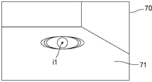
図7及び図8は、拡張現実が提供された画面の例である。 7 and 8 are examples of screens provided with augmented reality.
図7を参照すれば、画面70には、カメラ223によって撮影された画面が表示され、平面71上にオブジェクトi1が重畳されて表示され、拡張現実が提供される。オブジェクトi1のパラメータは、色相及び偏りを含んでもよい。オブジェクトi1の色相は、平面71の属性である「床」に対応する色相に表示され、オブジェクトi1の偏りは、平面71の方向情報によっても設定される。図7においては、平面71の方向に合わせ、オブジェクトi1が偏って楕円形に表示された例が図示されている。
Referring to FIG. 7, the
図8を参照すれば、画面80には、カメラ223によって撮影された画面が表示され、平面81上にオブジェクトi2が重畳されて表示され、拡張現実が提供される。オブジェクトi2のパラメータは、色相及び偏りを含んでもよい。オブジェクトi2の色相は、平面81の属性である「壁」に対応する色相に表示され、オブジェクトi2の偏りは、平面81の方向情報によっても設定される。図8においては、平面81の方向に合わせ、オブジェクトi2が偏って楕円形に表示された例が図示されている。
Referring to FIG. 8, the
図7及び図8を参照すれば、ユーザは、オブジェクトの色相により、オブジェクトが表示された平面の属性を認知することができ、オブジェクトの偏りにより、平面の方向を直観的に認知することができる。 With reference to FIGS. 7 and 8, the user can recognize the attribute of the plane on which the object is displayed by the hue of the object, and can intuitively recognize the direction of the plane by the bias of the object. ..
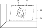
図9A、図9B及び図9Cは、拡張現実が提供された画面の他の例である。 9A, 9B and 9C are other examples of screens provided with augmented reality.
図9A、図9B及び図9Cを参照すれば、画面90には、カメラ223によって撮影された画面が表示され、拡張現実提供装置200によって認識された平面91上に、オブジェクトi3が重畳されて表示され、拡張現実が提供される。オブジェクトi3のパラメータは、キャラクタ表示情報を含んでもよい。図9A、図9B及び図9Cを参照すれば、拡張現実提供装置200は、不透明な仮想レイヤ92を平面91に重ねて表示し、オブジェクトi3を、平面91のノーマルベクトル方向に、例えば、仮想レイヤ92の後ろから前に移動するように表示することにより、オブジェクトi3が平面91を突き抜けるようなアニメーションを表示する。仮想レイヤ92は、オブジェクトi3以外の他の表示については、透明に表示されるようにも設定される。すなわち、仮想レイヤ92は、オブジェクトi3の位置により、オブジェクトi3の表示を隠すことはできるが、それ以外の平面91などの表示を隠さないように設定される。
Referring to FIGS. 9A, 9B and 9C, the
オブジェクトi3が仮想レイヤ92の後ろから前に移動することにより、ユーザ端末20に表示される画面は、図9Aから図9Bに、図9Bから図9Cに順次に変更される。図9Aにおいては、オブジェクトi3が仮想レイヤ92の後ろに存在し、画面90に表示されていない例が図示されている。図9Aにおいては、説明の便宜上、オブジェクトi3は点線で描かれているが、実際には、画面90に表示されない。図9Bにおいては、オブジェクトi3が、仮想レイヤ92の後ろから前に移動する最中の画面が図示されており、オブジェクトi3の一部は、平面91上に表示され、残り一部は、画面90に表示されていない例が図示されている。図9Bにおいては、説明のために、オブジェクトi3の一部を点線で表示しているが、点線で表示された部分は、実際には、画面90に図示されないものでもある。図9Cにおいては、オブジェクトi3が仮想レイヤ92の前に移動し、オブジェクトi3の全体像が平面91上に重畳して表示された例が図示されている。
As the object i3 moves from the back to the front of the
一方、オブジェクトi3は、三次元客体であってもよく、図9A、図9B及び図9Cの例において、オブジェクトi3がユーザ端末20に近くなる方向に移動するので、拡張現実提供装置200は、オブジェクトi3が移動するにつれ、オブジェクトi3の大きさをだんだんと大きく変更して表示することができる。
On the other hand, the object i3 may be a three-dimensional object, and in the examples of FIGS. 9A, 9B, and 9C, the object i3 moves in a direction closer to the
図10は、拡張現実が提供された画面の他の例である。 FIG. 10 is another example of a screen provided with augmented reality.
図10を参照すれば、画面100には、カメラ223によって撮影された画面が表示され、拡張現実提供装置200によって認識された平面101上に、オブジェクトi4が重畳されて表示され、拡張現実が提供される。図10を参照すれば、拡張現実提供装置200は、「壁」と属性が指定された平面101上に「鏡」オブジェクトi4を表示することができる。拡張現実提供装置200は、オブジェクトi4の既設定内部領域に、ユーザ端末20に具備された前面カメラ(図示せず)によって撮影される画面を表示することにより、オブジェクトi4が鏡であるということを示すことができる。
Referring to FIG. 10, the screen taken by the
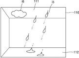
図11は、拡張現実が提供された画面の他の例である。 FIG. 11 is another example of a screen provided with augmented reality.
図11を参照すれば、画面110には、カメラ223によって撮影された画面が表示され、拡張現実提供装置200によって認識された平面111,112情報により、画面110に、オブジェクトi5が重畳されて表示されて拡張現実が提供される。図11を参照すれば、拡張現実提供装置200は、「天井」と属性が指定された平面111から、「床」と属性が指定された平面112に向けて移動するオブジェクトi5を表示することができる。図11に図示された矢印は、説明の便宜のために、オブジェクトi5に含まれた複数要素(雨粒)が移動する経路を示したものであり、画面110に表示されるものではない。図11を参照すれば、オブジェクトi5の要素は、平面111から平面112に移動し、平面112に至れば、平面112の同一方向で散らばった後、フェードアウト(fade-out)されて消えるアニメーションが表示されることにより、雨粒が床に散らばるような表示効果が具現される。
Referring to FIG. 11, the screen taken by the
図11を参照すれば、拡張現実提供装置200は、「天井」と属性が指定された平面111上に、オブジェクトi6をさらに重畳して表示することができる。図11に図示されているように、拡張現実提供装置200は、複数のオブジェクトを共に表示することができる。
Referring to FIG. 11, the augmented
一方、一例によれば平面111には、前述の仮想レイヤが表示され、オブジェクトi5の要素は、平面111に対応する仮想レイヤの後ろから前に移動するようにも表示される。他の例によれば、オブジェクトi5の要素は、オブジェクトi6の後ろから前に移動するようにも表示される。オブジェクトi6は、オブジェクトi5に対して不透明に設定されてもよく、オブジェクトi5だけではなく、画面110に表示される他の部分、例えば、平面110についても不透明に設定されてもよい。
On the other hand, according to one example, the virtual layer described above is displayed on the
一方、図4に図示された本発明の一実施形態による拡張現実提供方法は、コンピュータで実行されるプログラムによって作成可能であり、コンピュータで読み取り可能な記録媒体を利用し、前記プログラムを動作させる汎用デジタルコンピュータにおいても具現される。 On the other hand, the augmented reality providing method according to the embodiment of the present invention shown in FIG. 4 can be created by a program executed by a computer, and a general-purpose method for operating the program by using a computer-readable recording medium is used. It is also embodied in digital computers.
媒体は、コンピュータで実行可能なプログラムを続けて保存したり、実行またはダウンロードのために臨時保存したりするものであってもよい。また、該媒体は、単一または数個のハードウェアが結合された形態の多様な記録手段または保存手段でもあるが、あるコンピュータシステムに直接接続される媒体に限定されるものではなく、ネットワーク上に分散存在するものであってもよい。該媒体の例示としては、ハードディスク、フロッピィーディスク及び磁気テープのような磁気媒体;CD−ROM及びDVDのような光記録媒体;フロプティカルディスク(floptical disk)のような磁気・光媒体(magneto-optical medium);及びROM、RAM、フラッシュメモリなどを含み、プログラム命令語が保存されるように構成されたものがある。また、他の媒体の例示として、アプリケーションを流通するアプリストアや、その他多様なソフトウェアを供給あるいは流通するサイト、サーバなどで管理する記録媒体ないし記録媒体も挙げることができる。 The medium may be one that continuously stores a program that can be executed on a computer, or that it is temporarily stored for execution or download. The medium is also a variety of recording or storage means in the form of a single piece or a combination of several pieces of hardware, but is not limited to a medium directly connected to a computer system, and is not limited to a medium. It may be distributed in the environment. Examples of such media include magnetic media such as hard disks, floppy disks and magnetic tapes; optical recording media such as CD-ROMs and DVDs; magnetic / optical media such as floptical disks. Optical medium); and some include ROM, RAM, flash memory, etc., and are configured to store program commands. Further, as an example of other media, a recording medium or a recording medium managed by an app store that distributes applications, a site that supplies or distributes various other software, a server, or the like can be mentioned.
以上、本発明に対してその望ましい実施形態を中心に述べた。本発明は、図面に図示された実施形態を参照して説明されたが、それらは、例示的なものに過ぎず、本発明が属する技術分野において当業者であるならば、本発明が、本発明の本質的な特性から外れない範囲で変形された形態にも具現され、均等な他の実施例が可能であるということを理解することができるであろう。従って、開示された実施形態は、限定的な観点ではなく、説明的な観点から考慮されなければならない。本発明の範囲は、前述の説明ではなく特許請求の範囲に示されており、それと同等な範囲内にある全ての差異は、本発明に含まれたものであると解釈されなければならないのである。 In the above, the desirable embodiment of the present invention has been mainly described. The present invention has been described with reference to embodiments illustrated in the drawings, but they are merely exemplary and if one of ordinary skill in the art to which the present invention belongs, the present invention is the present invention. It will be appreciated that other uniform embodiments are possible, embodied in modified forms to the extent that they do not deviate from the essential properties of the invention. Therefore, the disclosed embodiments must be considered from a descriptive point of view, not from a limiting point of view. The scope of the invention is set forth in the claims rather than the description above, and all differences within the equivalent scope must be construed as included in the invention. ..
本発明は、拡張現実を利用することができる多様な分野に適用されることができる。例えば、ゲーム、放送、建築設計、自動車、インテリア、製造工程管理、モバイルソリューション、教育など多様な分野に適用可能である。 The present invention can be applied to various fields in which augmented reality can be utilized. For example, it can be applied to various fields such as games, broadcasting, architectural design, automobiles, interiors, manufacturing process management, mobile solutions, and education.
以上では、本発明の例示的な実施形態を参照して説明したが、当該技術分野において当業者であるならば、特許請求の範囲に記載された本発明の思想及び領域から外れない範囲内において、本発明を多様に修正及び変更させるということを理解することができるであろう。 Although the above description has been made with reference to the exemplary embodiments of the present invention, those skilled in the art will be within the scope of the idea and domain of the present invention described in the claims. , It will be understood that the present invention is modified and modified in various ways.
Claims (18)
方向センサによって測定された端末の方向情報、及び前記平面情報を利用して、前記平面のノーマルベクトルを獲得する段階であって、前記平面の方向情報の基準を、前記端末の方向から前記方向センサの基準方向に変換し、前記ノーマルベクトルを獲得する段階と、
前記ノーマルベクトルに基づいて、空間を限定する所定の複数の属性のうち前記平面の属性が何であるかを決定し、前記平面に表示するオブジェクトの動きが、前記平面の決定された属性に応じているように、前記オブジェクトのパラメータを決定する段階と、
前記端末の表示部に、前記決定されたパラメータにより、前記オブジェクトを表示する段階と、
を含む拡張現実提供方法をコンピュータに実行させるコンピュータプログラム。 The distance to a plurality of points around the terminal measured from the terminal, the method comprising: acquiring plane information, the direction of the terminal as a reference the direction information of the plane containing the points of multiple,
Direction information of the terminal that is determined by the direction sensor, and by using the plane information, the direction sensor comprising the steps of acquiring a normal vector of the plane, the reference direction information of the plane, the direction of the terminal At the stage of converting to the reference direction of and acquiring the normal vector ,
Based on the normal vector , it is determined what is the attribute of the plane among a plurality of predetermined attributes that limit the space, and the movement of the object displayed on the plane depends on the determined attribute of the plane. As you can see, the stage of determining the parameters of the object,
The stage of displaying the object on the display unit of the terminal according to the determined parameter, and
A computer program that causes a computer to execute augmented reality delivery methods, including.
前記平面情報を獲得する段階は、前記測定された距離及び方向を利用し、前記平面情報を獲得することを特徴とする請求項1に記載のコンピュータプログラム。 Further including the step of acquiring the distance and direction from the infrared sensor measured from the infrared sensor to a plurality of points.
The computer program according to claim 1, wherein the step of acquiring the plane information is to acquire the plane information by using the measured distance and direction.
前記表示する段階は、前記オブジェクトを表示するための三次元情報を、前記レンダリング方向に沿って、二次元にレンダリングして表示することを特徴とする請求項4又は5に記載のコンピュータプログラム。 The step of pre-Symbol decision, based on the attribute to determine the type of the object, based on the direction information of the plane, determining the rendering direction of said object,
The computer program according to claim 4 or 5, wherein the display step is to render and display three-dimensional information for displaying the object in two dimensions along the rendering direction.
前記カメラ及び前記距離センサは、同一方向に向けて設置されることを特徴とする請求項7に記載のコンピュータプログラム。 The distance is measured by a distance sensor provided in the terminal.
The computer program according to claim 7 , wherein the camera and the distance sensor are installed facing in the same direction.
方向センサによって測定された端末の方向情報、及び前記平面情報を利用して、前記平面のノーマルベクトルを獲得する段階であって、前記平面の方向情報の基準を、前記端末の方向から前記方向センサの基準方向に変換し、前記ノーマルベクトルを獲得する段階と、
前記ノーマルベクトルに基づいて、空間を限定する所定の複数の属性のうち前記平面の属性が何であるかを決定し、前記平面に表示するオブジェクトの動きが、前記平面の決定された属性に応じているように、前記オブジェクトのパラメータを決定する段階と、
前記端末の表示部に、前記決定されたパラメータにより、前記オブジェクトを表示する段階と、を含む拡張現実提供方法。 The distance to a plurality of points around the terminal measured from the terminal, the method comprising: acquiring plane information, the direction of the terminal as a reference the direction information of the plane containing the points of multiple,
Direction information of the terminal that is determined by the direction sensor, and by using the plane information, the direction sensor comprising the steps of acquiring a normal vector of the plane, the reference direction information of the plane, the direction of the terminal At the stage of converting to the reference direction of and acquiring the normal vector ,
Based on the normal vector , it is determined what is the attribute of the plane among a plurality of predetermined attributes that limit the space, and the movement of the object displayed on the plane depends on the determined attribute of the plane. As you can see, the stage of determining the parameters of the object,
A method for providing augmented reality, which includes a step of displaying the object on the display unit of the terminal according to the determined parameter.
前記距離を利用し、前記複数のポイントを含む平面の方向情報である平面情報を、前記端末の方向を基準として獲得し、前記端末の方向情報、及び前記平面情報を利用し、前記平面のノーマルベクトルを獲得し、前記ノーマルベクトルを考慮し、前記平面に表示するオブジェクトのパラメータを決定する演算部と、
前記端末の表示部に、前記決定されたパラメータにより、前記オブジェクトを表示する表示制御部と、を含み、
前記演算部は、前記平面の方向情報の基準を前記端末の方向から前記方向センサの基準方向に変換することにより獲得したノーマルベクトルに基づいて、空間を限定する所定の複数の属性のうち前記平面の属性が何であるかを決定し、前記平面に表示するオブジェクトの動きが、前記平面の決定された属性に応じているように、前記オブジェクトのパラメータを決定する、拡張現実提供装置。 A signal acquisition unit for acquiring from a terminal that is measured by the distance sensor direction information of the terminal that is measured by the distance, and the direction sensor to a plurality of points around the terminal,
Utilizing said distance, the plane information is direction information of the plane including the plurality of points, won direction of the terminal as a reference, the direction information of the terminal, and using the plan information, the normal of the plane An arithmetic unit that acquires a vector, considers the normal vector, and determines the parameters of the object to be displayed on the plane.
On the display unit of the terminal, by the determined parameter, saw including a display control unit that displays the object,
The calculation unit has the plane among a plurality of predetermined attributes that limit the space based on the normal vector acquired by converting the reference of the direction information of the plane from the direction of the terminal to the reference direction of the direction sensor. An augmented reality provider that determines what the attributes of an object are and determines the parameters of the object such that the movement of the object displayed on the plane corresponds to the determined attributes of the plane.
加速度センサ及びジャイロセンサのうち1以上を含む前記方向センサをさらに含むことを特徴とする請求項11に記載の拡張現実提供装置。 The augmented reality providing device is
Providing augmented reality device according to claim 11, wherein the further including said direction sensor comprising one or more of an acceleration sensor and a gyro sensor.
前記表示制御部は、前記オブジェクトを表示するための三次元情報を、前記レンダリング方向に沿って、二次元にレンダリングして表示することを特徴とする請求項13又は14に記載の拡張現実提供装置。 Before SL calculating unit, based on the attribute to determine the type of the object, based on the direction information of the plane, determining the rendering direction of said object,
The augmented reality providing device according to claim 13, wherein the display control unit renders and displays three-dimensional information for displaying the object in two dimensions along the rendering direction. ..
前記カメラと、
前記距離センサと、をさらに含み、
前記カメラ及び前記距離センサは、同一方向に向けて設置されることを特徴とする請求項16に記載の拡張現実提供装置。 The augmented reality providing device is
With the camera
Further including the distance sensor,
The augmented reality providing device according to claim 16, wherein the camera and the distance sensor are installed facing in the same direction.
Applications Claiming Priority (1)
| Application Number | Priority Date | Filing Date | Title |
|---|---|---|---|
| PCT/KR2017/002373 WO2018164287A1 (en) | 2017-03-06 | 2017-03-06 | Method and device for providing augmented reality, and computer program |
Publications (3)
| Publication Number | Publication Date |
|---|---|
| JP2020509505A JP2020509505A (en) | 2020-03-26 |
| JP2020509505A5 JP2020509505A5 (en) | 2020-11-05 |
| JP6980802B2 true JP6980802B2 (en) | 2021-12-15 |
Family
ID=63448162
Family Applications (1)
| Application Number | Title | Priority Date | Filing Date |
|---|---|---|---|
| JP2019548040A Active JP6980802B2 (en) | 2017-03-06 | 2017-03-06 | Methods, equipment and computer programs to provide augmented reality |
Country Status (5)
| Country | Link |
|---|---|
| US (2) | US11120629B2 (en) |
| EP (1) | EP3594906B1 (en) |
| JP (1) | JP6980802B2 (en) |
| CN (2) | CN110313021B (en) |
| WO (1) | WO2018164287A1 (en) |
Families Citing this family (3)
| Publication number | Priority date | Publication date | Assignee | Title |
|---|---|---|---|---|
| CN110930488B (en) * | 2019-11-15 | 2023-06-06 | 深圳市瑞立视多媒体科技有限公司 | Fish behavior simulation method, device, equipment and storage medium |
| CN111582418B (en) * | 2020-05-20 | 2022-03-08 | 郝杰 | Sliding display method of AR virtual specification |
| KR20210158695A (en) * | 2020-06-24 | 2021-12-31 | 삼성전자주식회사 | Electronic device and operating method for detecting a plane in an image |
Family Cites Families (26)
| Publication number | Priority date | Publication date | Assignee | Title |
|---|---|---|---|---|
| JPH0518940A (en) * | 1991-07-09 | 1993-01-26 | Aloka Co Ltd | Ultrasonic three-dimensional image display device |
| JPH0998323A (en) * | 1995-09-29 | 1997-04-08 | Matsushita Electric Ind Co Ltd | Video camera |
| JP2004192653A (en) * | 1997-02-28 | 2004-07-08 | Toshiba Corp | Multi-modal interface device and multi-modal interface method |
| JP2002366976A (en) * | 2001-06-08 | 2002-12-20 | Fujitsu Ltd | Program and device for displaying object |
| US8970690B2 (en) * | 2009-02-13 | 2015-03-03 | Metaio Gmbh | Methods and systems for determining the pose of a camera with respect to at least one object of a real environment |
| US20120019441A1 (en) * | 2009-03-26 | 2012-01-26 | Kyocera Corporation | Mobile electronic device |
| KR100982768B1 (en) * | 2009-09-21 | 2010-09-20 | (주)올라웍스 | Method, terminal and computer-readable recording medium for providing different image information based on angle of terminal |
| US8963954B2 (en) * | 2010-06-30 | 2015-02-24 | Nokia Corporation | Methods, apparatuses and computer program products for providing a constant level of information in augmented reality |
| JP5799521B2 (en) * | 2011-02-15 | 2015-10-28 | ソニー株式会社 | Information processing apparatus, authoring method, and program |
| JP5724543B2 (en) * | 2011-03-31 | 2015-05-27 | ソニー株式会社 | Terminal device, object control method, and program |
| KR101971948B1 (en) * | 2011-07-28 | 2019-04-24 | 삼성전자주식회사 | Marker-less augmented reality system using plane feature and method thereof |
| EP2750110B1 (en) * | 2011-08-24 | 2020-03-18 | Sony Corporation | Information processing device, information processing method, and program |
| KR101837107B1 (en) * | 2011-09-01 | 2018-03-09 | 에스케이 텔레콤주식회사 | Terminal And Computer-Readable Recording Medium with Program for Providing Indoor Location Based Services by Using Augmented Reality |
| JP2013225245A (en) * | 2012-04-23 | 2013-10-31 | Sony Corp | Image processing device, image processing method, and program |
| KR101546654B1 (en) * | 2012-06-26 | 2015-08-25 | 한국과학기술원 | Method and apparatus for providing augmented reality service in wearable computing environment |
| US9317972B2 (en) * | 2012-12-18 | 2016-04-19 | Qualcomm Incorporated | User interface for augmented reality enabled devices |
| KR20140145217A (en) * | 2013-05-30 | 2014-12-23 | (주)브이알엑스 | 3d virtual modeling system using spatial information and method thereof |
| US9432636B2 (en) * | 2013-11-26 | 2016-08-30 | Microsoft Technology Licensing, Llc | Large-scale surface reconstruction that is robust against tracking and mapping errors |
| WO2015092905A1 (en) * | 2013-12-19 | 2015-06-25 | 日立マクセル株式会社 | Projection image display device and projection image display method |
| US9953111B2 (en) * | 2014-06-06 | 2018-04-24 | Matterport, Inc. | Semantic understanding of 3D data |
| WO2016012041A1 (en) * | 2014-07-23 | 2016-01-28 | Metaio Gmbh | Method and system for presenting at least part of an image of a real object in a view of a real environment, and method and system for selecting a subset of a plurality of images |
| US20160191877A1 (en) * | 2014-12-25 | 2016-06-30 | Panasonic Intellectual Property Management Co., Ltd. | Projector device and projection method |
| JP2016139199A (en) * | 2015-01-26 | 2016-08-04 | 株式会社リコー | Image processing device, image processing method, and program |
| JP6723798B2 (en) * | 2015-05-20 | 2020-07-15 | キヤノン株式会社 | Information processing device, method, and program |
| KR20170014451A (en) * | 2015-07-30 | 2017-02-08 | 삼성에스디에스 주식회사 | System and method for securing a clear view, and terminal for performing the same |
| US9858683B2 (en) * | 2015-08-05 | 2018-01-02 | Intel Corporation | Method and system of planar surface detection objects in 3d space generated from captured images for image processing |
-
2017
- 2017-03-06 WO PCT/KR2017/002373 patent/WO2018164287A1/en unknown
- 2017-03-06 EP EP17899941.3A patent/EP3594906B1/en active Active
- 2017-03-06 JP JP2019548040A patent/JP6980802B2/en active Active
- 2017-03-06 CN CN201780086884.9A patent/CN110313021B/en active Active
- 2017-03-06 CN CN202310837824.3A patent/CN116863107A/en active Pending
-
2019
- 2019-07-11 US US16/508,830 patent/US11120629B2/en active Active
-
2021
- 2021-08-05 US US17/395,083 patent/US11562545B2/en active Active
Also Published As
| Publication number | Publication date |
|---|---|
| US20190333282A1 (en) | 2019-10-31 |
| CN116863107A (en) | 2023-10-10 |
| EP3594906B1 (en) | 2022-10-19 |
| US20210366199A1 (en) | 2021-11-25 |
| JP2020509505A (en) | 2020-03-26 |
| EP3594906A4 (en) | 2020-11-04 |
| CN110313021A (en) | 2019-10-08 |
| US11120629B2 (en) | 2021-09-14 |
| CN110313021B (en) | 2023-07-25 |
| US11562545B2 (en) | 2023-01-24 |
| WO2018164287A1 (en) | 2018-09-13 |
| EP3594906A1 (en) | 2020-01-15 |
Similar Documents
| Publication | Publication Date | Title |
|---|---|---|
| US10789776B2 (en) | Structural modeling using depth sensors | |
| US9898844B2 (en) | Augmented reality content adapted to changes in real world space geometry | |
| CN105493154B (en) | System and method for determining the range of the plane in augmented reality environment | |
| US8970586B2 (en) | Building controllable clairvoyance device in virtual world | |
| CN103914876B (en) | For showing the method and apparatus of video on 3D maps | |
| US20150185825A1 (en) | Assigning a virtual user interface to a physical object | |
| US9805509B2 (en) | Method and system for constructing a virtual image anchored onto a real-world object | |
| US11263457B2 (en) | Virtual item display simulations | |
| US20180033203A1 (en) | System and method for representing remote participants to a meeting | |
| US20150187137A1 (en) | Physical object discovery | |
| US9268410B2 (en) | Image processing device, image processing method, and program | |
| US20140002443A1 (en) | Augmented reality interface | |
| CN110473293B (en) | Virtual object processing method and device, storage medium and electronic equipment | |
| US20160034137A1 (en) | Reality capture graphical user interface | |
| US11562545B2 (en) | Method and device for providing augmented reality, and computer program | |
| CN104360729A (en) | Multi-interactive method and device based on Kinect and Unity 3D | |
| US20230037750A1 (en) | Systems and methods for generating stabilized images of a real environment in artificial reality | |
| Afif et al. | Orientation control for indoor virtual landmarks based on hybrid-based markerless augmented reality | |
| US9881419B1 (en) | Technique for providing an initial pose for a 3-D model | |
| US11562538B2 (en) | Method and system for providing a user interface for a 3D environment | |
| KR20140001152A (en) | Areal-time coi registration system and the method based on augmented reality | |
| KR20180090499A (en) | Applying method 3D model to goods for augmented reality and virtual reality shopping mall | |
| US20230326147A1 (en) | Helper data for anchors in augmented reality | |
| JP2021124433A (en) | Measurement device, measurement program and measurement method | |
| Lue et al. | 3D whiteboard: collaborative sketching with 3D-tracked smart phones |
Legal Events
| Date | Code | Title | Description |
|---|---|---|---|
| A621 | Written request for application examination |
Free format text: JAPANESE INTERMEDIATE CODE: A621 Effective date: 20200217 |
|
| A521 | Request for written amendment filed |
Free format text: JAPANESE INTERMEDIATE CODE: A523 Effective date: 20200917 |
|
| A131 | Notification of reasons for refusal |
Free format text: JAPANESE INTERMEDIATE CODE: A131 Effective date: 20210413 |
|
| RD03 | Notification of appointment of power of attorney |
Free format text: JAPANESE INTERMEDIATE CODE: A7423 Effective date: 20210414 |
|
| A711 | Notification of change in applicant |
Free format text: JAPANESE INTERMEDIATE CODE: A712 Effective date: 20210412 |
|
| A521 | Request for written amendment filed |
Free format text: JAPANESE INTERMEDIATE CODE: A523 Effective date: 20210601 |
|
| TRDD | Decision of grant or rejection written | ||
| A01 | Written decision to grant a patent or to grant a registration (utility model) |
Free format text: JAPANESE INTERMEDIATE CODE: A01 Effective date: 20211019 |
|
| A61 | First payment of annual fees (during grant procedure) |
Free format text: JAPANESE INTERMEDIATE CODE: A61 Effective date: 20211117 |
|
| R150 | Certificate of patent or registration of utility model |
Ref document number: 6980802 Country of ref document: JP Free format text: JAPANESE INTERMEDIATE CODE: R150 |
|
| S111 | Request for change of ownership or part of ownership |
Free format text: JAPANESE INTERMEDIATE CODE: R313111 |
|
| S533 | Written request for registration of change of name |
Free format text: JAPANESE INTERMEDIATE CODE: R313533 |
|
| R350 | Written notification of registration of transfer |
Free format text: JAPANESE INTERMEDIATE CODE: R350 |